EP3178413B1 - Handheld electromechanical surgical instruments - Google Patents
Handheld electromechanical surgical instrumentsDownload PDFInfo
- Publication number
- EP3178413B1 EP3178413B1EP16203198.3AEP16203198AEP3178413B1EP 3178413 B1EP3178413 B1EP 3178413B1EP 16203198 AEP16203198 AEP 16203198AEP 3178413 B1EP3178413 B1EP 3178413B1
- Authority
- EP
- European Patent Office
- Prior art keywords
- outer shell
- shell housing
- drive member
- drive
- power pack
- Prior art date
- Legal status (The legal status is an assumption and is not a legal conclusion. Google has not performed a legal analysis and makes no representation as to the accuracy of the status listed.)
- Active
Links
- 230000008878couplingEffects0.000claimsdescription68
- 238000010168coupling processMethods0.000claimsdescription68
- 238000005859coupling reactionMethods0.000claimsdescription68
- 230000013011matingEffects0.000claimsdescription25
- 230000001131transforming effectEffects0.000claims1
- 230000006870functionEffects0.000description34
- 230000000712assemblyEffects0.000description21
- 238000000429assemblyMethods0.000description21
- 230000000694effectsEffects0.000description11
- 238000010304firingMethods0.000description10
- 238000013519translationMethods0.000description10
- 239000012636effectorSubstances0.000description9
- 230000007246mechanismEffects0.000description4
- 230000003872anastomosisEffects0.000description3
- 230000003001depressive effectEffects0.000description3
- 238000000034methodMethods0.000description3
- 238000001356surgical procedureMethods0.000description3
- 238000012546transferMethods0.000description3
- 238000012986modificationMethods0.000description2
- 230000004048modificationEffects0.000description2
- 230000002547anomalous effectEffects0.000description1
- 238000005452bendingMethods0.000description1
- 238000006243chemical reactionMethods0.000description1
- 210000001072colonAnatomy0.000description1
- 150000001875compoundsChemical class0.000description1
- 210000001035gastrointestinal tractAnatomy0.000description1
- 238000003780insertionMethods0.000description1
- 230000037431insertionEffects0.000description1
- 230000003993interactionEffects0.000description1
- 239000000463materialSubstances0.000description1
- 229920000515polycarbonatePolymers0.000description1
- 239000004417polycarbonateSubstances0.000description1
- 229920000642polymerPolymers0.000description1
- 238000007789sealingMethods0.000description1
- 239000004065semiconductorSubstances0.000description1
Images


Classifications
- A—HUMAN NECESSITIES
- A61—MEDICAL OR VETERINARY SCIENCE; HYGIENE
- A61B—DIAGNOSIS; SURGERY; IDENTIFICATION
- A61B17/00—Surgical instruments, devices or methods
- A61B17/068—Surgical staplers, e.g. containing multiple staples or clamps
- A61B17/072—Surgical staplers, e.g. containing multiple staples or clamps for applying a row of staples in a single action, e.g. the staples being applied simultaneously
- A61B17/07207—Surgical staplers, e.g. containing multiple staples or clamps for applying a row of staples in a single action, e.g. the staples being applied simultaneously the staples being applied sequentially
- A—HUMAN NECESSITIES
- A61—MEDICAL OR VETERINARY SCIENCE; HYGIENE
- A61B—DIAGNOSIS; SURGERY; IDENTIFICATION
- A61B17/00—Surgical instruments, devices or methods
- A61B17/11—Surgical instruments, devices or methods for performing anastomosis; Buttons for anastomosis
- A61B17/115—Staplers for performing anastomosis, e.g. in a single operation
- A61B17/1155—Circular staplers comprising a plurality of staples
- A—HUMAN NECESSITIES
- A61—MEDICAL OR VETERINARY SCIENCE; HYGIENE
- A61B—DIAGNOSIS; SURGERY; IDENTIFICATION
- A61B17/00—Surgical instruments, devices or methods
- A61B2017/00017—Electrical control of surgical instruments
- A—HUMAN NECESSITIES
- A61—MEDICAL OR VETERINARY SCIENCE; HYGIENE
- A61B—DIAGNOSIS; SURGERY; IDENTIFICATION
- A61B17/00—Surgical instruments, devices or methods
- A61B2017/00367—Details of actuation of instruments, e.g. relations between pushing buttons, or the like, and activation of the tool, working tip, or the like
- A61B2017/00398—Details of actuation of instruments, e.g. relations between pushing buttons, or the like, and activation of the tool, working tip, or the like using powered actuators, e.g. stepper motors, solenoids
- A—HUMAN NECESSITIES
- A61—MEDICAL OR VETERINARY SCIENCE; HYGIENE
- A61B—DIAGNOSIS; SURGERY; IDENTIFICATION
- A61B17/00—Surgical instruments, devices or methods
- A61B2017/0046—Surgical instruments, devices or methods with a releasable handle; with handle and operating part separable
- A—HUMAN NECESSITIES
- A61—MEDICAL OR VETERINARY SCIENCE; HYGIENE
- A61B—DIAGNOSIS; SURGERY; IDENTIFICATION
- A61B17/00—Surgical instruments, devices or methods
- A61B2017/0046—Surgical instruments, devices or methods with a releasable handle; with handle and operating part separable
- A61B2017/00473—Distal part, e.g. tip or head
- A—HUMAN NECESSITIES
- A61—MEDICAL OR VETERINARY SCIENCE; HYGIENE
- A61B—DIAGNOSIS; SURGERY; IDENTIFICATION
- A61B17/00—Surgical instruments, devices or methods
- A61B2017/00477—Coupling
- A—HUMAN NECESSITIES
- A61—MEDICAL OR VETERINARY SCIENCE; HYGIENE
- A61B—DIAGNOSIS; SURGERY; IDENTIFICATION
- A61B17/00—Surgical instruments, devices or methods
- A61B2017/00681—Aspects not otherwise provided for
- A61B2017/00734—Aspects not otherwise provided for battery operated
- A—HUMAN NECESSITIES
- A61—MEDICAL OR VETERINARY SCIENCE; HYGIENE
- A61B—DIAGNOSIS; SURGERY; IDENTIFICATION
- A61B17/00—Surgical instruments, devices or methods
- A61B17/068—Surgical staplers, e.g. containing multiple staples or clamps
- A61B17/072—Surgical staplers, e.g. containing multiple staples or clamps for applying a row of staples in a single action, e.g. the staples being applied simultaneously
- A61B2017/07214—Stapler heads
- A61B2017/07271—Stapler heads characterised by its cartridge
- A—HUMAN NECESSITIES
- A61—MEDICAL OR VETERINARY SCIENCE; HYGIENE
- A61B—DIAGNOSIS; SURGERY; IDENTIFICATION
- A61B17/00—Surgical instruments, devices or methods
- A61B17/068—Surgical staplers, e.g. containing multiple staples or clamps
- A61B17/072—Surgical staplers, e.g. containing multiple staples or clamps for applying a row of staples in a single action, e.g. the staples being applied simultaneously
- A61B2017/07214—Stapler heads
- A61B2017/07285—Stapler heads characterised by its cutter
- A—HUMAN NECESSITIES
- A61—MEDICAL OR VETERINARY SCIENCE; HYGIENE
- A61B—DIAGNOSIS; SURGERY; IDENTIFICATION
- A61B17/00—Surgical instruments, devices or methods
- A61B17/28—Surgical forceps
- A61B17/29—Forceps for use in minimally invasive surgery
- A61B17/2909—Handles
- A61B2017/2925—Pistol grips
- A—HUMAN NECESSITIES
- A61—MEDICAL OR VETERINARY SCIENCE; HYGIENE
- A61B—DIAGNOSIS; SURGERY; IDENTIFICATION
- A61B90/00—Instruments, implements or accessories specially adapted for surgery or diagnosis and not covered by any of the groups A61B1/00 - A61B50/00, e.g. for luxation treatment or for protecting wound edges
- A61B90/08—Accessories or related features not otherwise provided for
- A61B2090/0813—Accessories designed for easy sterilising, i.e. re-usable
Definitions
- the present disclosurerelates to surgical instruments. More specifically, the present disclosure relates to handheld electromechanical surgical instruments for performing surgical procedures.
- linear clamping, cutting and stapling instrumentsSuch an instrument may be employed in a surgical procedure to resect a cancerous or anomalous tissue from a gastro-intestinal tract.
- Conventional linear clamping, cutting and stapling instrumentsinclude a pistol grip-styled structure having an elongated shaft and distal portion. The distal portion includes a pair of scissors-styled gripping elements, which clamp the open ends of the colon closed.
- one of the two scissors-styled gripping elementssuch as the anvil portion, moves or pivots relative to the overall structure, whereas the other gripping element remains fixed relative to the overall structure.
- the actuation of this scissoring mechanism(the pivoting of the anvil portion) is controlled by a grip trigger maintained in the handle.
- the distal portionalso includes a stapling mechanism.
- the fixed gripping element of the scissoring mechanismincludes a staple cartridge receiving region and a mechanism for driving the staples up through the clamped end of the tissue against the anvil portion, thereby sealing the previously opened end.
- the gripping elementsmay be integrally formed with the shaft or may be detachable such that various scissoring and stapling elements may be interchangeable.
- the surgical instrumentsinclude a powered handle assembly, which is reusable, and a disposable end effector or the like that is selectively connected to the powered handle assembly prior to use and then disconnected from the end effector following use in order to be disposed of or in some instances sterilized for re-use.
- EP 2668910discloses a surgical instrument that includes a power pack, an outer shell housing configured to selectively encase the power pack, and an adapter assembly configured to selectively couple the outer shell housing to a loading unit.
- the outer shell housingincludes a motor and a drive shaft coupled to and rotatable by the motor.
- the outer shell housingincludes a drive member supported in a distal portion thereof.
- the drive memberis configured to selectively couple to the drive shaft.
- the adapter assemblyhas a drive member supported in its proximal end.
- the drive member of the adapter assemblyis configured to selectively couple to the drive member of the outer shell housing such that rotation of the drive shaft actuates movement of the drive member of the adapter assembly via the drive member of the outer shell housing.
- a surgical instrumentwhich includes a power pack, an outer shell housing, and an adapter assembly.
- the power packincludes a motor and a drive shaft coupled to and rotatable by the motor.
- the outer shell housingis configured to selectively encase the power pack therein and includes a first drive member supported in a distal portion of the outer shell housing.
- the first drive memberis configured to selectively couple to the drive shaft.
- the adapter assemblyhas a proximal end configured to selectively couple to the outer shell housing, and a distal end configured to couple to a loading unit.
- the adapter assemblyhas a second drive member supported in the proximal end.
- the second drive memberis configured to selectively couple to the first drive member such that rotation of the drive shaft actuates the second drive member through the first drive member.
- the outer shell housingmay be transitionable between an open configuration and a closed configuration.
- the power packIn the open configuration, the power pack may be insertable and/or removable from the outer shell housing.
- the closed configurationthe power pack may be enclosed within the outer shell housing.
- the outer shall housingmay have a proximal portion pivotably coupled to the distal portion of the outer shell housing such that in the open configuration, a portion of the proximal portion of the outer shell housing is spaced from a corresponding portion of the distal portion of the outer shell housing.
- the portion of the proximal portion of the outer shell housingmay be connected to the corresponding portion of the distal portion of the outer shell housing.
- the drive shaftIn the closed configuration, the drive shaft may be operably connected to the first drive member. In the open configuration, the drive shaft may be disconnected from the first drive member.
- rotation of the drive shaftmay axially move the first drive member when the first drive member is operably connected to the drive shaft of the power pack.
- the drive shaftmay be a lead screw.
- the first drive member of the outer shell housingmay be an elongated nut threadingly engaged to the lead screw such that rotation of the lead screw axially moves the elongated nut relative to the lead screw.
- the first drive membermay include a nut threadingly engaged to the lead screw, and a post extending from the nut.
- the postmay have a mating part configured to detachably mate with a corresponding mating part of the second drive member such that rotation of the lead screw translates the first drive member therealong to translate the second drive member.
- the surgical instrumentmay further include a coupling gear configured to interconnect the drive shaft and the first drive member.
- the drive shaftmay include a first bevel gear configured to operably engage the coupling gear.
- the coupling gearmay include a second bevel gear in operable engagement with the first bevel gear, and a spur gear extending from the second bevel gear and in operable engagement with the first drive member.
- the first drive membermay be a longitudinal rack having teeth in operable engagement with the spur gear of the coupling gear such that rotation of the first bevel gear axially moves the longitudinal rack.
- the first drive membermay include two racks pivotably joined to one another. Each rack may have teeth in operable engagement with the spur gear of the coupling gear such that rotation of the first bevel gear axially moves at least one of the two racks.
- the first drive membermay be an elongated ribbon including a proximal end and a distal end.
- the proximal end of the ribbonis disposed about the spur gear and defines a plurality of slits for receipt of teeth of the spur gear.
- the distal end of the ribbonis disposed within a linear track defined in the outer shell housing such that rotation of the coupling gear rotates the proximal end of the ribbon to axially move the distal end of the ribbon through the linear track.
- the second drive membermay have a proximal end configured for snap fit engagement with a distal end of the drive member of the outer shell housing.
- a handle assemblywhich includes a power pack and an outer shell housing.
- the power packincludes a motor and a drive shaft coupled to and rotatable by the motor.
- the outer shell housingis configured to selectively encase the power pack therein and includes a drive member supported in a distal portion of the outer shell housing.
- the drive memberis configured to selectively couple to the drive shaft of the power pack and a drive member of an adapter assembly.
- the drive shaftis configured to actuate movement of the drive member of the outer shell housing upon rotation of the drive shaft.
- anouter shell housingfor selectively encasing a power pack therein.
- the outer shell housingincludes a proximal portion defining a cavity therein, and a distal portion defining a cavity therein.
- the distal portionis pivotably coupled to the proximal portion between an open configuration, in which a portion of the proximal portion is spaced from a corresponding portion of the distal portion, and a closed configuration, in which the portion of the proximal portion is connected to the corresponding portion of the distal portion.
- the outer shell housingfurther includes a drive member supported in the distal portion. The drive member is configured to selectively interconnect a drive shaft of a power pack and a drive member of an adapter assembly.
- the proximal portion and the distal portionmay cooperatively define an internal cavity configured for encasing a power pack.
- a power packmay be insertable and/or removable from the outer shell housing.
- the present disclosurerelates to electromechanical surgical instruments for performing surgical procedures.
- distalrefers to that portion of the surgical instrument, or component thereof, farther from the user
- proximalrefers to that portion of the surgical instrument, or component thereof, closer to the user.
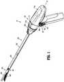
- a surgical instrumentin accordance with an embodiment of the present disclosure, is generally designated as 10, and is in the form of a powered hand held electromechanical instrument configured for performing various surgical functions, for example, stapling and cutting tissue.
- Surgical instrument 10includes a handle assembly 100 configured for selective connection with an adapter assembly 200, and, in turn, adapter assembly 200 is configured for selective connection with end effectors or single use loading units (“SULU's") 400.
- SULU'ssingle use loading units
- surgical instrument 10may include a variety of drive assemblies, for example, a drive assembly 300 shown in FIG. 5 , configured to transfer motion originating from handle assembly 100, through adapter assembly 200, and to SULU 400.
- handle assembly 100 of surgical instrument 10includes an outer shell housing 110 and a power pack 101 configured to be selectively received and substantially encased by outer shell housing 110.
- Outer shell housing 110includes a proximal portion or proximal half-section 110a and a distal portion or distal half-section 110b.
- Half-sections 110a, 110b of outer shell housing 110are pivotably connected to one another by a hinge 116 located along an upper edge of distal half-section 110b and proximal half-section 110a.
- proximal and distal half-sections 110a, 110bdefine a shell cavity 110c therein in which power-pack 101 is selectively situated.
- Proximal and distal half-sections 110a, 110bare divided along a plane that is perpendicular to a longitudinal axis "X" of adapter assembly 200.
- Each of proximal and distal half-sections 110a, 110bincludes a respective upper shell portion 112a, 112b, and a respective lower shell portion 114a, 114b.
- Lower shell portions 112a, 112bdefine a snap closure feature 118 for selectively securing lower shell portions 112a, 112b to one another and for maintaining outer shell housing 110 in a closed condition.
- Proximal half-section 110ais sized and shaped to house a majority of power pack 101 therein.
- Proximal half-section 110a of shell housing 110supports a right-side control button 36a and a left-side control button 36b.
- Right-side control button 36a and left-side control button 36bare capable of being actuated upon application of a corresponding force thereto or a depressive force thereto.
- Distal half-section 110b of outer shell housing 110covers a distal facing portion of power pack 101 when outer shell housing 110 is in the closed configuration, as shown in FIG. 4C .
- Distal half-section 110b of outer shell housing 110non-rotatably supports a drive member 312 of drive assembly 300 therein, as will be described in detail below with reference to FIG. 5 .
- Distal half-section 110bdefines a connecting portion 120 configured to accept a corresponding drive coupling assembly (not shown) of adapter assembly 200.
- distal half-section 110b of outer shell housing 110has a recess 122 that receives a portion (not shown) of the drive coupling assembly (not shown) of adapter assembly 200 when adapter assembly 200 is mated to handle assembly 100.
- Connecting portion 120 of distal half-section 110bdefines a pair of axially extending guide rails 120a, 120b projecting radially inward from inner side surfaces thereof. Guide rails 120a, 120b assist in rotationally orienting adapter assembly 200 relative to handle assembly 100 when adapter assembly 200 is mated to handle assembly 100.
- Connecting portion 120 of distal half-section 110bdefines three apertures 122a, 122b, 122c formed in a distally facing surface thereof and which are arranged in a common plane or line with one another.
- Connecting portion 120 of distal half-section 110balso defines an elongate slot 124 to contain a connector 166 also formed in the distally facing surface thereof.
- Connecting portion 120 of distal half-section 110bfurther defines a female connecting feature 126 formed in a surface thereof.
- Female connecting feature 126selectively engages with a male connecting feature (not shown) of adapter assembly 200.
- distal half-section 110bmay assume a variety of shapes that are each configured for non-rotatably housing a drive member of a drive assembly, for example, drive member 312 of drive assembly 300 shown in FIG. 5 .
- Distal half-section 110b of outer shell housing 110supports a distal facing toggle control button 130.
- Toggle control button 130is capable of being actuated in a left, right, up and down direction upon application of a corresponding force thereto or a depressive force thereto.
- Distal half-section 110b of outer shell housing 110supports a right-side pair of control buttons 32a, 32b; and a left-side pair of control button 34a, 34b.
- Right-side control buttons 32a, 32b and left-side control buttons 34a, 34bare capable of being actuated upon application of a corresponding force thereto or a depressive force thereto.
- Outer shell housing 110is fabricated from a polycarbonate or similar polymer, and is clear or transparent or may be overmolded. In some embodiments, outer shell housing 110 may be fabricated from any suitable material that can be sterilized, for example, by way of autoclaving.
- power-pack 101 of handle assembly 100is configured for receipt within outer shell housing 110 and for powering the functions of surgical instrument 10.
- Power-pack 101 of handle assembly 100includes an inner handle housing 150 having a lower housing portion 144 and an upper housing portion 148 extending from and/or supported on lower housing portion 144.
- Lower housing portion 144 and upper housing portion 148are separated into a proximal half-section 150a and a distal half-section 150b connectable to proximal half-section 150a by a plurality of fasteners.
- proximal and distal half-sections 150a, 150bdefine an inner handle housing 150 having an inner housing cavity (not shown) therein in which a power-pack core assembly (not shown) is situated.
- the power-pack core assemblyis configured to control the various operations of surgical instrument 10.
- Inner handle housing 150 of power pack 101provides a housing in which the power-pack core assembly is situated.
- the power-pack core assemblyincludes a battery circuit (not shown), a controller circuit board (not shown) and a rechargeable battery (not shown) configured to supply power to any of the electrical components of handle assembly 100.
- the controller circuit boardincludes a motor controller circuit board (not shown), a main controller circuit board (not shown), and a first ribbon cable (not shown) interconnecting the motor controller circuit board and the main controller circuit board.
- the power-pack core assemblyfurther includes a motor "M” electrically connected to the controller circuit board and the battery. It is contemplated that the power-pack core assembly may include more than one motor, for example, a second motor (not shown) and a third motor (not shown). Motor “M” is disposed between the motor controller circuit board and the main controller circuit board.
- the power-pack core assemblyhas a motor shaft or drive shaft 304 (also see FIG. 5 ) coupled to and rotatable by motor "M.”
- Motor “M”is controlled by a motor controller.
- the motor controlleris disposed on the motor controller circuit board and is, for example, A3930/31K motor drivers from Allegro Microsystems, Inc.
- the A3930/31K motor driversare designed to control a 3-phase brushless DC (BLDC) motor with N-channel external power MOSFETs, such as motor "M”.
- BLDC3-phase brushless DC
- Each of the motor controllersis coupled to a main controller disposed on the main controller circuit board.
- the main controlleris also coupled to memory, which is also disposed on the main controller circuit board.
- the main controlleris, for example, an ARM Cortex M4 processor from Freescale Semiconductor, Inc, which includes 1024 kilobytes of internal flash memory.
- the main controllercommunicates with the motor controllers through an FPGA, which provides control logic signals (e.g., coast, brake, etc.).
- the control logic of the motor controllerthen outputs corresponding energization signals to motor "M" using fixed-frequency pulse width modulation (PWM).
- PWMpulse width modulation
- Rotation of the motor shafts by the motors of power pack 101function to drive shafts and/or gear components of adapter assembly 200 in order to perform the various operations of surgical instrument 10.
- motor "M" of power-pack 101may be configured to drive shafts and/or gear components of outer shell housing 110, which drive corresponding driven shafts and/or gear components of adapter assembly 200 in order to selectively move tool assembly 404 ( FIG. 1 ) of SULU 400 relative to proximal body portion 402 of SULU 400, to rotate SULU 400 about a longitudinal axis "X”, to move cartridge assembly 408 relative to anvil assembly 406 of SULU 400, and/or to fire staples from within cartridge assembly 408 of SULU 400.
- adapter assembly 200 of surgical instrument 10is configured to transfer an axial translation of driven shaft 304 ( FIG. 3 ), which is disposed in outer shell housing 110, to SULU 400.
- Adapter assembly 200includes an outer knob housing 202 and an outer tube 206 extending from a distal end of knob housing 202.
- Knob housing 202 and outer tube 206are configured and dimensioned to house the components of adapter assembly 200.
- Outer tube 206is dimensioned for endoscopic insertion. In particular, outer tube 206 is passable through a typical trocar port, cannula or the like.
- Knob housing 202is dimensioned to not enter the trocar port, cannula or the like.
- Knob housing 202is configured and adapted to connect to connecting portion 120 of outer shell housing 110 of handle assembly 100.
- FIGS. 5-10various embodiments of a drive assembly of surgical instrument 10 are illustrated.
- Each drive assemblyextends longitudinally through power pack 101 of handle assembly 100, through outer shell housing 110 of handle assembly 110, and through adapter assembly 200.
- the drive assemblies of FIGS. 5-10are configured to transfer rotational motion originating from motor "M" of power pack 101 into axial translation of a drive member, for example, drive member 312 ( FIG. 5 ), disposed within outer shell housing 110. This motion, in turn, is transferred to a drive member 322 ( FIG. 5 ) disposed within adapter assembly 200, to ultimately effect surgical functions of surgical loading unit 400.
- rotational motion originating from motor "M" of power pack 101is converted into axial translation (i.e., movement along longitudinal axis "X") of the drive assembly at a location within outer shell housing 110.
- rotational motion of components of the drive assemblymay be converted into axial translation of components of the drive assembly at a location other than outer shell housing 110, for example, within power pack 101 or within adapter assembly 200.
- a drive assembly 300generally includes a first drive assembly 300a disposed within power pack 101, a second drive assembly 300b disposed within outer shell housing 110, and a third drive assembly 300c disposed within adapter assembly 200.
- First drive assembly 300a of power pack 101is operably coupled to second drive assembly 300b of outer shell housing 110 upon closing outer shell housing 110 with power pack 101 disposed therein
- second drive assembly 300b of outer shell housing 110is operably coupled to third drive assembly 300c of adapter assembly 200 upon attaching adapter assembly 200 to handle assembly 100.
- First drive assembly 300a of power pack 101includes a first drive shaft 302 coupled to and extending from motor "M" of power pack 101, and a second drive shaft or lead screw 304.
- First drive shaft 302has a gear, for example, a spur gear 306, non-rotatably coupled thereto.
- Second drive shaft 304has a proximal portion 304a and a distal portion 304b.
- Proximal portion 304a of second drive shaft 304has a gear 308 non-rotatably coupled thereto that is in operable engagement or meshing engagement with gear 306 of first drive shaft 302 such that rotation of first drive shaft 302, caused by actuation of motor "M,” drives a rotation of second drive shaft 304 within power pack 101.
- Distal portion 304b of second drive shaft 304has a threaded outer surface 310 configured for a detachable threading engagement with a threaded internal surface 314 of a drive member 312 of second drive assembly 300b of outer shell housing 110.
- first drive assembly 300a of power pack 101may have one drive shaft in the form of a lead screw 304 that extends directly and distally from motor "M.”
- second drive assembly 300bis disposed within distal-half section 110b of outer shell housing 110 of handle assembly 100 and extends along longitudinal axis "X" of surgical instrument 10.
- Second drive assembly 300bincludes a drive member, such as, for example, an elongated nut 312 that is non-rotatably supported in distal half-section 110b of outer shell housing 110.
- Elongated nut 312has a proximal portion 312a and a distal portion 312b.
- Proximal portion 312a of second drive assembly 300bhas a threaded internal surface 314 that defines a bore 316 longitudinally therethrough.
- distal portion 304b of second drive shaft 304 of first drive assembly 300aengages threaded internal surface 314 of drive member 312 of second drive assembly 300b.
- second drive shaft 304is rotated, which results in the threaded coupling between second drive shaft 304 of first drive assembly 300a and elongated nut 312 of second drive assembly 300b.
- Distal portion 312b of elongated nut 312 of second drive assembly 300bis configured to releasably connect to third drive assembly 300c of adapter assembly 200 upon connecting knob housing 202 of adapter assembly 200 to distal half-section 110b of outer shell housing 110.
- distal portion 312b of elongated nut 312may have a rounded joint or ball 318.
- Joint or ball 318 of elongated nut 312may project distally outside of distal half-section 110b of outer shell housing 110.
- Second drive assembly 300b of outer shell housing 110further includes a biasing member or coil spring 320 disposed about elongated nut 312.
- Coil spring 320resiliently biases elongated nut 312 in a proximal direction to assist in assembly of first drive assembly 300a with second drive assembly 300b.
- first and second drive assemblies 300a, 300bare operably connected to one another, a rotation of second drive shaft 304 of first drive assembly 300a drives an axial translation of elongated nut 312 of second drive assembly 300b.
- third drive assembly 300cis disposed within adapter assembly 200 and extends along longitudinal axis "X.”
- Third drive assembly 300cincludes a drive member 322 supported in knob housing 202 of adapter assembly 200 and may project proximally therefrom.
- Drive member 322 of third drive assembly 300chas a proximal end 322a and a distal end 322b.
- Proximal end 322a of drive member 322 of third drive assembly 300cmay be in the form of a collet that is configured to releasably receive joint 318 of elongated nut 312 of second drive assembly 300b.
- Collet 322ahas a pair of resilient arms 324 that snap fittingly engage cutouts 319 defined in joint 318 of elongated nut 312 of second drive assembly 300b.
- Distal end 322b of drive member 322 of third drive assembly 300cis configured to operatively couple to a component (not shown) of surgical loading unit 400 ( FIG. 1 ) and to operate a function or functions of surgical loading unit 400.
- Third drive assembly 300cfurther includes a biasing member or coil spring 326 disposed about drive member 322. Coil spring 326 resiliently biases drive member 322 in a proximal direction to assist in assembly of second drive assembly 300b with third drive assembly 300c.
- proximal and distal half-sections 110a, 110b of outer shell housing 110are pivoted away from one another to open outer shell housing 110 as described above with reference to FIGS. 4A-C .
- power pack 101which may be in a non-sterilized state, is inserted into outer shell housing 110, which is sterile.
- Proximal and distal half-sections 110a, 110b of outer shell housing 110are pivoted toward one another to close outer shell housing 110.
- first and second drive assemblies 300a, 300bengage one another.
- second drive shaft 304 of first drive assembly 300a of power pack 101engages elongated nut 312 of second drive assembly 300b of outer shell housing 110 to move elongated nut 312 in a distal direction against the proximally-oriented bias imparted on elongated nut 312 by coil spring 320.
- first and second drive assemblies 300a, 300bare not yet operatively coupled to one another.
- motor "M" of power pack 101is actuated to rotate second drive shaft 304 of first drive assembly 300a.
- Rotation of second drive shaft 304 of first drive assembly 300acauses threaded outer surface 310 of second drive shaft 304 to catch threaded internal surface 314 of elongated nut 312 to ultimately cause second drive shaft 304 to be disposed within bore 316 of elongated nut 312.
- third drive assembly 300c of adapter assembly 200may then be operatively coupled to second drive assembly 300b of outer shell housing 110. It is contemplated that adapter assembly 200 may be operatively coupled to outer shell housing 110 prior to operatively coupling power pack 101 to outer shell housing 110.
- the drive coupling assembly (not shown) of knob housing 202 of adapter assembly 200is received within connecting portion 120 ( FIG. 3 ) of distal half-section 110b of outer shell housing 110.
- collet 322a of drive member 322 of adapter assembly 200receives joint 318 of elongated nut 312 of outer shell housing 110 to operatively couple drive member 322 of adapter assembly 200 to elongated nut 312 of outer shell housing 110.
- a motorfor example, motor "M” of power pack 101 is actuated, which rotates first drive shaft 302 of power pack 100, and in turn, rotates second drive shaft 304 of power pack 101, via the interactions between gears 306, 308 of first and second drive shafts 302, 304, respectively.
- the rotation of second drive shaft 304drives a proximal or distal longitudinal movement of elongated nut 312 of outer shell housing 110 due to second drive shaft 304 of power pack 101 being threadingly engaged to elongated nut 312 of outer shell housing 110.
- Proximal or distal longitudinal movement of elongated nut 312results in a corresponding motion of drive member 322 of adapter assembly 200 as a result of elongated nut 312 of outer shell housing 110 being attached to drive member 322 of adapter assembly 200. Since distal end 322b of drive member 322 of adapter assembly 200 is operatively connected to a working component(s) (not shown) of surgical loading unit 400, the axial movement of drive member 322 of adapter assembly 200 effects various functions of surgical loading unit 400, for example, opening or closing of its jaw members 406, 408, a stapling function, and/or a cutting function.
- knob housing 202 of adapter assembly 200may be manually detached from handle assembly 100, thereby causing joint 318 of elongated nut 312 of outer shell housing 110 to disengage collet 322a of drive member 322 of adapter assembly 200.
- first drive assembly 300a of power pack 101Prior to removing power pack 101 from outer shell housing 110, first drive assembly 300a of power pack 101 is disengaged from second drive assembly 300b.
- motor "M" of power pack 101is actuated to rotate first drive shaft 302, and in turn, second drive shaft 304.
- Second drive shaft 304 of first drive assembly 300acauses second drive shaft 304 of first drive assembly 300a to back out of bore 316 of elongated nut 312 by pushing elongated nut 312 in a distal direction.
- Second drive shaft 304is rotated until its threaded outer surface 310 is out of threading engagement with threaded internal surface 314 of elongated nut 312.
- snap closure feature 118 of outer shell housing 110is unsnapped and outer shell housing 110 is opened. With outer shell housing 110 in the opened configuration, as shown in FIG. 4B , power pack 101 can be removed from outer shell housing 110.
- Outer shell housing 110may then be re-sterilized or re-cleaned for re-use.
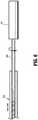
- Drive assembly 500generally includes a drive shaft or lead screw 502 disposed within power pack 101, a drive member 512 disposed within outer shell housing 110, and a drive member 522 disposed within adapter assembly 200.
- Lead screw 502 of power pack 101is operably coupled to drive member 512 of outer shell housing 110 upon closing outer shell housing 110 with power pack 101 disposed therein, and drive member 512 of outer shell housing 110 is operably coupled to drive member 522 of adapter assembly 200 upon attaching adapter assembly 200 to handle assembly 100.
- Lead screw 502 of drive assembly 500is disposed within power pack 101 and is coupled to and extends from motor "M" of power pack 101.
- Drive member 512 of outer shell housing 110is in the form of a coupling member that is configured to convert a rotation of lead screw 502 of power pack 101 into a translation of drive assembly 500 within outer shell housing 110.
- Coupling member 512is restrained within power pack 101 so as to prevent coupling member 512 from rotating therein.
- Coupling member 512 of drive assembly 500is disposed within outer shell housing 110 and has a nut 512a, and a post 512b extending from nut 512a.
- Nut 512a of coupling member 512is configured to be threadingly engaged to lead screw 502 of power pack 101 such that rotation of lead screw 502 of power pack 101, caused by actuation of motor "M" of power pack 101, causes coupling member 512 of outer shell housing 110 to translate along lead screw 502.
- Post 512b of coupling member 512has a first end 512c and a second end 512d and extends along an axis that is perpendicular to longitudinal axis "X" of surgical instrument 10.
- First end 512c of post 512bis monolithically formed with nut 512a, but it is contemplated that first end 512c of post 512b may be attached to nut 512a via any suitable engagement.
- Second end 512b of post 512bhas a mating part 514 configured for detachable mating with a corresponding mating part 524 of drive member 522 of adapter assembly 200.
- Mating part 514is a step or squared cutout defined in second end 512d of post 512b.
- mating part 514 of coupling member 512may be any suitable male or female mating part.
- Drive member 522 of drive assembly 500is disposed within adapter assembly 200 and extends along longitudinal axis "X" of surgical instrument 10.
- Drive member 522is an elongated shaft having a proximal end 522a and a distal end 522b.
- Proximal end 522a of drive member 522has a mating part 524, similar to mating part 514 of coupling member 512 outer shell housing 110.
- Mating part 524 of drive member 522 of adapter assembly 200is configured for detachable mating with mating part 514 of coupling member 512 of outer shell housing 110.
- Distal end 522b of drive member 522 of adapter assembly 200is configured to operatively couple to a component (not shown) of surgical loading unit 400 to operate a function or functions of surgical loading unit 400.
- proximal and distal half-sections 110a, 110b of outer shell housing 110are pivoted away from one another to open outer shell housing 110.
- power pack 101which may be in a non-sterilized state, is inserted into outer shell housing 110, which is sterile.
- Proximal and distal half-sections 110a, 110b of outer shell housing 110are pivoted toward one another to close outer shell housing 110.
- drive assembly 500is assembled.
- lead screw 502 of power pack 101engages nut 512a of coupling member 512 of outer shell housing 110 to move coupling member 512 in a distal direction against a proximally oriented bias imparted on coupling member 512 by a coil spring (not shown).
- lead screw 502 of power pack 101 and coupling member 512 of outer shell housing 110are not yet operatively coupled to one another.
- motor "M" of power pack 101is actuated to rotate lead screw 502 of power pack 101.
- Rotation of lead screw 502 of power pack 101causes a threaded outer surface of lead screw 502 to catch a threaded internal surface (not shown) of nut 512a of coupling member 512 to ultimately cause lead screw 502 to be disposed within nut 512a of coupling member 512.
- adapter assembly 200may then be operatively coupled to outer shell housing 110. It is contemplated that adapter assembly 200 may be operatively coupled to outer shell housing 110 prior to operatively coupling power pack 101 to outer shell housing 110.
- the drive coupling assembly (not shown) of knob housing 202 of adapter assembly 200is received within connecting portion 120 ( FIG. 3 ) of distal half-section 110b of outer shell housing 110.
- mating part 524 of drive member 522 of adapter assembly 200interlocks with mating part 514 of coupling member 512 of outer shell housing 110 to operatively couple drive member 522 of adapter assembly 200 to coupling member 512 of outer shell housing 110.
- drive assembly 500 of surgical instrument 10After drive assembly 500 of surgical instrument 10 is assembled, operation of surgical instrument 10 may be performed.
- motor "M" of power pack 101is actuated, which rotates lead screw 502 of power pack 101.
- Rotation of lead screw 502 of power pack 101drives a proximal or distal longitudinal movement of coupling member 512 of outer shell housing 110 therealong.
- Proximal or distal longitudinal movement of coupling member 512 of outer shell housing 110results in a corresponding motion of drive member 522 of adapter assembly 200 as a result of coupling member 512 of outer shell housing 110 being attached to drive member 522 of adapter assembly 200.
- distal end 522b of drive member 522 of adapter assembly 200is operatively connected to working component(s) (not shown) of surgical loading unit 400, the axial movement of drive member 522 of adapter assembly 200 effects various functions of surgical loading unit 400, for example, opening or closing of its jaw members 406, 408, a stapling function, and/or a cutting function.
- knob housing 202 of adapter assembly 200may be manually detached from handle assembly 100, thereby causing mating part 524 of drive member 522 of adapter assembly 200 to disengage mating part 514 of coupling member 512 of outer shell housing 110.
- lead screw 502 of power pack 101Prior to removing power pack 101 from outer shell housing 110, lead screw 502 of power pack 101 is disengaged from coupling member 512 of outer shell housing 110.
- motor "M" of power pack 101is actuated to rotate lead screw 502. Rotation of lead screw 502 of power pack 101 causes lead screw 502 of power pack 101 to back out of nut 512a of coupling member 512 while pushing coupling member 512 in a distal direction.
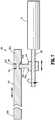
- Drive assembly 600generally includes a drive shaft assembly 602 disposed within power pack 101, a drive member 612 disposed within outer shell housing 110, and a drive member 622 disposed within adapter assembly 200.
- Drive shaft assembly 602 of power pack 101is operably coupled to drive member 612 of outer shell housing 110 upon closing outer shell housing 110 with power pack 101 disposed therein, and drive member 612 of outer shell housing is operably coupled to the drive member (not shown) of adapter assembly 200 upon attaching adapter assembly 200 to handle assembly 100.
- Drive shaft assembly 602 of drive assembly 600is disposed within power pack 101 and includes a drive shaft 604 coupled to and extending from motor "M" of power pack 101, a first gear 606, and a second gear or coupling gear 608.
- First gear 606is non-rotatably coupled to drive shaft 604 and defines a rotation axis that is parallel to longitudinal axis "X" of surgical instrument 10.
- First gear 606is in the form of a bevel gear, but in some embodiments, first gear 606 may be any suitable gear.
- Second gear or coupling gear 608is in operable engagement or meshing engagement with first gear 606.
- Coupling gear 608defines a rotation axis that is perpendicular to the rotation axis of first gear 606.
- Coupling gear 608is a compound bevel-spur gear. Specifically, coupling gear 608 includes a bevel gear 608a and a spur gear 608b extending from bevel gear 608a. Bevel gear 608a of coupling gear 608 is in operable engagement with first gear 606 of drive shaft 604. Spur gear 608b of coupling gear 608 is configured to be in operable engagement with drive member 612 of outer shell housing 110 upon closing outer shell housing 110 around power pack 101.
- Drive member 612 of outer shell housing 110is in the form of a longitudinal rack that is configured to convert a rotation of coupling gear 608 of power pack 101 into a translation of drive assembly 600 within outer shell housing 110.
- Rack 612 of outer shell housing 110has a proximal portion 612a and a distal portion (not explicitly shown) and extends along longitudinal axis "X" of surgical instrument 10.
- Proximal portion 612ahas a plurality of teeth 614 configured to operably engage or meshingly engage spur gear 608b of second gear 608 such that rotation of coupling gear 608 of power pack 101, caused by actuation of motor "M" of power pack 101, causes rack 612 of outer shell housing 110 to axially translate.
- the distal end of rack 612 of outer shell housing 110is configured for detachable mating engagement with a mating part of the drive member (not shown) of adapter assembly 200. It is contemplated that the distal end of rack 612 and a proximal end of the drive member of adapter assembly 200 releasably engage one another in a similar manner as that described with reference to second and third drive assemblies 300b, 300c of FIG. 5 .
- the distal end of the drive member of adapter assembly 200is configured to operatively couple to component(s)(not shown) of surgical loading unit 400 to operate a function or functions of surgical loading unit 400.
- proximal and distal half-sections 110a, 110b of outer shell housing 110are pivoted away from one another to open outer shell housing 110.
- power pack 101which may be in a non-sterilized state, is inserted into a sterilized outer shell housing 110.
- Proximal and distal half-sections 110a, 110b of outer shell housing 110are pivoted toward one another to close outer shell housing 110.
- drive assembly 600is assembled.
- Adapter assembly 200may then be operatively coupled to outer shell housing 110 in a similar manner described above with reference to FIGS. 5-7 . It is contemplated that adapter assembly 200 may be operatively coupled to outer shell housing 110 prior to operatively coupling power pack 101 to outer shell housing 110.
- drive assembly 600 of surgical instrument 10After drive assembly 600 of surgical instrument 10 is assembled, operation of surgical instrument 10 may be performed.
- motor "M" of power pack 101is actuated, which rotates first gear 606 of power pack 101.
- Rotation of first gear 606drives a rotation of coupling gear 608, which in turn drives a proximal or distal longitudinal movement of rack 612 of outer shell housing 110.
- Proximal or distal longitudinal movement of rack 612 of outer shell housing 110results in a corresponding motion of the drive member of adapter assembly 200 as a result of rack 612 of outer shell housing 110 being attached to the drive member of adapter assembly 200.
- the axial movement of the drive member of adapter assembly 200effects various functions of surgical loading unit 400, for example, opening or closing of its jaw members 406, 408, a stapling function, and/or a cutting function.
- knob housing 202 of adapter assembly 200may be manually detached from handle assembly 100, in a similar manner described above with respect to FIGS. 5-7 .
- Snap closure feature 118 of outer shell housing 110is unsnapped and outer shell housing 110 is opened, as shown in FIG. 4B . With outer shell housing 110 in the open configuration, power pack 101 can be removed from outer shell housing 110.
- Drive assembly 700generally includes a drive shaft assembly 702 disposed within power pack 101, a drive member 712 disposed within outer shell housing 110, and a drive member (not shown) disposed within adapter assembly 200.
- Drive shaft assembly 702 of power pack 101is operably coupled to drive member 712 of outer shell housing 110 upon closing outer shell housing 110 with power pack 101 disposed therein, and drive member 712 of outer shell housing 110 is operably coupled to the drive member of adapter assembly 200 upon attaching adapter assembly 200 to handle assembly 100.
- Drive shaft assembly 702 of drive assembly 700is disposed within power pack 101 and includes a drive shaft 704 coupled to and extending from motor "M" of power pack 101, a first gear (not explicitly shown), and a second gear or coupling gear 708.
- Drive shaft assembly 702 of power pack 101is similar to drive shaft assembly 602 described above with reference to FIGS. 8A and 8B , and will therefore not be described in detail herein.
- Drive member 712 of outer shell housingis in the form of a plurality of racks that are configured to convert a rotation of coupling gear 708 of power pack 101 into a translation of drive assembly 700 within outer shell housing 110.
- Racks 712 of outer shell housing 110are coupled to one another to form a train of racks.
- Each rack 712may be coupled to an adjacent rack 712 by a ball and socket connection 714, a relatively rigid tether, or any other suitable connection that permits racks 712 to pivot relative to one another, but resists pivoting of racks 712 relative to one another unless a threshold force is applied. As such, racks 712 will maintain a generally linear configuration if no force is acting on racks 712.
- Racks 712each have a concave surface having teeth 716 projecting therefrom.
- the toothed surface 716 of each rack 712is concave to cup coupling gear 708 of power pack 101 upon outer shell housing 110 closing around power pack 101.
- Racks 712are disposed between two plates or tracks 718 that are fixed within distal half-section 110b of outer shell housing 110. Plates 718 prevent racks 712 from buckling, thereby guiding racks 712 along longitudinal axis "X.”
- Drive assembly 700further includes a firing rod or shaft 720 extending distally from a distal-most rack 712b.
- a distal end of firing rod 720 of outer shell housing 110is configured for detachable mating engagement with a mating part (not shown) of the drive member (not shown) of adapter assembly 200. It is contemplated that the distal end of firing rod 720 of outer shell housing 110 and a proximal end of the drive member of adapter assembly 200 releasably engage one another in a similar manner as that described with reference to second and third drive assemblies 300b, 300c of FIG. 5 .
- the distal end of the drive member of adapter assembly 200is configured to operatively couple to a component(s)(not shown) of surgical loading unit 400 to operate a function or functions of surgical loading unit 400.
- proximal and distal half-sections 110a, 110b of outer shell housing 110are pivoted away from one another to open outer shell housing 110.
- power pack 101which may be in a non-sterilized state, is inserted into a sterilized outer shell housing 110.
- Proximal and distal half-sections 110a, 110b of outer shell housing 110are pivoted toward one another to close outer shell housing 110.
- drive assembly 700is assembled.
- Adapter assembly 200may then be operatively coupled to outer shell housing 110 in a similar manner described above with reference to FIGS. 5-7 . It is contemplated that adapter assembly 200 may be operatively coupled to outer shell housing 110 prior to operatively coupling power pack 101 to outer shell housing 110.
- drive assembly 700 of surgical instrument 10After drive assembly 700 of surgical instrument 10 is assembled, operation of surgical instrument 10 may be performed.
- motor "M" of power pack 101is actuated, which rotates first gear (not explicitly shown) of power pack 101.
- Rotation of the first geardrives a rotation of second gear 708, which in turn drives a proximal or distal longitudinal movement of racks 712 of outer shell housing 110 through tracks 718 of outer shell housing 110.
- Proximal or distal longitudinal movement of racks 712 of outer shell housing 110results in a corresponding motion of firing rod 720 of outer shell housing 110 and the drive member (not shown) of adapter assembly 200 as a result of firing rod 720 of outer shell housing 110 being attached to the drive member of adapter assembly 200.
- the axial movement of the drive member of adapter assembly 200effects various functions of surgical loading unit 400, for example, opening or closing of its jaw members 406, 408, a stapling function, and/or a cutting function.
- knob housing 202 of adapter assembly 200may be manually detached from handle assembly 100, in a similar manner described above with respect to FIGS. 5-7 .
- Snap closure feature 118 of outer shell housing 110is unsnapped and motor "M" of power pack 101 is actuated until each of racks 712 are out of engagement with second gear 708 of power pack 101 and proximal-most rack 712a is disposed distally of second gear 708 of power pack 101.
- Outer shell housing 110may then be opened. With outer shell housing 110 in the open configuration, as shown in FIG. 4B , power pack 101 can be removed from outer shell housing 110.
- Drive assembly 800generally includes a drive shaft assembly 802 disposed within power pack 101, a drive member 812 disposed within outer shell housing 110, and a drive member (not shown) disposed within adapter assembly 200.
- Drive shaft assembly 802 of power pack 101is operably coupled to drive member 812 of outer shell housing 110 upon closing outer shell housing 110 with power pack 101 disposed therein, and drive member 812 of outer shell housing 110 is operably coupled to the drive member of adapter assembly 200 upon attaching adapter assembly 200 to handle assembly 100, as will be described in detail below.
- Drive shaft assembly 802 of drive assembly 800is disposed within power pack 101 and includes a drive shaft (not explicitly shown) coupled to and extending from motor "M" of power pack 101, a first gear 804, and a second gear or coupling gear 808.
- Drive shaft assembly 802 of power pack 101is similar to drive shaft assembly 602 described above with reference to FIGS. 8A and 8B , and will therefore not be described in further detail herein.
- Drive member 812 of outer shell housing 110is in the form of an elongated ribbon that is configured to convert a rotation of second gear 808 of power pack 101 into a translation of drive assembly 800 within outer shell housing 110.
- Ribbon 812 of outer shell housing 110resists bending or folding unless a threshold force is applied. As such, ribbon 812 will maintain a generally linear configuration if no force is acting thereon.
- Ribbon 812defines a plurality of slits 816 therein configured for receipt of teeth of spur gear 808b of second gear 808 of power pack 101.
- Ribbon 812is disposed between two plates or tracks 818 that are fixed within distal half-section 110b of outer shell housing 110. Tracks 818 prevent ribbon 812 from buckling, thereby guiding ribbon 812 along longitudinal axis "X.”
- a firing rod or shaft 820extends distally from a distal end of ribbon 812.
- a distal end of firing rod 820 of outer shell housing 110is configured for detachable mating engagement with a mating part (not shown) of the drive member (not shown) of adapter assembly 200. It is contemplated that the distal end of firing rod 820 and a proximal end of the drive member of adapter assembly 200 releasably engage one another in a similar manner as that described above with reference to second and third drive assemblies 300b, 300c of FIG. 5 .
- the distal end of the drive member of adapter assembly 200is configured to operatively couple to a component(s)(not shown) of surgical loading unit 400 to operate a function or functions of surgical loading unit 400.
- proximal and distal half-sections 110a, 110b of outer shell housing 110are pivoted away from one another to open outer shell housing 110, as shown in FIG. 4B .
- power pack 101which may be in a non-sterilized state, is inserted into a sterilized outer shell housing 110.
- Proximal and distal half-sections 110a, 110b of outer shell housing 110are pivoted toward one another to close outer shell housing 110.
- drive assembly 800is assembled.
- Adapter assembly 200may then be operatively coupled to outer shell housing 110 in a similar manner described above with reference to FIGS. 5-7 . It is contemplated that adapter assembly 200 may be operatively coupled to outer shell housing 110 prior to operatively coupling power pack 101 to outer shell housing 110.
- drive assembly 800 of surgical instrument 10After drive assembly 800 of surgical instrument 10 is assembled, operation of surgical instrument 10 may be performed.
- motor "M" of power pack 101is actuated, which rotates first gear 804 of power pack 101.
- Rotation of first gear 804drives a rotation of second gear 808, which in turn causes ribbon 812 to wrap thereabout and drives a proximal or distal longitudinal movement of ribbon 812 of outer shell housing 110 through tracks 818 of outer shell housing 110.
- Proximal or distal longitudinal movement of ribbon 812 of outer shell housing 110results in a corresponding motion of firing rod 820 of outer shell housing 110 and the drive member of adapter assembly 200 as a result of firing rod 820 of outer shell housing 110 being attached to the drive member of adapter assembly 200.
- the axial movement of the drive member of adapter assembly 200effects various functions of surgical loading unit 400, for example, opening or closing of its jaw members 406, 408, a stapling function, and/or a cutting function.
- knob housing 202 of adapter assembly 200may be manually detached from handle assembly 100, in a similar manner described above with respect to FIGS. 5-7 .
- Snap closure feature 118 of outer shell housing 110is unsnapped and motor "M" of power pack 101 is actuated until ribbon 812 unravels from around second gear 808 of power pack 101 and teeth of second gear 808 of power pack 101 are removed from slits 816 of ribbon 812.
- Outer shell housing 110may then be opened. With outer shell housing 110 in the open configuration, power pack 101 can be removed from outer shell housing 110.
Landscapes
- Health & Medical Sciences (AREA)
- Life Sciences & Earth Sciences (AREA)
- Surgery (AREA)
- Heart & Thoracic Surgery (AREA)
- Engineering & Computer Science (AREA)
- Biomedical Technology (AREA)
- Nuclear Medicine, Radiotherapy & Molecular Imaging (AREA)
- Medical Informatics (AREA)
- Molecular Biology (AREA)
- Animal Behavior & Ethology (AREA)
- General Health & Medical Sciences (AREA)
- Public Health (AREA)
- Veterinary Medicine (AREA)
- Surgical Instruments (AREA)
Description
- The present disclosure relates to surgical instruments. More specifically, the present disclosure relates to handheld electromechanical surgical instruments for performing surgical procedures.
- One type of surgical instrument is a linear clamping, cutting and stapling instrument. Such an instrument may be employed in a surgical procedure to resect a cancerous or anomalous tissue from a gastro-intestinal tract. Conventional linear clamping, cutting and stapling instruments include a pistol grip-styled structure having an elongated shaft and distal portion. The distal portion includes a pair of scissors-styled gripping elements, which clamp the open ends of the colon closed. In this instrument, one of the two scissors-styled gripping elements, such as the anvil portion, moves or pivots relative to the overall structure, whereas the other gripping element remains fixed relative to the overall structure. The actuation of this scissoring mechanism (the pivoting of the anvil portion) is controlled by a grip trigger maintained in the handle.
- In addition to the gripping elements, the distal portion also includes a stapling mechanism. The fixed gripping element of the scissoring mechanism includes a staple cartridge receiving region and a mechanism for driving the staples up through the clamped end of the tissue against the anvil portion, thereby sealing the previously opened end. The gripping elements may be integrally formed with the shaft or may be detachable such that various scissoring and stapling elements may be interchangeable.
- A number of surgical instrument manufacturers have developed product lines with proprietary powered drive systems for operating and/or manipulating the surgical instrument. In many instances the surgical instruments include a powered handle assembly, which is reusable, and a disposable end effector or the like that is selectively connected to the powered handle assembly prior to use and then disconnected from the end effector following use in order to be disposed of or in some instances sterilized for re-use.
- Many of the existing end effectors for use with many of the existing powered handle assemblies are driven by a linear force. For example, end effectors for performing endo-gastrointestinal anastomosis procedures, end-to-end anastomosis procedures and transverse anastomosis procedures, each typically require a linear driving force in order to be operated. As such, these end effectors cannot be directly attached to handle assemblies that use a rotary motion to deliver power or the like.
- In order to make the linear driven end effectors compatible with powered surgical handle assemblies that use a rotary motion to deliver power, a need exists for a way to convert rotation originating in the handle assembly into linear motion for driving the operations of the attached end effector. Typically, adapters that intercouple an end effector with a powered handle assembly are used to provide this conversion of rotation to translation.
EP 2668910 discloses a surgical instrument that includes a power pack, an outer shell housing configured to selectively encase the power pack, and an adapter assembly configured to selectively couple the outer shell housing to a loading unit. The outer shell housing includes a motor and a drive shaft coupled to and rotatable by the motor. The outer shell housing includes a drive member supported in a distal portion thereof. The drive member is configured to selectively couple to the drive shaft. The adapter assembly has a drive member supported in its proximal end. The drive member of the adapter assembly is configured to selectively couple to the drive member of the outer shell housing such that rotation of the drive shaft actuates movement of the drive member of the adapter assembly via the drive member of the outer shell housing. - Accordingly, a need exists for alternative ways of converting the rotational motion originating in the handle assemblies into linear motion.
- The invention is disclosed in the appended set of claims.
- In one aspect of the present disclosure, a surgical instrument is provided, which includes a power pack, an outer shell housing, and an adapter assembly. The power pack includes a motor and a drive shaft coupled to and rotatable by the motor. The outer shell housing is configured to selectively encase the power pack therein and includes a first drive member supported in a distal portion of the outer shell housing. The first drive member is configured to selectively couple to the drive shaft. The adapter assembly has a proximal end configured to selectively couple to the outer shell housing, and a distal end configured to couple to a loading unit. The adapter assembly has a second drive member supported in the proximal end. The second drive member is configured to selectively couple to the first drive member such that rotation of the drive shaft actuates the second drive member through the first drive member.
- In some embodiments, the outer shell housing may be transitionable between an open configuration and a closed configuration. In the open configuration, the power pack may be insertable and/or removable from the outer shell housing. In the closed configuration, the power pack may be enclosed within the outer shell housing. The outer shall housing may have a proximal portion pivotably coupled to the distal portion of the outer shell housing such that in the open configuration, a portion of the proximal portion of the outer shell housing is spaced from a corresponding portion of the distal portion of the outer shell housing.
- In some embodiments, in the closed configuration, the portion of the proximal portion of the outer shell housing may be connected to the corresponding portion of the distal portion of the outer shell housing. In the closed configuration, the drive shaft may be operably connected to the first drive member. In the open configuration, the drive shaft may be disconnected from the first drive member.
- In some embodiments, rotation of the drive shaft may axially move the first drive member when the first drive member is operably connected to the drive shaft of the power pack.
- In some embodiments, the drive shaft may be a lead screw. The first drive member of the outer shell housing may be an elongated nut threadingly engaged to the lead screw such that rotation of the lead screw axially moves the elongated nut relative to the lead screw. The first drive member may include a nut threadingly engaged to the lead screw, and a post extending from the nut. The post may have a mating part configured to detachably mate with a corresponding mating part of the second drive member such that rotation of the lead screw translates the first drive member therealong to translate the second drive member.
- In some embodiments, the surgical instrument may further include a coupling gear configured to interconnect the drive shaft and the first drive member. The drive shaft may include a first bevel gear configured to operably engage the coupling gear. The coupling gear may include a second bevel gear in operable engagement with the first bevel gear, and a spur gear extending from the second bevel gear and in operable engagement with the first drive member.
- In some embodiments, the first drive member may be a longitudinal rack having teeth in operable engagement with the spur gear of the coupling gear such that rotation of the first bevel gear axially moves the longitudinal rack. The first drive member may include two racks pivotably joined to one another. Each rack may have teeth in operable engagement with the spur gear of the coupling gear such that rotation of the first bevel gear axially moves at least one of the two racks.
- In some embodiments, the first drive member may be an elongated ribbon including a proximal end and a distal end. The proximal end of the ribbon is disposed about the spur gear and defines a plurality of slits for receipt of teeth of the spur gear. The distal end of the ribbon is disposed within a linear track defined in the outer shell housing such that rotation of the coupling gear rotates the proximal end of the ribbon to axially move the distal end of the ribbon through the linear track.
- In some embodiments, the second drive member may have a proximal end configured for snap fit engagement with a distal end of the drive member of the outer shell housing.
- In another aspect of the present disclosure, a handle assembly is provided, which includes a power pack and an outer shell housing. The power pack includes a motor and a drive shaft coupled to and rotatable by the motor. The outer shell housing is configured to selectively encase the power pack therein and includes a drive member supported in a distal portion of the outer shell housing. The drive member is configured to selectively couple to the drive shaft of the power pack and a drive member of an adapter assembly. The drive shaft is configured to actuate movement of the drive member of the outer shell housing upon rotation of the drive shaft.
- In yet another aspect of the present disclosure, anouter shell housing for selectively encasing a power pack therein is provided. The outer shell housing includes a proximal portion defining a cavity therein, and a distal portion defining a cavity therein. The distal portion is pivotably coupled to the proximal portion between an open configuration, in which a portion of the proximal portion is spaced from a corresponding portion of the distal portion, and a closed configuration, in which the portion of the proximal portion is connected to the corresponding portion of the distal portion. The outer shell housing further includes a drive member supported in the distal portion. The drive member is configured to selectively interconnect a drive shaft of a power pack and a drive member of an adapter assembly.
- In some embodiments, in the closed configuration, the proximal portion and the distal portion may cooperatively define an internal cavity configured for encasing a power pack. In the open configuration, a power pack may be insertable and/or removable from the outer shell housing.
- The present disclosure relates to electromechanical surgical instruments for performing surgical procedures.
- Embodiments of the present disclosure are described herein with reference to the accompanying drawings, wherein:
FIG. 1 is a perspective view of a handheld surgical instrument including a handle assembly, an adapter assembly, and a surgical loading unit, in accordance with an embodiment of the present disclosure;FIG. 2 is a perspective view of the handle assembly ofFIG. 1 ;FIG. 3 is a front perspective view, with parts separated, of the handle assembly ofFIG. 2 including an outer shell housing and a power pack;FIG. 4A is a side view of the surgical instrument ofFIG. 1 illustrating the outer shell housing ofFIG. 3 in an open configurationFIG. 4B is a side view of the surgical instrument ofFIG. 1 illustrating the outer shell housing ofFIG. 3 in the open configuration with the power pack disposed therein;FIG. 4C is a side view of the surgical instrument ofFIG. 1 illustrating the outer shell housing ofFIG. 3 in a closed configuration;FIG. 5 is a side, cross-sectional view of one embodiment of a drive assembly that extends longitudinally through the power pack ofFIG. 3 , the outer shell housing ofFIG. 3 , and the adapter assembly ofFIG. 1 ;FIG. 6 is a side, cross-sectional view of another embodiment of a drive assembly that extends longitudinally through the power pack ofFIG. 3 , the outer shell housing ofFIG. 3 , and the adapter assembly ofFIG. 1 ;FIG. 7 is a side, cross-sectional view of yet another embodiment of a drive assembly that extends longitudinally through the power pack ofFIG. 3 , the outer shell housing ofFIG. 3 , and the adapter assembly ofFIG. 1 ;FIG. 8A is a side view of yet another embodiment of a drive assembly that extends longitudinally through the power pack ofFIG. 3 , the outer shell housing ofFIG. 3 , and the adapter assembly ofFIG. 1 ;FIG. 8B is front view of the drive assembly ofFIG. 8A ;FIG. 9 is a perspective view of yet another embodiment of a drive assembly that extends longitudinally through the power pack ofFIG. 3 , the outer shell housing ofFIG. 3 , and the adapter assembly ofFIG. 1 ; andFIG. 10 is a perspective view of yet another embodiment of a drive assembly that extends longitudinally through the power pack ofFIG. 3 , the outer shell housing ofFIG. 3 , and the adapter assembly ofFIG. 1 .- Embodiments of the presently disclosed surgical instruments including handle assemblies, adapter assemblies, and drive assemblies, are described in detail with reference to the drawings, in which like reference numerals designate identical or corresponding elements in each of the several views. As used herein the term "distal" refers to that portion of the surgical instrument, or component thereof, farther from the user, while the term "proximal" refers to that portion of the surgical instrument, or component thereof, closer to the user.
- With reference to
FIG. 1 , a surgical instrument, in accordance with an embodiment of the present disclosure, is generally designated as 10, and is in the form of a powered hand held electromechanical instrument configured for performing various surgical functions, for example, stapling and cutting tissue.Surgical instrument 10 includes ahandle assembly 100 configured for selective connection with anadapter assembly 200, and, in turn,adapter assembly 200 is configured for selective connection with end effectors or single use loading units ("SULU's") 400. As described in detail below,surgical instrument 10 may include a variety of drive assemblies, for example, a drive assembly 300 shown inFIG. 5 , configured to transfer motion originating fromhandle assembly 100, throughadapter assembly 200, and toSULU 400. - As illustrated in
FIGS. 1-4C , handleassembly 100 ofsurgical instrument 10 includes anouter shell housing 110 and apower pack 101 configured to be selectively received and substantially encased byouter shell housing 110.Outer shell housing 110 includes a proximal portion or proximal half-section 110a and a distal portion or distal half-section 110b. Half-sections outer shell housing 110 are pivotably connected to one another by ahinge 116 located along an upper edge of distal half-section 110b and proximal half-section 110a. When joined, proximal and distal half-sections shell cavity 110c therein in which power-pack 101 is selectively situated. Proximal and distal half-sections adapter assembly 200. Each of proximal and distal half-sections upper shell portion lower shell portion Lower shell portions snap closure feature 118 for selectively securinglower shell portions outer shell housing 110 in a closed condition. - Proximal half-
section 110a is sized and shaped to house a majority ofpower pack 101 therein. Proximal half-section 110a ofshell housing 110 supports a right-side control button 36a and a left-side control button 36b. Right-side control button 36a and left-side control button 36b are capable of being actuated upon application of a corresponding force thereto or a depressive force thereto. - Distal half-
section 110b ofouter shell housing 110 covers a distal facing portion ofpower pack 101 whenouter shell housing 110 is in the closed configuration, as shown inFIG. 4C . Distal half-section 110b ofouter shell housing 110 non-rotatably supports adrive member 312 of drive assembly 300 therein, as will be described in detail below with reference toFIG. 5 . Distal half-section 110b defines a connectingportion 120 configured to accept a corresponding drive coupling assembly (not shown) ofadapter assembly 200. Specifically, distal half-section 110b ofouter shell housing 110 has arecess 122 that receives a portion (not shown) of the drive coupling assembly (not shown) ofadapter assembly 200 whenadapter assembly 200 is mated to handleassembly 100. Connectingportion 120 of distal half-section 110b defines a pair of axially extendingguide rails Guide rails adapter assembly 200 relative to handleassembly 100 whenadapter assembly 200 is mated to handleassembly 100. Connectingportion 120 of distal half-section 110b defines threeapertures portion 120 of distal half-section 110b also defines anelongate slot 124 to contain aconnector 166 also formed in the distally facing surface thereof. Connectingportion 120 of distal half-section 110b further defines a female connectingfeature 126 formed in a surface thereof. Female connectingfeature 126 selectively engages with a male connecting feature (not shown) ofadapter assembly 200. It is contemplated that distal half-section 110b may assume a variety of shapes that are each configured for non-rotatably housing a drive member of a drive assembly, for example,drive member 312 of drive assembly 300 shown inFIG. 5 . - Distal half-
section 110b ofouter shell housing 110 supports a distal facingtoggle control button 130.Toggle control button 130 is capable of being actuated in a left, right, up and down direction upon application of a corresponding force thereto or a depressive force thereto. Distal half-section 110b ofouter shell housing 110 supports a right-side pair ofcontrol buttons control button side control buttons side control buttons Outer shell housing 110 is fabricated from a polycarbonate or similar polymer, and is clear or transparent or may be overmolded. In some embodiments,outer shell housing 110 may be fabricated from any suitable material that can be sterilized, for example, by way of autoclaving.- With reference to
FIGS. 3-4C , power-pack 101 ofhandle assembly 100 is configured for receipt withinouter shell housing 110 and for powering the functions ofsurgical instrument 10. Power-pack 101 ofhandle assembly 100 includes aninner handle housing 150 having alower housing portion 144 and anupper housing portion 148 extending from and/or supported onlower housing portion 144.Lower housing portion 144 andupper housing portion 148 are separated into a proximal half-section 150a and a distal half-section 150b connectable to proximal half-section 150a by a plurality of fasteners. When joined, proximal and distal half-sections inner handle housing 150 having an inner housing cavity (not shown) therein in which a power-pack core assembly (not shown) is situated. The power-pack core assembly is configured to control the various operations ofsurgical instrument 10. Inner handle housing 150 ofpower pack 101 provides a housing in which the power-pack core assembly is situated. The power-pack core assembly includes a battery circuit (not shown), a controller circuit board (not shown) and a rechargeable battery (not shown) configured to supply power to any of the electrical components ofhandle assembly 100. The controller circuit board includes a motor controller circuit board (not shown), a main controller circuit board (not shown), and a first ribbon cable (not shown) interconnecting the motor controller circuit board and the main controller circuit board.- The power-pack core assembly further includes a motor "M" electrically connected to the controller circuit board and the battery. It is contemplated that the power-pack core assembly may include more than one motor, for example, a second motor (not shown) and a third motor (not shown). Motor "M" is disposed between the motor controller circuit board and the main controller circuit board. The power-pack core assembly has a motor shaft or drive shaft 304 (also see
FIG. 5 ) coupled to and rotatable by motor "M." - Motor "M" is controlled by a motor controller. The motor controller is disposed on the motor controller circuit board and is, for example, A3930/31K motor drivers from Allegro Microsystems, Inc. The A3930/31K motor drivers are designed to control a 3-phase brushless DC (BLDC) motor with N-channel external power MOSFETs, such as motor "M". Each of the motor controllers is coupled to a main controller disposed on the main controller circuit board. The main controller is also coupled to memory, which is also disposed on the main controller circuit board. The main controller is, for example, an ARM Cortex M4 processor from Freescale Semiconductor, Inc, which includes 1024 kilobytes of internal flash memory. The main controller communicates with the motor controllers through an FPGA, which provides control logic signals (e.g., coast, brake, etc.). The control logic of the motor controller then outputs corresponding energization signals to motor "M" using fixed-frequency pulse width modulation (PWM).
- Rotation of the motor shafts by the motors of
power pack 101 function to drive shafts and/or gear components ofadapter assembly 200 in order to perform the various operations ofsurgical instrument 10. For example, motor "M" of power-pack 101 may be configured to drive shafts and/or gear components ofouter shell housing 110, which drive corresponding driven shafts and/or gear components ofadapter assembly 200 in order to selectively move tool assembly 404 (FIG. 1 ) ofSULU 400 relative toproximal body portion 402 ofSULU 400, to rotateSULU 400 about a longitudinal axis "X", to movecartridge assembly 408 relative toanvil assembly 406 ofSULU 400, and/or to fire staples from withincartridge assembly 408 ofSULU 400. - With reference to
FIGS. 1-4C ,adapter assembly 200 ofsurgical instrument 10 is configured to transfer an axial translation of driven shaft 304 (FIG. 3 ), which is disposed inouter shell housing 110, toSULU 400.Adapter assembly 200 includes anouter knob housing 202 and anouter tube 206 extending from a distal end ofknob housing 202.Knob housing 202 andouter tube 206 are configured and dimensioned to house the components ofadapter assembly 200.Outer tube 206 is dimensioned for endoscopic insertion. In particular,outer tube 206 is passable through a typical trocar port, cannula or the like.Knob housing 202 is dimensioned to not enter the trocar port, cannula or the like.Knob housing 202 is configured and adapted to connect to connectingportion 120 ofouter shell housing 110 ofhandle assembly 100. - With reference to
FIGS. 5-10 , various embodiments of a drive assembly ofsurgical instrument 10 are illustrated. Each drive assembly extends longitudinally throughpower pack 101 ofhandle assembly 100, throughouter shell housing 110 ofhandle assembly 110, and throughadapter assembly 200. The drive assemblies ofFIGS. 5-10 are configured to transfer rotational motion originating from motor "M" ofpower pack 101 into axial translation of a drive member, for example, drive member 312 (FIG. 5 ), disposed withinouter shell housing 110. This motion, in turn, is transferred to a drive member 322 (FIG. 5 ) disposed withinadapter assembly 200, to ultimately effect surgical functions ofsurgical loading unit 400. As such, rotational motion originating from motor "M" ofpower pack 101 is converted into axial translation (i.e., movement along longitudinal axis "X") of the drive assembly at a location withinouter shell housing 110. In some embodiments, rotational motion of components of the drive assembly may be converted into axial translation of components of the drive assembly at a location other thanouter shell housing 110, for example, withinpower pack 101 or withinadapter assembly 200. - With reference to
FIG. 5 , one embodiment of a drive assembly 300 is shown and generally includes afirst drive assembly 300a disposed withinpower pack 101, asecond drive assembly 300b disposed withinouter shell housing 110, and athird drive assembly 300c disposed withinadapter assembly 200.First drive assembly 300a ofpower pack 101 is operably coupled tosecond drive assembly 300b ofouter shell housing 110 upon closingouter shell housing 110 withpower pack 101 disposed therein, andsecond drive assembly 300b ofouter shell housing 110 is operably coupled tothird drive assembly 300c ofadapter assembly 200 upon attachingadapter assembly 200 to handleassembly 100. First drive assembly 300a ofpower pack 101 includes afirst drive shaft 302 coupled to and extending from motor "M" ofpower pack 101, and a second drive shaft orlead screw 304.First drive shaft 302 has a gear, for example, aspur gear 306, non-rotatably coupled thereto.Second drive shaft 304 has aproximal portion 304a and adistal portion 304b.Proximal portion 304a ofsecond drive shaft 304 has agear 308 non-rotatably coupled thereto that is in operable engagement or meshing engagement withgear 306 offirst drive shaft 302 such that rotation offirst drive shaft 302, caused by actuation of motor "M," drives a rotation ofsecond drive shaft 304 withinpower pack 101.Distal portion 304b ofsecond drive shaft 304 has a threadedouter surface 310 configured for a detachable threading engagement with a threadedinternal surface 314 of adrive member 312 ofsecond drive assembly 300b ofouter shell housing 110.- In one embodiment, as shown in
FIG. 6 , instead offirst drive assembly 300a having two drive shafts as illustrated inFIG. 5 ,first drive assembly 300a ofpower pack 101 may have one drive shaft in the form of alead screw 304 that extends directly and distally from motor "M." - With continued reference to
FIG. 5 ,second drive assembly 300b is disposed within distal-half section 110b ofouter shell housing 110 ofhandle assembly 100 and extends along longitudinal axis "X" ofsurgical instrument 10.Second drive assembly 300b includes a drive member, such as, for example, anelongated nut 312 that is non-rotatably supported in distal half-section 110b ofouter shell housing 110.Elongated nut 312 has aproximal portion 312a and adistal portion 312b.Proximal portion 312a ofsecond drive assembly 300b has a threadedinternal surface 314 that defines abore 316 longitudinally therethrough. Upon closingouter shell housing 110 withpower pack 101 disposed therein,distal portion 304b ofsecond drive shaft 304 offirst drive assembly 300a engages threadedinternal surface 314 ofdrive member 312 ofsecond drive assembly 300b. To operatively couple first andsecond drive assemblies second drive shaft 304 is rotated, which results in the threaded coupling betweensecond drive shaft 304 offirst drive assembly 300a andelongated nut 312 ofsecond drive assembly 300b. Distal portion 312b ofelongated nut 312 ofsecond drive assembly 300b is configured to releasably connect tothird drive assembly 300c ofadapter assembly 200 upon connectingknob housing 202 ofadapter assembly 200 to distal half-section 110b ofouter shell housing 110. In particular,distal portion 312b ofelongated nut 312 may have a rounded joint orball 318. Joint orball 318 ofelongated nut 312 may project distally outside of distal half-section 110b ofouter shell housing 110.Second drive assembly 300b ofouter shell housing 110 further includes a biasing member orcoil spring 320 disposed aboutelongated nut 312.Coil spring 320 resiliently biases elongatednut 312 in a proximal direction to assist in assembly offirst drive assembly 300a withsecond drive assembly 300b. When first andsecond drive assemblies second drive shaft 304 offirst drive assembly 300a drives an axial translation ofelongated nut 312 ofsecond drive assembly 300b.- With continued reference to
FIG. 5 ,third drive assembly 300c is disposed withinadapter assembly 200 and extends along longitudinal axis "X."Third drive assembly 300c includes adrive member 322 supported inknob housing 202 ofadapter assembly 200 and may project proximally therefrom.Drive member 322 ofthird drive assembly 300c has aproximal end 322a and adistal end 322b.Proximal end 322a ofdrive member 322 ofthird drive assembly 300c may be in the form of a collet that is configured to releasably receive joint 318 ofelongated nut 312 ofsecond drive assembly 300b.Collet 322a has a pair ofresilient arms 324 that snap fittingly engagecutouts 319 defined injoint 318 ofelongated nut 312 ofsecond drive assembly 300b.Distal end 322b ofdrive member 322 ofthird drive assembly 300c is configured to operatively couple to a component (not shown) of surgical loading unit 400 (FIG. 1 ) and to operate a function or functions ofsurgical loading unit 400.Third drive assembly 300c further includes a biasing member orcoil spring 326 disposed aboutdrive member 322.Coil spring 326 resiliently biases drivemember 322 in a proximal direction to assist in assembly ofsecond drive assembly 300b withthird drive assembly 300c. - To assemble
surgical instrument 10, proximal and distal half-sections outer shell housing 110 are pivoted away from one another to openouter shell housing 110 as described above with reference toFIGS. 4A-C . Withouter shell housing 110 ofhandle assembly 100 in the open configuration,power pack 101, which may be in a non-sterilized state, is inserted intoouter shell housing 110, which is sterile. Proximal and distal half-sections outer shell housing 110 are pivoted toward one another to closeouter shell housing 110. Upon closingouter shell housing 110 withpower pack 101 situated therein, first andsecond drive assemblies - In particular, with reference to
FIG. 5 , during a closure of outer shell housing 110 (SeeFIG. 4C ),second drive shaft 304 offirst drive assembly 300a ofpower pack 101 engages elongatednut 312 ofsecond drive assembly 300b ofouter shell housing 110 to moveelongated nut 312 in a distal direction against the proximally-oriented bias imparted onelongated nut 312 bycoil spring 320. In this state, first andsecond drive assemblies second drive assemblies power pack 101 is actuated to rotatesecond drive shaft 304 offirst drive assembly 300a. Rotation ofsecond drive shaft 304 offirst drive assembly 300a causes threadedouter surface 310 ofsecond drive shaft 304 to catch threadedinternal surface 314 ofelongated nut 312 to ultimately causesecond drive shaft 304 to be disposed withinbore 316 ofelongated nut 312. - With
first drive assembly 300a ofpower pack 101 operatively coupled tosecond drive assembly 300b ofouter shell housing 110,third drive assembly 300c ofadapter assembly 200 may then be operatively coupled tosecond drive assembly 300b ofouter shell housing 110. It is contemplated thatadapter assembly 200 may be operatively coupled toouter shell housing 110 prior to operatively couplingpower pack 101 toouter shell housing 110. To operatively coupleadapter assembly 200 toouter shell housing 110, the drive coupling assembly (not shown) ofknob housing 202 ofadapter assembly 200 is received within connecting portion 120 (FIG. 3 ) of distal half-section 110b ofouter shell housing 110. Upon connectingknob housing 202 ofadapter assembly 200 with distal half-section 110b ofouter shell housing 110,collet 322a ofdrive member 322 ofadapter assembly 200 receives joint 318 ofelongated nut 312 ofouter shell housing 110 to operativelycouple drive member 322 ofadapter assembly 200 toelongated nut 312 ofouter shell housing 110. - After
surgical instrument 10 is assembled, operation ofsurgical instrument 10 may be performed. In particular, to effect surgical functions ofsurgical loading unit 400, a motor, for example, motor "M" ofpower pack 101 is actuated, which rotatesfirst drive shaft 302 ofpower pack 100, and in turn, rotatessecond drive shaft 304 ofpower pack 101, via the interactions betweengears second drive shafts second drive shaft 304 drives a proximal or distal longitudinal movement ofelongated nut 312 ofouter shell housing 110 due tosecond drive shaft 304 ofpower pack 101 being threadingly engaged toelongated nut 312 ofouter shell housing 110. Proximal or distal longitudinal movement ofelongated nut 312 results in a corresponding motion ofdrive member 322 ofadapter assembly 200 as a result ofelongated nut 312 ofouter shell housing 110 being attached to drivemember 322 ofadapter assembly 200. Sincedistal end 322b ofdrive member 322 ofadapter assembly 200 is operatively connected to a working component(s) (not shown) ofsurgical loading unit 400, the axial movement ofdrive member 322 ofadapter assembly 200 effects various functions ofsurgical loading unit 400, for example, opening or closing of itsjaw members - To disassemble
surgical instrument 10,knob housing 202 ofadapter assembly 200 may be manually detached fromhandle assembly 100, thereby causing joint 318 ofelongated nut 312 ofouter shell housing 110 to disengagecollet 322a ofdrive member 322 ofadapter assembly 200. Prior to removingpower pack 101 fromouter shell housing 110,first drive assembly 300a ofpower pack 101 is disengaged fromsecond drive assembly 300b. To disengage first andsecond drive assemblies power pack 101 is actuated to rotatefirst drive shaft 302, and in turn,second drive shaft 304. Rotation ofsecond drive shaft 304 offirst drive assembly 300a causessecond drive shaft 304 offirst drive assembly 300a to back out ofbore 316 ofelongated nut 312 by pushingelongated nut 312 in a distal direction.Second drive shaft 304 is rotated until its threadedouter surface 310 is out of threading engagement with threadedinternal surface 314 ofelongated nut 312. After disengagingsecond drive shaft 304 ofpower pack 101 fromelongated nut 312 ofouter shell housing 110,snap closure feature 118 ofouter shell housing 110 is unsnapped andouter shell housing 110 is opened. Withouter shell housing 110 in the opened configuration, as shown inFIG. 4B ,power pack 101 can be removed fromouter shell housing 110.Outer shell housing 110 may then be re-sterilized or re-cleaned for re-use. - With reference to
FIG. 7 , another embodiment of a drive assembly is illustrated, which is similar to drive assembly 300 described above with reference toFIG. 5 , thus, to prevent unnecessary repetition only the differences between the embodiments are described. Drive assembly 500 generally includes a drive shaft orlead screw 502 disposed withinpower pack 101, adrive member 512 disposed withinouter shell housing 110, and adrive member 522 disposed withinadapter assembly 200.Lead screw 502 ofpower pack 101 is operably coupled to drivemember 512 ofouter shell housing 110 upon closingouter shell housing 110 withpower pack 101 disposed therein, and drivemember 512 ofouter shell housing 110 is operably coupled to drivemember 522 ofadapter assembly 200 upon attachingadapter assembly 200 to handleassembly 100. Lead screw 502 ofdrive assembly 500 is disposed withinpower pack 101 and is coupled to and extends from motor "M" ofpower pack 101.Drive member 512 ofouter shell housing 110 is in the form of a coupling member that is configured to convert a rotation oflead screw 502 ofpower pack 101 into a translation ofdrive assembly 500 withinouter shell housing 110. Couplingmember 512 is restrained withinpower pack 101 so as to preventcoupling member 512 from rotating therein. Couplingmember 512 ofdrive assembly 500 is disposed withinouter shell housing 110 and has anut 512a, and apost 512b extending fromnut 512a.Nut 512a ofcoupling member 512 is configured to be threadingly engaged to leadscrew 502 ofpower pack 101 such that rotation oflead screw 502 ofpower pack 101, caused by actuation of motor "M" ofpower pack 101, causescoupling member 512 ofouter shell housing 110 to translate alonglead screw 502.Post 512b ofcoupling member 512 has afirst end 512c and asecond end 512d and extends along an axis that is perpendicular to longitudinal axis "X" ofsurgical instrument 10.First end 512c ofpost 512b is monolithically formed withnut 512a, but it is contemplated thatfirst end 512c ofpost 512b may be attached tonut 512a via any suitable engagement.Second end 512b ofpost 512b has amating part 514 configured for detachable mating with acorresponding mating part 524 ofdrive member 522 ofadapter assembly 200.Mating part 514 is a step or squared cutout defined insecond end 512d ofpost 512b. In some embodiments,mating part 514 ofcoupling member 512 may be any suitable male or female mating part.Drive member 522 ofdrive assembly 500 is disposed withinadapter assembly 200 and extends along longitudinal axis "X" ofsurgical instrument 10.Drive member 522 is an elongated shaft having aproximal end 522a and adistal end 522b.Proximal end 522a ofdrive member 522 has amating part 524, similar tomating part 514 ofcoupling member 512outer shell housing 110.Mating part 524 ofdrive member 522 ofadapter assembly 200 is configured for detachable mating withmating part 514 ofcoupling member 512 ofouter shell housing 110.Distal end 522b ofdrive member 522 ofadapter assembly 200 is configured to operatively couple to a component (not shown) ofsurgical loading unit 400 to operate a function or functions ofsurgical loading unit 400.- To assemble
surgical instrument 10, proximal and distal half-sections outer shell housing 110 are pivoted away from one another to openouter shell housing 110. Withouter shell housing 110 ofhandle assembly 100 in the open configuration, as shown inFIG. 4B ,power pack 101, which may be in a non-sterilized state, is inserted intoouter shell housing 110, which is sterile. Proximal and distal half-sections outer shell housing 110 are pivoted toward one another to closeouter shell housing 110. Upon closingouter shell housing 110 withpower pack 101 situated therein,drive assembly 500 is assembled. - In particular, during a closure of
outer shell housing 110,lead screw 502 ofpower pack 101 engagesnut 512a ofcoupling member 512 ofouter shell housing 110 to movecoupling member 512 in a distal direction against a proximally oriented bias imparted oncoupling member 512 by a coil spring (not shown). Withdrive assembly 500 in this state,lead screw 502 ofpower pack 101 andcoupling member 512 ofouter shell housing 110 are not yet operatively coupled to one another. To operatively couplelead screw 502 tocoupling member 512, motor "M" ofpower pack 101 is actuated to rotatelead screw 502 ofpower pack 101. Rotation oflead screw 502 ofpower pack 101 causes a threaded outer surface oflead screw 502 to catch a threaded internal surface (not shown) ofnut 512a ofcoupling member 512 to ultimately causelead screw 502 to be disposed withinnut 512a ofcoupling member 512. - With
lead screw 502 ofpower pack 101 operatively coupled tocoupling member 512 ofouter shell housing 110,adapter assembly 200 may then be operatively coupled toouter shell housing 110. It is contemplated thatadapter assembly 200 may be operatively coupled toouter shell housing 110 prior to operatively couplingpower pack 101 toouter shell housing 110. To operatively coupleadapter assembly 200 toouter shell housing 110, the drive coupling assembly (not shown) ofknob housing 202 ofadapter assembly 200 is received within connecting portion 120 (FIG. 3 ) of distal half-section 110b ofouter shell housing 110. Upon connectingknob housing 202 ofadapter assembly 200 with distal half-section 110b ofouter shell housing 110,mating part 524 ofdrive member 522 ofadapter assembly 200 interlocks withmating part 514 ofcoupling member 512 ofouter shell housing 110 to operativelycouple drive member 522 ofadapter assembly 200 tocoupling member 512 ofouter shell housing 110. - After
drive assembly 500 ofsurgical instrument 10 is assembled, operation ofsurgical instrument 10 may be performed. In particular, to effect surgical functions ofsurgical loading unit 400, motor "M" ofpower pack 101 is actuated, which rotateslead screw 502 ofpower pack 101. Rotation oflead screw 502 ofpower pack 101 drives a proximal or distal longitudinal movement ofcoupling member 512 ofouter shell housing 110 therealong. Proximal or distal longitudinal movement ofcoupling member 512 ofouter shell housing 110 results in a corresponding motion ofdrive member 522 ofadapter assembly 200 as a result ofcoupling member 512 ofouter shell housing 110 being attached to drivemember 522 ofadapter assembly 200. Sincedistal end 522b ofdrive member 522 ofadapter assembly 200 is operatively connected to working component(s) (not shown) ofsurgical loading unit 400, the axial movement ofdrive member 522 ofadapter assembly 200 effects various functions ofsurgical loading unit 400, for example, opening or closing of itsjaw members - To disassemble
surgical instrument 10,knob housing 202 ofadapter assembly 200 may be manually detached fromhandle assembly 100, thereby causingmating part 524 ofdrive member 522 ofadapter assembly 200 to disengagemating part 514 ofcoupling member 512 ofouter shell housing 110. Prior to removingpower pack 101 fromouter shell housing 110,lead screw 502 ofpower pack 101 is disengaged from couplingmember 512 ofouter shell housing 110. To disengagelead screw 502 from couplingmember 512, motor "M" ofpower pack 101 is actuated to rotatelead screw 502. Rotation oflead screw 502 ofpower pack 101 causeslead screw 502 ofpower pack 101 to back out ofnut 512a ofcoupling member 512 while pushingcoupling member 512 in a distal direction. Rotation oflead screw 502 ofpower pack 101 is continued until its threaded outer surface is out of threading engagement with the threaded internal surface ofnut 512a ofcoupling member 512 ofouter shell housing 110. After disengaginglead screw 502 ofpower pack 101 from couplingmember 512 ofouter shell housing 110,snap closure feature 118 ofouter shell housing 110 is unsnapped andouter shell housing 110 is opened. Withouter shell housing 110 in the open configuration,power pack 101 can be removed fromouter shell housing 110. - With reference to
FIGS. 8A and 8B , another embodiment of adrive assembly 600 is illustrated, similar to driveassemblies 300, 500 described above with reference toFIGS. 5-7 . Drive assembly 600 generally includes adrive shaft assembly 602 disposed withinpower pack 101, adrive member 612 disposed withinouter shell housing 110, and a drive member 622 disposed withinadapter assembly 200. Driveshaft assembly 602 ofpower pack 101 is operably coupled to drivemember 612 ofouter shell housing 110 upon closingouter shell housing 110 withpower pack 101 disposed therein, and drivemember 612 of outer shell housing is operably coupled to the drive member (not shown) ofadapter assembly 200 upon attachingadapter assembly 200 to handleassembly 100. - Drive
shaft assembly 602 ofdrive assembly 600 is disposed withinpower pack 101 and includes adrive shaft 604 coupled to and extending from motor "M" ofpower pack 101, afirst gear 606, and a second gear orcoupling gear 608.First gear 606 is non-rotatably coupled to driveshaft 604 and defines a rotation axis that is parallel to longitudinal axis "X" ofsurgical instrument 10.First gear 606 is in the form of a bevel gear, but in some embodiments,first gear 606 may be any suitable gear. Second gear orcoupling gear 608 is in operable engagement or meshing engagement withfirst gear 606.Coupling gear 608 defines a rotation axis that is perpendicular to the rotation axis offirst gear 606.Coupling gear 608 is a compound bevel-spur gear. Specifically,coupling gear 608 includes abevel gear 608a and aspur gear 608b extending frombevel gear 608a.Bevel gear 608a ofcoupling gear 608 is in operable engagement withfirst gear 606 ofdrive shaft 604.Spur gear 608b ofcoupling gear 608 is configured to be in operable engagement withdrive member 612 ofouter shell housing 110 upon closingouter shell housing 110 aroundpower pack 101. Drive member 612 ofouter shell housing 110 is in the form of a longitudinal rack that is configured to convert a rotation ofcoupling gear 608 ofpower pack 101 into a translation ofdrive assembly 600 withinouter shell housing 110. Rack 612 ofouter shell housing 110 has aproximal portion 612a and a distal portion (not explicitly shown) and extends along longitudinal axis "X" ofsurgical instrument 10.Proximal portion 612a has a plurality ofteeth 614 configured to operably engage or meshingly engagespur gear 608b ofsecond gear 608 such that rotation ofcoupling gear 608 ofpower pack 101, caused by actuation of motor "M" ofpower pack 101, causes rack 612 ofouter shell housing 110 to axially translate. The distal end ofrack 612 ofouter shell housing 110 is configured for detachable mating engagement with a mating part of the drive member (not shown) ofadapter assembly 200. It is contemplated that the distal end ofrack 612 and a proximal end of the drive member ofadapter assembly 200 releasably engage one another in a similar manner as that described with reference to second andthird drive assemblies FIG. 5 . The distal end of the drive member ofadapter assembly 200 is configured to operatively couple to component(s)(not shown) ofsurgical loading unit 400 to operate a function or functions ofsurgical loading unit 400.- To assemble
surgical instrument 10, proximal and distal half-sections outer shell housing 110 are pivoted away from one another to openouter shell housing 110. Withouter shell housing 110 ofhandle assembly 100 in the open configuration,power pack 101, which may be in a non-sterilized state, is inserted into a sterilizedouter shell housing 110. Proximal and distal half-sections outer shell housing 110 are pivoted toward one another to closeouter shell housing 110. Upon closingouter shell housing 110 withpower pack 101 situated therein,drive assembly 600 is assembled. - In particular, during a closure of
outer shell housing 110,spur gear 608b ofcoupling gear 608 ofpower pack 101 engagesteeth 614 ofrack 612 ofouter shell housing 110.Adapter assembly 200 may then be operatively coupled toouter shell housing 110 in a similar manner described above with reference toFIGS. 5-7 . It is contemplated thatadapter assembly 200 may be operatively coupled toouter shell housing 110 prior to operatively couplingpower pack 101 toouter shell housing 110. - After
drive assembly 600 ofsurgical instrument 10 is assembled, operation ofsurgical instrument 10 may be performed. In particular, to effect surgical functions ofsurgical loading unit 400, motor "M" ofpower pack 101 is actuated, which rotatesfirst gear 606 ofpower pack 101. Rotation offirst gear 606 drives a rotation ofcoupling gear 608, which in turn drives a proximal or distal longitudinal movement ofrack 612 ofouter shell housing 110. Proximal or distal longitudinal movement ofrack 612 ofouter shell housing 110 results in a corresponding motion of the drive member ofadapter assembly 200 as a result ofrack 612 ofouter shell housing 110 being attached to the drive member ofadapter assembly 200. Since the distal end of the drive member ofadapter assembly 200 is operatively connected to working component(s) (not shown) ofsurgical loading unit 400, the axial movement of the drive member ofadapter assembly 200 effects various functions ofsurgical loading unit 400, for example, opening or closing of itsjaw members - To disassemble
surgical instrument 10,knob housing 202 ofadapter assembly 200 may be manually detached fromhandle assembly 100, in a similar manner described above with respect toFIGS. 5-7 . Snap closure feature 118 ofouter shell housing 110 is unsnapped andouter shell housing 110 is opened, as shown inFIG. 4B . Withouter shell housing 110 in the open configuration,power pack 101 can be removed fromouter shell housing 110. - With reference to
FIG. 9 , another embodiment of a drive assembly 700 is illustrated, similar to driveassemblies FIGS. 5-8B . Drive assembly 700 generally includes adrive shaft assembly 702 disposed withinpower pack 101, adrive member 712 disposed withinouter shell housing 110, and a drive member (not shown) disposed withinadapter assembly 200. Driveshaft assembly 702 ofpower pack 101 is operably coupled to drivemember 712 ofouter shell housing 110 upon closingouter shell housing 110 withpower pack 101 disposed therein, and drivemember 712 ofouter shell housing 110 is operably coupled to the drive member ofadapter assembly 200 upon attachingadapter assembly 200 to handleassembly 100. - Drive
shaft assembly 702 of drive assembly 700 is disposed withinpower pack 101 and includes adrive shaft 704 coupled to and extending from motor "M" ofpower pack 101, a first gear (not explicitly shown), and a second gear orcoupling gear 708. Driveshaft assembly 702 ofpower pack 101 is similar to driveshaft assembly 602 described above with reference toFIGS. 8A and 8B , and will therefore not be described in detail herein. Drive member 712 of outer shell housing is in the form of a plurality of racks that are configured to convert a rotation ofcoupling gear 708 ofpower pack 101 into a translation of drive assembly 700 withinouter shell housing 110.Racks 712 ofouter shell housing 110 are coupled to one another to form a train of racks. Eachrack 712 may be coupled to anadjacent rack 712 by a ball andsocket connection 714, a relatively rigid tether, or any other suitable connection that permitsracks 712 to pivot relative to one another, but resists pivoting ofracks 712 relative to one another unless a threshold force is applied. As such,racks 712 will maintain a generally linear configuration if no force is acting onracks 712.Racks 712 each have a concavesurface having teeth 716 projecting therefrom. Thetoothed surface 716 of eachrack 712 is concave tocup coupling gear 708 ofpower pack 101 uponouter shell housing 110 closing aroundpower pack 101.Racks 712 are disposed between two plates ortracks 718 that are fixed within distal half-section 110b ofouter shell housing 110.Plates 718 preventracks 712 from buckling, thereby guidingracks 712 along longitudinal axis "X."- Drive assembly 700 further includes a firing rod or
shaft 720 extending distally from adistal-most rack 712b. A distal end of firingrod 720 ofouter shell housing 110 is configured for detachable mating engagement with a mating part (not shown) of the drive member (not shown) ofadapter assembly 200. It is contemplated that the distal end of firingrod 720 ofouter shell housing 110 and a proximal end of the drive member ofadapter assembly 200 releasably engage one another in a similar manner as that described with reference to second andthird drive assemblies FIG. 5 . The distal end of the drive member ofadapter assembly 200 is configured to operatively couple to a component(s)(not shown) ofsurgical loading unit 400 to operate a function or functions ofsurgical loading unit 400. - To assemble
surgical instrument 10, proximal and distal half-sections outer shell housing 110 are pivoted away from one another to openouter shell housing 110. Withouter shell housing 110 ofhandle assembly 100 in the open configuration, as shown inFIG. 4B ,power pack 101, which may be in a non-sterilized state, is inserted into a sterilizedouter shell housing 110. Proximal and distal half-sections outer shell housing 110 are pivoted toward one another to closeouter shell housing 110. Upon closingouter shell housing 110 withpower pack 101 situated therein, drive assembly 700 is assembled. - In particular, during a closure of
outer shell housing 110, thespur gear 708 of coupling gear ofpower pack 101 engagesteeth 716 of aproximal-most rack 712a ofouter shell housing 110.Adapter assembly 200 may then be operatively coupled toouter shell housing 110 in a similar manner described above with reference toFIGS. 5-7 . It is contemplated thatadapter assembly 200 may be operatively coupled toouter shell housing 110 prior to operatively couplingpower pack 101 toouter shell housing 110. - After drive assembly 700 of
surgical instrument 10 is assembled, operation ofsurgical instrument 10 may be performed. In particular, to effect surgical functions ofsurgical loading unit 400, motor "M" ofpower pack 101 is actuated, which rotates first gear (not explicitly shown) ofpower pack 101. Rotation of the first gear drives a rotation ofsecond gear 708, which in turn drives a proximal or distal longitudinal movement ofracks 712 ofouter shell housing 110 throughtracks 718 ofouter shell housing 110. Proximal or distal longitudinal movement ofracks 712 ofouter shell housing 110 results in a corresponding motion of firingrod 720 ofouter shell housing 110 and the drive member (not shown) ofadapter assembly 200 as a result of firingrod 720 ofouter shell housing 110 being attached to the drive member ofadapter assembly 200. Since the distal end of the drive member ofadapter assembly 200 is operatively connected to a working component(s)(not shown) ofsurgical loading unit 400, the axial movement of the drive member ofadapter assembly 200 effects various functions ofsurgical loading unit 400, for example, opening or closing of itsjaw members - To disassemble
surgical instrument 10,knob housing 202 ofadapter assembly 200 may be manually detached fromhandle assembly 100, in a similar manner described above with respect toFIGS. 5-7 . Snap closure feature 118 ofouter shell housing 110 is unsnapped and motor "M" ofpower pack 101 is actuated until each ofracks 712 are out of engagement withsecond gear 708 ofpower pack 101 andproximal-most rack 712a is disposed distally ofsecond gear 708 ofpower pack 101.Outer shell housing 110 may then be opened. Withouter shell housing 110 in the open configuration, as shown inFIG. 4B ,power pack 101 can be removed fromouter shell housing 110. - With reference to
FIG. 10 , another embodiment of adrive assembly 800 is illustrated, similar to drive assembly 700 described above with reference toFIG. 9 . Drive assembly 800 generally includes adrive shaft assembly 802 disposed withinpower pack 101, adrive member 812 disposed withinouter shell housing 110, and a drive member (not shown) disposed withinadapter assembly 200. Driveshaft assembly 802 ofpower pack 101 is operably coupled to drivemember 812 ofouter shell housing 110 upon closingouter shell housing 110 withpower pack 101 disposed therein, and drivemember 812 ofouter shell housing 110 is operably coupled to the drive member ofadapter assembly 200 upon attachingadapter assembly 200 to handleassembly 100, as will be described in detail below. - Drive
shaft assembly 802 ofdrive assembly 800 is disposed withinpower pack 101 and includes a drive shaft (not explicitly shown) coupled to and extending from motor "M" ofpower pack 101, afirst gear 804, and a second gear orcoupling gear 808. Driveshaft assembly 802 ofpower pack 101 is similar to driveshaft assembly 602 described above with reference toFIGS. 8A and 8B , and will therefore not be described in further detail herein. Drive member 812 ofouter shell housing 110 is in the form of an elongated ribbon that is configured to convert a rotation ofsecond gear 808 ofpower pack 101 into a translation ofdrive assembly 800 withinouter shell housing 110.Ribbon 812 ofouter shell housing 110 resists bending or folding unless a threshold force is applied. As such,ribbon 812 will maintain a generally linear configuration if no force is acting thereon.Ribbon 812 defines a plurality ofslits 816 therein configured for receipt of teeth ofspur gear 808b ofsecond gear 808 ofpower pack 101.Ribbon 812 is disposed between two plates ortracks 818 that are fixed within distal half-section 110b ofouter shell housing 110.Tracks 818 preventribbon 812 from buckling, thereby guidingribbon 812 along longitudinal axis "X."- A firing rod or
shaft 820 extends distally from a distal end ofribbon 812. A distal end of firingrod 820 ofouter shell housing 110 is configured for detachable mating engagement with a mating part (not shown) of the drive member (not shown) ofadapter assembly 200. It is contemplated that the distal end of firingrod 820 and a proximal end of the drive member ofadapter assembly 200 releasably engage one another in a similar manner as that described above with reference to second andthird drive assemblies FIG. 5 . The distal end of the drive member ofadapter assembly 200 is configured to operatively couple to a component(s)(not shown) ofsurgical loading unit 400 to operate a function or functions ofsurgical loading unit 400. - To assemble
surgical instrument 10, proximal and distal half-sections outer shell housing 110 are pivoted away from one another to openouter shell housing 110, as shown inFIG. 4B . Withouter shell housing 110 ofhandle assembly 100 in the open configuration,power pack 101, which may be in a non-sterilized state, is inserted into a sterilizedouter shell housing 110. Proximal and distal half-sections outer shell housing 110 are pivoted toward one another to closeouter shell housing 110. Upon closingouter shell housing 110 withpower pack 101 situated therein,drive assembly 800 is assembled. - In particular, during a closure of
outer shell housing 110,spur gear 808b ofsecond gear 808 ofpower pack 101 are received withinslits 816 defined inribbon 812 ofouter shell housing 110.Adapter assembly 200 may then be operatively coupled toouter shell housing 110 in a similar manner described above with reference toFIGS. 5-7 . It is contemplated thatadapter assembly 200 may be operatively coupled toouter shell housing 110 prior to operatively couplingpower pack 101 toouter shell housing 110. - After
drive assembly 800 ofsurgical instrument 10 is assembled, operation ofsurgical instrument 10 may be performed. In particular, to effect surgical functions ofsurgical loading unit 400, motor "M" ofpower pack 101 is actuated, which rotatesfirst gear 804 ofpower pack 101. Rotation offirst gear 804 drives a rotation ofsecond gear 808, which in turn causesribbon 812 to wrap thereabout and drives a proximal or distal longitudinal movement ofribbon 812 ofouter shell housing 110 throughtracks 818 ofouter shell housing 110. Proximal or distal longitudinal movement ofribbon 812 ofouter shell housing 110 results in a corresponding motion of firingrod 820 ofouter shell housing 110 and the drive member ofadapter assembly 200 as a result of firingrod 820 ofouter shell housing 110 being attached to the drive member ofadapter assembly 200. Since the distal end of the drive member ofadapter assembly 200 is operatively connected to a working component(s)(not shown) ofsurgical loading unit 400, the axial movement of the drive member ofadapter assembly 200 effects various functions ofsurgical loading unit 400, for example, opening or closing of itsjaw members - To disassemble
surgical instrument 10,knob housing 202 ofadapter assembly 200 may be manually detached fromhandle assembly 100, in a similar manner described above with respect toFIGS. 5-7 . Snap closure feature 118 ofouter shell housing 110 is unsnapped and motor "M" ofpower pack 101 is actuated untilribbon 812 unravels from aroundsecond gear 808 ofpower pack 101 and teeth ofsecond gear 808 ofpower pack 101 are removed fromslits 816 ofribbon 812.Outer shell housing 110 may then be opened. Withouter shell housing 110 in the open configuration,power pack 101 can be removed fromouter shell housing 110. - It will be understood that various modifications may be made to the embodiments of the presently disclosed adapter assemblies. Therefore, the above description should not be construed as limiting, but merely as exemplifications of embodiments. Those skilled in the art will envision other modifications within the scope of the present disclosure.
Claims (14)
- A surgical instrument, comprising:a power pack (10) including:a motor (M); anda drive shaft (304; 502; 604, 606; 704, 804) coupled to and rotatable by the motor;an outer shell housing (100, 110A, 110B) configured to selectively encase the power pack therein, the outer shell housing including a first drive member (312, 512, 612, 712, 812) non-rotatably supported in a distal portion of the outer shell housing, the first drive member being configured to selectively couple to the drive shaft of the power pack (10) through a means (304b) for transforming a rotational motion of the drive shaft (304) into a linear motion of the first drive member (312), andan adapter assembly (200) having a proximal end configured to selectively couple to the outer shell housing, and a distal end configured to couple to a loading unit (400), the adapter assembly having a second drive member (322, 522) supported in the proximal end, the second drive member being configured to selectively couple to the first drive member of the outer shell housing such that rotation of the drive shaft (304; 502; 604, 606; 704, 804) actuates linear motion of the second drive member through the first drive member such that rotational motion originating from the motor is converted into the linear motion within the outer shell housing.
- The surgical instrument according to claim 1, wherein the outer shell housing (100, 110A, 110B) is transitionable between an open configuration, in which the power pack is at least one of insertable or removable from the outer shell housing, and a closed configuration, in which the power pack is enclosed within the outer shell housing.
- The surgical instrument according to claim 2, wherein the outer shell housing (100, 110A, 110B) has a proximal portion pivotably coupled to the distal portion of the outer shell housing such that in the open configuration, a portion of the proximal portion of the outer shell housing is spaced from a corresponding portion of the distal portion of the outer shell housing and in the closed configuration, the portion of the proximal portion of the outer shell housing is connected to the corresponding portion of the distal portion of the outer shell housing.
- The surgical instrument according to claim 3, wherein in the closed configuration, the drive shaft (304; 502; 604, 606; 704, 804) is operably connected to the first drive member and in the open configuration, the drive shaft is disconnected from the first drive member.
- The surgical instrument according to any preceding claim, wherein rotation of the drive shaft (304; 502; 604, 606; 704, 804) axially moves the first drive member (312, 512, 612, 712, 812) when the first drive member is operably connected to the drive shaft of the power pack.
- The surgical instrument according to any preceding claim, wherein the drive shaft is a lead screw (304, 502).
- The surgical instrument according to claim 6, wherein the first drive member of the outer shell housing is an elongated nut (312) threadingly engaged to the lead screw such that rotation of the lead screw axially moves the elongated nut relative to the lead screw.
- The surgical instrument according to claim 5, wherein the first drive member (512) includes:a nut (512a) threadingly engaged to the lead screw (502); anda post (512b) extending from the nut, the post having a mating part (514) configured to detachably mate with a corresponding mating part (524) of the second drive member (522) such that rotation of the lead screw translates the first drive member therealong to translate the second drive member.
- The surgical instrument according to claim 5, further comprising a coupling gear (608) configured to interconnect the drive shaft (604) and the first drive member (612).
- The surgical instrument according to claim 9, wherein the drive shaft (604) includes a first bevel gear (606) configured to operably engage the coupling gear (608) and the coupling gear includes:a second bevel gear (608a) in operable engagement with the first bevel gear; anda spur gear (608b) extending from the second bevel gear and in operable engagement with the first drive member.
- The surgical instrument according to claim 10, wherein the first drive member is a longitudinal rack (612) having teeth (614) in operable engagement with the spur gear (608b) of the coupling gear such that rotation of the first bevel gear axially moves the longitudinal rack;
- The surgical instrument according to claim 11, wherein the first drive member includes at least two racks (712) pivotably joined to one another, each of the at least two racks having teeth in operable engagement with the spur gear of the coupling gear such that rotation of the first bevel gear axially moves at least one of the at least two racks.
- The surgical instrument according to claim 5, wherein the first drive member (812) is an elongated ribbon including:a proximal end disposed about the spur gear and defining a plurality of slits (816) for receipt of teeth of the spur gear; anda distal end disposed within a linear track (818) defined in the outer shell housing such that rotation of the coupling gear rotates the proximal end of the ribbon to axially move the distal end of the ribbon through the linear track.
- The surgical instrument according to any preceding claim, wherein the second drive member (322, 522) has a proximal end configured for snap fit engagement with a distal end of the first drive member (312, 512, 612, 712, 812) of the outer shell housing.
Applications Claiming Priority (2)
| Application Number | Priority Date | Filing Date | Title |
|---|---|---|---|
| US201562265631P | 2015-12-10 | 2015-12-10 | |
| US15/355,823US10952726B2 (en) | 2015-12-10 | 2016-11-18 | Handheld electromechanical surgical instruments |
Publications (2)
| Publication Number | Publication Date |
|---|---|
| EP3178413A1 EP3178413A1 (en) | 2017-06-14 |
| EP3178413B1true EP3178413B1 (en) | 2019-06-26 |
Family
ID=57539152
Family Applications (1)
| Application Number | Title | Priority Date | Filing Date |
|---|---|---|---|
| EP16203198.3AActiveEP3178413B1 (en) | 2015-12-10 | 2016-12-09 | Handheld electromechanical surgical instruments |
Country Status (5)
| Country | Link |
|---|---|
| US (2) | US10952726B2 (en) |
| EP (1) | EP3178413B1 (en) |
| JP (1) | JP6856371B2 (en) |
| CN (1) | CN107028633B (en) |
| AU (1) | AU2016266051A1 (en) |
Families Citing this family (273)
| Publication number | Priority date | Publication date | Assignee | Title |
|---|---|---|---|---|
| US9060770B2 (en) | 2003-05-20 | 2015-06-23 | Ethicon Endo-Surgery, Inc. | Robotically-driven surgical instrument with E-beam driver |
| US20070084897A1 (en) | 2003-05-20 | 2007-04-19 | Shelton Frederick E Iv | Articulating surgical stapling instrument incorporating a two-piece e-beam firing mechanism |
| US11998198B2 (en) | 2004-07-28 | 2024-06-04 | Cilag Gmbh International | Surgical stapling instrument incorporating a two-piece E-beam firing mechanism |
| US9072535B2 (en) | 2011-05-27 | 2015-07-07 | Ethicon Endo-Surgery, Inc. | Surgical stapling instruments with rotatable staple deployment arrangements |
| US11890012B2 (en) | 2004-07-28 | 2024-02-06 | Cilag Gmbh International | Staple cartridge comprising cartridge body and attached support |
| US7934630B2 (en) | 2005-08-31 | 2011-05-03 | Ethicon Endo-Surgery, Inc. | Staple cartridges for forming staples having differing formed staple heights |
| US11246590B2 (en) | 2005-08-31 | 2022-02-15 | Cilag Gmbh International | Staple cartridge including staple drivers having different unfired heights |
| US7669746B2 (en) | 2005-08-31 | 2010-03-02 | Ethicon Endo-Surgery, Inc. | Staple cartridges for forming staples having differing formed staple heights |
| US11484312B2 (en) | 2005-08-31 | 2022-11-01 | Cilag Gmbh International | Staple cartridge comprising a staple driver arrangement |
| US10159482B2 (en) | 2005-08-31 | 2018-12-25 | Ethicon Llc | Fastener cartridge assembly comprising a fixed anvil and different staple heights |
| US20070106317A1 (en) | 2005-11-09 | 2007-05-10 | Shelton Frederick E Iv | Hydraulically and electrically actuated articulation joints for surgical instruments |
| US7845537B2 (en) | 2006-01-31 | 2010-12-07 | Ethicon Endo-Surgery, Inc. | Surgical instrument having recording capabilities |
| US20110295295A1 (en) | 2006-01-31 | 2011-12-01 | Ethicon Endo-Surgery, Inc. | Robotically-controlled surgical instrument having recording capabilities |
| US8820603B2 (en) | 2006-01-31 | 2014-09-02 | Ethicon Endo-Surgery, Inc. | Accessing data stored in a memory of a surgical instrument |
| US20120292367A1 (en) | 2006-01-31 | 2012-11-22 | Ethicon Endo-Surgery, Inc. | Robotically-controlled end effector |
| US8186555B2 (en) | 2006-01-31 | 2012-05-29 | Ethicon Endo-Surgery, Inc. | Motor-driven surgical cutting and fastening instrument with mechanical closure system |
| US11793518B2 (en) | 2006-01-31 | 2023-10-24 | Cilag Gmbh International | Powered surgical instruments with firing system lockout arrangements |
| US8708213B2 (en) | 2006-01-31 | 2014-04-29 | Ethicon Endo-Surgery, Inc. | Surgical instrument having a feedback system |
| US8992422B2 (en) | 2006-03-23 | 2015-03-31 | Ethicon Endo-Surgery, Inc. | Robotically-controlled endoscopic accessory channel |
| US10568652B2 (en) | 2006-09-29 | 2020-02-25 | Ethicon Llc | Surgical staples having attached drivers of different heights and stapling instruments for deploying the same |
| US11980366B2 (en) | 2006-10-03 | 2024-05-14 | Cilag Gmbh International | Surgical instrument |
| US8684253B2 (en) | 2007-01-10 | 2014-04-01 | Ethicon Endo-Surgery, Inc. | Surgical instrument with wireless communication between a control unit of a robotic system and remote sensor |
| US8632535B2 (en) | 2007-01-10 | 2014-01-21 | Ethicon Endo-Surgery, Inc. | Interlock and surgical instrument including same |
| US20080169333A1 (en) | 2007-01-11 | 2008-07-17 | Shelton Frederick E | Surgical stapler end effector with tapered distal end |
| US11564682B2 (en) | 2007-06-04 | 2023-01-31 | Cilag Gmbh International | Surgical stapler device |
| US8931682B2 (en) | 2007-06-04 | 2015-01-13 | Ethicon Endo-Surgery, Inc. | Robotically-controlled shaft based rotary drive systems for surgical instruments |
| US7753245B2 (en) | 2007-06-22 | 2010-07-13 | Ethicon Endo-Surgery, Inc. | Surgical stapling instruments |
| US11849941B2 (en) | 2007-06-29 | 2023-12-26 | Cilag Gmbh International | Staple cartridge having staple cavities extending at a transverse angle relative to a longitudinal cartridge axis |
| US7819298B2 (en) | 2008-02-14 | 2010-10-26 | Ethicon Endo-Surgery, Inc. | Surgical stapling apparatus with control features operable with one hand |
| US8636736B2 (en) | 2008-02-14 | 2014-01-28 | Ethicon Endo-Surgery, Inc. | Motorized surgical cutting and fastening instrument |
| JP5410110B2 (en) | 2008-02-14 | 2014-02-05 | エシコン・エンド−サージェリィ・インコーポレイテッド | Surgical cutting / fixing instrument with RF electrode |
| US7866527B2 (en) | 2008-02-14 | 2011-01-11 | Ethicon Endo-Surgery, Inc. | Surgical stapling apparatus with interlockable firing system |
| US8573465B2 (en) | 2008-02-14 | 2013-11-05 | Ethicon Endo-Surgery, Inc. | Robotically-controlled surgical end effector system with rotary actuated closure systems |
| US11986183B2 (en) | 2008-02-14 | 2024-05-21 | Cilag Gmbh International | Surgical cutting and fastening instrument comprising a plurality of sensors to measure an electrical parameter |
| US9179912B2 (en) | 2008-02-14 | 2015-11-10 | Ethicon Endo-Surgery, Inc. | Robotically-controlled motorized surgical cutting and fastening instrument |
| US9585657B2 (en) | 2008-02-15 | 2017-03-07 | Ethicon Endo-Surgery, Llc | Actuator for releasing a layer of material from a surgical end effector |
| US9005230B2 (en) | 2008-09-23 | 2015-04-14 | Ethicon Endo-Surgery, Inc. | Motorized surgical instrument |
| US8210411B2 (en) | 2008-09-23 | 2012-07-03 | Ethicon Endo-Surgery, Inc. | Motor-driven surgical cutting instrument |
| US11648005B2 (en) | 2008-09-23 | 2023-05-16 | Cilag Gmbh International | Robotically-controlled motorized surgical instrument with an end effector |
| US9386983B2 (en) | 2008-09-23 | 2016-07-12 | Ethicon Endo-Surgery, Llc | Robotically-controlled motorized surgical instrument |
| US8608045B2 (en) | 2008-10-10 | 2013-12-17 | Ethicon Endo-Sugery, Inc. | Powered surgical cutting and stapling apparatus with manually retractable firing system |
| US8220688B2 (en) | 2009-12-24 | 2012-07-17 | Ethicon Endo-Surgery, Inc. | Motor-driven surgical cutting instrument with electric actuator directional control assembly |
| US9351730B2 (en) | 2011-04-29 | 2016-05-31 | Ethicon Endo-Surgery, Llc | Tissue thickness compensator comprising channels |
| US9386988B2 (en) | 2010-09-30 | 2016-07-12 | Ethicon End-Surgery, LLC | Retainer assembly including a tissue thickness compensator |
| US9629814B2 (en) | 2010-09-30 | 2017-04-25 | Ethicon Endo-Surgery, Llc | Tissue thickness compensator configured to redistribute compressive forces |
| US9788834B2 (en) | 2010-09-30 | 2017-10-17 | Ethicon Llc | Layer comprising deployable attachment members |
| US11925354B2 (en) | 2010-09-30 | 2024-03-12 | Cilag Gmbh International | Staple cartridge comprising staples positioned within a compressible portion thereof |
| US11812965B2 (en) | 2010-09-30 | 2023-11-14 | Cilag Gmbh International | Layer of material for a surgical end effector |
| US9016542B2 (en) | 2010-09-30 | 2015-04-28 | Ethicon Endo-Surgery, Inc. | Staple cartridge comprising compressible distortion resistant components |
| US10945731B2 (en) | 2010-09-30 | 2021-03-16 | Ethicon Llc | Tissue thickness compensator comprising controlled release and expansion |
| US12213666B2 (en) | 2010-09-30 | 2025-02-04 | Cilag Gmbh International | Tissue thickness compensator comprising layers |
| US8695866B2 (en) | 2010-10-01 | 2014-04-15 | Ethicon Endo-Surgery, Inc. | Surgical instrument having a power control circuit |
| AU2012250197B2 (en) | 2011-04-29 | 2017-08-10 | Ethicon Endo-Surgery, Inc. | Staple cartridge comprising staples positioned within a compressible portion thereof |
| US11207064B2 (en) | 2011-05-27 | 2021-12-28 | Cilag Gmbh International | Automated end effector component reloading system for use with a robotic system |
| MX358135B (en) | 2012-03-28 | 2018-08-06 | Ethicon Endo Surgery Inc | Tissue thickness compensator comprising a plurality of layers. |
| BR112014024098B1 (en) | 2012-03-28 | 2021-05-25 | Ethicon Endo-Surgery, Inc. | staple cartridge |
| US9101358B2 (en) | 2012-06-15 | 2015-08-11 | Ethicon Endo-Surgery, Inc. | Articulatable surgical instrument comprising a firing drive |
| US12383267B2 (en) | 2012-06-28 | 2025-08-12 | Cilag Gmbh International | Robotically powered surgical device with manually-actuatable reversing system |
| US9282974B2 (en) | 2012-06-28 | 2016-03-15 | Ethicon Endo-Surgery, Llc | Empty clip cartridge lockout |
| US9408606B2 (en) | 2012-06-28 | 2016-08-09 | Ethicon Endo-Surgery, Llc | Robotically powered surgical device with manually-actuatable reversing system |
| US9289256B2 (en) | 2012-06-28 | 2016-03-22 | Ethicon Endo-Surgery, Llc | Surgical end effectors having angled tissue-contacting surfaces |
| US20140001231A1 (en) | 2012-06-28 | 2014-01-02 | Ethicon Endo-Surgery, Inc. | Firing system lockout arrangements for surgical instruments |
| RU2672520C2 (en) | 2013-03-01 | 2018-11-15 | Этикон Эндо-Серджери, Инк. | Hingedly turnable surgical instruments with conducting ways for signal transfer |
| BR112015021082B1 (en) | 2013-03-01 | 2022-05-10 | Ethicon Endo-Surgery, Inc | surgical instrument |
| US9629629B2 (en) | 2013-03-14 | 2017-04-25 | Ethicon Endo-Surgey, LLC | Control systems for surgical instruments |
| BR112015026109B1 (en) | 2013-04-16 | 2022-02-22 | Ethicon Endo-Surgery, Inc | surgical instrument |
| US9826976B2 (en) | 2013-04-16 | 2017-11-28 | Ethicon Llc | Motor driven surgical instruments with lockable dual drive shafts |
| US9775609B2 (en) | 2013-08-23 | 2017-10-03 | Ethicon Llc | Tamper proof circuit for surgical instrument battery pack |
| US20150272580A1 (en) | 2014-03-26 | 2015-10-01 | Ethicon Endo-Surgery, Inc. | Verification of number of battery exchanges/procedure count |
| US10013049B2 (en) | 2014-03-26 | 2018-07-03 | Ethicon Llc | Power management through sleep options of segmented circuit and wake up control |
| US12232723B2 (en) | 2014-03-26 | 2025-02-25 | Cilag Gmbh International | Systems and methods for controlling a segmented circuit |
| BR112016021943B1 (en) | 2014-03-26 | 2022-06-14 | Ethicon Endo-Surgery, Llc | SURGICAL INSTRUMENT FOR USE BY AN OPERATOR IN A SURGICAL PROCEDURE |
| CN106456159B (en) | 2014-04-16 | 2019-03-08 | 伊西康内外科有限责任公司 | Fastener Cartridge Assembly and Nail Retainer Cover Arrangement |
| US20150297225A1 (en) | 2014-04-16 | 2015-10-22 | Ethicon Endo-Surgery, Inc. | Fastener cartridges including extensions having different configurations |
| US10327764B2 (en) | 2014-09-26 | 2019-06-25 | Ethicon Llc | Method for creating a flexible staple line |
| BR112016023825B1 (en) | 2014-04-16 | 2022-08-02 | Ethicon Endo-Surgery, Llc | STAPLE CARTRIDGE FOR USE WITH A SURGICAL STAPLER AND STAPLE CARTRIDGE FOR USE WITH A SURGICAL INSTRUMENT |
| CN106456176B (en) | 2014-04-16 | 2019-06-28 | 伊西康内外科有限责任公司 | Fastener Cartridge Including Extensions With Different Configurations |
| US10135242B2 (en) | 2014-09-05 | 2018-11-20 | Ethicon Llc | Smart cartridge wake up operation and data retention |
| BR112017004361B1 (en) | 2014-09-05 | 2023-04-11 | Ethicon Llc | ELECTRONIC SYSTEM FOR A SURGICAL INSTRUMENT |
| US11311294B2 (en) | 2014-09-05 | 2022-04-26 | Cilag Gmbh International | Powered medical device including measurement of closure state of jaws |
| US10105142B2 (en) | 2014-09-18 | 2018-10-23 | Ethicon Llc | Surgical stapler with plurality of cutting elements |
| US11523821B2 (en) | 2014-09-26 | 2022-12-13 | Cilag Gmbh International | Method for creating a flexible staple line |
| US9924944B2 (en) | 2014-10-16 | 2018-03-27 | Ethicon Llc | Staple cartridge comprising an adjunct material |
| US10517594B2 (en) | 2014-10-29 | 2019-12-31 | Ethicon Llc | Cartridge assemblies for surgical staplers |
| US11141153B2 (en) | 2014-10-29 | 2021-10-12 | Cilag Gmbh International | Staple cartridges comprising driver arrangements |
| US10736636B2 (en) | 2014-12-10 | 2020-08-11 | Ethicon Llc | Articulatable surgical instrument system |
| US9844375B2 (en) | 2014-12-18 | 2017-12-19 | Ethicon Llc | Drive arrangements for articulatable surgical instruments |
| US10085748B2 (en) | 2014-12-18 | 2018-10-02 | Ethicon Llc | Locking arrangements for detachable shaft assemblies with articulatable surgical end effectors |
| US9844374B2 (en) | 2014-12-18 | 2017-12-19 | Ethicon Llc | Surgical instrument systems comprising an articulatable end effector and means for adjusting the firing stroke of a firing member |
| US9943309B2 (en) | 2014-12-18 | 2018-04-17 | Ethicon Llc | Surgical instruments with articulatable end effectors and movable firing beam support arrangements |
| MX389118B (en) | 2014-12-18 | 2025-03-20 | Ethicon Llc | SURGICAL INSTRUMENT WITH AN ANVIL THAT CAN BE SELECTIVELY MOVED ON A DISCRETE, NON-MOBILE AXIS RELATIVE TO A STAPLE CARTRIDGE. |
| US9987000B2 (en) | 2014-12-18 | 2018-06-05 | Ethicon Llc | Surgical instrument assembly comprising a flexible articulation system |
| US11154301B2 (en) | 2015-02-27 | 2021-10-26 | Cilag Gmbh International | Modular stapling assembly |
| JP2020121162A (en) | 2015-03-06 | 2020-08-13 | エシコン エルエルシーEthicon LLC | Time dependent evaluation of sensor data to determine stability element, creep element and viscoelastic element of measurement |
| US10441279B2 (en) | 2015-03-06 | 2019-10-15 | Ethicon Llc | Multiple level thresholds to modify operation of powered surgical instruments |
| US9993248B2 (en) | 2015-03-06 | 2018-06-12 | Ethicon Endo-Surgery, Llc | Smart sensors with local signal processing |
| US10433844B2 (en) | 2015-03-31 | 2019-10-08 | Ethicon Llc | Surgical instrument with selectively disengageable threaded drive systems |
| US10238386B2 (en) | 2015-09-23 | 2019-03-26 | Ethicon Llc | Surgical stapler having motor control based on an electrical parameter related to a motor current |
| US10105139B2 (en) | 2015-09-23 | 2018-10-23 | Ethicon Llc | Surgical stapler having downstream current-based motor control |
| US10299878B2 (en) | 2015-09-25 | 2019-05-28 | Ethicon Llc | Implantable adjunct systems for determining adjunct skew |
| US10433846B2 (en) | 2015-09-30 | 2019-10-08 | Ethicon Llc | Compressible adjunct with crossing spacer fibers |
| US10478188B2 (en) | 2015-09-30 | 2019-11-19 | Ethicon Llc | Implantable layer comprising a constricted configuration |
| US11890015B2 (en) | 2015-09-30 | 2024-02-06 | Cilag Gmbh International | Compressible adjunct with crossing spacer fibers |
| US10952726B2 (en) | 2015-12-10 | 2021-03-23 | Covidien Lp | Handheld electromechanical surgical instruments |
| US10292704B2 (en) | 2015-12-30 | 2019-05-21 | Ethicon Llc | Mechanisms for compensating for battery pack failure in powered surgical instruments |
| US10265068B2 (en) | 2015-12-30 | 2019-04-23 | Ethicon Llc | Surgical instruments with separable motors and motor control circuits |
| US11213293B2 (en) | 2016-02-09 | 2022-01-04 | Cilag Gmbh International | Articulatable surgical instruments with single articulation link arrangements |
| BR112018016098B1 (en) | 2016-02-09 | 2023-02-23 | Ethicon Llc | SURGICAL INSTRUMENT |
| US10448948B2 (en) | 2016-02-12 | 2019-10-22 | Ethicon Llc | Mechanisms for compensating for drivetrain failure in powered surgical instruments |
| US10357247B2 (en) | 2016-04-15 | 2019-07-23 | Ethicon Llc | Surgical instrument with multiple program responses during a firing motion |
| US11607239B2 (en) | 2016-04-15 | 2023-03-21 | Cilag Gmbh International | Systems and methods for controlling a surgical stapling and cutting instrument |
| US10828028B2 (en) | 2016-04-15 | 2020-11-10 | Ethicon Llc | Surgical instrument with multiple program responses during a firing motion |
| US10426467B2 (en) | 2016-04-15 | 2019-10-01 | Ethicon Llc | Surgical instrument with detection sensors |
| US20170296173A1 (en) | 2016-04-18 | 2017-10-19 | Ethicon Endo-Surgery, Llc | Method for operating a surgical instrument |
| US10363037B2 (en) | 2016-04-18 | 2019-07-30 | Ethicon Llc | Surgical instrument system comprising a magnetic lockout |
| US10500000B2 (en) | 2016-08-16 | 2019-12-10 | Ethicon Llc | Surgical tool with manual control of end effector jaws |
| US10813638B2 (en) | 2016-12-21 | 2020-10-27 | Ethicon Llc | Surgical end effectors with expandable tissue stop arrangements |
| US20180168615A1 (en) | 2016-12-21 | 2018-06-21 | Ethicon Endo-Surgery, Llc | Method of deforming staples from two different types of staple cartridges with the same surgical stapling instrument |
| US10582928B2 (en) | 2016-12-21 | 2020-03-10 | Ethicon Llc | Articulation lock arrangements for locking an end effector in an articulated position in response to actuation of a jaw closure system |
| JP2020501815A (en) | 2016-12-21 | 2020-01-23 | エシコン エルエルシーEthicon LLC | Surgical stapling system |
| US10973516B2 (en) | 2016-12-21 | 2021-04-13 | Ethicon Llc | Surgical end effectors and adaptable firing members therefor |
| US10542982B2 (en) | 2016-12-21 | 2020-01-28 | Ethicon Llc | Shaft assembly comprising first and second articulation lockouts |
| JP7010956B2 (en) | 2016-12-21 | 2022-01-26 | エシコン エルエルシー | How to staple tissue |
| JP7010957B2 (en) | 2016-12-21 | 2022-01-26 | エシコン エルエルシー | Shaft assembly with lockout |
| MX2019007295A (en) | 2016-12-21 | 2019-10-15 | Ethicon Llc | Surgical instrument system comprising an end effector lockout and a firing assembly lockout. |
| US11090048B2 (en) | 2016-12-21 | 2021-08-17 | Cilag Gmbh International | Method for resetting a fuse of a surgical instrument shaft |
| US11419606B2 (en) | 2016-12-21 | 2022-08-23 | Cilag Gmbh International | Shaft assembly comprising a clutch configured to adapt the output of a rotary firing member to two different systems |
| US20180168625A1 (en) | 2016-12-21 | 2018-06-21 | Ethicon Endo-Surgery, Llc | Surgical stapling instruments with smart staple cartridges |
| US10779820B2 (en) | 2017-06-20 | 2020-09-22 | Ethicon Llc | Systems and methods for controlling motor speed according to user input for a surgical instrument |
| US10881399B2 (en) | 2017-06-20 | 2021-01-05 | Ethicon Llc | Techniques for adaptive control of motor velocity of a surgical stapling and cutting instrument |
| US10307170B2 (en) | 2017-06-20 | 2019-06-04 | Ethicon Llc | Method for closed loop control of motor velocity of a surgical stapling and cutting instrument |
| US11653914B2 (en) | 2017-06-20 | 2023-05-23 | Cilag Gmbh International | Systems and methods for controlling motor velocity of a surgical stapling and cutting instrument according to articulation angle of end effector |
| US11517325B2 (en) | 2017-06-20 | 2022-12-06 | Cilag Gmbh International | Closed loop feedback control of motor velocity of a surgical stapling and cutting instrument based on measured displacement distance traveled over a specified time interval |
| US10993716B2 (en) | 2017-06-27 | 2021-05-04 | Ethicon Llc | Surgical anvil arrangements |
| USD865174S1 (en)* | 2017-06-27 | 2019-10-29 | Ethicon Llc | Shaft assembly for surgical stapler |
| US11266405B2 (en) | 2017-06-27 | 2022-03-08 | Cilag Gmbh International | Surgical anvil manufacturing methods |
| US10765427B2 (en) | 2017-06-28 | 2020-09-08 | Ethicon Llc | Method for articulating a surgical instrument |
| US11484310B2 (en) | 2017-06-28 | 2022-11-01 | Cilag Gmbh International | Surgical instrument comprising a shaft including a closure tube profile |
| US11564686B2 (en) | 2017-06-28 | 2023-01-31 | Cilag Gmbh International | Surgical shaft assemblies with flexible interfaces |
| US10758232B2 (en) | 2017-06-28 | 2020-09-01 | Ethicon Llc | Surgical instrument with positive jaw opening features |
| EP3420947B1 (en) | 2017-06-28 | 2022-05-25 | Cilag GmbH International | Surgical instrument comprising selectively actuatable rotatable couplers |
| USD854151S1 (en)* | 2017-06-28 | 2019-07-16 | Ethicon Llc | Surgical instrument shaft |
| USD906355S1 (en) | 2017-06-28 | 2020-12-29 | Ethicon Llc | Display screen or portion thereof with a graphical user interface for a surgical instrument |
| US10932772B2 (en) | 2017-06-29 | 2021-03-02 | Ethicon Llc | Methods for closed loop velocity control for robotic surgical instrument |
| US11471155B2 (en) | 2017-08-03 | 2022-10-18 | Cilag Gmbh International | Surgical system bailout |
| US11944300B2 (en) | 2017-08-03 | 2024-04-02 | Cilag Gmbh International | Method for operating a surgical system bailout |
| US11974742B2 (en) | 2017-08-03 | 2024-05-07 | Cilag Gmbh International | Surgical system comprising an articulation bailout |
| CN112426190A (en)* | 2017-08-25 | 2021-03-02 | 上海逸思医疗科技股份有限公司 | Reusable electric endoscope cutting anastomat |
| US10695060B2 (en)* | 2017-09-01 | 2020-06-30 | RevMedica, Inc. | Loadable power pack for surgical instruments |
| US11331099B2 (en) | 2017-09-01 | 2022-05-17 | Rev Medica, Inc. | Surgical stapler with removable power pack and interchangeable battery pack |
| US10966720B2 (en) | 2017-09-01 | 2021-04-06 | RevMedica, Inc. | Surgical stapler with removable power pack |
| US11134944B2 (en) | 2017-10-30 | 2021-10-05 | Cilag Gmbh International | Surgical stapler knife motion controls |
| US10842490B2 (en) | 2017-10-31 | 2020-11-24 | Ethicon Llc | Cartridge body design with force reduction based on firing completion |
| US10779826B2 (en) | 2017-12-15 | 2020-09-22 | Ethicon Llc | Methods of operating surgical end effectors |
| US10835330B2 (en) | 2017-12-19 | 2020-11-17 | Ethicon Llc | Method for determining the position of a rotatable jaw of a surgical instrument attachment assembly |
| US12336705B2 (en) | 2017-12-21 | 2025-06-24 | Cilag Gmbh International | Continuous use self-propelled stapling instrument |
| US11179151B2 (en) | 2017-12-21 | 2021-11-23 | Cilag Gmbh International | Surgical instrument comprising a display |
| CN110604603B (en)* | 2018-06-14 | 2021-09-07 | 江苏风和医疗器材股份有限公司 | Driving mechanism and electric anastomat |
| US11207065B2 (en) | 2018-08-20 | 2021-12-28 | Cilag Gmbh International | Method for fabricating surgical stapler anvils |
| US20200054321A1 (en) | 2018-08-20 | 2020-02-20 | Ethicon Llc | Surgical instruments with progressive jaw closure arrangements |
| US11291440B2 (en) | 2018-08-20 | 2022-04-05 | Cilag Gmbh International | Method for operating a powered articulatable surgical instrument |
| CN111466975B (en)* | 2019-01-24 | 2022-04-15 | 苏州英途康医疗科技有限公司 | Surgical instrument and linear stapler |
| EP3930590B1 (en)* | 2019-03-01 | 2024-11-13 | Revmedica, Inc. | Surgical stapler with removable power pack and interchangeable battery pack |
| US11696761B2 (en) | 2019-03-25 | 2023-07-11 | Cilag Gmbh International | Firing drive arrangements for surgical systems |
| US11903581B2 (en) | 2019-04-30 | 2024-02-20 | Cilag Gmbh International | Methods for stapling tissue using a surgical instrument |
| US20200345359A1 (en) | 2019-04-30 | 2020-11-05 | Ethicon Llc | Tissue stop for a surgical instrument |
| US11648009B2 (en) | 2019-04-30 | 2023-05-16 | Cilag Gmbh International | Rotatable jaw tip for a surgical instrument |
| US11660163B2 (en) | 2019-06-28 | 2023-05-30 | Cilag Gmbh International | Surgical system with RFID tags for updating motor assembly parameters |
| US11241235B2 (en) | 2019-06-28 | 2022-02-08 | Cilag Gmbh International | Method of using multiple RFID chips with a surgical assembly |
| US11497492B2 (en) | 2019-06-28 | 2022-11-15 | Cilag Gmbh International | Surgical instrument including an articulation lock |
| US11426167B2 (en) | 2019-06-28 | 2022-08-30 | Cilag Gmbh International | Mechanisms for proper anvil attachment surgical stapling head assembly |
| US12004740B2 (en) | 2019-06-28 | 2024-06-11 | Cilag Gmbh International | Surgical stapling system having an information decryption protocol |
| US11464601B2 (en) | 2019-06-28 | 2022-10-11 | Cilag Gmbh International | Surgical instrument comprising an RFID system for tracking a movable component |
| US11638587B2 (en) | 2019-06-28 | 2023-05-02 | Cilag Gmbh International | RFID identification systems for surgical instruments |
| US11627959B2 (en) | 2019-06-28 | 2023-04-18 | Cilag Gmbh International | Surgical instruments including manual and powered system lockouts |
| US11523822B2 (en) | 2019-06-28 | 2022-12-13 | Cilag Gmbh International | Battery pack including a circuit interrupter |
| US11478241B2 (en) | 2019-06-28 | 2022-10-25 | Cilag Gmbh International | Staple cartridge including projections |
| US11684434B2 (en) | 2019-06-28 | 2023-06-27 | Cilag Gmbh International | Surgical RFID assemblies for instrument operational setting control |
| US11553971B2 (en) | 2019-06-28 | 2023-01-17 | Cilag Gmbh International | Surgical RFID assemblies for display and communication |
| US11771419B2 (en) | 2019-06-28 | 2023-10-03 | Cilag Gmbh International | Packaging for a replaceable component of a surgical stapling system |
| US12290257B2 (en) | 2019-07-19 | 2025-05-06 | RevMedica, Inc. | Surgical clip applier with removable power pack |
| EP3998960A4 (en) | 2019-07-19 | 2022-12-14 | Revmedica, Inc. | Surgical stapler with removable power pack |
| US12279770B2 (en) | 2019-07-19 | 2025-04-22 | RevMedica, Inc. | Power pack for activating surgical instruments and providing user feedback |
| US12279771B2 (en) | 2019-07-19 | 2025-04-22 | RevMedica, Inc. | Power pack for activating surgical instruments and providing user feedback |
| US12357307B2 (en) | 2022-05-13 | 2025-07-15 | RevMedica, Inc. | Power pack for activating surgical instruments and providing user feedback |
| US11504122B2 (en) | 2019-12-19 | 2022-11-22 | Cilag Gmbh International | Surgical instrument comprising a nested firing member |
| US11559304B2 (en) | 2019-12-19 | 2023-01-24 | Cilag Gmbh International | Surgical instrument comprising a rapid closure mechanism |
| US11529137B2 (en) | 2019-12-19 | 2022-12-20 | Cilag Gmbh International | Staple cartridge comprising driver retention members |
| US11576672B2 (en) | 2019-12-19 | 2023-02-14 | Cilag Gmbh International | Surgical instrument comprising a closure system including a closure member and an opening member driven by a drive screw |
| US11607219B2 (en) | 2019-12-19 | 2023-03-21 | Cilag Gmbh International | Staple cartridge comprising a detachable tissue cutting knife |
| US12035913B2 (en) | 2019-12-19 | 2024-07-16 | Cilag Gmbh International | Staple cartridge comprising a deployable knife |
| US11529139B2 (en) | 2019-12-19 | 2022-12-20 | Cilag Gmbh International | Motor driven surgical instrument |
| US11911032B2 (en) | 2019-12-19 | 2024-02-27 | Cilag Gmbh International | Staple cartridge comprising a seating cam |
| US11844520B2 (en) | 2019-12-19 | 2023-12-19 | Cilag Gmbh International | Staple cartridge comprising driver retention members |
| US11446029B2 (en) | 2019-12-19 | 2022-09-20 | Cilag Gmbh International | Staple cartridge comprising projections extending from a curved deck surface |
| US11701111B2 (en) | 2019-12-19 | 2023-07-18 | Cilag Gmbh International | Method for operating a surgical stapling instrument |
| US11464512B2 (en) | 2019-12-19 | 2022-10-11 | Cilag Gmbh International | Staple cartridge comprising a curved deck surface |
| US20230093375A1 (en)* | 2020-05-08 | 2023-03-23 | Covidien Lp | Surgical robotic systems |
| USD976401S1 (en) | 2020-06-02 | 2023-01-24 | Cilag Gmbh International | Staple cartridge |
| USD974560S1 (en) | 2020-06-02 | 2023-01-03 | Cilag Gmbh International | Staple cartridge |
| USD975851S1 (en) | 2020-06-02 | 2023-01-17 | Cilag Gmbh International | Staple cartridge |
| USD975850S1 (en) | 2020-06-02 | 2023-01-17 | Cilag Gmbh International | Staple cartridge |
| USD975278S1 (en) | 2020-06-02 | 2023-01-10 | Cilag Gmbh International | Staple cartridge |
| US12349902B2 (en) | 2020-07-09 | 2025-07-08 | Covidien Lp | Powered handle assembly for surgical devices |
| WO2022006795A1 (en)* | 2020-07-09 | 2022-01-13 | Covidien Lp | Powered handle assembly for surgical devices |
| US11871925B2 (en) | 2020-07-28 | 2024-01-16 | Cilag Gmbh International | Surgical instruments with dual spherical articulation joint arrangements |
| US11452526B2 (en) | 2020-10-29 | 2022-09-27 | Cilag Gmbh International | Surgical instrument comprising a staged voltage regulation start-up system |
| US11844518B2 (en) | 2020-10-29 | 2023-12-19 | Cilag Gmbh International | Method for operating a surgical instrument |
| US11717289B2 (en) | 2020-10-29 | 2023-08-08 | Cilag Gmbh International | Surgical instrument comprising an indicator which indicates that an articulation drive is actuatable |
| US11931025B2 (en) | 2020-10-29 | 2024-03-19 | Cilag Gmbh International | Surgical instrument comprising a releasable closure drive lock |
| US11617577B2 (en) | 2020-10-29 | 2023-04-04 | Cilag Gmbh International | Surgical instrument comprising a sensor configured to sense whether an articulation drive of the surgical instrument is actuatable |
| US11779330B2 (en) | 2020-10-29 | 2023-10-10 | Cilag Gmbh International | Surgical instrument comprising a jaw alignment system |
| US11896217B2 (en) | 2020-10-29 | 2024-02-13 | Cilag Gmbh International | Surgical instrument comprising an articulation lock |
| US11534259B2 (en) | 2020-10-29 | 2022-12-27 | Cilag Gmbh International | Surgical instrument comprising an articulation indicator |
| US12053175B2 (en) | 2020-10-29 | 2024-08-06 | Cilag Gmbh International | Surgical instrument comprising a stowed closure actuator stop |
| US11517390B2 (en) | 2020-10-29 | 2022-12-06 | Cilag Gmbh International | Surgical instrument comprising a limited travel switch |
| USD1013170S1 (en) | 2020-10-29 | 2024-01-30 | Cilag Gmbh International | Surgical instrument assembly |
| USD980425S1 (en) | 2020-10-29 | 2023-03-07 | Cilag Gmbh International | Surgical instrument assembly |
| US11627960B2 (en) | 2020-12-02 | 2023-04-18 | Cilag Gmbh International | Powered surgical instruments with smart reload with separately attachable exteriorly mounted wiring connections |
| US11890010B2 (en) | 2020-12-02 | 2024-02-06 | Cllag GmbH International | Dual-sided reinforced reload for surgical instruments |
| US11744581B2 (en) | 2020-12-02 | 2023-09-05 | Cilag Gmbh International | Powered surgical instruments with multi-phase tissue treatment |
| US11737751B2 (en) | 2020-12-02 | 2023-08-29 | Cilag Gmbh International | Devices and methods of managing energy dissipated within sterile barriers of surgical instrument housings |
| US11849943B2 (en) | 2020-12-02 | 2023-12-26 | Cilag Gmbh International | Surgical instrument with cartridge release mechanisms |
| JP2023551924A (en)* | 2020-12-02 | 2023-12-13 | シラグ・ゲーエムベーハー・インターナショナル | Powered surgical instrument with smart reload with separately attachable external wiring connection |
| US11944296B2 (en) | 2020-12-02 | 2024-04-02 | Cilag Gmbh International | Powered surgical instruments with external connectors |
| US11653920B2 (en) | 2020-12-02 | 2023-05-23 | Cilag Gmbh International | Powered surgical instruments with communication interfaces through sterile barrier |
| US11678882B2 (en) | 2020-12-02 | 2023-06-20 | Cilag Gmbh International | Surgical instruments with interactive features to remedy incidental sled movements |
| US11653915B2 (en) | 2020-12-02 | 2023-05-23 | Cilag Gmbh International | Surgical instruments with sled location detection and adjustment features |
| US11730473B2 (en) | 2021-02-26 | 2023-08-22 | Cilag Gmbh International | Monitoring of manufacturing life-cycle |
| US11723657B2 (en) | 2021-02-26 | 2023-08-15 | Cilag Gmbh International | Adjustable communication based on available bandwidth and power capacity |
| US11950777B2 (en) | 2021-02-26 | 2024-04-09 | Cilag Gmbh International | Staple cartridge comprising an information access control system |
| US11793514B2 (en) | 2021-02-26 | 2023-10-24 | Cilag Gmbh International | Staple cartridge comprising sensor array which may be embedded in cartridge body |
| US12324580B2 (en) | 2021-02-26 | 2025-06-10 | Cilag Gmbh International | Method of powering and communicating with a staple cartridge |
| US11812964B2 (en) | 2021-02-26 | 2023-11-14 | Cilag Gmbh International | Staple cartridge comprising a power management circuit |
| US11749877B2 (en) | 2021-02-26 | 2023-09-05 | Cilag Gmbh International | Stapling instrument comprising a signal antenna |
| US11751869B2 (en) | 2021-02-26 | 2023-09-12 | Cilag Gmbh International | Monitoring of multiple sensors over time to detect moving characteristics of tissue |
| US11701113B2 (en) | 2021-02-26 | 2023-07-18 | Cilag Gmbh International | Stapling instrument comprising a separate power antenna and a data transfer antenna |
| US11925349B2 (en) | 2021-02-26 | 2024-03-12 | Cilag Gmbh International | Adjustment to transfer parameters to improve available power |
| US11950779B2 (en) | 2021-02-26 | 2024-04-09 | Cilag Gmbh International | Method of powering and communicating with a staple cartridge |
| US11696757B2 (en) | 2021-02-26 | 2023-07-11 | Cilag Gmbh International | Monitoring of internal systems to detect and track cartridge motion status |
| US12108951B2 (en) | 2021-02-26 | 2024-10-08 | Cilag Gmbh International | Staple cartridge comprising a sensing array and a temperature control system |
| US11744583B2 (en) | 2021-02-26 | 2023-09-05 | Cilag Gmbh International | Distal communication array to tune frequency of RF systems |
| US11980362B2 (en) | 2021-02-26 | 2024-05-14 | Cilag Gmbh International | Surgical instrument system comprising a power transfer coil |
| US12178535B2 (en) | 2021-03-01 | 2024-12-31 | RevMedica, Inc. | Power pack for activating surgical instruments |
| US11826042B2 (en) | 2021-03-22 | 2023-11-28 | Cilag Gmbh International | Surgical instrument comprising a firing drive including a selectable leverage mechanism |
| US11806011B2 (en) | 2021-03-22 | 2023-11-07 | Cilag Gmbh International | Stapling instrument comprising tissue compression systems |
| US11737749B2 (en) | 2021-03-22 | 2023-08-29 | Cilag Gmbh International | Surgical stapling instrument comprising a retraction system |
| US11826012B2 (en) | 2021-03-22 | 2023-11-28 | Cilag Gmbh International | Stapling instrument comprising a pulsed motor-driven firing rack |
| US11723658B2 (en) | 2021-03-22 | 2023-08-15 | Cilag Gmbh International | Staple cartridge comprising a firing lockout |
| US11717291B2 (en) | 2021-03-22 | 2023-08-08 | Cilag Gmbh International | Staple cartridge comprising staples configured to apply different tissue compression |
| US11759202B2 (en) | 2021-03-22 | 2023-09-19 | Cilag Gmbh International | Staple cartridge comprising an implantable layer |
| US11744603B2 (en) | 2021-03-24 | 2023-09-05 | Cilag Gmbh International | Multi-axis pivot joints for surgical instruments and methods for manufacturing same |
| US11857183B2 (en) | 2021-03-24 | 2024-01-02 | Cilag Gmbh International | Stapling assembly components having metal substrates and plastic bodies |
| US11896219B2 (en) | 2021-03-24 | 2024-02-13 | Cilag Gmbh International | Mating features between drivers and underside of a cartridge deck |
| US11903582B2 (en) | 2021-03-24 | 2024-02-20 | Cilag Gmbh International | Leveraging surfaces for cartridge installation |
| US11944336B2 (en) | 2021-03-24 | 2024-04-02 | Cilag Gmbh International | Joint arrangements for multi-planar alignment and support of operational drive shafts in articulatable surgical instruments |
| US11786243B2 (en) | 2021-03-24 | 2023-10-17 | Cilag Gmbh International | Firing members having flexible portions for adapting to a load during a surgical firing stroke |
| US11832816B2 (en) | 2021-03-24 | 2023-12-05 | Cilag Gmbh International | Surgical stapling assembly comprising nonplanar staples and planar staples |
| US12102323B2 (en) | 2021-03-24 | 2024-10-01 | Cilag Gmbh International | Rotary-driven surgical stapling assembly comprising a floatable component |
| US11849944B2 (en) | 2021-03-24 | 2023-12-26 | Cilag Gmbh International | Drivers for fastener cartridge assemblies having rotary drive screws |
| US11786239B2 (en) | 2021-03-24 | 2023-10-17 | Cilag Gmbh International | Surgical instrument articulation joint arrangements comprising multiple moving linkage features |
| US11896218B2 (en) | 2021-03-24 | 2024-02-13 | Cilag Gmbh International | Method of using a powered stapling device |
| US11849945B2 (en) | 2021-03-24 | 2023-12-26 | Cilag Gmbh International | Rotary-driven surgical stapling assembly comprising eccentrically driven firing member |
| US11793516B2 (en) | 2021-03-24 | 2023-10-24 | Cilag Gmbh International | Surgical staple cartridge comprising longitudinal support beam |
| US11701119B2 (en)* | 2021-05-26 | 2023-07-18 | Covidien Lp | Powered stapling device with rack release |
| US11826047B2 (en) | 2021-05-28 | 2023-11-28 | Cilag Gmbh International | Stapling instrument comprising jaw mounts |
| US11576671B1 (en)* | 2021-08-20 | 2023-02-14 | Covidien Lp | Small diameter linear surgical stapling apparatus |
| US11980363B2 (en) | 2021-10-18 | 2024-05-14 | Cilag Gmbh International | Row-to-row staple array variations |
| US12089841B2 (en) | 2021-10-28 | 2024-09-17 | Cilag CmbH International | Staple cartridge identification systems |
| US12432790B2 (en) | 2021-10-28 | 2025-09-30 | Cilag Gmbh International | Method and device for transmitting UART communications over a security short range wireless communication |
| US11937816B2 (en) | 2021-10-28 | 2024-03-26 | Cilag Gmbh International | Electrical lead arrangements for surgical instruments |
| WO2024224331A1 (en)* | 2023-04-28 | 2024-10-31 | Covidien Lp | Surgical stapling device with articulating tool assembly |
| DE102023131026A1 (en) | 2023-11-09 | 2025-05-15 | Bayerische Motoren Werke Aktiengesellschaft | Method for operating a temperature control device of a motor vehicle, in particular a motor vehicle |
Citations (2)
| Publication number | Priority date | Publication date | Assignee | Title |
|---|---|---|---|---|
| EP2668910A2 (en)* | 2012-05-31 | 2013-12-04 | Covidien LP | Hand held surgical handle assembly, surgical adapters for use between surgical handle assembly and surgical end effectors, and methods of use |
| EP2881046A2 (en)* | 2013-12-09 | 2015-06-10 | Covidien LP | Adapter assembly for interconnecting electromechanical surgical devices and surgical loading units, and surgical systems thereof |
Family Cites Families (71)
| Publication number | Priority date | Publication date | Assignee | Title |
|---|---|---|---|---|
| US3227154A (en) | 1962-05-11 | 1966-01-04 | Galen B Cook | Diagnostic bag with impressionable outer surface and method of using it |
| US5401241A (en) | 1992-05-07 | 1995-03-28 | Inamed Development Co. | Duodenal intubation catheter |
| ES2115068T3 (en) | 1992-06-24 | 1998-06-16 | Microsurge Inc | REUSABLE ENDOSCOPIC SURGICAL INSTRUMENT. |
| US5478351A (en) | 1992-06-24 | 1995-12-26 | Microsurge, Inc. | Endoscopic surgical tool with handle and detachable tool assembly |
| US5230704A (en) | 1992-06-26 | 1993-07-27 | Biomedical Dynamics Corporation | Suction/irrigation instrument having reusable handle with disposable fluid path |
| US5649963A (en) | 1994-11-10 | 1997-07-22 | Innovasive Devices, Inc. | Suture anchor assembly and methods |
| JPH09538A (en) | 1995-06-21 | 1997-01-07 | Fuji Photo Optical Co Ltd | High-frequency medical treatment instrument |
| US5752972A (en) | 1995-11-09 | 1998-05-19 | Hoogeboom; Thomas J. | Modular endoscopic surgical instrument |
| US6206844B1 (en) | 1997-02-28 | 2001-03-27 | Ethicon Endo-Surgery, Inc. | Reusable ultrasonic surgical instrument with removable outer sheath |
| FR2762985B1 (en) | 1997-05-06 | 1999-08-20 | Visco | MODULAR SURGERY DEVICE FOR ENDOSCOPIC SURGERY AND CLASSICAL SURGERY |
| US6666875B1 (en) | 1999-03-05 | 2003-12-23 | Olympus Optical Co., Ltd. | Surgical apparatus permitting recharge of battery-driven surgical instrument in noncontact state |
| JP3746628B2 (en) | 1999-03-05 | 2006-02-15 | オリンパス株式会社 | Surgical device |
| IL136571A0 (en)* | 2000-06-05 | 2001-06-14 | Sudakov Boris | Multifunctional medical tool |
| US6652450B2 (en)* | 2001-01-23 | 2003-11-25 | American Medical Systems, Inc. | Implantable article and method for treating urinary incontinence using means for repositioning the implantable article |
| JP2005527260A (en)* | 2002-01-25 | 2005-09-15 | グラクソ グループ リミテッド | Drug dispenser |
| US7025775B2 (en) | 2003-05-15 | 2006-04-11 | Applied Medical Resources Corporation | Surgical instrument with removable shaft apparatus and method |
| US7468041B2 (en) | 2003-06-26 | 2008-12-23 | Depuy Products, Inc. | Modular surgical instrument with reciprocable implement |
| US10105140B2 (en)* | 2009-11-20 | 2018-10-23 | Covidien Lp | Surgical console and hand-held surgical device |
| US10022123B2 (en) | 2012-07-09 | 2018-07-17 | Covidien Lp | Surgical adapter assemblies for use between surgical handle assembly and surgical end effectors |
| US9113880B2 (en) | 2007-10-05 | 2015-08-25 | Covidien Lp | Internal backbone structural chassis for a surgical device |
| US8968276B2 (en) | 2007-09-21 | 2015-03-03 | Covidien Lp | Hand held surgical handle assembly, surgical adapters for use between surgical handle assembly and surgical end effectors, and methods of use |
| US20060041265A1 (en)* | 2004-08-17 | 2006-02-23 | Shackelford Howard L Sr | Shell for scalpel |
| US7780055B2 (en) | 2005-04-06 | 2010-08-24 | Tyco Healthcare Group Lp | Loading unit having drive assembly locking mechanism |
| US7954682B2 (en)* | 2007-01-10 | 2011-06-07 | Ethicon Endo-Surgery, Inc. | Surgical instrument with elements to communicate between control unit and end effector |
| US20080255413A1 (en)* | 2007-04-13 | 2008-10-16 | Michael Zemlok | Powered surgical instrument |
| US8202290B2 (en)* | 2007-04-17 | 2012-06-19 | Tyco Healthcare Group Lp | Visual obturator with handle |
| US9314261B2 (en)* | 2007-12-03 | 2016-04-19 | Covidien Ag | Battery-powered hand-held ultrasonic surgical cautery cutting device |
| US20090143800A1 (en)* | 2007-12-03 | 2009-06-04 | Derek Dee Deville | Cordless Hand-Held Ultrasonic Cautery Cutting Device |
| WO2009097585A1 (en) | 2008-02-01 | 2009-08-06 | Endometabolic Solutions, Inc. | Methods and devices for performing gastroplasty |
| US8540133B2 (en)* | 2008-09-19 | 2013-09-24 | Ethicon Endo-Surgery, Inc. | Staple cartridge |
| US7819297B2 (en)* | 2008-02-14 | 2010-10-26 | Ethicon Endo-Surgery, Inc. | Surgical stapling apparatus with reprocessible handle assembly |
| US8409223B2 (en) | 2008-08-29 | 2013-04-02 | Covidien Lp | Endoscopic surgical clip applier with clip retention |
| US20110009694A1 (en)* | 2009-07-10 | 2011-01-13 | Schultz Eric E | Hand-held minimally dimensioned diagnostic device having integrated distal end visualization |
| US8827134B2 (en)* | 2009-06-19 | 2014-09-09 | Covidien Lp | Flexible surgical stapler with motor in the head |
| US20110114697A1 (en)* | 2009-11-19 | 2011-05-19 | Ethicon Endo-Surgery, Inc. | Circular stapler introducer with multi-lumen sheath |
| US8136712B2 (en)* | 2009-12-10 | 2012-03-20 | Ethicon Endo-Surgery, Inc. | Surgical stapler with discrete staple height adjustment and tactile feedback |
| US8220688B2 (en) | 2009-12-24 | 2012-07-17 | Ethicon Endo-Surgery, Inc. | Motor-driven surgical cutting instrument with electric actuator directional control assembly |
| US8449569B2 (en)* | 2009-12-30 | 2013-05-28 | MiT Capital Partners, LLC | Apparatus for manipulation of implantable medical device and associated method |
| US8956341B2 (en) | 2010-06-10 | 2015-02-17 | Carefusion 2200, Inc. | Surgical device with reusable handle |
| FR2961703B1 (en) | 2010-06-23 | 2012-07-13 | Medical Innovation Dev | OROGASTRIC PROBE OF LONGITUDINAL GASTRECTOMY |
| US9510895B2 (en) | 2010-11-05 | 2016-12-06 | Ethicon Endo-Surgery, Llc | Surgical instrument with modular shaft and end effector |
| US9211122B2 (en) | 2011-03-14 | 2015-12-15 | Ethicon Endo-Surgery, Inc. | Surgical access devices with anvil introduction and specimen retrieval structures |
| US10307038B2 (en) | 2011-03-29 | 2019-06-04 | Covidien Lp | System and method for performing surgical procedures with a modular surgical system |
| US20120253328A1 (en) | 2011-03-30 | 2012-10-04 | Tyco Healthcare Group Lp | Combined presentation unit for reposable battery operated surgical system |
| US9724095B2 (en) | 2011-08-08 | 2017-08-08 | Covidien Lp | Surgical fastener applying apparatus |
| DE102011113127B4 (en) | 2011-09-14 | 2015-05-13 | Olaf Storz | Medical handset and power unit |
| US9241757B2 (en)* | 2012-01-13 | 2016-01-26 | Covidien Lp | System and method for performing surgical procedures with a reusable instrument module |
| US9636091B2 (en)* | 2012-01-13 | 2017-05-02 | Covidien Lp | Hand-held electromechanical surgical system |
| US8894647B2 (en) | 2012-01-13 | 2014-11-25 | Covidien Lp | System and method for performing surgical procedures with a reusable instrument module |
| US9868198B2 (en)* | 2012-06-01 | 2018-01-16 | Covidien Lp | Hand held surgical handle assembly, surgical adapters for use between surgical handle assembly and surgical loading units, and methods of use |
| US9364220B2 (en)* | 2012-06-19 | 2016-06-14 | Covidien Lp | Apparatus for endoscopic procedures |
| US9402604B2 (en)* | 2012-07-20 | 2016-08-02 | Covidien Lp | Apparatus for endoscopic procedures |
| CN103006280B (en)* | 2012-12-28 | 2016-06-15 | 北京派尔特医疗科技股份有限公司 | A kind of band cutter stiching instrument with instruction device |
| US9468438B2 (en)* | 2013-03-01 | 2016-10-18 | Eticon Endo-Surgery, LLC | Sensor straightened end effector during removal through trocar |
| US9220569B2 (en)* | 2013-03-13 | 2015-12-29 | Ethicon Endo-Surgery, Inc. | Electrosurgical device with disposable shaft having translating gear and snap fit |
| US9574644B2 (en)* | 2013-05-30 | 2017-02-21 | Ethicon Endo-Surgery, Llc | Power module for use with a surgical instrument |
| US9629633B2 (en)* | 2013-07-09 | 2017-04-25 | Covidien Lp | Surgical device, surgical adapters for use between surgical handle assembly and surgical loading units, and methods of use |
| DE102013111912A1 (en)* | 2013-10-29 | 2015-04-30 | Aesculap Ag | Electrosurgical tubular shaft, surgical instrument handle and electrosurgical tubular shaft instrument |
| ITFI20130277A1 (en) | 2013-11-19 | 2015-05-20 | Fiab S P A | MANIPULATOR FOR CATHETERS OR CANNULA FOR MEDICAL USE. |
| US10236616B2 (en) | 2013-12-04 | 2019-03-19 | Covidien Lp | Adapter assembly for interconnecting surgical devices and surgical attachments, and surgical systems thereof |
| US10164466B2 (en) | 2014-04-17 | 2018-12-25 | Covidien Lp | Non-contact surgical adapter electrical interface |
| US10080552B2 (en) | 2014-04-21 | 2018-09-25 | Covidien Lp | Adapter assembly with gimbal for interconnecting electromechanical surgical devices and surgical loading units, and surgical systems thereof |
| US9987099B2 (en)* | 2014-06-18 | 2018-06-05 | Covidien Lp | Disposable housings for encasing handle assemblies |
| US10039564B2 (en)* | 2014-09-30 | 2018-08-07 | Ethicon Llc | Surgical devices having power-assisted jaw closure and methods for compressing and sensing tissue |
| US10603128B2 (en)* | 2014-10-07 | 2020-03-31 | Covidien Lp | Handheld electromechanical surgical system |
| US9991069B2 (en)* | 2014-10-22 | 2018-06-05 | Covidien Lp | Surgical instruments and switch assemblies thereof |
| US9993258B2 (en)* | 2015-02-27 | 2018-06-12 | Ethicon Llc | Adaptable surgical instrument handle |
| US10159483B2 (en)* | 2015-02-27 | 2018-12-25 | Ethicon Llc | Surgical apparatus configured to track an end-of-life parameter |
| US10117650B2 (en)* | 2015-05-05 | 2018-11-06 | Covidien Lp | Adapter assembly and loading units for surgical stapling devices |
| US10952726B2 (en) | 2015-12-10 | 2021-03-23 | Covidien Lp | Handheld electromechanical surgical instruments |
| US10420552B2 (en)* | 2016-04-01 | 2019-09-24 | Ethicon Llc | Surgical stapling system configured to provide selective cutting of tissue |
- 2016
- 2016-11-18USUS15/355,823patent/US10952726B2/enactiveActive
- 2016-12-01AUAU2016266051Apatent/AU2016266051A1/ennot_activeAbandoned
- 2016-12-08JPJP2016238597Apatent/JP6856371B2/enactiveActive
- 2016-12-09CNCN201611132702.0Apatent/CN107028633B/enactiveActive
- 2016-12-09EPEP16203198.3Apatent/EP3178413B1/enactiveActive
- 2021
- 2021-03-18USUS17/205,525patent/US11690618B2/enactiveActive
Patent Citations (2)
| Publication number | Priority date | Publication date | Assignee | Title |
|---|---|---|---|---|
| EP2668910A2 (en)* | 2012-05-31 | 2013-12-04 | Covidien LP | Hand held surgical handle assembly, surgical adapters for use between surgical handle assembly and surgical end effectors, and methods of use |
| EP2881046A2 (en)* | 2013-12-09 | 2015-06-10 | Covidien LP | Adapter assembly for interconnecting electromechanical surgical devices and surgical loading units, and surgical systems thereof |
Also Published As
| Publication number | Publication date |
|---|---|
| CN107028633A (en) | 2017-08-11 |
| JP6856371B2 (en) | 2021-04-07 |
| US20210204943A1 (en) | 2021-07-08 |
| EP3178413A1 (en) | 2017-06-14 |
| AU2016266051A1 (en) | 2017-06-29 |
| US11690618B2 (en) | 2023-07-04 |
| US20170164945A1 (en) | 2017-06-15 |
| CN107028633B (en) | 2021-08-06 |
| US10952726B2 (en) | 2021-03-23 |
| JP2017104549A (en) | 2017-06-15 |
Similar Documents
| Publication | Publication Date | Title |
|---|---|---|
| US11690618B2 (en) | Handheld electromechanical surgical instruments | |
| US11464592B2 (en) | Handheld electromechanical surgical system | |
| JP7305643B2 (en) | Sealed adapter for use with electromechanical surgical instruments | |
| CN111479519B (en) | Hand-held electromechanical surgical instrument with improved motor control arrangement for positioning components of an adapter coupled thereto | |
| CN111465359B (en) | Surgical end effector having a clamping assembly configured to increase jaw aperture range | |
| CN111479517B (en) | Surgical end effector having pivoting jaws configured to contact at their respective distal ends when fully closed | |
| EP3542731B1 (en) | Surgical instrument with electrical contact under membrane | |
| EP4018940B1 (en) | Robotic attachment comprising exterior drive actuator | |
| JP7297754B2 (en) | An end effector having a positive jaw opening mechanism for use with an electromechanical surgical instrument adapter | |
| EP2886068B1 (en) | Surgical instruments with articulatable shaft arrangements | |
| CA2820337C (en) | Surgical adapter assemblies for use between surgical handle assembly and surgical end effectors | |
| JP6121153B2 (en) | Hand-held surgical handle assembly, surgical adapter for use between a surgical handle assembly and a surgical end effector, and methods of use | |
| JP6219380B2 (en) | Articulated surgical instrument with firing drive | |
| EP2668910B1 (en) | Surgical adapters for use between surgical handle assembly and surgical end effectors | |
| JP2019080925A (en) | Apparatus for endoscopic procedures |
Legal Events
| Date | Code | Title | Description |
|---|---|---|---|
| PUAI | Public reference made under article 153(3) epc to a published international application that has entered the european phase | Free format text:ORIGINAL CODE: 0009012 | |
| STAA | Information on the status of an ep patent application or granted ep patent | Free format text:STATUS: THE APPLICATION HAS BEEN PUBLISHED | |
| AK | Designated contracting states | Kind code of ref document:A1 Designated state(s):AL AT BE BG CH CY CZ DE DK EE ES FI FR GB GR HR HU IE IS IT LI LT LU LV MC MK MT NL NO PL PT RO RS SE SI SK SM TR | |
| AX | Request for extension of the european patent | Extension state:BA ME | |
| STAA | Information on the status of an ep patent application or granted ep patent | Free format text:STATUS: REQUEST FOR EXAMINATION WAS MADE | |
| 17P | Request for examination filed | Effective date:20171213 | |
| RBV | Designated contracting states (corrected) | Designated state(s):AL AT BE BG CH CY CZ DE DK EE ES FI FR GB GR HR HU IE IS IT LI LT LU LV MC MK MT NL NO PL PT RO RS SE SI SK SM TR | |
| STAA | Information on the status of an ep patent application or granted ep patent | Free format text:STATUS: EXAMINATION IS IN PROGRESS | |
| 17Q | First examination report despatched | Effective date:20180305 | |
| GRAP | Despatch of communication of intention to grant a patent | Free format text:ORIGINAL CODE: EPIDOSNIGR1 | |
| STAA | Information on the status of an ep patent application or granted ep patent | Free format text:STATUS: GRANT OF PATENT IS INTENDED | |
| INTG | Intention to grant announced | Effective date:20181206 | |
| GRAJ | Information related to disapproval of communication of intention to grant by the applicant or resumption of examination proceedings by the epo deleted | Free format text:ORIGINAL CODE: EPIDOSDIGR1 | |
| STAA | Information on the status of an ep patent application or granted ep patent | Free format text:STATUS: EXAMINATION IS IN PROGRESS | |
| GRAR | Information related to intention to grant a patent recorded | Free format text:ORIGINAL CODE: EPIDOSNIGR71 | |
| GRAS | Grant fee paid | Free format text:ORIGINAL CODE: EPIDOSNIGR3 | |
| STAA | Information on the status of an ep patent application or granted ep patent | Free format text:STATUS: GRANT OF PATENT IS INTENDED | |
| INTC | Intention to grant announced (deleted) | ||
| GRAA | (expected) grant | Free format text:ORIGINAL CODE: 0009210 | |
| STAA | Information on the status of an ep patent application or granted ep patent | Free format text:STATUS: THE PATENT HAS BEEN GRANTED | |
| INTG | Intention to grant announced | Effective date:20190508 | |
| AK | Designated contracting states | Kind code of ref document:B1 Designated state(s):AL AT BE BG CH CY CZ DE DK EE ES FI FR GB GR HR HU IE IS IT LI LT LU LV MC MK MT NL NO PL PT RO RS SE SI SK SM TR | |
| REG | Reference to a national code | Ref country code:GB Ref legal event code:FG4D | |
| REG | Reference to a national code | Ref country code:CH Ref legal event code:EP | |
| REG | Reference to a national code | Ref country code:AT Ref legal event code:REF Ref document number:1147386 Country of ref document:AT Kind code of ref document:T Effective date:20190715 | |
| REG | Reference to a national code | Ref country code:DE Ref legal event code:R096 Ref document number:602016015852 Country of ref document:DE | |
| REG | Reference to a national code | Ref country code:IE Ref legal event code:FG4D | |
| REG | Reference to a national code | Ref country code:NL Ref legal event code:MP Effective date:20190626 | |
| PG25 | Lapsed in a contracting state [announced via postgrant information from national office to epo] | Ref country code:NO Free format text:LAPSE BECAUSE OF FAILURE TO SUBMIT A TRANSLATION OF THE DESCRIPTION OR TO PAY THE FEE WITHIN THE PRESCRIBED TIME-LIMIT Effective date:20190926 Ref country code:HR Free format text:LAPSE BECAUSE OF FAILURE TO SUBMIT A TRANSLATION OF THE DESCRIPTION OR TO PAY THE FEE WITHIN THE PRESCRIBED TIME-LIMIT Effective date:20190626 Ref country code:SE Free format text:LAPSE BECAUSE OF FAILURE TO SUBMIT A TRANSLATION OF THE DESCRIPTION OR TO PAY THE FEE WITHIN THE PRESCRIBED TIME-LIMIT Effective date:20190626 Ref country code:FI Free format text:LAPSE BECAUSE OF FAILURE TO SUBMIT A TRANSLATION OF THE DESCRIPTION OR TO PAY THE FEE WITHIN THE PRESCRIBED TIME-LIMIT Effective date:20190626 Ref country code:AL Free format text:LAPSE BECAUSE OF FAILURE TO SUBMIT A TRANSLATION OF THE DESCRIPTION OR TO PAY THE FEE WITHIN THE PRESCRIBED TIME-LIMIT Effective date:20190626 Ref country code:LT Free format text:LAPSE BECAUSE OF FAILURE TO SUBMIT A TRANSLATION OF THE DESCRIPTION OR TO PAY THE FEE WITHIN THE PRESCRIBED TIME-LIMIT Effective date:20190626 | |
| REG | Reference to a national code | Ref country code:LT Ref legal event code:MG4D | |
| PG25 | Lapsed in a contracting state [announced via postgrant information from national office to epo] | Ref country code:BG Free format text:LAPSE BECAUSE OF FAILURE TO SUBMIT A TRANSLATION OF THE DESCRIPTION OR TO PAY THE FEE WITHIN THE PRESCRIBED TIME-LIMIT Effective date:20190926 Ref country code:RS Free format text:LAPSE BECAUSE OF FAILURE TO SUBMIT A TRANSLATION OF THE DESCRIPTION OR TO PAY THE FEE WITHIN THE PRESCRIBED TIME-LIMIT Effective date:20190626 Ref country code:LV Free format text:LAPSE BECAUSE OF FAILURE TO SUBMIT A TRANSLATION OF THE DESCRIPTION OR TO PAY THE FEE WITHIN THE PRESCRIBED TIME-LIMIT Effective date:20190626 Ref country code:GR Free format text:LAPSE BECAUSE OF FAILURE TO SUBMIT A TRANSLATION OF THE DESCRIPTION OR TO PAY THE FEE WITHIN THE PRESCRIBED TIME-LIMIT Effective date:20190927 | |
| REG | Reference to a national code | Ref country code:AT Ref legal event code:MK05 Ref document number:1147386 Country of ref document:AT Kind code of ref document:T Effective date:20190626 | |
| PG25 | Lapsed in a contracting state [announced via postgrant information from national office to epo] | Ref country code:SK Free format text:LAPSE BECAUSE OF FAILURE TO SUBMIT A TRANSLATION OF THE DESCRIPTION OR TO PAY THE FEE WITHIN THE PRESCRIBED TIME-LIMIT Effective date:20190626 Ref country code:CZ Free format text:LAPSE BECAUSE OF FAILURE TO SUBMIT A TRANSLATION OF THE DESCRIPTION OR TO PAY THE FEE WITHIN THE PRESCRIBED TIME-LIMIT Effective date:20190626 Ref country code:RO Free format text:LAPSE BECAUSE OF FAILURE TO SUBMIT A TRANSLATION OF THE DESCRIPTION OR TO PAY THE FEE WITHIN THE PRESCRIBED TIME-LIMIT Effective date:20190626 Ref country code:EE Free format text:LAPSE BECAUSE OF FAILURE TO SUBMIT A TRANSLATION OF THE DESCRIPTION OR TO PAY THE FEE WITHIN THE PRESCRIBED TIME-LIMIT Effective date:20190626 Ref country code:AT Free format text:LAPSE BECAUSE OF FAILURE TO SUBMIT A TRANSLATION OF THE DESCRIPTION OR TO PAY THE FEE WITHIN THE PRESCRIBED TIME-LIMIT Effective date:20190626 Ref country code:NL Free format text:LAPSE BECAUSE OF FAILURE TO SUBMIT A TRANSLATION OF THE DESCRIPTION OR TO PAY THE FEE WITHIN THE PRESCRIBED TIME-LIMIT Effective date:20190626 Ref country code:PT Free format text:LAPSE BECAUSE OF FAILURE TO SUBMIT A TRANSLATION OF THE DESCRIPTION OR TO PAY THE FEE WITHIN THE PRESCRIBED TIME-LIMIT Effective date:20191028 | |
| PG25 | Lapsed in a contracting state [announced via postgrant information from national office to epo] | Ref country code:SM Free format text:LAPSE BECAUSE OF FAILURE TO SUBMIT A TRANSLATION OF THE DESCRIPTION OR TO PAY THE FEE WITHIN THE PRESCRIBED TIME-LIMIT Effective date:20190626 Ref country code:IT Free format text:LAPSE BECAUSE OF FAILURE TO SUBMIT A TRANSLATION OF THE DESCRIPTION OR TO PAY THE FEE WITHIN THE PRESCRIBED TIME-LIMIT Effective date:20190626 Ref country code:IS Free format text:LAPSE BECAUSE OF FAILURE TO SUBMIT A TRANSLATION OF THE DESCRIPTION OR TO PAY THE FEE WITHIN THE PRESCRIBED TIME-LIMIT Effective date:20191026 Ref country code:ES Free format text:LAPSE BECAUSE OF FAILURE TO SUBMIT A TRANSLATION OF THE DESCRIPTION OR TO PAY THE FEE WITHIN THE PRESCRIBED TIME-LIMIT Effective date:20190626 | |
| PG25 | Lapsed in a contracting state [announced via postgrant information from national office to epo] | Ref country code:TR Free format text:LAPSE BECAUSE OF FAILURE TO SUBMIT A TRANSLATION OF THE DESCRIPTION OR TO PAY THE FEE WITHIN THE PRESCRIBED TIME-LIMIT Effective date:20190626 | |
| PG25 | Lapsed in a contracting state [announced via postgrant information from national office to epo] | Ref country code:PL Free format text:LAPSE BECAUSE OF FAILURE TO SUBMIT A TRANSLATION OF THE DESCRIPTION OR TO PAY THE FEE WITHIN THE PRESCRIBED TIME-LIMIT Effective date:20190626 Ref country code:DK Free format text:LAPSE BECAUSE OF FAILURE TO SUBMIT A TRANSLATION OF THE DESCRIPTION OR TO PAY THE FEE WITHIN THE PRESCRIBED TIME-LIMIT Effective date:20190626 | |
| PG25 | Lapsed in a contracting state [announced via postgrant information from national office to epo] | Ref country code:IS Free format text:LAPSE BECAUSE OF FAILURE TO SUBMIT A TRANSLATION OF THE DESCRIPTION OR TO PAY THE FEE WITHIN THE PRESCRIBED TIME-LIMIT Effective date:20200224 | |
| REG | Reference to a national code | Ref country code:DE Ref legal event code:R097 Ref document number:602016015852 Country of ref document:DE | |
| PLBE | No opposition filed within time limit | Free format text:ORIGINAL CODE: 0009261 | |
| STAA | Information on the status of an ep patent application or granted ep patent | Free format text:STATUS: NO OPPOSITION FILED WITHIN TIME LIMIT | |
| PG2D | Information on lapse in contracting state deleted | Ref country code:IS | |
| REG | Reference to a national code | Ref country code:CH Ref legal event code:PL | |
| 26N | No opposition filed | Effective date:20200603 | |
| REG | Reference to a national code | Ref country code:BE Ref legal event code:MM Effective date:20191231 | |
| PG25 | Lapsed in a contracting state [announced via postgrant information from national office to epo] | Ref country code:SI Free format text:LAPSE BECAUSE OF FAILURE TO SUBMIT A TRANSLATION OF THE DESCRIPTION OR TO PAY THE FEE WITHIN THE PRESCRIBED TIME-LIMIT Effective date:20190626 Ref country code:MC Free format text:LAPSE BECAUSE OF FAILURE TO SUBMIT A TRANSLATION OF THE DESCRIPTION OR TO PAY THE FEE WITHIN THE PRESCRIBED TIME-LIMIT Effective date:20190626 | |
| PG25 | Lapsed in a contracting state [announced via postgrant information from national office to epo] | Ref country code:IE Free format text:LAPSE BECAUSE OF NON-PAYMENT OF DUE FEES Effective date:20191209 Ref country code:LU Free format text:LAPSE BECAUSE OF NON-PAYMENT OF DUE FEES Effective date:20191209 | |
| PG25 | Lapsed in a contracting state [announced via postgrant information from national office to epo] | Ref country code:CH Free format text:LAPSE BECAUSE OF NON-PAYMENT OF DUE FEES Effective date:20191231 Ref country code:LI Free format text:LAPSE BECAUSE OF NON-PAYMENT OF DUE FEES Effective date:20191231 Ref country code:BE Free format text:LAPSE BECAUSE OF NON-PAYMENT OF DUE FEES Effective date:20191231 | |
| PG25 | Lapsed in a contracting state [announced via postgrant information from national office to epo] | Ref country code:CY Free format text:LAPSE BECAUSE OF FAILURE TO SUBMIT A TRANSLATION OF THE DESCRIPTION OR TO PAY THE FEE WITHIN THE PRESCRIBED TIME-LIMIT Effective date:20190626 | |
| PG25 | Lapsed in a contracting state [announced via postgrant information from national office to epo] | Ref country code:MT Free format text:LAPSE BECAUSE OF FAILURE TO SUBMIT A TRANSLATION OF THE DESCRIPTION OR TO PAY THE FEE WITHIN THE PRESCRIBED TIME-LIMIT Effective date:20190626 Ref country code:HU Free format text:LAPSE BECAUSE OF FAILURE TO SUBMIT A TRANSLATION OF THE DESCRIPTION OR TO PAY THE FEE WITHIN THE PRESCRIBED TIME-LIMIT; INVALID AB INITIO Effective date:20161209 | |
| PG25 | Lapsed in a contracting state [announced via postgrant information from national office to epo] | Ref country code:MK Free format text:LAPSE BECAUSE OF FAILURE TO SUBMIT A TRANSLATION OF THE DESCRIPTION OR TO PAY THE FEE WITHIN THE PRESCRIBED TIME-LIMIT Effective date:20190626 | |
| PGFP | Annual fee paid to national office [announced via postgrant information from national office to epo] | Ref country code:DE Payment date:20241121 Year of fee payment:9 | |
| PGFP | Annual fee paid to national office [announced via postgrant information from national office to epo] | Ref country code:GB Payment date:20241122 Year of fee payment:9 | |
| PGFP | Annual fee paid to national office [announced via postgrant information from national office to epo] | Ref country code:FR Payment date:20241121 Year of fee payment:9 |