EP3178411B1 - Surgical instrument - Google Patents
Surgical instrumentDownload PDFInfo
- Publication number
- EP3178411B1 EP3178411B1EP15829951.1AEP15829951AEP3178411B1EP 3178411 B1EP3178411 B1EP 3178411B1EP 15829951 AEP15829951 AEP 15829951AEP 3178411 B1EP3178411 B1EP 3178411B1
- Authority
- EP
- European Patent Office
- Prior art keywords
- section
- jaw
- guided
- shaft body
- actuation
- Prior art date
- Legal status (The legal status is an assumption and is not a legal conclusion. Google has not performed a legal analysis and makes no representation as to the accuracy of the status listed.)
- Active
Links
Images


Classifications
- A—HUMAN NECESSITIES
- A61—MEDICAL OR VETERINARY SCIENCE; HYGIENE
- A61B—DIAGNOSIS; SURGERY; IDENTIFICATION
- A61B17/00—Surgical instruments, devices or methods
- A61B17/068—Surgical staplers, e.g. containing multiple staples or clamps
- A61B17/0682—Surgical staplers, e.g. containing multiple staples or clamps for applying U-shaped staples or clamps, e.g. without a forming anvil
- A—HUMAN NECESSITIES
- A61—MEDICAL OR VETERINARY SCIENCE; HYGIENE
- A61B—DIAGNOSIS; SURGERY; IDENTIFICATION
- A61B17/00—Surgical instruments, devices or methods
- A61B17/068—Surgical staplers, e.g. containing multiple staples or clamps
- A61B17/072—Surgical staplers, e.g. containing multiple staples or clamps for applying a row of staples in a single action, e.g. the staples being applied simultaneously
- A61B17/07207—Surgical staplers, e.g. containing multiple staples or clamps for applying a row of staples in a single action, e.g. the staples being applied simultaneously the staples being applied sequentially
- A—HUMAN NECESSITIES
- A61—MEDICAL OR VETERINARY SCIENCE; HYGIENE
- A61B—DIAGNOSIS; SURGERY; IDENTIFICATION
- A61B17/00—Surgical instruments, devices or methods
- A61B17/068—Surgical staplers, e.g. containing multiple staples or clamps
- A61B17/072—Surgical staplers, e.g. containing multiple staples or clamps for applying a row of staples in a single action, e.g. the staples being applied simultaneously
- A—HUMAN NECESSITIES
- A61—MEDICAL OR VETERINARY SCIENCE; HYGIENE
- A61B—DIAGNOSIS; SURGERY; IDENTIFICATION
- A61B17/00—Surgical instruments, devices or methods
- A61B2017/00367—Details of actuation of instruments, e.g. relations between pushing buttons, or the like, and activation of the tool, working tip, or the like
- A—HUMAN NECESSITIES
- A61—MEDICAL OR VETERINARY SCIENCE; HYGIENE
- A61B—DIAGNOSIS; SURGERY; IDENTIFICATION
- A61B17/00—Surgical instruments, devices or methods
- A61B17/068—Surgical staplers, e.g. containing multiple staples or clamps
- A61B17/072—Surgical staplers, e.g. containing multiple staples or clamps for applying a row of staples in a single action, e.g. the staples being applied simultaneously
- A61B2017/07214—Stapler heads
- A61B2017/07221—Stapler heads curved
- A—HUMAN NECESSITIES
- A61—MEDICAL OR VETERINARY SCIENCE; HYGIENE
- A61B—DIAGNOSIS; SURGERY; IDENTIFICATION
- A61B17/00—Surgical instruments, devices or methods
- A61B17/068—Surgical staplers, e.g. containing multiple staples or clamps
- A61B17/072—Surgical staplers, e.g. containing multiple staples or clamps for applying a row of staples in a single action, e.g. the staples being applied simultaneously
- A61B2017/07214—Stapler heads
- A61B2017/07228—Arrangement of the staples
- A—HUMAN NECESSITIES
- A61—MEDICAL OR VETERINARY SCIENCE; HYGIENE
- A61B—DIAGNOSIS; SURGERY; IDENTIFICATION
- A61B17/00—Surgical instruments, devices or methods
- A61B17/068—Surgical staplers, e.g. containing multiple staples or clamps
- A61B17/072—Surgical staplers, e.g. containing multiple staples or clamps for applying a row of staples in a single action, e.g. the staples being applied simultaneously
- A61B2017/07214—Stapler heads
- A61B2017/07278—Stapler heads characterised by its sled or its staple holder
- A—HUMAN NECESSITIES
- A61—MEDICAL OR VETERINARY SCIENCE; HYGIENE
- A61B—DIAGNOSIS; SURGERY; IDENTIFICATION
- A61B17/00—Surgical instruments, devices or methods
- A61B17/068—Surgical staplers, e.g. containing multiple staples or clamps
- A61B17/072—Surgical staplers, e.g. containing multiple staples or clamps for applying a row of staples in a single action, e.g. the staples being applied simultaneously
- A61B2017/07214—Stapler heads
- A61B2017/07285—Stapler heads characterised by its cutter
- A—HUMAN NECESSITIES
- A61—MEDICAL OR VETERINARY SCIENCE; HYGIENE
- A61B—DIAGNOSIS; SURGERY; IDENTIFICATION
- A61B17/00—Surgical instruments, devices or methods
- A61B17/28—Surgical forceps
- A61B17/29—Forceps for use in minimally invasive surgery
- A61B2017/2901—Details of shaft
- A61B2017/2905—Details of shaft flexible
- A—HUMAN NECESSITIES
- A61—MEDICAL OR VETERINARY SCIENCE; HYGIENE
- A61B—DIAGNOSIS; SURGERY; IDENTIFICATION
- A61B17/00—Surgical instruments, devices or methods
- A61B17/28—Surgical forceps
- A61B17/29—Forceps for use in minimally invasive surgery
- A61B2017/2926—Details of heads or jaws
- A61B2017/2932—Transmission of forces to jaw members
- A61B2017/2933—Transmission of forces to jaw members camming or guiding means
- A61B2017/2937—Transmission of forces to jaw members camming or guiding means with flexible part
Definitions
- the present inventionrelates to a surgical instrument.
- Patent Documents 1 and 2surgical instruments including a cartridge in which a plurality of staples are accommodated, a blade section configured to dissect living body tissue, and a manipulation unit for dissecting the tissue using the blade section and shooting staples into the tissue are disclosed.
- Patent Document 2a surgical instrument capable of moving a blade section along a cartridge having a curved shape is disclosed.
- Patent Document 3discloses a suturing device comprising an insertion portion, an operation portion provided at the proximal end of the insertion portion, and a suturing portion having an anvil acting as a staple deforming means for receiving and deforming a staple.
- a cutteris connected to the inside of a cartridge holder provided on the upper surface of a drive pulley.
- the drive pulleyis slidably provided in a slit-like pulley guide provided along a center line of the cartridge holder and is configured to slide toward the front end side of the cartridge.
- the cutteris configured to slide in a cutter groove between a plurality of staple rows that are fixed to a tissue so as to cut the tissue. Then, once the tissue is cut, both the cutter and the pulley are simultaneously pulled back to the rear portion of the cartridge.
- a push-out direction of the blade sectionmay not be stabilized and the blade section may move unsteadily.
- the blade sectionmoves unsteadily, since movement of the blade section is not smooth, dissection of tissue becomes unstable.
- the present inventionis directed to provide a surgical instrument in which movement of a blade section is smooth in a process of dissecting tissue.
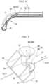
- FIG. 1is an overall view of a surgical instrument 1 according to an embodiment.
- Fig. 2is a schematic view showing a cartridge unit of the surgical instrument 1 seen in an arrow A direction shown in Fig. 1 .
- Fig. 3is a cross-sectional view taken along line III-III of Fig. 2 .
- Fig. 4is a partial cross-sectional view of the cartridge unit seen in an arrow B direction shown in Fig. 1 .
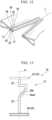
- Fig. 5is a perspective view showing an actuation section installed at the cartridge unit.
- Fig. 6is a side view of the actuation section.
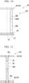
- Fig. 7is a perspective view showing a second jaw of the cartridge unit.
- Fig. 8is a cross-sectional view taken along line VIII-VIII of Fig. 7 .
- the surgical instrument 1is a medical tool configured to suture tissue using staples 27 (see Fig. 12 ) and to dissect the sutured area.
- the surgical instrument 1includes an insertion section 62 which is capable of being inserted into a body, and a manipulation unit 63 connected to the insertion section 62.
- the insertion section 62includes a cartridge unit 2 and a flexible tube 61.
- the cartridge unit 2is filled with staples 27.
- the flexible tube 61is connected to the cartridge unit 2.
- the cartridge unit 2has a root section 3, an open-close link section 8, a first jaw 10 and a second jaw 50.
- the root section 3is a substantially tubular area configured to connect the cartridge unit 2 to the flexible tube 61.
- a proximal end of the root section 3is fixed to a distal end of the flexible tube 61.
- a distal end of the root section 3is connected to the open-close link section 8 and the second jaw 50.
- a connecting member 5is inserted into the root section 3.
- the connecting member 5is operated by manipulation of a user with respect to the manipulation unit 63.
- the connecting member 5has a first connecting member 6 and a second connecting member 7 (a wire).
- the first connecting member 6is provided to open and close the first jaw 10 with respect to the second jaw 50.
- the second connecting member 7is provided to operate an actuation section 31, which will be described below.
- a proximal end of the first connecting member 6extends to the manipulation unit 63.
- a distal end of the first connecting member 6is connected to the open-close link section 8.
- the second connecting member 7has a dissection connecting member 7a and a returning connecting member 7b.
- the dissection connecting member 7ais wound on a pulley section 25, which will be described below.
- the dissection connecting member 7ais inserted into a first guide section 24, which will be described below.
- a proximal end of the dissection connecting member 7aextends to the manipulation unit 63.
- a distal end of the returning connecting member 7bis connected to the actuation section 31.
- the distal end of the returning connecting member 7bis connected to a proximal end of a shaft body 32, which will be described below.
- a proximal end of the returning connecting member 7bextends to the manipulation unit 63.
- the open-close link section 8is disposed at an inside of a distal portion of the root section 3 shown in Fig. 2 .
- the open-close link section 8has a link structure configured to convert movement of the first connecting member 6 in a center axis direction of the first connecting member 6 into open-close movement of the first jaw 10.
- the first jaw 10 shown in Figs. 2, 3 and 4is provided at a distal end portion of the insertion section 62 (see Fig. 1 ) to grasp tissue. As shown in Fig. 2 , the first jaw 10 has a predetermined curved shape.
- the first jaw 10has a base section 11, a staple holder 15, the staples 27 and the actuation section 31.
- the base section 11is a substantially rod-shaped or channel-shaped member having a longitudinal axis and a shape conforming to a curved shape of the first jaw 10.
- the base section 11has a concave section 12, and a communication path 13 to the root section 3.
- the concave section 12is capable of accommodating the staple holder 15 and the actuation section 31.
- the concave section 12is opened toward a second grasping surface 51 of the second jaw 50.
- a bottomis formed at the concave section 12 by a cover 14.
- the communication path 13 to the root section 3is a passage through which the second connecting member 7 is inserted.
- the staple holder 15has a holder main body 16, the pulley section 25 and a driver 26.
- the holder main body 16has a first grasping surface 17, an accommodating section 18 and a groove section 22.
- the first grasping surface 17comes in contact with tissue when the tissue is grasped.
- the staples 27are accommodated in the accommodating section 18.
- the groove section 22is opened at the first grasping surface 17.
- the holder main body 16is attached to the concave section 12 of the base section 11 in a direction in which the first grasping surface 17 is exposed from the base section 11.
- the staple holder 15is detachably attached to the base section 11. For example, after suture by using the staples 27, the staple holder 15 after use is capable of being removed from the base section 11. A suturation by using the surgical instrument 1 according to the embodiment is performed a plurality of times by attaching the staple holder 15 to the base section 11 in place of the used staple holders after suture by using the staples 27.
- the first grasping surface 17is a surface directed toward the second grasping surface 51 (see Fig. 1 ) of the second jaw 50 in a state in which the holder main body 16 is attached to the concave section 12 of the base section 11.
- the staples 27is capable of being accommodated in the accommodating section 18 in a state in which insertion ends of the staples 27 are directed toward the second grasping surface 51.
- an inner region of an envelope curve that surrounds the plurality of accommodating sections 18defines a suture area SA in which tissue is sutured by the staples 27.
- staple arrays 19a first staple array 20, a second staple array 21
- staple arrays 19are provided in two regions of the holder main body 16 divided by the groove section 22.
- the first staple array 20is constituted by the plurality of staples 27 arranged in an extending direction of the groove section 22.
- the first staple array 20is installed on the first grasping surface 17 in two or more rows at an interval.
- the second staple array 21is constituted by the plurality of staples 27 arranged in the extending direction of the groove section 22.
- the second staple array 21is installed on the first grasping surface 17 in two or more rows at an interval.
- the staple array 19has the plurality of staples 27, which is capable of being shot from the first jaw 10 toward the second jaw 50, around the groove section 22.
- the groove section 22is a linear groove in which a blade section 39 (to be described below) of the actuation section 31 is accommodated to be capable of advancing and retracting.
- the groove section 22is formed in a curved shape.
- the groove section 22defines a dissection line L (see Figs. 9 and 12 ) in dissection of tissue.
- the groove section 22has a through-hole 23 and the first guide section 24.
- the through-hole 23is opened at the first grasping surface 17.
- the first guide section 24is continuous with the through-hole section 23 and is formed in the holder main body 16.
- the through-hole section 23has a first wall surface 23a and a second wall surface 23b that are apart from each other, and a bottom surface that connects the first wall surface 23a and the second wall surface 23b.
- a bottom surface of the groove section 22is constituted by a part of an inner surface of the base section 11. Further, in the embodiment, in an intermediate region of the first jaw 10 in the extending direction of the groove section 22, gaps between the first wall surface 23a and the bottom surface and between the second wall surface 23b and the bottom surface are formed at an intermediate region of the first jaw 10 in the extending direction of the groove section 22 for allowing the actuation section 31 to pass through the intermediate region.
- the first wall surface 23ahas a surface crossing the first grasping surface 17 in the holder main body 16.
- the first wall surface 23aextends from the first grasping surface 17 of the holder main body 16 toward a bottom section of the concave section 12 of the base section 11.
- the first wall surface 23aextends in a longitudinal axis direction of the base section 11.
- the second wall surface 23bis a surface formed in parallel to the first wall surface 23a (including substantially in parallel) at a position apart from the first wall surface 23a by a distance at which the blade section 39 of the actuation section 31 is capable of passing therethrough.
- the second wall surface 23bis a surface crossing the first grasping surface 17 in the holder main body 16.
- the second wall surface 23bextends from the first grasping surface 17 of the holder main body 16 toward the bottom section of the concave section 12 of the base section 11.
- the second wall surface 23bextends in the longitudinal axis direction of the base section 11.
- the first guide section 24has a groove shape wider than an interval between the first wall surface 23a and the second wall surface 23b.
- the first guide section 24extends to conform to a curved shape of the groove section 22.
- a first guided section 34 of a pair of guided sections 33 formed at the actuation section 31is capable of coming in contact with the first guide section 24.
- the dissection connecting member 7ais inserted into the first guide section 24.
- the dissection connecting member 7aextends from a proximal end portion toward a distal end portion of the first guide section 24 along the first guide section 24, turns at the pulley section 25 of the distal end portion of the first guide section 24 to extend to the proximal end portion of the first guide section 24, and is connected to the actuation section 31.
- a distal end of the dissection connecting member 7ais wound on an outer periphery of the first guided section 34, which will be described below.
- the pulley section 25 shown in Fig. 4on which the dissection connecting member 7a is wound, is rotatably connected to the base section 11.
- the driver 26 shown in Fig. 3is disposed in the accommodating section 18.
- the driver 26is capable of being moved inside the accommodating section 18 by a cam section 37 of the actuation section 31. That is, when the driver 26 is moved toward an opening of the first grasping surface 17 side of the accommodating section 18 by the cam section 37 (see Fig. 5 ), the driver 26 pushes a connecting section 30 (see Fig. 12 ) of each of the staples 27 toward the opening of the first grasping surface 17 side to push out the staple 27 from the accommodating section 18.
- the staple 27has a pair of leg sections 28 and 29 (see Fig. 12 ) having insertion ends inserted into tissue, and the connecting section 30 that connects the pair of leg sections 28 and 29.
- the staple 27is formed in a U shape (a U shape in which all angles are right angles) by bending deformable strands having high biocompatibility.
- a known structuremay be selected and employed as the shape of the staple 27.
- the actuation section 31 shown in Figs. 3 , 5 and 6is disposed inside the base section 11.
- the actuation section 31is configured to move the driver 26 to push out the staples 27 from the accommodating section 18 and also dissect the tissue after the staples 27 are pushed out.
- the actuation section 31has the shaft body 32, the pair of guided sections 33, the cam section 37 and the blade section 39.
- the shaft body 32is connected to the distal end of the second connecting member 7 of the connecting member 5.
- the shaft body 32is capable of being guided and moved to a second guide section 53 (see Fig. 7 ) formed at the first guide section 24 and the second grasping surface 51, which will be described below, by moving the second connecting member 7 in a center axis direction of the second connecting member.
- a centerline C1 (see Fig. 6 ) of the shaft body 32is a rotational center of the actuation section 31 in the embodiment. That is, in the embodiment, the actuation section 31 is rotatable within a predetermined range about the centerline C1 of the shaft body 32 serving as a rotational center while being supported by the first guide section 24 and the second guide section 53.
- the allowable range of rotation of the actuation section 31 in the embodimentis between a state in which the blade section 39 comes in contact with the first wall surface 23a and a state in which the blade section 39 comes in contact with the second wall surface 23b.
- the pair of guided sections 33, the cam section 37 and the blade section 39are attached to the shaft body 32.
- the pair of guided sections 33are members engaged with the first guide section 24 and the second guide section 53.
- the pair of guided sections 33have the first guided section 34 engaged with the first guide section 24 and a second guided section 35 engaged with the second guide section 53.
- the first guided section 34is fixed to an end disposed at the first jaw 10 side, in both ends of the shaft body 32.
- the first guided section 34has a disk shape having a centerline in a thickness direction of the first guided section.
- a groove to which a distal end of the dissection connecting member 7a is hookedis formed to extend in the circumferential direction at an outer periphery of the first guided section 34.
- a distal end portion of the dissection connecting member 7ais annularly hooked to the first guided section 34.
- the first guided section 34is rotatable with respect to the distal portion of the dissection connecting member 7a.
- a centerline of the first guided section 34is coaxial with the centerline C1 of the shaft body 32.
- the first guided section 34is rotatable in the first guide section 24 together with the shaft body 32.
- the first guided section 34is attached to the shaft body 32 by a screw 34a.
- the first guided section 34 and the shaft body 32may be integrally formed.
- the second guided section 35is fixed to an end disposed at the second jaw 50 side, in both ends of the shaft body 32.
- the second guided section 35has a disk shape having a centerline in a thickness direction the second guided section.
- the centerline of the second guided section 35is coaxial with the centerline C1 of the shaft body 32.
- the second guided section 35is rotatable in the second guide section 53 together with the shaft body 32.
- the second guided section 35is attached to the shaft body 32 by a screw 35a.
- the second guided section 35 and the shaft body 32may be integrally formed.
- the cam section 37is connected to the shaft body 32 to be rotatable with respect to the shaft body 32.
- the cam section 37has an inclined surface 38 inclined with respect to a longitudinal axis of the base section 11.
- the inclined surface 38 of the cam section 37comes in contact with the driver 26 to move the driver 26 when the cam section 37 is moved in the longitudinal axis direction of the base section 11.
- the moving direction of the cam section 37is an extending direction of the groove section 22.
- the blade section 39is disposed at a position apart from the shaft body 32 in a direction crossing the direction in which the centerline C1 of the shaft body 32 extends.
- the blade section 39is connected to the shaft body 32 at a position between the ends of the shaft body 32.
- the blade section 39has a blade edge 39a extending in parallel to the centerline C1 of the shaft body 32.
- the blade edge 39ahas a sharp shape that is capable of dissecting tissue of a living body.
- the blade section 39is disposed at the groove section 22 so as to protrude from the first grasping surface 17 toward the second jaw 50.
- the blade section 39is positioned closer to the proximal side than the cam section 37 when the blade section 39 is positioned closest to the groove section 22 by rotation of the actuation section 31, which will be described below.
- the blade edge 39ais in a position apart from the centerline C1 of the shaft body 32 and directed toward the shaft body 32. For this reason, the blade section 39 is capable of dissectiong tissue while being pressed to a proximal side in a dissection direction of the tissue by the blade section 39 by which the blade edge 39a comes in contact with the tissue of the living body.
- the blade section 39is rotated about the centerline C1 of the shaft body 32 (serving as a rotational center of the actuation section 31 in the embodiment).
- the blade edge 39ais formed in at least a gap portion between the first grasping surface 17 and the second grasping surface 51.
- the second jaw 50 shown in Figs. 1 and 7is provided at a distal end portion of the insertion section 62 to grasp the tissue, and have a predetermined curved shape same as the first jaw 10.
- the second jaw 50has the second grasping surface 51 in which a plurality of forming pockets 52 is formed.
- the second grasping surface 51is a surface directed toward the first grasping surface 17 of the first jaw 10.
- a distance between the first grasping surface 17 of the first jaw 10 and the second grasping surface 51 of the second jaw 50is previously set according to a thickness of tissue serving as a suture target.
- the distance between the first grasping surface 17 of the first jaw 10 and the second grasping surface 51 of the second jaw 50is set to a distance at which adhesion of the tissue serving as a suture target occurs after suture by using the staples 27 and excessive debridement of the tissue serving as the suture target is hard to occur.
- the forming pockets 52 and the second guide section 53are formed at the second grasping surface 51.
- the second guide section 53is formed such that the second guided section 35 is capable of entering and to extend in the longitudinal axis direction of the second jaw 50.
- Each of the forming pockets 52 shown in Fig. 7has an inclined surface or a curved surface configured to guide the leg sections 28 and 29 to plastically deform the leg sections 28 and 29 of the staple 27 to form a shape in which the tissue is sutured as shown in Fig. 12 .
- the second guide section 53has an opening section 53a through which the shaft body 32 shown in Fig. 6 is capable of being inserted, and a groove section 53b wider than the opening section 53a and in which the second guided section 35 is slidable.
- the second guide section 53has a linear shape along a curved shape of the groove section 22 (see Figs. 2 and 3 ).
- a shape of the groove section 53bis appropriately set according to the shape of the second guided section 35.
- An inlet 53c configured to allow the second guided section 35 to enter the second guide section 53is formed at a proximal portion of the second guide section 53. For this reason, when the actuation section 31 is positioned closest to the proximal side with respect to the groove section 22, the second guided section 35 is removed from the second guide section 53. Accordingly, when the actuation section 31 is positioned closest to the proximal side with respect to the groove section 22, the first jaw 10 and the second jaw 50 is capable of being freely opened and closed in a state in which they are not connected by the actuation section 31.
- a suture unit 54 in which the tissue is sutured(see Fig. 3 ) is constituted by the staple holder 15, the staples 27, the cam section 37 and the second jaw 50.
- the flexible tube 61is a tubular elongated member.
- the connecting member 5(the first connecting member 6, the dissection connecting member 7a and the returning connecting member 7b) is inserted through the flexible tube 61.
- a proximal end of the root section 3 of the cartridge unit 2is fixed to a distal end of the flexible tube 61.
- the proximal end of the flexible tube 61is fixed to the manipulation unit 63.
- a pipe lineconfigured to guide a known observation apparatus (for example, an endoscope) for observing a suture area from the manipulation unit 63 toward the cartridge unit 2 may be installed at the flexible tube 61.
- a known observation apparatusfor example, an endoscope
- the manipulation unit 63is provided at the proximal end of the flexible tube 61.
- the manipulation unit 63is provided to allow a user to perform manipulation of opening and closing the first jaw 10 and the second jaw 50 to staple the staples 27 to the tissue, and to dissect the tissue.
- the manipulation unit 63has substantially a rod shape such that an operator is capable of gripping the manipulation unit 63 with her or his hands.
- the manipulation unit 63has a housing 64, a curved knob 65, an open-close knob 66, a lever 67, and a transmission mechanism (not shown).
- the housing 64has substantially a rod shape and is formed a space inside the housing.
- the curved knob 65is provided to bend the flexible tube 61.
- the open-close knob 66 and the lever 67are disposed to be exposed to the outside of the housing 64 to operate the connecting member 5.
- the transmission mechanismis connected to the connecting member 5 in the housing 64.
- the curved knob 65is a member configured to bend the flexible tube 61 by pulling an angle wire (not shown) extending from the distal end of the flexible tube 61 to the manipulation unit 63.
- the curved knob 65is rotatable with respect to the housing 64 of the manipulation unit 63, and is capable of being fixed not to be rotated with respect to the housing 64 at an arbitrary position.
- the open-close knob 66is a member configured to advance and retract the first connecting member 6 in the centerline direction.
- the open-close knob 66is rotatable with respect to the housing 64 of the manipulation unit 63, and is capable of being fixed not to be rotated with respect to the housing 64 at an arbitrary position.
- the transmission mechanism(not shown) transmits an amount of manipulation of the open-close knob 66 to the first connecting member 6 as an amount of force to advance and retract the first connecting member 6 in the centerline direction.
- the lever 67is a member configured to advance and retract the second connecting member 7 in the centerline direction.
- the lever 67is swingable with respect to the housing 64 of the manipulation unit 63, and in capable of being fixed not to be swung with respect to the housing 64 at an arbitrary position.
- the transmission mechanism(not shown) transmits an amount of manipulation of the lever 67 to the second connecting member 7 as an amount of force to advance and retract the second connecting member 7 in the centerline direction.
- the dissection connecting member 7ais pulled to the proximal side when the lever 67 is swung in one predetermined direction
- the returning connecting member 7bis pulled to the proximal side when the lever 67 is swung in a direction opposite to the one predetermined direction.
- the dissection connecting member 7a and the returning connecting member 7bare connected via the actuation section 31 in the cartridge unit 2. For this reason, the returning connecting member 7b is moved to the distal side when the dissection connecting member 7a is pulled to the proximal side by the lever 67, and the dissection connecting member 7a is moved to the distal side when the returning connecting member 7b is pulled to the proximal side by the lever 67.
- FIGs. 9 to 12are views showing the action of the surgical instrument 1 according to the embodiment.
- the surgical instrument 1is prepared in a state in which the staples 27 are accommodated in the accommodating section 18 and the cam section 37 and the blade section 39 are disposed in the vicinity of the proximal end of the base section 11.
- the pair of guided sections 33 of the actuation section 31are disposed in the vicinity of the proximal ends of the first guide section 24 and the second guide section 53.
- the surgical instrument 1is guided to a treatment target area through a natural opening of a patient such as the mouth or the like of the patient, a small incision portion formed in an abdominal wall or the like of the patient by a known technology.
- the first jaw 10 and the second jaw 50 provided at the distal end portion of the insertion section 62 of the surgical instrument 1grasp the tissue serving as the dissection target in accordance with a manipulation of the open-close knob 66 (see Fig. 1 ) of the manipulation unit 63 under observation of a laparoscope (not shown).
- the dissection line L with respect to the dissection target tissueis defined.
- a position of the first jaw 10 with respect to the second jaw 50is fixed in a state in which the first jaw 10 and the second jaw 50 grasp the tissue.
- the useroperates the lever 67 to move the dissection connecting member 7a to the proximal side after fixing the open-close knob 66 shown in Fig. 1 to the housing 64.
- the dissection connecting member 7a moved to the proximal sidemoves the actuation section 31 to the distal side as a pulling direction is reversed by the pulley section 25 shown in Fig. 4 .
- the actuation section 31moves both of the cam section 37 and the blade section 39 shown in Figs. 3 and 5 to the distal side.
- the driver 26 shown in Fig. 3is pushed up by the inclined surface 38 of the cam section 37 which is moved to the distal side.
- the driver 26 shown in Fig. 3pushes out the staples 27 from the accommodating section 18 such that insertion ends of the staples 27 pierce into the tissue as the driver 26 is pushed up to the inclined surface 38 of the actuation section 31.
- the leg sections 28 and 29 of the staples 27abut the forming pockets 52 (see Fig. 7 ).
- the forming pockets 52deform the leg sections 28 and 29 of the staples 27 into a predetermined shape for suturing the tissue as shown in Fig. 12 .
- the staples 27are sequentially shot from the accommodating section 18 from the proximal side toward the distal side of the first jaw 10 in accordance with a movement of the cam section 37.
- the suture unit 54 shown in Fig. 3sutures the tissue grasped by the first jaw 10 and the second jaw 50 via the staples 27.
- the actuation section 31is capable of being moved along the groove section 22 by the second connecting member 7.
- the blade section 39(see Figs. 5 and 6 ) disposed at the proximal side of the cam section 37 moves along the groove section 22 between the first staple array 20 and the second staple array 21 serving as the dissection line L (see Figs. 9 and 12 ) as the blade section 39 is pulled by the dissection connecting member 7a.
- the actuation section 31is pulled by the dissection connecting member 7a and dissects the tissue of the living body, the blade edge 39a is pressed against the tissue, and the actuation section 31 rotates about a centerline of each of the pair of guided sections 33 serving as a rotational center.
- the blade edge 39a of the blade section 39comes in contact with neither the first wall surface 23a nor the second wall surface 23b of the groove section 22, the shaft body 32 rotates about the centerline of each of the pair of guided sections 33 serving as a rotational center due to rotation of the actuation section 31, and the blade section 39 rotates about the shaft body 32.
- the blade section 39is moved to a hand side (a proximal side of the groove section 22) in a moving direction of the actuation section 31 by rotation of the blade section 39, and a direction of the blade edge 39a is a pulling direction of the actuation section 31 by the dissection connecting member 7a.
- the blade edge 39ais directed in the pulling direction of the actuation section 31 by the dissection connecting member 7a.
- the blade edge 39ais directed in a tangential direction of the curved groove section 22.
- the tissueis sequentially dissected by the blade section 39 from an area sutured by the staples 27.
- the blade section 39dissects the tissue in the suture area SA, in the tissue grasped by the first jaw 10 and the second jaw 50.
- the userAfter completion of suture by the staples 27 and dissection by the blade section 39, the user releases fixing of a lever 69 by a fixing section 70 and opens the first jaw 10 with respect to the second jaw 50. Accordingly, grasping of the tissue by the first jaw 10 and the second jaw 50 is released.
- the actuation section 31is capable of moving to the proximal end side of the groove section 22 by which the returning connecting member 7b is moved to the proximal side by operating the lever 67.
- the empty staple holder 15 after shooting of the staples 27is capable of replacing with a new staple holder 15.
- suture and dissectionare capable of continuously performing by replacing the staple holder 15 with a new one after shooting the staples 27 to continue suture and dissection.
- the blade sectionmay unsteadily move when the tissue is pushed out from the proximal side of the blade section.
- a direction in which a compressive force is applied to the blade sectionshould be adjusted in an advance direction of the blade section.
- the surgical instrument 1 of the embodimentsince the blade edge 39a of the blade section 39 is directed toward the distal side of the groove section 22 in the tangential direction of the groove section 22 by which the actuation section 31 having the blade section 39 is pulled by the dissection connecting member 7a, unsteadily movement of the blade section 39 is hard to occur, movement of the blade section 39 is smoothly performed, and dissection of the tissue is stabilized.
- Fig. 13is a side view showing an actuation section 1A of a surgical instrument according to the embodiment.
- the surgical instrument 1A according to the embodimentis different from the first embodiment in that a blade section 39A has a blade edge 39aA extending to be inclined with respect to the centerline C1 of the shaft body 32.
- the blade edge 39aAis formed along a straight line crossing the centerline C1 of the shaft body 32. In the blade edge 39aA, half or more of the entire length of the blade edge 39aA is directed toward the centerline C1 of the shaft body 32.
- the blade edge 39aAextends in a direction inclined with respect to an advance direction of the blade edge 39aA. For this reason, the tissue of the living body is capable of being dissected with a force smaller than that of the blade edge 39a described in the first embodiment.
- FIG. 14is a side view showing an actuation section 1B of a surgical instrument according to the embodiment.
- an actuation section 31B having a different configuration different from the actuation section 31 described in the first embodimentis provided instead of the actuation section 31 described in the first embodiment.
- the actuation section 31Bis different from the first embodiment in that a shaft body 32B is fixed to a position offset with respect to a centerline of each of the pair of guided sections 33, instead of the shaft body 32 described in the first embodiment.
- the actuation section 31Brotates about a centerline C2 of each of the pair of guided sections 33.
- the shaft body 32Brotates about the centerline C2 each of the pair of guided sections 33 serving as a rotational center due to rotation of the actuation section 31B about the centerline C2 of each of the pair of guided sections 33 serving as a rotational center.
- a blade section 39Bconfigured to dissect the tissue of the living body like the first embodiment is provided at the shaft body 32B.
- the blade section 39Bhas a blade edge 39aB directed to a centerline of each of the pair of guided sections 33 extending parallel to a centerline of each of the pair of guided sections 33.
- the actuation section 31Bis movable along the groove section 22 by the second connecting member 7.
- the tissuepushes the blade edge 39aB like the first embodiment, and the actuation section 31B rotates about the center line of each of the pair of guided sections 33 serving as a rotational center.
- the shaft body 32Brotates about a centerline of each of the pair of guided sections 33
- the blade section 39Brotates about a centerline of each of the pair of guided sections 33.
- the blade section 39moves to a hand side in the moving direction of the actuation section 31B (a proximal side of the groove section 22).
- the blade edge 39aBis directed in a pulling direction of the actuation section 31B by the dissection connecting member 7a. At this time, the blade edge 39aB is directed in a tangential direction of the curved groove section 22.
- FIG. 15is a cross-sectional view showing an actuation section 31C of a surgical instrument according to the embodiment.
- the actuation section 31Chaving a different configuration from the actuation section 31 described in the first embodiment is provided instead of the actuation section 31 described in the first embodiment.
- the actuation section 31Cis different from the first embodiment in that the shaft body 32 is connected to the pair of guided sections 33 such that the shaft body 32 is rotatable with respect to the pair of guided sections 33.
- a bearing 34c interposed between the first guided section 34 and the shaft body 32 and a bearing 35c interposed between the second guided section 35 and the shaft body 32are provided.
- the blade section 39in addition to rotation of the actuation section 31C as a whole, the blade section 39 is rotatable when the shaft body 32 is rotated with respect to the first guided section 34 and the second guided section 35 as well. In the embodiment, the blade section 39 is rotatable with a force smaller than that in the first embodiment.
- Fig. 16is a side view showing an actuation section 31D of a surgical instrument according to the embodiment.
- Fig. 17is a cross-sectional view showing configurations of the first guide section 24 and the second guide section 53 of the surgical instrument according to the embodiment, and showing the same cross section taken along line III-III of Fig. 2 .
- the actuation section 31Dhaving a different configuration from the actuation section 31 described in the first embodiment is provided instead of the actuation section 31 described in the first embodiment.
- the actuation section 31Dhas a pair of guided sections 33D (a first guided section 34D, a second guided section 35D) of which a surface directed to the shaft body 32 formes a curved surface, instead of the pair of guided sections 33 of the first embodiment.
- the surface directed toward the shaft body 32is formed in a curved surface protruding toward the shaft body 32 (a hemispherical shape in the embodiment), and the surface directed toward the shaft body 32 is a sliding surface that comes in point contact with the first guide section 24.
- the surface directed toward the shaft body 32is formed in a curved surface shape protruding toward the shaft body 32 (a hemispherical shape in the embodiment), and the surface directed toward the shaft body 32 is a sliding surface in point contact with the second guide section 53.
- first guide section 24 and the second guide section 53have inclined surfaces 24D and 53D that are inclined in a V shape respectively.
- the first guided section 34D and the second guided section 35Dcome in point contact with the inclined surface 24D and the inclined surface 53D.
- FIG. 18is a schematic view showing an actuation section 31E and a first guide section 24 of a surgical instrument according to the embodiment.
- the actuation section 31Ehaving a different configuration from the actuation section 31 described in the first embodiment is provided instead of the actuation section 31 described in the first embodiment.
- the actuation section 31Ehas a first guided section 34E having an elliptical disk shape, instead of the first guided section 34 of the first embodiment.
- the first guided section 34Ehas a longitudinal axis larger than a width w1 of the first guide section 24 and a short axis slightly smaller than the width w1 of the first guide section 24.
- the actuation section 31Eis assembled upon assembly of the first jaw 10 such that the blade section 39 is disposed closer to a proximal side than the shaft body 32 when the first guided section 34E enters the first guide section 24. For this reason, a rotatable range of the actuation section 31E is limited to a range in which the first guided section 34E is rotatable in the first guide section 24. A stopper structure constituted by the first guided section 34E abuts onto the first guide section 24 to restrict that the shaft body 32 rotates 180° or more with respect to the first guide section 24.
- a second guided section(not shown) having an elliptical disk shape may be provided instead of the second guided section 35 of the first embodiment.
- Fig. 19is a cross-sectional view showing configurations of an actuation section 31F, a first guide section 24F and a second guide section 53F of a surgical instrument according to the embodiment, and showing the same cross section taken along line III-III of Fig. 2 .
- the first guide section 24F and the second guide section 53F having different configurations from the first guide section 24 and the second guide section 53 described in the first embodimentare provided instead of the first guide section 24 and the second guide section 53 described in the first embodiment.
- the actuation section 31F having a different configuration from the actuation section 31 described in the first embodimentis provided instead of the actuation section 31 described in the first embodiment.
- the first guide section 24Fhas a wall section 24Fa and a wall section 24Fb having different heights at an inner periphery side and an outer periphery side of the curved shape of the groove section 22.
- the second guide section 53Fhas a wall section 53Fa and a wall section 53Fb having different heights at an inner periphery side and an outer periphery side of the curved shape of the groove section 22.
- the actuation section 31Fhas a pair of guided sections 33F constituted by a first guided section 34F and a second guided section 35F, instead of the pair of guided sections 33 described in the first embodiment.
- the first guided section 34Fhas a first inner rotation member 40 rotatable with respect to the shaft body 32, a first outer rotation member 41 coaxial with the first inner rotation member 40 and connected to the first inner rotation member 40, and a pulley plate 42 connected to the dissection connecting member 7a like the first embodiment.
- the first inner rotation member 40 and the first outer rotation member 41are relatively rotatable about the centerline C1 of the shaft body 32 serving as a rotational center.
- the first inner rotation member 40is capable of abutting the wall section 24Fa at the inner periphery side of the curved shape of the groove section 22, in the wall section 24Fa and the wall section 24Fb.
- the first outer rotation member 41is capable of abutting the wall section 24Fb at the outer periphery side of the curved shape of the groove section 22, in the wall section 24Fa and the wall section 24Fb.
- the second guided section 35Fhas a second inner rotation member 43 that is rotatable with respect to the shaft body 32, and a second outer rotation member 44 coaxial with the second inner rotation member 43 and connected to the second inner rotation member 43.
- the second inner rotation member 43 and the second outer rotation member 44are relatively rotatable about the centerline C1 of the shaft body 32 serving as a rotational center.
- the second inner rotation member 43is capable of abutting the wall section 53Fa at the inner periphery side of the curved shape of the groove section 22, in the wall section 53Fa and the wall section 53Fb.
- the second outer rotation member 44is capable of abutting the wall section 53Fb at the outer periphery side of the curved shape of the groove section 22, in the wall section 53Fa and the wall section 53Fb.
- the first inner rotation member 40 and the first outer rotation member 41is capable of being rotated in opposite directions
- the second inner rotation member 43 and the second outer rotation member 44is capable of being rotated in opposite directions.
- the pair of guided sections 33Fare rolled with respect to the first guide section 24F and the second guide section 53F, and a resistance at this time is rolling friction smaller than sliding friction.
- the actuation section 31F and the blade section 39 thereofsmoothly advance along the groove section 22.
- a hard shaftmay be provided instead of the flexible tube 61.
- the jawsmay be configured such that an open-close operation in the cartridge unit 2 and dissection of the tissue by the blade section 39 of the actuation section 31 are performed as one operation.
- the actuation section 31when the actuation section 31 is moved to the distal side of the cartridge unit 2 by using the lever 67, the actuation section 31 may be configured to connect the first jaw 10 and the second jaw 50 to move the first jaw 10 toward the second jaw 50.
- the open-close operation in the cartridge unit 2 and dissection of the tissue by the blade section 39 of the actuation section 31may be performed as one operation using the lever 67.
- a surgical instrument in which movement of a blade section in a tissue dissection process is smoothcan be provided.
Landscapes
- Health & Medical Sciences (AREA)
- Life Sciences & Earth Sciences (AREA)
- Surgery (AREA)
- Heart & Thoracic Surgery (AREA)
- Engineering & Computer Science (AREA)
- Biomedical Technology (AREA)
- Nuclear Medicine, Radiotherapy & Molecular Imaging (AREA)
- Medical Informatics (AREA)
- Molecular Biology (AREA)
- Animal Behavior & Ethology (AREA)
- General Health & Medical Sciences (AREA)
- Public Health (AREA)
- Veterinary Medicine (AREA)
- Surgical Instruments (AREA)
Description
- The present invention relates to a surgical instrument.
- Priority is claimed on
Japanese Patent Application No. 2014-158526, filed August 4, 2014 - In the related art, a tool configured to simultaneously perform suture and dissection of living body tissue is known.
- For example, in
Patent Documents 1 and 2, surgical instruments including a cartridge in which a plurality of staples are accommodated, a blade section configured to dissect living body tissue, and a manipulation unit for dissecting the tissue using the blade section and shooting staples into the tissue are disclosed. - In addition, in
Patent Document 2, a surgical instrument capable of moving a blade section along a cartridge having a curved shape is disclosed. - As a further example,
Patent Document 3 discloses a suturing device comprising an insertion portion, an operation portion provided at the proximal end of the insertion portion, and a suturing portion having an anvil acting as a staple deforming means for receiving and deforming a staple. A cutter is connected to the inside of a cartridge holder provided on the upper surface of a drive pulley. In particular, the drive pulley is slidably provided in a slit-like pulley guide provided along a center line of the cartridge holder and is configured to slide toward the front end side of the cartridge. The cutter is configured to slide in a cutter groove between a plurality of staple rows that are fixed to a tissue so as to cut the tissue. Then, once the tissue is cut, both the cutter and the pulley are simultaneously pulled back to the rear portion of the cartridge. - Published Japanese Translation No.
2013-542004 of PCT International Publication - [Patent Document 2]
Japanese Unexamined Patent Application, First Publication No. H08-289895 - [Patent Document 3]
Japanese Patent Application Publication No.JP H08 289895 A - In the surgical instrument of the related art, in a case that a blade section is moved along a curved shape of a cartridge, the blade section is pushed and moved from a proximal side of the blade section, a push-out direction of the blade section may not be stabilized and the blade section may move unsteadily. When the blade section the blade moves unsteadily, since movement of the blade section is not smooth, dissection of tissue becomes unstable.
- In consideration of the above-mentioned circumstances, the present invention is directed to provide a surgical instrument in which movement of a blade section is smooth in a process of dissecting tissue.
- The present invention is defined by the appended claims.
- According to the present invention, it is possible to provide a surgical instrument in which movement of the blade section is smooth in a process of dissecting tissue.
Fig. 1 is an overall view of a surgical instrument according to a first embodiment of the present invention.Fig. 2 is a schematic view showing a cartridge unit of the surgical instrument according to the first embodiment of the present invention.Fig. 3 is a cross-sectional view taken along line III-III ofFig. 2 .Fig. 4 is a partial cross-sectional view of the cartridge unit of the first embodiment of the present invention.Fig. 5 is a perspective view showing an actuation section installed at the cartridge unit of the first embodiment of the present invention.Fig. 6 is a side view of the actuation section of the first embodiment of the present invention.Fig. 7 is a perspective view showing a second jaw of the cartridge unit of the first embodiment of the present invention.Fig. 8 is a cross-sectional view taken along line VIII-VIII ofFig. 7 .Fig. 9 is a view showing an action of the surgical instrument according to the first embodiment of the present invention.Fig. 10 is a view showing an action of the surgical instrument according to the first embodiment of the present invention.Fig. 11 is a view showing an action of the surgical instrument according to the first embodiment of the present invention.Fig. 12 is a view showing an action of the surgical instrument according to the first embodiment of the present invention.Fig. 13 is a side view showing an actuation section of a surgical instrument according to a second embodiment of the present invention.Fig. 14 is a side view showing an actuation section of a surgical instrument according to a third embodiment of the present invention.Fig. 15 is a side view showing an actuation section of a surgical instrument according to a fourth embodiment of the present invention.Fig. 16 is a side view showing an actuation section of a surgical instrument according to a fifth embodiment of the present invention.Fig. 17 is a cross-sectional view showing configurations of a first guide section and a second guide section of the surgical instrument according to the fifth embodiment of the present invention, and showing the same cross section as taken along line III-III ofFig. 2 .Fig. 18 is a schematic view showing an actuation section and a first guide section of a surgical instrument according to a sixth embodiment of the present invention.Fig. 19 is a cross-sectional view showing configurations of an actuation section, a first guide section and a second guide section of a surgical instrument according to a seventh embodiment of the present invention, and showing the same cross section as taken along line III-III ofFig. 2 .- A first embodiment of the present invention will be described.
Fig. 1 is an overall view of a surgical instrument 1 according to an embodiment.Fig. 2 is a schematic view showing a cartridge unit of the surgical instrument 1 seen in an arrow A direction shown inFig. 1 .Fig. 3 is a cross-sectional view taken along line III-III ofFig. 2 .Fig. 4 is a partial cross-sectional view of the cartridge unit seen in an arrow B direction shown inFig. 1 .Fig. 5 is a perspective view showing an actuation section installed at the cartridge unit.Fig. 6 is a side view of the actuation section.Fig. 7 is a perspective view showing a second jaw of the cartridge unit.Fig. 8 is a cross-sectional view taken along line VIII-VIII ofFig. 7 . - The surgical instrument 1 according to the embodiment shown in
Fig. 1 is a medical tool configured to suture tissue using staples 27 (seeFig. 12 ) and to dissect the sutured area. The surgical instrument 1 includes aninsertion section 62 which is capable of being inserted into a body, and amanipulation unit 63 connected to theinsertion section 62. Theinsertion section 62 includes acartridge unit 2 and aflexible tube 61. Thecartridge unit 2 is filled withstaples 27. Theflexible tube 61 is connected to thecartridge unit 2. - The
cartridge unit 2 has aroot section 3, an open-close link section 8, afirst jaw 10 and asecond jaw 50. - As shown in
Figs. 1 and2 , theroot section 3 is a substantially tubular area configured to connect thecartridge unit 2 to theflexible tube 61. A proximal end of theroot section 3 is fixed to a distal end of theflexible tube 61. A distal end of theroot section 3 is connected to the open-close link section 8 and thesecond jaw 50. - A connecting
member 5 is inserted into theroot section 3. The connectingmember 5 is operated by manipulation of a user with respect to themanipulation unit 63. - The connecting
member 5 has a first connectingmember 6 and a second connecting member 7 (a wire). The first connectingmember 6 is provided to open and close thefirst jaw 10 with respect to thesecond jaw 50. The second connectingmember 7 is provided to operate anactuation section 31, which will be described below. - A proximal end of the first connecting
member 6 extends to themanipulation unit 63. A distal end of the first connectingmember 6 is connected to the open-close link section 8. - As shown in
Fig. 4 , the second connectingmember 7 has adissection connecting member 7a and a returning connectingmember 7b. Thedissection connecting member 7a is wound on apulley section 25, which will be described below. Thedissection connecting member 7a is inserted into afirst guide section 24, which will be described below. A proximal end of thedissection connecting member 7a extends to themanipulation unit 63. - As shown in
Fig. 5 , a distal end of the returning connectingmember 7b is connected to theactuation section 31. In the embodiment, the distal end of the returning connectingmember 7b is connected to a proximal end of ashaft body 32, which will be described below. A proximal end of the returning connectingmember 7b extends to themanipulation unit 63. - The open-
close link section 8 is disposed at an inside of a distal portion of theroot section 3 shown inFig. 2 . The open-close link section 8 has a link structure configured to convert movement of the first connectingmember 6 in a center axis direction of the first connectingmember 6 into open-close movement of thefirst jaw 10. - The
first jaw 10 shown inFigs. 2, 3 and4 is provided at a distal end portion of the insertion section 62 (seeFig. 1 ) to grasp tissue. As shown inFig. 2 , thefirst jaw 10 has a predetermined curved shape. Thefirst jaw 10 has abase section 11, astaple holder 15, thestaples 27 and theactuation section 31. - As shown in
Fig. 3 , thebase section 11 is a substantially rod-shaped or channel-shaped member having a longitudinal axis and a shape conforming to a curved shape of thefirst jaw 10. Thebase section 11 has aconcave section 12, and acommunication path 13 to theroot section 3. Theconcave section 12 is capable of accommodating thestaple holder 15 and theactuation section 31. Theconcave section 12 is opened toward a second graspingsurface 51 of thesecond jaw 50. A bottom is formed at theconcave section 12 by a cover 14. As shown inFig. 4 , thecommunication path 13 to theroot section 3 is a passage through which the second connectingmember 7 is inserted. - As shown in
Fig. 3 , thestaple holder 15 has a holdermain body 16, thepulley section 25 and adriver 26. - The holder
main body 16 has a first graspingsurface 17, anaccommodating section 18 and agroove section 22. The first graspingsurface 17 comes in contact with tissue when the tissue is grasped. Thestaples 27 are accommodated in theaccommodating section 18. Thegroove section 22 is opened at the first graspingsurface 17. The holdermain body 16 is attached to theconcave section 12 of thebase section 11 in a direction in which the first graspingsurface 17 is exposed from thebase section 11. - The
staple holder 15 is detachably attached to thebase section 11. For example, after suture by using thestaples 27, thestaple holder 15 after use is capable of being removed from thebase section 11. A suturation by using the surgical instrument 1 according to the embodiment is performed a plurality of times by attaching thestaple holder 15 to thebase section 11 in place of the used staple holders after suture by using thestaples 27. - The first grasping
surface 17 is a surface directed toward the second grasping surface 51 (seeFig. 1 ) of thesecond jaw 50 in a state in which the holdermain body 16 is attached to theconcave section 12 of thebase section 11. - The
staples 27 is capable of being accommodated in theaccommodating section 18 in a state in which insertion ends of thestaples 27 are directed toward the second graspingsurface 51. - As shown in
Fig. 3 , in the first graspingsurface 17, an inner region of an envelope curve that surrounds the plurality ofaccommodating sections 18 defines a suture area SA in which tissue is sutured by thestaples 27. In a state in which thestaples 27 are accommodated in theaccommodating section 18, staple arrays 19 (a firststaple array 20, a second staple array 21) are provided in two regions of the holdermain body 16 divided by thegroove section 22. - The first
staple array 20 is constituted by the plurality ofstaples 27 arranged in an extending direction of thegroove section 22. In the embodiment, the firststaple array 20 is installed on the first graspingsurface 17 in two or more rows at an interval. - The second
staple array 21 is constituted by the plurality ofstaples 27 arranged in the extending direction of thegroove section 22. In the embodiment, the secondstaple array 21 is installed on the first graspingsurface 17 in two or more rows at an interval. - Accordingly, the
staple array 19 has the plurality ofstaples 27, which is capable of being shot from thefirst jaw 10 toward thesecond jaw 50, around thegroove section 22. - As shown in
Fig. 3 , thegroove section 22 is a linear groove in which a blade section 39 (to be described below) of theactuation section 31 is accommodated to be capable of advancing and retracting. In the embodiment, thegroove section 22 is formed in a curved shape. Thegroove section 22 defines a dissection line L (seeFigs. 9 and12 ) in dissection of tissue. - The
groove section 22 has a through-hole 23 and thefirst guide section 24. The through-hole 23 is opened at the first graspingsurface 17. Thefirst guide section 24 is continuous with the through-hole section 23 and is formed in the holdermain body 16. - The through-
hole section 23 has afirst wall surface 23a and asecond wall surface 23b that are apart from each other, and a bottom surface that connects thefirst wall surface 23a and thesecond wall surface 23b. In the embodiment, a bottom surface of thegroove section 22 is constituted by a part of an inner surface of thebase section 11. Further, in the embodiment, in an intermediate region of thefirst jaw 10 in the extending direction of thegroove section 22, gaps between thefirst wall surface 23a and the bottom surface and between thesecond wall surface 23b and the bottom surface are formed at an intermediate region of thefirst jaw 10 in the extending direction of thegroove section 22 for allowing theactuation section 31 to pass through the intermediate region. - As shown in
Fig. 3 , thefirst wall surface 23a has a surface crossing the first graspingsurface 17 in the holdermain body 16. Thefirst wall surface 23a extends from the first graspingsurface 17 of the holdermain body 16 toward a bottom section of theconcave section 12 of thebase section 11. Thefirst wall surface 23a extends in a longitudinal axis direction of thebase section 11. - As shown in
Fig. 3 , thesecond wall surface 23b is a surface formed in parallel to thefirst wall surface 23a (including substantially in parallel) at a position apart from thefirst wall surface 23a by a distance at which theblade section 39 of theactuation section 31 is capable of passing therethrough. Thesecond wall surface 23b is a surface crossing the first graspingsurface 17 in the holdermain body 16. Thesecond wall surface 23b extends from the first graspingsurface 17 of the holdermain body 16 toward the bottom section of theconcave section 12 of thebase section 11. Thesecond wall surface 23b extends in the longitudinal axis direction of thebase section 11. - As shown in
Figs. 3 and4 , thefirst guide section 24 has a groove shape wider than an interval between thefirst wall surface 23a and thesecond wall surface 23b. Thefirst guide section 24 extends to conform to a curved shape of thegroove section 22. A first guidedsection 34 of a pair of guidedsections 33 formed at theactuation section 31 is capable of coming in contact with thefirst guide section 24. - The
dissection connecting member 7a is inserted into thefirst guide section 24. In the inside of thefirst guide section 24, thedissection connecting member 7a extends from a proximal end portion toward a distal end portion of thefirst guide section 24 along thefirst guide section 24, turns at thepulley section 25 of the distal end portion of thefirst guide section 24 to extend to the proximal end portion of thefirst guide section 24, and is connected to theactuation section 31. In the embodiment, a distal end of thedissection connecting member 7a is wound on an outer periphery of the first guidedsection 34, which will be described below. - The
pulley section 25 shown inFig. 4 , on which thedissection connecting member 7a is wound, is rotatably connected to thebase section 11. - The
driver 26 shown inFig. 3 is disposed in theaccommodating section 18. Thedriver 26 is capable of being moved inside theaccommodating section 18 by acam section 37 of theactuation section 31. That is, when thedriver 26 is moved toward an opening of the first graspingsurface 17 side of theaccommodating section 18 by the cam section 37 (seeFig. 5 ), thedriver 26 pushes a connecting section 30 (seeFig. 12 ) of each of thestaples 27 toward the opening of the first graspingsurface 17 side to push out the staple 27 from theaccommodating section 18. - The staple 27 has a pair of
leg sections 28 and 29 (seeFig. 12 ) having insertion ends inserted into tissue, and the connectingsection 30 that connects the pair ofleg sections staple 27. - The
actuation section 31 shown inFigs. 3 ,5 and6 is disposed inside thebase section 11. Theactuation section 31 is configured to move thedriver 26 to push out thestaples 27 from theaccommodating section 18 and also dissect the tissue after thestaples 27 are pushed out. - As shown in
Figs. 3 ,5 and6 , theactuation section 31 has theshaft body 32, the pair of guidedsections 33, thecam section 37 and theblade section 39. - The
shaft body 32 is connected to the distal end of the second connectingmember 7 of the connectingmember 5. Theshaft body 32 is capable of being guided and moved to a second guide section 53 (seeFig. 7 ) formed at thefirst guide section 24 and the second graspingsurface 51, which will be described below, by moving the second connectingmember 7 in a center axis direction of the second connecting member. A centerline C1 (seeFig. 6 ) of theshaft body 32 is a rotational center of theactuation section 31 in the embodiment. That is, in the embodiment, theactuation section 31 is rotatable within a predetermined range about the centerline C1 of theshaft body 32 serving as a rotational center while being supported by thefirst guide section 24 and thesecond guide section 53. The allowable range of rotation of theactuation section 31 in the embodiment is between a state in which theblade section 39 comes in contact with thefirst wall surface 23a and a state in which theblade section 39 comes in contact with thesecond wall surface 23b. The pair of guidedsections 33, thecam section 37 and theblade section 39 are attached to theshaft body 32. - The pair of guided
sections 33 are members engaged with thefirst guide section 24 and thesecond guide section 53. In the embodiment, the pair of guidedsections 33 have the first guidedsection 34 engaged with thefirst guide section 24 and a second guidedsection 35 engaged with thesecond guide section 53. - The first guided
section 34 is fixed to an end disposed at thefirst jaw 10 side, in both ends of theshaft body 32. The first guidedsection 34 has a disk shape having a centerline in a thickness direction of the first guided section. A groove to which a distal end of thedissection connecting member 7a is hooked is formed to extend in the circumferential direction at an outer periphery of the first guidedsection 34. A distal end portion of thedissection connecting member 7a is annularly hooked to the first guidedsection 34. The first guidedsection 34 is rotatable with respect to the distal portion of thedissection connecting member 7a. In the embodiment, a centerline of the first guidedsection 34 is coaxial with the centerline C1 of theshaft body 32. The first guidedsection 34 is rotatable in thefirst guide section 24 together with theshaft body 32. The first guidedsection 34 is attached to theshaft body 32 by a screw 34a. The first guidedsection 34 and theshaft body 32 may be integrally formed. - The second guided
section 35 is fixed to an end disposed at thesecond jaw 50 side, in both ends of theshaft body 32. The second guidedsection 35 has a disk shape having a centerline in a thickness direction the second guided section. In the embodiment, the centerline of the second guidedsection 35 is coaxial with the centerline C1 of theshaft body 32. The second guidedsection 35 is rotatable in thesecond guide section 53 together with theshaft body 32. The second guidedsection 35 is attached to theshaft body 32 by a screw 35a. The second guidedsection 35 and theshaft body 32 may be integrally formed. - As shown in
Figs. 3 and5 , thecam section 37 is connected to theshaft body 32 to be rotatable with respect to theshaft body 32. Thecam section 37 has aninclined surface 38 inclined with respect to a longitudinal axis of thebase section 11. Theinclined surface 38 of thecam section 37 comes in contact with thedriver 26 to move thedriver 26 when thecam section 37 is moved in the longitudinal axis direction of thebase section 11. The moving direction of thecam section 37 is an extending direction of thegroove section 22. - As shown in
Fig. 6 , theblade section 39 is disposed at a position apart from theshaft body 32 in a direction crossing the direction in which the centerline C1 of theshaft body 32 extends. Theblade section 39 is connected to theshaft body 32 at a position between the ends of theshaft body 32. Theblade section 39 has ablade edge 39a extending in parallel to the centerline C1 of theshaft body 32. Theblade edge 39a has a sharp shape that is capable of dissecting tissue of a living body. As shown inFig. 3 , theblade section 39 is disposed at thegroove section 22 so as to protrude from the first graspingsurface 17 toward thesecond jaw 50. Theblade section 39 is positioned closer to the proximal side than thecam section 37 when theblade section 39 is positioned closest to thegroove section 22 by rotation of theactuation section 31, which will be described below. - The
blade edge 39a is in a position apart from the centerline C1 of theshaft body 32 and directed toward theshaft body 32. For this reason, theblade section 39 is capable of dissectiong tissue while being pressed to a proximal side in a dissection direction of the tissue by theblade section 39 by which theblade edge 39a comes in contact with the tissue of the living body. When theblade section 39 is pushed by the tissue of the living body, theblade section 39 is rotated about the centerline C1 of the shaft body 32 (serving as a rotational center of theactuation section 31 in the embodiment). - In the embodiment, when the
first jaw 10 and thesecond jaw 50 are in a closed state, theblade edge 39a is formed in at least a gap portion between the first graspingsurface 17 and the second graspingsurface 51. - The
second jaw 50 shown inFigs. 1 and7 is provided at a distal end portion of theinsertion section 62 to grasp the tissue, and have a predetermined curved shape same as thefirst jaw 10. Thesecond jaw 50 has the second graspingsurface 51 in which a plurality of formingpockets 52 is formed. - The second
grasping surface 51 is a surface directed toward the first graspingsurface 17 of thefirst jaw 10. When thefirst jaw 10 is closed with respect to thesecond jaw 50, a distance between the first graspingsurface 17 of thefirst jaw 10 and the second graspingsurface 51 of thesecond jaw 50 is previously set according to a thickness of tissue serving as a suture target. The distance between the first graspingsurface 17 of thefirst jaw 10 and the second graspingsurface 51 of thesecond jaw 50 is set to a distance at which adhesion of the tissue serving as a suture target occurs after suture by using thestaples 27 and excessive debridement of the tissue serving as the suture target is hard to occur. - The forming pockets 52 and the
second guide section 53 are formed at the second graspingsurface 51. Thesecond guide section 53 is formed such that the second guidedsection 35 is capable of entering and to extend in the longitudinal axis direction of thesecond jaw 50. - Each of the forming
pockets 52 shown inFig. 7 has an inclined surface or a curved surface configured to guide theleg sections leg sections Fig. 12 . - As shown in
Fig. 8 , thesecond guide section 53 has anopening section 53a through which theshaft body 32 shown inFig. 6 is capable of being inserted, and agroove section 53b wider than theopening section 53a and in which the second guidedsection 35 is slidable. As shown inFig. 7 , thesecond guide section 53 has a linear shape along a curved shape of the groove section 22 (seeFigs. 2 and 3 ). A shape of thegroove section 53b is appropriately set according to the shape of the second guidedsection 35. - An
inlet 53c configured to allow the second guidedsection 35 to enter thesecond guide section 53 is formed at a proximal portion of thesecond guide section 53. For this reason, when theactuation section 31 is positioned closest to the proximal side with respect to thegroove section 22, the second guidedsection 35 is removed from thesecond guide section 53. Accordingly, when theactuation section 31 is positioned closest to the proximal side with respect to thegroove section 22, thefirst jaw 10 and thesecond jaw 50 is capable of being freely opened and closed in a state in which they are not connected by theactuation section 31. - In the embodiment, a
suture unit 54 in which the tissue is sutured (seeFig. 3 ) is constituted by thestaple holder 15, thestaples 27, thecam section 37 and thesecond jaw 50. - As shown in
Fig. 1 , theflexible tube 61 is a tubular elongated member. The connecting member 5 (the first connectingmember 6, thedissection connecting member 7a and the returning connectingmember 7b) is inserted through theflexible tube 61. - A proximal end of the
root section 3 of thecartridge unit 2 is fixed to a distal end of theflexible tube 61. The proximal end of theflexible tube 61 is fixed to themanipulation unit 63. - In addition, a pipe line configured to guide a known observation apparatus (for example, an endoscope) for observing a suture area from the
manipulation unit 63 toward thecartridge unit 2 may be installed at theflexible tube 61. - The
manipulation unit 63 is provided at the proximal end of theflexible tube 61. Themanipulation unit 63 is provided to allow a user to perform manipulation of opening and closing thefirst jaw 10 and thesecond jaw 50 to staple thestaples 27 to the tissue, and to dissect the tissue. Themanipulation unit 63 has substantially a rod shape such that an operator is capable of gripping themanipulation unit 63 with her or his hands. - The
manipulation unit 63 has ahousing 64, acurved knob 65, an open-close knob 66, alever 67, and a transmission mechanism (not shown). Thehousing 64 has substantially a rod shape and is formed a space inside the housing. Thecurved knob 65 is provided to bend theflexible tube 61. The open-close knob 66 and thelever 67 are disposed to be exposed to the outside of thehousing 64 to operate the connectingmember 5. The transmission mechanism is connected to the connectingmember 5 in thehousing 64. - The
curved knob 65 is a member configured to bend theflexible tube 61 by pulling an angle wire (not shown) extending from the distal end of theflexible tube 61 to themanipulation unit 63. Thecurved knob 65 is rotatable with respect to thehousing 64 of themanipulation unit 63, and is capable of being fixed not to be rotated with respect to thehousing 64 at an arbitrary position. - The open-
close knob 66 is a member configured to advance and retract the first connectingmember 6 in the centerline direction. The open-close knob 66 is rotatable with respect to thehousing 64 of themanipulation unit 63, and is capable of being fixed not to be rotated with respect to thehousing 64 at an arbitrary position. - As an operator operates the open-
close knob 66, the transmission mechanism (not shown) transmits an amount of manipulation of the open-close knob 66 to the first connectingmember 6 as an amount of force to advance and retract the first connectingmember 6 in the centerline direction. - The
lever 67 is a member configured to advance and retract the second connectingmember 7 in the centerline direction. Thelever 67 is swingable with respect to thehousing 64 of themanipulation unit 63, and in capable of being fixed not to be swung with respect to thehousing 64 at an arbitrary position. - As the operator operates the
lever 67, the transmission mechanism (not shown) transmits an amount of manipulation of thelever 67 to the second connectingmember 7 as an amount of force to advance and retract the second connectingmember 7 in the centerline direction. In the embodiment, thedissection connecting member 7a is pulled to the proximal side when thelever 67 is swung in one predetermined direction, and the returning connectingmember 7b is pulled to the proximal side when thelever 67 is swung in a direction opposite to the one predetermined direction. - In addition, the
dissection connecting member 7a and the returning connectingmember 7b are connected via theactuation section 31 in thecartridge unit 2. For this reason, the returning connectingmember 7b is moved to the distal side when thedissection connecting member 7a is pulled to the proximal side by thelever 67, and thedissection connecting member 7a is moved to the distal side when the returning connectingmember 7b is pulled to the proximal side by thelever 67. - Next, an action of the surgical instrument according to the embodiment will be described.
Figs. 9 to 12 are views showing the action of the surgical instrument 1 according to the embodiment. - As shown in
Fig. 3 , the surgical instrument 1 is prepared in a state in which thestaples 27 are accommodated in theaccommodating section 18 and thecam section 37 and theblade section 39 are disposed in the vicinity of the proximal end of thebase section 11. At this time, the pair of guidedsections 33 of theactuation section 31 are disposed in the vicinity of the proximal ends of thefirst guide section 24 and thesecond guide section 53. - The surgical instrument 1 is guided to a treatment target area through a natural opening of a patient such as the mouth or the like of the patient, a small incision portion formed in an abdominal wall or the like of the patient by a known technology.
- As shown in
Fig. 9 , thefirst jaw 10 and thesecond jaw 50 provided at the distal end portion of theinsertion section 62 of the surgical instrument 1 grasp the tissue serving as the dissection target in accordance with a manipulation of the open-close knob 66 (seeFig. 1 ) of themanipulation unit 63 under observation of a laparoscope (not shown). - As the tissue serving as the dissection target is grasped by the
first jaw 10 and thesecond jaw 50 as shown inFig. 9 , the dissection line L with respect to the dissection target tissue is defined. As a user fixes the open-close knob 66 shown inFig. 1 to thehousing 64, as shown inFig. 9 , a position of thefirst jaw 10 with respect to thesecond jaw 50 is fixed in a state in which thefirst jaw 10 and thesecond jaw 50 grasp the tissue. - The user operates the
lever 67 to move thedissection connecting member 7a to the proximal side after fixing the open-close knob 66 shown inFig. 1 to thehousing 64. Thedissection connecting member 7a moved to the proximal side moves theactuation section 31 to the distal side as a pulling direction is reversed by thepulley section 25 shown inFig. 4 . Theactuation section 31 moves both of thecam section 37 and theblade section 39 shown inFigs. 3 and5 to the distal side. Thedriver 26 shown inFig. 3 is pushed up by theinclined surface 38 of thecam section 37 which is moved to the distal side. Thedriver 26 shown inFig. 3 pushes out thestaples 27 from theaccommodating section 18 such that insertion ends of thestaples 27 pierce into the tissue as thedriver 26 is pushed up to theinclined surface 38 of theactuation section 31. - Further, when the
staples 27 are pushed out from theaccommodating section 18, theleg sections staples 27 abut the forming pockets 52 (seeFig. 7 ). The forming pockets 52 deform theleg sections staples 27 into a predetermined shape for suturing the tissue as shown inFig. 12 . Thestaples 27 are sequentially shot from theaccommodating section 18 from the proximal side toward the distal side of thefirst jaw 10 in accordance with a movement of thecam section 37. In this way, thesuture unit 54 shown inFig. 3 sutures the tissue grasped by thefirst jaw 10 and thesecond jaw 50 via thestaples 27. - The
actuation section 31 is capable of being moved along thegroove section 22 by the second connectingmember 7. The blade section 39 (seeFigs. 5 and6 ) disposed at the proximal side of thecam section 37 moves along thegroove section 22 between the firststaple array 20 and the secondstaple array 21 serving as the dissection line L (seeFigs. 9 and12 ) as theblade section 39 is pulled by thedissection connecting member 7a. In a process in which theactuation section 31 is pulled by thedissection connecting member 7a and dissects the tissue of the living body, theblade edge 39a is pressed against the tissue, and theactuation section 31 rotates about a centerline of each of the pair of guidedsections 33 serving as a rotational center. Here, as shown inFigs. 10 and 11 , theblade edge 39a of theblade section 39 comes in contact with neither thefirst wall surface 23a nor thesecond wall surface 23b of thegroove section 22, theshaft body 32 rotates about the centerline of each of the pair of guidedsections 33 serving as a rotational center due to rotation of theactuation section 31, and theblade section 39 rotates about theshaft body 32. Theblade section 39 is moved to a hand side (a proximal side of the groove section 22) in a moving direction of theactuation section 31 by rotation of theblade section 39, and a direction of theblade edge 39a is a pulling direction of theactuation section 31 by thedissection connecting member 7a. That is, in a process in which theactuation section 31 is pulled by thedissection connecting member 7a to dissect the tissue, theblade edge 39a is directed in the pulling direction of theactuation section 31 by thedissection connecting member 7a. Here, theblade edge 39a is directed in a tangential direction of thecurved groove section 22. - In a process in which the
actuation section 31 is pulled by thedissection connecting member 7a, since theblade edge 39a is moved so as to be dragged by theshaft body 32 in a direction away from thefirst wall surface 23a or thesecond wall surface 23b shown inFig. 3 theblade edge 39a is hard to bite into thefirst wall surface 23a or thesecond wall surface 23b. - The tissue is sequentially dissected by the
blade section 39 from an area sutured by thestaples 27. Theblade section 39 dissects the tissue in the suture area SA, in the tissue grasped by thefirst jaw 10 and thesecond jaw 50. - After completion of suture by the
staples 27 and dissection by theblade section 39, the user releases fixing of a lever 69 by a fixing section 70 and opens thefirst jaw 10 with respect to thesecond jaw 50. Accordingly, grasping of the tissue by thefirst jaw 10 and thesecond jaw 50 is released. - According to necessity, the
actuation section 31 is capable of moving to the proximal end side of thegroove section 22 by which the returning connectingmember 7b is moved to the proximal side by operating thelever 67. When theactuation section 31 is positioned at the proximal end portion of thegroove section 22, theempty staple holder 15 after shooting of thestaples 27 is capable of replacing with anew staple holder 15. - When treatment is performed a plurality of times by using the surgical instrument 1 according to the embodiment, suture and dissection are capable of continuously performing by replacing the
staple holder 15 with a new one after shooting thestaples 27 to continue suture and dissection. - In the related art, in the tool for dissecting the tissue by biting into the tissue using the blade edge of the blade section by pushing the blade section for dissecitng the tissue of the living body, the blade section may unsteadily move when the tissue is pushed out from the proximal side of the blade section. In particular, when the blade section is pushed out along the curved dissection line, in order to prevent unsteadily moving of the blade section, a direction in which a compressive force is applied to the blade section should be adjusted in an advance direction of the blade section.
- On the other hand, according to the surgical instrument 1 of the embodiment, since the
blade edge 39a of theblade section 39 is directed toward the distal side of thegroove section 22 in the tangential direction of thegroove section 22 by which theactuation section 31 having theblade section 39 is pulled by thedissection connecting member 7a, unsteadily movement of theblade section 39 is hard to occur, movement of theblade section 39 is smoothly performed, and dissection of the tissue is stabilized. - Next, a second embodiment of the present invention will be described. In the embodiments described below, the same components as the components in description of the first embodiment are designated by the same reference numerals as in the first embodiment, and overlapping description will be omitted.
Fig. 13 is a side view showing anactuation section 1A of a surgical instrument according to the embodiment. - As shown in
Fig. 13 , thesurgical instrument 1A according to the embodiment is different from the first embodiment in that ablade section 39A has a blade edge 39aA extending to be inclined with respect to the centerline C1 of theshaft body 32. - The blade edge 39aA is formed along a straight line crossing the centerline C1 of the
shaft body 32. In the blade edge 39aA, half or more of the entire length of the blade edge 39aA is directed toward the centerline C1 of theshaft body 32. - In the embodiment, the blade edge 39aA extends in a direction inclined with respect to an advance direction of the blade edge 39aA. For this reason, the tissue of the living body is capable of being dissected with a force smaller than that of the
blade edge 39a described in the first embodiment. - Next, a third embodiment of the present invention will be described.
Fig. 14 is a side view showing anactuation section 1B of a surgical instrument according to the embodiment. - As shown in
Fig. 14 , in thesurgical instrument 1B according to the embodiment, anactuation section 31B having a different configuration different from theactuation section 31 described in the first embodiment is provided instead of theactuation section 31 described in the first embodiment. - The
actuation section 31B is different from the first embodiment in that ashaft body 32B is fixed to a position offset with respect to a centerline of each of the pair of guidedsections 33, instead of theshaft body 32 described in the first embodiment. - In the embodiment, the
actuation section 31B rotates about a centerline C2 of each of the pair of guidedsections 33. Theshaft body 32B rotates about the centerline C2 each of the pair of guidedsections 33 serving as a rotational center due to rotation of theactuation section 31B about the centerline C2 of each of the pair of guidedsections 33 serving as a rotational center. - A
blade section 39B configured to dissect the tissue of the living body like the first embodiment is provided at theshaft body 32B. Theblade section 39B has a blade edge 39aB directed to a centerline of each of the pair of guidedsections 33 extending parallel to a centerline of each of the pair of guidedsections 33. - In this embodiment as well, the
actuation section 31B is movable along thegroove section 22 by the second connectingmember 7. In a process in which theactuation section 31B is pulled by thedissection connecting member 7a and dissects the tissue of the living body, the tissue pushes the blade edge 39aB like the first embodiment, and theactuation section 31B rotates about the center line of each of the pair of guidedsections 33 serving as a rotational center. Then, theshaft body 32B rotates about a centerline of each of the pair of guidedsections 33, and theblade section 39B rotates about a centerline of each of the pair of guidedsections 33. Theblade section 39 moves to a hand side in the moving direction of theactuation section 31B (a proximal side of the groove section 22). - In a process in which the
actuation section 31B is pulled by thedissection connecting member 7a and dissects the tissue, the blade edge 39aB is directed in a pulling direction of theactuation section 31B by thedissection connecting member 7a. At this time, the blade edge 39aB is directed in a tangential direction of thecurved groove section 22. - Accordingly, in this embodiment, like the first embodiment, since the
blade section 39B is guided by thefirst guide section 24 and thesecond guide section 53 while being held with no contact with thegroove section 22, movement of theblade section 39B in a dissection process of the tissue is smooth. - Next, a fourth embodiment of the present invention will be described.
Fig. 15 is a cross-sectional view showing anactuation section 31C of a surgical instrument according to the embodiment. - As shown in
Fig. 15 , in the embodiment, theactuation section 31C having a different configuration from theactuation section 31 described in the first embodiment is provided instead of theactuation section 31 described in the first embodiment. - The
actuation section 31C is different from the first embodiment in that theshaft body 32 is connected to the pair of guidedsections 33 such that theshaft body 32 is rotatable with respect to the pair of guidedsections 33. - That is, in the embodiment, a
bearing 34c interposed between the first guidedsection 34 and theshaft body 32 and abearing 35c interposed between the second guidedsection 35 and theshaft body 32 are provided. - In the embodiment, in addition to rotation of the
actuation section 31C as a whole, theblade section 39 is rotatable when theshaft body 32 is rotated with respect to the first guidedsection 34 and the second guidedsection 35 as well. In the embodiment, theblade section 39 is rotatable with a force smaller than that in the first embodiment. - Next, a fifth embodiment of the present invention will be described.
Fig. 16 is a side view showing anactuation section 31D of a surgical instrument according to the embodiment.Fig. 17 is a cross-sectional view showing configurations of thefirst guide section 24 and thesecond guide section 53 of the surgical instrument according to the embodiment, and showing the same cross section taken along line III-III ofFig. 2 . - As shown in
Figs. 16 and 17 , in the embodiment, theactuation section 31D having a different configuration from theactuation section 31 described in the first embodiment is provided instead of theactuation section 31 described in the first embodiment. - The
actuation section 31D has a pair of guidedsections 33D (a first guidedsection 34D, a second guidedsection 35D) of which a surface directed to theshaft body 32 formes a curved surface, instead of the pair of guidedsections 33 of the first embodiment. - In the first guided
section 34D, the surface directed toward theshaft body 32 is formed in a curved surface protruding toward the shaft body 32 (a hemispherical shape in the embodiment), and the surface directed toward theshaft body 32 is a sliding surface that comes in point contact with thefirst guide section 24. - In the second guided
section 35D, the surface directed toward theshaft body 32 is formed in a curved surface shape protruding toward the shaft body 32 (a hemispherical shape in the embodiment), and the surface directed toward theshaft body 32 is a sliding surface in point contact with thesecond guide section 53. - In addition, in the embodiment, the
first guide section 24 and thesecond guide section 53 have inclinedsurfaces section 34D and the second guidedsection 35D come in point contact with theinclined surface 24D and theinclined surface 53D. - Even when a rotational center of the
actuation section 31D is inclined, the first guidedsection 34D or the second guidedsection 35D respectively comes in point contact with thefirst guide section 24 or thesecond guide section 53. For this reason, in comparison with theactuation section 31 of the first embodiment, in theactuation section 31D including the pair of guidedsections 33D of the embodiment, sliding resistance when theactuation section 31D is pulled in a state in which a rotational center is inclined is reduced, and the tissue of the living body is capable of being dissected with a small force. - Next, a sixth embodiment of the present invention will be described.
Fig. 18 is a schematic view showing anactuation section 31E and afirst guide section 24 of a surgical instrument according to the embodiment. - As shown in
Fig. 18 , in the embodiment, theactuation section 31E having a different configuration from theactuation section 31 described in the first embodiment is provided instead of theactuation section 31 described in the first embodiment. - The
actuation section 31E has a first guidedsection 34E having an elliptical disk shape, instead of the first guidedsection 34 of the first embodiment. - The first guided
section 34E has a longitudinal axis larger than a width w1 of thefirst guide section 24 and a short axis slightly smaller than the width w1 of thefirst guide section 24. - In the embodiment, the
actuation section 31E is assembled upon assembly of thefirst jaw 10 such that theblade section 39 is disposed closer to a proximal side than theshaft body 32 when the first guidedsection 34E enters thefirst guide section 24. For this reason, a rotatable range of theactuation section 31E is limited to a range in which the first guidedsection 34E is rotatable in thefirst guide section 24. A stopper structure constituted by the first guidedsection 34E abuts onto thefirst guide section 24 to restrict that theshaft body 32 rotates 180° or more with respect to thefirst guide section 24. - In the embodiment, movement of the
blade section 39 to the distal side farther than theshaft body 32 is prevented by the first guidedsection 34E. For this reason, theblade edge 39a of theblade section 39 is always substantially directed toward the distal side. For this reason, when theactuation section 31E is pulled using thedissection connecting member 7a, it is prevented that the tissue is not dissected as a result from abutting a side of theblade section 39 opposite to theblade edge 39a with the tissue. - In the embodiment, a second guided section (not shown) having an elliptical disk shape may be provided instead of the second guided
section 35 of the first embodiment. - Next, a seventh embodiment of the present invention will be described.
Fig. 19 is a cross-sectional view showing configurations of anactuation section 31F, afirst guide section 24F and asecond guide section 53F of a surgical instrument according to the embodiment, and showing the same cross section taken along line III-III ofFig. 2 . - As shown in
Fig. 10 , in the embodiment, thefirst guide section 24F and thesecond guide section 53F having different configurations from thefirst guide section 24 and thesecond guide section 53 described in the first embodiment are provided instead of thefirst guide section 24 and thesecond guide section 53 described in the first embodiment. In addition, in the embodiment, theactuation section 31F having a different configuration from theactuation section 31 described in the first embodiment is provided instead of theactuation section 31 described in the first embodiment. - The
first guide section 24F has a wall section 24Fa and a wall section 24Fb having different heights at an inner periphery side and an outer periphery side of the curved shape of thegroove section 22. - The
second guide section 53F has a wall section 53Fa and a wall section 53Fb having different heights at an inner periphery side and an outer periphery side of the curved shape of thegroove section 22. - The
actuation section 31F has a pair of guidedsections 33F constituted by a first guidedsection 34F and a second guidedsection 35F, instead of the pair of guidedsections 33 described in the first embodiment. - The first guided
section 34F has a firstinner rotation member 40 rotatable with respect to theshaft body 32, a firstouter rotation member 41 coaxial with the firstinner rotation member 40 and connected to the firstinner rotation member 40, and apulley plate 42 connected to thedissection connecting member 7a like the first embodiment. - The first
inner rotation member 40 and the firstouter rotation member 41 are relatively rotatable about the centerline C1 of theshaft body 32 serving as a rotational center. - The first
inner rotation member 40 is capable of abutting the wall section 24Fa at the inner periphery side of the curved shape of thegroove section 22, in the wall section 24Fa and the wall section 24Fb. - The first
outer rotation member 41 is capable of abutting the wall section 24Fb at the outer periphery side of the curved shape of thegroove section 22, in the wall section 24Fa and the wall section 24Fb. - The second guided
section 35F has a secondinner rotation member 43 that is rotatable with respect to theshaft body 32, and a secondouter rotation member 44 coaxial with the secondinner rotation member 43 and connected to the secondinner rotation member 43. - The second
inner rotation member 43 and the secondouter rotation member 44 are relatively rotatable about the centerline C1 of theshaft body 32 serving as a rotational center. - The second
inner rotation member 43 is capable of abutting the wall section 53Fa at the inner periphery side of the curved shape of thegroove section 22, in the wall section 53Fa and the wall section 53Fb. - The second
outer rotation member 44 is capable of abutting the wall section 53Fb at the outer periphery side of the curved shape of thegroove section 22, in the wall section 53Fa and the wall section 53Fb. - In the embodiment, when the
actuation section 31F is guided by thefirst guide section 24F and thesecond guide section 53F, the firstinner rotation member 40 and the firstouter rotation member 41 is capable of being rotated in opposite directions, and the secondinner rotation member 43 and the secondouter rotation member 44 is capable of being rotated in opposite directions. - For this reason, the pair of guided
sections 33F are rolled with respect to thefirst guide section 24F and thesecond guide section 53F, and a resistance at this time is rolling friction smaller than sliding friction. As a result, theactuation section 31F and theblade section 39 thereof smoothly advance along thegroove section 22. - While embodiments of the present invention have been described in detail above with reference to the accompanying drawings, the specific configurations are not limited to the embodiment.
- For example, while the flexible surgical instrument 1 including the
flexible tube 61 has been exemplarily described in the embodiments, a hard shaft may be provided instead of theflexible tube 61. - While an example in which the
first jaw 10 and thesecond jaw 50 are opened and closed by using the open-close knob 66 has been described in the above-mentioned embodiments, the jaws may be configured such that an open-close operation in thecartridge unit 2 and dissection of the tissue by theblade section 39 of theactuation section 31 are performed as one operation. For example, when theactuation section 31 is moved to the distal side of thecartridge unit 2 by using thelever 67, theactuation section 31 may be configured to connect thefirst jaw 10 and thesecond jaw 50 to move thefirst jaw 10 toward thesecond jaw 50. In this case, the open-close operation in thecartridge unit 2 and dissection of the tissue by theblade section 39 of theactuation section 31 may be performed as one operation using thelever 67. - While embodiments of the present invention have been described above, the technical scope of the present invention is not limited to the embodiments. The present invention is not limited to the above-mentioned description.
- A surgical instrument in which movement of a blade section in a tissue dissection process is smooth can be provided.
- 1, 1A, 1B Surgical instrument
- 7 Second connecting member (wire)
- 10 First jaw
- 24, 24F First guide section (guide section)
- 31, 31B, 31C, 31D, 31E, 31F Actuation section
- 32, 32B Shaft body
- 33, 33D, 33F Pair of guided section
- 34, 34D, 34F First guided section
- 35, 35D, 35F Second guided section
- 34E First guided section (stopper structure)
- 39, 39A, 39B Blade section
- 50 Second jaw
- 53, 53F Second guide section (guide section)
- 54 Suture unit
- 62 Insertion section
Claims (7)
- A surgical instrument (1, 1A, 1B) having a first jaw (10) and a second jaw (50) provided at a distal end portion of the surgical instrument (1, 1A, 1B), the first jaw (10) and the second jaw (50) having predetermined curved shapes, wherein the first jaw (10) is configured to be openable / closable with respect to the second jaw (50);a suture unit (54) configured to staple tissue grasped between the first jaw (10) and the second jaw (50);a guide section (24, 53, 24F, 53F) formed along the predetermined curved shapes and disposed in at least one of the first jaw (10) and the second jaw (50); andan actuation section (31, 31B, 31C, 31D, 31E, 31F),wherein the actuation section (31, 31B, 31C, 31D, 31E, 31F) is accommodated in a concave section (12) of a base section (11) of the first jaw (10), is movable by being guided by the guide section (24, 53, 24F, 53F) and is capable of rotating relative to the first jaw (10) and the second jaw (50) around a rotation axis extending from the first jaw (10) toward the second jaw (50),wherein the actuation section (31, 31B, 31C, 31D, 31E, 31F) includesa shaft body (32, 32B) comprising:a centerline (C1) parallel to the rotation axis, anda first end and a second end arranged spatially separated from each other along the centerline (C1), the actuation section (31, 31B, 31C, 31D, 31E, 31F) further includinga blade section (39, 39A, 39B) fixedly connecting the first end with the second end, wherein the blade section (39, 39A, 39B) includes a blade edge (39a, 39aA), wherein the blade edge (39a, 39aA) is positioned apart from the rotation axis, is oriented distally, and extends in a direction that is parallel or inclined with respect to the centerline (C1) of the shaft body (32, 32B), wherein the shaft body (32, 32B) is configured to be rotatable together with the blade section (39, 39A, 39B) and the blade edge (39a, 39aA) about the rotation axis; the surgical instrument further havinga wire (7) extending from a proximal end portion to a distal end portion of the guide section (24, 53, 24F, 53F), being returned at the distal end portion of the guide section (24, 53, 24F, 53F) to extend toward the proximal end portion of the guide section (24, 53, 24F, 53F), being connected to the actuation section (31, 31B, 31C, 31D, 31E, 31F), and configured to pull the actuation section (31, 31B, 31C, 31D, 31E, 31F) distally,characterized in thatthe blade edge (39a, 39aA) is oriented in a direction toward the rotation axis.
- The surgical instrument (1, 1A, 1B) according to claim 1, further comprising an insertion section (62) configured to be inserted into a body,
wherein the first jaw (10) and the second jaw (50) are provided at a distal end portion of the insertion section (62). - The surgical instrument (1, 1A, 1B) according to claim 1,wherein the actuation section (31, 31B, 31C, 31D, 31E, 31F) has a guided section (33, 33D, 33F) having a disk-shape, the guided section (33, 33D, 33F) being engaged with the guide section (24, 24F) and in which the wire (7) is wound on an outer periphery of the guided section (33, 33D, 33F), andthe shaft body (32, 32B) is fixed to the guided section (33, 33D, 33F) such that the centerline (C1) of the shaft body (32, 32B) passes through a center of the guided section (33, 33D, 33F).
- The surgical instrument according to claim 3,
wherein the guided section (33D) has a sliding surface which forms a curved surface shape protruding toward the shaft body (32) at a surface to which the shaft body (32) is fixed among outer surfaces of the guided section (33D), the sliding surface being configured to come in point contact with the guide section (24). - The surgical instrument (1B) according to claim 1,
wherein the actuation section (31B) has a guided section (33) formed in a disk-shape, the guided section (33) being engaged with the guide section (24) and in which the wire (7) is wound on an outer periphery of the guided section (33), and
the shaft body (32B) is fixed to the guided section (33) such that the centerline (C1) of the shaft body (32B) extends in parallel to a centerline (C2) of the guided section (33) at a position apart from a center of the guided section (33). - The surgical instrument (1, 1A, 1B) according to claim 1,wherein the actuation section (31, 31B, 31C, 31D, 31E, 31F) has a guided section (33, 33D, 33F) formed in a disk-shape, the guided section (33, 33D, 33F) being engaged with the guide section (24, 24F) and in which the wire (7) is wound on an outer periphery of the guided section (33, 33D, 33F), andthe shaft body (32, 32B) is connected to the guided section (33, 33D, 33F) such that the centerline (C1) of the shaft body (32, 32B) passes through a center of the guided section (33, 33D, 33F) and the shaft body (32, 32B) is rotatable with respect to the guided section (33, 33D, 33F).
- The surgical instrument (1, 1A, 1B) according to claim 1,
wherein the actuation section (31, 31B, 31C, 31D, 31E, 31F) has a stopper structure (34E) which is capable of abutting the guide section (24, 24F) to restrict that the shaft body (32, 32B) rotates 180° or more with respect to the guide section (24, 24F).
Applications Claiming Priority (2)
| Application Number | Priority Date | Filing Date | Title |
|---|---|---|---|
| JP2014158526 | 2014-08-04 | ||
| PCT/JP2015/064309WO2016021268A1 (en) | 2014-08-04 | 2015-05-19 | Surgical instrument |
Publications (3)
| Publication Number | Publication Date |
|---|---|
| EP3178411A1 EP3178411A1 (en) | 2017-06-14 |
| EP3178411A4 EP3178411A4 (en) | 2018-03-21 |
| EP3178411B1true EP3178411B1 (en) | 2023-12-20 |
Family
ID=55263547
Family Applications (1)
| Application Number | Title | Priority Date | Filing Date |
|---|---|---|---|
| EP15829951.1AActiveEP3178411B1 (en) | 2014-08-04 | 2015-05-19 | Surgical instrument |
Country Status (5)
| Country | Link |
|---|---|
| US (1) | US9913641B2 (en) |
| EP (1) | EP3178411B1 (en) |
| JP (1) | JP6006460B2 (en) |
| CN (1) | CN106456174B (en) |
| WO (1) | WO2016021268A1 (en) |
Families Citing this family (366)
| Publication number | Priority date | Publication date | Assignee | Title |
|---|---|---|---|---|
| US9060770B2 (en) | 2003-05-20 | 2015-06-23 | Ethicon Endo-Surgery, Inc. | Robotically-driven surgical instrument with E-beam driver |
| US20070084897A1 (en) | 2003-05-20 | 2007-04-19 | Shelton Frederick E Iv | Articulating surgical stapling instrument incorporating a two-piece e-beam firing mechanism |
| US8215531B2 (en) | 2004-07-28 | 2012-07-10 | Ethicon Endo-Surgery, Inc. | Surgical stapling instrument having a medical substance dispenser |
| US9072535B2 (en) | 2011-05-27 | 2015-07-07 | Ethicon Endo-Surgery, Inc. | Surgical stapling instruments with rotatable staple deployment arrangements |
| US11890012B2 (en) | 2004-07-28 | 2024-02-06 | Cilag Gmbh International | Staple cartridge comprising cartridge body and attached support |
| US11998198B2 (en) | 2004-07-28 | 2024-06-04 | Cilag Gmbh International | Surgical stapling instrument incorporating a two-piece E-beam firing mechanism |
| US11484312B2 (en) | 2005-08-31 | 2022-11-01 | Cilag Gmbh International | Staple cartridge comprising a staple driver arrangement |
| US11246590B2 (en) | 2005-08-31 | 2022-02-15 | Cilag Gmbh International | Staple cartridge including staple drivers having different unfired heights |
| US7669746B2 (en) | 2005-08-31 | 2010-03-02 | Ethicon Endo-Surgery, Inc. | Staple cartridges for forming staples having differing formed staple heights |
| US10159482B2 (en) | 2005-08-31 | 2018-12-25 | Ethicon Llc | Fastener cartridge assembly comprising a fixed anvil and different staple heights |
| US7934630B2 (en) | 2005-08-31 | 2011-05-03 | Ethicon Endo-Surgery, Inc. | Staple cartridges for forming staples having differing formed staple heights |
| US9237891B2 (en) | 2005-08-31 | 2016-01-19 | Ethicon Endo-Surgery, Inc. | Robotically-controlled surgical stapling devices that produce formed staples having different lengths |
| US20070106317A1 (en) | 2005-11-09 | 2007-05-10 | Shelton Frederick E Iv | Hydraulically and electrically actuated articulation joints for surgical instruments |
| US8708213B2 (en) | 2006-01-31 | 2014-04-29 | Ethicon Endo-Surgery, Inc. | Surgical instrument having a feedback system |
| US20110295295A1 (en) | 2006-01-31 | 2011-12-01 | Ethicon Endo-Surgery, Inc. | Robotically-controlled surgical instrument having recording capabilities |
| US11278279B2 (en) | 2006-01-31 | 2022-03-22 | Cilag Gmbh International | Surgical instrument assembly |
| US11793518B2 (en) | 2006-01-31 | 2023-10-24 | Cilag Gmbh International | Powered surgical instruments with firing system lockout arrangements |
| US8186555B2 (en) | 2006-01-31 | 2012-05-29 | Ethicon Endo-Surgery, Inc. | Motor-driven surgical cutting and fastening instrument with mechanical closure system |
| US20120292367A1 (en) | 2006-01-31 | 2012-11-22 | Ethicon Endo-Surgery, Inc. | Robotically-controlled end effector |
| US7753904B2 (en) | 2006-01-31 | 2010-07-13 | Ethicon Endo-Surgery, Inc. | Endoscopic surgical instrument with a handle that can articulate with respect to the shaft |
| US7845537B2 (en) | 2006-01-31 | 2010-12-07 | Ethicon Endo-Surgery, Inc. | Surgical instrument having recording capabilities |
| US11224427B2 (en) | 2006-01-31 | 2022-01-18 | Cilag Gmbh International | Surgical stapling system including a console and retraction assembly |
| US8820603B2 (en) | 2006-01-31 | 2014-09-02 | Ethicon Endo-Surgery, Inc. | Accessing data stored in a memory of a surgical instrument |
| US20110024477A1 (en) | 2009-02-06 | 2011-02-03 | Hall Steven G | Driven Surgical Stapler Improvements |
| US8992422B2 (en) | 2006-03-23 | 2015-03-31 | Ethicon Endo-Surgery, Inc. | Robotically-controlled endoscopic accessory channel |
| US8322455B2 (en) | 2006-06-27 | 2012-12-04 | Ethicon Endo-Surgery, Inc. | Manually driven surgical cutting and fastening instrument |
| US10568652B2 (en) | 2006-09-29 | 2020-02-25 | Ethicon Llc | Surgical staples having attached drivers of different heights and stapling instruments for deploying the same |
| US11980366B2 (en) | 2006-10-03 | 2024-05-14 | Cilag Gmbh International | Surgical instrument |
| US11291441B2 (en) | 2007-01-10 | 2022-04-05 | Cilag Gmbh International | Surgical instrument with wireless communication between control unit and remote sensor |
| US8684253B2 (en) | 2007-01-10 | 2014-04-01 | Ethicon Endo-Surgery, Inc. | Surgical instrument with wireless communication between a control unit of a robotic system and remote sensor |
| US8632535B2 (en) | 2007-01-10 | 2014-01-21 | Ethicon Endo-Surgery, Inc. | Interlock and surgical instrument including same |
| US11039836B2 (en) | 2007-01-11 | 2021-06-22 | Cilag Gmbh International | Staple cartridge for use with a surgical stapling instrument |
| US20080169333A1 (en) | 2007-01-11 | 2008-07-17 | Shelton Frederick E | Surgical stapler end effector with tapered distal end |
| US7673782B2 (en) | 2007-03-15 | 2010-03-09 | Ethicon Endo-Surgery, Inc. | Surgical stapling instrument having a releasable buttress material |
| US11564682B2 (en) | 2007-06-04 | 2023-01-31 | Cilag Gmbh International | Surgical stapler device |
| US8931682B2 (en) | 2007-06-04 | 2015-01-13 | Ethicon Endo-Surgery, Inc. | Robotically-controlled shaft based rotary drive systems for surgical instruments |
| US7753245B2 (en) | 2007-06-22 | 2010-07-13 | Ethicon Endo-Surgery, Inc. | Surgical stapling instruments |
| US11849941B2 (en) | 2007-06-29 | 2023-12-26 | Cilag Gmbh International | Staple cartridge having staple cavities extending at a transverse angle relative to a longitudinal cartridge axis |
| US8758391B2 (en) | 2008-02-14 | 2014-06-24 | Ethicon Endo-Surgery, Inc. | Interchangeable tools for surgical instruments |
| US7819298B2 (en) | 2008-02-14 | 2010-10-26 | Ethicon Endo-Surgery, Inc. | Surgical stapling apparatus with control features operable with one hand |
| US8636736B2 (en) | 2008-02-14 | 2014-01-28 | Ethicon Endo-Surgery, Inc. | Motorized surgical cutting and fastening instrument |
| US11986183B2 (en) | 2008-02-14 | 2024-05-21 | Cilag Gmbh International | Surgical cutting and fastening instrument comprising a plurality of sensors to measure an electrical parameter |
| US9179912B2 (en) | 2008-02-14 | 2015-11-10 | Ethicon Endo-Surgery, Inc. | Robotically-controlled motorized surgical cutting and fastening instrument |
| US7866527B2 (en) | 2008-02-14 | 2011-01-11 | Ethicon Endo-Surgery, Inc. | Surgical stapling apparatus with interlockable firing system |
| JP5410110B2 (en) | 2008-02-14 | 2014-02-05 | エシコン・エンド−サージェリィ・インコーポレイテッド | Surgical cutting / fixing instrument with RF electrode |
| US8573465B2 (en) | 2008-02-14 | 2013-11-05 | Ethicon Endo-Surgery, Inc. | Robotically-controlled surgical end effector system with rotary actuated closure systems |
| US9585657B2 (en) | 2008-02-15 | 2017-03-07 | Ethicon Endo-Surgery, Llc | Actuator for releasing a layer of material from a surgical end effector |
| US8210411B2 (en) | 2008-09-23 | 2012-07-03 | Ethicon Endo-Surgery, Inc. | Motor-driven surgical cutting instrument |
| US9005230B2 (en) | 2008-09-23 | 2015-04-14 | Ethicon Endo-Surgery, Inc. | Motorized surgical instrument |
| US9386983B2 (en) | 2008-09-23 | 2016-07-12 | Ethicon Endo-Surgery, Llc | Robotically-controlled motorized surgical instrument |
| US11648005B2 (en) | 2008-09-23 | 2023-05-16 | Cilag Gmbh International | Robotically-controlled motorized surgical instrument with an end effector |
| US8608045B2 (en) | 2008-10-10 | 2013-12-17 | Ethicon Endo-Sugery, Inc. | Powered surgical cutting and stapling apparatus with manually retractable firing system |
| US8517239B2 (en) | 2009-02-05 | 2013-08-27 | Ethicon Endo-Surgery, Inc. | Surgical stapling instrument comprising a magnetic element driver |
| RU2525225C2 (en) | 2009-02-06 | 2014-08-10 | Этикон Эндо-Серджери, Инк. | Improvement of drive surgical suturing instrument |
| US8851354B2 (en) | 2009-12-24 | 2014-10-07 | Ethicon Endo-Surgery, Inc. | Surgical cutting instrument that analyzes tissue thickness |
| US8220688B2 (en) | 2009-12-24 | 2012-07-17 | Ethicon Endo-Surgery, Inc. | Motor-driven surgical cutting instrument with electric actuator directional control assembly |
| US8783543B2 (en) | 2010-07-30 | 2014-07-22 | Ethicon Endo-Surgery, Inc. | Tissue acquisition arrangements and methods for surgical stapling devices |
| US11298125B2 (en) | 2010-09-30 | 2022-04-12 | Cilag Gmbh International | Tissue stapler having a thickness compensator |
| US9629814B2 (en) | 2010-09-30 | 2017-04-25 | Ethicon Endo-Surgery, Llc | Tissue thickness compensator configured to redistribute compressive forces |
| US11812965B2 (en) | 2010-09-30 | 2023-11-14 | Cilag Gmbh International | Layer of material for a surgical end effector |
| US12213666B2 (en) | 2010-09-30 | 2025-02-04 | Cilag Gmbh International | Tissue thickness compensator comprising layers |
| US10945731B2 (en) | 2010-09-30 | 2021-03-16 | Ethicon Llc | Tissue thickness compensator comprising controlled release and expansion |
| US9386988B2 (en) | 2010-09-30 | 2016-07-12 | Ethicon End-Surgery, LLC | Retainer assembly including a tissue thickness compensator |
| US9788834B2 (en) | 2010-09-30 | 2017-10-17 | Ethicon Llc | Layer comprising deployable attachment members |
| US9351730B2 (en) | 2011-04-29 | 2016-05-31 | Ethicon Endo-Surgery, Llc | Tissue thickness compensator comprising channels |
| US9016542B2 (en) | 2010-09-30 | 2015-04-28 | Ethicon Endo-Surgery, Inc. | Staple cartridge comprising compressible distortion resistant components |
| US11925354B2 (en) | 2010-09-30 | 2024-03-12 | Cilag Gmbh International | Staple cartridge comprising staples positioned within a compressible portion thereof |
| US8695866B2 (en) | 2010-10-01 | 2014-04-15 | Ethicon Endo-Surgery, Inc. | Surgical instrument having a power control circuit |
| AU2012250197B2 (en) | 2011-04-29 | 2017-08-10 | Ethicon Endo-Surgery, Inc. | Staple cartridge comprising staples positioned within a compressible portion thereof |
| US11207064B2 (en) | 2011-05-27 | 2021-12-28 | Cilag Gmbh International | Automated end effector component reloading system for use with a robotic system |
| JP6224070B2 (en) | 2012-03-28 | 2017-11-01 | エシコン・エンド−サージェリィ・インコーポレイテッドEthicon Endo−Surgery,Inc. | Retainer assembly including tissue thickness compensator |
| BR112014024098B1 (en) | 2012-03-28 | 2021-05-25 | Ethicon Endo-Surgery, Inc. | staple cartridge |
| MX358135B (en) | 2012-03-28 | 2018-08-06 | Ethicon Endo Surgery Inc | Tissue thickness compensator comprising a plurality of layers. |
| US9101358B2 (en) | 2012-06-15 | 2015-08-11 | Ethicon Endo-Surgery, Inc. | Articulatable surgical instrument comprising a firing drive |
| JP6290201B2 (en) | 2012-06-28 | 2018-03-07 | エシコン・エンド−サージェリィ・インコーポレイテッドEthicon Endo−Surgery,Inc. | Lockout for empty clip cartridge |
| US20140001231A1 (en) | 2012-06-28 | 2014-01-02 | Ethicon Endo-Surgery, Inc. | Firing system lockout arrangements for surgical instruments |
| US11278284B2 (en) | 2012-06-28 | 2022-03-22 | Cilag Gmbh International | Rotary drive arrangements for surgical instruments |
| US9289256B2 (en) | 2012-06-28 | 2016-03-22 | Ethicon Endo-Surgery, Llc | Surgical end effectors having angled tissue-contacting surfaces |
| US9282974B2 (en) | 2012-06-28 | 2016-03-15 | Ethicon Endo-Surgery, Llc | Empty clip cartridge lockout |
| BR112014032776B1 (en) | 2012-06-28 | 2021-09-08 | Ethicon Endo-Surgery, Inc | SURGICAL INSTRUMENT SYSTEM AND SURGICAL KIT FOR USE WITH A SURGICAL INSTRUMENT SYSTEM |
| US9408606B2 (en) | 2012-06-28 | 2016-08-09 | Ethicon Endo-Surgery, Llc | Robotically powered surgical device with manually-actuatable reversing system |
| US12383267B2 (en) | 2012-06-28 | 2025-08-12 | Cilag Gmbh International | Robotically powered surgical device with manually-actuatable reversing system |
| RU2672520C2 (en) | 2013-03-01 | 2018-11-15 | Этикон Эндо-Серджери, Инк. | Hingedly turnable surgical instruments with conducting ways for signal transfer |
| BR112015021082B1 (en) | 2013-03-01 | 2022-05-10 | Ethicon Endo-Surgery, Inc | surgical instrument |
| US9629629B2 (en) | 2013-03-14 | 2017-04-25 | Ethicon Endo-Surgey, LLC | Control systems for surgical instruments |
| US9808244B2 (en) | 2013-03-14 | 2017-11-07 | Ethicon Llc | Sensor arrangements for absolute positioning system for surgical instruments |
| US9826976B2 (en) | 2013-04-16 | 2017-11-28 | Ethicon Llc | Motor driven surgical instruments with lockable dual drive shafts |
| BR112015026109B1 (en) | 2013-04-16 | 2022-02-22 | Ethicon Endo-Surgery, Inc | surgical instrument |
| US9775609B2 (en) | 2013-08-23 | 2017-10-03 | Ethicon Llc | Tamper proof circuit for surgical instrument battery pack |
| MX369362B (en) | 2013-08-23 | 2019-11-06 | Ethicon Endo Surgery Llc | Firing member retraction devices for powered surgical instruments. |
| US9962161B2 (en) | 2014-02-12 | 2018-05-08 | Ethicon Llc | Deliverable surgical instrument |
| US12232723B2 (en) | 2014-03-26 | 2025-02-25 | Cilag Gmbh International | Systems and methods for controlling a segmented circuit |
| US10004497B2 (en) | 2014-03-26 | 2018-06-26 | Ethicon Llc | Interface systems for use with surgical instruments |
| US10013049B2 (en) | 2014-03-26 | 2018-07-03 | Ethicon Llc | Power management through sleep options of segmented circuit and wake up control |
| BR112016021943B1 (en) | 2014-03-26 | 2022-06-14 | Ethicon Endo-Surgery, Llc | SURGICAL INSTRUMENT FOR USE BY AN OPERATOR IN A SURGICAL PROCEDURE |
| US20150272580A1 (en) | 2014-03-26 | 2015-10-01 | Ethicon Endo-Surgery, Inc. | Verification of number of battery exchanges/procedure count |
| CN106456159B (en) | 2014-04-16 | 2019-03-08 | 伊西康内外科有限责任公司 | Fastener Cartridge Assembly and Nail Retainer Cover Arrangement |
| US10470768B2 (en) | 2014-04-16 | 2019-11-12 | Ethicon Llc | Fastener cartridge including a layer attached thereto |
| CN106456176B (en) | 2014-04-16 | 2019-06-28 | 伊西康内外科有限责任公司 | Fastener Cartridge Including Extensions With Different Configurations |
| US10327764B2 (en) | 2014-09-26 | 2019-06-25 | Ethicon Llc | Method for creating a flexible staple line |
| BR112016023825B1 (en) | 2014-04-16 | 2022-08-02 | Ethicon Endo-Surgery, Llc | STAPLE CARTRIDGE FOR USE WITH A SURGICAL STAPLER AND STAPLE CARTRIDGE FOR USE WITH A SURGICAL INSTRUMENT |
| US20150297225A1 (en) | 2014-04-16 | 2015-10-22 | Ethicon Endo-Surgery, Inc. | Fastener cartridges including extensions having different configurations |
| US11311294B2 (en) | 2014-09-05 | 2022-04-26 | Cilag Gmbh International | Powered medical device including measurement of closure state of jaws |
| BR112017004361B1 (en) | 2014-09-05 | 2023-04-11 | Ethicon Llc | ELECTRONIC SYSTEM FOR A SURGICAL INSTRUMENT |
| US10135242B2 (en) | 2014-09-05 | 2018-11-20 | Ethicon Llc | Smart cartridge wake up operation and data retention |
| US10105142B2 (en) | 2014-09-18 | 2018-10-23 | Ethicon Llc | Surgical stapler with plurality of cutting elements |
| CN107427300B (en) | 2014-09-26 | 2020-12-04 | 伊西康有限责任公司 | Surgical suture buttresses and auxiliary materials |
| US11523821B2 (en) | 2014-09-26 | 2022-12-13 | Cilag Gmbh International | Method for creating a flexible staple line |
| US10076325B2 (en) | 2014-10-13 | 2018-09-18 | Ethicon Llc | Surgical stapling apparatus comprising a tissue stop |
| US9924944B2 (en) | 2014-10-16 | 2018-03-27 | Ethicon Llc | Staple cartridge comprising an adjunct material |
| US10517594B2 (en) | 2014-10-29 | 2019-12-31 | Ethicon Llc | Cartridge assemblies for surgical staplers |
| US11141153B2 (en) | 2014-10-29 | 2021-10-12 | Cilag Gmbh International | Staple cartridges comprising driver arrangements |
| US9844376B2 (en) | 2014-11-06 | 2017-12-19 | Ethicon Llc | Staple cartridge comprising a releasable adjunct material |
| US10736636B2 (en) | 2014-12-10 | 2020-08-11 | Ethicon Llc | Articulatable surgical instrument system |
| US10085748B2 (en) | 2014-12-18 | 2018-10-02 | Ethicon Llc | Locking arrangements for detachable shaft assemblies with articulatable surgical end effectors |
| US9987000B2 (en) | 2014-12-18 | 2018-06-05 | Ethicon Llc | Surgical instrument assembly comprising a flexible articulation system |
| US9844374B2 (en) | 2014-12-18 | 2017-12-19 | Ethicon Llc | Surgical instrument systems comprising an articulatable end effector and means for adjusting the firing stroke of a firing member |
| US9943309B2 (en) | 2014-12-18 | 2018-04-17 | Ethicon Llc | Surgical instruments with articulatable end effectors and movable firing beam support arrangements |
| MX389118B (en) | 2014-12-18 | 2025-03-20 | Ethicon Llc | SURGICAL INSTRUMENT WITH AN ANVIL THAT CAN BE SELECTIVELY MOVED ON A DISCRETE, NON-MOBILE AXIS RELATIVE TO A STAPLE CARTRIDGE. |
| US9844375B2 (en) | 2014-12-18 | 2017-12-19 | Ethicon Llc | Drive arrangements for articulatable surgical instruments |
| US11154301B2 (en) | 2015-02-27 | 2021-10-26 | Cilag Gmbh International | Modular stapling assembly |
| US9993248B2 (en) | 2015-03-06 | 2018-06-12 | Ethicon Endo-Surgery, Llc | Smart sensors with local signal processing |
| US9901342B2 (en) | 2015-03-06 | 2018-02-27 | Ethicon Endo-Surgery, Llc | Signal and power communication system positioned on a rotatable shaft |
| JP2020121162A (en) | 2015-03-06 | 2020-08-13 | エシコン エルエルシーEthicon LLC | Time dependent evaluation of sensor data to determine stability element, creep element and viscoelastic element of measurement |
| US10441279B2 (en) | 2015-03-06 | 2019-10-15 | Ethicon Llc | Multiple level thresholds to modify operation of powered surgical instruments |
| US10548504B2 (en) | 2015-03-06 | 2020-02-04 | Ethicon Llc | Overlaid multi sensor radio frequency (RF) electrode system to measure tissue compression |
| US10245033B2 (en) | 2015-03-06 | 2019-04-02 | Ethicon Llc | Surgical instrument comprising a lockable battery housing |
| US10433844B2 (en) | 2015-03-31 | 2019-10-08 | Ethicon Llc | Surgical instrument with selectively disengageable threaded drive systems |
| US10835249B2 (en) | 2015-08-17 | 2020-11-17 | Ethicon Llc | Implantable layers for a surgical instrument |
| US10238386B2 (en) | 2015-09-23 | 2019-03-26 | Ethicon Llc | Surgical stapler having motor control based on an electrical parameter related to a motor current |
| US10105139B2 (en) | 2015-09-23 | 2018-10-23 | Ethicon Llc | Surgical stapler having downstream current-based motor control |
| US10299878B2 (en) | 2015-09-25 | 2019-05-28 | Ethicon Llc | Implantable adjunct systems for determining adjunct skew |
| US11890015B2 (en) | 2015-09-30 | 2024-02-06 | Cilag Gmbh International | Compressible adjunct with crossing spacer fibers |
| US10478188B2 (en) | 2015-09-30 | 2019-11-19 | Ethicon Llc | Implantable layer comprising a constricted configuration |
| US10980539B2 (en) | 2015-09-30 | 2021-04-20 | Ethicon Llc | Implantable adjunct comprising bonded layers |
| US10433846B2 (en) | 2015-09-30 | 2019-10-08 | Ethicon Llc | Compressible adjunct with crossing spacer fibers |
| US10292704B2 (en) | 2015-12-30 | 2019-05-21 | Ethicon Llc | Mechanisms for compensating for battery pack failure in powered surgical instruments |
| US10265068B2 (en) | 2015-12-30 | 2019-04-23 | Ethicon Llc | Surgical instruments with separable motors and motor control circuits |
| US10368865B2 (en) | 2015-12-30 | 2019-08-06 | Ethicon Llc | Mechanisms for compensating for drivetrain failure in powered surgical instruments |
| BR112018016098B1 (en) | 2016-02-09 | 2023-02-23 | Ethicon Llc | SURGICAL INSTRUMENT |
| US11213293B2 (en) | 2016-02-09 | 2022-01-04 | Cilag Gmbh International | Articulatable surgical instruments with single articulation link arrangements |
| US10448948B2 (en) | 2016-02-12 | 2019-10-22 | Ethicon Llc | Mechanisms for compensating for drivetrain failure in powered surgical instruments |
| US11224426B2 (en) | 2016-02-12 | 2022-01-18 | Cilag Gmbh International | Mechanisms for compensating for drivetrain failure in powered surgical instruments |
| US10335145B2 (en) | 2016-04-15 | 2019-07-02 | Ethicon Llc | Modular surgical instrument with configurable operating mode |
| US11179150B2 (en) | 2016-04-15 | 2021-11-23 | Cilag Gmbh International | Systems and methods for controlling a surgical stapling and cutting instrument |
| US10456137B2 (en) | 2016-04-15 | 2019-10-29 | Ethicon Llc | Staple formation detection mechanisms |
| US10492783B2 (en) | 2016-04-15 | 2019-12-03 | Ethicon, Llc | Surgical instrument with improved stop/start control during a firing motion |
| US10357247B2 (en) | 2016-04-15 | 2019-07-23 | Ethicon Llc | Surgical instrument with multiple program responses during a firing motion |
| US10828028B2 (en) | 2016-04-15 | 2020-11-10 | Ethicon Llc | Surgical instrument with multiple program responses during a firing motion |
| US11607239B2 (en) | 2016-04-15 | 2023-03-21 | Cilag Gmbh International | Systems and methods for controlling a surgical stapling and cutting instrument |
| US10426467B2 (en) | 2016-04-15 | 2019-10-01 | Ethicon Llc | Surgical instrument with detection sensors |
| US11317917B2 (en) | 2016-04-18 | 2022-05-03 | Cilag Gmbh International | Surgical stapling system comprising a lockable firing assembly |
| US10363037B2 (en) | 2016-04-18 | 2019-07-30 | Ethicon Llc | Surgical instrument system comprising a magnetic lockout |
| US20170296173A1 (en) | 2016-04-18 | 2017-10-19 | Ethicon Endo-Surgery, Llc | Method for operating a surgical instrument |
| US10500000B2 (en) | 2016-08-16 | 2019-12-10 | Ethicon Llc | Surgical tool with manual control of end effector jaws |
| US10568625B2 (en) | 2016-12-21 | 2020-02-25 | Ethicon Llc | Staple cartridges and arrangements of staples and staple cavities therein |
| US11419606B2 (en) | 2016-12-21 | 2022-08-23 | Cilag Gmbh International | Shaft assembly comprising a clutch configured to adapt the output of a rotary firing member to two different systems |
| US20180168615A1 (en) | 2016-12-21 | 2018-06-21 | Ethicon Endo-Surgery, Llc | Method of deforming staples from two different types of staple cartridges with the same surgical stapling instrument |
| US20180168625A1 (en) | 2016-12-21 | 2018-06-21 | Ethicon Endo-Surgery, Llc | Surgical stapling instruments with smart staple cartridges |
| US10980536B2 (en) | 2016-12-21 | 2021-04-20 | Ethicon Llc | No-cartridge and spent cartridge lockout arrangements for surgical staplers |
| CN110099638B (en)* | 2016-12-21 | 2022-08-02 | 爱惜康有限责任公司 | Firing member pin configuration |
| CN110087565A (en) | 2016-12-21 | 2019-08-02 | 爱惜康有限责任公司 | Surgical stapling system |
| US11090048B2 (en) | 2016-12-21 | 2021-08-17 | Cilag Gmbh International | Method for resetting a fuse of a surgical instrument shaft |
| MX2019007295A (en) | 2016-12-21 | 2019-10-15 | Ethicon Llc | Surgical instrument system comprising an end effector lockout and a firing assembly lockout. |
| JP7010957B2 (en) | 2016-12-21 | 2022-01-26 | エシコン エルエルシー | Shaft assembly with lockout |
| US11134942B2 (en) | 2016-12-21 | 2021-10-05 | Cilag Gmbh International | Surgical stapling instruments and staple-forming anvils |
| JP6983893B2 (en) | 2016-12-21 | 2021-12-17 | エシコン エルエルシーEthicon LLC | Lockout configuration for surgical end effectors and replaceable tool assemblies |
| US10813638B2 (en) | 2016-12-21 | 2020-10-27 | Ethicon Llc | Surgical end effectors with expandable tissue stop arrangements |
| US10973516B2 (en) | 2016-12-21 | 2021-04-13 | Ethicon Llc | Surgical end effectors and adaptable firing members therefor |
| US10582928B2 (en) | 2016-12-21 | 2020-03-10 | Ethicon Llc | Articulation lock arrangements for locking an end effector in an articulated position in response to actuation of a jaw closure system |
| US10898186B2 (en) | 2016-12-21 | 2021-01-26 | Ethicon Llc | Staple forming pocket arrangements comprising primary sidewalls and pocket sidewalls |
| US10542982B2 (en) | 2016-12-21 | 2020-01-28 | Ethicon Llc | Shaft assembly comprising first and second articulation lockouts |
| US10485543B2 (en) | 2016-12-21 | 2019-11-26 | Ethicon Llc | Anvil having a knife slot width |
| JP7010956B2 (en) | 2016-12-21 | 2022-01-26 | エシコン エルエルシー | How to staple tissue |
| JP2020501815A (en) | 2016-12-21 | 2020-01-23 | エシコン エルエルシーEthicon LLC | Surgical stapling system |
| US10980537B2 (en) | 2017-06-20 | 2021-04-20 | Ethicon Llc | Closed loop feedback control of motor velocity of a surgical stapling and cutting instrument based on measured time over a specified number of shaft rotations |
| US11382638B2 (en) | 2017-06-20 | 2022-07-12 | Cilag Gmbh International | Closed loop feedback control of motor velocity of a surgical stapling and cutting instrument based on measured time over a specified displacement distance |
| US11090046B2 (en) | 2017-06-20 | 2021-08-17 | Cilag Gmbh International | Systems and methods for controlling displacement member motion of a surgical stapling and cutting instrument |
| US10888321B2 (en) | 2017-06-20 | 2021-01-12 | Ethicon Llc | Systems and methods for controlling velocity of a displacement member of a surgical stapling and cutting instrument |
| US10881399B2 (en) | 2017-06-20 | 2021-01-05 | Ethicon Llc | Techniques for adaptive control of motor velocity of a surgical stapling and cutting instrument |
| US11517325B2 (en) | 2017-06-20 | 2022-12-06 | Cilag Gmbh International | Closed loop feedback control of motor velocity of a surgical stapling and cutting instrument based on measured displacement distance traveled over a specified time interval |
| US11653914B2 (en) | 2017-06-20 | 2023-05-23 | Cilag Gmbh International | Systems and methods for controlling motor velocity of a surgical stapling and cutting instrument according to articulation angle of end effector |
| USD879809S1 (en) | 2017-06-20 | 2020-03-31 | Ethicon Llc | Display panel with changeable graphical user interface |
| US11071554B2 (en) | 2017-06-20 | 2021-07-27 | Cilag Gmbh International | Closed loop feedback control of motor velocity of a surgical stapling and cutting instrument based on magnitude of velocity error measurements |
| US10307170B2 (en) | 2017-06-20 | 2019-06-04 | Ethicon Llc | Method for closed loop control of motor velocity of a surgical stapling and cutting instrument |
| US10779820B2 (en) | 2017-06-20 | 2020-09-22 | Ethicon Llc | Systems and methods for controlling motor speed according to user input for a surgical instrument |
| US10993716B2 (en) | 2017-06-27 | 2021-05-04 | Ethicon Llc | Surgical anvil arrangements |
| US11090049B2 (en) | 2017-06-27 | 2021-08-17 | Cilag Gmbh International | Staple forming pocket arrangements |
| US11266405B2 (en) | 2017-06-27 | 2022-03-08 | Cilag Gmbh International | Surgical anvil manufacturing methods |
| US11324503B2 (en)* | 2017-06-27 | 2022-05-10 | Cilag Gmbh International | Surgical firing member arrangements |
| EP3420947B1 (en) | 2017-06-28 | 2022-05-25 | Cilag GmbH International | Surgical instrument comprising selectively actuatable rotatable couplers |
| US11246592B2 (en) | 2017-06-28 | 2022-02-15 | Cilag Gmbh International | Surgical instrument comprising an articulation system lockable to a frame |
| US11564686B2 (en) | 2017-06-28 | 2023-01-31 | Cilag Gmbh International | Surgical shaft assemblies with flexible interfaces |
| USD906355S1 (en) | 2017-06-28 | 2020-12-29 | Ethicon Llc | Display screen or portion thereof with a graphical user interface for a surgical instrument |
| US11259805B2 (en) | 2017-06-28 | 2022-03-01 | Cilag Gmbh International | Surgical instrument comprising firing member supports |
| US10758232B2 (en) | 2017-06-28 | 2020-09-01 | Ethicon Llc | Surgical instrument with positive jaw opening features |
| US10903685B2 (en) | 2017-06-28 | 2021-01-26 | Ethicon Llc | Surgical shaft assemblies with slip ring assemblies forming capacitive channels |
| US11484310B2 (en) | 2017-06-28 | 2022-11-01 | Cilag Gmbh International | Surgical instrument comprising a shaft including a closure tube profile |
| US10765427B2 (en) | 2017-06-28 | 2020-09-08 | Ethicon Llc | Method for articulating a surgical instrument |
| US10932772B2 (en) | 2017-06-29 | 2021-03-02 | Ethicon Llc | Methods for closed loop velocity control for robotic surgical instrument |
| US11471155B2 (en) | 2017-08-03 | 2022-10-18 | Cilag Gmbh International | Surgical system bailout |
| US11304695B2 (en) | 2017-08-03 | 2022-04-19 | Cilag Gmbh International | Surgical system shaft interconnection |
| US11944300B2 (en) | 2017-08-03 | 2024-04-02 | Cilag Gmbh International | Method for operating a surgical system bailout |
| US11974742B2 (en) | 2017-08-03 | 2024-05-07 | Cilag Gmbh International | Surgical system comprising an articulation bailout |
| US10743872B2 (en) | 2017-09-29 | 2020-08-18 | Ethicon Llc | System and methods for controlling a display of a surgical instrument |
| USD907648S1 (en) | 2017-09-29 | 2021-01-12 | Ethicon Llc | Display screen or portion thereof with animated graphical user interface |
| US11399829B2 (en) | 2017-09-29 | 2022-08-02 | Cilag Gmbh International | Systems and methods of initiating a power shutdown mode for a surgical instrument |
| USD907647S1 (en) | 2017-09-29 | 2021-01-12 | Ethicon Llc | Display screen or portion thereof with animated graphical user interface |
| USD917500S1 (en) | 2017-09-29 | 2021-04-27 | Ethicon Llc | Display screen or portion thereof with graphical user interface |
| US11134944B2 (en) | 2017-10-30 | 2021-10-05 | Cilag Gmbh International | Surgical stapler knife motion controls |
| US11090075B2 (en) | 2017-10-30 | 2021-08-17 | Cilag Gmbh International | Articulation features for surgical end effector |
| US10842490B2 (en) | 2017-10-31 | 2020-11-24 | Ethicon Llc | Cartridge body design with force reduction based on firing completion |
| US11197670B2 (en) | 2017-12-15 | 2021-12-14 | Cilag Gmbh International | Surgical end effectors with pivotal jaws configured to touch at their respective distal ends when fully closed |
| US10869666B2 (en) | 2017-12-15 | 2020-12-22 | Ethicon Llc | Adapters with control systems for controlling multiple motors of an electromechanical surgical instrument |
| US10966718B2 (en) | 2017-12-15 | 2021-04-06 | Ethicon Llc | Dynamic clamping assemblies with improved wear characteristics for use in connection with electromechanical surgical instruments |
| US10743874B2 (en) | 2017-12-15 | 2020-08-18 | Ethicon Llc | Sealed adapters for use with electromechanical surgical instruments |
| US10779825B2 (en) | 2017-12-15 | 2020-09-22 | Ethicon Llc | Adapters with end effector position sensing and control arrangements for use in connection with electromechanical surgical instruments |
| US10828033B2 (en) | 2017-12-15 | 2020-11-10 | Ethicon Llc | Handheld electromechanical surgical instruments with improved motor control arrangements for positioning components of an adapter coupled thereto |
| US11033267B2 (en) | 2017-12-15 | 2021-06-15 | Ethicon Llc | Systems and methods of controlling a clamping member firing rate of a surgical instrument |
| US11071543B2 (en) | 2017-12-15 | 2021-07-27 | Cilag Gmbh International | Surgical end effectors with clamping assemblies configured to increase jaw aperture ranges |
| US10779826B2 (en) | 2017-12-15 | 2020-09-22 | Ethicon Llc | Methods of operating surgical end effectors |
| US10743875B2 (en) | 2017-12-15 | 2020-08-18 | Ethicon Llc | Surgical end effectors with jaw stiffener arrangements configured to permit monitoring of firing member |
| US11020112B2 (en) | 2017-12-19 | 2021-06-01 | Ethicon Llc | Surgical tools configured for interchangeable use with different controller interfaces |
| USD910847S1 (en) | 2017-12-19 | 2021-02-16 | Ethicon Llc | Surgical instrument assembly |
| US10835330B2 (en) | 2017-12-19 | 2020-11-17 | Ethicon Llc | Method for determining the position of a rotatable jaw of a surgical instrument attachment assembly |
| US10716565B2 (en) | 2017-12-19 | 2020-07-21 | Ethicon Llc | Surgical instruments with dual articulation drivers |
| US10729509B2 (en) | 2017-12-19 | 2020-08-04 | Ethicon Llc | Surgical instrument comprising closure and firing locking mechanism |
| US11076853B2 (en) | 2017-12-21 | 2021-08-03 | Cilag Gmbh International | Systems and methods of displaying a knife position during transection for a surgical instrument |
| US11311290B2 (en) | 2017-12-21 | 2022-04-26 | Cilag Gmbh International | Surgical instrument comprising an end effector dampener |
| US12336705B2 (en) | 2017-12-21 | 2025-06-24 | Cilag Gmbh International | Continuous use self-propelled stapling instrument |
| US11179151B2 (en) | 2017-12-21 | 2021-11-23 | Cilag Gmbh International | Surgical instrument comprising a display |
| US11129680B2 (en) | 2017-12-21 | 2021-09-28 | Cilag Gmbh International | Surgical instrument comprising a projector |
| US11160550B2 (en)* | 2018-07-16 | 2021-11-02 | Cilag Gmbh International | Surgical stapling end effector component with articulation and asymmetric deformable tip |
| US11291440B2 (en) | 2018-08-20 | 2022-04-05 | Cilag Gmbh International | Method for operating a powered articulatable surgical instrument |
| US11083458B2 (en) | 2018-08-20 | 2021-08-10 | Cilag Gmbh International | Powered surgical instruments with clutching arrangements to convert linear drive motions to rotary drive motions |
| USD914878S1 (en) | 2018-08-20 | 2021-03-30 | Ethicon Llc | Surgical instrument anvil |
| US11207065B2 (en) | 2018-08-20 | 2021-12-28 | Cilag Gmbh International | Method for fabricating surgical stapler anvils |
| US10912559B2 (en) | 2018-08-20 | 2021-02-09 | Ethicon Llc | Reinforced deformable anvil tip for surgical stapler anvil |
| US11045192B2 (en) | 2018-08-20 | 2021-06-29 | Cilag Gmbh International | Fabricating techniques for surgical stapler anvils |
| US11324501B2 (en) | 2018-08-20 | 2022-05-10 | Cilag Gmbh International | Surgical stapling devices with improved closure members |
| US11253256B2 (en) | 2018-08-20 | 2022-02-22 | Cilag Gmbh International | Articulatable motor powered surgical instruments with dedicated articulation motor arrangements |
| US11039834B2 (en) | 2018-08-20 | 2021-06-22 | Cilag Gmbh International | Surgical stapler anvils with staple directing protrusions and tissue stability features |
| US10856870B2 (en) | 2018-08-20 | 2020-12-08 | Ethicon Llc | Switching arrangements for motor powered articulatable surgical instruments |
| US20200054321A1 (en) | 2018-08-20 | 2020-02-20 | Ethicon Llc | Surgical instruments with progressive jaw closure arrangements |
| US11172929B2 (en) | 2019-03-25 | 2021-11-16 | Cilag Gmbh International | Articulation drive arrangements for surgical systems |
| US11696761B2 (en) | 2019-03-25 | 2023-07-11 | Cilag Gmbh International | Firing drive arrangements for surgical systems |
| US11147553B2 (en) | 2019-03-25 | 2021-10-19 | Cilag Gmbh International | Firing drive arrangements for surgical systems |
| US11147551B2 (en) | 2019-03-25 | 2021-10-19 | Cilag Gmbh International | Firing drive arrangements for surgical systems |
| US11471157B2 (en) | 2019-04-30 | 2022-10-18 | Cilag Gmbh International | Articulation control mapping for a surgical instrument |
| US11648009B2 (en) | 2019-04-30 | 2023-05-16 | Cilag Gmbh International | Rotatable jaw tip for a surgical instrument |
| US11426251B2 (en) | 2019-04-30 | 2022-08-30 | Cilag Gmbh International | Articulation directional lights on a surgical instrument |
| US11253254B2 (en) | 2019-04-30 | 2022-02-22 | Cilag Gmbh International | Shaft rotation actuator on a surgical instrument |
| US11903581B2 (en) | 2019-04-30 | 2024-02-20 | Cilag Gmbh International | Methods for stapling tissue using a surgical instrument |
| US11452528B2 (en) | 2019-04-30 | 2022-09-27 | Cilag Gmbh International | Articulation actuators for a surgical instrument |
| US11432816B2 (en) | 2019-04-30 | 2022-09-06 | Cilag Gmbh International | Articulation pin for a surgical instrument |
| US11660163B2 (en) | 2019-06-28 | 2023-05-30 | Cilag Gmbh International | Surgical system with RFID tags for updating motor assembly parameters |
| US11241235B2 (en) | 2019-06-28 | 2022-02-08 | Cilag Gmbh International | Method of using multiple RFID chips with a surgical assembly |
| US11298132B2 (en) | 2019-06-28 | 2022-04-12 | Cilag GmbH Inlernational | Staple cartridge including a honeycomb extension |
| US11553971B2 (en) | 2019-06-28 | 2023-01-17 | Cilag Gmbh International | Surgical RFID assemblies for display and communication |
| US11627959B2 (en) | 2019-06-28 | 2023-04-18 | Cilag Gmbh International | Surgical instruments including manual and powered system lockouts |
| US11426167B2 (en) | 2019-06-28 | 2022-08-30 | Cilag Gmbh International | Mechanisms for proper anvil attachment surgical stapling head assembly |
| US11246678B2 (en) | 2019-06-28 | 2022-02-15 | Cilag Gmbh International | Surgical stapling system having a frangible RFID tag |
| US11259803B2 (en) | 2019-06-28 | 2022-03-01 | Cilag Gmbh International | Surgical stapling system having an information encryption protocol |
| US11478241B2 (en) | 2019-06-28 | 2022-10-25 | Cilag Gmbh International | Staple cartridge including projections |
| US11298127B2 (en) | 2019-06-28 | 2022-04-12 | Cilag GmbH Interational | Surgical stapling system having a lockout mechanism for an incompatible cartridge |
| US11051807B2 (en) | 2019-06-28 | 2021-07-06 | Cilag Gmbh International | Packaging assembly including a particulate trap |
| US11291451B2 (en) | 2019-06-28 | 2022-04-05 | Cilag Gmbh International | Surgical instrument with battery compatibility verification functionality |
| US11376098B2 (en) | 2019-06-28 | 2022-07-05 | Cilag Gmbh International | Surgical instrument system comprising an RFID system |
| US11771419B2 (en) | 2019-06-28 | 2023-10-03 | Cilag Gmbh International | Packaging for a replaceable component of a surgical stapling system |
| US11684434B2 (en) | 2019-06-28 | 2023-06-27 | Cilag Gmbh International | Surgical RFID assemblies for instrument operational setting control |
| US11523822B2 (en) | 2019-06-28 | 2022-12-13 | Cilag Gmbh International | Battery pack including a circuit interrupter |
| US11399837B2 (en) | 2019-06-28 | 2022-08-02 | Cilag Gmbh International | Mechanisms for motor control adjustments of a motorized surgical instrument |
| US11464601B2 (en) | 2019-06-28 | 2022-10-11 | Cilag Gmbh International | Surgical instrument comprising an RFID system for tracking a movable component |
| US12004740B2 (en) | 2019-06-28 | 2024-06-11 | Cilag Gmbh International | Surgical stapling system having an information decryption protocol |
| US11497492B2 (en) | 2019-06-28 | 2022-11-15 | Cilag Gmbh International | Surgical instrument including an articulation lock |
| US11638587B2 (en) | 2019-06-28 | 2023-05-02 | Cilag Gmbh International | RFID identification systems for surgical instruments |
| US11224497B2 (en) | 2019-06-28 | 2022-01-18 | Cilag Gmbh International | Surgical systems with multiple RFID tags |
| US11219455B2 (en) | 2019-06-28 | 2022-01-11 | Cilag Gmbh International | Surgical instrument including a lockout key |
| US12035913B2 (en) | 2019-12-19 | 2024-07-16 | Cilag Gmbh International | Staple cartridge comprising a deployable knife |
| US11291447B2 (en) | 2019-12-19 | 2022-04-05 | Cilag Gmbh International | Stapling instrument comprising independent jaw closing and staple firing systems |
| US11304696B2 (en) | 2019-12-19 | 2022-04-19 | Cilag Gmbh International | Surgical instrument comprising a powered articulation system |
| US11464512B2 (en) | 2019-12-19 | 2022-10-11 | Cilag Gmbh International | Staple cartridge comprising a curved deck surface |
| US11529139B2 (en) | 2019-12-19 | 2022-12-20 | Cilag Gmbh International | Motor driven surgical instrument |
| US11234698B2 (en) | 2019-12-19 | 2022-02-01 | Cilag Gmbh International | Stapling system comprising a clamp lockout and a firing lockout |
| US11607219B2 (en) | 2019-12-19 | 2023-03-21 | Cilag Gmbh International | Staple cartridge comprising a detachable tissue cutting knife |
| US11559304B2 (en) | 2019-12-19 | 2023-01-24 | Cilag Gmbh International | Surgical instrument comprising a rapid closure mechanism |
| US11504122B2 (en) | 2019-12-19 | 2022-11-22 | Cilag Gmbh International | Surgical instrument comprising a nested firing member |
| US11911032B2 (en) | 2019-12-19 | 2024-02-27 | Cilag Gmbh International | Staple cartridge comprising a seating cam |
| US11446029B2 (en) | 2019-12-19 | 2022-09-20 | Cilag Gmbh International | Staple cartridge comprising projections extending from a curved deck surface |
| US11576672B2 (en) | 2019-12-19 | 2023-02-14 | Cilag Gmbh International | Surgical instrument comprising a closure system including a closure member and an opening member driven by a drive screw |
| US11844520B2 (en) | 2019-12-19 | 2023-12-19 | Cilag Gmbh International | Staple cartridge comprising driver retention members |
| US11931033B2 (en) | 2019-12-19 | 2024-03-19 | Cilag Gmbh International | Staple cartridge comprising a latch lockout |
| US11701111B2 (en) | 2019-12-19 | 2023-07-18 | Cilag Gmbh International | Method for operating a surgical stapling instrument |
| US11529137B2 (en) | 2019-12-19 | 2022-12-20 | Cilag Gmbh International | Staple cartridge comprising driver retention members |
| USD974560S1 (en) | 2020-06-02 | 2023-01-03 | Cilag Gmbh International | Staple cartridge |
| USD975278S1 (en) | 2020-06-02 | 2023-01-10 | Cilag Gmbh International | Staple cartridge |
| USD966512S1 (en) | 2020-06-02 | 2022-10-11 | Cilag Gmbh International | Staple cartridge |
| USD976401S1 (en) | 2020-06-02 | 2023-01-24 | Cilag Gmbh International | Staple cartridge |
| USD967421S1 (en) | 2020-06-02 | 2022-10-18 | Cilag Gmbh International | Staple cartridge |
| USD975850S1 (en) | 2020-06-02 | 2023-01-17 | Cilag Gmbh International | Staple cartridge |
| USD975851S1 (en) | 2020-06-02 | 2023-01-17 | Cilag Gmbh International | Staple cartridge |
| US11871925B2 (en) | 2020-07-28 | 2024-01-16 | Cilag Gmbh International | Surgical instruments with dual spherical articulation joint arrangements |
| USD1013170S1 (en) | 2020-10-29 | 2024-01-30 | Cilag Gmbh International | Surgical instrument assembly |
| US11517390B2 (en) | 2020-10-29 | 2022-12-06 | Cilag Gmbh International | Surgical instrument comprising a limited travel switch |
| US11844518B2 (en) | 2020-10-29 | 2023-12-19 | Cilag Gmbh International | Method for operating a surgical instrument |
| US11534259B2 (en) | 2020-10-29 | 2022-12-27 | Cilag Gmbh International | Surgical instrument comprising an articulation indicator |
| US11617577B2 (en) | 2020-10-29 | 2023-04-04 | Cilag Gmbh International | Surgical instrument comprising a sensor configured to sense whether an articulation drive of the surgical instrument is actuatable |
| US12053175B2 (en) | 2020-10-29 | 2024-08-06 | Cilag Gmbh International | Surgical instrument comprising a stowed closure actuator stop |
| US11896217B2 (en) | 2020-10-29 | 2024-02-13 | Cilag Gmbh International | Surgical instrument comprising an articulation lock |
| US11717289B2 (en) | 2020-10-29 | 2023-08-08 | Cilag Gmbh International | Surgical instrument comprising an indicator which indicates that an articulation drive is actuatable |
| US11931025B2 (en) | 2020-10-29 | 2024-03-19 | Cilag Gmbh International | Surgical instrument comprising a releasable closure drive lock |
| US11452526B2 (en) | 2020-10-29 | 2022-09-27 | Cilag Gmbh International | Surgical instrument comprising a staged voltage regulation start-up system |
| USD980425S1 (en) | 2020-10-29 | 2023-03-07 | Cilag Gmbh International | Surgical instrument assembly |
| US11779330B2 (en) | 2020-10-29 | 2023-10-10 | Cilag Gmbh International | Surgical instrument comprising a jaw alignment system |
| US11653915B2 (en) | 2020-12-02 | 2023-05-23 | Cilag Gmbh International | Surgical instruments with sled location detection and adjustment features |
| US11744581B2 (en) | 2020-12-02 | 2023-09-05 | Cilag Gmbh International | Powered surgical instruments with multi-phase tissue treatment |
| US11890010B2 (en) | 2020-12-02 | 2024-02-06 | Cllag GmbH International | Dual-sided reinforced reload for surgical instruments |
| US11653920B2 (en) | 2020-12-02 | 2023-05-23 | Cilag Gmbh International | Powered surgical instruments with communication interfaces through sterile barrier |
| US11737751B2 (en) | 2020-12-02 | 2023-08-29 | Cilag Gmbh International | Devices and methods of managing energy dissipated within sterile barriers of surgical instrument housings |
| US11849943B2 (en) | 2020-12-02 | 2023-12-26 | Cilag Gmbh International | Surgical instrument with cartridge release mechanisms |
| US11627960B2 (en) | 2020-12-02 | 2023-04-18 | Cilag Gmbh International | Powered surgical instruments with smart reload with separately attachable exteriorly mounted wiring connections |
| US11678882B2 (en) | 2020-12-02 | 2023-06-20 | Cilag Gmbh International | Surgical instruments with interactive features to remedy incidental sled movements |
| US11944296B2 (en) | 2020-12-02 | 2024-04-02 | Cilag Gmbh International | Powered surgical instruments with external connectors |
| US11723657B2 (en) | 2021-02-26 | 2023-08-15 | Cilag Gmbh International | Adjustable communication based on available bandwidth and power capacity |
| US11744583B2 (en) | 2021-02-26 | 2023-09-05 | Cilag Gmbh International | Distal communication array to tune frequency of RF systems |
| US11751869B2 (en) | 2021-02-26 | 2023-09-12 | Cilag Gmbh International | Monitoring of multiple sensors over time to detect moving characteristics of tissue |
| US11925349B2 (en) | 2021-02-26 | 2024-03-12 | Cilag Gmbh International | Adjustment to transfer parameters to improve available power |
| US11701113B2 (en) | 2021-02-26 | 2023-07-18 | Cilag Gmbh International | Stapling instrument comprising a separate power antenna and a data transfer antenna |
| US11730473B2 (en) | 2021-02-26 | 2023-08-22 | Cilag Gmbh International | Monitoring of manufacturing life-cycle |
| US11980362B2 (en) | 2021-02-26 | 2024-05-14 | Cilag Gmbh International | Surgical instrument system comprising a power transfer coil |
| US11950779B2 (en) | 2021-02-26 | 2024-04-09 | Cilag Gmbh International | Method of powering and communicating with a staple cartridge |
| US12108951B2 (en) | 2021-02-26 | 2024-10-08 | Cilag Gmbh International | Staple cartridge comprising a sensing array and a temperature control system |
| US11950777B2 (en) | 2021-02-26 | 2024-04-09 | Cilag Gmbh International | Staple cartridge comprising an information access control system |
| US11812964B2 (en) | 2021-02-26 | 2023-11-14 | Cilag Gmbh International | Staple cartridge comprising a power management circuit |
| US11749877B2 (en) | 2021-02-26 | 2023-09-05 | Cilag Gmbh International | Stapling instrument comprising a signal antenna |
| US11696757B2 (en) | 2021-02-26 | 2023-07-11 | Cilag Gmbh International | Monitoring of internal systems to detect and track cartridge motion status |
| US12324580B2 (en) | 2021-02-26 | 2025-06-10 | Cilag Gmbh International | Method of powering and communicating with a staple cartridge |
| US11793514B2 (en) | 2021-02-26 | 2023-10-24 | Cilag Gmbh International | Staple cartridge comprising sensor array which may be embedded in cartridge body |
| US11759202B2 (en) | 2021-03-22 | 2023-09-19 | Cilag Gmbh International | Staple cartridge comprising an implantable layer |
| US11723658B2 (en) | 2021-03-22 | 2023-08-15 | Cilag Gmbh International | Staple cartridge comprising a firing lockout |
| US11826042B2 (en) | 2021-03-22 | 2023-11-28 | Cilag Gmbh International | Surgical instrument comprising a firing drive including a selectable leverage mechanism |
| US11737749B2 (en) | 2021-03-22 | 2023-08-29 | Cilag Gmbh International | Surgical stapling instrument comprising a retraction system |
| US11826012B2 (en) | 2021-03-22 | 2023-11-28 | Cilag Gmbh International | Stapling instrument comprising a pulsed motor-driven firing rack |
| US11717291B2 (en) | 2021-03-22 | 2023-08-08 | Cilag Gmbh International | Staple cartridge comprising staples configured to apply different tissue compression |
| US11806011B2 (en) | 2021-03-22 | 2023-11-07 | Cilag Gmbh International | Stapling instrument comprising tissue compression systems |
| US11849945B2 (en) | 2021-03-24 | 2023-12-26 | Cilag Gmbh International | Rotary-driven surgical stapling assembly comprising eccentrically driven firing member |
| US12102323B2 (en) | 2021-03-24 | 2024-10-01 | Cilag Gmbh International | Rotary-driven surgical stapling assembly comprising a floatable component |
| US11793516B2 (en) | 2021-03-24 | 2023-10-24 | Cilag Gmbh International | Surgical staple cartridge comprising longitudinal support beam |
| US11849944B2 (en) | 2021-03-24 | 2023-12-26 | Cilag Gmbh International | Drivers for fastener cartridge assemblies having rotary drive screws |
| US11786239B2 (en) | 2021-03-24 | 2023-10-17 | Cilag Gmbh International | Surgical instrument articulation joint arrangements comprising multiple moving linkage features |
| US11786243B2 (en) | 2021-03-24 | 2023-10-17 | Cilag Gmbh International | Firing members having flexible portions for adapting to a load during a surgical firing stroke |
| US11896218B2 (en) | 2021-03-24 | 2024-02-13 | Cilag Gmbh International | Method of using a powered stapling device |
| US11896219B2 (en) | 2021-03-24 | 2024-02-13 | Cilag Gmbh International | Mating features between drivers and underside of a cartridge deck |
| US11744603B2 (en) | 2021-03-24 | 2023-09-05 | Cilag Gmbh International | Multi-axis pivot joints for surgical instruments and methods for manufacturing same |
| US11832816B2 (en) | 2021-03-24 | 2023-12-05 | Cilag Gmbh International | Surgical stapling assembly comprising nonplanar staples and planar staples |
| US11944336B2 (en) | 2021-03-24 | 2024-04-02 | Cilag Gmbh International | Joint arrangements for multi-planar alignment and support of operational drive shafts in articulatable surgical instruments |
| US11903582B2 (en) | 2021-03-24 | 2024-02-20 | Cilag Gmbh International | Leveraging surfaces for cartridge installation |
| US11857183B2 (en) | 2021-03-24 | 2024-01-02 | Cilag Gmbh International | Stapling assembly components having metal substrates and plastic bodies |
| US11826047B2 (en) | 2021-05-28 | 2023-11-28 | Cilag Gmbh International | Stapling instrument comprising jaw mounts |
| US11980363B2 (en) | 2021-10-18 | 2024-05-14 | Cilag Gmbh International | Row-to-row staple array variations |
| US12239317B2 (en) | 2021-10-18 | 2025-03-04 | Cilag Gmbh International | Anvil comprising an arrangement of forming pockets proximal to tissue stop |
| US11877745B2 (en) | 2021-10-18 | 2024-01-23 | Cilag Gmbh International | Surgical stapling assembly having longitudinally-repeating staple leg clusters |
| US11957337B2 (en) | 2021-10-18 | 2024-04-16 | Cilag Gmbh International | Surgical stapling assembly with offset ramped drive surfaces |
| US12089841B2 (en) | 2021-10-28 | 2024-09-17 | Cilag CmbH International | Staple cartridge identification systems |
| US11937816B2 (en) | 2021-10-28 | 2024-03-26 | Cilag Gmbh International | Electrical lead arrangements for surgical instruments |
| US12432790B2 (en) | 2021-10-28 | 2025-09-30 | Cilag Gmbh International | Method and device for transmitting UART communications over a security short range wireless communication |
Family Cites Families (19)
| Publication number | Priority date | Publication date | Assignee | Title |
|---|---|---|---|---|
| US5389098A (en)* | 1992-05-19 | 1995-02-14 | Olympus Optical Co., Ltd. | Surgical device for stapling and/or fastening body tissues |
| US7235089B1 (en)* | 1994-12-07 | 2007-06-26 | Boston Scientific Corporation | Surgical apparatus and method |
| US5868760A (en)* | 1994-12-07 | 1999-02-09 | Mcguckin, Jr.; James F. | Method and apparatus for endolumenally resectioning tissue |
| JPH08289895A (en)* | 1995-04-21 | 1996-11-05 | Olympus Optical Co Ltd | Suture device |
| US7287682B1 (en)* | 2003-01-20 | 2007-10-30 | Hazem Ezzat | Surgical device and method |
| CN2787150Y (en)* | 2005-01-26 | 2006-06-14 | 苏州天臣国际医疗科技有限公司 | Surgical rotating knife head for binding instrument |
| US7434716B2 (en)* | 2006-12-21 | 2008-10-14 | Tyco Healthcare Group Lp | Staple driver for articulating surgical stapler |
| US20080169333A1 (en)* | 2007-01-11 | 2008-07-17 | Shelton Frederick E | Surgical stapler end effector with tapered distal end |
| US20080169328A1 (en)* | 2007-01-11 | 2008-07-17 | Shelton Frederick E | Buttress material for use with a surgical stapler |
| US7731072B2 (en)* | 2007-06-18 | 2010-06-08 | Ethicon Endo-Surgery, Inc. | Surgical stapling and cutting instrument with improved anvil opening features |
| US8628544B2 (en)* | 2008-09-23 | 2014-01-14 | Covidien Lp | Knife bar for surgical instrument |
| US9023069B2 (en)* | 2009-05-18 | 2015-05-05 | Covidien Lp | Attachable clamp for use with surgical instruments |
| US8827134B2 (en)* | 2009-06-19 | 2014-09-09 | Covidien Lp | Flexible surgical stapler with motor in the head |
| US9113862B2 (en) | 2010-09-30 | 2015-08-25 | Ethicon Endo-Surgery, Inc. | Surgical stapling instrument with a variable staple forming system |
| JP5908482B2 (en) | 2010-09-30 | 2016-04-26 | エシコン・エンド−サージェリィ・インコーポレイテッドEthicon Endo−Surgery,Inc. | Fastener system including a retention matrix |
| US8348124B2 (en)* | 2011-02-08 | 2013-01-08 | Covidien Lp | Knife bar with geared overdrive |
| US8657177B2 (en)* | 2011-10-25 | 2014-02-25 | Covidien Lp | Surgical apparatus and method for endoscopic surgery |
| KR102019754B1 (en)* | 2011-10-26 | 2019-09-10 | 인튜어티브 서지컬 오퍼레이션즈 인코포레이티드 | Surgical instrument with integral knife blade |
| US9386985B2 (en)* | 2012-10-15 | 2016-07-12 | Ethicon Endo-Surgery, Llc | Surgical cutting instrument |
- 2015
- 2015-05-19EPEP15829951.1Apatent/EP3178411B1/enactiveActive
- 2015-05-19CNCN201580029013.4Apatent/CN106456174B/enactiveActive
- 2015-05-19WOPCT/JP2015/064309patent/WO2016021268A1/enactiveApplication Filing
- 2015-05-19JPJP2016527470Apatent/JP6006460B2/enactiveActive
- 2016
- 2016-12-02USUS15/368,072patent/US9913641B2/enactiveActive
Also Published As
| Publication number | Publication date |
|---|---|
| US20170079645A1 (en) | 2017-03-23 |
| WO2016021268A1 (en) | 2016-02-11 |
| JPWO2016021268A1 (en) | 2017-04-27 |
| EP3178411A1 (en) | 2017-06-14 |
| CN106456174A (en) | 2017-02-22 |
| JP6006460B2 (en) | 2016-10-12 |
| CN106456174B (en) | 2019-08-23 |
| EP3178411A4 (en) | 2018-03-21 |
| US9913641B2 (en) | 2018-03-13 |
Similar Documents
| Publication | Publication Date | Title |
|---|---|---|
| EP3178411B1 (en) | Surgical instrument | |
| EP3178410B1 (en) | Surgical instrument | |
| US10595856B2 (en) | Stitching device with long needle delivery | |
| EP3123948B1 (en) | Surgical instrument | |
| EP2730233B1 (en) | Suture snare with retractable sleeve | |
| EP2659842B1 (en) | Surgical clip applier with dissector | |
| US8672209B2 (en) | Laproscopic stapler | |
| EP2997912B1 (en) | Endoscope treatment tool | |
| EP2810607A1 (en) | Endoscopic treatment instrument | |
| US20180168574A1 (en) | Convertible surgical tissue staplers and applications using thereof | |
| US20060064117A1 (en) | Clip applying apparatus and ligation clip | |
| CN106175855B (en) | suture loading unit | |
| EP2774557A1 (en) | Anvil grasper | |
| EP3165175B1 (en) | Suture-needle holder | |
| EP2494929B1 (en) | Surgical suturing apparatus | |
| JP2018187388A (en) | Needle loading unit for surgical suturing device | |
| WO2016177637A1 (en) | Endoscopic device for multiple sample biopsy | |
| CN114746026A (en) | Biopsy forceps with tissue piercing member | |
| JP7731899B2 (en) | End effector control mechanism and method of use | |
| EP3643251B1 (en) | Suture device | |
| EP3095397A1 (en) | Retaining device |
Legal Events
| Date | Code | Title | Description |
|---|---|---|---|
| STAA | Information on the status of an ep patent application or granted ep patent | Free format text:STATUS: THE INTERNATIONAL PUBLICATION HAS BEEN MADE | |
| PUAI | Public reference made under article 153(3) epc to a published international application that has entered the european phase | Free format text:ORIGINAL CODE: 0009012 | |
| STAA | Information on the status of an ep patent application or granted ep patent | Free format text:STATUS: REQUEST FOR EXAMINATION WAS MADE | |
| 17P | Request for examination filed | Effective date:20170222 | |
| AK | Designated contracting states | Kind code of ref document:A1 Designated state(s):AL AT BE BG CH CY CZ DE DK EE ES FI FR GB GR HR HU IE IS IT LI LT LU LV MC MK MT NL NO PL PT RO RS SE SI SK SM TR | |
| AX | Request for extension of the european patent | Extension state:BA ME | |
| DAV | Request for validation of the european patent (deleted) | ||
| DAX | Request for extension of the european patent (deleted) | ||
| A4 | Supplementary search report drawn up and despatched | Effective date:20180220 | |
| RIC1 | Information provided on ipc code assigned before grant | Ipc:A61B 17/072 20060101AFI20180214BHEP Ipc:A61B 17/29 20060101ALN20180214BHEP | |
| STAA | Information on the status of an ep patent application or granted ep patent | Free format text:STATUS: EXAMINATION IS IN PROGRESS | |
| RIC1 | Information provided on ipc code assigned before grant | Ipc:A61B 17/072 20060101AFI20191218BHEP Ipc:A61B 17/29 20060101ALN20191218BHEP | |
| 17Q | First examination report despatched | Effective date:20200122 | |
| P01 | Opt-out of the competence of the unified patent court (upc) registered | Effective date:20230526 | |
| RIC1 | Information provided on ipc code assigned before grant | Ipc:A61B 17/29 20060101ALN20230711BHEP Ipc:A61B 17/072 20060101AFI20230711BHEP | |
| GRAP | Despatch of communication of intention to grant a patent | Free format text:ORIGINAL CODE: EPIDOSNIGR1 | |
| STAA | Information on the status of an ep patent application or granted ep patent | Free format text:STATUS: GRANT OF PATENT IS INTENDED | |
| INTG | Intention to grant announced | Effective date:20230901 | |
| RAP3 | Party data changed (applicant data changed or rights of an application transferred) | Owner name:OLYMPUS CORPORATION | |
| GRAS | Grant fee paid | Free format text:ORIGINAL CODE: EPIDOSNIGR3 | |
| GRAA | (expected) grant | Free format text:ORIGINAL CODE: 0009210 | |
| STAA | Information on the status of an ep patent application or granted ep patent | Free format text:STATUS: THE PATENT HAS BEEN GRANTED | |
| AK | Designated contracting states | Kind code of ref document:B1 Designated state(s):AL AT BE BG CH CY CZ DE DK EE ES FI FR GB GR HR HU IE IS IT LI LT LU LV MC MK MT NL NO PL PT RO RS SE SI SK SM TR | |
| REG | Reference to a national code | Ref country code:GB Ref legal event code:FG4D | |
| REG | Reference to a national code | Ref country code:CH Ref legal event code:EP | |
| REG | Reference to a national code | Ref country code:DE Ref legal event code:R096 Ref document number:602015087026 Country of ref document:DE | |
| REG | Reference to a national code | Ref country code:IE Ref legal event code:FG4D | |
| PG25 | Lapsed in a contracting state [announced via postgrant information from national office to epo] | Ref country code:GR Free format text:LAPSE BECAUSE OF FAILURE TO SUBMIT A TRANSLATION OF THE DESCRIPTION OR TO PAY THE FEE WITHIN THE PRESCRIBED TIME-LIMIT Effective date:20240321 | |
| REG | Reference to a national code | Ref country code:LT Ref legal event code:MG9D | |
| PG25 | Lapsed in a contracting state [announced via postgrant information from national office to epo] | Ref country code:LT Free format text:LAPSE BECAUSE OF FAILURE TO SUBMIT A TRANSLATION OF THE DESCRIPTION OR TO PAY THE FEE WITHIN THE PRESCRIBED TIME-LIMIT Effective date:20231220 | |
| REG | Reference to a national code | Ref country code:NL Ref legal event code:MP Effective date:20231220 | |
| PG25 | Lapsed in a contracting state [announced via postgrant information from national office to epo] | Ref country code:ES Free format text:LAPSE BECAUSE OF FAILURE TO SUBMIT A TRANSLATION OF THE DESCRIPTION OR TO PAY THE FEE WITHIN THE PRESCRIBED TIME-LIMIT Effective date:20231220 | |
| PG25 | Lapsed in a contracting state [announced via postgrant information from national office to epo] | Ref country code:LT Free format text:LAPSE BECAUSE OF FAILURE TO SUBMIT A TRANSLATION OF THE DESCRIPTION OR TO PAY THE FEE WITHIN THE PRESCRIBED TIME-LIMIT Effective date:20231220 Ref country code:GR Free format text:LAPSE BECAUSE OF FAILURE TO SUBMIT A TRANSLATION OF THE DESCRIPTION OR TO PAY THE FEE WITHIN THE PRESCRIBED TIME-LIMIT Effective date:20240321 Ref country code:FI Free format text:LAPSE BECAUSE OF FAILURE TO SUBMIT A TRANSLATION OF THE DESCRIPTION OR TO PAY THE FEE WITHIN THE PRESCRIBED TIME-LIMIT Effective date:20231220 Ref country code:ES Free format text:LAPSE BECAUSE OF FAILURE TO SUBMIT A TRANSLATION OF THE DESCRIPTION OR TO PAY THE FEE WITHIN THE PRESCRIBED TIME-LIMIT Effective date:20231220 Ref country code:BG Free format text:LAPSE BECAUSE OF FAILURE TO SUBMIT A TRANSLATION OF THE DESCRIPTION OR TO PAY THE FEE WITHIN THE PRESCRIBED TIME-LIMIT Effective date:20240320 | |
| REG | Reference to a national code | Ref country code:AT Ref legal event code:MK05 Ref document number:1641784 Country of ref document:AT Kind code of ref document:T Effective date:20231220 | |
| PG25 | Lapsed in a contracting state [announced via postgrant information from national office to epo] | Ref country code:NL Free format text:LAPSE BECAUSE OF FAILURE TO SUBMIT A TRANSLATION OF THE DESCRIPTION OR TO PAY THE FEE WITHIN THE PRESCRIBED TIME-LIMIT Effective date:20231220 | |
| PG25 | Lapsed in a contracting state [announced via postgrant information from national office to epo] | Ref country code:SE Free format text:LAPSE BECAUSE OF FAILURE TO SUBMIT A TRANSLATION OF THE DESCRIPTION OR TO PAY THE FEE WITHIN THE PRESCRIBED TIME-LIMIT Effective date:20231220 Ref country code:RS Free format text:LAPSE BECAUSE OF FAILURE TO SUBMIT A TRANSLATION OF THE DESCRIPTION OR TO PAY THE FEE WITHIN THE PRESCRIBED TIME-LIMIT Effective date:20231220 Ref country code:NO Free format text:LAPSE BECAUSE OF FAILURE TO SUBMIT A TRANSLATION OF THE DESCRIPTION OR TO PAY THE FEE WITHIN THE PRESCRIBED TIME-LIMIT Effective date:20240320 Ref country code:NL Free format text:LAPSE BECAUSE OF FAILURE TO SUBMIT A TRANSLATION OF THE DESCRIPTION OR TO PAY THE FEE WITHIN THE PRESCRIBED TIME-LIMIT Effective date:20231220 Ref country code:LV Free format text:LAPSE BECAUSE OF FAILURE TO SUBMIT A TRANSLATION OF THE DESCRIPTION OR TO PAY THE FEE WITHIN THE PRESCRIBED TIME-LIMIT Effective date:20231220 Ref country code:HR Free format text:LAPSE BECAUSE OF FAILURE TO SUBMIT A TRANSLATION OF THE DESCRIPTION OR TO PAY THE FEE WITHIN THE PRESCRIBED TIME-LIMIT Effective date:20231220 | |
| PG25 | Lapsed in a contracting state [announced via postgrant information from national office to epo] | Ref country code:IS Free format text:LAPSE BECAUSE OF FAILURE TO SUBMIT A TRANSLATION OF THE DESCRIPTION OR TO PAY THE FEE WITHIN THE PRESCRIBED TIME-LIMIT Effective date:20240420 | |
| PG25 | Lapsed in a contracting state [announced via postgrant information from national office to epo] | Ref country code:CZ Free format text:LAPSE BECAUSE OF FAILURE TO SUBMIT A TRANSLATION OF THE DESCRIPTION OR TO PAY THE FEE WITHIN THE PRESCRIBED TIME-LIMIT Effective date:20231220 Ref country code:AT Free format text:LAPSE BECAUSE OF FAILURE TO SUBMIT A TRANSLATION OF THE DESCRIPTION OR TO PAY THE FEE WITHIN THE PRESCRIBED TIME-LIMIT Effective date:20231220 | |
| PG25 | Lapsed in a contracting state [announced via postgrant information from national office to epo] | Ref country code:SK Free format text:LAPSE BECAUSE OF FAILURE TO SUBMIT A TRANSLATION OF THE DESCRIPTION OR TO PAY THE FEE WITHIN THE PRESCRIBED TIME-LIMIT Effective date:20231220 | |
| PG25 | Lapsed in a contracting state [announced via postgrant information from national office to epo] | Ref country code:SM Free format text:LAPSE BECAUSE OF FAILURE TO SUBMIT A TRANSLATION OF THE DESCRIPTION OR TO PAY THE FEE WITHIN THE PRESCRIBED TIME-LIMIT Effective date:20231220 Ref country code:SK Free format text:LAPSE BECAUSE OF FAILURE TO SUBMIT A TRANSLATION OF THE DESCRIPTION OR TO PAY THE FEE WITHIN THE PRESCRIBED TIME-LIMIT Effective date:20231220 Ref country code:RO Free format text:LAPSE BECAUSE OF FAILURE TO SUBMIT A TRANSLATION OF THE DESCRIPTION OR TO PAY THE FEE WITHIN THE PRESCRIBED TIME-LIMIT Effective date:20231220 Ref country code:IT Free format text:LAPSE BECAUSE OF FAILURE TO SUBMIT A TRANSLATION OF THE DESCRIPTION OR TO PAY THE FEE WITHIN THE PRESCRIBED TIME-LIMIT Effective date:20231220 Ref country code:IS Free format text:LAPSE BECAUSE OF FAILURE TO SUBMIT A TRANSLATION OF THE DESCRIPTION OR TO PAY THE FEE WITHIN THE PRESCRIBED TIME-LIMIT Effective date:20240420 Ref country code:EE Free format text:LAPSE BECAUSE OF FAILURE TO SUBMIT A TRANSLATION OF THE DESCRIPTION OR TO PAY THE FEE WITHIN THE PRESCRIBED TIME-LIMIT Effective date:20231220 Ref country code:CZ Free format text:LAPSE BECAUSE OF FAILURE TO SUBMIT A TRANSLATION OF THE DESCRIPTION OR TO PAY THE FEE WITHIN THE PRESCRIBED TIME-LIMIT Effective date:20231220 Ref country code:AT Free format text:LAPSE BECAUSE OF FAILURE TO SUBMIT A TRANSLATION OF THE DESCRIPTION OR TO PAY THE FEE WITHIN THE PRESCRIBED TIME-LIMIT Effective date:20231220 | |
| PG25 | Lapsed in a contracting state [announced via postgrant information from national office to epo] | Ref country code:PT Free format text:LAPSE BECAUSE OF FAILURE TO SUBMIT A TRANSLATION OF THE DESCRIPTION OR TO PAY THE FEE WITHIN THE PRESCRIBED TIME-LIMIT Effective date:20240422 Ref country code:PL Free format text:LAPSE BECAUSE OF FAILURE TO SUBMIT A TRANSLATION OF THE DESCRIPTION OR TO PAY THE FEE WITHIN THE PRESCRIBED TIME-LIMIT Effective date:20231220 | |
| PG25 | Lapsed in a contracting state [announced via postgrant information from national office to epo] | Ref country code:PT Free format text:LAPSE BECAUSE OF FAILURE TO SUBMIT A TRANSLATION OF THE DESCRIPTION OR TO PAY THE FEE WITHIN THE PRESCRIBED TIME-LIMIT Effective date:20240422 Ref country code:PL Free format text:LAPSE BECAUSE OF FAILURE TO SUBMIT A TRANSLATION OF THE DESCRIPTION OR TO PAY THE FEE WITHIN THE PRESCRIBED TIME-LIMIT Effective date:20231220 | |
| REG | Reference to a national code | Ref country code:DE Ref legal event code:R097 Ref document number:602015087026 Country of ref document:DE | |
| PG25 | Lapsed in a contracting state [announced via postgrant information from national office to epo] | Ref country code:DK Free format text:LAPSE BECAUSE OF FAILURE TO SUBMIT A TRANSLATION OF THE DESCRIPTION OR TO PAY THE FEE WITHIN THE PRESCRIBED TIME-LIMIT Effective date:20231220 | |
| PLBE | No opposition filed within time limit | Free format text:ORIGINAL CODE: 0009261 | |
| STAA | Information on the status of an ep patent application or granted ep patent | Free format text:STATUS: NO OPPOSITION FILED WITHIN TIME LIMIT | |
| PG25 | Lapsed in a contracting state [announced via postgrant information from national office to epo] | Ref country code:SI Free format text:LAPSE BECAUSE OF FAILURE TO SUBMIT A TRANSLATION OF THE DESCRIPTION OR TO PAY THE FEE WITHIN THE PRESCRIBED TIME-LIMIT Effective date:20231220 | |
| PG25 | Lapsed in a contracting state [announced via postgrant information from national office to epo] | Ref country code:SI Free format text:LAPSE BECAUSE OF FAILURE TO SUBMIT A TRANSLATION OF THE DESCRIPTION OR TO PAY THE FEE WITHIN THE PRESCRIBED TIME-LIMIT Effective date:20231220 Ref country code:DK Free format text:LAPSE BECAUSE OF FAILURE TO SUBMIT A TRANSLATION OF THE DESCRIPTION OR TO PAY THE FEE WITHIN THE PRESCRIBED TIME-LIMIT Effective date:20231220 | |
| 26N | No opposition filed | Effective date:20240923 | |
| REG | Reference to a national code | Ref country code:CH Ref legal event code:PL | |
| PG25 | Lapsed in a contracting state [announced via postgrant information from national office to epo] | Ref country code:MC Free format text:LAPSE BECAUSE OF FAILURE TO SUBMIT A TRANSLATION OF THE DESCRIPTION OR TO PAY THE FEE WITHIN THE PRESCRIBED TIME-LIMIT Effective date:20231220 | |
| PG25 | Lapsed in a contracting state [announced via postgrant information from national office to epo] | Ref country code:LU Free format text:LAPSE BECAUSE OF NON-PAYMENT OF DUE FEES Effective date:20240519 | |
| GBPC | Gb: european patent ceased through non-payment of renewal fee | Effective date:20240519 | |
| PG25 | Lapsed in a contracting state [announced via postgrant information from national office to epo] | Ref country code:MC Free format text:LAPSE BECAUSE OF FAILURE TO SUBMIT A TRANSLATION OF THE DESCRIPTION OR TO PAY THE FEE WITHIN THE PRESCRIBED TIME-LIMIT Effective date:20231220 Ref country code:LU Free format text:LAPSE BECAUSE OF NON-PAYMENT OF DUE FEES Effective date:20240519 Ref country code:CH Free format text:LAPSE BECAUSE OF NON-PAYMENT OF DUE FEES Effective date:20240531 | |
| REG | Reference to a national code | Ref country code:BE Ref legal event code:MM Effective date:20240531 | |
| PG25 | Lapsed in a contracting state [announced via postgrant information from national office to epo] | Ref country code:IE Free format text:LAPSE BECAUSE OF NON-PAYMENT OF DUE FEES Effective date:20240519 | |
| PG25 | Lapsed in a contracting state [announced via postgrant information from national office to epo] | Ref country code:BE Free format text:LAPSE BECAUSE OF NON-PAYMENT OF DUE FEES Effective date:20240531 | |
| PG25 | Lapsed in a contracting state [announced via postgrant information from national office to epo] | Ref country code:FR Free format text:LAPSE BECAUSE OF NON-PAYMENT OF DUE FEES Effective date:20240531 | |
| PG25 | Lapsed in a contracting state [announced via postgrant information from national office to epo] | Ref country code:GB Free format text:LAPSE BECAUSE OF NON-PAYMENT OF DUE FEES Effective date:20240519 | |
| PGFP | Annual fee paid to national office [announced via postgrant information from national office to epo] | Ref country code:DE Payment date:20250521 Year of fee payment:11 | |
| PG25 | Lapsed in a contracting state [announced via postgrant information from national office to epo] | Ref country code:CY Free format text:LAPSE BECAUSE OF FAILURE TO SUBMIT A TRANSLATION OF THE DESCRIPTION OR TO PAY THE FEE WITHIN THE PRESCRIBED TIME-LIMIT; INVALID AB INITIO Effective date:20150519 | |
| PG25 | Lapsed in a contracting state [announced via postgrant information from national office to epo] | Ref country code:HU Free format text:LAPSE BECAUSE OF FAILURE TO SUBMIT A TRANSLATION OF THE DESCRIPTION OR TO PAY THE FEE WITHIN THE PRESCRIBED TIME-LIMIT; INVALID AB INITIO Effective date:20150519 |