EP3176126B1 - A filling device for a filling machine - Google Patents
A filling device for a filling machineDownload PDFInfo
- Publication number
- EP3176126B1 EP3176126B1EP15306936.4AEP15306936AEP3176126B1EP 3176126 B1EP3176126 B1EP 3176126B1EP 15306936 AEP15306936 AEP 15306936AEP 3176126 B1EP3176126 B1EP 3176126B1
- Authority
- EP
- European Patent Office
- Prior art keywords
- channel
- section portion
- filling device
- receptacle
- filling
- Prior art date
- Legal status (The legal status is an assumption and is not a legal conclusion. Google has not performed a legal analysis and makes no representation as to the accuracy of the status listed.)
- Not-in-force
Links
Images


Classifications
- B—PERFORMING OPERATIONS; TRANSPORTING
- B67—OPENING, CLOSING OR CLEANING BOTTLES, JARS OR SIMILAR CONTAINERS; LIQUID HANDLING
- B67C—CLEANING, FILLING WITH LIQUIDS OR SEMILIQUIDS, OR EMPTYING, OF BOTTLES, JARS, CANS, CASKS, BARRELS, OR SIMILAR CONTAINERS, NOT OTHERWISE PROVIDED FOR; FUNNELS
- B67C3/00—Bottling liquids or semiliquids; Filling jars or cans with liquids or semiliquids using bottling or like apparatus; Filling casks or barrels with liquids or semiliquids
- B67C3/02—Bottling liquids or semiliquids; Filling jars or cans with liquids or semiliquids using bottling or like apparatus
- B67C3/22—Details
- B67C3/225—Means for filling simultaneously, e.g. in a rotary filling apparatus or multiple rows of containers
- B—PERFORMING OPERATIONS; TRANSPORTING
- B67—OPENING, CLOSING OR CLEANING BOTTLES, JARS OR SIMILAR CONTAINERS; LIQUID HANDLING
- B67C—CLEANING, FILLING WITH LIQUIDS OR SEMILIQUIDS, OR EMPTYING, OF BOTTLES, JARS, CANS, CASKS, BARRELS, OR SIMILAR CONTAINERS, NOT OTHERWISE PROVIDED FOR; FUNNELS
- B67C3/00—Bottling liquids or semiliquids; Filling jars or cans with liquids or semiliquids using bottling or like apparatus; Filling casks or barrels with liquids or semiliquids
- B67C3/02—Bottling liquids or semiliquids; Filling jars or cans with liquids or semiliquids using bottling or like apparatus
- B67C3/22—Details
- B67C3/28—Flow-control devices, e.g. using valves
- B67C3/281—Profiled valve bodies for smoothing the flow at the outlet of the filling nozzle
- B—PERFORMING OPERATIONS; TRANSPORTING
- B67—OPENING, CLOSING OR CLEANING BOTTLES, JARS OR SIMILAR CONTAINERS; LIQUID HANDLING
- B67C—CLEANING, FILLING WITH LIQUIDS OR SEMILIQUIDS, OR EMPTYING, OF BOTTLES, JARS, CANS, CASKS, BARRELS, OR SIMILAR CONTAINERS, NOT OTHERWISE PROVIDED FOR; FUNNELS
- B67C3/00—Bottling liquids or semiliquids; Filling jars or cans with liquids or semiliquids using bottling or like apparatus; Filling casks or barrels with liquids or semiliquids
- B67C3/02—Bottling liquids or semiliquids; Filling jars or cans with liquids or semiliquids using bottling or like apparatus
- B67C3/06—Bottling liquids or semiliquids; Filling jars or cans with liquids or semiliquids using bottling or like apparatus using counterpressure, i.e. filling while the container is under pressure
- B67C3/10—Bottling liquids or semiliquids; Filling jars or cans with liquids or semiliquids using bottling or like apparatus using counterpressure, i.e. filling while the container is under pressure preliminary filling with inert gases, e.g. carbon dioxide
- B—PERFORMING OPERATIONS; TRANSPORTING
- B67—OPENING, CLOSING OR CLEANING BOTTLES, JARS OR SIMILAR CONTAINERS; LIQUID HANDLING
- B67C—CLEANING, FILLING WITH LIQUIDS OR SEMILIQUIDS, OR EMPTYING, OF BOTTLES, JARS, CANS, CASKS, BARRELS, OR SIMILAR CONTAINERS, NOT OTHERWISE PROVIDED FOR; FUNNELS
- B67C3/00—Bottling liquids or semiliquids; Filling jars or cans with liquids or semiliquids using bottling or like apparatus; Filling casks or barrels with liquids or semiliquids
- B67C3/02—Bottling liquids or semiliquids; Filling jars or cans with liquids or semiliquids using bottling or like apparatus
- B67C3/06—Bottling liquids or semiliquids; Filling jars or cans with liquids or semiliquids using bottling or like apparatus using counterpressure, i.e. filling while the container is under pressure
- B67C3/12—Pressure-control devices
- B—PERFORMING OPERATIONS; TRANSPORTING
- B67—OPENING, CLOSING OR CLEANING BOTTLES, JARS OR SIMILAR CONTAINERS; LIQUID HANDLING
- B67C—CLEANING, FILLING WITH LIQUIDS OR SEMILIQUIDS, OR EMPTYING, OF BOTTLES, JARS, CANS, CASKS, BARRELS, OR SIMILAR CONTAINERS, NOT OTHERWISE PROVIDED FOR; FUNNELS
- B67C3/00—Bottling liquids or semiliquids; Filling jars or cans with liquids or semiliquids using bottling or like apparatus; Filling casks or barrels with liquids or semiliquids
- B67C3/02—Bottling liquids or semiliquids; Filling jars or cans with liquids or semiliquids using bottling or like apparatus
- B67C3/22—Details
- B67C3/24—Devices for supporting or handling bottles
- B67C3/242—Devices for supporting or handling bottles engaging with bottle necks
- B—PERFORMING OPERATIONS; TRANSPORTING
- B67—OPENING, CLOSING OR CLEANING BOTTLES, JARS OR SIMILAR CONTAINERS; LIQUID HANDLING
- B67C—CLEANING, FILLING WITH LIQUIDS OR SEMILIQUIDS, OR EMPTYING, OF BOTTLES, JARS, CANS, CASKS, BARRELS, OR SIMILAR CONTAINERS, NOT OTHERWISE PROVIDED FOR; FUNNELS
- B67C3/00—Bottling liquids or semiliquids; Filling jars or cans with liquids or semiliquids using bottling or like apparatus; Filling casks or barrels with liquids or semiliquids
- B67C3/02—Bottling liquids or semiliquids; Filling jars or cans with liquids or semiliquids using bottling or like apparatus
- B67C3/22—Details
- B67C3/26—Filling-heads; Means for engaging filling-heads with bottle necks
- B67C3/2614—Filling-heads; Means for engaging filling-heads with bottle necks specially adapted for counter-pressure filling
- B—PERFORMING OPERATIONS; TRANSPORTING
- B67—OPENING, CLOSING OR CLEANING BOTTLES, JARS OR SIMILAR CONTAINERS; LIQUID HANDLING
- B67C—CLEANING, FILLING WITH LIQUIDS OR SEMILIQUIDS, OR EMPTYING, OF BOTTLES, JARS, CANS, CASKS, BARRELS, OR SIMILAR CONTAINERS, NOT OTHERWISE PROVIDED FOR; FUNNELS
- B67C3/00—Bottling liquids or semiliquids; Filling jars or cans with liquids or semiliquids using bottling or like apparatus; Filling casks or barrels with liquids or semiliquids
- B67C3/02—Bottling liquids or semiliquids; Filling jars or cans with liquids or semiliquids using bottling or like apparatus
- B67C3/22—Details
- B67C2003/228—Aseptic features
- B—PERFORMING OPERATIONS; TRANSPORTING
- B67—OPENING, CLOSING OR CLEANING BOTTLES, JARS OR SIMILAR CONTAINERS; LIQUID HANDLING
- B67C—CLEANING, FILLING WITH LIQUIDS OR SEMILIQUIDS, OR EMPTYING, OF BOTTLES, JARS, CANS, CASKS, BARRELS, OR SIMILAR CONTAINERS, NOT OTHERWISE PROVIDED FOR; FUNNELS
- B67C3/00—Bottling liquids or semiliquids; Filling jars or cans with liquids or semiliquids using bottling or like apparatus; Filling casks or barrels with liquids or semiliquids
- B67C3/02—Bottling liquids or semiliquids; Filling jars or cans with liquids or semiliquids using bottling or like apparatus
- B67C3/22—Details
- B67C3/26—Filling-heads; Means for engaging filling-heads with bottle necks
- B67C2003/2671—Means for preventing foaming of the liquid
Definitions
- the present inventionrelates to a filling device for a filling machine apt to fill receptacles, in particular made up of plastic material, with a pourable product, in particular a still or carbonated pourable product, such as still or sparkling water, soft drinks, beverages, etc.
- the present inventionrelates to a filling device suitable for operating in aseptic or ultra clean conditions.
- a typical known filling machine used in this sectorsubstantially comprises a carousel conveyor rotating about a vertical axis, a product tank containing the pourable product and carried centrally by the carousel conveyor, and a plurality of filling devices supported by the carousel conveyors in positions radially external with respect to the product tank, connected to the product tank through respective fluidic circuits or lines and conveyed by the carousel conveyor along a circular transfer path.
- the carousel conveyorreceives a succession of empty receptacles from an input star wheel and releases the filled receptacles to an output star wheel.
- Each filling devicebasically comprises a support device, adapted to receive and retain a respective receptacle in a vertical position, and a filling valve for feeding a given volume of pourable product into the receptacle as the filling device travels along the circular transfer path by following the rotary movement imparted to the carousel conveyor.
- An example of known filling valveis disclosed in EP-A-1411023 and basically comprises:
- the tubular bodypresents a longitudinal axis parallel to the carousel conveyor axis and terminates at a lower end with an axial outlet opening adapted to contact in use a top end mouth of a receptacle to be filled.
- the channel of the tubular bodycomprises a tapered-section portion located at a given axial distance from, and above, the outlet opening and tapering towards the outlet opening itself up to a minimum-diameter section. From this point down to a position close to the outlet opening, the channel comprises an axial bottom end portion having a constant diameter equal to the minimum diameter of the tapered-section portion.
- the shutteris movable within the channel of the tubular body between a lowered closed position, in which the shutter sealingly closes the tapered-section portion of the channel itself and interrupts flowing of the pourable product towards the axial bottom end portion and the outlet opening, and a raised open position, in which the shutter delimits with the tapered-section portion an annular passage communicating with the axial bottom end portion and the outlet opening.
- the filling valvefurther comprises three conduits formed within the tubular body and arranged on outer circumferences than the central channel with reference to the longitudinal axis of the filling valve:
- the exhaust conduitis also used for pressurizing the receptacle at a desired pressure value, higher than the atmospheric pressure, prior to starting the actual filling of the receptacle itself.
- the filling device disclosed in EP-A-1411023has the following drawbacks.
- the restricted passage (axial bottom end portion) connecting the tapered-section portion of the channel to the outlet openingtends to increase turbulence of the product delivered to the receptacle and to create vortices, with possible formation of undesired foam.
- Number 1 in the enclosed Figuresindicates as a whole a filling device according to the present invention, which is adapted to be incorporated in a filling machine 2 (only partially shown in Figures 1 and 2 ) in aseptic or ultra-clean conditions (known per se and not shown) for filling receptacles 3, in particular made up of plastic material, with a pourable product, in particular a pourable food product, such as a still or a carbonated beverage.
- Filling machine 2is typically fed with sterilised empty receptacles 3 and fills the latter with the pourable product in aseptic conditions.
- filling machine 2typically comprises a product tank (known per se and not shown) containing the pourable product, a carousel conveyor 4 (only partially shown in Figures 1 and 2 ) rotating about a vertical axis and protrudingly bearing on its peripheral portion a plurality of filling devices 1 (only one shown in the enclosed Figures) for filling respective receptacles 3 during rotation of the carousel conveyor 4 itself.
- each receptacle 3is defined by a bottle having a longitudinal axis A and which is advanced in a vertical position by the carousel conveyor 4.
- each receptacle 3is inferiorly bounded by a bottom wall 5, substantially perpendicular to axis A, and has a top neck 6 coaxial with the axis A itself and defining an inlet/outlet mouth for the pourable product; the neck 6 is preferably equipped with a threaded surface 7 designed to allow the closing off by a screw cap (known per se and not shown).
- each filling device 1comprises a filling valve 8, adapted to control feeding of the pourable product, and support means 10 adapted to support one respective receptacle 3 below the filling valve 8 and in a vertical position, in which such receptacle 3 has its neck 6 placed in contact with the filling valve 8 to receive from the latter the pourable product.
- Valve 8basically comprises:
- tubular body 11has a longitudinal axis B, parallel to the rotation axis of carousel conveyor 4, and terminates at its upper end 15 with an axial inlet opening 16, for receiving the pourable product from the product tank, and at its lower end 17 with an outlet opening 18 for feeding the pourable product to the respective receptacle 3.
- axial inlet opening 16 of upper end 15is directly connected to a product conduit 19 extending from the tubular body 11 to the product tank.
- Lower end 17 of tubular body 11is adapted to contact in use the top neck 6 of the receptacle 3 to be filled so as to put the inlet/outlet mouth of the receptacle 3 itself in direct connection with outlet opening 18.
- lower end 17comprises an annular gasket 20 adapted to define an abutment for the top neck 6 of the respective receptacle 3 and to sealingly close the latter during filling; in this way, the interior of the receptacle 3 is maintained in a sealed condition during filling with the pourable product.
- support means 10are configured to receive and retain a relative receptacle 3 in a suspended position with its axis A coaxial to axis B of the filling valve 8.
- support means 10comprise a gripping member 21, arranged below filling valve 8 and configured to retain a relative receptacle 3 by the neck 6, and actuator means 22 for moving the gripping member 21, and therefore the respective receptacle 3, towards and away from annular gasket 20 of lower end 17 of tubular body 11.
- channel 12comprises, in the vicinity of outlet opening 18, a tapered-section portion 23 located at a given axial distance from, and above, the outlet opening 18 itself and tapering towards the latter up to a narrowed-section zone 23a.
- tapered-section portion 23defined by a frustum-conical inner surface of tubular body 11, which tapers from an upper cylindrical inner surface 25 of the tubular body 11 itself.
- Narrowed-section zone 23arepresents the minimum-diameter zone of tapered-section portion 23.
- shutter 13is coaxially mounted within channel 12 of tubular body 11 and comprises a substantially cylindrical main portion 27, sliding within the tubular body 11 itself, and a pointed closing head 28, axially protruding from main portion 27 and configured to cooperate in a fluid-tight manner with tapered-section portion 23 of channel 12.
- closing head 28terminates with a conical surface, which is complementary to the inner frustum-conical surface of tubular body 11 defining tapered-section portion 23 and is configured to cooperate in use with such surface to sealingly close fluidic connection of filling valve 8 with the respective receptacle 3.
- the conical surface of closing head 28is provided with an annular gasket 28a directly contacting in use the surface of tubular body 11 delimiting tapered-section portion 23 of channel 12.
- Shutter 13is movable within channel 12 between a lowered closed position ( Figures 1 , 2 , 3 and 5 ), in which the shutter 13 sealingly closes the tapered-section portion 23 of the channel 12 itself and interrupts flowing of the pourable product towards the outlet opening 18, and a raised open position ( Figure 4 ), in which the shutter 13 delimits with the tapered-section portion 23 an annular passage 29 communicating with the outlet opening 18.
- main portion 27 of shutter 13comprises at least one permanent-magnet unit 30 magnetically coupled with at least one permanent-magnet unit 31 of actuator means 14.
- permanent-magnet unit 30comprises at least two permanent magnets 30a arranged adjacent to one another with identical magnetic poles facing axially.
- the permanent magnets 30aare conveniently incorporated within main portion 27 of shutter 13.
- permanent-magnet unit 31comprises at least two permanent magnets 31a arranged adjacent to one another with identical magnetic poles facing axially, and oriented, with respect to the permanent magnets 30a of shutter 13, with different magnetic poles reciprocally facing radially.
- permanent-magnet unit 31also comprises a cylindrical casing 31b internally housing permanent magnets 31a.
- Actuator means 14comprise, in a known manner, a magnetic movable member 32, coaxially coupled in a sliding manner onto an outer surface 33 of tubular body 11 and provided with the permanent-magnet unit 31, and a driving linear actuator (know per se and not shown) for displacing movable member 32 and, through magnetic attraction, shutter 13 along axis B.
- tubular body 11also defines:
- exhaust conduit 35is used for exhausting the gas, typically air and/or CO 2 , present within the interior of the receptacle 3 during filling, when the latter is carried out in a sealed condition.
- Pressurizing conduit 40is used for pressurizing the receptacle 3 to be filled at a pressure higher than the atmospheric pressure; this conduit is typically used for receptacles 3 to be filled with a carbonated liquid.
- Decompression conduit 45is used for depressurizing the filled receptacle 3 at the end of filling; even this conduit is typically used for receptacles 3 filled under pressure with a carbonated liquid.
- Conduits 35, 40 and 45are all formed within tubular body 11 and are all distinct from one another.
- Each one of these conduits 35, 40, 45is arranged on one side of channel 12 and on an outer circumference than channel 12 with reference to axis A. More specifically and as clearly visible in Figure 9 , all these conduits 35, 40, 45 are arranged on a common outer circumference C than the channel 12 with reference to axis B.
- channel 12 of tubular body 11also comprises an enlarged-section portion 50 ( Figures 3 to 5 and 9 ) located immediately below tapered-section portion 23, having a larger diameter than narrowed-section zone 23a with reference to axis B and defining an expansion chamber 51 also receiving bottom end openings of respective conduits 35, 40, 45.
- all conduits 35, 40, 45are arranged on circumference C around channel 12 and axis B.
- expansion chamber 51extends from axis B up to the circumference C, on which conduits 35, 40, 45 are located.
- the diameter of enlarged-section portion 50 of channel 12is preferably constant along the entire axial height of the enlarged-section portion 50 itself.
- Channel 12further comprises a reduced-section end portion 55 connecting enlarged-section portion 50 to outlet opening 18 and having a smaller diameter than the enlarged-section portion 50 itself.
- the diameter of the reduced-section portion 55 of channel 12decreases towards outlet opening 18.
- filling device 1Operation of filling device 1 will now be described with reference to one receptacle 3 and as of the instant in which such receptacle 3 is fed to filling machine 2 in order to be filled with a pourable product.
- the receptacle 3is retained at its neck 6 by the gripping member 21 in a vertical position, i.e. with its axis A coaxial to the axis B of the filling valve 8 and its neck 6 located in an upper position than its bottom wall 5 ( Figures 2 and 3 ).
- the receptacle 3may be also supported at its bottom wall 5 by a respective lower support plate (not shown).
- shutter 13 of filling valve 8is set in the lowered closed position within channel 12 of tubular body 11 of filling valve 8.
- all valves 37, 42, 47 of exhaust circuit 36, pressurization circuit 40 and decompression circuit 46are set in a closed condition.
- the first step to performis to couple the receptacle 3 to the tubular body 11 in a fluid-tight manner. This can be achieved by activating actuator means 22 so as to raise the gripping member 21 towards the filling valve 8 up to bring the neck 6 of the receptacle 3 into contact with the gasket 20 of lower end 17 of tubular body 11.
- valve 41 of pressurization circuit 40is opened and is maintained in that condition up to the moment in which pressure in the receptacle 3 reaches a desired pressure value, which depends on the particular type of product to be delivered and may amount up to 6 bar; this desired pressure value corresponds to the pressure of the product in the product tank and defines the requested condition for starting the filling operation. Then, the valve 41 is closed.
- the shutter 13is then moved to its raised open position ( Figure 4 ), in which it allows flow of the pourable product through annular passage 29 towards the receptacle 3.
- This movementis achieved by activating the linear actuator controlling magnetic movable member 32; by effect of the magnetic coupling between shutter 13 and magnetic movable member 32, the translating motion of this latter member determines a corresponding axial translating motion of the shutter 13 within channel 12 of tubular body 11.
- valve 37 of exhaust circuit 36is opened, so that the gas present in the receptacle 3 is discharged during the filling with the pourable product.
- This stepends when the product reaches the desired level in the receptacle 3.
- the gas exiting the bottle during fillingcan expand during the filling operation, so that turbulence and formation of vortices are attenuated; this allows to fill the receptacle 3 at high speed with a reduced formation of foam.
- the shutter 13is moved to its initial lowered closed position ( Figure 5 ) and the valve 37 of the exhaust circuit 36 is closed.
- the next stepis the decompression of the receptacle 3, which is achieved by opening the valve 47 and therefore connecting the receptacle 3 itself with decompression circuit 46.
- the pressurization and decompression stepsare not performed.
- the actual fillingmay occur without bringing the receptacle 3 into contact with the gasket 20 of the tubular body 11.
- the gas exiting the bottle during fillingcan expand during the filling operation, so that turbulence and formation of vortices are quite limited; this allows to fill the receptacle 3 at high speed with a reduced formation of foam.
- conduits 35, 40 for discharging the gas present in the receptacle 3 during filling thereof and for pressurizing the receptacle 3 before fillingavoids any risk that possible residues of product present in the bottom terminal part of the exhaust conduit 35 at the end of filling may fall in the next receptacle 3 during the following pressurizing step. And even if such residues are present at the terminal part of the exhaust conduit 35, which can be caused by small quantities of foam in the gas exiting the bottle during filling, any such residues or foam fall into the enlarged-section portion 50 and not into underlying bottle.
Landscapes
- Chemical & Material Sciences (AREA)
- Chemical Kinetics & Catalysis (AREA)
- Filling Of Jars Or Cans And Processes For Cleaning And Sealing Jars (AREA)
- Supply Of Fluid Materials To The Packaging Location (AREA)
- Basic Packing Technique (AREA)
Description
- The present invention relates to a filling device for a filling machine apt to fill receptacles, in particular made up of plastic material, with a pourable product, in particular a still or carbonated pourable product, such as still or sparkling water, soft drinks, beverages, etc.
- In addition, the present invention relates to a filling device suitable for operating in aseptic or ultra clean conditions.
- A typical known filling machine used in this sector substantially comprises a carousel conveyor rotating about a vertical axis, a product tank containing the pourable product and carried centrally by the carousel conveyor, and a plurality of filling devices supported by the carousel conveyors in positions radially external with respect to the product tank, connected to the product tank through respective fluidic circuits or lines and conveyed by the carousel conveyor along a circular transfer path.
- In particular, the carousel conveyor receives a succession of empty receptacles from an input star wheel and releases the filled receptacles to an output star wheel.
- Each filling device basically comprises a support device, adapted to receive and retain a respective receptacle in a vertical position, and a filling valve for feeding a given volume of pourable product into the receptacle as the filling device travels along the circular transfer path by following the rotary movement imparted to the carousel conveyor.
- Also known from
WO2013/057695 is a filling valve as defined in the preamble ofclaim 1. - An example of known filling valve is disclosed in
EP-A-1411023 and basically comprises: - a vertical tubular body fixed to the peripheral portion of the carousel conveyor and defining a central flowing channel for feeding the pourable product to a respective receptacle to be filled;
- a shutter engaging in a sliding manner the tubular body and movable within the flowing channel to allow or prevent flow of the pourable product towards the respective receptacle; and
- actuator means to move the shutter within the channel of the tubular body.
- In particular, the tubular body presents a longitudinal axis parallel to the carousel conveyor axis and terminates at a lower end with an axial outlet opening adapted to contact in use a top end mouth of a receptacle to be filled.
- The channel of the tubular body comprises a tapered-section portion located at a given axial distance from, and above, the outlet opening and tapering towards the outlet opening itself up to a minimum-diameter section. From this point down to a position close to the outlet opening, the channel comprises an axial bottom end portion having a constant diameter equal to the minimum diameter of the tapered-section portion.
- The shutter is movable within the channel of the tubular body between a lowered closed position, in which the shutter sealingly closes the tapered-section portion of the channel itself and interrupts flowing of the pourable product towards the axial bottom end portion and the outlet opening, and a raised open position, in which the shutter delimits with the tapered-section portion an annular passage communicating with the axial bottom end portion and the outlet opening.
- The filling valve further comprises three conduits formed within the tubular body and arranged on outer circumferences than the central channel with reference to the longitudinal axis of the filling valve:
- one exhaust conduit for discharging the gas present in the receptacle during filling thereof with the pourable product;
- one decompression conduit for depressurizing the receptacle at the end of the filling, for carbonated products; and
- one air conduit for forcing the pourable product present in the axial bottom end portion of the channel to fall down into the receptacle.
- In case of carbonated pourable products, the exhaust conduit is also used for pressurizing the receptacle at a desired pressure value, higher than the atmospheric pressure, prior to starting the actual filling of the receptacle itself.
- The filling device disclosed in
EP-A-1411023 has the following drawbacks. - First of all, the restricted passage (axial bottom end portion) connecting the tapered-section portion of the channel to the outlet opening tends to increase turbulence of the product delivered to the receptacle and to create vortices, with possible formation of undesired foam.
- Moreover, due to the presence of such restricted passage, it is necessary to provide an additional air conduit and an additional air circuit to cause the product possibly left in the axial bottom end portion of the channel to fall down into the receptacle.
- Finally, by using the same conduit for discharging the gas present in the receptacle during filling and for pressurizing the receptacle itself may cause some foam possibly left in the bottom portion of such conduit at the end of one filling operation to be delivered to the next receptacle during the following pressurizing step.
- It is therefore an object of the present invention to provide a filling device for a filling machine, which allows to overcome, in a straightforward and low-cost manner, the drawbacks associated with the filling devices of known type.
- According to the present invention, there is provided a filling device as claimed in
claim 1. - A preferred embodiment is hereinafter disclosed for a better understanding of the present invention, by mere way of non-limitative example and with reference to the accompanying drawings, in which:
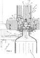
Figure 1 shows a partially sectioned perspective view of a filling device according to the present invention, prior to starting a filling operation of a receptacle and with parts removed for clarity;Figure 2 shows a larger-scale, partially sectioned front view of the filling device ofFigure 1 , with parts removed for clarity;Figure 3 shows a larger-scale, partially-sectioned front view of a main part of the filling device ofFigure 2 ;Figures 4 and5 are analogous toFigure 3 and show the main part of the filling device during the filling operation of the receptacle and at the end of such filling operation, respectively;Figure 6 is a larger-scale section along line VI-VI ofFigure 2 ;Figure 7 is a larger-scale section along line VII-VII ofFigure 2 ;Figure 8 is a larger-scale section along line VIII-VIII ofFigure 2 ; andFigure 9 is a larger-scale section along line IX-IX ofFigure 2 .Number 1 in the enclosed Figures indicates as a whole a filling device according to the present invention, which is adapted to be incorporated in a filling machine 2 (only partially shown inFigures 1 and2 ) in aseptic or ultra-clean conditions (known per se and not shown) forfilling receptacles 3, in particular made up of plastic material, with a pourable product, in particular a pourable food product, such as a still or a carbonated beverage.- Filling
machine 2 is typically fed with sterilisedempty receptacles 3 and fills the latter with the pourable product in aseptic conditions. For this purpose,filling machine 2 typically comprises a product tank (known per se and not shown) containing the pourable product, a carousel conveyor 4 (only partially shown inFigures 1 and2 ) rotating about a vertical axis and protrudingly bearing on its peripheral portion a plurality of filling devices 1 (only one shown in the enclosed Figures) for fillingrespective receptacles 3 during rotation of thecarousel conveyor 4 itself. - In the example shown in
Figures 1 to 5 , eachreceptacle 3 is defined by a bottle having a longitudinal axis A and which is advanced in a vertical position by thecarousel conveyor 4. In particular, eachreceptacle 3 is inferiorly bounded by abottom wall 5, substantially perpendicular to axis A, and has atop neck 6 coaxial with the axis A itself and defining an inlet/outlet mouth for the pourable product; theneck 6 is preferably equipped with a threadedsurface 7 designed to allow the closing off by a screw cap (known per se and not shown). - With reference to the enclosed Figures, each
filling device 1 comprises afilling valve 8, adapted to control feeding of the pourable product, and support means 10 adapted to support onerespective receptacle 3 below thefilling valve 8 and in a vertical position, in whichsuch receptacle 3 has itsneck 6 placed in contact with thefilling valve 8 to receive from the latter the pourable product. - Valve 8 basically comprises:
- a vertical
tubular body 11 fixed to the peripheral portion of thecarousel conveyor 4 and defining a central flowingchannel 12 for feeding the pourable product to therespective receptacle 3; - a
shutter 13 engaging in a sliding mannertubular body 11 and movable withinchannel 12 to allow or prevent flow of the pourable product towards therespective receptacle 3; and - actuator means 14 arranged completely externally to
tubular body 11 and magnetically coupled toshutter 13 to move the latter withinchannel 12. - In particular,
tubular body 11 has a longitudinal axis B, parallel to the rotation axis ofcarousel conveyor 4, and terminates at itsupper end 15 with anaxial inlet opening 16, for receiving the pourable product from the product tank, and at itslower end 17 with an outlet opening 18 for feeding the pourable product to therespective receptacle 3. - More specifically, axial inlet opening 16 of
upper end 15 is directly connected to aproduct conduit 19 extending from thetubular body 11 to the product tank. Lower end 17 oftubular body 11 is adapted to contact in use thetop neck 6 of thereceptacle 3 to be filled so as to put the inlet/outlet mouth of thereceptacle 3 itself in direct connection with outlet opening 18. In greater details,lower end 17 comprises anannular gasket 20 adapted to define an abutment for thetop neck 6 of therespective receptacle 3 and to sealingly close the latter during filling; in this way, the interior of thereceptacle 3 is maintained in a sealed condition during filling with the pourable product.- As clearly visible in
Figures 1 to 5 , support means 10 are configured to receive and retain arelative receptacle 3 in a suspended position with its axis A coaxial to axis B of thefilling valve 8. In particular, support means 10 comprise agripping member 21, arranged below fillingvalve 8 and configured to retain arelative receptacle 3 by theneck 6, and actuator means 22 for moving thegripping member 21, and therefore therespective receptacle 3, towards and away fromannular gasket 20 oflower end 17 oftubular body 11. - With particular reference to
Figures 3 to 5 ,channel 12 comprises, in the vicinity of outlet opening 18, a tapered-section portion 23 located at a given axial distance from, and above, the outlet opening 18 itself and tapering towards the latter up to a narrowed-section zone 23a. More specifically, tapered-section portion 23 defined by a frustum-conical inner surface oftubular body 11, which tapers from an upper cylindricalinner surface 25 of thetubular body 11 itself. Narrowed-section zone 23a represents the minimum-diameter zone of tapered-section portion 23. - With reference to
Figures 1 to 5 and9 ,shutter 13 is coaxially mounted withinchannel 12 oftubular body 11 and comprises a substantially cylindricalmain portion 27, sliding within thetubular body 11 itself, and apointed closing head 28, axially protruding frommain portion 27 and configured to cooperate in a fluid-tight manner with tapered-section portion 23 ofchannel 12. - In particular, closing
head 28 terminates with a conical surface, which is complementary to the inner frustum-conical surface oftubular body 11 defining tapered-section portion 23 and is configured to cooperate in use with such surface to sealingly close fluidic connection offilling valve 8 with therespective receptacle 3. To this aim, the conical surface of closinghead 28 is provided with anannular gasket 28a directly contacting in use the surface oftubular body 11 delimiting tapered-section portion 23 ofchannel 12. Shutter 13 is movable withinchannel 12 between a lowered closed position (Figures 1 ,2 ,3 and5 ), in which theshutter 13 sealingly closes the tapered-section portion 23 of thechannel 12 itself and interrupts flowing of the pourable product towards the outlet opening 18, and a raised open position (Figure 4 ), in which theshutter 13 delimits with the tapered-section portion 23 anannular passage 29 communicating with the outlet opening 18.- With particular reference to
Figure 2 ,main portion 27 ofshutter 13 comprises at least one permanent-magnet unit 30 magnetically coupled with at least one permanent-magnet unit 31 of actuator means 14. - More specifically, permanent-
magnet unit 30 comprises at least twopermanent magnets 30a arranged adjacent to one another with identical magnetic poles facing axially. Thepermanent magnets 30a are conveniently incorporated withinmain portion 27 ofshutter 13. - In a completely analogous way, permanent-
magnet unit 31 comprises at least twopermanent magnets 31a arranged adjacent to one another with identical magnetic poles facing axially, and oriented, with respect to thepermanent magnets 30a ofshutter 13, with different magnetic poles reciprocally facing radially. In particular, permanent-magnet unit 31 also comprises acylindrical casing 31b internally housingpermanent magnets 31a. - Actuator means 14 comprise, in a known manner, a magnetic
movable member 32, coaxially coupled in a sliding manner onto an outer surface 33 oftubular body 11 and provided with the permanent-magnet unit 31, and a driving linear actuator (know per se and not shown) for displacingmovable member 32 and, through magnetic attraction, shutter 13 along axis B. - With reference to the enclosed Figures,
tubular body 11 also defines: - an
exhaust conduit 35, which is connected, through anexhaust circuit 36 and an ON/OFF valve 37, to an annular chamber 38 (known per se and only partially shown) formed in thecarousel conveyor 4 and communicating in a known manner with the outer atmosphere in a switchable manner; - a pressurizing
conduit 40, which is connected, through apressurization circuit 41 and an ON/OFF valve 42, to an annular chamber 43 (known per se and only partially shown) formed in thecarousel conveyor 4 and filled with a pressurization fluid, such as carbon dioxide; and - a
decompression conduit 45, which is connected, through adecompression circuit 46 and an ON/OFF valve 47, to an annular discharge chamber 48 (known per se and only partially shown). - In particular,
exhaust conduit 35 is used for exhausting the gas, typically air and/or CO2, present within the interior of thereceptacle 3 during filling, when the latter is carried out in a sealed condition. Pressurizing conduit 40 is used for pressurizing thereceptacle 3 to be filled at a pressure higher than the atmospheric pressure; this conduit is typically used forreceptacles 3 to be filled with a carbonated liquid.Decompression conduit 45 is used for depressurizing the filledreceptacle 3 at the end of filling; even this conduit is typically used forreceptacles 3 filled under pressure with a carbonated liquid.Conduits tubular body 11 and are all distinct from one another.- Each one of these
conduits channel 12 and on an outer circumference thanchannel 12 with reference to axis A. More specifically and as clearly visible inFigure 9 , all theseconduits channel 12 with reference to axis B. - According to an important aspect of the present invention,
channel 12 oftubular body 11 also comprises an enlarged-section portion 50 (Figures 3 to 5 and9 ) located immediately below tapered-section portion 23, having a larger diameter than narrowed-section zone 23a with reference to axis B and defining anexpansion chamber 51 also receiving bottom end openings ofrespective conduits - In practice, all
conduits expansion chamber 51 ofchannel 12 through respective bottom end openings. - As shown in particular in
Figure 9 , allconduits channel 12 and axis B. - In the particular example shown in the enclosed Figures,
expansion chamber 51 extends from axis B up to the circumference C, on whichconduits - The diameter of enlarged-
section portion 50 ofchannel 12 is preferably constant along the entire axial height of the enlarged-section portion 50 itself. Channel 12 further comprises a reduced-section end portion 55 connecting enlarged-section portion 50 tooutlet opening 18 and having a smaller diameter than the enlarged-section portion 50 itself. In particular, the diameter of the reduced-section portion 55 ofchannel 12 decreases towards outlet opening 18.- Operation of filling
device 1 will now be described with reference to onereceptacle 3 and as of the instant in whichsuch receptacle 3 is fed to fillingmachine 2 in order to be filled with a pourable product. - In particular, the
receptacle 3 is retained at itsneck 6 by the grippingmember 21 in a vertical position, i.e. with its axis A coaxial to the axis B of the fillingvalve 8 and itsneck 6 located in an upper position than its bottom wall 5 (Figures 2 and3 ). Thereceptacle 3 may be also supported at itsbottom wall 5 by a respective lower support plate (not shown). - In this condition, shutter 13 of filling
valve 8 is set in the lowered closed position withinchannel 12 oftubular body 11 of fillingvalve 8. In an analogous manner, allvalves exhaust circuit 36,pressurization circuit 40 anddecompression circuit 46 are set in a closed condition. - In the case in which the pourable product to be delivered is a carbonated liquid, the first step to perform is to couple the
receptacle 3 to thetubular body 11 in a fluid-tight manner. This can be achieved by activating actuator means 22 so as to raise the grippingmember 21 towards the fillingvalve 8 up to bring theneck 6 of thereceptacle 3 into contact with thegasket 20 oflower end 17 oftubular body 11. - At this point, the
receptacle 3 is subjected to a pressurization step. To this end,valve 41 ofpressurization circuit 40 is opened and is maintained in that condition up to the moment in which pressure in thereceptacle 3 reaches a desired pressure value, which depends on the particular type of product to be delivered and may amount up to 6 bar; this desired pressure value corresponds to the pressure of the product in the product tank and defines the requested condition for starting the filling operation. Then, thevalve 41 is closed. - The
shutter 13 is then moved to its raised open position (Figure 4 ), in which it allows flow of the pourable product throughannular passage 29 towards thereceptacle 3. This movement is achieved by activating the linear actuator controlling magneticmovable member 32; by effect of the magnetic coupling betweenshutter 13 and magneticmovable member 32, the translating motion of this latter member determines a corresponding axial translating motion of theshutter 13 withinchannel 12 oftubular body 11. - At the same time, the
valve 37 ofexhaust circuit 36 is opened, so that the gas present in thereceptacle 3 is discharged during the filling with the pourable product. - This step ends when the product reaches the desired level in the
receptacle 3. - Thanks to the presence of the
expansion chamber 51 immediately below the narrowed-section zone 23a of thechannel 12, the gas exiting the bottle during filling can expand during the filling operation, so that turbulence and formation of vortices are attenuated; this allows to fill thereceptacle 3 at high speed with a reduced formation of foam. - At the end of the filling, the
shutter 13 is moved to its initial lowered closed position (Figure 5 ) and thevalve 37 of theexhaust circuit 36 is closed. - The next step is the decompression of the
receptacle 3, which is achieved by opening thevalve 47 and therefore connecting thereceptacle 3 itself withdecompression circuit 46. - In the case in which the pourable product delivered to the
receptacle 3 is a non-carbonated liquid, the pressurization and decompression steps are not performed. In addition, the actual filling may occur without bringing thereceptacle 3 into contact with thegasket 20 of thetubular body 11. - The advantages of filling
device 1 according to the present invention will be clear from the foregoing description. - In particular, thanks to the presence of the enlarged-
section portion 50 immediately below the tapered-section portion 23 of thechannel 12, the gas exiting the bottle during filling can expand during the filling operation, so that turbulence and formation of vortices are quite limited; this allows to fill thereceptacle 3 at high speed with a reduced formation of foam. - Moreover, the use of
distinct conduits receptacle 3 during filling thereof and for pressurizing thereceptacle 3 before filling avoids any risk that possible residues of product present in the bottom terminal part of theexhaust conduit 35 at the end of filling may fall in thenext receptacle 3 during the following pressurizing step. And even if such residues are present at the terminal part of theexhaust conduit 35, which can be caused by small quantities of foam in the gas exiting the bottle during filling, any such residues or foam fall into the enlarged-section portion 50 and not into underlying bottle. - Clearly, changes may be made to filling
device 1 as described herein without, however, departing from the scope of protection as defined in the accompanying claims.
Claims (10)
- A filling device (1) for a filling machine (2) apt to fill receptacles (3) with a pourable product; said filling device (1) comprising:- a tubular body (11) having a longitudinal axis (B), defining a central flowing channel (12) for the pourable product and terminating at a lower end (17) with an axial outlet opening (18) adapted to deliver the pourable product to a receptacle (3) to be filled, wherein said channel (12) comprises a tapered-section portion (23) located at a given axial distance from, and above, said outlet opening (18) and tapering towards the outlet opening (18) up to a narrowed-section zone (23a);- a shutter (13) movable within said channel (12) between a lowered closed position, in which the shutter (13) sealingly closes the tapered-section portion (23) of the channel (12) and interrupts flowing of the pourable product towards the outlet opening (18), and a raised open position, in which the shutter (13) delimits with the tapered-section portion (23) an annular passage (29) communicating with the outlet opening (18); and- at least one exhaust conduit (35) formed within said tubular body (11) and arranged on one side of said channel (12) and on an outer circumference (C) that is around the channel (12) and said longitudinal axis (B);wherein said channel (12) also comprises an enlarged-section portion (50) located immediately below said tapered-section portion (23), having a larger diameter than said narrowed-section zone (23a);characterized in that said enlarged-section portion (50) defines an expansion chamber (51) also receiving a bottom end opening of said exhaust conduit (35), and wherein said channel (12) further comprises a reduced-section end portion (55) connecting said enlarged-section portion (50) to said outlet opening (18) and having a smaller diameter than said enlarged-section portion (50).
- The filling device as claimed in claim 1, wherein said expansion chamber (51) extends from said longitudinal axis (B) up to at least the circumference (C) on which said exhaust conduit (35) is located.
- The filling device as claimed in claim 1 or 2, wherein the diameter of said enlarged-section portion (50) of said channel (12) is constant along the entire axial height of the enlarged-section portion (50) itself.
- The filling device as claimed in claim 1, wherein the diameter of said reduced-section portion (55) of said channel (12) decreases towards said outlet opening (18).
- The filling device as claimed in any one of the foregoing claims, further comprising at least one pressurization conduit (40) for pressurizing the receptacle (3) to be filled at a pressure higher than the atmospheric pressure; said pressurization conduit (40) being formed within said tubular body (11), being distinct from said exhaust conduit (35) and being arranged on one side of said channel (12) as well as on an outer circumference (C) that is around the channel (12) and said longitudinal axis (B); said enlarged-section portion (50) also receiving a bottom end opening of said pressurization conduit (40).
- The filling device as claimed in claim 5, wherein both said exhaust and pressurization conduits (35, 40) are arranged on the same circumference (C) around said channel (12) and said longitudinal axis (B).
- The filling device as claimed in claim 5 or 6, further comprising at least one decompression conduit (45) for depressurizing the filled receptacle (3) at the end of filling; said decompression conduit (45) being formed within said tubular body (11), being distinct from said exhaust conduit (35) and said pressurization conduit (40) and being arranged on one side of said channel (12) as well as on an outer circumference (C) that is around the channel (12) and said longitudinal axis (B); said enlarged-section portion (50) also receiving a bottom end opening of said decompression conduit (45).
- The filling device as claimed in claim 7, wherein said exhaust, pressurization and decompression conduits (35, 40, 45) are arranged on the same circumference (C) around said channel (12) and said longitudinal axis (B).
- The filling device as claimed in any one of the foregoing claims, further comprising support means (10) configured to receive and retain said receptacle (3) as well as to move it towards and away from said lower end (17) of said tubular body (11).
- The filling device as claimed in any one of the foregoing claims, further comprising first magnetic means (30), carried by said shutter (13), and second magnetic means (31) arranged externally of said tubular body (11), magnetically coupled to said first magnetic means (30), and selectively activated to move the first magnetic means (30) and the shutter (13) by magnetic attraction along said longitudinal axis (B) between said raised open position and said lowered closed position.
Priority Applications (4)
| Application Number | Priority Date | Filing Date | Title |
|---|---|---|---|
| EP15306936.4AEP3176126B1 (en) | 2015-12-04 | 2015-12-04 | A filling device for a filling machine |
| JP2016199729AJP2017100805A (en) | 2015-12-04 | 2016-10-11 | Filling device for filling machine |
| CN201610946940.9ACN106829836B (en) | 2015-12-04 | 2016-10-26 | Filling device for filling machine |
| US15/367,779US10370234B2 (en) | 2015-12-04 | 2016-12-02 | Filling device for filling machine |
Applications Claiming Priority (1)
| Application Number | Priority Date | Filing Date | Title |
|---|---|---|---|
| EP15306936.4AEP3176126B1 (en) | 2015-12-04 | 2015-12-04 | A filling device for a filling machine |
Publications (2)
| Publication Number | Publication Date |
|---|---|
| EP3176126A1 EP3176126A1 (en) | 2017-06-07 |
| EP3176126B1true EP3176126B1 (en) | 2018-08-08 |
Family
ID=54838296
Family Applications (1)
| Application Number | Title | Priority Date | Filing Date |
|---|---|---|---|
| EP15306936.4ANot-in-forceEP3176126B1 (en) | 2015-12-04 | 2015-12-04 | A filling device for a filling machine |
Country Status (4)
| Country | Link |
|---|---|
| US (1) | US10370234B2 (en) |
| EP (1) | EP3176126B1 (en) |
| JP (1) | JP2017100805A (en) |
| CN (1) | CN106829836B (en) |
Families Citing this family (11)
| Publication number | Priority date | Publication date | Assignee | Title |
|---|---|---|---|---|
| USD846608S1 (en)* | 2017-03-14 | 2019-04-23 | M&M Machinery Services, Inc. | Receiver for a bottling machine |
| EP3421411B1 (en)* | 2017-06-30 | 2021-11-10 | Sidel Participations | Filling unit for filling an article with a pourable product |
| AR113617A1 (en)* | 2017-12-08 | 2020-05-20 | Johnson & Son Inc S C | PRESSURIZED DISPENSING ARRANGEMENT INCLUDING A PLASTIC BOTTLE AND PROCESS TO MINIMIZE THE FORMATION OF STRESS CRACKING IN A PLASTIC BOTTLE |
| IT201800007011A1 (en)* | 2018-07-06 | 2020-01-06 | DEVICE FOR TIGHTNESS TEST IN A VACUUM CHAMBER AND PROCEDURE FOR CARRYING OUT THIS TEST | |
| DE102018219119A1 (en)* | 2018-11-09 | 2020-05-14 | Krones Ag | Process for back pressure filling of containers and filling system of a back pressure filler |
| IT201800011110A1 (en)* | 2018-12-14 | 2020-06-14 | Lanfranchi Srl | APPARATUS FOR FILLING CONTAINERS WITH A CORRESPONDING PRODUCT |
| US11208310B2 (en)* | 2019-05-06 | 2021-12-28 | Fountain Master, Llc | Fluid filling systems and methods |
| JP7457235B2 (en)* | 2020-02-18 | 2024-03-28 | 澁谷工業株式会社 | filling equipment |
| CN111977594A (en)* | 2020-07-27 | 2020-11-24 | 江苏新美星包装机械股份有限公司 | Non-contact isobaric filling valve |
| CN111847360B (en)* | 2020-08-14 | 2021-11-26 | 江西艾丽斯日化有限公司 | Filling head with anti-dripping function for filling paste cosmetics |
| DE102020131817A1 (en)* | 2020-12-01 | 2022-06-02 | Krones Aktiengesellschaft | Device and method for filling a container with a filling product |
Family Cites Families (27)
| Publication number | Priority date | Publication date | Assignee | Title |
|---|---|---|---|---|
| US1166607A (en)* | 1911-03-29 | 1916-01-04 | Crown Cork & Seal Company Of Baltimore City | Bottle-filling mechanism. |
| US3047032A (en)* | 1959-04-13 | 1962-07-31 | Meyer Geo J Mfg Co | Container filling apparatus |
| US3411745A (en)* | 1966-04-11 | 1968-11-19 | Haskon Inc | Fill valve assembly |
| DE1607996A1 (en)* | 1967-07-22 | 1972-03-02 | Seitz Werke Gmbh | Filling element for counter pressure filling machine |
| US3870089A (en) | 1972-06-12 | 1975-03-11 | Iii Herman Laub | Antidrip volumetric rapid filling machine |
| IT1226494B (en) | 1984-10-02 | 1991-01-16 | Simonazzi Spa A & L | CONTINUOUS FILLING MACHINE WITH FIXED HEIGHT ROTARY BENCH EQUIPPED WITH AUXILIARY PNEUMATIC JACKS TO OPTIMIZE THE LIP SEALING CONDITIONS OF THE MOUTH OF CONTAINERS VERY DELICATE ACCORDING TO THE EVOLVING OF FILLING PROCESSES |
| DE3809852A1 (en)* | 1988-03-24 | 1989-10-05 | Seitz Enzinger Noll Masch | METHOD FOR ASEPTIC OR STERILE FILLING OF LIQUID FILLING MATERIAL IN CONTAINERS AND DEVICE FOR CARRYING OUT THIS PROCESS |
| DE4309429A1 (en) | 1993-03-24 | 1994-09-29 | Khs Masch & Anlagenbau Ag | Filling machine |
| DE9311427U1 (en)* | 1993-07-31 | 1994-09-08 | Krones Ag Hermann Kronseder Maschinenfabrik, 93073 Neutraubling | Device for filling vessels with a liquid |
| JP2856057B2 (en) | 1993-12-28 | 1999-02-10 | 東洋製罐株式会社 | Method and apparatus for filling carbonated beverages |
| DE4429594A1 (en)* | 1994-08-20 | 1996-02-22 | Khs Masch & Anlagenbau Ag | Process for filling a liquid product into bottles or the like |
| US5924462A (en)* | 1997-09-03 | 1999-07-20 | Crown Simplimatic | Beverage filling machine |
| DE19818762A1 (en)* | 1998-04-27 | 1999-10-28 | Khs Masch & Anlagenbau Ag | Filling system and filling element |
| IT1316665B1 (en)* | 2000-02-24 | 2003-04-24 | Ocme Srl | FILLING NOZZLE WITH INTERCEPTION OF LIQUIDS IN FEED FOR FILLING MACHINES |
| DE10028676A1 (en)* | 2000-06-09 | 2002-06-20 | Khs Masch & Anlagenbau Ag | Process for filling bottles, cans or similar containers with a liquid filling material and filling machine |
| FR2838730B1 (en)* | 2002-04-22 | 2004-06-18 | Serac Group | ELECTROMAGNETICALLY CONTROLLED FILLING NOZZLE |
| JP4411832B2 (en) | 2002-10-17 | 2010-02-10 | 澁谷工業株式会社 | Filling valve |
| ITBO20030411A1 (en)* | 2003-07-03 | 2005-01-04 | Stk Stocchi Progetti S R L | TAP FOR STERILE FILLING OF FOOD LIQUIDS. |
| WO2005019090A1 (en) | 2003-08-16 | 2005-03-03 | Krones Ag | Counter-pressure filling device and method for counter-pressure filling |
| JP4254568B2 (en)* | 2004-02-16 | 2009-04-15 | 澁谷工業株式会社 | Filling valve |
| JP2007290743A (en)* | 2006-04-25 | 2007-11-08 | Shibuya Kogyo Co Ltd | Filling valve |
| JP2008105699A (en)* | 2006-10-25 | 2008-05-08 | Shibuya Kogyo Co Ltd | Filling valve |
| EP2086868B1 (en)* | 2006-11-29 | 2012-02-08 | Sidel International AG | Filler valve unit |
| US20100037983A1 (en)* | 2008-08-12 | 2010-02-18 | The Coca-Cola Company | Neck ring seal |
| ITTO20110936A1 (en)* | 2011-10-18 | 2013-04-19 | Sidel Spa Con Socio Unico | DOSING BODY FOR FILLING MACHINE |
| EP2749501B1 (en)* | 2012-12-28 | 2017-08-02 | Sidel S.p.a. Con Socio Unico | A machine and a method for filling and labelling containers |
| EP2871150B1 (en)* | 2013-11-08 | 2017-02-01 | Sidel S.p.a. Con Socio Unico | Filling unit and method for filling an article with a pourable product |
- 2015
- 2015-12-04EPEP15306936.4Apatent/EP3176126B1/ennot_activeNot-in-force
- 2016
- 2016-10-11JPJP2016199729Apatent/JP2017100805A/enactivePending
- 2016-10-26CNCN201610946940.9Apatent/CN106829836B/ennot_activeExpired - Fee Related
- 2016-12-02USUS15/367,779patent/US10370234B2/ennot_activeExpired - Fee Related
Non-Patent Citations (1)
| Title |
|---|
| None* |
Also Published As
| Publication number | Publication date |
|---|---|
| CN106829836A (en) | 2017-06-13 |
| US10370234B2 (en) | 2019-08-06 |
| US20170158480A1 (en) | 2017-06-08 |
| CN106829836B (en) | 2021-04-13 |
| EP3176126A1 (en) | 2017-06-07 |
| JP2017100805A (en) | 2017-06-08 |
Similar Documents
| Publication | Publication Date | Title |
|---|---|---|
| EP3176126B1 (en) | A filling device for a filling machine | |
| US7469726B2 (en) | Beverage bottling plant for filling bottles with a liquid beverage, having a filling machine with a rotary construction for filling bottles with a liquid beverage | |
| JP4688532B2 (en) | Filling element and filling machine having a filling element of this type | |
| US9233826B2 (en) | Magnetically actuated flow-rate selector | |
| US11655132B2 (en) | Apparatus for filling a container with a filling product | |
| US20080271812A1 (en) | Rotary filling machine for filling containers with liquids | |
| US20110197996A1 (en) | Filling element for filling bottles or like containers and filling machine comprising such filling elements | |
| EP3473590B1 (en) | Improved filling device for a filling machine | |
| US10302214B2 (en) | Flow control valve for filling machine | |
| CN110577177B (en) | Filling valve for filling containers and filling machine | |
| CN208979227U (en) | Processing equipment for process container and the machine for production and processing container | |
| US20150266711A1 (en) | Filling unit for filling containers with pourable products | |
| EP3543205B1 (en) | Filling valve, filling machine and method for filling receptacles | |
| WO2018091291A1 (en) | A filling machine for filling receptacles with a pourable product | |
| EP3357859A1 (en) | Filling valve, filling apparatus having such a filling valve and method of operating such a filling valve | |
| EP3473588A1 (en) | Device and method for filling receptacles with a pourable product under pressure | |
| CN113003519A (en) | Device and method for filling containers with a filling product | |
| EP2889261B1 (en) | Device for filling a receptacle and filling machine | |
| EP3659963B1 (en) | Filling plant and method for filling receptacles with a pourable food product | |
| EP2480489B1 (en) | Tank-replenishing device assembly | |
| EP3473589A1 (en) | Filling machine and method for filling receptacles with a pourable product under pressure |
Legal Events
| Date | Code | Title | Description |
|---|---|---|---|
| AK | Designated contracting states | Kind code of ref document:A1 Designated state(s):AL AT BE BG CH CY CZ DE DK EE ES FI FR GB GR HR HU IE IS IT LI LT LU LV MC MK MT NL NO PL PT RO RS SE SI SK SM TR | |
| AX | Request for extension of the european patent | Extension state:BA ME | |
| PUAI | Public reference made under article 153(3) epc to a published international application that has entered the european phase | Free format text:ORIGINAL CODE: 0009012 | |
| 17P | Request for examination filed | Effective date:20171116 | |
| RBV | Designated contracting states (corrected) | Designated state(s):AL AT BE BG CH CY CZ DE DK EE ES FI FR GB GR HR HU IE IS IT LI LT LU LV MC MK MT NL NO PL PT RO RS SE SI SK SM TR | |
| GRAP | Despatch of communication of intention to grant a patent | Free format text:ORIGINAL CODE: EPIDOSNIGR1 | |
| RIC1 | Information provided on ipc code assigned before grant | Ipc:B67C 3/28 20060101AFI20180320BHEP | |
| INTG | Intention to grant announced | Effective date:20180406 | |
| GRAJ | Information related to disapproval of communication of intention to grant by the applicant or resumption of examination proceedings by the epo deleted | Free format text:ORIGINAL CODE: EPIDOSDIGR1 | |
| GRAP | Despatch of communication of intention to grant a patent | Free format text:ORIGINAL CODE: EPIDOSNIGR1 | |
| GRAS | Grant fee paid | Free format text:ORIGINAL CODE: EPIDOSNIGR3 | |
| GRAA | (expected) grant | Free format text:ORIGINAL CODE: 0009210 | |
| INTC | Intention to grant announced (deleted) | ||
| INTG | Intention to grant announced | Effective date:20180620 | |
| AK | Designated contracting states | Kind code of ref document:B1 Designated state(s):AL AT BE BG CH CY CZ DE DK EE ES FI FR GB GR HR HU IE IS IT LI LT LU LV MC MK MT NL NO PL PT RO RS SE SI SK SM TR | |
| REG | Reference to a national code | Ref country code:GB Ref legal event code:FG4D | |
| REG | Reference to a national code | Ref country code:CH Ref legal event code:EP Ref country code:AT Ref legal event code:REF Ref document number:1026732 Country of ref document:AT Kind code of ref document:T Effective date:20180815 | |
| REG | Reference to a national code | Ref country code:IE Ref legal event code:FG4D | |
| REG | Reference to a national code | Ref country code:DE Ref legal event code:R096 Ref document number:602015014602 Country of ref document:DE | |
| REG | Reference to a national code | Ref country code:NL Ref legal event code:MP Effective date:20180808 | |
| REG | Reference to a national code | Ref country code:LT Ref legal event code:MG4D | |
| REG | Reference to a national code | Ref country code:AT Ref legal event code:MK05 Ref document number:1026732 Country of ref document:AT Kind code of ref document:T Effective date:20180808 | |
| PG25 | Lapsed in a contracting state [announced via postgrant information from national office to epo] | Ref country code:FI Free format text:LAPSE BECAUSE OF FAILURE TO SUBMIT A TRANSLATION OF THE DESCRIPTION OR TO PAY THE FEE WITHIN THE PRESCRIBED TIME-LIMIT Effective date:20180808 Ref country code:LT Free format text:LAPSE BECAUSE OF FAILURE TO SUBMIT A TRANSLATION OF THE DESCRIPTION OR TO PAY THE FEE WITHIN THE PRESCRIBED TIME-LIMIT Effective date:20180808 Ref country code:PL Free format text:LAPSE BECAUSE OF FAILURE TO SUBMIT A TRANSLATION OF THE DESCRIPTION OR TO PAY THE FEE WITHIN THE PRESCRIBED TIME-LIMIT Effective date:20180808 Ref country code:GR Free format text:LAPSE BECAUSE OF FAILURE TO SUBMIT A TRANSLATION OF THE DESCRIPTION OR TO PAY THE FEE WITHIN THE PRESCRIBED TIME-LIMIT Effective date:20181109 Ref country code:NO Free format text:LAPSE BECAUSE OF FAILURE TO SUBMIT A TRANSLATION OF THE DESCRIPTION OR TO PAY THE FEE WITHIN THE PRESCRIBED TIME-LIMIT Effective date:20181108 Ref country code:AT Free format text:LAPSE BECAUSE OF FAILURE TO SUBMIT A TRANSLATION OF THE DESCRIPTION OR TO PAY THE FEE WITHIN THE PRESCRIBED TIME-LIMIT Effective date:20180808 Ref country code:NL Free format text:LAPSE BECAUSE OF FAILURE TO SUBMIT A TRANSLATION OF THE DESCRIPTION OR TO PAY THE FEE WITHIN THE PRESCRIBED TIME-LIMIT Effective date:20180808 Ref country code:BG Free format text:LAPSE BECAUSE OF FAILURE TO SUBMIT A TRANSLATION OF THE DESCRIPTION OR TO PAY THE FEE WITHIN THE PRESCRIBED TIME-LIMIT Effective date:20181108 Ref country code:SE Free format text:LAPSE BECAUSE OF FAILURE TO SUBMIT A TRANSLATION OF THE DESCRIPTION OR TO PAY THE FEE WITHIN THE PRESCRIBED TIME-LIMIT Effective date:20180808 Ref country code:IS Free format text:LAPSE BECAUSE OF FAILURE TO SUBMIT A TRANSLATION OF THE DESCRIPTION OR TO PAY THE FEE WITHIN THE PRESCRIBED TIME-LIMIT Effective date:20181208 Ref country code:RS Free format text:LAPSE BECAUSE OF FAILURE TO SUBMIT A TRANSLATION OF THE DESCRIPTION OR TO PAY THE FEE WITHIN THE PRESCRIBED TIME-LIMIT Effective date:20180808 | |
| PG25 | Lapsed in a contracting state [announced via postgrant information from national office to epo] | Ref country code:HR Free format text:LAPSE BECAUSE OF FAILURE TO SUBMIT A TRANSLATION OF THE DESCRIPTION OR TO PAY THE FEE WITHIN THE PRESCRIBED TIME-LIMIT Effective date:20180808 Ref country code:LV Free format text:LAPSE BECAUSE OF FAILURE TO SUBMIT A TRANSLATION OF THE DESCRIPTION OR TO PAY THE FEE WITHIN THE PRESCRIBED TIME-LIMIT Effective date:20180808 Ref country code:AL Free format text:LAPSE BECAUSE OF FAILURE TO SUBMIT A TRANSLATION OF THE DESCRIPTION OR TO PAY THE FEE WITHIN THE PRESCRIBED TIME-LIMIT Effective date:20180808 | |
| PG25 | Lapsed in a contracting state [announced via postgrant information from national office to epo] | Ref country code:ES Free format text:LAPSE BECAUSE OF FAILURE TO SUBMIT A TRANSLATION OF THE DESCRIPTION OR TO PAY THE FEE WITHIN THE PRESCRIBED TIME-LIMIT Effective date:20180808 Ref country code:EE Free format text:LAPSE BECAUSE OF FAILURE TO SUBMIT A TRANSLATION OF THE DESCRIPTION OR TO PAY THE FEE WITHIN THE PRESCRIBED TIME-LIMIT Effective date:20180808 Ref country code:RO Free format text:LAPSE BECAUSE OF FAILURE TO SUBMIT A TRANSLATION OF THE DESCRIPTION OR TO PAY THE FEE WITHIN THE PRESCRIBED TIME-LIMIT Effective date:20180808 Ref country code:CZ Free format text:LAPSE BECAUSE OF FAILURE TO SUBMIT A TRANSLATION OF THE DESCRIPTION OR TO PAY THE FEE WITHIN THE PRESCRIBED TIME-LIMIT Effective date:20180808 | |
| REG | Reference to a national code | Ref country code:DE Ref legal event code:R097 Ref document number:602015014602 Country of ref document:DE | |
| PG25 | Lapsed in a contracting state [announced via postgrant information from national office to epo] | Ref country code:DK Free format text:LAPSE BECAUSE OF FAILURE TO SUBMIT A TRANSLATION OF THE DESCRIPTION OR TO PAY THE FEE WITHIN THE PRESCRIBED TIME-LIMIT Effective date:20180808 Ref country code:SK Free format text:LAPSE BECAUSE OF FAILURE TO SUBMIT A TRANSLATION OF THE DESCRIPTION OR TO PAY THE FEE WITHIN THE PRESCRIBED TIME-LIMIT Effective date:20180808 Ref country code:SM Free format text:LAPSE BECAUSE OF FAILURE TO SUBMIT A TRANSLATION OF THE DESCRIPTION OR TO PAY THE FEE WITHIN THE PRESCRIBED TIME-LIMIT Effective date:20180808 | |
| PLBE | No opposition filed within time limit | Free format text:ORIGINAL CODE: 0009261 | |
| STAA | Information on the status of an ep patent application or granted ep patent | Free format text:STATUS: NO OPPOSITION FILED WITHIN TIME LIMIT | |
| 26N | No opposition filed | Effective date:20190509 | |
| REG | Reference to a national code | Ref country code:CH Ref legal event code:PL | |
| PG25 | Lapsed in a contracting state [announced via postgrant information from national office to epo] | Ref country code:LU Free format text:LAPSE BECAUSE OF NON-PAYMENT OF DUE FEES Effective date:20181204 Ref country code:MC Free format text:LAPSE BECAUSE OF FAILURE TO SUBMIT A TRANSLATION OF THE DESCRIPTION OR TO PAY THE FEE WITHIN THE PRESCRIBED TIME-LIMIT Effective date:20180808 Ref country code:SI Free format text:LAPSE BECAUSE OF FAILURE TO SUBMIT A TRANSLATION OF THE DESCRIPTION OR TO PAY THE FEE WITHIN THE PRESCRIBED TIME-LIMIT Effective date:20180808 | |
| REG | Reference to a national code | Ref country code:IE Ref legal event code:MM4A | |
| REG | Reference to a national code | Ref country code:BE Ref legal event code:MM Effective date:20181231 | |
| PG25 | Lapsed in a contracting state [announced via postgrant information from national office to epo] | Ref country code:IE Free format text:LAPSE BECAUSE OF NON-PAYMENT OF DUE FEES Effective date:20181204 | |
| PG25 | Lapsed in a contracting state [announced via postgrant information from national office to epo] | Ref country code:BE Free format text:LAPSE BECAUSE OF NON-PAYMENT OF DUE FEES Effective date:20181231 | |
| PG25 | Lapsed in a contracting state [announced via postgrant information from national office to epo] | Ref country code:CH Free format text:LAPSE BECAUSE OF NON-PAYMENT OF DUE FEES Effective date:20181231 Ref country code:LI Free format text:LAPSE BECAUSE OF NON-PAYMENT OF DUE FEES Effective date:20181231 | |
| PG25 | Lapsed in a contracting state [announced via postgrant information from national office to epo] | Ref country code:MT Free format text:LAPSE BECAUSE OF NON-PAYMENT OF DUE FEES Effective date:20181204 | |
| PG25 | Lapsed in a contracting state [announced via postgrant information from national office to epo] | Ref country code:TR Free format text:LAPSE BECAUSE OF FAILURE TO SUBMIT A TRANSLATION OF THE DESCRIPTION OR TO PAY THE FEE WITHIN THE PRESCRIBED TIME-LIMIT Effective date:20180808 | |
| PG25 | Lapsed in a contracting state [announced via postgrant information from national office to epo] | Ref country code:PT Free format text:LAPSE BECAUSE OF FAILURE TO SUBMIT A TRANSLATION OF THE DESCRIPTION OR TO PAY THE FEE WITHIN THE PRESCRIBED TIME-LIMIT Effective date:20180808 | |
| PG25 | Lapsed in a contracting state [announced via postgrant information from national office to epo] | Ref country code:HU Free format text:LAPSE BECAUSE OF FAILURE TO SUBMIT A TRANSLATION OF THE DESCRIPTION OR TO PAY THE FEE WITHIN THE PRESCRIBED TIME-LIMIT; INVALID AB INITIO Effective date:20151204 Ref country code:MK Free format text:LAPSE BECAUSE OF NON-PAYMENT OF DUE FEES Effective date:20180808 Ref country code:CY Free format text:LAPSE BECAUSE OF FAILURE TO SUBMIT A TRANSLATION OF THE DESCRIPTION OR TO PAY THE FEE WITHIN THE PRESCRIBED TIME-LIMIT Effective date:20180808 | |
| GBPC | Gb: european patent ceased through non-payment of renewal fee | Effective date:20191204 | |
| PG25 | Lapsed in a contracting state [announced via postgrant information from national office to epo] | Ref country code:GB Free format text:LAPSE BECAUSE OF NON-PAYMENT OF DUE FEES Effective date:20191204 | |
| PGFP | Annual fee paid to national office [announced via postgrant information from national office to epo] | Ref country code:DE Payment date:20201119 Year of fee payment:6 Ref country code:IT Payment date:20201123 Year of fee payment:6 Ref country code:FR Payment date:20201120 Year of fee payment:6 | |
| REG | Reference to a national code | Ref country code:DE Ref legal event code:R119 Ref document number:602015014602 Country of ref document:DE | |
| PG25 | Lapsed in a contracting state [announced via postgrant information from national office to epo] | Ref country code:DE Free format text:LAPSE BECAUSE OF NON-PAYMENT OF DUE FEES Effective date:20220701 | |
| PG25 | Lapsed in a contracting state [announced via postgrant information from national office to epo] | Ref country code:FR Free format text:LAPSE BECAUSE OF NON-PAYMENT OF DUE FEES Effective date:20211231 | |
| PG25 | Lapsed in a contracting state [announced via postgrant information from national office to epo] | Ref country code:IT Free format text:LAPSE BECAUSE OF NON-PAYMENT OF DUE FEES Effective date:20211204 |