EP3173107A1 - Attachment device - Google Patents
Attachment deviceDownload PDFInfo
- Publication number
- EP3173107A1 EP3173107A1EP15196333.7AEP15196333AEP3173107A1EP 3173107 A1EP3173107 A1EP 3173107A1EP 15196333 AEP15196333 AEP 15196333AEP 3173107 A1EP3173107 A1EP 3173107A1
- Authority
- EP
- European Patent Office
- Prior art keywords
- closure element
- elements
- sewing ring
- connecting device
- sealing element
- Prior art date
- Legal status (The legal status is an assumption and is not a legal conclusion. Google has not performed a legal analysis and makes no representation as to the accuracy of the status listed.)
- Withdrawn
Links
- 238000007789sealingMethods0.000claimsabstractdescription79
- 238000009958sewingMethods0.000claimsabstractdescription76
- 210000004204blood vesselAnatomy0.000claimsabstractdescription6
- 229910052751metalInorganic materials0.000claimsdescription15
- 239000002184metalSubstances0.000claimsdescription15
- 239000004744fabricSubstances0.000claimsdescription10
- 239000004753textileSubstances0.000claimsdescription9
- 239000006260foamSubstances0.000claimsdescription6
- RTAQQCXQSZGOHL-UHFFFAOYSA-NTitaniumChemical compound[Ti]RTAQQCXQSZGOHL-UHFFFAOYSA-N0.000claimsdescription5
- 239000007788liquidSubstances0.000claimsdescription5
- 239000006262metallic foamSubstances0.000claimsdescription5
- 239000011148porous materialSubstances0.000claimsdescription5
- 230000007480spreadingEffects0.000claimsdescription5
- 238000003892spreadingMethods0.000claimsdescription5
- 239000010936titaniumSubstances0.000claimsdescription5
- 229910052719titaniumInorganic materials0.000claimsdescription5
- 239000004033plasticSubstances0.000claimsdescription3
- 229920001971elastomerPolymers0.000description12
- 239000000806elastomerSubstances0.000description8
- 239000000463materialSubstances0.000description8
- 230000006835compressionEffects0.000description7
- 238000007906compressionMethods0.000description7
- 230000007246mechanismEffects0.000description6
- 238000000034methodMethods0.000description4
- 239000007787solidSubstances0.000description4
- 239000000126substanceSubstances0.000description4
- 230000001070adhesive effectEffects0.000description3
- 239000000243solutionSubstances0.000description3
- 239000000853adhesiveSubstances0.000description2
- 230000006378damageEffects0.000description2
- 230000000694effectsEffects0.000description2
- 230000012010growthEffects0.000description2
- 230000002093peripheral effectEffects0.000description2
- 238000003825pressingMethods0.000description2
- 230000008569processEffects0.000description2
- 229920002379silicone rubberPolymers0.000description2
- 241000270923Hesperostipa comataSpecies0.000description1
- 238000004026adhesive bondingMethods0.000description1
- 230000008901benefitEffects0.000description1
- 239000000560biocompatible materialSubstances0.000description1
- 230000015572biosynthetic processEffects0.000description1
- 230000010261cell growthEffects0.000description1
- 230000008859changeEffects0.000description1
- 238000004132cross linkingMethods0.000description1
- 230000001419dependent effectEffects0.000description1
- 238000005516engineering processMethods0.000description1
- 230000007613environmental effectEffects0.000description1
- 230000002349favourable effectEffects0.000description1
- 230000009969flowable effectEffects0.000description1
- 239000012530fluidSubstances0.000description1
- 238000002513implantationMethods0.000description1
- 238000002347injectionMethods0.000description1
- 239000007924injectionSubstances0.000description1
- 230000007774longtermEffects0.000description1
- 238000011089mechanical engineeringMethods0.000description1
- 230000001737promoting effectEffects0.000description1
- 238000007669thermal treatmentMethods0.000description1
- 230000008719thickeningEffects0.000description1
- 238000003466weldingMethods0.000description1
Images


Classifications
- A—HUMAN NECESSITIES
- A61—MEDICAL OR VETERINARY SCIENCE; HYGIENE
- A61M—DEVICES FOR INTRODUCING MEDIA INTO, OR ONTO, THE BODY; DEVICES FOR TRANSDUCING BODY MEDIA OR FOR TAKING MEDIA FROM THE BODY; DEVICES FOR PRODUCING OR ENDING SLEEP OR STUPOR
- A61M60/00—Blood pumps; Devices for mechanical circulatory actuation; Balloon pumps for circulatory assistance
- A61M60/80—Constructional details other than related to driving
- A61M60/855—Constructional details other than related to driving of implantable pumps or pumping devices
- A61M60/861—Connections or anchorings for connecting or anchoring pumps or pumping devices to parts of the patient's body
- A61M60/863—Apex rings
- A—HUMAN NECESSITIES
- A61—MEDICAL OR VETERINARY SCIENCE; HYGIENE
- A61M—DEVICES FOR INTRODUCING MEDIA INTO, OR ONTO, THE BODY; DEVICES FOR TRANSDUCING BODY MEDIA OR FOR TAKING MEDIA FROM THE BODY; DEVICES FOR PRODUCING OR ENDING SLEEP OR STUPOR
- A61M60/00—Blood pumps; Devices for mechanical circulatory actuation; Balloon pumps for circulatory assistance
- A61M60/10—Location thereof with respect to the patient's body
- A61M60/122—Implantable pumps or pumping devices, i.e. the blood being pumped inside the patient's body
- A61M60/126—Implantable pumps or pumping devices, i.e. the blood being pumped inside the patient's body implantable via, into, inside, in line, branching on, or around a blood vessel
- A61M60/148—Implantable pumps or pumping devices, i.e. the blood being pumped inside the patient's body implantable via, into, inside, in line, branching on, or around a blood vessel in line with a blood vessel using resection or like techniques, e.g. permanent endovascular heart assist devices
- A—HUMAN NECESSITIES
- A61—MEDICAL OR VETERINARY SCIENCE; HYGIENE
- A61B—DIAGNOSIS; SURGERY; IDENTIFICATION
- A61B17/00—Surgical instruments, devices or methods
- A61B17/12—Surgical instruments, devices or methods for ligaturing or otherwise compressing tubular parts of the body, e.g. blood vessels or umbilical cord
- A61B17/12022—Occluding by internal devices, e.g. balloons or releasable wires
- A61B17/12131—Occluding by internal devices, e.g. balloons or releasable wires characterised by the type of occluding device
- A61B17/12136—Balloons
- A—HUMAN NECESSITIES
- A61—MEDICAL OR VETERINARY SCIENCE; HYGIENE
- A61F—FILTERS IMPLANTABLE INTO BLOOD VESSELS; PROSTHESES; DEVICES PROVIDING PATENCY TO, OR PREVENTING COLLAPSING OF, TUBULAR STRUCTURES OF THE BODY, e.g. STENTS; ORTHOPAEDIC, NURSING OR CONTRACEPTIVE DEVICES; FOMENTATION; TREATMENT OR PROTECTION OF EYES OR EARS; BANDAGES, DRESSINGS OR ABSORBENT PADS; FIRST-AID KITS
- A61F2/00—Filters implantable into blood vessels; Prostheses, i.e. artificial substitutes or replacements for parts of the body; Appliances for connecting them with the body; Devices providing patency to, or preventing collapsing of, tubular structures of the body, e.g. stents
- A61F2/02—Prostheses implantable into the body
- A61F2/24—Heart valves ; Vascular valves, e.g. venous valves; Heart implants, e.g. passive devices for improving the function of the native valve or the heart muscle; Transmyocardial revascularisation [TMR] devices; Valves implantable in the body
- A61F2/2409—Support rings therefor, e.g. for connecting valves to tissue
- A—HUMAN NECESSITIES
- A61—MEDICAL OR VETERINARY SCIENCE; HYGIENE
- A61M—DEVICES FOR INTRODUCING MEDIA INTO, OR ONTO, THE BODY; DEVICES FOR TRANSDUCING BODY MEDIA OR FOR TAKING MEDIA FROM THE BODY; DEVICES FOR PRODUCING OR ENDING SLEEP OR STUPOR
- A61M39/00—Tubes, tube connectors, tube couplings, valves, access sites or the like, specially adapted for medical use
- A61M39/10—Tube connectors; Tube couplings
- A61M39/1011—Locking means for securing connection; Additional tamper safeties
- A—HUMAN NECESSITIES
- A61—MEDICAL OR VETERINARY SCIENCE; HYGIENE
- A61M—DEVICES FOR INTRODUCING MEDIA INTO, OR ONTO, THE BODY; DEVICES FOR TRANSDUCING BODY MEDIA OR FOR TAKING MEDIA FROM THE BODY; DEVICES FOR PRODUCING OR ENDING SLEEP OR STUPOR
- A61M39/00—Tubes, tube connectors, tube couplings, valves, access sites or the like, specially adapted for medical use
- A61M39/10—Tube connectors; Tube couplings
- A61M39/12—Tube connectors; Tube couplings for joining a flexible tube to a rigid attachment
- A—HUMAN NECESSITIES
- A61—MEDICAL OR VETERINARY SCIENCE; HYGIENE
- A61M—DEVICES FOR INTRODUCING MEDIA INTO, OR ONTO, THE BODY; DEVICES FOR TRANSDUCING BODY MEDIA OR FOR TAKING MEDIA FROM THE BODY; DEVICES FOR PRODUCING OR ENDING SLEEP OR STUPOR
- A61M60/00—Blood pumps; Devices for mechanical circulatory actuation; Balloon pumps for circulatory assistance
- A61M60/10—Location thereof with respect to the patient's body
- A61M60/122—Implantable pumps or pumping devices, i.e. the blood being pumped inside the patient's body
- A61M60/165—Implantable pumps or pumping devices, i.e. the blood being pumped inside the patient's body implantable in, on, or around the heart
- A61M60/178—Implantable pumps or pumping devices, i.e. the blood being pumped inside the patient's body implantable in, on, or around the heart drawing blood from a ventricle and returning the blood to the arterial system via a cannula external to the ventricle, e.g. left or right ventricular assist devices
- A—HUMAN NECESSITIES
- A61—MEDICAL OR VETERINARY SCIENCE; HYGIENE
- A61M—DEVICES FOR INTRODUCING MEDIA INTO, OR ONTO, THE BODY; DEVICES FOR TRANSDUCING BODY MEDIA OR FOR TAKING MEDIA FROM THE BODY; DEVICES FOR PRODUCING OR ENDING SLEEP OR STUPOR
- A61M60/00—Blood pumps; Devices for mechanical circulatory actuation; Balloon pumps for circulatory assistance
- A61M60/20—Type thereof
- A61M60/205—Non-positive displacement blood pumps
- A61M60/216—Non-positive displacement blood pumps including a rotating member acting on the blood, e.g. impeller
- A—HUMAN NECESSITIES
- A61—MEDICAL OR VETERINARY SCIENCE; HYGIENE
- A61M—DEVICES FOR INTRODUCING MEDIA INTO, OR ONTO, THE BODY; DEVICES FOR TRANSDUCING BODY MEDIA OR FOR TAKING MEDIA FROM THE BODY; DEVICES FOR PRODUCING OR ENDING SLEEP OR STUPOR
- A61M60/00—Blood pumps; Devices for mechanical circulatory actuation; Balloon pumps for circulatory assistance
- A61M60/80—Constructional details other than related to driving
- A61M60/855—Constructional details other than related to driving of implantable pumps or pumping devices
- A61M60/857—Implantable blood tubes
- A61M60/859—Connections therefor
- A—HUMAN NECESSITIES
- A61—MEDICAL OR VETERINARY SCIENCE; HYGIENE
- A61M—DEVICES FOR INTRODUCING MEDIA INTO, OR ONTO, THE BODY; DEVICES FOR TRANSDUCING BODY MEDIA OR FOR TAKING MEDIA FROM THE BODY; DEVICES FOR PRODUCING OR ENDING SLEEP OR STUPOR
- A61M60/00—Blood pumps; Devices for mechanical circulatory actuation; Balloon pumps for circulatory assistance
- A61M60/80—Constructional details other than related to driving
- A61M60/855—Constructional details other than related to driving of implantable pumps or pumping devices
- A61M60/861—Connections or anchorings for connecting or anchoring pumps or pumping devices to parts of the patient's body
- A—HUMAN NECESSITIES
- A61—MEDICAL OR VETERINARY SCIENCE; HYGIENE
- A61B—DIAGNOSIS; SURGERY; IDENTIFICATION
- A61B17/00—Surgical instruments, devices or methods
- A61B17/00234—Surgical instruments, devices or methods for minimally invasive surgery
- A61B2017/00238—Type of minimally invasive operation
- A61B2017/00243—Type of minimally invasive operation cardiac
- A—HUMAN NECESSITIES
- A61—MEDICAL OR VETERINARY SCIENCE; HYGIENE
- A61B—DIAGNOSIS; SURGERY; IDENTIFICATION
- A61B17/00—Surgical instruments, devices or methods
- A61B17/22—Implements for squeezing-off ulcers or the like on inner organs of the body; Implements for scraping-out cavities of body organs, e.g. bones; for invasive removal or destruction of calculus using mechanical vibrations; for removing obstructions in blood vessels, not otherwise provided for
- A61B2017/22038—Implements for squeezing-off ulcers or the like on inner organs of the body; Implements for scraping-out cavities of body organs, e.g. bones; for invasive removal or destruction of calculus using mechanical vibrations; for removing obstructions in blood vessels, not otherwise provided for with a guide wire
- A61B2017/22047—Means for immobilising the guide wire in the patient
- A61B2017/22048—Balloons
- A—HUMAN NECESSITIES
- A61—MEDICAL OR VETERINARY SCIENCE; HYGIENE
- A61B—DIAGNOSIS; SURGERY; IDENTIFICATION
- A61B17/00—Surgical instruments, devices or methods
- A61B17/34—Trocars; Puncturing needles
- A61B17/3417—Details of tips or shafts, e.g. grooves, expandable, bendable; Multiple coaxial sliding cannulas, e.g. for dilating
- A61B17/3421—Cannulas
- A61B17/3423—Access ports, e.g. toroid shape introducers for instruments or hands
- A61B2017/3425—Access ports, e.g. toroid shape introducers for instruments or hands for internal organs, e.g. heart ports
- A—HUMAN NECESSITIES
- A61—MEDICAL OR VETERINARY SCIENCE; HYGIENE
- A61F—FILTERS IMPLANTABLE INTO BLOOD VESSELS; PROSTHESES; DEVICES PROVIDING PATENCY TO, OR PREVENTING COLLAPSING OF, TUBULAR STRUCTURES OF THE BODY, e.g. STENTS; ORTHOPAEDIC, NURSING OR CONTRACEPTIVE DEVICES; FOMENTATION; TREATMENT OR PROTECTION OF EYES OR EARS; BANDAGES, DRESSINGS OR ABSORBENT PADS; FIRST-AID KITS
- A61F2220/00—Fixations or connections for prostheses classified in groups A61F2/00 - A61F2/26 or A61F2/82 or A61F9/00 or A61F11/00 or subgroups thereof
- A61F2220/0025—Connections or couplings between prosthetic parts, e.g. between modular parts; Connecting elements
- A61F2220/0041—Connections or couplings between prosthetic parts, e.g. between modular parts; Connecting elements using additional screws, bolts, dowels or rivets, e.g. connecting screws
- A—HUMAN NECESSITIES
- A61—MEDICAL OR VETERINARY SCIENCE; HYGIENE
- A61M—DEVICES FOR INTRODUCING MEDIA INTO, OR ONTO, THE BODY; DEVICES FOR TRANSDUCING BODY MEDIA OR FOR TAKING MEDIA FROM THE BODY; DEVICES FOR PRODUCING OR ENDING SLEEP OR STUPOR
- A61M39/00—Tubes, tube connectors, tube couplings, valves, access sites or the like, specially adapted for medical use
- A61M39/10—Tube connectors; Tube couplings
- A61M2039/1033—Swivel nut connectors, e.g. threaded connectors, bayonet-connectors
Definitions
- the inventionis in the field of mechanical engineering and mechanics and can be used with particular advantage in the field of medical technology.
- the inventionrelates to a connection device with which tubular or tubular elements can be connected to a cavity, in particular a heart or blood vessel in the body of a patient.
- a connection devicewith which tubular or tubular elements can be connected to a cavity, in particular a heart or blood vessel in the body of a patient.
- Such tasksarise, for example, in a temporary or permanent connection of a pump to a blood vessel or directly to the heart of a patient.
- a cannula or a pump tubeis attached directly to a heart wall or vessel wall and carried through this wall as fluid-tight as possible.
- sewing ringswherein a sewing ring usually a solid annular body, such as a metal, as well as one connected to this body flexible part, which is fastened by means of conventional attachment methods to the organic tissue surrounding the penetrated by the tube or tube opening.
- this attachmentcan be made by sewing by means of a thread or gluing or welding.
- the sewing ringis then usually sealed a pipe socket, a hose or a cannula passed.
- the corresponding opening in the tissueis temporarily or permanently no longer needed, so it is advantageous to close them.
- the sealed sewing ringcan later be opened again without much effort.
- Weaning plugwhich allows the closure of a sewing ring.
- a closure elementis fastened from the outside by means of a clamping ring.
- Weaningrefers to the process of intermittently or permanently dispensing with the assistance of a heart pump in a patient after treatment, so that the corresponding connection must be removed or closed.
- the present inventionis based on the background of the prior art, the task of providing a connection device for connecting a tubular or tubular element to the heart or a blood vessel of a patient with the least possible design effort in the safest and most reliable way Closure of an opening allows, while also keeping the cost of closing the opening low and the patient should be spared as much as possible.
- the innovationtherefore relates to a connection device for the connection of a tubular or tubular element to the heart or a blood vessel of a patient with a sewing ring which has a closable by a closure element opening for the passage of the tubular or tubular element in the axial direction.
- the objectis achieved according to the innovation in that the closure element is secured by at least one elastic fastening element to the sewing ring.
- the elastic fastening elementon the one hand by means of a clamping device without much effort, a closure element can be attached to a sewing ring, and on the other hand, the fastener potentially because of its elasticity at least partially serve as a sealing element.
- an attachment of the closure element to the sewing ringis possible without the sewing ring has to be moved or manipulated to a greater extent.
- the attachment by the elastic fastenerworks permanently and guarantees the mechanical hold of the closure element, regardless of movements of the patient and change of environmental conditions.
- a connection by means of an elastic fastening elementin a simple manner and without greater burden on the patient with minimal intervention in the body of the patient to produce.
- the closure elementmay rest sealingly against an end face of the sewing ring or on a particular cylindrical inner surface. It is also generally conceivable that the closure element bears sealingly against an outer peripheral surface of the sewing ring.
- the closure elementhas a sealing element which seals at its outer circumference on the sewing ring and a device for widening the sealing element in the radial direction of the sewing ring.
- the sealing elementis usually deformable, in particular elastic, and may for example consist of an elastomer or comprise an elastomer.
- itcan also be made of a plastically deformable material with adhesive properties, typically an adhesive, exist or be connected by means of an adhesive to the sewing ring.
- itmay be sealed against a cylindrical or otherwise shaped inner surface of the sewing ring or on other surfaces of the sewing ring, for example on an end face, a slope or in a groove of the sewing ring.
- the sealing elementmay for example be identical or part of the fastening element with the fastening element; However, it may also be provided independently of the fastener.
- the sealing elementmay be solid or hollow, for example as a hollow body with a central cavity or as a closed or open-cell foam, or it may have such a foam. It is possible (this applies to all embodiments of the present patent application) instead of a foam and open-cell textile fabric to promote the growth of organic, especially human tissue. This may include graft and / or velor material, for example.
- the sealing element, the fastening element and the closure elementmay each consist wholly or partly of a metal or a plastic, as well as a foamed material, such as metal foam of an open-pore metal structure.
- a candidate metalis titanium.
- the surfaces or surface areas(this applies to all elements mentioned in this paragraph) can be textured in such a way that ingrowth is favored. Also textile fabric or other fabric can be used with or without texturing.
- the sealing elementis compressible in the axial direction and thereby expandable in the radial direction.
- This solutioncan provide, for example, that the sealing element consists of a non-volume-compressible elastomer and, for example, is annular, or also that the sealing element is or comprises a hollow elastomer element, which can be deformed under compression of a medium located in the cavity.
- the closure elementhas a circumferential recess for the compressible in the axial direction of the sealing element.
- the closure elementmay have a disk-shaped or cup-shaped element which has a corresponding recess on its circumference, which may be designed, for example, as a peripheral groove.
- the outer contour of the closure elementmay be round, in particular circular, but it may also be elliptical or quadrangular or polygonal, in each case, for example, rounding off the corners.
- radialin this case means z. B. directed from the centroid or area center outwards to the circumference.
- the closure elementhas at least two separate and axially compressible against each other elements between which a radially outwardly open space, in particular a circumferential groove on the circumference of the closure element, is formed for receiving the sealing element.
- the closure elementcan for this purpose two in the axial direction, d. H. in the passage direction of the connection device, one behind the other and have mutually axially movable elements, between which a solid or hollow elastomer element may be arranged as a sealing element.
- the elements which can be pressed against one anothercan be designed, for example, as flat disks or dome-like bodies, or one of the bodies can be in the form of a disk and the other body can be formed as a stamp which can be pressed against the disk.
- the sealing elementcan lie across the entire width between the two elements which can be pressed against one another or be designed as an annular body.
- the sealing elementIn an axial pressure, the sealing element is expanded radially outward until it abuts against a sealing surface of the sewing ring and seals there.
- a circumferential groove for receiving the sealing elementcan be formed on the circumference of the closure element. The groove can then be deformable such that the width of the groove in the axial direction can be reduced, so that the sealing element out of the groove out and in the radial direction can be pressed outwards against the sewing ring.
- Thiscan be realized, for example, in that the different side walls of the groove are formed by the various elements which can be pressed against each other.
- a radially outwardly encircling grooveis disposed on the closure element, can further be provided that at the bottom of the groove at least one of the two gegengoripressbaren elements a circumferential and radially outwardly facing slope is formed and that in particular the bottom of the Groove in cross-section V-shaped, wherein each of the two legs of the V-shaped bottom is formed by one of the elements.
- a formation of the groovepromotes specifically the implementation of a compression of the sealing element in the axial direction in an expansion in the radial direction to the outside.
- the two elements which can be pressed against each othercan be pressed axially against one another by various mechanisms, for example in that one of the elements bears against a stop of the sewing ring and the second element is pressed against the first element by clamping elements, which are supported on the sewing ring. If compression of the two elements which can be pressed against one another is to be done as simply as possible and without movement of the sewing ring or without stressing the sewing ring with forces, it can be provided, for example, that the two elements which can be pressed against each other are connected to one another by a central screw connection. Thus, only the two gegenrgicpressbaren elements must be bolted together or with a third element, with forces on the sewing ring either not occur or can be kept within narrow limits.
- thiscan be provided, for example, that at least one threaded pin passes through an opening of one of the gegengaspressbaren elements without threaded engagement and that at least one threaded nut can be screwed onto the threaded pin for pressing against each other of the elements of the closure element.
- a screw connectionis on the one hand easily compressible for compressing the sealing element and on the other hand just as easily releasable, for example, the closure element again to remove.
- the force acting on the sealing elementis infinitely adjustable by the screw connection.
- the thread of the screwshould have such a flat slope that the screw is self-locking.
- the two gegenchapressbaren elementshave intermeshing central thread and are mutually rotatable.
- one of the two gegenpresspressbaren elementshave an external thread and the other element having an internal thread, which are bolted directly together.
- These threadscan be provided either in the region of the outer circumference of the closure element or also radially further inwards on correspondingly provided nozzles or tubular elements,
- the two elements which can be pressed against one anotherhave a guide device for guiding their relative movement in the axial direction. This is particularly important when the axial pressing pressure is realized by clamping elements, which in themselves cause no guidance of the two gegenpresspressbaren elements in the axial direction.
- a stop for limiting the relative movement of the two elements which can be pressed against one another in the axial directionis provided on the closure element.
- the sealing elementis an elastomeric seal with in particular circular, oval, triangular or square cross-section.
- the elastomeric sealcan be made, for example, of a rubber, a silicone elastomer, an open-pore textile fabric (eg a velor or graft material). or another comparable material and be designed, for example, as closed or open-cell foam or as a textured material.
- the elastomeric sealhas one or more cavities which are filled with a fluid, a gel or a gas, wherein the cavity can be closed and deformable. It may also be provided the filling of a medium in the cavity for deformation of the sealing element.
- a filling devicecan be provided on the sealing element, which can be opened and closed. It can be filled, for example, in the cavity of such a sealing element, a substance which is initially flowable and its filling leads to a radial expansion of the sealing element, wherein the material is later curable or stiffenable to solidify the sealing element in the expanded state. Such a substance can for example also be injected into the cavity of a sealing element by means of an injection needle without a separate filling device.
- the sealing elementis a deformable, in particular elastic and can be filled with a gas, a liquid or a gel hollow body, in particular in torus or spherical shape.
- connection devicecan also be designed such that the closure element has a cavity surrounded by an elastic wall, which is radially expandable together with the elastic wall by inserting a pin-like body or by spreading a spreading element within the cavity.
- the closure elementmay comprise a sealing element in the form of a torus or a sealing ring, in the axial passage opening a peg-shaped or conically expanding body is inserted, which radially widens the toroidal body with respect to its axis of symmetry.
- an expansion element within the cavity of a sealing elementwhich can be actuated from the outside, so that the the cavity bounding walls of the sealing element are expanded radially outward until they seal at a sealing surface of the sewing ring.
- FIG. 1shows in a section schematically a connection device 1 for the connection of a tubular or tubular element to the heart of a patient.
- the connection device 1has a sewing ring 2, which in turn has a hard part 3, formed as a metal ring, and a rather soft region 4, which can be sewed with organic tissue 5, for example a patient's heart, by means of needle and thread.
- the region 4may be formed, for example, as a textile fabric.
- the sewing ring 2has a centric cylindrical opening 6, through which a tube, a cannula or a tube is guided during the operation of a heart pump and is usually sealed there.
- this opening 6is sealed by means of a closure element 7.
- the closure element 7has two gegenrgicbare elements 8, 9, which are each formed cylindrically symmetrical and disc-like in the radially inner part.
- the two elements 8, 9have in the radially outer region slopes 8a, 9a, which face each other, circulate on the circumference of the sewing ring and together form a groove 8a, 9a with V-shaped side walls, in which a sealing ring 10 is located.
- the sealing ring 10is compressed in the axial direction and thus in the radial direction against the inner wall of the metallic part 3rd of the sewing ring 2 pressed.
- the closure element 7is tightly clamped in the sewing ring 2.
- a threaded rod 12is connected to the element 8, which protrudes through a central opening in the element 9 and on a threaded nut 13th can be screwed on.
- the element 9has a brim 14 which projects beyond the edge of the metallic part 3 of the sewing ring 2.
- a surgeon at the brim 14take the closure element and rotate the threaded nut 13 in order to press the elements 8, 9 against each other or to solve each other when loosening the nut 13.
- the actual sewing ring 2does not necessarily have to be touched by the surgeon when attaching and detaching the closure element 7, and the forces acting on the sewing ring 2 during the closure or detachment process are limited. Thus, the risk that the soft part 4 of the sewing ring 2 separates from the organic tissue 5 of the heart wall is minimized.
- the sealing ring 10may for example consist of rubber or a silicone elastomer and take in cross-section almost any shape that must fit only to the shape of the groove 8a, 9a, which is formed between the elements 8, 9.
- Favorable cross sectionsmay for example be triangular, circular or elliptical.
- FIG. 2shows a sewing ring 2 ', in which a closure element 7' is inserted.
- the closure element 7 'has two axially compressible elements 8', 9 ', which, as in FIG. 1 by means of a combination of a threaded rod 12 'and a threaded nut 13' are compressible and detachable.
- an annular, hollow elastomeric element 10 'is provided which expands upon compression of the elements 8', 9 'radially outward and on the inner wall 15 of the metallic part 3' of the sewing ring 2 'seals.
- spring clamps 16, 17are schematically indicated by dashed lines, which may be provided in addition to or instead of the compression mechanism consisting of the threaded rod 12 'and the nut 13' in order to axially compress the elements 8 ', 9'.
- FIG. 2Yet another mechanism indicated that leads to a seal of the sealing element 10 'on the inner wall 15 of the sewing ring 2', namely the introduction of a substance, such as a gas, a gel or a liquid, into the cavity of the sealing element 10 'by means of a syringe mechanism 18, in the simplest case by a hypodermic syringe can be embodied.
- a substancesuch as a gas, a gel or a liquid
- the sewing ring 2'can then be introduced via a pierced needle into the sealing element 10 'by means of a syringe gas or a gel or a liquid to expand the sealing element.
- the sealing element 10 'will expand radially outwards and seal on the sewing ring 2'.
- the substanceis solidified in the cavity of the sealing element 10 ', for example by crosslinking as a result of thermal treatment or irradiation, and that thus the closure element in the sewing ring 2' is fixed.
- FIG. 3shows a locking mechanism with a closure element 7 "in the form of an elastic lid which can be snapped onto the fixed area 3" of the sewing ring 2 ".
- the closure element 7"can for example be shaped such that it has two stable shape states between which it is moved can, wherein in a stable shape state, the closure element over the edge of the metallic part 3 "and a radially encircling web 19 can be snapped .
- the closure element 7"has for hooking under the web 19 an inwardly curved circumferential rim 47.
- the round lid 7“forms for itself the closure element and the elastic fastening element and also the sealing element.
- the elastic lid 7may consist of a textured material, such as a surface-textured metal, for example titanium, a metal foam, a textile or tissue, which promotes ingrowth, and it is also conceivable that the lid only by ingrowth texturing or covering with a textile or fabric is in FIG. 2 denoted by 49.
- the lidmay have on its side facing the sewing ring a sealing ring 48 made of an elastomer or, for example, with a textured surface.
- FIG. 4shows in section a connection device with a sewing ring 2 "'and a closure element 7"', wherein the metallic part 3 '"of the sewing ring an outer circumferential ridge 19 similar to the web 19 of FIG. 3 but in the embodiment of the FIG. 4 not a circumferential rim 47 is deformed and hooked to the circumferential ridge 19, but only individual elastic hooks 20, 21 which are each radially deflectable at its free end and there carry a hook 20a.
- the closure element 7 '"itselfconstitutes the sealing element which seals against the metallic part 3"' of the sewing ring.
- the fastening elementsare formed in this example by the elements 20, 20a, 21.
- it is possible to achieve a long-term sealing effectby promoting the growth of tissue with a texture 49 'of metal or textile on the inner surfaces of the closure element. An additional seal is thus achieved by tissue.
- FIG. 5ashows a half-section of a sewing ring with a soft region 4 "" and a metallic portion 3 "", on which a closure element 7 "” is placed.
- the closure element 7 "”has a spring ring 22 which can be placed around a pipe-socket-shaped part of the metallic part 3 "” and can be hooked there behind a web 19.
- a union nut 23can be applied, which is connected to a round cover 24 of the closure element 7 "" connected or firmly connected.
- the spring ring 22is thus elastically placed or clamped over the metallic part 3 "" of the sewing ring, and then the union nut 23 is screwed onto the cover 24.
- Each of the closure elements 25, 26 showncomprises an elastomeric cup-shaped body 25a, 26a having a bottom 25b, 26b and a cylindrical wall portion 25c, 26c and a support 25d, 26d fixedly connected to the bottom 25b, 26b.
- the support 25 d, 26 dcan be rotated relative to the pot-like body 25 a, 26 a about the axis 11.
- the cup-shaped body 25a, 26arespectively radially collapses and separates from the sealing surface on the respective sewing ring. If the relative rotation between the supports and the pot-like bodies is withdrawn, the respective cup-shaped body 25a, 26a widens radially until it rests sealingly against a cylindrical sealing surface of the respective sewing ring.
- the pot-like body 25a, 26ahave for fixing to the respective sewing ring on one or more radial extensions 25e, 25f and 26e, respectively forming on one or both sides of the sewing ring in the axial direction stops and thus slipping out of the closure elements 25, 26 from the Prevent opening of the respective sewing ring in the axial direction.
- the supports 25d, 26dcan, for example, thickening as in FIG. 7 shown to allow a better gripping for rotation.
- resilient support elements in the form of wire ringscan be embedded, which act elastically on the restoration of the expanded state in the absence of a torsional force.
- FIG. 7By way of example, such a body is shown in the form of a round wire ring 27.
- FIG. 8shows a closure member 28 having a hollow sealing member 29, for example in the form of a balloon-like body made of an elastomer, wherein plate-like portions 29a, 29b facing each other symmetrically and are interconnected by a cylindrical wall portion 29c.
- the plate-like regions 29a, 29bhave a rigidity which, when approaching each other axially along the axis 11, results in flattening of the plate-like regions with simultaneous radial expansion.
- a spindle 30is provided, which is guided in a guide 31, which is associated with the upper plate-shaped portion 29b.
- a spindle nut 32Centrally in the plate-like portion 29 a, a spindle nut 32 is fixed, which cooperates with the spindle 30.
- the distance between the spindle nut 32 and the head 33is reduced or increased depending on the direction of rotation and consequently the sealing element 29 radially expanded or compressed.
- the wall region 29ccan seal on a sealing surface of the sewing ring 34.
- FIG. 9shows a sectional view of a closure element 35 which has a pipe socket 35a, which is pushed through a sewing ring 36 until a flange 37 rests on the sewing ring.
- the pipe socket 35ahas on its inside one or more deflectable elastic pivot elements 38, which may for example each form segments of a circular disc and close the opening 39 of the pipe socket 35a in the manner of a valve in the relaxed state.
- Parts of the pipe socket 35amay have a textured metal surface, in particular a textured titanium surface, which promotes cell growth after implantation into a living organism and thus accelerates ingrowth and also sealing by living tissue.
- a texturingcan also be provided on the above-described solid, in particular metallic, parts of the closure elements in order to facilitate or accelerate ingrowth each time after introduction into a patient's body.
- FIG. 10shows inside a sewing ring 41, a hollow sealing element 42 in the form of a hollow Elastomertorus, in the axial opening 43 along the axis 11 in the direction of the arrow 44, a conical plug 45 can be inserted.
- the plug 45is clamped and held elastically in the opening 43 and can for better fixation in FIG. 10 have dashed lines shown 46.
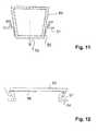
- FIG. 11shows a sewing ring 51, which itself has a conical inner contour, but may also have a cylindrical inner contour.
- a conical plug 50may be hollow and made of a plastic, elastomer or a metal, also a foamed metal, an open-pore Metal structure and in particular titanium exist.
- the plugmay be gas filled and is forced axially in the direction of arrow 53 into the mouth of the sewing ring.
- the plugmay be textured on its periphery at least partially, in particular in the sealing area, on its surface or coated with a textured fabric to promote ingrowth (see reference numeral 52).
- FIG. 12shows a sewing ring 54 having a conical outer contour 57, on which a circumferential rim of the elastic closure element 55 is clamped to seal either there in the region of the lateral surface of the sewing ring or at its end face.
- the closure element 55may be wholly or partially provided with a texturing 56 or consist for example of an open-pore metal structure or a metal foam or metal fabric.
Landscapes
- Health & Medical Sciences (AREA)
- Heart & Thoracic Surgery (AREA)
- Engineering & Computer Science (AREA)
- Life Sciences & Earth Sciences (AREA)
- Cardiology (AREA)
- Biomedical Technology (AREA)
- General Health & Medical Sciences (AREA)
- Animal Behavior & Ethology (AREA)
- Veterinary Medicine (AREA)
- Public Health (AREA)
- Anesthesiology (AREA)
- Hematology (AREA)
- Mechanical Engineering (AREA)
- Vascular Medicine (AREA)
- Surgery (AREA)
- Pulmonology (AREA)
- Nuclear Medicine, Radiotherapy & Molecular Imaging (AREA)
- Reproductive Health (AREA)
- Molecular Biology (AREA)
- Medical Informatics (AREA)
- Transplantation (AREA)
- Oral & Maxillofacial Surgery (AREA)
- Prostheses (AREA)
- Surgical Instruments (AREA)
Abstract
Translated fromGermanDescription
Translated fromGermanDie Erfindung liegt auf dem Gebiet des Maschinenbaus und der Mechanik und ist mit besonderem Vorteil im Bereich der Medizintechnik einsetzbar.The invention is in the field of mechanical engineering and mechanics and can be used with particular advantage in the field of medical technology.
Konkreter bezieht sich die Erfindung auf eine Anschlusseinrichtung, mit der rohr- oder schlauchförmige Elemente an einen Hohlraum, insbesondere ein Herz oder Blutgefäß im Körper eines Patienten, angeschlossen werden können. Solche Aufgaben stellen sich beispielsweise bei einem vorübergehenden oder dauerhaften Anschluss einer Pumpe an ein Blutgefäß oder direkt an das Herz eines Patienten. Bei solchen Anwendungen wird eine Kanüle oder ein Pumpenrohr unmittelbar an einer Herzwand oder einer Gefäßwand befestigt und durch diese Wand möglichst fluiddicht durchgeführt.More specifically, the invention relates to a connection device with which tubular or tubular elements can be connected to a cavity, in particular a heart or blood vessel in the body of a patient. Such tasks arise, for example, in a temporary or permanent connection of a pump to a blood vessel or directly to the heart of a patient. In such applications, a cannula or a pump tube is attached directly to a heart wall or vessel wall and carried through this wall as fluid-tight as possible.
Zu diesem Zweck ist es bereits bekannt, sogenannte Nahtringe zu verwenden, wobei ein Nahtring üblicherweise einen festen ringförmigen Körper, beispielsweise aus einem Metall, sowie einen mit diesem Körper verbundenen flexiblen Teil aufweist, der mittels üblicher Befestigungsmethoden an dem organischen Gewebe befestigbar ist, das die von dem Rohr oder Schlauch durchsetzte Öffnung umgibt. Beispielsweise kann diese Befestigung durch Vernähen mittels eines Fadens oder Verkleben oder Verschweißen hergestellt werden. Durch den Nahtring wird dann üblicherweise ein Rohrstutzen, ein Schlauch oder eine Kanüle gedichtet hindurchgeführt.For this purpose, it is already known to use so-called sewing rings, wherein a sewing ring usually a solid annular body, such as a metal, as well as one connected to this body flexible part, which is fastened by means of conventional attachment methods to the organic tissue surrounding the penetrated by the tube or tube opening. For example, this attachment can be made by sewing by means of a thread or gluing or welding. By the sewing ring is then usually sealed a pipe socket, a hose or a cannula passed.
In einigen Fällen wird die entsprechende Öffnung im Gewebe vorübergehend oder endgültig nicht mehr benötigt, so dass es vorteilhaft ist, diese zu verschließen. Es kann in einigen Fällen hierzu vorteilhaft sein, den Nahtring am Gewebe zu belassen und die Öffnung im Nahtring zu verschließen. Dabei wird eine weitere Beschädigung von organischem Gewebe vermieden, und die Öffnung kann dicht an dem Nahtring verschlossen werden, wenn ein entsprechender Verschlussmechanismus gewählt wird. Eventuelle Unwägbarkeiten beim Verbinden oder Verschließen von organischem Gewebe treten dann nicht auf. Zudem kann der verschlossene Nahtring später auch wieder ohne großen Aufwand geöffnet werden.In some cases, the corresponding opening in the tissue is temporarily or permanently no longer needed, so it is advantageous to close them. In some cases, it may be advantageous to leave the sewing ring on the tissue and to close the opening in the sewing ring. In this case, further damage to organic tissue is avoided, and the opening can be sealed close to the sewing ring, if a corresponding closure mechanism is selected. Any imponderables when connecting or closing organic tissue will not occur. In addition, the sealed sewing ring can later be opened again without much effort.
Aus dem Stand der Technik ist beispielsweise im Rahmen der
Der vorliegenden Erfindung liegt vor dem Hintergrund des Standes der Technik die Aufgabe zugrunde, eine Anschlusseinrichtung für den Anschluss eines rohr- oder schlauchförmigen Elementes an das Herz oder ein Blutgefäß eines Patienten zu schaffen, die mit möglichst geringem konstruktivem Aufwand in möglichst sicherer und zuverlässiger Weise den Verschluss einer Öffnung zulässt, wobei zudem der Aufwand beim Verschließen der Öffnung gering gehalten und der Patient möglichst weitgehend geschont werden soll.The present invention is based on the background of the prior art, the task of providing a connection device for connecting a tubular or tubular element to the heart or a blood vessel of a patient with the least possible design effort in the safest and most reliable way Closure of an opening allows, while also keeping the cost of closing the opening low and the patient should be spared as much as possible.
Die Aufgabe wird mit den Merkmalen der Neuerung gemäß Patentanspruch 1 gelöst. Weitere Ausgestaltungen der Neuerung sind den Unteransprüchen 2 bis 15 zu entnehmen.The object is achieved with the features of the innovation according to
Die Neuerung bezieht sich mithin auf eine Anschlusseinrichtung für den Anschluss eines rohr- oder schlauchförmigen Elementes an das Herz oder ein Blutgefäß eines Patienten mit einem Nahtring, der eine durch ein Verschlusselement verschließbare Öffnung zur Durchführung des rohr- oder schlauchförmigen Elementes in Axialrichtung aufweist. Die Aufgabe wird gemäß der Neuerung dadurch gelöst, dass das Verschlusselement durch wenigstens ein elastisches Befestigungselement an dem Nahtring befestigt ist.The innovation therefore relates to a connection device for the connection of a tubular or tubular element to the heart or a blood vessel of a patient with a sewing ring which has a closable by a closure element opening for the passage of the tubular or tubular element in the axial direction. The object is achieved according to the innovation in that the closure element is secured by at least one elastic fastening element to the sewing ring.
Durch das elastische Befestigungselement kann einerseits mittels einer Klemmeinrichtung ohne größeren Aufwand ein Verschlusselement an einem Nahtring befestigt werden, und andererseits kann das Befestigungselement potenziell wegen seiner Elastizität wenigstens teilweise auch als Dichtelement dienen. Hierdurch ist eine Befestigung des Verschlusselementes am Nahtring möglich, ohne dass der Nahtring in größerem Maß bewegt oder manipuliert werden muss. Die Befestigung durch das elastische Befestigungselement funktioniert dauerhaft und garantiert den mechanischen Halt des Verschlusselementes unabhängig von Bewegungen des Patienten und Änderung der Umgebungsbedingungen. Insbesondere ist eine Verbindung mittels eines elastischen Befestigungselementes in einfacher Weise und ohne größere Belastung des Patienten mit einem minimalen Eingriff in den Körper des Patienten herzustellen. Das Verschlusselement kann an einer Stirnfläche des Nahtrings oder an einer insbesondere zylindrischen Innenfläche dichtend anliegen. Es ist generell auch denkbar, dass das Verschlusselement an einer äußeren Umfangsfläche des Nahtrings dichtend anliegt.The elastic fastening element on the one hand by means of a clamping device without much effort, a closure element can be attached to a sewing ring, and on the other hand, the fastener potentially because of its elasticity at least partially serve as a sealing element. As a result, an attachment of the closure element to the sewing ring is possible without the sewing ring has to be moved or manipulated to a greater extent. The attachment by the elastic fastener works permanently and guarantees the mechanical hold of the closure element, regardless of movements of the patient and change of environmental conditions. In particular, a connection by means of an elastic fastening element in a simple manner and without greater burden on the patient with minimal intervention in the body of the patient to produce. The closure element may rest sealingly against an end face of the sewing ring or on a particular cylindrical inner surface. It is also generally conceivable that the closure element bears sealingly against an outer peripheral surface of the sewing ring.
Eine Ausgestaltung der Neuerung sieht vor, dass das Verschlusselement ein an seinem äußeren Umfang an dem Nahtring dichtendes Dichtelement sowie eine Einrichtung zur Aufweitung des Dichtelementes in Radialrichtung des Nahtrings aufweist. Das Dichtelement ist üblicherweise verformbar, insbesondere elastisch, und kann beispielsweise aus einem Elastomer bestehen oder ein Elastomer aufweisen. Es kann beispielsweise auch aus einem plastisch verformbaren Stoff mit Klebeigenschaften, typischerweise einem Kleber, bestehen oder mittels eines Klebers mit dem Nahtring verbunden sein. Es kann beispielsweise an einer zylindrischen oder anders geformten Innenfläche des Nahtrings oder an anderen Flächen des Nahtrings, beispielsweise an einer Stirnfläche, einer Schräge oder in einer Nut des Nahtrings, durch dichte Anlage dichten. Das Dichtelement kann beispielsweise mit dem Befestigungselement identisch oder Teil des Befestigungselementes sein; es kann jedoch auch unabhängig vom Befestigungselement vorgesehen sein.An embodiment of the invention provides that the closure element has a sealing element which seals at its outer circumference on the sewing ring and a device for widening the sealing element in the radial direction of the sewing ring. The sealing element is usually deformable, in particular elastic, and may for example consist of an elastomer or comprise an elastomer. For example, it can also be made of a plastically deformable material with adhesive properties, typically an adhesive, exist or be connected by means of an adhesive to the sewing ring. For example, it may be sealed against a cylindrical or otherwise shaped inner surface of the sewing ring or on other surfaces of the sewing ring, for example on an end face, a slope or in a groove of the sewing ring. The sealing element may for example be identical or part of the fastening element with the fastening element; However, it may also be provided independently of the fastener.
Das Dichtelement kann massiv oder hohl ausgebildet sein, beispielsweise als Hohlkörper mit einem zentralen Hohlraum oder auch als geschlossen- oder offenporiger Schaumstoff, oder es kann einen solchen Schaumstoff aufweisen. Möglich ist (dies gilt für alle Ausführungsformen der vorliegenden Schutzrechtsanmeldung) statt eines Schaumstoffs auch offenporiges Textilgewebe zum Fördern des Anwachsens von organischem, insbesondere menschlichem Gewebe. Dies kann beispielsweise Graft- und/oder Velours-Material umfassen.The sealing element may be solid or hollow, for example as a hollow body with a central cavity or as a closed or open-cell foam, or it may have such a foam. It is possible (this applies to all embodiments of the present patent application) instead of a foam and open-cell textile fabric to promote the growth of organic, especially human tissue. This may include graft and / or velor material, for example.
Das Dichtelement, das Befestigungselement und das Verschlusselement können jeweils ganz oder teilweise aus einem Metall oder einem Kunststoff bestehen, ebenso aus einem aufgeschäumten Material, beispielsweise auch Metallschaum aus einer offenporigen Metallstruktur. Ein in Frage kommendes Metall ist dabei Titan. Die Oberflächen oder Oberflächenbereiche können (dies gilt für alle in diesem Absatz genannten Elemente) dabei derart texturiert sein, dass das Einwachsen begünstigt wird. Auch Textilgewebe oder sonstiges Gewebe kann mit oder ohne Texturierung verwendet werden.The sealing element, the fastening element and the closure element may each consist wholly or partly of a metal or a plastic, as well as a foamed material, such as metal foam of an open-pore metal structure. A candidate metal is titanium. The surfaces or surface areas (this applies to all elements mentioned in this paragraph) can be textured in such a way that ingrowth is favored. Also textile fabric or other fabric can be used with or without texturing.
Allgemein kommen für die genannten Bauteile biokompatible Materialien in Frage, die einwachsfähig sind.In general come for the components mentioned biocompatible materials in question, which are einwachsfähig.
Eine weitere Lösung im Rahmen der vorliegenden Neuerung kann vorsehen, dass das Dichtelement in Axialrichtung komprimierbar und dadurch in radialer Richtung aufweitbar ist. Diese Lösung kann beispielsweise vorsehen, dass das Dichtelement aus einem nicht volumenkompressiblen Elastomer besteht und beispielsweise ringförmig ausgebildet ist, oder auch, dass das Dichtelement ein hohles Elastomerelement ist oder umfasst, das unter Komprimierung eines im Hohlraum befindlichen Mediums verformt werden kann.Another solution in the context of the present innovation may provide that the sealing element is compressible in the axial direction and thereby expandable in the radial direction. This solution can provide, for example, that the sealing element consists of a non-volume-compressible elastomer and, for example, is annular, or also that the sealing element is or comprises a hollow elastomer element, which can be deformed under compression of a medium located in the cavity.
Weiter kann im Rahmen der Neuerung vorgesehen sein, dass das Verschlusselement eine an seinem Umfang umlaufende Ausnehmung für das in Axialrichtung komprimierbare Dichtelement aufweist. Es kann beispielsweise das Verschlusselement ein scheibenförmiges oder topfförmiges Element aufweisen, das an seinem Umfang eine entsprechende Ausnehmung aufweist, die beispielsweise als umlaufende Nut ausgebildet sein kann.Furthermore, it can be provided in the context of the innovation that the closure element has a circumferential recess for the compressible in the axial direction of the sealing element. By way of example, the closure element may have a disk-shaped or cup-shaped element which has a corresponding recess on its circumference, which may be designed, for example, as a peripheral groove.
Die Außenkontur des Verschlusselements kann dabei rund, insbesondere kreisrund, sein, sie kann jedoch auch elliptisch oder viereckig oder mehreckig (polygon), jeweils beispielsweise unter Abrundung der Ecken, gestaltet sein. Der Begriff "radial" bedeutet in diesem Fall z. B. vom Flächenschwerpunkt oder Flächenmittelpunkt nach außen zum Umfang gerichtet.The outer contour of the closure element may be round, in particular circular, but it may also be elliptical or quadrangular or polygonal, in each case, for example, rounding off the corners. The term "radial" in this case means z. B. directed from the centroid or area center outwards to the circumference.
Es kann auch als implementierbare Lösung vorgesehen sein, dass das Verschlusselement wenigstens zwei gesonderte und in Axialrichtung gegeneinanderpressbare Elemente aufweist, zwischen denen ein radial nach außen offener Zwischenraum, insbesondere eine am Umfang des Verschlusselements umlaufende Nut, zur Aufnahme des Dichtelementes gebildet ist. Das Verschlusselement kann hierzu zwei in Axialrichtung, d. h. in Durchgangsrichtung der Anschlusseinrichtung, hintereinander liegende und gegeneinander in Axialrichtung bewegliche Elemente aufweisen, zwischen denen ein massives oder hohles Elastomerelement als Dichtelement angeordnet sein kann. Die gegeneinanderpressbaren Elemente können beispielsweise als flache Scheiben oder kalottenartige Körper ausgebildet sein, oder es kann einer der Körper als Scheibe und der andere Körper als gegen die Scheibe pressbarer Stempel ausgebildet sein. Das Dichtelement kann auf ganzer Breite zwischen den beiden gegeneinanderpressbaren Elementen liegen oder als ringförmiger Körper ausgebildet sein.It can also be provided as an implementable solution that the closure element has at least two separate and axially compressible against each other elements between which a radially outwardly open space, in particular a circumferential groove on the circumference of the closure element, is formed for receiving the sealing element. The closure element can for this purpose two in the axial direction, d. H. in the passage direction of the connection device, one behind the other and have mutually axially movable elements, between which a solid or hollow elastomer element may be arranged as a sealing element. The elements which can be pressed against one another can be designed, for example, as flat disks or dome-like bodies, or one of the bodies can be in the form of a disk and the other body can be formed as a stamp which can be pressed against the disk. The sealing element can lie across the entire width between the two elements which can be pressed against one another or be designed as an annular body.
Bei einer axialen Pressung wird das Dichtelement radial nach außen expandiert, bis es gegen eine Dichtfläche des Nahtrings stößt und dort dichtet. In einer besonderen Ausbildung der Neuerung kann am Umfang des Verschlusselementes eine umlaufende Nut zur Aufnahme des Dichtelementes gebildet sein. Die Nut kann dann derart verformbar sein, dass die Breite der Nut in Axialrichtung verringerbar ist, so dass das Dichtelement aus der Nut heraus und in radialer Richtung nach außen gegen den Nahtring drückbar ist. Dies kann beispielsweise dadurch realisiert sein, dass die verschiedenen Seitenwände der Nut durch die verschiedenen gegeneinanderpressbaren Elemente gebildet sind.In an axial pressure, the sealing element is expanded radially outward until it abuts against a sealing surface of the sewing ring and seals there. In a particular embodiment of the invention, a circumferential groove for receiving the sealing element can be formed on the circumference of the closure element. The groove can then be deformable such that the width of the groove in the axial direction can be reduced, so that the sealing element out of the groove out and in the radial direction can be pressed outwards against the sewing ring. This can be realized, for example, in that the different side walls of the groove are formed by the various elements which can be pressed against each other.
Insbesondere für den Fall, dass an dem Verschlusselement eine radial außen umlaufende Nut angeordnet ist, kann weiterhin vorgesehen sein, dass am Boden der Nut wenigstens an einem der beiden gegeneinanderpressbaren Elemente eine umlaufende und radial nach außen weisende Schräge gebildet ist und dass insbesondere der Boden der Nut im Querschnitt V-förmig ausgebildet ist, wobei jeder der beiden Schenkel des V-förmigen Bodens von einem der Elemente gebildet ist. Eine derartige Ausformung der Nut fördert speziell die Umsetzung einer Kompression des Dichtelementes in Axialrichtung in eine Expansion in Radialrichtung nach außen.In particular, in the event that a radially outwardly encircling groove is disposed on the closure element, can further be provided that at the bottom of the groove at least one of the two gegeneinanderpressbaren elements a circumferential and radially outwardly facing slope is formed and that in particular the bottom of the Groove in cross-section V-shaped, wherein each of the two legs of the V-shaped bottom is formed by one of the elements. Such a formation of the groove promotes specifically the implementation of a compression of the sealing element in the axial direction in an expansion in the radial direction to the outside.
Die beiden gegeneinanderpressbaren Elemente können durch verschiedene Mechanismen axial gegeneinandergedrückt werden, beispielsweise dadurch, dass eines der Elemente an einem Anschlag des Nahtrings anliegt und das zweite Element durch Klemmelemente gegen das erste Element gepresst wird, die an den Nahtring abgestützt sind. Soll eine Kompression der beiden gegeneinanderpressbaren Elemente möglichst einfach und ohne eine Bewegung des Nahtrings bzw. ohne eine Belastung des Nahtrings mit Kräften geschehen, so kann beispielsweise vorgesehen sein, dass die beiden gegeneinanderpressbaren Elemente durch eine zentrale Schraubverbindung miteinander verbunden sind. Damit müssen nur die beiden gegeneinanderpressbaren Elemente miteinander oder mit einem dritten Element verschraubt werden, wobei Kräfte auf den Nahtring entweder gar nicht auftreten oder in engen Grenzen gehalten werden können.The two elements which can be pressed against each other can be pressed axially against one another by various mechanisms, for example in that one of the elements bears against a stop of the sewing ring and the second element is pressed against the first element by clamping elements, which are supported on the sewing ring. If compression of the two elements which can be pressed against one another is to be done as simply as possible and without movement of the sewing ring or without stressing the sewing ring with forces, it can be provided, for example, that the two elements which can be pressed against each other are connected to one another by a central screw connection. Thus, only the two gegeneinanderpressbaren elements must be bolted together or with a third element, with forces on the sewing ring either not occur or can be kept within narrow limits.
Konkret kann hierzu beispielsweise vorgesehen sein, dass wenigstens ein Gewindestift eine Öffnung eines der gegeneinanderpressbaren Elemente ohne Gewindeeingriff durchsetzt und dass wenigstens eine Gewindemutter auf den Gewindestift zum Gegeneinanderpressen der Elemente des Verschlusselements schraubbar ist. Eine derartige Schraubverbindung ist einerseits zum Komprimieren des Dichtelementes leicht spannbar und andererseits ebenso leicht wieder lösbar, um das Verschlusselement beispielsweise wieder zu entfernen. Außerdem ist durch die Schraubverbindung die auf das Dichtelement wirkende Kraft stufenlos einstellbar. Das Gewinde der Schraubverbindung sollte eine derart flache Steigung haben, dass die Schraubverbindung selbsthemmend ist.Concretely, this can be provided, for example, that at least one threaded pin passes through an opening of one of the gegeneinanderpressbaren elements without threaded engagement and that at least one threaded nut can be screwed onto the threaded pin for pressing against each other of the elements of the closure element. Such a screw connection is on the one hand easily compressible for compressing the sealing element and on the other hand just as easily releasable, for example, the closure element again to remove. In addition, the force acting on the sealing element is infinitely adjustable by the screw connection. The thread of the screw should have such a flat slope that the screw is self-locking.
Es kann im Rahmen der Neuerung auch vorgesehen sein, dass die beiden gegeneinanderpressbaren Elemente ineinandergreifende zentrische Gewinde aufweisen und gegeneinander verdrehbar sind. In diesem Fall kann eines der beiden gegeneinanderpressbaren Elemente ein Außengewinde und das andere Element ein Innengewinde aufweisen, die unmittelbar miteinander verschraubt sind. Diese Gewinde können entweder im Bereich des äußeren Umfangs des Verschlusselements oder auch radial weiter innen an entsprechend vorgesehenen Stutzen bzw. rohrförmigen Elementen vorgesehen sein,It can also be provided in the context of the innovation, that the two gegeneinanderpressbaren elements have intermeshing central thread and are mutually rotatable. In this case, one of the two gegenpresspressbaren elements have an external thread and the other element having an internal thread, which are bolted directly together. These threads can be provided either in the region of the outer circumference of the closure element or also radially further inwards on correspondingly provided nozzles or tubular elements,
Allgemein kann auch für den Fall, dass kein Gewinde zwischen den gegeneinanderpressbaren Elementen vorhanden ist, vorgesehen sein, dass die beiden gegeneinanderpressbaren Elemente eine Führungseinrichtung zur Führung ihrer Relativbewegung in Axialrichtung aufweisen. Dies ist insbesondere dann wichtig, wenn der axiale Pressdruck durch Klemmelemente realisiert wird, die selbst keine Führung der beiden gegeneinanderpressbaren Elemente in Axialrichtung bewirken.In general, even in the event that no thread is present between the elements which can be pressed against one another, it can be provided that the two elements which can be pressed against one another have a guide device for guiding their relative movement in the axial direction. This is particularly important when the axial pressing pressure is realized by clamping elements, which in themselves cause no guidance of the two gegenpresspressbaren elements in the axial direction.
Jedenfalls kann auch vorgesehen sein, dass an dem Verschlusselement ein Anschlag zur Begrenzung der Relativbewegung der beiden gegeneinanderpressbaren Elemente in Axialrichtung vorgesehen ist. Hierdurch wird die Kompression des Dichtelementes in axialer Richtung begrenzt, so dass beispielsweise das Risiko einer Zerstörung des Dichtelementes oder eines vollständigen Herausdrückens des Dichtelementes aus dem Zwischenraum zwischen den gegeneinanderpressbaren Elementen begrenzt ist.In any case, it can also be provided that a stop for limiting the relative movement of the two elements which can be pressed against one another in the axial direction is provided on the closure element. As a result, the compression of the sealing element is limited in the axial direction, so that, for example, the risk of destruction of the sealing element or a complete squeezing out of the sealing element from the intermediate space between the gegeneinanderpressbaren elements is limited.
Eine vorteilhafte Ausgestaltung der Neuerung kann beispielsweise vorsehen, dass das Dichtelement eine Elastomerdichtung mit insbesondere kreisrundem, ovalem, dreieckigem oder viereckigem Querschnitt ist. Die Elastomerdichtung kann beispielsweise aus einem Gummi, einem Silikonelastomer, einem offenporigen Textilgewebe (z. B. einem Velours- oder Graftmaterial) oder einem anderen vergleichbaren Stoff bestehen und beispielsweise auch als geschlossen- oder offenporiger Schaumstoff oder als texturiertes Material ausgestaltet sein. Weiter ist es auch möglich, dass die Elastomerdichtung einen oder mehrere Hohlräume aufweist, die mit einem Fluid, einem Gel oder einem Gas gefüllt sind, wobei der Hohlraum geschlossen und verformbar sein kann. Es kann auch das Einfüllen eines Mediums in den Hohlraum zur Verformung des Dichtelementes vorgesehen sein.An advantageous embodiment of the innovation may for example provide that the sealing element is an elastomeric seal with in particular circular, oval, triangular or square cross-section. The elastomeric seal can be made, for example, of a rubber, a silicone elastomer, an open-pore textile fabric (eg a velor or graft material). or another comparable material and be designed, for example, as closed or open-cell foam or as a textured material. Furthermore, it is also possible that the elastomeric seal has one or more cavities which are filled with a fluid, a gel or a gas, wherein the cavity can be closed and deformable. It may also be provided the filling of a medium in the cavity for deformation of the sealing element.
Hierzu kann beispielsweise an dem Dichtelement eine Fülleinrichtung vorgesehen sein, die öffenbar und verschließbar ist. Es kann beispielsweise in den Hohlraum eines derartigen Dichtelementes auch ein Stoff eingefüllt werden, der zunächst fließfähig ist und dessen Einfüllen zu einer radialen Expansion des Dichtelementes führt, wobei der Stoff später aushärtbar oder versteifbar ist, um das Dichtelement im expandierten Zustand zu verfestigen. Ein solcher Stoff kann beispielsweise auch mittels einer Injektionsnadel ohne eine gesonderte Fülleinrichtung in den Hohlraum eines Dichtelementes eingespritzt werden.For this purpose, for example, a filling device can be provided on the sealing element, which can be opened and closed. It can be filled, for example, in the cavity of such a sealing element, a substance which is initially flowable and its filling leads to a radial expansion of the sealing element, wherein the material is later curable or stiffenable to solidify the sealing element in the expanded state. Such a substance can for example also be injected into the cavity of a sealing element by means of an injection needle without a separate filling device.
In diesem Zusammenhang soll festgehalten werden, dass eine mögliche Ausgestaltung der Neuerung vorsehen kann, dass das Dichtelement ein verformbarer, insbesondere elastischer und mit einem Gas, einer Flüssigkeit oder einem Gel füllbarer Hohlkörper, insbesondere in Torus- oder Kugelform, ist.In this context, it should be noted that a possible embodiment of the innovation can provide that the sealing element is a deformable, in particular elastic and can be filled with a gas, a liquid or a gel hollow body, in particular in torus or spherical shape.
Grundsätzlich kann die Anschlusseinrichtung auch derart gestaltet sein, dass das Verschlusselement einen von einer elastischen Wand umgebenen Hohlraum aufweist, der zusammen mit der elastischen Wand durch Einschieben eines zapfenartigen Körpers oder durch Spreizen eines Spreizelementes innerhalb des Hohlraums radial aufweitbar ist. Dazu kann beispielsweise das Verschlusselement ein Dichtelement in Form eines Torus oder eines Dichtungsrings aufweisen, in dessen axialer Durchgangsöffnung ein zapfenförmig oder konisch sich erweiternder Körper eingeschoben wird, der den torusförmigen Körper in Bezug auf seine Symmetrieachse radial aufweitet.In principle, the connection device can also be designed such that the closure element has a cavity surrounded by an elastic wall, which is radially expandable together with the elastic wall by inserting a pin-like body or by spreading a spreading element within the cavity. For this purpose, for example, the closure element may comprise a sealing element in the form of a torus or a sealing ring, in the axial passage opening a peg-shaped or conically expanding body is inserted, which radially widens the toroidal body with respect to its axis of symmetry.
Es kann jedoch auch ein Spreizelement innerhalb des Hohlraums eines Dichtelementes vorgesehen sein, das von außen betätigbar ist, so dass die den Hohlraum begrenzenden Wände des Dichtelementes radial nach außen erweitert werden, bis sie an einer Dichtfläche des Nahtrings dichten.However, it can also be provided an expansion element within the cavity of a sealing element which can be actuated from the outside, so that the the cavity bounding walls of the sealing element are expanded radially outward until they seal at a sealing surface of the sewing ring.
Im Folgenden wird die Neuerung anhand von Ausführungsbeispielen in Figuren einer Zeichnung gezeigt und nachfolgend erläutert. Dabei zeigt
- Fig. 1
- in einem schematischen Schnitt eine Anschlusseinrichtung mit einem Dichtungsring, der als Befestigungselement und als Dichtelement dient,
- Fig. 2
- eine Anschlusseinrichtung mit einem hohlen Dichtungsring,
- Fig. 3
- eine Anschlusseinrichtung mit einem elastischen Deckel,
- Fig. 4
- eine Anschlusseinrichtung mit einem Deckel, der elastische Haken aufweist,
- Fig. 5a
- in einem Halbschnitt eine Anschlusseinrichtung mit einem Deckel und einer Überwurfmutter,
- Fig. 5b
- einen Federring als Detail aus
Figur 5a , - Fig. 6
- im Schnitt eine Anschlusseinrichtung mit einem hohlen Gummikörper,
- Fig. 7
- eine Anschlusseinrichtung mit einem hohlen verdrehbaren Gummikörper,
- Fig. 8
- eine Anschlusseinrichtung mit einem hohlen Dichtelement und einer Spreizvorrichtung,
- Fig. 9
- eine Anschlusseinrichtung mit einem Ventil, auf der rechten Seite mit einem eingefügten Pumpenrohr,
- Fig. 10
- eine Anschlusseinrichtung mit einem hohlen Dichtungsring und einem in diesen einführbaren Zapfen zur Aufweitung,
- Fig. 11
- eine Anschlusseinrichtung mit einem konischen Stopfen, der unmittelbar in die Öffnung des Nahtrings gedrückt werden kann, sowie
- Fig. 12
- eine Anschlusseinrichtung mit einem Stopfen, der radial außen auf eine Außenfläche des Nahtrings aufgeklemmt ist.
- Fig. 1
- in a schematic section a connection device with a sealing ring, which serves as a fastening element and as a sealing element,
- Fig. 2
- a connection device with a hollow sealing ring,
- Fig. 3
- a connection device with an elastic lid,
- Fig. 4
- a connection device with a lid which has elastic hooks,
- Fig. 5a
- in a half section a connection device with a cover and a union nut,
- Fig. 5b
- a spring washer as a detail
FIG. 5a . - Fig. 6
- in section a connection device with a hollow rubber body,
- Fig. 7
- a connection device with a hollow rotatable rubber body,
- Fig. 8
- a connection device with a hollow sealing element and a spreading device,
- Fig. 9
- a connection device with a valve, on the right side with an inserted pump tube,
- Fig. 10
- a connection device with a hollow sealing ring and an insertable into this pin for widening,
- Fig. 11
- a connection device with a conical plug, which can be pressed directly into the opening of the sewing ring, as well as
- Fig. 12
- a connection device with a plug, which is clamped radially outward on an outer surface of the sewing ring.
Der Nahtring 2 weist eine zentrische zylindrische Öffnung 6 auf, durch die im Betrieb einer Herzpumpe ein Rohr, eine Kanüle oder ein Schlauch hindurchgeführt und dort üblicherweise gedichtet ist. In der Darstellung der
Um ein axiales Zusammenpressen der Elemente 8, 9 zu gewährleisten, ist mit dem Element 8 eine Gewindestange 12 verbunden, die durch eine zentrische Öffnung in dem Element 9 hindurchragt und auf die eine Gewindemutter 13 aufschraubbar ist. Das Element 9 weist eine Krempe 14 auf, die über den Rand des metallischen Teils 3 des Nahtrings 2 hinüberragt. Beim Manipulieren des Verschlusselementes 7 kann beispielsweise ein Operateur an der Krempe 14 das Verschlusselement fassen und die Gewindemutter 13 drehen, um die Elemente 8, 9 gegeneinanderzupressen oder beim Lösen der Mutter 13 voneinander zu lösen. Den eigentlichen Nahtring 2 muss der Operateur beim Anbringen und Lösen des Verschlusselementes 7 nicht notwendigerweise anfassen, und die auf den Nahtring 2 wirkenden Kräfte während des Verschluss- oder Lösevorgangs sind begrenzt. Damit wird das Risiko, dass der weiche Teil 4 des Nahtrings 2 sich von dem organischen Gewebe 5 der Herzwand löst, minimiert.In order to ensure an axial compression of the
Der Dichtring 10 kann beispielsweise aus Gummi oder einem Silikonelastomer bestehen und im Querschnitt fast beliebige Formen annehmen, die nur zur Form der Nut 8a, 9a passen müssen, die zwischen den Elementen 8, 9 gebildet ist. Günstige Querschnitte können beispielsweise dreieckig, kreisrund oder elliptisch sein.The sealing
Alternativ sind schematisch Federklemmen 16, 17 gestrichelt angedeutet, die zusätzlich zu dem oder anstelle des Kompressionsmechanismus, der aus der Gewindestange 12' und der Mutter 13' besteht, vorgesehen sein können, um die Elemente 8', 9' axial zu komprimieren.Alternatively, spring clamps 16, 17 are schematically indicated by dashed lines, which may be provided in addition to or instead of the compression mechanism consisting of the threaded rod 12 'and the nut 13' in order to axially compress the elements 8 ', 9'.
Zudem ist in
Der elastische Deckel 7" kann aus einem texturierten Material, wie beispielsweise einem oberflächentexturierten Metall, z. B. Titan, einem Metallschaum, einem Textil oder Gewebe, bestehen, das das Einwachsen begünstigt. Dabei ist auch denkbar, dass der Deckel erst durch das Einwachsen dicht wird. Die Texturierung oder Abdeckung mit einem Textil oder Gewebe ist in
Die in den
Die topfartigen Körper 25a, 26a weisen zur Fixierung an dem jeweiligen Nahtring eine oder mehrere radiale Erweiterungen 25e, 25f bzw. 26e auf, die auf einer oder beiden Seiten des Nahtrings in Axialrichtung jeweils Anschläge bilden und damit ein Herausrutschen der Verschlusselemente 25, 26 aus der Öffnung des jeweiligen Nahtrings in Axialrichtung verhindern.The pot-
Die Stützen 25d, 26d können beispielsweise Verdickungen wie in
Innerhalb der topfartigen Körper 25a, 26a können, eingelassen in eine Wand des jeweiligen Körpers, federnde Stützelemente in Form von Drahtringen eingelassen sein, die bei Wegfallen einer Torsionskraft elastisch auf die Wiederherstellung des expandierten Zustands hinwirken. In
Soll ein Pumpenrohr 40 oder ein schlauchartiger oder kanülenartiger Gegenstand durch die Öffnung 39 hindurchgeschoben werden, so weichen die Schwenkelemente 38 zurück und machen für den eingeschobenen Gegenstand Platz, wie im rechten Teil der Darstellung der
Teile des Rohrstutzens 35a, insbesondere an seiner Außenseite, können eine texturierte Metalloberfläche, insbesondere eine texturierte Titanoberfläche aufweisen, die das Zellwachstum nach einer Implantation in einen lebenden Organismus fördert und damit das Einwachsen und auch die Abdichtung durch lebendes Gewebe beschleunigt. Eine solche Texturierung kann auch an den bereits oben beschriebenen festen, insbesondere metallischen Teilen der Verschlusselemente vorgesehen sein, um jeweils nach einem Einbringen in einen Patientenkörper das Einwachsen zu erleichtern bzw. zu beschleunigen.Parts of the
Die in den Ansprüchen definierten und anhand der Ausführungsbeispiele dargestellten Realisierungen der Neuerung erlauben ein Verschließen der Öffnung eines Nahtrings unter Vermeidung zu starker Bewegungen oder Krafteinwirkungen auf den Nahtring, so dass ein Verschluss durch ein Verschlusselement jeweils ohne Gefährdung des Patienten und mit minimaler Einwirkung ermöglicht ist.The realizations of the innovation defined in the claims and illustrated by the embodiments allow the opening of a sewing ring to be closed while avoiding strong movements or force effects on the sewing ring, so that closure by a closure element is possible without endangering the patient and with minimum impact.
Claims (15)
Translated fromGermanPriority Applications (6)
| Application Number | Priority Date | Filing Date | Title |
|---|---|---|---|
| EP15196333.7AEP3173107A1 (en) | 2015-11-25 | 2015-11-25 | Attachment device |
| PCT/EP2016/072664WO2017089004A1 (en) | 2015-11-25 | 2016-09-23 | Connecting device |
| DE112016005396.7TDE112016005396A5 (en) | 2015-11-25 | 2016-09-23 | connecting device |
| CN201680068335.4ACN108289986B (en) | 2015-11-25 | 2016-09-23 | Connecting device |
| US15/977,573US11766555B2 (en) | 2015-11-25 | 2018-05-11 | Connecting device |
| US18/366,456US12364851B2 (en) | 2015-11-25 | 2023-08-07 | Connecting device |
Applications Claiming Priority (1)
| Application Number | Priority Date | Filing Date | Title |
|---|---|---|---|
| EP15196333.7AEP3173107A1 (en) | 2015-11-25 | 2015-11-25 | Attachment device |
Publications (1)
| Publication Number | Publication Date |
|---|---|
| EP3173107A1true EP3173107A1 (en) | 2017-05-31 |
Family
ID=54707574
Family Applications (1)
| Application Number | Title | Priority Date | Filing Date |
|---|---|---|---|
| EP15196333.7AWithdrawnEP3173107A1 (en) | 2015-11-25 | 2015-11-25 | Attachment device |
Country Status (5)
| Country | Link |
|---|---|
| US (2) | US11766555B2 (en) |
| EP (1) | EP3173107A1 (en) |
| CN (1) | CN108289986B (en) |
| DE (1) | DE112016005396A5 (en) |
| WO (1) | WO2017089004A1 (en) |
Cited By (1)
| Publication number | Priority date | Publication date | Assignee | Title |
|---|---|---|---|---|
| CN113813001A (en)* | 2021-09-24 | 2021-12-21 | 深圳市赛诺思医疗科技有限公司 | Auricle clamp |
Families Citing this family (12)
| Publication number | Priority date | Publication date | Assignee | Title |
|---|---|---|---|---|
| US20190201601A1 (en)* | 2016-09-19 | 2019-07-04 | Evaheart Inc. | Heart cannula |
| DE102018207575A1 (en) | 2018-05-16 | 2019-11-21 | Kardion Gmbh | Magnetic face turning coupling for the transmission of torques |
| DE102018208555A1 (en) | 2018-05-30 | 2019-12-05 | Kardion Gmbh | Apparatus for anchoring a cardiac assist system in a blood vessel, method of operation, and method of making a device and cardiac assist system |
| DE102018208541A1 (en) | 2018-05-30 | 2019-12-05 | Kardion Gmbh | Axial pump for a cardiac assist system and method of making an axial pump for a cardiac assist system |
| DE102018208538A1 (en) | 2018-05-30 | 2019-12-05 | Kardion Gmbh | Intravascular blood pump and process for the production of electrical conductors |
| DE102018208539A1 (en) | 2018-05-30 | 2019-12-05 | Kardion Gmbh | A motor housing module for sealing an engine compartment of a motor of a cardiac assist system and cardiac assistance system and method for mounting a cardiac assist system |
| DE102018208550A1 (en) | 2018-05-30 | 2019-12-05 | Kardion Gmbh | A lead device for directing blood flow to a cardiac assist system, cardiac assist system, and method of making a lead device |
| DE102018210058A1 (en) | 2018-06-21 | 2019-12-24 | Kardion Gmbh | Stator blade device for guiding the flow of a fluid flowing out of an outlet opening of a heart support system, heart support system with stator blade device, method for operating a stator blade device and manufacturing method |
| DE102018210076A1 (en) | 2018-06-21 | 2019-12-24 | Kardion Gmbh | Method and device for detecting a state of wear of a cardiac support system, method and device for operating a cardiac support system and cardiac support system |
| CN112654389A (en) | 2018-08-07 | 2021-04-13 | 开迪恩有限公司 | Bearing device for a cardiac support system and method for flushing an intermediate space in a bearing device for a cardiac support system |
| CN109966014A (en)* | 2019-05-07 | 2019-07-05 | 上海交通大学医学院附属上海儿童医学中心 | Fontan Circulation Assist System Based on Venturi Effect |
| FR3128885B1 (en)* | 2021-11-10 | 2024-12-13 | Fineheart | Device for fixing and positioning a heart pump |
Citations (4)
| Publication number | Priority date | Publication date | Assignee | Title |
|---|---|---|---|---|
| WO2000047270A2 (en)* | 1999-02-12 | 2000-08-17 | Abiomed, Inc. | Medical connector |
| WO2009085243A1 (en)* | 2007-12-27 | 2009-07-09 | Heartware, Inc. | Vad connector plug |
| US20120296358A1 (en)* | 2011-05-18 | 2012-11-22 | John Duc Nguyen | Coring knife |
| WO2014144085A1 (en)* | 2013-03-15 | 2014-09-18 | Apk Advanced Medical Technologies, Inc. | Devices, systems, and methods for implanting and using a connnector in a tissue wall |
Family Cites Families (11)
| Publication number | Priority date | Publication date | Assignee | Title |
|---|---|---|---|---|
| NL1010386C2 (en)* | 1998-10-23 | 2000-04-26 | Eric Berreklouw | Anastomosis device. |
| US8529545B2 (en)* | 2007-09-11 | 2013-09-10 | Asepco | Aseptic connector with lip seal |
| FR2945283B1 (en) | 2009-05-06 | 2015-06-26 | Valois Sas | FIXING DEVICE FOR ATTACHING A PUMP TO A RESERVOIR COLLAR |
| EP2325538A1 (en)* | 2009-11-18 | 2011-05-25 | Berlin Heart GmbH | Device with at least one hollow element for conveying a fluid and with a connection element |
| US10046106B2 (en)* | 2010-10-25 | 2018-08-14 | Bayer Healthcare Llc | Bladder syringe fluid delivery system |
| EP2524709A1 (en)* | 2011-05-16 | 2012-11-21 | Berlin Heart GmbH | Connection system for reversible fixing of a hollow cylindrical component to a recess |
| WO2012158968A2 (en)* | 2011-05-18 | 2012-11-22 | Thoratec Corporation | Needle guard, assembly and method of implanting a heart assist system |
| DE102011117892A1 (en)* | 2011-10-31 | 2013-05-02 | Berlin Heart Gmbh | Connecting element for mounting a blood pump or a cannula on a heart |
| US9981076B2 (en)* | 2012-03-02 | 2018-05-29 | Tc1 Llc | Ventricular cuff |
| CN203724137U (en)* | 2014-01-23 | 2014-07-23 | 苏州同心医疗器械有限公司 | Ventricle connecting assembly |
| EP3113807B1 (en)* | 2014-03-06 | 2019-10-02 | Tc1 Llc | Ventricular cuff |
- 2015
- 2015-11-25EPEP15196333.7Apatent/EP3173107A1/ennot_activeWithdrawn
- 2016
- 2016-09-23DEDE112016005396.7Tpatent/DE112016005396A5/enactivePending
- 2016-09-23WOPCT/EP2016/072664patent/WO2017089004A1/ennot_activeCeased
- 2016-09-23CNCN201680068335.4Apatent/CN108289986B/enactiveActive
- 2018
- 2018-05-11USUS15/977,573patent/US11766555B2/enactiveActive
- 2023
- 2023-08-07USUS18/366,456patent/US12364851B2/enactiveActive
Patent Citations (5)
| Publication number | Priority date | Publication date | Assignee | Title |
|---|---|---|---|---|
| WO2000047270A2 (en)* | 1999-02-12 | 2000-08-17 | Abiomed, Inc. | Medical connector |
| WO2009085243A1 (en)* | 2007-12-27 | 2009-07-09 | Heartware, Inc. | Vad connector plug |
| US7942805B2 (en) | 2007-12-27 | 2011-05-17 | Heartware, Inc. | VAD connector plug |
| US20120296358A1 (en)* | 2011-05-18 | 2012-11-22 | John Duc Nguyen | Coring knife |
| WO2014144085A1 (en)* | 2013-03-15 | 2014-09-18 | Apk Advanced Medical Technologies, Inc. | Devices, systems, and methods for implanting and using a connnector in a tissue wall |
Cited By (1)
| Publication number | Priority date | Publication date | Assignee | Title |
|---|---|---|---|---|
| CN113813001A (en)* | 2021-09-24 | 2021-12-21 | 深圳市赛诺思医疗科技有限公司 | Auricle clamp |
Also Published As
| Publication number | Publication date |
|---|---|
| US20180256799A1 (en) | 2018-09-13 |
| US11766555B2 (en) | 2023-09-26 |
| CN108289986A (en) | 2018-07-17 |
| US20230372696A1 (en) | 2023-11-23 |
| US12364851B2 (en) | 2025-07-22 |
| WO2017089004A1 (en) | 2017-06-01 |
| CN108289986B (en) | 2021-12-31 |
| DE112016005396A5 (en) | 2018-08-09 |
Similar Documents
| Publication | Publication Date | Title |
|---|---|---|
| EP3173107A1 (en) | Attachment device | |
| DE69431730T2 (en) | CURVED, PROSTHETIC NET, AND METHOD FOR PRODUCING IT | |
| EP0332884B1 (en) | Valve for a vein indwelling cannulae or catheter introduction devices | |
| EP1432469B1 (en) | Catheter connection device | |
| DE3732515A1 (en) | DEVICE FOR INJECTING AND / OR REMOVING LIQUIDS | |
| WO1994000177A1 (en) | Port catheter | |
| DE3114260C2 (en) | ||
| WO2007118470A1 (en) | Holding device for a membrane, support for the holding device, and method for fixing the membrane to an eye by means of the holding device | |
| DE102017000048A1 (en) | container | |
| DE3303718C1 (en) | Injection valve for puncture devices or infusion devices | |
| EP3106201B1 (en) | Electrode fixating sleeve having an adhesion-enhancing surface structure | |
| DE20012003U1 (en) | Device for introducing particles into a body tissue, in particular muscle tissue | |
| DE202014103248U1 (en) | Needleless connection module | |
| EP0421981B1 (en) | Catheter device | |
| EP2663253B1 (en) | Surgical fixture device having a rapidly exchangeable retaining plate for the pressure elements | |
| WO2011128038A1 (en) | Electrode arrangement for at least partially inserting into a ear canal of a person | |
| DE102012205490A1 (en) | connecting element | |
| DE202010012260U1 (en) | Cannula and cannula device for implanting an implant | |
| EP2325538A1 (en) | Device with at least one hollow element for conveying a fluid and with a connection element | |
| EP3246068B1 (en) | Connecting element | |
| DE19925156C1 (en) | Instrument for dilation of a foreskin in the treatment of phimosis has a membrane with zones of different material thickness for an effective dilation when the interior is inflated to avoid surgery | |
| DE3644916C1 (en) | Connecting piece | |
| DE3237176A1 (en) | Urethrography catheter with clamping arrangement | |
| DE10114768A1 (en) | Subcutaneous implantable port device used for dialysis comprises a port housing containing a connecting chamber with an adapter cone into which a cannula is pressed so that it is fixed in a friction-locking manner in the port housing | |
| DE20209987U1 (en) | Device for connecting a cannula made of flexible material to a tube |
Legal Events
| Date | Code | Title | Description |
|---|---|---|---|
| PUAI | Public reference made under article 153(3) epc to a published international application that has entered the european phase | Free format text:ORIGINAL CODE: 0009012 | |
| AK | Designated contracting states | Kind code of ref document:A1 Designated state(s):AL AT BE BG CH CY CZ DE DK EE ES FI FR GB GR HR HU IE IS IT LI LT LU LV MC MK MT NL NO PL PT RO RS SE SI SK SM TR | |
| AX | Request for extension of the european patent | Extension state:BA ME | |
| STAA | Information on the status of an ep patent application or granted ep patent | Free format text:STATUS: THE APPLICATION IS DEEMED TO BE WITHDRAWN | |
| 18D | Application deemed to be withdrawn | Effective date:20171201 |