EP3169267B1 - Overdenture retention implant - Google Patents
Overdenture retention implantDownload PDFInfo
- Publication number
- EP3169267B1 EP3169267B1EP15756988.0AEP15756988AEP3169267B1EP 3169267 B1EP3169267 B1EP 3169267B1EP 15756988 AEP15756988 AEP 15756988AEP 3169267 B1EP3169267 B1EP 3169267B1
- Authority
- EP
- European Patent Office
- Prior art keywords
- implant
- fixture mount
- socket
- central axis
- cap
- Prior art date
- Legal status (The legal status is an assumption and is not a legal conclusion. Google has not performed a legal analysis and makes no representation as to the accuracy of the status listed.)
- Not-in-force
Links
- 239000007943implantSubstances0.000titleclaimsdescription104
- 230000014759maintenance of locationEffects0.000titleclaimsdescription19
- 238000009434installationMethods0.000claimsdescription12
- 238000004873anchoringMethods0.000claimsdescription10
- 230000001154acute effectEffects0.000claimsdescription9
- 210000000988bone and boneAnatomy0.000description2
- RTAQQCXQSZGOHL-UHFFFAOYSA-NTitaniumChemical compound[Ti]RTAQQCXQSZGOHL-UHFFFAOYSA-N0.000description1
- 239000000919ceramicSubstances0.000description1
- 238000002513implantationMethods0.000description1
- 238000000034methodMethods0.000description1
- 230000000717retained effectEffects0.000description1
- 229910052719titaniumInorganic materials0.000description1
- 239000010936titaniumSubstances0.000description1
Images

Classifications
- A—HUMAN NECESSITIES
- A61—MEDICAL OR VETERINARY SCIENCE; HYGIENE
- A61C—DENTISTRY; APPARATUS OR METHODS FOR ORAL OR DENTAL HYGIENE
- A61C8/00—Means to be fixed to the jaw-bone for consolidating natural teeth or for fixing dental prostheses thereon; Dental implants; Implanting tools
- A61C8/0048—Connecting the upper structure to the implant, e.g. bridging bars
- A61C8/005—Connecting devices for joining an upper structure with an implant member, e.g. spacers
- A61C8/0074—Connecting devices for joining an upper structure with an implant member, e.g. spacers with external threads
- A—HUMAN NECESSITIES
- A61—MEDICAL OR VETERINARY SCIENCE; HYGIENE
- A61C—DENTISTRY; APPARATUS OR METHODS FOR ORAL OR DENTAL HYGIENE
- A61C13/00—Dental prostheses; Making same
- A61C13/225—Fastening prostheses in the mouth
- A—HUMAN NECESSITIES
- A61—MEDICAL OR VETERINARY SCIENCE; HYGIENE
- A61C—DENTISTRY; APPARATUS OR METHODS FOR ORAL OR DENTAL HYGIENE
- A61C8/00—Means to be fixed to the jaw-bone for consolidating natural teeth or for fixing dental prostheses thereon; Dental implants; Implanting tools
- A61C8/0018—Means to be fixed to the jaw-bone for consolidating natural teeth or for fixing dental prostheses thereon; Dental implants; Implanting tools characterised by the shape
- A61C8/0022—Self-screwing
- A—HUMAN NECESSITIES
- A61—MEDICAL OR VETERINARY SCIENCE; HYGIENE
- A61C—DENTISTRY; APPARATUS OR METHODS FOR ORAL OR DENTAL HYGIENE
- A61C8/00—Means to be fixed to the jaw-bone for consolidating natural teeth or for fixing dental prostheses thereon; Dental implants; Implanting tools
- A61C8/0048—Connecting the upper structure to the implant, e.g. bridging bars
- A61C8/005—Connecting devices for joining an upper structure with an implant member, e.g. spacers
- A61C8/0056—Connecting devices for joining an upper structure with an implant member, e.g. spacers diverging in the apical direction of the implant or abutment
- A—HUMAN NECESSITIES
- A61—MEDICAL OR VETERINARY SCIENCE; HYGIENE
- A61C—DENTISTRY; APPARATUS OR METHODS FOR ORAL OR DENTAL HYGIENE
- A61C8/00—Means to be fixed to the jaw-bone for consolidating natural teeth or for fixing dental prostheses thereon; Dental implants; Implanting tools
- A61C8/0048—Connecting the upper structure to the implant, e.g. bridging bars
- A61C8/0075—Implant heads specially designed for receiving an upper structure
- A—HUMAN NECESSITIES
- A61—MEDICAL OR VETERINARY SCIENCE; HYGIENE
- A61C—DENTISTRY; APPARATUS OR METHODS FOR ORAL OR DENTAL HYGIENE
- A61C8/00—Means to be fixed to the jaw-bone for consolidating natural teeth or for fixing dental prostheses thereon; Dental implants; Implanting tools
- A61C8/0089—Implanting tools or instruments
Definitions
- This inventionrelates to an overdenture retention implant and to an apparatus for installing the implant.
- overdenturerefers to replacement teeth which are retained in the mouth of an edentulous person by means of implants permanently fixed to the upper or lower jawbone.
- each threaded implantis screwed into an implant receiving hole drilled or reamed in the jawbone.
- An abutmentwhich is connected to the proximal, i.e. outer end of each implant, projects from the gum and the denture itself is attached in either a permament or removable manner to the abutments.
- the present inventionseeks to provide a solution to the misalignment problem noted above.
- a prior art for the present inventionis provided by US2010/055644 .
- an overdenture retention implantcomprising:
- the acute angular inclination of the axis of the end structure relative to the axis of the bodyis similar to the acute angle which sides of an upper jawbone make with a median plane of the mouth.
- the angular inclinationis typically in the range 8° to 24°, and may be approximately 12°.
- the boss of the implant end structure of the implantshould be configured to be engaged in threaded manner in a threaded socket of an overdenture retention member, thereby to retain the overdenture on the implant.
- an overdenture retention implant as summarized above and an apparatus for installing the implantcomprising:
- the fixture mount sockethas a central axis inclined relative to a central axis of the fixture mount by an angle which is the same as the angle by which the implant end structure is inclined relative to the central axis of the implant body.
- This anglemay be in the range 8° to 24° and is preferably approximately 12°.
- a mouth of the fixture mount socketlies in a plane normal to the central axis of the fixture mount socket.
- the fixture mount socketincludes an internal shoulder and the anchoring device comprises a cap which has a threaded cap socket for threaded engagement with the boss of the implant end structure of the implant, a mouth of the cap socket being arranged to abut the internal shoulder of the fixture mount socket when the cap socket is threaded onto the boss, thereby to anchor the fixture mount in engagement with the tool engagement portion of the implant end structure of the implant.
- a mouth of the fixture mount socketbears on an external shoulder of the implant when the mouth of the cap socket abuts the internal shoulder of the fixture mount.
- the capmay have a tool engagement socket at an end thereof opposite to the cap socket.
- an installation apparatus for installing the overdenture retention implantcomprising:
- the implant 10 seen in the drawingshas an externally threaded implant body 12.
- the body 12has a proximal end 12.1 and a distal end 12.2.
- the bodyextends at its proximal end 12.1 from an implant end structure 14 that includes a tool engagement portion 14.1 of hexagonal cross-section and an externally threaded boss 14.2.
- the body 12 and end structure 14are typically machined in one piece from a suitable grade of titanium or ceramic.
- the implant body 12has a central axis 20.
- the implant end structure 14has a central axis 22 which is common to the tool engagement portion 14.1 and the boss 14.2.
- the axes 20 and 22are inclined relative to one another at an acute angle of inclination 24, and intersect at a point 26. More is said subsequently about the angle 24.
- the implant end structure 14also includes a circumscribing shoulder 14.3 between the tool engagement portion 14.1 and the implant body 12.
- the shoulderlies in a plane 28 normal to the central axis 22 of the implant end structure.
- Figure 2illustrates a fixture mount 30 forming part of an implant installation apparatus according to the invention.
- the fixture mounthas a partially hollow first end 32 bounded by a wall 34 terminating at an edge 36. Externally, the wall 34 has a round cylindrical surface 38. Internally, the wall 34 defines a fixture mount socket 40 with a hexagonal cross-section complemental to the hexagonal cross-section of the tool engagement portion 14.1 of the implant end structure.
- the socket 40has a central axis 42 inclined at an acute angle 44 relative to a central axis 46 of the fixture mount. The angle 44 is the same as the angle 24.
- the fixture mountincludes an inclined passage or recess 48 which is part-circular in cross-section.
- the recessis axially aligned with and leads to the socket 40 as illustrated in Figure 5 .
- the fixture mountincludes a narrow shoulder 50 which circumscribes an end of the socket 40.
- An opposite, second end 52 of the fixture mountis non-round in cross-section so as to be engagable in a rotation transmitting manner by a suitable tool (not shown).
- the end 52has a hexagonal cross-section and is suitable for engagement by, for example, a spanner.
- a further component of the installation apparatusis an anchoring device in the form of a locking cap 60 which has an internally threaded cap socket 62 at one end and a tool engagement socket 64 at the opposite end.
- the thread of the cap socket 62is complemental to the thread on the boss 14.2 of the implant end structure 14.
- the tool-engagement socket 64has a non-round cross-section, in the illustrated case a hexagonal cross-section, enabling it to be engaged in a rotation-transmitting manner by a cap engaging tool (not shown).
- the implant 10is installed in use in a hole drilled, reamed or otherwise formed in a jaw bone 70 of an edentulous person who is to be fitted with an overdenture. This is achieved by screwing the implant body 12 tightly into the hole.
- the fixture mount 30 and cap 60are used in this process.
- the fixture mountis moved towards the proximal end of the implant 10 such that the socket 40 passes over the threaded boss 14.2 and onto the tool-engagement portion 14.1 as seen in Figure 5 .
- the mouth of the socketWith the socket 40 fully received on the tool-engagement portion 14.1, the mouth of the socket seats complementally on the shoulder 14.3 of the implant end structure. It will be understood that for this to happen, the mouth of the socket lies in a plane 72 ( Figure 2 ) which is normal to the central axis 42 of the socket 40.
- the cap 60is then moved along the passage 48 such that the boss 14.2 is received in the cap socket 62.
- the cap engaging tool mentioned aboveis now engaged with the cap socket 64 and is used to screw the cap onto the boss.
- the central axis 20 of the implant body 12is aligned and coaxial with the central axis 46 of the fixture mount 30.
- the axes 22 and 42are also aligned and coaxial.
- the assemblycan now be taken to the patient's mouth where the distal tip 90 of the implant body 12 is inserted into the preformed hole in the jaw bone.
- the spanner or other tool mentioned abovecan now be engaged with the end 52 of the fixture mount. Manipulation of the tool to rotate the fixture mount in the appropriate sense is transmitted to the implant such that the implant body 12 is screwed into the hole.
- the toolis disengaged from the fixture mount and the locking cap 60 is unscrewed from the boss 14.2, allowing the fixture mount 30 to be detached from the implant body 10.
- the retention cap 100can now be screwed onto the boss 14.2.
- the retention cap 100may be entirely conventional and, in the illustrated case, has a threaded socket 102 to be screwed onto the boss 14.2 and an enlarged head 104, possibly of elliptical shape, onto which the overdenture itself (not shown) can be engaged, for example by a clipping action.
- FIG. 6diagrammatically illustrates the implant retention cap 100 installed in an upper jaw bone 70.
- lateral regions of the jaw boneare themselves inclined relative to a median plane 200 of the mouth.
- the angle 24is selected such that with the implant body 12 screwed into a hole which is formed straight into the jaw bone following the inclination of the jaw bone, the boss 14.2, and hence the overdenture retention cap 100 can be generally aligned with the median plane 200, i.e. can be generally vertical. This in turn enables the overdenture itself to be properly oriented in an aesthetically pleasing manner.
- the angle 24is selected to be similar to the acute angle which the lateral regions of the upper jaw bone make with the median plane 200.
- the angle 24is typically in the range 8° to 24° and may, for example, be 12°, corresponding to a normal inclination of an upper jaw bone relative to the median plane.
- the installation of the inclined implant 10is considerably facilitated by the use of the installation apparatus consisting of the fixture mount 30 and locking cap 60.
- this apparatusmakes it possible for the implant body and fixture mount to have aligned axes when assembled together, thereby enabling a conventional tool to be used to screw the implant body 12 into the bone.
Landscapes
- Health & Medical Sciences (AREA)
- Oral & Maxillofacial Surgery (AREA)
- Dentistry (AREA)
- Epidemiology (AREA)
- Life Sciences & Earth Sciences (AREA)
- Animal Behavior & Ethology (AREA)
- General Health & Medical Sciences (AREA)
- Public Health (AREA)
- Veterinary Medicine (AREA)
- Orthopedic Medicine & Surgery (AREA)
- Dental Prosthetics (AREA)
Description
- This invention relates to an overdenture retention implant and to an apparatus for installing the implant.
- The term "overdenture" refers to replacement teeth which are retained in the mouth of an edentulous person by means of implants permanently fixed to the upper or lower jawbone. In a typical overdenture retention system, each threaded implant is screwed into an implant receiving hole drilled or reamed in the jawbone. An abutment, which is connected to the proximal, i.e. outer end of each implant, projects from the gum and the denture itself is attached in either a permament or removable manner to the abutments.
- Conventional implants used for overdenture retention are straight, with the abutment aligned on the axis of the implant. This type of arrangement is acceptable in cases where the teeth of the eventual denture are generally aligned with the jawbone in which the implant is installed. However the straight nature of the known implants renders them somewhat unsuitable for the retention of overdentures used to replace teeth at the sides of the upper jaw. This is because the bone at the sides of the upper jaw is generally somewhat inclined relative to the median plane of the mouth, making proper alignment of the overdenture more difficult and compromising the overall aesthetics of the overdenture installation.
- The present invention seeks to provide a solution to the misalignment problem noted above. A prior art for the present invention is provided by
US2010/055644 . - According to the present invention there is provided an overdenture retention implant comprising:
- an elongate, externally threaded implant body to be screwed into a hole formed in a jawbone, the body having a central axis; and
- an implant end structure at a proximal end of the implant body, the implant end structure including a tool engagement portion engagable by an implant installation apparatus operable to rotate the implant to screw the implant body into the hole and a threaded boss to be engaged in threaded manner by an overdenture retention cap configured for attachment thereto of an overdenture,
- Preferably, the acute angular inclination of the axis of the end structure relative to the axis of the body is similar to the acute angle which sides of an upper jawbone make with a median plane of the mouth. The angular inclination is typically in the range 8° to 24°, and may be approximately 12°.
- The boss of the implant end structure of the implant should be configured to be engaged in threaded manner in a threaded socket of an overdenture retention member, thereby to retain the overdenture on the implant.
- Still according to the invention there is provided the combination of an overdenture retention implant as summarized above and an apparatus for installing the implant, the apparatus comprising:
- a fixture mount having a hollow first end defining a fixture mount socket shaped to engage in rotationally fast manner with the tool engagement portion of the implant end structure of the implant and an opposite second end engagable in rotationally fast manner by a rotation tool which can be manipulated to rotate the fixture mount and hence an implant engaged thereby; and
- an anchoring device for releasably anchoring the fixture mount in engagement with the implant, with the central axis of the implant body aligned and coaxial with a central axis of the fixture mount, while the fixture mount and implant are rotated.
- In the invention, the fixture mount socket has a central axis inclined relative to a central axis of the fixture mount by an angle which is the same as the angle by which the implant end structure is inclined relative to the central axis of the implant body. This angle may be in the range 8° to 24° and is preferably approximately 12°.
- According to the invention, a mouth of the fixture mount socket lies in a plane normal to the central axis of the fixture mount socket.
- Still according to the invention, the fixture mount socket includes an internal shoulder and the anchoring device comprises a cap which has a threaded cap socket for threaded engagement with the boss of the implant end structure of the implant, a mouth of the cap socket being arranged to abut the internal shoulder of the fixture mount socket when the cap socket is threaded onto the boss, thereby to anchor the fixture mount in engagement with the tool engagement portion of the implant end structure of the implant.
- Preferably a mouth of the fixture mount socket bears on an external shoulder of the implant when the mouth of the cap socket abuts the internal shoulder of the fixture mount. The cap may have a tool engagement socket at an end thereof opposite to the cap socket.
- Also described but not part of the invention is an installation apparatus for installing the overdenture retention implant, the apparatus comprising:
- a fixture mount having a hollow first end defining a fixture mount socket shaped to engage in rotationally fast manner with the tool engagement portion of the implant end structure of the implant and an opposite second end engagable in rotationally fast manner by a rotation tool which can be manipulated to rotate the fixture mount and hence an implant engaged thereby; and
- an anchoring device for releasably anchoring the fixture mount in engagement with the implant, with the central axis of the implant body aligned and coaxial with a central axis of the fixture mount, while the fixture mount and implant are rotated.
- Other features of the apparatus are as summarized above.
- Aspects of the invention will now be described in more detail, by way of example only, with reference to the accompanying drawings in which:
- Figure 1
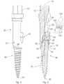
- shows a side elevation of an overdenture retention implant according to this invention;
- Figure 2
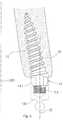
- shows a side elevation of the fixture mount of an implant installation apparatus according to the invention;
- Figure 3
- shows a side elevation of the anchoring device of the implant installation apparatus;
- Figure 4
- shows a side elevation of the overdenture retention implant and installation apparatus in operative combination;
- Figure 5
- shows a cross-sectional view of the combination seen in
Figure 4 , and also illustrates an overdenture retention member; and - Figure 6
- diagrammatically illustrates the implant installed in an upper jaw bone.
- The
implant 10 seen in the drawings has an externally threadedimplant body 12. Thebody 12 has a proximal end 12.1 and a distal end 12.2. The body extends at its proximal end 12.1 from animplant end structure 14 that includes a tool engagement portion 14.1 of hexagonal cross-section and an externally threaded boss 14.2. Thebody 12 andend structure 14 are typically machined in one piece from a suitable grade of titanium or ceramic. - The
implant body 12 has acentral axis 20. Theimplant end structure 14 has acentral axis 22 which is common to the tool engagement portion 14.1 and the boss 14.2. Theaxes inclination 24, and intersect at apoint 26. More is said subsequently about theangle 24. - The
implant end structure 14 also includes a circumscribing shoulder 14.3 between the tool engagement portion 14.1 and theimplant body 12. The shoulder lies in aplane 28 normal to thecentral axis 22 of the implant end structure. Figure 2 illustrates afixture mount 30 forming part of an implant installation apparatus according to the invention.- Referring also to
Figures 4 and 5 , the fixture mount has a partially hollowfirst end 32 bounded by awall 34 terminating at anedge 36. Externally, thewall 34 has a roundcylindrical surface 38. Internally, thewall 34 defines afixture mount socket 40 with a hexagonal cross-section complemental to the hexagonal cross-section of the tool engagement portion 14.1 of the implant end structure. Thesocket 40 has acentral axis 42 inclined at anacute angle 44 relative to acentral axis 46 of the fixture mount. Theangle 44 is the same as theangle 24. - The fixture mount includes an inclined passage or
recess 48 which is part-circular in cross-section. The recess is axially aligned with and leads to thesocket 40 as illustrated inFigure 5 . The fixture mount includes anarrow shoulder 50 which circumscribes an end of thesocket 40. - An opposite,
second end 52 of the fixture mount is non-round in cross-section so as to be engagable in a rotation transmitting manner by a suitable tool (not shown). In the illustrated case, theend 52 has a hexagonal cross-section and is suitable for engagement by, for example, a spanner. - A further component of the installation apparatus is an anchoring device in the form of a locking
cap 60 which has an internally threadedcap socket 62 at one end and atool engagement socket 64 at the opposite end. The thread of thecap socket 62 is complemental to the thread on the boss 14.2 of theimplant end structure 14. The tool-engagement socket 64 has a non-round cross-section, in the illustrated case a hexagonal cross-section, enabling it to be engaged in a rotation-transmitting manner by a cap engaging tool (not shown). - Referring to
Figure 6 , theimplant 10 is installed in use in a hole drilled, reamed or otherwise formed in ajaw bone 70 of an edentulous person who is to be fitted with an overdenture. This is achieved by screwing theimplant body 12 tightly into the hole. Thefixture mount 30 andcap 60 are used in this process. - The fixture mount is moved towards the proximal end of the
implant 10 such that thesocket 40 passes over the threaded boss 14.2 and onto the tool-engagement portion 14.1 as seen inFigure 5 . With thesocket 40 fully received on the tool-engagement portion 14.1, the mouth of the socket seats complementally on the shoulder 14.3 of the implant end structure. It will be understood that for this to happen, the mouth of the socket lies in a plane 72 (Figure 2 ) which is normal to thecentral axis 42 of thesocket 40. - The
cap 60 is then moved along thepassage 48 such that the boss 14.2 is received in thecap socket 62. The cap engaging tool mentioned above is now engaged with thecap socket 64 and is used to screw the cap onto the boss. - When tight, the mouth of the
socket 62 bears on theinternal shoulder 50 of the fixture mount. This prevents thesocket 40 from being detached from the tool-engagement portion 14.1 of the implant end structure, so the fixture mount is effectively locked or anchored on the implant, forming theassembly 80 seen inFigures 4 and 5 . - With the angular relationships described above, the
central axis 20 of theimplant body 12 is aligned and coaxial with thecentral axis 46 of thefixture mount 30. Theaxes - The assembly can now be taken to the patient's mouth where the
distal tip 90 of theimplant body 12 is inserted into the preformed hole in the jaw bone. The spanner or other tool mentioned above can now be engaged with theend 52 of the fixture mount. Manipulation of the tool to rotate the fixture mount in the appropriate sense is transmitted to the implant such that theimplant body 12 is screwed into the hole. - When the
implant body 12 has been tightly screwed into the hole, the tool is disengaged from the fixture mount and the lockingcap 60 is unscrewed from the boss 14.2, allowing thefixture mount 30 to be detached from theimplant body 10. - An
overdenture retention cap 100 can now be screwed onto the boss 14.2. Theretention cap 100 may be entirely conventional and, in the illustrated case, has a threadedsocket 102 to be screwed onto the boss 14.2 and anenlarged head 104, possibly of elliptical shape, onto which the overdenture itself (not shown) can be engaged, for example by a clipping action. - An advantage of the
implant 10 described above is the fact that thecentral axis 22 of the threaded boss is inclined relative to thecentral axis 20 of theimplant body 12 at theangle 24. The importance of this is described with reference toFigure 6 which diagrammatically illustrates theimplant retention cap 100 installed in anupper jaw bone 70. As usual, lateral regions of the jaw bone are themselves inclined relative to amedian plane 200 of the mouth. Theangle 24 is selected such that with theimplant body 12 screwed into a hole which is formed straight into the jaw bone following the inclination of the jaw bone, the boss 14.2, and hence theoverdenture retention cap 100 can be generally aligned with themedian plane 200, i.e. can be generally vertical. This in turn enables the overdenture itself to be properly oriented in an aesthetically pleasing manner. - It will accordingly be understood that the
angle 24 is selected to be similar to the acute angle which the lateral regions of the upper jaw bone make with themedian plane 200. In the illustrated example, theangle 24 is typically in the range 8° to 24° and may, for example, be 12°, corresponding to a normal inclination of an upper jaw bone relative to the median plane. - The installation of the
inclined implant 10 is considerably facilitated by the use of the installation apparatus consisting of thefixture mount 30 and lockingcap 60. - It will be understood that this apparatus makes it possible for the implant body and fixture mount to have aligned axes when assembled together, thereby enabling a conventional tool to be used to screw the
implant body 12 into the bone.
Claims (5)
- In combination, an overdenture retention implant (10) and an installation apparatus for installing the implant, wherein the implant comprises:- an elongate, externally threaded implant body (12) to be screwed into a hole formed in a jawbone (70), the body having a central axis (20); and- an implant end structure (14) at a proximal end (12.1) of the implant body, the implant end structure including a tool engagement portion (14.1) and a threaded boss (14.2) to be engaged in threaded manner by an overdenture retention cap (100) configured for attachment thereto of an overdenture,wherein the tool engagement portion (14.1) and the boss (14.2) have a common, central axis which intersects the central axis of the implant body at an acute angle to that central axis,
and wherein the installation apparatus comprises:- a fixture mount (30) having a hollow first end (32) defining a fixture mount socket (40) shaped to engage in rotationally fast manner with the tool engagement portion of the implant end structure of the implant for the purposes of rotating the implant to screw the body into the hole in the jawbone and an opposite second end (52) engagable in rotationally fast manner by a rotation tool which can be manipulated to rotate the fixture mount and hence an implant engaged thereby; and- an anchoring device for releasably anchoring the fixture mount in engagement with the implant, with the central axis of the implant body aligned and coaxial with a central axis (46) of the fixture mount, while the fixture mount and implant are rotated;characterized in that:- the fixture mount socket (40) has a central axis (42) inclined relative to the central axis (46) of the fixture mount (30) by an angle (44) which is the same as the angle (24) by which the implant end structure (14) is inclined relative to the central axis (20) of the implant body (12);- a mouth of the fixture mount socket lies in a plane (72) normal to the central axis of the fixture mount socket; and- the fixture mount socket includes an internal shoulder (50) and the anchoring device comprises a cap (60) which has a threaded cap socket (62) for threaded engagement with the boss (14.2) of the implant end structure of the implant (10), a mouth of the cap socket being arranged to abut the internal shoulder of the fixture mount socket when the cap socket is threaded onto the boss, thereby to anchor the fixture mount in engagement with the tool engagement portion of the implant end structure of the implant. - A combination according to claim 1 wherein the acute angular inclination (24) of the axis (22) of the end structure (14) of the implant (10) relative to the axis (20) of the body (12) of the implant is in the range 8° to 24°.
- A combination according to claim 2 wherein the acute angular inclination of the axis of the end structure relative to the axis of the body is approximately 12°.
- A combination according to any one of the preceding claims wherein the mouth of the fixture mount socket (40) bears on an external shoulder (14.3) of the implant (10) when the mouth of the cap socket (62) abuts the internal shoulder (50) of the fixture mount.
- A combination according to any one of the preceding claims wherein the cap (60) has a tool engagement socket (64) at an end thereof opposite to the cap socket (62).
Applications Claiming Priority (2)
| Application Number | Priority Date | Filing Date | Title |
|---|---|---|---|
| ZA201405274 | 2014-07-17 | ||
| PCT/IB2015/055278WO2016009320A2 (en) | 2014-07-17 | 2015-07-13 | Overdenture retention implant and apparatus for installing it |
Publications (2)
| Publication Number | Publication Date |
|---|---|
| EP3169267A2 EP3169267A2 (en) | 2017-05-24 |
| EP3169267B1true EP3169267B1 (en) | 2018-12-19 |
Family
ID=54015132
Family Applications (1)
| Application Number | Title | Priority Date | Filing Date |
|---|---|---|---|
| EP15756988.0ANot-in-forceEP3169267B1 (en) | 2014-07-17 | 2015-07-13 | Overdenture retention implant |
Country Status (3)
| Country | Link |
|---|---|
| US (1) | US20170252130A1 (en) |
| EP (1) | EP3169267B1 (en) |
| WO (1) | WO2016009320A2 (en) |
Families Citing this family (5)
| Publication number | Priority date | Publication date | Assignee | Title |
|---|---|---|---|---|
| EP3106121A1 (en) | 2015-06-19 | 2016-12-21 | Nobel Biocare Services AG | Placement device for a dental component |
| IT201600068763A1 (en)* | 2016-07-01 | 2018-01-01 | Errecieffe S R L | TOOL SET WITH MONOPHASIC DENTAL SYSTEMS WITH INCLINED AXIS |
| KR102462085B1 (en)* | 2018-02-21 | 2022-11-01 | 사우던 임플란츠 (피티와이) 리미티드 | Dental implants of asymmetric cheekbones with partial micro-threads/grooves |
| US20240122684A1 (en)* | 2022-10-13 | 2024-04-18 | Tomer TSOHABANY | Dental abutment guide rod and method |
| EP4523651A1 (en)* | 2023-09-14 | 2025-03-19 | H.D.C. S.r.l. | Medical device, medical kit and kit for orthodontic treatments |
Family Cites Families (27)
| Publication number | Priority date | Publication date | Assignee | Title |
|---|---|---|---|---|
| US5209666A (en)* | 1990-05-15 | 1993-05-11 | Calcitek, Inc. | Endosseous implant system wtih captured screw |
| US5135395A (en)* | 1990-07-05 | 1992-08-04 | Marlin Gerald M | Implant collar and post system |
| SE502433C2 (en)* | 1994-02-11 | 1995-10-16 | Nobelpharma Ab | Spacer for dental implants |
| DE19635619A1 (en)* | 1996-09-03 | 1998-03-05 | Peter Velten | Implant systems as well as methods and tools for implanting in the edentulous jaw |
| SE513778C2 (en)* | 1999-03-18 | 2000-11-06 | Nobel Biocare Ab | Method, arrangement and use for application of spacer to implant by screw. |
| US6416324B1 (en)* | 1999-12-10 | 2002-07-09 | Sulzer Dental Inc. | One step dental implant delivery system |
| SE516040C2 (en)* | 2000-03-23 | 2001-11-12 | Nobel Biocare Ab | Arrangement including spacer for implants and such spacer and screwdriver for spacer attachment |
| US6454567B1 (en)* | 2001-04-23 | 2002-09-24 | Ace Surgical Supply Co., Inc. | Dental implant delivery and drive tool |
| US7264469B2 (en)* | 2001-08-10 | 2007-09-04 | Juan Carlos Abarno | Split-implant and abutment system for dental reconstruction |
| IL158789A (en)* | 2002-11-13 | 2009-11-18 | Biomet 3I Llc | Dental implant system |
| US20040127909A1 (en)* | 2002-12-16 | 2004-07-01 | Morgan Vincent J. | Threaded dental or medical implants |
| DE102005005402B4 (en)* | 2005-02-05 | 2011-02-17 | Friadent Gmbh | Dental implant and implant system |
| US8506296B2 (en)* | 2005-06-17 | 2013-08-13 | Zimmer Dental, Inc. | Dental restorative system and components |
| US8430668B2 (en)* | 2005-06-17 | 2013-04-30 | Zimmer Dental, Inc. | Dental restorative system and components |
| ES2315060B1 (en)* | 2005-10-10 | 2009-12-09 | Vicente Gabriel Faus Badia | IMPLANTOLOGICAL PROTECTED ANGLE AND METHOD FOR USE. |
| US8771285B2 (en)* | 2006-09-15 | 2014-07-08 | Zimmer Dental, Inc. | Drive tool for orthopedic screws |
| US8192199B2 (en)* | 2006-11-15 | 2012-06-05 | Uri Arni | Dental implant for implanting an artificial tooth on the anterior portion of the mandible of a patient |
| WO2008138644A1 (en)* | 2007-05-16 | 2008-11-20 | Nobel Biocare Services Ag | Ceramic one-piece dental implant |
| US8142193B2 (en)* | 2009-06-25 | 2012-03-27 | Bar Shalom Eliezer | Compound angular joint for connecting an abutment to a dental implant in a predefined angle |
| JP5285021B2 (en)* | 2009-09-02 | 2013-09-11 | 株式会社アルツロ | Human implant structure |
| JP6033776B2 (en)* | 2010-09-24 | 2016-11-30 | ジンマー デンタル,インコーポレイティド | Dental implant and abutment system |
| EP2444023A1 (en)* | 2010-10-20 | 2012-04-25 | Astra Tech AB | A dental component, a dental fixture, a dental implant assembly and a dental implant system |
| DE102011012212A1 (en)* | 2011-02-23 | 2012-08-23 | Marcus Abboud | Dental jaw implant for wearing dentures |
| EP2732791B1 (en)* | 2011-07-11 | 2019-03-06 | Neobiotech Co., Ltd. | Angular friction joint type of dental implant |
| GB2509136A (en)* | 2012-12-21 | 2014-06-25 | Nobel Biocare Services Ag | Dental component with metal adapter |
| ES1078459Y (en)* | 2012-12-26 | 2013-04-22 | Montalban Joaquin Rovello | METAL PILLAR FOR DENTAL IMPLANTS |
| IL263449B (en)* | 2016-06-14 | 2022-09-01 | Southern Implants Pty Ltd | Main body dental implant with reverse taper for anterior sockets after extraction |
- 2015
- 2015-07-13EPEP15756988.0Apatent/EP3169267B1/ennot_activeNot-in-force
- 2015-07-13WOPCT/IB2015/055278patent/WO2016009320A2/enactiveApplication Filing
- 2015-07-13USUS15/326,919patent/US20170252130A1/ennot_activeAbandoned
Non-Patent Citations (1)
| Title |
|---|
| None* |
Also Published As
| Publication number | Publication date |
|---|---|
| WO2016009320A2 (en) | 2016-01-21 |
| US20170252130A1 (en) | 2017-09-07 |
| WO2016009320A9 (en) | 2016-07-07 |
| WO2016009320A3 (en) | 2016-03-17 |
| EP3169267A2 (en) | 2017-05-24 |
Similar Documents
| Publication | Publication Date | Title |
|---|---|---|
| EP3169267B1 (en) | Overdenture retention implant | |
| US9314318B2 (en) | Dental anchor apparatus and method | |
| US6287115B1 (en) | Dental implant and tool and method for effecting a dental restoration using the same | |
| US20070059666A1 (en) | Dental implant system | |
| CA2672363C (en) | Arrangement for insertion of implants | |
| US9095397B2 (en) | Arrangement for insertion of implants | |
| EP2868291A1 (en) | Dental implant | |
| KR102730608B1 (en) | Implant system | |
| US20080145819A1 (en) | Screw-in Enossal Dental Implant | |
| US20090291412A1 (en) | Dental implant, abutment structure and method for implanting a dental implant | |
| WO2013186764A1 (en) | Triple lock abutment system | |
| US9381073B2 (en) | Assembly of a dental implant and a prosthetic element | |
| US10507085B2 (en) | Structure enabling continuous angular adjustment for fixing a single dental device into an implant | |
| CN109963511A (en) | Artificial dental implant system with positive strut screw locking and retrieval mechanism | |
| US7293991B1 (en) | Dental implant with the fixture intermediate support | |
| CN106901848B (en) | Anchorage nail | |
| JP2005270334A (en) | Dental implant | |
| KR101134343B1 (en) | Removal driver for post screw to remove post screw | |
| JP2015146927A (en) | dental implant | |
| US9345560B2 (en) | Metal pillar for dental implants | |
| EP3372190B1 (en) | Unit comprising a dental implant and prosthetic components, including a transepithelial sleeve with an anti-rotational upper connection | |
| JP5820767B2 (en) | Jig for removing dental abutment from implant fixture | |
| EP3659544B1 (en) | Dental implants | |
| KR20140141462A (en) | An abutment enable for accuracy insertion and implant including such abutment | |
| KR20160027493A (en) | Implant apparatus |
Legal Events
| Date | Code | Title | Description |
|---|---|---|---|
| STAA | Information on the status of an ep patent application or granted ep patent | Free format text:STATUS: THE INTERNATIONAL PUBLICATION HAS BEEN MADE | |
| PUAI | Public reference made under article 153(3) epc to a published international application that has entered the european phase | Free format text:ORIGINAL CODE: 0009012 | |
| STAA | Information on the status of an ep patent application or granted ep patent | Free format text:STATUS: REQUEST FOR EXAMINATION WAS MADE | |
| 17P | Request for examination filed | Effective date:20170206 | |
| AK | Designated contracting states | Kind code of ref document:A2 Designated state(s):AL AT BE BG CH CY CZ DE DK EE ES FI FR GB GR HR HU IE IS IT LI LT LU LV MC MK MT NL NO PL PT RO RS SE SI SK SM TR | |
| AX | Request for extension of the european patent | Extension state:BA ME | |
| DAV | Request for validation of the european patent (deleted) | ||
| DAX | Request for extension of the european patent (deleted) | ||
| GRAP | Despatch of communication of intention to grant a patent | Free format text:ORIGINAL CODE: EPIDOSNIGR1 | |
| STAA | Information on the status of an ep patent application or granted ep patent | Free format text:STATUS: GRANT OF PATENT IS INTENDED | |
| INTG | Intention to grant announced | Effective date:20180628 | |
| GRAS | Grant fee paid | Free format text:ORIGINAL CODE: EPIDOSNIGR3 | |
| GRAA | (expected) grant | Free format text:ORIGINAL CODE: 0009210 | |
| STAA | Information on the status of an ep patent application or granted ep patent | Free format text:STATUS: THE PATENT HAS BEEN GRANTED | |
| AK | Designated contracting states | Kind code of ref document:B1 Designated state(s):AL AT BE BG CH CY CZ DE DK EE ES FI FR GB GR HR HU IE IS IT LI LT LU LV MC MK MT NL NO PL PT RO RS SE SI SK SM TR | |
| REG | Reference to a national code | Ref country code:GB Ref legal event code:FG4D | |
| REG | Reference to a national code | Ref country code:CH Ref legal event code:EP | |
| REG | Reference to a national code | Ref country code:IE Ref legal event code:FG4D | |
| REG | Reference to a national code | Ref country code:DE Ref legal event code:R096 Ref document number:602015021925 Country of ref document:DE | |
| REG | Reference to a national code | Ref country code:AT Ref legal event code:REF Ref document number:1077861 Country of ref document:AT Kind code of ref document:T Effective date:20190115 | |
| REG | Reference to a national code | Ref country code:NL Ref legal event code:MP Effective date:20181219 | |
| PG25 | Lapsed in a contracting state [announced via postgrant information from national office to epo] | Ref country code:LV Free format text:LAPSE BECAUSE OF FAILURE TO SUBMIT A TRANSLATION OF THE DESCRIPTION OR TO PAY THE FEE WITHIN THE PRESCRIBED TIME-LIMIT Effective date:20181219 Ref country code:HR Free format text:LAPSE BECAUSE OF FAILURE TO SUBMIT A TRANSLATION OF THE DESCRIPTION OR TO PAY THE FEE WITHIN THE PRESCRIBED TIME-LIMIT Effective date:20181219 Ref country code:BG Free format text:LAPSE BECAUSE OF FAILURE TO SUBMIT A TRANSLATION OF THE DESCRIPTION OR TO PAY THE FEE WITHIN THE PRESCRIBED TIME-LIMIT Effective date:20190319 Ref country code:NO Free format text:LAPSE BECAUSE OF FAILURE TO SUBMIT A TRANSLATION OF THE DESCRIPTION OR TO PAY THE FEE WITHIN THE PRESCRIBED TIME-LIMIT Effective date:20190319 Ref country code:LT Free format text:LAPSE BECAUSE OF FAILURE TO SUBMIT A TRANSLATION OF THE DESCRIPTION OR TO PAY THE FEE WITHIN THE PRESCRIBED TIME-LIMIT Effective date:20181219 Ref country code:FI Free format text:LAPSE BECAUSE OF FAILURE TO SUBMIT A TRANSLATION OF THE DESCRIPTION OR TO PAY THE FEE WITHIN THE PRESCRIBED TIME-LIMIT Effective date:20181219 | |
| REG | Reference to a national code | Ref country code:LT Ref legal event code:MG4D | |
| REG | Reference to a national code | Ref country code:AT Ref legal event code:MK05 Ref document number:1077861 Country of ref document:AT Kind code of ref document:T Effective date:20181219 | |
| PG25 | Lapsed in a contracting state [announced via postgrant information from national office to epo] | Ref country code:SE Free format text:LAPSE BECAUSE OF FAILURE TO SUBMIT A TRANSLATION OF THE DESCRIPTION OR TO PAY THE FEE WITHIN THE PRESCRIBED TIME-LIMIT Effective date:20181219 Ref country code:RS Free format text:LAPSE BECAUSE OF FAILURE TO SUBMIT A TRANSLATION OF THE DESCRIPTION OR TO PAY THE FEE WITHIN THE PRESCRIBED TIME-LIMIT Effective date:20181219 Ref country code:AL Free format text:LAPSE BECAUSE OF FAILURE TO SUBMIT A TRANSLATION OF THE DESCRIPTION OR TO PAY THE FEE WITHIN THE PRESCRIBED TIME-LIMIT Effective date:20181219 Ref country code:GR Free format text:LAPSE BECAUSE OF FAILURE TO SUBMIT A TRANSLATION OF THE DESCRIPTION OR TO PAY THE FEE WITHIN THE PRESCRIBED TIME-LIMIT Effective date:20190320 | |
| PG25 | Lapsed in a contracting state [announced via postgrant information from national office to epo] | Ref country code:NL Free format text:LAPSE BECAUSE OF FAILURE TO SUBMIT A TRANSLATION OF THE DESCRIPTION OR TO PAY THE FEE WITHIN THE PRESCRIBED TIME-LIMIT Effective date:20181219 | |
| PG25 | Lapsed in a contracting state [announced via postgrant information from national office to epo] | Ref country code:CZ Free format text:LAPSE BECAUSE OF FAILURE TO SUBMIT A TRANSLATION OF THE DESCRIPTION OR TO PAY THE FEE WITHIN THE PRESCRIBED TIME-LIMIT Effective date:20181219 Ref country code:IT Free format text:LAPSE BECAUSE OF FAILURE TO SUBMIT A TRANSLATION OF THE DESCRIPTION OR TO PAY THE FEE WITHIN THE PRESCRIBED TIME-LIMIT Effective date:20181219 Ref country code:PT Free format text:LAPSE BECAUSE OF FAILURE TO SUBMIT A TRANSLATION OF THE DESCRIPTION OR TO PAY THE FEE WITHIN THE PRESCRIBED TIME-LIMIT Effective date:20190419 Ref country code:PL Free format text:LAPSE BECAUSE OF FAILURE TO SUBMIT A TRANSLATION OF THE DESCRIPTION OR TO PAY THE FEE WITHIN THE PRESCRIBED TIME-LIMIT Effective date:20181219 Ref country code:ES Free format text:LAPSE BECAUSE OF FAILURE TO SUBMIT A TRANSLATION OF THE DESCRIPTION OR TO PAY THE FEE WITHIN THE PRESCRIBED TIME-LIMIT Effective date:20181219 | |
| PG25 | Lapsed in a contracting state [announced via postgrant information from national office to epo] | Ref country code:RO Free format text:LAPSE BECAUSE OF FAILURE TO SUBMIT A TRANSLATION OF THE DESCRIPTION OR TO PAY THE FEE WITHIN THE PRESCRIBED TIME-LIMIT Effective date:20181219 Ref country code:IS Free format text:LAPSE BECAUSE OF FAILURE TO SUBMIT A TRANSLATION OF THE DESCRIPTION OR TO PAY THE FEE WITHIN THE PRESCRIBED TIME-LIMIT Effective date:20190419 Ref country code:SK Free format text:LAPSE BECAUSE OF FAILURE TO SUBMIT A TRANSLATION OF THE DESCRIPTION OR TO PAY THE FEE WITHIN THE PRESCRIBED TIME-LIMIT Effective date:20181219 Ref country code:EE Free format text:LAPSE BECAUSE OF FAILURE TO SUBMIT A TRANSLATION OF THE DESCRIPTION OR TO PAY THE FEE WITHIN THE PRESCRIBED TIME-LIMIT Effective date:20181219 Ref country code:SM Free format text:LAPSE BECAUSE OF FAILURE TO SUBMIT A TRANSLATION OF THE DESCRIPTION OR TO PAY THE FEE WITHIN THE PRESCRIBED TIME-LIMIT Effective date:20181219 | |
| REG | Reference to a national code | Ref country code:DE Ref legal event code:R097 Ref document number:602015021925 Country of ref document:DE | |
| PLBE | No opposition filed within time limit | Free format text:ORIGINAL CODE: 0009261 | |
| STAA | Information on the status of an ep patent application or granted ep patent | Free format text:STATUS: NO OPPOSITION FILED WITHIN TIME LIMIT | |
| PG25 | Lapsed in a contracting state [announced via postgrant information from national office to epo] | Ref country code:AT Free format text:LAPSE BECAUSE OF FAILURE TO SUBMIT A TRANSLATION OF THE DESCRIPTION OR TO PAY THE FEE WITHIN THE PRESCRIBED TIME-LIMIT Effective date:20181219 Ref country code:DK Free format text:LAPSE BECAUSE OF FAILURE TO SUBMIT A TRANSLATION OF THE DESCRIPTION OR TO PAY THE FEE WITHIN THE PRESCRIBED TIME-LIMIT Effective date:20181219 | |
| 26N | No opposition filed | Effective date:20190920 | |
| REG | Reference to a national code | Ref country code:DE Ref legal event code:R119 Ref document number:602015021925 Country of ref document:DE | |
| PG25 | Lapsed in a contracting state [announced via postgrant information from national office to epo] | Ref country code:SI Free format text:LAPSE BECAUSE OF FAILURE TO SUBMIT A TRANSLATION OF THE DESCRIPTION OR TO PAY THE FEE WITHIN THE PRESCRIBED TIME-LIMIT Effective date:20181219 Ref country code:MC Free format text:LAPSE BECAUSE OF FAILURE TO SUBMIT A TRANSLATION OF THE DESCRIPTION OR TO PAY THE FEE WITHIN THE PRESCRIBED TIME-LIMIT Effective date:20181219 | |
| REG | Reference to a national code | Ref country code:CH Ref legal event code:PL | |
| GBPC | Gb: european patent ceased through non-payment of renewal fee | Effective date:20190713 | |
| PG25 | Lapsed in a contracting state [announced via postgrant information from national office to epo] | Ref country code:TR Free format text:LAPSE BECAUSE OF FAILURE TO SUBMIT A TRANSLATION OF THE DESCRIPTION OR TO PAY THE FEE WITHIN THE PRESCRIBED TIME-LIMIT Effective date:20181219 | |
| REG | Reference to a national code | Ref country code:BE Ref legal event code:MM Effective date:20190731 | |
| PG25 | Lapsed in a contracting state [announced via postgrant information from national office to epo] | Ref country code:GB Free format text:LAPSE BECAUSE OF NON-PAYMENT OF DUE FEES Effective date:20190713 Ref country code:DE Free format text:LAPSE BECAUSE OF NON-PAYMENT OF DUE FEES Effective date:20200201 | |
| PG25 | Lapsed in a contracting state [announced via postgrant information from national office to epo] | Ref country code:LU Free format text:LAPSE BECAUSE OF NON-PAYMENT OF DUE FEES Effective date:20190713 Ref country code:CH Free format text:LAPSE BECAUSE OF NON-PAYMENT OF DUE FEES Effective date:20190731 Ref country code:LI Free format text:LAPSE BECAUSE OF NON-PAYMENT OF DUE FEES Effective date:20190731 Ref country code:BE Free format text:LAPSE BECAUSE OF NON-PAYMENT OF DUE FEES Effective date:20190731 | |
| PG25 | Lapsed in a contracting state [announced via postgrant information from national office to epo] | Ref country code:FR Free format text:LAPSE BECAUSE OF NON-PAYMENT OF DUE FEES Effective date:20190731 | |
| PG25 | Lapsed in a contracting state [announced via postgrant information from national office to epo] | Ref country code:IE Free format text:LAPSE BECAUSE OF NON-PAYMENT OF DUE FEES Effective date:20190713 | |
| PG25 | Lapsed in a contracting state [announced via postgrant information from national office to epo] | Ref country code:CY Free format text:LAPSE BECAUSE OF FAILURE TO SUBMIT A TRANSLATION OF THE DESCRIPTION OR TO PAY THE FEE WITHIN THE PRESCRIBED TIME-LIMIT Effective date:20181219 | |
| PG25 | Lapsed in a contracting state [announced via postgrant information from national office to epo] | Ref country code:MT Free format text:LAPSE BECAUSE OF FAILURE TO SUBMIT A TRANSLATION OF THE DESCRIPTION OR TO PAY THE FEE WITHIN THE PRESCRIBED TIME-LIMIT Effective date:20181219 Ref country code:HU Free format text:LAPSE BECAUSE OF FAILURE TO SUBMIT A TRANSLATION OF THE DESCRIPTION OR TO PAY THE FEE WITHIN THE PRESCRIBED TIME-LIMIT; INVALID AB INITIO Effective date:20150713 | |
| PG25 | Lapsed in a contracting state [announced via postgrant information from national office to epo] | Ref country code:MK Free format text:LAPSE BECAUSE OF FAILURE TO SUBMIT A TRANSLATION OF THE DESCRIPTION OR TO PAY THE FEE WITHIN THE PRESCRIBED TIME-LIMIT Effective date:20181219 |