EP3169081B1 - Wireless earbuds and related methods - Google Patents
Wireless earbuds and related methodsDownload PDFInfo
- Publication number
- EP3169081B1 EP3169081B1EP16197949.7AEP16197949AEP3169081B1EP 3169081 B1EP3169081 B1EP 3169081B1EP 16197949 AEP16197949 AEP 16197949AEP 3169081 B1EP3169081 B1EP 3169081B1
- Authority
- EP
- European Patent Office
- Prior art keywords
- earbud
- wireless
- assembly
- tether
- control unit
- Prior art date
- Legal status (The legal status is an assumption and is not a legal conclusion. Google has not performed a legal analysis and makes no representation as to the accuracy of the status listed.)
- Active
Links
Images


Classifications
- H—ELECTRICITY
- H04—ELECTRIC COMMUNICATION TECHNIQUE
- H04R—LOUDSPEAKERS, MICROPHONES, GRAMOPHONE PICK-UPS OR LIKE ACOUSTIC ELECTROMECHANICAL TRANSDUCERS; DEAF-AID SETS; PUBLIC ADDRESS SYSTEMS
- H04R1/00—Details of transducers, loudspeakers or microphones
- H04R1/10—Earpieces; Attachments therefor ; Earphones; Monophonic headphones
- H04R1/1041—Mechanical or electronic switches, or control elements
- H—ELECTRICITY
- H04—ELECTRIC COMMUNICATION TECHNIQUE
- H04R—LOUDSPEAKERS, MICROPHONES, GRAMOPHONE PICK-UPS OR LIKE ACOUSTIC ELECTROMECHANICAL TRANSDUCERS; DEAF-AID SETS; PUBLIC ADDRESS SYSTEMS
- H04R1/00—Details of transducers, loudspeakers or microphones
- H04R1/10—Earpieces; Attachments therefor ; Earphones; Monophonic headphones
- H04R1/1091—Details not provided for in groups H04R1/1008 - H04R1/1083
- A—HUMAN NECESSITIES
- A61—MEDICAL OR VETERINARY SCIENCE; HYGIENE
- A61B—DIAGNOSIS; SURGERY; IDENTIFICATION
- A61B5/00—Measuring for diagnostic purposes; Identification of persons
- A61B5/0002—Remote monitoring of patients using telemetry, e.g. transmission of vital signals via a communication network
- A61B5/0015—Remote monitoring of patients using telemetry, e.g. transmission of vital signals via a communication network characterised by features of the telemetry system
- A—HUMAN NECESSITIES
- A61—MEDICAL OR VETERINARY SCIENCE; HYGIENE
- A61B—DIAGNOSIS; SURGERY; IDENTIFICATION
- A61B5/00—Measuring for diagnostic purposes; Identification of persons
- A61B5/48—Other medical applications
- A61B5/486—Biofeedback
- A—HUMAN NECESSITIES
- A61—MEDICAL OR VETERINARY SCIENCE; HYGIENE
- A61B—DIAGNOSIS; SURGERY; IDENTIFICATION
- A61B5/00—Measuring for diagnostic purposes; Identification of persons
- A61B5/68—Arrangements of detecting, measuring or recording means, e.g. sensors, in relation to patient
- A61B5/6801—Arrangements of detecting, measuring or recording means, e.g. sensors, in relation to patient specially adapted to be attached to or worn on the body surface
- A61B5/6802—Sensor mounted on worn items
- A61B5/6803—Head-worn items, e.g. helmets, masks, headphones or goggles
- H—ELECTRICITY
- H04—ELECTRIC COMMUNICATION TECHNIQUE
- H04R—LOUDSPEAKERS, MICROPHONES, GRAMOPHONE PICK-UPS OR LIKE ACOUSTIC ELECTROMECHANICAL TRANSDUCERS; DEAF-AID SETS; PUBLIC ADDRESS SYSTEMS
- H04R1/00—Details of transducers, loudspeakers or microphones
- H04R1/10—Earpieces; Attachments therefor ; Earphones; Monophonic headphones
- H04R1/1016—Earpieces of the intra-aural type
- H—ELECTRICITY
- H04—ELECTRIC COMMUNICATION TECHNIQUE
- H04R—LOUDSPEAKERS, MICROPHONES, GRAMOPHONE PICK-UPS OR LIKE ACOUSTIC ELECTROMECHANICAL TRANSDUCERS; DEAF-AID SETS; PUBLIC ADDRESS SYSTEMS
- H04R1/00—Details of transducers, loudspeakers or microphones
- H04R1/10—Earpieces; Attachments therefor ; Earphones; Monophonic headphones
- H04R1/1025—Accumulators or arrangements for charging
- H—ELECTRICITY
- H04—ELECTRIC COMMUNICATION TECHNIQUE
- H04R—LOUDSPEAKERS, MICROPHONES, GRAMOPHONE PICK-UPS OR LIKE ACOUSTIC ELECTROMECHANICAL TRANSDUCERS; DEAF-AID SETS; PUBLIC ADDRESS SYSTEMS
- H04R1/00—Details of transducers, loudspeakers or microphones
- H04R1/10—Earpieces; Attachments therefor ; Earphones; Monophonic headphones
- H04R1/1033—Cables or cables storage, e.g. cable reels
- H—ELECTRICITY
- H04—ELECTRIC COMMUNICATION TECHNIQUE
- H04R—LOUDSPEAKERS, MICROPHONES, GRAMOPHONE PICK-UPS OR LIKE ACOUSTIC ELECTROMECHANICAL TRANSDUCERS; DEAF-AID SETS; PUBLIC ADDRESS SYSTEMS
- H04R1/00—Details of transducers, loudspeakers or microphones
- H04R1/10—Earpieces; Attachments therefor ; Earphones; Monophonic headphones
- H04R1/1058—Manufacture or assembly
- H—ELECTRICITY
- H04—ELECTRIC COMMUNICATION TECHNIQUE
- H04R—LOUDSPEAKERS, MICROPHONES, GRAMOPHONE PICK-UPS OR LIKE ACOUSTIC ELECTROMECHANICAL TRANSDUCERS; DEAF-AID SETS; PUBLIC ADDRESS SYSTEMS
- H04R2201/00—Details of transducers, loudspeakers or microphones covered by H04R1/00 but not provided for in any of its subgroups
- H04R2201/10—Details of earpieces, attachments therefor, earphones or monophonic headphones covered by H04R1/10 but not provided for in any of its subgroups
- H—ELECTRICITY
- H04—ELECTRIC COMMUNICATION TECHNIQUE
- H04R—LOUDSPEAKERS, MICROPHONES, GRAMOPHONE PICK-UPS OR LIKE ACOUSTIC ELECTROMECHANICAL TRANSDUCERS; DEAF-AID SETS; PUBLIC ADDRESS SYSTEMS
- H04R2420/00—Details of connection covered by H04R, not provided for in its groups
- H04R2420/05—Detection of connection of loudspeakers or headphones to amplifiers
- H—ELECTRICITY
- H04—ELECTRIC COMMUNICATION TECHNIQUE
- H04R—LOUDSPEAKERS, MICROPHONES, GRAMOPHONE PICK-UPS OR LIKE ACOUSTIC ELECTROMECHANICAL TRANSDUCERS; DEAF-AID SETS; PUBLIC ADDRESS SYSTEMS
- H04R2420/00—Details of connection covered by H04R, not provided for in its groups
- H04R2420/07—Applications of wireless loudspeakers or wireless microphones
Definitions
- the present disclosurerelates generally to earbud headphones, and more specifically to earbuds configured to receive a wireless data signal from a media device.
- Earbud headphonesare used to convert an electronic signal into an audible sound, which is transmitted to the ear of a person using the earbud headphones.
- Earbud headphonesare used in conjunction with many different types of electronic devices, such as media players, hearing aids, cellular telephones, televisions, computers, etc.
- earbud headphonesare relatively small headphones that rest within the concha of the outer ear and are often referred to as "in-ear” headphones.
- Earbud headphonesare retained in place by the cooperation and mechanical interference between the earbud headphone and the ear of the user.
- Some earbud headphonesinclude a portion that is sized and configured to extend from a main body of the headphone into the external auditory canal of the ear.
- Earbud headphonesare popular among users because they are generally relatively small and portable. Moreover, when a user is participating in various activities, earbud headphones interfere to a much lesser extent with the other accessories or equipment of the user, such as helmets, goggles, hats, and headbands compared to on-ear and over-ear headphones, which often include a headband or other connecting structure (in addition to wiring) extending around the head of the user between each headphone.
- Some earbud headphonesmay include wireless functionality. For example, data from a media player may be transmitted by radio frequency (RF) signals from a media device to a wireless earbud.
- RFradio frequency
- Wireless protocolssuch as Wi-Fi, Bluetooth®, or other protocols may be used for wireless transmission.
- the document US 2015/0230019 A1discloses an electronic wearable device including an electrical cord for carrying electrical signals.
- An electrical power moduleincludes an interface for detachable connection to the electrical cord.
- a first audio moduleincludes an interface for detachable connecting to the electrical cord.
- a second audio moduleincludes an interface for detachable connecting to the electrical cord. The electrical cord is configured to support the first audio module and the second audio module thereon.
- the document US 2005/0136839 A1discloses a modular wireless headset including wearable earpiece(s) and wearable microphone(s), wherein the earpiece and microphone may be physically separate devices.
- the wearable earpiecerenders inbound radio frequencies received from a host device audible.
- the wearable earpiecemay include a receiver module, data recovery module, and speaker module.
- the receiver modulemay convert inbound RF signals into low intermediate frequency (IF) signals.
- the data recovery modulerecovers audio signals from the low IF signals.
- WO 2016/032011 A1discloses a wireless headset including a main body and sub-bodies detachably attached to both lateral ends of the main body by a retractable cable. Earpieces are detachably attached to the sub-bodies and configured to output a sound when supportedly installed in the sub-bodies and a controller is configured to output the sound wirelessly through the earpieces when the earpieces are separated from the sub-bodies.
- the document EP 2 506 597 A1discloses a wireless listening device that can be used in conjunction with a host device to provide an end user a pleasurable listening experience especially during periods of physical activity.
- the host devicecan take the form of a portable media player.
- ear bud headphonesconfigured for use with a portable media player including a main body portion with an extended curvature configuration.
- the ear bud headphonesinclude a speaker housing and an extension that form a gap between the speaker housing and the extension. The user can secure a portion of the user's outer ear in the gap such that the ear bud is securely and comfortably held in place within a user's ear.
- a wireless earbud systemincludes a first earbud assembly and a second earbud assembly.
- Each of the first earbud assembly and the second earbud assemblyincludes a housing, an audio driver disposed within the housing, and a wireless receiving unit operatively coupled to the audio driver.
- the wireless receiving unitis configured to receive a wireless data signal and drive the audio driver based on audio data transmitted in the wireless data signal.
- the wireless earbud systemfurther includes a tether with a first end and a second end.
- the first end of the tetheris configured to removably couple to the first earbud assembly by a first detachable connector
- the second end of the tetheris configured to removably couple to the second earbud assembly by a second detachable connector.
- the tetheralso includes an electronic control unit disposed intermediate the first end of the tether and the second end of the tether.
- a wireless earbud systemin another aspect, includes a first earbud assembly and a second earbud assembly.
- Each of the first earbud assembly and the second earbud assemblyinclude an audio driver, a wireless receiving unit operatively coupled to the audio driver, the wireless receiving unit configured to receive a wireless data signal, and an earbud battery configured to supply power to one or both of the audio driver and the wireless receiving unit.
- the wireless earbud systemalso includes a tether including a first end with a first detachable connector configured to mechanically and electrically couple the first end of the tether to the first earbud assembly, and a second end with a second detachable connector configured to mechanically and electrically couple the second end of the tether to the second earbud assembly.
- the electronic control unitincludes a wireless unit configured to receive a wireless data signal from a media device and to transmit an audio signal based on the wireless data signal through electrical conductors in the tether to the first and second earbud assemblies when the first and second earbud assemblies are coupled to the first and second ends of the tether, respectively, and an electronic control unit battery configured to supply power to the wireless unit.
- a method of forming a wireless earbud systemincludes forming an electronic control unit comprising a wireless unit, a battery, and a tether. The method also includes forming first and second wireless earbud assemblies, and configuring first and second ends of the tether to removably couple to the first and second wireless earbud assemblies.
- the methodalso includes configuring one or both of the first and second wireless earbud assemblies to receive a wireless signal from a media device and to drive audio drivers in the first and second wireless earbud assemblies with an audio signal based on data received from the media device when the first and second ends of the tether are decoupled from the first and second wireless earbud assemblies, and configuring the wireless unit of the electronic control unit to receive a wireless signal from the media device and to drive the audio drivers in the first and second wireless earbud assemblies through electrical conductors disposed within the tether with an audio signal based on data received wirelessly from the media device when the first and second ends of the tether are respectively coupled to the first and second earbud assemblies.
- the disclosurerelates to earbud headphones configured to communicate wirelessly (e.g., through radio frequency (RF) electromagnetic waves) with a media device.
- the earbud headphonesmay include a tether that mechanically and/or electrically couples the earbud headphones to one another.
- the earbud headphonesmay function differently when connected by the tether compared to when the earbud headphones are used without the tether.
- FIG. 1is a plan view of a wireless earbud system 100 according to the disclosure.
- the wireless earbud system 100may include a first earbud 102 and a second earbud 104.
- the first earbud 102 and the second earbud 104may include a first earbud housing 106 and a second earbud housing 108, respectively.
- the wireless earbud system 100includes a tether 110 formed of a lightweight, flexible material, such as a woven fabric cord, a polymer (plastic, elastomeric, etc.) cord, etc.
- the tether 110may include a first end 112 and a second end 113.
- the first end 112 and the second end 113may include detachable connectors 114 and 115, respectively.
- the detachable connectors 114 and 115may be configured to mechanically couple the first end 112 of the tether 110 to the first earbud 102, and the second end 113 of the tether 110 to the second earbud 104.
- each of the detachable connectors 114 and 115may include a plug 116 configured for insertion into a corresponding recess of the first or second earbud 102, 104.
- the first and second wireless earbuds 102 and 104may be used in conjunction with the tether 110 to, e.g., prevent loss of an individual one of the first and second earbuds 102 and 104.
- connection of the tether 110may alter the functionality of the wireless earbuds, as described in detail below in connection with FIGS. 4 , 5, and 6 .
- the detachable connectors 114 and 115may not include electrical connections configured to establish electrical communication between the first and second wireless earbuds 102 and 104, such that the connections between the detachable connectors 114 and 115 and the first and second wireless earbuds 102 and 104 is only mechanical and not electrical.
- the detachable connectors 114 and 115may not comprise any electrically conductive material.
- the detachable connectors 114 and 115may include electrical connections configured to establish electrical communication between the first and second wireless earbuds 102 and 104 and circuitry within the tether 110. Such electrical connections are described in detail below in connection with FIGS. 10A and 10B .
- FIG. 2is a schematic representation of components 117 within an earbud headphone (e.g., the first earbud 102 or the second earbud 104 of FIG. 1 ).
- the components 117 within the earbud headphonemay include, without limitation, an audio transducer 118, a wireless audio unit 120, and a battery 122.
- the audio transducer 118may be an electromechanical device configured to receive an analog electrical signal containing audio information and convert the electrical energy to sound waves (e.g., physical vibrations with a frequency of about 20 Hz to about 20 kHz).
- each of the first earbud 102 and the second earbud 104may include a plurality of audio transducers 118.
- each of the first earbud 102 and the second earbud 104may include an enclosure tuned with respect to the audio transducer 118 to enhance (e.g., increase) the output of the audio transducer 118 within a particular range of frequencies.
- some embodimentsmay include a tuned port or a tuned diaphragm configured to enhance the output of the audio transducer 118 within a particular frequency range.
- the wireless audio unit 120may include circuitry configured to receive wireless signals and transmit wireless signals.
- the wireless audio unit 120may also include circuitry configured to decode a digital wireless signal.
- the wireless audio unit 120may include circuitry configured to convert a digital signal to an analog audio signal.
- the wireless unitmay include an RF receiver 126 operatively coupled to a digital-to-analog converter (DAC) 128.
- An audio amplifier 130may be operatively coupled to an analog output of the DAC 128 and configured to amplify the analog audio output from the DAC 128 to a level suitable to drive the audio transducer 118.
- the wireless audio unit 120may also include an RF transmitter (not shown) configured to broadcast a wireless signal, as discussed below.
- the battery 122may be configured to supply electrical current to the wireless audio unit 120. In other words, current from the battery 122 may be consumed by the RF receiver 126, the DAC 128, and the audio amplifier 130.
- the battery 122may be, for example, a rechargeable lithium-ion battery, or any other battery with suitable energy density.
- the first earbud 102 and the second earbud 104may include components and circuitry to provide active noise cancelling (ANC) functionality.
- each of the first earbud 102 and the second earbud 104may include a microphone for converting ambient noises to electrical signals.
- Signal processing circuitrymay generate electrical signals representing sounds identical to the ambient sounds but in opposite phase. The opposite-phase ambient sounds may be reproduced through the audio transducer 118 to cancel the ambient sounds.
- FIG. 3is a schematic diagram showing an operational mode of the wireless earbud system 100 ( FIG. 1 ).
- a media device 134may be configured to broadcast a wireless signal 136 containing data representing an audio signal.
- the media device 134may be, for example, a handheld device such as a cellular "smart" phone, a tablet computer, a digital music player, a laptop computer, a desktop computer, etc.
- the wireless earbuds 102 and 104may operate in a so-called "master-slave" configuration.
- one of earbuds 102 and 104may be designated the "master.”
- An RF receiver in the "master" earbude.g., RF received 126 ( FIG.
- the wireless signal 136 from the media device 134may be separated into left and right audio channels by circuitry and/or software routines associated with the "master" earbud. Data from one audio channel (e.g., one of left or right) may be converted to an audio signal, amplified, and played through an audio transducer 118 ( FIG. 2 ) in the "master" earbud.
- Data from the other audio channelmay be transmitted wirelessly (e.g., by wireless signal 137) from an RF transmitter within the "master" earbud to an RF receiver (e.g., RF receiver 126) within the "slave” earbud, where the data is converted to an audio signal, amplified, and played through an audio transducer 118 in the "slave” earbud.
- each of the earbuds 102 and 104may be configured to alternately function as “master” and “slave.”
- the earbuds 102 and 104may switch between "master” and “slave” roles on a regular, periodic basis to maintain generally equal battery charge between the earbud 102 and the earbud 104.
- the particular earbud that functions as the "master” or “slave”may be chosen by other routines based on remaining charge in each battery and/or other parameters.
- some data streams broadcast by the media device 134may include only a single channel of audio data (i.e., monophonic sound). Such data may be received and played by one of the earbuds 102 and 104, or may be received and played simultaneously by both of the earbuds 102 and 104.
- the media device 134may broadcast a wireless signal that is received directly by each of the first earbud 102 and second earbud 104.
- neither of the first earbud 102 and the second earbud 104function as “master” or “slave,” but each receives the wireless signal 136 directly from the media device 134.
- each of the earbuds 102 and 104convert a portion of the wireless signal 136 corresponding to one of the left or right channels to an analog audio signal (e.g., by processing a portion of the wireless signal 136 through the DAC 128 and audio amplifier 130) and play the audio signal through an audio transducer 118 ( FIG. 2 ).
- the wireless signal 136may be broadcast by the media device 134 based on established wireless protocols, such as the Bluetooth® Advanced Audio Distribution Profile (A2DP). Additionally or alternatively, other wireless protocols (e.g., Wi-Fi), may be used.
- A2DPBluetooth® Advanced Audio Distribution Profile
- Wi-FiWireless Fidelity
- FIG. 4illustrates another embodiment of a wireless earbud system 138 according to the disclosure.
- a tether 140may include electronic components 142 configured to be operatively connected to (e.g., by electrically conductive contacts 219 described below in connection with FIGS. 10A and 10B ) a first earbud 144 and a second earbud 146 when the first earbud 144 and the second earbud 146 are connected by the tether 140.
- the electronic components 142may include a battery 148 configured to provide power to operate one or more of the RF receiver 126 ( FIG. 2 ), RF transmitter (not illustrated), DAC 128 ( FIG.
- the battery 148may be configured to charge (e.g., recharge) batteries (e.g., battery 122 described in connection with FIG. 2 ) in the wireless earbuds 144 and 146 when the tether 140 is connected to the first earbud 144 and the second earbud 146.
- the electronic componentry within the earbuds 144 and 146may draw power from one or both of the battery 148 in the tether 140 and the batteries 122 within the individual earbuds 144 and 146.
- the battery 148may be a lithium-ion rechargeable battery as discussed above, or a battery with different chemistry and/or construction.
- the battery 148may be charged by connecting a charging cable (e.g., micro USB, mini USB, USB-C) between a charging port 149 operatively coupled to the battery 148 and a power source (e.g., a USB port of a computer, charging station, etc.).
- a charging cablee.g., micro USB, mini USB, USB-C
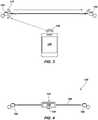
- FIG. 5illustrates another wireless earbud system 150 in accordance with the present disclosure.
- a tether 152may include an electronic control unit 154.
- the electronic control unit 154may include, without limitation, one or more of a battery 156 similar to the battery 148 described in connection with FIG. 3 , an RF receiver, an RF transmitter, a DAC, and an audio amplifier similar to those shown in connection with FIG. 2 , and playback controls 158 such as a play button, stop button, skip to next track, begin previous track, etc.
- playback controls 158such as a play button, stop button, skip to next track, begin previous track, etc.
- the earbuds 160 and 162may receive a wireless signal 136 ( FIG. 3 ) from a media device 134 ( FIG. 3 ) using a master/slave or other arrangement as described above.
- the wireless earbud system 150may operate as shown and described in connection with FIG. 6 .
- a media device 134may broadcast a wireless signal 136 containing audio data as described above in connection with FIG. 3 .
- An RF receiver similar to RF receiver 126 shown in connection with FIG. 2 within the electronic control unit 154may receive the wireless signal 136.
- the wireless signalmay be processed (e.g., decoded) by the DAC in the electronic control unit 154 to provide one or more analog audio channels (e.g., left and right stereo audio channels).
- the left and right analog audio channel signalsmay be directed to respective earbuds 160 and 162 through conductors (not shown) within the tether 152.
- the analog audio signalsmay be amplified by audio amplifiers within the earbuds 160 and 162 similar to audio amplifier 130 described above in connection with FIG. 2 .
- the electronic control unit 154may include one or more audio amplifiers configured to amplify the analog audio signals to a level suitable to drive audio drivers (e.g., audio transducers 118 described in connection with FIG. 2 ).
- Such driver-level signalsmay be transferred through conductors within the tether 152 and fed directly to audio drivers within the earbuds 160 and 162.
- one or more conductors in the tether 152may function as an antenna to enhance reception of the wireless signal 136 by the RF receiver within the electronic control unit 154.
- the playback controls 158 on the electronic control unit 154may be configured to generate signals that may be transmitted wirelessly from the electronic control unit 154 to the media device 134 to control playback of audio tracks from the media device 134.
- operation of the playback controls 158may generate a wireless signal 159 broadcast from an RF transmitter (not shown) within the electronic control unit 154.
- the media device 134may receive the wireless signal and alter audio playback as directed by the user's operation of the playback controls 158.
- the playback controlsmay be buttons arranged on the electronic control unit 154.
- the playback controlsmay be operated by, for example, manipulating (e.g., squeezing) the tether 152.
- manipulatinge.g., squeezing
- at least a portion of the tether 152may be configured to generate a voltage signal (e.g., by changing resistance) when squeezed by the user.
- the wireless earbuds 160 and 162may be configured to collect information from the user and wirelessly transmit the information to the media device 134.
- the wireless earbuds 160 and 162may include sensors configured to sense biometric feedback such as heart rate or body temperature, sensors configured to sense movement (e.g., accelerometers), or other sensors. Information collected by these sensors may be transmitted wirelessly to the media device 134, where it may be organized and processed to provide information (e.g., a heart rate graph, number of steps taken, etc.) to be displayed to the user, posted to social media websites, or similarly employed.
- some wireless earbudsmay suffer from uneven playback between earbuds, e.g., when the playback of left and right audio channels is not suitably synchronized and timing discrepancies between left and right audio channels are audibly noticeable.
- synchronization between the left and right channelscan be maintained with high accuracy, at least because the left and right channels are transmitted by the same wireless signal 136.
- the batteries contained within the individual wireless earbudse.g., battery 122 ( FIG.
- the wireless earbuds 160 and 162must be relatively small and lightweight to ensure that the wireless earbuds remain in the user's ear during activity, some wireless earbuds may have insufficient battery life for extended periods of use.
- the battery 156 in the electronic control unit 154may provide significant additional operating time to the wireless earbuds.
- connecting the wireless earbuds 160 and 162 with the tether 152may prevent loss of a single wireless earbud, particularly during physical activity of the user (e.g., jogging, cycling, etc.). Because the tether 152 is removable, the wireless earbuds 160 and 162 can be used without the tether and the electronic control unit 154 at times when such operation is desired.
- FIGS. 7A through 10Bshow various implementations of detachable connectors (e.g., detachable connectors 114 and 115 as described in connection with FIG. 1 ) according to embodiments of the disclosure.
- FIG. 7Ashows an embodiment of a detachable connector 164 similar to that described with reference to FIG. 1 .
- a distal end 166 of a tether 168may include a plug 170 configured to be inserted within a recess (e.g., a bore, hole, receptacle, etc.) in a housing 172 of a wireless earbud 174.
- a recesse.g., a bore, hole, receptacle, etc.
- the plug 170may include resilient flanges 176 configured to form an interference fit against walls of the recess to retain the plug 170 within the recess, thereby retaining the wireless earbud 174 on the tether 168, as shown in FIG. 7B .
- FIGS. 8A and 8Bshow another embodiment of a detachable connector 178.
- a distal end 180 of a tether 182includes a loop 184 of resilient material such as a flexible polymer.
- a housing 186 of a wireless earbud 188includes a peripheral groove 190.
- the loop 184may fit at least partially within the peripheral groove 190 to retain the wireless earbud 188 on the tether 182, as shown in FIG. 8B .
- FIGS. 9A and 9Bshow another embodiment of a detachable connector 192.
- the detachable connector 192includes a magnetic interface 194 positioned at a distal end 196 of a tether 198.
- a complementary magnetic interface 200is disposed on a housing 202 of a wireless earbud 204.
- One or both of the magnetic interface 194 and the complementary magnetic interface 200may include one or more permanent physical magnets such as ceramic magnets, rare earth magnets, etc.
- one of the magnetic interface 194 and the complementary magnetic interface 200may include magnetic material while the other of the magnetic interface 194 and the complementary magnetic interface 200 may include ferromagnetic material. Magnetic attraction between the magnetic interface 194 and the complementary magnetic interface 200 may retain the distal end 196 of the tether 198 to the housing 202 of the wireless earbud 204, as shown in FIG. 9B .
- FIGS. 10A and 10Bshow yet another embodiment of a detachable connector 206.
- the detachable connector 206includes a pin 208 extending from a connection interface 210 on a distal end 212 of a tether 214.
- a wireless earbud housing 216may include a recess 218 into which the pin 208 may be inserted. An interference fit between the pin 208 and the recess 218 may retain the tether 214 to the wireless earbud housing 216, as shown in FIG. 10B . Referring again to FIG.
- one or more electrically conductive contacts 219may be disposed on the wireless earbud housing 216, and corresponding electrically conductive contacts (not shown) may be disposed on the connection interface 210.
- the electrically conductive contacts 219may be brought into contact with the corresponding electrically conductive contacts of the connection interface 210, thereby connecting electrical circuitry within the wireless earbud housing 216 with electrical conductors in the tether 214.
- the electrically conductive contacts 219 and the corresponding electrically conductive contacts on the connection interface 210may enable transfer of electrical signals between, e.g., the electronic control unit 154 ( FIG. 5 ) and wireless earbuds 160 and 162 ( FIG. 5 ) as described above.
- conductive contacts 219are shown above in FIG. 10A , more than three, or less than three, conductive contacts 219 may be employed, depending on the configuration of the wireless earbuds and the functionality of the tether 214 and the electronic control unit 154 and the required number of discrete electrical pathways therebetween. Furthermore, conductive contacts similar to conductive contacts 219 may be used in connection with any of the detachable connectors (e.g., detachable connectors 164, 178, 192, 206) shown and described above. In other words, inclusion of conductive contacts is not limited to the specific embodiment of the detachable connector shown in FIGS. 10A and 10B .
- FIG. 11illustrates another embodiment of a wireless earbud system 220 in accordance with the present disclosure.
- the wireless earbud system 220includes an electronic control unit 222 with a housing 224 configured to accept wireless earbuds 226 and 228 for storage and/or charging.
- the housing 224 of the electronic control unit 222may include a recessed area with a profile at least partially matching the shape of the wireless earbuds 226 and 228 such that the wireless earbuds can be positioned at least partially within the housing 224.
- Electrical contacts(not shown) may be disposed within the housing 224 and positioned to make contact with electrical contacts (e.g., conductive contacts 219 described in connection with FIG.
- batteriese.g., battery 122 discussed above in connection with FIG. 2
- the wireless earbuds 226 and 228using power from a battery within the electronic control unit 222 (e.g., battery 156 as discussed above in connection with FIG. 5 ) or a charging cable attached to the electronic control unit 222 and plugged into a charging port 149 ( FIG. 4 ).
- the batteries 122 within the earbudsmay be charged by the battery 156 within the electronic control unit 222.
- the batteries 122 and the battery 156may charge simultaneously.
- the wireless earbuds 226 and 228may attach to one another at an interface 230.
- interface 230may be a magnetic connection interface, e.g., similar to that described above in connection with FIGS. 9A and 9B .
- the interface 230may include mechanical connectors, such as tabs or pins and complementary slots or receptacles, etc.
- the wireless earbuds 226 and 228may each include a power switch 232 disposed on or adjacent to the interface 230.
- the power switch 232may be configured to automatically power off each wireless earbuds 226, 228 when the wireless earbuds 226, 228 are connected at the interface 230, and to automatically power on the wireless earbuds when the wireless earbuds are detached from one another at the interface 230.
- the power switches 232may prevent excessive power consumption when the earbuds are not in use and thus improve (e.g., maximize) battery life.
- the power switches 232may be mechanical (e.g., plunger) switches or switches without moving parts, such as magnetic switches (e.g., hall effect switches) that change conductivity based on the presence of a magnetic field (e.g., a magnetic field associated with magnets of a magnetic connection interface between the wireless earbuds 226 and 228).
- a magnetic fielde.g., a magnetic field associated with magnets of a magnetic connection interface between the wireless earbuds 226 and 228).
- FIGS. 12A and 12Billustrate another embodiment of an electrical control unit 234 according to the present disclosure.
- the electrical control unit 234may include playback controls 236 ( FIG. 12B ), such as play, stop, next track, and previous track buttons.
- the electrical control unit 234may also include a clip, e.g., a spring-loaded clip 238 ( FIG. 12A ) configured to attach to a user's clothing, e.g., collar, placket, lapel, etc., for convenience.
- the electrical control unit 234may include a tether 240 similar to, e.g., the tether 152 described above with reference to FIG. 5 .
- the electrical control unit 234may include functionality similar to the electronic control unit 154 described with reference to FIG. 5 .
- the wireless earbud system 100may include software executable by the media device 134 ( FIG. 3 ).
- such softwaremay include a graphical user interface (GUI) for display on a display screen of the media device 134.
- GUIgraphical user interface
- the GUImay include information related to the battery charge in each earbud, the battery charge in the electronic control unit 154 ( FIG. 5 ), 234 ( FIGS. 12A and 12B ), playback mode (e.g., master-slave configuration or direct transmission to both earbuds as discussed in connection with FIG. 3 ), and other operational parameters of the earbud system.
Landscapes
- Engineering & Computer Science (AREA)
- Physics & Mathematics (AREA)
- Life Sciences & Earth Sciences (AREA)
- Health & Medical Sciences (AREA)
- Acoustics & Sound (AREA)
- Signal Processing (AREA)
- Surgery (AREA)
- Public Health (AREA)
- Biomedical Technology (AREA)
- Heart & Thoracic Surgery (AREA)
- Medical Informatics (AREA)
- Molecular Biology (AREA)
- Biophysics (AREA)
- Animal Behavior & Ethology (AREA)
- General Health & Medical Sciences (AREA)
- Pathology (AREA)
- Veterinary Medicine (AREA)
- Biodiversity & Conservation Biology (AREA)
- Manufacturing & Machinery (AREA)
- Computer Networks & Wireless Communication (AREA)
- Headphones And Earphones (AREA)
- Circuit For Audible Band Transducer (AREA)
- Telephone Function (AREA)
- Telephone Set Structure (AREA)
Description
- The present disclosure relates generally to earbud headphones, and more specifically to earbuds configured to receive a wireless data signal from a media device.
- Earbud headphones are used to convert an electronic signal into an audible sound, which is transmitted to the ear of a person using the earbud headphones. Earbud headphones are used in conjunction with many different types of electronic devices, such as media players, hearing aids, cellular telephones, televisions, computers,etc. In contrast to what are referred to in the industry as "on-ear" headphones and "over-ear" headphones, earbud headphones are relatively small headphones that rest within the concha of the outer ear and are often referred to as "in-ear" headphones. Earbud headphones are retained in place by the cooperation and mechanical interference between the earbud headphone and the ear of the user. Some earbud headphones include a portion that is sized and configured to extend from a main body of the headphone into the external auditory canal of the ear.
- Earbud headphones are popular among users because they are generally relatively small and portable. Moreover, when a user is participating in various activities, earbud headphones interfere to a much lesser extent with the other accessories or equipment of the user, such as helmets, goggles, hats, and headbands compared to on-ear and over-ear headphones, which often include a headband or other connecting structure (in addition to wiring) extending around the head of the user between each headphone.
- Some earbud headphones may include wireless functionality. For example, data from a media player may be transmitted by radio frequency (RF) signals from a media device to a wireless earbud. Wireless protocols such as Wi-Fi, Bluetooth®, or other protocols may be used for wireless transmission.
- The document
US 2015/0230019 A1 discloses an electronic wearable device including an electrical cord for carrying electrical signals. An electrical power module includes an interface for detachable connection to the electrical cord. A first audio module includes an interface for detachable connecting to the electrical cord. A second audio module includes an interface for detachable connecting to the electrical cord. The electrical cord is configured to support the first audio module and the second audio module thereon. - The document
US 2005/0136839 A1 discloses a modular wireless headset including wearable earpiece(s) and wearable microphone(s), wherein the earpiece and microphone may be physically separate devices. The wearable earpiece renders inbound radio frequencies received from a host device audible. The wearable earpiece may include a receiver module, data recovery module, and speaker module. The receiver module may convert inbound RF signals into low intermediate frequency (IF) signals. The data recovery module recovers audio signals from the low IF signals. - The document
WO 2016/032011 A1 discloses a wireless headset including a main body and sub-bodies detachably attached to both lateral ends of the main body by a retractable cable. Earpieces are detachably attached to the sub-bodies and configured to output a sound when supportedly installed in the sub-bodies and a controller is configured to output the sound wirelessly through the earpieces when the earpieces are separated from the sub-bodies. - The document
EP 2 506 597 A1 discloses a wireless listening device that can be used in conjunction with a host device to provide an end user a pleasurable listening experience especially during periods of physical activity. The host device can take the form of a portable media player. - The document
WO 2012/024656 A2 discloses ear bud headphones configured for use with a portable media player including a main body portion with an extended curvature configuration. The ear bud headphones include a speaker housing and an extension that form a gap between the speaker housing and the extension. The user can secure a portion of the user's outer ear in the gap such that the ear bud is securely and comfortably held in place within a user's ear. - The invention is defined by the appended set of claims.
- According to an aspect of the invention, a wireless earbud system includes a first earbud assembly and a second earbud assembly. Each of the first earbud assembly and the second earbud assembly includes a housing, an audio driver disposed within the housing, and a wireless receiving unit operatively coupled to the audio driver. The wireless receiving unit is configured to receive a wireless data signal and drive the audio driver based on audio data transmitted in the wireless data signal. The wireless earbud system further includes a tether with a first end and a second end. The first end of the tether is configured to removably couple to the first earbud assembly by a first detachable connector, and the second end of the tether is configured to removably couple to the second earbud assembly by a second detachable connector. The tether also includes an electronic control unit disposed intermediate the first end of the tether and the second end of the tether.
- In another aspect, a wireless earbud system includes a first earbud assembly and a second earbud assembly. Each of the first earbud assembly and the second earbud assembly include an audio driver, a wireless receiving unit operatively coupled to the audio driver, the wireless receiving unit configured to receive a wireless data signal, and an earbud battery configured to supply power to one or both of the audio driver and the wireless receiving unit. The wireless earbud system also includes a tether including a first end with a first detachable connector configured to mechanically and electrically couple the first end of the tether to the first earbud assembly, and a second end with a second detachable connector configured to mechanically and electrically couple the second end of the tether to the second earbud assembly. The electronic control unit includes a wireless unit configured to receive a wireless data signal from a media device and to transmit an audio signal based on the wireless data signal through electrical conductors in the tether to the first and second earbud assemblies when the first and second earbud assemblies are coupled to the first and second ends of the tether, respectively, and an electronic control unit battery configured to supply power to the wireless unit.
- Also according to another aspect of the invention, a method of forming a wireless earbud system includes forming an electronic control unit comprising a wireless unit, a battery, and a tether. The method also includes forming first and second wireless earbud assemblies, and configuring first and second ends of the tether to removably couple to the first and second wireless earbud assemblies. The method also includes configuring one or both of the first and second wireless earbud assemblies to receive a wireless signal from a media device and to drive audio drivers in the first and second wireless earbud assemblies with an audio signal based on data received from the media device when the first and second ends of the tether are decoupled from the first and second wireless earbud assemblies, and configuring the wireless unit of the electronic control unit to receive a wireless signal from the media device and to drive the audio drivers in the first and second wireless earbud assemblies through electrical conductors disposed within the tether with an audio signal based on data received wirelessly from the media device when the first and second ends of the tether are respectively coupled to the first and second earbud assemblies.
FIG. 1 is a plan view of an embodiment of an earbud system according to the disclosure;FIG. 2 is a schematic diagram of components of an earbud according to the disclosure;FIG. 3 is a schematic diagram showing operation of an earbud system according to the disclosure;FIG. 4 is a plan view of another embodiment of an earbud system according to the disclosure;FIG. 5 is a plan view of yet another embodiment of an earbud system according to the disclosure;FIG. 6 is a schematic diagram showing an operational configuration of the earbud system ofFIG. 5 ;FIGS. 7A and 7B are perspective views of an earbud and a detachable connector according to an embodiment of the disclosure;FIGS. 8A and 8B are perspective views of an earbud and a detachable connector according to another embodiment of the disclosure;FIGS. 9A and 9B are perspective views of an earbud and a detachable connector according to yet another embodiment of the disclosure;FIGS. 10A and 10B are perspective views of an earbud and a detachable connector according to yet another embodiment of the disclosure;FIG. 11 is a plan view of yet another embodiment of an earbud system according to the disclosure; andFIGS. 12A and 12B are perspective views of an electronic control unit according to an embodiment of the disclosure.- The illustrations presented herein are not meant to be actual views of any particular headphone or component thereof, but are merely idealized representations employed to describe various embodiments of the disclosure.
- The disclosure relates to earbud headphones configured to communicate wirelessly (e.g., through radio frequency (RF) electromagnetic waves) with a media device. The earbud headphones may include a tether that mechanically and/or electrically couples the earbud headphones to one another. The earbud headphones may function differently when connected by the tether compared to when the earbud headphones are used without the tether.
FIG. 1 is a plan view of awireless earbud system 100 according to the disclosure. Thewireless earbud system 100 may include afirst earbud 102 and asecond earbud 104. Thefirst earbud 102 and thesecond earbud 104 may include afirst earbud housing 106 and asecond earbud housing 108, respectively. Thewireless earbud system 100 includes atether 110 formed of a lightweight, flexible material, such as a woven fabric cord, a polymer (plastic, elastomeric, etc.) cord, etc. Thetether 110 may include afirst end 112 and asecond end 113. Thefirst end 112 and thesecond end 113 may includedetachable connectors detachable connectors first end 112 of thetether 110 to thefirst earbud 102, and thesecond end 113 of thetether 110 to thesecond earbud 104. For example, each of thedetachable connectors plug 116 configured for insertion into a corresponding recess of the first orsecond earbud - The first and
second wireless earbuds tether 110 to, e.g., prevent loss of an individual one of the first andsecond earbuds tether 110 may alter the functionality of the wireless earbuds, as described in detail below in connection withFIGS. 4 ,5, and 6 . In some embodiments, thedetachable connectors second wireless earbuds detachable connectors second wireless earbuds detachable connectors detachable connectors second wireless earbuds tether 110. Such electrical connections are described in detail below in connection withFIGS. 10A and 10B . FIG. 2 is a schematic representation ofcomponents 117 within an earbud headphone (e.g., thefirst earbud 102 or thesecond earbud 104 ofFIG. 1 ). Thecomponents 117 within the earbud headphone may include, without limitation, anaudio transducer 118, awireless audio unit 120, and abattery 122. Theaudio transducer 118 may be an electromechanical device configured to receive an analog electrical signal containing audio information and convert the electrical energy to sound waves (e.g., physical vibrations with a frequency of about 20 Hz to about 20 kHz). In some embodiments, each of thefirst earbud 102 and thesecond earbud 104 may include a plurality ofaudio transducers 118. In some embodiments, each of thefirst earbud 102 and thesecond earbud 104 may include an enclosure tuned with respect to theaudio transducer 118 to enhance (e.g., increase) the output of theaudio transducer 118 within a particular range of frequencies. In addition, some embodiments may include a tuned port or a tuned diaphragm configured to enhance the output of theaudio transducer 118 within a particular frequency range.- The
wireless audio unit 120 may include circuitry configured to receive wireless signals and transmit wireless signals. Thewireless audio unit 120 may also include circuitry configured to decode a digital wireless signal. For example, thewireless audio unit 120 may include circuitry configured to convert a digital signal to an analog audio signal. In one embodiment, the wireless unit may include anRF receiver 126 operatively coupled to a digital-to-analog converter (DAC) 128. An audio amplifier 130 may be operatively coupled to an analog output of the DAC 128 and configured to amplify the analog audio output from the DAC 128 to a level suitable to drive theaudio transducer 118. Thewireless audio unit 120 may also include an RF transmitter (not shown) configured to broadcast a wireless signal, as discussed below. - The
battery 122 may be configured to supply electrical current to thewireless audio unit 120. In other words, current from thebattery 122 may be consumed by theRF receiver 126, the DAC 128, and the audio amplifier 130. Thebattery 122 may be, for example, a rechargeable lithium-ion battery, or any other battery with suitable energy density. - In some embodiments, the
first earbud 102 and thesecond earbud 104 may include components and circuitry to provide active noise cancelling (ANC) functionality. For example, each of thefirst earbud 102 and thesecond earbud 104 may include a microphone for converting ambient noises to electrical signals. Signal processing circuitry may generate electrical signals representing sounds identical to the ambient sounds but in opposite phase. The opposite-phase ambient sounds may be reproduced through theaudio transducer 118 to cancel the ambient sounds. FIG. 3 is a schematic diagram showing an operational mode of the wireless earbud system 100 (FIG. 1 ). Amedia device 134 may be configured to broadcast awireless signal 136 containing data representing an audio signal. Themedia device 134 may be, for example, a handheld device such as a cellular "smart" phone, a tablet computer, a digital music player, a laptop computer, a desktop computer, etc. In the embodiment shown inFIG. 3 , thewireless earbuds earbuds FIG. 2 ) in the earbud 102) may receive thewireless signal 136 from themedia device 134. Thewireless signal 136 from themedia device 134 may be separated into left and right audio channels by circuitry and/or software routines associated with the "master" earbud. Data from one audio channel (e.g., one of left or right) may be converted to an audio signal, amplified, and played through an audio transducer 118 (FIG. 2 ) in the "master" earbud. Data from the other audio channel (e.g., the other of the left or right channels) may be transmitted wirelessly (e.g., by wireless signal 137) from an RF transmitter within the "master" earbud to an RF receiver (e.g., RF receiver 126) within the "slave" earbud, where the data is converted to an audio signal, amplified, and played through anaudio transducer 118 in the "slave" earbud.- Operation as the "master" earbud may consume significantly more power than operation as the "slave" earbud, as the "master" earbud must separate the channels and re-transmit one of the channels to the "slave" earbud. Accordingly, in some embodiments, each of the
earbuds earbuds earbud 102 and theearbud 104. In other embodiments, the particular earbud that functions as the "master" or "slave" may be chosen by other routines based on remaining charge in each battery and/or other parameters. Furthermore, while the above description assumes theearbuds media device 134 may include only a single channel of audio data (i.e., monophonic sound). Such data may be received and played by one of theearbuds earbuds - In some embodiments, the
media device 134 may broadcast a wireless signal that is received directly by each of thefirst earbud 102 andsecond earbud 104. In other words, neither of thefirst earbud 102 and thesecond earbud 104 function as "master" or "slave," but each receives thewireless signal 136 directly from themedia device 134. When operating in this arrangement, each of theearbuds wireless signal 136 corresponding to one of the left or right channels to an analog audio signal (e.g., by processing a portion of thewireless signal 136 through the DAC 128 and audio amplifier 130) and play the audio signal through an audio transducer 118 (FIG. 2 ). - The
wireless signal 136 may be broadcast by themedia device 134 based on established wireless protocols, such as the Bluetooth® Advanced Audio Distribution Profile (A2DP). Additionally or alternatively, other wireless protocols (e.g., Wi-Fi), may be used. FIG. 4 illustrates another embodiment of awireless earbud system 138 according to the disclosure. Inwireless earbud system 138, atether 140 may includeelectronic components 142 configured to be operatively connected to (e.g., by electricallyconductive contacts 219 described below in connection withFIGS. 10A and 10B ) afirst earbud 144 and asecond earbud 146 when thefirst earbud 144 and thesecond earbud 146 are connected by thetether 140. For example, in the embodiment shown inFIG. 3 , theelectronic components 142 may include abattery 148 configured to provide power to operate one or more of the RF receiver 126 (FIG. 2 ), RF transmitter (not illustrated), DAC 128 (FIG. 2 ), and audio amplifier 130 (FIG. 2 ) of each of theearbuds tether 140 is connected to thefirst earbud 144 and thesecond earbud 146. Furthermore, thebattery 148 may be configured to charge (e.g., recharge) batteries (e.g.,battery 122 described in connection withFIG. 2 ) in thewireless earbuds tether 140 is connected to thefirst earbud 144 and thesecond earbud 146. When thetether 140 is connected to one or both of thefirst earbud 144 and thesecond earbud 146, the electronic componentry within theearbuds battery 148 in thetether 140 and thebatteries 122 within theindividual earbuds battery 148 may be a lithium-ion rechargeable battery as discussed above, or a battery with different chemistry and/or construction. In some embodiments, thebattery 148 may be charged by connecting a charging cable (e.g., micro USB, mini USB, USB-C) between a chargingport 149 operatively coupled to thebattery 148 and a power source (e.g., a USB port of a computer, charging station, etc.).FIG. 5 illustrates anotherwireless earbud system 150 in accordance with the present disclosure. In the embodiment ofFIG. 5 , atether 152 may include anelectronic control unit 154. Theelectronic control unit 154 may include, without limitation, one or more of abattery 156 similar to thebattery 148 described in connection withFIG. 3 , an RF receiver, an RF transmitter, a DAC, and an audio amplifier similar to those shown in connection withFIG. 2 , and playback controls 158 such as a play button, stop button, skip to next track, begin previous track, etc. When thetether 152 is disconnected fromearbuds earbuds earbuds FIG. 3 . In other words, when thetether 152 is disconnected from theearbuds earbuds FIG. 3 ) from a media device 134 (FIG. 3 ) using a master/slave or other arrangement as described above.- When the
tether 152 is connected to theearbuds wireless earbud system 150 may operate as shown and described in connection withFIG. 6 . Amedia device 134 may broadcast awireless signal 136 containing audio data as described above in connection withFIG. 3 . An RF receiver similar toRF receiver 126 shown in connection withFIG. 2 within theelectronic control unit 154 may receive thewireless signal 136. The wireless signal may be processed (e.g., decoded) by the DAC in theelectronic control unit 154 to provide one or more analog audio channels (e.g., left and right stereo audio channels). The left and right analog audio channel signals may be directed torespective earbuds tether 152. The analog audio signals may be amplified by audio amplifiers within theearbuds FIG. 2 . Additionally or alternatively, theelectronic control unit 154 may include one or more audio amplifiers configured to amplify the analog audio signals to a level suitable to drive audio drivers (e.g.,audio transducers 118 described in connection withFIG. 2 ). Such driver-level signals may be transferred through conductors within thetether 152 and fed directly to audio drivers within theearbuds tether 152 may function as an antenna to enhance reception of thewireless signal 136 by the RF receiver within theelectronic control unit 154. - The playback controls 158 on the
electronic control unit 154 may be configured to generate signals that may be transmitted wirelessly from theelectronic control unit 154 to themedia device 134 to control playback of audio tracks from themedia device 134. For example, operation of the playback controls 158 may generate awireless signal 159 broadcast from an RF transmitter (not shown) within theelectronic control unit 154. Themedia device 134 may receive the wireless signal and alter audio playback as directed by the user's operation of the playback controls 158. - In some embodiments, the playback controls may be buttons arranged on the
electronic control unit 154. In other embodiments, the playback controls may be operated by, for example, manipulating (e.g., squeezing) thetether 152. For example, at least a portion of thetether 152 may be configured to generate a voltage signal (e.g., by changing resistance) when squeezed by the user. - In some embodiments, the
wireless earbuds electronic control unit 154, or both may be configured to collect information from the user and wirelessly transmit the information to themedia device 134. For example, thewireless earbuds media device 134, where it may be organized and processed to provide information (e.g., a heart rate graph, number of steps taken, etc.) to be displayed to the user, posted to social media websites, or similarly employed. - When operating in the configuration described with reference to
FIG. 6 , certain limitations of some wireless earbuds may be mitigated. For example, at times, some wireless earbuds may suffer from uneven playback between earbuds, e.g., when the playback of left and right audio channels is not suitably synchronized and timing discrepancies between left and right audio channels are audibly noticeable. When connected by thetether 152, synchronization between the left and right channels can be maintained with high accuracy, at least because the left and right channels are transmitted by thesame wireless signal 136. Moreover, as the batteries contained within the individual wireless earbuds (e.g., battery 122 (FIG. 2 )) must be relatively small and lightweight to ensure that the wireless earbuds remain in the user's ear during activity, some wireless earbuds may have insufficient battery life for extended periods of use. When connected by thetether 152, thebattery 156 in theelectronic control unit 154 may provide significant additional operating time to the wireless earbuds. Finally, connecting thewireless earbuds tether 152 may prevent loss of a single wireless earbud, particularly during physical activity of the user (e.g., jogging, cycling, etc.). Because thetether 152 is removable, thewireless earbuds electronic control unit 154 at times when such operation is desired. FIGS. 7A through 10B show various implementations of detachable connectors (e.g.,detachable connectors FIG. 1 ) according to embodiments of the disclosure.FIG. 7A shows an embodiment of adetachable connector 164 similar to that described with reference toFIG. 1 . Adistal end 166 of atether 168 may include aplug 170 configured to be inserted within a recess (e.g., a bore, hole, receptacle, etc.) in ahousing 172 of awireless earbud 174. Theplug 170 may includeresilient flanges 176 configured to form an interference fit against walls of the recess to retain theplug 170 within the recess, thereby retaining thewireless earbud 174 on thetether 168, as shown inFIG. 7B .FIGS. 8A and 8B show another embodiment of adetachable connector 178. In this embodiment, adistal end 180 of atether 182 includes aloop 184 of resilient material such as a flexible polymer. Ahousing 186 of awireless earbud 188 includes aperipheral groove 190. Theloop 184 may fit at least partially within theperipheral groove 190 to retain thewireless earbud 188 on thetether 182, as shown inFIG. 8B .FIGS. 9A and 9B show another embodiment of adetachable connector 192. Thedetachable connector 192 includes amagnetic interface 194 positioned at adistal end 196 of atether 198. A complementarymagnetic interface 200 is disposed on ahousing 202 of awireless earbud 204. One or both of themagnetic interface 194 and the complementarymagnetic interface 200 may include one or more permanent physical magnets such as ceramic magnets, rare earth magnets, etc. In some embodiments, one of themagnetic interface 194 and the complementarymagnetic interface 200 may include magnetic material while the other of themagnetic interface 194 and the complementarymagnetic interface 200 may include ferromagnetic material. Magnetic attraction between themagnetic interface 194 and the complementarymagnetic interface 200 may retain thedistal end 196 of thetether 198 to thehousing 202 of thewireless earbud 204, as shown inFIG. 9B .FIGS. 10A and 10B show yet another embodiment of adetachable connector 206. In this embodiment, thedetachable connector 206 includes apin 208 extending from aconnection interface 210 on adistal end 212 of atether 214. Awireless earbud housing 216 may include arecess 218 into which thepin 208 may be inserted. An interference fit between thepin 208 and therecess 218 may retain thetether 214 to thewireless earbud housing 216, as shown inFIG. 10B . Referring again toFIG. 10A , one or more electricallyconductive contacts 219 may be disposed on thewireless earbud housing 216, and corresponding electrically conductive contacts (not shown) may be disposed on theconnection interface 210. When thepin 208 is fully inserted within therecess 218, the electricallyconductive contacts 219 may be brought into contact with the corresponding electrically conductive contacts of theconnection interface 210, thereby connecting electrical circuitry within thewireless earbud housing 216 with electrical conductors in thetether 214. The electricallyconductive contacts 219 and the corresponding electrically conductive contacts on theconnection interface 210 may enable transfer of electrical signals between, e.g., the electronic control unit 154 (FIG. 5 ) andwireless earbuds 160 and 162 (FIG. 5 ) as described above.- While three (3)
conductive contacts 219 are shown above inFIG. 10A , more than three, or less than three,conductive contacts 219 may be employed, depending on the configuration of the wireless earbuds and the functionality of thetether 214 and theelectronic control unit 154 and the required number of discrete electrical pathways therebetween. Furthermore, conductive contacts similar toconductive contacts 219 may be used in connection with any of the detachable connectors (e.g.,detachable connectors FIGS. 10A and 10B . FIG. 11 illustrates another embodiment of awireless earbud system 220 in accordance with the present disclosure. Thewireless earbud system 220 includes anelectronic control unit 222 with ahousing 224 configured to acceptwireless earbuds housing 224 of theelectronic control unit 222 may include a recessed area with a profile at least partially matching the shape of thewireless earbuds housing 224. Electrical contacts (not shown) may be disposed within thehousing 224 and positioned to make contact with electrical contacts (e.g.,conductive contacts 219 described in connection withFIG. 10A ) on one or both of thewireless earbuds battery 122 discussed above in connection withFIG. 2 ) within thewireless earbuds battery 156 as discussed above in connection withFIG. 5 ) or a charging cable attached to theelectronic control unit 222 and plugged into a charging port 149 (FIG. 4 ). For example, when theelectronic control unit 222 is not attached to a charging cable, thebatteries 122 within the earbuds may be charged by thebattery 156 within theelectronic control unit 222. When theelectronic control unit 222 is attached to a charging cable, thebatteries 122 and thebattery 156 may charge simultaneously.- In some embodiments, the
wireless earbuds interface 230. For example,interface 230 may be a magnetic connection interface, e.g., similar to that described above in connection withFIGS. 9A and 9B . In other embodiments, theinterface 230 may include mechanical connectors, such as tabs or pins and complementary slots or receptacles, etc. - The
wireless earbuds power switch 232 disposed on or adjacent to theinterface 230. Thepower switch 232 may be configured to automatically power off eachwireless earbuds wireless earbuds interface 230, and to automatically power on the wireless earbuds when the wireless earbuds are detached from one another at theinterface 230. The power switches 232 may prevent excessive power consumption when the earbuds are not in use and thus improve (e.g., maximize) battery life. The power switches 232 may be mechanical (e.g., plunger) switches or switches without moving parts, such as magnetic switches (e.g., hall effect switches) that change conductivity based on the presence of a magnetic field (e.g., a magnetic field associated with magnets of a magnetic connection interface between thewireless earbuds 226 and 228). FIGS. 12A and 12B illustrate another embodiment of anelectrical control unit 234 according to the present disclosure. Theelectrical control unit 234 may include playback controls 236 (FIG. 12B ), such as play, stop, next track, and previous track buttons. Theelectrical control unit 234 may also include a clip, e.g., a spring-loaded clip 238 (FIG. 12A ) configured to attach to a user's clothing, e.g., collar, placket, lapel, etc., for convenience. Theelectrical control unit 234 may include atether 240 similar to, e.g., thetether 152 described above with reference toFIG. 5 . Theelectrical control unit 234 may include functionality similar to theelectronic control unit 154 described with reference toFIG. 5 .- In some embodiments, the wireless earbud system 100 (
FIG. 1 ), 138 (FIG. 4 ), 150 (FIG. 5, 6 ), or 220 (FIG. 11 ) may include software executable by the media device 134 (FIG. 3 ). For example, such software may include a graphical user interface (GUI) for display on a display screen of themedia device 134. The GUI may include information related to the battery charge in each earbud, the battery charge in the electronic control unit 154 (FIG. 5 ), 234 (FIGS. 12A and 12B ), playback mode (e.g., master-slave configuration or direct transmission to both earbuds as discussed in connection withFIG. 3 ), and other operational parameters of the earbud system.
Claims (15)
- A wireless earbud system (100), comprising:
a first earbud assembly and a second earbud assembly, each of the first earbud assembly and the second earbud assembly comprising:a housing (106. 108, 172, 202, 216);an audio driver disposed within the housing (106. 108, 172, 202, 216); anda wireless receiving unit operatively coupled to the audio driver, the wireless receiving unit configured to receive a wireless data signal and drive the audio driver based on audio data transmitted in the
wireless data signal;the wirelessearbud system (100) additionally comprising a tether (110, 140, 152, 168, 182, 198, 214, 240) with a first end (112), a second end (113), and an electronic control unit (154, 222) located between the first end (112) and the second end (113), wherein the first end (112) of the tether (110,.. 240) is configured to removably couple to the first earbud assembly by a first detachable connector, (114, 115) wherein the second end (113) of the tether (110,.. 240) is configured to removably couple to the second earbud assembly by a second detachable connector (114, 115), andwherein one of the first earbud assembly and the second earbud assembly is configured to operate as a master and communicate directly with a media device (134) when the first end (112) and the second end (113) of the tether (110,.. 240) are disconnected from the first earbud assembly and the second earbud assembly, andwherein the electronic control unit (154, 222) is configured to communicate directly with the media device (134), with the first earbud assembly and the second earbud assembly communicating directly with the electronic control unit (154, 222), when the first end (112) of the tether (110,.. 240) is connected to the first earbud assembly and the second end (113) of the tether (110,.. 240) is connected to the second earbud assembly. - The wireless earbud system (100) of claim 1, wherein each of the first detachable connector (114, 115) and the second detachable connector (114, 115) comprise electrical contacts operatively coupling the electronic control unit (154, 222) in the tether (110,.. 240) respectively with the first earbud assembly and the second earbud assembly.
- The wireless earbud system (100) of claim 2, wherein the first earbud assembly comprises a first earbud battery (122, 148, 156) and the second earbud assembly comprises a second earbud battery (122, 148, 156), wherein the electronic control unit (154, 222) comprises a control unit battery, and wherein one or both of the first earbud battery (122, 148, 156) and the audio driver in the first earbud assembly, and one or both of the second earbud battery (122, 148, 156) and the audio driver in the second earbud assembly, are configured to draw electrical power from the control unit battery when the first end (112) of the tether (110,.. 240) is coupled to the first earbud assembly and the second end (113) of the tether (110,.. 240) is coupled to the second earbud assembly.
- The wireless earbud system (100) of claim 2 or claim 3, wherein the electronic control unit (154, 222) in the tether (110,.. 240) comprises a wireless receiver configured to receive a wireless data signal from a media device (134) and transmit an audio signal through the tether (110,.. 240) directly to the audio drivers of the first and second earbud assemblies through electrical conductors when the first and second ends (112, 113)of the tether (110,.. 240) are respectively coupled with the first and second earbud assemblies.
- The wireless earbud system (100) of any one of claims 2 through 4, wherein the electronic control unit (154, 222) comprises one or more playback controls (158, 236), and wherein the wireless unit is configured to transmit playback instructions from the playback controls (158, 236) to a media device (134).
- The wireless earbud system (100) of any one of claims 2 through 5, wherein the electronic control unit (154, 222) comprises a housing (224) configured to store the first earbud assembly and the second earbud assembly.
- The wireless earbud system (100) of claim 6, wherein the first earbud assembly and the second earbud assembly are configured to couple to one another for storage in the electronic control unit housing (224).
- The wireless earbud system (100) of claim 7, wherein the first earbud assembly and the second earbud assembly each include electronic switches (232) configured to power off the first earbud assembly and the second earbud assembly when the first earbud assembly and the second earbud assembly are coupled to one another.
- The wireless earbud system (100) of claim 8, wherein the electronic switches (232) are configured to automatically power on the first earbud assembly and the second earbud assembly when the first earbud assembly is decoupled from the second earbud assembly.
- The wireless earbud system (100) of any one of claims 1 through 9, wherein the first detachable connector (114, 115) and the second detachable connector (114, 115) each comprise a peripheral groove (190) in a portion of the first and second respective earbud housings (106. 108, 172, 202, 216) and first and second resilient loops (184) at the first and second respective ends of the tether (110,.. 240), and wherein the first and second resilient loops (184) are configured to fit at least partially within a respective one of the peripheral grooves (190) to retain the first and second ends (112, 113) of the tether (110,.. 240) to the first and second respective earbud housings (106. 108, 172, 202, 216).
- The wireless earbud system (100) of any one of claims 1 through 9, wherein the first detachable connector (114, 115) and the second detachable connector (114, 115) each comprise a magnetic interface (194) on each of the first and second ends (112, 113) of the tether (110,.. 240) and a complementary magnetic interface (200) on each of the first and second earbud housings (106. 108, 172, 202, 216).
- The wireless earbud system (100) of any one of claims 1 through 9, wherein the first detachable connector (114, 115) and the second detachable connector (114, 115) each comprise a plug (170) on each of the first and second ends (112, 113) of the tether (110,.. 240) configured for insertion within a respective complimentary recess disposed in each of the first and second earbud housings (106. 108, 172, 202, 216).
- The wireless earbud system (100) of any one of claims 1 through 12, wherein the wireless receiving unit in the first earbud assembly and the wireless receiving unit in the second earbud assembly are each configured to receive a wireless signal from a media device (134) and to send a wireless signal to the wireless receiving unit in the other of the first earbud assembly and the second earbud assembly.
- The wireless earbud system (100) of any one of claims 1 through 13, wherein at least one of the first earbud assembly and the second earbud assembly comprise a sensor configured to sense biometric feedback, and wherein at least one of the wireless receiving unit in the first earbud assembly and the wireless receiving unit in the second earbud assembly are configured to transmit a wireless data signal based on the biometric feedback to a media device (134).
- A method of forming a wireless earbud system (100), the method comprising:forming an electronic control unit (154, 222) comprising a wireless unit, a battery, and a tether (110,.. 240);forming first and second wireless earbud assemblies;configuring first and second ends (112, 113) of the tether (110,.. 240) to removably couple to the first and second wireless earbud assemblies;configuring one of the first and second wireless earbud assemblies to operate in a master mode and receive a wireless signal directly from a media device (134) and to drive audio drivers in the first and second wireless earbud assemblies with an audio signal based on data received directly from the media device (134) when the first and second ends (112, 113) of the tether (110,.. 240) are decoupled from the first and second wireless earbud assemblies;configuring the wireless unit of the electronic control unit (154, 222) to receive a wireless signal directly from the media device (134) and to drive the audio drivers in the first and second wireless earbud assemblies through electrical conductors disposed within the tether (110,.. 240) with an audio signal based on data received directly wirelessly from the media device (134) when the first and second ends (112, 113) of the tether (110,.. 240) are respectively coupled to the first and second earbud assemblies.
Applications Claiming Priority (1)
| Application Number | Priority Date | Filing Date | Title |
|---|---|---|---|
| US201562253250P | 2015-11-10 | 2015-11-10 |
Publications (3)
| Publication Number | Publication Date |
|---|---|
| EP3169081A2 EP3169081A2 (en) | 2017-05-17 |
| EP3169081A3 EP3169081A3 (en) | 2017-09-13 |
| EP3169081B1true EP3169081B1 (en) | 2019-07-10 |
Family
ID=57286282
Family Applications (1)
| Application Number | Title | Priority Date | Filing Date |
|---|---|---|---|
| EP16197949.7AActiveEP3169081B1 (en) | 2015-11-10 | 2016-11-09 | Wireless earbuds and related methods |
Country Status (3)
| Country | Link |
|---|---|
| US (2) | US9900680B2 (en) |
| EP (1) | EP3169081B1 (en) |
| CN (1) | CN106878847B (en) |
Families Citing this family (63)
| Publication number | Priority date | Publication date | Assignee | Title |
|---|---|---|---|---|
| USD736174S1 (en) | 2014-02-10 | 2015-08-11 | New Audio LLC | Headphone device |
| USD727280S1 (en) | 2014-02-10 | 2015-04-21 | New Audio LLC | Headphone device |
| USD741842S1 (en) | 2014-07-07 | 2015-10-27 | New Audio LLC | Microphone accessory |
| USD774489S1 (en)* | 2014-09-03 | 2016-12-20 | Sennheiser Electronic Gmbh & Co. Kg | Pair of earphones |
| USD781265S1 (en) | 2015-08-07 | 2017-03-14 | New Audio LLC | Headset |
| US9729954B2 (en) | 2015-08-07 | 2017-08-08 | New Audio LLC | Audio headset having internal cord management features and related technology |
| US9900680B2 (en)* | 2015-11-10 | 2018-02-20 | Skullcandy, Inc. | Wireless earbuds and related methods |
| US9825355B2 (en)* | 2015-12-18 | 2017-11-21 | Motorola Mobility Llc | Wireless stereo headset antenna system |
| US20170295421A1 (en)* | 2016-04-12 | 2017-10-12 | Mavin Technology Inc. | Wireless earphone set |
| USD817301S1 (en)* | 2016-08-26 | 2018-05-08 | Apple Inc. | Headphones |
| US10042595B2 (en) | 2016-09-06 | 2018-08-07 | Apple Inc. | Devices, methods, and graphical user interfaces for wireless pairing with peripheral devices and displaying status information concerning the peripheral devices |
| US10728644B2 (en)* | 2016-09-11 | 2020-07-28 | Spigen Korea Co., Ltd. | Holding strap for wireless ear-bud style earpieces having a stem |
| US10516281B2 (en) | 2016-09-21 | 2019-12-24 | Otter Products, Llc | Charging apparatus for wireless earphone |
| USD836598S1 (en)* | 2017-02-15 | 2018-12-25 | Shenzhen Wahching Technology Co., Ltd | Wireless sport earphones |
| US11323794B2 (en) | 2017-03-20 | 2022-05-03 | Buderflys Technologies, Inc. | Personal hearing device |
| JP1602019S (en) | 2017-03-31 | 2018-04-16 | ||
| USD832813S1 (en) | 2017-04-07 | 2018-11-06 | New Audio LLC | Headset |
| KR102275040B1 (en)* | 2017-05-19 | 2021-07-08 | 삼성전자주식회사 | Electronic apparatus and current consumption control method thereof |
| MY190295A (en)* | 2017-08-03 | 2022-04-12 | Salutica Allied Solutions Sdn Bhd | An apparatus for detachably engaging wireless headsets |
| JP1594368S (en)* | 2017-08-04 | 2018-01-09 | ||
| USD862422S1 (en)* | 2017-12-29 | 2019-10-08 | Harman International Industries, Incorporated | Headphone |
| USD871366S1 (en)* | 2018-01-05 | 2019-12-31 | Zound Industries International Ab | Headphone |
| CN110121126B (en)* | 2018-02-07 | 2022-02-22 | 腾讯科技(深圳)有限公司 | Charging device and Bluetooth headset charging system |
| US10674244B2 (en)* | 2018-02-21 | 2020-06-02 | Bose Corporation | Audio device |
| US10728642B2 (en)* | 2018-02-28 | 2020-07-28 | Starkey Laboratories, Inc. | Portable case for modular hearing assistance devices |
| US11716580B2 (en) | 2018-02-28 | 2023-08-01 | Starkey Laboratories, Inc. | Health monitoring with ear-wearable devices and accessory devices |
| US10939216B2 (en) | 2018-02-28 | 2021-03-02 | Starkey Laboratories, Inc. | Health monitoring with ear-wearable devices and accessory devices |
| US10608450B2 (en) | 2018-05-22 | 2020-03-31 | Microsoft Technology Licensing, Llc | Power polarity detection for accessory mode change |
| WO2019234938A1 (en)* | 2018-06-08 | 2019-12-12 | バブル ラボ カンパニー・リミテッド | Earphones |
| US10419838B1 (en)* | 2018-09-07 | 2019-09-17 | Plantronics, Inc. | Headset with proximity user interface |
| USD875072S1 (en)* | 2018-10-15 | 2020-02-11 | Shenzhen Aukey Smart Information Technology Co., Ltd. | Headset for telephones |
| US10394521B1 (en) | 2018-12-06 | 2019-08-27 | Peag, LLC | Speaker device with equalization tool |
| US10911878B2 (en) | 2018-12-21 | 2021-02-02 | Starkey Laboratories, Inc. | Modularization of components of an ear-wearable device |
| USD907597S1 (en) | 2019-03-06 | 2021-01-12 | Skullcandy, Inc. | Earbud headset |
| USD908114S1 (en) | 2019-03-06 | 2021-01-19 | Skullcandy, Inc. | Earbud headset |
| USD899399S1 (en) | 2019-03-11 | 2020-10-20 | Skullcandy, Inc. | Earbud headset |
| JP6556394B1 (en)* | 2019-03-12 | 2019-08-07 | Sb C&S株式会社 | Portable acoustic device |
| GB201903660D0 (en)* | 2019-03-18 | 2019-05-01 | Binatone Electronics Int Ltd | Earphone system |
| US11172298B2 (en) | 2019-07-08 | 2021-11-09 | Apple Inc. | Systems, methods, and user interfaces for headphone fit adjustment and audio output control |
| GB201912901D0 (en)* | 2019-09-06 | 2019-10-23 | Binatone Electronics Int Ltd | Storage cases to store an earphone system |
| US10924838B1 (en)* | 2019-09-11 | 2021-02-16 | Bose Corporation | Audio device |
| EP4064721A4 (en) | 2019-11-20 | 2023-12-20 | Anhui Huami Information Technology Co., Ltd. | HEADPHONES |
| USD934836S1 (en)* | 2019-11-29 | 2021-11-02 | Lg Electronics Inc. | Wireless neckband |
| USD942413S1 (en)* | 2019-11-29 | 2022-02-01 | Lg Electronics Inc. | Wireless neckband |
| JP1662566S (en)* | 2020-02-07 | 2020-06-29 | ||
| US11159885B2 (en)* | 2020-03-20 | 2021-10-26 | Google Llc | Optimized audio forwarding |
| US11477562B2 (en)* | 2020-04-18 | 2022-10-18 | Ballast Technology Llc | Wireless headphone charging system |
| US11652510B2 (en) | 2020-06-01 | 2023-05-16 | Apple Inc. | Systems, methods, and graphical user interfaces for automatic audio routing |
| USD954020S1 (en)* | 2020-07-01 | 2022-06-07 | Shenzhen Dingchuang Smart Manufacturing Company Limited | Headphone |
| USD980185S1 (en) | 2020-07-02 | 2023-03-07 | Apple Inc. | Earphones |
| US12197809B2 (en) | 2020-07-20 | 2025-01-14 | Apple Inc. | Systems, methods, and graphical user interfaces for selecting audio output modes of wearable audio output devices |
| US11941319B2 (en) | 2020-07-20 | 2024-03-26 | Apple Inc. | Systems, methods, and graphical user interfaces for selecting audio output modes of wearable audio output devices |
| US11375314B2 (en) | 2020-07-20 | 2022-06-28 | Apple Inc. | Systems, methods, and graphical user interfaces for selecting audio output modes of wearable audio output devices |
| TWI799737B (en)* | 2020-09-18 | 2023-04-21 | 寶德科技股份有限公司 | Earphone charging system and charging control device |
| US11523243B2 (en) | 2020-09-25 | 2022-12-06 | Apple Inc. | Systems, methods, and graphical user interfaces for using spatialized audio during communication sessions |
| US11533071B2 (en)* | 2020-11-25 | 2022-12-20 | Google Llc | Cross-communication between wireless devices with multiple antennas |
| USD963607S1 (en)* | 2021-04-07 | 2022-09-13 | Logitech Europe S.A. | Audio earpiece |
| US11140469B1 (en) | 2021-05-03 | 2021-10-05 | Bose Corporation | Open-ear headphone |
| US20220385326A1 (en)* | 2021-05-26 | 2022-12-01 | Fredericus A. Colen | Electromagnetic field safe earbuds |
| USD1000416S1 (en) | 2021-06-24 | 2023-10-03 | New Audio LLC | Wireless headphones |
| US11700474B2 (en) | 2021-06-24 | 2023-07-11 | New Audio LLC | Multi-microphone headset |
| DE102021207585A1 (en) | 2021-07-16 | 2023-01-19 | Robert Bosch Gesellschaft mit beschränkter Haftung | Device and method for monitoring usage status |
| JP1754909S (en)* | 2022-12-30 | 2023-10-10 | earphone |
Family Cites Families (41)
| Publication number | Priority date | Publication date | Assignee | Title |
|---|---|---|---|---|
| US6424820B1 (en)* | 1999-04-02 | 2002-07-23 | Interval Research Corporation | Inductively coupled wireless system and method |
| US6370401B1 (en)* | 1999-11-02 | 2002-04-09 | Sony Corporation | Storage case and method for a wireless headset with a microphone suspended between earpieces of the headset |
| US20050136839A1 (en) | 2003-05-28 | 2005-06-23 | Nambirajan Seshadri | Modular wireless multimedia device |
| US8778022B2 (en)* | 2004-11-02 | 2014-07-15 | E-Vision Smart Optics Inc. | Electro-active intraocular lenses |
| US7342502B2 (en)* | 2005-06-16 | 2008-03-11 | Consort, Llc | Wireless short range communication system |
| WO2007070508A2 (en)* | 2005-12-13 | 2007-06-21 | Marcio Marc Abreu | Biologically fit wearable electronics apparatus and methods |
| US8433243B2 (en)* | 2007-03-28 | 2013-04-30 | Agere Systems Llc | Wireless earphone for use in bluetooth piconets |
| US8655004B2 (en) | 2007-10-16 | 2014-02-18 | Apple Inc. | Sports monitoring system for headphones, earbuds and/or headsets |
| US8180078B2 (en)* | 2007-12-13 | 2012-05-15 | At&T Intellectual Property I, Lp | Systems and methods employing multiple individual wireless earbuds for a common audio source |
| US8186022B2 (en)* | 2008-07-01 | 2012-05-29 | Roser Michael G | Wireless earbud safety loop |
| JP4798219B2 (en) | 2008-12-26 | 2011-10-19 | ソニー株式会社 | Headphone device and playback device |
| SG163453A1 (en)* | 2009-01-28 | 2010-08-30 | Creative Tech Ltd | An earphone set |
| US9002044B2 (en)* | 2009-09-10 | 2015-04-07 | Koss Corporation | Synchronizing wireless earphones |
| US9532126B1 (en)* | 2010-01-06 | 2016-12-27 | Skullcandy, Inc. | Audio earbud headphone for improved in-ear retention |
| US8515115B2 (en)* | 2010-01-06 | 2013-08-20 | Skullcandy, Inc. | Audio earbud headphone with extended curvature |
| USD656129S1 (en) | 2010-01-06 | 2012-03-20 | Skullcandy, Inc. | Pair of audio ear bud headphones with extended curvature and angled insert |
| US8768252B2 (en) | 2010-09-02 | 2014-07-01 | Apple Inc. | Un-tethered wireless audio system |
| US20120082328A1 (en)* | 2010-10-01 | 2012-04-05 | Creative Technology Ltd | Audio reproduction device and a method for using the aforementioned device |
| US20120082320A1 (en)* | 2010-10-01 | 2012-04-05 | Creative Technology Ltd | wireless headset |
| US9277309B2 (en) | 2011-03-29 | 2016-03-01 | Apple Inc. | Detachable wireless listening device |
| US9055795B2 (en)* | 2012-03-29 | 2015-06-16 | Nicholas Stuart Larkin | Cable tethering neckpiece |
| US9106995B2 (en)* | 2012-09-11 | 2015-08-11 | Apple Inc. | Repositionable control system and method for using the same |
| US20140192995A1 (en) | 2013-01-04 | 2014-07-10 | Headlogic Llc | Ear Bud Retraction Module Having Optimal Microphone Placement |
| WO2014124100A1 (en)* | 2013-02-07 | 2014-08-14 | Earmonics, Llc | Media playback system having wireless earbuds |
| CN105794223B (en)* | 2013-10-02 | 2019-08-09 | 声音睡眠有限责任公司 | Multi-functional headwear |
| US10217472B2 (en)* | 2013-12-28 | 2019-02-26 | Intel Corporation | System and method for data transmission over an audio jack |
| US10299025B2 (en)* | 2014-02-07 | 2019-05-21 | Samsung Electronics Co., Ltd. | Wearable electronic system |
| US11298064B1 (en)* | 2014-02-18 | 2022-04-12 | Orbital Research Inc. | Head-mounted physiological signal monitoring system, devices and methods |
| US20150272305A1 (en)* | 2014-03-26 | 2015-10-01 | Kimberly HOWARD | Article tether |
| US10110984B2 (en)* | 2014-04-21 | 2018-10-23 | Apple Inc. | Wireless earphone |
| US9516401B2 (en)* | 2014-07-10 | 2016-12-06 | T.REX Holdings, LLC | Wireless in-ear headphones |
| US20160029114A1 (en)* | 2014-07-28 | 2016-01-28 | Yung-Lin Chen | Wireless earphone set |
| WO2016032011A1 (en) | 2014-08-25 | 2016-03-03 | Lg Electronics Inc. | Wireless headset and method of contrlling the same |
| US9402120B2 (en)* | 2014-09-05 | 2016-07-26 | Epickal AB | Wireless earbuds |
| US9532128B2 (en)* | 2014-09-05 | 2016-12-27 | Earin Ab | Charging of wireless earbuds |
| US20160182991A1 (en)* | 2014-09-07 | 2016-06-23 | Joseph John Zakzeski | Wireless earbuds without separate audio source |
| US9210498B1 (en)* | 2014-11-12 | 2015-12-08 | Alpha Audiotronics, Inc. | Wearable earbud charging band |
| US20160330541A1 (en)* | 2015-05-06 | 2016-11-10 | Aliphcom | Audio duplication using dual-headsets to enhance auditory intelligibility |
| DK3151582T3 (en)* | 2015-09-30 | 2020-10-12 | Apple Inc | HEADPHONE WITH CHARGING SYSTEM CASE |
| US9635696B1 (en)* | 2015-10-29 | 2017-04-25 | Bose Corporation | Providing indications of pairing between wireless devices |
| US9900680B2 (en)* | 2015-11-10 | 2018-02-20 | Skullcandy, Inc. | Wireless earbuds and related methods |
- 2016
- 2016-11-03USUS15/342,841patent/US9900680B2/ennot_activeCeased
- 2016-11-09EPEP16197949.7Apatent/EP3169081B1/enactiveActive
- 2016-11-10CNCN201610990606.3Apatent/CN106878847B/enactiveActive
- 2019
- 2019-05-02USUS16/401,796patent/USRE48968E1/enactiveActive
Non-Patent Citations (1)
| Title |
|---|
| None* |
Also Published As
| Publication number | Publication date |
|---|---|
| USRE48968E1 (en) | 2022-03-08 |
| US9900680B2 (en) | 2018-02-20 |
| CN106878847A (en) | 2017-06-20 |
| CN106878847B (en) | 2019-07-12 |
| EP3169081A2 (en) | 2017-05-17 |
| US20170134845A1 (en) | 2017-05-11 |
| EP3169081A3 (en) | 2017-09-13 |
Similar Documents
| Publication | Publication Date | Title |
|---|---|---|
| USRE48968E1 (en) | Wireless earbuds and related methods | |
| US10440460B2 (en) | Wireless in-ear headphones | |
| CN206790671U (en) | wireless headset | |
| US10506324B2 (en) | Wireless headset carrying case with digital audio output port | |
| CN206402220U (en) | Radio frequency communication devices | |
| US20210352394A1 (en) | Tws bone conduction earphone | |
| CN102792713B (en) | personal audio device | |
| US20060039577A1 (en) | Method and apparatus for wireless communication using an inductive interface | |
| KR101796618B1 (en) | Bone-conduction acoustic apparatus for helmet | |
| JP2010516122A (en) | Self-contained dual earbud or earphone system and applications | |
| CN113993052B (en) | Head-worn hearing aid with improved coexistence of multiple communication interfaces | |
| US20210211811A1 (en) | Multi-part eardrum-contact hearing aid placed deep in the ear canal | |
| US20170374447A1 (en) | Earbuds for use both wirelessly and with a wired connection | |
| US20210211815A1 (en) | Method for charging an electrical device worn in the ear canal, electrical device, charging module, and hearing system | |
| CN115708361A (en) | Wireless earphone, earphone box and wireless earphone system | |
| CN115278476B (en) | Audio transducer and wearable audio output device | |
| CN216086976U (en) | Earphone box with wireless communication function and wireless communication equipment | |
| CN212013028U (en) | TWS earphone independent power supply circuit and charging box | |
| CN212324339U (en) | a headphone | |
| CN211930858U (en) | True wireless stereo earphone | |
| CN220421988U (en) | Ear-hanging bone conduction earphone | |
| CN218956956U (en) | Audio glasses and audio devices | |
| CN216086979U (en) | Earphone box with wireless communication function and wireless communication equipment | |
| CN220421989U (en) | Ear support type bone conduction earphone | |
| CN116801154A (en) | Intermediary device and wearable bridge structure |
Legal Events
| Date | Code | Title | Description |
|---|---|---|---|
| PUAI | Public reference made under article 153(3) epc to a published international application that has entered the european phase | Free format text:ORIGINAL CODE: 0009012 | |
| STAA | Information on the status of an ep patent application or granted ep patent | Free format text:STATUS: THE APPLICATION HAS BEEN PUBLISHED | |
| AK | Designated contracting states | Kind code of ref document:A2 Designated state(s):AL AT BE BG CH CY CZ DE DK EE ES FI FR GB GR HR HU IE IS IT LI LT LU LV MC MK MT NL NO PL PT RO RS SE SI SK SM TR | |
| AX | Request for extension of the european patent | Extension state:BA ME | |
| PUAL | Search report despatched | Free format text:ORIGINAL CODE: 0009013 | |
| AK | Designated contracting states | Kind code of ref document:A3 Designated state(s):AL AT BE BG CH CY CZ DE DK EE ES FI FR GB GR HR HU IE IS IT LI LT LU LV MC MK MT NL NO PL PT RO RS SE SI SK SM TR | |
| AX | Request for extension of the european patent | Extension state:BA ME | |
| RIC1 | Information provided on ipc code assigned before grant | Ipc:A61B 5/00 20060101ALI20170807BHEP Ipc:H04R 1/10 20060101AFI20170807BHEP | |
| STAA | Information on the status of an ep patent application or granted ep patent | Free format text:STATUS: REQUEST FOR EXAMINATION WAS MADE | |
| 17P | Request for examination filed | Effective date:20180313 | |
| RBV | Designated contracting states (corrected) | Designated state(s):AL AT BE BG CH CY CZ DE DK EE ES FI FR GB GR HR HU IE IS IT LI LT LU LV MC MK MT NL NO PL PT RO RS SE SI SK SM TR | |
| STAA | Information on the status of an ep patent application or granted ep patent | Free format text:STATUS: EXAMINATION IS IN PROGRESS | |
| 17Q | First examination report despatched | Effective date:20180619 | |
| GRAP | Despatch of communication of intention to grant a patent | Free format text:ORIGINAL CODE: EPIDOSNIGR1 | |
| STAA | Information on the status of an ep patent application or granted ep patent | Free format text:STATUS: GRANT OF PATENT IS INTENDED | |
| INTG | Intention to grant announced | Effective date:20190206 | |
| GRAS | Grant fee paid | Free format text:ORIGINAL CODE: EPIDOSNIGR3 | |
| GRAA | (expected) grant | Free format text:ORIGINAL CODE: 0009210 | |
| STAA | Information on the status of an ep patent application or granted ep patent | Free format text:STATUS: THE PATENT HAS BEEN GRANTED | |
| AK | Designated contracting states | Kind code of ref document:B1 Designated state(s):AL AT BE BG CH CY CZ DE DK EE ES FI FR GB GR HR HU IE IS IT LI LT LU LV MC MK MT NL NO PL PT RO RS SE SI SK SM TR | |
| REG | Reference to a national code | Ref country code:GB Ref legal event code:FG4D | |
| REG | Reference to a national code | Ref country code:CH Ref legal event code:EP Ref country code:AT Ref legal event code:REF Ref document number:1154813 Country of ref document:AT Kind code of ref document:T Effective date:20190715 | |
| REG | Reference to a national code | Ref country code:DE Ref legal event code:R096 Ref document number:602016016591 Country of ref document:DE | |
| REG | Reference to a national code | Ref country code:IE Ref legal event code:FG4D | |
| REG | Reference to a national code | Ref country code:NL Ref legal event code:MP Effective date:20190710 | |
| REG | Reference to a national code | Ref country code:LT Ref legal event code:MG4D | |
| REG | Reference to a national code | Ref country code:AT Ref legal event code:MK05 Ref document number:1154813 Country of ref document:AT Kind code of ref document:T Effective date:20190710 | |
| PG25 | Lapsed in a contracting state [announced via postgrant information from national office to epo] | Ref country code:BG Free format text:LAPSE BECAUSE OF FAILURE TO SUBMIT A TRANSLATION OF THE DESCRIPTION OR TO PAY THE FEE WITHIN THE PRESCRIBED TIME-LIMIT Effective date:20191010 Ref country code:AT Free format text:LAPSE BECAUSE OF FAILURE TO SUBMIT A TRANSLATION OF THE DESCRIPTION OR TO PAY THE FEE WITHIN THE PRESCRIBED TIME-LIMIT Effective date:20190710 Ref country code:NO Free format text:LAPSE BECAUSE OF FAILURE TO SUBMIT A TRANSLATION OF THE DESCRIPTION OR TO PAY THE FEE WITHIN THE PRESCRIBED TIME-LIMIT Effective date:20191010 Ref country code:NL Free format text:LAPSE BECAUSE OF FAILURE TO SUBMIT A TRANSLATION OF THE DESCRIPTION OR TO PAY THE FEE WITHIN THE PRESCRIBED TIME-LIMIT Effective date:20190710 Ref country code:PT Free format text:LAPSE BECAUSE OF FAILURE TO SUBMIT A TRANSLATION OF THE DESCRIPTION OR TO PAY THE FEE WITHIN THE PRESCRIBED TIME-LIMIT Effective date:20191111 Ref country code:FI Free format text:LAPSE BECAUSE OF FAILURE TO SUBMIT A TRANSLATION OF THE DESCRIPTION OR TO PAY THE FEE WITHIN THE PRESCRIBED TIME-LIMIT Effective date:20190710 Ref country code:LT Free format text:LAPSE BECAUSE OF FAILURE TO SUBMIT A TRANSLATION OF THE DESCRIPTION OR TO PAY THE FEE WITHIN THE PRESCRIBED TIME-LIMIT Effective date:20190710 Ref country code:SE Free format text:LAPSE BECAUSE OF FAILURE TO SUBMIT A TRANSLATION OF THE DESCRIPTION OR TO PAY THE FEE WITHIN THE PRESCRIBED TIME-LIMIT Effective date:20190710 Ref country code:HR Free format text:LAPSE BECAUSE OF FAILURE TO SUBMIT A TRANSLATION OF THE DESCRIPTION OR TO PAY THE FEE WITHIN THE PRESCRIBED TIME-LIMIT Effective date:20190710 | |
| PG25 | Lapsed in a contracting state [announced via postgrant information from national office to epo] | Ref country code:AL Free format text:LAPSE BECAUSE OF FAILURE TO SUBMIT A TRANSLATION OF THE DESCRIPTION OR TO PAY THE FEE WITHIN THE PRESCRIBED TIME-LIMIT Effective date:20190710 Ref country code:RS Free format text:LAPSE BECAUSE OF FAILURE TO SUBMIT A TRANSLATION OF THE DESCRIPTION OR TO PAY THE FEE WITHIN THE PRESCRIBED TIME-LIMIT Effective date:20190710 Ref country code:IS Free format text:LAPSE BECAUSE OF FAILURE TO SUBMIT A TRANSLATION OF THE DESCRIPTION OR TO PAY THE FEE WITHIN THE PRESCRIBED TIME-LIMIT Effective date:20191110 Ref country code:GR Free format text:LAPSE BECAUSE OF FAILURE TO SUBMIT A TRANSLATION OF THE DESCRIPTION OR TO PAY THE FEE WITHIN THE PRESCRIBED TIME-LIMIT Effective date:20191011 Ref country code:LV Free format text:LAPSE BECAUSE OF FAILURE TO SUBMIT A TRANSLATION OF THE DESCRIPTION OR TO PAY THE FEE WITHIN THE PRESCRIBED TIME-LIMIT Effective date:20190710 Ref country code:ES Free format text:LAPSE BECAUSE OF FAILURE TO SUBMIT A TRANSLATION OF THE DESCRIPTION OR TO PAY THE FEE WITHIN THE PRESCRIBED TIME-LIMIT Effective date:20190710 | |
| PG25 | Lapsed in a contracting state [announced via postgrant information from national office to epo] | Ref country code:TR Free format text:LAPSE BECAUSE OF FAILURE TO SUBMIT A TRANSLATION OF THE DESCRIPTION OR TO PAY THE FEE WITHIN THE PRESCRIBED TIME-LIMIT Effective date:20190710 | |
| PG25 | Lapsed in a contracting state [announced via postgrant information from national office to epo] | Ref country code:IT Free format text:LAPSE BECAUSE OF FAILURE TO SUBMIT A TRANSLATION OF THE DESCRIPTION OR TO PAY THE FEE WITHIN THE PRESCRIBED TIME-LIMIT Effective date:20190710 Ref country code:DK Free format text:LAPSE BECAUSE OF FAILURE TO SUBMIT A TRANSLATION OF THE DESCRIPTION OR TO PAY THE FEE WITHIN THE PRESCRIBED TIME-LIMIT Effective date:20190710 Ref country code:PL Free format text:LAPSE BECAUSE OF FAILURE TO SUBMIT A TRANSLATION OF THE DESCRIPTION OR TO PAY THE FEE WITHIN THE PRESCRIBED TIME-LIMIT Effective date:20190710 Ref country code:EE Free format text:LAPSE BECAUSE OF FAILURE TO SUBMIT A TRANSLATION OF THE DESCRIPTION OR TO PAY THE FEE WITHIN THE PRESCRIBED TIME-LIMIT Effective date:20190710 Ref country code:RO Free format text:LAPSE BECAUSE OF FAILURE TO SUBMIT A TRANSLATION OF THE DESCRIPTION OR TO PAY THE FEE WITHIN THE PRESCRIBED TIME-LIMIT Effective date:20190710 | |
| PG25 | Lapsed in a contracting state [announced via postgrant information from national office to epo] | Ref country code:CZ Free format text:LAPSE BECAUSE OF FAILURE TO SUBMIT A TRANSLATION OF THE DESCRIPTION OR TO PAY THE FEE WITHIN THE PRESCRIBED TIME-LIMIT Effective date:20190710 Ref country code:SM Free format text:LAPSE BECAUSE OF FAILURE TO SUBMIT A TRANSLATION OF THE DESCRIPTION OR TO PAY THE FEE WITHIN THE PRESCRIBED TIME-LIMIT Effective date:20190710 Ref country code:SK Free format text:LAPSE BECAUSE OF FAILURE TO SUBMIT A TRANSLATION OF THE DESCRIPTION OR TO PAY THE FEE WITHIN THE PRESCRIBED TIME-LIMIT Effective date:20190710 Ref country code:IS Free format text:LAPSE BECAUSE OF FAILURE TO SUBMIT A TRANSLATION OF THE DESCRIPTION OR TO PAY THE FEE WITHIN THE PRESCRIBED TIME-LIMIT Effective date:20200224 | |
| REG | Reference to a national code | Ref country code:DE Ref legal event code:R097 Ref document number:602016016591 Country of ref document:DE | |
| REG | Reference to a national code | Ref country code:CH Ref legal event code:PL | |
| PLBE | No opposition filed within time limit | Free format text:ORIGINAL CODE: 0009261 | |
| STAA | Information on the status of an ep patent application or granted ep patent | Free format text:STATUS: NO OPPOSITION FILED WITHIN TIME LIMIT | |
| PG2D | Information on lapse in contracting state deleted | Ref country code:IS | |
| PG25 | Lapsed in a contracting state [announced via postgrant information from national office to epo] | Ref country code:LI Free format text:LAPSE BECAUSE OF NON-PAYMENT OF DUE FEES Effective date:20191130 Ref country code:CH Free format text:LAPSE BECAUSE OF NON-PAYMENT OF DUE FEES Effective date:20191130 Ref country code:LU Free format text:LAPSE BECAUSE OF NON-PAYMENT OF DUE FEES Effective date:20191109 Ref country code:MC Free format text:LAPSE BECAUSE OF FAILURE TO SUBMIT A TRANSLATION OF THE DESCRIPTION OR TO PAY THE FEE WITHIN THE PRESCRIBED TIME-LIMIT Effective date:20190710 | |
| 26N | No opposition filed | Effective date:20200603 | |
| REG | Reference to a national code | Ref country code:BE Ref legal event code:MM Effective date:20191130 | |
| PG25 | Lapsed in a contracting state [announced via postgrant information from national office to epo] | Ref country code:SI Free format text:LAPSE BECAUSE OF FAILURE TO SUBMIT A TRANSLATION OF THE DESCRIPTION OR TO PAY THE FEE WITHIN THE PRESCRIBED TIME-LIMIT Effective date:20190710 | |
| PG25 | Lapsed in a contracting state [announced via postgrant information from national office to epo] | Ref country code:FR Free format text:LAPSE BECAUSE OF NON-PAYMENT OF DUE FEES Effective date:20191130 Ref country code:IE Free format text:LAPSE BECAUSE OF NON-PAYMENT OF DUE FEES Effective date:20191109 | |
| PG25 | Lapsed in a contracting state [announced via postgrant information from national office to epo] | Ref country code:BE Free format text:LAPSE BECAUSE OF NON-PAYMENT OF DUE FEES Effective date:20191130 | |
| PG25 | Lapsed in a contracting state [announced via postgrant information from national office to epo] | Ref country code:CY Free format text:LAPSE BECAUSE OF FAILURE TO SUBMIT A TRANSLATION OF THE DESCRIPTION OR TO PAY THE FEE WITHIN THE PRESCRIBED TIME-LIMIT Effective date:20190710 | |
| PG25 | Lapsed in a contracting state [announced via postgrant information from national office to epo] | Ref country code:HU Free format text:LAPSE BECAUSE OF FAILURE TO SUBMIT A TRANSLATION OF THE DESCRIPTION OR TO PAY THE FEE WITHIN THE PRESCRIBED TIME-LIMIT; INVALID AB INITIO Effective date:20161109 Ref country code:MT Free format text:LAPSE BECAUSE OF FAILURE TO SUBMIT A TRANSLATION OF THE DESCRIPTION OR TO PAY THE FEE WITHIN THE PRESCRIBED TIME-LIMIT Effective date:20190710 | |
| PG25 | Lapsed in a contracting state [announced via postgrant information from national office to epo] | Ref country code:MK Free format text:LAPSE BECAUSE OF FAILURE TO SUBMIT A TRANSLATION OF THE DESCRIPTION OR TO PAY THE FEE WITHIN THE PRESCRIBED TIME-LIMIT Effective date:20190710 | |
| PGFP | Annual fee paid to national office [announced via postgrant information from national office to epo] | Ref country code:DE Payment date:20241127 Year of fee payment:9 | |
| PGFP | Annual fee paid to national office [announced via postgrant information from national office to epo] | Ref country code:GB Payment date:20241127 Year of fee payment:9 |