EP3167535B1 - Systems and methods for uav battery exchange - Google Patents
Systems and methods for uav battery exchangeDownload PDFInfo
- Publication number
- EP3167535B1 EP3167535B1EP14899445.2AEP14899445AEP3167535B1EP 3167535 B1EP3167535 B1EP 3167535B1EP 14899445 AEP14899445 AEP 14899445AEP 3167535 B1EP3167535 B1EP 3167535B1
- Authority
- EP
- European Patent Office
- Prior art keywords
- uav
- battery
- energy provision
- provision station
- movable object
- Prior art date
- Legal status (The legal status is an assumption and is not a legal conclusion. Google has not performed a legal analysis and makes no representation as to the accuracy of the status listed.)
- Active
Links
Images


Classifications
- B—PERFORMING OPERATIONS; TRANSPORTING
- B60—VEHICLES IN GENERAL
- B60L—PROPULSION OF ELECTRICALLY-PROPELLED VEHICLES; SUPPLYING ELECTRIC POWER FOR AUXILIARY EQUIPMENT OF ELECTRICALLY-PROPELLED VEHICLES; ELECTRODYNAMIC BRAKE SYSTEMS FOR VEHICLES IN GENERAL; MAGNETIC SUSPENSION OR LEVITATION FOR VEHICLES; MONITORING OPERATING VARIABLES OF ELECTRICALLY-PROPELLED VEHICLES; ELECTRIC SAFETY DEVICES FOR ELECTRICALLY-PROPELLED VEHICLES
- B60L53/00—Methods of charging batteries, specially adapted for electric vehicles; Charging stations or on-board charging equipment therefor; Exchange of energy storage elements in electric vehicles
- B60L53/80—Exchanging energy storage elements, e.g. removable batteries
- B—PERFORMING OPERATIONS; TRANSPORTING
- B60—VEHICLES IN GENERAL
- B60L—PROPULSION OF ELECTRICALLY-PROPELLED VEHICLES; SUPPLYING ELECTRIC POWER FOR AUXILIARY EQUIPMENT OF ELECTRICALLY-PROPELLED VEHICLES; ELECTRODYNAMIC BRAKE SYSTEMS FOR VEHICLES IN GENERAL; MAGNETIC SUSPENSION OR LEVITATION FOR VEHICLES; MONITORING OPERATING VARIABLES OF ELECTRICALLY-PROPELLED VEHICLES; ELECTRIC SAFETY DEVICES FOR ELECTRICALLY-PROPELLED VEHICLES
- B60L53/00—Methods of charging batteries, specially adapted for electric vehicles; Charging stations or on-board charging equipment therefor; Exchange of energy storage elements in electric vehicles
- B60L53/10—Methods of charging batteries, specially adapted for electric vehicles; Charging stations or on-board charging equipment therefor; Exchange of energy storage elements in electric vehicles characterised by the energy transfer between the charging station and the vehicle
- B60L53/14—Conductive energy transfer
- B—PERFORMING OPERATIONS; TRANSPORTING
- B60—VEHICLES IN GENERAL
- B60L—PROPULSION OF ELECTRICALLY-PROPELLED VEHICLES; SUPPLYING ELECTRIC POWER FOR AUXILIARY EQUIPMENT OF ELECTRICALLY-PROPELLED VEHICLES; ELECTRODYNAMIC BRAKE SYSTEMS FOR VEHICLES IN GENERAL; MAGNETIC SUSPENSION OR LEVITATION FOR VEHICLES; MONITORING OPERATING VARIABLES OF ELECTRICALLY-PROPELLED VEHICLES; ELECTRIC SAFETY DEVICES FOR ELECTRICALLY-PROPELLED VEHICLES
- B60L53/00—Methods of charging batteries, specially adapted for electric vehicles; Charging stations or on-board charging equipment therefor; Exchange of energy storage elements in electric vehicles
- B60L53/30—Constructional details of charging stations
- B60L53/31—Charging columns specially adapted for electric vehicles
- B—PERFORMING OPERATIONS; TRANSPORTING
- B60—VEHICLES IN GENERAL
- B60L—PROPULSION OF ELECTRICALLY-PROPELLED VEHICLES; SUPPLYING ELECTRIC POWER FOR AUXILIARY EQUIPMENT OF ELECTRICALLY-PROPELLED VEHICLES; ELECTRODYNAMIC BRAKE SYSTEMS FOR VEHICLES IN GENERAL; MAGNETIC SUSPENSION OR LEVITATION FOR VEHICLES; MONITORING OPERATING VARIABLES OF ELECTRICALLY-PROPELLED VEHICLES; ELECTRIC SAFETY DEVICES FOR ELECTRICALLY-PROPELLED VEHICLES
- B60L58/00—Methods or circuit arrangements for monitoring or controlling batteries or fuel cells, specially adapted for electric vehicles
- B60L58/10—Methods or circuit arrangements for monitoring or controlling batteries or fuel cells, specially adapted for electric vehicles for monitoring or controlling batteries
- B60L58/12—Methods or circuit arrangements for monitoring or controlling batteries or fuel cells, specially adapted for electric vehicles for monitoring or controlling batteries responding to state of charge [SoC]
- B—PERFORMING OPERATIONS; TRANSPORTING
- B64—AIRCRAFT; AVIATION; COSMONAUTICS
- B64F—GROUND OR AIRCRAFT-CARRIER-DECK INSTALLATIONS SPECIALLY ADAPTED FOR USE IN CONNECTION WITH AIRCRAFT; DESIGNING, MANUFACTURING, ASSEMBLING, CLEANING, MAINTAINING OR REPAIRING AIRCRAFT, NOT OTHERWISE PROVIDED FOR; HANDLING, TRANSPORTING, TESTING OR INSPECTING AIRCRAFT COMPONENTS, NOT OTHERWISE PROVIDED FOR
- B64F1/00—Ground or aircraft-carrier-deck installations
- B64F1/007—Helicopter portable landing pads
- B—PERFORMING OPERATIONS; TRANSPORTING
- B64—AIRCRAFT; AVIATION; COSMONAUTICS
- B64F—GROUND OR AIRCRAFT-CARRIER-DECK INSTALLATIONS SPECIALLY ADAPTED FOR USE IN CONNECTION WITH AIRCRAFT; DESIGNING, MANUFACTURING, ASSEMBLING, CLEANING, MAINTAINING OR REPAIRING AIRCRAFT, NOT OTHERWISE PROVIDED FOR; HANDLING, TRANSPORTING, TESTING OR INSPECTING AIRCRAFT COMPONENTS, NOT OTHERWISE PROVIDED FOR
- B64F1/00—Ground or aircraft-carrier-deck installations
- B64F1/02—Ground or aircraft-carrier-deck installations for arresting aircraft, e.g. nets or cables
- B64F1/0297—Ground or aircraft-carrier-deck installations for arresting aircraft, e.g. nets or cables adjustable to align with aircraft trajectory
- B—PERFORMING OPERATIONS; TRANSPORTING
- B64—AIRCRAFT; AVIATION; COSMONAUTICS
- B64F—GROUND OR AIRCRAFT-CARRIER-DECK INSTALLATIONS SPECIALLY ADAPTED FOR USE IN CONNECTION WITH AIRCRAFT; DESIGNING, MANUFACTURING, ASSEMBLING, CLEANING, MAINTAINING OR REPAIRING AIRCRAFT, NOT OTHERWISE PROVIDED FOR; HANDLING, TRANSPORTING, TESTING OR INSPECTING AIRCRAFT COMPONENTS, NOT OTHERWISE PROVIDED FOR
- B64F1/00—Ground or aircraft-carrier-deck installations
- B64F1/18—Visual or acoustic landing aids
- B64F1/20—Arrangement of optical beacons
- B—PERFORMING OPERATIONS; TRANSPORTING
- B64—AIRCRAFT; AVIATION; COSMONAUTICS
- B64U—UNMANNED AERIAL VEHICLES [UAV]; EQUIPMENT THEREFOR
- B64U50/00—Propulsion; Power supply
- B64U50/30—Supply or distribution of electrical power
- B64U50/39—Battery swapping
- G—PHYSICS
- G05—CONTROLLING; REGULATING
- G05D—SYSTEMS FOR CONTROLLING OR REGULATING NON-ELECTRIC VARIABLES
- G05D1/00—Control of position, course, altitude or attitude of land, water, air or space vehicles, e.g. using automatic pilots
- G05D1/0011—Control of position, course, altitude or attitude of land, water, air or space vehicles, e.g. using automatic pilots associated with a remote control arrangement
- G—PHYSICS
- G05—CONTROLLING; REGULATING
- G05D—SYSTEMS FOR CONTROLLING OR REGULATING NON-ELECTRIC VARIABLES
- G05D1/00—Control of position, course, altitude or attitude of land, water, air or space vehicles, e.g. using automatic pilots
- G05D1/10—Simultaneous control of position or course in three dimensions
- G05D1/101—Simultaneous control of position or course in three dimensions specially adapted for aircraft
- G05D1/102—Simultaneous control of position or course in three dimensions specially adapted for aircraft specially adapted for vertical take-off of aircraft
- B—PERFORMING OPERATIONS; TRANSPORTING
- B60—VEHICLES IN GENERAL
- B60L—PROPULSION OF ELECTRICALLY-PROPELLED VEHICLES; SUPPLYING ELECTRIC POWER FOR AUXILIARY EQUIPMENT OF ELECTRICALLY-PROPELLED VEHICLES; ELECTRODYNAMIC BRAKE SYSTEMS FOR VEHICLES IN GENERAL; MAGNETIC SUSPENSION OR LEVITATION FOR VEHICLES; MONITORING OPERATING VARIABLES OF ELECTRICALLY-PROPELLED VEHICLES; ELECTRIC SAFETY DEVICES FOR ELECTRICALLY-PROPELLED VEHICLES
- B60L2200/00—Type of vehicles
- B60L2200/10—Air crafts
- B—PERFORMING OPERATIONS; TRANSPORTING
- B60—VEHICLES IN GENERAL
- B60L—PROPULSION OF ELECTRICALLY-PROPELLED VEHICLES; SUPPLYING ELECTRIC POWER FOR AUXILIARY EQUIPMENT OF ELECTRICALLY-PROPELLED VEHICLES; ELECTRODYNAMIC BRAKE SYSTEMS FOR VEHICLES IN GENERAL; MAGNETIC SUSPENSION OR LEVITATION FOR VEHICLES; MONITORING OPERATING VARIABLES OF ELECTRICALLY-PROPELLED VEHICLES; ELECTRIC SAFETY DEVICES FOR ELECTRICALLY-PROPELLED VEHICLES
- B60L2220/00—Electrical machine types; Structures or applications thereof
- B60L2220/40—Electrical machine applications
- B60L2220/42—Electrical machine applications with use of more than one motor
- B—PERFORMING OPERATIONS; TRANSPORTING
- B60—VEHICLES IN GENERAL
- B60L—PROPULSION OF ELECTRICALLY-PROPELLED VEHICLES; SUPPLYING ELECTRIC POWER FOR AUXILIARY EQUIPMENT OF ELECTRICALLY-PROPELLED VEHICLES; ELECTRODYNAMIC BRAKE SYSTEMS FOR VEHICLES IN GENERAL; MAGNETIC SUSPENSION OR LEVITATION FOR VEHICLES; MONITORING OPERATING VARIABLES OF ELECTRICALLY-PROPELLED VEHICLES; ELECTRIC SAFETY DEVICES FOR ELECTRICALLY-PROPELLED VEHICLES
- B60L2240/00—Control parameters of input or output; Target parameters
- B60L2240/60—Navigation input
- B60L2240/66—Ambient conditions
- B60L2240/667—Precipitation
- B—PERFORMING OPERATIONS; TRANSPORTING
- B60—VEHICLES IN GENERAL
- B60L—PROPULSION OF ELECTRICALLY-PROPELLED VEHICLES; SUPPLYING ELECTRIC POWER FOR AUXILIARY EQUIPMENT OF ELECTRICALLY-PROPELLED VEHICLES; ELECTRODYNAMIC BRAKE SYSTEMS FOR VEHICLES IN GENERAL; MAGNETIC SUSPENSION OR LEVITATION FOR VEHICLES; MONITORING OPERATING VARIABLES OF ELECTRICALLY-PROPELLED VEHICLES; ELECTRIC SAFETY DEVICES FOR ELECTRICALLY-PROPELLED VEHICLES
- B60L2250/00—Driver interactions
- B60L2250/16—Driver interactions by display
- B—PERFORMING OPERATIONS; TRANSPORTING
- B64—AIRCRAFT; AVIATION; COSMONAUTICS
- B64U—UNMANNED AERIAL VEHICLES [UAV]; EQUIPMENT THEREFOR
- B64U10/00—Type of UAV
- B64U10/10—Rotorcrafts
- B64U10/13—Flying platforms
- B—PERFORMING OPERATIONS; TRANSPORTING
- B64—AIRCRAFT; AVIATION; COSMONAUTICS
- B64U—UNMANNED AERIAL VEHICLES [UAV]; EQUIPMENT THEREFOR
- B64U30/00—Means for producing lift; Empennages; Arrangements thereof
- B64U30/20—Rotors; Rotor supports
- B—PERFORMING OPERATIONS; TRANSPORTING
- B64—AIRCRAFT; AVIATION; COSMONAUTICS
- B64U—UNMANNED AERIAL VEHICLES [UAV]; EQUIPMENT THEREFOR
- B64U60/00—Undercarriages
- B64U60/50—Undercarriages with landing legs
- B—PERFORMING OPERATIONS; TRANSPORTING
- B64—AIRCRAFT; AVIATION; COSMONAUTICS
- B64U—UNMANNED AERIAL VEHICLES [UAV]; EQUIPMENT THEREFOR
- B64U70/00—Launching, take-off or landing arrangements
- B64U70/90—Launching from or landing on platforms
- Y—GENERAL TAGGING OF NEW TECHNOLOGICAL DEVELOPMENTS; GENERAL TAGGING OF CROSS-SECTIONAL TECHNOLOGIES SPANNING OVER SEVERAL SECTIONS OF THE IPC; TECHNICAL SUBJECTS COVERED BY FORMER USPC CROSS-REFERENCE ART COLLECTIONS [XRACs] AND DIGESTS
- Y02—TECHNOLOGIES OR APPLICATIONS FOR MITIGATION OR ADAPTATION AGAINST CLIMATE CHANGE
- Y02T—CLIMATE CHANGE MITIGATION TECHNOLOGIES RELATED TO TRANSPORTATION
- Y02T10/00—Road transport of goods or passengers
- Y02T10/60—Other road transportation technologies with climate change mitigation effect
- Y02T10/64—Electric machine technologies in electromobility
- Y—GENERAL TAGGING OF NEW TECHNOLOGICAL DEVELOPMENTS; GENERAL TAGGING OF CROSS-SECTIONAL TECHNOLOGIES SPANNING OVER SEVERAL SECTIONS OF THE IPC; TECHNICAL SUBJECTS COVERED BY FORMER USPC CROSS-REFERENCE ART COLLECTIONS [XRACs] AND DIGESTS
- Y02—TECHNOLOGIES OR APPLICATIONS FOR MITIGATION OR ADAPTATION AGAINST CLIMATE CHANGE
- Y02T—CLIMATE CHANGE MITIGATION TECHNOLOGIES RELATED TO TRANSPORTATION
- Y02T10/00—Road transport of goods or passengers
- Y02T10/60—Other road transportation technologies with climate change mitigation effect
- Y02T10/70—Energy storage systems for electromobility, e.g. batteries
- Y—GENERAL TAGGING OF NEW TECHNOLOGICAL DEVELOPMENTS; GENERAL TAGGING OF CROSS-SECTIONAL TECHNOLOGIES SPANNING OVER SEVERAL SECTIONS OF THE IPC; TECHNICAL SUBJECTS COVERED BY FORMER USPC CROSS-REFERENCE ART COLLECTIONS [XRACs] AND DIGESTS
- Y02—TECHNOLOGIES OR APPLICATIONS FOR MITIGATION OR ADAPTATION AGAINST CLIMATE CHANGE
- Y02T—CLIMATE CHANGE MITIGATION TECHNOLOGIES RELATED TO TRANSPORTATION
- Y02T10/00—Road transport of goods or passengers
- Y02T10/60—Other road transportation technologies with climate change mitigation effect
- Y02T10/7072—Electromobility specific charging systems or methods for batteries, ultracapacitors, supercapacitors or double-layer capacitors
- Y—GENERAL TAGGING OF NEW TECHNOLOGICAL DEVELOPMENTS; GENERAL TAGGING OF CROSS-SECTIONAL TECHNOLOGIES SPANNING OVER SEVERAL SECTIONS OF THE IPC; TECHNICAL SUBJECTS COVERED BY FORMER USPC CROSS-REFERENCE ART COLLECTIONS [XRACs] AND DIGESTS
- Y02—TECHNOLOGIES OR APPLICATIONS FOR MITIGATION OR ADAPTATION AGAINST CLIMATE CHANGE
- Y02T—CLIMATE CHANGE MITIGATION TECHNOLOGIES RELATED TO TRANSPORTATION
- Y02T10/00—Road transport of goods or passengers
- Y02T10/60—Other road transportation technologies with climate change mitigation effect
- Y02T10/72—Electric energy management in electromobility
- Y—GENERAL TAGGING OF NEW TECHNOLOGICAL DEVELOPMENTS; GENERAL TAGGING OF CROSS-SECTIONAL TECHNOLOGIES SPANNING OVER SEVERAL SECTIONS OF THE IPC; TECHNICAL SUBJECTS COVERED BY FORMER USPC CROSS-REFERENCE ART COLLECTIONS [XRACs] AND DIGESTS
- Y02—TECHNOLOGIES OR APPLICATIONS FOR MITIGATION OR ADAPTATION AGAINST CLIMATE CHANGE
- Y02T—CLIMATE CHANGE MITIGATION TECHNOLOGIES RELATED TO TRANSPORTATION
- Y02T90/00—Enabling technologies or technologies with a potential or indirect contribution to GHG emissions mitigation
- Y02T90/10—Technologies relating to charging of electric vehicles
- Y02T90/12—Electric charging stations
- Y—GENERAL TAGGING OF NEW TECHNOLOGICAL DEVELOPMENTS; GENERAL TAGGING OF CROSS-SECTIONAL TECHNOLOGIES SPANNING OVER SEVERAL SECTIONS OF THE IPC; TECHNICAL SUBJECTS COVERED BY FORMER USPC CROSS-REFERENCE ART COLLECTIONS [XRACs] AND DIGESTS
- Y02—TECHNOLOGIES OR APPLICATIONS FOR MITIGATION OR ADAPTATION AGAINST CLIMATE CHANGE
- Y02T—CLIMATE CHANGE MITIGATION TECHNOLOGIES RELATED TO TRANSPORTATION
- Y02T90/00—Enabling technologies or technologies with a potential or indirect contribution to GHG emissions mitigation
- Y02T90/10—Technologies relating to charging of electric vehicles
- Y02T90/14—Plug-in electric vehicles
- Y—GENERAL TAGGING OF NEW TECHNOLOGICAL DEVELOPMENTS; GENERAL TAGGING OF CROSS-SECTIONAL TECHNOLOGIES SPANNING OVER SEVERAL SECTIONS OF THE IPC; TECHNICAL SUBJECTS COVERED BY FORMER USPC CROSS-REFERENCE ART COLLECTIONS [XRACs] AND DIGESTS
- Y02—TECHNOLOGIES OR APPLICATIONS FOR MITIGATION OR ADAPTATION AGAINST CLIMATE CHANGE
- Y02T—CLIMATE CHANGE MITIGATION TECHNOLOGIES RELATED TO TRANSPORTATION
- Y02T90/00—Enabling technologies or technologies with a potential or indirect contribution to GHG emissions mitigation
- Y02T90/10—Technologies relating to charging of electric vehicles
- Y02T90/16—Information or communication technologies improving the operation of electric vehicles
Definitions
- Aerial vehiclessuch as unmanned aerial vehicles (UAVs) can be used for performing surveillance, reconnaissance, and exploration tasks for military and civilian applications.
- UAVsunmanned aerial vehicles
- Such aerial vehiclesmay carry a payload configured to perform a specific function.
- a UAVmay be powered by an on-board rechargeable battery. In some instances, a UAV may need to travel a distance that will exceed the available charge on the on-board battery. This may severely limit the range and use of the UAV.
- EP 2 664 539 A1describes a method of extending the operation of an unmanned aerial vehicle (UAV). The method comprises the following steps: (a) detecting that an energy storage device (110) on board the UAV is depleted below a threshold level; (b) operating the UAV so as to land at a base station; and (c) at least initiating operation of the base station to cause a replacement mechanism thereof to remove the energy storage device on board the UAV from the UAV and to replace this with another energy storage device.
- a UAV, a base-station and a command-and-control device arranged to carry out steps of the methodare disclosed.
- DE 10 2007 003458 A1describes a device that has a landing and loading platform attached to a battery magazine, by which a battery rechargeable after implementing a flight mission of a small air-craft is replaced by an unused new battery.
- a charging deviceis provided for recharging the rechargeable battery after implementing the flight mission of the small air-craft.
- the loading platformis attached to a centering device for the air-craft.
- the platformis unmovable and the battery magazine is movable relative to the platform.
- JP H05 184008 Adescribes a battery charger for an automatically guided vehicle.
- US 2013/081245 A1describes a vehicle base station that comprises a platform on which a vehicle may be positioned, a first battery bay located on a first side of the platform, a battery replacement assembly to remove a battery from the vehicle and to replace the battery with a new battery, and a power source adapted to provide power to the vehicle while the vehicle is positioned on the platform.
- An automated or semi-automated battery charging stationmay advantageously permit battery life on a UAV to be reloaded. Battery life may be reloaded on a UAV by recharging the on board battery of the UAV or exchanging the onboard battery for another battery.
- the systems, devices, and methods of the present inventionprovide interaction between an energy provision station and an unmanned aerial vehicle (UAV).
- UAVunmanned aerial vehicle
- Description of the UAVmay be applied to any other type of unmanned vehicle, or any other type of movable object. Description of the vehicle may apply to land-bound, underground, underwater, water surface, aerial, or space-based vehicles.
- the interaction between the energy provision station and the UAVmay include docking between the energy provision station and the UAV. Communications may occur between the UAV and the energy provision station while the UAV is separated from the energy provision station and/or while the UAV is connected to the energy provision station.
- the UAVmay be powered by a rechargeable battery which may be recharged while onboard the UAV or removed from the UAV prior to recharging.
- the energy provision stationmay exchange the battery onboard the UAV for another battery.
- the energy provision stationmay store batteries.
- the energy provision stationmay be movable relative to a UAV.
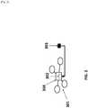
- FIG. 1shows an example of an unmanned aerial vehicle (UAV) that may be associated with an energy provision station.
- UAVunmanned aerial vehicle
- the UAVmay land on or take off from the energy provision station.
- An energy provision system 100may be provided in accordance with an embodiment of the invention.
- the energy provision systemmay comprise a UAV 101 and an energy provision station 102.
- the UAVmay be adapted to identify and communicate with the energy provision station.
- any description herein of a UAV 101may apply to any type of movable object.
- the description of a UAVmay apply to any type of unmanned movable object (e.g., which may traverse the air, land, water, or space).
- the UAVmay be capable of responding to commands from a remote controller.
- the remote controllermay be not connected to the UAV, the remote controller may communicate with the UAV wirelessly from a distance.
- the UAVmay be capable of operating autonomously or semi-autonomously.
- the UAVmay be capable of following a set of pre-programmed instructions.
- the UAVmay operate semi-autonomously by responding to one or more commands from a remote controller while otherwise operating autonomously. For instance, one or more commands from a remote controller may initiate a sequence of autonomous or semi-autonomous actions by the UAV in accordance with one or more parameters.
- the UAV 101may be an aerial vehicle.
- the UAVmay have one or more propulsion units that may permit the UAV to move about in the air.
- the one or more propulsion unitsmay enable the UAV to move about one or more, two or more, three or more, four or more, five or more, six or more degrees of freedom.
- the UAVmay be able to rotate about one, two, three or more axes of rotation.
- the axes of rotationmay be orthogonal to one another.
- the axes of rotationmay remain orthogonal to one another throughout the course of the UAV's flight.
- the axes of rotationmay include a pitch axis, roll axis, and/or yaw axis.
- the UAVmay be able to move along one or more dimensions.
- the UAVmay be able to move upwards due to the lift generated by one or more rotors.
- the UAVmay be capable of moving along a Z axis (which may be up relative to the UAV orientation), an X axis, and/or a Y axis (which may be lateral).
- the UAVmay be capable of moving along one, two, or three axes that may be orthogonal to one another.
- the UAV 101may be a rotorcraft.
- the UAVmay be a multi-rotor craft that may include a plurality of rotors.
- the plurality or rotorsmay be capable of rotating to generate lift for the UAV.
- the rotorsmay be propulsion units that may enable the UAV to move about freely through the air.
- the rotorsmay rotate at the same rate and/or may generate the same amount of lift or thrust.
- the rotorsmay optionally rotate at varying rates, which may generate different amounts of lift or thrust and/or permit the UAV to rotate.
- one, two, three, four, five, six, seven, eight, nine, ten, or more rotorsmay be provided on a UAV.
- the rotorsmay be arranged so that their axes of rotation are parallel to one another. In some instances, the rotors may have axes of rotation that are at any angle relative to one another, which may affect the motion of the UAV.
- FIG. 2shows a detailed view of a possible embodiment of an energy provision system comprising the UAV 201 and the energy provision station 202.
- the UAV 201 shown in FIG. 2is an example of a UAV that can be part of the energy provision system.
- the UAV shownmay have a plurality of rotors 203.
- the rotors 203may connect to the body of the UAV 204 which may comprise a control unit, inertial measuring unit (IMU), processor, battery, power source, and/or other sensors.
- the rotorsmay be connected to the body via one or more arms or extensions that may branch from a central portion of the body.
- one or more armsmay extend radially from a central body of the UAV, and may have rotors at or near the ends of the arms.
- the UAVmay be situated on a surface of the energy provision station by a landing stand 205.
- the landing standmay be configured to support the weight of the UAV when the UAV is not airborne.
- the landing standmay include one or more extension members that may extend from the UAV.
- the extension members of the landing standmay extend from one or more arms of the UAV, or from a central body of the UAV.
- the extension members of the landing standmay extend from beneath one or more rotors, or near one or more rotors.
- the extension membersmay extend substantially vertically.
- the energy provision station 202may be a battery station.
- the energy provision stationmay be a ground station.
- the energy provision stationmay be a battery changing station or battery exchange station.
- the energy provision stationmay be a battery recharging station.
- the energy provision stationmay be portable.
- the energy provision stationmay be capable of being carried by a human.
- the energy provision stationmay be capable of being lifted by a human in one or two hands.
- the energy provision stationmay be reconfigurable or folded in on itself to become more portable.
- the energy provision station 202may have a landing area for a UAV 206. Any surface of the energy provision station may be adapted to comprise the landing area. For example, a top surface of the energy provision station may form a landing area.
- one or more platformsmay be provided as a landing area for the UAV. The platforms may or may not include any sides, ceilings, or covers.
- the energy provision station 202may further comprise a battery storage system.
- the battery storage systemmay be configured to store one or more batteries.
- the battery storage systemmay charge the one or more stored batteries.
- the battery storage system 207is shown below the landing area 206.
- Another component of an energy provision stationmay be a mechanism configured to remove a battery from a UAV and to replace the removed battery with a fully or partially charged battery from the battery storage system.
- a vertical position and/or velocity of the UAVmay be controlled by maintaining and/or adjusting output to one or more propulsion units of the UAV. For example, increasing the speed of rotation of one or more rotors of the UAV may aid in causing the UAV to increase in altitude or increase in altitude at a faster rate. Increasing the speed of rotation of the one or more rotors may increase the thrust of the rotors. Decreasing the speed of rotation of one or more rotors of the UAV may aid in causing the UAV to decrease in altitude or decrease in altitude at a faster rate. Decreasing the speed of rotation of the one or more rotors may decrease the thrust of the one or more rotors.
- the outputWhen a UAV is taking off, such as from an energy provision station, the output may be provided to the propulsion units may be increased from its previous landed state. When the UAV is landing, such as on a vehicle, the output provided to the propulsion units may be decreased from its previous flight state.
- the UAVmay be configured to take off and/or land on an energy provision station in a substantially vertical manner.
- a lateral position and/or velocity of the UAVmay be controlled by maintaining and/ or adjusting output to one or more propulsion units of the UAV.
- the altitude of the UAV and the speed of rotation of one or more rotors of the UAVmay affect the lateral movement of the UAV.
- the UAVmay be tilted in a particular direction to move in that direction, and the speed of the rotors of the UAV may affect the speed of the lateral movement and/or trajectory of movement.
- Lateral position and/or velocity of the UAVmay be controlled by varying or maintaining the speed of rotation of one or more rotors of the UAV.
- the UAV 101may be of small dimensions.
- the UAVmay be capable of being lifted and/or carried by a human.
- the UAVmay be capable of being carried by a human in one hand.
- the energy provision stationmay have a landing area configured to provide a space for the UAV to land.
- the UAV dimensionsmay optionally not exceed the width of the energy provision station landing area.
- the UAV dimensionsmay optionally not exceed the length of the energy provision station landing area.
- the UAV 101may have a greatest dimension (e.g., length, width, height, diagonal, diameter) of no more than 100 cm.
- the greatest dimensionmay be less than or equal to 1 mm, 5 mm, 1 cm, 3 cm, 5 cm, 10 cm, 12 cm, 15 cm, 20 cm, 25 cm, 30 cm, 35 cm, 40 cm, 45 cm, 50 cm, 55 cm, 60 cm, 65 cm, 70 cm, 75 cm, 80 cm, 85 cm, 90 cm, 95 cm, 100 cm, 110 cm, 120 cm, 130 cm, 140 cm, 150 cm, 160 cm, 170 cm, 180 cm, 190 cm, 200 cm, 220 cm, 250 cm, or 300 cm.
- the greatest dimension of the UAVmay be greater than or equal to any of the values described herein.
- the UAVmay have a greatest dimension falling within a range between any two of the values described herein.
- the UAV 101may be lightweight.
- the UAVmay weigh less than or equal to 1 mg, 5 mg, 10 mg, 50 mg, 100 mg, 500 mg, 1 g, 2 g, 3 g, 5 g, 7 g, 10 g, 12 g, 15 g, 20 g, 25 g, 30 g, 35 g, 40 g, 45 g, 50 g, 60 g, 70 g, 80 g, 90 g, 100 g, 120 g, 150 g, 200 g, 250 g, 300 g, 350 g, 400 g, 450 g, 500 g, 600 g, 700 g, 800 g, 900 g, 1 kg, 1.1 kg, 1.2 kg, 1.3 kg, 1.4 kg, 1.5 kg, 1.7 kg, 2 kg, 2.2 kg, 2.5 kg, 3 kg, 3.5 kg, 4 kg, 4.5 kg, 5 kg, 5.5 kg, 6 kg, 6.5 kg, 7 kg, 7.5 kg, 8 kg, 8.5 kg, 9 kg,
- One or more components of the UAVmay be powered by a battery.
- the entire UAVmay be powered by a battery or only a propulsion unit, controller, communication unit, Inertial Measure Unit (IMU), and/or other sensors may be powered by a battery.
- Batterycan refer to a single battery or a pack of two or more batteries.
- An example of a batterymay include a lithium ion battery, alkaline battery, nickel cadmium battery, lead acid battery, or nickel metal hydride battery.
- the batterymay be a disposable or a rechargeable battery. The life time of the battery (i.e.
- the life timemay be at least 1 min, 5 min, 10 min, 15 min, 30 min, 45 min, 1 hr, 2 hrs, 3 hrs, 4hrs, 5 hrs, or 10 hrs.
- the battery lifemay have a duration greater than or equal to any of the values described herein.
- the battery lifemay have a duration falling within a range between any two of the values described herein.
- a batterymay be coupled to the UAV to provide power to the UAV by an electrical connection. Any description herein of a battery may apply to one or more batteries. Any description of a battery may apply to a battery pack, and vice versa, where a battery pack may include one or more batteries. Batteries may be connected in series, in parallel, or any combination thereof. An electrical connection between a UAV and a battery or a component of a UAV and a battery may be provided. An electrical contact of a battery may contact an electrical contact of the UAV.
- the UAVmay have recessed region on its body to house the battery.
- FIG. 3shows an example of a UAV 301 with a recessed region 302 configured to house a battery 303 in the body of the UAV 304.
- the recessed regionmay have equal or non-equal length, width and depth. Possible values for the length, width, and depth of the recessed region may be at least 1 mm, 5 mm, 1 cm, 3 cm, 5 cm, 10 cm, 12 cm, 15 cm, 20 cm, 25 cm, 30 cm, 35 cm, 40 cm, 45 cm, 50 cm, 55 cm, 60 cm, 65 cm, 70 cm, 75 cm, 80 cm, 85 cm, 90 cm, 95 cm, or 100 cm.
- the recessed regionmay be configured to hold one or more batteries.
- the recessed regionmay contain electrical contacts to connect the battery to the UAV power system. Additionally the recessed region may comprise electrical connections to communicate with a sensor which may dynamically read and record the remaining charge on the battery.
- the recessed regionmay include one or more electrical contacts that may be in electrical contact with the battery onboard the UAV. The electrical contacts may be coupled to the battery while it is inside of the recessed region, if the battery is removed the contact may be disconnected from the battery.
- the method of swapping of a battery on a UAV by an energy provision stationmay include the steps of landing the UAV at the energy provision station, removing an on-board battery from the UAV using a component of the energy provision station, exchanging the on-board battery for another battery provided at the energy provision station, coupling the other battery to the UAV, and causing the UAV to take off of from the energy provision station. All or any one of these steps may be fully or partially automated.
- the steps described in FIG. 4may occur in the order shown, or the steps may occur out of order.
- the method of battery exchangemay include all of the steps listed or a subset of the steps listed.
- the UAVmay land on a landing area on the energy provision station 401.
- the depleted batterymay be removed by a mechanism on the energy provision station.
- the energy provision stationmay employ a robotic arm to remove the depleted battery from the UAV 402.
- the depleted batterymay be stored in a battery storage unit.
- the battery storage unitmay comprise a container for the battery, the container may include electrical connections configured to provide charge to the battery.
- An example of a battery storage areamay be a carousel on board the energy provision station 403.
- the carouselmay be configured such that it may rotate to carry away the depleted battery and place a charged battery in line with a mechanism configured to install the charged battery on the UAV.
- a mechanismmay be a robotic arm 404.
- the robot arm that transports the charged battery to the UAVmay be the same robotic arm that removes the depleted battery from the UAV.
- the robotic armAfter rotation of the carousel, the robotic arm may install the charged battery in the UAV 405.
- the final stepmay be for the UAV to take off from the landing area with a fully charged battery on board 406.
- the UAVmay communicate with an energy provision station.
- the UAVmay transmit information to the energy provision station regarding the state of the battery on board the UAV, the current flight conditions, time or distance remaining on current mission, distance to the next energy provision station, battery specifications, state of battery charge (e.g. remaining power estimate), battery temperature, UAV specifications, or flight plan (e.g. estimated arrival at the next energy provision station and/or estimated time of arrival at final destination).
- the UAVmay also communicate information to the energy provision station describing the state of the UAV.
- the UAVmay communicate information describing system failures or descriptions of damaged parts (e.g. broken propeller) to the energy provision station.
- the UAVmay carry a payload.
- the UAVmay communicate the weight of the pay load. Additionally the UAV may communicate to the energy provision station when in the flight plan the UAV plans to load or unload the payload.
- the energy provision stationmay communicate information to the UAV.
- the energy provision stationmay inform the UAV as to whether or not it is available to provide the UAV with a charged battery. For example, the energy provision station may be depleted of charged batteries or the energy provision station may be occupied by another UAV, in these instances the energy provision station may instruct the UAV to continue on to the next closest energy provision station. In another case the energy provision station may instruct the UAV to continue to the next closest energy provision station in the case of adverse weather conditions (e.g. wind, rain, snow) or a mechanical or electrical failure on the energy provision station.
- the energy provision stationmay transmit updated route instruction to the UAV to direct the UAV to the next energy provision station. Alternatively, when the energy provision station is available for charging, the energy provision station may instruct the UAV to land on the station.
- the UAVmay be directed to land at the energy provision station.
- An instruction to land on the energy provisionmay be transmitted by the energy provision station.
- the UAVmay be directed to land at the energy provision station.
- UAV operating parameterssuch as expected rate of energy consumption, or current rate of energy consumption, may be taken into account. For example, a UAV may be flying in a relatively 'low power' mode where one or more of the sensors are not in operation, but it may be anticipated that the UAV may employ more of the sensors later in flight.
- the anticipated increased rate of energy consumptionmay affect the anticipated rate of battery charge depletion, which may be taken into account when determining whether the UAV needs to land at the energy provision station.
- the UAVmay be directed to land at the energy provision station if the state of charge of the battery falls beneath a predetermined threshold.
- the UAVmay be instructed to land on the energy provision station if a mechanical or electrically system on board the UAV is in need of repair (e.g. broken propeller, short in electrical component).
- Landing on an energy provision stationmay be predetermined by a UAVs flight plan. For example a UAV instructed to travel from point A to point B may have a planned stop at an energy provision station halfway between point A and point B. The decision to land at an energy provision station as part of the flight plan may be contingent on the energy provision station being unoccupied. For example, energy provision station halfway between point A and point B is occupied by another UAV the UAV may alter its flight plan to continue on to the next energy provision station as long as the power remaining on the battery is sufficient to reach the next energy provision station.
- the UAVsmay be entered into a queue.
- the UAVs in the queuemay wait for access to the energy provision station.
- the UAVs in the queuemay be ordered such that UAVs in urgent need of aid from the energy provision station (e.g. those with mechanical failures and/or critically low batteries) may be attended to before UAVs in less need of aid from the energy provisions station.
- the UAVs in the queuemay be ranked by layers or they may be ranked based on a system of weighing various factors.
- the primary layermay be the mechanical or electrical status of the UAV
- the secondary layermay be the energy remaining on the UAV's battery
- the tertiary layermay be how long the UAV has been waiting for aid from the energy provision station.
- the layersmay be used to rank the UAVs in the queue.
- factorssuch as the mechanical or electrical status of components of the UAV, the power storage remaining on the battery of the UAV, and how long the UAV has been waiting in the queue may be considered.
- a weighted average (e.g. a score) of the aforementioned factorsmay be used to determine a UAVs location in the queue.
- An interaction between a UAV and an energy provision stationmay follow the procedure outline in FIG. 21 .
- the interactionmay include all the steps shown in FIG. 21 or a subset of these steps, the steps may occur in the order shown or in an alternate order.
- the UAVmay detect the energy provision station 2101.
- the detection of the energy provision station by the UAVmay be in response to a known GPS signal indicating the location of the energy provision station, a visual detection, or an audio detection.
- the UAVmay exchange information with the energy provision station 2102, for example the UAV may communicate information regarding the state of the UAV and/or the battery.
- the energy provision stationmay provide the UAV with information regarding the state of the energy provision station.
- the UAVmay determine if it should land on the energy provision station or continue on its flight path 2103. If the UAV decides to land on the energy provision station it may enter a queue of UAVs waiting to land on the energy provision station 2104. When the UAV is the first UAV in the queue and the energy provision station is unoccupied by another UAV the UAV may land on the energy provision station 2105.
- the UAVmay identify an energy provision station landing area by sensing a marking, for example a marking may be a raised pattern, a recessed pattern, an image, a symbol, a decal, a 1-D, 2-D, or 3-D barcode, a QR code, or lights visible on the energy provision station landing area.
- the markingmay indicate that the energy provision station has charged batteries available.
- the markingmay be a light or pattern of lights, the lights may be turned on only when the energy provision station has charged batteries available.
- the UAVmay take off and land on the energy provision station landing area vertically.
- the landing areamay comprise recessed mating features to guide the UAV during landing.
- the mating featuresmay decrease the need for accuracy when landing the UAV on the landing area.
- the recessed featuresmay be configured to mate with a wide variety of UAVs, alternatively the mating features may be specific to a single UAV manufacturer, single UAV fleet, or one particular UAV.
- Communication between the UAV and the energy provision stationmay be used to get the UAV to the general location of the energy provision station. Communication between the UAV and the energy provision station may occur wirelessly.
- the UAVmay employ GPS or other locating software to locate the energy provision station. The GPS or other location techniques can be used to get the UAV to the vicinity of the energy provision station.
- the wireless communicationsmay get the UAV within range to sense one or more portions of the energy provision stations. For instance, the UAV may be brought into a line-of-sight of the energy provision station.
- the landing area marker or markersmay aid in further pinpointing the location of the energy provision station.
- the markermay serve as a confirmation of the energy provision station on which the UAV may land.
- the markersmay also differentiate the energy provision station or a landing area of an energy provision station from other objects or regions.
- the markermay be useful for indicating a landing position of the UAV on the energy provision station.
- the markermay be used as a fiducial marker, which may aid the UAV in navigating to a proper landing position on the energy provision station.
- multiple markersmay be provided which may aid the UAV in landing in a desired position.
- itmay also be desirable for a UAV to have a particular orientation when docking with the energy provision station.
- the markermay include an asymmetric image or code that may be discernible by the UAV.
- the fiducialmay be indicative of the orientation of the energy provision station relative to the UAV. Thus, the UAV may be able to orient itself properly when landing on the energy provision station.
- the markermay also be indicative of the distance of the energy provision station relative to the UAV. This may be used separate from or in combination with one or more other sensors of the UAV to determine the altitude of the UAV. For example, if the size of the fiducial marker is known, the distance from the UAV to the marker may be gauged depending on the size of the marker showing up in the sensors of the UAV.
- the markermay be provided at a particular location relative to a desired landing spot of the UAV on the energy provision station. This may be at a particular location relative to a desired landing spot on a landing area of an energy provision station.
- the UAVmay be capable of landing on the landing area with great precision.
- the markermay help guide the UAV to the exact desired spot. For instance, the marker may be located 10 cm in front of the center of the desired landing point of the UAV.
- the UAVmay use the marker to guide the UAV to the exact landing spot.
- multiple markersmay be provided. The desired landing spot may fall between the multiple markers.
- the UAVmay use the markers to help orient the UAV and/or position its landing between the markers. Distance between the markers may aid the UAV in gaging the distance of the UAV to the landing area.
- the markermay be provided anywhere on the energy provision station or landing area.
- the markermay be placed in a location such that it is easily discernable from above.
- the markermay be provided on an exterior surface of the energy provision station.
- the markermay include a wireless signal being emitted by an energy provision station. The origin of the signal may be from outside the energy provision station or inside the energy provision station. Alternatively the energy provision station may emit IR and/or UV light, radio, or audio signals.
- the markermay be positioned near where the UAV may dock with the energy provision station.
- the markermay be positioned less than about 100 cm, 90 cm, 80 cm, 75 cm, 70 cm, 65 cm, 60 cm, 55 cm, 50 cm, 45 cm, 40 cm, 35 cm, 30 cm, 25 cm, 20 cm, 15 cm, 12 cm, 10 cm, 8 cm, 7 cm, 6 cm, 5 cm, 4 cm, 3 cm, 2 cm, or 1 cm from where the UAV lands on the energy provision station.
- Data pertaining to the detected markermay be provided to one or more processors.
- the processorsmay be on board the UAV. Based on the detected information about the detected marker, the processors may, individually or collectively, generate a command signal.
- the command signalmay drive the propulsion units of the UAV.
- the propulsion unitsmay be driven to cause the UAV to land on the energy provision station with the detected marker, when the detected marker is determined to belong to the energy provision station.
- the detected markermay indicate the state of charge of the stored batteries at the energy provision station. For example if the energy provision station has a fully charged battery available the detected marker may result in a command from the processor to land the UAV.
- a UAVmay be able to land in an autonomous or semi-autonomous fashion in response to a detected marker.
- the UAVmay be capable of landing without receiving any commands or manual input from a user.
- sensors on board the UAVmay be used to detect the marker, and processing may occur on-board the UAV.
- the UAVmay be capable of landing itself on the energy provision station without requiring further guidance or information from the energy provision station once the UAV has confirmed that the marker belongs to the energy provision station.
- An energy provision stationmay include a marker, and one or more coupling connection components.
- the energy provision stationmay send information about its location to a UAV.
- the energy provision stationmay have a location unit capable of determining positional information.
- An energy provision stationmay receive information from the UAV about the location of the UAV and the state of the battery on board the UAV. For example, coordinate information, such as GPS coordinates, for the UAV may be provided to the energy provision station. In another example the UAV may communicate the remaining charge percentage of the battery currently in use on the UAV.
- the energy provision stationmay have a communication unit capable of communicating with the UAV.
- the energy provision stationmay have a processor capable of identifying and/or calculating a location of the UAV.
- the energy provision stationmay have a processor capable of identifying and/or calculating a location of the next nearest battery exchange station. For example a UAV may communicate to an energy provision station that the battery currently on board the UAV has a remaining charge percentage of 18%, the processor at the energy provision station may determine the distance to the next battery exchange station in the UAV's flight path to determine if the UAV should stop for recharging or continue to the next energy provision station.
- FIG. 5shows a possible embodiment of an energy provision station.
- the energy provision stationmay have three basic components: a battery replacement member 501, a UAV landing area 502, and a battery storage unit 503.
- the battery replacement membermay be a mechanical arm 501 that may be configured to remove a battery from a UAV and/or to place a charged battery in the UAV.
- the mechanical armmay both remove the battery from the UAV and place a charged battery in the UAV.
- different mechanical componentsmay be used to remove the battery form the UAV and to place a charged battery in the UAV.
- the mechanical armmay have at least 1, 2, 3, 4, 5, or 6 degrees of freedom.
- the mechanical armmay move autonomously or semi autonomously.
- the UAV landing 502 areamay comprise markers that may be uniquely recognized by an approaching UAV.
- the landing areamay comprise a passive landing guide 504.
- the passive landing guidesmay be configured to interact with a component of a UAV as it lands to guide the UAV to a final resting position.
- the UAVmay include a landing stand that may fit into a passive landing guide and be guided to the final resting position.
- the UAVmay include a surface upon which the UAV may land. The UAV may rest on the surface, or all or a majority of the weight of the UAV may be borne by the passive landing guides.
- the battery storage unit 503may store a plurality of batteries.
- the battery storage unitmay simultaneously store and charge the stored batteries.
- the battery storage unitmay move the batteries relative to each other.
- the battery storage unitmay move the batteries relative to the UAV landing area and/or a UAV on the landing area. Multiple batteries may be moved simultaneously using the battery storage unit.
- a fully charged batterymay be in a location such that the mechanical arm 501 may install the battery on the UAV.
- a mechanical armmay bring a depleted battery from a UAV to a particular location relative to the battery storage unit.
- the battery storage unitmay accept the depleted battery.
- the battery storage unitmay cause movement of the batteries so that a different battery (e.g., fully charged battery) is moved to the location where the depleted battery was accepted.
- the mechanical armmay receive the different battery.
- the movementmay include rotation of the battery storage unit about an axis.
- the UAV landing area of the energy provision stationmay be configured to comprise a passive landing guide.
- the UAVmay have at least one protruding feature which may mate with a corresponding cavity on the landing area of the energy provision station.
- the UAVmay have four round conical stoppers which may fit inside of four round conical indentations on the landing area.
- the protruding featuremay be a launch stand configured to bear a weight of the UAV.
- FIG. 6shows an example of a UAV 601 landing on an energy provision station 602 such that the conical stoppers 603 mate with the conical indentations 604 on the landing area.
- the stopper and the indentationmay comprise a variety of other mating shapes.
- the stoppermay be made from rubber, plastic, metal, wood, or composite.
- the stoppermay have a height and width of less than or equal to 1 mm, 5 mm, 1 cm, 3 cm, 5 cm, 10 cm, 12 cm, 15 cm, 20 cm, 25 cm, 30 cm, 35 cm, 40 cm, 45 cm, 50 cm, 55 cm, 60 cm, 65 cm, 70 cm, 75 cm, 80 cm, 85 cm, 90 cm, 95 cm, or 100 cm.
- the indentationsmay have corresponding dimensions such that they are adapted to fit the stopper.
- the UAVmay comprise a protrusion that does not identically mate with an indentation on the landing area.
- the UAVmay have a feature protruding from the bottom of the UAV designed such that it is smaller than the indentation on the landing area.
- the protruding feature on the bottom of the UAVmay fit into the indentation.
- the UAVmay have a protruding rod and the landing area may have a conical indentation. Upon landing, the protruding rod may be funneled into the bottom of the conical indentation.
- FIG. 7shows a detailed side (left) and top (right) view of a possible embodiment of the landing area 701 with a docked UAV 702 showing a protruding rod fitting inside of a conical indentation 703.
- the protruding rodmay be a landing stand of the UAV.
- the protruding rodsmay bear the weight of the UAV while the UAV is resting on the landing area.
- the indentationsmay bear the weight of the protruding rods and/or the UAV while the UAV is resting on the landing area.
- the passive landing guidemay reduce the need for high precision control of the UAV landing procedure.
- the passive landing guidemay be configured such that the UAV may corrected if it approaches the station in such a way that it is off set from the desired landing location.
- the passive landing guidemay bring the UAV into the desired location with the aid of gravity.
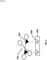
- FIG. 8shows an example of how the passive landing guide may correct the UAV if it approaches the landing location with an off set.
- the UAVapproaches the landing guide off set to the right (1).
- the UAVpartially mates with the passive landing guide, after contact with the landing guide the UAV may slide downward into the correct location (2). This process of correcting the UAV to the correct landing location may rely on gravity and may not introduce a need for a moving part or additional mechanism.
- the UAVmay locate the energy provision station using real time kinematics (RTK).
- RTK location methodsmay require both the UAV and the energy provision station to emit a satellite signal, for example a GPS signal.
- RTKmay allow the UAV to locate the correct docking location on the energy provision station with accuracy within 10 cm, 9 cm, 8 cm, 7 cm, 6 cm, 5 cm, 4 cm, 3 cm, 2 cm, 1 cm, or less than 1 cm.
- the energy provision stationmay comprise a battery storage system.
- the battery storage systemmay be a carousel.
- the batteries in the battery storage systemmay be fully charged, partially charged, or depleted of charge.
- the batteriesmay be connected to a source of electrical power to restore them from a depleted or partially charged state to a state of full charge.
- the batteriesmay be identical in size, shape, and battery type (e.g. lithium ion, nickel cadmium). Alternatively, different battery sizes, shapes or types may be accommodated.
- the battery storage systemmay be configured to store at least 2, 3, 4, 5, 6, 7, 8, 9, 10, 15, 20, 25, 30, 35, 40, 45, or 50 batteries. In some embodiments, the battery system may store less than any of the number of batteries described.
- the battery systemmay store a number of batteries falling within a range between any two of the values described.
- the battery storage systemmay comprise individual ports for each battery.
- the portsmay be movable relative to each other. Multiple ports may move simultaneously.
- the portsmay rotate about an axis clockwise, counterclockwise, or in both rotational directions.
- the axis of rotationmay be horizontally oriented (e.g., parallel to an underlying surface or ground, perpendicular to the direction of gravity), or vertically oriented (e.g., perpendicular to an underlying surface or ground, parallel to the direction of gravity).
- the portsmay translate in any direction. Optionally, they may translate and rotate simultaneously.
- the portsmay have electrical connections which may connect to the processor to meter the charge available on the battery or they may connect to an electricity source to charge the battery.
- the electricity sourcemay be on board or off board the energy provision station.
- the electricity sourcemay be an electric generator, a rechargeable battery, a disposable battery, or a connection to a distributed power line.
- the portsmay charge the batteries inductively (wirelessly).
- Multiple charging interfacesmay be accommodated by the energy provision station such that the station can charge a variety of battery types and voltages.
- the energy provision stationmay be permanently installed or it may be temporary. In the case of a temporary energy provision station, the station may be configured to be portable and may be carried away by a user.
- the stored batteriesmay move relative to each other.
- the batteriesmay move relative to each other in a carousel.
- FIG. 9shows an example of a possible battery carousel 901 for use in the battery storage system.
- the carousel shown in FIG. 9can hold 8 batteries 902.
- a carouselmay be chosen such that it can hold at least 4, 5, 6, 7, 8, 9, 10, 15, 20, 25, 30, 35, 40, 45, or 50 batteries.
- the carouselmay be configured to hold fewer batteries than values described herein or the carousel may be configured to hold a number of batteries within a range between any two of the values described herein.
- the batteries in the carouselmay be identical in size, shape, voltage, and composition. Each battery may be stored in a compartment 903.
- the batterymay slide in and out of the compartment during installation and removal from a UAV. For instance, the battery may slide and out laterally via a side opening of the compartment. The battery may be able to lock into the compartment during storage.
- a batterymay be charged on board the UAV or a battery may be charged in the storage compartment in the battery storage system.
- the battery storage compartmentmay be configured to provide electrical charge to the battery through electrical contacts.
- FIG. 10shows an example of a possible battery storage compartment 1001 with electrical contacts configured 1002 to provide charge to a battery.
- the electrical contactsmay be connected to a power source 1003 off board the battery.
- the batterymay be simultaneously connected to a meter to determine when the battery charge is complete.
- the containermay provide only enough electrical power to charge or partially charge the stored battery.
- the battery storage compartmentmay be part of a carousel or other battery storage unit.
- the battery storage compartmentmay be movable relative to other portions of an energy provision station.
- the battery carousel 901may rotate about a shaft 904.
- the carouselmay rotate counter-clockwise or clockwise.
- the carouselmay be able to rotate in either both directions or only one direction.
- the rotationmay be driven by an actuator, such as a motor.
- the actuatormay receive a command signal from a controller on-board or off-board the energy provision station that controls movement of the battery storage system.
- the carouselmay be configured perpendicular to the base of the energy provision station 905.
- the length of the shaftmay be parallel to the base of the energy provision station.
- the carouselmay be oriented parallel to the base of the base of the energy provision station or at any other angle relative to the base of the energy provision station.
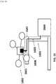
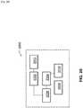
- FIG. 11shows a possible embodiment of the complete energy provision station.
- FIG. 11shows that the landing area 1101 may be placed on top of the carousel 1102.
- the battery carouselmay be partially or completely enclosed by a housing.
- the battery storage systemmay be driven by an actuator to rotate.
- the battery storage systemmay include a steering lock, so that the battery storage can be locked when needed to prevent it from rotating and fix it at the desired position.
- the steering lockmay be located at the bottom of the carousel, the top, or along the sides.
- the energy provision stationmay comprise a mechanism configured to move the batteries.
- the mechanismmay be an automated battery replacement member.
- the mechanismmay be a robotic arm, actuator, or a pulley.
- the mechanismmay be a mechanical elevator.
- the mechanism configured to move the batteriesmay be a robotic arm.
- the robotic armmay have at least 2 degrees of freedom.
- a robotic arm having 2 degrees of freedommay be able to move (1) horizontally and (2) vertically.
- the up and down motionmay be achieved by a linear actuator, or any other type of actuator.
- the horizontal motionmay be achieved by a rack and pinion mechanism driven by an actuator.
- the horizontal motionmay be a linear motion.
- the horizontal actuatormay be installed on a vertical motion actuator such that the robotic arm may vertically and then horizontally.
- the robotic armmay permit a battery to move vertically and/or horizontally without causing any rotation of the battery.
- the batterymay be translated without being rotated by the robotic arm.
- the robotic armmay permit rotation or change in orientation of the
- the mechanism configured to move the batteriesmay comprise an end member adapted to attach to the battery to be removed from the UAV.
- the end membermay be a magnet, a hook, or a suction device.
- the end membermay be a clamp.
- the clampmay be installed on the forward and back module such that the robotic arm may move forward or back and then clamp or release a battery.
- the clamping motionmay be driven by a steering gear and linkage system.
- the clampmay attach to the battery by compressing the battery between two sides of the clamp with sufficient pressure to hold the battery, alternatively the battery and the clamp may comprise complimentary mating features.
- An example of a complimentary mating featuremay be a peg and a hole. Similar mating features may be used to hold the batteries in the battery storage unit.
- FIG. 12shows a schematic of a possible robotic arm.
- the robotic armmay be raised from the base of the energy provision station by a post 1201.
- the robotic armmay be configured to move up and down along the post.
- the robotic armmay move up and down autonomously or semi autonomously.
- the robotic armmay be attached to the post via a second rail 1202 on which it may be configured to move forward and back.
- the robotic armmay move forward and back autonomously or semi autonomously.
- the third feature of the robotic armmay be a terminal clamp 1203.
- the terminal clampmay have a c shaped opening which may open towards the recessed battery of a docked UAV.
- the terminal clampmay open and close, it may be able to attach to a battery.
- FIG. 13shows a detailed view of an illustrative example of a robotic arm.
- the example shown in FIG. 13depicts a clamp 1301 mounted on a rack and pinion mechanism 1302.
- the clampmay be oriented horizontally, so that ends of the clamp grid onto the sides of the battery.
- the clampmay include a portion in the rear 1303 that may rotate, thereby causing the ends of the clamp 1304 to move closer together or further apart.
- the rear control portionmay rotate with aid of an actuator, that may operate in response to a command signal from a controller on-board or off-board the energy provision station.
- FIG. 14provides a complete view of the robotic arm including the clamp 1401 mounted on a rack and pinion mechanism 1402.
- the assemblycomprising the clamp and rack and pinion supported on an actuator 1403 configured to move the assembly in a vertical up and down path.
- the entire assemblymay also be rotated clockwise or counterclockwise about a pivot point 1404.
- the pivot pointmay be oriented so that the entire assembly may rotate about a vertical axis of rotation. This may permit the assembly to change orientation.
- the assemblymay rotate about a limited range.
- the robotic armmay not rotate about an axis, it may be fixed rotationally.
- the robotic armmay be employed in the landing of the UAV on the energy provision station instead of or in addition to swapping the battery on board the UAV.
- the UAVmay approach the energy provision station, when the UAV is sufficiently close to the energy provision station the robotic arm may attach to the UAV and place the UAV in a preferred location for battery swapping on board the energy provision station.
- the robotic armmay detect the UAV using a sensor on the robotic arm, for example, the sensor may be a vision sensor, a motion sensor, an audio sensor, or any other sensor configured to detect a UAV in proximity to the robotic arm.
- the robotic armmay attach to the body of the detected UAV, the robotic arm may attach to the UAV using the terminal c shaped clamp. Alternatively the robotic arm may attach to the UAV magnetically, with Velcro, or by achieving positive mating between complimentary mating features on the UAV and the robotic arm.
- the UAVmay turn off its rotors after being sized or grasped by the robotic arm.
- the robotic armmay be specifically configured to seize the UAV from the air to place the UAV on the energy provision station.
- the robotic armmay telescope vertically from the energy provision station such that it may be in the proximity of a UAV approaching the energy provision station.
- the robotic armmay be raised at least 6 inches, 12 inches, 24 inches, 36 inches, 48 inches or 60 inches above the landing area of the energy provision station.
- the robotic armmay be raised above the energy provision station to detect an approaching UAV using a visual sensor. Additionally the robotic arm may rotate about an axis such that it can turn to face an incoming UAV.
- the robotic armmay move vertically, horizontally, and rotationally about a vertical and/or horizontal axis.
- the robotic armmay be raised above the energy provision station after the GPS or RTK system on the energy provision station has detected a UAV in proximity of the energy provision station. Once the robotic arm is raised it may grasp an incoming UAV and then lower to the level of the landing area to place the UAV on the landing area of the energy provision station.
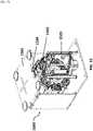
- FIG. 15shows the complete energy provision station assembly including the landing area 1501, battery storage system 1502, and the robotic arm 1503.
- the battery storage systemis below the landing area and the robotic arm is adjacent to the battery storage system and landing area such that it is adapted to access both regions of the energy provision station.
- the robotic armmay move vertically between the UAV landing area and the battery storage system while performing a battery switching procedure.
- a notch or opening 1504may be provided on the UAV landing area that may permit the robotic arm and/or battery to traverse the region between the UAV landing area and the battery storage system.
- the energy provision stationmay provide charge to the battery onboard the UAV.
- the energy provision stationmay provide charge to battery on board the UAV without removing the battery from the recessed region in the body of the UAV. Charge may be provided to the battery on board the UAV from a power source on board or off board the energy provision station.
- FIG. 16shows an example of a battery 1601 on board a UAV 1602 receiving charge from an energy provision station 1603.
- a power source 1604which may be located on board or off board the energy provision station 1603, provides power to the battery 1601 by means of an electrical pathway 1605.
- the electrical pathwaymay include an electrical connection 1606 on the landing area 1607. Alternatively, the electrical pathway may take any path between a battery on-board the UAV and the power source.
- the electrical connection 1606may be recessed in the landing area 1607.
- the electrical connection 1606may be configured to move out of the recession and mate with a battery when instructed by a processor to provide charge to the battery on board the UAV.
- the electrical connectionmay be provided separately from the landing area and may or may not contact the landing area.
- the UAVmay include an electrical contact that may connect with a corresponding electrical contact for a charging apparatus that connects the power source to the battery.
- a UAVmay locate an energy provision station from the air. Upon locating the energy provision station the UAV may communicate with the energy provision station to determine if the UAV should approach and land on the energy provision station to initiate a battery switching procedure.
- a battery life reloading proceduremay initiate when a UAV docks on the landing area of an energy provision station. Reloading battery life on a UAV may include increasing the overall battery state of charge for the UAV.
- Thismay include (1) recharging the existing battery while the battery is on-board the UAV, (2) removing the existing battery from the UAV, recharging the existing battery off-board the UAV, and coupling the existing battery back with the UAV, or (3) removing the existing battery from the UAV, taking a new battery with a higher state of charge, and coupling the new battery with the UAV.
- the UAV docked on the landing areamay communicate with a processor on board the energy provision station.
- the UAVmay communicate remotely with a processor off board the energy provision station.
- the processormay determine the remaining charge on the battery currently in use on the UAV by communicating with a sensor in contact with the battery. The remaining charge on the battery may be sensed by a voltmeter.
- the processormay initiate a response which may include swapping the battery for a fully charged battery from the storage system or charging the current battery.
- the decision to charge or swap the battery onboard the UAVmay be based on a threshold percentage of remaining charge.
- the threshold valuemay be 50%, 40%, 30%, 20%, 10%, or 5% remaining charge.
- the thresholdmay be fixed, or it may be variable as a function of battery age, battery type, flight conditions, ambient temperature, or distance to the next energy provision station. After determining an optimal response the battery swap or charge may take place at the energy provision station.
- the processormay indicate that the UAV may take off from the landing area.
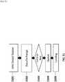
- FIG. 17shows a flow chart outlining a decision process carried out by one or more processors, individually or collectively, when a UAV approaches a landing area.
- the UAVmay communicate with energy provision station.
- the UAVmay communicate variables such as flight time, flight distance, time since last charge, or distance remaining on mission to the energy provision station 1701.
- the processorswhich may be on-board or off-board the energy provision station, may instruct the UAV to land on the energy provision station for further assessment 1702.
- the energy provision stationmay measure the remaining charge on the battery 1703. If the charge is above a pre-determined threshold the energy provision station may provide a charge to the battery currently on board the UAV 1704. If the battery is below a threshold charge percentage the energy provision station may initiate a battery switching procedure 1705 to replace the battery on board the UAV with a fully or partially charged battery from the battery storage system.
- Instruction to swap or charge the battery on board the UAVmay be based entirely on the remaining charge on the battery relative to a pre-determined threshold value or the instructions may be based on one or more other factors.
- the current charge on the batteries in the battery storage systemmay influence the instructions.
- the number of available batteries in the battery storagemay influence the instructions. If no batteries are available, then the battery may be charged on-board, regardless of state of charge. If only a single battery is available, the state of charge of the on-board battery may be compared with the single battery provided by the battery storage system.
- the battery storage battery chargemay affect the instruction to swap or charge the battery such that if the energy provision station has only partially charged batteries in the storage system the processor may give the instruction to charge the battery on board the UAV rather than replacing the battery with a partially charged battery.
- the time required to swap the batterymay be considered in comparison to the time required to charge the battery.
- a decision to swap the battery or charge the batterymay be chosen such that the required time is optimized.
- Other factors that may influence the outcome of the instruction from the processormay include the number of other UAV's detected in the vicinity by the energy provision station, the mission of the UAV landed on the energy provision station, and/ or the current flight conditions (e.g. head wind, tail wind, temperature).
- the battery switching proceduremay employ the robotic arm mechanism.
- the first step in the proceduremay be for the robotic arm to move vertically so that is may be in line with a recessed battery receptacle which may be the location of the battery to be removed from the UAV.
- the robotic armmay move horizontally to approach the battery to be removed from the UAV.
- the clampmay open and close to attach to the battery.
- the armmay retreat horizontally from the UAV and move vertically to be in line with an empty storage receptacle in the battery storage system.
- the robotic armmay place the depleted battery removed from the UAV into the empty storage receptacle in the battery storage system.
- the battery storage systemmay rotate so that a charged or partially charged battery is in line with the robotic arm.
- the robotic armmay repeat the steps used to remove the battery from the UAV in order to remove the charged or partially charged battery from the battery storage system.
- the robotic armmay move vertically to be in line with the UAV recessed battery receptacle.
- the robotic armmay then move horizontally to push the charged or partially charged battery into the recessed battery onboard the UAV.
- the robotic armmay then release the clamp on the battery and retreat from the UAV. After the robotic arm retreats the UAV may take off vertically from the landing area and continue its mission.
- any description herein of an aerial vehiclesuch as a UAV, may apply to and be used for any movable object.
- Any description herein of an aerial vehiclemay apply specifically to UAVs.
- a movable object of the present inventioncan be configured to move within any suitable environment, such as in air (e.g., a fixed-wing aircraft, a rotary-wing aircraft, or an aircraft having neither fixed wings nor rotary wings), in water (e.g., a ship or a submarine), on ground (e.g., a motor vehicle, such as a car, truck, bus, van, motorcycle, bicycle; a movable structure or frame such as a stick, fishing pole; or a train), under the ground (e.g., a subway), in space (e.g., a spaceplane, a satellite, or a probe), or any combination of these environments.
- the movable objectcan be a vehicle, such as a vehicle described elsewhere herein.
- the movable objectcan be carried by a living subject, or take off from a living subject, such as a human or an animal.
- Suitable animalscan include avines, canines, felines, equines, bovines, ovines, porcines, delphines, rodents, or insects.
- the movable objectmay be capable of moving freely within the environment with respect to six degrees of freedom (e.g., three degrees of freedom in translation and three degrees of freedom in rotation). Alternatively, the movement of the movable object can be constrained with respect to one or more degrees of freedom, such as by a predetermined path, track, or orientation.
- the movementcan be actuated by any suitable actuation mechanism, such as an engine or a motor.
- the actuation mechanism of the movable objectcan be powered by any suitable energy source, such as electrical energy, magnetic energy, solar energy, wind energy, gravitational energy, chemical energy, nuclear energy, or any suitable combination thereof.
- the movable objectmay be self-propelled via a propulsion system, as described elsewhere herein.
- the propulsion systemmay optionally run on an energy source, such as electrical energy, magnetic energy, solar energy, wind energy, gravitational energy, chemical energy, nuclear energy, or any suitable combination thereof.
- the movable objectmay be carried by a living being.
- the movable objectcan be an aerial vehicle.
- aerial vehiclesmay be fixed-wing aircraft (e.g., airplane, gliders), rotary-wing aircraft (e.g., helicopters, rotorcraft), aircraft having both fixed wings and rotary wings, or aircraft having neither (e.g., blimps, hot air balloons).
- An aerial vehiclecan be self-propelled, such as self-propelled through the air.
- a self-propelled aerial vehiclecan utilize a propulsion system, such as a propulsion system including one or more engines, motors, wheels, axles, magnets, rotors, propellers, blades, nozzles, or any suitable combination thereof.
- the propulsion systemcan be used to enable the movable object to take off from a surface, land on a surface, maintain its current position and/or orientation (e.g., hover), change orientation, and/or change position.
- the movable objectcan be controlled remotely by a user or controlled locally by an occupant within or on the movable object.
- the movable objectmay be controlled remotely via an occupant within a separate vehicle.
- the movable objectis an unmanned movable object, such as a UAV.
- An unmanned movable object, such as a UAVmay not have an occupant onboard the movable object.
- the movable objectcan be controlled by a human or an autonomous control system (e.g., a computer control system), or any suitable combination thereof.
- the movable objectcan be an autonomous or semi-autonomous robot, such as a robot configured with an artificial intelligence.
- the movable objectcan have any suitable size and/or dimensions.
- the movable objectmay be of a size and/or dimensions to have a human occupant within or on the vehicle.
- the movable objectmay be of size and/or dimensions smaller than that capable of having a human occupant within or on the vehicle.
- the movable objectmay be of a size and/or dimensions suitable for being lifted or carried by a human.
- the movable objectmay be larger than a size and/or dimensions suitable for being lifted or carried by a human.
- the movable objectmay have a maximum dimension (e.g., length, width, height, diameter, diagonal) of less than or equal to about: 2 cm, 5 cm, 10 cm, 50 cm, 1 m, 2 m, 5 m, or 10 m.
- the maximum dimensionmay be greater than or equal to about: 2 cm, 5 cm, 10 cm, 50 cm, 1 m, 2 m, 5 m, or 10 m.
- the distance between shafts of opposite rotors of the movable objectmay be less than or equal to about: 2 cm, 5 cm, 10 cm, 50 cm, 1 m, 2 m, 5 m, or 10 m.
- the distance between shafts of opposite rotorsmay be greater than or equal to about: 2 cm, 5 cm, 10 cm, 50 cm, 1 m, 2 m, 5 m, or 10 m.
- the movable objectmay have a volume of less than 100 cm x 100 cm x 100 cm, less than 50 cm x 50 cm x 30 cm, or less than 5 cm x 5 cm x 3 cm.
- the total volume of the movable objectmay be less than or equal to about: 1 cm 3 , 2 cm 3 , 5 cm 3 , 10 cm 3 , 20 cm 3 , 30 cm 3 , 40 cm 3 , 50 cm 3 , 60 cm 3 , 70 cm 3 , 80 cm 3 , 90 cm 3 , 100 cm 3 , 150 cm 3 , 200 cm 3 , 300 cm 3 , 500 cm 3 , 750 cm 3 , 1000 cm 3 , 5000 cm 3 , 10,000 cm 3 , 100,000 cm 3 3, 1 m 3 , or 10 m 3 .
- the total volume of the movable objectmay be greater than or equal to about: 1 cm 3 , 2 cm 3 , 5 cm 3 , 10 cm 3 , 20 cm 3 , 30 cm 3 , 40 cm 3 , 50 cm 3 , 60 cm 3 , 70 cm 3 , 80 cm 3 , 90 cm 3 , 100 cm 3 , 150 cm 3 , 200 cm 3 , 300 cm 3 , 500 cm 3 , 750 cm 3 , 1000 cm 3 , 5000 cm 3 , 10,000 cm 3 , 100,000 cm 3 , 1 m 3 , or 10 m 3 .
- the movable objectmay have a footprint (which may refer to the lateral cross-sectional area encompassed by the movable object) less than or equal to about: 32,000 cm 2 , 20,000 cm 2 , 10,000 cm 2 , 1,000 cm 2 , 500 cm 2 , 100 cm 2 , 50 cm 2 , 10 cm 2 , or 5 cm 2 .
- the footprintmay be greater than or equal to about: 32,000 cm 2 , 20,000 cm 2 , 10,000 cm 2 , 1,000 cm 2 , 500 cm 2 , 100 cm 2 , 50 cm 2 , 10 cm 2 , or 5 cm 2 .
- the movable objectmay weigh no more than 1000 kg.
- the weight of the movable objectmay be less than or equal to about: 1000 kg, 750 kg, 500 kg, 200 kg, 150 kg, 100 kg, 80 kg, 70 kg, 60 kg, 50 kg, 45 kg, 40 kg, 35 kg, 30 kg, 25 kg, 20 kg, 15 kg, 12 kg, 10 kg, 9 kg, 8 kg, 7 kg, 6 kg, 5 kg, 4 kg, 3 kg, 2 kg, 1 kg, 0.5 kg, 0.1 kg, 0.05 kg, or 0.01 kg.
- the weightmay be greater than or equal to about: 1000 kg, 750 kg, 500 kg, 200 kg, 150 kg, 100 kg, 80 kg, 70 kg, 60 kg, 50 kg, 45 kg, 40 kg, 35 kg, 30 kg, 25 kg, 20 kg, 15 kg, 12 kg, 10 kg, 9 kg, 8 kg, 7 kg, 6 kg, 5 kg, 4 kg, 3 kg, 2 kg, 1 kg, 0.5 kg, 0.1 kg, 0.05 kg, or 0.01 kg.
- a movable objectmay be small relative to a load carried by the movable object.
- the loadmay include a payload and/or a carrier, as described in further detail elsewhere herein.
- a ratio of a movable object weight to a load weightmay be greater than, less than, or equal to about 1:1.
- a ratio of a movable object weight to a load weightmay be greater than, less than, or equal to about 1:1.
- a ratio of a carrier weight to a load weightmay be greater than, less than, or equal to about 1:1.
- the ratio of an movable object weight to a load weightmay be less than or equal to: 1:2, 1:3, 1:4, 1:5, 1:10, or even less. Conversely, the ratio of a movable object weight to a load weight can also be greater than or equal to: 2:1, 3:1, 4:1, 5:1, 10:1, or even greater.
- the movable objectmay have low energy consumption.
- the movable objectmay use less than about: 5 W/h, 4 W/h, 3 W/h, 2 W/h, 1 W/h, or less.
- a carrier of the movable objectmay have low energy consumption.
- the carriermay use less than about: 5 W/h, 4 W/h, 3 W/h, 2 W/h, 1 W/h, or less.
- a payload of the movable objectmay have low energy consumption, such as less than about: 5 W/h, 4 W/h, 3 W/h, 2 W/h, 1 W/h, or less.
- FIG. 18illustrates an unmanned aerial vehicle (UAV) 1800, in accordance with embodiments of the present invention.
- the UAVmay be an example of a movable object as described herein.
- the UAV 1800can include a propulsion system having four rotors 1802, 1804, 1806, and 1808. Any number of rotors may be provided (e.g., one, two, three, four, five, six, or more).
- the rotors, rotor assemblies, or other propulsion systems of the unmanned aerial vehiclemay enable the unmanned aerial vehicle to hover/maintain position, change orientation, and/or change location.
- the distance between shafts of opposite rotorscan be any suitable length 410.
- the length 1810can be less than or equal to 2 m, or less than equal to 5 m. In some embodiments, the length 1810 can be within a range from 40 cm to 1 m, from 10 cm to 2 m, or from 5 cm to 5 m. Any description herein of a UAV may apply to a movable object, such as a movable object of a different type, and vice versa. The UAV may use an assisted takeoff system or method as described herein.
- the movable objectcan be configured to carry a load.
- the loadcan include one or more of passengers, cargo, equipment, instruments, and the like.
- the loadcan be provided within a housing.
- the housingmay be separate from a housing of the movable object, or be part of a housing for a movable object.
- the loadcan be provided with a housing while the movable object does not have a housing.
- portions of the load or the entire loadcan be provided without a housing.
- the loadcan be rigidly fixed relative to the movable object.
- the loadcan be movable relative to the movable object (e.g., translatable or rotatable relative to the movable object).
- the loadcan include a payload and/or a carrier, as described elsewhere herein.
- the movement of the movable object, carrier, and payload relative to a fixed reference frame (e.g., the surrounding environment) and/or to each other,can be controlled by a terminal.
- the terminalcan be a remote control device at a location distant from the movable object, carrier, and/or payload.
- the terminalcan be disposed on or affixed to a support platform.
- the terminalcan be a handheld or wearable device.
- the terminalcan include a smartphone, tablet, laptop, computer, glasses, gloves, helmet, microphone, or suitable combinations thereof.
- the terminalcan include a user interface, such as a keyboard, mouse, joystick, touchscreen, or display. Any suitable user input can be used to interact with the terminal, such as manually entered commands, voice control, gesture control, or position control (e.g., via a movement, location or tilt of the terminal).
- the terminalcan be used to control any suitable state of the movable object, carrier, and/or payload.
- the terminalcan be used to control the position and/or orientation of the movable object, carrier, and/or payload relative to a fixed reference from and/or to each other.
- the terminalcan be used to control individual elements of the movable object, carrier, and/or payload, such as the actuation assembly of the carrier, a sensor of the payload, or an emitter of the payload.
- the terminalcan include a wireless communication device adapted to communicate with one or more of the movable object, carrier, or payload.
- the terminalcan include a suitable display unit for viewing information of the movable object, carrier, and/or payload.
- the terminalcan be configured to display information of the movable object, carrier, and/or payload with respect to position, translational velocity, translational acceleration, orientation, angular velocity, angular acceleration, or any suitable combinations thereof.
- the terminalcan display information provided by the payload, such as data provided by a functional payload (e.g., images recorded by a camera or other image capturing device).
- the same terminalmay both control the movable object, carrier, and/or payload, or a state of the movable object, carrier and/or payload, as well as receive and/or display information from the movable object, carrier and/or payload.
- a terminalmay control the positioning of the payload relative to an environment, while displaying image data captured by the payload, or information about the position of the payload.
- different terminalsmay be used for different functions. For example, a first terminal may control movement or a state of the movable object, carrier, and/or payload while a second terminal may receive and/or display information from the movable object, carrier, and/or payload.
- a first terminalmay be used to control the positioning of the payload relative to an environment while a second terminal displays image data captured by the payload.
- Various communication modesmay be utilized between a movable object and an integrated terminal that both controls the movable object and receives data, or between the movable object and multiple terminals that both control the movable object and receives data.
- at least two different communication modesmay be formed between the movable object and the terminal that both controls the movable object and receives data from the movable object.
- FIG. 19illustrates a movable object 1900 including a carrier 1902 and a payload 1904, in accordance with illustrative examples.
- the movable object 1900is depicted as an aircraft, this depiction is not intended to be limiting, and any suitable type of movable object can be used, as previously described herein.
- the payload 1904may be provided on the movable object 1900 without requiring the carrier 1902.
- the movable object 1900may include propulsion mechanisms 1906, a sensing system 1908, and a communication system 1910.
- the propulsion mechanisms 1906can include one or more of rotors, propellers, blades, engines, motors, wheels, axles, magnets, or nozzles, as previously described.
- the movable objectmay have one or more, two or more, three or more, or four or more propulsion mechanisms.
- the propulsion mechanismsmay all be of the same type. Alternatively, one or more propulsion mechanisms can be different types of propulsion mechanisms.
- the propulsion mechanisms 1906can be mounted on the movable object 1900 using any suitable means, such as a support element (e.g., a drive shaft) as described elsewhere herein.
- the propulsion mechanisms 1906can be mounted on any suitable portion of the movable object 1900, such on the top, bottom, front, back, sides, or suitable combinations thereof.
- the propulsion mechanisms 1906can enable the movable object 1800 to take off vertically from a surface or land vertically on a surface without requiring any horizontal movement of the movable object 1900 (e.g., without traveling down a runway).
- the propulsion mechanisms 1906can be operable to permit the movable object 1900 to hover in the air at a specified position and/or orientation.
- One or more of the propulsion mechanisms 1900may be controlled independently of the other propulsion mechanisms.
- the propulsion mechanisms 1900can be configured to be controlled simultaneously.
- the movable object 1900can have multiple horizontally oriented rotors that can provide lift and/or thrust to the movable object.
- the multiple horizontally oriented rotorscan be actuated to provide vertical takeoff, vertical landing, and hovering capabilities to the movable object 1900.
- one or more of the horizontally oriented rotorsmay spin in a clockwise direction, while one or more of the horizontally rotors may spin in a counterclockwise direction.
- the number of clockwise rotorsmay be equal to the number of counterclockwise rotors.
- the rotation rate of each of the horizontally oriented rotorscan be varied independently in order to control the lift and/ or thrust produced by each rotor, and thereby adjust the spatial disposition, velocity, and/or acceleration of the movable object 1800 (e.g., with respect to up to three degrees of translation and up to three degrees of rotation).
- the sensing system 1908can include one or more sensors that may sense the spatial disposition, velocity, and/or acceleration of the movable object 1900 (e.g., with respect to up to three degrees of translation and up to three degrees of rotation).
- the one or more sensorscan include global positioning system (GPS) sensors, motion sensors, inertial sensors, proximity sensors, or image sensors.
- GPSglobal positioning system
- the sensing data provided by the sensing system 1908can be used to control the spatial disposition, velocity, and/or orientation of the movable object 1900 (e.g., using a suitable processing unit and/or control module, as described below).
- the sensing system 1908can be used to provide data regarding the environment surrounding the movable object, such as weather conditions, proximity to potential obstacles, location of geographical features, location of manmade structures, and the like.
- the communication system 1910enables communication with terminal 1912 having a communication system 1914 via wireless signals 1916.
- the communication systems 1910, 1914may include any number of transmitters, receivers, and/or transceivers suitable for wireless communication.
- the communicationmay be one-way communication, such that data can be transmitted in only one direction.
- one-way communicationmay involve only the movable object 1900 transmitting data to the terminal 1912, or vice-versa.
- the datamay be transmitted from one or more transmitters of the communication system 1910 to one or more receivers of the communication system 1912, or vice-versa.
- the communicationmay be two-way communication, such that data can be transmitted in both directions between the movable object 1900 and the terminal 1912.
- the two-way communicationcan involve transmitting data from one or more transmitters of the communication system 1910 to one or more receivers of the communication system 1914, and vice-versa.
- the terminal 1912can provide control data to one or more of the movable object 1900, carrier 1902, and payload 1904 and receive information from one or more of the movable object 1900, carrier 1902, and payload 1904 (e.g., position and/or motion information of the movable object, carrier or payload; data sensed by the payload such as image data captured by a payload camera).
- control data from the terminalmay include instructions for relative positions, movements, actuations, or controls of the movable object, carrier and/or payload.
- control datamay result in a modification of the location and/or orientation of the movable object (e.g., via control of the propulsion mechanisms 1906), or a movement of the payload with respect to the movable object (e.g., via control of the carrier 1902).
- the control data from the terminalmay result in control of the payload, such as control of the operation of a camera or other image capturing device (e.g., taking still or moving pictures, zooming in or out, turning on or off, switching imaging modes, change image resolution, changing focus, changing depth of field, changing exposure time, changing viewing angle or field of view).
- the communications from the movable object, carrier and/or payloadmay include information from one or more sensors (e.g., of the sensing system 1908 or of the payload 1904).
- the communicationsmay include sensed information from one or more different types of sensors (e.g., GPS sensors, motion sensors, inertial sensor, proximity sensors, or image sensors). Such information may pertain to the position (e.g., location, orientation), movement, or acceleration of the movable object, carrier and/or payload.
- Such information from a payloadmay include data captured by the payload or a sensed state of the payload.
- the control data provided transmitted by the terminal 1912can be configured to control a state of one or more of the movable object 1900, carrier 1902, or payload 1904.
- the carrier 1902 and payload 1904can also each include a communication module configured to communicate with terminal 1912, such that the terminal can communicate with and control each of the movable object 1900, carrier 1902, and payload 1904 independently.
- the movable object 1900can be configured to communicate with another remote device in addition to the terminal 1912, or instead of the terminal 1912.
- the terminal 1912may also be configured to communicate with another remote device as well as the movable object 1900.
- the movable object 1900 and/ or terminal 1912may communicate with another movable object, or a carrier or payload of another movable object.
- the remote devicemay be a second terminal or other computing device (e.g., computer, laptop, tablet, smartphone, or other mobile device).
- the remote devicecan be configured to transmit data to the movable object 1900, receive data from the movable object 1900, transmit data to the terminal 1912, and/or receive data from the terminal 1912.
- the remote devicecan be connected to the Internet or other telecommunications network, such that data received from the movable object 1900 and/or terminal 1912 can be uploaded to a website or server.
- FIG. 19is a schematic illustration by way of block diagram of a system 2000 for controlling a movable object, in accordance with illustrative examples.
- the system 2000can be used in combination with any suitable embodiment of the systems, devices, and methods disclosed herein.
- the system 2000can include a sensing module 2002, processing unit 2004, non-transitory computer readable medium 2006, control module 2008, and communication module 2010.
- the sensing module 2002can utilize different types of sensors that collect information relating to the movable objects in different ways. Different types of sensors may sense different types of signals or signals from different sources.
- the sensorscan include inertial sensors, GPS sensors, proximity sensors (e.g., lidar), or vision/image sensors (e.g., a camera).
- the sensing module 2002can be operatively coupled to a processing unit 2004 having a plurality of processors.
- the sensing modulecan be operatively coupled to a transmission module 2012 (e.g., a Wi-Fi image transmission module) configured to directly transmit sensing data to a suitable external device or system.
- the transmission module 2012can be used to transmit images captured by a camera of the sensing module 2002 to a remote terminal.
- the processing unit 2004can have one or more processors, such as a programmable processor (e.g., a central processing unit (CPU)).
- the processing unit 2004can be operatively coupled to a non-transitory computer readable medium 2006.
- the non-transitory computer readable medium 2006can store logic, code, and/or program instructions executable by the processing unit 2004 for performing one or more steps.
- the non-transitory computer readable mediumcan include one or more memory units (e.g., removable media or external storage such as an SD card or random access memory (RAM)).
- data from the sensing module 2002can be directly conveyed to and stored within the memory units of the non-transitory computer readable medium 2006.
- the memory units of the non-transitory computer readable medium 2006can store logic, code and/or program instructions executable by the processing unit 2004 to perform any suitable embodiment of the methods described herein.
- the processing unit 2004can be configured to execute instructions causing one or more processors of the processing unit 2004 to analyze sensing data produced by the sensing module.
- the memory unitscan store sensing data from the sensing module to be processed by the processing unit 2004.
- the memory units of the non-transitory computer readable medium 2006can be used to store the processing results produced by the processing unit 2004.
- the processing unit 2004can be operatively coupled to a control module 2008 configured to control a state of the movable object.
- the control module 2008can be configured to control the propulsion mechanisms of the movable object to adjust the spatial disposition, velocity, and/or acceleration of the movable object with respect to six degrees of freedom.
- the control module 2008can control one or more of a state of a carrier, payload, or sensing module.
- the processing unit 2004can be operatively coupled to a communication module 2010 configured to transmit and/or receive data from one or more external devices (e.g., a terminal, display device, or other remote controller). Any suitable means of communication can be used, such as wired communication or wireless communication.
- the communication module 2010can utilize one or more of local area networks (LAN), wide area networks (WAN), infrared, radio, WiFi, point-to-point (P2P) networks, telecommunication networks, cloud communication, and the like.
- relay stationssuch as towers, satellites, or mobile stations, can be used.
- Wireless communicationscan be proximity dependent or proximity independent. In some embodiments, line-of-sight may or may not be required for communications.
- the communication module 2010can transmit and/or receive one or more of sensing data from the sensing module 2002, processing results produced by the processing unit 2004, predetermined control data, user commands from a terminal or remote controller, and the like.
- the components of the system 2000can be arranged in any suitable configuration.
- one or more of the components of the system 2000can be located on the movable object, carrier, payload, terminal, sensing system, or an additional external device in communication with one or more of the above.
- FIG. 20depicts a single processing unit 2004 and a single non-transitory computer readable medium 2006, one of skill in the art would appreciate that this is not intended to be limiting, and that the system 2000 can include a plurality of processing units and/or non-transitory computer readable media.
- one or more of the plurality of processing units and/or non-transitory computer readable mediacan be situated at different locations, such as on the movable object, carrier, payload, terminal, sensing module, additional external device in communication with one or more of the above, or suitable combinations thereof, such that any suitable aspect of the processing and/or memory functions performed by the system 2000 can occur at one or more of the aforementioned locations.
Landscapes
- Engineering & Computer Science (AREA)
- Mechanical Engineering (AREA)
- Aviation & Aerospace Engineering (AREA)
- Power Engineering (AREA)
- Transportation (AREA)
- Physics & Mathematics (AREA)
- Acoustics & Sound (AREA)
- Radar, Positioning & Navigation (AREA)
- Remote Sensing (AREA)
- General Physics & Mathematics (AREA)
- Automation & Control Theory (AREA)
- Sustainable Development (AREA)
- Sustainable Energy (AREA)
- Life Sciences & Earth Sciences (AREA)
- Chemical & Material Sciences (AREA)
- Combustion & Propulsion (AREA)
- Charge And Discharge Circuits For Batteries Or The Like (AREA)
- Secondary Cells (AREA)
- Control Of Position, Course, Altitude, Or Attitude Of Moving Bodies (AREA)
- Electric Propulsion And Braking For Vehicles (AREA)
Description
- Aerial vehicles such as unmanned aerial vehicles (UAVs) can be used for performing surveillance, reconnaissance, and exploration tasks for military and civilian applications. Such aerial vehicles may carry a payload configured to perform a specific function.
- A UAV may be powered by an on-board rechargeable battery. In some instances, a UAV may need to travel a distance that will exceed the available charge on the on-board battery. This may severely limit the range and use of the UAV.
EP 2 664 539 A1DE 10 2007 003458 A1 describes a device that has a landing and loading platform attached to a battery magazine, by which a battery rechargeable after implementing a flight mission of a small air-craft is replaced by an unused new battery. A charging device is provided for recharging the rechargeable battery after implementing the flight mission of the small air-craft. The loading platform is attached to a centering device for the air-craft. The platform is unmovable and the battery magazine is movable relative to the platform.JP H05 184008 A US 2013/081245 A1 describes a vehicle base station that comprises a platform on which a vehicle may be positioned, a first battery bay located on a first side of the platform, a battery replacement assembly to remove a battery from the vehicle and to replace the battery with a new battery, and a power source adapted to provide power to the vehicle while the vehicle is positioned on the platform. - A need exists to provide increased range of travel for UAV's. Increased range may be useful when UAVs may be used to deliver items, spray an environment, or patrol or scan an area. An automated or semi-automated battery charging station may advantageously permit battery life on a UAV to be reloaded. Battery life may be reloaded on a UAV by recharging the on board battery of the UAV or exchanging the onboard battery for another battery.
- The invention is defined by
independent claims 1 and 7. Preferred embodiments are claimed in the dependent claims. Several illustrative examples which do not form part of the claimed invention are also described in the present description. - The novel features of the invention are set forth with particularity in the appended claims. A better understanding of the features and advantages of the present invention will be obtained by reference to the following detailed description that sets forth illustrative embodiments, in which the principles of the invention are utilized, and the accompanying drawings of which:
FIG. 1 shows the battery charging system including a UAV for use in the system and an energy provision station.FIG. 2 shows a detailed example of an energy provision station.FIG. 3 shows a UAV with a recessed region for housing of at least one battery.FIG. 4 shows a flow chart describing the processes of exchanging a battery on a UAV with an energy provision station.FIG. 5 shows the components of an energy provision station.FIG. 6 shows an example of a landing guide on the landing area of an energy provision station.FIG. 7 shows a detailed view of a UAV mating with a landing guide.FIG. 8 shows the self-correction of a UAV landing on a landing guide.FIG. 9 shows an example of a battery storage carousel.FIG. 10 shows an example of a battery storage container.FIG. 11 shows an example of a battery storage carousel located below the landing area.FIG. 12 shows the components of a possible mechanism to swap the battery on a UAV.FIG. 13 shows a robotic arm clamp for swapping a UAV battery.FIG. 14 shows a detailed example of a mechanism for swapping a UAV battery.FIG. 15 shows an example of a complete energy provision station.FIG. 16 shows a UAV with an on-board battery connected to a charge of an energy provision station.FIG. 17 provides a flow chart of a possible communication between a UAV and a energy provision station.FIG. 18 illustrates an unmanned aerial vehicle, in accordance with an embodiment of the invention.FIG. 19 illustrates a movable object including a carrier and a payload, in accordance with an illustrative example.FIG. 20 is a schematic illustration by way of block diagram of a system for controlling a movable object, in accordance with an illustrative exampleFIG. 21 illustrates a procedure that may be followed by a UAV and an energy provision station in accordance with an illustrative example- The systems, devices, and methods of the present invention provide interaction between an energy provision station and an unmanned aerial vehicle (UAV). Description of the UAV may be applied to any other type of unmanned vehicle, or any other type of movable object. Description of the vehicle may apply to land-bound, underground, underwater, water surface, aerial, or space-based vehicles. The interaction between the energy provision station and the UAV may include docking between the energy provision station and the UAV. Communications may occur between the UAV and the energy provision station while the UAV is separated from the energy provision station and/or while the UAV is connected to the energy provision station. The UAV may be powered by a rechargeable battery which may be recharged while onboard the UAV or removed from the UAV prior to recharging. The energy provision station may exchange the battery onboard the UAV for another battery. The energy provision station may store batteries. The energy provision station may be movable relative to a UAV.
FIG. 1 shows an example of an unmanned aerial vehicle (UAV) that may be associated with an energy provision station. The UAV may land on or take off from the energy provision station. Anenergy provision system 100 may be provided in accordance with an embodiment of the invention. The energy provision system may comprise aUAV 101 and anenergy provision station 102. The UAV may be adapted to identify and communicate with the energy provision station.- Any description herein of a
UAV 101 may apply to any type of movable object. The description of a UAV may apply to any type of unmanned movable object (e.g., which may traverse the air, land, water, or space). The UAV may be capable of responding to commands from a remote controller. The remote controller may be not connected to the UAV, the remote controller may communicate with the UAV wirelessly from a distance. In some instances, the UAV may be capable of operating autonomously or semi-autonomously. The UAV may be capable of following a set of pre-programmed instructions. In some instances, the UAV may operate semi-autonomously by responding to one or more commands from a remote controller while otherwise operating autonomously. For instance, one or more commands from a remote controller may initiate a sequence of autonomous or semi-autonomous actions by the UAV in accordance with one or more parameters. - The
UAV 101 may be an aerial vehicle. The UAV may have one or more propulsion units that may permit the UAV to move about in the air. The one or more propulsion units may enable the UAV to move about one or more, two or more, three or more, four or more, five or more, six or more degrees of freedom. In some instances, the UAV may be able to rotate about one, two, three or more axes of rotation. The axes of rotation may be orthogonal to one another. The axes of rotation may remain orthogonal to one another throughout the course of the UAV's flight. The axes of rotation may include a pitch axis, roll axis, and/or yaw axis. The UAV may be able to move along one or more dimensions. For example, the UAV may be able to move upwards due to the lift generated by one or more rotors. In some instances, the UAV may be capable of moving along a Z axis (which may be up relative to the UAV orientation), an X axis, and/or a Y axis (which may be lateral). The UAV may be capable of moving along one, two, or three axes that may be orthogonal to one another. - The
UAV 101 may be a rotorcraft. In some instances, the UAV may be a multi-rotor craft that may include a plurality of rotors. The plurality or rotors may be capable of rotating to generate lift for the UAV. The rotors may be propulsion units that may enable the UAV to move about freely through the air. The rotors may rotate at the same rate and/or may generate the same amount of lift or thrust. The rotors may optionally rotate at varying rates, which may generate different amounts of lift or thrust and/or permit the UAV to rotate. In some instances, one, two, three, four, five, six, seven, eight, nine, ten, or more rotors may be provided on a UAV. The rotors may be arranged so that their axes of rotation are parallel to one another. In some instances, the rotors may have axes of rotation that are at any angle relative to one another, which may affect the motion of the UAV. FIG. 2 shows a detailed view of a possible embodiment of an energy provision system comprising theUAV 201 and theenergy provision station 202. TheUAV 201 shown inFIG. 2 is an example of a UAV that can be part of the energy provision system. The UAV shown may have a plurality ofrotors 203. Therotors 203 may connect to the body of theUAV 204 which may comprise a control unit, inertial measuring unit (IMU), processor, battery, power source, and/or other sensors. The rotors may be connected to the body via one or more arms or extensions that may branch from a central portion of the body. For example, one or more arms may extend radially from a central body of the UAV, and may have rotors at or near the ends of the arms.- The UAV may be situated on a surface of the energy provision station by a
landing stand 205. The landing stand may be configured to support the weight of the UAV when the UAV is not airborne. The landing stand may include one or more extension members that may extend from the UAV. The extension members of the landing stand may extend from one or more arms of the UAV, or from a central body of the UAV. The extension members of the landing stand may extend from beneath one or more rotors, or near one or more rotors. The extension members may extend substantially vertically. - The
energy provision station 202 may be a battery station. The energy provision station may be a ground station. The energy provision station may be a battery changing station or battery exchange station. The energy provision station may be a battery recharging station. The energy provision station may be portable. The energy provision station may be capable of being carried by a human. The energy provision station may be capable of being lifted by a human in one or two hands. The energy provision station may be reconfigurable or folded in on itself to become more portable. - The
energy provision station 202 may have a landing area for aUAV 206. Any surface of the energy provision station may be adapted to comprise the landing area. For example, a top surface of the energy provision station may form a landing area. Optionally, one or more platforms may be provided as a landing area for the UAV. The platforms may or may not include any sides, ceilings, or covers. - The
energy provision station 202 may further comprise a battery storage system. The battery storage system may be configured to store one or more batteries. The battery storage system may charge the one or more stored batteries. In the example shown inFIG. 2 thebattery storage system 207 is shown below thelanding area 206. Another component of an energy provision station may be a mechanism configured to remove a battery from a UAV and to replace the removed battery with a fully or partially charged battery from the battery storage system. - A vertical position and/or velocity of the UAV may be controlled by maintaining and/or adjusting output to one or more propulsion units of the UAV. For example, increasing the speed of rotation of one or more rotors of the UAV may aid in causing the UAV to increase in altitude or increase in altitude at a faster rate. Increasing the speed of rotation of the one or more rotors may increase the thrust of the rotors. Decreasing the speed of rotation of one or more rotors of the UAV may aid in causing the UAV to decrease in altitude or decrease in altitude at a faster rate. Decreasing the speed of rotation of the one or more rotors may decrease the thrust of the one or more rotors. When a UAV is taking off, such as from an energy provision station, the output may be provided to the propulsion units may be increased from its previous landed state. When the UAV is landing, such as on a vehicle, the output provided to the propulsion units may be decreased from its previous flight state. The UAV may be configured to take off and/or land on an energy provision station in a substantially vertical manner.
- A lateral position and/or velocity of the UAV may be controlled by maintaining and/ or adjusting output to one or more propulsion units of the UAV. The altitude of the UAV and the speed of rotation of one or more rotors of the UAV may affect the lateral movement of the UAV. For example, the UAV may be tilted in a particular direction to move in that direction, and the speed of the rotors of the UAV may affect the speed of the lateral movement and/or trajectory of movement. Lateral position and/or velocity of the UAV may be controlled by varying or maintaining the speed of rotation of one or more rotors of the UAV.
- The
UAV 101 may be of small dimensions. The UAV may be capable of being lifted and/or carried by a human. The UAV may be capable of being carried by a human in one hand. The energy provision station may have a landing area configured to provide a space for the UAV to land. The UAV dimensions may optionally not exceed the width of the energy provision station landing area. The UAV dimensions may optionally not exceed the length of the energy provision station landing area. - The
UAV 101 may have a greatest dimension (e.g., length, width, height, diagonal, diameter) of no more than 100 cm. In some instances, the greatest dimension may be less than or equal to 1 mm, 5 mm, 1 cm, 3 cm, 5 cm, 10 cm, 12 cm, 15 cm, 20 cm, 25 cm, 30 cm, 35 cm, 40 cm, 45 cm, 50 cm, 55 cm, 60 cm, 65 cm, 70 cm, 75 cm, 80 cm, 85 cm, 90 cm, 95 cm, 100 cm, 110 cm, 120 cm, 130 cm, 140 cm, 150 cm, 160 cm, 170 cm, 180 cm, 190 cm, 200 cm, 220 cm, 250 cm, or 300 cm. Optionally, the greatest dimension of the UAV may be greater than or equal to any of the values described herein. The UAV may have a greatest dimension falling within a range between any two of the values described herein. - The
UAV 101 may be lightweight. For example, the UAV may weigh less than or equal to 1 mg, 5 mg, 10 mg, 50 mg, 100 mg, 500 mg, 1 g, 2 g, 3 g, 5 g, 7 g, 10 g, 12 g, 15 g, 20 g, 25 g, 30 g, 35 g, 40 g, 45 g, 50 g, 60 g, 70 g, 80 g, 90 g, 100 g, 120 g, 150 g, 200 g, 250 g, 300 g, 350 g, 400 g, 450 g, 500 g, 600 g, 700 g, 800 g, 900 g, 1 kg, 1.1 kg, 1.2 kg, 1.3 kg, 1.4 kg, 1.5 kg, 1.7 kg, 2 kg, 2.2 kg, 2.5 kg, 3 kg, 3.5 kg, 4 kg, 4.5 kg, 5 kg, 5.5 kg, 6 kg, 6.5 kg, 7 kg, 7.5 kg, 8 kg, 8.5 kg, 9 kg, 9.5 kg, 10 kg, 11 kg, 12 kg, 13 kg, 14 kg, 15 kg, 17 kg, or 20 kg. The UAV may have a weight greater than or equal to any of the values described herein. The UAV may have a weight falling within a range between any two of the values described herein. - One or more components of the UAV may be powered by a battery. For example the entire UAV may be powered by a battery or only a propulsion unit, controller, communication unit, Inertial Measure Unit (IMU), and/or other sensors may be powered by a battery. Battery can refer to a single battery or a pack of two or more batteries. An example of a battery may include a lithium ion battery, alkaline battery, nickel cadmium battery, lead acid battery, or nickel metal hydride battery. The battery may be a disposable or a rechargeable battery. The life time of the battery (i.e. amount of time it will provide power to the UAV before needing a recharge) may vary; the life time may be at least 1 min, 5 min, 10 min, 15 min, 30 min, 45 min, 1 hr, 2 hrs, 3 hrs, 4hrs, 5 hrs, or 10 hrs. The battery life may have a duration greater than or equal to any of the values described herein. The battery life may have a duration falling within a range between any two of the values described herein.
- A battery may be coupled to the UAV to provide power to the UAV by an electrical connection. Any description herein of a battery may apply to one or more batteries. Any description of a battery may apply to a battery pack, and vice versa, where a battery pack may include one or more batteries. Batteries may be connected in series, in parallel, or any combination thereof. An electrical connection between a UAV and a battery or a component of a UAV and a battery may be provided. An electrical contact of a battery may contact an electrical contact of the UAV. The UAV may have recessed region on its body to house the battery.
FIG. 3 shows an example of aUAV 301 with a recessedregion 302 configured to house abattery 303 in the body of theUAV 304. The recessed region may have equal or non-equal length, width and depth. Possible values for the length, width, and depth of the recessed region may be at least 1 mm, 5 mm, 1 cm, 3 cm, 5 cm, 10 cm, 12 cm, 15 cm, 20 cm, 25 cm, 30 cm, 35 cm, 40 cm, 45 cm, 50 cm, 55 cm, 60 cm, 65 cm, 70 cm, 75 cm, 80 cm, 85 cm, 90 cm, 95 cm, or 100 cm. The recessed region may be configured to hold one or more batteries. The recessed region may contain electrical contacts to connect the battery to the UAV power system. Additionally the recessed region may comprise electrical connections to communicate with a sensor which may dynamically read and record the remaining charge on the battery. The recessed region may include one or more electrical contacts that may be in electrical contact with the battery onboard the UAV. The electrical contacts may be coupled to the battery while it is inside of the recessed region, if the battery is removed the contact may be disconnected from the battery. - The method of swapping of a battery on a UAV by an energy provision station may include the steps of landing the UAV at the energy provision station, removing an on-board battery from the UAV using a component of the energy provision station, exchanging the on-board battery for another battery provided at the energy provision station, coupling the other battery to the UAV, and causing the UAV to take off of from the energy provision station. All or any one of these steps may be fully or partially automated.
- An example of a method of battery exchange is shown in the flow chart in
FIG. 4 . The steps described inFIG. 4 may occur in the order shown, or the steps may occur out of order. The method of battery exchange may include all of the steps listed or a subset of the steps listed. Initially the UAV may land on a landing area on theenergy provision station 401. After the UAV lands, the depleted battery may be removed by a mechanism on the energy provision station. The energy provision station may employ a robotic arm to remove the depleted battery from theUAV 402. Upon being removed, the depleted battery may be stored in a battery storage unit. The battery storage unit may comprise a container for the battery, the container may include electrical connections configured to provide charge to the battery. An example of a battery storage area may be a carousel on board theenergy provision station 403. The carousel may be configured such that it may rotate to carry away the depleted battery and place a charged battery in line with a mechanism configured to install the charged battery on the UAV. In some examples, such a mechanism may be arobotic arm 404. The robot arm that transports the charged battery to the UAV may be the same robotic arm that removes the depleted battery from the UAV. After rotation of the carousel, the robotic arm may install the charged battery in theUAV 405. The final step may be for the UAV to take off from the landing area with a fully charged battery onboard 406. - The UAV may communicate with an energy provision station. For example, the UAV may transmit information to the energy provision station regarding the state of the battery on board the UAV, the current flight conditions, time or distance remaining on current mission, distance to the next energy provision station, battery specifications, state of battery charge (e.g. remaining power estimate), battery temperature, UAV specifications, or flight plan (e.g. estimated arrival at the next energy provision station and/or estimated time of arrival at final destination). The UAV may also communicate information to the energy provision station describing the state of the UAV. For example the UAV may communicate information describing system failures or descriptions of damaged parts (e.g. broken propeller) to the energy provision station. The UAV may carry a payload. The UAV may communicate the weight of the pay load. Additionally the UAV may communicate to the energy provision station when in the flight plan the UAV plans to load or unload the payload.
- In response to information from the UAV or independent of communication from the UAV the energy provision station may communicate information to the UAV. The energy provision station may inform the UAV as to whether or not it is available to provide the UAV with a charged battery. For example, the energy provision station may be depleted of charged batteries or the energy provision station may be occupied by another UAV, in these instances the energy provision station may instruct the UAV to continue on to the next closest energy provision station. In another case the energy provision station may instruct the UAV to continue to the next closest energy provision station in the case of adverse weather conditions (e.g. wind, rain, snow) or a mechanical or electrical failure on the energy provision station. The energy provision station may transmit updated route instruction to the UAV to direct the UAV to the next energy provision station. Alternatively, when the energy provision station is available for charging, the energy provision station may instruct the UAV to land on the station.
- In the case of low battery charge, the UAV may be directed to land at the energy provision station. An instruction to land on the energy provision may be transmitted by the energy provision station. If the charge of the battery is too low to permit the UAV to meet the UAV's time or distance remaining on the UAV's current mission, or the UAV flight plan, the UAV may be directed to land at the energy provision station. UAV operating parameters, such as expected rate of energy consumption, or current rate of energy consumption, may be taken into account. For example, a UAV may be flying in a relatively 'low power' mode where one or more of the sensors are not in operation, but it may be anticipated that the UAV may employ more of the sensors later in flight. The anticipated increased rate of energy consumption may affect the anticipated rate of battery charge depletion, which may be taken into account when determining whether the UAV needs to land at the energy provision station. Optionally, the UAV may be directed to land at the energy provision station if the state of charge of the battery falls beneath a predetermined threshold. Additionally the UAV may be instructed to land on the energy provision station if a mechanical or electrically system on board the UAV is in need of repair (e.g. broken propeller, short in electrical component).
- Landing on an energy provision station may be predetermined by a UAVs flight plan. For example a UAV instructed to travel from point A to point B may have a planned stop at an energy provision station halfway between point A and point B. The decision to land at an energy provision station as part of the flight plan may be contingent on the energy provision station being unoccupied. For example, energy provision station halfway between point A and point B is occupied by another UAV the UAV may alter its flight plan to continue on to the next energy provision station as long as the power remaining on the battery is sufficient to reach the next energy provision station.
- When more than one UAV identifies an energy provision station with the intent of landing on the energy provision station the UAVs may be entered into a queue. The UAVs in the queue may wait for access to the energy provision station. The UAVs in the queue may be ordered such that UAVs in urgent need of aid from the energy provision station (e.g. those with mechanical failures and/or critically low batteries) may be attended to before UAVs in less need of aid from the energy provisions station. The UAVs in the queue may be ranked by layers or they may be ranked based on a system of weighing various factors. In the case of ranking by layers, the primary layer may be the mechanical or electrical status of the UAV, the secondary layer may be the energy remaining on the UAV's battery, and the tertiary layer may be how long the UAV has been waiting for aid from the energy provision station. The layers may be used to rank the UAVs in the queue. Alternatively, in the weighting system factors such as the mechanical or electrical status of components of the UAV, the power storage remaining on the battery of the UAV, and how long the UAV has been waiting in the queue may be considered. A weighted average (e.g. a score) of the aforementioned factors may be used to determine a UAVs location in the queue.
- An interaction between a UAV and an energy provision station may follow the procedure outline in
FIG. 21 . The interaction may include all the steps shown inFIG. 21 or a subset of these steps, the steps may occur in the order shown or in an alternate order. First the UAV may detect theenergy provision station 2101. The detection of the energy provision station by the UAV may be in response to a known GPS signal indicating the location of the energy provision station, a visual detection, or an audio detection. The UAV may exchange information with theenergy provision station 2102, for example the UAV may communicate information regarding the state of the UAV and/or the battery. The energy provision station may provide the UAV with information regarding the state of the energy provision station. Based on the information exchange the UAV may determine if it should land on the energy provision station or continue on itsflight path 2103. If the UAV decides to land on the energy provision station it may enter a queue of UAVs waiting to land on theenergy provision station 2104. When the UAV is the first UAV in the queue and the energy provision station is unoccupied by another UAV the UAV may land on theenergy provision station 2105. - The UAV may identify an energy provision station landing area by sensing a marking, for example a marking may be a raised pattern, a recessed pattern, an image, a symbol, a decal, a 1-D, 2-D, or 3-D barcode, a QR code, or lights visible on the energy provision station landing area. The marking may indicate that the energy provision station has charged batteries available. For example the marking may be a light or pattern of lights, the lights may be turned on only when the energy provision station has charged batteries available.
- The UAV may take off and land on the energy provision station landing area vertically. The landing area may comprise recessed mating features to guide the UAV during landing. The mating features may decrease the need for accuracy when landing the UAV on the landing area. The recessed features may be configured to mate with a wide variety of UAVs, alternatively the mating features may be specific to a single UAV manufacturer, single UAV fleet, or one particular UAV.
- Communication between the UAV and the energy provision station may be used to get the UAV to the general location of the energy provision station. Communication between the UAV and the energy provision station may occur wirelessly. The UAV may employ GPS or other locating software to locate the energy provision station. The GPS or other location techniques can be used to get the UAV to the vicinity of the energy provision station. The wireless communications may get the UAV within range to sense one or more portions of the energy provision stations. For instance, the UAV may be brought into a line-of-sight of the energy provision station. The landing area marker or markers may aid in further pinpointing the location of the energy provision station. The marker may serve as a confirmation of the energy provision station on which the UAV may land. The markers may also differentiate the energy provision station or a landing area of an energy provision station from other objects or regions.
- The marker may be useful for indicating a landing position of the UAV on the energy provision station. The marker may be used as a fiducial marker, which may aid the UAV in navigating to a proper landing position on the energy provision station. In some examples, multiple markers may be provided which may aid the UAV in landing in a desired position. In some instances, it may also be desirable for a UAV to have a particular orientation when docking with the energy provision station. In one example, the marker may include an asymmetric image or code that may be discernible by the UAV. The fiducial may be indicative of the orientation of the energy provision station relative to the UAV. Thus, the UAV may be able to orient itself properly when landing on the energy provision station. The marker may also be indicative of the distance of the energy provision station relative to the UAV. This may be used separate from or in combination with one or more other sensors of the UAV to determine the altitude of the UAV. For example, if the size of the fiducial marker is known, the distance from the UAV to the marker may be gauged depending on the size of the marker showing up in the sensors of the UAV.
- In one example, the marker may be provided at a particular location relative to a desired landing spot of the UAV on the energy provision station. This may be at a particular location relative to a desired landing spot on a landing area of an energy provision station. The UAV may be capable of landing on the landing area with great precision. The marker may help guide the UAV to the exact desired spot. For instance, the marker may be located 10 cm in front of the center of the desired landing point of the UAV. The UAV may use the marker to guide the UAV to the exact landing spot. In some examples, multiple markers may be provided. The desired landing spot may fall between the multiple markers. The UAV may use the markers to help orient the UAV and/or position its landing between the markers. Distance between the markers may aid the UAV in gaging the distance of the UAV to the landing area.
- The marker may be provided anywhere on the energy provision station or landing area. The marker may be placed in a location such that it is easily discernable from above. In some instances, the marker may be provided on an exterior surface of the energy provision station. The marker may include a wireless signal being emitted by an energy provision station. The origin of the signal may be from outside the energy provision station or inside the energy provision station. Alternatively the energy provision station may emit IR and/or UV light, radio, or audio signals.
- The marker may be positioned near where the UAV may dock with the energy provision station. In one example, the marker may be positioned less than about 100 cm, 90 cm, 80 cm, 75 cm, 70 cm, 65 cm, 60 cm, 55 cm, 50 cm, 45 cm, 40 cm, 35 cm, 30 cm, 25 cm, 20 cm, 15 cm, 12 cm, 10 cm, 8 cm, 7 cm, 6 cm, 5 cm, 4 cm, 3 cm, 2 cm, or 1 cm from where the UAV lands on the energy provision station.
- Data pertaining to the detected marker may be provided to one or more processors. The processors may be on board the UAV. Based on the detected information about the detected marker, the processors may, individually or collectively, generate a command signal. The command signal may drive the propulsion units of the UAV. For example, the propulsion units may be driven to cause the UAV to land on the energy provision station with the detected marker, when the detected marker is determined to belong to the energy provision station. The detected marker may indicate the state of charge of the stored batteries at the energy provision station. For example if the energy provision station has a fully charged battery available the detected marker may result in a command from the processor to land the UAV. In another example if the energy provision station does not have a charged battery available the detected marker may result in a command from the processor to continue traveling to the next energy provision station. Thus, a UAV may be able to land in an autonomous or semi-autonomous fashion in response to a detected marker. The UAV may be capable of landing without receiving any commands or manual input from a user.
- In some examples, sensors on board the UAV may be used to detect the marker, and processing may occur on-board the UAV. The UAV may be capable of landing itself on the energy provision station without requiring further guidance or information from the energy provision station once the UAV has confirmed that the marker belongs to the energy provision station.
- An energy provision station may include a marker, and one or more coupling connection components. The energy provision station may send information about its location to a UAV. The energy provision station may have a location unit capable of determining positional information. An energy provision station may receive information from the UAV about the location of the UAV and the state of the battery on board the UAV. For example, coordinate information, such as GPS coordinates, for the UAV may be provided to the energy provision station. In another example the UAV may communicate the remaining charge percentage of the battery currently in use on the UAV. The energy provision station may have a communication unit capable of communicating with the UAV. The energy provision station may have a processor capable of identifying and/or calculating a location of the UAV. Furthermore, the energy provision station may have a processor capable of identifying and/or calculating a location of the next nearest battery exchange station. For example a UAV may communicate to an energy provision station that the battery currently on board the UAV has a remaining charge percentage of 18%, the processor at the energy provision station may determine the distance to the next battery exchange station in the UAV's flight path to determine if the UAV should stop for recharging or continue to the next energy provision station.
FIG. 5 shows a possible embodiment of an energy provision station. The energy provision station may have three basic components: abattery replacement member 501, aUAV landing area 502, and abattery storage unit 503. The battery replacement member may be amechanical arm 501 that may be configured to remove a battery from a UAV and/or to place a charged battery in the UAV. In some instances, the mechanical arm may both remove the battery from the UAV and place a charged battery in the UAV. Alternatively, different mechanical components may be used to remove the battery form the UAV and to place a charged battery in the UAV. The mechanical arm may have at least 1, 2, 3, 4, 5, or 6 degrees of freedom. The mechanical arm may move autonomously or semi autonomously.- The
UAV landing 502 area may comprise markers that may be uniquely recognized by an approaching UAV. The landing area may comprise apassive landing guide 504. The passive landing guides may be configured to interact with a component of a UAV as it lands to guide the UAV to a final resting position. The UAV may include a landing stand that may fit into a passive landing guide and be guided to the final resting position. The UAV may include a surface upon which the UAV may land. The UAV may rest on the surface, or all or a majority of the weight of the UAV may be borne by the passive landing guides. - The
battery storage unit 503 may store a plurality of batteries. The battery storage unit may simultaneously store and charge the stored batteries. The battery storage unit may move the batteries relative to each other. The battery storage unit may move the batteries relative to the UAV landing area and/or a UAV on the landing area. Multiple batteries may be moved simultaneously using the battery storage unit. When a UAV lands on the energy provision station, a fully charged battery may be in a location such that themechanical arm 501 may install the battery on the UAV. For instance, a mechanical arm may bring a depleted battery from a UAV to a particular location relative to the battery storage unit. The battery storage unit may accept the depleted battery. The battery storage unit may cause movement of the batteries so that a different battery (e.g., fully charged battery) is moved to the location where the depleted battery was accepted. The mechanical arm may receive the different battery. In some instances, the movement may include rotation of the battery storage unit about an axis. - The UAV landing area of the energy provision station may be configured to comprise a passive landing guide. The UAV may have at least one protruding feature which may mate with a corresponding cavity on the landing area of the energy provision station. For example the UAV may have four round conical stoppers which may fit inside of four round conical indentations on the landing area. The protruding feature may be a launch stand configured to bear a weight of the UAV.
FIG. 6 shows an example of aUAV 601 landing on anenergy provision station 602 such that theconical stoppers 603 mate with theconical indentations 604 on the landing area. In an alternative embodiment, the stopper and the indentation may comprise a variety of other mating shapes. The stopper may be made from rubber, plastic, metal, wood, or composite. The stopper may have a height and width of less than or equal to 1 mm, 5 mm, 1 cm, 3 cm, 5 cm, 10 cm, 12 cm, 15 cm, 20 cm, 25 cm, 30 cm, 35 cm, 40 cm, 45 cm, 50 cm, 55 cm, 60 cm, 65 cm, 70 cm, 75 cm, 80 cm, 85 cm, 90 cm, 95 cm, or 100 cm. The indentations may have corresponding dimensions such that they are adapted to fit the stopper. - In another example the UAV may comprise a protrusion that does not identically mate with an indentation on the landing area. In this example, the UAV may have a feature protruding from the bottom of the UAV designed such that it is smaller than the indentation on the landing area. The protruding feature on the bottom of the UAV may fit into the indentation. In a specific example of this configuration, the UAV may have a protruding rod and the landing area may have a conical indentation. Upon landing, the protruding rod may be funneled into the bottom of the conical indentation. For instance, if a protruding rod hits a side of the indentation, gravity may cause the protruding rod to slide to the bottom of the indentation.
FIG. 7 shows a detailed side (left) and top (right) view of a possible embodiment of thelanding area 701 with a dockedUAV 702 showing a protruding rod fitting inside of aconical indentation 703. Optionally, the protruding rod may be a landing stand of the UAV. The protruding rods may bear the weight of the UAV while the UAV is resting on the landing area. The indentations may bear the weight of the protruding rods and/or the UAV while the UAV is resting on the landing area. - The passive landing guide may reduce the need for high precision control of the UAV landing procedure. The passive landing guide may be configured such that the UAV may corrected if it approaches the station in such a way that it is off set from the desired landing location. The passive landing guide may bring the UAV into the desired location with the aid of gravity.
FIG. 8 shows an example of how the passive landing guide may correct the UAV if it approaches the landing location with an off set. In the example shown inFIG. 8 the UAV approaches the landing guide off set to the right (1). The UAV partially mates with the passive landing guide, after contact with the landing guide the UAV may slide downward into the correct location (2). This process of correcting the UAV to the correct landing location may rely on gravity and may not introduce a need for a moving part or additional mechanism. - Alternatively the UAV may locate the energy provision station using real time kinematics (RTK). RTK location methods may require both the UAV and the energy provision station to emit a satellite signal, for example a GPS signal. RTK may allow the UAV to locate the correct docking location on the energy provision station with accuracy within 10 cm, 9 cm, 8 cm, 7 cm, 6 cm, 5 cm, 4 cm, 3 cm, 2 cm, 1 cm, or less than 1 cm.
- The energy provision station may comprise a battery storage system. The battery storage system may be a carousel. The batteries in the battery storage system may be fully charged, partially charged, or depleted of charge. The batteries may be connected to a source of electrical power to restore them from a depleted or partially charged state to a state of full charge. The batteries may be identical in size, shape, and battery type (e.g. lithium ion, nickel cadmium). Alternatively, different battery sizes, shapes or types may be accommodated. The battery storage system may be configured to store at least 2, 3, 4, 5, 6, 7, 8, 9, 10, 15, 20, 25, 30, 35, 40, 45, or 50 batteries. In some embodiments, the battery system may store less than any of the number of batteries described. The battery system may store a number of batteries falling within a range between any two of the values described.
- The battery storage system may comprise individual ports for each battery. The ports may be movable relative to each other. Multiple ports may move simultaneously. The ports may rotate about an axis clockwise, counterclockwise, or in both rotational directions. The axis of rotation may be horizontally oriented (e.g., parallel to an underlying surface or ground, perpendicular to the direction of gravity), or vertically oriented (e.g., perpendicular to an underlying surface or ground, parallel to the direction of gravity). The ports may translate in any direction. Optionally, they may translate and rotate simultaneously. The ports may have electrical connections which may connect to the processor to meter the charge available on the battery or they may connect to an electricity source to charge the battery. The electricity source may be on board or off board the energy provision station. For example the electricity source may be an electric generator, a rechargeable battery, a disposable battery, or a connection to a distributed power line. Alternatively the ports may charge the batteries inductively (wirelessly). Multiple charging interfaces may be accommodated by the energy provision station such that the station can charge a variety of battery types and voltages. The energy provision station may be permanently installed or it may be temporary. In the case of a temporary energy provision station, the station may be configured to be portable and may be carried away by a user.
- The stored batteries may move relative to each other. In one example the batteries may move relative to each other in a carousel.
FIG. 9 shows an example of apossible battery carousel 901 for use in the battery storage system. The carousel shown inFIG. 9 can hold 8batteries 902. Alternatively a carousel may be chosen such that it can hold at least 4, 5, 6, 7, 8, 9, 10, 15, 20, 25, 30, 35, 40, 45, or 50 batteries. The carousel may be configured to hold fewer batteries than values described herein or the carousel may be configured to hold a number of batteries within a range between any two of the values described herein. The batteries in the carousel may be identical in size, shape, voltage, and composition. Each battery may be stored in a compartment 903. The battery may slide in and out of the compartment during installation and removal from a UAV. For instance, the battery may slide and out laterally via a side opening of the compartment. The battery may be able to lock into the compartment during storage. A battery may be charged on board the UAV or a battery may be charged in the storage compartment in the battery storage system. The battery storage compartment may be configured to provide electrical charge to the battery through electrical contacts.FIG. 10 shows an example of a possiblebattery storage compartment 1001 with electrical contacts configured 1002 to provide charge to a battery. The electrical contacts may be connected to apower source 1003 off board the battery. The battery may be simultaneously connected to a meter to determine when the battery charge is complete. The container may provide only enough electrical power to charge or partially charge the stored battery. The battery storage compartment may be part of a carousel or other battery storage unit. The battery storage compartment may be movable relative to other portions of an energy provision station. - The
battery carousel 901 may rotate about ashaft 904. The carousel may rotate counter-clockwise or clockwise. The carousel may be able to rotate in either both directions or only one direction. The rotation may be driven by an actuator, such as a motor. The actuator may receive a command signal from a controller on-board or off-board the energy provision station that controls movement of the battery storage system. The carousel may be configured perpendicular to the base of theenergy provision station 905. For instance, the length of the shaft may be parallel to the base of the energy provision station. Alternatively the carousel may be oriented parallel to the base of the base of the energy provision station or at any other angle relative to the base of the energy provision station.FIG. 11 shows a possible embodiment of the complete energy provision station.FIG. 11 shows that thelanding area 1101 may be placed on top of thecarousel 1102. The battery carousel may be partially or completely enclosed by a housing. - The battery storage system may be driven by an actuator to rotate. The battery storage system may include a steering lock, so that the battery storage can be locked when needed to prevent it from rotating and fix it at the desired position. The steering lock may be located at the bottom of the carousel, the top, or along the sides.
- The energy provision station may comprise a mechanism configured to move the batteries. The mechanism may be an automated battery replacement member. The mechanism may be a robotic arm, actuator, or a pulley. The mechanism may be a mechanical elevator. In one embodiment, the mechanism configured to move the batteries may be a robotic arm. The robotic arm may have at least 2 degrees of freedom. For example a robotic arm having 2 degrees of freedom may be able to move (1) horizontally and (2) vertically. The up and down motion may be achieved by a linear actuator, or any other type of actuator. The horizontal motion may be achieved by a rack and pinion mechanism driven by an actuator. The horizontal motion may be a linear motion. The horizontal actuator may be installed on a vertical motion actuator such that the robotic arm may vertically and then horizontally. Optionally, the robotic arm may permit a battery to move vertically and/or horizontally without causing any rotation of the battery. The battery may be translated without being rotated by the robotic arm. In alternative embodiments, the robotic arm may permit rotation or change in orientation of the battery.
- The mechanism configured to move the batteries may comprise an end member adapted to attach to the battery to be removed from the UAV. For example the end member may be a magnet, a hook, or a suction device. In a preferred embodiment the end member may be a clamp. The clamp may be installed on the forward and back module such that the robotic arm may move forward or back and then clamp or release a battery. The clamping motion may be driven by a steering gear and linkage system. The clamp may attach to the battery by compressing the battery between two sides of the clamp with sufficient pressure to hold the battery, alternatively the battery and the clamp may comprise complimentary mating features. An example of a complimentary mating feature may be a peg and a hole. Similar mating features may be used to hold the batteries in the battery storage unit.
FIG. 12 shows a schematic of a possible robotic arm. The robotic arm may be raised from the base of the energy provision station by apost 1201. The robotic arm may be configured to move up and down along the post. The robotic arm may move up and down autonomously or semi autonomously. The robotic arm may be attached to the post via asecond rail 1202 on which it may be configured to move forward and back. The robotic arm may move forward and back autonomously or semi autonomously. The third feature of the robotic arm may be aterminal clamp 1203. The terminal clamp may have a c shaped opening which may open towards the recessed battery of a docked UAV. The terminal clamp may open and close, it may be able to attach to a battery.FIG. 13 shows a detailed view of an illustrative example of a robotic arm. The example shown inFIG. 13 depicts aclamp 1301 mounted on a rack andpinion mechanism 1302. The clamp may be oriented horizontally, so that ends of the clamp grid onto the sides of the battery. The clamp may include a portion in the rear 1303 that may rotate, thereby causing the ends of theclamp 1304 to move closer together or further apart. The rear control portion may rotate with aid of an actuator, that may operate in response to a command signal from a controller on-board or off-board the energy provision station.FIG. 14 provides a complete view of the robotic arm including theclamp 1401 mounted on a rack andpinion mechanism 1402. The assembly comprising the clamp and rack and pinion supported on anactuator 1403 configured to move the assembly in a vertical up and down path. In addition to vertical motion the entire assembly may also be rotated clockwise or counterclockwise about apivot point 1404. The pivot point may be oriented so that the entire assembly may rotate about a vertical axis of rotation. This may permit the assembly to change orientation. In some instances, the assembly may rotate about a limited range. In some instances, the robotic arm may not rotate about an axis, it may be fixed rotationally.- In some instances the robotic arm may be employed in the landing of the UAV on the energy provision station instead of or in addition to swapping the battery on board the UAV. The UAV may approach the energy provision station, when the UAV is sufficiently close to the energy provision station the robotic arm may attach to the UAV and place the UAV in a preferred location for battery swapping on board the energy provision station. The robotic arm may detect the UAV using a sensor on the robotic arm, for example, the sensor may be a vision sensor, a motion sensor, an audio sensor, or any other sensor configured to detect a UAV in proximity to the robotic arm. The robotic arm may attach to the body of the detected UAV, the robotic arm may attach to the UAV using the terminal c shaped clamp. Alternatively the robotic arm may attach to the UAV magnetically, with Velcro, or by achieving positive mating between complimentary mating features on the UAV and the robotic arm. The UAV may turn off its rotors after being sized or grasped by the robotic arm.
- The robotic arm may be specifically configured to seize the UAV from the air to place the UAV on the energy provision station. The robotic arm may telescope vertically from the energy provision station such that it may be in the proximity of a UAV approaching the energy provision station. The robotic arm may be raised at least 6 inches, 12 inches, 24 inches, 36 inches, 48 inches or 60 inches above the landing area of the energy provision station. The robotic arm may be raised above the energy provision station to detect an approaching UAV using a visual sensor. Additionally the robotic arm may rotate about an axis such that it can turn to face an incoming UAV. The robotic arm may move vertically, horizontally, and rotationally about a vertical and/or horizontal axis. Alternatively the robotic arm may be raised above the energy provision station after the GPS or RTK system on the energy provision station has detected a UAV in proximity of the energy provision station. Once the robotic arm is raised it may grasp an incoming UAV and then lower to the level of the landing area to place the UAV on the landing area of the energy provision station.
FIG. 15 shows the complete energy provision station assembly including thelanding area 1501,battery storage system 1502, and therobotic arm 1503. In the illustrative example shown inFIG. 15 the battery storage system is below the landing area and the robotic arm is adjacent to the battery storage system and landing area such that it is adapted to access both regions of the energy provision station. The robotic arm may move vertically between the UAV landing area and the battery storage system while performing a battery switching procedure. Optionally, a notch or opening 1504 may be provided on the UAV landing area that may permit the robotic arm and/or battery to traverse the region between the UAV landing area and the battery storage system.- The energy provision station may provide charge to the battery onboard the UAV. The energy provision station may provide charge to battery on board the UAV without removing the battery from the recessed region in the body of the UAV. Charge may be provided to the battery on board the UAV from a power source on board or off board the energy provision station.
FIG. 16 shows an example of abattery 1601 on board aUAV 1602 receiving charge from anenergy provision station 1603. In the example inFIG. 16 apower source 1604, which may be located on board or off board theenergy provision station 1603, provides power to thebattery 1601 by means of anelectrical pathway 1605. The electrical pathway may include anelectrical connection 1606 on thelanding area 1607. Alternatively, the electrical pathway may take any path between a battery on-board the UAV and the power source. Theelectrical connection 1606 may be recessed in thelanding area 1607. Theelectrical connection 1606 may be configured to move out of the recession and mate with a battery when instructed by a processor to provide charge to the battery on board the UAV. Alternatively, the electrical connection may be provided separately from the landing area and may or may not contact the landing area. The UAV may include an electrical contact that may connect with a corresponding electrical contact for a charging apparatus that connects the power source to the battery. - A UAV may locate an energy provision station from the air. Upon locating the energy provision station the UAV may communicate with the energy provision station to determine if the UAV should approach and land on the energy provision station to initiate a battery switching procedure. A battery life reloading procedure may initiate when a UAV docks on the landing area of an energy provision station. Reloading battery life on a UAV may include increasing the overall battery state of charge for the UAV. This may include (1) recharging the existing battery while the battery is on-board the UAV, (2) removing the existing battery from the UAV, recharging the existing battery off-board the UAV, and coupling the existing battery back with the UAV, or (3) removing the existing battery from the UAV, taking a new battery with a higher state of charge, and coupling the new battery with the UAV. The UAV docked on the landing area may communicate with a processor on board the energy provision station. Alternatively, the UAV may communicate remotely with a processor off board the energy provision station. The processor may determine the remaining charge on the battery currently in use on the UAV by communicating with a sensor in contact with the battery. The remaining charge on the battery may be sensed by a voltmeter. Based on the % of remaining charge on the battery the processor may initiate a response which may include swapping the battery for a fully charged battery from the storage system or charging the current battery. The decision to charge or swap the battery onboard the UAV may be based on a threshold percentage of remaining charge. The threshold value may be 50%, 40%, 30%, 20%, 10%, or 5% remaining charge. The threshold may be fixed, or it may be variable as a function of battery age, battery type, flight conditions, ambient temperature, or distance to the next energy provision station. After determining an optimal response the battery swap or charge may take place at the energy provision station. When the battery swap or charge has completed the processor may indicate that the UAV may take off from the landing area.
FIG. 17 shows a flow chart outlining a decision process carried out by one or more processors, individually or collectively, when a UAV approaches a landing area. As the UAV detects an energy provision station in its vicinity it may communicate with energy provision station. The UAV may communicate variables such as flight time, flight distance, time since last charge, or distance remaining on mission to theenergy provision station 1701. Based on this information, the processors, which may be on-board or off-board the energy provision station, may instruct the UAV to land on the energy provision station forfurther assessment 1702. Once the UAV has docked on the landing area the energy provision station may measure the remaining charge on thebattery 1703. If the charge is above a pre-determined threshold the energy provision station may provide a charge to the battery currently on board theUAV 1704. If the battery is below a threshold charge percentage the energy provision station may initiate abattery switching procedure 1705 to replace the battery on board the UAV with a fully or partially charged battery from the battery storage system.- Instruction to swap or charge the battery on board the UAV may be based entirely on the remaining charge on the battery relative to a pre-determined threshold value or the instructions may be based on one or more other factors. For example the current charge on the batteries in the battery storage system may influence the instructions. For example, the number of available batteries in the battery storage may influence the instructions. If no batteries are available, then the battery may be charged on-board, regardless of state of charge. If only a single battery is available, the state of charge of the on-board battery may be compared with the single battery provided by the battery storage system. The battery storage battery charge may affect the instruction to swap or charge the battery such that if the energy provision station has only partially charged batteries in the storage system the processor may give the instruction to charge the battery on board the UAV rather than replacing the battery with a partially charged battery. In another example the time required to swap the battery may be considered in comparison to the time required to charge the battery. A decision to swap the battery or charge the battery may be chosen such that the required time is optimized. Other factors that may influence the outcome of the instruction from the processor may include the number of other UAV's detected in the vicinity by the energy provision station, the mission of the UAV landed on the energy provision station, and/ or the current flight conditions (e.g. head wind, tail wind, temperature).
- The battery switching procedure may employ the robotic arm mechanism. The first step in the procedure may be for the robotic arm to move vertically so that is may be in line with a recessed battery receptacle which may be the location of the battery to be removed from the UAV. Next the robotic arm may move horizontally to approach the battery to be removed from the UAV. When the robotic arm is sufficiently within the proximity of the battery to be removed from the UAV, the clamp may open and close to attach to the battery. Once the robotic arm has attached to the battery the arm may retreat horizontally from the UAV and move vertically to be in line with an empty storage receptacle in the battery storage system. The robotic arm may place the depleted battery removed from the UAV into the empty storage receptacle in the battery storage system. Next the battery storage system may rotate so that a charged or partially charged battery is in line with the robotic arm. The robotic arm may repeat the steps used to remove the battery from the UAV in order to remove the charged or partially charged battery from the battery storage system. After the robotic arm has clamped on to a charged or partially charged battery the robotic arm may move vertically to be in line with the UAV recessed battery receptacle. The robotic arm may then move horizontally to push the charged or partially charged battery into the recessed battery onboard the UAV. When the battery is fitted in to the recessed battery receptacle the robotic arm may then release the clamp on the battery and retreat from the UAV. After the robotic arm retreats the UAV may take off vertically from the landing area and continue its mission.
- The systems, devices, and methods described herein can be applied to a wide variety of movable objects. As previously mentioned, any description herein of an aerial vehicle, such as a UAV, may apply to and be used for any movable object. Any description herein of an aerial vehicle may apply specifically to UAVs. A movable object of the present invention can be configured to move within any suitable environment, such as in air (e.g., a fixed-wing aircraft, a rotary-wing aircraft, or an aircraft having neither fixed wings nor rotary wings), in water (e.g., a ship or a submarine), on ground (e.g., a motor vehicle, such as a car, truck, bus, van, motorcycle, bicycle; a movable structure or frame such as a stick, fishing pole; or a train), under the ground (e.g., a subway), in space (e.g., a spaceplane, a satellite, or a probe), or any combination of these environments. The movable object can be a vehicle, such as a vehicle described elsewhere herein. In some embodiments, the movable object can be carried by a living subject, or take off from a living subject, such as a human or an animal. Suitable animals can include avines, canines, felines, equines, bovines, ovines, porcines, delphines, rodents, or insects.
- The movable object may be capable of moving freely within the environment with respect to six degrees of freedom (e.g., three degrees of freedom in translation and three degrees of freedom in rotation). Alternatively, the movement of the movable object can be constrained with respect to one or more degrees of freedom, such as by a predetermined path, track, or orientation. The movement can be actuated by any suitable actuation mechanism, such as an engine or a motor. The actuation mechanism of the movable object can be powered by any suitable energy source, such as electrical energy, magnetic energy, solar energy, wind energy, gravitational energy, chemical energy, nuclear energy, or any suitable combination thereof. The movable object may be self-propelled via a propulsion system, as described elsewhere herein. The propulsion system may optionally run on an energy source, such as electrical energy, magnetic energy, solar energy, wind energy, gravitational energy, chemical energy, nuclear energy, or any suitable combination thereof. Alternatively, the movable object may be carried by a living being.
- In some instances, the movable object can be an aerial vehicle. For example, aerial vehicles may be fixed-wing aircraft (e.g., airplane, gliders), rotary-wing aircraft (e.g., helicopters, rotorcraft), aircraft having both fixed wings and rotary wings, or aircraft having neither (e.g., blimps, hot air balloons). An aerial vehicle can be self-propelled, such as self-propelled through the air. A self-propelled aerial vehicle can utilize a propulsion system, such as a propulsion system including one or more engines, motors, wheels, axles, magnets, rotors, propellers, blades, nozzles, or any suitable combination thereof. In some instances, the propulsion system can be used to enable the movable object to take off from a surface, land on a surface, maintain its current position and/or orientation (e.g., hover), change orientation, and/or change position.
- The movable object can be controlled remotely by a user or controlled locally by an occupant within or on the movable object. The movable object may be controlled remotely via an occupant within a separate vehicle. In some embodiments, the movable object is an unmanned movable object, such as a UAV. An unmanned movable object, such as a UAV, may not have an occupant onboard the movable object. The movable object can be controlled by a human or an autonomous control system (e.g., a computer control system), or any suitable combination thereof. The movable object can be an autonomous or semi-autonomous robot, such as a robot configured with an artificial intelligence.
- The movable object can have any suitable size and/or dimensions. In some illustrative examples the movable object may be of a size and/or dimensions to have a human occupant within or on the vehicle. Alternatively, the movable object may be of size and/or dimensions smaller than that capable of having a human occupant within or on the vehicle. The movable object may be of a size and/or dimensions suitable for being lifted or carried by a human. Alternatively, the movable object may be larger than a size and/or dimensions suitable for being lifted or carried by a human. In some instances, the movable object may have a maximum dimension (e.g., length, width, height, diameter, diagonal) of less than or equal to about: 2 cm, 5 cm, 10 cm, 50 cm, 1 m, 2 m, 5 m, or 10 m. The maximum dimension may be greater than or equal to about: 2 cm, 5 cm, 10 cm, 50 cm, 1 m, 2 m, 5 m, or 10 m. For example, the distance between shafts of opposite rotors of the movable object may be less than or equal to about: 2 cm, 5 cm, 10 cm, 50 cm, 1 m, 2 m, 5 m, or 10 m. Alternatively, the distance between shafts of opposite rotors may be greater than or equal to about: 2 cm, 5 cm, 10 cm, 50 cm, 1 m, 2 m, 5 m, or 10 m.
- In some illustrative examples, the movable object may have a volume of less than 100 cm x 100 cm x 100 cm, less than 50 cm x 50 cm x 30 cm, or less than 5 cm x 5 cm x 3 cm. The total volume of the movable object may be less than or equal to about: 1 cm3, 2 cm3, 5 cm3, 10 cm3, 20 cm3, 30 cm3, 40 cm3, 50 cm3, 60 cm3, 70 cm3, 80 cm3, 90 cm3, 100 cm3, 150 cm3, 200 cm3, 300 cm3, 500 cm3, 750 cm3, 1000 cm3, 5000 cm3, 10,000 cm3, 100,000 cm33, 1 m3, or 10 m3. Conversely, the total volume of the movable object may be greater than or equal to about: 1 cm3, 2 cm3, 5 cm3, 10 cm3, 20 cm3, 30 cm3, 40 cm3, 50 cm3, 60 cm3, 70 cm3, 80 cm3, 90 cm3, 100 cm3, 150 cm3, 200 cm3, 300 cm3, 500 cm3, 750 cm3, 1000 cm3, 5000 cm3, 10,000 cm3, 100,000 cm3, 1 m3, or 10 m3.
- In some illustrative examples, the movable object may have a footprint (which may refer to the lateral cross-sectional area encompassed by the movable object) less than or equal to about: 32,000 cm2, 20,000 cm2, 10,000 cm2, 1,000 cm2, 500 cm2, 100 cm2, 50 cm2, 10 cm2, or 5 cm2. Conversely, the footprint may be greater than or equal to about: 32,000 cm2, 20,000 cm2, 10,000 cm2, 1,000 cm2, 500 cm2, 100 cm2, 50 cm2, 10 cm2, or 5 cm2.
- In some instances, the movable object may weigh no more than 1000 kg. The weight of the movable object may be less than or equal to about: 1000 kg, 750 kg, 500 kg, 200 kg, 150 kg, 100 kg, 80 kg, 70 kg, 60 kg, 50 kg, 45 kg, 40 kg, 35 kg, 30 kg, 25 kg, 20 kg, 15 kg, 12 kg, 10 kg, 9 kg, 8 kg, 7 kg, 6 kg, 5 kg, 4 kg, 3 kg, 2 kg, 1 kg, 0.5 kg, 0.1 kg, 0.05 kg, or 0.01 kg. Conversely, the weight may be greater than or equal to about: 1000 kg, 750 kg, 500 kg, 200 kg, 150 kg, 100 kg, 80 kg, 70 kg, 60 kg, 50 kg, 45 kg, 40 kg, 35 kg, 30 kg, 25 kg, 20 kg, 15 kg, 12 kg, 10 kg, 9 kg, 8 kg, 7 kg, 6 kg, 5 kg, 4 kg, 3 kg, 2 kg, 1 kg, 0.5 kg, 0.1 kg, 0.05 kg, or 0.01 kg.
- In some illustrative examples, a movable object may be small relative to a load carried by the movable object. The load may include a payload and/or a carrier, as described in further detail elsewhere herein. In some examples, a ratio of a movable object weight to a load weight may be greater than, less than, or equal to about 1:1. In some instances, a ratio of a movable object weight to a load weight may be greater than, less than, or equal to about 1:1. Optionally, a ratio of a carrier weight to a load weight may be greater than, less than, or equal to about 1:1. When desired, the ratio of an movable object weight to a load weight may be less than or equal to: 1:2, 1:3, 1:4, 1:5, 1:10, or even less. Conversely, the ratio of a movable object weight to a load weight can also be greater than or equal to: 2:1, 3:1, 4:1, 5:1, 10:1, or even greater.
- In some embodiments, the movable object may have low energy consumption. For example, the movable object may use less than about: 5 W/h, 4 W/h, 3 W/h, 2 W/h, 1 W/h, or less. In some instances, a carrier of the movable object may have low energy consumption. For example, the carrier may use less than about: 5 W/h, 4 W/h, 3 W/h, 2 W/h, 1 W/h, or less. Optionally, a payload of the movable object may have low energy consumption, such as less than about: 5 W/h, 4 W/h, 3 W/h, 2 W/h, 1 W/h, or less.
FIG. 18 illustrates an unmanned aerial vehicle (UAV) 1800, in accordance with embodiments of the present invention. The UAV may be an example of a movable object as described herein. TheUAV 1800 can include a propulsion system having fourrotors length 1810 can be less than or equal to 2 m, or less than equal to 5 m. In some embodiments, thelength 1810 can be within a range from 40 cm to 1 m, from 10 cm to 2 m, or from 5 cm to 5 m. Any description herein of a UAV may apply to a movable object, such as a movable object of a different type, and vice versa. The UAV may use an assisted takeoff system or method as described herein.- In some illustrative examples, the movable object can be configured to carry a load. The load can include one or more of passengers, cargo, equipment, instruments, and the like. The load can be provided within a housing. The housing may be separate from a housing of the movable object, or be part of a housing for a movable object. Alternatively, the load can be provided with a housing while the movable object does not have a housing. Alternatively, portions of the load or the entire load can be provided without a housing. The load can be rigidly fixed relative to the movable object. Optionally, the load can be movable relative to the movable object (e.g., translatable or rotatable relative to the movable object). The load can include a payload and/or a carrier, as described elsewhere herein.
- In some illustrative examples, the movement of the movable object, carrier, and payload relative to a fixed reference frame (e.g., the surrounding environment) and/or to each other, can be controlled by a terminal. The terminal can be a remote control device at a location distant from the movable object, carrier, and/or payload. The terminal can be disposed on or affixed to a support platform. Alternatively, the terminal can be a handheld or wearable device. For example, the terminal can include a smartphone, tablet, laptop, computer, glasses, gloves, helmet, microphone, or suitable combinations thereof. The terminal can include a user interface, such as a keyboard, mouse, joystick, touchscreen, or display. Any suitable user input can be used to interact with the terminal, such as manually entered commands, voice control, gesture control, or position control (e.g., via a movement, location or tilt of the terminal).
- The terminal can be used to control any suitable state of the movable object, carrier, and/or payload. For example, the terminal can be used to control the position and/or orientation of the movable object, carrier, and/or payload relative to a fixed reference from and/or to each other. In some embodiments, the terminal can be used to control individual elements of the movable object, carrier, and/or payload, such as the actuation assembly of the carrier, a sensor of the payload, or an emitter of the payload. The terminal can include a wireless communication device adapted to communicate with one or more of the movable object, carrier, or payload.
- The terminal can include a suitable display unit for viewing information of the movable object, carrier, and/or payload. For example, the terminal can be configured to display information of the movable object, carrier, and/or payload with respect to position, translational velocity, translational acceleration, orientation, angular velocity, angular acceleration, or any suitable combinations thereof. In some embodiments, the terminal can display information provided by the payload, such as data provided by a functional payload (e.g., images recorded by a camera or other image capturing device).
- Optionally, the same terminal may both control the movable object, carrier, and/or payload, or a state of the movable object, carrier and/or payload, as well as receive and/or display information from the movable object, carrier and/or payload. For example, a terminal may control the positioning of the payload relative to an environment, while displaying image data captured by the payload, or information about the position of the payload. Alternatively, different terminals may be used for different functions. For example, a first terminal may control movement or a state of the movable object, carrier, and/or payload while a second terminal may receive and/or display information from the movable object, carrier, and/or payload. For example, a first terminal may be used to control the positioning of the payload relative to an environment while a second terminal displays image data captured by the payload. Various communication modes may be utilized between a movable object and an integrated terminal that both controls the movable object and receives data, or between the movable object and multiple terminals that both control the movable object and receives data. For example, at least two different communication modes may be formed between the movable object and the terminal that both controls the movable object and receives data from the movable object.
FIG. 19 illustrates amovable object 1900 including acarrier 1902 and apayload 1904, in accordance with illustrative examples. Although themovable object 1900 is depicted as an aircraft, this depiction is not intended to be limiting, and any suitable type of movable object can be used, as previously described herein. One of skill in the art would appreciate that any of the embodiments described herein in the context of aircraft systems can be applied to any suitable movable object (e.g., an UAV). In some instances, thepayload 1904 may be provided on themovable object 1900 without requiring thecarrier 1902. Themovable object 1900 may includepropulsion mechanisms 1906, asensing system 1908, and acommunication system 1910.- The
propulsion mechanisms 1906 can include one or more of rotors, propellers, blades, engines, motors, wheels, axles, magnets, or nozzles, as previously described. The movable object may have one or more, two or more, three or more, or four or more propulsion mechanisms. The propulsion mechanisms may all be of the same type. Alternatively, one or more propulsion mechanisms can be different types of propulsion mechanisms. Thepropulsion mechanisms 1906 can be mounted on themovable object 1900 using any suitable means, such as a support element (e.g., a drive shaft) as described elsewhere herein. Thepropulsion mechanisms 1906 can be mounted on any suitable portion of themovable object 1900, such on the top, bottom, front, back, sides, or suitable combinations thereof. - In some illustrative examples, the
propulsion mechanisms 1906 can enable themovable object 1800 to take off vertically from a surface or land vertically on a surface without requiring any horizontal movement of the movable object 1900 (e.g., without traveling down a runway). Optionally, thepropulsion mechanisms 1906 can be operable to permit themovable object 1900 to hover in the air at a specified position and/or orientation. One or more of thepropulsion mechanisms 1900 may be controlled independently of the other propulsion mechanisms. Alternatively, thepropulsion mechanisms 1900 can be configured to be controlled simultaneously. For example, themovable object 1900 can have multiple horizontally oriented rotors that can provide lift and/or thrust to the movable object. The multiple horizontally oriented rotors can be actuated to provide vertical takeoff, vertical landing, and hovering capabilities to themovable object 1900. In some embodiments, one or more of the horizontally oriented rotors may spin in a clockwise direction, while one or more of the horizontally rotors may spin in a counterclockwise direction. For example, the number of clockwise rotors may be equal to the number of counterclockwise rotors. The rotation rate of each of the horizontally oriented rotors can be varied independently in order to control the lift and/ or thrust produced by each rotor, and thereby adjust the spatial disposition, velocity, and/or acceleration of the movable object 1800 (e.g., with respect to up to three degrees of translation and up to three degrees of rotation). - The
sensing system 1908 can include one or more sensors that may sense the spatial disposition, velocity, and/or acceleration of the movable object 1900 (e.g., with respect to up to three degrees of translation and up to three degrees of rotation). The one or more sensors can include global positioning system (GPS) sensors, motion sensors, inertial sensors, proximity sensors, or image sensors. The sensing data provided by thesensing system 1908 can be used to control the spatial disposition, velocity, and/or orientation of the movable object 1900 (e.g., using a suitable processing unit and/or control module, as described below). Alternatively, thesensing system 1908 can be used to provide data regarding the environment surrounding the movable object, such as weather conditions, proximity to potential obstacles, location of geographical features, location of manmade structures, and the like. - The
communication system 1910 enables communication with terminal 1912 having acommunication system 1914 via wireless signals 1916. Thecommunication systems movable object 1900 transmitting data to the terminal 1912, or vice-versa. The data may be transmitted from one or more transmitters of thecommunication system 1910 to one or more receivers of thecommunication system 1912, or vice-versa. Alternatively, the communication may be two-way communication, such that data can be transmitted in both directions between themovable object 1900 and theterminal 1912. The two-way communication can involve transmitting data from one or more transmitters of thecommunication system 1910 to one or more receivers of thecommunication system 1914, and vice-versa. - In some illustrative examples, the terminal 1912 can provide control data to one or more of the
movable object 1900,carrier 1902, andpayload 1904 and receive information from one or more of themovable object 1900,carrier 1902, and payload 1904 (e.g., position and/or motion information of the movable object, carrier or payload; data sensed by the payload such as image data captured by a payload camera). In some instances, control data from the terminal may include instructions for relative positions, movements, actuations, or controls of the movable object, carrier and/or payload. For example, the control data may result in a modification of the location and/or orientation of the movable object (e.g., via control of the propulsion mechanisms 1906), or a movement of the payload with respect to the movable object (e.g., via control of the carrier 1902). The control data from the terminal may result in control of the payload, such as control of the operation of a camera or other image capturing device (e.g., taking still or moving pictures, zooming in or out, turning on or off, switching imaging modes, change image resolution, changing focus, changing depth of field, changing exposure time, changing viewing angle or field of view). In some instances, the communications from the movable object, carrier and/or payload may include information from one or more sensors (e.g., of thesensing system 1908 or of the payload 1904). The communications may include sensed information from one or more different types of sensors (e.g., GPS sensors, motion sensors, inertial sensor, proximity sensors, or image sensors). Such information may pertain to the position (e.g., location, orientation), movement, or acceleration of the movable object, carrier and/or payload. Such information from a payload may include data captured by the payload or a sensed state of the payload. The control data provided transmitted by the terminal 1912 can be configured to control a state of one or more of themovable object 1900,carrier 1902, orpayload 1904. Alternatively or in combination, thecarrier 1902 andpayload 1904 can also each include a communication module configured to communicate with terminal 1912, such that the terminal can communicate with and control each of themovable object 1900,carrier 1902, andpayload 1904 independently. - In some illustrative examples, the
movable object 1900 can be configured to communicate with another remote device in addition to the terminal 1912, or instead of theterminal 1912. The terminal 1912 may also be configured to communicate with another remote device as well as themovable object 1900. For example, themovable object 1900 and/ or terminal 1912 may communicate with another movable object, or a carrier or payload of another movable object. When desired, the remote device may be a second terminal or other computing device (e.g., computer, laptop, tablet, smartphone, or other mobile device). The remote device can be configured to transmit data to themovable object 1900, receive data from themovable object 1900, transmit data to the terminal 1912, and/or receive data from theterminal 1912. Optionally, the remote device can be connected to the Internet or other telecommunications network, such that data received from themovable object 1900 and/or terminal 1912 can be uploaded to a website or server. FIG. 19 is a schematic illustration by way of block diagram of asystem 2000 for controlling a movable object, in accordance with illustrative examples. Thesystem 2000 can be used in combination with any suitable embodiment of the systems, devices, and methods disclosed herein. Thesystem 2000 can include asensing module 2002,processing unit 2004, non-transitory computer readable medium 2006,control module 2008, andcommunication module 2010.- The
sensing module 2002 can utilize different types of sensors that collect information relating to the movable objects in different ways. Different types of sensors may sense different types of signals or signals from different sources. For example, the sensors can include inertial sensors, GPS sensors, proximity sensors (e.g., lidar), or vision/image sensors (e.g., a camera). Thesensing module 2002 can be operatively coupled to aprocessing unit 2004 having a plurality of processors. In some embodiments, the sensing module can be operatively coupled to a transmission module 2012 (e.g., a Wi-Fi image transmission module) configured to directly transmit sensing data to a suitable external device or system. For example, thetransmission module 2012 can be used to transmit images captured by a camera of thesensing module 2002 to a remote terminal. - The
processing unit 2004 can have one or more processors, such as a programmable processor (e.g., a central processing unit (CPU)). Theprocessing unit 2004 can be operatively coupled to a non-transitory computerreadable medium 2006. The non-transitory computer readable medium 2006 can store logic, code, and/or program instructions executable by theprocessing unit 2004 for performing one or more steps. The non-transitory computer readable medium can include one or more memory units (e.g., removable media or external storage such as an SD card or random access memory (RAM)). In some embodiments, data from thesensing module 2002 can be directly conveyed to and stored within the memory units of the non-transitory computerreadable medium 2006. The memory units of the non-transitory computer readable medium 2006 can store logic, code and/or program instructions executable by theprocessing unit 2004 to perform any suitable embodiment of the methods described herein. For example, theprocessing unit 2004 can be configured to execute instructions causing one or more processors of theprocessing unit 2004 to analyze sensing data produced by the sensing module. The memory units can store sensing data from the sensing module to be processed by theprocessing unit 2004. In some embodiments, the memory units of the non-transitory computer readable medium 2006 can be used to store the processing results produced by theprocessing unit 2004. - In some illustrative examples, the
processing unit 2004 can be operatively coupled to acontrol module 2008 configured to control a state of the movable object. For example, thecontrol module 2008 can be configured to control the propulsion mechanisms of the movable object to adjust the spatial disposition, velocity, and/or acceleration of the movable object with respect to six degrees of freedom. Alternatively or in combination, thecontrol module 2008 can control one or more of a state of a carrier, payload, or sensing module. - The
processing unit 2004 can be operatively coupled to acommunication module 2010 configured to transmit and/or receive data from one or more external devices (e.g., a terminal, display device, or other remote controller). Any suitable means of communication can be used, such as wired communication or wireless communication. For example, thecommunication module 2010 can utilize one or more of local area networks (LAN), wide area networks (WAN), infrared, radio, WiFi, point-to-point (P2P) networks, telecommunication networks, cloud communication, and the like. Optionally, relay stations, such as towers, satellites, or mobile stations, can be used. Wireless communications can be proximity dependent or proximity independent. In some embodiments, line-of-sight may or may not be required for communications. Thecommunication module 2010 can transmit and/or receive one or more of sensing data from thesensing module 2002, processing results produced by theprocessing unit 2004, predetermined control data, user commands from a terminal or remote controller, and the like. - The components of the
system 2000 can be arranged in any suitable configuration. For example, one or more of the components of thesystem 2000 can be located on the movable object, carrier, payload, terminal, sensing system, or an additional external device in communication with one or more of the above. Additionally, althoughFIG. 20 depicts asingle processing unit 2004 and a single non-transitory computer readable medium 2006, one of skill in the art would appreciate that this is not intended to be limiting, and that thesystem 2000 can include a plurality of processing units and/or non-transitory computer readable media. In some embodiments, one or more of the plurality of processing units and/or non-transitory computer readable media can be situated at different locations, such as on the movable object, carrier, payload, terminal, sensing module, additional external device in communication with one or more of the above, or suitable combinations thereof, such that any suitable aspect of the processing and/or memory functions performed by thesystem 2000 can occur at one or more of the aforementioned locations. - While preferred embodiments of the present invention have been shown and described herein, it will be obvious to those skilled in the art that such embodiments are provided by way of example only. Numerous variations, changes, and substitutions will now occur to those skilled in the art without departing from the invention. It should be understood that various alternatives to the embodiments of the invention described herein may be employed in practicing the invention. It is intended that the following claims define the scope of the invention and that methods and structures within the scope of these claims and their equivalents be covered thereby.
Claims (8)
- An unmanned aerial vehicle, UAV, energy provision station (202), said station comprising:a UAV landing area (206) configured to support a UAV (204) when the UAV (204) is resting on the station (202), said UAV (204) coupled to a first battery configured to power the UAV (204);a second battery capable of powering the UAV (204) upon being coupled to the UAV (204);a battery charging unit capable of charging the first battery of the UAV (204); anda receiver configured to receive wirelessly transmitted information from the UAV about the state of charge of the first battery;a processor configured to receive the information about the state of charge of the first battery and to generate an instruction, depending on the state of charge of the first battery, to effect a selection between: (1) exchange the second battery for the first battery such that the first battery is decoupled from the UAV (204) and the second battery is coupled to the UAV, or (2) charge the first battery with the battery charging unit without removing the first battery from the UAV (204).
- The UAV energy provision station (202) of claim 1, wherein the second battery is configured to be inserted into a recessed region of the UAV (204) to couple to the UAV (204) and to provide power to the UAV (204).
- The UAV energy provision station (202) of claim 1, wherein the battery charging unit is configured to charge the first battery while the first battery is on-board the UAV.
- The UAV energy provision station (202) of claim 1, wherein the processor is configured to generate the instruction based on a comparison of the state of charge of the first battery with a state of charge of the second battery.
- The UAV energy provision station (202) of claim 1, wherein the processor is configured to generate the instruction based on a comparison of a time required to swap the batteries with a time required to charge the first battery.
- The UAV energy provision station (202) of claim 1, wherein the processor is configured to generate the instruction to exchange the second battery with the first battery when the state of charge of the first battery is beneath a predetermined threshold value.
- A method of providing energy to an unmanned aerial vehicle, UAV, (204) with the energy provision station (202) of claim 1;
receiving the information, at the processor, about the state of charge of the first battery; and
generating the instruction, with aid of the processor, to select between (1) exchange the second battery for the first battery such that the first battery is decoupled from the UAV (204) and the second battery is coupled to the UAV (204), or (2) charge the first battery with the battery charging unit without removing the first battery from the UAV (204). - The method of claim 7, further comprising:(1) exchanging the second battery for the first battery such that the first battery is decoupled from the UAV (204) and the second battery is coupled to the UAV (204), or(2) charging the second battery with the battery charging unit without removing the first battery from the UAV (204), in accordance with the generated instructions.
Priority Applications (1)
| Application Number | Priority Date | Filing Date | Title |
|---|---|---|---|
| EP20184250.7AEP3748805A3 (en) | 2014-08-08 | 2014-08-08 | Systems and methods for uav battery exchange |
Applications Claiming Priority (1)
| Application Number | Priority Date | Filing Date | Title |
|---|---|---|---|
| PCT/CN2014/083968WO2016019567A1 (en) | 2014-08-08 | 2014-08-08 | Systems and methods for uav battery exchange |
Related Child Applications (2)
| Application Number | Title | Priority Date | Filing Date |
|---|---|---|---|
| EP20184250.7ADivisionEP3748805A3 (en) | 2014-08-08 | 2014-08-08 | Systems and methods for uav battery exchange |
| EP20184250.7ADivision-IntoEP3748805A3 (en) | 2014-08-08 | 2014-08-08 | Systems and methods for uav battery exchange |
Publications (3)
| Publication Number | Publication Date |
|---|---|
| EP3167535A1 EP3167535A1 (en) | 2017-05-17 |
| EP3167535A4 EP3167535A4 (en) | 2018-01-10 |
| EP3167535B1true EP3167535B1 (en) | 2020-09-23 |
Family
ID=54106948
Family Applications (2)
| Application Number | Title | Priority Date | Filing Date |
|---|---|---|---|
| EP14899445.2AActiveEP3167535B1 (en) | 2014-08-08 | 2014-08-08 | Systems and methods for uav battery exchange |
| EP20184250.7AWithdrawnEP3748805A3 (en) | 2014-08-08 | 2014-08-08 | Systems and methods for uav battery exchange |
Family Applications After (1)
| Application Number | Title | Priority Date | Filing Date |
|---|---|---|---|
| EP20184250.7AWithdrawnEP3748805A3 (en) | 2014-08-08 | 2014-08-08 | Systems and methods for uav battery exchange |
Country Status (5)
| Country | Link |
|---|---|
| US (5) | US9139310B1 (en) |
| EP (2) | EP3167535B1 (en) |
| JP (1) | JP6268659B2 (en) |
| CN (2) | CN106068592B (en) |
| WO (1) | WO2016019567A1 (en) |
Cited By (2)
| Publication number | Priority date | Publication date | Assignee | Title |
|---|---|---|---|---|
| WO2022111996A1 (en)* | 2020-11-26 | 2022-06-02 | Intent | Electromechanical interface for an automatic system for managing batteries of a drone |
| US12358660B2 (en) | 2021-06-30 | 2025-07-15 | Flir Unmanned Aerial Systems Ulc | Accessory port systems and methods for unmanned aerial vehicles |
Families Citing this family (488)
| Publication number | Priority date | Publication date | Assignee | Title |
|---|---|---|---|---|
| US9384668B2 (en) | 2012-05-09 | 2016-07-05 | Singularity University | Transportation using network of unmanned aerial vehicles |
| US10009065B2 (en) | 2012-12-05 | 2018-06-26 | At&T Intellectual Property I, L.P. | Backhaul link for distributed antenna system |
| US9113347B2 (en) | 2012-12-05 | 2015-08-18 | At&T Intellectual Property I, Lp | Backhaul link for distributed antenna system |
| US9527392B2 (en)* | 2013-03-14 | 2016-12-27 | Aurora Flight Sciences Corporation | Aerial system and vehicle for continuous operation |
| US20150014475A1 (en) | 2013-05-03 | 2015-01-15 | Aerovironment, Inc. | Vertical Takeoff and Landing (VTOL) Air Vehicle |
| US9525524B2 (en) | 2013-05-31 | 2016-12-20 | At&T Intellectual Property I, L.P. | Remote distributed antenna system |
| US9999038B2 (en) | 2013-05-31 | 2018-06-12 | At&T Intellectual Property I, L.P. | Remote distributed antenna system |
| US8897697B1 (en) | 2013-11-06 | 2014-11-25 | At&T Intellectual Property I, Lp | Millimeter-wave surface-wave communications |
| US9209902B2 (en) | 2013-12-10 | 2015-12-08 | At&T Intellectual Property I, L.P. | Quasi-optical coupler |
| US9561871B2 (en)* | 2014-05-07 | 2017-02-07 | Deere & Company | UAV docking system and method |
| US10239638B1 (en)* | 2014-05-10 | 2019-03-26 | Wing Aviation Llc | Home station for unmanned aerial vehicle |
| US9499265B2 (en)* | 2014-07-02 | 2016-11-22 | Skycatch, Inc. | Unmanned aerial vehicle landing interface |
| EP3177531B1 (en) | 2014-08-08 | 2019-05-01 | SZ DJI Technology Co., Ltd. | Multi-zone battery exchange system for uav |
| EP3167535B1 (en) | 2014-08-08 | 2020-09-23 | SZ DJI Technology Co., Ltd. | Systems and methods for uav battery exchange |
| JP6395835B2 (en)* | 2014-08-08 | 2018-09-26 | エスゼット ディージェイアイ テクノロジー カンパニー リミテッドSz Dji Technology Co.,Ltd | UAV battery power backup system and method |
| US10099783B1 (en)* | 2014-08-11 | 2018-10-16 | Fpv Manuals Llc | Accessory mounting for rotary wing aircraft |
| US9692101B2 (en) | 2014-08-26 | 2017-06-27 | At&T Intellectual Property I, L.P. | Guided wave couplers for coupling electromagnetic waves between a waveguide surface and a surface of a wire |
| US9768833B2 (en) | 2014-09-15 | 2017-09-19 | At&T Intellectual Property I, L.P. | Method and apparatus for sensing a condition in a transmission medium of electromagnetic waves |
| US10063280B2 (en) | 2014-09-17 | 2018-08-28 | At&T Intellectual Property I, L.P. | Monitoring and mitigating conditions in a communication network |
| US10163164B1 (en) | 2014-09-22 | 2018-12-25 | State Farm Mutual Automobile Insurance Company | Unmanned aerial vehicle (UAV) data collection and claim pre-generation for insured approval |
| US9615269B2 (en) | 2014-10-02 | 2017-04-04 | At&T Intellectual Property I, L.P. | Method and apparatus that provides fault tolerance in a communication network |
| US9685992B2 (en) | 2014-10-03 | 2017-06-20 | At&T Intellectual Property I, L.P. | Circuit panel network and methods thereof |
| US9503189B2 (en) | 2014-10-10 | 2016-11-22 | At&T Intellectual Property I, L.P. | Method and apparatus for arranging communication sessions in a communication system |
| US9973299B2 (en) | 2014-10-14 | 2018-05-15 | At&T Intellectual Property I, L.P. | Method and apparatus for adjusting a mode of communication in a communication network |
| US9762289B2 (en) | 2014-10-14 | 2017-09-12 | At&T Intellectual Property I, L.P. | Method and apparatus for transmitting or receiving signals in a transportation system |
| US9769020B2 (en) | 2014-10-21 | 2017-09-19 | At&T Intellectual Property I, L.P. | Method and apparatus for responding to events affecting communications in a communication network |
| US9780834B2 (en) | 2014-10-21 | 2017-10-03 | At&T Intellectual Property I, L.P. | Method and apparatus for transmitting electromagnetic waves |
| US9627768B2 (en) | 2014-10-21 | 2017-04-18 | At&T Intellectual Property I, L.P. | Guided-wave transmission device with non-fundamental mode propagation and methods for use therewith |
| US9653770B2 (en) | 2014-10-21 | 2017-05-16 | At&T Intellectual Property I, L.P. | Guided wave coupler, coupling module and methods for use therewith |
| US9520945B2 (en) | 2014-10-21 | 2016-12-13 | At&T Intellectual Property I, L.P. | Apparatus for providing communication services and methods thereof |
| US9577306B2 (en) | 2014-10-21 | 2017-02-21 | At&T Intellectual Property I, L.P. | Guided-wave transmission device and methods for use therewith |
| US9312919B1 (en) | 2014-10-21 | 2016-04-12 | At&T Intellectual Property I, Lp | Transmission device with impairment compensation and methods for use therewith |
| WO2016065623A1 (en)* | 2014-10-31 | 2016-05-06 | SZ DJI Technology Co., Ltd. | Systems and methods for surveillance with visual marker |
| US9764837B2 (en) | 2014-11-14 | 2017-09-19 | Top Flight Technologies, Inc. | Micro hybrid generator system drone |
| US10009067B2 (en) | 2014-12-04 | 2018-06-26 | At&T Intellectual Property I, L.P. | Method and apparatus for configuring a communication interface |
| US10340573B2 (en) | 2016-10-26 | 2019-07-02 | At&T Intellectual Property I, L.P. | Launcher with cylindrical coupling device and methods for use therewith |
| US9544006B2 (en) | 2014-11-20 | 2017-01-10 | At&T Intellectual Property I, L.P. | Transmission device with mode division multiplexing and methods for use therewith |
| US9800327B2 (en) | 2014-11-20 | 2017-10-24 | At&T Intellectual Property I, L.P. | Apparatus for controlling operations of a communication device and methods thereof |
| US9954287B2 (en) | 2014-11-20 | 2018-04-24 | At&T Intellectual Property I, L.P. | Apparatus for converting wireless signals and electromagnetic waves and methods thereof |
| US9680670B2 (en) | 2014-11-20 | 2017-06-13 | At&T Intellectual Property I, L.P. | Transmission device with channel equalization and control and methods for use therewith |
| US9997819B2 (en) | 2015-06-09 | 2018-06-12 | At&T Intellectual Property I, L.P. | Transmission medium and method for facilitating propagation of electromagnetic waves via a core |
| US9461706B1 (en) | 2015-07-31 | 2016-10-04 | At&T Intellectual Property I, Lp | Method and apparatus for exchanging communication signals |
| US9654173B2 (en) | 2014-11-20 | 2017-05-16 | At&T Intellectual Property I, L.P. | Apparatus for powering a communication device and methods thereof |
| US10243784B2 (en) | 2014-11-20 | 2019-03-26 | At&T Intellectual Property I, L.P. | System for generating topology information and methods thereof |
| US9742462B2 (en) | 2014-12-04 | 2017-08-22 | At&T Intellectual Property I, L.P. | Transmission medium and communication interfaces and methods for use therewith |
| CN106103281B (en) | 2014-11-21 | 2019-02-26 | 深圳市大疆创新科技有限公司 | Systems and methods for managing unmanned aerial vehicles |
| US9840340B2 (en)* | 2014-12-09 | 2017-12-12 | Dan O'Toole | Drone docking station and delivery system |
| US9928474B1 (en) | 2014-12-12 | 2018-03-27 | Amazon Technologies, Inc. | Mobile base utilizing transportation units for delivering items |
| US9527605B1 (en)* | 2014-12-18 | 2016-12-27 | Amazon Technologies, Inc. | Multi-use unmanned aerial vehicle docking station |
| US9387928B1 (en) | 2014-12-18 | 2016-07-12 | Amazon Technologies, Inc. | Multi-use UAV docking station systems and methods |
| US9873495B2 (en)* | 2014-12-19 | 2018-01-23 | Stone Aerospace, Inc. | System and method for automated rendezvous, docking and capture of autonomous underwater vehicles |
| US9984347B2 (en)* | 2014-12-30 | 2018-05-29 | Frank Dreano, JR. | System and method for enhancing distribution logistics and increasing surveillance ranges with unmanned aerial vehicles and a dock network |
| US9529359B1 (en)* | 2015-01-08 | 2016-12-27 | Spring Communications Company L.P. | Interactive behavior engagement and management in subordinate airborne robots |
| KR101571161B1 (en)* | 2015-01-13 | 2015-11-23 | 국방기술품질원 | Unmanned aerial vehicle, Charging station and Automatic charging system for Unmanned aerial vehicle comprising the same |
| CN105848531B (en)* | 2015-01-15 | 2018-06-12 | 深圳市大疆创新科技有限公司 | Article display platform |
| US10144036B2 (en) | 2015-01-30 | 2018-12-04 | At&T Intellectual Property I, L.P. | Method and apparatus for mitigating interference affecting a propagation of electromagnetic waves guided by a transmission medium |
| WO2016130716A2 (en) | 2015-02-11 | 2016-08-18 | Aerovironment, Inc. | Geographic survey system for vertical take-off and landing (vtol) unmanned aerial vehicles (uavs) |
| WO2016130797A1 (en) | 2015-02-11 | 2016-08-18 | Aerovironment, Inc. | Pod cover system for a vertical take-off and landing (vtol) unmanned aerial vehicle (uav) |
| WO2016130711A1 (en)* | 2015-02-11 | 2016-08-18 | Aerovironment, Inc. | Pod operating system for a vertical take-off and landing (vtol) unmanned aerial vehicle (uav) |
| US9977435B2 (en) | 2015-02-11 | 2018-05-22 | Aeroviroment, Inc. | Survey migration system for vertical take-off and landing (VTOL) unmanned aerial vehicles (UAVS) |
| WO2016130847A1 (en) | 2015-02-11 | 2016-08-18 | Aerovironment, Inc. | Pod launch and landing system for vertical take-off and landing (vtol) unmanned aerial vehicles (uavs) |
| WO2016130855A1 (en) | 2015-02-12 | 2016-08-18 | Aerovironment, Inc. | Power and communication interface for vertical take-off and landing (vtol) unmanned aerial vehicles (uavs) |
| US9876570B2 (en) | 2015-02-20 | 2018-01-23 | At&T Intellectual Property I, Lp | Guided-wave transmission device with non-fundamental mode propagation and methods for use therewith |
| US9540121B2 (en)* | 2015-02-25 | 2017-01-10 | Cisco Technology, Inc. | Pre-flight self test for unmanned aerial vehicles (UAVs) |
| US9749013B2 (en) | 2015-03-17 | 2017-08-29 | At&T Intellectual Property I, L.P. | Method and apparatus for reducing attenuation of electromagnetic waves guided by a transmission medium |
| US10144527B2 (en) | 2015-03-25 | 2018-12-04 | Skyfront Corp. | Flight controller with generator control |
| US10081421B2 (en)* | 2015-03-26 | 2018-09-25 | University Of North Dakota | Perching attachment for unmanned aircraft |
| US9654984B2 (en)* | 2015-04-14 | 2017-05-16 | ETAK Systems, LLC | Cell tower installation systems and methods with unmanned aerial vehicles |
| US9764838B2 (en)* | 2015-04-14 | 2017-09-19 | ETAK Systems, LLC | Unmanned aerial vehicle-based systems and methods associated with cell sites and cell towers with robotic arms for performing operations |
| US10150559B2 (en)* | 2015-04-18 | 2018-12-11 | Adtex Inc. | Unmanned flying object and control device therefor |
| US10224981B2 (en) | 2015-04-24 | 2019-03-05 | At&T Intellectual Property I, Lp | Passive electrical coupling device and methods for use therewith |
| US9705561B2 (en) | 2015-04-24 | 2017-07-11 | At&T Intellectual Property I, L.P. | Directional coupling device and methods for use therewith |
| US9948354B2 (en) | 2015-04-28 | 2018-04-17 | At&T Intellectual Property I, L.P. | Magnetic coupling device with reflective plate and methods for use therewith |
| US9793954B2 (en) | 2015-04-28 | 2017-10-17 | At&T Intellectual Property I, L.P. | Magnetic coupling device and methods for use therewith |
| US9871282B2 (en) | 2015-05-14 | 2018-01-16 | At&T Intellectual Property I, L.P. | At least one transmission medium having a dielectric surface that is covered at least in part by a second dielectric |
| US9490869B1 (en) | 2015-05-14 | 2016-11-08 | At&T Intellectual Property I, L.P. | Transmission medium having multiple cores and methods for use therewith |
| US9748626B2 (en) | 2015-05-14 | 2017-08-29 | At&T Intellectual Property I, L.P. | Plurality of cables having different cross-sectional shapes which are bundled together to form a transmission medium |
| US10650940B2 (en) | 2015-05-15 | 2020-05-12 | At&T Intellectual Property I, L.P. | Transmission medium having a conductive material and methods for use therewith |
| US9917341B2 (en) | 2015-05-27 | 2018-03-13 | At&T Intellectual Property I, L.P. | Apparatus and method for launching electromagnetic waves and for modifying radial dimensions of the propagating electromagnetic waves |
| US9912381B2 (en) | 2015-06-03 | 2018-03-06 | At&T Intellectual Property I, Lp | Network termination and methods for use therewith |
| US10812174B2 (en) | 2015-06-03 | 2020-10-20 | At&T Intellectual Property I, L.P. | Client node device and methods for use therewith |
| US9866309B2 (en) | 2015-06-03 | 2018-01-09 | At&T Intellectual Property I, Lp | Host node device and methods for use therewith |
| US10103801B2 (en) | 2015-06-03 | 2018-10-16 | At&T Intellectual Property I, L.P. | Host node device and methods for use therewith |
| US9913139B2 (en) | 2015-06-09 | 2018-03-06 | At&T Intellectual Property I, L.P. | Signal fingerprinting for authentication of communicating devices |
| US9764836B1 (en)* | 2015-06-09 | 2017-09-19 | Amazon Technologies, Inc. | Unmanned aerial vehicle secure egress and ingress |
| US10142086B2 (en) | 2015-06-11 | 2018-11-27 | At&T Intellectual Property I, L.P. | Repeater and methods for use therewith |
| US9608692B2 (en) | 2015-06-11 | 2017-03-28 | At&T Intellectual Property I, L.P. | Repeater and methods for use therewith |
| US9820146B2 (en) | 2015-06-12 | 2017-11-14 | At&T Intellectual Property I, L.P. | Method and apparatus for authentication and identity management of communicating devices |
| US9667317B2 (en) | 2015-06-15 | 2017-05-30 | At&T Intellectual Property I, L.P. | Method and apparatus for providing security using network traffic adjustments |
| US10453348B2 (en) | 2015-06-15 | 2019-10-22 | ImageKeeper LLC | Unmanned aerial vehicle management |
| CZ309628B6 (en)* | 2015-06-15 | 2023-05-31 | České vysoké učení technické v Praze | A system including a take-off and landing platform and elements of the unmanned aerial vehicle for contact with the take-off and landing platform |
| US9865911B2 (en) | 2015-06-25 | 2018-01-09 | At&T Intellectual Property I, L.P. | Waveguide system for slot radiating first electromagnetic waves that are combined into a non-fundamental wave mode second electromagnetic wave on a transmission medium |
| US9640850B2 (en) | 2015-06-25 | 2017-05-02 | At&T Intellectual Property I, L.P. | Methods and apparatus for inducing a non-fundamental wave mode on a transmission medium |
| US9509415B1 (en) | 2015-06-25 | 2016-11-29 | At&T Intellectual Property I, L.P. | Methods and apparatus for inducing a fundamental wave mode on a transmission medium |
| ITUB20151955A1 (en)* | 2015-07-03 | 2017-01-03 | Topview S R L Start Up Innovativa | AEROMOBILE DRONE AND BATTERY EXCHANGE STATION FOR SUCH AEROMOBILE |
| US9847566B2 (en) | 2015-07-14 | 2017-12-19 | At&T Intellectual Property I, L.P. | Method and apparatus for adjusting a field of a signal to mitigate interference |
| US10033107B2 (en) | 2015-07-14 | 2018-07-24 | At&T Intellectual Property I, L.P. | Method and apparatus for coupling an antenna to a device |
| US10170840B2 (en) | 2015-07-14 | 2019-01-01 | At&T Intellectual Property I, L.P. | Apparatus and methods for sending or receiving electromagnetic signals |
| US9882257B2 (en) | 2015-07-14 | 2018-01-30 | At&T Intellectual Property I, L.P. | Method and apparatus for launching a wave mode that mitigates interference |
| US10341142B2 (en) | 2015-07-14 | 2019-07-02 | At&T Intellectual Property I, L.P. | Apparatus and methods for generating non-interfering electromagnetic waves on an uninsulated conductor |
| US9628116B2 (en) | 2015-07-14 | 2017-04-18 | At&T Intellectual Property I, L.P. | Apparatus and methods for transmitting wireless signals |
| US9853342B2 (en) | 2015-07-14 | 2017-12-26 | At&T Intellectual Property I, L.P. | Dielectric transmission medium connector and methods for use therewith |
| US10205655B2 (en) | 2015-07-14 | 2019-02-12 | At&T Intellectual Property I, L.P. | Apparatus and methods for communicating utilizing an antenna array and multiple communication paths |
| US9722318B2 (en) | 2015-07-14 | 2017-08-01 | At&T Intellectual Property I, L.P. | Method and apparatus for coupling an antenna to a device |
| US10033108B2 (en) | 2015-07-14 | 2018-07-24 | At&T Intellectual Property I, L.P. | Apparatus and methods for generating an electromagnetic wave having a wave mode that mitigates interference |
| US10320586B2 (en) | 2015-07-14 | 2019-06-11 | At&T Intellectual Property I, L.P. | Apparatus and methods for generating non-interfering electromagnetic waves on an insulated transmission medium |
| US10044409B2 (en) | 2015-07-14 | 2018-08-07 | At&T Intellectual Property I, L.P. | Transmission medium and methods for use therewith |
| US10148016B2 (en) | 2015-07-14 | 2018-12-04 | At&T Intellectual Property I, L.P. | Apparatus and methods for communicating utilizing an antenna array |
| US9608740B2 (en) | 2015-07-15 | 2017-03-28 | At&T Intellectual Property I, L.P. | Method and apparatus for launching a wave mode that mitigates interference |
| US10090606B2 (en) | 2015-07-15 | 2018-10-02 | At&T Intellectual Property I, L.P. | Antenna system with dielectric array and methods for use therewith |
| US9793951B2 (en) | 2015-07-15 | 2017-10-17 | At&T Intellectual Property I, L.P. | Method and apparatus for launching a wave mode that mitigates interference |
| US9948333B2 (en) | 2015-07-23 | 2018-04-17 | At&T Intellectual Property I, L.P. | Method and apparatus for wireless communications to mitigate interference |
| US9749053B2 (en) | 2015-07-23 | 2017-08-29 | At&T Intellectual Property I, L.P. | Node device, repeater and methods for use therewith |
| US9912027B2 (en) | 2015-07-23 | 2018-03-06 | At&T Intellectual Property I, L.P. | Method and apparatus for exchanging communication signals |
| US9871283B2 (en) | 2015-07-23 | 2018-01-16 | At&T Intellectual Property I, Lp | Transmission medium having a dielectric core comprised of plural members connected by a ball and socket configuration |
| US10586464B2 (en) | 2015-07-29 | 2020-03-10 | Warren F. LeBlanc | Unmanned aerial vehicles |
| US9967173B2 (en) | 2015-07-31 | 2018-05-08 | At&T Intellectual Property I, L.P. | Method and apparatus for authentication and identity management of communicating devices |
| US9735833B2 (en) | 2015-07-31 | 2017-08-15 | At&T Intellectual Property I, L.P. | Method and apparatus for communications management in a neighborhood network |
| US10761533B2 (en)* | 2015-08-14 | 2020-09-01 | Sony Corporation | Mobile body, information processor, mobile body system, information processing method, and information processing program |
| JP6908937B2 (en)* | 2015-08-17 | 2021-07-28 | エイチ3 ダイナミックス ホールディングス プライベート リミテッド | Drone box |
| US9448562B1 (en)* | 2015-08-18 | 2016-09-20 | Skycatch, Inc. | Utilizing acceleration information for precision landing of unmanned aerial vehicles |
| US10167092B2 (en)* | 2015-08-19 | 2019-01-01 | Cisco Technology, Inc. | Perch for screening drones |
| US9429953B1 (en)* | 2015-08-25 | 2016-08-30 | Skycatch, Inc. | Autonomously landing an unmanned aerial vehicle |
| EP3347276B1 (en)* | 2015-09-11 | 2021-11-17 | American Robotics, Inc. | Drone aircraft landing and docking systems |
| US9904535B2 (en) | 2015-09-14 | 2018-02-27 | At&T Intellectual Property I, L.P. | Method and apparatus for distributing software |
| US10009901B2 (en) | 2015-09-16 | 2018-06-26 | At&T Intellectual Property I, L.P. | Method, apparatus, and computer-readable storage medium for managing utilization of wireless resources between base stations |
| US10136434B2 (en) | 2015-09-16 | 2018-11-20 | At&T Intellectual Property I, L.P. | Method and apparatus for use with a radio distributed antenna system having an ultra-wideband control channel |
| US10009063B2 (en) | 2015-09-16 | 2018-06-26 | At&T Intellectual Property I, L.P. | Method and apparatus for use with a radio distributed antenna system having an out-of-band reference signal |
| US10079661B2 (en) | 2015-09-16 | 2018-09-18 | At&T Intellectual Property I, L.P. | Method and apparatus for use with a radio distributed antenna system having a clock reference |
| US9421869B1 (en)* | 2015-09-25 | 2016-08-23 | Amazon Technologies, Inc. | Deployment and adjustment of airborne unmanned aerial vehicles |
| US10099561B1 (en) | 2015-09-25 | 2018-10-16 | Amazon Technologies, Inc. | Airborne unmanned aerial vehicle charging |
| US9769128B2 (en) | 2015-09-28 | 2017-09-19 | At&T Intellectual Property I, L.P. | Method and apparatus for encryption of communications over a network |
| US9729197B2 (en) | 2015-10-01 | 2017-08-08 | At&T Intellectual Property I, L.P. | Method and apparatus for communicating network management traffic over a network |
| US9882277B2 (en) | 2015-10-02 | 2018-01-30 | At&T Intellectual Property I, Lp | Communication device and antenna assembly with actuated gimbal mount |
| US9876264B2 (en) | 2015-10-02 | 2018-01-23 | At&T Intellectual Property I, Lp | Communication system, guided wave switch and methods for use therewith |
| US9969285B2 (en) | 2015-10-05 | 2018-05-15 | Asylon, Inc. | Methods and apparatus for reconfigurable power exchange for multiple UAV types |
| US10355367B2 (en) | 2015-10-16 | 2019-07-16 | At&T Intellectual Property I, L.P. | Antenna structure for exchanging wireless signals |
| US10665942B2 (en) | 2015-10-16 | 2020-05-26 | At&T Intellectual Property I, L.P. | Method and apparatus for adjusting wireless communications |
| DE102015119544B4 (en)* | 2015-10-29 | 2019-08-14 | Deutsche Post Ag | Method for loading and / or unloading a transport device on a receiving container |
| US11279459B2 (en)* | 2015-11-05 | 2022-03-22 | Hossein Rahnama | Hover attachment for mobile device |
| EP3374263A4 (en)* | 2015-11-10 | 2019-05-08 | Matternet, Inc. | METHODS AND TRANSPORT SYSTEMS USING PILOT-FREE AIR VEHICLES |
| WO2017091575A1 (en) | 2015-11-24 | 2017-06-01 | Drone Go Home, LLC | Drone defense system |
| CN105511488B (en)* | 2015-12-03 | 2018-05-04 | 北京奇虎科技有限公司 | A kind of continuous shooting method and unmanned vehicle based on unmanned vehicle |
| DE102015225409A1 (en)* | 2015-12-16 | 2017-06-22 | Bayerische Motoren Werke Aktiengesellschaft | Control unit and method for delimiting movement areas |
| US9777502B2 (en)* | 2015-12-18 | 2017-10-03 | Amazon Technologies, Inc. | Multi-level fulfillment center for unmanned aerial vehicles |
| EP3398020B1 (en)* | 2015-12-30 | 2019-10-02 | Telecom Italia S.p.A. | Docking system and method for charging a mobile robot |
| KR101883196B1 (en)* | 2016-01-11 | 2018-07-31 | 드림스페이스월드주식회사 | Vertical takeoff and landing drone and docking station |
| US10351240B1 (en) | 2016-01-21 | 2019-07-16 | Wing Aviation Llc | Methods and systems for cooperative operation and configuration of aerially-mobile devices |
| US9714012B1 (en) | 2016-01-22 | 2017-07-25 | International Business Machines Corporation | Power source element replacement during vehicle operation |
| US9764703B2 (en)* | 2016-01-22 | 2017-09-19 | International Business Machines Corporation | Power source element detection and monitoring |
| WO2017138922A1 (en) | 2016-02-09 | 2017-08-17 | Ford Global Technologies, Llc | Taxi of unmanned aerial vehicles during package delivery |
| US10301022B1 (en)* | 2016-02-10 | 2019-05-28 | United Services Automobile Association (Usaa) | Self-charging unmanned vehicle |
| WO2017147188A1 (en)* | 2016-02-23 | 2017-08-31 | Culver Matthew | Systems and methods for unmanned aerial vehicles |
| JP6691794B2 (en)* | 2016-02-26 | 2020-05-13 | 三菱重工業株式会社 | Aircraft takeoff / landing support device and flight device |
| US10040578B2 (en)* | 2016-02-26 | 2018-08-07 | Skycatch, Inc. | Battery arm sensor assembly |
| EP3424126B8 (en)* | 2016-02-29 | 2020-10-21 | Verity AG | Systems and methods for charging, transporting, and operating flying machines |
| WO2017172932A1 (en)* | 2016-03-30 | 2017-10-05 | Culver Matthew | Systems and methods for unmanned aerial vehicles |
| CN105857630A (en)* | 2016-03-30 | 2016-08-17 | 乐视控股(北京)有限公司 | Parking apron device, aircraft and aircraft parking system |
| US20170282734A1 (en)* | 2016-04-04 | 2017-10-05 | Skycatch, Inc. | Unmanned aerial vehicle self-aligning battery assembly |
| USD805018S1 (en)* | 2016-04-19 | 2017-12-12 | Cristian A. Sobota Rodriguez | Landing platform for an unmanned aerial vehicle |
| US10730626B2 (en) | 2016-04-29 | 2020-08-04 | United Parcel Service Of America, Inc. | Methods of photo matching and photo confirmation for parcel pickup and delivery |
| US10726381B2 (en) | 2016-04-29 | 2020-07-28 | United Parcel Service Of America, Inc. | Methods for dispatching unmanned aerial delivery vehicles |
| EP3459846B1 (en)* | 2016-05-18 | 2021-04-21 | Makeblock Co., Ltd. | Multi-rotor aircraft |
| US9857791B2 (en) | 2016-05-27 | 2018-01-02 | Qualcomm Incorporated | Unmanned aerial vehicle charging station management |
| CN109562829B (en) | 2016-06-14 | 2022-11-08 | 深圳市大疆创新科技有限公司 | Equipment, control equipment, configuration method and computer implementation method of unmanned aerial vehicle |
| FR3052748A1 (en)* | 2016-06-17 | 2017-12-22 | Remotely - Piloted Aircraft Systems Professional Man | DRONE TAKE-OFF AND LANDING ASSEMBLY |
| CN109311533B (en)* | 2016-06-22 | 2022-01-21 | 深圳市大疆创新科技有限公司 | System and method for aircraft walking system |
| CN106093330B (en)* | 2016-06-28 | 2018-07-10 | 张四玉 | A kind of water conservancy environmental monitoring aircraft charging pile |
| US10216188B2 (en) | 2016-07-25 | 2019-02-26 | Amazon Technologies, Inc. | Autonomous ground vehicles based at delivery locations |
| CN106081163B (en)* | 2016-08-23 | 2019-04-16 | 成都翼高九天科技有限公司 | A kind of unmanned plane replaces power source system automatically |
| US9912419B1 (en) | 2016-08-24 | 2018-03-06 | At&T Intellectual Property I, L.P. | Method and apparatus for managing a fault in a distributed antenna system |
| US9860075B1 (en) | 2016-08-26 | 2018-01-02 | At&T Intellectual Property I, L.P. | Method and communication node for broadband distribution |
| US10176722B1 (en)* | 2016-08-29 | 2019-01-08 | Amazon Technologies, Inc. | Location marker with lights |
| US10032384B1 (en) | 2016-08-29 | 2018-07-24 | Amazon Technologies, Inc. | Location marker with retroreflectors |
| DE102016010685A1 (en)* | 2016-09-06 | 2018-03-08 | Daimler Ag | Device for the automated loading and unloading of a free-flying autonomously controlled drone |
| CA3035762A1 (en) | 2016-09-09 | 2018-03-15 | Walmart Apollo, Llc | Geographic area monitoring systems and methods that balance power usage between multiple unmanned vehicles |
| GB2568191A (en) | 2016-09-09 | 2019-05-08 | Walmart Apollo Llc | Geographic area monitoring systems and methods through interchanging tool systems between unmanned vehicles |
| US10291311B2 (en) | 2016-09-09 | 2019-05-14 | At&T Intellectual Property I, L.P. | Method and apparatus for mitigating a fault in a distributed antenna system |
| WO2018125316A1 (en)* | 2016-09-09 | 2018-07-05 | Walmart Apollo, Llc | Geographic area monitoring systems and methods utilizing interchangeable tool systems |
| CA3035758A1 (en) | 2016-09-09 | 2018-03-29 | Walmart Apollo, Llc | Geographic area monitoring systems and methods utilizing computational sharing across multiple unmanned vehicles |
| CA3035546A1 (en) | 2016-09-09 | 2018-03-15 | Walmart Apollo, Llc | Systems and methods to interchangeably couple tool systems with unmanned vehicles |
| US10650621B1 (en) | 2016-09-13 | 2020-05-12 | Iocurrents, Inc. | Interfacing with a vehicular controller area network |
| US11032819B2 (en) | 2016-09-15 | 2021-06-08 | At&T Intellectual Property I, L.P. | Method and apparatus for use with a radio distributed antenna system having a control channel reference signal |
| WO2018057821A1 (en)* | 2016-09-21 | 2018-03-29 | Zipline International Inc. | Automated recovery system for unmanned aircraft |
| KR102338271B1 (en)* | 2016-09-21 | 2021-12-14 | 한국전력공사 | Wireless charging device and control method for unmanned aerial vehicle |
| US10241516B1 (en) | 2016-09-29 | 2019-03-26 | Amazon Technologies, Inc. | Autonomous ground vehicles deployed from facilities |
| US10245993B1 (en) | 2016-09-29 | 2019-04-02 | Amazon Technologies, Inc. | Modular autonomous ground vehicles |
| US10222798B1 (en) | 2016-09-29 | 2019-03-05 | Amazon Technologies, Inc. | Autonomous ground vehicles congregating in meeting areas |
| US10303171B1 (en) | 2016-09-29 | 2019-05-28 | Amazon Technologies, Inc. | Autonomous ground vehicles providing ordered items in pickup areas |
| CN106364685A (en)* | 2016-09-30 | 2017-02-01 | 安徽翼讯飞行安全技术有限公司 | Power supply structure for unmanned aerial vehicle |
| KR101851596B1 (en)* | 2016-10-07 | 2018-04-24 | 주식회사 진흥테크 | unmanned aerial vehicle and charging station for unmanned aerial vehicle |
| US10340600B2 (en) | 2016-10-18 | 2019-07-02 | At&T Intellectual Property I, L.P. | Apparatus and methods for launching guided waves via plural waveguide systems |
| US10135147B2 (en) | 2016-10-18 | 2018-11-20 | At&T Intellectual Property I, L.P. | Apparatus and methods for launching guided waves via an antenna |
| US10135146B2 (en) | 2016-10-18 | 2018-11-20 | At&T Intellectual Property I, L.P. | Apparatus and methods for launching guided waves via circuits |
| US10374316B2 (en) | 2016-10-21 | 2019-08-06 | At&T Intellectual Property I, L.P. | System and dielectric antenna with non-uniform dielectric |
| US9991580B2 (en) | 2016-10-21 | 2018-06-05 | At&T Intellectual Property I, L.P. | Launcher and coupling system for guided wave mode cancellation |
| US9876605B1 (en) | 2016-10-21 | 2018-01-23 | At&T Intellectual Property I, L.P. | Launcher and coupling system to support desired guided wave mode |
| US10811767B2 (en) | 2016-10-21 | 2020-10-20 | At&T Intellectual Property I, L.P. | System and dielectric antenna with convex dielectric radome |
| US10312567B2 (en) | 2016-10-26 | 2019-06-04 | At&T Intellectual Property I, L.P. | Launcher with planar strip antenna and methods for use therewith |
| US10233021B1 (en) | 2016-11-02 | 2019-03-19 | Amazon Technologies, Inc. | Autonomous vehicles for delivery and safety |
| US10498044B2 (en) | 2016-11-03 | 2019-12-03 | At&T Intellectual Property I, L.P. | Apparatus for configuring a surface of an antenna |
| US10291334B2 (en) | 2016-11-03 | 2019-05-14 | At&T Intellectual Property I, L.P. | System for detecting a fault in a communication system |
| US10225025B2 (en) | 2016-11-03 | 2019-03-05 | At&T Intellectual Property I, L.P. | Method and apparatus for detecting a fault in a communication system |
| US10224634B2 (en) | 2016-11-03 | 2019-03-05 | At&T Intellectual Property I, L.P. | Methods and apparatus for adjusting an operational characteristic of an antenna |
| CN106542109A (en)* | 2016-11-04 | 2017-03-29 | 上海云犀智能系统有限公司 | A kind of unmanned plane recharging platform |
| CN206218238U (en)* | 2016-11-09 | 2017-06-06 | 深圳市大疆创新科技有限公司 | Unmanned plane |
| US10514690B1 (en) | 2016-11-15 | 2019-12-24 | Amazon Technologies, Inc. | Cooperative autonomous aerial and ground vehicles for item delivery |
| CN106516138B (en)* | 2016-11-16 | 2018-12-11 | 华南理工大学广州学院 | A kind of quadrotor automatic battery replacement device |
| US10562398B2 (en)* | 2016-11-22 | 2020-02-18 | Walmart Apollo, Llc | System and method for autonomous battery replacement |
| US10340603B2 (en) | 2016-11-23 | 2019-07-02 | At&T Intellectual Property I, L.P. | Antenna system having shielded structural configurations for assembly |
| US10090594B2 (en) | 2016-11-23 | 2018-10-02 | At&T Intellectual Property I, L.P. | Antenna system having structural configurations for assembly |
| CN106374589B (en)* | 2016-11-23 | 2023-08-11 | 吴华锋 | Battery charging and replacing station system |
| US10340601B2 (en) | 2016-11-23 | 2019-07-02 | At&T Intellectual Property I, L.P. | Multi-antenna system and methods for use therewith |
| US10535928B2 (en) | 2016-11-23 | 2020-01-14 | At&T Intellectual Property I, L.P. | Antenna system and methods for use therewith |
| US10178445B2 (en) | 2016-11-23 | 2019-01-08 | At&T Intellectual Property I, L.P. | Methods, devices, and systems for load balancing between a plurality of waveguides |
| CN106586017B (en)* | 2016-11-24 | 2023-09-08 | 丰翼科技(深圳)有限公司 | Battery replacement storage device and unmanned aerial vehicle's basic station |
| US11735937B2 (en) | 2016-11-30 | 2023-08-22 | Ford Motor Company | Methods and apparatus for vehicle-based drone charging |
| US10305190B2 (en) | 2016-12-01 | 2019-05-28 | At&T Intellectual Property I, L.P. | Reflecting dielectric antenna system and methods for use therewith |
| US10361489B2 (en) | 2016-12-01 | 2019-07-23 | At&T Intellectual Property I, L.P. | Dielectric dish antenna system and methods for use therewith |
| CN108146404B (en)* | 2016-12-02 | 2024-04-02 | 成都天府新区光启未来技术研究院 | Unmanned aerial vehicle battery replacement system and method and unmanned aerial vehicle |
| FR3059647B1 (en) | 2016-12-02 | 2021-11-12 | Elistair | SYSTEM INCLUDING A DRONE, A WIRE, AND A RECEPTION STATION, ALLOWING AUTONOMOUS LANDINGS OF THE DRONE IN DEGRADED CONDITION. |
| US11263579B1 (en) | 2016-12-05 | 2022-03-01 | Amazon Technologies, Inc. | Autonomous vehicle networks |
| US10135145B2 (en) | 2016-12-06 | 2018-11-20 | At&T Intellectual Property I, L.P. | Apparatus and methods for generating an electromagnetic wave along a transmission medium |
| US10819035B2 (en) | 2016-12-06 | 2020-10-27 | At&T Intellectual Property I, L.P. | Launcher with helical antenna and methods for use therewith |
| US10382976B2 (en) | 2016-12-06 | 2019-08-13 | At&T Intellectual Property I, L.P. | Method and apparatus for managing wireless communications based on communication paths and network device positions |
| US10727599B2 (en) | 2016-12-06 | 2020-07-28 | At&T Intellectual Property I, L.P. | Launcher with slot antenna and methods for use therewith |
| US10326494B2 (en) | 2016-12-06 | 2019-06-18 | At&T Intellectual Property I, L.P. | Apparatus for measurement de-embedding and methods for use therewith |
| US10439675B2 (en) | 2016-12-06 | 2019-10-08 | At&T Intellectual Property I, L.P. | Method and apparatus for repeating guided wave communication signals |
| US10020844B2 (en) | 2016-12-06 | 2018-07-10 | T&T Intellectual Property I, L.P. | Method and apparatus for broadcast communication via guided waves |
| US10637149B2 (en) | 2016-12-06 | 2020-04-28 | At&T Intellectual Property I, L.P. | Injection molded dielectric antenna and methods for use therewith |
| US9927517B1 (en) | 2016-12-06 | 2018-03-27 | At&T Intellectual Property I, L.P. | Apparatus and methods for sensing rainfall |
| US10694379B2 (en) | 2016-12-06 | 2020-06-23 | At&T Intellectual Property I, L.P. | Waveguide system with device-based authentication and methods for use therewith |
| US10755542B2 (en) | 2016-12-06 | 2020-08-25 | At&T Intellectual Property I, L.P. | Method and apparatus for surveillance via guided wave communication |
| US10027397B2 (en) | 2016-12-07 | 2018-07-17 | At&T Intellectual Property I, L.P. | Distributed antenna system and methods for use therewith |
| US10547348B2 (en) | 2016-12-07 | 2020-01-28 | At&T Intellectual Property I, L.P. | Method and apparatus for switching transmission mediums in a communication system |
| US10139820B2 (en) | 2016-12-07 | 2018-11-27 | At&T Intellectual Property I, L.P. | Method and apparatus for deploying equipment of a communication system |
| US10446936B2 (en) | 2016-12-07 | 2019-10-15 | At&T Intellectual Property I, L.P. | Multi-feed dielectric antenna system and methods for use therewith |
| US10243270B2 (en) | 2016-12-07 | 2019-03-26 | At&T Intellectual Property I, L.P. | Beam adaptive multi-feed dielectric antenna system and methods for use therewith |
| US9893795B1 (en) | 2016-12-07 | 2018-02-13 | At&T Intellectual Property I, Lp | Method and repeater for broadband distribution |
| US10359749B2 (en) | 2016-12-07 | 2019-07-23 | At&T Intellectual Property I, L.P. | Method and apparatus for utilities management via guided wave communication |
| US10389029B2 (en) | 2016-12-07 | 2019-08-20 | At&T Intellectual Property I, L.P. | Multi-feed dielectric antenna system with core selection and methods for use therewith |
| US10168695B2 (en) | 2016-12-07 | 2019-01-01 | At&T Intellectual Property I, L.P. | Method and apparatus for controlling an unmanned aircraft |
| US10938108B2 (en) | 2016-12-08 | 2021-03-02 | At&T Intellectual Property I, L.P. | Frequency selective multi-feed dielectric antenna system and methods for use therewith |
| US9911020B1 (en) | 2016-12-08 | 2018-03-06 | At&T Intellectual Property I, L.P. | Method and apparatus for tracking via a radio frequency identification device |
| US10069535B2 (en) | 2016-12-08 | 2018-09-04 | At&T Intellectual Property I, L.P. | Apparatus and methods for launching electromagnetic waves having a certain electric field structure |
| US10916969B2 (en) | 2016-12-08 | 2021-02-09 | At&T Intellectual Property I, L.P. | Method and apparatus for providing power using an inductive coupling |
| US10601494B2 (en) | 2016-12-08 | 2020-03-24 | At&T Intellectual Property I, L.P. | Dual-band communication device and method for use therewith |
| US9998870B1 (en) | 2016-12-08 | 2018-06-12 | At&T Intellectual Property I, L.P. | Method and apparatus for proximity sensing |
| US10777873B2 (en) | 2016-12-08 | 2020-09-15 | At&T Intellectual Property I, L.P. | Method and apparatus for mounting network devices |
| US10530505B2 (en) | 2016-12-08 | 2020-01-07 | At&T Intellectual Property I, L.P. | Apparatus and methods for launching electromagnetic waves along a transmission medium |
| US10103422B2 (en) | 2016-12-08 | 2018-10-16 | At&T Intellectual Property I, L.P. | Method and apparatus for mounting network devices |
| US10411356B2 (en) | 2016-12-08 | 2019-09-10 | At&T Intellectual Property I, L.P. | Apparatus and methods for selectively targeting communication devices with an antenna array |
| US10326689B2 (en) | 2016-12-08 | 2019-06-18 | At&T Intellectual Property I, L.P. | Method and system for providing alternative communication paths |
| US10389037B2 (en) | 2016-12-08 | 2019-08-20 | At&T Intellectual Property I, L.P. | Apparatus and methods for selecting sections of an antenna array and use therewith |
| US9838896B1 (en) | 2016-12-09 | 2017-12-05 | At&T Intellectual Property I, L.P. | Method and apparatus for assessing network coverage |
| US10264586B2 (en) | 2016-12-09 | 2019-04-16 | At&T Mobility Ii Llc | Cloud-based packet controller and methods for use therewith |
| US10340983B2 (en) | 2016-12-09 | 2019-07-02 | At&T Intellectual Property I, L.P. | Method and apparatus for surveying remote sites via guided wave communications |
| EP3542352B1 (en)* | 2016-12-14 | 2024-04-24 | Telefonaktiebolaget LM Ericsson (publ) | Methods and entities for alerting about failure of an unmanned aerial vehicle |
| CN106483979A (en)* | 2016-12-19 | 2017-03-08 | 重庆信首科技有限公司 | A kind of unmanned aerial vehicle control system for land for growing field crops bird repellent |
| DE102016015857B3 (en) | 2016-12-21 | 2022-11-24 | Wilhelm Heinrich Enders | System for loading and/or unloading of self-flying load handling devices |
| US10518876B2 (en)* | 2016-12-21 | 2019-12-31 | Makani Technologies Llc | Offshore wind kite with seafloor mooring |
| US20180170491A1 (en)* | 2016-12-21 | 2018-06-21 | X Development Llc | Offshore Wind Kite with Separate Perch and Tether Platforms |
| US10310499B1 (en) | 2016-12-23 | 2019-06-04 | Amazon Technologies, Inc. | Distributed production of items from locally sourced materials using autonomous vehicles |
| US10308430B1 (en) | 2016-12-23 | 2019-06-04 | Amazon Technologies, Inc. | Distribution and retrieval of inventory and materials using autonomous vehicles |
| US10310500B1 (en) | 2016-12-23 | 2019-06-04 | Amazon Technologies, Inc. | Automated access to secure facilities using autonomous vehicles |
| CN108237934B (en) | 2016-12-27 | 2021-02-26 | 财团法人工业技术研究院 | Charging Stations and Charging Station Modules |
| US20180186473A1 (en)* | 2017-01-03 | 2018-07-05 | International Business Machines Corporation | Drone hotel and system, method and computer program product for a drone hotel |
| CN106774415A (en)* | 2017-01-11 | 2017-05-31 | 深圳市元征科技股份有限公司 | Unmanned plane, unmanned plane battery change method, device and UAS |
| JP2020505268A (en)* | 2017-01-19 | 2020-02-20 | ブイトラス,インク. | Unmanned aerial vehicle automatic battery maintenance, including charging and replacement, and related systems and methods |
| JP2020505694A (en) | 2017-01-19 | 2020-02-20 | ブイトラス,インク. | Indoor mapping and modular control for UAVs and other autonomous vehicles, and related systems and methods |
| JP6884941B2 (en)* | 2017-02-02 | 2021-06-09 | 国立大学法人大阪大学 | Battery replacement method in flight of multicopter, supply side multicopter, and supply side multicopter |
| CN110475716B (en)* | 2017-02-03 | 2023-04-07 | 福特全球技术公司 | Crossover start unmanned aerial vehicle |
| US10310501B2 (en) | 2017-02-15 | 2019-06-04 | International Business Machines Corporation | Managing available energy among multiple drones |
| KR101909893B1 (en)* | 2017-02-20 | 2018-10-19 | 한국항공대학교산학협력단 | Uav docking station |
| DE102017127027B4 (en) | 2017-02-21 | 2024-02-01 | Thomas Weimer | Ground station for a battery-operated unmanned aerial vehicle and battery-operated unmanned aerial vehicle |
| US9973940B1 (en) | 2017-02-27 | 2018-05-15 | At&T Intellectual Property I, L.P. | Apparatus and methods for dynamic impedance matching of a guided wave launcher |
| JP6583311B2 (en)* | 2017-02-28 | 2019-10-02 | 東京電力ホールディングス株式会社 | Unmanned flying vehicle, flight control method, and program |
| US10124688B2 (en) | 2017-03-08 | 2018-11-13 | Toyota Research Institute, Inc. | Systems and methods for rendezvousing with an autonomous modular vehicle to provide energy |
| US10298293B2 (en) | 2017-03-13 | 2019-05-21 | At&T Intellectual Property I, L.P. | Apparatus of communication utilizing wireless network devices |
| US9718564B1 (en)* | 2017-03-16 | 2017-08-01 | Amazon Technologies, Inc. | Ground-based mobile maintenance facilities for unmanned aerial vehicles |
| US10384692B2 (en) | 2017-03-16 | 2019-08-20 | Amazon Technologies, Inc. | Demand-based distribution of items using intermodal carriers and unmanned aerial vehicles |
| US10421542B2 (en) | 2017-03-16 | 2019-09-24 | Amazon Technologies, Inc. | Mobile fulfillment centers with intermodal carriers and unmanned aerial vehicles |
| US10147249B1 (en) | 2017-03-22 | 2018-12-04 | Amazon Technologies, Inc. | Personal intermediary communication device |
| US10573106B1 (en) | 2017-03-22 | 2020-02-25 | Amazon Technologies, Inc. | Personal intermediary access device |
| US10538340B1 (en) | 2017-03-23 | 2020-01-21 | Rockwell Collins, Inc. | Mobile UAV launch and retrieval system for operation within a transportation system |
| EP3602521B1 (en) | 2017-03-31 | 2024-04-03 | Telefonaktiebolaget LM Ericsson (PUBL) | Enhanced flight plan for unmanned traffic aircraft systems |
| US11817001B2 (en)* | 2017-03-31 | 2023-11-14 | Telefonaktiebolaget Lm Ericsson (Publ) | Broadcasting geolocation information in a radio frame transmitted from an unmanned aerial vehicle |
| US20180312069A1 (en)* | 2017-04-26 | 2018-11-01 | Miasolé Hi-Tech Corp. | Battery exchange systems for unmanned aerial vehicles |
| CN107187586B (en)* | 2017-04-28 | 2023-09-15 | 北京远度互联科技有限公司 | Unmanned vehicles organism and unmanned vehicles |
| CN107128504A (en)* | 2017-05-09 | 2017-09-05 | 广东容祺智能科技有限公司 | Power patrol unmanned machine changes battery stages automatically |
| CN107176047A (en)* | 2017-05-27 | 2017-09-19 | 先测电子科技(上海)有限公司 | A kind of unmanned plane shuts down storehouse |
| US10584975B2 (en)* | 2017-05-31 | 2020-03-10 | Panasonic Intellectual Property Corporation Of America | Information processing apparatus and information processing method |
| CN107150807A (en)* | 2017-06-02 | 2017-09-12 | 南京金快快无人机有限公司 | A kind of battery and agricultural chemicals make-up system for plant protection unmanned plane |
| US10775792B2 (en) | 2017-06-13 | 2020-09-15 | United Parcel Service Of America, Inc. | Autonomously delivering items to corresponding delivery locations proximate a delivery route |
| WO2018236903A1 (en)* | 2017-06-20 | 2018-12-27 | Planck Aerosystems Inc. | SYSTEMS AND METHODS FOR RECHARGING A PILOT-FREE AIR VEHICLE ON A MOBILE PLATFORM |
| CN108312869B (en)* | 2017-06-23 | 2020-07-03 | 杭州力谱科技有限公司 | Electric vehicle electric energy sharing method |
| US10440544B2 (en)* | 2017-07-03 | 2019-10-08 | Essential Products, Inc. | High-frequency motion sensor modules for electronic devices |
| CN111066342B (en) | 2017-07-10 | 2023-05-02 | 瑞典爱立信有限公司 | Radio Resource Allocation Optimization Based on Flight Path Information of Unmanned Aerial Vehicles |
| CN107161481A (en)* | 2017-07-17 | 2017-09-15 | 国网天津市电力公司 | 10kV insulating blanket for live-line operation folder turns take, store all-in-one |
| CN107357247B (en)* | 2017-07-18 | 2019-08-16 | 国家电网公司 | Unmanned plane for electric inspection process replaces cell apparatus and its control method automatically |
| US10882410B2 (en)* | 2017-07-19 | 2021-01-05 | Wing Aviation Llc | Systems for charging aerial vehicles |
| CN110997400B (en) | 2017-07-19 | 2024-11-29 | 福特全球技术公司 | Exchangeable battery system |
| US11111016B1 (en)* | 2017-08-01 | 2021-09-07 | Sunflower Labs Inc. | Multicopter three-phase precision auto-landing |
| CN108372797A (en)* | 2017-08-06 | 2018-08-07 | 温州睿楚科技有限公司 | A kind of charging pile system |
| CN109383799A (en)* | 2017-08-07 | 2019-02-26 | 菜鸟智能物流控股有限公司 | Aircraft charging method and related device |
| CN107554341B (en)* | 2017-09-11 | 2020-09-08 | 福州恒术信息科技有限公司 | Intelligent charging system based on unmanned aerial vehicle and control method thereof |
| CN107453441B (en)* | 2017-09-13 | 2020-07-24 | 国网重庆市电力公司电力科学研究院 | A mobile charging device and method for charging a stationary electric vehicle |
| US10526094B2 (en)* | 2017-09-29 | 2020-01-07 | Coretronic Intelligent Robotics Corporation | Platform |
| EP3688684B1 (en) | 2017-09-29 | 2025-02-26 | United Parcel Service Of America, Inc. | Predictive parcel damage identification, analysis, and mitigation |
| RU181757U1 (en)* | 2017-10-05 | 2018-07-26 | федеральное государственное бюджетное образовательное учреждение высшего образования "Нижегородский государственный технический университет им. Р.Е. Алексеева" (НГТУ) | Automatic battery replacement station for unmanned aerial vehicles |
| JP2019073056A (en)* | 2017-10-12 | 2019-05-16 | 株式会社トプコン | Unmanned aircraft control device, unmanned aircraft, data processing device, unmanned aircraft control method and program for control of unmanned aircraft |
| US11389357B2 (en)* | 2017-10-24 | 2022-07-19 | Stryker Corporation | Energy storage device management for a patient support apparatus |
| US10969521B2 (en) | 2017-10-26 | 2021-04-06 | 2KR Systems, LLC | Flexible networked array for measuring snow water equivalent (SWE) and system network for providing environmental monitoring services using the same |
| US11086315B2 (en) | 2017-10-26 | 2021-08-10 | 2KR Systems, LLC | Building rooftop intelligence gathering, decision-support and snow load removal system for protecting buildings from excessive snow load conditions, and automated methods for carrying out the same |
| WO2019089052A1 (en)* | 2017-11-06 | 2019-05-09 | Ford Global Technologies, Llc | Method and apparatus for economical refueling of drones |
| CN109747849B (en)* | 2017-11-07 | 2021-10-01 | 中国科学院沈阳自动化研究所 | A small patrol drone mobile platform release and recovery system |
| NO344326B1 (en) | 2017-11-07 | 2019-11-04 | Autostore Tech As | Storage system comprising a charging station Assembly and a method for exchanging a power source of a vehicle operating in a storage system. |
| US10429838B2 (en)* | 2017-11-08 | 2019-10-01 | The Boeing Company | Unmanned aerial vehicle (UAV) landing systems and methods |
| CN107817815A (en)* | 2017-11-13 | 2018-03-20 | 苏州微站通信科技有限公司 | A kind of unmanned plane charging method |
| US20210206489A1 (en)* | 2017-12-15 | 2021-07-08 | Innotec Lightweight Engineering & Polymer Technology Gmbh | Flight module |
| US10953984B2 (en) | 2017-12-20 | 2021-03-23 | Wing Aviation Llc | Methods and systems for using an unmanned aerial vehicle (UAV) dedicated to deployment of operational infrastructure |
| US10894601B2 (en) | 2017-12-20 | 2021-01-19 | Wing Aviation Llc | Methods and systems for self-deployment of operational infrastructure by an unmanned aerial vehicle (UAV) |
| CN107943086A (en)* | 2017-12-21 | 2018-04-20 | 合肥灵猫传媒有限公司 | A kind of unmanned plane cluster makes a return voyage control system |
| CN108883508A (en)* | 2017-12-27 | 2018-11-23 | 深圳市大疆创新科技有限公司 | Equipment for dismounting unmanned vehicle power supply |
| CN108054453B (en)* | 2017-12-28 | 2020-05-05 | 南京工程学院 | Charging method for electric power line patrol unmanned aerial vehicle |
| CN109071038A (en)* | 2017-12-29 | 2018-12-21 | 深圳市大疆创新科技有限公司 | Dismount action component, dismounting portion and the equipment of unmanned vehicle power supply |
| WO2019130280A2 (en)* | 2017-12-31 | 2019-07-04 | Iatas (Automatic Air Traffic Control) Ltd | Apparatuses, systems and methods for the autonomous controlling and marshalling of autonmous-enabled flying objects and autonmous-enabled transportation objects |
| EP3736534A4 (en)* | 2018-01-05 | 2021-08-18 | SZ DJI Technology Co., Ltd. | Circuit board and unmanned aerial vehicle using circuit board |
| US10737783B2 (en)* | 2018-01-16 | 2020-08-11 | RSQ-Systems SPRL | Control systems for unmanned aerial vehicles |
| CN108297950B (en)* | 2018-01-17 | 2024-03-22 | 西安工业大学 | Crawler-type off-road vehicle equipped with drone and method thereof |
| DE102018101315A1 (en)* | 2018-01-22 | 2019-07-25 | Deutsche Post Ag | Arrangement and method with an airless unmanned transport device |
| CN110089982A (en)* | 2018-01-31 | 2019-08-06 | 光宝电子(广州)有限公司 | Cleaning robot system and its operation method |
| CN108363409A (en)* | 2018-02-01 | 2018-08-03 | 沈阳无距科技有限公司 | Unmanned plane inspection control method, apparatus and system |
| US11413978B2 (en) | 2018-02-22 | 2022-08-16 | Michigan Aerospace Corporation | Battery charging system for drones |
| WO2019168258A1 (en)* | 2018-02-27 | 2019-09-06 | (주)호모미미쿠스 | Remote control system and method for supporting animal's independent task execution, and animal wearable multi-purpose modular platform system |
| KR102111432B1 (en)* | 2018-02-27 | 2020-05-15 | (주)호모미미쿠스 | Remote control system and method to support separate operation of an animal |
| US10351261B1 (en)* | 2018-03-05 | 2019-07-16 | Carolyn Bryant | Autonomous drone based package reception and surveillance system |
| US10696396B2 (en) | 2018-03-05 | 2020-06-30 | Rsq-Systems Us Llc | Stability systems for tethered unmanned aerial vehicles |
| CN109494324B (en)* | 2018-03-09 | 2021-01-29 | 蔚来(安徽)控股有限公司 | Rotary battery compartment, charging and exchanging system, battery operating platform and position adjustment method |
| GB2572549A (en)* | 2018-03-28 | 2019-10-09 | Sony Corp | Unmanned aerial vehicle |
| CN108515866B (en)* | 2018-04-04 | 2020-01-21 | 江南大学 | Detachable battery switching charging device |
| US11148805B2 (en)* | 2018-04-10 | 2021-10-19 | Government Of The United States, As Represented By The Secretary Of The Army | Enclosure for an unmanned aerial system |
| US11453513B2 (en)* | 2018-04-26 | 2022-09-27 | Skydio, Inc. | Autonomous aerial vehicle hardware configuration |
| US10860953B2 (en) | 2018-04-27 | 2020-12-08 | DISH Technologies L.L.C. | IoT drone fleet |
| US11745875B2 (en)* | 2018-05-10 | 2023-09-05 | Dronus S.P.A. | Base of stationing and automatic management for drones |
| PL244937B1 (en)* | 2018-05-21 | 2024-04-02 | Adam Wachowski | A device for mounting an unmanned aircraft, especially on a docking station |
| US12084179B2 (en) | 2018-05-23 | 2024-09-10 | Aerovironment, Inc. | System and method for drone tethering |
| US11133684B1 (en) | 2018-05-23 | 2021-09-28 | Alarm.Com Incorporated | Battery drone |
| US11898368B2 (en) | 2018-06-14 | 2024-02-13 | Wing Aviation Llc | Unmanned aerial vehicle housing including deployable landing pads |
| US10532815B1 (en) | 2018-06-14 | 2020-01-14 | Kitty Hawk Corporation | Two vehicle transportation system |
| US10493863B1 (en) | 2018-06-14 | 2019-12-03 | Kitty Hawk Corporation | Charge related processing for a personal transportation system with removable battery |
| US10703480B1 (en)* | 2018-06-14 | 2020-07-07 | Kitty Hawk Corporation | Modular personal transportation system |
| US10850840B2 (en) | 2018-06-14 | 2020-12-01 | Florida Power & Light Company | Drone and rover preplacement for remote autonomous inspection of utility system components |
| CN108639330A (en)* | 2018-06-20 | 2018-10-12 | 智飞智能装备科技东台有限公司 | A kind of air traffic air route prospecting unmanned plane |
| CN109501765A (en)* | 2018-06-29 | 2019-03-22 | 蔚来汽车有限公司 | Battery pack rotating frame and battery charging and replacing system |
| CN109484371A (en)* | 2018-06-29 | 2019-03-19 | 蔚来汽车有限公司 | Battery pack clamping device, battery pack storage bin and battery changing station |
| CN109484372B (en)* | 2018-06-29 | 2022-05-03 | 蔚来(安徽)控股有限公司 | Method and controller for controlling power battery circulation in battery swapping system |
| CN109515397B (en)* | 2018-06-29 | 2023-01-13 | 蔚来(安徽)控股有限公司 | Rotating frame assembly, battery bin, battery charging and replacing system and battery replacing station |
| CN109018355B (en)* | 2018-07-04 | 2022-01-07 | 上海哲匠交通科技有限公司 | Expressway rescue method |
| CN108891597B (en)* | 2018-07-04 | 2021-06-25 | 孙意如 | Unmanned aerial vehicle rescue method |
| US10843819B2 (en)* | 2018-07-24 | 2020-11-24 | Beam Global | Recharging network for drones |
| US10773800B2 (en) | 2018-07-26 | 2020-09-15 | RSQ-Systems SPRL | Vehicle-based deployment of a tethered surveillance drone |
| US11174027B2 (en) | 2018-07-27 | 2021-11-16 | The Boeing Company | Vehicle docking systems, payload transfer systems, and related methods |
| US11453498B2 (en)* | 2018-07-27 | 2022-09-27 | The Boeing Company | Payload engagement systems and related methods |
| CN109017379A (en)* | 2018-07-28 | 2018-12-18 | 深圳市旭发智能科技有限公司 | A kind of unmanned plane enters the method that charging base station is charged |
| KR102095555B1 (en)* | 2018-08-01 | 2020-03-31 | 문영실 | Analysis of illegal activities and monitoring based on recognition using unmanned aerial vehicle and artificial intelligence deep running that can monitor illegal activities in the field farm |
| RU2696632C1 (en)* | 2018-08-09 | 2019-08-05 | Александр Георгиевич Семенов | Station for automatic replacement of accumulators for uncrewed aerial vehicle (uav) and method of its use |
| DE102018120198A1 (en)* | 2018-08-20 | 2020-02-20 | Dr. Ing. H.C. F. Porsche Aktiengesellschaft | aircraft |
| US10671064B2 (en)* | 2018-09-17 | 2020-06-02 | Wing Aviation Llc | Unmanned aerial vehicle fleet management |
| US10597157B1 (en) | 2018-09-17 | 2020-03-24 | Wing Aviation Llc | Unmanned aerial vehicle fleet management |
| JP2020048363A (en)* | 2018-09-20 | 2020-03-26 | 本田技研工業株式会社 | Electric vehicle charging support device |
| CN109484375B (en)* | 2018-09-28 | 2022-05-10 | 蔚来(安徽)控股有限公司 | Vehicle battery swap system |
| RU2698963C1 (en)* | 2018-10-05 | 2019-09-02 | Илья Владимирович Редкокашин | Method for automatic replacement of batteries for transport devices and device for its implementation |
| TWI682573B (en)* | 2018-11-08 | 2020-01-11 | 瑞軒科技股份有限公司 | Battery assembly, system for assembly and disassembly of battery and method thereof |
| WO2020107468A1 (en)* | 2018-11-30 | 2020-06-04 | 深圳市大疆创新科技有限公司 | Control method for unmanned device, and unmanned vehicle |
| US11392130B1 (en) | 2018-12-12 | 2022-07-19 | Amazon Technologies, Inc. | Selecting delivery modes and delivery areas using autonomous ground vehicles |
| US12211391B2 (en) | 2018-12-13 | 2025-01-28 | 10757969 Canada Corporation | Control system for controlling unmanned autonomous systems |
| CA3123175A1 (en)* | 2018-12-13 | 2020-06-18 | 10757969 Canada Corporation | A control system for controlling unmanned aircraft systems |
| CN109502040B (en)* | 2018-12-29 | 2024-11-12 | 深圳市多翼创新科技有限公司 | A fixed storage device for unmanned aerial vehicle and a platform fixing method thereof |
| US11353870B2 (en)* | 2018-12-31 | 2022-06-07 | Baidu Usa Llc | Autonomous driving computing and storage expansion device with flexible host and client configuration |
| CN111422369B (en)* | 2019-01-09 | 2023-09-19 | 复亚智能技术发展(江苏)有限公司 | Unmanned aerial vehicle automatic airport and control method |
| US12228407B2 (en) | 2019-01-15 | 2025-02-18 | Aerovironment, Inc. | Systems and methods for delivery using unmanned aerial vehicles |
| CN111439380B (en)* | 2019-01-17 | 2023-04-18 | 南台学校财团法人南台科技大学 | Unmanned aerial vehicle battery replacement method |
| LT6769B (en) | 2019-02-28 | 2020-10-12 | Robotopia, UAB | METHOD OF SUPPLYING ENERGY SOURCES TO UNDERTAKINGS AND SYSTEM OF IMPLEMENTATION OF THIS METHOD |
| WO2020181329A1 (en)* | 2019-03-12 | 2020-09-17 | Lamb Ian Conway | Active docking station for high-reliability landing and storage of uavs |
| CN109941433B (en)* | 2019-03-12 | 2020-12-11 | 嘉兴觅特电子商务有限公司 | An unmanned aerial vehicle with emergency landing function for maritime patrol |
| JP6928023B2 (en)* | 2019-03-19 | 2021-09-01 | ソフトバンク株式会社 | Management equipment, systems, programs and management methods |
| EP3930316A4 (en)* | 2019-03-27 | 2022-04-20 | Sony Group Corporation | INFORMATION PROCESSING DEVICE, METHOD AND PROGRAM |
| FR3094349B1 (en) | 2019-03-27 | 2021-04-09 | New R Drone | Drone charging station |
| DE102019109127B4 (en)* | 2019-04-08 | 2023-09-21 | Thomas Weimer | Drone-based aerial and collision monitoring system |
| US11590858B2 (en)* | 2019-04-25 | 2023-02-28 | Gogoro Inc. | Systems and methods for managing information in vehicles |
| CN110104139B (en)* | 2019-04-28 | 2023-11-21 | 南京信息工程大学 | Unmanned ship carrying unmanned aerial vehicle offshore patrol equipment and use method thereof |
| RU2721048C1 (en)* | 2019-04-29 | 2020-05-15 | Автономная некоммерческая организация высшего образования "Университет Иннополис" | Automatic station for charging and servicing of unmanned aerial vehicles and unmanned aerial vehicle operating therewith |
| US11691761B2 (en)* | 2019-05-17 | 2023-07-04 | FlyFocus Sp. z.o.o. | Detachable power cable for unmanned aerial vehicle |
| US11591076B2 (en)* | 2019-06-26 | 2023-02-28 | Toyota Motor Engineering & Manufacturing North America, Inc. | Inflatable drone with shape memory alloy wires |
| US20210018935A1 (en)* | 2019-07-15 | 2021-01-21 | Geosat Aerospace & Technology Inc. | Unmanned aerial vehicle and method for launching unmanned aerial vehicle |
| RU2723267C1 (en)* | 2019-08-27 | 2020-06-09 | Александр Георгиевич Семенов | Station for automatic replacement of accumulators for unmanned aerial vehicles (uav) |
| CN110435455A (en)* | 2019-08-28 | 2019-11-12 | 李良杰 | Electric car emergent charging system |
| US11636771B2 (en) | 2019-09-08 | 2023-04-25 | Deere & Company | Stackable housing containers and related systems |
| US11618563B2 (en) | 2019-09-08 | 2023-04-04 | Deere & Company | Self-aligning liquid coupler systems and related methods |
| US11740670B2 (en)* | 2019-09-17 | 2023-08-29 | Dish Network L.L.C. | Systems and methods for automated battery replacement |
| US11958183B2 (en) | 2019-09-19 | 2024-04-16 | The Research Foundation For The State University Of New York | Negotiation-based human-robot collaboration via augmented reality |
| CN112550055B (en)* | 2019-09-25 | 2022-03-22 | 奥动新能源汽车科技有限公司 | Processing method and processing system for automatic battery replacement of cloud and battery replacement station |
| US11260970B2 (en) | 2019-09-26 | 2022-03-01 | Amazon Technologies, Inc. | Autonomous home security devices |
| US10796562B1 (en) | 2019-09-26 | 2020-10-06 | Amazon Technologies, Inc. | Autonomous home security devices |
| CN110667870B (en)* | 2019-10-12 | 2023-01-20 | 内蒙古工业大学 | Unmanned aerial vehicle is energy autonomous base station of independently taking off and land trading battery based on solar energy power supply |
| US11597291B1 (en)* | 2019-10-17 | 2023-03-07 | Dell Products L.P. | Transferring power between a drone and a device during delivery |
| WO2021082794A1 (en) | 2019-10-28 | 2021-05-06 | 北京京东乾石科技有限公司 | Unmanned aerial vehicle airport, unmanned aerial vehicle system, patrol inspection system, method, control apparatus, device, storage medium, and unmanned aerial vehicle cruising system |
| CN111422081A (en)* | 2020-04-02 | 2020-07-17 | 北京京东乾石科技有限公司 | Unmanned aerial vehicle cruise system |
| CN112874782B (en)* | 2019-11-29 | 2022-09-20 | 北京二郎神科技有限公司 | Unmanned aerial vehicle, energy supply station and trade electric system |
| KR102359091B1 (en)* | 2019-12-03 | 2022-02-08 | 에스아이오티 주식회사 | Maintenance service system for drone |
| KR102341590B1 (en)* | 2019-12-19 | 2021-12-20 | 경성대학교 산학협력단 | Charging station device |
| CN110979091B (en)* | 2019-12-24 | 2023-03-31 | 江南大学 | Unmanned aerial vehicle battery replacement system |
| CN111292561B (en)* | 2019-12-30 | 2021-07-06 | 中电科芜湖通用航空产业技术研究院有限公司 | A container modular aerial interrogation system |
| CN111056032B (en)* | 2020-01-20 | 2021-07-20 | 上海交通大学 | An unmanned ship-borne unmanned aerial vehicle charging and lifting system and its realization method |
| CN111267790B (en)* | 2020-02-11 | 2021-07-27 | 江南大学 | A kind of UAV battery quick change system |
| WO2021188274A1 (en) | 2020-03-16 | 2021-09-23 | Asylon, Inc. | Automated alert system using unmanned aerial vehicles |
| CN111392050B (en)* | 2020-03-25 | 2021-07-27 | 江南大学 | An unmanned aerial vehicle positioning system |
| CA3125400A1 (en)* | 2020-04-06 | 2021-10-06 | Workhorse Group Inc. | Flying vehicle systems and methods |
| CN111452646B (en)* | 2020-04-18 | 2021-10-01 | 江苏小布科技发展有限公司 | Electric vehicle battery charging cabinet |
| CN113928164B (en) | 2020-06-29 | 2024-08-16 | 中光电智能机器人股份有限公司 | Battery replacement mechanism, battery replacement system and battery replacement method |
| US11845351B2 (en)* | 2020-07-07 | 2023-12-19 | Honeywell International Inc. | System and method for a mission-based battery status display for electric vehicles |
| CN111942604A (en)* | 2020-07-13 | 2020-11-17 | 李隆锦 | Unmanned aerial vehicle battery replacement system |
| CN112009295A (en)* | 2020-08-14 | 2020-12-01 | 五邑大学 | Unmanned aerial vehicle independently charges and changes battery device |
| US11667402B2 (en) | 2020-09-08 | 2023-06-06 | Wing Aviation Llc | Landing pad with charging and loading functionality for unmanned aerial vehicle |
| US11934981B2 (en) | 2020-10-06 | 2024-03-19 | Dish Network L.L.C. | Systems and methods for drones as a service |
| US12233728B2 (en)* | 2020-10-08 | 2025-02-25 | Telefonaktiebolaget Lm Ericsson (Publ) | Conveyor arrangement for aerial vehicles |
| US11905014B2 (en) | 2020-10-21 | 2024-02-20 | Wing Aviation Llc | Terminal area operation of UAVs for package delivery system |
| CN112428846B (en)* | 2020-10-22 | 2022-04-19 | 浙江晨泰科技股份有限公司 | Charging pile capable of preventing charging head from falling off |
| US11440679B2 (en)* | 2020-10-27 | 2022-09-13 | Cowden Technologies, Inc. | Drone docking station and docking module |
| US11782167B2 (en) | 2020-11-03 | 2023-10-10 | 2KR Systems, LLC | Methods of and systems, networks and devices for remotely detecting and monitoring the displacement, deflection and/or distortion of stationary and mobile systems using GNSS-based technologies |
| CN112172599B (en)* | 2020-11-04 | 2022-07-19 | 福建中维动力科技股份有限公司 | Locking mechanism of heavy truck power conversion side |
| KR20220062177A (en)* | 2020-11-06 | 2022-05-16 | 현대자동차주식회사 | System for replacing bettery of mobility |
| CN112406583B (en)* | 2020-11-12 | 2022-05-31 | 观典防务技术股份有限公司 | Charging equipment special for unmanned aerial vehicle and use method |
| US11981452B2 (en)* | 2020-12-03 | 2024-05-14 | Textron Innovations Inc. | Integrated flight battery cargo platform |
| US12437659B2 (en) | 2020-12-23 | 2025-10-07 | Yamaha Motor Corporation, Usa | Aircraft auto landing system |
| US12122332B2 (en) | 2021-01-04 | 2024-10-22 | The Boeing Company | Systems and methods for automated in-situ swapping of batteries for electric vehicles |
| WO2022155268A1 (en)* | 2021-01-15 | 2022-07-21 | Green Cubes Technology, Llc | Swappable battery system for battery powered vehicles |
| CN112977148B (en)* | 2021-02-20 | 2022-09-30 | 北京京东乾石科技有限公司 | Object replacement system, method, device and storage medium |
| US20220289395A1 (en)* | 2021-03-09 | 2022-09-15 | Honda Motor Co., Ltd. | Propulsion system for aircraft and method of manufacturing aircraft |
| CA3213089A1 (en)* | 2021-03-26 | 2022-09-29 | Thomas Healy | Battery pallet racking system and method for charging batteries in a battery pallet racking system |
| KR102286449B1 (en)* | 2021-04-13 | 2021-08-04 | 세종대학교산학협력단 | Unmanned aerial vehicle having lower part structure incorporated therein for landing onto tapered upper end of raised member on landing platform |
| US11999509B2 (en)* | 2021-05-17 | 2024-06-04 | Pratt & Whitney Canada Corp. | Hybrid-electric and all-electric aircraft power systems |
| CN113320710B (en)* | 2021-05-28 | 2022-09-09 | 重庆师范大学 | Aerial photography cloud platform full-automatic battery replacement base station |
| RU207973U1 (en)* | 2021-05-28 | 2021-11-29 | Общество с ограниченной ответственностью "ЭвоКарго" | TRACTION BATTERY FOR UNMANNED HIGHLY AUTOMATED VEHICLES |
| DE202022102511U1 (en)* | 2021-05-28 | 2022-06-27 | Evocargo Llc | traction battery for a vehicle |
| US11273724B1 (en) | 2021-06-29 | 2022-03-15 | Beta Air, Llc | Recharging station for electric aircrafts and a method of its use |
| US12172544B2 (en) | 2021-06-29 | 2024-12-24 | Beta Air, Llc | Methods and systems for optimizing battery recharge management for use with an electric vertical take-off and landing aircraft |
| US11465529B1 (en) | 2021-06-29 | 2022-10-11 | Beta Air, Llc | Methods and systems for optimizing battery recharge management for use with an electric vertical take-off and landing aircraft |
| CN116490429A (en)* | 2021-06-30 | 2023-07-25 | 深圳市大疆创新科技有限公司 | Landing platform, unmanned aerial vehicle, landing system, storage device and landing control method |
| CN113655806B (en)* | 2021-07-01 | 2023-08-08 | 中国人民解放军战略支援部队信息工程大学 | Unmanned aerial vehicle group auxiliary landing method |
| CN113320424B (en)* | 2021-08-02 | 2021-11-09 | 深圳市小樱桃实业有限公司 | New energy automobile fills electric pile |
| CN113500944B (en)* | 2021-08-05 | 2022-11-01 | 池州市金城工程管理服务有限责任公司 | An unmanned aerial vehicle |
| CN113716054B (en)* | 2021-09-14 | 2023-06-27 | 上海峰飞航空科技有限公司 | Control method of power system and control method of unmanned aerial vehicle |
| US11813955B2 (en) | 2021-10-30 | 2023-11-14 | Beta Air, Llc | Systems and methods for a safety feature for charging an electric aircraft |
| US12172539B2 (en) | 2021-10-30 | 2024-12-24 | Beta Air, Llc | Systems and methods with a safety feature for charging an electric aircraft |
| KR102750738B1 (en)* | 2021-12-21 | 2025-01-06 | 송태호 | Luggage Locker for Drones |
| CN114379808B (en)* | 2022-01-18 | 2024-12-17 | 南京理航智能科技有限公司 | EVTOL unmanned aerial vehicle automatic battery replacement device and method |
| DE102022106805A1 (en) | 2022-03-23 | 2023-09-28 | Nicolas Goldberg | Arrangement for automated loading and unloading of vehicles |
| US20230303257A1 (en)* | 2022-03-24 | 2023-09-28 | Ge Aviation Systems Limited | Aircraft and method of operating an aircraft power system module |
| US12269368B2 (en)* | 2022-03-24 | 2025-04-08 | Ge Aviation Systems Limited | Method of operating an energy management system for a fleet of aircraft |
| US12030399B2 (en) | 2022-04-27 | 2024-07-09 | Skydio, Inc. | Base stations for unmanned aerial vehicles (UAVs) |
| US11639230B1 (en)* | 2022-04-30 | 2023-05-02 | Beta Air, Llc | System for an integral hybrid electric aircraft |
| KR102692446B1 (en)* | 2022-06-09 | 2024-08-07 | 주식회사 드론코리아아카데미 | Drones for extermination of birds |
| US12280889B1 (en) | 2022-06-30 | 2025-04-22 | Amazon Technologies, Inc. | Indoor navigation and obstacle avoidance for unmanned aerial vehicles |
| CN117465734A (en)* | 2022-07-19 | 2024-01-30 | 比亚迪股份有限公司 | Hangar, vehicle and control method for unmanned aerial vehicle |
| US11794922B1 (en) | 2022-08-04 | 2023-10-24 | Wing Aviation Llc | Mobile UAV nest |
| US12145753B2 (en)* | 2022-08-09 | 2024-11-19 | Pete Bitar | Compact and lightweight drone delivery device called an ArcSpear electric jet drone system having an electric ducted air propulsion system and being relatively difficult to track in flight |
| US12205072B1 (en) | 2022-09-13 | 2025-01-21 | Amazon Technologies, Inc. | Fulfilling orders for multiple items from multiple sources via multimodal channels |
| CN115258180B (en)* | 2022-09-30 | 2023-01-31 | 复亚智能科技(太仓)有限公司 | Linkage lifting type unilateral formula unmanned aerial vehicle storage device that uncaps |
| US12346128B1 (en) | 2022-09-30 | 2025-07-01 | Amazon Technologies, Inc. | Indoor altitude determination for aerial vehicles |
| US12337992B2 (en)* | 2022-12-01 | 2025-06-24 | Kara E. Johnson | Aircraft takeoff and landing apparatus |
| CN115783334B (en)* | 2022-12-05 | 2023-05-26 | 众芯汉创(北京)科技有限公司 | Mobile unmanned aerial vehicle operation aircraft carrier equipment |
| KR102810579B1 (en)* | 2022-12-29 | 2025-06-13 | 주식회사 한컴인스페이스 | Transfer device for battery exchange of drone station |
| CN116021518A (en)* | 2022-12-30 | 2023-04-28 | 达闼机器人股份有限公司 | Robot battery replacement method, device, storage medium and electronic equipment |
| WO2024170958A1 (en)* | 2023-02-14 | 2024-08-22 | Hevendrones Ltd. | Hydrogen-powered drone |
| CN116142492B (en)* | 2023-02-16 | 2025-06-17 | 北京蓝箭鸿擎科技有限公司 | A space battery-changing aircraft, a satellite, and a method for replacing batteries for a satellite |
| KR102841886B1 (en)* | 2023-03-03 | 2025-08-04 | 서울과학기술대학교 산학협력단 | Structure for aerial battery exchange of drone |
| US12202634B1 (en) | 2023-03-30 | 2025-01-21 | Amazon Technologies, Inc. | Indoor aerial vehicles with advanced safety features |
| US12205483B1 (en)* | 2023-06-26 | 2025-01-21 | Amazon Technologies, Inc. | Selecting paths for indoor obstacle avoidance by unmanned aerial vehicles |
| US20250011012A1 (en) | 2023-07-07 | 2025-01-09 | Brookhurst Garage, Inc. | Aerial drone structure and reinforcement |
| US20250010756A1 (en)* | 2023-07-07 | 2025-01-09 | Pratt & Whitney Canada Corp. | Systems and methods for controlling a battery pack loadout for an aircraft |
| US20250026508A1 (en)* | 2023-07-21 | 2025-01-23 | Brookhurst Garage, Inc. | Autonomous drone battery management |
| GB2632698A (en)* | 2023-08-18 | 2025-02-19 | Rolls Royce Plc | Methods, systems, battery, charging station |
| US12227318B1 (en) | 2023-09-28 | 2025-02-18 | Amazon Technologies, Inc. | Aerial vehicles with proximity sensors for safety |
| DE102023129804A1 (en)* | 2023-10-27 | 2025-04-30 | Björn Steiger Stiftung -Stiftung bürgerlichen Rechts- | Hangar for at least one unmanned aircraft |
| CN118062294B (en)* | 2024-04-25 | 2024-06-28 | 中国电信股份有限公司无人科技技术创新中心 | Patrol unmanned aerial vehicle with automatic battery replacement function and level changing platform |
| CN118701341B (en)* | 2024-07-26 | 2025-02-11 | 山西通用航空无人机有限公司 | A rechargeable drone intelligent parking apron |
Family Cites Families (98)
| Publication number | Priority date | Publication date | Assignee | Title |
|---|---|---|---|---|
| FR2518733B1 (en) | 1981-12-22 | 1985-06-14 | France Etat | AREA DEFENSE SYSTEM WITH OBSERVATION PLATFORM |
| US4700912A (en) | 1986-04-24 | 1987-10-20 | Grumman Aerospace Corporation | Laser illumination system for aircraft launch and landing system |
| US4795957A (en) | 1987-09-03 | 1989-01-03 | Polaroid Corporation, Patent Department | Robot arm having motion-limiting tether |
| JPH0382346A (en) | 1989-08-23 | 1991-04-08 | Matsushita Electric Ind Co Ltd | Power switching device |
| JPH03147116A (en) | 1989-11-02 | 1991-06-24 | Mitsubishi Electric Corp | Owned portable semiconductor storage device |
| JPH0594236A (en) | 1991-09-30 | 1993-04-16 | Toshiba Corp | Power source controller |
| JPH05184008A (en)* | 1992-01-07 | 1993-07-23 | Toyota Autom Loom Works Ltd | Battery changer |
| JPH05189095A (en) | 1992-01-10 | 1993-07-30 | Fujitsu Ltd | Electronic device |
| JPH0627369U (en) | 1992-09-10 | 1994-04-12 | 株式会社小松製作所 | Backup power supply circuit for vehicle electronic devices |
| JPH0594236U (en) | 1992-11-12 | 1993-12-24 | 三菱化工機株式会社 | Small reformer |
| JP3044978B2 (en) | 1993-07-14 | 2000-05-22 | 三菱電機株式会社 | Aircraft parking position detection device |
| JPH07200108A (en) | 1993-12-28 | 1995-08-04 | Ricoh Co Ltd | Electronics |
| JPH09315139A (en) | 1996-05-31 | 1997-12-09 | Hitachi Ltd | Air conditioners for electric vehicles |
| US5936184A (en) | 1997-11-21 | 1999-08-10 | Tracor Aerospace, Inc. | Devices and methods for clearance of mines or ordnance |
| US6688755B2 (en) | 1997-12-17 | 2004-02-10 | O'meara James C. | Laser lighting system |
| IL141628A0 (en)* | 1998-08-27 | 2002-03-10 | Bostan Nicolae | Gyrostabilized self-propelled aircraft |
| US6193190B1 (en) | 1999-01-08 | 2001-02-27 | C. Kirk Nance | Aircraft vertical landing guidance method and system |
| JP3182689B2 (en) | 1999-05-18 | 2001-07-03 | 矢崎化工株式会社 | Automatic battery changer for unmanned vehicles |
| RU2164881C1 (en) | 1999-12-15 | 2001-04-10 | Государственный научно-производственный ракетно-космический центр "ЦСКБ-Прогресс" | Spacecraft |
| US6840480B2 (en)* | 2001-09-27 | 2005-01-11 | Ernest A. Carroll | Miniature, unmanned aircraft with interchangeable data module |
| US6898484B2 (en) | 2002-05-01 | 2005-05-24 | Dorothy Lemelson | Robotic manufacturing and assembly with relative radio positioning using radio based location determination |
| US20040211862A1 (en) | 2003-04-25 | 2004-10-28 | Elam Daryl B. | Unmanned aerial vehicle with integrated wing battery |
| JP4279211B2 (en) | 2004-06-28 | 2009-06-17 | ヤマハ発動機株式会社 | Ship power supply |
| US7318564B1 (en)* | 2004-10-04 | 2008-01-15 | The United States Of America As Represented By The Secretary Of The Air Force | Power line sentry charging |
| US7398946B1 (en)* | 2004-10-04 | 2008-07-15 | United States Of America As Represented By The Secretary Of The Air Force | Power line sentry charging |
| JP2006193027A (en) | 2005-01-12 | 2006-07-27 | Seiko Epson Corp | Flying object |
| KR100645814B1 (en) | 2005-06-07 | 2006-11-23 | 엘지전자 주식회사 | Automatic charging return system of mobile robot and its return method |
| US7948208B2 (en) | 2006-06-01 | 2011-05-24 | Mojo Mobility, Inc. | Power source, charging system, and inductive receiver for mobile devices |
| US8876057B2 (en)* | 2006-07-27 | 2014-11-04 | Sikorsky Aircraft Corporation | Aerodynamic integration of a payload container with a vertical take-off and landing aircraft |
| DE102007003458A1 (en)* | 2007-01-24 | 2008-07-31 | Diehl Bgt Defence Gmbh & Co. Kg | Power supply device for battery-operated small air-craft, has charging device provided for recharging rechargeable battery after implementing flight mission of small air-craft, and landing and loading platform attached to battery magazine |
| US7714536B1 (en)* | 2007-04-05 | 2010-05-11 | The United States Of America As Represented By The Secretary Of The Navy | Battery charging arrangement for unmanned aerial vehicle utilizing the electromagnetic field associated with utility power lines to generate power to inductively charge energy supplies |
| US8931732B2 (en)* | 2007-11-30 | 2015-01-13 | Sikorsky Aircraft Corporation | Electric powered rotary-wing aircraft |
| US8006793B2 (en) | 2008-09-19 | 2011-08-30 | Better Place GmbH | Electric vehicle battery system |
| KR101262968B1 (en) | 2009-09-02 | 2013-05-09 | 부산대학교 산학협력단 | Unmanned Aerial System Including Unmanned Aerial Vehicle Having Spherical Loading Portion And Unmanned Ground Vehicle Therefor |
| US8296036B2 (en) | 2009-09-23 | 2012-10-23 | Aerovironment, Inc. | Aircraft power management |
| US20110106294A1 (en) | 2009-10-30 | 2011-05-05 | John Bean Technologies Corporation | Automatic battery exchange system for mobile vehicles |
| US8511606B1 (en)* | 2009-12-09 | 2013-08-20 | The Boeing Company | Unmanned aerial vehicle base station |
| CN101797978B (en) | 2009-12-23 | 2014-04-16 | 中国航空工业集团公司第六三一研究所 | Brake integrated controller of unmanned plane |
| CN102044889A (en)* | 2010-01-19 | 2011-05-04 | 王春生 | Charging network system matched with electric vehicle and system-based charging method |
| US8862288B2 (en)* | 2010-05-18 | 2014-10-14 | The Boeing Company | Vehicle base station |
| EP2576342A4 (en) | 2010-05-26 | 2014-08-20 | Aerovironment Inc | RECONFIGURABLE VEHICLE SYSTEM OPERATING ON BATTERY |
| US8841881B2 (en)* | 2010-06-02 | 2014-09-23 | Bryan Marc Failing | Energy transfer with vehicles |
| JP2012056462A (en) | 2010-09-09 | 2012-03-22 | Furukawa Electric Co Ltd:The | Apparatus and method for controlling, and system for vehicular electrical power supply |
| US9031734B2 (en) | 2010-09-29 | 2015-05-12 | Aerobotics, Inc. | Systems and methods for non-destructive inspection of airplanes |
| CN101976731B (en)* | 2010-09-30 | 2012-11-07 | 国家电网公司 | Electric vehicle battery replacement device and battery replacement system |
| US9387940B2 (en) | 2010-11-09 | 2016-07-12 | Colorado Seminary Which Owns And Operates The University Of Denver | Intelligent self-leveling docking system |
| CN102064578B (en)* | 2010-12-20 | 2014-03-12 | 中国电力科学研究院 | Replacing station for electric vehicles |
| TW201227586A (en)* | 2010-12-23 | 2012-07-01 | Electric Energy Express Corp | Mini-type battery exchange system and method |
| CN102730189B (en) | 2011-03-29 | 2018-02-23 | 郑鹏 | It is peculiar to vessel to fly to hang lifesaving appliance and its control method |
| JP5775354B2 (en)* | 2011-04-28 | 2015-09-09 | 株式会社トプコン | Takeoff and landing target device and automatic takeoff and landing system |
| CN202089043U (en) | 2011-05-26 | 2011-12-28 | 山东电力研究院 | Battery quick-exchanging system for electric bus |
| CN202271897U (en) | 2011-07-06 | 2012-06-13 | 珠海银通新能源有限公司 | Service guarantee vehicle for field operation of electric unmanned helicopter |
| JP5901906B2 (en) | 2011-07-26 | 2016-04-13 | 三菱重工業株式会社 | Charging infrastructure management system, control method, and program |
| CN202190096U (en) | 2011-07-29 | 2012-04-11 | 北京安翔动力科技有限公司 | Airborne intelligent battery device for unmanned aerial vehicle and system thereof |
| EP2766260A4 (en)* | 2011-10-12 | 2015-07-01 | Saab Ab | SYSTEM AND METHOD FOR LAUNCHING AND LANDING UAVs |
| JP3173255U (en)* | 2011-10-31 | 2012-02-02 | 日本システムバンク株式会社 | Chargeable display device for parking lot with charging device |
| DE102011119979A1 (en)* | 2011-12-02 | 2013-06-06 | Datanion Gmbh | Method for landing an airship on a landing device placed on the ground |
| JP6180765B2 (en) | 2012-03-29 | 2017-08-16 | ザ・ボーイング・カンパニーThe Boeing Company | Transportation base station |
| US9384668B2 (en)* | 2012-05-09 | 2016-07-05 | Singularity University | Transportation using network of unmanned aerial vehicles |
| CN202642094U (en)* | 2012-05-15 | 2013-01-02 | 南京信息工程大学 | Landing gear for unmanned aerial vehicle |
| EP2664539B1 (en)* | 2012-05-17 | 2018-07-18 | The Boeing Company | A method of and apparatus for extending the operation of an unmanned aerial vehicle |
| CN102738890B (en) | 2012-06-18 | 2014-12-03 | 浙江大学 | Power supply system of remote sensing platform of unmanned plane |
| CN202651882U (en) | 2012-06-18 | 2013-01-02 | 浙江大学 | A power supply system for UAV remote sensing platform |
| JPWO2014020644A1 (en) | 2012-07-31 | 2016-07-11 | パナソニックIpマネジメント株式会社 | Power supply system, master power storage system and slave power storage system |
| JP2014031118A (en)* | 2012-08-03 | 2014-02-20 | Tsubakimoto Chain Co | Flying body and flying body system |
| KR101337940B1 (en) | 2012-08-16 | 2013-12-09 | 현대자동차주식회사 | Method for preventing trip data clear of vehicle |
| CN202929383U (en)* | 2012-09-11 | 2013-05-08 | 深圳一电科技有限公司 | Unmanned plane and automatic charging system thereof |
| KR101709812B1 (en) | 2012-09-13 | 2017-02-23 | 한국전자통신연구원 | Smart helipad for supporting landing of aircraft with capable of vertical take-off and landing, system including the smart helipad, and method of enabling the smart helipadng |
| CN102909540B (en)* | 2012-10-19 | 2014-12-10 | 南京信息工程大学 | Battery automatic replacement system of small-sized multi-rotor-wing unmanned aerial vehicle |
| CN202922160U (en) | 2012-10-19 | 2013-05-08 | 南京信息工程大学 | Battery automatic changing system of small sized multi-rotor unmanned aerial vehicle |
| JP6161043B2 (en) | 2012-10-31 | 2017-07-19 | 国立大学法人徳島大学 | Conveying apparatus and flying object control method |
| JP6085153B2 (en)* | 2012-11-26 | 2017-02-22 | 日立Geニュークリア・エナジー株式会社 | Indoor survey system |
| US9405296B2 (en) | 2012-12-19 | 2016-08-02 | Elwah LLC | Collision targeting for hazard handling |
| US8880241B2 (en)* | 2013-02-20 | 2014-11-04 | Farrokh Mohamadi | Vertical takeoff and landing (VTOL) small unmanned aerial system for monitoring oil and gas pipelines |
| US9513371B2 (en) | 2013-02-28 | 2016-12-06 | Identified Technologies Corporation | Ground survey and obstacle detection system |
| US9382003B2 (en)* | 2013-03-24 | 2016-07-05 | Bee Robotics Corporation | Aerial farm robot system for crop dusting, planting, fertilizing and other field jobs |
| CN103219763B (en)* | 2013-04-02 | 2015-04-15 | 国家电网公司 | Electric automobile charging and battery replacement monitoring system |
| EP2799336B1 (en) | 2013-04-29 | 2020-03-18 | The Boeing Company | Device and method for use with unmanned aerial vehicles |
| CN203491696U (en) | 2013-06-17 | 2014-03-19 | 中国直升机设计研究所 | Unmanned helicopter power supply system |
| CN103359283A (en) | 2013-06-29 | 2013-10-23 | 天津大学 | High-reliability unmanned aerial vehicle with tilt rotors |
| CN203434741U (en) | 2013-08-20 | 2014-02-12 | 百富计算机技术(深圳)有限公司 | Double-standby power supply circuit of data storage device |
| KR101524936B1 (en) | 2013-10-21 | 2015-06-10 | 한국항공우주연구원 | A Charging and Containing Vehicle for Unmanned VTOL Aircraft and the Methods |
| CN103738503B (en) | 2013-12-06 | 2015-11-18 | 天津全华时代航天科技发展有限公司 | A kind of unmanned aerial vehicle onboard generating set |
| CN203698671U (en) | 2014-01-23 | 2014-07-09 | 桂林鑫鹰电子科技有限公司 | Redundant power supply device of unmanned aerial vehicle |
| CN103872795B (en)* | 2014-03-17 | 2016-06-01 | 王洋 | For the charge system of unmanned aerial vehicle |
| CN203845022U (en) | 2014-04-28 | 2014-09-24 | 赵子滨 | Automation platform for providing service for routing inspection unmanned plane |
| US9611038B2 (en) | 2014-06-03 | 2017-04-04 | Working Drones, Inc. | Mobile computing device-based guidance navigation and control for unmanned aerial vehicles and robotic systems |
| EP3412568B1 (en)* | 2014-07-31 | 2020-06-03 | SZ DJI Technology Co., Ltd. | Unmanned aerial vehicle base station system and method |
| US9573701B2 (en) | 2014-08-06 | 2017-02-21 | Disney Enterprises, Inc. | Robust and autonomous docking and recharging of quadrotors |
| EP3177531B1 (en) | 2014-08-08 | 2019-05-01 | SZ DJI Technology Co., Ltd. | Multi-zone battery exchange system for uav |
| JP6395835B2 (en) | 2014-08-08 | 2018-09-26 | エスゼット ディージェイアイ テクノロジー カンパニー リミテッドSz Dji Technology Co.,Ltd | UAV battery power backup system and method |
| EP3167535B1 (en) | 2014-08-08 | 2020-09-23 | SZ DJI Technology Co., Ltd. | Systems and methods for uav battery exchange |
| US9440351B2 (en) | 2014-10-30 | 2016-09-13 | International Business Machines Corporation | Controlling the operations of a robotic device |
| CN106103281B (en) | 2014-11-21 | 2019-02-26 | 深圳市大疆创新科技有限公司 | Systems and methods for managing unmanned aerial vehicles |
| CN107000849B (en)* | 2015-09-06 | 2019-02-19 | 深圳市大疆创新科技有限公司 | Unmanned plane and its air-supply method and floating platform and its control method |
| EP3374263A4 (en)* | 2015-11-10 | 2019-05-08 | Matternet, Inc. | METHODS AND TRANSPORT SYSTEMS USING PILOT-FREE AIR VEHICLES |
| EP3419856A4 (en)* | 2016-02-24 | 2019-09-25 | Venturelli, Davide | RECIPROCATING AND RECHARGING STATION FOR AERIAL VEHICLES WITHOUT A CREW CAPABLE OF A MOVEMENT ON THE GROUND |
| US20180312069A1 (en)* | 2017-04-26 | 2018-11-01 | Miasolé Hi-Tech Corp. | Battery exchange systems for unmanned aerial vehicles |
- 2014
- 2014-08-08EPEP14899445.2Apatent/EP3167535B1/enactiveActive
- 2014-08-08WOPCT/CN2014/083968patent/WO2016019567A1/enactiveApplication Filing
- 2014-08-08CNCN201480076768.5Apatent/CN106068592B/enactiveActive
- 2014-08-08JPJP2016571039Apatent/JP6268659B2/ennot_activeExpired - Fee Related
- 2014-08-08CNCN202110595141.2Apatent/CN113232547B/enactiveActive
- 2014-08-08EPEP20184250.7Apatent/EP3748805A3/ennot_activeWithdrawn
- 2014-09-24USUS14/495,696patent/US9139310B1/enactiveActive
- 2015
- 2015-08-21USUS14/832,808patent/US9346560B2/enactiveActive
- 2016
- 2016-02-29USUS15/056,957patent/US9440545B2/enactiveActive
- 2016-09-09USUS15/261,716patent/US10363826B2/enactiveActive
- 2019
- 2019-07-03USUS16/502,896patent/US11332033B2/enactiveActive
Non-Patent Citations (1)
| Title |
|---|
| None* |
Cited By (2)
| Publication number | Priority date | Publication date | Assignee | Title |
|---|---|---|---|---|
| WO2022111996A1 (en)* | 2020-11-26 | 2022-06-02 | Intent | Electromechanical interface for an automatic system for managing batteries of a drone |
| US12358660B2 (en) | 2021-06-30 | 2025-07-15 | Flir Unmanned Aerial Systems Ulc | Accessory port systems and methods for unmanned aerial vehicles |
Also Published As
| Publication number | Publication date |
|---|---|
| EP3748805A3 (en) | 2021-03-03 |
| US9440545B2 (en) | 2016-09-13 |
| US20160039540A1 (en) | 2016-02-11 |
| CN106068592B (en) | 2021-06-11 |
| EP3748805A2 (en) | 2020-12-09 |
| CN106068592A (en) | 2016-11-02 |
| CN113232547B (en) | 2023-07-18 |
| US20190337407A1 (en) | 2019-11-07 |
| US9139310B1 (en) | 2015-09-22 |
| CN113232547A (en) | 2021-08-10 |
| US10363826B2 (en) | 2019-07-30 |
| WO2016019567A1 (en) | 2016-02-11 |
| EP3167535A4 (en) | 2018-01-10 |
| US11332033B2 (en) | 2022-05-17 |
| US20180178663A9 (en) | 2018-06-28 |
| EP3167535A1 (en) | 2017-05-17 |
| US20160236582A1 (en) | 2016-08-18 |
| JP2017528354A (en) | 2017-09-28 |
| JP6268659B2 (en) | 2018-01-31 |
| US20160375779A1 (en) | 2016-12-29 |
| US9346560B2 (en) | 2016-05-24 |
Similar Documents
| Publication | Publication Date | Title |
|---|---|---|
| US11332033B2 (en) | Systems and methods for UAV battery exchange | |
| US10611252B2 (en) | Systems and methods for UAV battery power backup | |
| US11091043B2 (en) | Multi-zone battery exchange system | |
| JP6538214B2 (en) | Method of supplying energy to UAV, and UAV | |
| EP3786742B1 (en) | Systems and methods for uav docking | |
| JP6791561B2 (en) | Methods and devices for supplying energy to UAVs | |
| Ngo et al. | Classification of robotic battery service systems for unmanned aerial vehicles |
Legal Events
| Date | Code | Title | Description |
|---|---|---|---|
| PUAI | Public reference made under article 153(3) epc to a published international application that has entered the european phase | Free format text:ORIGINAL CODE: 0009012 | |
| STAA | Information on the status of an ep patent application or granted ep patent | Free format text:STATUS: REQUEST FOR EXAMINATION WAS MADE | |
| 17P | Request for examination filed | Effective date:20160630 | |
| AK | Designated contracting states | Kind code of ref document:A1 Designated state(s):AL AT BE BG CH CY CZ DE DK EE ES FI FR GB GR HR HU IE IS IT LI LT LU LV MC MK MT NL NO PL PT RO RS SE SI SK SM TR | |
| AX | Request for extension of the european patent | Extension state:BA ME | |
| RIC1 | Information provided on ipc code assigned before grant | Ipc:B64F 1/00 20060101ALI20170824BHEP Ipc:H02J 7/00 20060101ALI20170824BHEP Ipc:B60L 11/18 20060101AFI20170824BHEP | |
| DAX | Request for extension of the european patent (deleted) | ||
| A4 | Supplementary search report drawn up and despatched | Effective date:20171211 | |
| RIC1 | Information provided on ipc code assigned before grant | Ipc:B64F 1/00 20060101ALI20171205BHEP Ipc:B60L 11/18 20060101AFI20171205BHEP Ipc:H02J 7/00 20060101ALI20171205BHEP | |
| REG | Reference to a national code | Ref country code:DE Ref legal event code:R079 Ref document number:602014070628 Country of ref document:DE Free format text:PREVIOUS MAIN CLASS: H02J0007000000 Ipc:B60L0053300000 | |
| RIC1 | Information provided on ipc code assigned before grant | Ipc:B60L 53/30 20190101AFI20200210BHEP | |
| GRAP | Despatch of communication of intention to grant a patent | Free format text:ORIGINAL CODE: EPIDOSNIGR1 | |
| STAA | Information on the status of an ep patent application or granted ep patent | Free format text:STATUS: GRANT OF PATENT IS INTENDED | |
| INTG | Intention to grant announced | Effective date:20200403 | |
| GRAS | Grant fee paid | Free format text:ORIGINAL CODE: EPIDOSNIGR3 | |
| GRAA | (expected) grant | Free format text:ORIGINAL CODE: 0009210 | |
| STAA | Information on the status of an ep patent application or granted ep patent | Free format text:STATUS: THE PATENT HAS BEEN GRANTED | |
| AK | Designated contracting states | Kind code of ref document:B1 Designated state(s):AL AT BE BG CH CY CZ DE DK EE ES FI FR GB GR HR HU IE IS IT LI LT LU LV MC MK MT NL NO PL PT RO RS SE SI SK SM TR | |
| REG | Reference to a national code | Ref country code:GB Ref legal event code:FG4D | |
| REG | Reference to a national code | Ref country code:CH Ref legal event code:EP | |
| REG | Reference to a national code | Ref country code:IE Ref legal event code:FG4D | |
| REG | Reference to a national code | Ref country code:AT Ref legal event code:REF Ref document number:1316062 Country of ref document:AT Kind code of ref document:T Effective date:20201015 Ref country code:DE Ref legal event code:R096 Ref document number:602014070628 Country of ref document:DE | |
| REG | Reference to a national code | Ref country code:SE Ref legal event code:TRGR | |
| PG25 | Lapsed in a contracting state [announced via postgrant information from national office to epo] | Ref country code:HR Free format text:LAPSE BECAUSE OF FAILURE TO SUBMIT A TRANSLATION OF THE DESCRIPTION OR TO PAY THE FEE WITHIN THE PRESCRIBED TIME-LIMIT Effective date:20200923 Ref country code:NO Free format text:LAPSE BECAUSE OF FAILURE TO SUBMIT A TRANSLATION OF THE DESCRIPTION OR TO PAY THE FEE WITHIN THE PRESCRIBED TIME-LIMIT Effective date:20201223 Ref country code:GR Free format text:LAPSE BECAUSE OF FAILURE TO SUBMIT A TRANSLATION OF THE DESCRIPTION OR TO PAY THE FEE WITHIN THE PRESCRIBED TIME-LIMIT Effective date:20201224 Ref country code:BG Free format text:LAPSE BECAUSE OF FAILURE TO SUBMIT A TRANSLATION OF THE DESCRIPTION OR TO PAY THE FEE WITHIN THE PRESCRIBED TIME-LIMIT Effective date:20201223 Ref country code:FI Free format text:LAPSE BECAUSE OF FAILURE TO SUBMIT A TRANSLATION OF THE DESCRIPTION OR TO PAY THE FEE WITHIN THE PRESCRIBED TIME-LIMIT Effective date:20200923 | |
| REG | Reference to a national code | Ref country code:AT Ref legal event code:MK05 Ref document number:1316062 Country of ref document:AT Kind code of ref document:T Effective date:20200923 | |
| PG25 | Lapsed in a contracting state [announced via postgrant information from national office to epo] | Ref country code:RS Free format text:LAPSE BECAUSE OF FAILURE TO SUBMIT A TRANSLATION OF THE DESCRIPTION OR TO PAY THE FEE WITHIN THE PRESCRIBED TIME-LIMIT Effective date:20200923 Ref country code:LV Free format text:LAPSE BECAUSE OF FAILURE TO SUBMIT A TRANSLATION OF THE DESCRIPTION OR TO PAY THE FEE WITHIN THE PRESCRIBED TIME-LIMIT Effective date:20200923 | |
| REG | Reference to a national code | Ref country code:LT Ref legal event code:MG4D | |
| PG25 | Lapsed in a contracting state [announced via postgrant information from national office to epo] | Ref country code:CZ Free format text:LAPSE BECAUSE OF FAILURE TO SUBMIT A TRANSLATION OF THE DESCRIPTION OR TO PAY THE FEE WITHIN THE PRESCRIBED TIME-LIMIT Effective date:20200923 Ref country code:EE Free format text:LAPSE BECAUSE OF FAILURE TO SUBMIT A TRANSLATION OF THE DESCRIPTION OR TO PAY THE FEE WITHIN THE PRESCRIBED TIME-LIMIT Effective date:20200923 Ref country code:SM Free format text:LAPSE BECAUSE OF FAILURE TO SUBMIT A TRANSLATION OF THE DESCRIPTION OR TO PAY THE FEE WITHIN THE PRESCRIBED TIME-LIMIT Effective date:20200923 Ref country code:RO Free format text:LAPSE BECAUSE OF FAILURE TO SUBMIT A TRANSLATION OF THE DESCRIPTION OR TO PAY THE FEE WITHIN THE PRESCRIBED TIME-LIMIT Effective date:20200923 Ref country code:LT Free format text:LAPSE BECAUSE OF FAILURE TO SUBMIT A TRANSLATION OF THE DESCRIPTION OR TO PAY THE FEE WITHIN THE PRESCRIBED TIME-LIMIT Effective date:20200923 Ref country code:PT Free format text:LAPSE BECAUSE OF FAILURE TO SUBMIT A TRANSLATION OF THE DESCRIPTION OR TO PAY THE FEE WITHIN THE PRESCRIBED TIME-LIMIT Effective date:20210125 | |
| PG25 | Lapsed in a contracting state [announced via postgrant information from national office to epo] | Ref country code:ES Free format text:LAPSE BECAUSE OF FAILURE TO SUBMIT A TRANSLATION OF THE DESCRIPTION OR TO PAY THE FEE WITHIN THE PRESCRIBED TIME-LIMIT Effective date:20200923 Ref country code:AL Free format text:LAPSE BECAUSE OF FAILURE TO SUBMIT A TRANSLATION OF THE DESCRIPTION OR TO PAY THE FEE WITHIN THE PRESCRIBED TIME-LIMIT Effective date:20200923 Ref country code:AT Free format text:LAPSE BECAUSE OF FAILURE TO SUBMIT A TRANSLATION OF THE DESCRIPTION OR TO PAY THE FEE WITHIN THE PRESCRIBED TIME-LIMIT Effective date:20200923 Ref country code:PL Free format text:LAPSE BECAUSE OF FAILURE TO SUBMIT A TRANSLATION OF THE DESCRIPTION OR TO PAY THE FEE WITHIN THE PRESCRIBED TIME-LIMIT Effective date:20200923 Ref country code:IS Free format text:LAPSE BECAUSE OF FAILURE TO SUBMIT A TRANSLATION OF THE DESCRIPTION OR TO PAY THE FEE WITHIN THE PRESCRIBED TIME-LIMIT Effective date:20210123 | |
| REG | Reference to a national code | Ref country code:DE Ref legal event code:R097 Ref document number:602014070628 Country of ref document:DE | |
| PG25 | Lapsed in a contracting state [announced via postgrant information from national office to epo] | Ref country code:SK Free format text:LAPSE BECAUSE OF FAILURE TO SUBMIT A TRANSLATION OF THE DESCRIPTION OR TO PAY THE FEE WITHIN THE PRESCRIBED TIME-LIMIT Effective date:20200923 | |
| PLBE | No opposition filed within time limit | Free format text:ORIGINAL CODE: 0009261 | |
| STAA | Information on the status of an ep patent application or granted ep patent | Free format text:STATUS: NO OPPOSITION FILED WITHIN TIME LIMIT | |
| PG25 | Lapsed in a contracting state [announced via postgrant information from national office to epo] | Ref country code:SI Free format text:LAPSE BECAUSE OF FAILURE TO SUBMIT A TRANSLATION OF THE DESCRIPTION OR TO PAY THE FEE WITHIN THE PRESCRIBED TIME-LIMIT Effective date:20200923 Ref country code:DK Free format text:LAPSE BECAUSE OF FAILURE TO SUBMIT A TRANSLATION OF THE DESCRIPTION OR TO PAY THE FEE WITHIN THE PRESCRIBED TIME-LIMIT Effective date:20200923 | |
| 26N | No opposition filed | Effective date:20210624 | |
| PGFP | Annual fee paid to national office [announced via postgrant information from national office to epo] | Ref country code:NL Payment date:20210819 Year of fee payment:8 | |
| REG | Reference to a national code | Ref country code:NL Ref legal event code:FP | |
| PG25 | Lapsed in a contracting state [announced via postgrant information from national office to epo] | Ref country code:IT Free format text:LAPSE BECAUSE OF FAILURE TO SUBMIT A TRANSLATION OF THE DESCRIPTION OR TO PAY THE FEE WITHIN THE PRESCRIBED TIME-LIMIT Effective date:20200923 | |
| PGFP | Annual fee paid to national office [announced via postgrant information from national office to epo] | Ref country code:FR Payment date:20210819 Year of fee payment:8 | |
| PGFP | Annual fee paid to national office [announced via postgrant information from national office to epo] | Ref country code:SE Payment date:20210819 Year of fee payment:8 | |
| REG | Reference to a national code | Ref country code:CH Ref legal event code:PL | |
| PG25 | Lapsed in a contracting state [announced via postgrant information from national office to epo] | Ref country code:MC Free format text:LAPSE BECAUSE OF FAILURE TO SUBMIT A TRANSLATION OF THE DESCRIPTION OR TO PAY THE FEE WITHIN THE PRESCRIBED TIME-LIMIT Effective date:20200923 | |
| REG | Reference to a national code | Ref country code:BE Ref legal event code:MM Effective date:20210831 | |
| PG25 | Lapsed in a contracting state [announced via postgrant information from national office to epo] | Ref country code:LI Free format text:LAPSE BECAUSE OF NON-PAYMENT OF DUE FEES Effective date:20210831 Ref country code:CH Free format text:LAPSE BECAUSE OF NON-PAYMENT OF DUE FEES Effective date:20210831 | |
| PG25 | Lapsed in a contracting state [announced via postgrant information from national office to epo] | Ref country code:LU Free format text:LAPSE BECAUSE OF NON-PAYMENT OF DUE FEES Effective date:20210808 | |
| PG25 | Lapsed in a contracting state [announced via postgrant information from national office to epo] | Ref country code:IE Free format text:LAPSE BECAUSE OF NON-PAYMENT OF DUE FEES Effective date:20210808 Ref country code:BE Free format text:LAPSE BECAUSE OF NON-PAYMENT OF DUE FEES Effective date:20210831 | |
| REG | Reference to a national code | Ref country code:SE Ref legal event code:EUG | |
| REG | Reference to a national code | Ref country code:NL Ref legal event code:MM Effective date:20220901 | |
| PG25 | Lapsed in a contracting state [announced via postgrant information from national office to epo] | Ref country code:SE Free format text:LAPSE BECAUSE OF NON-PAYMENT OF DUE FEES Effective date:20220809 | |
| PG25 | Lapsed in a contracting state [announced via postgrant information from national office to epo] | Ref country code:HU Free format text:LAPSE BECAUSE OF FAILURE TO SUBMIT A TRANSLATION OF THE DESCRIPTION OR TO PAY THE FEE WITHIN THE PRESCRIBED TIME-LIMIT; INVALID AB INITIO Effective date:20140808 | |
| P01 | Opt-out of the competence of the unified patent court (upc) registered | Effective date:20230523 | |
| PG25 | Lapsed in a contracting state [announced via postgrant information from national office to epo] | Ref country code:NL Free format text:LAPSE BECAUSE OF NON-PAYMENT OF DUE FEES Effective date:20220901 Ref country code:CY Free format text:LAPSE BECAUSE OF FAILURE TO SUBMIT A TRANSLATION OF THE DESCRIPTION OR TO PAY THE FEE WITHIN THE PRESCRIBED TIME-LIMIT Effective date:20200923 | |
| PG25 | Lapsed in a contracting state [announced via postgrant information from national office to epo] | Ref country code:FR Free format text:LAPSE BECAUSE OF NON-PAYMENT OF DUE FEES Effective date:20220831 | |
| PG25 | Lapsed in a contracting state [announced via postgrant information from national office to epo] | Ref country code:MK Free format text:LAPSE BECAUSE OF FAILURE TO SUBMIT A TRANSLATION OF THE DESCRIPTION OR TO PAY THE FEE WITHIN THE PRESCRIBED TIME-LIMIT Effective date:20200923 | |
| REG | Reference to a national code | Ref country code:GB Ref legal event code:732E Free format text:REGISTERED BETWEEN 20240516 AND 20240522 | |
| REG | Reference to a national code | Ref country code:DE Ref legal event code:R082 Ref document number:602014070628 Country of ref document:DE Representative=s name:CABINET CHAILLOT, FR Ref country code:DE Ref legal event code:R081 Ref document number:602014070628 Country of ref document:DE Owner name:SHENZHEN ZHUOYU TECHNOLOGY CO., LTD., SHENZHEN, CN Free format text:FORMER OWNER: SZ DJI TECHNOLOGY CO., LTD., SHENZHEN, GUANGDONG, CN | |
| PG25 | Lapsed in a contracting state [announced via postgrant information from national office to epo] | Ref country code:MT Free format text:LAPSE BECAUSE OF FAILURE TO SUBMIT A TRANSLATION OF THE DESCRIPTION OR TO PAY THE FEE WITHIN THE PRESCRIBED TIME-LIMIT Effective date:20200923 | |
| PGFP | Annual fee paid to national office [announced via postgrant information from national office to epo] | Ref country code:DE Payment date:20240821 Year of fee payment:11 | |
| PGFP | Annual fee paid to national office [announced via postgrant information from national office to epo] | Ref country code:GB Payment date:20240826 Year of fee payment:11 |