EP3167337B1 - Method of driving an electrophoretic colour display device - Google Patents
Method of driving an electrophoretic colour display deviceDownload PDFInfo
- Publication number
- EP3167337B1 EP3167337B1EP15819494.4AEP15819494AEP3167337B1EP 3167337 B1EP3167337 B1EP 3167337B1EP 15819494 AEP15819494 AEP 15819494AEP 3167337 B1EP3167337 B1EP 3167337B1
- Authority
- EP
- European Patent Office
- Prior art keywords
- particles
- electric field
- magnitude
- driving voltage
- pixel
- Prior art date
- Legal status (The legal status is an assumption and is not a legal conclusion. Google has not performed a legal analysis and makes no representation as to the accuracy of the status listed.)
- Active
Links
Images


Classifications
- G—PHYSICS
- G02—OPTICS
- G02F—OPTICAL DEVICES OR ARRANGEMENTS FOR THE CONTROL OF LIGHT BY MODIFICATION OF THE OPTICAL PROPERTIES OF THE MEDIA OF THE ELEMENTS INVOLVED THEREIN; NON-LINEAR OPTICS; FREQUENCY-CHANGING OF LIGHT; OPTICAL LOGIC ELEMENTS; OPTICAL ANALOGUE/DIGITAL CONVERTERS
- G02F1/00—Devices or arrangements for the control of the intensity, colour, phase, polarisation or direction of light arriving from an independent light source, e.g. switching, gating or modulating; Non-linear optics
- G02F1/01—Devices or arrangements for the control of the intensity, colour, phase, polarisation or direction of light arriving from an independent light source, e.g. switching, gating or modulating; Non-linear optics for the control of the intensity, phase, polarisation or colour
- G02F1/165—Devices or arrangements for the control of the intensity, colour, phase, polarisation or direction of light arriving from an independent light source, e.g. switching, gating or modulating; Non-linear optics for the control of the intensity, phase, polarisation or colour based on translational movement of particles in a fluid under the influence of an applied field
- G02F1/166—Devices or arrangements for the control of the intensity, colour, phase, polarisation or direction of light arriving from an independent light source, e.g. switching, gating or modulating; Non-linear optics for the control of the intensity, phase, polarisation or colour based on translational movement of particles in a fluid under the influence of an applied field characterised by the electro-optical or magneto-optical effect
- G02F1/167—Devices or arrangements for the control of the intensity, colour, phase, polarisation or direction of light arriving from an independent light source, e.g. switching, gating or modulating; Non-linear optics for the control of the intensity, phase, polarisation or colour based on translational movement of particles in a fluid under the influence of an applied field characterised by the electro-optical or magneto-optical effect by electrophoresis
- G—PHYSICS
- G02—OPTICS
- G02F—OPTICAL DEVICES OR ARRANGEMENTS FOR THE CONTROL OF LIGHT BY MODIFICATION OF THE OPTICAL PROPERTIES OF THE MEDIA OF THE ELEMENTS INVOLVED THEREIN; NON-LINEAR OPTICS; FREQUENCY-CHANGING OF LIGHT; OPTICAL LOGIC ELEMENTS; OPTICAL ANALOGUE/DIGITAL CONVERTERS
- G02F1/00—Devices or arrangements for the control of the intensity, colour, phase, polarisation or direction of light arriving from an independent light source, e.g. switching, gating or modulating; Non-linear optics
- G02F1/01—Devices or arrangements for the control of the intensity, colour, phase, polarisation or direction of light arriving from an independent light source, e.g. switching, gating or modulating; Non-linear optics for the control of the intensity, phase, polarisation or colour
- G02F1/165—Devices or arrangements for the control of the intensity, colour, phase, polarisation or direction of light arriving from an independent light source, e.g. switching, gating or modulating; Non-linear optics for the control of the intensity, phase, polarisation or colour based on translational movement of particles in a fluid under the influence of an applied field
- G02F1/1685—Operation of cells; Circuit arrangements affecting the entire cell
- G—PHYSICS
- G02—OPTICS
- G02F—OPTICAL DEVICES OR ARRANGEMENTS FOR THE CONTROL OF LIGHT BY MODIFICATION OF THE OPTICAL PROPERTIES OF THE MEDIA OF THE ELEMENTS INVOLVED THEREIN; NON-LINEAR OPTICS; FREQUENCY-CHANGING OF LIGHT; OPTICAL LOGIC ELEMENTS; OPTICAL ANALOGUE/DIGITAL CONVERTERS
- G02F1/00—Devices or arrangements for the control of the intensity, colour, phase, polarisation or direction of light arriving from an independent light source, e.g. switching, gating or modulating; Non-linear optics
- G02F1/01—Devices or arrangements for the control of the intensity, colour, phase, polarisation or direction of light arriving from an independent light source, e.g. switching, gating or modulating; Non-linear optics for the control of the intensity, phase, polarisation or colour
- G02F1/13—Devices or arrangements for the control of the intensity, colour, phase, polarisation or direction of light arriving from an independent light source, e.g. switching, gating or modulating; Non-linear optics for the control of the intensity, phase, polarisation or colour based on liquid crystals, e.g. single liquid crystal display cells
- G02F1/133—Constructional arrangements; Operation of liquid crystal cells; Circuit arrangements
- G02F1/13306—Circuit arrangements or driving methods for the control of single liquid crystal cells
- G—PHYSICS
- G02—OPTICS
- G02F—OPTICAL DEVICES OR ARRANGEMENTS FOR THE CONTROL OF LIGHT BY MODIFICATION OF THE OPTICAL PROPERTIES OF THE MEDIA OF THE ELEMENTS INVOLVED THEREIN; NON-LINEAR OPTICS; FREQUENCY-CHANGING OF LIGHT; OPTICAL LOGIC ELEMENTS; OPTICAL ANALOGUE/DIGITAL CONVERTERS
- G02F1/00—Devices or arrangements for the control of the intensity, colour, phase, polarisation or direction of light arriving from an independent light source, e.g. switching, gating or modulating; Non-linear optics
- G02F1/01—Devices or arrangements for the control of the intensity, colour, phase, polarisation or direction of light arriving from an independent light source, e.g. switching, gating or modulating; Non-linear optics for the control of the intensity, phase, polarisation or colour
- G02F1/165—Devices or arrangements for the control of the intensity, colour, phase, polarisation or direction of light arriving from an independent light source, e.g. switching, gating or modulating; Non-linear optics for the control of the intensity, phase, polarisation or colour based on translational movement of particles in a fluid under the influence of an applied field
- G02F1/1675—Constructional details
- G—PHYSICS
- G09—EDUCATION; CRYPTOGRAPHY; DISPLAY; ADVERTISING; SEALS
- G09G—ARRANGEMENTS OR CIRCUITS FOR CONTROL OF INDICATING DEVICES USING STATIC MEANS TO PRESENT VARIABLE INFORMATION
- G09G3/00—Control arrangements or circuits, of interest only in connection with visual indicators other than cathode-ray tubes
- G09G3/20—Control arrangements or circuits, of interest only in connection with visual indicators other than cathode-ray tubes for presentation of an assembly of a number of characters, e.g. a page, by composing the assembly by combination of individual elements arranged in a matrix no fixed position being assigned to or needed to be assigned to the individual characters or partial characters
- G09G3/2003—Display of colours
- G—PHYSICS
- G09—EDUCATION; CRYPTOGRAPHY; DISPLAY; ADVERTISING; SEALS
- G09G—ARRANGEMENTS OR CIRCUITS FOR CONTROL OF INDICATING DEVICES USING STATIC MEANS TO PRESENT VARIABLE INFORMATION
- G09G3/00—Control arrangements or circuits, of interest only in connection with visual indicators other than cathode-ray tubes
- G09G3/20—Control arrangements or circuits, of interest only in connection with visual indicators other than cathode-ray tubes for presentation of an assembly of a number of characters, e.g. a page, by composing the assembly by combination of individual elements arranged in a matrix no fixed position being assigned to or needed to be assigned to the individual characters or partial characters
- G09G3/34—Control arrangements or circuits, of interest only in connection with visual indicators other than cathode-ray tubes for presentation of an assembly of a number of characters, e.g. a page, by composing the assembly by combination of individual elements arranged in a matrix no fixed position being assigned to or needed to be assigned to the individual characters or partial characters by control of light from an independent source
- G09G3/3433—Control arrangements or circuits, of interest only in connection with visual indicators other than cathode-ray tubes for presentation of an assembly of a number of characters, e.g. a page, by composing the assembly by combination of individual elements arranged in a matrix no fixed position being assigned to or needed to be assigned to the individual characters or partial characters by control of light from an independent source using light modulating elements actuated by an electric field and being other than liquid crystal devices and electrochromic devices
- G09G3/344—Control arrangements or circuits, of interest only in connection with visual indicators other than cathode-ray tubes for presentation of an assembly of a number of characters, e.g. a page, by composing the assembly by combination of individual elements arranged in a matrix no fixed position being assigned to or needed to be assigned to the individual characters or partial characters by control of light from an independent source using light modulating elements actuated by an electric field and being other than liquid crystal devices and electrochromic devices based on particles moving in a fluid or in a gas, e.g. electrophoretic devices
- G09G3/3446—Control arrangements or circuits, of interest only in connection with visual indicators other than cathode-ray tubes for presentation of an assembly of a number of characters, e.g. a page, by composing the assembly by combination of individual elements arranged in a matrix no fixed position being assigned to or needed to be assigned to the individual characters or partial characters by control of light from an independent source using light modulating elements actuated by an electric field and being other than liquid crystal devices and electrochromic devices based on particles moving in a fluid or in a gas, e.g. electrophoretic devices with more than two electrodes controlling the modulating element
- G—PHYSICS
- G02—OPTICS
- G02F—OPTICAL DEVICES OR ARRANGEMENTS FOR THE CONTROL OF LIGHT BY MODIFICATION OF THE OPTICAL PROPERTIES OF THE MEDIA OF THE ELEMENTS INVOLVED THEREIN; NON-LINEAR OPTICS; FREQUENCY-CHANGING OF LIGHT; OPTICAL LOGIC ELEMENTS; OPTICAL ANALOGUE/DIGITAL CONVERTERS
- G02F1/00—Devices or arrangements for the control of the intensity, colour, phase, polarisation or direction of light arriving from an independent light source, e.g. switching, gating or modulating; Non-linear optics
- G02F1/01—Devices or arrangements for the control of the intensity, colour, phase, polarisation or direction of light arriving from an independent light source, e.g. switching, gating or modulating; Non-linear optics for the control of the intensity, phase, polarisation or colour
- G02F1/165—Devices or arrangements for the control of the intensity, colour, phase, polarisation or direction of light arriving from an independent light source, e.g. switching, gating or modulating; Non-linear optics for the control of the intensity, phase, polarisation or colour based on translational movement of particles in a fluid under the influence of an applied field
- G02F1/1675—Constructional details
- G02F2001/1678—Constructional details characterised by the composition or particle type
- G—PHYSICS
- G09—EDUCATION; CRYPTOGRAPHY; DISPLAY; ADVERTISING; SEALS
- G09G—ARRANGEMENTS OR CIRCUITS FOR CONTROL OF INDICATING DEVICES USING STATIC MEANS TO PRESENT VARIABLE INFORMATION
- G09G2310/00—Command of the display device
- G09G2310/02—Addressing, scanning or driving the display screen or processing steps related thereto
- G09G2310/0262—The addressing of the pixel, in a display other than an active matrix LCD, involving the control of two or more scan electrodes or two or more data electrodes, e.g. pixel voltage dependent on signals of two data electrodes
- G—PHYSICS
- G09—EDUCATION; CRYPTOGRAPHY; DISPLAY; ADVERTISING; SEALS
- G09G—ARRANGEMENTS OR CIRCUITS FOR CONTROL OF INDICATING DEVICES USING STATIC MEANS TO PRESENT VARIABLE INFORMATION
- G09G2310/00—Command of the display device
- G09G2310/06—Details of flat display driving waveforms
- G—PHYSICS
- G09—EDUCATION; CRYPTOGRAPHY; DISPLAY; ADVERTISING; SEALS
- G09G—ARRANGEMENTS OR CIRCUITS FOR CONTROL OF INDICATING DEVICES USING STATIC MEANS TO PRESENT VARIABLE INFORMATION
- G09G2310/00—Command of the display device
- G09G2310/06—Details of flat display driving waveforms
- G09G2310/068—Application of pulses of alternating polarity prior to the drive pulse in electrophoretic displays
- G—PHYSICS
- G09—EDUCATION; CRYPTOGRAPHY; DISPLAY; ADVERTISING; SEALS
- G09G—ARRANGEMENTS OR CIRCUITS FOR CONTROL OF INDICATING DEVICES USING STATIC MEANS TO PRESENT VARIABLE INFORMATION
- G09G2320/00—Control of display operating conditions
- G09G2320/02—Improving the quality of display appearance
- G09G2320/0238—Improving the black level
- G—PHYSICS
- G09—EDUCATION; CRYPTOGRAPHY; DISPLAY; ADVERTISING; SEALS
- G09G—ARRANGEMENTS OR CIRCUITS FOR CONTROL OF INDICATING DEVICES USING STATIC MEANS TO PRESENT VARIABLE INFORMATION
- G09G2320/00—Control of display operating conditions
- G09G2320/02—Improving the quality of display appearance
- G09G2320/0242—Compensation of deficiencies in the appearance of colours
- G—PHYSICS
- G09—EDUCATION; CRYPTOGRAPHY; DISPLAY; ADVERTISING; SEALS
- G09G—ARRANGEMENTS OR CIRCUITS FOR CONTROL OF INDICATING DEVICES USING STATIC MEANS TO PRESENT VARIABLE INFORMATION
- G09G2320/00—Control of display operating conditions
- G09G2320/06—Adjustment of display parameters
- G09G2320/066—Adjustment of display parameters for control of contrast
Definitions
- the present inventionrelates to a method of driving a color electrophoretic display device in which each pixel can display multiple high-quality color states.
- color filtersare often used.
- the most common approachis to add color filters on top of black/white sub-pixels of a pixellated display to display the red, green and blue colors.
- red coloris desired
- blue coloris desired
- red and blue sub-pixelsare turned to the black state so that the only color displayed is blue.
- red and blue sub-pixelsare turned to the black state so that the only color displayed is green.
- black stateis desired, all three-sub-pixels are turned to the black state.
- the white stateis desired, the three sub-pixels are turned to red, green and blue, respectively, and as a result, a white state is seen by the viewer.
- each of the sub-pixelshas a reflectance of about one third of the desired white state, the white state is fairly dim.
- a fourth sub-pixelmay be added which can display only the black and white states, so that the white level is doubled at the expense of the red, green or blue color level (where each sub-pixel is only one fourth of the area of the pixel).
- Brighter colorscan be achieved by adding light from the white pixel, but this is achieved at the expense of color gamut to cause the colors to be very light and unsaturated.
- a similar resultcan be achieved by reducing the color saturation of the three sub-pixels.
- the white levelis normally substantially less than half of that of a black and white display, rendering it an unacceptable choice for display devices, such as e-readers or displays that need well readable black-white brightness and contrast.
- EP 1 857 864 A1on which the preamble of claim 1 is based, discloses the display of colors in an electrophoretic multi-color system being applied to a display medium containing any number of differently colored particle sets, for example including two, three, four or even more particle sets.
- the electrophoretic fluid used in the method of the present inventioncomprises at least six types of particles dispersed in a dielectric solvent or solvent mixture.
- the particlesmay be referred to as a first type of particles, a second type of particles, a third type of particles, a fourth type of particles, a fifth type of particles and a sixth type of particles, as shown in Figure 1 .
- the six types of particlesare of different colors.
- the scope of the inventionbroadly encompasses particles of any colors as long as the multiple types of particles are visually distinguishable.
- the six types of particlesmay be any combinations of white particles (W), black particles (K), red particles (R), green particles (G), blue particles (B), cyan particles (C), magenta particles (M) and yellow particles (Y).
- the six different types of particlesmay have other distinct optical characteristics, such as optical transmission, reflectance, luminescence or, in the case of displays intended for machine reading, pseudo-color in the sense of a change in reflectance of electromagnetic wavelengths outside the visible range.
- the six types of particleshave different levels of charge potential.
- the six types of particlesmay be high-positive particles, mid-positive particles, low-positive particles, high-negative particles, mid-negative and low-negative particles.
- charge potentialin the context of the present application, may be used interchangeably with “zeta potential”.
- the charge polarities and levels of charge potential of the particlesmay be tuned, according to the method described in U.S. Patent Application Publication No. 2014-0011913 .
- the magnitudes of the "high-positive” particles and the "high-negative” particlesmay be the same or different.
- the magnitudes of the "mid-positive” particles and the “mid-negative” particlesmay be the same or different, and the magnitudes of the "low-positive” particles and the "low-negative” particles may be the same or different.
- the charge potentials of the particlesmay be measured in terms of zeta potential.
- the zeta potentialis determined by Colloidal Dynamics AcoustoSizer IIM with a CSPU-100 signal processing unit, ESA EN# Attn flow through cell (K:127).
- the instrument constantssuch as density of the solvent used in the sample, dielectric constant of the solvent, speed of sound in the solvent, viscosity of the solvent, all of which at the testing temperature (25oC) are entered before testing.
- Pigment samplesare dispersed in the solvent (which is usually a hydrocarbon fluid having less than 12 carbon atoms), and diluted to be 5-10% by weight.
- the samplealso contains a charge control agent (SOLSPERSE ® 17000, available from Lubrizol Corporation, a Berkshire Hathaway company), with a weight ratio of 1:10 of the charge control agent to the particles.
- SOLSPERSE ® 17000available from Lubrizol Corporation, a Berkshire Hathaway company
- the mass of the diluted sampleis determined and the sample is then loaded into the flow-through cell for determination of the zeta potential.
- the display fluidis sandwiched between two electrode layers.
- One of the electrode layersis a common electrode (11) which is a transparent electrode layer (e.g., ITO), spreading over the entire top of the display device.
- the other electrode layer (12)is a layer of pixel electrodes (12a).
- each pixelhas a corresponding pixel electrode (12a).
- the pixel electrodesare described in US Patent No. 7,046,228 . It is noted that while active matrix driving with a thin film transistor (TFT) backplane is mentioned for the layer of pixel electrodes, the present invention encompasses other types of electrode addressing as long as the electrodes serve the desired functions.
- TFTthin film transistor
- a display device which can be driven by the driving method of the present inventionhas two surfaces, a first surface (13) on the viewing side and a second surface (14) on the opposite side of the first surface (13).
- the second surfacetherefore is on the non-viewing side.
- viewing siderefers to the side at which images are viewed.
- the solvent in which the particles are dispersedis clear and colorless. It preferably has a dielectric constant in the range of about 2 to about 30, more preferably about 2 to about 15 for high particle mobility.
- suitable dielectric solventinclude hydrocarbons such as isoparaffin, decahydronaphthalene (DECALIN), 5-ethylidene-2-norbornene, fatty oils, paraffin oil, silicon fluids, aromatic hydrocarbons such as toluene, xylene, phenylxylylethane, dodecylbenzene or alkylnaphthalene, halogenated solvents such as perfluorodecalin, perfluorotoluene, perfluoroxylene, dichlorobenzotrifluoride, 3,4,5 -trichlorobenzotrifluoride, chloropentafluoro-benzene, dichlorononane or pentachlorobenzene, and perfluorinated solvents such as FC-43, FC-70 or FC
- the particlesare preferably opaque. They may be primary particles without a polymer shell. Alternatively, each particle may comprise an insoluble core with a polymer shell.
- the corecould be either an organic or inorganic pigment, and it may be a single core particle or an aggregate of multiple core particles.
- the particlesmay also be hollow particles.
- the primary particles or core particlesmay be TiO 2 , ZrO 2 , ZnO, Al 2 O 3 , Sb 2 O 3 , BaSO 4 , PbSO 4 or the like.
- the primary particles or core particlesmay be CI pigment black 26 or 28 or the like (e.g., manganese ferrite black spinel or copper chromite black spinel) or carbon black.
- the primary particles or core particlesmay include, but are not limited to, CI pigment PR 254, PR122, PR149, PG36, PG58, PG7, PB28, PB15:3, PY83, PY138, PY150, PY155 or PY20.
- CI pigment PR 254, PR122, PR149, PG36, PG58, PG7, PB28, PB15:3, PY83, PY138, PY150, PY155 or PY20are commonly used organic pigments described in color index handbooks, “ New Pigment Application Technology” (CMC Publishing Co, Ltd, 1986 ) and “ Printing Ink Technology” (CMC Publishing Co, Ltd, 1984 ).
- Clariant Hostaperm Red D3G 70-EDSHostaperm Pink E-EDS, PV fast red D3G, Hostaperm red D3G 70, Hostaperm Blue B2G-EDS, Hostaperm Yellow H4G-EDS, F2G-EDS, Novoperm Yellow HR-70-EDS, Hostaperm Green GNX, BASF Irgazine red L 3630, Cinquasia Red L 4100 HD, and Irgazin Red L 3660 HD; Sun Chemical phthalocyanine blue, phthalocyanine green, diarylide yellow or diarylide AAOT yellow.
- the primary particles or core particlesmay also be inorganic pigments, such as red, green, blue and yellow pigments. Examples may include, but are not limited to, CI pigment blue 28, CI pigment green 50 and CI pigment yellow 227.
- the percentages of different types of particles in the fluidmay vary. For example, one type of particles may take up 0.1% to 10%, preferably 0.5% to 5%, by volume of the electrophoretic fluid; another type of particles may take up 1% to 50%, preferably 5% to 20%, by volume of the fluid; and each of the remaining types of particles may take up 2% to 20%, preferably 4% to 10%, by volume of the fluid.
- the six types of particlesmay have different particle sizes.
- the smaller particlesmay have a size which ranges from about 50 nm to about 800nm.
- the larger particlesmay have a size which is about 2 to about 50 times, more preferably about 2 to about 10 times, the sizes of the smaller particles.
- An electrophoretic fluid of the present inventioncomprises six types of particles and the colors are displayed because of different levels of attraction forces among the particles.
- three typescarry a charge polarity opposite from the charge polarity of the other three types.
- the black particles (K)i.e., the first type
- the yellow particles (Y)i.e., the second type
- the blue (B) (i.e., the third type) and red (R) (i.e., the fifth type) particlesare positively charged; but their magnitudes are progressively less than that of the black particles, which means that the black particles are high-positive particles, the blue particles are mid-positive particles and the red particles are low-positive particles.
- the green (G)i.e., the fourth type
- white (W) particlesi.e., the sixth type
- Ggreen
- Wwhite particles
- the low positive red and mid positive blue particlesalso move towards the pixel electrode, but move slower than the high positive black particles and as a result, the blue particles are above the black particles but below the red particles because the blue particles carry a higher charge potential than the red particles.
- the black particlesare closest to the pixel electrode side.
- the mid negative green particles and the low negative white particlesalso move towards the common electrode, but move slower than the high negative yellow particles, and therefore the green particles are above the white particles but below the yellow particles because the green particles carry a higher charge potential than the white particles.
- the yellow particlesare closest to the common electrode side, and the green and white particles are hidden underneath the yellow particles. As a result, a yellow color is seen at the viewing side (see pixel 2(a)).
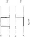
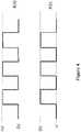
- the high driving voltage applied in Figure 2-1may be a single pulse as shown in Figure 3(a) or 3(b) or a pulsing waveform as shown in Figure 4(a) or 4(b).
- the pulsing waveformhas alternating 0V and a driving voltage.
- the magnitude of the driving voltage referred tomay be or may not be the same as that of the driving voltage for the single pulse method.
- the pulsing waveformmay lead to better color performance because it can prevent aggregation of the particles with each other, which usually causes reduction of hiding power of the layers of the particles.
- attraction forcein the context of the present application, encompasses electrostatic interactions, linearly dependent on the particle charge potentials, and the attraction force can be further enhanced by introducing other forces, such as Van der Waals forces, hydrophobic interactions or the like.
- the electric field generated by the low driving voltageis sufficient to separate the low negative white particles and low positive red particles to cause the red particles to move to the common electrode (21) side (i.e., the viewing side) and the white particles to move to the pixel electrode (22a) side.
- the white particlesare closest to the pixel electrode.
- the low positive driving voltages in Figure 2-2may be applied as a single pulse as shown in Figure 3 or a pulsing waveform as shown in Figure 4 .
- the magnitude of the driving voltage in the pulsing waveformmay be the same as, or different from, that of the single driving pulse. In the pulsing waveform, there may be 10-200 cycles of pulsing.
- the yellow, green, black and blue particlesstay in the middle of the pixel in a mixed state.
- the electric field generated by the low driving voltageis sufficient to separate the low negative white particles and the low positive red particles to cause the white particles to move to the common electrode side (i.e., the viewing side) and the red particles move to the pixel electrode side.
- the red particlesin this case, are closest to the pixel electrode.
- the low negative driving voltagemay be applied as a single pulse as shown in Figure 3 or a pulsing waveform as shown in Figure 4 .
- the magnitude of the driving voltage in the pulsing waveformmay be the same as, or different from, that of the single driving pulse. In the pulsing waveform, there may be 10-200 cycles of pulsing.
- magnitude of +3V in Figure 2-2is different from the magnitude of -5V in Figure 2-3 .
- the magnitude of the charge carried by the mid positive particlesmay be different from the magnitude of the charge carried by the mid negative particles
- the magnitude of the charge carried by the low positive particlesmay be different from the magnitude of the charge carried by the low negative particles.
- the driving voltage referred tois a low driving voltage.
- Figure 2-4shows how a blue color state (which is the color of the second highest positively charged particles) may be driven from the white state (which is the color of the lowest negatively charged particles).
- a medium positive driving voltage(e.g., +12V) is applied to a pixel 2(d) in the white state.
- the voltage appliedis not sufficient to separate the high positive black from the high negative yellow particles, but sufficient to cause the mid positive blue particles and the mid negative green particles to break away from the pack.
- the mid positive blue particles and the low positive red particlesmove to the viewing side while the red particles move slower than the blue particles because the red particles carry a lower charge potential.
- the blue particleswere closer to the common electrode side. As a result, a blue color is seen at the viewing side.
- the mid negative green particles and the low negative white particlesmove to the non-viewing side while the white particles move slower than the green particles because the white particles carry a lower charge potential.
- the green particleswere closer to the pixel electrode. As a result, a green color appears at the pixel electrode side.
- the electric field generated by the mid positive driving voltage of +12Vis sufficient to separate the low negative white from the high positive black particles.
- the low positive red particlesmay be separated from the high negative yellow particles when they move from the pixel electrode side to the common electrode side.
- the blue particleshave a higher charge potential and move faster than the red particles, and they were also closer to the common electrode side, they reach the common electrode side before the red particles. As a result, a high-quality blue color can be seen at the viewing side.
- This single pulse method with a medium positive driving voltagemay lead to the blue color state, with proper timing.
- the driving time for the single pulsemay be in the range of about 100 to about 2,000 msec. If the pulse is applied for too long, the red particles will catch up with the blue particles on the viewing side, which may cause some red tint appearing in the blue state.
- the driving as shown in Figure 2-4may be achieved by a pulsing waveform as shown in Figure 4 .
- the pulsing waveformhas alternating 0V and a driving voltage.
- the driving voltage referred tohas a magnitude which may or may not be the same as that of the driving voltage for the single pulse method. There may be 10-200 cycles of pulsing.
- the pulsing waveformmay lead to better color performance because it can prevent aggregation of the blue particles with each other, which usually causes reduction of hiding power of the layers of the particles.
- the blue statemay also be achieved according to Figure 2-5 .
- a mid positive driving voltagee.g., +8V
- +8Vis applied to a pixel 2(d) in the white state.
- the electric field generated by this driving voltage appliedis also not sufficient to separate the high positive black from the high negative yellow particles, but sufficient to cause the mid positive blue particles to break away from the pack and move towards the viewing side.
- the red particlesas explained above, also move towards the common electrode side, but slower than the blue particles.
- Figure 2-5introduces the possibility that the electric field generated by the driving voltage of +8V is not sufficient to separate the mid negative green particles and the low negative white particles from the high positive black particles.
- the non-viewing sidemay show a mixed color state of yellow, green white and black.
- This driving sequencemay also be accomplished by a single pulse method as shown in Figure 3 or a pulsing waveform of Figure 4 .
- Figure 2-6shows how a green color state (which is the color of the second highest negatively charged particles) may be driven from the red state (which is the color of the lowest positively charged particles).
- a medium negative driving voltage(e.g., -10V) is applied to a pixel 2(c) in the red state.
- the voltage appliedis not sufficient to separate the high positive black particles from the high negative yellow particles, but sufficient to cause the mid negative green particles and the mid positive blue particles to break away from the pack.
- the mid negative green particles and the low negative white particlesmove to the viewing side while the white particles move slower than the green particles because the white particles carry a lower charge potential.
- the green particleswere closer the common electrode side. As a result, a green color is seen at the viewing side.
- the mid positive blue particles and the low positive red particlesmove to the non-viewing side while the red particles move slower than the blue particles because the red particles carry a lower charge potential.
- the blue particleswere closer to the pixel electrode side. As a result, a blue color appears at the pixel electrode.
- the electric field generated by the mid negative driving voltage of -10Vis sufficient to separate the low positive red particles from the high negative yellow particles.
- the low negative white particlesmay be separated from the high positive black particles when they move from the pixel electrode side to the common electrode side.
- the green particleshave a higher charge potential and move faster than the white particles, and were closer to the common electrode in the starting pixel 2(a), they reach the common electrode side before the white particles. As a result, a high-quality green color can be seen at the viewing side.
- This single pulse method with a medium negative driving voltagemay lead to the green color state, with proper timing.
- the driving time for the single pulsemay be in the range of about 100 to about 2,000 msec. If the pulse is applied for too long, the white particles will catch up with the green particles on the viewing side, which may cause the green color to be in a lighter shade.
- the driving as shown in Figure 2-6may be achieved by a pulsing waveform as shown in Figure 4 .
- the pulsing waveformhas alternating 0V and a driving voltage.
- the driving voltage referred tohas a magnitude which may or may not be the same as that of the driving voltage for the single pulse method. There may be 10-200 cycles of pulsing.
- the pulsing waveformmay lead to better color performance because it can prevent aggregation of the green particles with each other, which usually causes reduction of hiding power of the layers of the particles.
- the green statemay also be achieved according to Figure 2-7 .
- a mid negative driving voltagee.g., -8V
- a pixel 2(c) in the red stateis applied to a mid negative driving voltage.
- the electric field generated by this driving voltage appliedis also not sufficient to separate the high positive black from the high negative yellow particles, but sufficient to cause the mid negative green particles to break away from the pack and move towards the viewing side.
- the white particlesas explained above, also move towards the common electrode side, but slower than the green particles.
- Figure 2-7introduces the possibility that the electric field generated by the driving voltage of -8V is not sufficient to separate the mid positive blue particles and the low positive red particles from the high negative yellow particles.
- the non-viewing sidemay show a mixed color state of yellow, blue, red and black.
- This driving sequencemay also be accomplished by a single pulse method as shown in Figure 3 or a pulsing waveform of Figure 4 .
- the driving voltage referred to in Figures 2-4 , 2-5 , 2-6 and 2-7is a medium driving voltage.
- the medium positive driving voltagemay be 40% to 100%, preferably 50% to 90%, of the high positive driving voltage, and the low positive driving voltage may be 5% to 50%, preferably 15% to 40%, of the high positive driving voltage.
- the medium negative driving voltagemay be 40% to 90%, preferably 50% to 80%, of the high negative driving voltage, and the low negative driving voltage may be 10% to 90%, preferably 30% to 70%, of high negative driving voltage.
- the "high" driving voltage (positive or negative) referred to aboveis usually the driving voltage required to drive a pixel from a color state of one type of the highest charged particles to a color state of another type of highest charged particles which are oppositely charged.
- the high driving voltagewould be the voltage applied for driving a pixel from the black state to the yellow state, or vice versa.
- Figures 5 and 6depict a set of driving schemes which are useful for driving a pixel from a black state (which is the color state of the highest positive particles) to a white state (which is the color state of the lowest negative particles, or for driving a pixel from a yellow state (which is the color state of the highest negative particles to a red state (which is the color state of the lowest positive particles).
- a high negative driving voltage(V2, e.g., -15V) is applied to a pixel for a period of t1 to drive the pixel towards the yellow state, which is followed by a positive driving voltage (+V1') for a period of t2 to drive the pixel towards the red state.
- V2e.g., -15V
- +V1'positive driving voltage
- t2is greater than t1.
- t1may be in the range of 20-400 msec and t2 may be ⁇ 200 msec.
- the waveform of Figure 5is repeated for at least 2 cycles (N ⁇ 2), preferably at least 4 cycles and more preferably at least 8 cycles.
- the red colorbecomes more intense after each driving cycle.
- a high positive driving voltage(V1, e.g., +15V) is applied to a pixel for a period of t3 to drive the pixel to the black state, which is followed by a negative driving voltage (-V2') for a period of t4 to drive the pixel towards the white state.
- V1positive positive driving voltage
- -V2'negative driving voltage
- the magnitude of -V2'is lower than that of V1.
- the magnitude of the -V2'is less than 50% of the magnitude of V1.
- t4is greater than t3.
- t3may be in the range of 20-400 msec and t4 may be ⁇ 200 msec.
- the waveform of Figure 6is repeated for at least 2 cycles (N ⁇ 2), preferably at least 4 cycles and more preferably at least 8 cycles.
- the white colorbecomes more intense after each driving cycle.
- the white and red color states achieved by these alternative driving schemesmay be used as a starting color of a pixel to be driven to other color states.
- the red color state achieved in Figure 5may be driven to the green state or the white color state achieved in Figure 6 may be driven to the blue state, as described in previous sections.
- each particle type/colorcan occupy 100% of the pixel area at a particular driving voltage, brightness of each individual color state is not compromised.
- This type of full color EPD displaywill provide not only the non-compromising white and black states, but also non-compromising color states of other colors, such as red, green and blue.
- each of the pixelscan display six color states. More color states may be displayed if a pixel consists of three sub-pixels and each of the sub-pixels, as described above, can display six color states. For example, one of the six color states may be displayed by the pixel if all three sub-pixels display that color. In addition, if the three sub-pixels display red, blue and black color states respectively, the pixel will be seen in a magenta color state. If the three sub-pixels display green, blue and black color states respectively, the pixel will be seen in a cyan color state. If the three sub-pixels display red, green and black color states respectively, the pixel will be seen in a yellow color state.
- More color statesmay be displayed through adjusting driving waveforms or image processing.
- the electrophoretic fluid as described aboveis filled in display cells.
- the display cellsmay be microcells as described in US Patent No. 6,930,818 .
- the display cellsmay also be other types of micro-containers, such as microcapsules, microchannels or equivalents, regardless of their shapes or sizes.
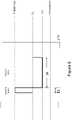
- Figure 7is a cross-section view of an array of display cells.
- the display cells (70) and the pixel electrodes (72a)do not have to be aligned.
- Each pixel (72)may display a color state depending on the driving voltage applied between the common electrode (71) and the corresponding pixel electrode (72a).
- a display cellmay be associated with more than one pixel electrode, which leads to the possibility of a display cell displaying more than one color state, as shown.
- the display device using the driving method of the present inventionmay also be used for decoration purposes, for example, in clothing and accessories (e.g., hats, shoes or wrist bands).
- the fluid used in the driving method of the present inventionmay further comprise substantially uncharged neutral buoyancy particles.
- substantially unchargedrefers to the particles which are either uncharged or carry a charge which is less than 5% of the average charge carried by the higher charged particles.
- the neutral buoyancy particlesare non-charged.
- neutral buoyancyrefers to particles which do not rise or fall with gravity. In other words, the particles would float in the fluid between the two electrode plates.
- the density of the neutral buoyancy particlesmay be the same as the density of the solvent or solvent mixture in which they are dispersed.
- the concentration of the substantially uncharged neutral buoyancy particles in the display fluidis preferably in the range of about 0.1 to about 10% by volume, more preferably in the range of about 0.1 to about 5% by volume.
- the substantially uncharged neutral buoyancy particlesmay be formed from a polymeric material.
- the polymeric materialmay be a copolymer or a homopolymer.
- polymeric material for the substantially uncharged neutral buoyancy particlesmay include, but are not limited to, polyacrylate, polymethacrylate, polystyrene, polyaniline, polypyrrole, polyphenol and polysiloxane.
- Specific examples of the polymeric materialmay include, but are not limited to, poly(pentabromophenyl methacrylate), poly(2-vinylnapthalene), poly(naphthyl methacrylate), poly(alpha-methystyrene), poly(N-benzyl methacrylamide) and poly(benzyl methacrylate).
- the substantially uncharged neutral buoyancy particlesare formed from a polymer which is not soluble in the solvent of the display fluid, and also has a high refractive index.
- the refractive index of the substantially uncharged neutral buoyancy particlesis different from that of the solvent or solvent mixture in which the particles are dispersed.
- typically the refractive index of the substantially uncharged neutral buoyancy particlesis higher than that of the solvent or solvent mixture. In some cases, the refractive index of the substantially uncharged neutral buoyancy particles may be above 1.45.
- the materials for the substantially uncharged neutral buoyancy particlesmay comprise an aromatic moiety.
- the substantially uncharged neutral buoyancy particlesmay be prepared from monomers through polymerization techniques, such as suspension polymerization, dispersion polymerization, seed polymerization, soap-free polymerization, emulsion polymerization or physical method, including inverse emulsification-evaporation process.
- the monomersare polymerized in the presence of a dispersant.
- the presence of the dispersantallows the polymer particles to be formed in a desired size range and the dispersant may also form a layer physically or chemically bonded to the surface of the polymer particles to prevent the particles from agglomeration.
- the dispersantpreferably has a long chain (of at least eight atoms), which may stabilize the polymer particles in a hydrocarbon solvent.
- Such dispersantsmay be an acrylate-terminated or vinyl-terminated macromolecule, which are suitable because the acrylate or vinyl group can co-polymerize with the monomer in the reaction medium.
- dispersantis acrylate terminated polysiloxane (Gelest, MCR-M17, MCR-M22),
- the backbone of the macromonomermay be a polyethylene chain and the integer "n" may be 30-200.
- the synthesis of this type of macromonomersmay be found in Seigou Kawaguchi et al, Designed Monomers and Polymers, 2000, 3, 263 .
- the dispersantsare then preferably also fluorinated.
- the substantially uncharged neutral buoyancy particlesmay also be formed from a core particle coated with a polymeric shell and the shell may be formed, for example, from any of the polymeric material identified above.
- the core particlemay be of an inorganic pigment such as TiO 2 , ZrO 2 , ZnO, Al 2 O 3 , CI pigment black 26 or 28 or the like (e.g., manganese ferrite black spinel or copper chromite black spinel), or an organic pigment such as phthalocyanine blue, phthalocyanine green, diarylide yellow, diarylide AAOT yellow, and quinacridone, azo, rhodamine, perylene pigment series from Sun Chemical, Hansa yellow G particles from Kanto Chemical, and Carbon Lampblack from Fisher, or the like.
- an inorganic pigmentsuch as TiO 2 , ZrO 2 , ZnO, Al 2 O 3 , CI pigment black 26 or 28 or the like (e.g., manganese ferrite black spinel or copper chromite black spinel), or an organic pigment such as phthalocyanine blue, phthalocyanine green, diarylide yellow, diarylide AAOT yellow, and quinacridone, azo
- core-shell substantially uncharged neutral buoyancy particlesthey may be formed by a microencapsulation method, such as coacervation, interfacial polycondensation, interfacial cross-linking, in-suit polymerization or matrix polymerization.
- a microencapsulation methodsuch as coacervation, interfacial polycondensation, interfacial cross-linking, in-suit polymerization or matrix polymerization.
- the size of the substantially uncharged neutral buoyancy particlesis preferably in the range of about 100 nanometers to about 5 microns.
- the substantially uncharged neutral buoyancy particles added to the fluidmay have a color substantially the same visually to the color of one of the six types of charged particles.
- the substantially uncharged neutral buoyancy particlesmay be white, black, red, yellow, green or blue.
- the substantially uncharged neutral buoyancy particlesmay have a color substantially different from the color of either one of the six types of charged particles.
- the presence of the substantially uncharged neutral buoyancy particles in the fluidincreases reflection of incident light, thus also improving the contrast ratio, especially if they are formed from a reflective material.
- the image stabilitymay also be improved by the addition of the substantially uncharged neutral buoyancy particles in the six particle fluid system.
- the substantially uncharged neutral buoyancy particlescan fill in the gaps resulted from the charged particles being over packed on the surface of an electrode under an electrical field, thus preventing the charged particles from settling due to the gravitational force.
- substantially uncharged neutral buoyancy particlesare white, they may enhance the reflectivity of the display. If they are black, they may enhance the blackness of the display.
- the substantially uncharged neutral buoyancy particlesdo not affect the driving behavior of the six types of charged particles in the fluid.
Landscapes
- Physics & Mathematics (AREA)
- Engineering & Computer Science (AREA)
- General Physics & Mathematics (AREA)
- Nonlinear Science (AREA)
- Computer Hardware Design (AREA)
- Theoretical Computer Science (AREA)
- Optics & Photonics (AREA)
- Chemical & Material Sciences (AREA)
- Life Sciences & Earth Sciences (AREA)
- Health & Medical Sciences (AREA)
- Chemical Kinetics & Catalysis (AREA)
- Electrochemistry (AREA)
- Molecular Biology (AREA)
- Mathematical Physics (AREA)
- Crystallography & Structural Chemistry (AREA)
- Electrochromic Elements, Electrophoresis, Or Variable Reflection Or Absorption Elements (AREA)
- Control Of Indicators Other Than Cathode Ray Tubes (AREA)
- Devices For Indicating Variable Information By Combining Individual Elements (AREA)
Description
- The present invention relates to a method of driving a color electrophoretic display device in which each pixel can display multiple high-quality color states.
- In order to achieve a color display, color filters are often used. The most common approach is to add color filters on top of black/white sub-pixels of a pixellated display to display the red, green and blue colors. When a red color is desired, the green and blue sub-pixels are turned to the black state so that the only color displayed is red. When a blue color is desired, the green and red sub-pixels are turned to the black state so that the only color displayed is blue. When a green color is desired, the red and blue sub-pixels are turned to the black state so that the only color displayed is green. When the black state is desired, all three-sub-pixels are turned to the black state. When the white state is desired, the three sub-pixels are turned to red, green and blue, respectively, and as a result, a white state is seen by the viewer.
- The biggest disadvantage of using such a technique for a reflective display is that since each of the sub-pixels has a reflectance of about one third of the desired white state, the white state is fairly dim. To compensate this, a fourth sub-pixel may be added which can display only the black and white states, so that the white level is doubled at the expense of the red, green or blue color level (where each sub-pixel is only one fourth of the area of the pixel). Brighter colors can be achieved by adding light from the white pixel, but this is achieved at the expense of color gamut to cause the colors to be very light and unsaturated. A similar result can be achieved by reducing the color saturation of the three sub-pixels. Even with this approach, the white level is normally substantially less than half of that of a black and white display, rendering it an unacceptable choice for display devices, such as e-readers or displays that need well readable black-white brightness and contrast.
EP 1 857 864 A1claim 1 is based, discloses the display of colors in an electrophoretic multi-color system being applied to a display medium containing any number of differently colored particle sets, for example including two, three, four or even more particle sets.US 2011/0007381 A1 andWO 2013/167814 A1 are further documents of the prior art.- The present invention is defined in
independent claim 1. Preferred embodiments are claimed in the dependent claims. Figure 1 depicts a display layer which can display different color states.Figures 2-1 to 2-7 illustrate how different color states can be displayed.Figure 3 demonstrates single driving pulses.Figure 4 demonstrates pulsing waveforms.Figures 5 and6 illustrate alternative driving schemes.Figure 7 demonstrates display cells unaligned with pixel electrodes.- The electrophoretic fluid used in the method of the present invention comprises at least six types of particles dispersed in a dielectric solvent or solvent mixture.
- The particles may be referred to as a first type of particles, a second type of particles, a third type of particles, a fourth type of particles, a fifth type of particles and a sixth type of particles, as shown in
Figure 1 . The six types of particles are of different colors. - It is understood that the scope of the invention broadly encompasses particles of any colors as long as the multiple types of particles are visually distinguishable. As an example, the six types of particles may be any combinations of white particles (W), black particles (K), red particles (R), green particles (G), blue particles (B), cyan particles (C), magenta particles (M) and yellow particles (Y).
- In addition to the colors, the six different types of particles may have other distinct optical characteristics, such as optical transmission, reflectance, luminescence or, in the case of displays intended for machine reading, pseudo-color in the sense of a change in reflectance of electromagnetic wavelengths outside the visible range.
- In addition, the six types of particles have different levels of charge potential. For example, the six types of particles may be high-positive particles, mid-positive particles, low-positive particles, high-negative particles, mid-negative and low-negative particles.
- It is noted that the term "charge potential", in the context of the present application, may be used interchangeably with "zeta potential".
- The charge polarities and levels of charge potential of the particles may be tuned, according to the method described in
U.S. Patent Application Publication No. 2014-0011913 . - The magnitudes of the "high-positive" particles and the "high-negative" particles may be the same or different. Likewise, the magnitudes of the "mid-positive" particles and the "mid-negative" particles may be the same or different, and the magnitudes of the "low-positive" particles and the "low-negative" particles may be the same or different.
- The charge potentials of the particles may be measured in terms of zeta potential. In one embodiment, the zeta potential is determined by Colloidal Dynamics AcoustoSizer IIM with a CSPU-100 signal processing unit, ESA EN# Attn flow through cell (K:127). The instrument constants, such as density of the solvent used in the sample, dielectric constant of the solvent, speed of sound in the solvent, viscosity of the solvent, all of which at the testing temperature (25ºC) are entered before testing. Pigment samples are dispersed in the solvent (which is usually a hydrocarbon fluid having less than 12 carbon atoms), and diluted to be 5-10% by weight. The sample also contains a charge control agent (SOLSPERSE® 17000, available from Lubrizol Corporation, a Berkshire Hathaway company), with a weight ratio of 1:10 of the charge control agent to the particles.
- The mass of the diluted sample is determined and the sample is then loaded into the flow-through cell for determination of the zeta potential.
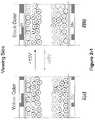
- As shown, the display fluid is sandwiched between two electrode layers. One of the electrode layers is a common electrode (11) which is a transparent electrode layer (e.g., ITO), spreading over the entire top of the display device. The other electrode layer (12) is a layer of pixel electrodes (12a).
- The space between two dotted vertical lines denotes a pixel. Therefore, each pixel has a corresponding pixel electrode (12a).
- The pixel electrodes are described in
US Patent No. 7,046,228 . It is noted that while active matrix driving with a thin film transistor (TFT) backplane is mentioned for the layer of pixel electrodes, the present invention encompasses other types of electrode addressing as long as the electrodes serve the desired functions. - As also shown in
Figure 1 , a display device which can be driven by the driving method of the present invention has two surfaces, a first surface (13) on the viewing side and a second surface (14) on the opposite side of the first surface (13). The second surface therefore is on the non-viewing side. The term "viewing side" refers to the side at which images are viewed. - The solvent in which the particles are dispersed is clear and colorless. It preferably has a dielectric constant in the range of about 2 to about 30, more preferably about 2 to about 15 for high particle mobility. Examples of suitable dielectric solvent include hydrocarbons such as isoparaffin, decahydronaphthalene (DECALIN), 5-ethylidene-2-norbornene, fatty oils, paraffin oil, silicon fluids, aromatic hydrocarbons such as toluene, xylene, phenylxylylethane, dodecylbenzene or alkylnaphthalene, halogenated solvents such as perfluorodecalin, perfluorotoluene, perfluoroxylene, dichlorobenzotrifluoride, 3,4,5 -trichlorobenzotrifluoride, chloropentafluoro-benzene, dichlorononane or pentachlorobenzene, and perfluorinated solvents such as FC-43, FC-70 or FC-5060 from 3M Company, St. Paul MN, low molecular weight halogen containing polymers such as poly(perfluoropropylene oxide) from TCI America, Portland, Oregon, poly(chlorotrifluoro-ethylene) such as Halocarbon Oils from Halocarbon Product Corp., River Edge, NJ, perfluoropolyalkylether such as Galden from Ausimont or Krytox Oils and Greases K-Fluid Series from DuPont, Delaware, polydimethylsiloxane based silicone oil from Dow-corning (DC -200).
- The particles are preferably opaque. They may be primary particles without a polymer shell. Alternatively, each particle may comprise an insoluble core with a polymer shell. The core could be either an organic or inorganic pigment, and it may be a single core particle or an aggregate of multiple core particles. The particles may also be hollow particles.
- In the case of white particles (W), the primary particles or core particles may be TiO2, ZrO2, ZnO, Al2O3, Sb2O3, BaSO4, PbSO4 or the like.
- For the black particles (K), the primary particles or core particles may be CI pigment black 26 or 28 or the like (e.g., manganese ferrite black spinel or copper chromite black spinel) or carbon black.
- For the other colored particles (which are non-white and non-black), the primary particles or core particles may include, but are not limited to, CI pigment PR 254, PR122, PR149, PG36, PG58, PG7, PB28, PB15:3, PY83, PY138, PY150, PY155 or PY20. Those are commonly used organic pigments described in color index handbooks, "New Pigment Application Technology" (CMC Publishing Co, Ltd, 1986) and "Printing Ink Technology" (CMC Publishing Co, Ltd, 1984). Specific examples include Clariant Hostaperm Red D3G 70-EDS, Hostaperm Pink E-EDS, PV fast red D3G, Hostaperm
red D3G 70, Hostaperm Blue B2G-EDS, Hostaperm Yellow H4G-EDS, F2G-EDS, Novoperm Yellow HR-70-EDS, Hostaperm Green GNX, BASF Irgazine red L 3630, Cinquasia Red L 4100 HD, and Irgazin Red L 3660 HD; Sun Chemical phthalocyanine blue, phthalocyanine green, diarylide yellow or diarylide AAOT yellow. - For the other colored particles (which are non-white and non-black), the primary particles or core particles may also be inorganic pigments, such as red, green, blue and yellow pigments. Examples may include, but are not limited to, CI pigment blue 28, CI pigment green 50 and CI pigment yellow 227.
- The percentages of different types of particles in the fluid may vary. For example, one type of particles may take up 0.1% to 10%, preferably 0.5% to 5%, by volume of the electrophoretic fluid; another type of particles may take up 1% to 50%, preferably 5% to 20%, by volume of the fluid; and each of the remaining types of particles may take up 2% to 20%, preferably 4% to 10%, by volume of the fluid.
- It is also noted that the six types of particles may have different particle sizes. For example, the smaller particles may have a size which ranges from about 50 nm to about 800nm. The larger particles may have a size which is about 2 to about 50 times, more preferably about 2 to about 10 times, the sizes of the smaller particles.
- An electrophoretic fluid of the present invention comprises six types of particles and the colors are displayed because of different levels of attraction forces among the particles.
- Among the six types of particles, three types carry a charge polarity opposite from the charge polarity of the other three types.
- The following is an example illustrating the present invention. In this example as shown in
Figure 2 , the black particles (K) (i.e., the first type) carry a positive charge and the yellow particles (Y) (i.e., the second type) carry a negative charge. - The blue (B) (i.e., the third type) and red (R) (i.e., the fifth type) particles are positively charged; but their magnitudes are progressively less than that of the black particles, which means that the black particles are high-positive particles, the blue particles are mid-positive particles and the red particles are low-positive particles.
- The green (G) (i.e., the fourth type) and white (W) particles (i.e., the sixth type) are negatively charged; but their magnitude are progressively less than that of the yellow particles, which means that the yellow particles are high-negative particles, the green particles are mid-negative particles and the white particles are low-negative particles.
- In
Figure 2-1 , when a high negative driving voltage (e.g., -15V) is applied to the pixel 2(a) for a time period of sufficient length, an electric field is generated to cause the high negative yellow particles to be pushed to the common electrode (21) side and the high positive black particles pulled to the pixel electrode (22a) side. - The low positive red and mid positive blue particles also move towards the pixel electrode, but move slower than the high positive black particles and as a result, the blue particles are above the black particles but below the red particles because the blue particles carry a higher charge potential than the red particles. The black particles are closest to the pixel electrode side.
- The mid negative green particles and the low negative white particles also move towards the common electrode, but move slower than the high negative yellow particles, and therefore the green particles are above the white particles but below the yellow particles because the green particles carry a higher charge potential than the white particles. The yellow particles are closest to the common electrode side, and the green and white particles are hidden underneath the yellow particles. As a result, a yellow color is seen at the viewing side (see pixel 2(a)).
- In
Figure 2-1 , when a high positive driving voltage (e.g., +15V) is applied to the pixel 2(b) for a time period of sufficient length, an electric field of a positive polarity is generated which causes the particle distribution to be opposite of that shown in Figure 2(a) and as a result, a black color is seen at the viewing side. - It is also noted that the high driving voltage applied in
Figure 2-1 may be a single pulse as shown in Figure 3(a) or 3(b) or a pulsing waveform as shown in Figure 4(a) or 4(b). - The pulsing waveform has alternating 0V and a driving voltage. The magnitude of the driving voltage referred to may be or may not be the same as that of the driving voltage for the single pulse method. There may be 10-200 cycles of pulsing. The pulsing waveform may lead to better color performance because it can prevent aggregation of the particles with each other, which usually causes reduction of hiding power of the layers of the particles.
- In
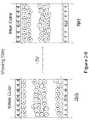
Figure 2-2 , when a low positive driving voltage (e.g., +3V) is applied to the pixel 2(a) (that is, driven from the yellow state) for a time period of sufficient length, an electric field is generated to cause the high negative yellow particles and mid negative green particles to move towards the pixel electrode (22a) while the high positive black and mid positive blue particles move towards the common electrode (21). However, when they meet in the middle of the pixel, they significantly slow down and remain there because the electric field generated by the low driving voltage is not strong enough to overcome the attraction forces between them. As shown, the yellow, green, black and blue particles stay in the middle of the pixel in a mixed state. - The term "attraction force" in the context of the present application, encompasses electrostatic interactions, linearly dependent on the particle charge potentials, and the attraction force can be further enhanced by introducing other forces, such as Van der Waals forces, hydrophobic interactions or the like.
- On the other hand, there are also attraction forces between low positive red particles with the high negative yellow particles and mid negative green particles, and the low negative white particles with high positive black and the mid positive blue particles. However, these attraction forces are not as strong as the attraction forces between the black, blue, yellow and green particles, and therefore they can be overcome by the electric field generated by the low driving voltage. In other words, the low charged particles and the high or mid charged particles of opposite polarity can be separated.
- In addition, the electric field generated by the low driving voltage is sufficient to separate the low negative white particles and low positive red particles to cause the red particles to move to the common electrode (21) side (i.e., the viewing side) and the white particles to move to the pixel electrode (22a) side. As a result, a red color is seen. In this case, the white particles are closest to the pixel electrode.
- The low positive driving voltages in
Figure 2-2 may be applied as a single pulse as shown inFigure 3 or a pulsing waveform as shown inFigure 4 . The magnitude of the driving voltage in the pulsing waveform may be the same as, or different from, that of the single driving pulse. In the pulsing waveform, there may be 10-200 cycles of pulsing. - In
Figure 2-3 , when a low negative driving voltage (e.g., -5V) is applied to the pixel 2(b) (that is, driven from the black state) for a time period of sufficient length, an electric field is generated which causes the high positive black and the mid positive blue particles to move towards the pixel electrode (22a) while the high negative yellow particles and the mid negative green particles move towards the common electrode (21). However, when they meet in the middle of the pixel, they significantly slow down and remain there because the electric field generated by the low driving voltage is not strong enough to overcome the attraction between them. - As shown, the yellow, green, black and blue particles stay in the middle of the pixel in a mixed state.
- At the same time, there are also attraction forces between the low positive red particles with high negative yellow particles and the mid negative green particles, and between low negative white particles with high positive black and the mid positive blue particles. However, these attraction forces are not as strong as the attraction forces between the black, blue, yellow and green particles, and therefore they can be overcome by the electric field generated by the low driving voltage. In other words, low charged particles and the high or mid charged particles of opposite polarity can be separated.
- In addition, the electric field generated by the low driving voltage is sufficient to separate the low negative white particles and the low positive red particles to cause the white particles to move to the common electrode side (i.e., the viewing side) and the red particles move to the pixel electrode side. As a result, a white color is seen. The red particles, in this case, are closest to the pixel electrode.
- The low negative driving voltage may be applied as a single pulse as shown in
Figure 3 or a pulsing waveform as shown inFigure 4 . The magnitude of the driving voltage in the pulsing waveform may be the same as, or different from, that of the single driving pulse. In the pulsing waveform, there may be 10-200 cycles of pulsing. - It is noted that magnitude of +3V in
Figure 2-2 is different from the magnitude of -5V inFigure 2-3 . This is due to the fact that, as stated above, the magnitude of the charge carried by the mid positive particles may be different from the magnitude of the charge carried by the mid negative particles, and the magnitude of the charge carried by the low positive particles may be different from the magnitude of the charge carried by the low negative particles. - In this driving method, the driving voltage referred to is a low driving voltage.
- There are alternative driving schemes which may be used to drive a pixel from black to white or yellow to red, which schemes are described in a section below.
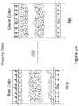
Figure 2-4 shows how a blue color state (which is the color of the second highest positively charged particles) may be driven from the white state (which is the color of the lowest negatively charged particles).- In one scenario, a medium positive driving voltage (e.g., +12V) is applied to a pixel 2(d) in the white state. The voltage applied is not sufficient to separate the high positive black from the high negative yellow particles, but sufficient to cause the mid positive blue particles and the mid negative green particles to break away from the pack.
- In this scenario, the mid positive blue particles and the low positive red particles move to the viewing side while the red particles move slower than the blue particles because the red particles carry a lower charge potential. In addition, the blue particles were closer to the common electrode side. As a result, a blue color is seen at the viewing side.
- The mid negative green particles and the low negative white particles move to the non-viewing side while the white particles move slower than the green particles because the white particles carry a lower charge potential. In addition, the green particles were closer to the pixel electrode. As a result, a green color appears at the pixel electrode side.
- It is noted that in this process, when the white particles pass the black and yellow particles in the middle area to move towards the pixel electrode, the electric field generated by the mid positive driving voltage of +12V is sufficient to separate the low negative white from the high positive black particles. Similarly, the low positive red particles may be separated from the high negative yellow particles when they move from the pixel electrode side to the common electrode side.
- However, as stated, because the blue particles have a higher charge potential and move faster than the red particles, and they were also closer to the common electrode side, they reach the common electrode side before the red particles. As a result, a high-quality blue color can be seen at the viewing side.
- This single pulse method with a medium positive driving voltage may lead to the blue color state, with proper timing. The driving time for the single pulse may be in the range of about 100 to about 2,000 msec. If the pulse is applied for too long, the red particles will catch up with the blue particles on the viewing side, which may cause some red tint appearing in the blue state.
- Alternatively, the driving as shown in
Figure 2-4 may be achieved by a pulsing waveform as shown inFigure 4 . The pulsing waveform has alternating 0V and a driving voltage. The driving voltage referred to has a magnitude which may or may not be the same as that of the driving voltage for the single pulse method. There may be 10-200 cycles of pulsing. The pulsing waveform may lead to better color performance because it can prevent aggregation of the blue particles with each other, which usually causes reduction of hiding power of the layers of the particles. - Alternatively, the blue state may also be achieved according to
Figure 2-5 . A mid positive driving voltage (e.g., +8V) is applied to a pixel 2(d) in the white state. - The electric field generated by this driving voltage applied is also not sufficient to separate the high positive black from the high negative yellow particles, but sufficient to cause the mid positive blue particles to break away from the pack and move towards the viewing side.
- The red particles, as explained above, also move towards the common electrode side, but slower than the blue particles.
Figure 2-5 , however, introduces the possibility that the electric field generated by the driving voltage of +8V is not sufficient to separate the mid negative green particles and the low negative white particles from the high positive black particles. As a result, when the blue color state is seen at the viewing side, the non-viewing side may show a mixed color state of yellow, green white and black.- This scenario is possible because the magnitude of the mid positive blue particles is not the same as the magnitude of the mid negative green particles and the magnitude of the low positive red particles is not the same as the magnitude of the low negative white particles.
- This driving sequence may also be accomplished by a single pulse method as shown in
Figure 3 or a pulsing waveform ofFigure 4 . - It should also be noted that in
Figure 2-4 , a green color is at the pixel electrode side and inFigure 2-5 , a mixed color is at the pixel electrode side. - There is another possibility which is not shown in these figures, that is, when a positive voltage is applied to the pixel 2(d), because of the different charge potentials carried by the green and white particles, only the green particles are trapped by the high positive black particles and the white particles may break free from the pack and move to the pixel electrode side. In this scenario, a white color is at the pixel electrode side.
Figure 2-6 shows how a green color state (which is the color of the second highest negatively charged particles) may be driven from the red state (which is the color of the lowest positively charged particles).- In one scenario, a medium negative driving voltage (e.g., -10V) is applied to a pixel 2(c) in the red state. The voltage applied is not sufficient to separate the high positive black particles from the high negative yellow particles, but sufficient to cause the mid negative green particles and the mid positive blue particles to break away from the pack.
- In this scenario, the mid negative green particles and the low negative white particles move to the viewing side while the white particles move slower than the green particles because the white particles carry a lower charge potential. In addition, the green particles were closer the common electrode side. As a result, a green color is seen at the viewing side.
- The mid positive blue particles and the low positive red particles move to the non-viewing side while the red particles move slower than the blue particles because the red particles carry a lower charge potential. In addition, the blue particles were closer to the pixel electrode side. As a result, a blue color appears at the pixel electrode.
- It is noted that in this process, when the red particles pass the black and yellow particles in the middle area to move towards the pixel electrode, the electric field generated by the mid negative driving voltage of -10V is sufficient to separate the low positive red particles from the high negative yellow particles. Similarly, the low negative white particles may be separated from the high positive black particles when they move from the pixel electrode side to the common electrode side.
- However, as stated, because the green particles have a higher charge potential and move faster than the white particles, and were closer to the common electrode in the starting pixel 2(a), they reach the common electrode side before the white particles. As a result, a high-quality green color can be seen at the viewing side.
- This single pulse method with a medium negative driving voltage may lead to the green color state, with proper timing. The driving time for the single pulse may be in the range of about 100 to about 2,000 msec. If the pulse is applied for too long, the white particles will catch up with the green particles on the viewing side, which may cause the green color to be in a lighter shade.
- Alternatively, the driving as shown in
Figure 2-6 may be achieved by a pulsing waveform as shown inFigure 4 . The pulsing waveform has alternating 0V and a driving voltage. The driving voltage referred to has a magnitude which may or may not be the same as that of the driving voltage for the single pulse method. There may be 10-200 cycles of pulsing. The pulsing waveform may lead to better color performance because it can prevent aggregation of the green particles with each other, which usually causes reduction of hiding power of the layers of the particles. - Alternatively, the green state may also be achieved according to
Figure 2-7 . A mid negative driving voltage (e.g., -8V) is applied to a pixel 2(c) in the red state. - The electric field generated by this driving voltage applied is also not sufficient to separate the high positive black from the high negative yellow particles, but sufficient to cause the mid negative green particles to break away from the pack and move towards the viewing side.
- The white particles, as explained above, also move towards the common electrode side, but slower than the green particles.
Figure 2-7 , however, introduces the possibility that the electric field generated by the driving voltage of -8V is not sufficient to separate the mid positive blue particles and the low positive red particles from the high negative yellow particles. As a result, when the green color state is seen at the viewing side, the non-viewing side may show a mixed color state of yellow, blue, red and black.- This scenario is possible because the magnitude of the mid negative green particles is not the same as the magnitude of the mid positive blue particles, and the magnitude of the low negative white particles is not the same as the magnitude of the low positive red particles.
- This driving sequence may also be accomplished by a single pulse method as shown in
Figure 3 or a pulsing waveform ofFigure 4 . - It should also be noted that in
Figure 2-6 , a blue color is at the pixel electrodeside and inFigure 2-7 , a mixed color is at the pixel electrode side. - There is another possibility which is not shown in these figures, that is, when a positive voltage is applied to the pixel 2(c), because of the different charge potentials carried by the blue and red particles, only the blue particles are trapped by the high negative yellow particles and the red particles may break free from the pack and move to the pixel electrode side. In this scenario, a red color appears at the pixel electrode side.
- The driving voltage referred to in
Figures 2-4 ,2-5 ,2-6 and2-7 is a medium driving voltage. - As shown in this example, there are three levels of positive driving voltage, high positive, medium positive and low positive, and three levels of negative driving voltage, high negative, medium negative and low negative. The medium positive driving voltage may be 40% to 100%, preferably 50% to 90%, of the high positive driving voltage, and the low positive driving voltage may be 5% to 50%, preferably 15% to 40%, of the high positive driving voltage. The medium negative driving voltage may be 40% to 90%, preferably 50% to 80%, of the high negative driving voltage, and the low negative driving voltage may be 10% to 90%, preferably 30% to 70%, of high negative driving voltage.
- The "high" driving voltage (positive or negative) referred to above is usually the driving voltage required to drive a pixel from a color state of one type of the highest charged particles to a color state of another type of highest charged particles which are oppositely charged. In the example above, the high driving voltage would be the voltage applied for driving a pixel from the black state to the yellow state, or vice versa.
Figures 5 and6 depict a set of driving schemes which are useful for driving a pixel from a black state (which is the color state of the highest positive particles) to a white state (which is the color state of the lowest negative particles, or for driving a pixel from a yellow state (which is the color state of the highest negative particles to a red state (which is the color state of the lowest positive particles).- As shown in
Figure 5 , in an initial step, a high negative driving voltage (V2, e.g., -15V) is applied to a pixel for a period of t1 to drive the pixel towards the yellow state, which is followed by a positive driving voltage (+V1') for a period of t2 to drive the pixel towards the red state. The magnitude of +V1' is lower than that of V2. In one embodiment, the magnitude of the +V1' is less than 50% of the magnitude of V2. In one embodiment, t2 is greater than t1. In one embodiment, t1 may be in the range of 20-400 msec and t2 may be ≤ 200 msec. - The waveform of
Figure 5 is repeated for at least 2 cycles (N≥ 2), preferably at least 4 cycles and more preferably at least 8 cycles. The red color becomes more intense after each driving cycle. - As shown in
Figure 6 , in an initial step, a high positive driving voltage (V1, e.g., +15V) is applied to a pixel for a period of t3 to drive the pixel to the black state, which is followed by a negative driving voltage (-V2') for a period of t4 to drive the pixel towards the white state. The magnitude of -V2' is lower than that of V1. In one embodiment, the magnitude of the -V2' is less than 50% of the magnitude of V1. In one embodiment, t4 is greater than t3. In one embodiment, t3 may be in the range of 20-400 msec and t4 may be ≥ 200 msec. - The waveform of
Figure 6 is repeated for at least 2 cycles (N≥ 2), preferably at least 4 cycles and more preferably at least 8 cycles. The white color becomes more intense after each driving cycle. - The white and red color states achieved by these alternative driving schemes may be used as a starting color of a pixel to be driven to other color states. For example, the red color state achieved in
Figure 5 may be driven to the green state or the white color state achieved inFigure 6 may be driven to the blue state, as described in previous sections. - In the present invention, since the six color states are controlled by varying voltage levels and each particle type/color can occupy 100% of the pixel area at a particular driving voltage, brightness of each individual color state is not compromised. This type of full color EPD display will provide not only the non-compromising white and black states, but also non-compromising color states of other colors, such as red, green and blue.
- As described, each of the pixels can display six color states. More color states may be displayed if a pixel consists of three sub-pixels and each of the sub-pixels, as described above, can display six color states. For example, one of the six color states may be displayed by the pixel if all three sub-pixels display that color. In addition, if the three sub-pixels display red, blue and black color states respectively, the pixel will be seen in a magenta color state. If the three sub-pixels display green, blue and black color states respectively, the pixel will be seen in a cyan color state. If the three sub-pixels display red, green and black color states respectively, the pixel will be seen in a yellow color state.
- More color states may be displayed through adjusting driving waveforms or image processing.
- The electrophoretic fluid as described above is filled in display cells. The display cells may be microcells as described in
US Patent No. 6,930,818 . The display cells may also be other types of micro-containers, such as microcapsules, microchannels or equivalents, regardless of their shapes or sizes. Figure 7 is a cross-section view of an array of display cells. As shown, the display cells (70) and the pixel electrodes (72a) do not have to be aligned. Each pixel (72) may display a color state depending on the driving voltage applied between the common electrode (71) and the corresponding pixel electrode (72a). However, because the display cells and the pixel electrodes are not aligned, a display cell may be associated with more than one pixel electrode, which leads to the possibility of a display cell displaying more than one color state, as shown.- The display device using the driving method of the present invention, in addition to the common display applications, may also be used for decoration purposes, for example, in clothing and accessories (e.g., hats, shoes or wrist bands).
- The fluid used in the driving method of the present invention may further comprise substantially uncharged neutral buoyancy particles.
- The term "substantially uncharged" refers to the particles which are either uncharged or carry a charge which is less than 5% of the average charge carried by the higher charged particles. In one embodiment, the neutral buoyancy particles are non-charged.
- The term "neutral buoyancy" refers to particles which do not rise or fall with gravity. In other words, the particles would float in the fluid between the two electrode plates. In one embodiment, the density of the neutral buoyancy particles may be the same as the density of the solvent or solvent mixture in which they are dispersed.
- The concentration of the substantially uncharged neutral buoyancy particles in the display fluid is preferably in the range of about 0.1 to about 10% by volume, more preferably in the range of about 0.1 to about 5% by volume.
- The term "about" refers to a range which is ±10% of the indicated value.
- The substantially uncharged neutral buoyancy particles may be formed from a polymeric material. The polymeric material may be a copolymer or a homopolymer.
- Examples of the polymeric material for the substantially uncharged neutral buoyancy particles may include, but are not limited to, polyacrylate, polymethacrylate, polystyrene, polyaniline, polypyrrole, polyphenol and polysiloxane. Specific examples of the polymeric material may include, but are not limited to, poly(pentabromophenyl methacrylate), poly(2-vinylnapthalene), poly(naphthyl methacrylate), poly(alpha-methystyrene), poly(N-benzyl methacrylamide) and poly(benzyl methacrylate).
- More preferably, the substantially uncharged neutral buoyancy particles are formed from a polymer which is not soluble in the solvent of the display fluid, and also has a high refractive index. In one embodiment, the refractive index of the substantially uncharged neutral buoyancy particles is different from that of the solvent or solvent mixture in which the particles are dispersed. However, typically the refractive index of the substantially uncharged neutral buoyancy particles is higher than that of the solvent or solvent mixture. In some cases, the refractive index of the substantially uncharged neutral buoyancy particles may be above 1.45.
- In one embodiment, the materials for the substantially uncharged neutral buoyancy particles may comprise an aromatic moiety.
- The substantially uncharged neutral buoyancy particles may be prepared from monomers through polymerization techniques, such as suspension polymerization, dispersion polymerization, seed polymerization, soap-free polymerization, emulsion polymerization or physical method, including inverse emulsification-evaporation process. The monomers are polymerized in the presence of a dispersant. The presence of the dispersant allows the polymer particles to be formed in a desired size range and the dispersant may also form a layer physically or chemically bonded to the surface of the polymer particles to prevent the particles from agglomeration.
- The dispersant preferably has a long chain (of at least eight atoms), which may stabilize the polymer particles in a hydrocarbon solvent. Such dispersants may be an acrylate-terminated or vinyl-terminated macromolecule, which are suitable because the acrylate or vinyl group can co-polymerize with the monomer in the reaction medium.
- One specific example of the dispersant is acrylate terminated polysiloxane (Gelest, MCR-M17, MCR-M22),
- Another type of suitable dispersants is polyethylene macromonomers, as shown below:
CH3-[-CH2-]n-CH2O-C(=O)-C(CH3) = CH2 - The backbone of the macromonomer may be a polyethylene chain and the integer "n" may be 30-200. The synthesis of this type of macromonomers may be found in Seigou Kawaguchi et al, Designed Monomers and Polymers, 2000, 3, 263.
- If the fluid system is fluorinated, the dispersants are then preferably also fluorinated.
- Alternatively, the substantially uncharged neutral buoyancy particles may also be formed from a core particle coated with a polymeric shell and the shell may be formed, for example, from any of the polymeric material identified above.
- The core particle may be of an inorganic pigment such as TiO2, ZrO2, ZnO, Al2O3, CI pigment black 26 or 28 or the like (e.g., manganese ferrite black spinel or copper chromite black spinel), or an organic pigment such as phthalocyanine blue, phthalocyanine green, diarylide yellow, diarylide AAOT yellow, and quinacridone, azo, rhodamine, perylene pigment series from Sun Chemical, Hansa yellow G particles from Kanto Chemical, and Carbon Lampblack from Fisher, or the like.
- In the case of core-shell substantially uncharged neutral buoyancy particles, they may be formed by a microencapsulation method, such as coacervation, interfacial polycondensation, interfacial cross-linking, in-suit polymerization or matrix polymerization.
- The size of the substantially uncharged neutral buoyancy particles is preferably in the range of about 100 nanometers to about 5 microns.
- In one embodiment of this aspect of the present invention, the substantially uncharged neutral buoyancy particles added to the fluid may have a color substantially the same visually to the color of one of the six types of charged particles. For example, in a display fluid, there may be charged white, black, red, yellow, green and blue particles and substantially uncharged neutral buoyancy particles, and in this case, the substantially uncharged neutral buoyancy particles may be white, black, red, yellow, green or blue.
- In another embodiment, the substantially uncharged neutral buoyancy particles may have a color substantially different from the color of either one of the six types of charged particles.
- The presence of the substantially uncharged neutral buoyancy particles in the fluid increases reflection of incident light, thus also improving the contrast ratio, especially if they are formed from a reflective material.
- The image stability may also be improved by the addition of the substantially uncharged neutral buoyancy particles in the six particle fluid system. The substantially uncharged neutral buoyancy particles can fill in the gaps resulted from the charged particles being over packed on the surface of an electrode under an electrical field, thus preventing the charged particles from settling due to the gravitational force.
- In addition, if the substantially uncharged neutral buoyancy particles are white, they may enhance the reflectivity of the display. If they are black, they may enhance the blackness of the display.
- In any case, the substantially uncharged neutral buoyancy particles do not affect the driving behavior of the six types of charged particles in the fluid.
Claims (13)
- A method of driving an electrophoretic display comprising an electrophoretic medium, the electrophoretic medium having a first, viewing surface (13), and a second surface (14) on the opposed side from the first surface (13), the electrophoretic medium comprising a fluid and first (K), second (Y), third (B), fourth (G), fifth (R) and sixth (W) types of particles, all of which are dispersed in the fluid, wherein:(a) the six types of particles (K, Y, B, G, R, W) have optical characteristics differing from one another, the optical characteristics comprise colors or other optical characteristics such as transmissions, reflectances, luminescences, or changes in reflectances of electromagnetic wavelength outside the visible range;(b) the first (K), third (B) and fifth (R) types of particles carry charges of one polarity, the first type (K) of particles having a higher magnitude of zeta potential than the third type (B) of particles which themselves have a higher magnitude of zeta potential than the fifth type (R) of particles; and(c) the second (Y), fourth (G) and sixth (W) types of particles carry charges of the opposite polarity as the polarity of the charges carried by the first (K), third (B) and fifth (R) types of particles, the second type (Y) of particles having a higher magnitude of zeta potential than the fourth type (G) of particles which themselves have a higher magnitude of zeta potential than the sixth type (W) of particles; the electrophoretic display further comprising means (11, 12a; 71, 72a) for applying an electric field between the first (13) and second (14) surfaces, the means comprising preferably a common electrode (11, 71) and a layer of pixel electrodes (12a, 72a) such that driving voltages can be applied between the common electrodes and the pixel electrodes to generate corresponding electric fields, the method comprising for a pixel (72) the steps:(i) applying a first electric field having a high magnitude and the polarity for driving the first type of particles (K) towards the viewing surface (13) of the pixel, such that the medium provides the first optical characteristic at said viewing surface (13); and(ii) applying a second electric field having a high magnitude and the polarity for driving the second type of particles (Y) towards the viewing surface (13) of the pixel, such that the medium provides the second optical characteristic at said viewing surface (13); the method beingcharacterized by:(iii) when the second optical characteristic is provided at the viewing surface (13), applying a third electric field having a low magnitude and the polarity for driving the fifth (R) type of particles towards the viewing surface (13) of the pixel, such that the medium provides the fifth optical characteristic at said viewing surface (13);(iv) when the first optical characteristic is provided at the viewing surface (13), applying a fourth electric field having a low magnitude and the polarity for driving the sixth (W) type of particles towards the viewing surface (13) of the pixel, such that the medium provides the sixth optical characteristic at said viewing surface (13);(v) when the sixth optical characteristic is provided at the viewing surface (13), applying a fifth electric field having a magnitude intermediate the first and third electric fields and the polarity for driving the third (B) type of particles towards the viewing surface (13) of the pixel, such that the medium provides the third optical characteristic at said viewing surface (13); and(vi) when the fifth optical characteristic is provided at the viewing surface (13), applying a sixth electric field having a magnitude intermediate the second and fourth electric fields and the polarity for driving the fourth (G) type of particles towards the viewing surface (13) of the pixel, such that the medium provides the fourth optical characteristic at said viewing surface (13).
- The method of claim 1 wherein at least one of the first to sixth electric fields is applied as a pulsed electric field alternating between a non-zero electric field and no electric field.
- The method of Claim 1 wherein the magnitude of the driving voltage generating the third electric field is from 5 to 50% of the magnitude of the driving voltage generating the first electric field and/or the magnitude of the driving voltage generating the fourth electric field is from 5 to 50% of the magnitude of the driving voltage generating the second electric field.
- The method of Claim 1 wherein the magnitude of the driving voltage generating the fifth electric field is from 40 to 90% of the magnitude of the driving voltage generating the first electric field and/or the magnitude of the driving voltage generating the sixth electric field is from 40 to 90% of the magnitude of the driving voltage generating the second electric field.
- The method of claim 1 wherein step (iii) is effected by step (I) applying the second electric field to the electrophoretic medium for a first period of time, and step (II) thereafter applying the third electric field to the electrophoretic medium for a second period of time; and step (III) repeating steps (I) and (II).
- The method of Claim 5 wherein the magnitude of the driving voltage generating the third electric field is less than 50% of the magnitude of the driving voltage generating the second electric field.
- The method of Claim 5 wherein steps (I) and (II) are repeated at least 4 times.
- The method of claim 1 wherein step (iv) is effected by step (I) applying the first electric field to the electrophoretic medium for a first period of time, and step (II) thereafter applying the fourth electric field to the electrophoretic medium for a second period of time; and step (III) repeating steps (I) and (II).
- The method of Claim 8 wherein the magnitude of the driving voltage generating the fourth electric field is less than 50% of the magnitude of the driving voltage generating the first electric field.
- The method of Claim 8 wherein steps (I) and (II) are repeated at least 4 times.
- The method of Claim 1, wherein the first type of particles (K) has the optical characteristic of the color black and the second type of particles (Y) has the optical characteristic of the color white or yellow.
- The method of Claim 1, wherein the optical characteristics of the six types of particles (K, Y, B, G, R, W) are selected from the group consisting of the colors black, white, yellow, green, blue and red.
- The method of Claim 1, wherein the electrophoretic medium further comprises substantially uncharged neutral buoyancy particles.
Applications Claiming Priority (2)
| Application Number | Priority Date | Filing Date | Title |
|---|---|---|---|
| US201462022557P | 2014-07-09 | 2014-07-09 | |
| PCT/US2015/039563WO2016007633A1 (en) | 2014-07-09 | 2015-07-08 | Color display device |
Publications (3)
| Publication Number | Publication Date |
|---|---|
| EP3167337A1 EP3167337A1 (en) | 2017-05-17 |
| EP3167337A4 EP3167337A4 (en) | 2018-12-12 |
| EP3167337B1true EP3167337B1 (en) | 2022-04-06 |
Family
ID=55064836
Family Applications (1)
| Application Number | Title | Priority Date | Filing Date |
|---|---|---|---|
| EP15819494.4AActiveEP3167337B1 (en) | 2014-07-09 | 2015-07-08 | Method of driving an electrophoretic colour display device |
Country Status (9)
| Country | Link |
|---|---|
| US (2) | US9671668B2 (en) |
| EP (1) | EP3167337B1 (en) |
| JP (1) | JP6441449B2 (en) |
| KR (1) | KR101921841B1 (en) |
| CN (1) | CN106575067B (en) |
| ES (1) | ES2919787T3 (en) |
| PL (1) | PL3167337T3 (en) |
| TW (2) | TWI584037B (en) |
| WO (1) | WO2016007633A1 (en) |
Cited By (1)
| Publication number | Priority date | Publication date | Assignee | Title |
|---|---|---|---|---|
| EP3221744B1 (en)* | 2014-11-17 | 2023-06-07 | E Ink California, LLC | Color display device |
Families Citing this family (73)
| Publication number | Priority date | Publication date | Assignee | Title |
|---|---|---|---|---|
| US9360733B2 (en) | 2012-10-02 | 2016-06-07 | E Ink California, Llc | Color display device |
| US11017705B2 (en)* | 2012-10-02 | 2021-05-25 | E Ink California, Llc | Color display device including multiple pixels for driving three-particle electrophoretic media |
| US9759980B2 (en) | 2013-04-18 | 2017-09-12 | Eink California, Llc | Color display device |
| CA2912692C (en) | 2013-05-17 | 2019-08-20 | E Ink California, Llc | Driving methods for color display devices |
| US9383623B2 (en) | 2013-05-17 | 2016-07-05 | E Ink California, Llc | Color display device |
| US10380931B2 (en)* | 2013-10-07 | 2019-08-13 | E Ink California, Llc | Driving methods for color display device |
| US10726760B2 (en) | 2013-10-07 | 2020-07-28 | E Ink California, Llc | Driving methods to produce a mixed color state for an electrophoretic display |
| TWI550332B (en) | 2013-10-07 | 2016-09-21 | 電子墨水加利福尼亞有限責任公司 | Driving methods for color display device |
| KR102117775B1 (en) | 2014-01-14 | 2020-06-01 | 이 잉크 캘리포니아 엘엘씨 | Full color display device |
| PL3210076T3 (en) | 2014-02-19 | 2022-01-17 | E Ink California, Llc | Driving method for a color electrophoretic display |
| US20150268531A1 (en) | 2014-03-18 | 2015-09-24 | Sipix Imaging, Inc. | Color display device |
| ES2919787T3 (en)* | 2014-07-09 | 2022-07-28 | E Ink California Llc | Excitation procedure of a color electrophoretic display device |
| US9922603B2 (en) | 2014-07-09 | 2018-03-20 | E Ink California, Llc | Color display device and driving methods therefor |
| US10891906B2 (en) | 2014-07-09 | 2021-01-12 | E Ink California, Llc | Color display device and driving methods therefor |
| US10380955B2 (en) | 2014-07-09 | 2019-08-13 | E Ink California, Llc | Color display device and driving methods therefor |
| US10147366B2 (en) | 2014-11-17 | 2018-12-04 | E Ink California, Llc | Methods for driving four particle electrophoretic display |
| EP3295244B1 (en)* | 2015-05-11 | 2021-09-08 | E Ink California, LLC | Electrophoretic display fluid |
| TWI615829B (en) | 2015-06-01 | 2018-02-21 | 伊英克加利福尼亞有限責任公司 | Color display device and driving methods therefor |
| US11087644B2 (en) | 2015-08-19 | 2021-08-10 | E Ink Corporation | Displays intended for use in architectural applications |
| EP3362853A4 (en) | 2015-10-12 | 2018-10-31 | E Ink California, LLC | Electrophoretic display device |
| US10593272B2 (en) | 2016-03-09 | 2020-03-17 | E Ink Corporation | Drivers providing DC-balanced refresh sequences for color electrophoretic displays |
| CN113823232B (en) | 2016-03-09 | 2024-01-19 | 伊英克公司 | Method for driving electro-optic display |
| JP6599569B2 (en) | 2016-05-24 | 2019-10-30 | イー インク コーポレイション | Method for rendering an image on a display, an apparatus comprising a display device and a computing device, and a non-transitory computer storage medium |
| EP3571548B1 (en) | 2017-01-20 | 2025-06-11 | E Ink Corporation | Color organic pigments and electrophoretic display media containing the same |
| CN112259034B (en) | 2017-03-06 | 2024-04-23 | 伊英克公司 | Method and apparatus for presenting color images |
| CN106909011B (en)* | 2017-05-10 | 2020-06-05 | 上海天马微电子有限公司 | Electronic paper display panel, driving method and electronic paper display device |
| CN107193170B (en)* | 2017-07-19 | 2020-09-01 | 昆山龙腾光电股份有限公司 | Display device and color display method |
| US10921676B2 (en)* | 2017-08-30 | 2021-02-16 | E Ink Corporation | Electrophoretic medium |
| KR102373214B1 (en)* | 2017-10-04 | 2022-03-10 | 이 잉크 캘리포니아 엘엘씨 | How to Drive a 4-Particle Electrophoretic Display |
| JP6972334B2 (en) | 2017-11-14 | 2021-11-24 | イー インク カリフォルニア, エルエルシー | Electrophoretic active molecule delivery system with a porous conductive electrode layer |
| US11079651B2 (en) | 2017-12-15 | 2021-08-03 | E Ink Corporation | Multi-color electro-optic media |
| JP2021507293A (en) | 2017-12-19 | 2021-02-22 | イー インク コーポレイション | Application of electro-optical display |
| US11248122B2 (en) | 2017-12-30 | 2022-02-15 | E Ink Corporation | Pigments for electrophoretic displays |
| US11143929B2 (en) | 2018-03-09 | 2021-10-12 | E Ink Corporation | Reflective electrophoretic displays including photo-luminescent material and color filter arrays |
| KR102609672B1 (en)* | 2018-07-17 | 2023-12-05 | 이 잉크 코포레이션 | Electro-optical displays and driving methods |
| KR102731215B1 (en)* | 2019-11-04 | 2024-11-15 | 이 잉크 코포레이션 | Three-dimensional, color-changing objects comprising a light-transmitting substrate and an electrophoretic medium |
| CN114728155B (en) | 2019-11-27 | 2024-04-26 | 伊英克公司 | Benefit agent delivery system including microcells with electrolytic seal layers |
| CA3177382A1 (en) | 2020-06-05 | 2021-12-09 | E Ink California, Llc | Electrophoretic display device |
| JP7526821B2 (en)* | 2020-06-05 | 2024-08-01 | イー インク コーポレイション | Method for achieving lower charged particle color states in an electrophoretic medium containing at least four types of particles - Patents.com |
| US11846863B2 (en) | 2020-09-15 | 2023-12-19 | E Ink Corporation | Coordinated top electrode—drive electrode voltages for switching optical state of electrophoretic displays using positive and negative voltages of different magnitudes |
| WO2022060700A1 (en) | 2020-09-15 | 2022-03-24 | E Ink Corporation | Improved driving voltages for advanced color electrophoretic displays and displays with improved driving voltages |
| US12181767B2 (en) | 2020-09-15 | 2024-12-31 | E Ink Corporation | Five-particle electrophoretic medium with improved black optical state |
| JP7542140B2 (en) | 2020-09-15 | 2024-08-29 | イー インク コーポレイション | Four-particle electrophoretic medium providing fast and high contrast optical state switching |
| TWI860795B (en) | 2020-11-02 | 2024-11-01 | 美商電子墨水股份有限公司 | Electronic color display |
| AU2021368677B2 (en) | 2020-11-02 | 2023-12-21 | E Ink Corporation | Driving sequences to remove prior state information from color electrophoretic displays |
| WO2022094384A1 (en) | 2020-11-02 | 2022-05-05 | E Ink Corporation | Enhanced push-pull (epp) waveforms for achieving primary color sets in multi-color electrophoretic displays |
| KR102809890B1 (en) | 2021-02-09 | 2025-05-19 | 이 잉크 코포레이션 | Continuous waveform driving in multi-color electrophoretic displays |
| CA3216561A1 (en) | 2021-05-25 | 2022-12-01 | E Ink Corporation | Synchronized driving waveforms for four-particle electrophoretic displays |
| KR102864097B1 (en) | 2021-09-06 | 2025-09-23 | 이 잉크 코포레이션 | Method for driving an electrophoretic display device |
| WO2023043714A1 (en) | 2021-09-14 | 2023-03-23 | E Ink Corporation | Coordinated top electrode - drive electrode voltages for switching optical state of electrophoretic displays using positive and negative voltages of different magnitudes |
| CN118215957A (en) | 2021-11-05 | 2024-06-18 | 伊英克公司 | Dithering based on multi-primary display mask with low halation sensitivity |
| WO2023091855A1 (en)* | 2021-11-19 | 2023-05-25 | E Ink California, Llc | Display device having a watermark formed by halftone images |
| US11922893B2 (en) | 2021-12-22 | 2024-03-05 | E Ink Corporation | High voltage driving using top plane switching with zero voltage frames between driving frames |
| US20230213790A1 (en) | 2022-01-04 | 2023-07-06 | E Ink Corporation | Electrophoretic media comprising electrophoretic particles and a combination of charge control agents |
| US11984088B2 (en) | 2022-04-27 | 2024-05-14 | E Ink Corporation | Color displays configured to convert RGB image data for display on advanced color electronic paper |
| KR20250034149A (en) | 2022-08-25 | 2025-03-10 | 이 잉크 코포레이션 | Transition drive mode for impulse balancing when switching between global color mode and direct update mode for electrophoretic displays |
| US12230227B2 (en) | 2022-11-22 | 2025-02-18 | Samsung Electronics Co., Ltd. | Home appliance with display panel |
| WO2024111798A1 (en)* | 2022-11-22 | 2024-05-30 | 삼성전자주식회사 | Home appliance |
| US20240402562A1 (en) | 2023-06-05 | 2024-12-05 | E Ink Corporation | Color electrophoretic medium having four pigment particle system addressable by waveforms having four voltage levels |
| AU2024306138A1 (en) | 2023-06-27 | 2025-09-04 | E Ink Corporation | Multi-particle electrophoretic display having low-flash image updates |
| US12412538B2 (en) | 2023-06-27 | 2025-09-09 | E Ink Corporation | Electrophoretic device with ambient light sensor and adaptive whiteness restoring and color balancing frontlight |
| WO2025006440A1 (en) | 2023-06-27 | 2025-01-02 | E Ink Corporation | Time-shifted waveforms for multi-particle electrophoretic displays providing low-flash image updates |
| US20250053058A1 (en) | 2023-08-08 | 2025-02-13 | E Ink Corporation | Backplanes for segmented electro-optic displays and methods of manufacturing same |
| US20250118271A1 (en) | 2023-10-05 | 2025-04-10 | E Ink Corporation | Staged gate voltage control |
| US20250138382A1 (en) | 2023-10-31 | 2025-05-01 | E Ink Corporation | Reflective display and projected capacitive touch sensor with shared transparent electrode |
| US20250201206A1 (en) | 2023-12-15 | 2025-06-19 | E Ink Corporation | Fast response color waveforms for multiparticle electrophoretic displays |
| WO2025136446A1 (en) | 2023-12-22 | 2025-06-26 | E Ink Corporation | Five-particle electrophoretic medium with improved black optical state |
| US20250216737A1 (en) | 2024-01-02 | 2025-07-03 | E Ink Corporation | Electrophoretic media comprising a cationic charge control agent |
| US20250224645A1 (en) | 2024-01-05 | 2025-07-10 | E Ink Corporation | Electrophoretic medium comprising particles having a pigment core and a polymeric shell |
| US20250224646A1 (en) | 2024-01-08 | 2025-07-10 | E Ink Corporation | Adhesive Layer Comprising Conductive Filler Particles and a Polymeric Dispersant |
| US20250237922A1 (en) | 2024-01-19 | 2025-07-24 | E Ink Corporation | Flexible segmented electro-optic displays and methods of manufacture |
| US20250239231A1 (en) | 2024-01-20 | 2025-07-24 | E Ink Corporation | Methods for delivering low-ghosting partial updates in color electrophoretic displays |
| US20250239232A1 (en) | 2024-01-24 | 2025-07-24 | E Ink Corporation | Methods for producing full-color epaper images with low grain |
Family Cites Families (129)
| Publication number | Priority date | Publication date | Assignee | Title |
|---|---|---|---|---|
| US7167155B1 (en) | 1995-07-20 | 2007-01-23 | E Ink Corporation | Color electrophoretic displays |
| US7956841B2 (en) | 1995-07-20 | 2011-06-07 | E Ink Corporation | Stylus-based addressing structures for displays |
| US8089453B2 (en) | 1995-07-20 | 2012-01-03 | E Ink Corporation | Stylus-based addressing structures for displays |
| US6017584A (en) | 1995-07-20 | 2000-01-25 | E Ink Corporation | Multi-color electrophoretic displays and materials for making the same |
| US6664944B1 (en) | 1995-07-20 | 2003-12-16 | E-Ink Corporation | Rear electrode structures for electrophoretic displays |
| US8213076B2 (en) | 1997-08-28 | 2012-07-03 | E Ink Corporation | Multi-color electrophoretic displays and materials for making the same |
| US8040594B2 (en) | 1997-08-28 | 2011-10-18 | E Ink Corporation | Multi-color electrophoretic displays |
| US7075502B1 (en) | 1998-04-10 | 2006-07-11 | E Ink Corporation | Full color reflective display with multichromatic sub-pixels |
| DE69920228T2 (en) | 1998-07-08 | 2005-01-27 | E-Ink Corp., Cambridge | METHOD FOR IMPROVING COLOR REPRODUCTION IN ELECTROPHORETIC DEVICES USING MICROCAPSULES |
| US7038655B2 (en) | 1999-05-03 | 2006-05-02 | E Ink Corporation | Electrophoretic ink composed of particles with field dependent mobilities |
| US8115729B2 (en)* | 1999-05-03 | 2012-02-14 | E Ink Corporation | Electrophoretic display element with filler particles |
| US6930818B1 (en) | 2000-03-03 | 2005-08-16 | Sipix Imaging, Inc. | Electrophoretic display and novel process for its manufacture |
| US7052571B2 (en) | 2000-03-03 | 2006-05-30 | Sipix Imaging, Inc. | Electrophoretic display and process for its manufacture |
| US6972893B2 (en) | 2001-06-11 | 2005-12-06 | Sipix Imaging, Inc. | Process for imagewise opening and filling color display components and color displays manufactured thereof |
| US6545797B2 (en) | 2001-06-11 | 2003-04-08 | Sipix Imaging, Inc. | Process for imagewise opening and filling color display components and color displays manufactured thereof |
| US6788452B2 (en) | 2001-06-11 | 2004-09-07 | Sipix Imaging, Inc. | Process for manufacture of improved color displays |
| US7385751B2 (en) | 2001-06-11 | 2008-06-10 | Sipix Imaging, Inc. | Process for imagewise opening and filling color display components and color displays manufactured thereof |
| US7038670B2 (en) | 2002-08-16 | 2006-05-02 | Sipix Imaging, Inc. | Electrophoretic display with dual mode switching |
| US7492505B2 (en) | 2001-08-17 | 2009-02-17 | Sipix Imaging, Inc. | Electrophoretic display with dual mode switching |
| TW550529B (en) | 2001-08-17 | 2003-09-01 | Sipix Imaging Inc | An improved electrophoretic display with dual-mode switching |
| TW573204B (en) | 2001-09-12 | 2004-01-21 | Sipix Imaging Inc | An improved electrophoretic display with gating electrodes |
| US8363299B2 (en) | 2002-06-10 | 2013-01-29 | E Ink Corporation | Electro-optic displays, and processes for the production thereof |
| US7347957B2 (en) | 2003-07-10 | 2008-03-25 | Sipix Imaging, Inc. | Methods and compositions for improved electrophoretic display performance |
| US7312916B2 (en) | 2002-08-07 | 2007-12-25 | E Ink Corporation | Electrophoretic media containing specularly reflective particles |
| US7038656B2 (en) | 2002-08-16 | 2006-05-02 | Sipix Imaging, Inc. | Electrophoretic display with dual-mode switching |
| JP4337439B2 (en) | 2002-08-22 | 2009-09-30 | セイコーエプソン株式会社 | Electrophoresis equipment, electronic equipment |
| EP3056941B1 (en) | 2002-09-03 | 2019-01-09 | E Ink Corporation | Electro-phoretic medium |
| US7839564B2 (en) | 2002-09-03 | 2010-11-23 | E Ink Corporation | Components and methods for use in electro-optic displays |
| US7910175B2 (en) | 2003-03-25 | 2011-03-22 | E Ink Corporation | Processes for the production of electrophoretic displays |
| US7374634B2 (en) | 2004-05-12 | 2008-05-20 | Sipix Imaging, Inc. | Process for the manufacture of electrophoretic displays |
| CN101002247A (en) | 2004-08-10 | 2007-07-18 | 皇家飞利浦电子股份有限公司 | Electrophoretic color display panel |
| US8159636B2 (en) | 2005-04-08 | 2012-04-17 | Sipix Imaging, Inc. | Reflective displays and processes for their manufacture |
| JP4765418B2 (en) | 2005-06-08 | 2011-09-07 | カシオ計算機株式会社 | Display device |
| US7636076B2 (en) | 2005-09-22 | 2009-12-22 | Au Optronics Corporation | Four-color transflective color liquid crystal display |
| US20080043318A1 (en) | 2005-10-18 | 2008-02-21 | E Ink Corporation | Color electro-optic displays, and processes for the production thereof |
| JP2007140129A (en)* | 2005-11-18 | 2007-06-07 | Bridgestone Corp | Panel for information display |
| JP5050343B2 (en) | 2005-12-06 | 2012-10-17 | 富士ゼロックス株式会社 | Display medium, display element, and display method |
| KR101232146B1 (en) | 2006-02-17 | 2013-02-12 | 엘지디스플레이 주식회사 | Electrophoretic Display Device |
| US7952790B2 (en) | 2006-03-22 | 2011-05-31 | E Ink Corporation | Electro-optic media produced using ink jet printing |
| JP4816245B2 (en) | 2006-05-19 | 2011-11-16 | 株式会社日立製作所 | Electrophoretic display device |
| US7652656B2 (en) | 2006-05-19 | 2010-01-26 | Xerox Corporation | Electrophoretic display and method of displaying images |
| US7345810B2 (en) | 2006-05-19 | 2008-03-18 | Xerox Corporation | Electrophoretic display and method of displaying images |
| US7433113B2 (en) | 2006-05-19 | 2008-10-07 | Xerox Corporation | Electrophoretic display medium and device |
| JP2008033000A (en) | 2006-07-28 | 2008-02-14 | Hitachi Metals Ltd | Image display method and image display medium |
| KR20080023913A (en) | 2006-09-12 | 2008-03-17 | 삼성전자주식회사 | Electrophoretic display device and driving method thereof |
| JP4049202B1 (en) | 2006-11-10 | 2008-02-20 | 富士ゼロックス株式会社 | Display medium, display device, and display method |
| JP5135771B2 (en) | 2006-11-17 | 2013-02-06 | 富士ゼロックス株式会社 | Display device, writing device, and display program |
| JP2008209589A (en) | 2007-02-26 | 2008-09-11 | Hitachi Metals Ltd | Image display method, image display medium and image display device |
| JP4685815B2 (en) | 2007-02-26 | 2011-05-18 | セイコーエプソン株式会社 | Electrophoresis sheet, electrophoresis apparatus, method for producing electrophoresis apparatus, and electronic apparatus |
| US8243013B1 (en) | 2007-05-03 | 2012-08-14 | Sipix Imaging, Inc. | Driving bistable displays |
| JP5169029B2 (en) | 2007-06-05 | 2013-03-27 | 富士ゼロックス株式会社 | Image display medium, image display device, and image display program |
| US8174491B2 (en) | 2007-06-05 | 2012-05-08 | Fuji Xerox Co., Ltd. | Image display medium and image display device |
| US9199441B2 (en) | 2007-06-28 | 2015-12-01 | E Ink Corporation | Processes for the production of electro-optic displays, and color filters for use therein |
| US8902153B2 (en) | 2007-08-03 | 2014-12-02 | E Ink Corporation | Electro-optic displays, and processes for their production |
| JP5083095B2 (en) | 2007-08-10 | 2012-11-28 | 富士ゼロックス株式会社 | Image display medium and image display device |
| WO2009030628A1 (en)* | 2007-09-07 | 2009-03-12 | Basf Se | Encapsulated dispersions comprising electrophoretically mobile organic colorants |
| JP5320724B2 (en) | 2007-11-06 | 2013-10-23 | セイコーエプソン株式会社 | Electrophoretic display sheet, electrophoretic display device, and electronic apparatus |
| JP5552433B2 (en) | 2008-01-24 | 2014-07-16 | エスアールアイ インターナショナル | Highly efficient electroluminescent device and method for producing the same |
| JP5119964B2 (en) | 2008-02-12 | 2013-01-16 | セイコーエプソン株式会社 | Electrophoretic display sheet, electrophoretic display device, and electronic apparatus |
| EP2245506A4 (en)* | 2008-02-26 | 2011-05-11 | Hewlett Packard Development Co | ELECTROPHORETIC DISPLAY DEVICE |
| KR101237263B1 (en) | 2008-03-21 | 2013-02-27 | 이 잉크 코포레이션 | Electro-optic displays and color filters |
| CN102177463B (en) | 2008-04-03 | 2015-04-22 | 希毕克斯影像有限公司 | color display device |
| WO2009134889A1 (en)* | 2008-05-01 | 2009-11-05 | Sipix Imaging, Inc. | Color display devices |
| JP5298697B2 (en) | 2008-08-08 | 2013-09-25 | セイコーエプソン株式会社 | Electrophoretic display sheet, electrophoretic display device, and electronic apparatus |
| JP5310145B2 (en) | 2008-08-20 | 2013-10-09 | 株式会社リコー | Electrophoretic liquid and display element using the same |
| CN102138094B (en) | 2008-09-02 | 2015-07-29 | 希毕克斯影像有限公司 | Color display apparatus |
| US8067305B2 (en) | 2008-09-03 | 2011-11-29 | Ultratech, Inc. | Electrically conductive structure on a semiconductor substrate formed from printing |
| US8491767B2 (en) | 2008-10-29 | 2013-07-23 | Hewlett-Packard Development Company, L.P. | Electrophoretic cell and method employing differential mobility |
| TWI395042B (en) | 2008-12-01 | 2013-05-01 | Prime View Int Co Ltd | Sub-pixel structure and pixel structure of color electrophoretic display |
| US8503063B2 (en) | 2008-12-30 | 2013-08-06 | Sipix Imaging, Inc. | Multicolor display architecture using enhanced dark state |
| JP5388028B2 (en) | 2009-01-13 | 2014-01-15 | 株式会社リコー | Image display medium and image display device |
| US9251736B2 (en) | 2009-01-30 | 2016-02-02 | E Ink California, Llc | Multiple voltage level driving for electrophoretic displays |
| US8717664B2 (en) | 2012-10-02 | 2014-05-06 | Sipix Imaging, Inc. | Color display device |
| US8964282B2 (en) | 2012-10-02 | 2015-02-24 | E Ink California, Llc | Color display device |
| US8098418B2 (en) | 2009-03-03 | 2012-01-17 | E. Ink Corporation | Electro-optic displays, and color filters for use therein |
| JP5316100B2 (en) | 2009-03-06 | 2013-10-16 | 富士ゼロックス株式会社 | Display particle dispersion, display medium, and display device |
| JP5376129B2 (en)* | 2009-03-13 | 2013-12-25 | セイコーエプソン株式会社 | Electrophoretic display device, electronic apparatus, and driving method of electrophoretic display panel |
| TWI400510B (en) | 2009-07-08 | 2013-07-01 | Prime View Int Co Ltd | Display device and microelectromechanical array substrate thereof |
| US20150301246A1 (en) | 2009-08-18 | 2015-10-22 | E Ink California, Llc | Color tuning for electrophoretic display device |
| US20110043543A1 (en) | 2009-08-18 | 2011-02-24 | Hui Chen | Color tuning for electrophoretic display |
| US20120299947A1 (en) | 2010-01-22 | 2012-11-29 | Sharp Kabushiki Kaisha | Display device |
| JP2011158783A (en) | 2010-02-02 | 2011-08-18 | Panasonic Corp | Display particle, method for producing display particle, and image display medium and image display device using display particle |
| US20140078576A1 (en) | 2010-03-02 | 2014-03-20 | Sipix Imaging, Inc. | Electrophoretic display device |
| KR101150834B1 (en) | 2010-03-15 | 2012-06-13 | 한국생산기술연구원 | Rib dielectric layer composition of electronic paper display apparatus and rib dielectric layer manufactured using thereof |
| TWI484275B (en) | 2010-05-21 | 2015-05-11 | E Ink Corp | Electro-optic display, method for driving the same and microcavity electrophoretic display |
| US8565522B2 (en) | 2010-05-21 | 2013-10-22 | Seiko Epson Corporation | Enhancing color images |
| US9116412B2 (en) | 2010-05-26 | 2015-08-25 | E Ink California, Llc | Color display architecture and driving methods |
| US8704756B2 (en) | 2010-05-26 | 2014-04-22 | Sipix Imaging, Inc. | Color display architecture and driving methods |
| US8576470B2 (en) | 2010-06-02 | 2013-11-05 | E Ink Corporation | Electro-optic displays, and color alters for use therein |
| JP5434804B2 (en) | 2010-06-07 | 2014-03-05 | 富士ゼロックス株式会社 | Display medium drive device, drive program, and display device |
| JP5505130B2 (en) | 2010-06-29 | 2014-05-28 | セイコーエプソン株式会社 | Display device and electronic device |
| KR101699117B1 (en) | 2010-07-26 | 2017-01-23 | 이 잉크 코포레이션 | Method, apparatus, and system for forming filter elements on display substrates |
| US8670174B2 (en) | 2010-11-30 | 2014-03-11 | Sipix Imaging, Inc. | Electrophoretic display fluid |
| US8797634B2 (en) | 2010-11-30 | 2014-08-05 | E Ink Corporation | Multi-color electrophoretic displays |
| KR101746647B1 (en) | 2010-12-15 | 2017-06-14 | 한국전자통신연구원 | Operating method of display device |
| JP5321604B2 (en) | 2011-01-05 | 2013-10-23 | 富士ゼロックス株式会社 | Display medium drive device, drive program, and display device |
| US9146439B2 (en) | 2011-01-31 | 2015-09-29 | E Ink California, Llc | Color electrophoretic display |
| US10514583B2 (en) | 2011-01-31 | 2019-12-24 | E Ink California, Llc | Color electrophoretic display |
| US20140011913A1 (en) | 2011-02-03 | 2014-01-09 | Sipix Imaging, Inc. | Electrophoretic fluid |
| JP5888554B2 (en) | 2011-02-08 | 2016-03-22 | Nltテクノロジー株式会社 | Image display device having memory characteristics |
| TW201237529A (en)* | 2011-03-15 | 2012-09-16 | E Ink Corp | Multi-color electrophoretic displays |
| JP5796766B2 (en) | 2011-04-07 | 2015-10-21 | Nltテクノロジー株式会社 | Image display device having memory characteristics |
| US8873129B2 (en) | 2011-04-07 | 2014-10-28 | E Ink Corporation | Tetrachromatic color filter array for reflective display |
| US9013783B2 (en) | 2011-06-02 | 2015-04-21 | E Ink California, Llc | Color electrophoretic display |
| US8786935B2 (en) | 2011-06-02 | 2014-07-22 | Sipix Imaging, Inc. | Color electrophoretic display |
| US8649084B2 (en) | 2011-09-02 | 2014-02-11 | Sipix Imaging, Inc. | Color display devices |
| US8605354B2 (en) | 2011-09-02 | 2013-12-10 | Sipix Imaging, Inc. | Color display devices |
| CN102999139B (en) | 2011-09-08 | 2016-03-30 | 英业达股份有限公司 | Power supply device and server rack system using same |
| US9423666B2 (en) | 2011-09-23 | 2016-08-23 | E Ink California, Llc | Additive for improving optical performance of an electrophoretic display |
| US8902491B2 (en)* | 2011-09-23 | 2014-12-02 | E Ink California, Llc | Additive for improving optical performance of an electrophoretic display |
| US20140085706A1 (en)* | 2011-10-10 | 2014-03-27 | Arkema France | Polychrome electrophoretic ink, associated display device and manufacturing process |
| WO2013167814A1 (en) | 2012-10-09 | 2013-11-14 | Arkema France | Multicolor electrophoretic ink, associated display device, and production method |
| JP5891854B2 (en)* | 2012-03-06 | 2016-03-23 | 富士ゼロックス株式会社 | Display particle dispersion, image display device, electronic device, display medium, and card medium |
| WO2013142554A1 (en) | 2012-03-21 | 2013-09-26 | Sipix Imaging, Inc. | Electrophoretic dispersion |
| US9360733B2 (en) | 2012-10-02 | 2016-06-07 | E Ink California, Llc | Color display device |
| US9436056B2 (en) | 2013-02-06 | 2016-09-06 | E Ink Corporation | Color electro-optic displays |
| US9195111B2 (en) | 2013-02-11 | 2015-11-24 | E Ink Corporation | Patterned electro-optic displays and processes for the production thereof |
| US9285649B2 (en) | 2013-04-18 | 2016-03-15 | E Ink California, Llc | Color display device |
| US9697778B2 (en) | 2013-05-14 | 2017-07-04 | E Ink Corporation | Reverse driving pulses in electrophoretic displays |
| EP3264170B1 (en) | 2013-05-17 | 2020-01-29 | E Ink California, LLC | Color display device with color filters |
| JP6393746B2 (en) | 2013-05-17 | 2018-09-19 | イー・インク・カリフォルニア・リミテッド・ライアビリティ・カンパニーE Ink California,Llc | Color display device |
| US20140362213A1 (en) | 2013-06-05 | 2014-12-11 | Vincent Tseng | Residence fall and inactivity monitoring system |
| TWI534520B (en) | 2013-10-11 | 2016-05-21 | 電子墨水加利福尼亞有限責任公司 | Color display device |
| US9361836B1 (en) | 2013-12-20 | 2016-06-07 | E Ink Corporation | Aggregate particles for use in electrophoretic color displays |
| KR102117775B1 (en) | 2014-01-14 | 2020-06-01 | 이 잉크 캘리포니아 엘엘씨 | Full color display device |
| PL3210076T3 (en) | 2014-02-19 | 2022-01-17 | E Ink California, Llc | Driving method for a color electrophoretic display |
| US20150268531A1 (en) | 2014-03-18 | 2015-09-24 | Sipix Imaging, Inc. | Color display device |
| ES2919787T3 (en)* | 2014-07-09 | 2022-07-28 | E Ink California Llc | Excitation procedure of a color electrophoretic display device |
| ES2946784T3 (en) | 2014-11-17 | 2023-07-26 | E Ink California Llc | color display device |
- 2015
- 2015-07-08ESES15819494Tpatent/ES2919787T3/enactiveActive
- 2015-07-08KRKR1020177003556Apatent/KR101921841B1/enactiveActive
- 2015-07-08CNCN201580036808.8Apatent/CN106575067B/enactiveActive
- 2015-07-08WOPCT/US2015/039563patent/WO2016007633A1/enactiveApplication Filing
- 2015-07-08JPJP2017500322Apatent/JP6441449B2/enactiveActive
- 2015-07-08USUS14/794,689patent/US9671668B2/enactiveActive
- 2015-07-08PLPL15819494.4Tpatent/PL3167337T3/enunknown
- 2015-07-08TWTW104122128Apatent/TWI584037B/enactive
- 2015-07-08TWTW106110555Apatent/TWI613499B/enactive
- 2015-07-08EPEP15819494.4Apatent/EP3167337B1/enactiveActive
- 2017
- 2017-02-06USUS15/425,407patent/US9761181B2/enactiveActive
Cited By (1)
| Publication number | Priority date | Publication date | Assignee | Title |
|---|---|---|---|---|
| EP3221744B1 (en)* | 2014-11-17 | 2023-06-07 | E Ink California, LLC | Color display device |
Also Published As
| Publication number | Publication date |
|---|---|
| EP3167337A4 (en) | 2018-12-12 |
| TW201606411A (en) | 2016-02-16 |
| TWI584037B (en) | 2017-05-21 |
| US9761181B2 (en) | 2017-09-12 |
| HK1232306A1 (en) | 2018-01-05 |
| ES2919787T3 (en) | 2022-07-28 |
| TWI613499B (en) | 2018-02-01 |
| US20170148395A1 (en) | 2017-05-25 |
| TW201727346A (en) | 2017-08-01 |
| PL3167337T3 (en) | 2022-07-25 |
| EP3167337A1 (en) | 2017-05-17 |
| CN106575067B (en) | 2019-11-19 |
| CN106575067A (en) | 2017-04-19 |
| WO2016007633A1 (en) | 2016-01-14 |
| KR20170027851A (en) | 2017-03-10 |
| US20160011484A1 (en) | 2016-01-14 |
| US9671668B2 (en) | 2017-06-06 |
| JP6441449B2 (en) | 2018-12-19 |
| JP2017528740A (en) | 2017-09-28 |
| KR101921841B1 (en) | 2018-11-23 |
Similar Documents
| Publication | Publication Date | Title |
|---|---|---|
| EP3167337B1 (en) | Method of driving an electrophoretic colour display device | |
| EP3210076B1 (en) | Driving method for a color electrophoretic display | |
| US10234742B2 (en) | Color display device | |
| US9646547B2 (en) | Color display device | |
| EP2997568B1 (en) | Color display device | |
| US11315505B2 (en) | Color display device and driving methods therefor | |
| US10380955B2 (en) | Color display device and driving methods therefor | |
| HK1232306B (en) | Color display device |
Legal Events
| Date | Code | Title | Description |
|---|---|---|---|
| STAA | Information on the status of an ep patent application or granted ep patent | Free format text:STATUS: THE INTERNATIONAL PUBLICATION HAS BEEN MADE | |
| PUAI | Public reference made under article 153(3) epc to a published international application that has entered the european phase | Free format text:ORIGINAL CODE: 0009012 | |
| STAA | Information on the status of an ep patent application or granted ep patent | Free format text:STATUS: REQUEST FOR EXAMINATION WAS MADE | |
| 17P | Request for examination filed | Effective date:20170209 | |
| AK | Designated contracting states | Kind code of ref document:A1 Designated state(s):AL AT BE BG CH CY CZ DE DK EE ES FI FR GB GR HR HU IE IS IT LI LT LU LV MC MK MT NL NO PL PT RO RS SE SI SK SM TR | |
| AX | Request for extension of the european patent | Extension state:BA ME | |
| DAV | Request for validation of the european patent (deleted) | ||
| DAX | Request for extension of the european patent (deleted) | ||
| R17P | Request for examination filed (corrected) | Effective date:20170209 | |
| R17P | Request for examination filed (corrected) | Effective date:20170209 | |
| R17P | Request for examination filed (corrected) | Effective date:20170209 | |
| A4 | Supplementary search report drawn up and despatched | Effective date:20181108 | |
| RIC1 | Information provided on ipc code assigned before grant | Ipc:G02F 1/167 20060101AFI20181102BHEP Ipc:G09G 3/20 20060101ALN20181102BHEP Ipc:G09G 3/34 20060101ALN20181102BHEP | |
| RIC1 | Information provided on ipc code assigned before grant | Ipc:G02F 1/1675 20190101ALI20190626BHEP Ipc:G09G 3/34 20060101ALN20190626BHEP Ipc:G02F 1/167 20190101AFI20190626BHEP Ipc:G09G 3/20 20060101ALN20190626BHEP | |
| STAA | Information on the status of an ep patent application or granted ep patent | Free format text:STATUS: EXAMINATION IS IN PROGRESS | |
| 17Q | First examination report despatched | Effective date:20190916 | |
| REG | Reference to a national code | Ref country code:DE Ref legal event code:R079 Ref document number:602015078080 Country of ref document:DE Free format text:PREVIOUS MAIN CLASS: G02F0001167000 Ipc:G02F0001167500 | |
| GRAP | Despatch of communication of intention to grant a patent | Free format text:ORIGINAL CODE: EPIDOSNIGR1 | |
| STAA | Information on the status of an ep patent application or granted ep patent | Free format text:STATUS: GRANT OF PATENT IS INTENDED | |
| RIC1 | Information provided on ipc code assigned before grant | Ipc:G09G 3/34 20060101ALN20211009BHEP Ipc:G09G 3/20 20060101ALN20211009BHEP Ipc:G02F 1/1685 20190101ALI20211009BHEP Ipc:G02F 1/1675 20190101AFI20211009BHEP | |
| RIC1 | Information provided on ipc code assigned before grant | Ipc:G09G 3/34 20060101ALN20211022BHEP Ipc:G09G 3/20 20060101ALN20211022BHEP Ipc:G02F 1/1685 20190101ALI20211022BHEP Ipc:G02F 1/1675 20190101AFI20211022BHEP | |
| INTG | Intention to grant announced | Effective date:20211116 | |
| GRAS | Grant fee paid | Free format text:ORIGINAL CODE: EPIDOSNIGR3 | |
| GRAA | (expected) grant | Free format text:ORIGINAL CODE: 0009210 | |
| STAA | Information on the status of an ep patent application or granted ep patent | Free format text:STATUS: THE PATENT HAS BEEN GRANTED | |
| AK | Designated contracting states | Kind code of ref document:B1 Designated state(s):AL AT BE BG CH CY CZ DE DK EE ES FI FR GB GR HR HU IE IS IT LI LT LU LV MC MK MT NL NO PL PT RO RS SE SI SK SM TR | |
| REG | Reference to a national code | Ref country code:GB Ref legal event code:FG4D | |
| REG | Reference to a national code | Ref country code:CH Ref legal event code:EP | |
| REG | Reference to a national code | Ref country code:AT Ref legal event code:REF Ref document number:1481907 Country of ref document:AT Kind code of ref document:T Effective date:20220415 | |
| REG | Reference to a national code | Ref country code:DE Ref legal event code:R096 Ref document number:602015078080 Country of ref document:DE | |
| REG | Reference to a national code | Ref country code:IE Ref legal event code:FG4D | |
| REG | Reference to a national code | Ref country code:NL Ref legal event code:FP | |
| REG | Reference to a national code | Ref country code:NO Ref legal event code:T2 Effective date:20220406 | |
| REG | Reference to a national code | Ref country code:SE Ref legal event code:TRGR | |
| REG | Reference to a national code | Ref country code:LT Ref legal event code:MG9D | |
| REG | Reference to a national code | Ref country code:ES Ref legal event code:FG2A Ref document number:2919787 Country of ref document:ES Kind code of ref document:T3 Effective date:20220728 | |
| PG25 | Lapsed in a contracting state [announced via postgrant information from national office to epo] | Ref country code:BG Free format text:LAPSE BECAUSE OF FAILURE TO SUBMIT A TRANSLATION OF THE DESCRIPTION OR TO PAY THE FEE WITHIN THE PRESCRIBED TIME-LIMIT Effective date:20220706 Ref country code:PT Free format text:LAPSE BECAUSE OF FAILURE TO SUBMIT A TRANSLATION OF THE DESCRIPTION OR TO PAY THE FEE WITHIN THE PRESCRIBED TIME-LIMIT Effective date:20220808 Ref country code:LT Free format text:LAPSE BECAUSE OF FAILURE TO SUBMIT A TRANSLATION OF THE DESCRIPTION OR TO PAY THE FEE WITHIN THE PRESCRIBED TIME-LIMIT Effective date:20220406 Ref country code:HR Free format text:LAPSE BECAUSE OF FAILURE TO SUBMIT A TRANSLATION OF THE DESCRIPTION OR TO PAY THE FEE WITHIN THE PRESCRIBED TIME-LIMIT Effective date:20220406 Ref country code:GR Free format text:LAPSE BECAUSE OF FAILURE TO SUBMIT A TRANSLATION OF THE DESCRIPTION OR TO PAY THE FEE WITHIN THE PRESCRIBED TIME-LIMIT Effective date:20220707 Ref country code:FI Free format text:LAPSE BECAUSE OF FAILURE TO SUBMIT A TRANSLATION OF THE DESCRIPTION OR TO PAY THE FEE WITHIN THE PRESCRIBED TIME-LIMIT Effective date:20220406 | |
| PG25 | Lapsed in a contracting state [announced via postgrant information from national office to epo] | Ref country code:RS Free format text:LAPSE BECAUSE OF FAILURE TO SUBMIT A TRANSLATION OF THE DESCRIPTION OR TO PAY THE FEE WITHIN THE PRESCRIBED TIME-LIMIT Effective date:20220406 Ref country code:LV Free format text:LAPSE BECAUSE OF FAILURE TO SUBMIT A TRANSLATION OF THE DESCRIPTION OR TO PAY THE FEE WITHIN THE PRESCRIBED TIME-LIMIT Effective date:20220406 Ref country code:IS Free format text:LAPSE BECAUSE OF FAILURE TO SUBMIT A TRANSLATION OF THE DESCRIPTION OR TO PAY THE FEE WITHIN THE PRESCRIBED TIME-LIMIT Effective date:20220806 | |
| REG | Reference to a national code | Ref country code:DE Ref legal event code:R097 Ref document number:602015078080 Country of ref document:DE | |
| PG25 | Lapsed in a contracting state [announced via postgrant information from national office to epo] | Ref country code:SM Free format text:LAPSE BECAUSE OF FAILURE TO SUBMIT A TRANSLATION OF THE DESCRIPTION OR TO PAY THE FEE WITHIN THE PRESCRIBED TIME-LIMIT Effective date:20220406 Ref country code:SK Free format text:LAPSE BECAUSE OF FAILURE TO SUBMIT A TRANSLATION OF THE DESCRIPTION OR TO PAY THE FEE WITHIN THE PRESCRIBED TIME-LIMIT Effective date:20220406 Ref country code:RO Free format text:LAPSE BECAUSE OF FAILURE TO SUBMIT A TRANSLATION OF THE DESCRIPTION OR TO PAY THE FEE WITHIN THE PRESCRIBED TIME-LIMIT Effective date:20220406 Ref country code:EE Free format text:LAPSE BECAUSE OF FAILURE TO SUBMIT A TRANSLATION OF THE DESCRIPTION OR TO PAY THE FEE WITHIN THE PRESCRIBED TIME-LIMIT Effective date:20220406 Ref country code:DK Free format text:LAPSE BECAUSE OF FAILURE TO SUBMIT A TRANSLATION OF THE DESCRIPTION OR TO PAY THE FEE WITHIN THE PRESCRIBED TIME-LIMIT Effective date:20220406 Ref country code:CZ Free format text:LAPSE BECAUSE OF FAILURE TO SUBMIT A TRANSLATION OF THE DESCRIPTION OR TO PAY THE FEE WITHIN THE PRESCRIBED TIME-LIMIT Effective date:20220406 | |
| PLBE | No opposition filed within time limit | Free format text:ORIGINAL CODE: 0009261 | |
| STAA | Information on the status of an ep patent application or granted ep patent | Free format text:STATUS: NO OPPOSITION FILED WITHIN TIME LIMIT | |
| PG25 | Lapsed in a contracting state [announced via postgrant information from national office to epo] | Ref country code:MC Free format text:LAPSE BECAUSE OF FAILURE TO SUBMIT A TRANSLATION OF THE DESCRIPTION OR TO PAY THE FEE WITHIN THE PRESCRIBED TIME-LIMIT Effective date:20220406 | |
| 26N | No opposition filed | Effective date:20230110 | |
| PG25 | Lapsed in a contracting state [announced via postgrant information from national office to epo] | Ref country code:AL Free format text:LAPSE BECAUSE OF FAILURE TO SUBMIT A TRANSLATION OF THE DESCRIPTION OR TO PAY THE FEE WITHIN THE PRESCRIBED TIME-LIMIT Effective date:20220406 | |
| PG25 | Lapsed in a contracting state [announced via postgrant information from national office to epo] | Ref country code:LU Free format text:LAPSE BECAUSE OF NON-PAYMENT OF DUE FEES Effective date:20220708 | |
| PG25 | Lapsed in a contracting state [announced via postgrant information from national office to epo] | Ref country code:SI Free format text:LAPSE BECAUSE OF FAILURE TO SUBMIT A TRANSLATION OF THE DESCRIPTION OR TO PAY THE FEE WITHIN THE PRESCRIBED TIME-LIMIT Effective date:20220406 | |
| REG | Reference to a national code | Ref country code:AT Ref legal event code:UEP Ref document number:1481907 Country of ref document:AT Kind code of ref document:T Effective date:20220406 | |
| REG | Reference to a national code | Ref country code:NL Ref legal event code:PD Owner name:E INK CORPORATION; US Free format text:DETAILS ASSIGNMENT: CHANGE OF OWNER(S), MERGE; FORMER OWNER NAME: E INK CALIFORNIA, LLC Effective date:20231110 | |
| REG | Reference to a national code | Ref country code:BE Ref legal event code:PD Owner name:E INK CORPORATION; US Free format text:DETAILS ASSIGNMENT: CHANGE OF OWNER(S), MERGE; FORMER OWNER NAME: E INK CALIFORNIA, LLC Effective date:20231120 | |
| REG | Reference to a national code | Ref country code:NO Ref legal event code:CREP Representative=s name:ZACCO NORWAY AS, POSTBOKS 488, 0213 OSLO, NORGE Ref country code:NO Ref legal event code:CHAD Owner name:E INK CORPORATION, US | |
| REG | Reference to a national code | Ref country code:DE Ref legal event code:R081 Ref document number:602015078080 Country of ref document:DE Owner name:E INK CORPORATION, BILLERICA, US Free format text:FORMER OWNER: E INK CALIFORNIA, LLC, FREMONT, CA, US | |
| REG | Reference to a national code | Ref country code:AT Ref legal event code:PC Ref document number:1481907 Country of ref document:AT Kind code of ref document:T Owner name:E INK CORPORATION, US Effective date:20240130 | |
| PG25 | Lapsed in a contracting state [announced via postgrant information from national office to epo] | Ref country code:HU Free format text:LAPSE BECAUSE OF FAILURE TO SUBMIT A TRANSLATION OF THE DESCRIPTION OR TO PAY THE FEE WITHIN THE PRESCRIBED TIME-LIMIT; INVALID AB INITIO Effective date:20150708 | |
| PG25 | Lapsed in a contracting state [announced via postgrant information from national office to epo] | Ref country code:MK Free format text:LAPSE BECAUSE OF FAILURE TO SUBMIT A TRANSLATION OF THE DESCRIPTION OR TO PAY THE FEE WITHIN THE PRESCRIBED TIME-LIMIT Effective date:20220406 Ref country code:CY Free format text:LAPSE BECAUSE OF FAILURE TO SUBMIT A TRANSLATION OF THE DESCRIPTION OR TO PAY THE FEE WITHIN THE PRESCRIBED TIME-LIMIT Effective date:20220406 | |
| REG | Reference to a national code | Ref country code:ES Ref legal event code:PC2A Owner name:E INK CORPORATION Effective date:20240618 | |
| PG25 | Lapsed in a contracting state [announced via postgrant information from national office to epo] | Ref country code:MT Free format text:LAPSE BECAUSE OF FAILURE TO SUBMIT A TRANSLATION OF THE DESCRIPTION OR TO PAY THE FEE WITHIN THE PRESCRIBED TIME-LIMIT Effective date:20220406 | |
| PGFP | Annual fee paid to national office [announced via postgrant information from national office to epo] | Ref country code:IT Payment date:20240619 Year of fee payment:10 | |
| PGFP | Annual fee paid to national office [announced via postgrant information from national office to epo] | Ref country code:DE Payment date:20240619 Year of fee payment:10 | |
| PGFP | Annual fee paid to national office [announced via postgrant information from national office to epo] | Ref country code:CH Payment date:20240801 Year of fee payment:10 | |
| PGFP | Annual fee paid to national office [announced via postgrant information from national office to epo] | Ref country code:AT Payment date:20240620 Year of fee payment:10 | |
| PG25 | Lapsed in a contracting state [announced via postgrant information from national office to epo] | Ref country code:BG Free format text:LAPSE BECAUSE OF FAILURE TO SUBMIT A TRANSLATION OF THE DESCRIPTION OR TO PAY THE FEE WITHIN THE PRESCRIBED TIME-LIMIT Effective date:20220406 | |
| PG25 | Lapsed in a contracting state [announced via postgrant information from national office to epo] | Ref country code:BG Free format text:LAPSE BECAUSE OF FAILURE TO SUBMIT A TRANSLATION OF THE DESCRIPTION OR TO PAY THE FEE WITHIN THE PRESCRIBED TIME-LIMIT Effective date:20220406 | |
| PGFP | Annual fee paid to national office [announced via postgrant information from national office to epo] | Ref country code:PL Payment date:20250625 Year of fee payment:11 | |
| PGFP | Annual fee paid to national office [announced via postgrant information from national office to epo] | Ref country code:GB Payment date:20250619 Year of fee payment:11 | |
| PGFP | Annual fee paid to national office [announced via postgrant information from national office to epo] | Ref country code:NO Payment date:20250623 Year of fee payment:11 | |
| PGFP | Annual fee paid to national office [announced via postgrant information from national office to epo] | Ref country code:NL Payment date:20250620 Year of fee payment:11 Ref country code:BE Payment date:20250619 Year of fee payment:11 | |
| PGFP | Annual fee paid to national office [announced via postgrant information from national office to epo] | Ref country code:FR Payment date:20250620 Year of fee payment:11 | |
| PGFP | Annual fee paid to national office [announced via postgrant information from national office to epo] | Ref country code:IE Payment date:20250623 Year of fee payment:11 | |
| PGFP | Annual fee paid to national office [announced via postgrant information from national office to epo] | Ref country code:SE Payment date:20250619 Year of fee payment:11 | |
| PGFP | Annual fee paid to national office [announced via postgrant information from national office to epo] | Ref country code:ES Payment date:20250801 Year of fee payment:11 |