EP3166369B1 - Inductive heater for area array rework system and soldering handpieces - Google Patents
Inductive heater for area array rework system and soldering handpiecesDownload PDFInfo
- Publication number
- EP3166369B1 EP3166369B1EP16020442.6AEP16020442AEP3166369B1EP 3166369 B1EP3166369 B1EP 3166369B1EP 16020442 AEP16020442 AEP 16020442AEP 3166369 B1EP3166369 B1EP 3166369B1
- Authority
- EP
- European Patent Office
- Prior art keywords
- induction heater
- heater
- chamber
- induction
- coil
- Prior art date
- Legal status (The legal status is an assumption and is not a legal conclusion. Google has not performed a legal analysis and makes no representation as to the accuracy of the status listed.)
- Not-in-force
Links
- 238000005476solderingMethods0.000titledescription11
- 230000001939inductive effectEffects0.000titledescription4
- 230000006698inductionEffects0.000claimsdescription72
- 239000011521glassSubstances0.000claimsdescription9
- 210000002268woolAnatomy0.000claimsdescription8
- 238000001816coolingMethods0.000claimsdescription5
- 229910000831SteelInorganic materials0.000claimsdescription4
- 239000000463materialSubstances0.000claimsdescription4
- 239000010959steelSubstances0.000claimsdescription4
- 238000013021overheatingMethods0.000claimsdescription2
- 239000004020conductorSubstances0.000claims1
- 239000011162core materialSubstances0.000description34
- 239000012530fluidSubstances0.000description31
- 239000003570airSubstances0.000description30
- 238000010438heat treatmentMethods0.000description30
- 229910000679solderInorganic materials0.000description13
- 238000000034methodMethods0.000description11
- 239000000919ceramicSubstances0.000description10
- 238000012546transferMethods0.000description8
- 230000008901benefitEffects0.000description6
- 238000009434installationMethods0.000description6
- 230000005291magnetic effectEffects0.000description6
- 230000000694effectsEffects0.000description5
- RYGMFSIKBFXOCR-UHFFFAOYSA-NCopperChemical compound[Cu]RYGMFSIKBFXOCR-UHFFFAOYSA-N0.000description4
- PXHVJJICTQNCMI-UHFFFAOYSA-NNickelChemical compound[Ni]PXHVJJICTQNCMI-UHFFFAOYSA-N0.000description4
- 239000010949copperSubstances0.000description4
- 229910052802copperInorganic materials0.000description4
- 229910052751metalInorganic materials0.000description4
- 239000010935stainless steelSubstances0.000description4
- 229910001220stainless steelInorganic materials0.000description4
- 230000005294ferromagnetic effectEffects0.000description3
- 239000002184metalSubstances0.000description3
- IJGRMHOSHXDMSA-UHFFFAOYSA-NAtomic nitrogenChemical compoundN#NIJGRMHOSHXDMSA-UHFFFAOYSA-N0.000description2
- 230000002411adverseEffects0.000description2
- 229910045601alloyInorganic materials0.000description2
- 239000000956alloySubstances0.000description2
- 230000015556catabolic processEffects0.000description2
- 238000010276constructionMethods0.000description2
- 238000013461designMethods0.000description2
- 239000000835fiberSubstances0.000description2
- 238000010348incorporationMethods0.000description2
- 229910052759nickelInorganic materials0.000description2
- 238000004886process controlMethods0.000description2
- 229910001369BrassInorganic materials0.000description1
- 229910052782aluminiumInorganic materials0.000description1
- XAGFODPZIPBFFR-UHFFFAOYSA-NaluminiumChemical compound[Al]XAGFODPZIPBFFR-UHFFFAOYSA-N0.000description1
- 239000012080ambient airSubstances0.000description1
- 230000000712assemblyEffects0.000description1
- 238000000429assemblyMethods0.000description1
- 239000010951brassSubstances0.000description1
- 239000003990capacitorSubstances0.000description1
- 238000002507cathodic stripping potentiometryMethods0.000description1
- 238000006243chemical reactionMethods0.000description1
- 238000006731degradation reactionMethods0.000description1
- 230000005672electromagnetic fieldEffects0.000description1
- 239000002657fibrous materialSubstances0.000description1
- 239000008236heating waterSubstances0.000description1
- 238000011900installation processMethods0.000description1
- 230000001788irregularEffects0.000description1
- 238000002955isolationMethods0.000description1
- 229910052757nitrogenInorganic materials0.000description1
- 230000009972noncorrosive effectEffects0.000description1
- TWNQGVIAIRXVLR-UHFFFAOYSA-Noxo(oxoalumanyloxy)alumaneChemical compoundO=[Al]O[Al]=OTWNQGVIAIRXVLR-UHFFFAOYSA-N0.000description1
- 238000007747platingMethods0.000description1
- 230000002028prematureEffects0.000description1
- 238000007789sealingMethods0.000description1
- 238000007711solidificationMethods0.000description1
- 230000008023solidificationEffects0.000description1
- 125000006850spacer groupChemical group0.000description1
- 239000000126substanceSubstances0.000description1
- 239000000758substrateSubstances0.000description1
- 238000003466weldingMethods0.000description1
Images


Classifications
- H—ELECTRICITY
- H05—ELECTRIC TECHNIQUES NOT OTHERWISE PROVIDED FOR
- H05B—ELECTRIC HEATING; ELECTRIC LIGHT SOURCES NOT OTHERWISE PROVIDED FOR; CIRCUIT ARRANGEMENTS FOR ELECTRIC LIGHT SOURCES, IN GENERAL
- H05B6/00—Heating by electric, magnetic or electromagnetic fields
- H05B6/02—Induction heating
- H05B6/10—Induction heating apparatus, other than furnaces, for specific applications
- H05B6/105—Induction heating apparatus, other than furnaces, for specific applications using a susceptor
- H05B6/108—Induction heating apparatus, other than furnaces, for specific applications using a susceptor for heating a fluid
- B—PERFORMING OPERATIONS; TRANSPORTING
- B23—MACHINE TOOLS; METAL-WORKING NOT OTHERWISE PROVIDED FOR
- B23K—SOLDERING OR UNSOLDERING; WELDING; CLADDING OR PLATING BY SOLDERING OR WELDING; CUTTING BY APPLYING HEAT LOCALLY, e.g. FLAME CUTTING; WORKING BY LASER BEAM
- B23K1/00—Soldering, e.g. brazing, or unsoldering
- B23K1/0008—Soldering, e.g. brazing, or unsoldering specially adapted for particular articles or work
- B23K1/0016—Brazing of electronic components
- B—PERFORMING OPERATIONS; TRANSPORTING
- B23—MACHINE TOOLS; METAL-WORKING NOT OTHERWISE PROVIDED FOR
- B23K—SOLDERING OR UNSOLDERING; WELDING; CLADDING OR PLATING BY SOLDERING OR WELDING; CUTTING BY APPLYING HEAT LOCALLY, e.g. FLAME CUTTING; WORKING BY LASER BEAM
- B23K1/00—Soldering, e.g. brazing, or unsoldering
- B23K1/012—Soldering with the use of hot gas
- B—PERFORMING OPERATIONS; TRANSPORTING
- B23—MACHINE TOOLS; METAL-WORKING NOT OTHERWISE PROVIDED FOR
- B23K—SOLDERING OR UNSOLDERING; WELDING; CLADDING OR PLATING BY SOLDERING OR WELDING; CUTTING BY APPLYING HEAT LOCALLY, e.g. FLAME CUTTING; WORKING BY LASER BEAM
- B23K1/00—Soldering, e.g. brazing, or unsoldering
- B23K1/018—Unsoldering; Removal of melted solder or other residues
- B—PERFORMING OPERATIONS; TRANSPORTING
- B23—MACHINE TOOLS; METAL-WORKING NOT OTHERWISE PROVIDED FOR
- B23K—SOLDERING OR UNSOLDERING; WELDING; CLADDING OR PLATING BY SOLDERING OR WELDING; CUTTING BY APPLYING HEAT LOCALLY, e.g. FLAME CUTTING; WORKING BY LASER BEAM
- B23K3/00—Tools, devices, or special appurtenances for soldering, e.g. brazing, or unsoldering, not specially adapted for particular methods
- B23K3/04—Heating appliances
- B23K3/047—Heating appliances electric
- B23K3/0475—Heating appliances electric using induction effects, e.g. Kelvin or skin effects
- B—PERFORMING OPERATIONS; TRANSPORTING
- B23—MACHINE TOOLS; METAL-WORKING NOT OTHERWISE PROVIDED FOR
- B23K—SOLDERING OR UNSOLDERING; WELDING; CLADDING OR PLATING BY SOLDERING OR WELDING; CUTTING BY APPLYING HEAT LOCALLY, e.g. FLAME CUTTING; WORKING BY LASER BEAM
- B23K2101/00—Articles made by soldering, welding or cutting
- B23K2101/36—Electric or electronic devices
Definitions
- This inventionrelates generally to convective automated and semi-automatic rework systems for the installation and removal of electronic components with respect to a circuit board. More specifically, these components are of the leadless Area Array (or Land Grid Array) type whose means of electronic interconnection with the circuit board is by way of solder balls, solder columns or terminations on the underside of the component body.
- leadless Area Arrayor Land Grid Array
- Such component packagesinclude BGAs, PBGAs, CSPs or ⁇ BGAs, CBGAs and QFNs. These components are either attached to or removed from the circuit board by heating all the solder interconnections ("solder joints") simultaneously with a heated fluid (typically air or nitrogen) to some point above solder melt temperature followed by a period of cool down to allow the solder joints to solidify during an installation process, or by separating or lifting the component from the circuit board immediately, well prior to solder solidification during a removal process.
- a heated fluidtypically air or nitrogen
- the heated fluid for the solder reflow processis typically provided via an air blower (at a rate of approximately 5-35 SLPM) which passes air through a heater with resistance coil heating elements, where it is heated to a temperature well above solder melt temperature (e.g., 183° C for Sn63/Pb37 alloy and 217° C for Sn96.5/Ag3.0/Cu0.5 alloy) and subsequently passed over the component, component mounting site and circuit board to effect solder reflow at the solder joints.
- a temperature well above solder melt temperaturee.g., 183° C for Sn63/Pb37 alloy and 217° C for Sn96.5/Ag3.0/Cu0.5 alloy
- additional heatis required to be applied to the underside of the circuit board for pre-heating purposes to facilitate and/or hasten the component installation or removal process.
- Such underside pre-heatingis provided by a secondary source of heated fluid, or an IR radiant heating system.
- US 5,958,273discloses an induction heated reactor apparatus for producing chemical products from a reaction that at least initially requires heat-input.
- the shown heaterhas a top cover and several chambers inside the heater. Further, an induction heater coil is disposed within the heater. In an inner chamber of the heater, a heat exchange core is disposed.
- EP 0 075 811relates to an inductive heating device for heating a fluid or gaseous medium.
- a flow path for the mediumis built by a labyrinth channel system with concentric channels through which the medium flows.
- the channelsare separated by metallic cylinders.
- An induction coil 2surrounds the outermost of the cylinders and serves to heat ring-like or spiral-like metal elements 7 by induction.
- WO 2009/050631 A1relates to a flow-through heater based on induction heating, particularly for heating water.
- the heatercomprises a ferromagnetic wall encasing an induction coil for heating at least a wall portion of the ferromagnetic wall.
- Induction heating methodsare well known in various applications such as cook-tops, household heating systems, welding and even soldering systems where a workpiece to be soldered (e.g., a steel, copper, brass or aluminum parts) is introduced within an induction coil and heated.
- a workpiece to be solderede.g., a steel, copper, brass or aluminum parts
- induction heatinghas never before been used to heat a fluid, in particular air, for convective soldering and rework, particularly in a benchtop system specifically for convective rework and with all its attendant advantages over resistance coil heaters discussed below.
- resistance coil heating elements typically employed in such convective reflow systemsare often expensive to construct, require costly replacement of the entire element when they fail, have a high incidence of failure, are relatively inefficient at transferring heat to the fluid passing through them and require a great deal of power to operate making them relatively energy inefficient.
- Resistance coil heating elementsare also difficult to control from a temperature standpoint inasmuch as they require relatively robust, high thermal mass construction and thus cannot cool down quickly from a higher temperature setting when a lower temperature setting is subsequently desired.
- Such heatersDue to their relative inefficiency at transferring heat to the fluid (as well as the relative inefficiently of the fluid to transfer heat to the workpiece), such heaters must be overly powered which in turn requires them to be relatively dimensionally large, physically and thermally robust (resistance heating coils must be mounted to a highly heat resistant core such as ceramic or aluminum oxide) and very well insulated or isolated from the rest of the internal components of the rework system so they may withstand significant errant heating, particularly during heavy, continuous use. This also causes the physical size of the reflow head (of the rework system) to grow to disproportionate dimensions (for adequate thermal and electrical isolation) and/or subjects other delicate systems (which by necessity must be in close proximity to the heating element) to excessive heat, degradation and premature failure.
- a further key negative consequence of such resistance coil heating elementsis their very high thermal mass, which causes the heater to take an inordinately long time to heat up from ambient temperature thus delaying throughput of the component rework process.
- the high thermal massacts as a dampener or buffer to the ability of the reworks system to precisely and rapidly control the temperature of the heated fluid and thus better control the component reflow process (during component installation or removal).
- the present inventionincludes a novel induction heater method and arrangement for the controlled, reliable and efficient heating of fluid in a convective rework system for the installation and removal of electronic components, particularly area array components.
- the induction heaterconsists of a nickel plated copper induction coil (in an LC resonant Royer oscillator circuit) around an inner glass chamber filled with a ferromagnetic stainless steel wool core through which fluid passes and is efficiently heated.
- the induction coilis contained within an outer glass chamber through which the ambient temperature fluid first passes before passing through the inner glass chamber and core. This not only preheats the fluid prior to passing through the steel wool (for greater thermal efficiency in the heat transfer process), but also keeps the Induction Coil cool thus protecting adjacent mechanical and electrical systems from excessive, errant heat and extending the life of the Coil itself.
- High current (-60-70 Amps), high frequency (-130 kHz) AC pulse powerpasses through the Induction Coil which is controlled by a closed-loop thermocouple temperature control arrangement which measures the temperature of the heated fluid stream as it exits the inner glass chamber.
- the induction heater of the present inventionis usable in place of the resistance heater in existing reflow systems such as PACE's ThermoFlo Rework Systems (Models TF 1700 & TF 2700) as described in the PACE Worldwide brochure SMT & Area Array Rework, 2015.
- PACE's ThermoFlo Rework SystemsModels TF 1700 & TF 2700
- These systemsemploy traditional Convection Heaters comprised of resistance coils (mounted with respect to a ceramic substrate) through which ambient-temperature air is blown and heated to well above the solder melt temperature before reaching the component and board mounting site to effect solder reflow during a component installation or removal procedure.
- the induction heater of the present inventionis also usable in soldering handpieces, such as PACE's ThermoJet® air pencils (Models TJ-70 and TJ-85) as the means for heating air that is delivered for installation and removal of chip components and SOTs.
- soldering handpiecessuch as PACE's ThermoJet® air pencils (Models TJ-70 and TJ-85) as the means for heating air that is delivered for installation and removal of chip components and SOTs.
- circuitry to power and control itwould need to be changed to one suitable for an induction heater and the control would have to be adapted to conform to how the ambient-temperature air is controlled and supplied to the respective heaters, an example of one suitable circuit being shown in Fig. 7 of this application.
- the inductive heatercould be incorporated within the power source itself and heat the air being supplied.
- the induction heater arrangement of the present inventionoffers the following key advantages over the prior art:
- the stainless steel corehas a great deal more surface area than the resistance heater coils (in the prior art heater elements) and requires the fluid to pass through irregular channels (facilitating better fluid mixing) which both provide vastly superior heat transfer to the fluid as it passes through.
- the stainless steel wool core as well as the overall induction heateris low in thermal mass, thereby allowing the rework system to come up to target temperature faster and cool off more quickly providing superior process control and faster work throughput.
- the quick cooldown of the heateralso offers the ability of the rework system to provide an "active cooling phase" of the component and circuit board after reflow and obviates the need for an external fan to serve this function.
- the thermal and energy efficiency of the induction heaterproduces far less errant heat and is dimensionally smaller. This is the result of not only its low thermal mass character but also its design in which the ambient temperature fluid first passes over the induction coil itself prior to passing through the core material. The fluid first enters the outer glass chamber containing the induction coil in such a way as to create a vortex flow pattern to maximize heat transfer from the coil to the fluid (as well as more uniform cooling of the coil) before it passes through the inner glass chamber and core material.
- the efficiency of the heating systemprovides great cost savings to the user as it uses far less power than older systems with resistance coil heaters.
- the induction heateroffers far greater reliability and longer life than resistance coil heaters. There are no heating coils to burn out which can occur frequently due to the difficulty of controlling them.
- the stainless steel wool corewhich could break down over time, is easily and quickly replaced at very little cost. Also the cooling effect of the fluid first passing over the induction coil greatly reduces thermal breakdown of the copper and nickel plating thereby extending its life.
- the induction heater's ability to efficiency transfer heat to the fluid (and subsequently to the work)can in some cases lessen or obviate the need for additional bottom pre-heating.
- the ability to locate the power circuitry in close proximity to the heater coilimproves stability of the oscillator circuit and simplifies the design of RFI shielding that may be required.
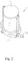
- Figs. 1-3show an induction heater 1 with a housing 2.
- the housing 2comprises a cylindrical outer chamber wall 4, e.g., made of glass, that is closed at the top by a cap 6 and at the bottom by a ceramic base part 8 and a metal base part 10.
- a cylindrical inner chamber wall 12 made, e.g., of glass,is held in a shoulder recess of the ceramic base part 8 and a shoulder recess of an inlet projection 6a of the cap 6.
- An induction coil 14is mounted about the cylindrical inner chamber wall 12 and a core 16, which can be a steel wool type material, fills the interior of the chamber formed within the cylindrical inner chamber wall 12.
- Gaskets 12a, 12bare provided at the ends of the cylindrical inner chamber wall 12 and gaskets 4a and 4b at the ends of the outer chamber wall 4 to provide air-tight sealing thereof relative to the cap 6 and ceramic base part 8, respectively.
- the ceramic base part 8contains a passage into which a terminal 20 for connection to a thermocouple 32 is received.
- the ceramic base part 8contains an opening into which an inlet piece 22 is inserted and which also connects to an inlet passage 24 of the metal base part 10 to a fitting 26 of a supply line 28.
- the cap 6has openings 6b in the inlet projection 6a and the base part 8 has a discharge passage 31 in which a thermocouple 32 is located.
- the induction heater 1is in effect a counterflow heat exchanger. Cool air from the supply line 28 passes through the inlet passage 24 and out through inlet piece 22 into the outer chamber 30 in a horizontal direction to produce a vortex flow around the induction coil 14 and inner chamber 12. As the cool air travels up chamber 30 it is preheated by the induction coil 14 which is cooled as a result. The preheated air passes through inlets 6b into the chamber formed within the cylindrical inner chamber wall 12 where it passes down through the core 16 and out of the heater 1 through discharge passage 31. Thermocouple 32 is located in the discharge passage 31 to measure the temperature of the exiting hot air to provide temperature feedback to a control circuit, an example of which is shown in Fig. 7 .
- the induction heater 1is part of a heater assembly in which it is mounted to a heater box 37, a gasket 39 providing an air tight seal between the heater 1 and heater box 37.
- a high temperature ceramic terminal block 41is supported on a spacer 43 and connected to the heater box 37 by screws 45.
- the leads 34 of the induction coil 14are connected to large surface area conducting strips 47 in the terminal block 41.
- the conducting strips 47made for example of copper, connect the induction coil 14 to the drive circuit 49.
- the large surface area conducting strips 47also provide convection cooling by ambient air, thereby enabling the drive circuit 49 to be in close proximity to the induction heater 1 without causing overheating of the drive circuit.
- a choke 51that is carried on a printed circuit board 57 having the remainder of the drive circuit 49 of Fig. 7 .
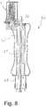
- Fig. 8shows a handheld convective soldering and rework apparatus incorporating the heater of the present invention and described above.
- the heater 1is incorporated into a hand grip 62 such that the discharge passage 31 is connected to an outflow passage 64, through which a vacuum pickup 66 extends in a conventional manner, to a discharge nozzle 68.
- the handheld convective soldering and rework apparatuscan be of any known type.
- Fig. 9shows a bench-top convective soldering and rework apparatus 70 incorporating the heater 1 of the present invention, as described above.
- the base of the heater 1is mounted on the base 72 of the bench top apparatus 70. Heated air from the discharge passage 31 is directed through the base 72 of the bench top apparatus 70 to an outflow passage 74, through which a vacuum pickup 76 extends in a conventional manner.
- the bench-top convective soldering and rework apparatuscan be of any known type.
- the heater of the inventionbeing especially well suited for use in convective soldering and rework apparatus.
- the induction heater 1preferably has an inner chamber and an outer chamber 30, a heat exchange core 16 disposed in the inner chamber, and an induction (heater) coil 14 disposed in the outer chamber 30 extending around the core 16.
- a cool air inletpreferably comprises or consists of the opening in the ceramic base part 8 and/or inlet piece 22 and/or inlet passage 24 and/or fitting 26 and/or supply line 28.
- a heated air outletpreferably comprises or consists of a through passage in the ceramic base part 8 and/or terminal 20.
- the inner chamberpreferably comprises the cool air inlet.
- the outer chamberpreferably comprises the heated air outlet.
- a flow path for the fluidis preferably provided from the cool air inlet, along the outer chamber / the chamber comprising the induction coil 41, into the inner chamber / the chamber comprising the core 16 and through the inner chamber / the chamber comprising the core 16 and through core 16 to the heated air outlet in a counterflow direction relative to the flow along the outer chamber / the chamber comprising the induction coil 41.
- the induction coil 14, also referred to as inductive heating coil or induction heater coil,can be disposed in the inner chamber and the core 16 can be placed in the outer chamber 30, the core 16 preferably surrounding the induction coil 14 interruption-free in this case such that a short circuit is formed and/or eddy currents can be induced in the core 16.
- the cool air inletpreferably forms part of the chamber comprising the inductor coil 14 while the heated air outlet preferably forms part of the chamber comprising the core 16.
- the chamberspreferably are separated from one another by the chamber wall 12.
- the chamber wall 12can be electrically insolating, dielectric and/or fluid tight.
- the chamberspreferably are fluidically connected (only) on a (face) end, in particular wherein the end is provided on a side remote or opposing to the cool air inlet and/or to the heated air outlet.
- the connection allowing the fluid or air passing form one to the other chamberpreferably is realized by cap 6 and/or inlet projection 6a.
- the induction coil 14 and/or the core 16preferably extend along the chamber wall 12, in particular adjacent to one another and/or parallel.
- magnetic fields produced by the induction heater coil 14act on the core 16 such that said core 14 is heated.
- the induction heater coil 14is arranged coaxially, concentrically, and/or overlapping at least essentially with the core.
- the heatingpreferably is achieved by an electric current which is induced in said core 16 by means of the induction heater coil 14.
- the core 16preferably comprises or consists of an electrically conductive fibrous material, preferably comprising electrically conductive fibers or filaments, like electrically conductive wool, in particular metal wool.
- the core 16preferably comprises or consists of stainless or non-corrosive material.
- the core 16preferably is configured such that eddy currents can be generated by the magnetic field which can be or is produced by the induction heater coil 14.
- electrical short circuitsare formed by the core material forming core 16.
- said electric short circuitsextend across or at least essentially perpendicular to the magnetic field lines the induction heater coil 14 generates or can generate.
- said electric short circuitsextend across or at least essentially perpendicular to a middle axis or an axis of symmetry of the induction heater coil 14.
- said fibers or filaments for that purposehave multiple electrical contact points such that the short circuits are formed.
- the heater 1 or apparatuscomprises a temperature control arrangement.
- the induction coil 14preferably is controlled by the closed-loop thermocouple temperature control arrangement which measures the temperature of the heated fluid stream as it exits the inner chamber or at the heated air outlet.
- the temperature control arrangementpreferably varies the current flowing through the induction coil 14 such that a desired temperature of the heated fluid is achieved at the heated air outlet.
- the top coverpreferably comprises or consists of cap 6 and/or inlet projection 6a.
- the temperature cylinderspreferably are formed by chamber wall 4 / housing 2 or parts thereof, and/or inner chamber wall 12.
- the inner chamberis formed within the inner chamber wall 12, and/or the outer chamber is formed between the inner chamber wall 12 and the outer chamber wall 4.
- Chamber 30preferably is the outer chamber and/or comprises the induction coil 14.
- the drive circuit 49preferably realizes or comprises the closed-loop thermocouple temperature control arrangement or parts thereof.
- the outflow passage 64preferably is fluidically connected to the heated air outlet or is formed thereby.
- the outflow passage 64can be realized by out flow passage 74 and/or can form part of rework apparatus 70.
- the inner passage of the end grippreferably is or comprises the outflow passage 64.
Landscapes
- Engineering & Computer Science (AREA)
- Mechanical Engineering (AREA)
- Physics & Mathematics (AREA)
- Electromagnetism (AREA)
- Health & Medical Sciences (AREA)
- Dermatology (AREA)
- General Health & Medical Sciences (AREA)
- General Induction Heating (AREA)
Description
- This invention relates generally to convective automated and semi-automatic rework systems for the installation and removal of electronic components with respect to a circuit board. More specifically, these components are of the leadless Area Array (or Land Grid Array) type whose means of electronic interconnection with the circuit board is by way of solder balls, solder columns or terminations on the underside of the component body.
- Representative examples of such component packages include BGAs, PBGAs, CSPs or µBGAs, CBGAs and QFNs. These components are either attached to or removed from the circuit board by heating all the solder interconnections ("solder joints")simultaneously with a heated fluid (typically air or nitrogen) to some point above solder melt temperature followed by a period of cool down to allow the solder joints to solidify during an installation process, or by separating or lifting the component from the circuit board immediately, well prior to solder solidification during a removal process.
- The heated fluid for the solder reflow process is typically provided via an air blower (at a rate of approximately 5-35 SLPM) which passes air through a heater with resistance coil heating elements, where it is heated to a temperature well above solder melt temperature (e.g., 183° C for Sn63/Pb37 alloy and 217° C for Sn96.5/Ag3.0/Cu0.5 alloy) and subsequently passed over the component, component mounting site and circuit board to effect solder reflow at the solder joints. In some cases, particularly with high thermal mass circuit boards or components, additional heat is required to be applied to the underside of the circuit board for pre-heating purposes to facilitate and/or hasten the component installation or removal process. Such underside pre-heating is provided by a secondary source of heated fluid, or an IR radiant heating system.
US 5,958,273 discloses an induction heated reactor apparatus for producing chemical products from a reaction that at least initially requires heat-input. The shown heater has a top cover and several chambers inside the heater. Further, an induction heater coil is disposed within the heater. In an inner chamber of the heater, a heat exchange core is disposed.EP 0 075 811induction coil 2 surrounds the outermost of the cylinders and serves to heat ring-like or spiral-like metal elements 7 by induction.WO 2009/050631 A1 relates to a flow-through heater based on induction heating, particularly for heating water. The heater comprises a ferromagnetic wall encasing an induction coil for heating at least a wall portion of the ferromagnetic wall.- Induction heating methods are well known in various applications such as cook-tops, household heating systems, welding and even soldering systems where a workpiece to be soldered (e.g., a steel, copper, brass or aluminum parts) is introduced within an induction coil and heated.
- However, induction heating has never before been used to heat a fluid, in particular air, for convective soldering and rework, particularly in a benchtop system specifically for convective rework and with all its attendant advantages over resistance coil heaters discussed below.
- The resistance coil heating elements typically employed in such convective reflow systems are often expensive to construct, require costly replacement of the entire element when they fail, have a high incidence of failure, are relatively inefficient at transferring heat to the fluid passing through them and require a great deal of power to operate making them relatively energy inefficient. Resistance coil heating elements are also difficult to control from a temperature standpoint inasmuch as they require relatively robust, high thermal mass construction and thus cannot cool down quickly from a higher temperature setting when a lower temperature setting is subsequently desired.
- Due to their relative inefficiency at transferring heat to the fluid (as well as the relative inefficiently of the fluid to transfer heat to the workpiece), such heaters must be overly powered which in turn requires them to be relatively dimensionally large, physically and thermally robust (resistance heating coils must be mounted to a highly heat resistant core such as ceramic or aluminum oxide) and very well insulated or isolated from the rest of the internal components of the rework system so they may withstand significant errant heating, particularly during heavy, continuous use. This also causes the physical size of the reflow head (of the rework system) to grow to disproportionate dimensions (for adequate thermal and electrical isolation) and/or subjects other delicate systems (which by necessity must be in close proximity to the heating element) to excessive heat, degradation and premature failure. A further key negative consequence of such resistance coil heating elements is their very high thermal mass, which causes the heater to take an inordinately long time to heat up from ambient temperature thus delaying throughput of the component rework process. What's more, the high thermal mass acts as a dampener or buffer to the ability of the reworks system to precisely and rapidly control the temperature of the heated fluid and thus better control the component reflow process (during component installation or removal).
- This consequence, along with the relatively inefficiency of such heaters to transfer heat to the fluid (as well as the relatively inefficiency of the fluid to transfer heat to the workpiece) as mentioned above, presents a significant challenge to achieving a high level of process control during the rework process which is essential as process requirements varies significantly across various types of circuit boards, components and electronic assemblies.
- The present invention includes a novel induction heater method and arrangement for the controlled, reliable and efficient heating of fluid in a convective rework system for the installation and removal of electronic components, particularly area array components.
- The induction heater consists of a nickel plated copper induction coil (in an LC resonant Royer oscillator circuit) around an inner glass chamber filled with a ferromagnetic stainless steel wool core through which fluid passes and is efficiently heated. The induction coil is contained within an outer glass chamber through which the ambient temperature fluid first passes before passing through the inner glass chamber and core. This not only preheats the fluid prior to passing through the steel wool (for greater thermal efficiency in the heat transfer process), but also keeps the Induction Coil cool thus protecting adjacent mechanical and electrical systems from excessive, errant heat and extending the life of the Coil itself.
- High current (-60-70 Amps), high frequency (-130 kHz) AC pulse power passes through the Induction Coil which is controlled by a closed-loop thermocouple temperature control arrangement which measures the temperature of the heated fluid stream as it exits the inner glass chamber.
- In a typical induction heating system, as current passes through the induction coil, it creates an electromagnetic field within the core, and in turn causes the core material to heat up by both Eddy (or Foucault) Currents and Magnetic Hysteresis produced therein. Heating by way of the later phenomenon is automatically governed as the material reaches its Curie point or temperature at which the core material loses its permanent magnetic properties and will heat no further due to loss of the Magnetic Hysteresis effect. This may offer the advantage of providing an additional protection against the heater running away and burning up should the primary temperature control system (the thermocouple in the exit air stream of the closed-loop temperature control system) for some reason fail.
- The induction heater of the present invention is usable in place of the resistance heater in existing reflow systems such as PACE's ThermoFlo Rework Systems (Models TF 1700 & TF 2700) as described in the PACE Worldwide brochure SMT & Area Array Rework, 2015. These systems employ traditional Convection Heaters comprised of resistance coils (mounted with respect to a ceramic substrate) through which ambient-temperature air is blown and heated to well above the solder melt temperature before reaching the component and board mounting site to effect solder reflow during a component installation or removal procedure.
- On a small scale, the induction heater of the present invention is also usable in soldering handpieces, such as PACE's ThermoJet® air pencils (Models TJ-70 and TJ-85) as the means for heating air that is delivered for installation and removal of chip components and SOTs.
- To implement the new heater of the present invention in such an existing device, besides removing the old resistance heating coil convective, or other heater, and replacing it with the new induction convection heater, circuitry to power and control it would need to be changed to one suitable for an induction heater and the control would have to be adapted to conform to how the ambient-temperature air is controlled and supplied to the respective heaters, an example of one suitable circuit being shown in
Fig. 7 of this application. - Alternatively, the inductive heater could be incorporated within the power source itself and heat the air being supplied.
- The induction heater arrangement of the present invention offers the following key advantages over the prior art:
The stainless steel core has a great deal more surface area than the resistance heater coils (in the prior art heater elements) and requires the fluid to pass through irregular channels (facilitating better fluid mixing) which both provide vastly superior heat transfer to the fluid as it passes through. - The stainless steel wool core as well as the overall induction heater is low in thermal mass, thereby allowing the rework system to come up to target temperature faster and cool off more quickly providing superior process control and faster work throughput. The quick cooldown of the heater also offers the ability of the rework system to provide an "active cooling phase" of the component and circuit board after reflow and obviates the need for an external fan to serve this function.
- The thermal and energy efficiency of the induction heater produces far less errant heat and is dimensionally smaller. This is the result of not only its low thermal mass character but also its design in which the ambient temperature fluid first passes over the induction coil itself prior to passing through the core material. The fluid first enters the outer glass chamber containing the induction coil in such a way as to create a vortex flow pattern to maximize heat transfer from the coil to the fluid (as well as more uniform cooling of the coil) before it passes through the inner glass chamber and core material.
- This results in two benefits: 1) the fluid is both preheated (prior to passing through the core material) and results in greater efficiency of heat transfer from the heater to the fluid, and 2) the induction coil is kept relatively cool thereby greatly reducing the amount of errant heat produced which could adversely affect adjacent delicate mechanical and electrical systems.
- The subsequent benefit of #3 is that such delicate mechanical and electrical systems can be safely located in close proximity to the induction heater and will not be adversely affected by errant heating which could cause them to lose their precision or reliability. A notable example of this would be the vacuum pick travel system which by operational necessity must be in close proximity to the heater and maintain very tight tolerances due to its role in alignment and placement of very fine pitch components where placement accuracies are measured in thousandths (0.001) of inches.
- In older convective rework systems with resistance coil heaters, the vacuum pick travel system had to pass very close or through the heater causing it to warp, lose its tolerances or fail. In the present invention, this problem is eliminated.
- The efficiency of the heating system provides great cost savings to the user as it uses far less power than older systems with resistance coil heaters.
- The induction heater offers far greater reliability and longer life than resistance coil heaters. There are no heating coils to burn out which can occur frequently due to the difficulty of controlling them. The stainless steel wool core, which could break down over time, is easily and quickly replaced at very little cost. Also the cooling effect of the fluid first passing over the induction coil greatly reduces thermal breakdown of the copper and nickel plating thereby extending its life.
- The induction heater's ability to efficiency transfer heat to the fluid (and subsequently to the work) can in some cases lessen or obviate the need for additional bottom pre-heating.
- The ability to locate the power circuitry in close proximity to the heater coil improves stability of the oscillator circuit and simplifies the design of RFI shielding that may be required.
- Figs. 1-3
- are exploded, perspective and longitudinal section views, respectively, of the induction heater of the induction heater assembly;
- Figs. 4
- is an exploded perspective view of an induction heater assembly in accordance with the invention;
- Figs. 5 & 6
- are plan and side views of a control board of induction heater assembly in accordance with the invention;
- Fig. 7
- shows an example of a control circuit for the induction heater;
- Fig. 8
- shows a handheld convective soldering and rework apparatus incorporating the heater of the present invention; and
- Fig. 9
- shows a bench-top convective soldering and rework apparatus incorporating the heater of the present invention.
Figs. 1-3 show aninduction heater 1 with ahousing 2. Thehousing 2 comprises a cylindricalouter chamber wall 4, e.g., made of glass, that is closed at the top by acap 6 and at the bottom by aceramic base part 8 and ametal base part 10. A cylindricalinner chamber wall 12 made, e.g., of glass, is held in a shoulder recess of theceramic base part 8 and a shoulder recess of an inlet projection 6a of thecap 6. Aninduction coil 14 is mounted about the cylindricalinner chamber wall 12 and acore 16, which can be a steel wool type material, fills the interior of the chamber formed within the cylindricalinner chamber wall 12.Gaskets 12a, 12b are provided at the ends of the cylindricalinner chamber wall 12 and gaskets 4a and 4b at the ends of theouter chamber wall 4 to provide air-tight sealing thereof relative to thecap 6 andceramic base part 8, respectively.- The
ceramic base part 8 contains a passage into which a terminal 20 for connection to athermocouple 32 is received. Theceramic base part 8 contains an opening into which aninlet piece 22 is inserted and which also connects to aninlet passage 24 of themetal base part 10 to a fitting 26 of asupply line 28. Thecap 6 has openings 6b in the inlet projection 6a and thebase part 8 has adischarge passage 31 in which athermocouple 32 is located. - The
induction heater 1 is in effect a counterflow heat exchanger. Cool air from thesupply line 28 passes through theinlet passage 24 and out throughinlet piece 22 into the outer chamber 30 in a horizontal direction to produce a vortex flow around theinduction coil 14 andinner chamber 12. As the cool air travels up chamber 30 it is preheated by theinduction coil 14 which is cooled as a result. The preheated air passes through inlets 6b into the chamber formed within the cylindricalinner chamber wall 12 where it passes down through thecore 16 and out of theheater 1 throughdischarge passage 31.Thermocouple 32 is located in thedischarge passage 31 to measure the temperature of the exiting hot air to provide temperature feedback to a control circuit, an example of which is shown inFig. 7 . - With reference to
Fig. 4 , it can be seen that theinduction heater 1 is part of a heater assembly in which it is mounted to aheater box 37, agasket 39 providing an air tight seal between theheater 1 andheater box 37. A high temperature ceramicterminal block 41 is supported on a spacer 43 and connected to theheater box 37 byscrews 45. The leads 34 of theinduction coil 14 are connected to large surface area conducting strips 47 in theterminal block 41. The conducting strips 47, made for example of copper, connect theinduction coil 14 to thedrive circuit 49. The large surface area conducting strips 47 also provide convection cooling by ambient air, thereby enabling thedrive circuit 49 to be in close proximity to theinduction heater 1 without causing overheating of the drive circuit. - Other elements of the drive circuit shown in
Figs. 4 &5 are achoke 51,capacitors NFETs 55 that are carried on a printedcircuit board 57 having the remainder of thedrive circuit 49 ofFig. 7 . Fig. 8 shows a handheld convective soldering and rework apparatus incorporating the heater of the present invention and described above. In this version, theheater 1 is incorporated into ahand grip 62 such that thedischarge passage 31 is connected to anoutflow passage 64, through which avacuum pickup 66 extends in a conventional manner, to adischarge nozzle 68. Apart from the incorporation of theheater 1, the handheld convective soldering and rework apparatus can be of any known type.Fig. 9 shows a bench-top convective soldering and reworkapparatus 70 incorporating theheater 1 of the present invention, as described above. In this case, the base of theheater 1 is mounted on thebase 72 of the benchtop apparatus 70. Heated air from thedischarge passage 31 is directed through thebase 72 of the benchtop apparatus 70 to anoutflow passage 74, through which avacuum pickup 76 extends in a conventional manner. Again, apart from the incorporation of theheater 1, the bench-top convective soldering and rework apparatus can be of any known type.- As a result of the above described construction, the various advantages described in the Summary above, can be obtained, the heater of the invention being especially well suited for use in convective soldering and rework apparatus.
- The
induction heater 1 preferably has an inner chamber and an outer chamber 30, aheat exchange core 16 disposed in the inner chamber, and an induction (heater)coil 14 disposed in the outer chamber 30 extending around thecore 16. - A cool air inlet preferably comprises or consists of the opening in the
ceramic base part 8 and/orinlet piece 22 and/orinlet passage 24 and/or fitting 26 and/orsupply line 28. - A heated air outlet preferably comprises or consists of a through passage in the
ceramic base part 8 and/orterminal 20. - The inner chamber preferably comprises the cool air inlet. The outer chamber preferably comprises the heated air outlet. A flow path for the fluid is preferably provided from the cool air inlet, along the outer chamber / the chamber comprising the
induction coil 41, into the inner chamber / the chamber comprising thecore 16 and through the inner chamber / the chamber comprising thecore 16 and throughcore 16 to the heated air outlet in a counterflow direction relative to the flow along the outer chamber / the chamber comprising theinduction coil 41. - Alternatively or additionally, the
induction coil 14, also referred to as inductive heating coil or induction heater coil, can be disposed in the inner chamber and the core 16 can be placed in the outer chamber 30, the core 16 preferably surrounding theinduction coil 14 interruption-free in this case such that a short circuit is formed and/or eddy currents can be induced in thecore 16. - The cool air inlet preferably forms part of the chamber comprising the
inductor coil 14 while the heated air outlet preferably forms part of the chamber comprising thecore 16. - The chambers preferably are separated from one another by the
chamber wall 12. Thechamber wall 12 can be electrically insolating, dielectric and/or fluid tight. - The chambers preferably are fluidically connected (only) on a (face) end, in particular wherein the end is provided on a side remote or opposing to the cool air inlet and/or to the heated air outlet. The connection allowing the fluid or air passing form one to the other chamber preferably is realized by
cap 6 and/or inlet projection 6a. - The
induction coil 14 and/or the core 16 preferably extend along thechamber wall 12, in particular adjacent to one another and/or parallel. - Preferably, magnetic fields produced by the
induction heater coil 14 act on the core 16 such that saidcore 14 is heated. - Preferably, the
induction heater coil 14 is arranged coaxially, concentrically, and/or overlapping at least essentially with the core. - The heating preferably is achieved by an electric current which is induced in said
core 16 by means of theinduction heater coil 14. - The core 16 preferably comprises or consists of an electrically conductive fibrous material, preferably comprising electrically conductive fibers or filaments, like electrically conductive wool, in particular metal wool. The core 16 preferably comprises or consists of stainless or non-corrosive material.
- The core 16 preferably is configured such that eddy currents can be generated by the magnetic field which can be or is produced by the
induction heater coil 14. - Preferably, electrical short circuits are formed by the core
material forming core 16. In particular, said electric short circuits extend across or at least essentially perpendicular to the magnetic field lines theinduction heater coil 14 generates or can generate. - Alternatively or additionally, said electric short circuits extend across or at least essentially perpendicular to a middle axis or an axis of symmetry of the
induction heater coil 14. Preferably, said fibers or filaments for that purpose have multiple electrical contact points such that the short circuits are formed. - Preferably, the
heater 1 or apparatus comprises a temperature control arrangement. - The
induction coil 14 preferably is controlled by the closed-loop thermocouple temperature control arrangement which measures the temperature of the heated fluid stream as it exits the inner chamber or at the heated air outlet. - The temperature control arrangement preferably varies the current flowing through the
induction coil 14 such that a desired temperature of the heated fluid is achieved at the heated air outlet. - The top cover preferably comprises or consists of
cap 6 and/or inlet projection 6a. - The temperature cylinders preferably are formed by
chamber wall 4 /housing 2 or parts thereof, and/orinner chamber wall 12. - Preferably, the inner chamber is formed within the
inner chamber wall 12, and/or the outer chamber is formed between theinner chamber wall 12 and theouter chamber wall 4. - Chamber 30 preferably is the outer chamber and/or comprises the
induction coil 14. - The
drive circuit 49 preferably realizes or comprises the closed-loop thermocouple temperature control arrangement or parts thereof. - The
outflow passage 64 preferably is fluidically connected to the heated air outlet or is formed thereby. - The
outflow passage 64 can be realized byout flow passage 74 and/or can form part ofrework apparatus 70. - The inner passage of the end grip preferably is or comprises the
outflow passage 64.
Claims (4)
- Induction heater (1), comprising:a base having a cool air inlet for connection to a supply of cool air and a heated air outlet,a top cover,inner and outer chamber cylinders connected in an air tight manner to the base and cover with an inner chamber being formed within the inner chamber cylinder and an outer chamber being formed between the inner and outer chamber cylinders,a heat exchange core (16) disposed in the inner chamber, wherein the core (16) is made of a steel wool material through strands of which air flowing through the inner chamber is able to pass, andan induction heater coil (14) disposed in the outer chamber extending around the inner chamber cylinder,wherein a flow path is provided from the cool air inlet, along the outer chamber, so that the air to be heated gets in contact with the induction coil, into the inner chamber and through the inner chamber and core to the heated air outlet in a counterflow direction relative to the flow along the outer chamber.
- Induction heater according to claim 1, wherein the induction heater (1) further comprises a drive circuit (49) for the induction heater (1) mounted in proximity to the induction heater (1), the drive circuit (49) being connected to the induction heater coil (14) by conductor strips having an area sufficient to provide convection cooling for protecting the drive circuit (49) from overheating.
- Induction heater according to claim 1 or 2, wherein the chamber cylinders are made of glass.
- Induction heater according to any one of the preceding claims, wherein the cool air inlet is oriented in a direction which produces to create a vortex flow pattern in the outer chamber.
Priority Applications (3)
| Application Number | Priority Date | Filing Date | Title |
|---|---|---|---|
| EP18162906.4AEP3361828B1 (en) | 2015-11-09 | 2016-11-09 | Convective soldering and rework apparatus |
| PL16020442TPL3166369T3 (en) | 2015-11-09 | 2016-11-09 | Inductive heater for area array rework system and soldering handpieces |
| PL18162906TPL3361828T3 (en) | 2015-11-09 | 2016-11-09 | Convective soldering and rework apparatus |
Applications Claiming Priority (2)
| Application Number | Priority Date | Filing Date | Title |
|---|---|---|---|
| US201562252761P | 2015-11-09 | 2015-11-09 | |
| US15/080,724US10237926B2 (en) | 2015-11-09 | 2016-03-25 | Inductive heater for area array rework system and soldering handpieces |
Related Child Applications (2)
| Application Number | Title | Priority Date | Filing Date |
|---|---|---|---|
| EP18162906.4ADivisionEP3361828B1 (en) | 2015-11-09 | 2016-11-09 | Convective soldering and rework apparatus |
| EP18162906.4ADivision-IntoEP3361828B1 (en) | 2015-11-09 | 2016-11-09 | Convective soldering and rework apparatus |
Publications (3)
| Publication Number | Publication Date |
|---|---|
| EP3166369A2 EP3166369A2 (en) | 2017-05-10 |
| EP3166369A3 EP3166369A3 (en) | 2017-08-16 |
| EP3166369B1true EP3166369B1 (en) | 2018-08-15 |
Family
ID=57326151
Family Applications (2)
| Application Number | Title | Priority Date | Filing Date |
|---|---|---|---|
| EP16020442.6ANot-in-forceEP3166369B1 (en) | 2015-11-09 | 2016-11-09 | Inductive heater for area array rework system and soldering handpieces |
| EP18162906.4ANot-in-forceEP3361828B1 (en) | 2015-11-09 | 2016-11-09 | Convective soldering and rework apparatus |
Family Applications After (1)
| Application Number | Title | Priority Date | Filing Date |
|---|---|---|---|
| EP18162906.4ANot-in-forceEP3361828B1 (en) | 2015-11-09 | 2016-11-09 | Convective soldering and rework apparatus |
Country Status (3)
| Country | Link |
|---|---|
| US (1) | US10237926B2 (en) |
| EP (2) | EP3166369B1 (en) |
| PL (2) | PL3361828T3 (en) |
Families Citing this family (4)
| Publication number | Priority date | Publication date | Assignee | Title |
|---|---|---|---|---|
| JP6906930B2 (en)* | 2016-11-24 | 2021-07-21 | 株式会社ブリヂストン | Electromagnetic induction heating device |
| CN115152323B (en)* | 2020-02-19 | 2024-10-15 | 株式会社巴川制纸所 | Heat exchanger |
| CN113115521B (en)* | 2021-03-19 | 2022-02-15 | 中国电子科技集团公司第二十九研究所 | Reworking and repairing device and method for microwave assembly bonding process integrated device |
| CN114192919B (en)* | 2021-12-03 | 2022-10-25 | 郑州科创电子有限公司 | Vacuum brazing device for aviation parts |
Family Cites Families (14)
| Publication number | Priority date | Publication date | Assignee | Title |
|---|---|---|---|---|
| US2407562A (en)* | 1942-08-17 | 1946-09-10 | Einar G Lofgren | Induction heater |
| US3685139A (en) | 1969-03-10 | 1972-08-22 | Garrett Corp | Method of brazing |
| SE442696B (en) | 1981-09-24 | 1986-01-20 | Asea Ab | DEVICE FOR HEATING OF GAS OR LIQUID MEDIA |
| US5309545A (en)* | 1990-08-27 | 1994-05-03 | Sierra Research And Technology, Inc. | Combined radiative and convective rework system |
| US5958273A (en) | 1994-02-01 | 1999-09-28 | E. I. Du Pont De Nemours And Company | Induction heated reactor apparatus |
| CN1174660C (en)* | 1994-10-24 | 2004-11-03 | 松下电器产业株式会社 | Induction heating steam generating equipment |
| US6370086B2 (en) | 1999-03-15 | 2002-04-09 | Shih-Hsiung Li | Ultrasound sensor for distance measurement |
| US6131791A (en)* | 1999-12-06 | 2000-10-17 | Hakko Corporation | Soldering and desoldering device with improved pickup device |
| DE10153368A1 (en) | 2001-10-29 | 2003-05-08 | Ikarus Solar Ag | Method of connecting metal pipe to plate in solar collector has heat for weld provided by induction in fluid fed through pipe |
| JP3993476B2 (en)* | 2002-06-20 | 2007-10-17 | 東芝テック株式会社 | Fixing device |
| KR20100085108A (en) | 2007-10-18 | 2010-07-28 | 코닌클리케 필립스 일렉트로닉스 엔.브이. | Flow-through induction heater |
| EP2689946B1 (en) | 2012-07-24 | 2018-09-05 | MAHLE Behr GmbH & Co. KG | Heating device |
| JP5541354B1 (en) | 2012-12-28 | 2014-07-09 | 千住金属工業株式会社 | Arrangement structure of gas blowing holes and soldering apparatus |
| US10273626B2 (en)* | 2015-06-01 | 2019-04-30 | Robert K. Spitz | Portable, collapsible clothes dryer |
- 2016
- 2016-03-25USUS15/080,724patent/US10237926B2/enactiveActive
- 2016-11-09EPEP16020442.6Apatent/EP3166369B1/ennot_activeNot-in-force
- 2016-11-09PLPL18162906Tpatent/PL3361828T3/enunknown
- 2016-11-09EPEP18162906.4Apatent/EP3361828B1/ennot_activeNot-in-force
- 2016-11-09PLPL16020442Tpatent/PL3166369T3/enunknown
Non-Patent Citations (1)
| Title |
|---|
| None* |
Also Published As
| Publication number | Publication date |
|---|---|
| US20170135161A1 (en) | 2017-05-11 |
| EP3166369A2 (en) | 2017-05-10 |
| EP3361828A1 (en) | 2018-08-15 |
| EP3361828B1 (en) | 2019-04-03 |
| US10237926B2 (en) | 2019-03-19 |
| EP3166369A3 (en) | 2017-08-16 |
| PL3166369T3 (en) | 2019-01-31 |
| PL3361828T3 (en) | 2019-09-30 |
Similar Documents
| Publication | Publication Date | Title |
|---|---|---|
| EP3166369B1 (en) | Inductive heater for area array rework system and soldering handpieces | |
| KR102411595B1 (en) | Heating and cooling device | |
| US6884975B2 (en) | Localized stress relief by induction heating | |
| EP0549654B1 (en) | Self-regulating heater utilizing ferro- or ferrimagnetic body | |
| US4426571A (en) | Portable electric hot air rework tool for soldering and desoldering printed circuit assemblies | |
| CA1264360A (en) | Self-heating, self-soldering bus bar | |
| EP0169885A4 (en) | Multi-zone thermal process system utilizing nonfocused infrared panel emitters. | |
| EP1954110A1 (en) | Soldering apparatus and soldering method | |
| US4431891A (en) | Arrangement for making contact between the conductor tracks of printed circuit boards with contact pins | |
| CN220698478U (en) | Induction brazing system of coplanar pressure sensor impulse tube | |
| JP2001326455A (en) | Reflow method and reflow device | |
| JPH11307927A (en) | Soldering equipment and soldering method | |
| CN100443235C (en) | Electrode and induction device for electromagnetic induction welding machine for multilayer printed circuits | |
| JP3109689B2 (en) | Reflow soldering equipment | |
| CN114433974B (en) | A resonant gap induction heating head | |
| KR20160021220A (en) | Miniaturized head for induction welding of printed circuits | |
| CN100484341C (en) | Current-collecting induction heater | |
| JP3729689B2 (en) | Reflow method and apparatus | |
| Nowottnick et al. | Developments in Vapor Phase Soldering Technology | |
| US3441706A (en) | Induction heating apparatus | |
| JP2024132729A (en) | Preheating mechanism for jet soldering device and jet soldering device | |
| JPH04339561A (en) | Preheater for automatic soldering apparatus | |
| CN106424997B (en) | Double-casing motor main pole coil welding method and its fixture used | |
| RU2287230C2 (en) | Gas- and vacuum-tight heat-insulated chamber for induction heating device | |
| JPH11186707A (en) | Apparatus and method for soldering |
Legal Events
| Date | Code | Title | Description |
|---|---|---|---|
| PUAI | Public reference made under article 153(3) epc to a published international application that has entered the european phase | Free format text:ORIGINAL CODE: 0009012 | |
| AK | Designated contracting states | Kind code of ref document:A2 Designated state(s):AL AT BE BG CH CY CZ DE DK EE ES FI FR GB GR HR HU IE IS IT LI LT LU LV MC MK MT NL NO PL PT RO RS SE SI SK SM TR | |
| AX | Request for extension of the european patent | Extension state:BA ME | |
| RIN1 | Information on inventor provided before grant (corrected) | Inventor name:NAIR, RAMGOPAL Inventor name:MILLER, THOMAS WAYNE | |
| PUAL | Search report despatched | Free format text:ORIGINAL CODE: 0009013 | |
| AK | Designated contracting states | Kind code of ref document:A3 Designated state(s):AL AT BE BG CH CY CZ DE DK EE ES FI FR GB GR HR HU IE IS IT LI LT LU LV MC MK MT NL NO PL PT RO RS SE SI SK SM TR | |
| AX | Request for extension of the european patent | Extension state:BA ME | |
| RIC1 | Information provided on ipc code assigned before grant | Ipc:B23K 1/012 20060101ALI20170712BHEP Ipc:H05B 6/10 20060101AFI20170712BHEP | |
| 17P | Request for examination filed | Effective date:20180212 | |
| RBV | Designated contracting states (corrected) | Designated state(s):AL AT BE BG CH CY CZ DE DK EE ES FI FR GB GR HR HU IE IS IT LI LT LU LV MC MK MT NL NO PL PT RO RS SE SI SK SM TR | |
| GRAP | Despatch of communication of intention to grant a patent | Free format text:ORIGINAL CODE: EPIDOSNIGR1 | |
| INTG | Intention to grant announced | Effective date:20180328 | |
| GRAS | Grant fee paid | Free format text:ORIGINAL CODE: EPIDOSNIGR3 | |
| GRAA | (expected) grant | Free format text:ORIGINAL CODE: 0009210 | |
| AK | Designated contracting states | Kind code of ref document:B1 Designated state(s):AL AT BE BG CH CY CZ DE DK EE ES FI FR GB GR HR HU IE IS IT LI LT LU LV MC MK MT NL NO PL PT RO RS SE SI SK SM TR | |
| REG | Reference to a national code | Ref country code:CH Ref legal event code:EP Ref country code:GB Ref legal event code:FG4D Ref country code:AT Ref legal event code:REF Ref document number:1031304 Country of ref document:AT Kind code of ref document:T Effective date:20180815 | |
| REG | Reference to a national code | Ref country code:IE Ref legal event code:FG4D | |
| REG | Reference to a national code | Ref country code:DE Ref legal event code:R096 Ref document number:602016004635 Country of ref document:DE | |
| REG | Reference to a national code | Ref country code:NL Ref legal event code:MP Effective date:20180815 | |
| REG | Reference to a national code | Ref country code:LT Ref legal event code:MG4D | |
| REG | Reference to a national code | Ref country code:AT Ref legal event code:MK05 Ref document number:1031304 Country of ref document:AT Kind code of ref document:T Effective date:20180815 | |
| PG25 | Lapsed in a contracting state [announced via postgrant information from national office to epo] | Ref country code:NL Free format text:LAPSE BECAUSE OF FAILURE TO SUBMIT A TRANSLATION OF THE DESCRIPTION OR TO PAY THE FEE WITHIN THE PRESCRIBED TIME-LIMIT Effective date:20180815 Ref country code:LT Free format text:LAPSE BECAUSE OF FAILURE TO SUBMIT A TRANSLATION OF THE DESCRIPTION OR TO PAY THE FEE WITHIN THE PRESCRIBED TIME-LIMIT Effective date:20180815 Ref country code:GR Free format text:LAPSE BECAUSE OF FAILURE TO SUBMIT A TRANSLATION OF THE DESCRIPTION OR TO PAY THE FEE WITHIN THE PRESCRIBED TIME-LIMIT Effective date:20181116 Ref country code:BG Free format text:LAPSE BECAUSE OF FAILURE TO SUBMIT A TRANSLATION OF THE DESCRIPTION OR TO PAY THE FEE WITHIN THE PRESCRIBED TIME-LIMIT Effective date:20181115 Ref country code:SE Free format text:LAPSE BECAUSE OF FAILURE TO SUBMIT A TRANSLATION OF THE DESCRIPTION OR TO PAY THE FEE WITHIN THE PRESCRIBED TIME-LIMIT Effective date:20180815 Ref country code:NO Free format text:LAPSE BECAUSE OF FAILURE TO SUBMIT A TRANSLATION OF THE DESCRIPTION OR TO PAY THE FEE WITHIN THE PRESCRIBED TIME-LIMIT Effective date:20181115 Ref country code:AT Free format text:LAPSE BECAUSE OF FAILURE TO SUBMIT A TRANSLATION OF THE DESCRIPTION OR TO PAY THE FEE WITHIN THE PRESCRIBED TIME-LIMIT Effective date:20180815 Ref country code:IS Free format text:LAPSE BECAUSE OF FAILURE TO SUBMIT A TRANSLATION OF THE DESCRIPTION OR TO PAY THE FEE WITHIN THE PRESCRIBED TIME-LIMIT Effective date:20181215 Ref country code:RS Free format text:LAPSE BECAUSE OF FAILURE TO SUBMIT A TRANSLATION OF THE DESCRIPTION OR TO PAY THE FEE WITHIN THE PRESCRIBED TIME-LIMIT Effective date:20180815 Ref country code:FI Free format text:LAPSE BECAUSE OF FAILURE TO SUBMIT A TRANSLATION OF THE DESCRIPTION OR TO PAY THE FEE WITHIN THE PRESCRIBED TIME-LIMIT Effective date:20180815 | |
| PG25 | Lapsed in a contracting state [announced via postgrant information from national office to epo] | Ref country code:AL Free format text:LAPSE BECAUSE OF FAILURE TO SUBMIT A TRANSLATION OF THE DESCRIPTION OR TO PAY THE FEE WITHIN THE PRESCRIBED TIME-LIMIT Effective date:20180815 Ref country code:HR Free format text:LAPSE BECAUSE OF FAILURE TO SUBMIT A TRANSLATION OF THE DESCRIPTION OR TO PAY THE FEE WITHIN THE PRESCRIBED TIME-LIMIT Effective date:20180815 Ref country code:LV Free format text:LAPSE BECAUSE OF FAILURE TO SUBMIT A TRANSLATION OF THE DESCRIPTION OR TO PAY THE FEE WITHIN THE PRESCRIBED TIME-LIMIT Effective date:20180815 | |
| PG25 | Lapsed in a contracting state [announced via postgrant information from national office to epo] | Ref country code:IT Free format text:LAPSE BECAUSE OF FAILURE TO SUBMIT A TRANSLATION OF THE DESCRIPTION OR TO PAY THE FEE WITHIN THE PRESCRIBED TIME-LIMIT Effective date:20180815 Ref country code:EE Free format text:LAPSE BECAUSE OF FAILURE TO SUBMIT A TRANSLATION OF THE DESCRIPTION OR TO PAY THE FEE WITHIN THE PRESCRIBED TIME-LIMIT Effective date:20180815 Ref country code:RO Free format text:LAPSE BECAUSE OF FAILURE TO SUBMIT A TRANSLATION OF THE DESCRIPTION OR TO PAY THE FEE WITHIN THE PRESCRIBED TIME-LIMIT Effective date:20180815 Ref country code:CZ Free format text:LAPSE BECAUSE OF FAILURE TO SUBMIT A TRANSLATION OF THE DESCRIPTION OR TO PAY THE FEE WITHIN THE PRESCRIBED TIME-LIMIT Effective date:20180815 Ref country code:ES Free format text:LAPSE BECAUSE OF FAILURE TO SUBMIT A TRANSLATION OF THE DESCRIPTION OR TO PAY THE FEE WITHIN THE PRESCRIBED TIME-LIMIT Effective date:20180815 | |
| REG | Reference to a national code | Ref country code:DE Ref legal event code:R097 Ref document number:602016004635 Country of ref document:DE | |
| PG25 | Lapsed in a contracting state [announced via postgrant information from national office to epo] | Ref country code:SK Free format text:LAPSE BECAUSE OF FAILURE TO SUBMIT A TRANSLATION OF THE DESCRIPTION OR TO PAY THE FEE WITHIN THE PRESCRIBED TIME-LIMIT Effective date:20180815 Ref country code:SM Free format text:LAPSE BECAUSE OF FAILURE TO SUBMIT A TRANSLATION OF THE DESCRIPTION OR TO PAY THE FEE WITHIN THE PRESCRIBED TIME-LIMIT Effective date:20180815 Ref country code:DK Free format text:LAPSE BECAUSE OF FAILURE TO SUBMIT A TRANSLATION OF THE DESCRIPTION OR TO PAY THE FEE WITHIN THE PRESCRIBED TIME-LIMIT Effective date:20180815 | |
| PLBE | No opposition filed within time limit | Free format text:ORIGINAL CODE: 0009261 | |
| STAA | Information on the status of an ep patent application or granted ep patent | Free format text:STATUS: NO OPPOSITION FILED WITHIN TIME LIMIT | |
| 26N | No opposition filed | Effective date:20190516 | |
| PG25 | Lapsed in a contracting state [announced via postgrant information from national office to epo] | Ref country code:MC Free format text:LAPSE BECAUSE OF FAILURE TO SUBMIT A TRANSLATION OF THE DESCRIPTION OR TO PAY THE FEE WITHIN THE PRESCRIBED TIME-LIMIT Effective date:20180815 Ref country code:LU Free format text:LAPSE BECAUSE OF NON-PAYMENT OF DUE FEES Effective date:20181109 | |
| REG | Reference to a national code | Ref country code:BE Ref legal event code:MM Effective date:20181130 | |
| REG | Reference to a national code | Ref country code:IE Ref legal event code:MM4A | |
| PG25 | Lapsed in a contracting state [announced via postgrant information from national office to epo] | Ref country code:SI Free format text:LAPSE BECAUSE OF FAILURE TO SUBMIT A TRANSLATION OF THE DESCRIPTION OR TO PAY THE FEE WITHIN THE PRESCRIBED TIME-LIMIT Effective date:20180815 | |
| PG25 | Lapsed in a contracting state [announced via postgrant information from national office to epo] | Ref country code:IE Free format text:LAPSE BECAUSE OF NON-PAYMENT OF DUE FEES Effective date:20181109 | |
| PG25 | Lapsed in a contracting state [announced via postgrant information from national office to epo] | Ref country code:BE Free format text:LAPSE BECAUSE OF NON-PAYMENT OF DUE FEES Effective date:20181130 | |
| PG25 | Lapsed in a contracting state [announced via postgrant information from national office to epo] | Ref country code:MT Free format text:LAPSE BECAUSE OF NON-PAYMENT OF DUE FEES Effective date:20181109 | |
| PGFP | Annual fee paid to national office [announced via postgrant information from national office to epo] | Ref country code:FR Payment date:20191120 Year of fee payment:4 Ref country code:PL Payment date:20191106 Year of fee payment:4 | |
| PG25 | Lapsed in a contracting state [announced via postgrant information from national office to epo] | Ref country code:TR Free format text:LAPSE BECAUSE OF FAILURE TO SUBMIT A TRANSLATION OF THE DESCRIPTION OR TO PAY THE FEE WITHIN THE PRESCRIBED TIME-LIMIT Effective date:20180815 | |
| PG25 | Lapsed in a contracting state [announced via postgrant information from national office to epo] | Ref country code:PT Free format text:LAPSE BECAUSE OF FAILURE TO SUBMIT A TRANSLATION OF THE DESCRIPTION OR TO PAY THE FEE WITHIN THE PRESCRIBED TIME-LIMIT Effective date:20180815 | |
| PG25 | Lapsed in a contracting state [announced via postgrant information from national office to epo] | Ref country code:MK Free format text:LAPSE BECAUSE OF NON-PAYMENT OF DUE FEES Effective date:20180815 Ref country code:CY Free format text:LAPSE BECAUSE OF FAILURE TO SUBMIT A TRANSLATION OF THE DESCRIPTION OR TO PAY THE FEE WITHIN THE PRESCRIBED TIME-LIMIT Effective date:20180815 Ref country code:HU Free format text:LAPSE BECAUSE OF FAILURE TO SUBMIT A TRANSLATION OF THE DESCRIPTION OR TO PAY THE FEE WITHIN THE PRESCRIBED TIME-LIMIT; INVALID AB INITIO Effective date:20161109 | |
| REG | Reference to a national code | Ref country code:CH Ref legal event code:PL | |
| PG25 | Lapsed in a contracting state [announced via postgrant information from national office to epo] | Ref country code:LI Free format text:LAPSE BECAUSE OF NON-PAYMENT OF DUE FEES Effective date:20191130 Ref country code:CH Free format text:LAPSE BECAUSE OF NON-PAYMENT OF DUE FEES Effective date:20191130 | |
| PG25 | Lapsed in a contracting state [announced via postgrant information from national office to epo] | Ref country code:FR Free format text:LAPSE BECAUSE OF NON-PAYMENT OF DUE FEES Effective date:20201130 | |
| PGFP | Annual fee paid to national office [announced via postgrant information from national office to epo] | Ref country code:DE Payment date:20211122 Year of fee payment:6 Ref country code:GB Payment date:20211119 Year of fee payment:6 | |
| PG25 | Lapsed in a contracting state [announced via postgrant information from national office to epo] | Ref country code:PL Free format text:LAPSE BECAUSE OF NON-PAYMENT OF DUE FEES Effective date:20201109 | |
| REG | Reference to a national code | Ref country code:DE Ref legal event code:R119 Ref document number:602016004635 Country of ref document:DE | |
| GBPC | Gb: european patent ceased through non-payment of renewal fee | Effective date:20221109 | |
| PG25 | Lapsed in a contracting state [announced via postgrant information from national office to epo] | Ref country code:GB Free format text:LAPSE BECAUSE OF NON-PAYMENT OF DUE FEES Effective date:20221109 Ref country code:DE Free format text:LAPSE BECAUSE OF NON-PAYMENT OF DUE FEES Effective date:20230601 |