EP3166258B1 - System and method for configuring a network for an aircraft or spacecraft - Google Patents
System and method for configuring a network for an aircraft or spacecraftDownload PDFInfo
- Publication number
- EP3166258B1 EP3166258B1EP15193751.3AEP15193751AEP3166258B1EP 3166258 B1EP3166258 B1EP 3166258B1EP 15193751 AEP15193751 AEP 15193751AEP 3166258 B1EP3166258 B1EP 3166258B1
- Authority
- EP
- European Patent Office
- Prior art keywords
- slave devices
- slave
- slave device
- delay period
- data packets
- Prior art date
- Legal status (The legal status is an assumption and is not a legal conclusion. Google has not performed a legal analysis and makes no representation as to the accuracy of the status listed.)
- Active
Links
Images


Classifications
- H—ELECTRICITY
- H04—ELECTRIC COMMUNICATION TECHNIQUE
- H04L—TRANSMISSION OF DIGITAL INFORMATION, e.g. TELEGRAPHIC COMMUNICATION
- H04L12/00—Data switching networks
- H04L12/28—Data switching networks characterised by path configuration, e.g. LAN [Local Area Networks] or WAN [Wide Area Networks]
- H04L12/40—Bus networks
- H04L12/403—Bus networks with centralised control, e.g. polling
- H—ELECTRICITY
- H04—ELECTRIC COMMUNICATION TECHNIQUE
- H04L—TRANSMISSION OF DIGITAL INFORMATION, e.g. TELEGRAPHIC COMMUNICATION
- H04L41/00—Arrangements for maintenance, administration or management of data switching networks, e.g. of packet switching networks
- H04L41/08—Configuration management of networks or network elements
- H04L41/0803—Configuration setting
- H04L41/0813—Configuration setting characterised by the conditions triggering a change of settings
- H04L41/0816—Configuration setting characterised by the conditions triggering a change of settings the condition being an adaptation, e.g. in response to network events
- H—ELECTRICITY
- H04—ELECTRIC COMMUNICATION TECHNIQUE
- H04L—TRANSMISSION OF DIGITAL INFORMATION, e.g. TELEGRAPHIC COMMUNICATION
- H04L7/00—Arrangements for synchronising receiver with transmitter
- H04L7/0016—Arrangements for synchronising receiver with transmitter correction of synchronization errors
- H04L7/0033—Correction by delay
- H04L7/0041—Delay of data signal
- H—ELECTRICITY
- H04—ELECTRIC COMMUNICATION TECHNIQUE
- H04L—TRANSMISSION OF DIGITAL INFORMATION, e.g. TELEGRAPHIC COMMUNICATION
- H04L12/00—Data switching networks
- H04L12/28—Data switching networks characterised by path configuration, e.g. LAN [Local Area Networks] or WAN [Wide Area Networks]
- H04L12/40—Bus networks
- H04L2012/40267—Bus for use in transportation systems
- H04L2012/4028—Bus for use in transportation systems the transportation system being an aircraft
- H—ELECTRICITY
- H04—ELECTRIC COMMUNICATION TECHNIQUE
- H04L—TRANSMISSION OF DIGITAL INFORMATION, e.g. TELEGRAPHIC COMMUNICATION
- H04L67/00—Network arrangements or protocols for supporting network services or applications
- H04L67/01—Protocols
- H04L67/12—Protocols specially adapted for proprietary or special-purpose networking environments, e.g. medical networks, sensor networks, networks in vehicles or remote metering networks
Definitions
- the present applicationrelates to a network for an aircraft or spacecraft, comprising a master device and a plurality of slave devices connected in series in a daisy-chain arrangement, to an aircraft comprising such a network, and to a method of configuring such a network.
- daisy-chain topology or arrangementis used in many applications when setting up data networks.
- data networksare used in aircraft, such as, e.g., aircraft cabin electronic networks.
- aircraftsuch as, e.g., aircraft cabin electronic networks.
- network devices or nodesto or from the network, and it is desirable to keep the reconfiguration work at a minimum.
- the various network devices or nodesare connected in series such that they are arranged one after the other. Messages are transmitted along the series by forwarding the messages from network device to network device until the target network device is reached.
- the daisy-chain arrangementcomprises at one of its ends a master device and a plurality of slave devices connected to the master device.
- the master devicetransmits polling messages to the slave devices, wherein the slave devices are addressed by separate polling messages and one after the other in a defined order or sequence. This polling is repeated continuously.
- Each of the slave devicesanalyzes the received polling messages in order to determine whether it is the intended recipient of the polling message, and transmits a response message to the master device if it is the intended recipient. Otherwise, the polling message is forwarded to the next slave device, if present.
- each polling messagestarts the transmission phase of the slave device, which is the intended recipient of the respective polling message.
- US 2006/086893 A1discloses a system and method for communicating between serially connected electrical devices of a network.
- the networkincludes a series of electrical devices, and fiber optic connectors between electrical devices of the series of electrical devices forming a closed communication ring in which output of each electrical device is communicatively connected to input of a subsequent electrical device of the series of electrical devices.
- a network for an aircraft or spacecraftcomprises a master device and a plurality of slave devices.
- the master device and the slave devicesare connected in series in a daisy-chain arrangement using, e.g., one or more wires between adjacent devices.
- the master deviceis connected to a first one of the slave devices, and the remaining slave devices - up to a last one of the slave devices - are connected in series to the first slave device.
- Each of the slave deviceshas an associated identifier or address taken from a predetermined ordered sequence of identifiers and uniquely identifying the respective slave device among the plurality of slave devices.
- the identifiersmay be numbers.
- the master deviceis adapted to transmit periodically, i.e., in predetermined time intervals, polling data packets in a downstream direction along the series of slave devices.
- Each of the polling data packetsincludes one and only one identifier and, in particular, the identifier of one and only one of the slave devices, and may optionally also include user data for the slave device addressed by the identifier. However, as will be explained below it may also be preferable if some of the polling data packets include a predefined identifier which is not associated with any of the slave devices.
- the master devicetransmits the polling data packets in successive sequences, wherein each of these sequences of polling data packets includes for each of the slave devices one and only one polling data packet, i.e., one and only one polling data packet including the identifier of the respective slave device. Further, each of the sequences of polling data packets includes the polling data packets in the order defined by the predetermined sequence of identifiers, so that the slave devices are polled in the order corresponding to the order of the identifiers, which is typically not the order of the slave devices along the chain. Each of the polling data packets is preferably transmitted in another time slot.
- successive sequences of polling data packetsare preferably transmitted immediately after each other, so that the periodicity of the transmission of polling data packets is maintained between the sequences, i.e., the same predetermined polling time interval exists between each two successive polling data packets within a sequence and between the last polling data packet of a one sequence and the first polling data packet of the next sequence.
- each of the slave devicescomprises a first data interface by means of which it is connected - depending on whether it is the first slave device or another slave device in the series of slave devices - to the master device or to an adjacent slave device in an upstream direction, a second data interface by means of which it is connected to an adjacent slave device in the downstream direction (if present, i.e., if it is not already the last slave device), and a programmable or non-programmable processing unit connected to the first and second data interfaces.
- Each of the first and second data interfacesis a bidirectional or preferably full-duplex data interface allowing input of data to and output of data from the respective slave device.
- the first and second data interfacespreferably comprise one or more respective terminals to which one or more wire can be coupled.
- the processing unitis adapted to compare, for each polling data packet received on the first data interface, the identifier of the slave device to which the respective processing unit belongs with the identifier included in the respective polling data packet. If it is determined that the two identifiers match, the processing unit outputs on the first data interface a response data packet, which may be generated by the processing unit or another component of the slave device, to the master device, i.e., along the sequence of slave devices in the direction towards the master device. Further, the polling data packet is preferably output on the second data interface. In any case, if the two identifiers do not match the polling data packet is output on the second data interface.
- the processing unitis further adapted to forward response data packets received on the second data interface to the first data interface, i.e., the response data packets received from downstream slave devices are forwarded towards the master device.
- the processing unit of each of the slave devicescomprises an adjustable time delay element which is adapted to delay the output of the response data packets by an adjustable delay period, so that the output of each response data packet output by the respective slave device in response to receipt of a polling data packet having an identifier matching the identifier of the respective slave device is delayed.
- the timing of the output of the response data packets by a slave deviceis determined by the usual processing delay and by the adjustable delay period. It should be noted that the delay is not applied to response data packets received by a slave device on its second data interface from a downstream slave device and forwarded to the first data interface.
- the delay periodis set to a value which depends on the relative position of the respective slave device in the daisy-chain arrangement with respect to the remaining slave devices of the daisy-chain arrangement, but is preferably independent of the identifier of the slave device.
- the dependence between the value and the relative positionis such that the delay period continuously decreases from slave device to slave device starting from the first slave device and ending at the last slave device.
- the time delay element of each of the slave devicesincludes a buffer memory.
- the processing unitis then adapted to buffer the response data packet in the buffer memory for the respective delay period.
- the buffering timemay be controlled by, e.g., a timer included in or associated with the processing unit.
- time delay element of each of the slave devicesis adapted to delay generation of the response data packet by the processing unit by the respective delay period.
- the time delay elementmay be a physical element or a function implemented in the processing unit.
- each of the slave devicesis adapted to receive a measure of the relative position of the respective slave device and to automatically determine and set the adjustable delay period as a predetermined function of the received measure.
- the measuremay be received by manual input by an operator or by control data packets transmitted by the master device or another network entity.
- the slave devicesare operable to automatically determine the measure, such as, e.g., the relative position itself.
- the processing unit of each of the slave devicesis adapted to measure the time periods between outputting the polling data packets on the second data interface and receiving the corresponding response data packets, to determine the maximum measured time period and to automatically set the adjustable delay period based on the determined maximum. Due to the fact that the maximum measured time period depends on the number of slave devices between the slave device at issue and the last slave device, i.e., the number of slave devices following the slave device at issue, the maximum measured time period is a measure of the relative position of the respective slave device in the series of slave devices. This measure is particularly simple to determine autonomously by a slave device.
- the processing unitis adapted to set the adjustable delay period to the determined maximum time period, but it may also be advantageous to set it to a higher value, e.g., to a slightly higher value in order to account for possible jitter.
- the above processis carried out continuously or intermittently in order to be able to immediately react to the addition of a slave device, the removal of a slave device, or a malfunction of a slave device.
- the slave devicesare preferably constructed such that they include a bypass circuit which is activated in case of a malfunction.
- the processing unit of each of the slave devicesis adapted to compare the determined delay period with a predefined maximum delay period, and to set the adjustable delay period to the predefined maximum delay period if the determined delay period exceeds the predefined maximum delay period.
- the predefined maximum delay periodmay correspond to the time period between successive polling data packets, or may be selected based as a function of a maximum number of slave devices chosen at design time and the time period between successive polling data packets. In this manner it can be prevented that an indefinite delay period is set in the case of an error in the downstream transmission of polling data packets and/or the upstream transmission of the response data packets.
- the predefined maximum delay perioddetermines the maximum possible number of slave devices, because the maximum response time measured by the slave devices increases when the number of slave devices increases, and may be suitably set at design time. It is particularly preferred if the predefined maximum delay period is smaller than the time interval between successive polling data packets in the sequences of polling data packets.
- each of the slave devicesis adapted to set the delay period to zero if it is determined on the basis of the measure that the slave device is the last slave device in the series of slave devices.
- each sequence of polling data packetsincludes at the end or at the beginning thereof a special polling data packet including a predefined identifier, which is included in the sequence of identifiers and is not associated with any of the slave devices.
- the processing unit of each of the slave devicesis then adapted to identify the special polling data packets upon receipt on the first data interface, to forward them to the second data interface, but to not output a response data packet.
- special polling data packetsmay be suitable to prevent collisions of response data packets transmitted by different slave devices in the upstream direction.
- each of the slave devicescomprises or is a field programmable gate array (FPGA) .
- FPGAfield programmable gate array
- the network according to each of the above embodimentsmay be advantageously part of an aircraft or spacecraft.
- itcan constitute or be part of the aircraft cabin electronic network.
- a method of configuring a network for an aircraft or spacecraftcomprises providing a network according to any of the above-described embodiments, adding a further slave device to the daisy-chain arrangement at an arbitrary position in the series of slave devices, and setting, for each of the slave devices, the delay period to a value depending on the relative position of the respective slave device in the daisy-chain arrangement with respect to the remaining slave devices of the daisy-chain arrangement, such that the delay period continuously decreases from slave device to slave device starting from the first slave device and ending at the last slave device.
- the further slave deviceis of the same above-described construction and configuration as the slave devices already present in the daisy-chain arrangement.
- the further slave devicehas an associated identifier taken from the same predetermined ordered sequence of identifiers and uniquely identifying the further slave device among the plurality of slave devices after having added it to the daisy-chain arrangement.
- the present inventionalso provides a method of transmitting data comprising the steps of providing a network having the features of any of the above-described embodiments and of carrying out the various steps described in detail above.
- the network 1 shown in Figure 1acomprises a master device 2 and a plurality of three slave devices 3a, 3b, 3c.
- the three slave devices 3a, 3b, 3care connected in series with the master device 2, such that the slave device 3a is directly connected to the master device 2, the slave device 3b is connected to the slave device 3a, and the slave device 3c is in turn connected to the slave device 3b.
- the four devices 2, 3a, 3b, 3care, thus, connected in series in a daisy-chain arrangement with the master device 2 at the head of the arrangement.
- Each of the slave devices 3a-3ccomprises a first data interface 4 and a second data interface 5, by means of which it is coupled to the adjacent upstream device and the adjacent downstream device, respectively, if available.
- the downstream directionis the direction of data transmitted by the master device along the daisy-chain arrangement in the direction towards the last slave device 3c
- the upstream directionis the direction from the slave devices towards the master device 2.
- the slave devices 3a-3cfurther each include a processing unit 6 which, in turn, comprises a time delay element 7.
- the processing unit 6is connected to the first and second data interfaces 4, 5 of the respective slave device 3a-3c.
- each of the slave devices 3a-3chas associated therewith a identifier 10 in the form of, e.g., an integer number.
- the master device 2which comprises a processing or control unit 24 adapted to enable it to carry out the various described steps and functions, periodically transmits polling data packets 8, each including an identifier 10 of one of the slave devices 3a-3c, in order to successively poll one after the other the slave devices 2 in the order determined by their identifiers 10.
- the processing unit 6 of each of the slave devices 3a-3cis adapted to determine whether a received polling data packet 8 includes the identifier 10 of the respective slave device 3a-3c, and to forward the polling data packet 8 to the next slave device 3a-3c if the identifiers do not match.
- the processing unit 6determines whether they match the processing unit 6 match the processing unit 6 match the processing unit 6 generates a response data packet 9 and transmit it via its first data interface 4 towards the master device 2.
- the response data packets 9are forwarded from slave device to slave device to the master device 2 in a manner similar to the manner of forwarding the polling data packets 8.
- the polling data packets 8may also be used to transport actual user data from the master device 2 to the slave devices 3a, 3b, 3c. In that case, the arrows representing the polling data packets 8 would have to have a larger width than shown in the drawings, depending on the amount of data transported.
- FIG. 1bshows the same network after changing the order of the slave devices 3a-3c.
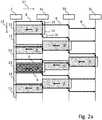
- FIG 2aa timing diagram is shown, in which the horizontal axis 11 indicates the position of the master device 2 and the slave devices 3a-3c in the daisy-chain arrangement, and the vertical axis 12 is the time axis. As indicated in Figure 2a , the time axis 12 is divided into a plurality of successive time slots 13, at the beginning of each of which the master device 2 transmits a polling data packet 8 along the chain.
- the first polling data packetincludes the identifier 10 of the slave device 3a (the identifier in this example is "1")
- the second polling data packetincludes the identifier 10 of the slave device 3b (the identifier in this example is "2")
- the third polling data packetincludes the identifier 10 of the slave device 3c (the identifier in this example is "3"), and then the sequence is repeated for the next polling data packets.
- the first polling data packet 8is received by the slave device 3a, which recognizes that it is addressed by the first polling data packet 8 and, therefore, generates and transmits a response data packet 9 over a time period 14, which is smaller than the corresponding time slot 13. Due to the processing necessary for the slave device 3a to recognize the first polling data packet 8 and to generate the response data packet 9, the transmission of the response data packet 9 is delayed by a processing delay period 15. Further, the first polling data packet 8 is forwarded to the next slave device 3b in the manner described below for the second data packet 8 at the first slave device 3a.
- the second polling data packet 8is likewise received by the slave device 3a, which recognizes, however, that it is addressed by the second polling data packet 8 and, therefore, does not generate and transmit a response data packet 9. Rather, the second polling data packet 8 is forwarded to the slave device 3b, which is the next slave device in the series of slave devices 3a-3c. Due to the processing necessary for the slave device 3a to recognize the second polling data packet 8 and to effect forwarding, the transmission of the second polling data packet 8 by the slave device 3a is delayed by a hop delay period 16, which, in the example shown is identical to the processing delay 15. The same hop delay 16 also occurs in the opposite direction when forwarding the response data packets 9 by a slave device 3a-3c.
- the response data packet 9 transmitted by the slave device 3a in response to the fourth polling data packet 8collides with the response data packet 9 transmitted earlier by the slave device 3c in response to the third polling data packet 8.
- the collision zone 17is indicated by dark shading.
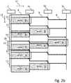
- the collision 17can be avoided in this example by adding a special time slot 18, at the beginning of which a polling data packet 8 addressed to none of the slave devices 3a-3c is transmitted, so that none of the slave devices 3a-3c respond thereto.
- the special polling data packet 8may include the identifier "0".
- the special time slot 18does not serve to prevent a collision 17 if the order of the slave devices 3a-3c is changed to the one shown in Figure 1b .
- the adjustable delay element 7 included in each of the processing units 6is adjusted for each of the slave devices 3a-3c such that before transmitting the generated response data packet 9 the processing unit 6 waits for an adjustable delay period 19.
- the adjustmentis made in such a manner that for the first slave device 3c in the daisy-chain arrangement when viewed from the master device 2 the largest delay period 19 is chosen, and the delay period 19 continuously decreases along the chain until it is zero for the last slave device 3b.
- any collisionis prevented, in the example illustrated even without providing for a special time slot.
- the use of the available upstream bandwidthis considerably increased as compared to Figures 2a , 2b and 3a , because the upstream transmissions are shifted in time to be spaced closer to each other.
- FIG. 4shows a schematic block diagram of an embodiment of a slave device 3a, 3b, 3c including the processing unit 6 implemented as a field programmable gate array (FPGA), and comprising the first data interface 4 and the second data interface 5, by means of which it is coupled to the chain in the upstream direction and the downstream direction, respectively, i.e., to one or more data lines extending between the respective slave device 3a, 3b, 3c and the immediately adjacent device or devices 2, 3a, 3b, 3c.
- FPGAfield programmable gate array
- the processing unit 6includes a receiving element 20 adapted to receive data from the chain and a transmitting element 21 adapted to transmit data on the chain.
- Received polling data packets 8 not addressed to the slave device 3a, 3b, 3care simply forwarded in the downstream direction by a downstream forwarding element 22, and response data packets 9 received from downstream slave devices are forwarded in the upstream direction by an upstream forwarding element 23.
- the time delay element 7, which is included in this example in the processing unit 6,determines for each received polling data packet 8 not addressed to the slave device 3a, 3b, 3c and forwarded in the downstream direction whether a corresponding response data packet 9 is received and what is the delay between forwarding the polling data packet 8 and receiving the response data packet 9.
- the time delay element 7is adapted to determine the maximum delay, to set the delay period 19 as described above, and to control the transmitting element 21 to delay transmission of response data packets 9 generated by the slave device 3a, 3b, 3c by the set delay period 19.
- FIG. 5is a flow diagram schematically illustrating a method of configuring a network for an aircraft or spacecraft.
- a network 1 having the above-described configurationis provided.
- a further slave device (3a, 3b, 3c)is added to the daisy-chain arrangement at an arbitrary position in the series of slave devices (3a, 3b, 3c).
- the further slave device (3a, 3b, 3c)is of the same above-described construction and configuration as the slave devices (3a, 3b, 3c) already present in the daisy-chain arrangement.
- the further slave device (3a, 3b, 3c)has an associated identifier taken from the same predetermined ordered sequence of identifiers and uniquely identifying the further slave device (3a, 3b, 3c) among the plurality of slave devices (3a, 3b, 3c), including the ones already added it to the daisy-chain arrangement.
- step 27for each of the slave devices (3a, 3b, 3c), the delay period (19) is set in the above-described manner to a value depending on the relative position of the respective slave device (3a, 3b, 3c) in the daisy-chain arrangement with respect to the remaining slave devices (3a, 3b, 3c) of the daisy-chain arrangement, such that the delay period (19) continuously decreases from slave device (3a, 3b, 3c) to slave device (3a, 3b, 3c) starting from the first slave device (3a, 3b, 3c) and ending at the last slave device (3a, 3b, 3c).
Landscapes
- Engineering & Computer Science (AREA)
- Computer Networks & Wireless Communication (AREA)
- Signal Processing (AREA)
- Small-Scale Networks (AREA)
Description
- The present application relates to a network for an aircraft or spacecraft, comprising a master device and a plurality of slave devices connected in series in a daisy-chain arrangement, to an aircraft comprising such a network, and to a method of configuring such a network.
- Due to its simplicity, a so-called daisy-chain topology or arrangement is used in many applications when setting up data networks. For example, such data networks are used in aircraft, such as, e.g., aircraft cabin electronic networks. In these networks it is frequently necessary to add or remove network devices or nodes to or from the network, and it is desirable to keep the reconfiguration work at a minimum.
- In a daisy-chain arrangement the various network devices or nodes are connected in series such that they are arranged one after the other. Messages are transmitted along the series by forwarding the messages from network device to network device until the target network device is reached. Often, the daisy-chain arrangement comprises at one of its ends a master device and a plurality of slave devices connected to the master device. The master device transmits polling messages to the slave devices, wherein the slave devices are addressed by separate polling messages and one after the other in a defined order or sequence. This polling is repeated continuously. Each of the slave devices analyzes the received polling messages in order to determine whether it is the intended recipient of the polling message, and transmits a response message to the master device if it is the intended recipient. Otherwise, the polling message is forwarded to the next slave device, if present. Thus, each polling message starts the transmission phase of the slave device, which is the intended recipient of the respective polling message.
- Due to the need to analyze the polling messages and to then generate response messages or forward the polling messages, delays occur and accumulate along the chain. Both the processing time for generating a response message and the processing time for forwarding a polling message contribute to these delays, which delays have to be taken into consideration every time when designing, setting up or reconfiguring a daisy-chain network in order to avoid collisions.
- Other types of networks, e.g., having star topologies do not suffer to such an extent from delays, but have a higher wiring complexity and are, consequently, associated with higher weights due to longer data lines.
US 2006/086893 A1 discloses a system and method for communicating between serially connected electrical devices of a network. The network includes a series of electrical devices, and fiber optic connectors between electrical devices of the series of electrical devices forming a closed communication ring in which output of each electrical device is communicatively connected to input of a subsequent electrical device of the series of electrical devices.- It is an object of the present invention to provide a network having a daisy-chain arrangement and for which setting up and reconfiguring the network is particularly simple.
- This object is achieved by a network having the features of
claim 1, an aircraft having the features ofclaim 9, and a method having the features ofclaim 11. - According to the present invention a network for an aircraft or spacecraft is provided, which data network comprises a master device and a plurality of slave devices. The master device and the slave devices are connected in series in a daisy-chain arrangement using, e.g., one or more wires between adjacent devices. The master device is connected to a first one of the slave devices, and the remaining slave devices - up to a last one of the slave devices - are connected in series to the first slave device. Each of the slave devices has an associated identifier or address taken from a predetermined ordered sequence of identifiers and uniquely identifying the respective slave device among the plurality of slave devices. For example, the identifiers may be numbers.
- The master device is adapted to transmit periodically, i.e., in predetermined time intervals, polling data packets in a downstream direction along the series of slave devices. Each of the polling data packets includes one and only one identifier and, in particular, the identifier of one and only one of the slave devices, and may optionally also include user data for the slave device addressed by the identifier. However, as will be explained below it may also be preferable if some of the polling data packets include a predefined identifier which is not associated with any of the slave devices. The master device transmits the polling data packets in successive sequences, wherein each of these sequences of polling data packets includes for each of the slave devices one and only one polling data packet, i.e., one and only one polling data packet including the identifier of the respective slave device. Further, each of the sequences of polling data packets includes the polling data packets in the order defined by the predetermined sequence of identifiers, so that the slave devices are polled in the order corresponding to the order of the identifiers, which is typically not the order of the slave devices along the chain. Each of the polling data packets is preferably transmitted in another time slot. Further, successive sequences of polling data packets are preferably transmitted immediately after each other, so that the periodicity of the transmission of polling data packets is maintained between the sequences, i.e., the same predetermined polling time interval exists between each two successive polling data packets within a sequence and between the last polling data packet of a one sequence and the first polling data packet of the next sequence.
- Moreover, each of the slave devices comprises a first data interface by means of which it is connected - depending on whether it is the first slave device or another slave device in the series of slave devices - to the master device or to an adjacent slave device in an upstream direction, a second data interface by means of which it is connected to an adjacent slave device in the downstream direction (if present, i.e., if it is not already the last slave device), and a programmable or non-programmable processing unit connected to the first and second data interfaces. Each of the first and second data interfaces is a bidirectional or preferably full-duplex data interface allowing input of data to and output of data from the respective slave device. The first and second data interfaces preferably comprise one or more respective terminals to which one or more wire can be coupled.
- The processing unit is adapted to compare, for each polling data packet received on the first data interface, the identifier of the slave device to which the respective processing unit belongs with the identifier included in the respective polling data packet. If it is determined that the two identifiers match, the processing unit outputs on the first data interface a response data packet, which may be generated by the processing unit or another component of the slave device, to the master device, i.e., along the sequence of slave devices in the direction towards the master device. Further, the polling data packet is preferably output on the second data interface. In any case, if the two identifiers do not match the polling data packet is output on the second data interface.
- The processing unit is further adapted to forward response data packets received on the second data interface to the first data interface, i.e., the response data packets received from downstream slave devices are forwarded towards the master device.
- The processing unit of each of the slave devices comprises an adjustable time delay element which is adapted to delay the output of the response data packets by an adjustable delay period, so that the output of each response data packet output by the respective slave device in response to receipt of a polling data packet having an identifier matching the identifier of the respective slave device is delayed. In other words, the timing of the output of the response data packets by a slave device is determined by the usual processing delay and by the adjustable delay period. It should be noted that the delay is not applied to response data packets received by a slave device on its second data interface from a downstream slave device and forwarded to the first data interface.
- For each of the slave devices the delay period is set to a value which depends on the relative position of the respective slave device in the daisy-chain arrangement with respect to the remaining slave devices of the daisy-chain arrangement, but is preferably independent of the identifier of the slave device. The dependence between the value and the relative position is such that the delay period continuously decreases from slave device to slave device starting from the first slave device and ending at the last slave device.
- It has been recognized by the inventors that by configuring the slave devices in the above manner the set-up and reconfiguration of a network having a daisy-chain arrangement is greatly simplified. In particular, it is advantageously possible to arbitrarily order the slave devices in the series of slave devices, independent of their identifiers, because any negative effect of a particular order can be eliminated by a suitable choice of the delay periods of the slave devices. This lowers installation restrictions both at the time of setting up a network for the first time and at times of reconfiguring an existing network, e.g., by adding another slave device. In the latter case it is advantageously possible to add it at an arbitrary location, e.g., as the first slave device connected to the master device, without having to take into consideration the identifiers of the new and existing slave devices. In particular, it is not necessary to reassign identifiers to slave devices depending on the order to the slave devices along the chain, i.e., the identifiers are fixedly assigned to the slave devices. Moreover, it is easily possible to increase the upstream bandwidth, i.e., the proportion of the total time available for the slave devices to transmit data to the master controller by suitably shifting the response time of the individual slave devices. The resulting reduction of idle times also increases power and cost efficiency.
- In a preferred embodiment the time delay element of each of the slave devices includes a buffer memory. The processing unit is then adapted to buffer the response data packet in the buffer memory for the respective delay period. The buffering time may be controlled by, e.g., a timer included in or associated with the processing unit.
- In an alternative preferred embodiment the time delay element of each of the slave devices is adapted to delay generation of the response data packet by the processing unit by the respective delay period.
- Generally, the time delay element may be a physical element or a function implemented in the processing unit.
- In a preferred embodiment the processing unit of each of the slave devices is adapted to receive a measure of the relative position of the respective slave device and to automatically determine and set the adjustable delay period as a predetermined function of the received measure. For example, the measure may be received by manual input by an operator or by control data packets transmitted by the master device or another network entity.
- However, it is particularly preferred if the slave devices are operable to automatically determine the measure, such as, e.g., the relative position itself. In a preferred embodiment the processing unit of each of the slave devices is adapted to measure the time periods between outputting the polling data packets on the second data interface and receiving the corresponding response data packets, to determine the maximum measured time period and to automatically set the adjustable delay period based on the determined maximum. Due to the fact that the maximum measured time period depends on the number of slave devices between the slave device at issue and the last slave device, i.e., the number of slave devices following the slave device at issue, the maximum measured time period is a measure of the relative position of the respective slave device in the series of slave devices. This measure is particularly simple to determine autonomously by a slave device. Preferably, the processing unit is adapted to set the adjustable delay period to the determined maximum time period, but it may also be advantageous to set it to a higher value, e.g., to a slightly higher value in order to account for possible jitter. Preferably, the above process is carried out continuously or intermittently in order to be able to immediately react to the addition of a slave device, the removal of a slave device, or a malfunction of a slave device. In that case, the slave devices are preferably constructed such that they include a bypass circuit which is activated in case of a malfunction.
- In this embodiment it is further preferred if the processing unit of each of the slave devices is adapted to compare the determined delay period with a predefined maximum delay period, and to set the adjustable delay period to the predefined maximum delay period if the determined delay period exceeds the predefined maximum delay period. For example, the predefined maximum delay period may correspond to the time period between successive polling data packets, or may be selected based as a function of a maximum number of slave devices chosen at design time and the time period between successive polling data packets. In this manner it can be prevented that an indefinite delay period is set in the case of an error in the downstream transmission of polling data packets and/or the upstream transmission of the response data packets. The predefined maximum delay period determines the maximum possible number of slave devices, because the maximum response time measured by the slave devices increases when the number of slave devices increases, and may be suitably set at design time. It is particularly preferred if the predefined maximum delay period is smaller than the time interval between successive polling data packets in the sequences of polling data packets.
- In a preferred embodiment the processing unit of each of the slave devices is adapted to set the delay period to zero if it is determined on the basis of the measure that the slave device is the last slave device in the series of slave devices.
- In a preferred embodiment each sequence of polling data packets includes at the end or at the beginning thereof a special polling data packet including a predefined identifier, which is included in the sequence of identifiers and is not associated with any of the slave devices. The processing unit of each of the slave devices is then adapted to identify the special polling data packets upon receipt on the first data interface, to forward them to the second data interface, but to not output a response data packet. As will be described in more detail below, such special polling data packets may be suitable to prevent collisions of response data packets transmitted by different slave devices in the upstream direction.
- In a preferred embodiment the processing unit of each of the slave devices comprises or is a field programmable gate array (FPGA) .
- The network according to each of the above embodiments may be advantageously part of an aircraft or spacecraft. For example, it can constitute or be part of the aircraft cabin electronic network.
- As already explained above, the network having the above configuration and constructions greatly simplifies configuring the network. Accordingly, a method of configuring a network for an aircraft or spacecraft is provided, which comprises providing a network according to any of the above-described embodiments, adding a further slave device to the daisy-chain arrangement at an arbitrary position in the series of slave devices, and setting, for each of the slave devices, the delay period to a value depending on the relative position of the respective slave device in the daisy-chain arrangement with respect to the remaining slave devices of the daisy-chain arrangement, such that the delay period continuously decreases from slave device to slave device starting from the first slave device and ending at the last slave device. The further slave device is of the same above-described construction and configuration as the slave devices already present in the daisy-chain arrangement. In particular, the further slave device has an associated identifier taken from the same predetermined ordered sequence of identifiers and uniquely identifying the further slave device among the plurality of slave devices after having added it to the daisy-chain arrangement.
- Further, the present invention also provides a method of transmitting data comprising the steps of providing a network having the features of any of the above-described embodiments and of carrying out the various steps described in detail above.
- In the following an exemplary embodiment of the invention will be described in more detail with reference to the drawings.
- Figurer 1a shows a schematic block diagram of a daisy-chain network according to the present invention.
Figure 1b shows a schematic block diagram of the daisy-chain network ofFigure 1a after changing the order of the slave devices.Figure 2a schematically shows a timing diagram of data transmission in the network ofFigure 1a with all adjustable delay periods set to zero.Figure 2b schematically shows a further timing diagram of data transmission in the network ofFigure 1a with all adjustable delay periods set to zero, but with a special polling data packet being transmitted between successive sequences of polling data packets.Figure 3a schematically shows a timing diagram of data transmission in the network ofFigure 1b with all adjustable delay periods set to zero, and with a special polling data packet being transmitted between successive sequences of polling data packets, as in the case ofFigure 2a .Figure 3b schematically shows a timing diagram of data transmission in the network ofFigure 1b with all adjustable delay periods set to zero, and with a special polling data packet being transmitted between successive sequences of polling data packets, as in the case ofFigure 3a , but with the adjustable delay periods set to non-zero values in accordance with an embodiment of the invention.Figure 4 shows a schematic block diagram of a slave device of the networks ofFigures 1a and 1b .Figure 5 is a flow diagram of a method for configuring a network.- The
network 1 shown inFigure 1a comprises amaster device 2 and a plurality of threeslave devices slave devices master device 2, such that theslave device 3a is directly connected to themaster device 2, theslave device 3b is connected to theslave device 3a, and theslave device 3c is in turn connected to theslave device 3b. The fourdevices master device 2 at the head of the arrangement. - Each of the
slave devices 3a-3c comprises afirst data interface 4 and a second data interface 5, by means of which it is coupled to the adjacent upstream device and the adjacent downstream device, respectively, if available. The downstream direction is the direction of data transmitted by the master device along the daisy-chain arrangement in the direction towards thelast slave device 3c, and the upstream direction is the direction from the slave devices towards themaster device 2. Theslave devices 3a-3c further each include aprocessing unit 6 which, in turn, comprises atime delay element 7. Theprocessing unit 6 is connected to the first and second data interfaces 4, 5 of therespective slave device 3a-3c. - Moreover, each of the
slave devices 3a-3c has associated therewith a identifier 10 in the form of, e.g., an integer number. Themaster device 2, which comprises a processing orcontrol unit 24 adapted to enable it to carry out the various described steps and functions, periodically transmitspolling data packets 8, each including an identifier 10 of one of theslave devices 3a-3c, in order to successively poll one after the other theslave devices 2 in the order determined by their identifiers 10. Theprocessing unit 6 of each of theslave devices 3a-3c is adapted to determine whether a receivedpolling data packet 8 includes the identifier 10 of therespective slave device 3a-3c, and to forward the pollingdata packet 8 to thenext slave device 3a-3c if the identifiers do not match. On the other hand, if they match theprocessing unit 6 generates aresponse data packet 9 and transmit it via itsfirst data interface 4 towards themaster device 2. Theresponse data packets 9 are forwarded from slave device to slave device to themaster device 2 in a manner similar to the manner of forwarding thepolling data packets 8. It should be noted that thepolling data packets 8 may also be used to transport actual user data from themaster device 2 to theslave devices polling data packets 8 would have to have a larger width than shown in the drawings, depending on the amount of data transported. Figure 1b shows the same network after changing the order of theslave devices 3a-3c.- In
Figure 2a a timing diagram is shown, in which thehorizontal axis 11 indicates the position of themaster device 2 and theslave devices 3a-3c in the daisy-chain arrangement, and thevertical axis 12 is the time axis. As indicated inFigure 2a , thetime axis 12 is divided into a plurality ofsuccessive time slots 13, at the beginning of each of which themaster device 2 transmits apolling data packet 8 along the chain. The first polling data packet includes the identifier 10 of theslave device 3a (the identifier in this example is "1"), the second polling data packet includes the identifier 10 of theslave device 3b (the identifier in this example is "2"), the third polling data packet includes the identifier 10 of theslave device 3c (the identifier in this example is "3"), and then the sequence is repeated for the next polling data packets. - Consequently, the first
polling data packet 8 is received by theslave device 3a, which recognizes that it is addressed by the firstpolling data packet 8 and, therefore, generates and transmits aresponse data packet 9 over atime period 14, which is smaller than thecorresponding time slot 13. Due to the processing necessary for theslave device 3a to recognize the firstpolling data packet 8 and to generate theresponse data packet 9, the transmission of theresponse data packet 9 is delayed by aprocessing delay period 15. Further, the firstpolling data packet 8 is forwarded to thenext slave device 3b in the manner described below for thesecond data packet 8 at thefirst slave device 3a. - The second
polling data packet 8 is likewise received by theslave device 3a, which recognizes, however, that it is addressed by the secondpolling data packet 8 and, therefore, does not generate and transmit aresponse data packet 9. Rather, the secondpolling data packet 8 is forwarded to theslave device 3b, which is the next slave device in the series ofslave devices 3a-3c. Due to the processing necessary for theslave device 3a to recognize the secondpolling data packet 8 and to effect forwarding, the transmission of the secondpolling data packet 8 by theslave device 3a is delayed by ahop delay period 16, which, in the example shown is identical to theprocessing delay 15. Thesame hop delay 16 also occurs in the opposite direction when forwarding theresponse data packets 9 by aslave device 3a-3c. - Similar considerations apply to all subsequent
polling data packets 8, so that delays accumulate along the chain andresponse data packets 9 have a travel time - with respect to the moment in time thepolling data packet 8 initiating theresponse data packet 9 was received at therespective slave device 3a-3c - which is higher the further down the chain theslave device 3a-3c is located, which generated and transmitted the respectiveresponse data packet 9. - Therefore, as illustrated in
Figure 2a , theresponse data packet 9 transmitted by theslave device 3a in response to the fourthpolling data packet 8 collides with theresponse data packet 9 transmitted earlier by theslave device 3c in response to the thirdpolling data packet 8. Thecollision zone 17 is indicated by dark shading. - As illustrated in
Figure 2b , thecollision 17 can be avoided in this example by adding aspecial time slot 18, at the beginning of which apolling data packet 8 addressed to none of theslave devices 3a-3c is transmitted, so that none of theslave devices 3a-3c respond thereto. For example the specialpolling data packet 8 may include the identifier "0". - However, as illustrated in
Figure 3a , thespecial time slot 18 does not serve to prevent acollision 17 if the order of theslave devices 3a-3c is changed to the one shown inFigure 1b . - Therefore, the
adjustable delay element 7 included in each of theprocessing units 6 is adjusted for each of theslave devices 3a-3c such that before transmitting the generatedresponse data packet 9 theprocessing unit 6 waits for anadjustable delay period 19. The adjustment is made in such a manner that for thefirst slave device 3c in the daisy-chain arrangement when viewed from themaster device 2 thelargest delay period 19 is chosen, and thedelay period 19 continuously decreases along the chain until it is zero for thelast slave device 3b. As can be seen inFigure 3b , any collision is prevented, in the example illustrated even without providing for a special time slot. Further, the use of the available upstream bandwidth is considerably increased as compared toFigures 2a ,2b and3a , because the upstream transmissions are shifted in time to be spaced closer to each other. Figure 4 shows a schematic block diagram of an embodiment of aslave device processing unit 6 implemented as a field programmable gate array (FPGA), and comprising thefirst data interface 4 and the second data interface 5, by means of which it is coupled to the chain in the upstream direction and the downstream direction, respectively, i.e., to one or more data lines extending between therespective slave device devices - The
processing unit 6 includes a receivingelement 20 adapted to receive data from the chain and a transmittingelement 21 adapted to transmit data on the chain. Receivedpolling data packets 8 not addressed to theslave device downstream forwarding element 22, andresponse data packets 9 received from downstream slave devices are forwarded in the upstream direction by anupstream forwarding element 23. Further, thetime delay element 7, which is included in this example in theprocessing unit 6, determines for each receivedpolling data packet 8 not addressed to theslave device response data packet 9 is received and what is the delay between forwarding thepolling data packet 8 and receiving theresponse data packet 9. Thetime delay element 7 is adapted to determine the maximum delay, to set thedelay period 19 as described above, and to control the transmittingelement 21 to delay transmission ofresponse data packets 9 generated by theslave device set delay period 19. Figure 5 is a flow diagram schematically illustrating a method of configuring a network for an aircraft or spacecraft. In step 25 anetwork 1 having the above-described configuration is provided. In step 26 a further slave device (3a, 3b, 3c) is added to the daisy-chain arrangement at an arbitrary position in the series of slave devices (3a, 3b, 3c). The further slave device (3a, 3b, 3c) is of the same above-described construction and configuration as the slave devices (3a, 3b, 3c) already present in the daisy-chain arrangement. In particular, the further slave device (3a, 3b, 3c) has an associated identifier taken from the same predetermined ordered sequence of identifiers and uniquely identifying the further slave device (3a, 3b, 3c) among the plurality of slave devices (3a, 3b, 3c), including the ones already added it to the daisy-chain arrangement. Instep 27, for each of the slave devices (3a, 3b, 3c), the delay period (19) is set in the above-described manner to a value depending on the relative position of the respective slave device (3a, 3b, 3c) in the daisy-chain arrangement with respect to the remaining slave devices (3a, 3b, 3c) of the daisy-chain arrangement, such that the delay period (19) continuously decreases from slave device (3a, 3b, 3c) to slave device (3a, 3b, 3c) starting from the first slave device (3a, 3b, 3c) and ending at the last slave device (3a, 3b, 3c).
Claims (11)
- A network for an aircraft or spacecraft, comprising:a master device and a plurality of slave devices (3a, 3b, 3c) connected in series in a daisy-chain arrangement, wherein the master device (2) is connected to a first one of the slave devices (3a, 3b, 3c), to which the remaining slave devices (3a, 3b, 3c) are connected in series up to a last one of the slave devices (3a, 3b, 3c), and wherein each of the slave devices (3a, 3b, 3c) has an associated identifier taken from a predetermined ordered sequence of identifiers and uniquely identifying the respective slave device (3a, 3b, 3c) among the plurality of slave devices (3a, 3b, 3c),wherein the master device (2) is adapted to transmit periodically polling data packets (8) in a downstream direction along the series of slave devices (3a, 3b, 3c), each of the polling data packets (8) including one and only one identifier, wherein the master device (2) transmits the polling data packets (8) in successive sequences, each sequence of polling data packets (8) including for each of the slave devices (3a, 3b, 3c) one and only one polling data packet (8), which includes the identifier of the respective slave device (3a, 3b, 3c), and each sequence of polling data packets (8) including the polling data packets (8) in the order defined by the predetermined sequence of identifiers, andeach of the slave devices (3a, 3b, 3c) comprises a first data interface (4) by means of which it is connected to the master device (2) or to an adjacent slave device (3a, 3b, 3c) in an upstream direction, a second data interface (5) by means of which it is connected to an adjacent slave device (3a, 3b, 3c) in the downstream direction, and a processing unit (6) connected to the first and second data interfaces (4, 5) and adapted to- compare for each polling data packet (8) received on the first data interface (4) the identifier of the respective slave device (3a, 3b, 3c) with the identifier included in the polling data packet (8), and output on the first data interface (4) a response data packet (9) to the master device (2) if the two identifiers match, and forward the polling data packet (8) to the second interface (5) at least if the two identifiers do not match, and- forward response data packets (9) received on the second data interface (5) to the first data interface (4),characterized in that the processing unit (6) of each of the slave devices (3a, 3b, 3c) comprises an adjustable time delay element (7) which is adapted to delay the output of the response data packets (9) by an adjustable delay period (19), wherein the delay is not applied to response data packets (9) received by a slave device (3a, 3b, 3c) on its second data interface (5) from a downstream slave device (3a, 3b, 3c) and forwarded to the first data interface (4),wherein for each of the slave devices (3a, 3b, 3c) the delay period (19) is set to a value depending on the relative position of the respective slave device (3a, 3b, 3c) in the daisy-chain arrangement with respect to the remaining slave devices (3a, 3b, 3c) of the daisy-chain arrangement, such that the delay period (19) continuously decreases from slave device (3a, 3b, 3c) to slave device (3a, 3b, 3c) starting from the first slave device (3a, 3b, 3c) and ending at the last slave device (3a, 3b, 3c).
- The network according to claim 1, wherein
the time delay element (7) of each of the slave devices (3a, 3b, 3c) includes a buffer memory, wherein the processing unit (6) is adapted to buffer the response data packet (9) in the buffer memory for the respective delay period (19), or
the time delay element (7) of each of the slave devices (3a, 3b, 3c) is adapted to delay generation of the response data packet (9) by the processing unit (6) by the respective delay period (19). - The network according to any of the preceding claims, wherein the processing unit (6) of each of the slave devices (3a, 3b, 3c) is adapted to receive a measure of the relative position of the respective slave device (3a, 3b, 3c) and to automatically determine and set the adjustable delay period (19) as a predetermined function of the received measure.
- The network according to claim 3, wherein the processing unit (6) of each of the slave devices (3a, 3b, 3c) is adapted to measure the time periods between outputting the polling data packets (8) on the second data interface (5) and receiving the corresponding response data packets (9), to determine the maximum measured time period and to automatically set the adjustable delay period (19) based on the determined maximum.
- The network according to claim 4, wherein the processing unit (6) is adapted to set the adjustable delay period (19) to the determined maximum time period.
- The network according to any of claims 3 to 5, wherein the processing unit (6) of each of the slave devices (3a, 3b, 3c) is adapted to compare the determined delay period (19) with a predefined maximum delay period, and to set the adjustable delay period (19) to the predefined maximum delay period if the determined (19) exceeds the predefined maximum delay period.
- The network according to any of the preceding claims, wherein the processing unit (6) of each of the slave devices (3a, 3b, 3c) is adapted to set the delay period (19) to zero if it is determined on the basis of the measure that the slave device (3a, 3b, 3c) is the last slave device (3a, 3b, 3c) in the series of slave devices (3a, 3b, 3c).
- The network according to any of the preceding claims, wherein each sequence of polling data packets (8) includes at the end or at the beginning thereof a special polling data packet (8) including a predefined identifier, which is included in the sequence of identifiers and is not associated with any of the slave devices (3a, 3b, 3c), and wherein the processing unit (6) of each of the slave devices (3a, 3b, 3c) is adapted to identify the special polling data packets (8) upon receipt on the first data interface (4), and to forward them to the second data interface (5).
- The network according to any of the preceding claims, wherein the processing unit (6) of each of the slave devices (3a, 3b, 3c) comprises or is a field programmable gate array, FPGA.
- An aircraft or spacecraft comprising a network according to any of the preceding claims.
- A method of configuring the network according to any one of claims 1 to 9, the method comprising:- adding a further slave device (3a, 3b, 3c) to the daisy-chain arrangement at an arbitrary position in the series of slave devices (3a, 3b, 3c),- delaying, by each of the slave devices (3a, 3b, 3c), the output of the response data packets (9) by an adjustable delay period (19), wherein the delay is not applied to response data packets (9) received by a slave device (3a, 3b, 3c) on its second data interface (5) from a downstream slave device (3a, 3b, 3c) and forwarded to the first data interface (4), and- setting, for each of the slave devices (3a, 3b, 3c), the delay period (19) to a value depending on the relative position of the respective slave device (3a, 3b, 3c) in the daisy-chain arrangement with respect to the remaining slave devices (3a, 3b, 3c) of the daisy-chain arrangement, such that the delay period (19) continuously decreases from slave device (3a, 3b, 3c) to slave device (3a, 3b, 3c) starting from the first slave device (3a, 3b, 3c) and ending at the last slave device (3a, 3b, 3c).
Priority Applications (2)
| Application Number | Priority Date | Filing Date | Title |
|---|---|---|---|
| EP15193751.3AEP3166258B1 (en) | 2015-11-09 | 2015-11-09 | System and method for configuring a network for an aircraft or spacecraft |
| US15/346,823US10389551B2 (en) | 2015-11-09 | 2016-11-09 | Network for an aircraft or spacecraft, an aircraft or spacecraft, and a method for configuring a network |
Applications Claiming Priority (1)
| Application Number | Priority Date | Filing Date | Title |
|---|---|---|---|
| EP15193751.3AEP3166258B1 (en) | 2015-11-09 | 2015-11-09 | System and method for configuring a network for an aircraft or spacecraft |
Publications (2)
| Publication Number | Publication Date |
|---|---|
| EP3166258A1 EP3166258A1 (en) | 2017-05-10 |
| EP3166258B1true EP3166258B1 (en) | 2019-01-02 |
Family
ID=54542000
Family Applications (1)
| Application Number | Title | Priority Date | Filing Date |
|---|---|---|---|
| EP15193751.3AActiveEP3166258B1 (en) | 2015-11-09 | 2015-11-09 | System and method for configuring a network for an aircraft or spacecraft |
Country Status (2)
| Country | Link |
|---|---|
| US (1) | US10389551B2 (en) |
| EP (1) | EP3166258B1 (en) |
Cited By (1)
| Publication number | Priority date | Publication date | Assignee | Title |
|---|---|---|---|---|
| US10547568B2 (en) | 2015-11-09 | 2020-01-28 | Airbus Operations Gmbh | Network for an aircraft or spacecraft, and an aircraft or spacecraft including such network |
Families Citing this family (6)
| Publication number | Priority date | Publication date | Assignee | Title |
|---|---|---|---|---|
| JPWO2017169756A1 (en)* | 2016-03-29 | 2019-02-07 | ソニー株式会社 | Electronic device, driving method, and slave element |
| JP6969455B2 (en)* | 2018-03-13 | 2021-11-24 | オムロン株式会社 | Control devices, control systems, control methods, and control programs |
| WO2020131716A1 (en)* | 2018-12-17 | 2020-06-25 | Graco Minnesota Inc. | Large packet daisy chain serial bus |
| US11704257B1 (en) | 2022-04-15 | 2023-07-18 | Graco Minnesota Inc. | System provisioning using virtual peripherals |
| US12229058B2 (en) | 2018-12-17 | 2025-02-18 | Graco Minnesota Inc. | Large packet daisy chain serial bus |
| CN114035524B (en)* | 2021-11-11 | 2025-01-21 | 成都卡诺普机器人技术股份有限公司 | Control method and automatic control system |
Family Cites Families (27)
| Publication number | Priority date | Publication date | Assignee | Title |
|---|---|---|---|---|
| GB9418750D0 (en) | 1994-09-16 | 1994-11-02 | Ionica L3 Limited | Digital telephony |
| JP3308908B2 (en)* | 1998-08-20 | 2002-07-29 | 沖電気工業株式会社 | Transmission system |
| EP1032165A1 (en) | 1999-02-26 | 2000-08-30 | International Business Machines Corporation | Method of assembling segmented frames of data transmitted over a backbone |
| JP2003035892A (en)* | 2001-07-25 | 2003-02-07 | Fdk Corp | Optical shutter |
| US6798186B2 (en)* | 2002-05-08 | 2004-09-28 | Lsi Logic Corporation | Physical linearity test for integrated circuit delay lines |
| US7349420B1 (en)* | 2004-08-31 | 2008-03-25 | Adtran, Inc. | Method and system for preserving channel bank provisioning information when unit location changes within multi-shelf equipment rack |
| US7388189B2 (en)* | 2004-10-27 | 2008-06-17 | Electro Industries/Gauge Tech | System and method for connecting electrical devices using fiber optic serial communication |
| CN100553215C (en)* | 2005-08-31 | 2009-10-21 | 欧姆龙株式会社 | Communication system, slave station and relay device |
| JP4851919B2 (en) | 2006-11-29 | 2012-01-11 | 株式会社日立製作所 | Wireless terminal, access point, wireless communication system including these, and wireless communication method |
| CN101926131A (en) | 2007-12-20 | 2010-12-22 | 英国电讯有限公司 | Client/Server Adaptation Solution for Communication Services |
| US8275830B2 (en)* | 2009-01-28 | 2012-09-25 | Headwater Partners I Llc | Device assisted CDR creation, aggregation, mediation and billing |
| US20090325578A1 (en) | 2008-06-27 | 2009-12-31 | Nokia Siemens Networks Oy | Support for multi-group frequency division duplex wireless network |
| US20100018900A1 (en)* | 2008-07-24 | 2010-01-28 | Krupa Steven L | PROCESS AND APPARATUS FOR PRODUCING A REFORMATE BY INTRODUCING n-BUTANE |
| CN103796270A (en)* | 2009-01-29 | 2014-05-14 | 三星电子株式会社 | Method for sending state report of buffer in user equipment, and user equipment |
| US8774213B2 (en) | 2011-03-30 | 2014-07-08 | Amazon Technologies, Inc. | Frameworks and interfaces for offload device-based packet processing |
| DE102011076357B4 (en) | 2011-05-24 | 2014-10-16 | Airbus Operations Gmbh | Network, in particular for an aircraft and spacecraft, method and aircraft and spacecraft |
| NL2008017C2 (en)* | 2011-12-22 | 2013-06-26 | Eldolab Holding Bv | Method of retrieving status information of a lighting system and daisy-chained lighting system. |
| US8937920B2 (en) | 2011-12-30 | 2015-01-20 | UV Networks, Inc. | High capacity network communication link using multiple cellular devices |
| DE102012201255A1 (en)* | 2012-01-30 | 2013-08-01 | systego GmbH | Workflow management system for computer networks |
| US9806835B2 (en) | 2012-02-09 | 2017-10-31 | Marvell International Ltd. | Clock synchronization using multiple network paths |
| US8811428B2 (en) | 2012-05-29 | 2014-08-19 | Broadcom Corporation | DOCSIS upstream burst efficiency maximization and support for jumbo frames |
| AU2014236594B2 (en)* | 2013-03-14 | 2018-06-14 | The University Of Wyoming Research Corporation | Methods and systems for biological coal-to-biofuels and bioproducts |
| US20150037271A1 (en)* | 2013-08-01 | 2015-02-05 | Liqwd, Inc. | Methods for Fixing Hair and Skin |
| EP2843846B1 (en) | 2013-08-30 | 2020-01-01 | Airbus Operations GmbH | Method and device for communication with a personal electronic device in an aircraft |
| DE102014200558B4 (en)* | 2014-01-15 | 2025-05-15 | Bayerische Motoren Werke Aktiengesellschaft | Secured access protection via authenticated time measurement |
| US20150372717A1 (en)* | 2014-06-18 | 2015-12-24 | Qualcomm Incorporated | Slotted message access protocol for powerline communication networks |
| EP3166261B1 (en) | 2015-11-09 | 2019-01-02 | Airbus Operations GmbH | System and method for configuring a network for an aircraft or spacecraft |
- 2015
- 2015-11-09EPEP15193751.3Apatent/EP3166258B1/enactiveActive
- 2016
- 2016-11-09USUS15/346,823patent/US10389551B2/enactiveActive
Non-Patent Citations (1)
| Title |
|---|
| None* |
Cited By (1)
| Publication number | Priority date | Publication date | Assignee | Title |
|---|---|---|---|---|
| US10547568B2 (en) | 2015-11-09 | 2020-01-28 | Airbus Operations Gmbh | Network for an aircraft or spacecraft, and an aircraft or spacecraft including such network |
Also Published As
| Publication number | Publication date |
|---|---|
| US10389551B2 (en) | 2019-08-20 |
| US20170134184A1 (en) | 2017-05-11 |
| EP3166258A1 (en) | 2017-05-10 |
Similar Documents
| Publication | Publication Date | Title |
|---|---|---|
| EP3166258B1 (en) | System and method for configuring a network for an aircraft or spacecraft | |
| JP6436242B2 (en) | Industrial equipment communication system, communication method, and industrial equipment | |
| CN106576064B (en) | Transmission of real-time relevant and non-real-time relevant data packet distribution nodes, automation network and method | |
| US10298380B2 (en) | Method for transmitting data in a communication network of an industrial automation system and coupling communication device | |
| JP5817785B2 (en) | Industrial device, controller, data transfer method and data transmission method | |
| US11050585B2 (en) | Data transmission method and communications network | |
| US7930041B2 (en) | Industrial controller with coordination of network transmissions using global clock | |
| CN110959141B (en) | Control method and control system for industrial technical processes | |
| CN104144094A (en) | Method for operating slave node of digital bus system | |
| TW201818708A (en) | Network system, communication devices, and method thereof | |
| US10079763B2 (en) | Method for data communication with reduced overhead in a real-time capable Ethernet data network | |
| CN105553795A (en) | Method for transmitting standard Ethernet data in industrial Ethernet | |
| US9843506B2 (en) | Distributed control system and control method thereof | |
| US10089268B2 (en) | Network subscriber | |
| US11442432B2 (en) | Communication device and method for data transmission within an industrial communication network | |
| EP2926509B1 (en) | Improved avionic ethernet network and method of transmitting blocks of data in the network | |
| US20170099351A1 (en) | Method for asynchronous data communication in a real-time capable ethernet data network | |
| CN116057897B (en) | Method for operating a network | |
| JP2006109258A (en) | Communication method and communication apparatus | |
| US10630604B2 (en) | Method for isochronous data communication in a realtime ethernet data network | |
| CN114846775B (en) | Method for data communication between subscribers in an automation network, primary subscriber for an automation network and automation network | |
| HK1143259A (en) | Packet switching device and local communication network with such a packet switching device |
Legal Events
| Date | Code | Title | Description |
|---|---|---|---|
| PUAI | Public reference made under article 153(3) epc to a published international application that has entered the european phase | Free format text:ORIGINAL CODE: 0009012 | |
| STAA | Information on the status of an ep patent application or granted ep patent | Free format text:STATUS: THE APPLICATION HAS BEEN PUBLISHED | |
| AK | Designated contracting states | Kind code of ref document:A1 Designated state(s):AL AT BE BG CH CY CZ DE DK EE ES FI FR GB GR HR HU IE IS IT LI LT LU LV MC MK MT NL NO PL PT RO RS SE SI SK SM TR | |
| AX | Request for extension of the european patent | Extension state:BA ME | |
| STAA | Information on the status of an ep patent application or granted ep patent | Free format text:STATUS: REQUEST FOR EXAMINATION WAS MADE | |
| 17P | Request for examination filed | Effective date:20171103 | |
| RBV | Designated contracting states (corrected) | Designated state(s):AL AT BE BG CH CY CZ DE DK EE ES FI FR GB GR HR HU IE IS IT LI LT LU LV MC MK MT NL NO PL PT RO RS SE SI SK SM TR | |
| GRAP | Despatch of communication of intention to grant a patent | Free format text:ORIGINAL CODE: EPIDOSNIGR1 | |
| STAA | Information on the status of an ep patent application or granted ep patent | Free format text:STATUS: GRANT OF PATENT IS INTENDED | |
| INTG | Intention to grant announced | Effective date:20180518 | |
| GRAS | Grant fee paid | Free format text:ORIGINAL CODE: EPIDOSNIGR3 | |
| GRAA | (expected) grant | Free format text:ORIGINAL CODE: 0009210 | |
| STAA | Information on the status of an ep patent application or granted ep patent | Free format text:STATUS: THE PATENT HAS BEEN GRANTED | |
| AK | Designated contracting states | Kind code of ref document:B1 Designated state(s):AL AT BE BG CH CY CZ DE DK EE ES FI FR GB GR HR HU IE IS IT LI LT LU LV MC MK MT NL NO PL PT RO RS SE SI SK SM TR | |
| REG | Reference to a national code | Ref country code:GB Ref legal event code:FG4D | |
| REG | Reference to a national code | Ref country code:CH Ref legal event code:EP Ref country code:AT Ref legal event code:REF Ref document number:1085828 Country of ref document:AT Kind code of ref document:T Effective date:20190115 | |
| REG | Reference to a national code | Ref country code:IE Ref legal event code:FG4D | |
| REG | Reference to a national code | Ref country code:DE Ref legal event code:R096 Ref document number:602015022662 Country of ref document:DE | |
| REG | Reference to a national code | Ref country code:NL Ref legal event code:MP Effective date:20190102 | |
| REG | Reference to a national code | Ref country code:LT Ref legal event code:MG4D | |
| REG | Reference to a national code | Ref country code:AT Ref legal event code:MK05 Ref document number:1085828 Country of ref document:AT Kind code of ref document:T Effective date:20190102 | |
| PG25 | Lapsed in a contracting state [announced via postgrant information from national office to epo] | Ref country code:NL Free format text:LAPSE BECAUSE OF FAILURE TO SUBMIT A TRANSLATION OF THE DESCRIPTION OR TO PAY THE FEE WITHIN THE PRESCRIBED TIME-LIMIT Effective date:20190102 | |
| PG25 | Lapsed in a contracting state [announced via postgrant information from national office to epo] | Ref country code:NO Free format text:LAPSE BECAUSE OF FAILURE TO SUBMIT A TRANSLATION OF THE DESCRIPTION OR TO PAY THE FEE WITHIN THE PRESCRIBED TIME-LIMIT Effective date:20190402 Ref country code:PT Free format text:LAPSE BECAUSE OF FAILURE TO SUBMIT A TRANSLATION OF THE DESCRIPTION OR TO PAY THE FEE WITHIN THE PRESCRIBED TIME-LIMIT Effective date:20190502 Ref country code:FI Free format text:LAPSE BECAUSE OF FAILURE TO SUBMIT A TRANSLATION OF THE DESCRIPTION OR TO PAY THE FEE WITHIN THE PRESCRIBED TIME-LIMIT Effective date:20190102 Ref country code:SE Free format text:LAPSE BECAUSE OF FAILURE TO SUBMIT A TRANSLATION OF THE DESCRIPTION OR TO PAY THE FEE WITHIN THE PRESCRIBED TIME-LIMIT Effective date:20190102 Ref country code:PL Free format text:LAPSE BECAUSE OF FAILURE TO SUBMIT A TRANSLATION OF THE DESCRIPTION OR TO PAY THE FEE WITHIN THE PRESCRIBED TIME-LIMIT Effective date:20190102 Ref country code:ES Free format text:LAPSE BECAUSE OF FAILURE TO SUBMIT A TRANSLATION OF THE DESCRIPTION OR TO PAY THE FEE WITHIN THE PRESCRIBED TIME-LIMIT Effective date:20190102 Ref country code:LT Free format text:LAPSE BECAUSE OF FAILURE TO SUBMIT A TRANSLATION OF THE DESCRIPTION OR TO PAY THE FEE WITHIN THE PRESCRIBED TIME-LIMIT Effective date:20190102 | |
| PG25 | Lapsed in a contracting state [announced via postgrant information from national office to epo] | Ref country code:HR Free format text:LAPSE BECAUSE OF FAILURE TO SUBMIT A TRANSLATION OF THE DESCRIPTION OR TO PAY THE FEE WITHIN THE PRESCRIBED TIME-LIMIT Effective date:20190102 Ref country code:LV Free format text:LAPSE BECAUSE OF FAILURE TO SUBMIT A TRANSLATION OF THE DESCRIPTION OR TO PAY THE FEE WITHIN THE PRESCRIBED TIME-LIMIT Effective date:20190102 Ref country code:GR Free format text:LAPSE BECAUSE OF FAILURE TO SUBMIT A TRANSLATION OF THE DESCRIPTION OR TO PAY THE FEE WITHIN THE PRESCRIBED TIME-LIMIT Effective date:20190403 Ref country code:IS Free format text:LAPSE BECAUSE OF FAILURE TO SUBMIT A TRANSLATION OF THE DESCRIPTION OR TO PAY THE FEE WITHIN THE PRESCRIBED TIME-LIMIT Effective date:20190502 Ref country code:BG Free format text:LAPSE BECAUSE OF FAILURE TO SUBMIT A TRANSLATION OF THE DESCRIPTION OR TO PAY THE FEE WITHIN THE PRESCRIBED TIME-LIMIT Effective date:20190402 Ref country code:RS Free format text:LAPSE BECAUSE OF FAILURE TO SUBMIT A TRANSLATION OF THE DESCRIPTION OR TO PAY THE FEE WITHIN THE PRESCRIBED TIME-LIMIT Effective date:20190102 | |
| REG | Reference to a national code | Ref country code:DE Ref legal event code:R097 Ref document number:602015022662 Country of ref document:DE | |
| PG25 | Lapsed in a contracting state [announced via postgrant information from national office to epo] | Ref country code:IT Free format text:LAPSE BECAUSE OF FAILURE TO SUBMIT A TRANSLATION OF THE DESCRIPTION OR TO PAY THE FEE WITHIN THE PRESCRIBED TIME-LIMIT Effective date:20190102 Ref country code:RO Free format text:LAPSE BECAUSE OF FAILURE TO SUBMIT A TRANSLATION OF THE DESCRIPTION OR TO PAY THE FEE WITHIN THE PRESCRIBED TIME-LIMIT Effective date:20190102 Ref country code:DK Free format text:LAPSE BECAUSE OF FAILURE TO SUBMIT A TRANSLATION OF THE DESCRIPTION OR TO PAY THE FEE WITHIN THE PRESCRIBED TIME-LIMIT Effective date:20190102 Ref country code:EE Free format text:LAPSE BECAUSE OF FAILURE TO SUBMIT A TRANSLATION OF THE DESCRIPTION OR TO PAY THE FEE WITHIN THE PRESCRIBED TIME-LIMIT Effective date:20190102 Ref country code:AT Free format text:LAPSE BECAUSE OF FAILURE TO SUBMIT A TRANSLATION OF THE DESCRIPTION OR TO PAY THE FEE WITHIN THE PRESCRIBED TIME-LIMIT Effective date:20190102 Ref country code:AL Free format text:LAPSE BECAUSE OF FAILURE TO SUBMIT A TRANSLATION OF THE DESCRIPTION OR TO PAY THE FEE WITHIN THE PRESCRIBED TIME-LIMIT Effective date:20190102 Ref country code:CZ Free format text:LAPSE BECAUSE OF FAILURE TO SUBMIT A TRANSLATION OF THE DESCRIPTION OR TO PAY THE FEE WITHIN THE PRESCRIBED TIME-LIMIT Effective date:20190102 Ref country code:SK Free format text:LAPSE BECAUSE OF FAILURE TO SUBMIT A TRANSLATION OF THE DESCRIPTION OR TO PAY THE FEE WITHIN THE PRESCRIBED TIME-LIMIT Effective date:20190102 | |
| PLBE | No opposition filed within time limit | Free format text:ORIGINAL CODE: 0009261 | |
| STAA | Information on the status of an ep patent application or granted ep patent | Free format text:STATUS: NO OPPOSITION FILED WITHIN TIME LIMIT | |
| PG25 | Lapsed in a contracting state [announced via postgrant information from national office to epo] | Ref country code:SM Free format text:LAPSE BECAUSE OF FAILURE TO SUBMIT A TRANSLATION OF THE DESCRIPTION OR TO PAY THE FEE WITHIN THE PRESCRIBED TIME-LIMIT Effective date:20190102 | |
| 26N | No opposition filed | Effective date:20191003 | |
| PG25 | Lapsed in a contracting state [announced via postgrant information from national office to epo] | Ref country code:SI Free format text:LAPSE BECAUSE OF FAILURE TO SUBMIT A TRANSLATION OF THE DESCRIPTION OR TO PAY THE FEE WITHIN THE PRESCRIBED TIME-LIMIT Effective date:20190102 | |
| PG25 | Lapsed in a contracting state [announced via postgrant information from national office to epo] | Ref country code:TR Free format text:LAPSE BECAUSE OF FAILURE TO SUBMIT A TRANSLATION OF THE DESCRIPTION OR TO PAY THE FEE WITHIN THE PRESCRIBED TIME-LIMIT Effective date:20190102 | |
| REG | Reference to a national code | Ref country code:CH Ref legal event code:PL | |
| PG25 | Lapsed in a contracting state [announced via postgrant information from national office to epo] | Ref country code:MC Free format text:LAPSE BECAUSE OF FAILURE TO SUBMIT A TRANSLATION OF THE DESCRIPTION OR TO PAY THE FEE WITHIN THE PRESCRIBED TIME-LIMIT Effective date:20190102 Ref country code:LU Free format text:LAPSE BECAUSE OF NON-PAYMENT OF DUE FEES Effective date:20191109 Ref country code:CH Free format text:LAPSE BECAUSE OF NON-PAYMENT OF DUE FEES Effective date:20191130 Ref country code:LI Free format text:LAPSE BECAUSE OF NON-PAYMENT OF DUE FEES Effective date:20191130 | |
| REG | Reference to a national code | Ref country code:BE Ref legal event code:MM Effective date:20191130 | |
| PG25 | Lapsed in a contracting state [announced via postgrant information from national office to epo] | Ref country code:IE Free format text:LAPSE BECAUSE OF NON-PAYMENT OF DUE FEES Effective date:20191109 | |
| PG25 | Lapsed in a contracting state [announced via postgrant information from national office to epo] | Ref country code:BE Free format text:LAPSE BECAUSE OF NON-PAYMENT OF DUE FEES Effective date:20191130 | |
| PG25 | Lapsed in a contracting state [announced via postgrant information from national office to epo] | Ref country code:CY Free format text:LAPSE BECAUSE OF FAILURE TO SUBMIT A TRANSLATION OF THE DESCRIPTION OR TO PAY THE FEE WITHIN THE PRESCRIBED TIME-LIMIT Effective date:20190102 | |
| PG25 | Lapsed in a contracting state [announced via postgrant information from national office to epo] | Ref country code:MT Free format text:LAPSE BECAUSE OF FAILURE TO SUBMIT A TRANSLATION OF THE DESCRIPTION OR TO PAY THE FEE WITHIN THE PRESCRIBED TIME-LIMIT Effective date:20190102 Ref country code:HU Free format text:LAPSE BECAUSE OF FAILURE TO SUBMIT A TRANSLATION OF THE DESCRIPTION OR TO PAY THE FEE WITHIN THE PRESCRIBED TIME-LIMIT; INVALID AB INITIO Effective date:20151109 | |
| PG25 | Lapsed in a contracting state [announced via postgrant information from national office to epo] | Ref country code:MK Free format text:LAPSE BECAUSE OF FAILURE TO SUBMIT A TRANSLATION OF THE DESCRIPTION OR TO PAY THE FEE WITHIN THE PRESCRIBED TIME-LIMIT Effective date:20190102 | |
| PGFP | Annual fee paid to national office [announced via postgrant information from national office to epo] | Ref country code:GB Payment date:20231123 Year of fee payment:9 | |
| PGFP | Annual fee paid to national office [announced via postgrant information from national office to epo] | Ref country code:FR Payment date:20231120 Year of fee payment:9 Ref country code:DE Payment date:20231121 Year of fee payment:9 | |
| REG | Reference to a national code | Ref country code:DE Ref legal event code:R119 Ref document number:602015022662 Country of ref document:DE | |
| GBPC | Gb: european patent ceased through non-payment of renewal fee | Effective date:20241109 |