EP3165238B1 - X-ray marker for an endoprosthesis - Google Patents
X-ray marker for an endoprosthesisDownload PDFInfo
- Publication number
- EP3165238B1 EP3165238B1EP16187958.0AEP16187958AEP3165238B1EP 3165238 B1EP3165238 B1EP 3165238B1EP 16187958 AEP16187958 AEP 16187958AEP 3165238 B1EP3165238 B1EP 3165238B1
- Authority
- EP
- European Patent Office
- Prior art keywords
- marker
- hollow cylinder
- ray
- endoprosthesis
- ray marker
- Prior art date
- Legal status (The legal status is an assumption and is not a legal conclusion. Google has not performed a legal analysis and makes no representation as to the accuracy of the status listed.)
- Active
Links
- 239000003550markerSubstances0.000titleclaimsdescription104
- 229910052751metalInorganic materials0.000claimsdescription29
- 239000002184metalSubstances0.000claimsdescription29
- BASFCYQUMIYNBI-UHFFFAOYSA-NplatinumChemical compound[Pt]BASFCYQUMIYNBI-UHFFFAOYSA-N0.000claimsdescription18
- 239000012811non-conductive materialSubstances0.000claimsdescription17
- 239000010931goldSubstances0.000claimsdescription16
- PCHJSUWPFVWCPO-UHFFFAOYSA-NgoldChemical compound[Au]PCHJSUWPFVWCPO-UHFFFAOYSA-N0.000claimsdescription14
- 229910052737goldInorganic materials0.000claimsdescription14
- WFKWXMTUELFFGS-UHFFFAOYSA-NtungstenChemical compound[W]WFKWXMTUELFFGS-UHFFFAOYSA-N0.000claimsdescription14
- 239000010937tungstenSubstances0.000claimsdescription14
- 239000007787solidSubstances0.000claimsdescription13
- 229910052721tungstenInorganic materials0.000claimsdescription13
- 229910052715tantalumInorganic materials0.000claimsdescription12
- GUVRBAGPIYLISA-UHFFFAOYSA-Ntantalum atomChemical compound[Ta]GUVRBAGPIYLISA-UHFFFAOYSA-N0.000claimsdescription12
- 229910045601alloyInorganic materials0.000claimsdescription10
- 239000000956alloySubstances0.000claimsdescription10
- 239000000843powderSubstances0.000claimsdescription10
- 229910052697platinumInorganic materials0.000claimsdescription9
- 239000007769metal materialSubstances0.000claimsdescription8
- 239000000853adhesiveSubstances0.000claimsdescription7
- 230000001070adhesive effectEffects0.000claimsdescription7
- 150000002739metalsChemical class0.000claimsdescription7
- 229920000642polymerPolymers0.000claimsdescription6
- 239000002923metal particleSubstances0.000claimsdescription5
- 229910052741iridiumInorganic materials0.000claimsdescription2
- GKOZUEZYRPOHIO-UHFFFAOYSA-Niridium atomChemical compound[Ir]GKOZUEZYRPOHIO-UHFFFAOYSA-N0.000claimsdescription2
- 230000002093peripheral effectEffects0.000claims1
- 239000000463materialSubstances0.000description29
- 239000002131composite materialSubstances0.000description11
- 239000010410layerSubstances0.000description9
- 238000000034methodMethods0.000description8
- 238000010521absorption reactionMethods0.000description7
- 239000002245particleSubstances0.000description5
- XEEYBQQBJWHFJM-UHFFFAOYSA-NIronChemical compound[Fe]XEEYBQQBJWHFJM-UHFFFAOYSA-N0.000description4
- 238000005516engineering processMethods0.000description4
- 239000007943implantSubstances0.000description4
- 229910000861Mg alloyInorganic materials0.000description3
- 230000015572biosynthetic processEffects0.000description3
- 238000006731degradation reactionMethods0.000description3
- 230000000694effectsEffects0.000description3
- 238000010292electrical insulationMethods0.000description3
- 238000002156mixingMethods0.000description3
- FYYHWMGAXLPEAU-UHFFFAOYSA-NMagnesiumChemical compound[Mg]FYYHWMGAXLPEAU-UHFFFAOYSA-N0.000description2
- HCHKCACWOHOZIP-UHFFFAOYSA-NZincChemical compound[Zn]HCHKCACWOHOZIP-UHFFFAOYSA-N0.000description2
- 230000001133accelerationEffects0.000description2
- 239000012790adhesive layerSubstances0.000description2
- 239000011230binding agentSubstances0.000description2
- 238000006065biodegradation reactionMethods0.000description2
- 230000015556catabolic processEffects0.000description2
- 230000000295complement effectEffects0.000description2
- 210000004351coronary vesselAnatomy0.000description2
- 238000000227grindingMethods0.000description2
- 238000003780insertionMethods0.000description2
- 230000037431insertionEffects0.000description2
- 229910052749magnesiumInorganic materials0.000description2
- 239000011777magnesiumSubstances0.000description2
- 229910001092metal group alloyInorganic materials0.000description2
- 239000000203mixtureSubstances0.000description2
- 230000035515penetrationEffects0.000description2
- 229920001296polysiloxanePolymers0.000description2
- 238000000926separation methodMethods0.000description2
- 239000013464silicone adhesiveSubstances0.000description2
- 238000003860storageMethods0.000description2
- 238000005496temperingMethods0.000description2
- 239000011701zincSubstances0.000description2
- 229910000684Cobalt-chromeInorganic materials0.000description1
- 229920001651CyanoacrylatePolymers0.000description1
- 229910000640Fe alloyInorganic materials0.000description1
- 208000031481Pathologic ConstrictionDiseases0.000description1
- 244000089486Phragmites australis subsp australisSpecies0.000description1
- RTAQQCXQSZGOHL-UHFFFAOYSA-NTitaniumChemical compound[Ti]RTAQQCXQSZGOHL-UHFFFAOYSA-N0.000description1
- 206010047139VasoconstrictionDiseases0.000description1
- 229910001080W alloyInorganic materials0.000description1
- 229910001297Zn alloyInorganic materials0.000description1
- 239000002253acidSubstances0.000description1
- 206010000891acute myocardial infarctionDiseases0.000description1
- 230000006978adaptationEffects0.000description1
- 238000005452bendingMethods0.000description1
- 210000001124body fluidAnatomy0.000description1
- 239000010839body fluidSubstances0.000description1
- 239000011248coating agentSubstances0.000description1
- 238000000576coating methodMethods0.000description1
- 239000010952cobalt-chromeSubstances0.000description1
- 150000001875compoundsChemical class0.000description1
- 239000000470constituentSubstances0.000description1
- 230000007797corrosionEffects0.000description1
- 238000005260corrosionMethods0.000description1
- NLCKLZIHJQEMCU-UHFFFAOYSA-Ncyano prop-2-enoateChemical classC=CC(=O)OC#NNLCKLZIHJQEMCU-UHFFFAOYSA-N0.000description1
- 230000006378damageEffects0.000description1
- 239000007857degradation productSubstances0.000description1
- 230000001419dependent effectEffects0.000description1
- 238000004090dissolutionMethods0.000description1
- 238000009826distributionMethods0.000description1
- 230000009977dual effectEffects0.000description1
- 238000010894electron beam technologyMethods0.000description1
- 230000008030eliminationEffects0.000description1
- 238000003379elimination reactionMethods0.000description1
- 230000010102embolizationEffects0.000description1
- 230000002255enzymatic effectEffects0.000description1
- 239000003822epoxy resinSubstances0.000description1
- 238000013467fragmentationMethods0.000description1
- 238000006062fragmentation reactionMethods0.000description1
- LNEPOXFFQSENCJ-UHFFFAOYSA-NhaloperidolChemical compoundC1CC(O)(C=2C=CC(Cl)=CC=2)CCN1CCCC(=O)C1=CC=C(F)C=C1LNEPOXFFQSENCJ-UHFFFAOYSA-N0.000description1
- 230000035876healingEffects0.000description1
- 239000008240homogeneous mixtureSubstances0.000description1
- 230000003301hydrolyzing effectEffects0.000description1
- 238000001727in vivoMethods0.000description1
- 239000004615ingredientSubstances0.000description1
- 230000003993interactionEffects0.000description1
- 229910052742ironInorganic materials0.000description1
- 238000002955isolationMethods0.000description1
- 230000003902lesionEffects0.000description1
- 230000004060metabolic processEffects0.000description1
- 229910044991metal oxideInorganic materials0.000description1
- 150000004706metal oxidesChemical class0.000description1
- 238000002324minimally invasive surgeryMethods0.000description1
- 238000012544monitoring processMethods0.000description1
- 229910001000nickel titaniumInorganic materials0.000description1
- HLXZNVUGXRDIFK-UHFFFAOYSA-Nnickel titaniumChemical compound[Ti].[Ti].[Ti].[Ti].[Ti].[Ti].[Ti].[Ti].[Ti].[Ti].[Ti].[Ni].[Ni].[Ni].[Ni].[Ni].[Ni].[Ni].[Ni].[Ni].[Ni].[Ni].[Ni].[Ni].[Ni]HLXZNVUGXRDIFK-UHFFFAOYSA-N0.000description1
- 239000008188pelletSubstances0.000description1
- 238000007747platingMethods0.000description1
- 229920000747poly(lactic acid)Polymers0.000description1
- 229920003229poly(methyl methacrylate)Polymers0.000description1
- 229920000647polyepoxidePolymers0.000description1
- 229920000728polyesterPolymers0.000description1
- 239000004814polyurethaneSubstances0.000description1
- 229920002635polyurethanePolymers0.000description1
- 230000002980postoperative effectEffects0.000description1
- 239000010970precious metalSubstances0.000description1
- 230000002028prematureEffects0.000description1
- 238000002360preparation methodMethods0.000description1
- 230000005855radiationEffects0.000description1
- 210000002023somiteAnatomy0.000description1
- 239000012798spherical particleSubstances0.000description1
- 238000003756stirringMethods0.000description1
- 238000002560therapeutic procedureMethods0.000description1
- 229910052719titaniumInorganic materials0.000description1
- 239000010936titaniumSubstances0.000description1
- 230000025033vasoconstrictionEffects0.000description1
- 238000005303weighingMethods0.000description1
- 238000003466weldingMethods0.000description1
- 229910052725zincInorganic materials0.000description1
Images

Classifications
- A—HUMAN NECESSITIES
- A61—MEDICAL OR VETERINARY SCIENCE; HYGIENE
- A61F—FILTERS IMPLANTABLE INTO BLOOD VESSELS; PROSTHESES; DEVICES PROVIDING PATENCY TO, OR PREVENTING COLLAPSING OF, TUBULAR STRUCTURES OF THE BODY, e.g. STENTS; ORTHOPAEDIC, NURSING OR CONTRACEPTIVE DEVICES; FOMENTATION; TREATMENT OR PROTECTION OF EYES OR EARS; BANDAGES, DRESSINGS OR ABSORBENT PADS; FIRST-AID KITS
- A61F2/00—Filters implantable into blood vessels; Prostheses, i.e. artificial substitutes or replacements for parts of the body; Appliances for connecting them with the body; Devices providing patency to, or preventing collapsing of, tubular structures of the body, e.g. stents
- A61F2/82—Devices providing patency to, or preventing collapsing of, tubular structures of the body, e.g. stents
- A—HUMAN NECESSITIES
- A61—MEDICAL OR VETERINARY SCIENCE; HYGIENE
- A61L—METHODS OR APPARATUS FOR STERILISING MATERIALS OR OBJECTS IN GENERAL; DISINFECTION, STERILISATION OR DEODORISATION OF AIR; CHEMICAL ASPECTS OF BANDAGES, DRESSINGS, ABSORBENT PADS OR SURGICAL ARTICLES; MATERIALS FOR BANDAGES, DRESSINGS, ABSORBENT PADS OR SURGICAL ARTICLES
- A61L27/00—Materials for grafts or prostheses or for coating grafts or prostheses
- A61L27/02—Inorganic materials
- A61L27/04—Metals or alloys
- A61L27/047—Other specific metals or alloys not covered by A61L27/042 - A61L27/045 or A61L27/06
- A—HUMAN NECESSITIES
- A61—MEDICAL OR VETERINARY SCIENCE; HYGIENE
- A61B—DIAGNOSIS; SURGERY; IDENTIFICATION
- A61B90/00—Instruments, implements or accessories specially adapted for surgery or diagnosis and not covered by any of the groups A61B1/00 - A61B50/00, e.g. for luxation treatment or for protecting wound edges
- A61B90/39—Markers, e.g. radio-opaque or breast lesions markers
- A—HUMAN NECESSITIES
- A61—MEDICAL OR VETERINARY SCIENCE; HYGIENE
- A61L—METHODS OR APPARATUS FOR STERILISING MATERIALS OR OBJECTS IN GENERAL; DISINFECTION, STERILISATION OR DEODORISATION OF AIR; CHEMICAL ASPECTS OF BANDAGES, DRESSINGS, ABSORBENT PADS OR SURGICAL ARTICLES; MATERIALS FOR BANDAGES, DRESSINGS, ABSORBENT PADS OR SURGICAL ARTICLES
- A61L27/00—Materials for grafts or prostheses or for coating grafts or prostheses
- A61L27/50—Materials characterised by their function or physical properties, e.g. injectable or lubricating compositions, shape-memory materials, surface modified materials
- A—HUMAN NECESSITIES
- A61—MEDICAL OR VETERINARY SCIENCE; HYGIENE
- A61L—METHODS OR APPARATUS FOR STERILISING MATERIALS OR OBJECTS IN GENERAL; DISINFECTION, STERILISATION OR DEODORISATION OF AIR; CHEMICAL ASPECTS OF BANDAGES, DRESSINGS, ABSORBENT PADS OR SURGICAL ARTICLES; MATERIALS FOR BANDAGES, DRESSINGS, ABSORBENT PADS OR SURGICAL ARTICLES
- A61L31/00—Materials for other surgical articles, e.g. stents, stent-grafts, shunts, surgical drapes, guide wires, materials for adhesion prevention, occluding devices, surgical gloves, tissue fixation devices
- A61L31/02—Inorganic materials
- A61L31/022—Metals or alloys
- A—HUMAN NECESSITIES
- A61—MEDICAL OR VETERINARY SCIENCE; HYGIENE
- A61L—METHODS OR APPARATUS FOR STERILISING MATERIALS OR OBJECTS IN GENERAL; DISINFECTION, STERILISATION OR DEODORISATION OF AIR; CHEMICAL ASPECTS OF BANDAGES, DRESSINGS, ABSORBENT PADS OR SURGICAL ARTICLES; MATERIALS FOR BANDAGES, DRESSINGS, ABSORBENT PADS OR SURGICAL ARTICLES
- A61L31/00—Materials for other surgical articles, e.g. stents, stent-grafts, shunts, surgical drapes, guide wires, materials for adhesion prevention, occluding devices, surgical gloves, tissue fixation devices
- A61L31/14—Materials characterised by their function or physical properties, e.g. injectable or lubricating compositions, shape-memory materials, surface modified materials
- A61L31/18—Materials at least partially X-ray or laser opaque
- A—HUMAN NECESSITIES
- A61—MEDICAL OR VETERINARY SCIENCE; HYGIENE
- A61B—DIAGNOSIS; SURGERY; IDENTIFICATION
- A61B90/00—Instruments, implements or accessories specially adapted for surgery or diagnosis and not covered by any of the groups A61B1/00 - A61B50/00, e.g. for luxation treatment or for protecting wound edges
- A61B90/39—Markers, e.g. radio-opaque or breast lesions markers
- A61B2090/3966—Radiopaque markers visible in an X-ray image
- A—HUMAN NECESSITIES
- A61—MEDICAL OR VETERINARY SCIENCE; HYGIENE
- A61F—FILTERS IMPLANTABLE INTO BLOOD VESSELS; PROSTHESES; DEVICES PROVIDING PATENCY TO, OR PREVENTING COLLAPSING OF, TUBULAR STRUCTURES OF THE BODY, e.g. STENTS; ORTHOPAEDIC, NURSING OR CONTRACEPTIVE DEVICES; FOMENTATION; TREATMENT OR PROTECTION OF EYES OR EARS; BANDAGES, DRESSINGS OR ABSORBENT PADS; FIRST-AID KITS
- A61F2250/00—Special features of prostheses classified in groups A61F2/00 - A61F2/26 or A61F2/82 or A61F9/00 or A61F11/00 or subgroups thereof
- A61F2250/0058—Additional features; Implant or prostheses properties not otherwise provided for
- A61F2250/0096—Markers and sensors for detecting a position or changes of a position of an implant, e.g. RF sensors, ultrasound markers
- A61F2250/0098—Markers and sensors for detecting a position or changes of a position of an implant, e.g. RF sensors, ultrasound markers radio-opaque, e.g. radio-opaque markers
- A—HUMAN NECESSITIES
- A61—MEDICAL OR VETERINARY SCIENCE; HYGIENE
- A61F—FILTERS IMPLANTABLE INTO BLOOD VESSELS; PROSTHESES; DEVICES PROVIDING PATENCY TO, OR PREVENTING COLLAPSING OF, TUBULAR STRUCTURES OF THE BODY, e.g. STENTS; ORTHOPAEDIC, NURSING OR CONTRACEPTIVE DEVICES; FOMENTATION; TREATMENT OR PROTECTION OF EYES OR EARS; BANDAGES, DRESSINGS OR ABSORBENT PADS; FIRST-AID KITS
- A61F2310/00—Prostheses classified in A61F2/28 or A61F2/30 - A61F2/44 being constructed from or coated with a particular material
- A61F2310/00005—The prosthesis being constructed from a particular material
- A61F2310/00011—Metals or alloys
- A61F2310/00035—Other metals or alloys
- A61F2310/00131—Tantalum or Ta-based alloys
- A—HUMAN NECESSITIES
- A61—MEDICAL OR VETERINARY SCIENCE; HYGIENE
- A61F—FILTERS IMPLANTABLE INTO BLOOD VESSELS; PROSTHESES; DEVICES PROVIDING PATENCY TO, OR PREVENTING COLLAPSING OF, TUBULAR STRUCTURES OF THE BODY, e.g. STENTS; ORTHOPAEDIC, NURSING OR CONTRACEPTIVE DEVICES; FOMENTATION; TREATMENT OR PROTECTION OF EYES OR EARS; BANDAGES, DRESSINGS OR ABSORBENT PADS; FIRST-AID KITS
- A61F2310/00—Prostheses classified in A61F2/28 or A61F2/30 - A61F2/44 being constructed from or coated with a particular material
- A61F2310/00005—The prosthesis being constructed from a particular material
- A61F2310/00011—Metals or alloys
- A61F2310/00035—Other metals or alloys
- A61F2310/00137—Tungsten or W-based alloys
Definitions
- the present inventionrelates to an x-ray marker for an endoprosthesis. Furthermore, the invention relates to an endoprosthesis with a metallic base body and with an attached to the body X-ray marker.
- Stentsare endovascular prostheses that can be used to treat stenoses (vasoconstriction). They have a base body in the form of a hollow cylindrical or tubular base grid, which is open at both longitudinal ends of the tubes. The tubular base grid of such an endoprosthesis is inserted into the vessel to be treated and serves to support the vessel.
- Such stents or other endoprosthesesoften have a base made of a metallic material.
- biodegradable metallic materialsinclude, for example, alloys of magnesium, iron, zinc and tungsten.
- X-ray diagnosticsis an important tool.
- stentshave been placed in the coronary arteries for acute myocardial infarction therapy for several years. Common practice is to position a catheter carrying the stent in an unexpanded state within the area of the lesion of the coronary vessel wall. Subsequently, the stent expands either by self-expanding forces or by inflation of a balloon to prevent in the expanded state obstruction of the vessel wall. The process of positioning and expanding the stents must be monitored continuously during the procedure by the cardiologist.
- X-raysare used in the energy range of 60 to 120 keV, when applied to the heart typically in the range of 80 to 100 keV. Since the X-ray absorption coefficient is strongly energy dependent, this work area should be considered when selecting suitable marker materials.
- Iis the measured intensity after the sample passage
- I 0is the intensity of the radiation before the sample passage
- ⁇ / ⁇is the mass absorption coefficient
- xis the mass thickness of the sample.
- the mass absorption coefficientis calculated by summing up the components.
- the publication DE 698 36 656 T2describes a bioabsorbable marker with radiopaque constituents for use on an implantable endoprosthesis such as a stent.
- the bioabsorbable radiopaque markershave, for example, porous sections which are filled with radiopaque material.
- a marker having hollow, void-like and porous portions filled with radiopaque materialis also described.
- the prior artshows a marker formed as an elongated member such as a filament that is wrapped around portions of the implantable endoprosthesis.
- the publication EP 2 399 619 A2describes an implant with a base body and with at least one attached to the main body functional element comprising radioopaque and / or radiopaque material.
- the functional elementhas, at least in the region of its surface on which it is connected to the base body, a first layer which predominantly contains at least one metal oxide.
- the functional elementhas a jacket comprising a metal or a metal alloy containing at least one metal of the group comprising the elements tungsten, tantalum and titanium and a core comprising preferably a metal or a metal alloy containing at least one metal of the group with the elements platinum and gold.
- markers in the form of discs or pelletsare technologically very demanding and requires complex handling technology.
- stress shieldingin other words, the greater the difference between the respective moduli of elasticity of the bonded metallic materials, the greater the mechanical stresses at the boundary surfaces under bending and / or torsional stress.
- the x-ray markercomprises a hollow cylinder of a first radiopaque metal and a marker element fixedly connected to the hollow cylinder, which is arranged in the interior of the hollow cylinder.
- the marker elementconsists of a second radiopaque metal or an alloy thereof.
- the metals used for the hollow cylinder and the further marker elementthus differ.
- local elementscan already be greatly reduced by skillful choice of materials. For example, if the hollow cylinder material is chemically similar to the endoprosthesis material, local element effects can be minimized by metallic contact with the body of the endoprosthesis.
- the endoprosthesisis further characterized in that there is an electrically non-conductive material between the marker element and the hollow cylinder. In this way, unwanted electrochemical processes between the metals of the hollow cylinder and the marker element can be effectively prevented.
- the X-ray markers according to the inventioncan thus be prefabricated with various dimensions, placed in storage and introduced into different endoprostheses as needed, as well as adapted to different patient sizes, since more or less X-radiation is absorbed solely on account of different body masses and associated penetration depths.
- During storagecorrosive processes between the various metallic components of the marker are prevented by the separation by means of the non-conductive material, even when moisture enters. Even in vivo such corrosive behavior is effectively prevented.
- the X-ray marker proposed hereinoffers the possibility of adapting the radiopacity not only to patients but also to the future device standard of the X-ray devices and therefore also in the future tailor-made X-ray markers, both through material selection and through effective material density. It is also advantageous that otherwise necessary and costly gold plating processes are eliminated, which often have to be performed even with non-absorbable metals.
- a hollow cylinder according to the present inventionis not limited to a classic shape of a straight pipe with a circular base.
- a hollow cylindermay take any footprint, including circular, ellipsoidal, ellipsoidal, triangular, square, rectangular, polygonal, octahedral, or even disordered shapes if at least one surface is enclosed by the surrounding walls. It is also conceivable that the two opposite sides which describe the cavity have a different shape. It is also conceivable that the connection between the base surfaces, which defines the cavity, does not attach at right angles to the base surfaces and that the opposing base surfaces are not parallel to each other.
- a hollow cylinderrather describes one or more continuous volumes, which are preferably designed tubular.
- a marker element according to the present inventionmay take any conceivable form with the proviso that the marker element can be inserted into the volume of the hollow cylinder.
- the marker elementcan be inserted into the volume of the hollow cylinder.
- disordered formsas powder particles as well as solid cylinders, which can be fitted precisely into the hollow cylinder, as well as spherical particles.
- the marker elementis present as metal powder or in the form of metal particles.
- the metal powder or the metal particlesare embedded in the electrically non-conductive material.
- a composite of metal powder or particles and electrically nonconductive materialcan simply be introduced into the interior of the hollow cylinder to produce the x-ray marker.
- a weight proportion of the metal in the compositeshould preferably be in the range of 45 to 97%, preferably 60 to 93%.
- the marker elementis embedded in the composite so that there is no metal-to-metal contact between marker element and Hollow cylinder comes. This is easy to achieve if the weight percentage of the metal on the composite does not exceed 97% and the composite has been thoroughly mixed before insertion into the cylinder.
- the marker elementcan advantageously be filled into the hollow cylinder without further steps, provided the consistency of the composite permits this.
- An electrical insulation between the hollow cylinder and the marker elementcan preferably also be achieved by applying the non-conductive material to the outside of the marker element or to the inside of the hollow cylinder either before inserting the marker element.
- the marker elementis a solid cylinder with a smaller diameter than the inner diameter of the hollow cylinder.
- the electrically non-conductive materialforms a layer between an inner circumferential surface of the hollow cylinder and a lateral surface of the solid cylinder.
- the solid cylinderprovides a sufficiently high radiopacity.
- the circumferential layerhas a layer thickness in the range of 7.5-15 ⁇ m. In this layer thickness range, effective electrical insulation and good adhesion of the solid cylinder to the hollow cylinder are preferably achieved without unnecessarily increasing the dimensions of the x-ray marker.
- the inner circumferential surface of the hollow cylinder and the lateral surface of the solid cylinderpreferably has a roughness Ra in the range of 0.4 to 2 microns, more preferably from 0.6 to 1.2 microns.
- Good adhesioncan contribute to the fact that, even with a small wall thickness, the forces that would release the X-ray marker from the composite with the endoprosthesis under mechanical stress are high and thus a high bond strength is generated. The probability of the unwanted loss of the marker is thereby significantly reduced.
- the hollow cylinderconsists of tungsten, tantalum or alloys of these metals. Furthermore, the hollow cylinder can have a diameter in the range of 100 - 500 microns and a height in the range of 50 - have 180 microns. In addition, it is preferred if the hollow cylinder has a wall thickness in the range of 10 to 50 ⁇ m. With these dimensions and materials, a sufficiently good radiopacity can be achieved without having to put up with unnecessary material expenditure.
- the electrically non-conductive materialis preferably a polymeric adhesive.
- Suitable polymeric adhesivespreferably include polyurethanes, silicones, polymethyl methacrylates, cyanoacrylates, polyesters, and epoxy resins.
- elastic polymeric adhesivesare used. Suitable elastic adhesives include silicones, polylactides, polyhydroxybutyric acid and blends thereof. Elastic adhesives have the advantage that they contribute to improved trackability, ie adaptation to the surrounding tissue during the penetration of the endoprosthesis during insertion. A premature loss of an X-ray marker is thus even more unlikely.
- the marker elementin particular in the embodiment of a solid cylinder, may consist in particular of gold, platinum, iridium or alloys thereof, ie metals which have particularly good radiopaque properties but are also cost-intensive.
- the marker elementis preferably tungsten. Due to the compact design with simultaneous isolation to prevent local elements can be constructed cost-saving an X-ray marker.
- the hollow cylinderis made of tantalum or alloys thereof and the marker element made of gold or platinum.
- the hollow cylinder made of tungsten and the marker elementare made of gold.
- the hollow cylinderis made of tantalum and the marker element is made of gold.
- an endoprosthesiswith a metallic base body and with at least one X-ray marker according to the invention attached to the base body.
- the base bodyconsists of a biodegradable, metallic material, in particular a magnesium alloy.
- an electrically non-conductive materialin particular a polymeric adhesive, which prevents corrosive processes between the two metallic materials.
- the electrically non-conductive materialmay be formed in the form of a layer between the hollow cylinder and endoprosthesis.
- the layer of electrically nonconductive materialhas a thickness of more than 5 ⁇ m and preferably a thickness of 7.5-15 ⁇ m.
- an endoprosthesis with a metallic base body and with at least one X-ray marker attached to the base body according to the inventionis proposed, wherein the metallic base body has a multiple marker, in particular a double marker, at least at the proximal and distal ends.
- a multiple marker, in particular a double markercomprises in this case, at least two adjacent different X-ray markers according to the invention, in the case of a double marker, two different X-ray markers according to the invention.
- the different X-ray markers according to the inventiondiffer here by the choice of materials for the hollow cylinder and the marker element, but in particular by the choice of the material of the marker element.
- an endoprosthesisis proposed, with a metallic base body and with at least one attached to the base body X-ray marker according to the invention, the metallic base body having at least at the proximal and distal ends of a multiple marker, the multiple marker comprises at least two adjacent different X-ray marker according to the invention, and preferably wherein the at least two adjacent different x-ray markers according to the invention have different marker elements.
- such an endoprosthesis as proposed hereineach includes a double marker at both the distal and proximal ends, wherein the hollow cylinders of a dual marker are made of tantalum, while the marker elements are made of tungsten and platinum or, in an alternative embodiment, gold and platinum are.
- Such an embodiment of an endoprosthesiscomprising multiple markers as described herein has the advantage that it is ensured that optimal X-ray visibility can be generated with different X-ray devices.
- the device specificity (with a certain acceleration voltage range xxx) of the x-ray device yyyleads to better visibility of the tungsten marker.
- Another xzz device zzz (with different acceleration voltage range aaa)displays the markers made of gold and / or platinum better. This ensures device independence for the radiopacity.
- an endoprosthesismay be provided which has local element protection as suggested herein and which is further distinguished by optimal radiopacity.
- FIG. 1shows a greatly enlarged portion of a base body 10 of an endoprosthesis, in particular a stent.
- the main body 10not shown here, generally has zig-zagged or meandering folded, substantially circumferentially extending or helical webs as support elements and extending substantially in the longitudinal direction of the stent webs as connecting elements.
- the in FIG. 1The section shown is a part of a structural element that serves to receive an X-ray marker 20.
- the main body 10consists for example of a biodegradable magnesium alloy.
- the round mount on the scaffoldhas a diameter a, for example of about 350 microns and has a web wall thickness, for example, of about 120 microns in FIG.
- X-ray marker 20has a hollow cylinder 22 made of tantalum, the interior of which is filled with a composite 30 of a marker element and an electrically non-leimedem material.
- the Marker elementis embedded in the composite so that there is no metal-metal contact between marker element and hollow cylinder.
- the x-ray marker 20is connected to the backbone 10 by an insulating adhesive layer 40.
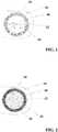
- the Figures 2 and 3is a further embodiment of the X-ray mark 20 can be seen.
- Backbone 10 and adhesive layer 40may be analogous to those in FIG FIG. 1 illustrated embodiment, in which case also alternative dimensions can be applied.
- the diameter of the recording 450 microns and the backbone 10have a web wall thickness of 100 microns.
- the hollow cylinder 22is made of tungsten here; but it can also be made of other suitable materials.
- a solid cylinder 24forms another marker element.
- the solid cylinder 24has a smaller diameter than the inner diameter of the hollow cylinder 22.
- the resulting gapis filled with an electrically non-conductive material forming a layer 42.
- a blank (solid cylinder) of pure gold (99%) having an outer diameter of 220 ⁇ m and a height of 130 ⁇ mis provided.
- the Rondeis immersed in a polymer solution of the silicone adhesive MED2-4213 (manufacturer Fa. NUSIL Technology) and then placed in the tungsten tube section. This is followed by curing in a tempering chamber at 150 ° C for 15 min.
- a tempering chamberat 150 ° C for 15 min.
- the backbone of Nitinol, the X-ray marker with a hollow cylinder made of tantalum and a plate made of platinumis a further variant for the previously described embodiment.
- the backbone of CoCr (L605), the X-ray marker with a hollow cylinder of tungsten and a round plate made of goldis a further variant for the previously described embodiment.
Landscapes
- Health & Medical Sciences (AREA)
- Life Sciences & Earth Sciences (AREA)
- Veterinary Medicine (AREA)
- Public Health (AREA)
- General Health & Medical Sciences (AREA)
- Animal Behavior & Ethology (AREA)
- Oral & Maxillofacial Surgery (AREA)
- Heart & Thoracic Surgery (AREA)
- Chemical & Material Sciences (AREA)
- Epidemiology (AREA)
- Surgery (AREA)
- Engineering & Computer Science (AREA)
- Biomedical Technology (AREA)
- Transplantation (AREA)
- Vascular Medicine (AREA)
- Medicinal Chemistry (AREA)
- Dermatology (AREA)
- Inorganic Chemistry (AREA)
- Cardiology (AREA)
- Optics & Photonics (AREA)
- Physics & Mathematics (AREA)
- Nuclear Medicine, Radiotherapy & Molecular Imaging (AREA)
- Pathology (AREA)
- Medical Informatics (AREA)
- Molecular Biology (AREA)
- Media Introduction/Drainage Providing Device (AREA)
Description
Translated fromGermanDie vorliegende Erfindung betrifft einen Röntgenmarker für eine Endoprothese. Ferner betrifft die Erfindung eine Endoprothese mit einem metallischen Grundkörper und mit einem an dem Grundkörper befestigten Röntgenmarker.The present invention relates to an x-ray marker for an endoprosthesis. Furthermore, the invention relates to an endoprosthesis with a metallic base body and with an attached to the body X-ray marker.
Stents sind endovaskuläre Prothesen, die zur Behandlung von Stenosen (Gefäßverengungen) eingesetzt werden können. Sie weisen einen Grundkörper in Form eines hohlzylinder- oder röhrenförmigen Grundgitters auf, das an beiden Längsenden der Röhren offen ist. Das röhrenförmige Grundgitter einer derartigen Endoprothese wird in das zu behandelnde Gefäß eingesetzt und dient dazu, das Gefäß zu stützen.Stents are endovascular prostheses that can be used to treat stenoses (vasoconstriction). They have a base body in the form of a hollow cylindrical or tubular base grid, which is open at both longitudinal ends of the tubes. The tubular base grid of such an endoprosthesis is inserted into the vessel to be treated and serves to support the vessel.
Derartige Stents oder andere Endoprothesen weisen häufig einen Grundkörper aus einem metallischen Werkstoff auf. Für die vorliegende Erfindung von besonderer Bedeutung sind biodegradierbare metallische Werkstoffe. Unter Biodegradation werden dabei hydrolytische, enzymatische und andere stoffwechselbedingte Abbauprozesse im lebenden Organismus verstanden, die vor allem durch die mit der Endoprothese in Kontakt gelangenden Körperflüssigkeiten verursacht werden und zu einer allmählichen Auflösung zumindest großer Teile der Endoprothese führen. Synonym zu dem Begriff Biodegradation wird häufig der Begriff Biokorrosion verwendet. Der Begriff Bioresorption umfasst die anschließende Resorption der Abbauprodukte durch den lebenden Organismus. Für den Grundkörper biodegradierbarer Endoprothesen geeignete Werkstoffe umfassen beispielsweise Legierungen von Magnesium, Eisen, Zink und Wolfram.
Zur postoperativen Überwachung des Heilungsfortschrittes oder zur Kontrolle minimalinvasiver Eingriffe ist die Röntgendiagnostik ein wichtiges Instrumentarium. So werden beispielsweise seit einigen Jahren Stents in den Koronararterien bei der akuten Myokardinfarkttherapie platziert. Nach gängigen Verfahren wird ein Katheter, der den Stent in einem nicht expandierten Zustand trägt, im Bereich der Läsion der koronaren Gefäßwand positioniert. Anschließend weitet sich der Stent entweder durch selbstexpansive Kräfte oder durch Inflation eines Ballons auf, um im expandierten Zustand eine Obstruktion der Gefäßwand zu verhindern. Der Vorgang der Positionierung und Expansion der Stents muss während der Prozedur durch den Kardiologen laufend überwacht werden.Such stents or other endoprostheses often have a base made of a metallic material. Of particular importance for the present invention are biodegradable metallic materials. Biodegradation is understood as meaning hydrolytic, enzymatic and other metabolism-related degradation processes in the living organism, which are primarily caused by the body fluids which come into contact with the endoprosthesis and lead to a gradual dissolution of at least large parts of the endoprosthesis. Synonymous with the term biodegradation, the term biocorrosion is often used. The term bioresorption covers the subsequent absorption of the degradation products by the living organism. Suitable materials for the body of biodegradable endoprostheses include, for example, alloys of magnesium, iron, zinc and tungsten.
For postoperative monitoring of the healing progress or for the control of minimally invasive procedures, X-ray diagnostics is an important tool. So For example, stents have been placed in the coronary arteries for acute myocardial infarction therapy for several years. Common practice is to position a catheter carrying the stent in an unexpanded state within the area of the lesion of the coronary vessel wall. Subsequently, the stent expands either by self-expanding forces or by inflation of a balloon to prevent in the expanded state obstruction of the vessel wall. The process of positioning and expanding the stents must be monitored continuously during the procedure by the cardiologist.
Im medizinischen Bereich wird mit Röntgenstrahlen im Energiebereich von 60 bis 120 keV, bei Anwendung am Herz typischerweise im Bereich von 80 bis 100 keV gearbeitet. Da der Röntgenabsorptionskoeffizient stark von der Energie abhängt, ist dieser Arbeitsbereich bei der Auswahl von geeigneten Markermaterialien zu berücksichtigen. Die Absorption (Intensitätsabschwächung) der Röntgenstrahlen kann vereinfacht mit einem exponentiellen Abschwächungsgesetz beschreiben werden.
Dabei ist I die gemessene Intensität nach dem Probendurchgang, I0 die Intensität der Strahlung vor dem Probendurchgang, µ / ρ der Massenabsorptionskoeffizient und x die Massendicke der Probe. Für Legierungen berechnet sich der Massenabsorptionskoeffizient durch Aufsummieren der Komponenten.In this case, I is the measured intensity after the sample passage, I0 is the intensity of the radiation before the sample passage, μ / ρ is the mass absorption coefficient and x is the mass thickness of the sample. For alloys, the mass absorption coefficient is calculated by summing up the components.
Bei geringer Absorption des gewählten Werkstoffs in einem gegebenen Energiebereich der Röntgenabsorption könnte demnach durch Erhöhung der Materialdicke eine Verbesserung der Röntgensichtbarkeit erreicht werden; jedoch stößt diese Maßnahme schnell an ihre Grenzen, insbesondere, wenn es um die Markierung filigraner Strukturen, wie sie bei Stents vorliegen, geht.Thus, with little absorption of the chosen material in a given energy range of X-ray absorption, increasing the material thickness could improve the radiopacity; However, this measure quickly reaches its limits, especially when it comes to marking filigree structures, such as those present in stents.
Es ist somit bekannt, Implantate mit einem Marker in Form einer Beschichtung, eines Bandes, eines Inlays oder andersartig angeformten Design zur Verbesserung der Röntgensichtbarkeit auszustatten. Beispielsweise werden Metallbänder aus Gold oder anderen Edelmetallen in bestimmten Bereichen eines Stents angebracht. Beispiele für derartige Röntgenmarker sind
Bei Implantaten aus biokorrodierbaren metallischen Werkstoffen - zum Beispiel auf der Basis von Magnesium, Eisen, Zink oder Wolfram - bestehen weitere Anforderungen an das Markermaterial:
- der Marker sollte durch die korrosiven Prozesse nicht frühzeitig vom Grundkörper des Implantates getrennt werden, um einer Fragmentbildung und damit der Gefahr der Embolisation vorzubeugen;
- der Marker sollte schon bei geringen Materialdicken eine hinreichende Röntgendichte besitzen; und
- das Markermaterial sollte möglichst keinen oder allenfalls einen geringen Einfluss auf die Degradation des Grundkörpers haben.
- the marker should not be separated early from the body of the implant by the corrosive processes in order to prevent fragmentation and thus the risk of embolization;
- The marker should have a sufficient radiopacity even with small material thicknesses; and
- The marker material should have as little or at most a slight influence on the degradation of the body.
Bei Stents, deren Grundkörper aus einem metallischen Material besteht, ergibt sich bei der Anordnung von Röntgenmarkern, beispielsweise bei radioopaken Elementen aus Gold, an dem Stent-Grundkörper das Problem, dass an dem Kontaktbereich zwischen dem Material des Grundkörpers und dem Material des Funktionselements eine Kontaktkorrosion auftritt. Diese führt zur Zerstörung des Stents beziehungsweise zur Abtrennung des Röntgenmarkers von der Stentstruktur, so dass die Endoprothese nicht mehr in der Lage ist, ihre Funktion zu erfüllen, bzw. nicht mehr aufgefunden werden kann. Röntgenmarker aus Gold oder Platin können aufgrund ihrer sehr ausgeprägten Lokalelementwirkung bei Grundkörpern aus Magnesium nicht zur Anwendung kommen. Auch bei Röntgenmarkern aus verschiedenen metallischen Komponenten stellt sich das Problem der Lokalelementbildung.In the case of stents whose basic body consists of a metallic material, the problem arises in the arrangement of x-ray markers, for example in the case of radiopaque elements made of gold, on the stent basic body that contact corrosion occurs at the contact area between the material of the basic body and the material of the functional element occurs. This leads to the destruction of the stent or to the separation of the X-ray marker from the stent structure, so that the endoprosthesis is no longer able to fulfill its function, or can no longer be found. X-ray markers made of gold or platinum can not be used because of their very pronounced local element effect in magnesium parent bodies. Even with X-ray markers made of various metallic components, the problem of local element formation arises.
In der Druckschrift
In der Druckschrift
Die Druckschrift
Die Druckschrift
Ein oder mehrere Nachteile des Standes der Technik werden mit Hilfe der erfindungsgemäßen Röntgenmarker gelöst oder zumindest gemindert. Der Röntgenmarker umfasst dabei einen Hohlzylinder aus einem ersten radioopaken Metall und ein mit dem Hohlzylinder fest verbundenes Markerelement, das im Innern des Hohlzylinders angeordnet ist. In einer bevorzugten Ausführungsform besteht das Markerelement aus einem zweiten radioopaken Metall oder einer Legierung daraus. Die für den Hohlzylinder und das weitere Markerelement verwendeten Metalle unterscheiden sich somit. Durch die Verwendung von unterschiedlichen Metallen können Lokalelemente bereits durch geschickte Materialwahl stark reduziert werden. Wird zum Beispiel das Hohlzylindermaterial dem Endoprothesenmaterial chemisch ähnlich gewählt, können Lokalelementeffekte bei metallischem Kontakt zum Körper der Endoprothese minimiert werden. Die Endoprothese ist allerdings ferner dadurch gekennzeichnet, dass sich zwischen dem Markerelement und dem Hohlzylinder ein elektrisch nicht leitfähiges Material befindet. Auf diese Weise lassen sich unerwünschte elektrochemische Prozesse zwischen den Metallen des Hohlzylinders und des Markerelements wirksam verhindern.One or more disadvantages of the prior art are solved or at least mitigated with the aid of the X-ray markers according to the invention. The x-ray marker comprises a hollow cylinder of a first radiopaque metal and a marker element fixedly connected to the hollow cylinder, which is arranged in the interior of the hollow cylinder. In a preferred embodiment, the marker element consists of a second radiopaque metal or an alloy thereof. The metals used for the hollow cylinder and the further marker element thus differ. By using different metals local elements can already be greatly reduced by skillful choice of materials. For example, if the hollow cylinder material is chemically similar to the endoprosthesis material, local element effects can be minimized by metallic contact with the body of the endoprosthesis. However, the endoprosthesis is further characterized in that there is an electrically non-conductive material between the marker element and the hollow cylinder. In this way, unwanted electrochemical processes between the metals of the hollow cylinder and the marker element can be effectively prevented.
Die erfindungsgemäßen Röntgenmarker können somit mit verschiedenen Dimensionen vorgefertigt werden, auf Lager gelegt und bei Bedarf in verschiedene Endoprothesen eingebracht werden, sowie auch auf verschiedene Patientengrößen angepasst werden, da allein aufgrund unterschiedlicher Körpermassen und damit verbundener Eindringtiefen mehr oder weniger Röntgenstrahlung absorbiert wird. Während der Lagerung sind korrosive Prozesse zwischen den verschiedenen metallischen Komponenten des Markers durch die Trennung mittels des nicht leitfähigen Materials unterbunden, selbst wenn Feuchtigkeit eintritt. Auch in-vivo wird ein solches korrosives Verhalten wirkungsvoll verhindert. Des Weiteren bietet der hierin vorgeschlagene Röntgenmarker die Möglichkeit die Röntgensichtbarkeit nicht nur an Patienten, sondern auch an den zukünftigen Gerätestandard der Röntgengeräte anzupassen und somit auch in Zukunft maßgeschneiderte Röntgenmarker zur Verfügung zu stellen, sowohl durch Materialwahl als auch durch effektive Materialdichte. Auch ist es von Vorteil, dass ansonsten notwendige und kostenintensive Vergoldungsprozesse wegfallen, die häufig auch bei nicht resorbierbaren Metallen durchgeführt werden müssen.The X-ray markers according to the invention can thus be prefabricated with various dimensions, placed in storage and introduced into different endoprostheses as needed, as well as adapted to different patient sizes, since more or less X-radiation is absorbed solely on account of different body masses and associated penetration depths. During storage, corrosive processes between the various metallic components of the marker are prevented by the separation by means of the non-conductive material, even when moisture enters. Even in vivo such corrosive behavior is effectively prevented. Furthermore, the X-ray marker proposed herein offers the possibility of adapting the radiopacity not only to patients but also to the future device standard of the X-ray devices and therefore also in the future tailor-made X-ray markers, both through material selection and through effective material density. It is also advantageous that otherwise necessary and costly gold plating processes are eliminated, which often have to be performed even with non-absorbable metals.
Ein Hohlzylinder im Sinne der vorliegenden Erfindung ist nicht auf eine klassische Form eines geraden Rohres mit einer kreisrunden Grundfläche beschränkt. Ein Hohlzylinder kann jedwede Grundfläche einnehmen, einschließlich kreisrunder, ellipsenförmiger, ellipsoider, dreieckiger, quadratischer, rechteckiger, vieleckiger, achtförmiger oder auch vollkommen ungeordneter Formen sofern mindestens eine Fläche durch die umgebenen Wände eingeschlossen wird. Es ist ebenfalls denkbar, dass die zwei sich gegenüber liegenden Seiten, die den Hohlraum beschreiben eine unterschiedliche Form aufweisen. Ebenfalls ist es denkbar, dass die Verbindung zwischen den Grundflächen, die den Hohlraum definiert, nicht rechtwinkelig auf den Grundflächen ansetzt und dass die sich gegenüberliegenden Grundflächen nicht parallel zu einander liegen. Ein Hohlzylinder beschreibt vielmehr einen oder mehrere durchgängige Volumina, die vorzugsweise schlauchförmig ausgestaltet sind.A hollow cylinder according to the present invention is not limited to a classic shape of a straight pipe with a circular base. A hollow cylinder may take any footprint, including circular, ellipsoidal, ellipsoidal, triangular, square, rectangular, polygonal, octahedral, or even disordered shapes if at least one surface is enclosed by the surrounding walls. It is also conceivable that the two opposite sides which describe the cavity have a different shape. It is also conceivable that the connection between the base surfaces, which defines the cavity, does not attach at right angles to the base surfaces and that the opposing base surfaces are not parallel to each other. A hollow cylinder rather describes one or more continuous volumes, which are preferably designed tubular.
Ein Markerelement im Sinne der vorliegenden Erfindung kann jede erdenkliche Form annehmen mit der Maßgabe, dass das Markerelement in das Volumen des Hohlzylinders eingefügt werden kann. Dabei können so ungeordnete Formen wie Pulverpartikel angenommen werden wie auch Vollzylinder, die passgenau in den Hohlzylinder eingepasst werden können, wie auch kugelförmige Partikel.A marker element according to the present invention may take any conceivable form with the proviso that the marker element can be inserted into the volume of the hollow cylinder. In this case, it is possible to assume such disordered forms as powder particles as well as solid cylinders, which can be fitted precisely into the hollow cylinder, as well as spherical particles.
Gemäß einer bevorzugten Variante liegt das Markerelement als Metallpulver oder in Form von Metallpartikeln vor. Das Metallpulver beziehungsweise die Metallpartikel sind dabei in das elektrisch nicht leitfähige Material eingebettet. Zur Herstellung des Röntgenmarkers kann demnach einfach ein Komposit aus Metallpulver beziehungsweise -partikel und elektrisch nicht leitfähigem Material in das Innere des Hohlzylinders eingebracht werden. Ein Gewichtsanteil des Metalls am Komposit sollte vorzugsweise im Bereich von 45 bis 97%, bevorzugt 60 bis 93% liegen. Das Markerelement ist dabei in dem Komposit so eingebettet, dass es zu keinem Metall-Metall-Kontakt zwischen Markerelement und Hohlzylinder kommt. Dies ist gut zu erreichen, wenn der Gewichtsanteil des Metalls am Komposit 97% nicht überschreitet und das Komposit vor dem Einsetzen in den Zylinder stark durchmischt wurde. Durch die starke Durchmischung wird gewährleistet, dass die Metallpulverkörner oder Metallpartikel vom elektrisch nicht leitfähigen Material umschlossen werden. Durch die gute Durchmischung und die elektrische Isolation der Metallpulverkörner oder Metallpartikel kann das Markerelement verfahrenstechnisch günstig auch ohne weitere Schritte in den Hohlzylinder eingefüllt werden, wenn die Konsistenz des Komposits dies gut zulässt. Eine elektrische Isolation zwischen Hohlzylinder und Markerelement kann bevorzugt auch dadurch erreicht werden, dass das nicht leitende Material entweder vor Einsetzen des Markerelements auf die Außenseite des Markerelements oder auf die Innenseite des Hohlzylinders aufgetragen wird.According to a preferred variant, the marker element is present as metal powder or in the form of metal particles. The metal powder or the metal particles are embedded in the electrically non-conductive material. Accordingly, a composite of metal powder or particles and electrically nonconductive material can simply be introduced into the interior of the hollow cylinder to produce the x-ray marker. A weight proportion of the metal in the composite should preferably be in the range of 45 to 97%, preferably 60 to 93%. The marker element is embedded in the composite so that there is no metal-to-metal contact between marker element and Hollow cylinder comes. This is easy to achieve if the weight percentage of the metal on the composite does not exceed 97% and the composite has been thoroughly mixed before insertion into the cylinder. The strong mixing ensures that the metal powder grains or metal particles are enclosed by the electrically non-conductive material. Due to the good mixing and the electrical insulation of the metal powder grains or metal particles, the marker element can advantageously be filled into the hollow cylinder without further steps, provided the consistency of the composite permits this. An electrical insulation between the hollow cylinder and the marker element can preferably also be achieved by applying the non-conductive material to the outside of the marker element or to the inside of the hollow cylinder either before inserting the marker element.
Gemäß einer weiteren bevorzugten Variante ist das Markerelement ein Vollzylinder mit einem geringeren Durchmesser als der Innendurchmesser des Hohlzylinders. Das elektrisch nicht leitfähige Material bildet dabei eine Schicht zwischen einer inneren Mantelfläche des Hohlzylinders und einer Mantelfläche des Vollzylinders. Der Vollzylinder gewährt eine hinreichend hohe Röntgensichtbarkeit. Die umlaufende Schicht weist insbesondere eine Schichtdicke im Bereich von 7,5 - 15 µm auf. In diesem Schichtdickenbereich wird bevorzugt eine effektive elektrische Isolation, sowie eine gute Haftung des Vollzylinders an den Hohlzylinder erreicht ohne die Ausmaße des Röntgenmarkers unnötig zu vergrößern.According to a further preferred variant, the marker element is a solid cylinder with a smaller diameter than the inner diameter of the hollow cylinder. The electrically non-conductive material forms a layer between an inner circumferential surface of the hollow cylinder and a lateral surface of the solid cylinder. The solid cylinder provides a sufficiently high radiopacity. In particular, the circumferential layer has a layer thickness in the range of 7.5-15 μm. In this layer thickness range, effective electrical insulation and good adhesion of the solid cylinder to the hollow cylinder are preferably achieved without unnecessarily increasing the dimensions of the x-ray marker.
Zur Verbesserung der Haftung weist die innere Mantelfläche des Hohlzylinders und die Mantelfläche des Vollzylinders vorzugsweise einen Rauheitswert Ra im Bereich von 0,4 - 2 µm, weiter bevorzugt von 0,6 bis 1,2 µm auf. Eine gute Anhaftung kann dazu beitragen, dass selbst bei geringer Wanddicke die Kräfte, die den Röntgenmarker bei mechanischer Belastung aus dem Verbund mit der Endoprothese heraus lösen würden, hoch sind und somit eine hohe Verbundfestigkeit generiert wird. Die Wahrscheinlichkeit für den ungewollten Verlust des Markers wird dadurch deutlich herabgesetzt.To improve the adhesion, the inner circumferential surface of the hollow cylinder and the lateral surface of the solid cylinder preferably has a roughness Ra in the range of 0.4 to 2 microns, more preferably from 0.6 to 1.2 microns. Good adhesion can contribute to the fact that, even with a small wall thickness, the forces that would release the X-ray marker from the composite with the endoprosthesis under mechanical stress are high and thus a high bond strength is generated. The probability of the unwanted loss of the marker is thereby significantly reduced.
Ferner ist bevorzugt, wenn der Hohlzylinder aus Wolfram, Tantal oder Legierungen dieser Metalle besteht. Weiterhin kann der Hohlzylinder einen Durchmesser im Bereich von 100 - 500 µm und eine Höhe im Bereich von 50 - 180 µm aufweisen. Bevorzugt ist zudem, wenn der Hohlzylinder eine Wanddicke im Bereich von 10 - 50 µm aufweist. Mit diesen Ausmaßen und Materialien kann eine ausreichend gute Röntgensichtbarkeit erreicht werden, ohne unnötigen Materialaufwand in Kauf nehmen zu müssen.Furthermore, it is preferred if the hollow cylinder consists of tungsten, tantalum or alloys of these metals. Furthermore, the hollow cylinder can have a diameter in the range of 100 - 500 microns and a height in the range of 50 - have 180 microns. In addition, it is preferred if the hollow cylinder has a wall thickness in the range of 10 to 50 μm. With these dimensions and materials, a sufficiently good radiopacity can be achieved without having to put up with unnecessary material expenditure.
Das elektrisch nicht leitfähige Material ist vorzugsweise ein polymerer Klebstoff. Geeignete polymere Klebstoffe umfassen vorzugsweise Polyurethane, Silikone, Polymethylmethacrylate, Cyanoacrylate, Polyester und Epoxidharze.The electrically non-conductive material is preferably a polymeric adhesive. Suitable polymeric adhesives preferably include polyurethanes, silicones, polymethyl methacrylates, cyanoacrylates, polyesters, and epoxy resins.
In einer bevorzugten Ausführungsform werden elastische polymere Klebstoffe verwendet. Geeignete elastische Klebstoffe umfassen Silikone, Polylactide, Polyhydroxybuttersäure sowie deren Blends. Elastische Klebstoffe haben den Vorteil, dass sie zu einer verbesserten Trackability, also zur Anpassung an das umgebende Gewebe während des Vordringens der Endoprothese beim Einsetzen, beitragen. Ein vorzeitiger Verlust eines Röntgenmarkers wird dadurch nochmals unwahrscheinlicher.In a preferred embodiment, elastic polymeric adhesives are used. Suitable elastic adhesives include silicones, polylactides, polyhydroxybutyric acid and blends thereof. Elastic adhesives have the advantage that they contribute to improved trackability, ie adaptation to the surrounding tissue during the penetration of the endoprosthesis during insertion. A premature loss of an X-ray marker is thus even more unlikely.
Das Markerelement, insbesondere in der Ausführungsform eines Vollzylinders kann insbesondere aus Gold, Platin, Iridium oder Legierungen daraus bestehen, also Metallen, die besonders gute radioopake Eigenschaften besitzen, jedoch auch kostenintensiv sind. Wenn der Hohlzylinder aus Tantal oder seinen Legierungen geformt ist, besteht das Markerelement vorzugsweise aus Wolfram. Durch die kompakte Bauweise unter gleichzeitiger Isolation zur Verhinderung von Lokalelementen kann hier kostenschonend ein Röntgenmarker aufgebaut werden.The marker element, in particular in the embodiment of a solid cylinder, may consist in particular of gold, platinum, iridium or alloys thereof, ie metals which have particularly good radiopaque properties but are also cost-intensive. When the hollow cylinder is formed of tantalum or its alloys, the marker element is preferably tungsten. Due to the compact design with simultaneous isolation to prevent local elements can be constructed cost-saving an X-ray marker.
In einer bevorzugten Ausführungsform kann durch geeignete Wahl der Materialien für Hohlzylinder und Markerelement in vorteilhafter Weise ein besonders breiter Energiebereich von Röntgenstrahlen absorbiert werden. In einer bevorzugten Ausführungsform ist der Hohlzylinder aus Tantal oder Legierungen daraus gefertigt und das Markerelement aus Gold oder Platin hergestellt. In einer weiteren bevorzugten Ausführungsform sind der Hohlzylinder aus Wolfram und das Markerelement aus Gold gefertigt. Insbesondere ist bevorzugt, wenn der Hohlzylinder aus Tantal und das Markerelement aus Gold gefertigt ist.In a preferred embodiment, a particularly wide energy range of X-rays can be absorbed by suitable choice of materials for hollow cylinder and marker element in an advantageous manner. In a preferred embodiment, the hollow cylinder is made of tantalum or alloys thereof and the marker element made of gold or platinum. In a further preferred embodiment, the hollow cylinder made of tungsten and the marker element are made of gold. In particular, it is preferred if the hollow cylinder is made of tantalum and the marker element is made of gold.
Ein weiterer Aspekt der Erfindung liegt in der Bereitstellung einer Endoprothese mit einem metallischen Grundkörper und mit mindestens einem an dem Grundkörper befestigten erfindungsgemäßen Röntgenmarker. Vorzugsweise besteht der Grundkörper aus einem biodegradierbaren, metallischen Werkstoff, insbesondere einer Magnesiumlegierung. Zwischen dem Röntgenmarker und dem Grundkörper befindet sich vorzugsweise ein elektrisch nicht leitfähiges Material, insbesondere ein polymerer Klebstoff, der korrosive Prozesse zwischen den beiden metallischen Werkstoffen verhindert. Ein Montageprozess kann durch Einkleben vorgefertigter Marker in vorgegebene Aufnahmen an der Endoprothese vereinfacht werden.Another aspect of the invention is the provision of an endoprosthesis with a metallic base body and with at least one X-ray marker according to the invention attached to the base body. Preferably, the base body consists of a biodegradable, metallic material, in particular a magnesium alloy. Between the X-ray marker and the base body is preferably an electrically non-conductive material, in particular a polymeric adhesive, which prevents corrosive processes between the two metallic materials. An assembly process can be simplified by pasting in prefabricated markers in predetermined recordings on the endoprosthesis.
In einer bevorzugten Ausführungsform kann das elektrisch nicht leitfähige Material in Form einer Schicht zwischen Hohlzylinder und Endoprothese ausgebildet sein. In einer weiter bevorzugten Ausführungsform hat die Schicht aus elektrisch nicht leitfähigem Material eine Dicke von über 5 µm und bevorzugt eine Dicke von 7,5 - 15 µm.In a preferred embodiment, the electrically non-conductive material may be formed in the form of a layer between the hollow cylinder and endoprosthesis. In a further preferred embodiment, the layer of electrically nonconductive material has a thickness of more than 5 μm and preferably a thickness of 7.5-15 μm.
Es hat sich vorteilhafter Weise gezeigt, dass durch Einbringung von zwei isolierenden Schichten, wobei die eine zwischen Markerelement und Hohlzylinder und die zweite zwischen Hohlzylinder und Endoprothese angeordnet ist, eine vollständige oder annähernd vollständige Unterbindung der Entstehung von galvanischen Elementen und damit verbundenen Stromflüssen durch Lokalelementbildung erreicht werden kann. Eine solche Endoprothese weist dadurch eine wesentlich verbesserte Lebensdauer und Verträglichkeit auf, sowie ein vermindertes Risiko vorzeitig einen Röntgenmarker unkontrolliert zu verlieren. Ferner können diese Marker in Endoprothesen unterschiedlichster Materialien eingesetzt werden, ohne dass die Gefahr besteht, dass es zu negativen Interaktionen zwischen den verwendeten Materialien kommt.It has been found to be advantageous that by introducing two insulating layers, one being arranged between the marker element and the hollow cylinder and the second between the hollow cylinder and the endoprosthesis, a complete or almost complete elimination of the formation of galvanic elements and associated current flows by local element formation is achieved can be. Such an endoprosthesis thus has a significantly improved durability and compatibility, as well as a reduced risk of prematurely losing an X-ray marker uncontrolled. Furthermore, these markers can be used in endoprostheses of a wide variety of materials without the risk of negative interactions between the materials used.
In einer weiteren Ausführungsform wird eine Endoprothese mit einem metallischen Grundkörper und mit mindestens einem an dem Grundkörper befestigten erfindungsgemäßen Röntgenmarker vorgeschlagen, wobei der metallische Grundkörper zumindest am proximalen und distalen Ende einen Mehrfachmarker, insbesondere einen Doppelmarker aufweist. Ein Mehrfachmarker, insbesondere ein Doppelmarker, umfasst hierbei mindestens zwei benachbarte unterschiedliche erfindungsgemäße Röntgenmarker, im Falle eines Doppelmarkers zwei unterschiedliche erfindungsgemäße Röntgenmarker. Die unterschiedlichen erfindungsgemäßen Röntgenmarker unterscheiden sich hierbei durch die Wahl der Materialien für den Hohlzylinder und das Markerelement, insbesondere aber durch die Wahl für das Material des Markerelements. Somit wird eine Endoprothese vorgeschlagen, mit einem metallischen Grundkörper und mit mindestens einem an dem Grundkörper befestigten erfindungsgemäßen Röntgenmarker, wobei der metallische Grundkörper zumindest am proximalen und distalen Ende einen Mehrfachmarker aufweist, wobei der Mehrfachmarker mindestens zwei benachbarte unterschiedliche erfindungsgemäße Röntgenmarker umfasst, und vorzugsweise wobei die mindestens zwei benachbarten unterschiedlichen erfindungsgemäßen Röntgenmarker unterschiedliche Markerelemente aufweisen.In a further embodiment, an endoprosthesis with a metallic base body and with at least one X-ray marker attached to the base body according to the invention is proposed, wherein the metallic base body has a multiple marker, in particular a double marker, at least at the proximal and distal ends. A multiple marker, in particular a double marker, comprises in this case, at least two adjacent different X-ray markers according to the invention, in the case of a double marker, two different X-ray markers according to the invention. The different X-ray markers according to the invention differ here by the choice of materials for the hollow cylinder and the marker element, but in particular by the choice of the material of the marker element. Thus, an endoprosthesis is proposed, with a metallic base body and with at least one attached to the base body X-ray marker according to the invention, the metallic base body having at least at the proximal and distal ends of a multiple marker, the multiple marker comprises at least two adjacent different X-ray marker according to the invention, and preferably wherein the at least two adjacent different x-ray markers according to the invention have different marker elements.
In einer beispielshaften Ausführungsform umfasst eine solche hier vorgeschlagene Endoprothese je einen Doppelmarker sowohl am distalen als auch am proximalen Ende, wobei die Hohlzylinder eines Doppelmarkers aus Tantal gefertigt sind, während die Markerelemente aus Wolfram und aus Platin oder in einer alternativen Ausführungsform aus Gold und Platin gefertigt sind.In an exemplary embodiment, such an endoprosthesis as proposed herein each includes a double marker at both the distal and proximal ends, wherein the hollow cylinders of a dual marker are made of tantalum, while the marker elements are made of tungsten and platinum or, in an alternative embodiment, gold and platinum are.
Eine solche Ausführungsform einer Endoprothese, umfassend Mehrfachmarker wie hierin beschrieben hat den Vorteil, dass gewährleistet ist, dass mit unterschiedlichen Röntgengeräten eine optimale Röntgensichtbarkeit generiert werden kann. So führt beispielsweise die Gerätespezifik (mit einem bestimmten Beschleunigungsspannungsbereich xxx) des Röntgengerätes yyy zu einer besseren Sichtbarkeit des Wolframmarkers. Ein anderes Röntgengerät zzz (mit anderem Beschleunigungsspannungsbereich aaa) stellt die Marker aus Gold und/ oder Platin besser dar. Damit wird eine Geräteunabhängigkeit für die Röntgensichtbarkeit hergestellt.Such an embodiment of an endoprosthesis comprising multiple markers as described herein has the advantage that it is ensured that optimal X-ray visibility can be generated with different X-ray devices. For example, the device specificity (with a certain acceleration voltage range xxx) of the x-ray device yyy leads to better visibility of the tungsten marker. Another xzz device zzz (with different acceleration voltage range aaa) displays the markers made of gold and / or platinum better. This ensures device independence for the radiopacity.
Somit kann gemäß dem vorliegenden Vorschlag eine Endoprothese bereitgestellt werden, die einen hierin vorgeschlagenen Schutz vor Lokalelementen aufweist, und darüber hinaus durch eine optimale Röntgensichtbarkeit ausgezeichnet ist.Thus, in accordance with the present proposal, an endoprosthesis may be provided which has local element protection as suggested herein and which is further distinguished by optimal radiopacity.
Weitere bevorzugte Ausgestaltungen der Erfindung ergeben sich aus der nachfolgenden Beschreibung.Further preferred embodiments of the invention will become apparent from the following description.
Die Erfindung wird nachfolgend anhand von in Figuren dargestellten Ausführungsbeispielen näher erläutert. Es zeigen:
- Fig. 1
- Eine schematische Draufsicht auf einen Röntgenmarker gemäß einer ersten erfindungsgemäßen Ausführungsform, der in einer komplementären Aufnahme einer Endoprothese sitzt.
- Fig. 2
- Eine schematische Draufsicht auf einen Röntgenmarker gemäß einer zweiten erfindungsgemäßen Ausführungsform, der in einer komplementären Aufnahme einer Endoprothese sitzt.
- Fig. 3
- Schnittansicht durch den in
Figur 2 dargestellten Röntgenmarker.
- Fig. 1
- A schematic plan view of an X-ray marker according to a first embodiment of the invention, which sits in a complementary receptacle of an endoprosthesis.
- Fig. 2
- A schematic plan view of an X-ray marker according to a second embodiment of the invention, which sits in a complementary receptacle of an endoprosthesis.
- Fig. 3
- Section through the in
FIG. 2 illustrated x-ray markers.
Der Röntgenmarker 20 kann wie folgt hergestellt werden:
- Ein Rohrabschnitt aus 99%-igem Reintantal wird auf eine geeignete Länge geschnitten, beispielsweise von 150 µm. Ein Außendurchmesser b des Rohrabschnitts b kann beispielsweise 310 µm betragen, die Wandstärke c des Rohrs kann ferner beispielsweise 50 µm betragen. Der resultierende Innendurchmesser in dem hier beschriebenen Beispiel liegt somit bei 210 µm. Die Innen- und Außenoberflächen sind sandgestrahlt, anschließend thermisch oxidiert und weisen einen geeigneten Rauheitswert von beispielsweise Ra = 0,8 µm auf.
- A tube section of 99% pure tantalum is cut to a suitable length, for example of 150 μm. An outer diameter b of the pipe section b may be, for example 310 microns, the wall thickness c of the tube may also be for example 50 microns. The resulting inner diameter in the example described here is thus 210 μm. The inner and outer surfaces are sandblasted, then thermally oxidized and have a suitable roughness value of, for example, Ra = 0.8 μm.
Es folgt die Herstellung eines Metallpulver/Polymercompounds mit folgenden Inhaltsstoffen im Verhältnis von 92 Gew.% Metallpulver und 8 Gew.% Polymer:
- Metallpulver: Au, mittlere Partikelgröße 15 nm
- Polymer: Silikonklebstoff MED2-4213 (Hersteller Fa. NUSIL Technology)
- Metal powder: Au, average particle size 15 nm
- Polymer: silicone adhesive MED2-4213 (manufacturer: NUSIL Technology)
Nach dem Abwägen der Einzelkomponenten, folgt manuelles Verrühren und anschließendes Vermengen der Komponenten in Zentrifugen zur Herstellung einer homogenen Mischung. Die Mischung wird in Kartuschen verfüllt und über eine Kanüle ohne Einschlüsse von Luft in das Tantalrohr injiziert. Anschließend wird in einer Temperierkammer bei 150°C über 15 min ausgehärtet.After weighing the individual components, followed by manual stirring and subsequent mixing of the components in centrifuges to produce a homogeneous mixture. The mixture is filled into cartridges and injected into the tantalum tube via a cannula without air inclusions. It is then cured in a tempering chamber at 150 ° C for 15 min.
Mehrere dieser nunmehr gefüllten Rohrabschnitte mit dem ausgehärteten Inlay werden aufrecht in eine Schablone verbracht und beidseitig auf die Nennhöhe von 120 µm auf Schleifscheiben heruntergeschliffen.Several of these now filled tube sections with the hardened inlay are placed upright in a template and ground down on both sides to the nominal height of 120 μm on grinding wheels.
Den
Der Röntgenmarker 20 kann wie folgt hergestellt werden:
- Es wird ein Rohrabschnitt aus 99%-igem Reinwolfram auf eine Länge von 130 µm geschnitten. Ein Außendurchmesser des Rohrabschnitts beträgt 410 µm, die Wandstärke beträgt 80 µm. Der resultierende Innendurchmesser liegt bei 250 µm. Die Innen- und Außenoberflächen sind sandgestrahlt, anschließend thermisch oxidiert und weisen einen geeigneten Rauheitswert von beispielsweise Ra = 0,8 µm auf.
- It is cut a pipe section of 99% pure tungsten to a length of 130 microns. An outer diameter of the pipe section is 410 microns, the wall thickness is 80 microns. The resulting inner diameter is 250 microns. The inner and outer surfaces are sandblasted, then thermally oxidized and have a suitable roughness value of, for example, Ra = 0.8 μm.
Ferner wird eine Ronde (Vollzylinder) aus Reingold (99%) mit einem Außendurchmesser von 220 µm und einer Höhe von 130 µm bereitgestellt. Die Ronde wird in eine Polymerlösung des Silikonklebstoffs MED2-4213 (Hersteller Fa. NUSIL Technology) getaucht und anschließend in den Wolframrohrabschnitt verbracht. Es folgt Aushärten in einer Temperierkammer bei 150°C über 15 min. Mehrere dieser gefüllten Rohrabschnitte werden aufrecht in eine Schablone verbracht und beidseitig auf die Nennhöhe von 120 µm auf Schleifscheiben heruntergeschliffen.Further, a blank (solid cylinder) of pure gold (99%) having an outer diameter of 220 μm and a height of 130 μm is provided. The Ronde is immersed in a polymer solution of the silicone adhesive MED2-4213 (manufacturer Fa. NUSIL Technology) and then placed in the tungsten tube section. This is followed by curing in a tempering chamber at 150 ° C for 15 min. Several of these filled tube sections are placed upright in a template and ground down on both sides to the nominal height of 120 μm on grinding wheels.
Gemäß einer weiteren Variante für die vorab beschriebene Ausführungsform kann das Grundgerüst aus Nitinol, der Röntgenmarker mit einem Hohlzylinder aus Tantal und einer Ronde aus Platin bestehen. Alternativ kann das Grundgerüst aus CoCr (L605), der Röntgenmarker mit einem Hohlzylinder aus Wolfram und einer Ronde aus Gold bestehen.According to a further variant for the previously described embodiment, the backbone of Nitinol, the X-ray marker with a hollow cylinder made of tantalum and a plate made of platinum. Alternatively, the backbone of CoCr (L605), the X-ray marker with a hollow cylinder of tungsten and a round plate made of gold.
Claims (15)
- An x-ray marker (20) for an endoprosthesis, wherein the x-ray marker (20) comprises a hollow cylinder (22) made of a first radiopaque metal and a marker element, which is fixedly connected to the hollow cylinder (22) and which is arranged inside the hollow cylinder (22) and consists of a second radiopaque metal or an alloy thereof,
characterized in that
an electrically non-conductive material is located between the marker element and the hollow cylinder (22). - The x-ray marker as claimed in claim 1, wherein the marker element is present as metal powder or in the form of metal particles which is/are embedded in the electrically non-conductive material.
- The x-ray marker as claimed in claim 1, wherein the marker element is a solid cylinder (24) with a diameter smaller than the inner diameter of the hollow cylinder (22) and the electrically non-conductive material forms a layer (42) between an inner lateral surface of the hollow cylinder (22) and a lateral surface of the solid cylinder (24).
- The x-ray marker as claimed in claim 3, wherein the peripheral layer (42) has a layer thickness in the range of 7.5-15 µm.
- The x-ray marker as claimed in claim 3 or 4, wherein the inner lateral surface of the hollow cylinder (22) and the lateral surface of the solid cylinder (24) have a roughness Ra in the range of 0.4-2 µm.
- The x-ray marker as claimed in any one of the preceding claims, wherein the hollow cylinder (22) consists of tungsten, tantalum or alloys of these metals.
- The x-ray marker as claimed in any one of the preceding claims, wherein the hollow cylinder (22) has a diameter in the range of 100-500 µm and a height in the range of 50-180 µm.
- The x-ray marker as claimed in any one of the preceding claims, wherein the hollow cylinder (22) has a wall thickness in the range of 10-50 µm.
- The x-ray marker as claimed in any one of the preceding claims, wherein the electrically non-conductive material is a polymer adhesive.
- The x-ray marker as claimed in any one of the preceding claims, wherein the marker element consists of gold, platinum, iridium or alloys thereof.
- The x-ray marker as claimed in any one of claims 1 to 9, wherein the marker element consists of tungsten and the hollow cylinder (22) is formed from tantalum or alloys thereof.
- An endoprosthesis having a metallic main body (10) and having at least one x-ray marker (20) as claimed in any one of the preceding claims secured to the main body (10).
- The endoprosthesis as claimed in claim 12, wherein the main body (10) consists of a biodegradable, metallic material.
- The endoprosthesis as claimed in claim 12 or 13, wherein an electrically non-conductive material is located between the x-ray marker (20) and the main body (10).
- The endoprosthesis as claimed in any one of claims 12 to 14, wherein the metallic main body (10) has a multiple marker at least at a proximal and a distal end, wherein the multiple marker comprises at least two adjacent different x-ray markers (20).
Applications Claiming Priority (1)
| Application Number | Priority Date | Filing Date | Title |
|---|---|---|---|
| DE102015118859 | 2015-11-04 |
Publications (2)
| Publication Number | Publication Date |
|---|---|
| EP3165238A1 EP3165238A1 (en) | 2017-05-10 |
| EP3165238B1true EP3165238B1 (en) | 2018-02-14 |
Family
ID=56958736
Family Applications (1)
| Application Number | Title | Priority Date | Filing Date |
|---|---|---|---|
| EP16187958.0AActiveEP3165238B1 (en) | 2015-11-04 | 2016-09-09 | X-ray marker for an endoprosthesis |
Country Status (3)
| Country | Link |
|---|---|
| US (1) | US11000389B2 (en) |
| EP (1) | EP3165238B1 (en) |
| DE (1) | DE102016116919B4 (en) |
Families Citing this family (9)
| Publication number | Priority date | Publication date | Assignee | Title |
|---|---|---|---|---|
| ES2836190T3 (en)* | 2016-08-10 | 2021-06-24 | Cortronik GmbH | X-ray marker for absorbable metal framework with high X-ray visibility and built-in self-passivation effect |
| DE102016114894A1 (en) | 2016-08-11 | 2018-02-15 | Cortronik GmbH | X-ray marker for absorbable metallic scaffolds with high radiopacity and integrated self-passivation effect |
| EP4464369A3 (en) | 2017-11-06 | 2025-02-26 | Pacesetter, Inc. | Biostimulator having fixation element |
| EP3560452B1 (en) | 2018-04-24 | 2024-05-15 | Biotronik Ag | Marker element and method for its production |
| DE102018113810A1 (en) | 2018-06-11 | 2019-12-12 | Cortronik GmbH | Function marker element and method for its production |
| US11577086B2 (en) | 2018-08-20 | 2023-02-14 | Pacesetter, Inc. | Fixation mechanisms for a leadless cardiac biostimulator |
| USD894396S1 (en) | 2019-03-08 | 2020-08-25 | Pacesetter, Inc. | Leadless biostimulator attachment feature |
| US11541243B2 (en) | 2019-03-15 | 2023-01-03 | Pacesetter, Inc. | Biostimulator having coaxial fixation elements |
| EP3944819A1 (en) | 2020-07-30 | 2022-02-02 | Koninklijke Philips N.V. | X-ray position tracking |
Family Cites Families (12)
| Publication number | Priority date | Publication date | Assignee | Title |
|---|---|---|---|---|
| CA2188429C (en)* | 1994-05-09 | 2000-10-31 | David W. Mayer | Clad composite stent |
| US5741327A (en) | 1997-05-06 | 1998-04-21 | Global Therapeutics, Inc. | Surgical stent featuring radiopaque markers |
| US6174330B1 (en) | 1997-08-01 | 2001-01-16 | Schneider (Usa) Inc | Bioabsorbable marker having radiopaque constituents |
| US6355058B1 (en) | 1999-12-30 | 2002-03-12 | Advanced Cardiovascular Systems, Inc. | Stent with radiopaque coating consisting of particles in a binder |
| US20040267203A1 (en) | 2003-06-26 | 2004-12-30 | Potter Daniel J. | Splittable cannula having radiopaque marker |
| FR2867059B1 (en) | 2004-03-03 | 2006-05-26 | Braun Medical | ENDOPROTHESIS WITH MARKERS FOR CONDUCTING A LIVING BODY |
| DE102005039136B4 (en) | 2005-08-18 | 2011-07-28 | Admedes Schuessler GmbH, 75179 | Improving the radiopacity and corrosion resistance of NiTi stents using sandwiched rivets |
| US20070156230A1 (en) | 2006-01-04 | 2007-07-05 | Dugan Stephen R | Stents with radiopaque markers |
| DE102008043642A1 (en) | 2008-11-11 | 2010-05-12 | Biotronik Vi Patent Ag | endoprosthesis |
| EP2399619B1 (en)* | 2010-06-25 | 2015-08-05 | Biotronik AG | Implant and Method for Manufacturing Same |
| EP2457601B1 (en)* | 2010-11-08 | 2015-07-22 | Biotronik AG | Marker composite and medical implant comprising an x-ray marker |
| US9999527B2 (en)* | 2015-02-11 | 2018-06-19 | Abbott Cardiovascular Systems Inc. | Scaffolds having radiopaque markers |
- 2016
- 2016-09-09EPEP16187958.0Apatent/EP3165238B1/enactiveActive
- 2016-09-09DEDE102016116919.6Apatent/DE102016116919B4/ennot_activeExpired - Fee Related
- 2016-09-12USUS15/262,957patent/US11000389B2/enactiveActive
Non-Patent Citations (1)
| Title |
|---|
| None* |
Also Published As
| Publication number | Publication date |
|---|---|
| US11000389B2 (en) | 2021-05-11 |
| DE102016116919B4 (en) | 2018-05-17 |
| US20170119555A1 (en) | 2017-05-04 |
| DE102016116919A1 (en) | 2017-05-04 |
| EP3165238A1 (en) | 2017-05-10 |
Similar Documents
| Publication | Publication Date | Title |
|---|---|---|
| EP3165238B1 (en) | X-ray marker for an endoprosthesis | |
| EP2184038B1 (en) | Endoprosthesis | |
| EP2457601B1 (en) | Marker composite and medical implant comprising an x-ray marker | |
| EP1420701B1 (en) | Device for the implantation of occlusion means | |
| EP1124594B1 (en) | Implant with cavities containing therapeutic agents | |
| EP2438891A1 (en) | Stent having increased visibility in the X-ray image | |
| EP2399619B1 (en) | Implant and Method for Manufacturing Same | |
| WO2005070308A2 (en) | Device for implanting electrically isolated occlusion helixes | |
| EP3463206B1 (en) | Vasospasm treatment | |
| DE102006038232A1 (en) | Endoprosthesis and method for producing such | |
| DE102004044679A1 (en) | Implant with low radial strength | |
| EP1897567A1 (en) | X-ray marker for medical implants made of a bio-corrodible metal substance | |
| DE102005039136B4 (en) | Improving the radiopacity and corrosion resistance of NiTi stents using sandwiched rivets | |
| EP2630978B1 (en) | Implant and method for production thereof | |
| EP2258323B1 (en) | Implantation device for stents with a functionally structured surface | |
| EP2151256A2 (en) | Endoprosthesis and method for manufacturing the same | |
| EP4027910A1 (en) | Implant for treating aneurysms | |
| DE102011115238B4 (en) | A body implant with improved radiopacity, combination of a catheter, a guide wire, and a body implant and method for increasing the radiopacity of a body implant | |
| EP2656944B1 (en) | Method for producing an implant | |
| EP3560452B1 (en) | Marker element and method for its production | |
| EP3643337B1 (en) | Stent for implanting into a cavity of a human or animal body and method for producing an x-ray-opaque layer suspension on a stent | |
| WO2013135260A1 (en) | Body implant having a marker element | |
| EP2446863A1 (en) | Stent with radially asymmetric force distribution |
Legal Events
| Date | Code | Title | Description |
|---|---|---|---|
| PUAI | Public reference made under article 153(3) epc to a published international application that has entered the european phase | Free format text:ORIGINAL CODE: 0009012 | |
| AK | Designated contracting states | Kind code of ref document:A1 Designated state(s):AL AT BE BG CH CY CZ DE DK EE ES FI FR GB GR HR HU IE IS IT LI LT LU LV MC MK MT NL NO PL PT RO RS SE SI SK SM TR | |
| AX | Request for extension of the european patent | Extension state:BA ME | |
| 17P | Request for examination filed | Effective date:20170711 | |
| RBV | Designated contracting states (corrected) | Designated state(s):AL AT BE BG CH CY CZ DE DK EE ES FI FR GB GR HR HU IE IS IT LI LT LU LV MC MK MT NL NO PL PT RO RS SE SI SK SM TR | |
| GRAP | Despatch of communication of intention to grant a patent | Free format text:ORIGINAL CODE: EPIDOSNIGR1 | |
| RIC1 | Information provided on ipc code assigned before grant | Ipc:A61L 31/02 20060101ALI20170815BHEP Ipc:A61B 90/00 20160101ALI20170815BHEP Ipc:A61L 27/04 20060101AFI20170815BHEP Ipc:A61L 31/18 20060101ALI20170815BHEP Ipc:A61L 27/50 20060101ALI20170815BHEP | |
| INTG | Intention to grant announced | Effective date:20170915 | |
| GRAS | Grant fee paid | Free format text:ORIGINAL CODE: EPIDOSNIGR3 | |
| GRAA | (expected) grant | Free format text:ORIGINAL CODE: 0009210 | |
| AK | Designated contracting states | Kind code of ref document:B1 Designated state(s):AL AT BE BG CH CY CZ DE DK EE ES FI FR GB GR HR HU IE IS IT LI LT LU LV MC MK MT NL NO PL PT RO RS SE SI SK SM TR | |
| REG | Reference to a national code | Ref country code:GB Ref legal event code:FG4D Free format text:NOT ENGLISH | |
| REG | Reference to a national code | Ref country code:CH Ref legal event code:EP | |
| REG | Reference to a national code | Ref country code:IE Ref legal event code:FG4D Free format text:LANGUAGE OF EP DOCUMENT: GERMAN | |
| REG | Reference to a national code | Ref country code:DE Ref legal event code:R096 Ref document number:502016000576 Country of ref document:DE Ref country code:AT Ref legal event code:REF Ref document number:969461 Country of ref document:AT Kind code of ref document:T Effective date:20180315 | |
| REG | Reference to a national code | Ref country code:NL Ref legal event code:FP | |
| PG25 | Lapsed in a contracting state [announced via postgrant information from national office to epo] | Ref country code:HR Free format text:LAPSE BECAUSE OF FAILURE TO SUBMIT A TRANSLATION OF THE DESCRIPTION OR TO PAY THE FEE WITHIN THE PRESCRIBED TIME-LIMIT Effective date:20180214 Ref country code:CY Free format text:LAPSE BECAUSE OF FAILURE TO SUBMIT A TRANSLATION OF THE DESCRIPTION OR TO PAY THE FEE WITHIN THE PRESCRIBED TIME-LIMIT Effective date:20180214 Ref country code:FI Free format text:LAPSE BECAUSE OF FAILURE TO SUBMIT A TRANSLATION OF THE DESCRIPTION OR TO PAY THE FEE WITHIN THE PRESCRIBED TIME-LIMIT Effective date:20180214 Ref country code:NO Free format text:LAPSE BECAUSE OF FAILURE TO SUBMIT A TRANSLATION OF THE DESCRIPTION OR TO PAY THE FEE WITHIN THE PRESCRIBED TIME-LIMIT Effective date:20180514 Ref country code:ES Free format text:LAPSE BECAUSE OF FAILURE TO SUBMIT A TRANSLATION OF THE DESCRIPTION OR TO PAY THE FEE WITHIN THE PRESCRIBED TIME-LIMIT Effective date:20180214 Ref country code:LT Free format text:LAPSE BECAUSE OF FAILURE TO SUBMIT A TRANSLATION OF THE DESCRIPTION OR TO PAY THE FEE WITHIN THE PRESCRIBED TIME-LIMIT Effective date:20180214 | |
| PG25 | Lapsed in a contracting state [announced via postgrant information from national office to epo] | Ref country code:SE Free format text:LAPSE BECAUSE OF FAILURE TO SUBMIT A TRANSLATION OF THE DESCRIPTION OR TO PAY THE FEE WITHIN THE PRESCRIBED TIME-LIMIT Effective date:20180214 Ref country code:LV Free format text:LAPSE BECAUSE OF FAILURE TO SUBMIT A TRANSLATION OF THE DESCRIPTION OR TO PAY THE FEE WITHIN THE PRESCRIBED TIME-LIMIT Effective date:20180214 Ref country code:RS Free format text:LAPSE BECAUSE OF FAILURE TO SUBMIT A TRANSLATION OF THE DESCRIPTION OR TO PAY THE FEE WITHIN THE PRESCRIBED TIME-LIMIT Effective date:20180214 Ref country code:BG Free format text:LAPSE BECAUSE OF FAILURE TO SUBMIT A TRANSLATION OF THE DESCRIPTION OR TO PAY THE FEE WITHIN THE PRESCRIBED TIME-LIMIT Effective date:20180514 Ref country code:GR Free format text:LAPSE BECAUSE OF FAILURE TO SUBMIT A TRANSLATION OF THE DESCRIPTION OR TO PAY THE FEE WITHIN THE PRESCRIBED TIME-LIMIT Effective date:20180515 | |
| PG25 | Lapsed in a contracting state [announced via postgrant information from national office to epo] | Ref country code:MT Free format text:LAPSE BECAUSE OF FAILURE TO SUBMIT A TRANSLATION OF THE DESCRIPTION OR TO PAY THE FEE WITHIN THE PRESCRIBED TIME-LIMIT Effective date:20180214 | |
| PG25 | Lapsed in a contracting state [announced via postgrant information from national office to epo] | Ref country code:RO Free format text:LAPSE BECAUSE OF FAILURE TO SUBMIT A TRANSLATION OF THE DESCRIPTION OR TO PAY THE FEE WITHIN THE PRESCRIBED TIME-LIMIT Effective date:20180214 Ref country code:IT Free format text:LAPSE BECAUSE OF FAILURE TO SUBMIT A TRANSLATION OF THE DESCRIPTION OR TO PAY THE FEE WITHIN THE PRESCRIBED TIME-LIMIT Effective date:20180214 Ref country code:EE Free format text:LAPSE BECAUSE OF FAILURE TO SUBMIT A TRANSLATION OF THE DESCRIPTION OR TO PAY THE FEE WITHIN THE PRESCRIBED TIME-LIMIT Effective date:20180214 Ref country code:PL Free format text:LAPSE BECAUSE OF FAILURE TO SUBMIT A TRANSLATION OF THE DESCRIPTION OR TO PAY THE FEE WITHIN THE PRESCRIBED TIME-LIMIT Effective date:20180214 Ref country code:AL Free format text:LAPSE BECAUSE OF FAILURE TO SUBMIT A TRANSLATION OF THE DESCRIPTION OR TO PAY THE FEE WITHIN THE PRESCRIBED TIME-LIMIT Effective date:20180214 | |
| REG | Reference to a national code | Ref country code:DE Ref legal event code:R097 Ref document number:502016000576 Country of ref document:DE | |
| PG25 | Lapsed in a contracting state [announced via postgrant information from national office to epo] | Ref country code:SM Free format text:LAPSE BECAUSE OF FAILURE TO SUBMIT A TRANSLATION OF THE DESCRIPTION OR TO PAY THE FEE WITHIN THE PRESCRIBED TIME-LIMIT Effective date:20180214 Ref country code:DK Free format text:LAPSE BECAUSE OF FAILURE TO SUBMIT A TRANSLATION OF THE DESCRIPTION OR TO PAY THE FEE WITHIN THE PRESCRIBED TIME-LIMIT Effective date:20180214 Ref country code:SK Free format text:LAPSE BECAUSE OF FAILURE TO SUBMIT A TRANSLATION OF THE DESCRIPTION OR TO PAY THE FEE WITHIN THE PRESCRIBED TIME-LIMIT Effective date:20180214 Ref country code:CZ Free format text:LAPSE BECAUSE OF FAILURE TO SUBMIT A TRANSLATION OF THE DESCRIPTION OR TO PAY THE FEE WITHIN THE PRESCRIBED TIME-LIMIT Effective date:20180214 | |
| PLBE | No opposition filed within time limit | Free format text:ORIGINAL CODE: 0009261 | |
| STAA | Information on the status of an ep patent application or granted ep patent | Free format text:STATUS: NO OPPOSITION FILED WITHIN TIME LIMIT | |
| 26N | No opposition filed | Effective date:20181115 | |
| PG25 | Lapsed in a contracting state [announced via postgrant information from national office to epo] | Ref country code:MC Free format text:LAPSE BECAUSE OF FAILURE TO SUBMIT A TRANSLATION OF THE DESCRIPTION OR TO PAY THE FEE WITHIN THE PRESCRIBED TIME-LIMIT Effective date:20180214 | |
| REG | Reference to a national code | Ref country code:BE Ref legal event code:MM Effective date:20180930 | |
| PG25 | Lapsed in a contracting state [announced via postgrant information from national office to epo] | Ref country code:LU Free format text:LAPSE BECAUSE OF NON-PAYMENT OF DUE FEES Effective date:20180909 | |
| PG25 | Lapsed in a contracting state [announced via postgrant information from national office to epo] | Ref country code:BE Free format text:LAPSE BECAUSE OF NON-PAYMENT OF DUE FEES Effective date:20180930 Ref country code:FR Free format text:LAPSE BECAUSE OF NON-PAYMENT OF DUE FEES Effective date:20180930 | |
| PG25 | Lapsed in a contracting state [announced via postgrant information from national office to epo] | Ref country code:TR Free format text:LAPSE BECAUSE OF FAILURE TO SUBMIT A TRANSLATION OF THE DESCRIPTION OR TO PAY THE FEE WITHIN THE PRESCRIBED TIME-LIMIT Effective date:20180214 | |
| PG25 | Lapsed in a contracting state [announced via postgrant information from national office to epo] | Ref country code:PT Free format text:LAPSE BECAUSE OF FAILURE TO SUBMIT A TRANSLATION OF THE DESCRIPTION OR TO PAY THE FEE WITHIN THE PRESCRIBED TIME-LIMIT Effective date:20180214 | |
| PG25 | Lapsed in a contracting state [announced via postgrant information from national office to epo] | Ref country code:MK Free format text:LAPSE BECAUSE OF NON-PAYMENT OF DUE FEES Effective date:20180214 Ref country code:HU Free format text:LAPSE BECAUSE OF FAILURE TO SUBMIT A TRANSLATION OF THE DESCRIPTION OR TO PAY THE FEE WITHIN THE PRESCRIBED TIME-LIMIT; INVALID AB INITIO Effective date:20160909 | |
| PG25 | Lapsed in a contracting state [announced via postgrant information from national office to epo] | Ref country code:IS Free format text:LAPSE BECAUSE OF FAILURE TO SUBMIT A TRANSLATION OF THE DESCRIPTION OR TO PAY THE FEE WITHIN THE PRESCRIBED TIME-LIMIT Effective date:20180614 | |
| PG25 | Lapsed in a contracting state [announced via postgrant information from national office to epo] | Ref country code:SI Free format text:LAPSE BECAUSE OF NON-PAYMENT OF DUE FEES Effective date:20180909 | |
| PGFP | Annual fee paid to national office [announced via postgrant information from national office to epo] | Ref country code:NL Payment date:20220922 Year of fee payment:7 Ref country code:IE Payment date:20220919 Year of fee payment:7 | |
| REG | Reference to a national code | Ref country code:AT Ref legal event code:MM01 Ref document number:969461 Country of ref document:AT Kind code of ref document:T Effective date:20210909 | |
| PG25 | Lapsed in a contracting state [announced via postgrant information from national office to epo] | Ref country code:AT Free format text:LAPSE BECAUSE OF NON-PAYMENT OF DUE FEES Effective date:20210909 | |
| P01 | Opt-out of the competence of the unified patent court (upc) registered | Effective date:20230615 | |
| REG | Reference to a national code | Ref country code:NL Ref legal event code:MM Effective date:20231001 | |
| PG25 | Lapsed in a contracting state [announced via postgrant information from national office to epo] | Ref country code:NL Free format text:LAPSE BECAUSE OF NON-PAYMENT OF DUE FEES Effective date:20231001 | |
| PG25 | Lapsed in a contracting state [announced via postgrant information from national office to epo] | Ref country code:NL Free format text:LAPSE BECAUSE OF NON-PAYMENT OF DUE FEES Effective date:20231001 | |
| REG | Reference to a national code | Ref country code:IE Ref legal event code:MM4A | |
| PG25 | Lapsed in a contracting state [announced via postgrant information from national office to epo] | Ref country code:IE Free format text:LAPSE BECAUSE OF NON-PAYMENT OF DUE FEES Effective date:20230909 | |
| PG25 | Lapsed in a contracting state [announced via postgrant information from national office to epo] | Ref country code:IE Free format text:LAPSE BECAUSE OF NON-PAYMENT OF DUE FEES Effective date:20230909 | |
| PGFP | Annual fee paid to national office [announced via postgrant information from national office to epo] | Ref country code:DE Payment date:20240919 Year of fee payment:9 | |
| PGFP | Annual fee paid to national office [announced via postgrant information from national office to epo] | Ref country code:GB Payment date:20240923 Year of fee payment:9 | |
| PGFP | Annual fee paid to national office [announced via postgrant information from national office to epo] | Ref country code:CH Payment date:20241001 Year of fee payment:9 |