EP3164884B1 - Tool for manipulating substrates, manipulation method and epitaxial reactor - Google Patents
Tool for manipulating substrates, manipulation method and epitaxial reactorDownload PDFInfo
- Publication number
- EP3164884B1 EP3164884B1EP15751079.3AEP15751079AEP3164884B1EP 3164884 B1EP3164884 B1EP 3164884B1EP 15751079 AEP15751079 AEP 15751079AEP 3164884 B1EP3164884 B1EP 3164884B1
- Authority
- EP
- European Patent Office
- Prior art keywords
- tool
- substrate
- gripping disc
- disc
- gripping
- Prior art date
- Legal status (The legal status is an assumption and is not a legal conclusion. Google has not performed a legal analysis and makes no representation as to the accuracy of the status listed.)
- Active
Links
Images


Classifications
- H—ELECTRICITY
- H01—ELECTRIC ELEMENTS
- H01L—SEMICONDUCTOR DEVICES NOT COVERED BY CLASS H10
- H01L21/00—Processes or apparatus adapted for the manufacture or treatment of semiconductor or solid state devices or of parts thereof
- H01L21/67—Apparatus specially adapted for handling semiconductor or electric solid state devices during manufacture or treatment thereof; Apparatus specially adapted for handling wafers during manufacture or treatment of semiconductor or electric solid state devices or components ; Apparatus not specifically provided for elsewhere
- H01L21/683—Apparatus specially adapted for handling semiconductor or electric solid state devices during manufacture or treatment thereof; Apparatus specially adapted for handling wafers during manufacture or treatment of semiconductor or electric solid state devices or components ; Apparatus not specifically provided for elsewhere for supporting or gripping
- H01L21/6838—Apparatus specially adapted for handling semiconductor or electric solid state devices during manufacture or treatment thereof; Apparatus specially adapted for handling wafers during manufacture or treatment of semiconductor or electric solid state devices or components ; Apparatus not specifically provided for elsewhere for supporting or gripping with gripping and holding devices using a vacuum; Bernoulli devices
- B—PERFORMING OPERATIONS; TRANSPORTING
- B25—HAND TOOLS; PORTABLE POWER-DRIVEN TOOLS; MANIPULATORS
- B25J—MANIPULATORS; CHAMBERS PROVIDED WITH MANIPULATION DEVICES
- B25J15/00—Gripping heads and other end effectors
- B25J15/06—Gripping heads and other end effectors with vacuum or magnetic holding means
- B25J15/0616—Gripping heads and other end effectors with vacuum or magnetic holding means with vacuum
- C—CHEMISTRY; METALLURGY
- C23—COATING METALLIC MATERIAL; COATING MATERIAL WITH METALLIC MATERIAL; CHEMICAL SURFACE TREATMENT; DIFFUSION TREATMENT OF METALLIC MATERIAL; COATING BY VACUUM EVAPORATION, BY SPUTTERING, BY ION IMPLANTATION OR BY CHEMICAL VAPOUR DEPOSITION, IN GENERAL; INHIBITING CORROSION OF METALLIC MATERIAL OR INCRUSTATION IN GENERAL
- C23C—COATING METALLIC MATERIAL; COATING MATERIAL WITH METALLIC MATERIAL; SURFACE TREATMENT OF METALLIC MATERIAL BY DIFFUSION INTO THE SURFACE, BY CHEMICAL CONVERSION OR SUBSTITUTION; COATING BY VACUUM EVAPORATION, BY SPUTTERING, BY ION IMPLANTATION OR BY CHEMICAL VAPOUR DEPOSITION, IN GENERAL
- C23C16/00—Chemical coating by decomposition of gaseous compounds, without leaving reaction products of surface material in the coating, i.e. chemical vapour deposition [CVD] processes
- C23C16/44—Chemical coating by decomposition of gaseous compounds, without leaving reaction products of surface material in the coating, i.e. chemical vapour deposition [CVD] processes characterised by the method of coating
- C23C16/458—Chemical coating by decomposition of gaseous compounds, without leaving reaction products of surface material in the coating, i.e. chemical vapour deposition [CVD] processes characterised by the method of coating characterised by the method used for supporting substrates in the reaction chamber
- C23C16/4582—Rigid and flat substrates, e.g. plates or discs
- C—CHEMISTRY; METALLURGY
- C30—CRYSTAL GROWTH
- C30B—SINGLE-CRYSTAL GROWTH; UNIDIRECTIONAL SOLIDIFICATION OF EUTECTIC MATERIAL OR UNIDIRECTIONAL DEMIXING OF EUTECTOID MATERIAL; REFINING BY ZONE-MELTING OF MATERIAL; PRODUCTION OF A HOMOGENEOUS POLYCRYSTALLINE MATERIAL WITH DEFINED STRUCTURE; SINGLE CRYSTALS OR HOMOGENEOUS POLYCRYSTALLINE MATERIAL WITH DEFINED STRUCTURE; AFTER-TREATMENT OF SINGLE CRYSTALS OR A HOMOGENEOUS POLYCRYSTALLINE MATERIAL WITH DEFINED STRUCTURE; APPARATUS THEREFOR
- C30B25/00—Single-crystal growth by chemical reaction of reactive gases, e.g. chemical vapour-deposition growth
- C30B25/02—Epitaxial-layer growth
- C30B25/12—Substrate holders or susceptors
Definitions
- the present inventionrelates to a tool for manipulating substrates in an epitaxial reactor and a relative epitaxial reactor.
- the present inventionfinds advantageous application in epitaxial reactors, comprising a susceptor with one or more pockets adapted to accommodate the substrates, in particular a rotary disc-shaped susceptor with horizontal pockets.
- a substrate to be treatedis placed in a pocket of the susceptor inside a reaction chamber before the treatment by a manipulation tool, then is subjected to a treatment process, and finally is removed from the pocket of the susceptor after the treatment using the same manipulation tool.
- a susceptormay be provided with multiple pockets and therefore it is necessary to manipulate multiple substrates for each treatment process.
- the position of the susceptor, and thus of its pockets as well as the substrates that are located inside the pocketscannot be determined with high accuracy (e.g. a precision of less than one millimeter), and therefore the manipulation tool and the control system of the tool must take this problem into account.
- the angular position of the plane of the pockets where the substrates are restingcannot be determined with high accuracy (e.g. a precision of less than one degree).
- Some types of epitaxial reactorsemploy a vacuum manipulation tool in which an annular element is placed in contact with the edge of the substrate to be manipulated (typically, the upper region of the edge) and a vacuum is created between the annular element and the substrate; the better the contact between the edge and the element along the perimeter of the substrate, the more effective the grip; ideally, a vacuum sufficient to overcome only the weight of the substrate is required.
- edge crownThe contact between the edge and the element must occur in a delicate and even manner to prevent damage to the substrate edge which, as a result, may spread inside of the upper surface of the substrate; this is true both for the substrates before the treatment process and for the substrates after the treatment process; among other things, it is worth mentioning that the treatment process may lead to small irregularities right on the edge of the substrate (so-called "edge crown”); finally, it is worth mentioning that the annular element is often made of very rigid material, typically quartz.
- a problem of the contact with the manipulation toolis the possible generation of particles of material (due to the crumbling of the substrate and/or the deposited layer) both before the treatment process and after the treatment process; these particles can disperse into the reactor chamber and/or end up on the substrate surface and/or end up on the surface of the deposited layer and/or remain on the tool.
- This solutioncomprises a sensitive mechanism that is located outside the reaction chamber and provides for a specific movement of the tool inside the reaction chamber.
- the Applicanthas set itself the object of finding an alternative and simpler solution than the known ones.
- the basic idea of the present inventionis to use a ball joint to provide two degrees of freedom of rotational movement to a gripping disc of a substrate to be manipulated.
- an additional idea according to the present inventionis to use a gripping disc of a substrate to be manipulated with an annular element of elastic material adapted to come into contact with the edge of the substrate.
- non-conformityit is meant that the gripping disc surface may not exactly match the substrate surface in the contact area, for example, due to spurious material in the contact area.
- the contactwill be "controlled and delicate”.
- an important idea of the present inventionis to implement a compensation of (possible) non-parallelism between gripping disc and substrate, in particular and advantageously by means of a "controlled and delicate" contact.
- the present inventionprovides, from the methodological point of view, for implementing a compensation of (possible) non-parallelism and of (possible) non-conformities between gripping disc and substrate.
- Tool 1comprises an arm 2, a gripping disc 3 and a ball joint 4; the gripping disc 3 has a seat 5 on a lower side thereof for receiving a substrate 6 to be manipulated; the gripping disc 3 is mounted to arm 2 via the ball joint 4 placed centrally with respect to the gripping disc 3.
- Seat 5 of the gripping disc 3is shaped so as to come into contact only with the upper edge of substrate 6 to be manipulated.
- seat 5substantially corresponds to the whole lower side of the gripping disc 3 and to the whole upper side of substrate 6 to be manipulated.
- seat 5comprises a central cylindrical or prismatical space having a thickness for example of 5-15 mm (which constitutes a "suction cavity" and which serves to produce even suction force, without contact, on the whole upper side of the substrate to manipulate).
- seat 5comprises an annular truncated-conical or truncated-pyramidal space having a maximum thickness for example of 0.5-1.5 mm (which serves to contact the upper edge of the substrate to be manipulated). As seen in Fig. 2 , in an advantageous example embodiment, seat 5 is fully closed when the substrate is manipulated by the tool (i.e. after the so-called "capture").
- arm 2which is substantially an elongated cylindrical element, during use of tool 1, has its axis arranged horizontally, as seen in Fig. 2 and Fig. 3 ;
- Fig. 4shows an axis of the ball joint 4 which, therefore, is arranged vertically.
- the gripping disc 3is provided with at least two degrees of freedom of rotational movement with respect to arm 1; in this preferred embodiment, the gripping disc 3 is provided with only two degrees of freedom of rotational movement with respect to arm 1 (in particular, disc 3 cannot rotate about its symmetry axis which is vertical in the figures). In this way, tool 1 is able to adapt to the position of a substrate (indicated with reference numeral 6 in Fig. 2 and Fig.
- the freedom of rotation of disc 3is limited; for example, it may be +/- 1° or +/- 2° or +/- 3° or +/- 4° or +/- 5° according to two axes (horizontal) orthogonal to each other.
- Arm 2internally has a suction conduit 7 and conduit 7 is in communication with seat 5; so, tool 1 is adapted to retain a substrate (indicated with reference numeral 6 in Fig. 2 and Fig. 4 ) when in contact with disc 3 (and of course when the suction is active).
- a head 15 coupled to the ball joint 4is located at one end of arm 2; while arm 2 is a rod with for example circular cross-section (it may be polygonal or oval or ...), head 15 is thin and large to allow rotation of disc 3 without the need of considerably increasing the vertical dimensions of tool 1 (see in particular Fig. 2 ); of course, conduit 7 also extends to the end of head 15.
- Disc 3has a plurality of holes 8 adapted to put conduit 7 into communication with seat 5 (in particular, there are eight holes).
- arm 2(precisely, head 15) has a plurality of holes 9 adapted to put conduit 7 into communication with seat 5 (in particular, there are eight holes).
- a first important aspect of the ball joint 4is how movements of rotation are possible.
- a second important aspect of the ball joint 4is how the fluid path between seat 5 and conduit 7 is sealed or substantially sealed.
- the ball joint 4comprises a first elastic element 10 (in particular, a lip seal - alternatively an annular elastic bellows or an O-ring) placed between arm 2 (precisely, head 15) and the gripping disc 3; the elastic element 10 is also adapted to provide sealing.
- a first elastic element 10in particular, a lip seal - alternatively an annular elastic bellows or an O-ring placed between arm 2 (precisely, head 15) and the gripping disc 3; the elastic element 10 is also adapted to provide sealing.
- the ball joint 4comprises an articulation body (set of elements 13 and 14 in Fig. 4 ) and a second annular elastic element 12 (in particular, an O-ring) placed between the articulation body and the gripping disc 3; the elastic element 12 is adapted to also provide sealing as well.
- the elastic elements comprised in the spherical jointare typically one or two or three and can be variously arranged therein, depending on the specific realization of the joint.
- Such elastic elementsare used, among other things, for stabilizing the position of the tool gripping disc (possibly also of the substrate transported) during the movement of the tool.
- the elastic elements 10 and 12may be made of elastomeric or metal material; a material that is well suited for application in an epitaxial reactor is for example "VITON ® ", a synthetic rubber produced by Dupont company.
- the articulation bodycomprises an articulation disc 13 (in particular, circular) and a joint stem 14 (in particular, cylindrical), for example made in a single piece.
- Stem 14has a hole and head 15 has a hole; a screw 11 is screwed in both of these two holes and serves to fix arm 2 (namely, head 15) and the articulation body to each other; the annular elastic element 12 is placed between the articulation disc 13, the joint stem 14 and the gripping disc 3.
- elements 2, 13, 14 and 15are of steel and element 9 is of quartz (a material particularly adapted to come into direct contact with the substrates outside and inside a reaction chamber).
- the possibility of rotation of the gripping disc 3is given by the ball joint 4 and is allowed by the elasticity of the elastic element or the elastic elements present in the ball joint 4.
- the gripping discrotates simply by contact between the disc and the edge, i.e. there is no actuator to rotate the disc.
- the delicacy of contact between tool 1 and substrateis favored by the softness of the material or materials of the elastic element or elastic elements present in the ball joint 4.
- the weight of the toolrests (entirely) on a movement system of the tool itself, i.e. neither on the substrate nor on the susceptor; in this way, when the gripping disc comes into contact with the edge of the substrate, just a very small force will be sufficient to cause a rotation of the gripping disc; considering the example embodiment in the figures, such a force will only have to overcome the reaction of the elastic elements in the ball joint.
- the arm (indicated with reference numeral 2 in the figures) of the toolinto two half arms, connect the two half arms by a hinge and associating a spring to the hinge to contrast the downwards rotation of the hinge.
- the manipulationconsists in carrying a substrate close to a susceptor and placing the substrate on the susceptor (in particular, in a seat thereof, also called “pocket”) and then, taking the substrate (with a deposited layer) from the susceptor (in particular from a seat thereof, also called “pocket”) and carrying the substrate away from the susceptor; a tool with a gripping disc is used for manipulation.
- the manipulation methodcomprises the steps of:
- Step Ais an approach step and typically provides an only-horizontal movement.
- Steps B and Ctogether carry out an auto-leveling between gripping disc and substrate.
- Step Dcan be defined a "capture” step. If the tool is provided with a “suction cavity” (such as the tool in Fig. 2 and Fig. 3 ), in step D an even suction force is produced, without contact, on the whole upper side of the substrate to be manipulated.
- a suction cavitysuch as the tool in Fig. 2 and Fig. 3
- Step Fis a removal step and typically provides an only-horizontal movement.
- step Cthe gripping disc touches the upper edge of the substrate; with good approximation, it is a contact along the whole edge.
- the gripping discrotates simply by contact between the disc and the edge, i.e. there is no actuator to rotate the disc.
- the weight of the toolrests (entirely) on a movement system of the tool itself, i.e. neither on the substrate nor on the susceptor; in this way, when the gripping disc comes into contact with the edge of the substrate, just a very small force will be sufficient to cause a rotation of the gripping disc; considering the example embodiment in the figures, such a force will only have to overcome the reaction of the elastic elements of the ball joint.
- the gripping disc(substantially corresponding to body 30) also comprises an annular element 31 of elastic material adapted to come into contact only with the upper edge of substrate 6 to be manipulated - such an annular ring (and the relative installation means) is the only substantial difference with the example in Fig. 2 and Fig. 3 .
- the annular elementcan be made in a single piece or a plurality of near pieces.
- the elastic materialmay be a polymeric material, in particular adapted to withstand continuous operation at temperatures above 200 °C, for example between 250 °C and 350 °C; in particular, fluorinated or perfluorinated polymers with elastomeric properties may advantageously be used; a particularly suitable material is "Kalrez ® 4079" produced by the company Dupont ("Kalrez ® 4079" is an elastomer with a Shore A hardness of 75).
- elastomeric materialscapable of withstanding high temperatures, chemical attack (in particular from acids) and quite soft (e.g. Shore A hardness between 50 and 80) may be used.
- the resistance of the material of the annular elementallows manipulating relatively ho substrates; for example, in the case of "Kalrez ® 4079", substrates may be manipulated at 300 °C (and even beyond). This allows reducing the process cycle time of the epitaxial reactor because the substrates treated may be discharged from the reactor (i.e. extracted from its reaction chamber) when they are still quite hot (i.e. without letting them cool down completely) and without damaging them thanks to the "controlled and delicate" contact only on their edge.
- the annular element 31can be tightened (for example by means of screws 33) between a body 30 of the gripping disc (for example arranged below) and a clamping ring 32 (for example arranged above); this is the example embodiment in Fig. 5 .
- the annular element 31may (substantially) be shaped as a circular crown; the annular element 31 may be (substantially) flat; this is the example embodiment in Fig. 5 .
- Body 30 of the gripping disc and/or the clamping ring 32can be made of quartz or silicon carbide or titanium or stainless steel or a coated aluminum alloy (preferably coated with thermoplastic material), or FRP (in particular, CFRP).
- FRPin particular, CFRP
- the annular elementdeforms elastically; in particular, such a deformation at any point is small (typically less than 1 or 2 mm) and thus the vertical force exerted by the tool on any point of the substrate (in particular of its edge) is small.
- the delicacy of the contact between tool (in particular the annular element 31 of tool 1 in Fig. 5 ) and substrate (in particular substrate 6 in Fig. 5 )is favored by the softness of the material of the annular element of the tool.
- the weight of the toolweighs (entirely) on a movement system of the tool itself, i.e. neither on the substrate nor on the susceptor; when the annular element of the gripping disc comes into contact with the substrate edge, just a small force is sufficient to cause the deformation of the annular element while the tool is lowered further.
- Fig. 5The tool in Fig. 5 is used similarly to that in Fig. 2 and Fig. 3 and Fig. 4 , but in step C, the annular element may deform slightly and elastically.
- Fig. 5The solution shown partially in Fig. 5 provides for the gripping disc to be mounted to the arm using a ball joint (see for example Fig. 4 ).
- one or more or all components 2, 3, 13 (if present), 14 (if present), 15 (if present), 30 and 32 (if present)can be made of quartz or silicon carbide or titanium or stainless steel or a coated aluminum alloy (preferably coated with thermoplastic material), or FRP (in particular, CFRP).
- the tool according to the present inventionfinds particularly advantageous application in epitaxial reactors, particularly those in which the reaction chamber (usually placed horizontally) has a cavity of reduced height, in particular a few centimeters, for example in the range of 2-5 cm, (usually, the height of this kind of cavities is substantially the same in the various parts of the chamber); such an application is shown for example in Fig. 6 .
- the manipulationconsists in transporting a substrate (6 in Fig. 6 ) near a susceptor (120 in Fig. 6 ) and placing the substrate on the susceptor, in particular in a seat thereof generally called “pocket” (130 in Fig. 6 ), and then taking the substrate (with a deposited layer) from the susceptor, in particular from the "pocket", and carrying the substrate away from the susceptor.
- the reaction chamber of an epitaxial reactoris globally indicated with reference numeral 100, and the lower wall 101 of quartz and the upper wall 102 of quartz are visible.
- susceptor 120Inside the chamber there is a rotating susceptor 120 shaped as a horizontal disc (typically a solid body made of graphite); susceptor 120 has a plurality of horizontal pockets 130 adapted to accommodate substrates 6. Typically, susceptor 120 is surrounded by "coating devices" of the chamber which are shown schematically with reference numeral 110 in Fig. 6 .
- Pocket 130has a vertical symmetry axis 131, has a slightly concave bottom 132 (the center is deeper, for example by 1-5 mm, than the outline), and consists of a first higher cylindrical volume 133 (with a thickness of for example, 1-3 mm) and a second lower cylindrical volume 134 (with a thickness of for example, 1-3 mm); the radius of volume 134 is less than the radius of volume 133, for example by 1-5 mm.
- a substrate 6is accommodated within pocket 130; however, its position cannot be known with absolute certainty; the position of substrate 6 can be defined by its symmetry axis 61 and its median plane 62.
- the center of substrate 6is moved laterally with respect to the center of pocket 130 but, due to the concave bottom 132 on which it rests, axis 61 of substrate 6 is inclined with respect to axis 131 of pocket 130.
- Fig. 6schematically shows also a tool according to the present invention comprising an arm 2 and a gripping disc 3; the tool is inserted into the reaction chamber so that the gripping disc 3 is aligned with pocket 130; but it is not aligned with substrate 6.
- Fig. 6corresponds to when the tool is lowered until the gripping disc 3 touches in a point the upper edge of substrate 6, i.e. at the end of step B described above; the contact may occur with body 30 (as in Fig. 2 ) or with the annular element 31 (as in Fig. 5 ).
- the gripping disc 3tilts (by an angle corresponding to the angle formed by axes 61 and 131) and touches all the upper edge of substrate 6; the contact between the tool and the substrate is better, i.e. is along a closed line, if there is also an annular element of elastic material (for example, element 31 in Fig. 5 ) at the lower edge of the gripping disc.
Landscapes
- Engineering & Computer Science (AREA)
- Chemical & Material Sciences (AREA)
- Computer Hardware Design (AREA)
- Condensed Matter Physics & Semiconductors (AREA)
- Manufacturing & Machinery (AREA)
- Physics & Mathematics (AREA)
- Microelectronics & Electronic Packaging (AREA)
- Power Engineering (AREA)
- General Physics & Mathematics (AREA)
- General Chemical & Material Sciences (AREA)
- Mechanical Engineering (AREA)
- Chemical Kinetics & Catalysis (AREA)
- Materials Engineering (AREA)
- Metallurgy (AREA)
- Organic Chemistry (AREA)
- Robotics (AREA)
- Crystallography & Structural Chemistry (AREA)
- Container, Conveyance, Adherence, Positioning, Of Wafer (AREA)
- Chemical Vapour Deposition (AREA)
- Finger-Pressure Massage (AREA)
Description
- The present invention relates to a tool for manipulating substrates in an epitaxial reactor and a relative epitaxial reactor.
- The present invention finds advantageous application in epitaxial reactors, comprising a susceptor with one or more pockets adapted to accommodate the substrates, in particular a rotary disc-shaped susceptor with horizontal pockets.
- There are various types of epitaxial reactors.
- In some types of epitaxial reactors, a substrate to be treated is placed in a pocket of the susceptor inside a reaction chamber before the treatment by a manipulation tool, then is subjected to a treatment process, and finally is removed from the pocket of the susceptor after the treatment using the same manipulation tool. Such a susceptor may be provided with multiple pockets and therefore it is necessary to manipulate multiple substrates for each treatment process.
- In some types of epitaxial reactors, the position of the susceptor, and thus of its pockets as well as the substrates that are located inside the pockets, cannot be determined with high accuracy (e.g. a precision of less than one millimeter), and therefore the manipulation tool and the control system of the tool must take this problem into account. In particular, in many cases the angular position of the plane of the pockets where the substrates are resting cannot be determined with high accuracy (e.g. a precision of less than one degree).
- Some types of epitaxial reactors employ a vacuum manipulation tool in which an annular element is placed in contact with the edge of the substrate to be manipulated (typically, the upper region of the edge) and a vacuum is created between the annular element and the substrate; the better the contact between the edge and the element along the perimeter of the substrate, the more effective the grip; ideally, a vacuum sufficient to overcome only the weight of the substrate is required. The contact between the edge and the element must occur in a delicate and even manner to prevent damage to the substrate edge which, as a result, may spread inside of the upper surface of the substrate; this is true both for the substrates before the treatment process and for the substrates after the treatment process; among other things, it is worth mentioning that the treatment process may lead to small irregularities right on the edge of the substrate (so-called "edge crown"); finally, it is worth mentioning that the annular element is often made of very rigid material, typically quartz. A problem of the contact with the manipulation tool is the possible generation of particles of material (due to the crumbling of the substrate and/or the deposited layer) both before the treatment process and after the treatment process; these particles can disperse into the reactor chamber and/or end up on the substrate surface and/or end up on the surface of the deposited layer and/or remain on the tool.
- A solution to the problem of manipulating substrates in reaction chambers of epitaxial reactors is described in document
WO00/48234 - This solution comprises a sensitive mechanism that is located outside the reaction chamber and provides for a specific movement of the tool inside the reaction chamber. The Applicant has set itself the object of finding an alternative and simpler solution than the known ones.
- Such an object is achieved by the tool having the technical features set out in the appended claims which should be considered an integral part of the present description. From the structural point of view, the basic idea of the present invention is to use a ball joint to provide two degrees of freedom of rotational movement to a gripping disc of a substrate to be manipulated.
- In this way, a compensation of (any) non-parallelism between gripping disc and substrate is obtained.
- From the structural point of view, an additional idea according to the present invention is to use a gripping disc of a substrate to be manipulated with an annular element of elastic material adapted to come into contact with the edge of the substrate.
- In this way, a compensation of (possible) non-parallelism and/or (possible) non-conformities between gripping disc and substrate is obtained.
- By "non-conformity" it is meant that the gripping disc surface may not exactly match the substrate surface in the contact area, for example, due to spurious material in the contact area.
- Preferably, the contact will be "controlled and delicate".
- By "controlled and delicate" it is meant that:
- during (possible) "compensation" or (possible) "compensations", the vertical force exerted by the tool on the various points of the substrate (in particular, on the points of its edge) is little but not even,
- after (possible) "compensation" or (possible) "compensations" (or if there is substantially no compensation), the vertical force exerted by the tool on the various points of the substrate (in particular, on the points of its edge) is even more little and substantially even;
- From the methodological point of view, an important idea of the present invention is to implement a compensation of (possible) non-parallelism between gripping disc and substrate, in particular and advantageously by means of a "controlled and delicate" contact.
- Preferably, the present invention provides, from the methodological point of view, for implementing a compensation of (possible) non-parallelism and of (possible) non-conformities between gripping disc and substrate.
- The present invention will become more apparent from the following detailed description to be considered together with the accompanying drawings, in which:
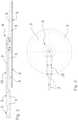
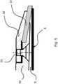
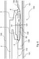
Fig. 1 shows a three dimensional view of an exemplary embodiment of a tool according to the present invention,Fig. 2 shows a sectional view of the tool inFig. 1 ,Fig. 3 shows a top view of the tool inFig. 1 ,Fig. 4 shows a partial and greatly enlarged view of the section inFig. 2 ,Fig. 5 shows a partial and greatly enlarged view of a section of an exemplary embodiment of a tool similar to that inFig. 2 , but which also has an annular element of elastic material, andFig. 6 shows a schematic sectional and out of scale view of a tool according to the present invention within a reaction chamber of an epitaxial reactor while it manipulates a substrate.- Both this description and the drawings are to be considered only for illustrative purposes and therefore non-limiting.
- As it can be easily understood, there are various ways to implement in practice the present invention which is defined in its main advantageous aspects in the appended claims.
- All the figures relate to the same exemplary embodiment of a
tool 1 for manipulating substrates in an epitaxial reactor. Tool 1 comprises anarm 2, agripping disc 3 and a ball joint 4; thegripping disc 3 has aseat 5 on a lower side thereof for receiving asubstrate 6 to be manipulated; thegripping disc 3 is mounted toarm 2 via the ball joint 4 placed centrally with respect to thegripping disc 3.Seat 5 of thegripping disc 3 is shaped so as to come into contact only with the upper edge ofsubstrate 6 to be manipulated. As seen inFig. 2 , in an advantageous example embodiment,seat 5 substantially corresponds to the whole lower side of thegripping disc 3 and to the whole upper side ofsubstrate 6 to be manipulated. As seen inFig. 2 , in an advantageous example embodiment,seat 5 comprises a central cylindrical or prismatical space having a thickness for example of 5-15 mm (which constitutes a "suction cavity" and which serves to produce even suction force, without contact, on the whole upper side of the substrate to manipulate). As seen inFig. 2 , in an advantageous example embodiment,seat 5 comprises an annular truncated-conical or truncated-pyramidal space having a maximum thickness for example of 0.5-1.5 mm (which serves to contact the upper edge of the substrate to be manipulated). As seen inFig. 2 , in an advantageous example embodiment,seat 5 is fully closed when the substrate is manipulated by the tool (i.e. after the so-called "capture").- In first approximation it may be assumed that
arm 2, which is substantially an elongated cylindrical element, during use oftool 1, has its axis arranged horizontally, as seen inFig. 2 and Fig. 3 ;Fig. 4 shows an axis of the ball joint 4 which, therefore, is arranged vertically. - Thanks to the ball joint 4, the
gripping disc 3 is provided with at least two degrees of freedom of rotational movement with respect toarm 1; in this preferred embodiment, the grippingdisc 3 is provided with only two degrees of freedom of rotational movement with respect to arm 1 (in particular,disc 3 cannot rotate about its symmetry axis which is vertical in the figures). In this way,tool 1 is able to adapt to the position of a substrate (indicated withreference numeral 6 inFig. 2 andFig. 4 ) especially when positioned in a pocket of a susceptor of an epitaxial reactor; in fact, the rotation ofdisc 3 leads to obtain co-planarity between the disc and the substrate (and also susceptor); it is a "natural" rotation that is not obtained by means of an actuator, but is induced by the lowering oftool 1. - Considering the figures, it is understood that the freedom of rotation of
disc 3 is limited; for example, it may be +/- 1° or +/- 2° or +/- 3° or +/- 4° or +/- 5° according to two axes (horizontal) orthogonal to each other. Arm 2 internally has a suction conduit 7 and conduit 7 is in communication withseat 5; so,tool 1 is adapted to retain a substrate (indicated withreference numeral 6 inFig. 2 andFig. 4 ) when in contact with disc 3 (and of course when the suction is active).- A
head 15 coupled to the ball joint 4 is located at one end ofarm 2; whilearm 2 is a rod with for example circular cross-section (it may be polygonal or oval or ...),head 15 is thin and large to allow rotation ofdisc 3 without the need of considerably increasing the vertical dimensions of tool 1 (see in particularFig. 2 ); of course, conduit 7 also extends to the end ofhead 15. Disc 3 has a plurality of holes 8 adapted to put conduit 7 into communication with seat 5 (in particular, there are eight holes).- Also arm 2 (precisely, head 15) has a plurality of holes 9 adapted to put conduit 7 into communication with seat 5 (in particular, there are eight holes).
- Therefore, in the suction step, a small amount of gas that is located in
seat 5 first passes through holes 8, then passes through holes 9, and finally ends up in conduit 7 (the actual final destination is a suction system in communication with conduit 7 and not shown in the figures). - A first important aspect of the ball joint 4 is how movements of rotation are possible.
- A second important aspect of the ball joint 4 is how the fluid path between
seat 5 and conduit 7 is sealed or substantially sealed. - In the embodiment of the figures, both these aspects are present.
- The ball joint 4 comprises a first elastic element 10 (in particular, a lip seal - alternatively an annular elastic bellows or an O-ring) placed between arm 2 (precisely, head 15) and the
gripping disc 3; theelastic element 10 is also adapted to provide sealing. - The ball joint 4 comprises an articulation body (set of
elements 13 and 14 inFig. 4 ) and a second annular elastic element 12 (in particular, an O-ring) placed between the articulation body and thegripping disc 3; theelastic element 12 is adapted to also provide sealing as well. - In general, the elastic elements comprised in the spherical joint are typically one or two or three and can be variously arranged therein, depending on the specific realization of the joint. Such elastic elements are used, among other things, for stabilizing the position of the tool gripping disc (possibly also of the substrate transported) during the movement of the tool.
- The
elastic elements - In the example embodiment in
Fig. 4 , the articulation body comprises an articulation disc 13 (in particular, circular) and a joint stem 14 (in particular, cylindrical), for example made in a single piece. Stem 14 has a hole andhead 15 has a hole; a screw 11 is screwed in both of these two holes and serves to fix arm 2 (namely, head 15) and the articulation body to each other; the annularelastic element 12 is placed between thearticulation disc 13, the joint stem 14 and thegripping disc 3. - In the example embodiment in the figures,
elements - The possibility of rotation of the
gripping disc 3 is given by the ball joint 4 and is allowed by the elasticity of the elastic element or the elastic elements present in the ball joint 4. - Typically, the gripping disc rotates simply by contact between the disc and the edge, i.e. there is no actuator to rotate the disc.
- The delicacy of contact between
tool 1 and substrate (indicated withreference numeral 6 inFig. 2 andFig. 4 ) is favored by the softness of the material or materials of the elastic element or elastic elements present in the ball joint 4. Preferably, the weight of the tool rests (entirely) on a movement system of the tool itself, i.e. neither on the substrate nor on the susceptor; in this way, when the gripping disc comes into contact with the edge of the substrate, just a very small force will be sufficient to cause a rotation of the gripping disc; considering the example embodiment in the figures, such a force will only have to overcome the reaction of the elastic elements in the ball joint. - Advantageously, in order to make the weight of the tool not weigh on substrate and susceptor, it can be envisaged to divide the arm (indicated with
reference numeral 2 in the figures) of the tool into two half arms, connect the two half arms by a hinge and associating a spring to the hinge to contrast the downwards rotation of the hinge. - According to the present invention, the manipulation consists in carrying a substrate close to a susceptor and placing the substrate on the susceptor (in particular, in a seat thereof, also called "pocket") and then, taking the substrate (with a deposited layer) from the susceptor (in particular from a seat thereof, also called "pocket") and carrying the substrate away from the susceptor; a tool with a gripping disc is used for manipulation.
- The manipulation method comprises the steps of:
- A) horizontally moving said tool until said gripping disc is at said seat,
- B) lowering said tool until said gripping disc touches at least one point of the upper edge of said substrate (see
Fig. 6 ), - C) continuing lowering said tool until said gripping disc touches all the upper edge of said substrate via a rotation movement (specifically a tilting movement) with respect to a horizontal axis (consider any horizontal axis that is perpendicular to the vertical symmetry axis highlighted in
Fig. 4 and which lies at least partly in thegripping disc 3 at a level between theelastic elements 10 and 12) but via no rotation movement (i.e. being rotatably fixed) with respect to a vertical symmetry axis of said gripping disc, - D) sucking said substrate by means of a suction system of said tool,
- E) raising said tool with said substrate (retained by sucking), and
- F) horizontally moving said tool with said substrate (retained by sucking).
- Step A is an approach step and typically provides an only-horizontal movement. Steps B and C together carry out an auto-leveling between gripping disc and substrate.
- Step D can be defined a "capture" step. If the tool is provided with a "suction cavity" (such as the tool in
Fig. 2 and Fig. 3 ), in step D an even suction force is produced, without contact, on the whole upper side of the substrate to be manipulated. - Step F is a removal step and typically provides an only-horizontal movement.
- In step C, the gripping disc touches the upper edge of the substrate; with good approximation, it is a contact along the whole edge.
- Typically, the gripping disc rotates simply by contact between the disc and the edge, i.e. there is no actuator to rotate the disc.
- Preferably, at least during steps A, B, C, E and F, the weight of the tool rests (entirely) on a movement system of the tool itself, i.e. neither on the substrate nor on the susceptor; in this way, when the gripping disc comes into contact with the edge of the substrate, just a very small force will be sufficient to cause a rotation of the gripping disc; considering the example embodiment in the figures, such a force will only have to overcome the reaction of the elastic elements of the ball joint.
- Unlike the example embodiment in
Fig. 2 and Fig. 3 and as (partially) shown inFig. 5 , the gripping disc (substantially corresponding to body 30) also comprises anannular element 31 of elastic material adapted to come into contact only with the upper edge ofsubstrate 6 to be manipulated - such an annular ring (and the relative installation means) is the only substantial difference with the example inFig. 2 and Fig. 3 . - The annular element can be made in a single piece or a plurality of near pieces. The elastic material may be a polymeric material, in particular adapted to withstand continuous operation at temperatures above 200 °C, for example between 250 °C and 350 °C; in particular, fluorinated or perfluorinated polymers with elastomeric properties may advantageously be used; a particularly suitable material is "Kalrez® 4079" produced by the company Dupont ("Kalrez® 4079" is an elastomer with a Shore A hardness of 75).
- Alternatively, for example, other elastomeric materials capable of withstanding high temperatures, chemical attack (in particular from acids) and quite soft (e.g. Shore A hardness between 50 and 80) may be used.
- The resistance of the material of the annular element allows manipulating relatively ho substrates; for example, in the case of "Kalrez® 4079", substrates may be manipulated at 300 °C (and even beyond). This allows reducing the process cycle time of the epitaxial reactor because the substrates treated may be discharged from the reactor (i.e. extracted from its reaction chamber) when they are still quite hot (i.e. without letting them cool down completely) and without damaging them thanks to the "controlled and delicate" contact only on their edge. The
annular element 31 can be tightened (for example by means of screws 33) between abody 30 of the gripping disc (for example arranged below) and a clamping ring 32 (for example arranged above); this is the example embodiment inFig. 5 . - The
annular element 31 may (substantially) be shaped as a circular crown; theannular element 31 may be (substantially) flat; this is the example embodiment inFig. 5 . Body 30 of the gripping disc and/or the clampingring 32 can be made of quartz or silicon carbide or titanium or stainless steel or a coated aluminum alloy (preferably coated with thermoplastic material), or FRP (in particular, CFRP). In particular, forbody 30 to be particularly light, it may be made of an aluminum alloy (such as alloy 7075, commercially known as "Ergal") coated with thermoplastic material (such as PEEK = polyetheretherketone).- In the example embodiment in
Fig. 5 , as a result of the contact between annular element of the gripping disc and edge of the substrate, the annular element deforms elastically; in particular, such a deformation at any point is small (typically less than 1 or 2 mm) and thus the vertical force exerted by the tool on any point of the substrate (in particular of its edge) is small. - The delicacy of the contact between tool (in particular the
annular element 31 oftool 1 inFig. 5 ) and substrate (inparticular substrate 6 inFig. 5 ) is favored by the softness of the material of the annular element of the tool. - Preferably, also in the example embodiment in
Fig. 5 , the weight of the tool weighs (entirely) on a movement system of the tool itself, i.e. neither on the substrate nor on the susceptor; when the annular element of the gripping disc comes into contact with the substrate edge, just a small force is sufficient to cause the deformation of the annular element while the tool is lowered further. - Later, while the tool rises, the annular element returns to its natural shape thanks to the elasticity of its material.
- The tool in
Fig. 5 is used similarly to that inFig. 2 and Fig. 3 andFig. 4 , but in step C, the annular element may deform slightly and elastically. - The solution shown partially in
Fig. 5 provides for the gripping disc to be mounted to the arm using a ball joint (see for exampleFig. 4 ). - In the example embodiments described, one or more or all
components - As already said, the tool according to the present invention finds particularly advantageous application in epitaxial reactors, particularly those in which the reaction chamber (usually placed horizontally) has a cavity of reduced height, in particular a few centimeters, for example in the range of 2-5 cm, (usually, the height of this kind of cavities is substantially the same in the various parts of the chamber); such an application is shown for example in
Fig. 6 . - According to the present invention, the manipulation consists in transporting a substrate (6 in
Fig. 6 ) near a susceptor (120 inFig. 6 ) and placing the substrate on the susceptor, in particular in a seat thereof generally called "pocket" (130 inFig. 6 ), and then taking the substrate (with a deposited layer) from the susceptor, in particular from the "pocket", and carrying the substrate away from the susceptor. InFig. 6 , the reaction chamber of an epitaxial reactor is globally indicated withreference numeral 100, and thelower wall 101 of quartz and theupper wall 102 of quartz are visible. Inside the chamber there is arotating susceptor 120 shaped as a horizontal disc (typically a solid body made of graphite);susceptor 120 has a plurality ofhorizontal pockets 130 adapted to accommodatesubstrates 6. Typically,susceptor 120 is surrounded by "coating devices" of the chamber which are shown schematically withreference numeral 110 inFig. 6 . Pocket 130 has avertical symmetry axis 131, has a slightly concave bottom 132 (the center is deeper, for example by 1-5 mm, than the outline), and consists of a first higher cylindrical volume 133 (with a thickness of for example, 1-3 mm) and a second lower cylindrical volume 134 (with a thickness of for example, 1-3 mm); the radius ofvolume 134 is less than the radius ofvolume 133, for example by 1-5 mm.- A
substrate 6 is accommodated withinpocket 130; however, its position cannot be known with absolute certainty; the position ofsubstrate 6 can be defined by itssymmetry axis 61 and itsmedian plane 62. In the case ofFig. 6 , the center ofsubstrate 6 is moved laterally with respect to the center ofpocket 130 but, due to theconcave bottom 132 on which it rests,axis 61 ofsubstrate 6 is inclined with respect toaxis 131 ofpocket 130. Fig. 6 schematically shows also a tool according to the present invention comprising anarm 2 and agripping disc 3; the tool is inserted into the reaction chamber so that thegripping disc 3 is aligned withpocket 130; but it is not aligned withsubstrate 6.- The situation in
Fig. 6 corresponds to when the tool is lowered until thegripping disc 3 touches in a point the upper edge ofsubstrate 6, i.e. at the end of step B described above; the contact may occur with body 30 (as inFig. 2 ) or with the annular element 31 (as inFig. 5 ). - Continuing to lower the tool, the
gripping disc 3 tilts (by an angle corresponding to the angle formed byaxes 61 and 131) and touches all the upper edge ofsubstrate 6; the contact between the tool and the substrate is better, i.e. is along a closed line, if there is also an annular element of elastic material (for example,element 31 inFig. 5 ) at the lower edge of the gripping disc.
Claims (14)
- Tool (1) for manipulating substrates in an epitaxial reactor, comprising an arm (2), a gripping disc (3) and a ball joint (4);wherein said gripping disc (3) has a seat (5) on a lower side thereof for receiving a substrate (6) to be manipulated;wherein said gripping disc (3) is mounted to the arm (2) through said ball joint (4) placed centrally with respect to said gripping disc (3);wherein said gripping disc (3) is shaped so as to come into contact only with the upper edge of said substrate (6) to be manipulated;wherein said gripping disc (3) has two degrees of freedom of rotational movement with respect to said arm (1) to allow it to adapt to the position of a substrate (6) in a pocket of a susceptor of an epitaxial reactor.
- Tool (1) according to claim 1, wherein said seat (5) comprises a central cylindrical or prismatic space which forms a suction cavity and which serves to produce an even suction force over the whole upper side of said substrate (6) to be manipulated, and preferably an annular truncated-conical or truncated-pyramidal space which serves to contact the upper edge of said substrate (6) to be manipulated.
- Tool (1) according to claim 1 or 2, wherein said arm (2) internally has a suction conduit (7); wherein said suction conduit (7) is in communication with said seat (5); whereby the tool (1) is adapted to retain a substrate (6) when in contact with said gripping disc (3).
- Tool (1) according to claim 3, wherein said gripping disc (3) has a plurality of holes (8) adapted to put in communication said suction conduit (7) with said seat (5).
- Tool (1) according to claim 2 or 3 or 4, wherein said arm (2) has a plurality of holes (9) adapted to put in communication said suction conduit (7) with said seat (5).
- Tool (1) according to any one of the preceding claims, wherein said ball joint (4) comprises at least one annular spring element (10) placed between said arm (2) and said gripping disc (3).
- Tool (1) according to claims 6 and 3, wherein said spring element (10) is adapted to also provide sealing.
- Tool (1) according to any one of the preceding claims, wherein said ball joint (4) comprises an articulation body and a further annular spring element (12) placed between said articulation body and said gripping disc (3).
- Tool (1) according to claims 8 and 3, wherein said further spring element (12) is adapted to also provide sealing.
- Tool (1) according to claim 8 or 9, wherein said articulation body comprises an articulation disc (13) and a joint stem (14); wherein said further annular spring element (12) is placed between said joint stem (14) and said gripping disc (3).
- Tool (1) according to any one of the preceding claims, wherein said gripping disc (3) comprises an annular element (31) of elastic material adapted to contact the edge of a substrate (6) to be manipulated.
- Tool (1) according to claim 11, wherein said annular element (31) is tightened between a body (30) of said gripping disc (3) and a clamping ring (32) of said gripping disc (3).
- Tool (1) according to claim 11 or 12, wherein said annular element (31) is in the shape of a circular crown and is flat.
- Epitaxial reactor comprising at least one tool (1) according to any one of the preceding claims from 1 to 13.
Applications Claiming Priority (3)
| Application Number | Priority Date | Filing Date | Title |
|---|---|---|---|
| ITMI20141210 | 2014-07-03 | ||
| ITCO2015A000008AITCO20150008A1 (en) | 2015-04-20 | 2015-04-20 | TOOL FOR HANDLING SUBSTRATES AND EPITAXIAL REACTOR |
| PCT/IB2015/054975WO2016001863A1 (en) | 2014-07-03 | 2015-07-02 | Tool for manipulating substrates, manipulation method and epitaxial reactor |
Publications (2)
| Publication Number | Publication Date |
|---|---|
| EP3164884A1 EP3164884A1 (en) | 2017-05-10 |
| EP3164884B1true EP3164884B1 (en) | 2022-02-23 |
Family
ID=53879729
Family Applications (1)
| Application Number | Title | Priority Date | Filing Date |
|---|---|---|---|
| EP15751079.3AActiveEP3164884B1 (en) | 2014-07-03 | 2015-07-02 | Tool for manipulating substrates, manipulation method and epitaxial reactor |
Country Status (5)
| Country | Link |
|---|---|
| US (1) | US10211085B2 (en) |
| EP (1) | EP3164884B1 (en) |
| JP (1) | JP6800022B2 (en) |
| CN (1) | CN106471614B (en) |
| WO (1) | WO2016001863A1 (en) |
Families Citing this family (8)
| Publication number | Priority date | Publication date | Assignee | Title |
|---|---|---|---|---|
| US20170053822A1 (en)* | 2015-08-23 | 2017-02-23 | Camtek Ltd. | Warped wafers vacuum chuck |
| USD803283S1 (en) | 2016-05-16 | 2017-11-21 | Veeco Instruments Inc. | Wafer handling assembly |
| CN108933099B (en)* | 2018-08-01 | 2024-01-05 | 北京北方华创微电子装备有限公司 | Apparatus for handling substrates |
| EP3657537A1 (en)* | 2018-11-23 | 2020-05-27 | ATOTECH Deutschland GmbH | End effector for slab formed substrates |
| JP7576500B2 (en)* | 2021-03-29 | 2024-10-31 | 東京エレクトロン株式会社 | Substrate transport device, state determination method, and computer storage medium |
| IT202100014984A1 (en) | 2021-06-09 | 2022-12-09 | Lpe Spa | REACTION CHAMBER WITH COATING SYSTEM AND EPITAXILE REACTOR |
| IT202200026922A1 (en) | 2022-12-28 | 2024-06-28 | Ima Spa | EQUIPMENT AND PROCEDURE FOR AUTOMATICALLY MOVING OBJECTS WITHIN A CONTROLLED ATMOSPHERE ENVIRONMENT. |
| IT202200026916A1 (en) | 2022-12-28 | 2024-06-28 | Ima Spa | EQUIPMENT AND PROCEDURE FOR AUTOMATICALLY CLOSING CONTAINERS. |
Family Cites Families (29)
| Publication number | Priority date | Publication date | Assignee | Title |
|---|---|---|---|---|
| KR0148714B1 (en) | 1995-08-01 | 1998-08-17 | 황철주 | Susceptor for low pressure chemical vapour deposition apparatus |
| JPH09246365A (en)* | 1996-03-11 | 1997-09-19 | Dainippon Printing Co Ltd | Substrate holding jig |
| US6133152A (en) | 1997-05-16 | 2000-10-17 | Applied Materials, Inc. | Co-rotating edge ring extension for use in a semiconductor processing chamber |
| JP3259251B2 (en)* | 1998-04-27 | 2002-02-25 | 株式会社東京精密 | Wafer planar processing apparatus and planar processing method |
| US6096135A (en) | 1998-07-21 | 2000-08-01 | Applied Materials, Inc. | Method and apparatus for reducing contamination of a substrate in a substrate processing system |
| IT1308606B1 (en)* | 1999-02-12 | 2002-01-08 | Lpe Spa | DEVICE FOR HANDLING SUBSTRATES BY MEANS OF A SELF-LEVELING DEPRESSION SYSTEM IN INDUCTION EPISTAXIAL REACTORS WITH SUCCESSOR |
| US6537011B1 (en) | 2000-03-10 | 2003-03-25 | Applied Materials, Inc. | Method and apparatus for transferring and supporting a substrate |
| JP3408780B2 (en)* | 2000-06-05 | 2003-05-19 | 株式会社しなのエレクトロニクス | Vacuum gripper and IC test handler |
| JP2003100848A (en)* | 2001-09-25 | 2003-04-04 | Applied Materials Inc | Substrate holding device |
| US20030114016A1 (en) | 2001-12-18 | 2003-06-19 | Tischler Michael A. | Wafer carrier for semiconductor process tool |
| DE10232731A1 (en) | 2002-07-19 | 2004-02-05 | Aixtron Ag | Loading and unloading device for a coating device |
| AU2002368438A1 (en) | 2002-12-10 | 2004-06-30 | Etc Srl | Susceptor system________________________ |
| CN1708602A (en) | 2002-12-10 | 2005-12-14 | Etc外延技术中心有限公司 | receptor system |
| US7055875B2 (en)* | 2003-07-11 | 2006-06-06 | Asyst Technologies, Inc. | Ultra low contact area end effector |
| US7771538B2 (en) | 2004-01-20 | 2010-08-10 | Jusung Engineering Co., Ltd. | Substrate supporting means having wire and apparatus using the same |
| US20060275104A1 (en) | 2004-06-09 | 2006-12-07 | E.T.C. Epitaxial Technology Center S R L | Support system for treatment apparatuses |
| ITMI20041677A1 (en) | 2004-08-30 | 2004-11-30 | E T C Epitaxial Technology Ct | CLEANING PROCESS AND OPERATIONAL PROCESS FOR A CVD REACTOR. |
| JP2008514819A (en) | 2004-10-01 | 2008-05-08 | エルピーイー ソシエタ ペル アチオニ | Epitaxial reactor cooling method and reactor cooled thereby |
| ITMI20050645A1 (en) | 2005-04-14 | 2006-10-15 | Lpe Spa | SUSCECTORS FOR EPITAXIAL REACTORS AND TOOL HANDLING |
| ITMI20052498A1 (en) | 2005-12-28 | 2007-06-29 | Lpe Spa | REACTION CHAMBER AT DIFFERENTIATED TEMPERATURE |
| US8752872B2 (en)* | 2009-09-14 | 2014-06-17 | Fabworx Solutions, Inc. | Edge grip end effector |
| DE102010017082A1 (en) | 2010-05-26 | 2011-12-01 | Aixtron Ag | Device and method for loading and unloading, in particular a coating device |
| JP5343954B2 (en)* | 2010-11-01 | 2013-11-13 | 株式会社安川電機 | Substrate transfer hand, substrate transfer apparatus and substrate transfer method including the same |
| JP5846734B2 (en)* | 2010-11-05 | 2016-01-20 | 株式会社ディスコ | Transport device |
| KR101928356B1 (en) | 2012-02-16 | 2018-12-12 | 엘지이노텍 주식회사 | Apparatus for manufacturing semiconductor |
| CN103625922B (en)* | 2012-08-24 | 2016-06-08 | 富泰华工业(深圳)有限公司 | Clamp device |
| JP2014072510A (en)* | 2012-10-02 | 2014-04-21 | Disco Abrasive Syst Ltd | Chuck table |
| JP2014086472A (en)* | 2012-10-19 | 2014-05-12 | Sinfonia Technology Co Ltd | Clamp device and workpiece conveyer robot |
| US9355882B2 (en)* | 2013-12-04 | 2016-05-31 | Taiwan Semiconductor Manufacturing Co., Ltd. | Transfer module for bowed wafers |
- 2015
- 2015-07-02EPEP15751079.3Apatent/EP3164884B1/enactiveActive
- 2015-07-02JPJP2016571737Apatent/JP6800022B2/enactiveActive
- 2015-07-02CNCN201580035249.9Apatent/CN106471614B/enactiveActive
- 2015-07-02WOPCT/IB2015/054975patent/WO2016001863A1/enactiveApplication Filing
- 2016
- 2016-12-20USUS15/385,473patent/US10211085B2/enactiveActive
Also Published As
| Publication number | Publication date |
|---|---|
| CN106471614A (en) | 2017-03-01 |
| CN106471614B (en) | 2020-08-25 |
| US20170103912A1 (en) | 2017-04-13 |
| JP2017522723A (en) | 2017-08-10 |
| US10211085B2 (en) | 2019-02-19 |
| WO2016001863A1 (en) | 2016-01-07 |
| EP3164884A1 (en) | 2017-05-10 |
| JP6800022B2 (en) | 2020-12-16 |
Similar Documents
| Publication | Publication Date | Title |
|---|---|---|
| EP3164884B1 (en) | Tool for manipulating substrates, manipulation method and epitaxial reactor | |
| US11587821B2 (en) | Substrate lift mechanism and reactor including same | |
| EP3363044B1 (en) | Substrate carrier system | |
| CN209471945U (en) | Removable and removable disposal accessories | |
| US10600673B2 (en) | Magnetic susceptor to baseplate seal | |
| CN106463323B (en) | Lift Pin Assembly | |
| EP1968110B1 (en) | High temperature anti-droop end effector for substrate transfer | |
| CN109545642A (en) | In-situ equipment for semiconductor process modules | |
| CN110114866A (en) | Taper chip for semiconductor processes is placed in the middle and holding meanss | |
| JP7469561B2 (en) | Manipulator | |
| CN107749407B (en) | Wafer carrier and its support structure | |
| CN111244019A (en) | Substrate supporting device, substrate transfer robot, and alignment device | |
| WO2015044748A1 (en) | Coated susceptor and anti-bowing method | |
| CN105470176B (en) | Semiconductor film-forming apparatus, substrate automatic positioning clamping structure and method for chucking | |
| US9196471B1 (en) | Scanner for wafers, method for using the scanner, and components of the scanner | |
| CN108728819B (en) | Connecting device and semiconductor processing equipment | |
| ITCO20150008A1 (en) | TOOL FOR HANDLING SUBSTRATES AND EPITAXIAL REACTOR | |
| EP1430516B1 (en) | Tool for handling wafers and epitaxial growth station | |
| CN205452245U (en) | Semiconductor film forming equipment, substrate automatic positioning clamping structure | |
| US10815585B2 (en) | Susceptor with substrate clamped by underpressure, and reactor for epitaxial deposition | |
| JP6587354B2 (en) | Susceptor | |
| WO2009047597A1 (en) | Tool for handling a susceptor, and machine for treating substrates and/or wafers using it |
Legal Events
| Date | Code | Title | Description |
|---|---|---|---|
| STAA | Information on the status of an ep patent application or granted ep patent | Free format text:STATUS: THE INTERNATIONAL PUBLICATION HAS BEEN MADE | |
| PUAI | Public reference made under article 153(3) epc to a published international application that has entered the european phase | Free format text:ORIGINAL CODE: 0009012 | |
| STAA | Information on the status of an ep patent application or granted ep patent | Free format text:STATUS: REQUEST FOR EXAMINATION WAS MADE | |
| 17P | Request for examination filed | Effective date:20170201 | |
| AK | Designated contracting states | Kind code of ref document:A1 Designated state(s):AL AT BE BG CH CY CZ DE DK EE ES FI FR GB GR HR HU IE IS IT LI LT LU LV MC MK MT NL NO PL PT RO RS SE SI SK SM TR | |
| AX | Request for extension of the european patent | Extension state:BA ME | |
| DAV | Request for validation of the european patent (deleted) | ||
| DAX | Request for extension of the european patent (deleted) | ||
| STAA | Information on the status of an ep patent application or granted ep patent | Free format text:STATUS: EXAMINATION IS IN PROGRESS | |
| 17Q | First examination report despatched | Effective date:20201216 | |
| GRAP | Despatch of communication of intention to grant a patent | Free format text:ORIGINAL CODE: EPIDOSNIGR1 | |
| STAA | Information on the status of an ep patent application or granted ep patent | Free format text:STATUS: GRANT OF PATENT IS INTENDED | |
| INTG | Intention to grant announced | Effective date:20211115 | |
| GRAS | Grant fee paid | Free format text:ORIGINAL CODE: EPIDOSNIGR3 | |
| GRAA | (expected) grant | Free format text:ORIGINAL CODE: 0009210 | |
| STAA | Information on the status of an ep patent application or granted ep patent | Free format text:STATUS: THE PATENT HAS BEEN GRANTED | |
| AK | Designated contracting states | Kind code of ref document:B1 Designated state(s):AL AT BE BG CH CY CZ DE DK EE ES FI FR GB GR HR HU IE IS IT LI LT LU LV MC MK MT NL NO PL PT RO RS SE SI SK SM TR | |
| REG | Reference to a national code | Ref country code:GB Ref legal event code:FG4D | |
| REG | Reference to a national code | Ref country code:CH Ref legal event code:EP | |
| REG | Reference to a national code | Ref country code:DE Ref legal event code:R096 Ref document number:602015077081 Country of ref document:DE | |
| REG | Reference to a national code | Ref country code:AT Ref legal event code:REF Ref document number:1471100 Country of ref document:AT Kind code of ref document:T Effective date:20220315 | |
| REG | Reference to a national code | Ref country code:IE Ref legal event code:FG4D | |
| REG | Reference to a national code | Ref country code:LT Ref legal event code:MG9D | |
| REG | Reference to a national code | Ref country code:NL Ref legal event code:MP Effective date:20220223 | |
| REG | Reference to a national code | Ref country code:AT Ref legal event code:MK05 Ref document number:1471100 Country of ref document:AT Kind code of ref document:T Effective date:20220223 | |
| PG25 | Lapsed in a contracting state [announced via postgrant information from national office to epo] | Ref country code:SE Free format text:LAPSE BECAUSE OF FAILURE TO SUBMIT A TRANSLATION OF THE DESCRIPTION OR TO PAY THE FEE WITHIN THE PRESCRIBED TIME-LIMIT Effective date:20220223 Ref country code:RS Free format text:LAPSE BECAUSE OF FAILURE TO SUBMIT A TRANSLATION OF THE DESCRIPTION OR TO PAY THE FEE WITHIN THE PRESCRIBED TIME-LIMIT Effective date:20220223 Ref country code:PT Free format text:LAPSE BECAUSE OF FAILURE TO SUBMIT A TRANSLATION OF THE DESCRIPTION OR TO PAY THE FEE WITHIN THE PRESCRIBED TIME-LIMIT Effective date:20220623 Ref country code:NO Free format text:LAPSE BECAUSE OF FAILURE TO SUBMIT A TRANSLATION OF THE DESCRIPTION OR TO PAY THE FEE WITHIN THE PRESCRIBED TIME-LIMIT Effective date:20220523 Ref country code:NL Free format text:LAPSE BECAUSE OF FAILURE TO SUBMIT A TRANSLATION OF THE DESCRIPTION OR TO PAY THE FEE WITHIN THE PRESCRIBED TIME-LIMIT Effective date:20220223 Ref country code:LT Free format text:LAPSE BECAUSE OF FAILURE TO SUBMIT A TRANSLATION OF THE DESCRIPTION OR TO PAY THE FEE WITHIN THE PRESCRIBED TIME-LIMIT Effective date:20220223 Ref country code:HR Free format text:LAPSE BECAUSE OF FAILURE TO SUBMIT A TRANSLATION OF THE DESCRIPTION OR TO PAY THE FEE WITHIN THE PRESCRIBED TIME-LIMIT Effective date:20220223 Ref country code:ES Free format text:LAPSE BECAUSE OF FAILURE TO SUBMIT A TRANSLATION OF THE DESCRIPTION OR TO PAY THE FEE WITHIN THE PRESCRIBED TIME-LIMIT Effective date:20220223 Ref country code:BG Free format text:LAPSE BECAUSE OF FAILURE TO SUBMIT A TRANSLATION OF THE DESCRIPTION OR TO PAY THE FEE WITHIN THE PRESCRIBED TIME-LIMIT Effective date:20220523 | |
| PG25 | Lapsed in a contracting state [announced via postgrant information from national office to epo] | Ref country code:PL Free format text:LAPSE BECAUSE OF FAILURE TO SUBMIT A TRANSLATION OF THE DESCRIPTION OR TO PAY THE FEE WITHIN THE PRESCRIBED TIME-LIMIT Effective date:20220223 Ref country code:LV Free format text:LAPSE BECAUSE OF FAILURE TO SUBMIT A TRANSLATION OF THE DESCRIPTION OR TO PAY THE FEE WITHIN THE PRESCRIBED TIME-LIMIT Effective date:20220223 Ref country code:GR Free format text:LAPSE BECAUSE OF FAILURE TO SUBMIT A TRANSLATION OF THE DESCRIPTION OR TO PAY THE FEE WITHIN THE PRESCRIBED TIME-LIMIT Effective date:20220524 Ref country code:FI Free format text:LAPSE BECAUSE OF FAILURE TO SUBMIT A TRANSLATION OF THE DESCRIPTION OR TO PAY THE FEE WITHIN THE PRESCRIBED TIME-LIMIT Effective date:20220223 Ref country code:AT Free format text:LAPSE BECAUSE OF FAILURE TO SUBMIT A TRANSLATION OF THE DESCRIPTION OR TO PAY THE FEE WITHIN THE PRESCRIBED TIME-LIMIT Effective date:20220223 | |
| PG25 | Lapsed in a contracting state [announced via postgrant information from national office to epo] | Ref country code:IS Free format text:LAPSE BECAUSE OF FAILURE TO SUBMIT A TRANSLATION OF THE DESCRIPTION OR TO PAY THE FEE WITHIN THE PRESCRIBED TIME-LIMIT Effective date:20220623 | |
| PG25 | Lapsed in a contracting state [announced via postgrant information from national office to epo] | Ref country code:SM Free format text:LAPSE BECAUSE OF FAILURE TO SUBMIT A TRANSLATION OF THE DESCRIPTION OR TO PAY THE FEE WITHIN THE PRESCRIBED TIME-LIMIT Effective date:20220223 Ref country code:SK Free format text:LAPSE BECAUSE OF FAILURE TO SUBMIT A TRANSLATION OF THE DESCRIPTION OR TO PAY THE FEE WITHIN THE PRESCRIBED TIME-LIMIT Effective date:20220223 Ref country code:RO Free format text:LAPSE BECAUSE OF FAILURE TO SUBMIT A TRANSLATION OF THE DESCRIPTION OR TO PAY THE FEE WITHIN THE PRESCRIBED TIME-LIMIT Effective date:20220223 Ref country code:EE Free format text:LAPSE BECAUSE OF FAILURE TO SUBMIT A TRANSLATION OF THE DESCRIPTION OR TO PAY THE FEE WITHIN THE PRESCRIBED TIME-LIMIT Effective date:20220223 Ref country code:DK Free format text:LAPSE BECAUSE OF FAILURE TO SUBMIT A TRANSLATION OF THE DESCRIPTION OR TO PAY THE FEE WITHIN THE PRESCRIBED TIME-LIMIT Effective date:20220223 Ref country code:CZ Free format text:LAPSE BECAUSE OF FAILURE TO SUBMIT A TRANSLATION OF THE DESCRIPTION OR TO PAY THE FEE WITHIN THE PRESCRIBED TIME-LIMIT Effective date:20220223 | |
| REG | Reference to a national code | Ref country code:DE Ref legal event code:R097 Ref document number:602015077081 Country of ref document:DE | |
| PG25 | Lapsed in a contracting state [announced via postgrant information from national office to epo] | Ref country code:AL Free format text:LAPSE BECAUSE OF FAILURE TO SUBMIT A TRANSLATION OF THE DESCRIPTION OR TO PAY THE FEE WITHIN THE PRESCRIBED TIME-LIMIT Effective date:20220223 | |
| PLBE | No opposition filed within time limit | Free format text:ORIGINAL CODE: 0009261 | |
| STAA | Information on the status of an ep patent application or granted ep patent | Free format text:STATUS: NO OPPOSITION FILED WITHIN TIME LIMIT | |
| 26N | No opposition filed | Effective date:20221124 | |
| PG25 | Lapsed in a contracting state [announced via postgrant information from national office to epo] | Ref country code:SI Free format text:LAPSE BECAUSE OF FAILURE TO SUBMIT A TRANSLATION OF THE DESCRIPTION OR TO PAY THE FEE WITHIN THE PRESCRIBED TIME-LIMIT Effective date:20220223 Ref country code:MC Free format text:LAPSE BECAUSE OF FAILURE TO SUBMIT A TRANSLATION OF THE DESCRIPTION OR TO PAY THE FEE WITHIN THE PRESCRIBED TIME-LIMIT Effective date:20220223 | |
| REG | Reference to a national code | Ref country code:CH Ref legal event code:PL | |
| REG | Reference to a national code | Ref country code:BE Ref legal event code:MM Effective date:20220731 | |
| PG25 | Lapsed in a contracting state [announced via postgrant information from national office to epo] | Ref country code:LU Free format text:LAPSE BECAUSE OF NON-PAYMENT OF DUE FEES Effective date:20220702 Ref country code:LI Free format text:LAPSE BECAUSE OF NON-PAYMENT OF DUE FEES Effective date:20220731 Ref country code:CH Free format text:LAPSE BECAUSE OF NON-PAYMENT OF DUE FEES Effective date:20220731 | |
| PG25 | Lapsed in a contracting state [announced via postgrant information from national office to epo] | Ref country code:BE Free format text:LAPSE BECAUSE OF NON-PAYMENT OF DUE FEES Effective date:20220731 | |
| PG25 | Lapsed in a contracting state [announced via postgrant information from national office to epo] | Ref country code:IE Free format text:LAPSE BECAUSE OF NON-PAYMENT OF DUE FEES Effective date:20220702 | |
| PG25 | Lapsed in a contracting state [announced via postgrant information from national office to epo] | Ref country code:HU Free format text:LAPSE BECAUSE OF FAILURE TO SUBMIT A TRANSLATION OF THE DESCRIPTION OR TO PAY THE FEE WITHIN THE PRESCRIBED TIME-LIMIT; INVALID AB INITIO Effective date:20150702 | |
| PG25 | Lapsed in a contracting state [announced via postgrant information from national office to epo] | Ref country code:MK Free format text:LAPSE BECAUSE OF FAILURE TO SUBMIT A TRANSLATION OF THE DESCRIPTION OR TO PAY THE FEE WITHIN THE PRESCRIBED TIME-LIMIT Effective date:20220223 Ref country code:CY Free format text:LAPSE BECAUSE OF FAILURE TO SUBMIT A TRANSLATION OF THE DESCRIPTION OR TO PAY THE FEE WITHIN THE PRESCRIBED TIME-LIMIT Effective date:20220223 | |
| PG25 | Lapsed in a contracting state [announced via postgrant information from national office to epo] | Ref country code:TR Free format text:LAPSE BECAUSE OF FAILURE TO SUBMIT A TRANSLATION OF THE DESCRIPTION OR TO PAY THE FEE WITHIN THE PRESCRIBED TIME-LIMIT Effective date:20220223 | |
| PG25 | Lapsed in a contracting state [announced via postgrant information from national office to epo] | Ref country code:MT Free format text:LAPSE BECAUSE OF FAILURE TO SUBMIT A TRANSLATION OF THE DESCRIPTION OR TO PAY THE FEE WITHIN THE PRESCRIBED TIME-LIMIT Effective date:20220223 | |
| PGFP | Annual fee paid to national office [announced via postgrant information from national office to epo] | Ref country code:DE Payment date:20240729 Year of fee payment:10 | |
| PGFP | Annual fee paid to national office [announced via postgrant information from national office to epo] | Ref country code:GB Payment date:20240729 Year of fee payment:10 | |
| PGFP | Annual fee paid to national office [announced via postgrant information from national office to epo] | Ref country code:FR Payment date:20240725 Year of fee payment:10 | |
| PGFP | Annual fee paid to national office [announced via postgrant information from national office to epo] | Ref country code:IT Payment date:20240719 Year of fee payment:10 |