EP3161520B1 - Compressive scanning lidar - Google Patents
Compressive scanning lidarDownload PDFInfo
- Publication number
- EP3161520B1 EP3161520B1EP14896260.8AEP14896260AEP3161520B1EP 3161520 B1EP3161520 B1EP 3161520B1EP 14896260 AEP14896260 AEP 14896260AEP 3161520 B1EP3161520 B1EP 3161520B1
- Authority
- EP
- European Patent Office
- Prior art keywords
- laser
- pixel
- spot
- mask
- received light
- Prior art date
- Legal status (The legal status is an assumption and is not a legal conclusion. Google has not performed a legal analysis and makes no representation as to the accuracy of the status listed.)
- Active
Links
Images


Classifications
- G—PHYSICS
- G01—MEASURING; TESTING
- G01S—RADIO DIRECTION-FINDING; RADIO NAVIGATION; DETERMINING DISTANCE OR VELOCITY BY USE OF RADIO WAVES; LOCATING OR PRESENCE-DETECTING BY USE OF THE REFLECTION OR RERADIATION OF RADIO WAVES; ANALOGOUS ARRANGEMENTS USING OTHER WAVES
- G01S7/00—Details of systems according to groups G01S13/00, G01S15/00, G01S17/00
- G01S7/48—Details of systems according to groups G01S13/00, G01S15/00, G01S17/00 of systems according to group G01S17/00
- G01S7/481—Constructional features, e.g. arrangements of optical elements
- G01S7/4817—Constructional features, e.g. arrangements of optical elements relating to scanning
- G—PHYSICS
- G01—MEASURING; TESTING
- G01S—RADIO DIRECTION-FINDING; RADIO NAVIGATION; DETERMINING DISTANCE OR VELOCITY BY USE OF RADIO WAVES; LOCATING OR PRESENCE-DETECTING BY USE OF THE REFLECTION OR RERADIATION OF RADIO WAVES; ANALOGOUS ARRANGEMENTS USING OTHER WAVES
- G01S17/00—Systems using the reflection or reradiation of electromagnetic waves other than radio waves, e.g. lidar systems
- G01S17/02—Systems using the reflection of electromagnetic waves other than radio waves
- G01S17/06—Systems determining position data of a target
- G01S17/08—Systems determining position data of a target for measuring distance only
- G01S17/32—Systems determining position data of a target for measuring distance only using transmission of continuous waves, whether amplitude-, frequency-, or phase-modulated, or unmodulated
- G01S17/34—Systems determining position data of a target for measuring distance only using transmission of continuous waves, whether amplitude-, frequency-, or phase-modulated, or unmodulated using transmission of continuous, frequency-modulated waves while heterodyning the received signal, or a signal derived therefrom, with a locally-generated signal related to the contemporaneously transmitted signal
- G—PHYSICS
- G01—MEASURING; TESTING
- G01S—RADIO DIRECTION-FINDING; RADIO NAVIGATION; DETERMINING DISTANCE OR VELOCITY BY USE OF RADIO WAVES; LOCATING OR PRESENCE-DETECTING BY USE OF THE REFLECTION OR RERADIATION OF RADIO WAVES; ANALOGOUS ARRANGEMENTS USING OTHER WAVES
- G01S17/00—Systems using the reflection or reradiation of electromagnetic waves other than radio waves, e.g. lidar systems
- G01S17/88—Lidar systems specially adapted for specific applications
- G01S17/89—Lidar systems specially adapted for specific applications for mapping or imaging
- G—PHYSICS
- G01—MEASURING; TESTING
- G01S—RADIO DIRECTION-FINDING; RADIO NAVIGATION; DETERMINING DISTANCE OR VELOCITY BY USE OF RADIO WAVES; LOCATING OR PRESENCE-DETECTING BY USE OF THE REFLECTION OR RERADIATION OF RADIO WAVES; ANALOGOUS ARRANGEMENTS USING OTHER WAVES
- G01S7/00—Details of systems according to groups G01S13/00, G01S15/00, G01S17/00
- G01S7/48—Details of systems according to groups G01S13/00, G01S15/00, G01S17/00 of systems according to group G01S17/00
- G01S7/4808—Evaluating distance, position or velocity data
- H—ELECTRICITY
- H01—ELECTRIC ELEMENTS
- H01S—DEVICES USING THE PROCESS OF LIGHT AMPLIFICATION BY STIMULATED EMISSION OF RADIATION [LASER] TO AMPLIFY OR GENERATE LIGHT; DEVICES USING STIMULATED EMISSION OF ELECTROMAGNETIC RADIATION IN WAVE RANGES OTHER THAN OPTICAL
- H01S5/00—Semiconductor lasers
- H01S5/02—Structural details or components not essential to laser action
- H01S5/0206—Substrates, e.g. growth, shape, material, removal or bonding
- H01S5/021—Silicon based substrates
- H—ELECTRICITY
- H01—ELECTRIC ELEMENTS
- H01S—DEVICES USING THE PROCESS OF LIGHT AMPLIFICATION BY STIMULATED EMISSION OF RADIATION [LASER] TO AMPLIFY OR GENERATE LIGHT; DEVICES USING STIMULATED EMISSION OF ELECTROMAGNETIC RADIATION IN WAVE RANGES OTHER THAN OPTICAL
- H01S5/00—Semiconductor lasers
- H01S5/02—Structural details or components not essential to laser action
- H01S5/0206—Substrates, e.g. growth, shape, material, removal or bonding
- H01S5/0215—Bonding to the substrate
- H—ELECTRICITY
- H01—ELECTRIC ELEMENTS
- H01S—DEVICES USING THE PROCESS OF LIGHT AMPLIFICATION BY STIMULATED EMISSION OF RADIATION [LASER] TO AMPLIFY OR GENERATE LIGHT; DEVICES USING STIMULATED EMISSION OF ELECTROMAGNETIC RADIATION IN WAVE RANGES OTHER THAN OPTICAL
- H01S5/00—Semiconductor lasers
- H01S5/02—Structural details or components not essential to laser action
- H01S5/026—Monolithically integrated components, e.g. waveguides, monitoring photo-detectors, drivers
- H01S5/0262—Photo-diodes, e.g. transceiver devices, bidirectional devices
- H—ELECTRICITY
- H01—ELECTRIC ELEMENTS
- H01S—DEVICES USING THE PROCESS OF LIGHT AMPLIFICATION BY STIMULATED EMISSION OF RADIATION [LASER] TO AMPLIFY OR GENERATE LIGHT; DEVICES USING STIMULATED EMISSION OF ELECTROMAGNETIC RADIATION IN WAVE RANGES OTHER THAN OPTICAL
- H01S5/00—Semiconductor lasers
- H01S5/10—Construction or shape of the optical resonator, e.g. extended or external cavity, coupled cavities, bent-guide, varying width, thickness or composition of the active region
- H01S5/12—Construction or shape of the optical resonator, e.g. extended or external cavity, coupled cavities, bent-guide, varying width, thickness or composition of the active region the resonator having a periodic structure, e.g. in distributed feedback [DFB] lasers
Definitions
- This disclosurerelates to Light Detection And Ranging (LIDAR or lidar), and in particular scanning lidars.
- LIDARLight Detection And Ranging
- Existing real-time lidar systemsconsist of two general types.
- the first typeconsists of large and expensive mechanically scanned lidar systems such as the Velodyne-64, marketed by Velodyne Lidar, Inc.
- Such mechanically scanned lidar systemsuse large rotating mirrors to scan multiple laser beams and use time of flight detection of reflected laser pulses to measure the range of each spot along the beam directions.
- the second typeconsists of flash lidars that illuminate the entire scene with each pulse and use an array of time-gated photodiodes to image the reflected light and measure the range for each pixel.
- Rotating mirror LIDAR systemsare large, heavy, power-hungry, and have poor angular resolution in the elevation direction, which is limited by the number of laser beams, for example, 64 beams in the case of the Velodyne-64 lidar.
- the azimuth resolutionis limited by the laser spot size.
- Flash lidar systemshave limited range because the laser pulse power is spread out over the entire scene, which greatly reduces the amount of power reflected by an object and captured by the detector aperture.
- the flash lidar angular resolution and field of vieware limited by the number of time-gated photodiodes in the detector array.
- a lidar with reduced size weight and powerthat has an improved field of view (FOV), range resolution, and angular resolution. Also needed is a lidar that enables imaging different parts of the 3D scene with variable resolution, thereby allowing high angular resolution 3D imaging of the most salient or important regions of interest while maintaining a high frame rate and keeping the computational load low.
- a method for increasing resolution of an image formed of received light from an illuminated spotis disclosed according to claim 1.
- a LIDAR systemis disclosed according to claim 9.
- a LIDARcomprises the apparatus of claim 9, a scanning laser for scanning a scene and illuminating a spot in the scene; a photodiode detector for detecting received light reflected from the scene; a programmable N-pixel mirror or mask array in an optical path of reflected received light, the programmable N-pixel mirror or mask array optically coupled to the photodiode detector; and means for forming a reconstructed image comprising compressive sensing or Moore-Penrose reconstruction.
- the present disclosureis for a compact and low cost real-time LIDAR sensing system that utilizes a scanned laser beam, programmable micromirror array, detection using a single photodiode, and reconstruction using compressive sensing methods to sense a 3D representation of a scene with large field of view and angular resolution that is not limited by the laser spot size.
- Multiple photodiodesmay also be used by dividing the imaged spot into sections and using one photodiode per section in order to speed up processing using parallel computing.
- This approachalso allows imaging different parts of the 3D scene with variable angular resolution, thereby allowing high resolution imaging of the most salient or important regions of interest while maintaining a high frame rate and keeping the computational load low.
- the SWAP and cost for a lidar in accordance with the present disclosureis much smaller than existing rotating mirror systems and the angular resolution and field of view is much greater than existing flash LIDAR systems based on imaging detector arrays.
- the resolutioncan also be adapted to different regions of interest in the scene, which greatly increases the optical and computational efficiency of the system.
- the compressive sensing lidar of the present disclosurecombines the light efficiency and large field of view of mechanically scanned mirror systems with high resolution reconstruction of the 3D scene in all three dimensions of azimuth, elevation, and range, all in a compact and low cost package based on micro-mirror array technology and compressive sensing reconstruction methods.
- FMCWfrequency modulation continuous wave
- heterodyne detectionusing a single photodiode combined with compressive sensing reconstruction algorithms, a 3D scene can be sensed with an angular resolution that is not limited by the laser spot size or the number of detector elements.
- FIG. 1U.S. Patent Application Serial No. 14/317,695, filed June 27, 2014 , describes a micro-elecro-mechanical system (MEMS) micromirror scanned LIDAR system, which is a low cost and low SWAP alternative to prior art real-time LIDAR systems.
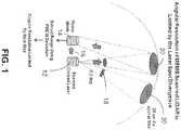
- the operation of the scanned lidar systemis shown in FIG. 1 .
- the systemutilizes a scanned laser 12, frequency modulation continuous wave (FMCW) modulation of the laser, a single photodiode 14, and coherent detection 16 of the FMCW modulation to measure the range of targets individual 3D (three dimensional) resolution elements.
- FMCWfrequency modulation continuous wave
- Both the transmitted laser pulse and receiver apertureare scanned synchronously in azimuth and elevation using dual-axis micromirrors to maximize the signal to noise ratio (SNR).
- SNRsignal to noise ratio
- the angular resolution of the MEMS scanned mirror systemis limited by the laser spot divergence. For a typical laser divergence 18 of 0.2 degrees, this results in a 20cm diameter spot 20 at a range of 50m. While this is sufficient for detecting an object the size of a pedestrian, many applications such as object recognition require finer resolution at larger ranges.
- FIG. 2shows a scanning laser using compressive sensing in accordance with the present disclosure.
- a programmable N -mirror MEMS mirror array or a programmable N-pixel mask 26is used in the receiver aperture in order to perform compressive measurements using the same basic architecture as described in FIG. 1 .
- the programmable N-mirror MEMS mirror array or a programmable N-pixel mask 26may be implemented as a MEMS.
- the programmable micromirror array 26may be an N-pixel micromirror array, such as the Digital Micromirror Device (DMD) made by Texas Instruments.
- DMDDigital Micromirror Device
- FIG. 3shows a compressive sensing scanned LIDAR architecture in accordance with the present disclosure.
- a laser 12is modulated by a linear chirp in frequency by chirped laser pulse signal 30.
- the emitted beam with power ⁇ ⁇may be reflected from mirror 32 to a dual-axis micromirror 34, which scans the emitted beam 36 across the scene.
- Part of the beam 38 with power ⁇ lois mixed for coherent detection with the returned light from the scene at the photodiode detector 14.
- the light from the laser 12, which may as shown in FIG. 2have a beamwidth of 0.2 degrees, illuminates a small spot on the scene.
- the reflection 40 from the sceneis directed by a receiver programmable N-pixel mirror array 42, or a programmable N-pixel mask 42, either one of which may be a microelectromechanical systems (MEMS), to a lens 44, which focuses the spot onto the photodiode 14.
- MEMSmicroelectromechanical systems
- the receiver programmable mirror or mask array 42is synchronized with the dual axis micromirror 34, which may also be a microelectromechanical system (MEMS), to maintain the reflection 40 from the scanned beam 36 focused on the photodiode 14.
- the received reflected laser scene spot 40may be represented by f ( ⁇ , ⁇ ) ⁇ o 40, as shown in FIGs. 3 and 4 , where f ( ⁇ , ⁇ ) is the reflectivity of the scene illuminated by the emitted laser beam 36 with power ⁇ ⁇ , and ⁇ and ⁇ are the azimuth and elevation angles, respectively.
- the received reflected laser scene spot 40is multiplied in the receiver programmable mirror or mask array 42 by a measurement kernel A j 46, to form a product 43, as shown in FIG. 4 , of the received reflected laser scene spot and each measurement kernel A j 46.
- the measurement kernelmay be binary, which means that each pixel in the N-pixel micromirror or mask 42 may be set to be on in order to pass light to the photodiode 14, or off in order to block light for that pixel from the photodiode 14.
- the "on” and "off” statescorrespond to different tilt angles of each micromirror.
- the binary measurement kernels A j 46can be implemented by programming some of the N micromirrors in the receiver programmable mirror array 42 to tilt the light away from the receiver lens aperture 44, or by programming a N-pixel programmable mask so that some areas of the returned light are masked and some areas of the mask are transparent to the returned light.
- Temporal modulation of individual mirrors or masks in the receiver programmable mirror or mask array 42may be used to implement measurement kernels A j 46 with multi-valued elements.
- a pixelmay be set on for a time t1 and off for a time t2, and the result integrated by the photodiode to implement a measurement kernels A j 46 with a non-binary value.
- the photodiode 14performs spatial integration of A j f ( ⁇ , ⁇ ) ⁇ o , forming the inner-product measurement y ⁇ o 48, as shown in FIGs. 3 and 4 , where y is the inner product of the scene reflectivity f ( ⁇ , ⁇ ) with the measurement kernel A j . ⁇ o is the output laser power.
- yis the inner product of the scene reflectivity f ( ⁇ , ⁇ ) with the measurement kernel A j
- ⁇ ois the output laser power
- ⁇ lois the local oscillator power
- ⁇ b and ⁇are a beat frequency 41, as shown in FIG.
- FIG. 5Ashows the frequencies of the emitted laser beam 36 and the received reflected scene spot 40
- FIG. 5Bshows the corresponding beat frequency 41 of the emitted laser beam mixed with the received reflected scene.
- FMCW coherent detection 50can use the equations below to determine parameters of the target spot components, including the range R a , the range uncertainty ⁇ R a , and the velocity v t , where f 1 is the frequency of the emitted beam 36, and f 2 is the frequency of the received reflected laser scene spot 40, as shown in FIG. 5A .
- y for measurement kernel A jcan be measured for each range bin r i , where y is the inner product of the scene reflectivity f ( ⁇ , ⁇ ) with the measurement kernel A j .
- reconstruction of the spot illuminated and reflected from the targetmay be performed using compressive sensing reconstruction 56 or by a Moore-Penrose reconstruction of the spot 57, shown in FIG. 3 .
- the Moore-Penrose inverse A +can be precomputed.
- the advantage of using the Moore-Penrose inverseis that sparsity is not required and the reconstruction consists of simple matrix-vector multiplication, which can be performed very quickly.
- the disadvantageis that more measurements are required than for compressive sensing.
- the result of the reconstructionis a 3D reconstruction of the spot 60.
- Each range slice 58represent the beat frequency components at a particular range in the photodiode signal i(t)as determined by FMCW coherent detection 50, and FFT 52.
- the resolution and quality of the reconstructed 3D spotdepends on both N and M. Since the number of reconstructed pixels in a range slice image is equal to N, relatively small values of N and M will increase the resolution by a large factor over the non-compressive system, whose resolution is limited by by the laser spot size.
- the emitted beam 36is scanned to successive spots in the scene and each successive spot reconstructed.
- step 100the first measurement kernel is loaded, then in step 102 the programmable N-pixel micromirror or mask 42 is programmed with the first measurement kernel A 1 46 for the first measurement of a received reflected scene spot 40.
- step 104the inner product of the scene reflectivity f ( ⁇ , ⁇ ) with the measurement kernel A 1 , is measured and extracted using FMCW coherent detection 50, FFT processing 52, and block 54 for each range bin r i .
- Steps 102 and 104are then repeated for the received reflected scene spot 40 for each measurement kernel A j , until in step 106 it is determined that y has been measured and extracted using all of the measurement kernels A 1 to A M .
- step 110it is determined whether the reconstructed spot is the last spot position. If not, then steps 100, 102, 104, 106, and 108 are repeated for the next spot position. If the reconstructed spot is the last spot position, then the laser scanned 3D scene image has been reconstructed.
- All computations and controls that are needed for the FMCW 50, the FFT 52, extracting y measurements 54, compressive sensing 56, Moore-Penrose reconstruction of the spot 57, and 3D spot reconstruction 60, control of the programmable micromirror or mask array 42, and execution of the process shown in FIG. 6 , as well as any other computations or controls needed for the present disclosuremay be provided by any processor, such as but not limited to a computer, a processor, a microprocessor, a microcomputer, or any element capable of performing computations and storing results of the computation.
- the compressive sensing scanned LIDAR systemincludes much lower size, weight and power (SWAP) and lower cost than mechanically scanned LIDAR systems.
- the compressive sensing LIDARalso has higher angular resolution, field of view, and optical efficiency than flash LIDAR systems which need to illuminate the entire scene at once.
- the number of resolvable spots in azimuth and elevationis increased by a factor of N, where N is the number of mirrors or masks in the receiver MEMS micromirror array or mask array. Even arrays with small N will increase the resolution by a large factor while keeping the computational load low. Since the range slice images are reconstructed independently, multiple slices can be reconstructed in parallel using multi-core processing architectures. Also, both scene reflectance and 3D structure are measured simultaneously and automatically registered.
- the azimuth and elevation angular resolutioncan be adapted for each part of the scene by varying the effective receiver micromirror or mask array resolution ( N ) and the number of measurements ( M ) in order to optimize the resolution of important regions of interest while maintaining the update rate.
- the programmable micromirror or mask array 42may be programmed so that N is decreased to attain lower resolution.
- Regions of interest (ROIs)can be detected using algorithms operating on low resolution sampling of a wide field of view. The ROIs may then be resampled or scanned using a higher N for high resolution which maintains the update rate at the high value associated with low resolution sampling while having the benefit of high resolution on the ROIs for recognition purposes.
- the resolutioncan be increased for ROIs without changing the spot scanning pattern by varying N and M.
- Composite resolution measurement kernelscan be used to implement variable resolution within a spot in order to further reduce the number of measurements needed.
Landscapes
- Physics & Mathematics (AREA)
- Engineering & Computer Science (AREA)
- General Physics & Mathematics (AREA)
- Electromagnetism (AREA)
- Radar, Positioning & Navigation (AREA)
- Remote Sensing (AREA)
- Computer Networks & Wireless Communication (AREA)
- Condensed Matter Physics & Semiconductors (AREA)
- Optics & Photonics (AREA)
- Optical Radar Systems And Details Thereof (AREA)
- Semiconductor Lasers (AREA)
- Optical Integrated Circuits (AREA)
- Optical Couplings Of Light Guides (AREA)
Description
- This disclosure relates to Light Detection And Ranging (LIDAR or lidar), and in particular scanning lidars.
- Existing real-time lidar systems consist of two general types. The first type consists of large and expensive mechanically scanned lidar systems such as the Velodyne-64, marketed by Velodyne Lidar, Inc. Such
mechanically scanned lidar systems use large rotating mirrors to scan multiple laser beams and use time of flight detection of reflected laser pulses to measure the range of each spot along the beam directions. The second type consists of flash lidars that illuminate the entire scene with each pulse and use an array of time-gated photodiodes to image the reflected light and measure the range for each pixel. - Rotating mirror LIDAR systems are large, heavy, power-hungry, and have poor angular resolution in the elevation direction, which is limited by the number of laser beams, for example, 64 beams in the case of the Velodyne-64 lidar. The azimuth resolution is limited by the laser spot size. Flash lidar systems have limited range because the laser pulse power is spread out over the entire scene, which greatly reduces the amount of power reflected by an object and captured by the detector aperture. In addition, the flash lidar angular resolution and field of view are limited by the number of time-gated photodiodes in the detector array.
- Howland et Al.; "Photon-counting compressive sensing laser radar for 3D imaging". Applied Optics, Optical Society of America, Washington DC, US; vol. 50, No. 31, 1 November 2011, pages 5917-5920; ISSN 0003-6935) discloses a photon-counting, single-pixel, laser radar camera for 3D imaging where transverse spatial resolution is obtained through compressive sensing without scanning. This technique is used to image through partially obscuring objects, such as camouflage netting. Our imple¬mentation improves upon pixel-array based designs with a compact, resource-efficient design and highly scalable resolution
- What is needed is a lidar with reduced size weight and power (SWAP) that has an improved field of view (FOV), range resolution, and angular resolution. Also needed is a lidar that enables imaging different parts of the 3D scene with variable resolution, thereby allowing high
angular resolution 3D imaging of the most salient or important regions of interest while maintaining a high frame rate and keeping the computational load low. The embodiments of the present disclosure address these and other needs. - In a first embodiment disclosed herein, a method for increasing resolution of an image formed of received light from an illuminated spot is disclosed according to claim 1.
- In another embodiment disclosed herein, a LIDAR system is disclosed according to claim 9.
- In another embodiment disclosed herein, a LIDAR comprises the apparatus of claim 9, a scanning laser for scanning a scene and illuminating a spot in the scene; a photodiode detector for detecting received light reflected from the scene; a programmable N-pixel mirror or mask array in an optical path of reflected received light, the programmable N-pixel mirror or mask array optically coupled to the photodiode detector; and means for forming a reconstructed image comprising compressive sensing or Moore-Penrose reconstruction.
- These and other features and advantages will become further apparent from the detailed description and accompanying figures that follow. In the figures and description, numerals indicate the various features, like numerals referring to like features throughout both the drawings and the description.
FIG. 1 shows a scanned LIDAR in accordance with (L&P 628659-9) in which the angular resolution is limited by the laser spot divergence;FIG. 2 shows a scanned LIDAR in which the angular resolution is improved by a factor of N using compressive sensing in accordance with the present disclosure;FIG. 3 shows a compressive sensing scanned lidar architecture in accordance with the present disclosure;FIG. 4 shows a process for forming an inner product of a scene spot and a measurement kernel in accordance with the present disclosure;FIG. 5A shows the frequencies of the emitted laser beam and the received reflected scene spot, andFIG. 5B shows the corresponding beat frequency of emitted laser beam beat with the received reflected scene in accordance with the present disclosure; andFIG. 6 shows a processing flow for reconstruction of a 3D scene frame in accordance with the present disclosure.- In the following description, numerous specific details are set forth to clearly describe various specific embodiments disclosed herein. One skilled in the art, however, will understand that the presently claimed invention may be practiced without all of the specific details discussed below. In other instances, well known features have not been described so as not to obscure the invention.
- The present disclosure is for a compact and low cost real-time LIDAR sensing system that utilizes a scanned laser beam, programmable micromirror array, detection using a single photodiode, and reconstruction using compressive sensing methods to sense a 3D representation of a scene with large field of view and angular resolution that is not limited by the laser spot size. Multiple photodiodes may also be used by dividing the imaged spot into sections and using one photodiode per section in order to speed up processing using parallel computing.
- This approach also allows imaging different parts of the 3D scene with variable angular resolution, thereby allowing high resolution imaging of the most salient or important regions of interest while maintaining a high frame rate and keeping the computational load low.
- Compressive sensing has been described by RichardG. Baraniuk in "Compressive Sensing", IEEE Signal Processing Magazine pages 118-120 & page 124 July 2007, which is incorporated herein as though set forth in full and has been attached as Appendix A (beginning on page 27 of this application).
- The SWAP and cost for a lidar in accordance with the present disclosure is much smaller than existing rotating mirror systems and the angular resolution and field of view is much greater than existing flash LIDAR systems based on imaging detector arrays. The resolution can also be adapted to different regions of interest in the scene, which greatly increases the optical and computational efficiency of the system.
- The compressive sensing lidar of the present disclosure combines the light efficiency and large field of view of mechanically scanned mirror systems with high resolution reconstruction of the 3D scene in all three dimensions of azimuth, elevation, and range, all in a compact and low cost package based on micro-mirror array technology and compressive sensing reconstruction methods. By using frequency modulation continuous wave (FMCW) modulation and heterodyne detection using a single photodiode combined with compressive sensing reconstruction algorithms, a 3D scene can be sensed with an angular resolution that is not limited by the laser spot size or the number of detector elements.
U.S. Patent Application Serial No. 14/317,695, filed June 27, 2014 FIG. 1 . The system utilizes a scannedlaser 12, frequency modulation continuous wave (FMCW)
modulation of the laser, asingle photodiode 14, andcoherent detection 16 of the FMCW modulation to measure the range of targets individual 3D (three dimensional) resolution elements. Both the transmitted laser pulse and receiver aperture are scanned synchronously in azimuth and elevation using dual-axis micromirrors to maximize the signal to noise ratio (SNR). As shown inFIG. 1 , the angular resolution of the MEMS scanned mirror system is limited by the laser spot divergence. For atypical laser divergence 18 of 0.2 degrees, this results in a20cm diameter spot 20 at a range of 50m. While this is sufficient for detecting an object the size of a pedestrian, many applications such as object recognition require finer resolution at larger ranges.FIG. 2 shows a scanning laser using compressive sensing in accordance with the present disclosure. A programmableN-mirror MEMS mirror array or a programmable N-pixel mask 26 is used in the receiver aperture in order to perform compressive measurements using the same basic architecture as described inFIG. 1 . The programmable N-mirror MEMS mirror array or a programmable N-pixel mask 26 may be implemented as a MEMS. By using nonlinear compressive sensing reconstruction methods the angular resolution may be increased by a factor of N in the number of resolvable azimuth and elevation angles. Theprogrammable micromirror array 26 may be an N-pixel micromirror array, such as the Digital Micromirror Device (DMD) made by Texas Instruments.FIG. 3 shows a compressive sensing scanned LIDAR architecture in accordance with the present disclosure. Alaser 12 is modulated by a linear chirp in frequency by chirpedlaser pulse signal 30. The emitted beam with power Φο may be reflected frommirror 32 to a dual-axis micromirror 34, which scans the emittedbeam 36 across the scene. Part of thebeam 38 with power Φlo is mixed for coherent detection with the returned light from the scene at thephotodiode detector 14. The light from thelaser 12, which may as shown inFIG. 2 have a beamwidth of 0.2 degrees, illuminates a small spot on the scene. Thereflection 40 from the scene is directed by a receiver programmable N-pixel mirror array 42, or a programmable N-pixel mask 42, either one of which may be a microelectromechanical systems (MEMS), to alens 44, which focuses the spot onto thephotodiode 14. The receiver programmable mirror ormask array 42 is synchronized with thedual axis micromirror 34, which may also be a microelectromechanical system (MEMS), to maintain thereflection 40 from the scannedbeam 36 focused on thephotodiode 14.- The received reflected
laser scene spot 40 may be represented byf(α,β) Φo 40, as shown inFIGs. 3 and4 , wheref(α,β) is the reflectivity of the scene illuminated by the emittedlaser beam 36 with power Φο, andα and β are the azimuth and elevation angles, respectively. - The received reflected
laser scene spot 40 is multiplied in the receiver programmable mirror ormask array 42 by ameasurement kernelA j 46, to form aproduct 43, as shown inFIG. 4 , of the received reflected laser scene spot and eachmeasurement kernelA j 46. The measurement kernel may be binary, which means that each pixel in the N-pixel micromirror ormask 42 may be set to be on in order to pass light to thephotodiode 14, or off in order to block light for that pixel from thephotodiode 14. Here the "on" and "off" states correspond to different tilt angles of each micromirror. The binary measurement kernelsAj 46 can be implemented by programming some of the N micromirrors in the receiverprogrammable mirror array 42 to tilt the light away from thereceiver lens aperture 44, or by programming a N-pixel programmable mask so that some areas of the returned light are masked and some areas of the mask are transparent to the returned light. - Temporal modulation of individual mirrors or masks in the receiver programmable mirror or
mask array 42 may be used to implement measurement kernelsAj 46 with multi-valued elements. For example, a pixel may be set on for a time t1 and off for a time t2, and the result integrated by the photodiode to implement ameasurement kernelsA j 46 with a non-binary value. - The
photodiode 14 performs spatial integration ofAj f(α,β)Φo, forming the inner-product measurementyΦ o 48, as shown inFIGs. 3 and4 , where y is the inner product of the scene reflectivityf(α,β) with the measurement kernelAj.Φo is the output laser power. - The
photodiode 14 output current is given by
where y is the inner product of the scene reflectivityf(α,β) with the measurement kernelAj,Φo is the output laser power,Φlo is the local oscillator power,ωb andφ are abeat frequency 41, as shown inFIG. 5B , and phase difference between the local oscillator frequency, which is the frequency of the emittedlaser beam 36, and the return light which is the received reflectedscene spot 40, respectively, S is the diode responsivity,ib is the diode bias current, and t is time. - By modulating the emitted
pulsed beam 36 with frequency modulation continuous wave (FMCW) modulation, the rangeRa, the range uncertaintyΔRa, and the velocityvt of the target spot components for the measurement kernelAj may be determined.FIG. 5A shows the frequencies of the emittedlaser beam 36 and the received reflectedscene spot 40, andFIG. 5B shows thecorresponding beat frequency 41 of the emitted laser beam mixed with the received reflected scene. By using FMCW modulation, FMCWcoherent detection 50 can use the equations below to determine parameters of the target spot components, including the rangeRa, the range uncertaintyΔRa, and the velocityvt, wheref1 is the frequency of the emittedbeam 36, andf2 is the frequency of the received reflectedlaser scene spot 40, as shown inFIG. 5A .
FIG. 5A .

- Then by taking the Fourier transform using Fast Fourier Transform (FFT) 52 and extracting the power of the
beat frequency component 41, as shown inFIG. 5B inblock 54, shown inFIG. 3 , y for measurement kernelAj can be measured for each range bin ri, where y is the inner product of the scene reflectivityf(α,β) with the measurement kernelAj. - This process is repeated for each measurement kernelA1 toAM, where M is the number of measurement kernels. The result is a measurement vector y, which can be expressed as

where f is the scene reflectivity image arranged into a vector, A is the measurement matrix consisting of rows of different measurement kernelsAj 46, andξ is additive noise. Because real scenes are known to be not random, the reflectivity for the range associated with one of the beat frequency components f may be decomposed into a sparse representation using a dictionary D and corresponding coefficientsθ:
- Then reconstruction of the spot illuminated and reflected from the target may be performed using
compressive sensing reconstruction 56 or by a Moore-Penrose reconstruction of thespot 57, shown inFIG. 3 . - If M measurements are made and M is less than N, where N is the number of mirrors or masks in the programmable receive micromirror or
mask array 42, and ifθ is sufficiently sparse inf =Dθ, then compressive sensing can be used to reconstruct f using theL1 norm:

- A variety of software tools have been developed in the compressive sensing field to solve the above optimization problem efficiently. Examples of such tools are Lasso, L1-MAGIC, SparseLab, SPAMS, and YALL1.
- IfM is greater than or equal toN, thenf can be reconstructed using the Moore-Penrose inverse of matrixA:

where
- The Moore-Penrose inverseA+ can be precomputed. The advantage of using the Moore-Penrose inverse is that sparsity is not required and the reconstruction consists of simple matrix-vector multiplication, which can be performed very quickly. The disadvantage is that more measurements are required than for compressive sensing.
- The result of the reconstruction is a 3D reconstruction of the
spot 60. Eachrange slice 58 represent the beat frequency components at a particular range in the photodiode signali(t)as determined by FMCWcoherent detection 50, andFFT 52. The resolution and quality of the reconstructed 3D spot depends on bothN andM. Since the number of reconstructed pixels in a range slice image is equal toN, relatively small values ofN and M will increase the resolution by a large factor over the non-compressive system, whose resolution is limited by by the laser spot size. - To complete the reconstruction of the entire scanned scene, the emitted
beam 36 is scanned to successive spots in the scene and each successive spot reconstructed. - A flow diagram of processing for compressive sensing and reconstruction of a spot is shown in
FIG. 6 . Instep 100, the first measurement kernel is loaded, then instep 102 the programmable N-pixel micromirror ormask 42 is programmed with the firstmeasurement kernelA 1 46 for the first measurement of a received reflectedscene spot 40. Next in step 104y, the inner product of the scene reflectivityf(α,β) with the measurement kernelA1, is measured and extracted using FMCWcoherent detection 50,FFT processing 52, and block 54 for each range binri.Steps scene spot 40 for each measurement kernelAj, until instep 106 it is determined that y has been measured and extracted using all of the measurement kernelsA1 toAM. - Next in
step 108 the 3D spot is reconstructed, as shown by3D spot reconstruction 60 inFIG. 3 . IfM measurements are made andM is less thanN, whereN is the number of programmable mirrors ormasks 42 in the programmable N-pixel receive micromirror ormask array 42, and ifθ is sufficiently sparse, then step 108 is performed using compressive sensing to reconstructf using theL1 norm:

- IfM is greater than or equal toN, then step 108 is performed using the Moore-Penrose inverse of matrixA:

where
- Next in
step 110, it is determined whether the reconstructed spot is the last spot position. If not, then steps 100, 102, 104, 106, and 108 are repeated for the next spot position. If the reconstructed spot is the last spot position, then the laser scanned 3D scene image has been reconstructed. - All computations and controls that are needed for the
FMCW 50, theFFT 52, extractingy measurements 54,compressive sensing 56, Moore-Penrose reconstruction of thespot 3D spot reconstruction 60, control of the programmable micromirror ormask array 42, and execution of the process shown inFIG. 6 , as well as any other computations or controls needed for the present disclosure may be provided by any processor, such as but not limited to a computer, a processor, a microprocessor, a microcomputer, or any element capable of performing computations and storing results of the computation. - Advantages of the compressive sensing scanned LIDAR system include much lower size, weight and power (SWAP) and lower cost than mechanically scanned LIDAR systems. The compressive sensing LIDAR also has higher angular resolution, field of view, and optical efficiency than flash LIDAR systems which need to illuminate the entire scene at once. The number of resolvable spots in azimuth and elevation is increased by a factor ofN, where N is the number of mirrors or masks in the receiver MEMS micromirror array or mask array. Even arrays with smallN will increase the resolution by a large factor while keeping the computational load low. Since the range slice images are reconstructed independently, multiple slices can be reconstructed in parallel using multi-core processing architectures. Also, both scene reflectance and 3D structure are measured simultaneously and automatically registered.
- The azimuth and elevation angular resolution can be adapted for each part of the scene by varying the effective receiver micromirror or mask array resolution (N) and the number of measurements (M) in order to optimize the resolution of important regions of interest while maintaining the update rate. For example the programmable micromirror or
mask array 42 may be programmed so that N is decreased to attain lower resolution. Regions of interest (ROIs) can be detected using algorithms operating on low resolution sampling of a wide field of view. The ROIs may then be resampled or scanned using a higher N for high resolution which maintains the update rate at the high value associated with low resolution sampling while having the benefit of high resolution on the ROIs for recognition purposes. The resolution can be increased for ROIs without changing the spot scanning pattern by varyingN andM. Composite resolution measurement kernels can be used to implement variable resolution within a spot in order to further reduce the number of measurements needed. - Having now described the invention in accordance with the requirements of the patent statutes, those skilled in this art will understand how to make changes and modifications to the present invention to meet their specific requirements or conditions. Such changes and modifications may be made as long as they do not depart from the scope of the appended claims.
- The foregoing Detailed Description of exemplary and preferred embodiments is presented for purposes of illustration and disclosure in accordance with the requirements of the law. It is not intended to be exhaustive nor to limit the invention to the precise form(s) described, but only to enable others skilled in the art to understand how the invention may be suited for a particular use or implementation. The possibility of modifications and variations will be apparent to practitioners skilled in the art. No limitation is intended by the description of exemplary embodiments which may have included tolerances, feature dimensions, specific operating conditions, engineering specifications, or the like, and which may vary between implementations or with changes to the state of the art, and no limitation should be implied therefrom. It is intended that the scope of the invention be defined by the Claims as written. Reference to a claim element in the singular is not intended to mean "one and only one" unless explicitly so stated.


Claims (15)
- A method for increasing resolution of an image formed of received light from an illuminated spot (40) comprising:measuring (104) a y vector for measurement kernels (46)A1 toAM, where M is a number of the measurement kernels, measuring the y vector comprising:programming (100) a programmable N-pixel micromirror or mask (42) located in a return path of a received reflected scene spot with a jth measurement kernelAj of the measurement kernelsA1 toAM;measuring (104)y, wherein y is an inner product of a scene reflectivityf(α, β) with the measurement kernelAj for each range binri, whereinα andβ are azimuth and elevation angles of said illuminated spot (40), respectively;repeating programming (102) the programmable N-pixel micromirror or mask (42) and measuring y for each measurement kernelA1 toAM; andforming(108) a reconstructed image (58) for each range binri using the y vector measured for said range binri, wherein forming the reconstructed image comprises using compressive sensing or Moore-Penrose reconstruction; wherein the illuminated spot (40) is illuminated by a scanning laser (12) and wherein the method further comprises:scanning the laser (112); andrepeating forming the reconstructed images (58) for each spot illuminated by the laser.
- The method of claim 1 wherein measuringy comprises:illuminating the spot using a light source with frequency modulation continuous wave (FMCW) modulation;using FMCW coherent detection (50); andusing Fourier analysis (52).
- The method of claim 1 wherein forming a reconstructed image (58) comprises one of:using compressive sensing (56) ifM is less thanN, and ifθ is sufficiently sparse to reconstructf using anL1 norm:

 wherein D comprises a dictionaryD andθ comprise corresponding coefficients; andif M is greater than or equal to N, using (57) a Moore-Penrose inverse of matrixA to reconstructf
 where
where
- The method of claim 1
wherein measuring y further comprises:emitting a laser beam (36) having triangular frequency modulation continuous wave from the scanning laser;mixing a portion (38) of the emitted laser beam (32) with the received light at a photodiode detector (14) for coherent detection;wherein the scanning laser (12) comprises a scanning micromirror (34); andwherein the programmable N-pixel micromirror (42) is synchronized with the scanning micromirror (34) to maintain the received light focused on the photodiode detector (14). - The method of claim 1 further comprising:illuminating the illuminated spot using said laser (12); anddetecting the received light using a photodiode detector (14);wherein a photodiode output current is
 where y is an inner product of the scene reflectivityf(α, β) with a measurement kernelAj,Φο is an output laser power,Φlo is an local oscillator power,ωb is a beat between the laser and the received light,ϕ is a phase difference between the laser and the return light, S is a diode responsivity,ib is a diode bias current, and t is time.
 - The method of claim 2 further comprising:determining parameters for target components of the illuminated spot (40), including a rangeRa, a range uncertaintyΔRa, and a velocityvt for each target component using equations


 wheref1 is a frequency of a source illuminating the spot (40), andf2 is a frequency of the received light.
 - The method of claim 1 wherein:each pixel in the N-pixel micromirror or mask (42) may be set to be on in order to pass the received light to a photodiode detector (14), or off in order to block the received light from the photodiode detector (14); andfurther comprising:modulating a pixel in the N-pixel micromirror or mask (42) to be on or off over time; andintegrating passed or blocked received light for a pixel in the N-pixel micromirror or mask (42) in a photodetector diode (14) to provide multi-valued measurement kernels.
- The method of claim 1 further comprising:
adapting an azimuth and elevation angular resolution for an illuminated spot (40) in order to optimize resolution of regions of interest and update rates comprising:varying an effective programmable N-pixel micromirror or mask (42) resolution by programming the programmable N-pixel micromirror or mask (42) to effectively reduce N; andvarying a number of measurements (M). - An apparatus for increasing resolution of an image formed of received light from an illuminated spot (40) comprising:means for measuring a y vector for measurement kernelsA1 toAM, where M is a number of the measurement kernels, the means for measuring the y vector comprising:means for programming a programmable N-pixel micromirror or mask (42) located in a return path of a received reflected scene spot (40) with a jth measurement kernelAj of the measurement kernelsA1 toAM;means for measuringy, wherein y is an inner product of a scene reflectivityf(α, β) with the measurement kernelAj for each range binri, whereinα andβ are azimuth and elevation angles of said illuminated spot (40), respectively;means for repeating programming the programmable N-pixel micromirror or mask (42) and measuring y for each measurement kernelA1 toAM; andmeans for forming a reconstructed image (58) for each range binri using the y vector measured for said range binri, wherein forming the reconstructed image comprises using compressive sensing means (56) or Moore-Penrose reconstruction means (57);the apparatus further comprising:a scanning laser (12) arranged for illuminating the illuminated spot (40);means (36) for scanning the laser (12); andmeans for repeating forming the reconstructed images for each spot illuminated by the laser.
- A LIDAR system comprising:the apparatus of claim 9;said scanning laser (12) being a pulsed frequency modulated laser having an emitted beam with power Φο;said means for scanning the laser comprising a micromirror (36) optically coupled to the laser (12) for scanning the emitted beam (32) across a scene to illuminate spots (40) in the scene;a photodiode detector (14);a portion (38) of the emitted beam with power Φlo coupled to the photodiode detector (14); andsaid programmable N-pixel mirror or mask array (42) being arranged in an optical path of reflected received light from an illuminated spot (40), the programmable N-pixel mirror or mask array (42) optically coupled to the photodiode detector (14).
- The system of claim 10 further comprising:means for setting each pixel in the N-pixel micromirror or mask (42) to be on in order to pass the received light to the photodiode detector (14), or off in order to block the received light from the photodiode detector (14); andmeans for modulating a pixel in the N-pixel micromirror or mask (42) to be on or off over time to provide multi-valued measurement kernels (46).
- A LIDAR comprising:the apparatus of claim 9;said scanning laser (12) being arranged for scanning a scene and illuminating a spot (40) in the scene; anda photodiode detector (14) for detecting received light reflected from the scene;the programmable N-pixel mirror or mask array (42) being arranged in an optical path of reflected received light, the programmable N-pixel mirror or mask array (42) optically coupled to the photodiode detector (14).
- The LIDAR system of claim 10 or LIDAR of claim 12 wherein the compressive sensing means (56) is used ifM is less thanN, and ifθ is sufficiently sparse to reconstructf using anL1 norm:


- The LIDAR system of claim 10 or the LIDAR of claim 12 wherein the means for forming a reconstructed image comprises:
a Moore-Penrose reconstruction means (57), wherein the Moore-Penrose reconstruction is used to reconstructf if M is greater than or equal to N, using a Moore-Penrose inverse of matrixA

- The LIDAR system of claim 10 or the LIDAR of claim 12:
wherein a photodiode output current of the photodiode detector is
further comprising:means for determining parameters for target components in the illuminated spot, including a rangeRa, a range uncertaintyΔRa, and a velocityυt for each target component using equations

 wheref1 is a frequency of the laser, andf2 is a frequency of the received light.


Applications Claiming Priority (2)
| Application Number | Priority Date | Filing Date | Title |
|---|---|---|---|
| US14/317,753US9575162B2 (en) | 2014-06-27 | 2014-06-27 | Compressive scanning lidar |
| PCT/US2014/044745WO2015199736A1 (en) | 2014-06-27 | 2014-06-27 | Compressive scanning lidar |
Publications (3)
| Publication Number | Publication Date |
|---|---|
| EP3161520A1 EP3161520A1 (en) | 2017-05-03 |
| EP3161520A4 EP3161520A4 (en) | 2018-03-14 |
| EP3161520B1true EP3161520B1 (en) | 2021-10-13 |
Family
ID=54930251
Family Applications (2)
| Application Number | Title | Priority Date | Filing Date |
|---|---|---|---|
| EP14896260.8AActiveEP3161520B1 (en) | 2014-06-27 | 2014-06-27 | Compressive scanning lidar |
| EP14895793.9AActiveEP3161511B1 (en) | 2014-06-27 | 2014-06-27 | Scanning lidar and method of producing the same |
Family Applications After (1)
| Application Number | Title | Priority Date | Filing Date |
|---|---|---|---|
| EP14895793.9AActiveEP3161511B1 (en) | 2014-06-27 | 2014-06-27 | Scanning lidar and method of producing the same |
Country Status (4)
| Country | Link |
|---|---|
| US (2) | US9575162B2 (en) |
| EP (2) | EP3161520B1 (en) |
| CN (2) | CN106461785B (en) |
| WO (2) | WO2015199736A1 (en) |
Families Citing this family (162)
| Publication number | Priority date | Publication date | Assignee | Title |
|---|---|---|---|---|
| CA2958204A1 (en) | 2014-08-15 | 2016-02-18 | Aeye, Inc. | Methods and systems for ladar transmission |
| JP2016110008A (en)* | 2014-12-10 | 2016-06-20 | スタンレー電気株式会社 | Biaxial optical deflector |
| US10527726B2 (en) | 2015-07-02 | 2020-01-07 | Texas Instruments Incorporated | Methods and apparatus for LIDAR with DMD |
| US10557939B2 (en) | 2015-10-19 | 2020-02-11 | Luminar Technologies, Inc. | Lidar system with improved signal-to-noise ratio in the presence of solar background noise |
| EP3371625A4 (en) | 2015-11-05 | 2019-05-15 | Luminar Technologies, Inc. | LIDAR SYSTEM WITH ENHANCED SCAN SPEED FOR HIGH RESOLUTION DEPTH CARTOGRAPHY |
| JP6852085B2 (en) | 2015-11-30 | 2021-03-31 | ルミナー テクノロジーズ インコーポレイテッド | Photodetection and ranging systems with distributed lasers and multiple sensor heads, and pulsed lasers for photodetection and ranging systems |
| US12123950B2 (en) | 2016-02-15 | 2024-10-22 | Red Creamery, LLC | Hybrid LADAR with co-planar scanning and imaging field-of-view |
| US12399279B1 (en) | 2016-02-15 | 2025-08-26 | Red Creamery Llc | Enhanced hybrid LIDAR with high-speed scanning |
| US12399278B1 (en) | 2016-02-15 | 2025-08-26 | Red Creamery Llc | Hybrid LIDAR with optically enhanced scanned laser |
| US11556000B1 (en) | 2019-08-22 | 2023-01-17 | Red Creamery Llc | Distally-actuated scanning mirror |
| US20170242104A1 (en) | 2016-02-18 | 2017-08-24 | Aeye, Inc. | Ladar Transmitter with Induced Phase Drift for Improved Gaze on Scan Area Portions |
| US10042159B2 (en) | 2016-02-18 | 2018-08-07 | Aeye, Inc. | Ladar transmitter with optical field splitter/inverter |
| US9933513B2 (en) | 2016-02-18 | 2018-04-03 | Aeye, Inc. | Method and apparatus for an adaptive ladar receiver |
| US10782393B2 (en) | 2016-02-18 | 2020-09-22 | Aeye, Inc. | Ladar receiver range measurement using distinct optical path for reference light |
| US11237251B2 (en) | 2016-05-11 | 2022-02-01 | Texas Instruments Incorporated | Lidar scanning with expanded scan angle |
| US20170328990A1 (en)* | 2016-05-11 | 2017-11-16 | Texas Instruments Incorporated | Scalable field of view scanning in optical distance measurement systems |
| US11106030B2 (en) | 2016-05-11 | 2021-08-31 | Texas Instruments Incorporated | Optical distance measurement system using solid state beam steering |
| US10578719B2 (en) | 2016-05-18 | 2020-03-03 | James Thomas O'Keeffe | Vehicle-integrated LIDAR system |
| WO2018128655A2 (en) | 2016-09-25 | 2018-07-12 | Okeeffe James | Distributed laser range finder with fiber optics and micromirrors |
| US11340338B2 (en) | 2016-08-10 | 2022-05-24 | James Thomas O'Keeffe | Distributed lidar with fiber optics and a field of view combiner |
| WO2017200896A2 (en) | 2016-05-18 | 2017-11-23 | James O'keeffe | A dynamically steered lidar adapted to vehicle shape |
| US10473784B2 (en) | 2016-05-24 | 2019-11-12 | Veoneer Us, Inc. | Direct detection LiDAR system and method with step frequency modulation (FM) pulse-burst envelope modulation transmission and quadrature demodulation |
| US10838062B2 (en) | 2016-05-24 | 2020-11-17 | Veoneer Us, Inc. | Direct detection LiDAR system and method with pulse amplitude modulation (AM) transmitter and quadrature receiver |
| US10416292B2 (en) | 2016-05-24 | 2019-09-17 | Veoneer Us, Inc. | Direct detection LiDAR system and method with frequency modulation (FM) transmitter and quadrature receiver |
| WO2018031830A1 (en) | 2016-08-10 | 2018-02-15 | Okeeffe James | Laser range finding with enhanced utilization of a remotely located mirror |
| WO2018126248A1 (en)* | 2017-01-02 | 2018-07-05 | Okeeffe James | Micromirror array for feedback-based image resolution enhancement |
| WO2018044958A1 (en) | 2016-08-29 | 2018-03-08 | Okeeffe James | Laser range finder with smart safety-conscious laser intensity |
| EP4194887A1 (en) | 2016-09-20 | 2023-06-14 | Innoviz Technologies Ltd. | Lidar systems and methods |
| TW201823675A (en)* | 2016-12-27 | 2018-07-01 | 鴻海精密工業股份有限公司 | Light transmitting and receiving device and light detection and ranging system |
| TW201823674A (en)* | 2016-12-29 | 2018-07-01 | 鴻海精密工業股份有限公司 | Laser distance measuring device |
| US10942257B2 (en) | 2016-12-31 | 2021-03-09 | Innovusion Ireland Limited | 2D scanning high precision LiDAR using combination of rotating concave mirror and beam steering devices |
| US10976413B2 (en)* | 2017-02-14 | 2021-04-13 | Baidu Usa Llc | LIDAR system with synchronized MEMS mirrors |
| US10386467B2 (en) | 2017-02-17 | 2019-08-20 | Aeye, Inc. | Ladar pulse deconfliction apparatus |
| US10763290B2 (en)* | 2017-02-22 | 2020-09-01 | Elwha Llc | Lidar scanning system |
| US9810775B1 (en) | 2017-03-16 | 2017-11-07 | Luminar Technologies, Inc. | Q-switched laser for LIDAR system |
| US9810786B1 (en) | 2017-03-16 | 2017-11-07 | Luminar Technologies, Inc. | Optical parametric oscillator for lidar system |
| US9905992B1 (en) | 2017-03-16 | 2018-02-27 | Luminar Technologies, Inc. | Self-Raman laser for lidar system |
| US9869754B1 (en) | 2017-03-22 | 2018-01-16 | Luminar Technologies, Inc. | Scan patterns for lidar systems |
| US10732281B2 (en) | 2017-03-28 | 2020-08-04 | Luminar Technologies, Inc. | Lidar detector system having range walk compensation |
| US11119198B2 (en) | 2017-03-28 | 2021-09-14 | Luminar, Llc | Increasing operational safety of a lidar system |
| US10121813B2 (en) | 2017-03-28 | 2018-11-06 | Luminar Technologies, Inc. | Optical detector having a bandpass filter in a lidar system |
| US10007001B1 (en) | 2017-03-28 | 2018-06-26 | Luminar Technologies, Inc. | Active short-wave infrared four-dimensional camera |
| US10061019B1 (en) | 2017-03-28 | 2018-08-28 | Luminar Technologies, Inc. | Diffractive optical element in a lidar system to correct for backscan |
| US10209359B2 (en) | 2017-03-28 | 2019-02-19 | Luminar Technologies, Inc. | Adaptive pulse rate in a lidar system |
| US10545240B2 (en) | 2017-03-28 | 2020-01-28 | Luminar Technologies, Inc. | LIDAR transmitter and detector system using pulse encoding to reduce range ambiguity |
| US10267899B2 (en) | 2017-03-28 | 2019-04-23 | Luminar Technologies, Inc. | Pulse timing based on angle of view |
| US10139478B2 (en) | 2017-03-28 | 2018-11-27 | Luminar Technologies, Inc. | Time varying gain in an optical detector operating in a lidar system |
| US10114111B2 (en) | 2017-03-28 | 2018-10-30 | Luminar Technologies, Inc. | Method for dynamically controlling laser power |
| US10254388B2 (en) | 2017-03-28 | 2019-04-09 | Luminar Technologies, Inc. | Dynamically varying laser output in a vehicle in view of weather conditions |
| US10254762B2 (en) | 2017-03-29 | 2019-04-09 | Luminar Technologies, Inc. | Compensating for the vibration of the vehicle |
| US10976417B2 (en) | 2017-03-29 | 2021-04-13 | Luminar Holdco, Llc | Using detectors with different gains in a lidar system |
| US10983213B2 (en) | 2017-03-29 | 2021-04-20 | Luminar Holdco, Llc | Non-uniform separation of detector array elements in a lidar system |
| US10641874B2 (en) | 2017-03-29 | 2020-05-05 | Luminar Technologies, Inc. | Sizing the field of view of a detector to improve operation of a lidar system |
| US10088559B1 (en) | 2017-03-29 | 2018-10-02 | Luminar Technologies, Inc. | Controlling pulse timing to compensate for motor dynamics |
| US10663595B2 (en) | 2017-03-29 | 2020-05-26 | Luminar Technologies, Inc. | Synchronized multiple sensor head system for a vehicle |
| US10969488B2 (en) | 2017-03-29 | 2021-04-06 | Luminar Holdco, Llc | Dynamically scanning a field of regard using a limited number of output beams |
| WO2018183715A1 (en) | 2017-03-29 | 2018-10-04 | Luminar Technologies, Inc. | Method for controlling peak and average power through laser receiver |
| US10191155B2 (en) | 2017-03-29 | 2019-01-29 | Luminar Technologies, Inc. | Optical resolution in front of a vehicle |
| US11002853B2 (en) | 2017-03-29 | 2021-05-11 | Luminar, Llc | Ultrasonic vibrations on a window in a lidar system |
| US10241198B2 (en) | 2017-03-30 | 2019-03-26 | Luminar Technologies, Inc. | Lidar receiver calibration |
| US10295668B2 (en) | 2017-03-30 | 2019-05-21 | Luminar Technologies, Inc. | Reducing the number of false detections in a lidar system |
| US9989629B1 (en) | 2017-03-30 | 2018-06-05 | Luminar Technologies, Inc. | Cross-talk mitigation using wavelength switching |
| US10401481B2 (en) | 2017-03-30 | 2019-09-03 | Luminar Technologies, Inc. | Non-uniform beam power distribution for a laser operating in a vehicle |
| US10684360B2 (en) | 2017-03-30 | 2020-06-16 | Luminar Technologies, Inc. | Protecting detector in a lidar system using off-axis illumination |
| US20180284246A1 (en) | 2017-03-31 | 2018-10-04 | Luminar Technologies, Inc. | Using Acoustic Signals to Modify Operation of a Lidar System |
| US11022688B2 (en) | 2017-03-31 | 2021-06-01 | Luminar, Llc | Multi-eye lidar system |
| US10677897B2 (en) | 2017-04-14 | 2020-06-09 | Luminar Technologies, Inc. | Combining lidar and camera data |
| US20180306905A1 (en)* | 2017-04-20 | 2018-10-25 | Analog Devices, Inc. | Method of Providing a Dynamic Region of interest in a LIDAR System |
| WO2018200754A1 (en)* | 2017-04-25 | 2018-11-01 | Analog Photonics LLC | Wavelength division multiplexed lidar |
| WO2019005258A2 (en)* | 2017-06-09 | 2019-01-03 | Hrl Laboratories, Llc | A cw lidar wind velocity sensor for operation on a stratospheric vehicle |
| WO2019005823A1 (en) | 2017-06-26 | 2019-01-03 | The Trustees Of Columbia University In The City Of New York | Millimeter scale long grating coupler |
| WO2019190577A2 (en) | 2017-06-26 | 2019-10-03 | The Trustees of Columbia University in the City of the New York | Densely-packed optical phased arrays via k-vector mismatch and metamaterial rods |
| WO2019010425A1 (en) | 2017-07-07 | 2019-01-10 | Aeye, Inc. | Ladar transmitter with reimager |
| DE102018116956B4 (en) | 2017-07-12 | 2022-12-15 | GM Global Technology Operations LLC | DUAL LASER CHIP-SCALE LIDAR FOR SIMULTANEOUS DOPPLER AREA DETECTION |
| US11226403B2 (en) | 2017-07-12 | 2022-01-18 | GM Global Technology Operations LLC | Chip-scale coherent lidar with integrated high power laser diode |
| US10615568B2 (en) | 2017-07-12 | 2020-04-07 | GM Global Technology Operations LLC | Antireflection structure for integrated laser diode/photonic chip interface |
| DE102017214702B4 (en)* | 2017-08-23 | 2022-08-11 | Robert Bosch Gmbh | LIDAR device for optically capturing a field of view |
| EP3451023A1 (en)* | 2017-09-01 | 2019-03-06 | Koninklijke Philips N.V. | Time-of-flight depth camera with low resolution pixel imaging |
| US11002857B2 (en) | 2017-09-15 | 2021-05-11 | Aeye, Inc. | Ladar system with intelligent selection of shot list frames based on field of view data |
| US11460550B2 (en) | 2017-09-19 | 2022-10-04 | Veoneer Us, Llc | Direct detection LiDAR system and method with synthetic doppler processing |
| US10838043B2 (en)* | 2017-11-15 | 2020-11-17 | Veoneer Us, Inc. | Scanning LiDAR system and method with spatial filtering for reduction of ambient light |
| US10613200B2 (en) | 2017-09-19 | 2020-04-07 | Veoneer, Inc. | Scanning lidar system and method |
| EP3690506B1 (en)* | 2017-09-28 | 2024-08-21 | National Institute of Advanced Industrial Science and Technology | Circular polarization-type polarization diversity element, scanning element using the same, and lidar |
| US11194022B2 (en) | 2017-09-29 | 2021-12-07 | Veoneer Us, Inc. | Detection system with reflection member and offset detection array |
| US10684370B2 (en) | 2017-09-29 | 2020-06-16 | Veoneer Us, Inc. | Multifunction vehicle detection system |
| US10003168B1 (en) | 2017-10-18 | 2018-06-19 | Luminar Technologies, Inc. | Fiber laser with free-space components |
| US20190120965A1 (en)* | 2017-10-25 | 2019-04-25 | Bae Systems Information And Electronic Systems Integration Inc. | Method and system of digital light processing and light detection and ranging for guided autonomous vehicles |
| CN111164451A (en)* | 2017-11-15 | 2020-05-15 | 维宁尔美国公司 | Scanning Lidar System and Method for Reducing Ambient Light Through Spatial Filtering |
| US11585901B2 (en) | 2017-11-15 | 2023-02-21 | Veoneer Us, Llc | Scanning lidar system and method with spatial filtering for reduction of ambient light |
| US10451716B2 (en) | 2017-11-22 | 2019-10-22 | Luminar Technologies, Inc. | Monitoring rotation of a mirror in a lidar system |
| US10324185B2 (en)* | 2017-11-22 | 2019-06-18 | Luminar Technologies, Inc. | Reducing audio noise in a lidar scanner with a polygon mirror |
| US11493601B2 (en) | 2017-12-22 | 2022-11-08 | Innovusion, Inc. | High density LIDAR scanning |
| KR102611985B1 (en)* | 2018-01-24 | 2023-12-08 | 삼성전자주식회사 | optical integrated circuit device array having bi-directional characteristics and optical system using the same |
| US11269063B1 (en)* | 2018-02-09 | 2022-03-08 | Rockwell Collins, Inc. | High speed sequential fixed-mount light detection and ranging (LIDAR) assembly |
| WO2019165294A1 (en) | 2018-02-23 | 2019-08-29 | Innovusion Ireland Limited | 2-dimensional steering system for lidar systems |
| US11808888B2 (en) | 2018-02-23 | 2023-11-07 | Innovusion, Inc. | Multi-wavelength pulse steering in LiDAR systems |
| US10578720B2 (en) | 2018-04-05 | 2020-03-03 | Luminar Technologies, Inc. | Lidar system with a polygon mirror and a noise-reducing feature |
| US11029406B2 (en) | 2018-04-06 | 2021-06-08 | Luminar, Llc | Lidar system with AlInAsSb avalanche photodiode |
| US10788582B2 (en)* | 2018-05-11 | 2020-09-29 | Silc Technologies, Inc. | Optical sensor chip |
| US10348051B1 (en) | 2018-05-18 | 2019-07-09 | Luminar Technologies, Inc. | Fiber-optic amplifier |
| US11536805B2 (en) | 2018-06-25 | 2022-12-27 | Silc Technologies, Inc. | Optical switching for tuning direction of LIDAR output signals |
| US10591601B2 (en) | 2018-07-10 | 2020-03-17 | Luminar Technologies, Inc. | Camera-gated lidar system |
| US10627516B2 (en)* | 2018-07-19 | 2020-04-21 | Luminar Technologies, Inc. | Adjustable pulse characteristics for ground detection in lidar systems |
| CN110208774B (en)* | 2018-08-01 | 2021-10-08 | 王飞 | A lidar chip and system |
| US11105900B2 (en)* | 2018-08-09 | 2021-08-31 | GM Global Technology Operations LLC | Single MEMS mirror chip scale LIDAR |
| US10551501B1 (en) | 2018-08-09 | 2020-02-04 | Luminar Technologies, Inc. | Dual-mode lidar system |
| US10340651B1 (en) | 2018-08-21 | 2019-07-02 | Luminar Technologies, Inc. | Lidar system with optical trigger |
| US11579294B2 (en)* | 2018-09-14 | 2023-02-14 | GM Global Technology Operations LLC | Lidar system with integrated frequency shifter for true doppler detection |
| US11573297B2 (en)* | 2018-09-14 | 2023-02-07 | GM Global Technology Operations LLC | Lidar system with integrated circulator |
| US20200088845A1 (en)* | 2018-09-14 | 2020-03-19 | GM Global Technology Operations LLC | Coherent detection using backplane emissions |
| CN109061606B (en)* | 2018-09-19 | 2025-01-07 | 深圳市速腾聚创科技有限公司 | Intelligent sensing laser radar system and intelligent sensing laser radar control method |
| US11988748B2 (en)* | 2018-09-24 | 2024-05-21 | Lawrence Livermore National Security, Llc | System and method for adaptable lidar imaging |
| US11474206B2 (en)* | 2018-10-02 | 2022-10-18 | GM Global Technology Operations LLC | Hybrid optical phase array and MEMS beamsteering for chip-scale Lidar system |
| US20200110160A1 (en)* | 2018-10-08 | 2020-04-09 | Quanergy Systems, Inc. | Lidar with dynamically variable resolution in selected areas within a field of view |
| US11614543B2 (en)* | 2018-10-09 | 2023-03-28 | GM Global Technology Operations LLC | Transimpedance amplifier for Lidar system |
| US10598788B1 (en) | 2018-10-25 | 2020-03-24 | Aeye, Inc. | Adaptive control of Ladar shot selection using spatial index of prior Ladar return data |
| JP2022020871A (en) | 2018-12-06 | 2022-02-02 | パナソニックIpマネジメント株式会社 | Object recognition device, object recognition method, and program |
| CN112470035B (en) | 2018-12-06 | 2024-09-24 | 松下知识产权经营株式会社 | Distance information acquisition device, distance information acquisition method and program |
| US11624807B2 (en) | 2018-12-11 | 2023-04-11 | Silc Technologies, Inc. | Image distance in LIDAR systems |
| US11675062B2 (en)* | 2019-01-10 | 2023-06-13 | Gm Cruise Holdings Llc | Context aware real-time power adjustment for steerable lidar |
| EP3921663B1 (en)* | 2019-02-06 | 2024-04-03 | Rockley Photonics Limited | Optical components for imaging |
| US11774561B2 (en) | 2019-02-08 | 2023-10-03 | Luminar Technologies, Inc. | Amplifier input protection circuits |
| US11947041B2 (en) | 2019-03-05 | 2024-04-02 | Analog Devices, Inc. | Coded optical transmission for optical detection |
| CA3173966A1 (en)* | 2019-03-08 | 2020-09-17 | Leddartech Inc. | Lidar system, appartus communicating with the lidar system, and apparatus located in a field of view (fov) of the lidar system |
| US11662435B2 (en)* | 2019-04-04 | 2023-05-30 | Liturex (Guangzhou) Co. Ltd | Chip scale integrated scanning LiDAR sensor |
| US10921450B2 (en) | 2019-04-24 | 2021-02-16 | Aeye, Inc. | Ladar system and method with frequency domain shuttering |
| US12429569B2 (en) | 2019-05-17 | 2025-09-30 | Silc Technologies, Inc. | Identification of materials illuminated by LIDAR systems |
| US11650317B2 (en) | 2019-06-28 | 2023-05-16 | Silc Technologies, Inc. | Use of frequency offsets in generation of LIDAR data |
| CN110456324B (en)* | 2019-07-11 | 2021-02-26 | 中国电子科技集团公司信息科学研究院 | Integrated Phased Array Lidar System |
| US11474218B2 (en) | 2019-07-15 | 2022-10-18 | Veoneer Us, Llc | Scanning LiDAR system and method with unitary optical element |
| US11579257B2 (en) | 2019-07-15 | 2023-02-14 | Veoneer Us, Llc | Scanning LiDAR system and method with unitary optical element |
| WO2021020242A1 (en) | 2019-07-26 | 2021-02-04 | 株式会社SteraVision | Distance and speed measuring apparatus |
| CN112346239B (en) | 2019-08-07 | 2022-10-18 | 华为技术有限公司 | Laser scanning device |
| CN110361711A (en)* | 2019-08-08 | 2019-10-22 | 深圳大舜激光技术有限公司 | Method, system and the laser radar of Zigzag type measurement extinction coefficient |
| US11714167B2 (en) | 2019-08-21 | 2023-08-01 | Silc Technologies, Inc. | LIDAR adapter for use with LIDAR chip |
| US11899116B2 (en) | 2019-10-24 | 2024-02-13 | Nuro, Inc. | Single beam digitally modulated lidar for autonomous vehicle distance sensing |
| US11313969B2 (en) | 2019-10-28 | 2022-04-26 | Veoneer Us, Inc. | LiDAR homodyne transceiver using pulse-position modulation |
| US11643194B2 (en) | 2019-12-17 | 2023-05-09 | The Boeing Company | System and method for dynamically measuring blade position during flight of a rotorcraft |
| US12242001B2 (en)* | 2020-03-24 | 2025-03-04 | Cepton Technologies, Inc. | Scanning lidar with flood illumination for near-field detection |
| CN111551902B (en)* | 2020-06-02 | 2022-11-01 | 电子科技大学 | Compressed sensing technology-based recovery method for acquisition signal when FMCW radar antenna is missing |
| KR20220027541A (en) | 2020-08-27 | 2022-03-08 | 삼성전자주식회사 | Lidar device using time delayed local oscillating light and operation method thereof |
| CN112051582A (en)* | 2020-09-28 | 2020-12-08 | 国科光芯(海宁)科技股份有限公司 | An array type coherent ranging chip and its system |
| CN112285724B (en)* | 2020-10-21 | 2023-10-17 | 电子科技大学 | An all-solid-state laser radar and its design method |
| US11721031B2 (en)* | 2020-10-28 | 2023-08-08 | Stmicroelectronics (Research & Development) Limited | Scalable depth sensor |
| US12298435B2 (en)* | 2020-12-08 | 2025-05-13 | Beijing Voyager Technology Co., Ltd. | Integrated transmitter and receiver module for LiDAR system |
| US12044800B2 (en) | 2021-01-14 | 2024-07-23 | Magna Electronics, Llc | Scanning LiDAR system and method with compensation for transmit laser pulse effects |
| US11326758B1 (en) | 2021-03-12 | 2022-05-10 | Veoneer Us, Inc. | Spotlight illumination system using optical element |
| US11474212B1 (en) | 2021-03-26 | 2022-10-18 | Aeye, Inc. | Hyper temporal lidar with dynamic laser control and shot order simulation |
| US11604264B2 (en) | 2021-03-26 | 2023-03-14 | Aeye, Inc. | Switchable multi-lens Lidar receiver |
| US11630188B1 (en) | 2021-03-26 | 2023-04-18 | Aeye, Inc. | Hyper temporal lidar with dynamic laser control using safety models |
| US11467263B1 (en) | 2021-03-26 | 2022-10-11 | Aeye, Inc. | Hyper temporal lidar with controllable variable laser seed energy |
| US11686846B2 (en) | 2021-03-26 | 2023-06-27 | Aeye, Inc. | Bistatic lidar architecture for vehicle deployments |
| US11500093B2 (en) | 2021-03-26 | 2022-11-15 | Aeye, Inc. | Hyper temporal lidar using multiple matched filters to determine target obliquity |
| US11635495B1 (en) | 2021-03-26 | 2023-04-25 | Aeye, Inc. | Hyper temporal lidar with controllable tilt amplitude for a variable amplitude scan mirror |
| US11732858B2 (en) | 2021-06-18 | 2023-08-22 | Veoneer Us, Llc | Headlight illumination system using optical element |
| US12411213B2 (en) | 2021-10-11 | 2025-09-09 | Silc Technologies, Inc. | Separation of light signals in a LIDAR system |
| WO2024045600A1 (en)* | 2022-08-29 | 2024-03-07 | 上海禾赛科技有限公司 | Multi-wavelength scanning apparatus, manufacturing method, lidar and transmission module |
| US12228653B2 (en) | 2022-10-07 | 2025-02-18 | Magna Electronics, Llc | Integrating a sensing system into headlight optics |
| US12092278B2 (en) | 2022-10-07 | 2024-09-17 | Magna Electronics, Llc | Generating a spotlight |
| US12422618B2 (en) | 2022-10-13 | 2025-09-23 | Silc Technologies, Inc. | Buried taper with reflecting surface |
| CN116033138B (en)* | 2023-03-27 | 2023-06-02 | 中国科学院国家空间科学中心 | A single-exposure compressed sensing passive three-dimensional imaging system and method |
| US12202396B1 (en) | 2023-12-19 | 2025-01-21 | Magna Electronics, Llc | Line-scan-gated imaging for LiDAR headlight |
Family Cites Families (30)
| Publication number | Priority date | Publication date | Assignee | Title |
|---|---|---|---|---|
| US4615619A (en)* | 1984-03-19 | 1986-10-07 | D.O.M. Associates, Inc. | Stationary, electrically alterable, optical masking device and spectroscopic apparatus employing same |
| US6388789B1 (en) | 2000-09-19 | 2002-05-14 | The Charles Stark Draper Laboratory, Inc. | Multi-axis magnetically actuated device |
| US7397987B2 (en)* | 2004-05-06 | 2008-07-08 | California Institute Of Technology | Resonantly enhanced grating coupler |
| IL165212A (en)* | 2004-11-15 | 2012-05-31 | Elbit Systems Electro Optics Elop Ltd | Device for scanning light |
| US7532311B2 (en)* | 2005-04-06 | 2009-05-12 | Lockheed Martin Coherent Technologies, Inc. | Efficient lidar with flexible target interrogation pattern |
| US20060239336A1 (en)* | 2005-04-21 | 2006-10-26 | Baraniuk Richard G | Method and Apparatus for Compressive Imaging Device |
| JP4914037B2 (en)* | 2005-07-19 | 2012-04-11 | 住友電気工業株式会社 | Optical fiber, optical coherence tomography apparatus, and optical fiber laser |
| CN101395480A (en)* | 2006-01-27 | 2009-03-25 | 斯欧普迪克尔股份有限公司 | Lidar system utilizing soi-based opto-electronic compounds |
| US7936448B2 (en) | 2006-01-27 | 2011-05-03 | Lightwire Inc. | LIDAR system utilizing SOI-based opto-electronic components |
| US7576837B2 (en)* | 2006-08-29 | 2009-08-18 | The United States Of America As Represented By The Secretary Of The Army | Micro-mirror optical tracking and ranging system |
| WO2009079651A2 (en)* | 2007-12-18 | 2009-06-25 | Nuvotronics, Llc | Electronic device package and method of formation |
| US8223459B2 (en)* | 2008-06-12 | 2012-07-17 | Seagate Technology Llc | Laser on slider for a heat assisted magnetic recording head |
| WO2010058194A1 (en)* | 2008-11-20 | 2010-05-27 | Mbda Uk Limited | Target scene generator |
| CN102439393B (en) | 2009-05-15 | 2014-08-20 | 密歇根宇航公司 | Range imaging lidar |
| CN102473286B (en)* | 2009-07-08 | 2014-12-10 | 工业研究与发展基金会有限公司 | Method and system for super-resolution signal reconstruction |
| US9494419B2 (en)* | 2009-07-31 | 2016-11-15 | Hewlett Packard Enterprise Development Lp | Beam direction sensor |
| US20120170029A1 (en)* | 2009-09-22 | 2012-07-05 | ISC8 Inc. | LIDAR System Comprising Large Area Micro-Channel Plate Focal Plane Array |
| US8494315B2 (en)* | 2009-12-17 | 2013-07-23 | Alcatel Lucent | Photonic integrated circuit having a waveguide-grating coupler |
| US20110260036A1 (en) | 2010-02-22 | 2011-10-27 | Baraniuk Richard G | Temporally- And Spatially-Resolved Single Photon Counting Using Compressive Sensing For Debug Of Integrated Circuits, Lidar And Other Applications |
| US8917395B2 (en)* | 2010-04-19 | 2014-12-23 | Florida Atlantic University | MEMS microdisplay optical imaging and sensor systems for underwater scattering environments |
| US9019503B2 (en)* | 2010-04-19 | 2015-04-28 | The United States Of America, As Represented By The Secretary Of The Navy | MEMS microdisplay optical imaging and sensor systems for underwater and other scattering environments |
| US20120236379A1 (en)* | 2010-08-23 | 2012-09-20 | Lighttime, Llc | Ladar using mems scanning |
| US8982363B2 (en) | 2011-10-07 | 2015-03-17 | Massachusetts Institute Of Technology | Method and apparatus to determine depth information for a scene of interest |
| JP6115013B2 (en)* | 2012-03-06 | 2017-04-19 | 株式会社リコー | Optical deflection device, laser radar device |
| CN102865833B (en)* | 2012-10-17 | 2015-04-15 | 南京理工大学 | Three-dimensional imaging device and method based on contour information sparse measurement |
| US8970740B2 (en)* | 2012-12-14 | 2015-03-03 | In View Technology Corporation | Overlap patterns and image stitching for multiple-detector compressive-sensing camera |
| US8939081B1 (en) | 2013-01-15 | 2015-01-27 | Raytheon Company | Ladar backtracking of wake turbulence trailing an airborne target for point-of-origin estimation and target classification |
| US9267787B2 (en)* | 2013-03-15 | 2016-02-23 | Apple Inc. | Depth scanning with multiple emitters |
| CN103558606A (en)* | 2013-10-29 | 2014-02-05 | 南京邮电大学 | Condition part measuring associated imaging method based on compressive sensing |
| DE102015002283B4 (en)* | 2014-05-09 | 2023-01-19 | Elmos Semiconductor Se | Device for, in particular, three-dimensional optical scanning and measuring of objects and for object recognition using time-of-flight measurement and object-dependent spatial resolution of a number of different individual scanners |
- 2014
- 2014-06-27EPEP14896260.8Apatent/EP3161520B1/enactiveActive
- 2014-06-27WOPCT/US2014/044745patent/WO2015199736A1/enactiveApplication Filing
- 2014-06-27CNCN201480079443.2Apatent/CN106461785B/enactiveActive
- 2014-06-27CNCN201480079448.5Apatent/CN106415309B/ennot_activeExpired - Fee Related
- 2014-06-27EPEP14895793.9Apatent/EP3161511B1/enactiveActive
- 2014-06-27USUS14/317,753patent/US9575162B2/ennot_activeExpired - Fee Related
- 2014-06-27USUS14/317,695patent/US9310471B2/ennot_activeExpired - Fee Related
- 2014-06-27WOPCT/US2014/044741patent/WO2015199735A1/enactiveApplication Filing
Also Published As
| Publication number | Publication date |
|---|---|
| EP3161520A1 (en) | 2017-05-03 |
| US9310471B2 (en) | 2016-04-12 |
| WO2015199735A1 (en) | 2015-12-30 |
| WO2015199736A1 (en) | 2015-12-30 |
| US9575162B2 (en) | 2017-02-21 |
| US20150378011A1 (en) | 2015-12-31 |
| CN106461785A (en) | 2017-02-22 |
| EP3161511B1 (en) | 2020-02-26 |
| EP3161511A1 (en) | 2017-05-03 |
| CN106415309A (en) | 2017-02-15 |
| CN106461785B (en) | 2018-01-19 |
| CN106415309B (en) | 2019-07-30 |
| EP3161520A4 (en) | 2018-03-14 |
| US20150378012A1 (en) | 2015-12-31 |
| EP3161511A4 (en) | 2018-02-21 |
Similar Documents
| Publication | Publication Date | Title |
|---|---|---|
| EP3161520B1 (en) | Compressive scanning lidar | |
| US11237369B2 (en) | Infrared imaging microscope using tunable laser radiation | |
| Lum et al. | Frequency-modulated continuous-wave LiDAR compressive depth-mapping | |
| US9019503B2 (en) | MEMS microdisplay optical imaging and sensor systems for underwater and other scattering environments | |
| US10042049B2 (en) | Method and apparatus for compensating for a parameter change in a synthetic aperture imaging system | |
| US9134414B2 (en) | Method and apparatus for determining a doppler centroid in a synthetic aperture imaging system | |
| US10356392B2 (en) | Coded access optical sensor | |
| Gelbart et al. | Flash lidar based on multiple-slit streak tube imaging lidar | |
| US11009592B2 (en) | LiDAR system and method | |
| Howland et al. | Compressive sensing LIDAR for 3D imaging | |
| US20240103175A1 (en) | Imaging system | |
| English et al. | TriDAR: A hybrid sensor for exploiting the complimentary nature of triangulation and LIDAR technologies | |
| EP3136712A1 (en) | Imaging apparatus and method | |
| Karr | Synthetic aperture ladar for planetary sensing | |
| US20240061085A1 (en) | Solid-state scanning flash lidar by diffractive field-of-view steering with digital micromirror device | |
| Yue et al. | Research of underwater 3D imaging based on single-slit streak tube imaging lidar | |
| Furxhi et al. | Generalization of active radar imaging and passive imaging models applied to wide band terahertz array imaging systems | |
| Valenta | Dynamic Model Integration and Simulation Engine-(DMISE-) assisted design of future sensor networks in support of Space Traffic Management Douglas A. Hope, Megan Birch, Christopher E. Cordell, Jr., Keith F. Prussing, and | |
| Lum et al. | Frequency Modulated Continuous Wave Compressive Depth Mapping | |
| Li et al. | Method of improving the accuracy of image motion measurement for panoramic aerial cameras | |
| Corcoran | Speckle and Specular Effects in Submillimeter Imaging | |
| Xun et al. | Expanding range of pulsed range sensors with active projection from spatial light modulators | |
| Laurenzis et al. | Conference 8542A: Electro-Optical Remote Sensing | |
| WO2001084250A1 (en) | High resolution holographic exposure method |
Legal Events
| Date | Code | Title | Description |
|---|---|---|---|
| STAA | Information on the status of an ep patent application or granted ep patent | Free format text:STATUS: THE INTERNATIONAL PUBLICATION HAS BEEN MADE | |
| PUAI | Public reference made under article 153(3) epc to a published international application that has entered the european phase | Free format text:ORIGINAL CODE: 0009012 | |
| STAA | Information on the status of an ep patent application or granted ep patent | Free format text:STATUS: REQUEST FOR EXAMINATION WAS MADE | |
| 17P | Request for examination filed | Effective date:20170125 | |
| AK | Designated contracting states | Kind code of ref document:A1 Designated state(s):AL AT BE BG CH CY CZ DE DK EE ES FI FR GB GR HR HU IE IS IT LI LT LU LV MC MK MT NL NO PL PT RO RS SE SI SK SM TR | |
| AX | Request for extension of the european patent | Extension state:BA ME | |
| DAX | Request for extension of the european patent (deleted) | ||
| A4 | Supplementary search report drawn up and despatched | Effective date:20180212 | |
| RIC1 | Information provided on ipc code assigned before grant | Ipc:G01S 17/32 20060101ALI20180206BHEP Ipc:G01S 7/481 20060101ALI20180206BHEP Ipc:G01S 17/89 20060101ALI20180206BHEP Ipc:G01S 17/66 20060101AFI20180206BHEP Ipc:G01S 7/48 20060101ALI20180206BHEP | |
| GRAP | Despatch of communication of intention to grant a patent | Free format text:ORIGINAL CODE: EPIDOSNIGR1 | |
| STAA | Information on the status of an ep patent application or granted ep patent | Free format text:STATUS: GRANT OF PATENT IS INTENDED | |
| INTG | Intention to grant announced | Effective date:20210521 | |
| GRAS | Grant fee paid | Free format text:ORIGINAL CODE: EPIDOSNIGR3 | |
| GRAA | (expected) grant | Free format text:ORIGINAL CODE: 0009210 | |
| STAA | Information on the status of an ep patent application or granted ep patent | Free format text:STATUS: THE PATENT HAS BEEN GRANTED | |
| AK | Designated contracting states | Kind code of ref document:B1 Designated state(s):AL AT BE BG CH CY CZ DE DK EE ES FI FR GB GR HR HU IE IS IT LI LT LU LV MC MK MT NL NO PL PT RO RS SE SI SK SM TR | |
| REG | Reference to a national code | Ref country code:GB Ref legal event code:FG4D | |
| REG | Reference to a national code | Ref country code:CH Ref legal event code:EP | |
| REG | Reference to a national code | Ref country code:DE Ref legal event code:R096 Ref document number:602014080707 Country of ref document:DE | |
| REG | Reference to a national code | Ref country code:IE Ref legal event code:FG4D | |
| REG | Reference to a national code | Ref country code:AT Ref legal event code:REF Ref document number:1438573 Country of ref document:AT Kind code of ref document:T Effective date:20211115 | |
| REG | Reference to a national code | Ref country code:LT Ref legal event code:MG9D | |
| REG | Reference to a national code | Ref country code:NL Ref legal event code:MP Effective date:20211013 | |
| REG | Reference to a national code | Ref country code:AT Ref legal event code:MK05 Ref document number:1438573 Country of ref document:AT Kind code of ref document:T Effective date:20211013 | |
| PG25 | Lapsed in a contracting state [announced via postgrant information from national office to epo] | Ref country code:RS Free format text:LAPSE BECAUSE OF FAILURE TO SUBMIT A TRANSLATION OF THE DESCRIPTION OR TO PAY THE FEE WITHIN THE PRESCRIBED TIME-LIMIT Effective date:20211013 Ref country code:LT Free format text:LAPSE BECAUSE OF FAILURE TO SUBMIT A TRANSLATION OF THE DESCRIPTION OR TO PAY THE FEE WITHIN THE PRESCRIBED TIME-LIMIT Effective date:20211013 Ref country code:FI Free format text:LAPSE BECAUSE OF FAILURE TO SUBMIT A TRANSLATION OF THE DESCRIPTION OR TO PAY THE FEE WITHIN THE PRESCRIBED TIME-LIMIT Effective date:20211013 Ref country code:BG Free format text:LAPSE BECAUSE OF FAILURE TO SUBMIT A TRANSLATION OF THE DESCRIPTION OR TO PAY THE FEE WITHIN THE PRESCRIBED TIME-LIMIT Effective date:20220113 Ref country code:AT Free format text:LAPSE BECAUSE OF FAILURE TO SUBMIT A TRANSLATION OF THE DESCRIPTION OR TO PAY THE FEE WITHIN THE PRESCRIBED TIME-LIMIT Effective date:20211013 | |
| PG25 | Lapsed in a contracting state [announced via postgrant information from national office to epo] | Ref country code:IS Free format text:LAPSE BECAUSE OF FAILURE TO SUBMIT A TRANSLATION OF THE DESCRIPTION OR TO PAY THE FEE WITHIN THE PRESCRIBED TIME-LIMIT Effective date:20220213 Ref country code:SE Free format text:LAPSE BECAUSE OF FAILURE TO SUBMIT A TRANSLATION OF THE DESCRIPTION OR TO PAY THE FEE WITHIN THE PRESCRIBED TIME-LIMIT Effective date:20211013 Ref country code:PT Free format text:LAPSE BECAUSE OF FAILURE TO SUBMIT A TRANSLATION OF THE DESCRIPTION OR TO PAY THE FEE WITHIN THE PRESCRIBED TIME-LIMIT Effective date:20220214 Ref country code:PL Free format text:LAPSE BECAUSE OF FAILURE TO SUBMIT A TRANSLATION OF THE DESCRIPTION OR TO PAY THE FEE WITHIN THE PRESCRIBED TIME-LIMIT Effective date:20211013 Ref country code:NO Free format text:LAPSE BECAUSE OF FAILURE TO SUBMIT A TRANSLATION OF THE DESCRIPTION OR TO PAY THE FEE WITHIN THE PRESCRIBED TIME-LIMIT Effective date:20220113 Ref country code:NL Free format text:LAPSE BECAUSE OF FAILURE TO SUBMIT A TRANSLATION OF THE DESCRIPTION OR TO PAY THE FEE WITHIN THE PRESCRIBED TIME-LIMIT Effective date:20211013 Ref country code:LV Free format text:LAPSE BECAUSE OF FAILURE TO SUBMIT A TRANSLATION OF THE DESCRIPTION OR TO PAY THE FEE WITHIN THE PRESCRIBED TIME-LIMIT Effective date:20211013 Ref country code:HR Free format text:LAPSE BECAUSE OF FAILURE TO SUBMIT A TRANSLATION OF THE DESCRIPTION OR TO PAY THE FEE WITHIN THE PRESCRIBED TIME-LIMIT Effective date:20211013 Ref country code:GR Free format text:LAPSE BECAUSE OF FAILURE TO SUBMIT A TRANSLATION OF THE DESCRIPTION OR TO PAY THE FEE WITHIN THE PRESCRIBED TIME-LIMIT Effective date:20220114 Ref country code:ES Free format text:LAPSE BECAUSE OF FAILURE TO SUBMIT A TRANSLATION OF THE DESCRIPTION OR TO PAY THE FEE WITHIN THE PRESCRIBED TIME-LIMIT Effective date:20211013 | |
| REG | Reference to a national code | Ref country code:DE Ref legal event code:R097 Ref document number:602014080707 Country of ref document:DE | |
| PG25 | Lapsed in a contracting state [announced via postgrant information from national office to epo] | Ref country code:SM Free format text:LAPSE BECAUSE OF FAILURE TO SUBMIT A TRANSLATION OF THE DESCRIPTION OR TO PAY THE FEE WITHIN THE PRESCRIBED TIME-LIMIT Effective date:20211013 Ref country code:SK Free format text:LAPSE BECAUSE OF FAILURE TO SUBMIT A TRANSLATION OF THE DESCRIPTION OR TO PAY THE FEE WITHIN THE PRESCRIBED TIME-LIMIT Effective date:20211013 Ref country code:RO Free format text:LAPSE BECAUSE OF FAILURE TO SUBMIT A TRANSLATION OF THE DESCRIPTION OR TO PAY THE FEE WITHIN THE PRESCRIBED TIME-LIMIT Effective date:20211013 Ref country code:EE Free format text:LAPSE BECAUSE OF FAILURE TO SUBMIT A TRANSLATION OF THE DESCRIPTION OR TO PAY THE FEE WITHIN THE PRESCRIBED TIME-LIMIT Effective date:20211013 Ref country code:DK Free format text:LAPSE BECAUSE OF FAILURE TO SUBMIT A TRANSLATION OF THE DESCRIPTION OR TO PAY THE FEE WITHIN THE PRESCRIBED TIME-LIMIT Effective date:20211013 Ref country code:CZ Free format text:LAPSE BECAUSE OF FAILURE TO SUBMIT A TRANSLATION OF THE DESCRIPTION OR TO PAY THE FEE WITHIN THE PRESCRIBED TIME-LIMIT Effective date:20211013 | |
| PLBE | No opposition filed within time limit | Free format text:ORIGINAL CODE: 0009261 | |
| STAA | Information on the status of an ep patent application or granted ep patent | Free format text:STATUS: NO OPPOSITION FILED WITHIN TIME LIMIT | |
| 26N | No opposition filed | Effective date:20220714 | |
| PG25 | Lapsed in a contracting state [announced via postgrant information from national office to epo] | Ref country code:AL Free format text:LAPSE BECAUSE OF FAILURE TO SUBMIT A TRANSLATION OF THE DESCRIPTION OR TO PAY THE FEE WITHIN THE PRESCRIBED TIME-LIMIT Effective date:20211013 | |
| PG25 | Lapsed in a contracting state [announced via postgrant information from national office to epo] | Ref country code:SI Free format text:LAPSE BECAUSE OF FAILURE TO SUBMIT A TRANSLATION OF THE DESCRIPTION OR TO PAY THE FEE WITHIN THE PRESCRIBED TIME-LIMIT Effective date:20211013 | |
| PG25 | Lapsed in a contracting state [announced via postgrant information from national office to epo] | Ref country code:MC Free format text:LAPSE BECAUSE OF FAILURE TO SUBMIT A TRANSLATION OF THE DESCRIPTION OR TO PAY THE FEE WITHIN THE PRESCRIBED TIME-LIMIT Effective date:20211013 | |
| REG | Reference to a national code | Ref country code:CH Ref legal event code:PL | |
| REG | Reference to a national code | Ref country code:BE Ref legal event code:MM Effective date:20220630 | |
| GBPC | Gb: european patent ceased through non-payment of renewal fee | Effective date:20220627 | |
| PG25 | Lapsed in a contracting state [announced via postgrant information from national office to epo] | Ref country code:LU Free format text:LAPSE BECAUSE OF NON-PAYMENT OF DUE FEES Effective date:20220627 Ref country code:LI Free format text:LAPSE BECAUSE OF NON-PAYMENT OF DUE FEES Effective date:20220630 Ref country code:IE Free format text:LAPSE BECAUSE OF NON-PAYMENT OF DUE FEES Effective date:20220627 Ref country code:FR Free format text:LAPSE BECAUSE OF NON-PAYMENT OF DUE FEES Effective date:20220630 Ref country code:CH Free format text:LAPSE BECAUSE OF NON-PAYMENT OF DUE FEES Effective date:20220630 | |
| PG25 | Lapsed in a contracting state [announced via postgrant information from national office to epo] | Ref country code:IT Free format text:LAPSE BECAUSE OF FAILURE TO SUBMIT A TRANSLATION OF THE DESCRIPTION OR TO PAY THE FEE WITHIN THE PRESCRIBED TIME-LIMIT Effective date:20211013 Ref country code:GB Free format text:LAPSE BECAUSE OF NON-PAYMENT OF DUE FEES Effective date:20220627 Ref country code:BE Free format text:LAPSE BECAUSE OF NON-PAYMENT OF DUE FEES Effective date:20220630 | |
| P01 | Opt-out of the competence of the unified patent court (upc) registered | Effective date:20230523 | |
| PG25 | Lapsed in a contracting state [announced via postgrant information from national office to epo] | Ref country code:HU Free format text:LAPSE BECAUSE OF FAILURE TO SUBMIT A TRANSLATION OF THE DESCRIPTION OR TO PAY THE FEE WITHIN THE PRESCRIBED TIME-LIMIT; INVALID AB INITIO Effective date:20140627 | |
| PG25 | Lapsed in a contracting state [announced via postgrant information from national office to epo] | Ref country code:MK Free format text:LAPSE BECAUSE OF FAILURE TO SUBMIT A TRANSLATION OF THE DESCRIPTION OR TO PAY THE FEE WITHIN THE PRESCRIBED TIME-LIMIT Effective date:20211013 Ref country code:CY Free format text:LAPSE BECAUSE OF FAILURE TO SUBMIT A TRANSLATION OF THE DESCRIPTION OR TO PAY THE FEE WITHIN THE PRESCRIBED TIME-LIMIT Effective date:20211013 | |
| PG25 | Lapsed in a contracting state [announced via postgrant information from national office to epo] | Ref country code:TR Free format text:LAPSE BECAUSE OF FAILURE TO SUBMIT A TRANSLATION OF THE DESCRIPTION OR TO PAY THE FEE WITHIN THE PRESCRIBED TIME-LIMIT Effective date:20211013 | |
| PG25 | Lapsed in a contracting state [announced via postgrant information from national office to epo] | Ref country code:MT Free format text:LAPSE BECAUSE OF FAILURE TO SUBMIT A TRANSLATION OF THE DESCRIPTION OR TO PAY THE FEE WITHIN THE PRESCRIBED TIME-LIMIT Effective date:20211013 | |
| PGFP | Annual fee paid to national office [announced via postgrant information from national office to epo] | Ref country code:DE Payment date:20250627 Year of fee payment:12 |