EP3160362B1 - Expandable mesh with locking feature - Google Patents
Expandable mesh with locking featureDownload PDFInfo
- Publication number
- EP3160362B1 EP3160362B1EP15734001.9AEP15734001AEP3160362B1EP 3160362 B1EP3160362 B1EP 3160362B1EP 15734001 AEP15734001 AEP 15734001AEP 3160362 B1EP3160362 B1EP 3160362B1
- Authority
- EP
- European Patent Office
- Prior art keywords
- coupling element
- tube
- mesh
- intermediate portion
- tubes
- Prior art date
- Legal status (The legal status is an assumption and is not a legal conclusion. Google has not performed a legal analysis and makes no representation as to the accuracy of the status listed.)
- Active
Links
Images


Classifications
- A—HUMAN NECESSITIES
- A61—MEDICAL OR VETERINARY SCIENCE; HYGIENE
- A61F—FILTERS IMPLANTABLE INTO BLOOD VESSELS; PROSTHESES; DEVICES PROVIDING PATENCY TO, OR PREVENTING COLLAPSING OF, TUBULAR STRUCTURES OF THE BODY, e.g. STENTS; ORTHOPAEDIC, NURSING OR CONTRACEPTIVE DEVICES; FOMENTATION; TREATMENT OR PROTECTION OF EYES OR EARS; BANDAGES, DRESSINGS OR ABSORBENT PADS; FIRST-AID KITS
- A61F2/00—Filters implantable into blood vessels; Prostheses, i.e. artificial substitutes or replacements for parts of the body; Appliances for connecting them with the body; Devices providing patency to, or preventing collapsing of, tubular structures of the body, e.g. stents
- A61F2/0063—Implantable repair or support meshes, e.g. hernia meshes
- A—HUMAN NECESSITIES
- A61—MEDICAL OR VETERINARY SCIENCE; HYGIENE
- A61B—DIAGNOSIS; SURGERY; IDENTIFICATION
- A61B17/00—Surgical instruments, devices or methods
- A61B17/0057—Implements for plugging an opening in the wall of a hollow or tubular organ, e.g. for sealing a vessel puncture or closing a cardiac septal defect
- B—PERFORMING OPERATIONS; TRANSPORTING
- B23—MACHINE TOOLS; METAL-WORKING NOT OTHERWISE PROVIDED FOR
- B23P—METAL-WORKING NOT OTHERWISE PROVIDED FOR; COMBINED OPERATIONS; UNIVERSAL MACHINE TOOLS
- B23P19/00—Machines for simply fitting together or separating metal parts or objects, or metal and non-metal parts, whether or not involving some deformation; Tools or devices therefor so far as not provided for in other classes
- A—HUMAN NECESSITIES
- A61—MEDICAL OR VETERINARY SCIENCE; HYGIENE
- A61B—DIAGNOSIS; SURGERY; IDENTIFICATION
- A61B17/00—Surgical instruments, devices or methods
- A61B2017/00367—Details of actuation of instruments, e.g. relations between pushing buttons, or the like, and activation of the tool, working tip, or the like
- A61B2017/00407—Ratchet means
- A—HUMAN NECESSITIES
- A61—MEDICAL OR VETERINARY SCIENCE; HYGIENE
- A61B—DIAGNOSIS; SURGERY; IDENTIFICATION
- A61B17/00—Surgical instruments, devices or methods
- A61B2017/00526—Methods of manufacturing
- A—HUMAN NECESSITIES
- A61—MEDICAL OR VETERINARY SCIENCE; HYGIENE
- A61B—DIAGNOSIS; SURGERY; IDENTIFICATION
- A61B17/00—Surgical instruments, devices or methods
- A61B17/0057—Implements for plugging an opening in the wall of a hollow or tubular organ, e.g. for sealing a vessel puncture or closing a cardiac septal defect
- A61B2017/00575—Implements for plugging an opening in the wall of a hollow or tubular organ, e.g. for sealing a vessel puncture or closing a cardiac septal defect for closure at remote site, e.g. closing atrial septum defects
- A61B2017/00592—Elastic or resilient implements
- A—HUMAN NECESSITIES
- A61—MEDICAL OR VETERINARY SCIENCE; HYGIENE
- A61B—DIAGNOSIS; SURGERY; IDENTIFICATION
- A61B17/00—Surgical instruments, devices or methods
- A61B17/0057—Implements for plugging an opening in the wall of a hollow or tubular organ, e.g. for sealing a vessel puncture or closing a cardiac septal defect
- A61B2017/00575—Implements for plugging an opening in the wall of a hollow or tubular organ, e.g. for sealing a vessel puncture or closing a cardiac septal defect for closure at remote site, e.g. closing atrial septum defects
- A61B2017/00619—Locking means for locking the implement in expanded state
- A—HUMAN NECESSITIES
- A61—MEDICAL OR VETERINARY SCIENCE; HYGIENE
- A61B—DIAGNOSIS; SURGERY; IDENTIFICATION
- A61B17/00—Surgical instruments, devices or methods
- A61B17/0057—Implements for plugging an opening in the wall of a hollow or tubular organ, e.g. for sealing a vessel puncture or closing a cardiac septal defect
- A61B2017/00646—Type of implements
- A61B2017/00659—Type of implements located only on one side of the opening
- A—HUMAN NECESSITIES
- A61—MEDICAL OR VETERINARY SCIENCE; HYGIENE
- A61B—DIAGNOSIS; SURGERY; IDENTIFICATION
- A61B17/00—Surgical instruments, devices or methods
- A61B2017/00831—Material properties
- A61B2017/00876—Material properties magnetic
- A—HUMAN NECESSITIES
- A61—MEDICAL OR VETERINARY SCIENCE; HYGIENE
- A61F—FILTERS IMPLANTABLE INTO BLOOD VESSELS; PROSTHESES; DEVICES PROVIDING PATENCY TO, OR PREVENTING COLLAPSING OF, TUBULAR STRUCTURES OF THE BODY, e.g. STENTS; ORTHOPAEDIC, NURSING OR CONTRACEPTIVE DEVICES; FOMENTATION; TREATMENT OR PROTECTION OF EYES OR EARS; BANDAGES, DRESSINGS OR ABSORBENT PADS; FIRST-AID KITS
- A61F2/00—Filters implantable into blood vessels; Prostheses, i.e. artificial substitutes or replacements for parts of the body; Appliances for connecting them with the body; Devices providing patency to, or preventing collapsing of, tubular structures of the body, e.g. stents
- A61F2/0063—Implantable repair or support meshes, e.g. hernia meshes
- A61F2002/0068—Implantable repair or support meshes, e.g. hernia meshes having a special mesh pattern
- A—HUMAN NECESSITIES
- A61—MEDICAL OR VETERINARY SCIENCE; HYGIENE
- A61F—FILTERS IMPLANTABLE INTO BLOOD VESSELS; PROSTHESES; DEVICES PROVIDING PATENCY TO, OR PREVENTING COLLAPSING OF, TUBULAR STRUCTURES OF THE BODY, e.g. STENTS; ORTHOPAEDIC, NURSING OR CONTRACEPTIVE DEVICES; FOMENTATION; TREATMENT OR PROTECTION OF EYES OR EARS; BANDAGES, DRESSINGS OR ABSORBENT PADS; FIRST-AID KITS
- A61F2220/00—Fixations or connections for prostheses classified in groups A61F2/00 - A61F2/26 or A61F2/82 or A61F9/00 or A61F11/00 or subgroups thereof
- A61F2220/0025—Connections or couplings between prosthetic parts, e.g. between modular parts; Connecting elements
- A61F2220/0033—Connections or couplings between prosthetic parts, e.g. between modular parts; Connecting elements made by longitudinally pushing a protrusion into a complementary-shaped recess, e.g. held by friction fit
- A—HUMAN NECESSITIES
- A61—MEDICAL OR VETERINARY SCIENCE; HYGIENE
- A61F—FILTERS IMPLANTABLE INTO BLOOD VESSELS; PROSTHESES; DEVICES PROVIDING PATENCY TO, OR PREVENTING COLLAPSING OF, TUBULAR STRUCTURES OF THE BODY, e.g. STENTS; ORTHOPAEDIC, NURSING OR CONTRACEPTIVE DEVICES; FOMENTATION; TREATMENT OR PROTECTION OF EYES OR EARS; BANDAGES, DRESSINGS OR ABSORBENT PADS; FIRST-AID KITS
- A61F2220/00—Fixations or connections for prostheses classified in groups A61F2/00 - A61F2/26 or A61F2/82 or A61F9/00 or A61F11/00 or subgroups thereof
- A61F2220/0025—Connections or couplings between prosthetic parts, e.g. between modular parts; Connecting elements
- A61F2220/0075—Connections or couplings between prosthetic parts, e.g. between modular parts; Connecting elements sutured, ligatured or stitched, retained or tied with a rope, string, thread, wire or cable
- A—HUMAN NECESSITIES
- A61—MEDICAL OR VETERINARY SCIENCE; HYGIENE
- A61F—FILTERS IMPLANTABLE INTO BLOOD VESSELS; PROSTHESES; DEVICES PROVIDING PATENCY TO, OR PREVENTING COLLAPSING OF, TUBULAR STRUCTURES OF THE BODY, e.g. STENTS; ORTHOPAEDIC, NURSING OR CONTRACEPTIVE DEVICES; FOMENTATION; TREATMENT OR PROTECTION OF EYES OR EARS; BANDAGES, DRESSINGS OR ABSORBENT PADS; FIRST-AID KITS
- A61F2230/00—Geometry of prostheses classified in groups A61F2/00 - A61F2/26 or A61F2/82 or A61F9/00 or A61F11/00 or subgroups thereof
- A61F2230/0063—Three-dimensional shapes
- A61F2230/0067—Three-dimensional shapes conical
- A—HUMAN NECESSITIES
- A61—MEDICAL OR VETERINARY SCIENCE; HYGIENE
- A61F—FILTERS IMPLANTABLE INTO BLOOD VESSELS; PROSTHESES; DEVICES PROVIDING PATENCY TO, OR PREVENTING COLLAPSING OF, TUBULAR STRUCTURES OF THE BODY, e.g. STENTS; ORTHOPAEDIC, NURSING OR CONTRACEPTIVE DEVICES; FOMENTATION; TREATMENT OR PROTECTION OF EYES OR EARS; BANDAGES, DRESSINGS OR ABSORBENT PADS; FIRST-AID KITS
- A61F2230/00—Geometry of prostheses classified in groups A61F2/00 - A61F2/26 or A61F2/82 or A61F9/00 or A61F11/00 or subgroups thereof
- A61F2230/0063—Three-dimensional shapes
- A61F2230/0069—Three-dimensional shapes cylindrical
- A—HUMAN NECESSITIES
- A61—MEDICAL OR VETERINARY SCIENCE; HYGIENE
- A61F—FILTERS IMPLANTABLE INTO BLOOD VESSELS; PROSTHESES; DEVICES PROVIDING PATENCY TO, OR PREVENTING COLLAPSING OF, TUBULAR STRUCTURES OF THE BODY, e.g. STENTS; ORTHOPAEDIC, NURSING OR CONTRACEPTIVE DEVICES; FOMENTATION; TREATMENT OR PROTECTION OF EYES OR EARS; BANDAGES, DRESSINGS OR ABSORBENT PADS; FIRST-AID KITS
- A61F2240/00—Manufacturing or designing of prostheses classified in groups A61F2/00 - A61F2/26 or A61F2/82 or A61F9/00 or A61F11/00 or subgroups thereof
- A61F2240/001—Designing or manufacturing processes
Definitions
- the final deployed width w of the deviceis related to the overall length of the intermediate portion 50, i.e., if the length of the intermediate portion 50 is relatively large then the device can flare to a relatively large width w, whereas if the length of the intermediate portion 50 is relatively small then the device can flare to a relatively small width w.
- the first tether 60is retracted proximally to cause the first tube 30 to be retracted proximally relative to the second tube 40.
- a styletmay be provided within the lumen 72 of the insertion tool 70 to abut the proximal end 42 of the second tube 40 to hold it steady during retraction of the first tether 60 and coupled first tube 30. This causes the first tube 30 to engage the second tube 40, as depicted in FIG. 7 .
Landscapes
- Health & Medical Sciences (AREA)
- Life Sciences & Earth Sciences (AREA)
- Engineering & Computer Science (AREA)
- Surgery (AREA)
- General Health & Medical Sciences (AREA)
- Cardiology (AREA)
- Heart & Thoracic Surgery (AREA)
- Biomedical Technology (AREA)
- Veterinary Medicine (AREA)
- Animal Behavior & Ethology (AREA)
- Public Health (AREA)
- Nuclear Medicine, Radiotherapy & Molecular Imaging (AREA)
- Medical Informatics (AREA)
- Molecular Biology (AREA)
- Oral & Maxillofacial Surgery (AREA)
- Transplantation (AREA)
- Vascular Medicine (AREA)
- Mechanical Engineering (AREA)
- Prostheses (AREA)
- Surgical Instruments (AREA)
Description
- This invention claims the benefit of priority of
U.S. Provisional Application Serial No. 62/018,986, entitled "Expandable Mesh with Locking Feature," filed June 30, 2014 - The present embodiments relate generally to medical devices, and more particularly, to an expandable mesh that may be used in a variety of procedures.
- There are many instances in which it may be desirable to deliver an expandable mesh into a human or animal body. By way of example, and without limitation, such expandable meshes may be used to treat perforations in tissue or bodily walls that are formed intentionally or unintentionally.
- For example, an unintentional abdominal hernia may be formed in the abdominal wall due to heavy lifting, coughing, strain imposed during a bowel movement or urination, fluid in the abdominal cavity, or other reasons. Intentional perforations may be formed, for example, during surgical procedures such as translumenal procedures. In a translumenal procedure, one or more instruments, such as an endoscope, may be inserted through a visceral wall, such as the stomach wall. During a translumenal procedure, a closure instrument may be used to close the perforation in the visceral wall. Depending on the structure comprising the perforation, it may be difficult to adequately close the perforation and prevent leakage of bodily fluids.
- Attempts to seal perforations have been made by coupling a graft member to tissue. For example, during hernia repair, a graft material such as a mesh or patch may be disposed to cover the perforation. The graft material may completely overlap with the perforation, and the edges of the graft material may at least partially overlap with tissue surrounding the perforation. The graft material then may be secured to the surrounding tissue in an attempt to effectively cover and seal the perforation.
- In order to secure the graft material to the surrounding tissue, sutures commonly are manually threaded through the full thickness of the surrounding tissue. In the case of an abdominal hernia, the sutures may be threaded through the thickness of the abdominal wall, then tied down and knotted. However, such manual suturing techniques may be time consuming and/or difficult to perform.
- There is also a hernia repair method commonly referred to as a "mesh plug" or "plug and patch" repair technique, in which a surgeon uses a mesh plug to fill the perforation. Potential advantages include fewer sutures and less tissue dissection. However, a mesh plug alone may not effectively cover the entire area of the perforation, or alternatively, the mesh plug may shrink, become loose, or poke into the bladder or intestines.
US 2008/071301 describes a system for sealing a hole in a body, comprising a generally cylindrical mesh formed from a plurality of helical strands which is inserted into the hole, with at least one end of the cylindrical mesh being moved least partially through an interior portion of the cylindrical shaped mesh such that the mesh expands radially outwards against sides of the hole.EP 1275351 describes a hernia prosthesis with an occlusive member for inserting into and/or backing the herniated tissue. The occlusive member is convertible from a first configuration with a first axial length and first major radial extent to a second configuration with a second axial length and a second major radial extent. The second axial length is less than the first axial length and the second major radial extent is larger than the first major radial extent. The occlusive member has a pair of subsections, each having an apex, lands and pleats and each flaring outwardly therefrom towards a terminal end. The apexes are disposed at opposite ends overlapping.US 2012/016409 describes a system for facilitating closure of a bodily opening. In one embodiment, the system comprises an anchor having a deployed state dimensioned for engaging tissue surrounding the opening, a first tether coupled to the anchor and extending proximally therefrom, and a graft member comprising a first bore disposed therein. The anchor may comprise a width that is larger than a width of the opening such that the anchor is disposed securely within or distal to the opening.US 2010/030256 describes medical devices which include a catheter, a catheter/dilator assembly, an occluder, a rapid exchange dilator assembly, a funnel catheter, an anastomotic medical device, and associated methods. - The present invention is defined by appended claim 1 relating to a system comprising an expandable mesh and an insertion tool for delivery of the expandable mesh to the target site and by appended claim 13 relating to a method for manufacturing an expandable mesh. Specific embodiments are set forth in the dependent claims.
- The invention can be better understood with reference to the following drawings and description. The components in the figures are not necessarily to scale, emphasis instead being placed upon illustrating the principles of the invention. Moreover, in the figures, like referenced numerals designate corresponding parts throughout the different views.
FIG. 1 is a side view of a mesh disposed over a first mandrel.FIG. 2 is a side view of the mesh after formation of a first tube.FIG. 3 illustrates eversion of a portion of the mesh, with the first tube depicted in a side view and other mesh material shown in a side-sectional view.FIGS. 4-5 illustrate exemplary method steps, with first and second tubes depicted in a side view and other mesh material also shown in a side view.FIG. 6 illustrates the mesh in a delivery state, with the mesh shown in a side view and an insertion tool shown in a side-sectional view.FIG. 7 illustrates deployment of the mesh, with the first tube depicted in a side view, and the second tube, other mesh material and the insertion tool shown in side-sectional views.FIGS. 8-9 illustrate advancement of a graft member over a first tether coupled to the mesh, with the first tube depicted in a side view, and the second tube, other mesh material and the insertion tool shown in side-sectional views.FIGS. 10A-10C are side views of alternative first and second tube configurations.- In the present application, the term "proximal" refers to a direction that is generally towards a physician during a medical procedure, while the term "distal" refers to a direction that is generally towards a target site within a patent's anatomy during a medical procedure. Thus, "proximal" and "distal" portions of a device or bodily region may depend on the point of entry for the procedure (e.g., percutaneously versus laparoscopically or endoscopically).
- Additionally, it is noted that when manufacturing a device according to one embodiment, an eversion step is performed whereby a portion that was originally a distal region of the device becomes a proximal region. For clarity, the region that is originally near a proximal end will be referred to as the first end, while the region that is originally near a distal end will be referred to as the second end.
- Referring to
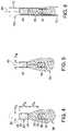
FIG. 1 , amesh 20 having afirst end 22 and asecond end 24 is provided. Themesh 20 may be disposed over afirst mandrel 90 having an outer diameter D1, such that thefirst end 22 is initially disposed proximal to thesecond end 24, as shown inFIG. 1 . - The
mesh 20 can be fashioned from absorbable or non-absorbable mesh or biologic implant. By way of example, and without limitation, the mesh material may comprise polypropylene, polyethylene, glycolide/L-lactide copolymer, PTFE, nylon, polyurethane, PEEK, PLGA, PGA, polycaprolactone, carbothane, polydioxanone, or any copolymer of the aforementioned list. - Referring to
FIG. 2 , in a next step, thefirst end 22 of themesh 20 is made to form afirst coupling element 30. In this example, thefirst coupling element 30 is in the form of afirst tube 30. However, it will be appreciated that thefirst coupling element 30 may take a form different than a tubular shape. For reference purposes below, thefirst coupling element 30 will be referenced as afirst tube 30, although it is not intended to limit the shape of thefirst coupling element 30 to tubular form. - Since the
first tube 30 is formed around thefirst mandrel 90, thefirst tube 30 comprises an inner diameter that is only slightly larger than the outer diameterD1 of thefirst mandrel 90. Further, thefirst tube 30 comprises an outer diameterDA, as shown inFIG. 2 . - The
first tube 30 is formed such that it comprises a lengthX1, as shown inFIG. 2 . In a presently preferred embodiment, the lengthX1 is less than half of the overall length of themesh 20, where the overall length is measured between the most proximal and distal endpoints of themesh 20 in a flattened state ofFIG. 1 . Preferably, the lengthX1 of thefirst tube 30 is between about 5.0 percent and about 33.0 percent of the overall length of themesh 20 in the flattened state. In this manner, the lengthX1 of thefirst tube 30 can most effectively cooperative with a subsequently formedsecond tube 40 and anintermediate portion 50, as will be explained further below. - In one exemplary technique, the
first end 22 of themesh 20 may be secured as thefirst tube 30 by melting or heat-shrinking the mesh material upon itself along thefirst end 22. In alternative embodiments, thefirst end 22 of themesh 20 may be secured as thefirst tube 30 using a separate biocompatible adhesive, one or more biocompatible sutures, or other mechanisms that can maintain the structural integrity of the tubular shape for the purposes explained below. - Referring now to
FIG. 3 , in a next step, themesh 20 may be at least partially everted by moving thesecond end 24 proximally beyond thefirst end 22. In this manner, thesecond end 24 is brought radially over and around thefirst tube 30, as shown inFIG. 3 . Therefore, in this eversion step, thesecond end 24 of themesh 20 that was originally a distal region of the device has become a proximal region. - Referring to
FIGS. 4-5 , thesecond end 24 then is made into asecond coupling element 40, for example, in a manner similar to which thefirst end 22 was made into thefirst coupling element 30. In this example, thesecond coupling element 40 is in the form of asecond tube 40. However, it will be appreciated that thesecond coupling element 40 may take a form different than a tubular shape. For example, thesecond coupling element 40 may comprise a solid inner diameter, and still may engage an inner surface of thefirst coupling element 30 using a friction fit, as explained below. For reference purposes below, thesecond coupling element 40 will be referenced as asecond tube 40, although it is not intended to limit the shape of thesecond coupling element 40 to tubular form. - In one embodiment, the
mesh 20 is disposed over asecond mandrel 92 having an outer diameterD2, as shown inFIG. 4 . Upon manufacture, thesecond tube 40 comprises an inner diameterDB, as shown inFIG. 5 , which is only slightly larger than the outer diameterD2 of thesecond mandrel 92. Like thefirst tube 30, thesecond tube 40 may be secured in the tubular manner by melting or heat-shrinking the mesh material upon itself along thesecond end 24, or alternatively, by using a separate biocompatible adhesive, one or more biocompatible sutures, or other mechanisms that can maintain the structural integrity of the tubular shape for the purposes explained below. - The outer diameterDA of the
first tube 30 is dimensioned to engage the inner diameter DB of thesecond tube 40 using a friction fit, as explained further inFIG. 7 below. To accomplish the friction fit, the outer diameterDA of thefirst tube 30 may be approximately equal to the inner diameterDB of thesecond tube 40, thereby allowing the outer diameterDA of thefirst tube 30 to snugly engage the inner diameterDB of thesecond tube 40. In the embodiment ofFIGS. 1-9 , the first andsecond tubes FIGS. 10A-10C below, various alternative configurations of the first andsecond tubes - Referring still to
FIGS. 4-5 , thesecond end 24 of themesh 20 is secured in the tubular manner such that thesecond tube 40 comprises a lengthX2. In one embodiment, the lengthX2 is less than half of the overall length of themesh 20, where (as noted above) the overall length is measured between the most proximal and distal endpoints of themesh 20 in a flattened state ofFIGS. 1-2 . Preferably, the lengthX2 of thesecond tube 40 is between about 10.0 percent and about 38.0 percent of the overall length of themesh 20 in the flattened state. - An
intermediate portion 50 of themesh 20, which is neither part of thefirst tube 30 nor thesecond tube 40, remains after formation of the first andsecond tubes intermediate portion 50 of themesh 20 may comprise the original mesh material, c.g., untreated by heat or other techniques used to form thetubes distal end 34 of thefirst tube 30 to thedistal end 44 of thesecond tube 40, as shown inFIG. 4 . - The
intermediate portion 50 of themesh 20 includes the everted portion of the mesh, as shown inFIGS. 4-5 , and may comprise between about 29.0 percent to about 85.0 percent of the overall length of themesh 20, i.e., the total length of themesh 20 minus the lengths of the first andsecond tubes intermediate portion 50 of themesh 20 may be selected based on a particular application, for example, closure of a bodily opening of a certain diameter. As will be explained further with respect toFIGS. 7-9 , theintermediate portion 50 of themesh 20 will flare radially outward to a widthw to perform its intended purpose. As will be understood, the final deployed widthw of the device is related to the overall length of theintermediate portion 50, i.e., if the length of theintermediate portion 50 is relatively large then the device can flare to a relatively large widthw, whereas if the length of theintermediate portion 50 is relatively small then the device can flare to a relatively small widthw. - Further, it is noted that an axial spacingX3 is provided between the first and
second tubes FIGS. 4-5 . The spacingX3 provides a distance for retraction of thefirst tube 30 relative to thesecond tube 40, as explained further inFIG. 7 below. By varying the spacingX3, the deployed widthw of theintermediate portion 50 may be varied accordingly. For example, if a relatively large axial spacingX3 is provided, then thefirst tube 30 must be retracted a relatively long distance before securely engaging thesecond tube 40, and during this relatively long distance theintermediate portion 50 has additional time and length to flare out to a greater widthw. - Referring to
FIGS. 5-6 , afirst tether 60 is coupled to thefirst tube 30, either on an inner or outer surface of thefirst tube 30. Thefirst tether 60 extends proximally from thefirst tube 30, is disposed through thesecond tube 40, and extends further proximally along a length of aninsertion tool 70 for actuation by a physician. A distal region of thefirst tether 60 may be coupled to thefirst tube 30 using an adhesive, mechanical member or other suitable techniques. - In a delivery state, the
mesh 20 is housed within alumen 72 of theinsertion tool 70, as shown inFIG. 6 . Theinsertion tool 70 may comprise a catheter, needle or other suitable insertion member. If a needle is used, it may be an endoscopic ultrasound (EUS) or echogenic needle, such as the EchoTip® Ultrasound Needle, or the EchoTip® Ultra Endoscopic Ultrasound Needle, both manufactured by Cook Endoscopy of Winston-Salem, N.C. - The
insertion tool 70 may be advanced to a target site using various known techniques, depending on the desired treatment modality. For example, and without limitation, in one embodiment themesh 20 may be used to treat anopening 75 of a hernia withintissue 74 of the abdominal wall, as depicted inFIG. 7 . While treatment of a hernia is explained for illustrative purposes, it will be apparent that the systems described herein may be used in a wide range of medical procedures, including but not limited to any exemplary procedures described herein. - The initial stages of the hernia repair may be performed using various techniques, for example, an open technique, a laraposcopic technique, an endoscopic technique, or a percutaneous technique. In an open technique, an incision may be made in the abdominal wall and the hernia may be repaired using generally known principles.
- In a laparoscopic technique, two or three smaller incisions may be made to access the hernia site. A laparoscope may be inserted into one incision, and surgical instruments may be inserted into the other incision(s) and the hernia may be repaired in a similar fashion as the open procedure.
- In an endoscopic technique, an endoscope is used instead of the laparoscopic devices, and no visible incisions may be made on the skin of the patient. In particular, the endoscope may be advanced through a bodily lumen such as the alimentary canal, with an access hole being created through the alimentary canal, to obtain peritoneal access to the hernia. One or more components, such as the
insertion tool 70, may be advanced through a working lumen of the endoscope. The distal end of theinsertion tool 70 may be viewed via optical elements of the endoscope, which may comprise fiber optic components for illuminating and capturing an image distal to the endoscope. - The percutaneous approach is similar to the laparoscopic approach, however, in the percutaneous approach the
insertion tool 70 may be advanced directly through a patient's abdominal skin. In particular, with the components loaded, theinsertion tool 70 is advanced directly through the abdominal skin, through thetissue 74, and may be advanced just distal to theopening 75 and into the peritoneum. In order to optimally visualize theinsertion tool 70, a laparoscopic viewing device may be positioned in the peritoneum, or an endoscope may be translumenally advanced in proximity to the target site, as noted above. Alternatively, theinsertion tool 70 and markers disposed thereon may be viewed using fluoroscopy of other suitable techniques. - After gaining access to the
opening 75 or target site using any of the above-referenced techniques, theinsertion tool 70 may be used to deliver themesh 20. Themesh 20 may be advanced within thelumen 72 of theinsertion tool 70, e.g., using a stylet, and then may be positioned such that thesecond tube 40 is aligned near thedistal end 73 of theinsertion tool 70. At this time, a majority of theintermediate portion 50 of themesh 20 may be disposed distally beyond thedistal end 73 of theinsertion tool 70. As will be appreciated, thedistal end 73 of theinsertion tool 70, and any of the first andsecond tubes - Referring to
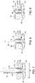
FIG. 7 , in a next step, thefirst tether 60 is retracted proximally to cause thefirst tube 30 to be retracted proximally relative to thesecond tube 40. Optionally, a stylet may be provided within thelumen 72 of theinsertion tool 70 to abut theproximal end 42 of thesecond tube 40 to hold it steady during retraction of thefirst tether 60 and coupledfirst tube 30. This causes thefirst tube 30 to engage thesecond tube 40, as depicted inFIG. 7 . - As the
first tether 60 is proximally retracted and thefirst tube 30 is retracted proximally relative to thesecond tube 40, theintermediate portion 50 of themesh 20 expands radially outward to the widthw, as depicted inFIG. 7 . Locking of the first andsecond tubes intermediate portion 50, and therefore theintermediate portion 50 is retained in its deployed state. - As explained in detail above, the first and
second tubes first tube 30 relative to thesecond tube 40. A secure engagement between the first andsecond tubes - In addition to, or in lieu of, the friction fit noted above, another locking mechanism may be used to securely hold the first and
second tubes first tube 30 may engage an interior surface of thesecond tube 40 using a one-way ratcheting mechanism, which can permit incremental sccurcmcnt to incrementally adjust the widthw of theintermediate portion 50 of themesh 20. An example of interlockingcomponents FIG. 10C below. - If the
mesh 20 is used to treat theopening 75 of a hernia withintissue 74 of the abdominal wall, theintermediate portion 50 of themesh 20 may be anchored within theopening 75 of the hernia and/or distal to theopening 75. If deployed within theopening 75, the width w of themesh 20 may be larger than an inner diameter of theopening 75 to secure themesh 20 within theopening 75 using a friction fit. Alternatively, themesh 20 may be deployed distal to theopening 75, as depicted inFIGS. 7-8 , in which case themesh 20 can assume a diameter larger than theopening 75 and provide anchoring functionality just distal to thetissue 74. - Referring to
FIGS. 8-9 , in a next step, agraft member 80 may be advanced distally over thefirst tether 60 towards themesh 20. Properties ofsuitable graft members 80 are described in detail below. Thegraft member 80 comprises afirst bore 81, which is sized to permit advancement of thegraft member 80 over thefirst tether 60. - In use, the proximal end of the
first tether 60 is disposed through thefirst bore 81 of thegraft member 80 outside of the patient, and thegraft member 80 is advanced distally relative to thefirst tether 60. Thegraft member 80 may be delivered through theinsertion tool 70. Alternatively, thegraft member 80 may be delivered directly through a trocar, e.g., a 5mm trocar. When ejected from theinsertion tool 70 or the trocar, thegraft member 80 then is positioned in place relative to thetissue 74 using a suitable grasping device, or a pusher tube or theinsertion tool 70 itself, such that thegraft member 80 is adjacent to thetissue 74 and covering theopening 75, as shown inFIG. 8 . In a next step, a suture tying device may be used to tie a knot for thefirst tether 60 to hold thegraft member 80 in place. - Optionally, a second tether (not shown) may be provided in a similar manner to the
first tether 60. In this embodiment, thegraft member 80 may comprise a second bore, whereby thefirst bore 81 of thegraft member 80 is advanced over thefirst tether 60 and the second bore of thegraft member 80 is simultaneously advanced over the second tether. In this example, a suture tying device may be used to tie the first and second tethers together in a manner that secures thegraft member 80 adjacent to thetissue 74 and themesh 20. By way of example, and without limitation, one suitable suture tying device is disclosed inU.S. Pat. No. 8,740,937 . Upon completion of the tying procedure, the one or more tethers may be cut by a suitable device, such as laparoscopic scissors, leaving themesh 20 and thegraft member 80 in place as shown inFIG. 9 . - Advantageously, using the
mesh 20, the first tether 60 (and optionally a second tether), and thegraft member 80 in combination, along with the techniques described, an enhanced mesh anchoring and graft member attachment may be achieved to comprehensively treat theopening 75. Further, the coupling of themesh 20 to thegraft member 80 provides an enhanced seal relative to a plug alone, and the secure attachment of themesh 20 to thegraft member 80 may further reduce the rate of migration of themesh 20. - The
graft member 80 may comprise any suitable material for covering theopening 75 and substantially or entirely inhibiting the protrusion of abdominal matter. In one embodiment, thegraft member 80 may comprise small intestinal submucosa (SIS), such as BIODESIGN® SURGISIS® Tissue Graft, available from Cook Biotech, Inc., West Lafayette, Indiana, which provides smart tissue remodeling through its three-dimensional extracellular matrix (ECM) that is colonized by host tissue cells and blood vessels, and provides a scaffold for connective and epithelial tissue growth and differentiation along with the ECM components. Thegraft member 80 may be lyophilized, or may comprise a vacuum pressed graft that is not lyophilized. In one example, thegraft member 80 would be a one to four layer lyophilized soft tissue graft made from any number of tissue engineered products. Reconstituted or naturally-derived collagenous materials can be used, and such materials that are at least bioresorbable will provide an advantage, with materials that are bioremodelable and promote cellular invasion and ingrowth providing particular advantage. Suitable bioremodelable materials can be provided by collagenous ECMs possessing biotropic properties, including in certain forms angiogenic collagenous extracellular matrix materials. For example, suitable collagenous materials include ECMs such as submucosa, renal capsule membrane, dermal collagen, dura mater, pericardium, fascia lata, serosa, peritoneum or basement membrane layers, including liver basement membrane. Suitable submucosa materials for these purposes include, for instance, intestinal submucosa, including small intestinal submucosa, stomach submucosa, urinary bladder submucosa, and uterine submucosa. Thegraft member 80 may also comprise a composite of a biomaterial and a biodegradeable polymer. Additional details may be found inU.S. Patent No. 6,206,931 to Cook et al . - While the exemplary embodiments herein have illustrated the use of an
expandable mesh 20 for covering anopening 75 formed in the abdominal wall, theexpandable mesh 20 disclosed herein may be useful in many other procedures. Solely by way of example, theexpandable mesh 20 may be used to treat perforations in a visceral wall, such as the stomach wall, or could be used to treat heart defects, to prevent a duodenal sleeve from migrating, for securing a graft member to tissue for reconstructing local tissue, or various other procedures that can benefit from such an expandable mesh. - Referring to
FIGS. 10A-10C , alternative embodiments are shown in which thefirst tube 30 and/or thesecond tube 40 lack constant diameters. In the embodiment ofFIG. 10A , an alternativesecond tube 40' comprises a tapered shape between proximal anddistal ends 42' and 44', wherein the distal end 44' has an inner diameter than is larger than an inner diameter of theproximal end 42'. In this embodiment ofFIG. 10A , the inner diameter of the distal end 44' of thesecond tube 40' may be larger than the outer diameter DA of thefirst tube 30 to allow thefirst tube 30 to be proximally retracted within the distal portion of thesecond tube 40, however, the inner diameter of theproximal end 42' of thesecond tube 40' may be smaller than the outer diameterDA of thefirst tube 30 so that thefirst tube 30 could not be proximally retracted beyond theproximal end 42' of thesecond tube 40'. In this manner, thefirst tube 30 may frictionally engage a region of thesecond tube 40' between the proximal anddistal ends 42' and 44'. - In a further alternative embodiment of
FIG. 10B , an alternativefirst tube 30' may comprise a tapered shape between its proximal anddistal ends 32' and 34'. A diameter at theproximal end 32' is smaller than a diameter at the distal end 34' to permit retraction into thesecond tube 40. - In the embodiment of
FIG. 10C , both first andsecond tubes 30" and 40" are tapered with proximal diameters being smaller than distal diameters. Further, in the embodiment ofFIG. 10C , an exterior surface of thefirst tube 30" may engage an interior surface of thesecond tube 40" using a one-way ratcheting mechanism using interlockingcomponents intermediate portion 50 of themesh 20. In addition to the friction fit and one-way ratcheting mechanism options, it is contemplated that other coupling methods may be used to secure the first and second tubes together, including but not limited to magnetic couplings, knobs or beads that interlock in notches, or other mechanical arrangements.
Claims (18)
- A system comprising an expandable mesh and an insertion tool for delivery of the expandable mesh to the target site, the expandable mesh comprising:a first end (22) and a second end (24);a first coupling element (30) at the first end;a second coupling element (40) at the second end; andan intermediate portion (50) disposed between the first coupling element and the second coupling element,wherein the expandable mesh is positioned, for delivery, in the insertion tool in an everted state in which the second end is positioned proximal to the first end wherein the expandable mesh is configured such that proximal retraction of the first coupling element relative to the second coupling element causes the intermediate portion to flare out to an enlarged width.
- The system of claim 1, wherein the first coupling element, the second coupling element, and the intermediate portion each originate from the same mesh material.
- The system of claim 2, wherein the intermediate portion comprises untreated mesh material, and wherein the first and second coupling elements are formed from treating the mesh material in a manner that maintains a shape of the first and second coupling elements.
- The system of claim 2, wherein at least one of the first coupling element or the second coupling element is formed by melting or heat-shrinking the mesh material.
- The system of any preceding claim wherein the first coupling element comprises a first tube and the second coupling element comprises a second tube.
- The system of claim 5, wherein the expandable mesh comprises a delivery state in which the first and second tubes lack an axial overlap, and further comprises an expanded state in which the first and second tubes at least partially axially overlap.
- The system of claim 5 or 6, wherein a distal end of the first tube transitions into a first end of the intermediate portion, and a second end of the intermediate portion transitions into a distal end of second tube.
- The system of any of claims 5 to 7, wherein the first and second tubes are dimensioned to be secured together using a friction fit when the first tube is proximally retracted relative to the second tube.
- The system of any of claims 5 to 8, wherein one of first and second tubes comprises a constant diameter along its length, while the other of the first and second tubes comprises a tapered shape.
- The system of any of claims 5 to 8, wherein both the first and second tubes comprise tapered shapes, wherein the first tube is dimensioned to be disposed at least partially within the second tube when the first tube is proximally retracted relative to the second tube.
- The system of claim 1, further comprising a first tether (60) secured to the first coupling element, wherein proximal retraction of the first tether causes proximal retraction of the first coupling element relative to the second coupling element.
- The system of any preceding claim, wherein the expandable mesh is positioned for delivery in a lumen of the insertion tool, for example wherein the insertion tool comprises a catheter or needle.
- The system of claim 12, wherein the needle comprises an echogenic needle or an endoscopic ultrasound needle.
- A method for manufacturing an expandable mesh, the method comprising:providing a mesh material (20) having a first end (22) and a second end (24);treating the mesh material (20) to form a first coupling element (30) at the first end;treating the mesh material (20) to form a second coupling element (40) at the second end, wherein an intermediate portion (50) is disposed between the first coupling element and the second coupling element,wherein the mesh material has a first state in which the first end (22) is positioned proximal to the second end (24); wherein the mesh material (20) has an everted state in which the second end (24) is positioned proximal to the first end (22); andplacing the mesh material (20) in the everted state within an insertion tool for delivery;the first coupling element (30) being configured to be proximally retracted relative to the second coupling element (40) to cause the intermediate portion (50) to flare out to an enlarged width.
- The method of claim 14, wherein at least one of the first coupling element or the second coupling element is formed by melting or heat-shrinking the mesh material.
- The method of claim 14 or 15, wherein the first coupling element comprises a first tube and/or the second coupling element comprises a second tube.
- The method of claim 16, wherein the expandable mesh comprises a delivery state in which the first and second tubes lack an axial overlap, and further comprises an expanded state in which the first and second tubes at least partially axially overlap.
- The method of claim 16, wherein a distal end of the first tube transitions into a first end of the intermediate portion, and a second end of the intermediate portion transitions into a distal end of second tube.
Priority Applications (1)
| Application Number | Priority Date | Filing Date | Title |
|---|---|---|---|
| EP22216939.3AEP4218607A1 (en) | 2014-06-30 | 2015-06-24 | Expandable mesh with locking feature |
Applications Claiming Priority (2)
| Application Number | Priority Date | Filing Date | Title |
|---|---|---|---|
| US201462018986P | 2014-06-30 | 2014-06-30 | |
| PCT/US2015/037378WO2016003722A1 (en) | 2014-06-30 | 2015-06-24 | Expandable mesh with locking feature |
Related Child Applications (1)
| Application Number | Title | Priority Date | Filing Date |
|---|---|---|---|
| EP22216939.3ADivisionEP4218607A1 (en) | 2014-06-30 | 2015-06-24 | Expandable mesh with locking feature |
Publications (2)
| Publication Number | Publication Date |
|---|---|
| EP3160362A1 EP3160362A1 (en) | 2017-05-03 |
| EP3160362B1true EP3160362B1 (en) | 2023-01-04 |
Family
ID=53511018
Family Applications (2)
| Application Number | Title | Priority Date | Filing Date |
|---|---|---|---|
| EP15734001.9AActiveEP3160362B1 (en) | 2014-06-30 | 2015-06-24 | Expandable mesh with locking feature |
| EP22216939.3APendingEP4218607A1 (en) | 2014-06-30 | 2015-06-24 | Expandable mesh with locking feature |
Family Applications After (1)
| Application Number | Title | Priority Date | Filing Date |
|---|---|---|---|
| EP22216939.3APendingEP4218607A1 (en) | 2014-06-30 | 2015-06-24 | Expandable mesh with locking feature |
Country Status (3)
| Country | Link |
|---|---|
| US (3) | US10500029B2 (en) |
| EP (2) | EP3160362B1 (en) |
| WO (1) | WO2016003722A1 (en) |
Families Citing this family (4)
| Publication number | Priority date | Publication date | Assignee | Title |
|---|---|---|---|---|
| WO2018217878A1 (en) | 2010-04-29 | 2018-11-29 | Muffin Incorporated | Closing device for tissue openings |
| US10568628B2 (en) | 2017-05-23 | 2020-02-25 | Muffin Incorporated | Closing device for tissue openings |
| US10492857B2 (en)* | 2015-08-06 | 2019-12-03 | Boston Scientific Scimed Inc | Deployment control apparatus for a catheter with a deployable array |
| US12383246B2 (en) | 2020-10-12 | 2025-08-12 | Abbott Cardiovascular Systems, Inc. | Vessel closure device with improved safety and tract hemostasis |
Family Cites Families (15)
| Publication number | Priority date | Publication date | Assignee | Title |
|---|---|---|---|---|
| US5059193A (en)* | 1989-11-20 | 1991-10-22 | Spine-Tech, Inc. | Expandable spinal implant and surgical method |
| PL331765A1 (en) | 1996-08-23 | 1999-08-02 | Cook Biotech Inc | Trnsplant prosthesis, materials and methods |
| US20100030256A1 (en)* | 1997-11-12 | 2010-02-04 | Genesis Technologies Llc | Medical Devices and Methods |
| US20020169473A1 (en)* | 1999-06-02 | 2002-11-14 | Concentric Medical, Inc. | Devices and methods for treating vascular malformations |
| US6964674B1 (en)* | 1999-09-20 | 2005-11-15 | Nuvasive, Inc. | Annulotomy closure device |
| US7993368B2 (en)* | 2003-03-13 | 2011-08-09 | C.R. Bard, Inc. | Suture clips, delivery devices and methods |
| US6712859B2 (en) | 2001-06-28 | 2004-03-30 | Ethicon, Inc. | Hernia repair prosthesis and methods for making same |
| US7892247B2 (en)* | 2001-10-03 | 2011-02-22 | Bioconnect Systems, Inc. | Devices and methods for interconnecting vessels |
| US8257394B2 (en)* | 2004-05-07 | 2012-09-04 | Usgi Medical, Inc. | Apparatus and methods for positioning and securing anchors |
| WO2007103266A2 (en)* | 2006-03-03 | 2007-09-13 | Borealis Technical Limited | Motor using magnetic normal force |
| US8740937B2 (en) | 2007-05-31 | 2014-06-03 | Cook Medical Technologies Llc | Suture lock |
| US8454632B2 (en)* | 2008-05-12 | 2013-06-04 | Xlumena, Inc. | Tissue anchor for securing tissue layers |
| WO2011137224A1 (en)* | 2010-04-29 | 2011-11-03 | Danny Azriel Sherwinter | Systems and methods for facilitating closure of bodily openings |
| US9681861B2 (en)* | 2013-03-11 | 2017-06-20 | St. Jude Medical, Cardiology Division, Inc. | Percutaneous catheter directed collapsible medical closure device |
| WO2015013666A1 (en)* | 2013-07-26 | 2015-01-29 | Cardiaq Valve Technologies, Inc. | Systems and methods for sealing openings in an anatomical wall |
- 2015
- 2015-06-24EPEP15734001.9Apatent/EP3160362B1/enactiveActive
- 2015-06-24WOPCT/US2015/037378patent/WO2016003722A1/enactiveApplication Filing
- 2015-06-24USUS14/748,992patent/US10500029B2/enactiveActive
- 2015-06-24EPEP22216939.3Apatent/EP4218607A1/enactivePending
- 2019
- 2019-11-12USUS16/680,765patent/US11771541B2/enactiveActive
- 2023
- 2023-10-02USUS18/479,456patent/US20240138970A1/enactivePending
Also Published As
| Publication number | Publication date |
|---|---|
| US20240138970A1 (en) | 2024-05-02 |
| US10500029B2 (en) | 2019-12-10 |
| US11771541B2 (en) | 2023-10-03 |
| US20200078157A1 (en) | 2020-03-12 |
| US20150374475A1 (en) | 2015-12-31 |
| EP3160362A1 (en) | 2017-05-03 |
| WO2016003722A1 (en) | 2016-01-07 |
| EP4218607A1 (en) | 2023-08-02 |
Similar Documents
| Publication | Publication Date | Title |
|---|---|---|
| US10568614B2 (en) | Systems and methods for facilitating closure of bodily openings | |
| US20240138970A1 (en) | Expandable mesh with locking feature | |
| US20180049731A1 (en) | Closing device for tissue openings | |
| AU2009324819B2 (en) | Retractable tacking device | |
| EP2600773B1 (en) | Tissue plug | |
| US8192461B2 (en) | Methods for facilitating closure of a bodily opening using one or more tacking devices | |
| EP3223717B1 (en) | Biomedical device for watertight sealing of an opening | |
| US20110245851A1 (en) | Removable medical device having at least one patch member | |
| US20100069924A1 (en) | Methods for achieving serosa-to-serosa closure of a bodily opening using one or more tacking devices | |
| AU2009239395B2 (en) | Tacking device | |
| AU2010254151B2 (en) | Tacking device and methods of deployment | |
| HK1179845A (en) | Tissue plug | |
| HK1179845B (en) | Tissue plug |
Legal Events
| Date | Code | Title | Description |
|---|---|---|---|
| STAA | Information on the status of an ep patent application or granted ep patent | Free format text:STATUS: THE INTERNATIONAL PUBLICATION HAS BEEN MADE | |
| PUAI | Public reference made under article 153(3) epc to a published international application that has entered the european phase | Free format text:ORIGINAL CODE: 0009012 | |
| STAA | Information on the status of an ep patent application or granted ep patent | Free format text:STATUS: REQUEST FOR EXAMINATION WAS MADE | |
| 17P | Request for examination filed | Effective date:20170104 | |
| AK | Designated contracting states | Kind code of ref document:A1 Designated state(s):AL AT BE BG CH CY CZ DE DK EE ES FI FR GB GR HR HU IE IS IT LI LT LU LV MC MK MT NL NO PL PT RO RS SE SI SK SM TR | |
| AX | Request for extension of the european patent | Extension state:BA ME | |
| RIN1 | Information on inventor provided before grant (corrected) | Inventor name:MCLAWHORN, TYLER, E. Inventor name:SIGMON, JOHN, C. | |
| DAV | Request for validation of the european patent (deleted) | ||
| DAX | Request for extension of the european patent (deleted) | ||
| STAA | Information on the status of an ep patent application or granted ep patent | Free format text:STATUS: EXAMINATION IS IN PROGRESS | |
| 17Q | First examination report despatched | Effective date:20180925 | |
| GRAP | Despatch of communication of intention to grant a patent | Free format text:ORIGINAL CODE: EPIDOSNIGR1 | |
| STAA | Information on the status of an ep patent application or granted ep patent | Free format text:STATUS: GRANT OF PATENT IS INTENDED | |
| INTG | Intention to grant announced | Effective date:20220223 | |
| GRAJ | Information related to disapproval of communication of intention to grant by the applicant or resumption of examination proceedings by the epo deleted | Free format text:ORIGINAL CODE: EPIDOSDIGR1 | |
| STAA | Information on the status of an ep patent application or granted ep patent | Free format text:STATUS: EXAMINATION IS IN PROGRESS | |
| GRAP | Despatch of communication of intention to grant a patent | Free format text:ORIGINAL CODE: EPIDOSNIGR1 | |
| STAA | Information on the status of an ep patent application or granted ep patent | Free format text:STATUS: GRANT OF PATENT IS INTENDED | |
| INTC | Intention to grant announced (deleted) | ||
| INTG | Intention to grant announced | Effective date:20220729 | |
| GRAS | Grant fee paid | Free format text:ORIGINAL CODE: EPIDOSNIGR3 | |
| GRAA | (expected) grant | Free format text:ORIGINAL CODE: 0009210 | |
| STAA | Information on the status of an ep patent application or granted ep patent | Free format text:STATUS: THE PATENT HAS BEEN GRANTED | |
| AK | Designated contracting states | Kind code of ref document:B1 Designated state(s):AL AT BE BG CH CY CZ DE DK EE ES FI FR GB GR HR HU IE IS IT LI LT LU LV MC MK MT NL NO PL PT RO RS SE SI SK SM TR | |
| REG | Reference to a national code | Ref country code:GB Ref legal event code:FG4D | |
| REG | Reference to a national code | Ref country code:CH Ref legal event code:EP | |
| REG | Reference to a national code | Ref country code:AT Ref legal event code:REF Ref document number:1541396 Country of ref document:AT Kind code of ref document:T Effective date:20230115 | |
| REG | Reference to a national code | Ref country code:DE Ref legal event code:R096 Ref document number:602015082168 Country of ref document:DE | |
| REG | Reference to a national code | Ref country code:IE Ref legal event code:FG4D | |
| REG | Reference to a national code | Ref country code:LT Ref legal event code:MG9D | |
| REG | Reference to a national code | Ref country code:NL Ref legal event code:MP Effective date:20230104 | |
| REG | Reference to a national code | Ref country code:AT Ref legal event code:MK05 Ref document number:1541396 Country of ref document:AT Kind code of ref document:T Effective date:20230104 | |
| PG25 | Lapsed in a contracting state [announced via postgrant information from national office to epo] | Ref country code:NL Free format text:LAPSE BECAUSE OF FAILURE TO SUBMIT A TRANSLATION OF THE DESCRIPTION OR TO PAY THE FEE WITHIN THE PRESCRIBED TIME-LIMIT Effective date:20230104 | |
| P01 | Opt-out of the competence of the unified patent court (upc) registered | Effective date:20230602 | |
| PG25 | Lapsed in a contracting state [announced via postgrant information from national office to epo] | Ref country code:RS Free format text:LAPSE BECAUSE OF FAILURE TO SUBMIT A TRANSLATION OF THE DESCRIPTION OR TO PAY THE FEE WITHIN THE PRESCRIBED TIME-LIMIT Effective date:20230104 Ref country code:PT Free format text:LAPSE BECAUSE OF FAILURE TO SUBMIT A TRANSLATION OF THE DESCRIPTION OR TO PAY THE FEE WITHIN THE PRESCRIBED TIME-LIMIT Effective date:20230504 Ref country code:NO Free format text:LAPSE BECAUSE OF FAILURE TO SUBMIT A TRANSLATION OF THE DESCRIPTION OR TO PAY THE FEE WITHIN THE PRESCRIBED TIME-LIMIT Effective date:20230404 Ref country code:LV Free format text:LAPSE BECAUSE OF FAILURE TO SUBMIT A TRANSLATION OF THE DESCRIPTION OR TO PAY THE FEE WITHIN THE PRESCRIBED TIME-LIMIT Effective date:20230104 Ref country code:LT Free format text:LAPSE BECAUSE OF FAILURE TO SUBMIT A TRANSLATION OF THE DESCRIPTION OR TO PAY THE FEE WITHIN THE PRESCRIBED TIME-LIMIT Effective date:20230104 Ref country code:HR Free format text:LAPSE BECAUSE OF FAILURE TO SUBMIT A TRANSLATION OF THE DESCRIPTION OR TO PAY THE FEE WITHIN THE PRESCRIBED TIME-LIMIT Effective date:20230104 Ref country code:ES Free format text:LAPSE BECAUSE OF FAILURE TO SUBMIT A TRANSLATION OF THE DESCRIPTION OR TO PAY THE FEE WITHIN THE PRESCRIBED TIME-LIMIT Effective date:20230104 Ref country code:AT Free format text:LAPSE BECAUSE OF FAILURE TO SUBMIT A TRANSLATION OF THE DESCRIPTION OR TO PAY THE FEE WITHIN THE PRESCRIBED TIME-LIMIT Effective date:20230104 | |
| PG25 | Lapsed in a contracting state [announced via postgrant information from national office to epo] | Ref country code:SE Free format text:LAPSE BECAUSE OF FAILURE TO SUBMIT A TRANSLATION OF THE DESCRIPTION OR TO PAY THE FEE WITHIN THE PRESCRIBED TIME-LIMIT Effective date:20230104 Ref country code:PL Free format text:LAPSE BECAUSE OF FAILURE TO SUBMIT A TRANSLATION OF THE DESCRIPTION OR TO PAY THE FEE WITHIN THE PRESCRIBED TIME-LIMIT Effective date:20230104 Ref country code:IS Free format text:LAPSE BECAUSE OF FAILURE TO SUBMIT A TRANSLATION OF THE DESCRIPTION OR TO PAY THE FEE WITHIN THE PRESCRIBED TIME-LIMIT Effective date:20230504 Ref country code:GR Free format text:LAPSE BECAUSE OF FAILURE TO SUBMIT A TRANSLATION OF THE DESCRIPTION OR TO PAY THE FEE WITHIN THE PRESCRIBED TIME-LIMIT Effective date:20230405 Ref country code:FI Free format text:LAPSE BECAUSE OF FAILURE TO SUBMIT A TRANSLATION OF THE DESCRIPTION OR TO PAY THE FEE WITHIN THE PRESCRIBED TIME-LIMIT Effective date:20230104 | |
| REG | Reference to a national code | Ref country code:DE Ref legal event code:R097 Ref document number:602015082168 Country of ref document:DE | |
| PG25 | Lapsed in a contracting state [announced via postgrant information from national office to epo] | Ref country code:SM Free format text:LAPSE BECAUSE OF FAILURE TO SUBMIT A TRANSLATION OF THE DESCRIPTION OR TO PAY THE FEE WITHIN THE PRESCRIBED TIME-LIMIT Effective date:20230104 Ref country code:RO Free format text:LAPSE BECAUSE OF FAILURE TO SUBMIT A TRANSLATION OF THE DESCRIPTION OR TO PAY THE FEE WITHIN THE PRESCRIBED TIME-LIMIT Effective date:20230104 Ref country code:EE Free format text:LAPSE BECAUSE OF FAILURE TO SUBMIT A TRANSLATION OF THE DESCRIPTION OR TO PAY THE FEE WITHIN THE PRESCRIBED TIME-LIMIT Effective date:20230104 Ref country code:DK Free format text:LAPSE BECAUSE OF FAILURE TO SUBMIT A TRANSLATION OF THE DESCRIPTION OR TO PAY THE FEE WITHIN THE PRESCRIBED TIME-LIMIT Effective date:20230104 Ref country code:CZ Free format text:LAPSE BECAUSE OF FAILURE TO SUBMIT A TRANSLATION OF THE DESCRIPTION OR TO PAY THE FEE WITHIN THE PRESCRIBED TIME-LIMIT Effective date:20230104 | |
| PLBE | No opposition filed within time limit | Free format text:ORIGINAL CODE: 0009261 | |
| STAA | Information on the status of an ep patent application or granted ep patent | Free format text:STATUS: NO OPPOSITION FILED WITHIN TIME LIMIT | |
| PG25 | Lapsed in a contracting state [announced via postgrant information from national office to epo] | Ref country code:SK Free format text:LAPSE BECAUSE OF FAILURE TO SUBMIT A TRANSLATION OF THE DESCRIPTION OR TO PAY THE FEE WITHIN THE PRESCRIBED TIME-LIMIT Effective date:20230104 | |
| 26N | No opposition filed | Effective date:20231005 | |
| PG25 | Lapsed in a contracting state [announced via postgrant information from national office to epo] | Ref country code:MC Free format text:LAPSE BECAUSE OF FAILURE TO SUBMIT A TRANSLATION OF THE DESCRIPTION OR TO PAY THE FEE WITHIN THE PRESCRIBED TIME-LIMIT Effective date:20230104 | |
| PG25 | Lapsed in a contracting state [announced via postgrant information from national office to epo] | Ref country code:SI Free format text:LAPSE BECAUSE OF FAILURE TO SUBMIT A TRANSLATION OF THE DESCRIPTION OR TO PAY THE FEE WITHIN THE PRESCRIBED TIME-LIMIT Effective date:20230104 Ref country code:MC Free format text:LAPSE BECAUSE OF FAILURE TO SUBMIT A TRANSLATION OF THE DESCRIPTION OR TO PAY THE FEE WITHIN THE PRESCRIBED TIME-LIMIT Effective date:20230104 | |
| REG | Reference to a national code | Ref country code:CH Ref legal event code:PL | |
| REG | Reference to a national code | Ref country code:BE Ref legal event code:MM Effective date:20230630 | |
| PG25 | Lapsed in a contracting state [announced via postgrant information from national office to epo] | Ref country code:LU Free format text:LAPSE BECAUSE OF NON-PAYMENT OF DUE FEES Effective date:20230624 | |
| PG25 | Lapsed in a contracting state [announced via postgrant information from national office to epo] | Ref country code:LU Free format text:LAPSE BECAUSE OF NON-PAYMENT OF DUE FEES Effective date:20230624 | |
| PG25 | Lapsed in a contracting state [announced via postgrant information from national office to epo] | Ref country code:CH Free format text:LAPSE BECAUSE OF NON-PAYMENT OF DUE FEES Effective date:20230630 | |
| PG25 | Lapsed in a contracting state [announced via postgrant information from national office to epo] | Ref country code:IT Free format text:LAPSE BECAUSE OF FAILURE TO SUBMIT A TRANSLATION OF THE DESCRIPTION OR TO PAY THE FEE WITHIN THE PRESCRIBED TIME-LIMIT Effective date:20230104 Ref country code:FR Free format text:LAPSE BECAUSE OF NON-PAYMENT OF DUE FEES Effective date:20230630 Ref country code:BE Free format text:LAPSE BECAUSE OF NON-PAYMENT OF DUE FEES Effective date:20230630 | |
| PG25 | Lapsed in a contracting state [announced via postgrant information from national office to epo] | Ref country code:BG Free format text:LAPSE BECAUSE OF FAILURE TO SUBMIT A TRANSLATION OF THE DESCRIPTION OR TO PAY THE FEE WITHIN THE PRESCRIBED TIME-LIMIT Effective date:20230104 | |
| PG25 | Lapsed in a contracting state [announced via postgrant information from national office to epo] | Ref country code:BG Free format text:LAPSE BECAUSE OF FAILURE TO SUBMIT A TRANSLATION OF THE DESCRIPTION OR TO PAY THE FEE WITHIN THE PRESCRIBED TIME-LIMIT Effective date:20230104 | |
| PGFP | Annual fee paid to national office [announced via postgrant information from national office to epo] | Ref country code:DE Payment date:20250626 Year of fee payment:11 | |
| PGFP | Annual fee paid to national office [announced via postgrant information from national office to epo] | Ref country code:GB Payment date:20250617 Year of fee payment:11 | |
| PG25 | Lapsed in a contracting state [announced via postgrant information from national office to epo] | Ref country code:CY Free format text:LAPSE BECAUSE OF FAILURE TO SUBMIT A TRANSLATION OF THE DESCRIPTION OR TO PAY THE FEE WITHIN THE PRESCRIBED TIME-LIMIT; INVALID AB INITIO Effective date:20150624 | |
| PGFP | Annual fee paid to national office [announced via postgrant information from national office to epo] | Ref country code:IE Payment date:20250617 Year of fee payment:11 | |
| PG25 | Lapsed in a contracting state [announced via postgrant information from national office to epo] | Ref country code:HU Free format text:LAPSE BECAUSE OF FAILURE TO SUBMIT A TRANSLATION OF THE DESCRIPTION OR TO PAY THE FEE WITHIN THE PRESCRIBED TIME-LIMIT; INVALID AB INITIO Effective date:20150624 |