EP3158962A1 - Preparation of micro-electrodes - Google Patents
Preparation of micro-electrodesDownload PDFInfo
- Publication number
- EP3158962A1 EP3158962A1EP16194402.0AEP16194402AEP3158962A1EP 3158962 A1EP3158962 A1EP 3158962A1EP 16194402 AEP16194402 AEP 16194402AEP 3158962 A1EP3158962 A1EP 3158962A1
- Authority
- EP
- European Patent Office
- Prior art keywords
- wire
- bead
- probe
- metal wire
- distance
- Prior art date
- Legal status (The legal status is an assumption and is not a legal conclusion. Google has not performed a legal analysis and makes no representation as to the accuracy of the status listed.)
- Granted
Links
- 238000002360preparation methodMethods0.000titledescription3
- 239000011324beadSubstances0.000claimsabstractdescription57
- 239000000523sampleSubstances0.000claimsabstractdescription44
- 238000000034methodMethods0.000claimsabstractdescription38
- 229910052751metalInorganic materials0.000claimsabstractdescription33
- 239000002184metalSubstances0.000claimsabstractdescription33
- 239000004020conductorSubstances0.000claimsabstractdescription25
- 238000001816coolingMethods0.000claimsdescription4
- 238000005498polishingMethods0.000claimsdescription4
- 230000015572biosynthetic processEffects0.000description11
- BASFCYQUMIYNBI-UHFFFAOYSA-NplatinumChemical compound[Pt]BASFCYQUMIYNBI-UHFFFAOYSA-N0.000description8
- 238000003780insertionMethods0.000description7
- 230000037431insertionEffects0.000description7
- 230000002262irrigationEffects0.000description6
- 238000003973irrigationMethods0.000description6
- 238000002679ablationMethods0.000description5
- 210000000056organAnatomy0.000description5
- 238000010348incorporationMethods0.000description4
- 229910052697platinumInorganic materials0.000description4
- 230000000712assemblyEffects0.000description3
- 238000000429assemblyMethods0.000description3
- 238000005476solderingMethods0.000description3
- RYGMFSIKBFXOCR-UHFFFAOYSA-NCopperChemical compound[Cu]RYGMFSIKBFXOCR-UHFFFAOYSA-N0.000description2
- KDLHZDBZIXYQEI-UHFFFAOYSA-NPalladiumChemical compound[Pd]KDLHZDBZIXYQEI-UHFFFAOYSA-N0.000description2
- 239000004642PolyimideSubstances0.000description2
- 239000000853adhesiveSubstances0.000description2
- 230000001070adhesive effectEffects0.000description2
- 230000000747cardiac effectEffects0.000description2
- 229910052802copperInorganic materials0.000description2
- 239000010949copperSubstances0.000description2
- 238000010586diagramMethods0.000description2
- 239000012530fluidSubstances0.000description2
- 208000014674injuryDiseases0.000description2
- 238000004519manufacturing processMethods0.000description2
- 239000004033plasticSubstances0.000description2
- 229920001721polyimidePolymers0.000description2
- 238000012545processingMethods0.000description2
- 230000008733traumaEffects0.000description2
- 238000003466weldingMethods0.000description2
- 230000004913activationEffects0.000description1
- 229910045601alloyInorganic materials0.000description1
- 239000000956alloySubstances0.000description1
- 238000009529body temperature measurementMethods0.000description1
- 210000004556brainAnatomy0.000description1
- 230000001276controlling effectEffects0.000description1
- 229910003460diamondInorganic materials0.000description1
- 239000010432diamondSubstances0.000description1
- PCHJSUWPFVWCPO-UHFFFAOYSA-NgoldChemical compound[Au]PCHJSUWPFVWCPO-UHFFFAOYSA-N0.000description1
- 229910052737goldInorganic materials0.000description1
- 239000010931goldSubstances0.000description1
- 238000002847impedance measurementMethods0.000description1
- 229910052741iridiumInorganic materials0.000description1
- GKOZUEZYRPOHIO-UHFFFAOYSA-Niridium atomChemical compound[Ir]GKOZUEZYRPOHIO-UHFFFAOYSA-N0.000description1
- 150000002739metalsChemical class0.000description1
- 238000012986modificationMethods0.000description1
- 230000004048modificationEffects0.000description1
- 230000003287optical effectEffects0.000description1
- 229910052763palladiumInorganic materials0.000description1
- 230000001105regulatory effectEffects0.000description1
- 229910000679solderInorganic materials0.000description1
Images


Classifications
- A—HUMAN NECESSITIES
- A61—MEDICAL OR VETERINARY SCIENCE; HYGIENE
- A61B—DIAGNOSIS; SURGERY; IDENTIFICATION
- A61B5/00—Measuring for diagnostic purposes; Identification of persons
- A61B5/24—Detecting, measuring or recording bioelectric or biomagnetic signals of the body or parts thereof
- A61B5/25—Bioelectric electrodes therefor
- A61B5/279—Bioelectric electrodes therefor specially adapted for particular uses
- A61B5/28—Bioelectric electrodes therefor specially adapted for particular uses for electrocardiography [ECG]
- A61B5/283—Invasive
- A61B5/287—Holders for multiple electrodes, e.g. electrode catheters for electrophysiological study [EPS]
- B—PERFORMING OPERATIONS; TRANSPORTING
- B23—MACHINE TOOLS; METAL-WORKING NOT OTHERWISE PROVIDED FOR
- B23H—WORKING OF METAL BY THE ACTION OF A HIGH CONCENTRATION OF ELECTRIC CURRENT ON A WORKPIECE USING AN ELECTRODE WHICH TAKES THE PLACE OF A TOOL; SUCH WORKING COMBINED WITH OTHER FORMS OF WORKING OF METAL
- B23H1/00—Electrical discharge machining, i.e. removing metal with a series of rapidly recurring electrical discharges between an electrode and a workpiece in the presence of a fluid dielectric
- B23H1/04—Electrodes specially adapted therefor or their manufacture
- A—HUMAN NECESSITIES
- A61—MEDICAL OR VETERINARY SCIENCE; HYGIENE
- A61B—DIAGNOSIS; SURGERY; IDENTIFICATION
- A61B18/00—Surgical instruments, devices or methods for transferring non-mechanical forms of energy to or from the body
- A61B18/04—Surgical instruments, devices or methods for transferring non-mechanical forms of energy to or from the body by heating
- A61B18/08—Surgical instruments, devices or methods for transferring non-mechanical forms of energy to or from the body by heating by means of electrically-heated probes
- A61B18/082—Probes or electrodes therefor
- A—HUMAN NECESSITIES
- A61—MEDICAL OR VETERINARY SCIENCE; HYGIENE
- A61B—DIAGNOSIS; SURGERY; IDENTIFICATION
- A61B18/00—Surgical instruments, devices or methods for transferring non-mechanical forms of energy to or from the body
- A61B18/04—Surgical instruments, devices or methods for transferring non-mechanical forms of energy to or from the body by heating
- A61B18/12—Surgical instruments, devices or methods for transferring non-mechanical forms of energy to or from the body by heating by passing a current through the tissue to be heated, e.g. high-frequency current
- A61B18/14—Probes or electrodes therefor
- A61B18/1492—Probes or electrodes therefor having a flexible, catheter-like structure, e.g. for heart ablation
- A—HUMAN NECESSITIES
- A61—MEDICAL OR VETERINARY SCIENCE; HYGIENE
- A61B—DIAGNOSIS; SURGERY; IDENTIFICATION
- A61B5/00—Measuring for diagnostic purposes; Identification of persons
- A61B5/24—Detecting, measuring or recording bioelectric or biomagnetic signals of the body or parts thereof
- A61B5/25—Bioelectric electrodes therefor
- A61B5/279—Bioelectric electrodes therefor specially adapted for particular uses
- A61B5/28—Bioelectric electrodes therefor specially adapted for particular uses for electrocardiography [ECG]
- A61B5/283—Invasive
- A—HUMAN NECESSITIES
- A61—MEDICAL OR VETERINARY SCIENCE; HYGIENE
- A61B—DIAGNOSIS; SURGERY; IDENTIFICATION
- A61B5/00—Measuring for diagnostic purposes; Identification of persons
- A61B5/24—Detecting, measuring or recording bioelectric or biomagnetic signals of the body or parts thereof
- A61B5/25—Bioelectric electrodes therefor
- A61B5/279—Bioelectric electrodes therefor specially adapted for particular uses
- A61B5/291—Bioelectric electrodes therefor specially adapted for particular uses for electroencephalography [EEG]
- A—HUMAN NECESSITIES
- A61—MEDICAL OR VETERINARY SCIENCE; HYGIENE
- A61B—DIAGNOSIS; SURGERY; IDENTIFICATION
- A61B5/00—Measuring for diagnostic purposes; Identification of persons
- A61B5/24—Detecting, measuring or recording bioelectric or biomagnetic signals of the body or parts thereof
- A61B5/316—Modalities, i.e. specific diagnostic methods
- A61B5/318—Heart-related electrical modalities, e.g. electrocardiography [ECG]
- A61B5/339—Displays specially adapted therefor
- A—HUMAN NECESSITIES
- A61—MEDICAL OR VETERINARY SCIENCE; HYGIENE
- A61B—DIAGNOSIS; SURGERY; IDENTIFICATION
- A61B5/00—Measuring for diagnostic purposes; Identification of persons
- A61B5/68—Arrangements of detecting, measuring or recording means, e.g. sensors, in relation to patient
- A61B5/6846—Arrangements of detecting, measuring or recording means, e.g. sensors, in relation to patient specially adapted to be brought in contact with an internal body part, i.e. invasive
- A61B5/6847—Arrangements of detecting, measuring or recording means, e.g. sensors, in relation to patient specially adapted to be brought in contact with an internal body part, i.e. invasive mounted on an invasive device
- A61B5/6852—Catheters
- A—HUMAN NECESSITIES
- A61—MEDICAL OR VETERINARY SCIENCE; HYGIENE
- A61B—DIAGNOSIS; SURGERY; IDENTIFICATION
- A61B5/00—Measuring for diagnostic purposes; Identification of persons
- A61B5/68—Arrangements of detecting, measuring or recording means, e.g. sensors, in relation to patient
- A61B5/6846—Arrangements of detecting, measuring or recording means, e.g. sensors, in relation to patient specially adapted to be brought in contact with an internal body part, i.e. invasive
- A61B5/6867—Arrangements of detecting, measuring or recording means, e.g. sensors, in relation to patient specially adapted to be brought in contact with an internal body part, i.e. invasive specially adapted to be attached or implanted in a specific body part
- A61B5/6869—Heart
- A—HUMAN NECESSITIES
- A61—MEDICAL OR VETERINARY SCIENCE; HYGIENE
- A61N—ELECTROTHERAPY; MAGNETOTHERAPY; RADIATION THERAPY; ULTRASOUND THERAPY
- A61N1/00—Electrotherapy; Circuits therefor
- A61N1/02—Details
- A61N1/04—Electrodes
- A61N1/05—Electrodes for implantation or insertion into the body, e.g. heart electrode
- A61N1/0526—Head electrodes
- A61N1/0529—Electrodes for brain stimulation
- A—HUMAN NECESSITIES
- A61—MEDICAL OR VETERINARY SCIENCE; HYGIENE
- A61N—ELECTROTHERAPY; MAGNETOTHERAPY; RADIATION THERAPY; ULTRASOUND THERAPY
- A61N1/00—Electrotherapy; Circuits therefor
- A61N1/02—Details
- A61N1/04—Electrodes
- A61N1/05—Electrodes for implantation or insertion into the body, e.g. heart electrode
- A61N1/056—Transvascular endocardial electrode systems
- A61N1/0565—Electrode heads
- B—PERFORMING OPERATIONS; TRANSPORTING
- B81—MICROSTRUCTURAL TECHNOLOGY
- B81B—MICROSTRUCTURAL DEVICES OR SYSTEMS, e.g. MICROMECHANICAL DEVICES
- B81B1/00—Devices without movable or flexible elements, e.g. microcapillary devices
- B—PERFORMING OPERATIONS; TRANSPORTING
- B81—MICROSTRUCTURAL TECHNOLOGY
- B81B—MICROSTRUCTURAL DEVICES OR SYSTEMS, e.g. MICROMECHANICAL DEVICES
- B81B7/00—Microstructural systems; Auxiliary parts of microstructural devices or systems
- A—HUMAN NECESSITIES
- A61—MEDICAL OR VETERINARY SCIENCE; HYGIENE
- A61B—DIAGNOSIS; SURGERY; IDENTIFICATION
- A61B18/00—Surgical instruments, devices or methods for transferring non-mechanical forms of energy to or from the body
- A61B18/04—Surgical instruments, devices or methods for transferring non-mechanical forms of energy to or from the body by heating
- A61B18/12—Surgical instruments, devices or methods for transferring non-mechanical forms of energy to or from the body by heating by passing a current through the tissue to be heated, e.g. high-frequency current
- A61B18/14—Probes or electrodes therefor
- A—HUMAN NECESSITIES
- A61—MEDICAL OR VETERINARY SCIENCE; HYGIENE
- A61B—DIAGNOSIS; SURGERY; IDENTIFICATION
- A61B18/00—Surgical instruments, devices or methods for transferring non-mechanical forms of energy to or from the body
- A61B2018/00005—Cooling or heating of the probe or tissue immediately surrounding the probe
- A61B2018/00011—Cooling or heating of the probe or tissue immediately surrounding the probe with fluids
- A61B2018/00017—Cooling or heating of the probe or tissue immediately surrounding the probe with fluids with gas
- A—HUMAN NECESSITIES
- A61—MEDICAL OR VETERINARY SCIENCE; HYGIENE
- A61B—DIAGNOSIS; SURGERY; IDENTIFICATION
- A61B18/00—Surgical instruments, devices or methods for transferring non-mechanical forms of energy to or from the body
- A61B2018/00053—Mechanical features of the instrument of device
- A61B2018/00059—Material properties
- A61B2018/00071—Electrical conductivity
- A61B2018/00083—Electrical conductivity low, i.e. electrically insulating
- A—HUMAN NECESSITIES
- A61—MEDICAL OR VETERINARY SCIENCE; HYGIENE
- A61B—DIAGNOSIS; SURGERY; IDENTIFICATION
- A61B18/00—Surgical instruments, devices or methods for transferring non-mechanical forms of energy to or from the body
- A61B2018/00315—Surgical instruments, devices or methods for transferring non-mechanical forms of energy to or from the body for treatment of particular body parts
- A61B2018/00345—Vascular system
- A61B2018/00351—Heart
- A—HUMAN NECESSITIES
- A61—MEDICAL OR VETERINARY SCIENCE; HYGIENE
- A61B—DIAGNOSIS; SURGERY; IDENTIFICATION
- A61B18/00—Surgical instruments, devices or methods for transferring non-mechanical forms of energy to or from the body
- A61B2018/00571—Surgical instruments, devices or methods for transferring non-mechanical forms of energy to or from the body for achieving a particular surgical effect
- A61B2018/00577—Ablation
- A—HUMAN NECESSITIES
- A61—MEDICAL OR VETERINARY SCIENCE; HYGIENE
- A61B—DIAGNOSIS; SURGERY; IDENTIFICATION
- A61B18/00—Surgical instruments, devices or methods for transferring non-mechanical forms of energy to or from the body
- A61B2018/00571—Surgical instruments, devices or methods for transferring non-mechanical forms of energy to or from the body for achieving a particular surgical effect
- A61B2018/00595—Cauterization
- A—HUMAN NECESSITIES
- A61—MEDICAL OR VETERINARY SCIENCE; HYGIENE
- A61B—DIAGNOSIS; SURGERY; IDENTIFICATION
- A61B18/00—Surgical instruments, devices or methods for transferring non-mechanical forms of energy to or from the body
- A61B2018/00964—Features of probes
- A—HUMAN NECESSITIES
- A61—MEDICAL OR VETERINARY SCIENCE; HYGIENE
- A61B—DIAGNOSIS; SURGERY; IDENTIFICATION
- A61B18/00—Surgical instruments, devices or methods for transferring non-mechanical forms of energy to or from the body
- A61B18/04—Surgical instruments, devices or methods for transferring non-mechanical forms of energy to or from the body by heating
- A61B18/12—Surgical instruments, devices or methods for transferring non-mechanical forms of energy to or from the body by heating by passing a current through the tissue to be heated, e.g. high-frequency current
- A61B18/14—Probes or electrodes therefor
- A61B2018/1405—Electrodes having a specific shape
- A61B2018/1417—Ball
- A—HUMAN NECESSITIES
- A61—MEDICAL OR VETERINARY SCIENCE; HYGIENE
- A61B—DIAGNOSIS; SURGERY; IDENTIFICATION
- A61B18/00—Surgical instruments, devices or methods for transferring non-mechanical forms of energy to or from the body
- A61B18/04—Surgical instruments, devices or methods for transferring non-mechanical forms of energy to or from the body by heating
- A61B18/12—Surgical instruments, devices or methods for transferring non-mechanical forms of energy to or from the body by heating by passing a current through the tissue to be heated, e.g. high-frequency current
- A61B18/14—Probes or electrodes therefor
- A61B2018/1467—Probes or electrodes therefor using more than two electrodes on a single probe
- A—HUMAN NECESSITIES
- A61—MEDICAL OR VETERINARY SCIENCE; HYGIENE
- A61B—DIAGNOSIS; SURGERY; IDENTIFICATION
- A61B2218/00—Details of surgical instruments, devices or methods for transferring non-mechanical forms of energy to or from the body
- A61B2218/001—Details of surgical instruments, devices or methods for transferring non-mechanical forms of energy to or from the body having means for irrigation and/or aspiration of substances to and/or from the surgical site
- A61B2218/002—Irrigation
- A—HUMAN NECESSITIES
- A61—MEDICAL OR VETERINARY SCIENCE; HYGIENE
- A61B—DIAGNOSIS; SURGERY; IDENTIFICATION
- A61B2562/00—Details of sensors; Constructional details of sensor housings or probes; Accessories for sensors
- A61B2562/02—Details of sensors specially adapted for in-vivo measurements
- A61B2562/0209—Special features of electrodes classified in A61B5/24, A61B5/25, A61B5/283, A61B5/291, A61B5/296, A61B5/053
- A—HUMAN NECESSITIES
- A61—MEDICAL OR VETERINARY SCIENCE; HYGIENE
- A61B—DIAGNOSIS; SURGERY; IDENTIFICATION
- A61B2562/00—Details of sensors; Constructional details of sensor housings or probes; Accessories for sensors
- A61B2562/12—Manufacturing methods specially adapted for producing sensors for in-vivo measurements
- A61B2562/125—Manufacturing methods specially adapted for producing sensors for in-vivo measurements characterised by the manufacture of electrodes
- Y—GENERAL TAGGING OF NEW TECHNOLOGICAL DEVELOPMENTS; GENERAL TAGGING OF CROSS-SECTIONAL TECHNOLOGIES SPANNING OVER SEVERAL SECTIONS OF THE IPC; TECHNICAL SUBJECTS COVERED BY FORMER USPC CROSS-REFERENCE ART COLLECTIONS [XRACs] AND DIGESTS
- Y10—TECHNICAL SUBJECTS COVERED BY FORMER USPC
- Y10T—TECHNICAL SUBJECTS COVERED BY FORMER US CLASSIFICATION
- Y10T29/00—Metal working
- Y10T29/49—Method of mechanical manufacture
- Y10T29/49002—Electrical device making
- Y10T29/49117—Conductor or circuit manufacturing
- Y10T29/49174—Assembling terminal to elongated conductor
Definitions
- the present inventionrelates generally to electrode preparation, and specifically to preparation of extremely small electrodes.
- Invasive medical probes or catheters used for cardiac procedurestypically use electrodes in order to acquire potentials of a region of the heart being investigated or being operated on.
- the electrodesmay also be used to inject current into the heart, for example for ablation, pacing, or for determining a location of the probe.
- the probeIn order to minimize trauma to the patient involved, the probe typically has a diameter that is as small as possible,
- the small size of the probesconsequently means that the electrodes of the probes have a correspondingly extremely small size. Furthermore, in some cases it is desirable that one probe should have a number of electrodes that are spatially separated and electrically insulated from each other. Such multiple electrode probes can be used for simultaneous potential acquisition from, and/or simultaneous ablation of, spatially separated sites in the heart. However, the multiple electrodes of necessity have to be of an extremely small size.
- ElectrodesOther types of procedures using electrodes, such as electroencephalographic procedures, also benefit from using small probes with extremely small electrodes, so as to minimize trauma to patients.
- Japanese Patent Publication JP2000-235995to Kyomasu Ryuichi , whose disclosure is incorporated herein by reference, describes a ball forming method for wire bonding.
- the disclosurestates that a high voltage is applied between the tip of a wire extending from the bottom of a capillary and a discharge electrode, forming a ball at the tip of the wire.
- An embodiment of the present inventionprovides a method, including:
- the metal wirehas another end
- the methodincludes attaching a further metal wire to the other end to make an electrical contact
- assembling the wireincludes assembling the wire with the created bead and the attached further metal wire into the invasive probe.
- the methodmay further include sliding then shrinking shrink sleeving over the created bead, the metal wire, the electrical contact, and the further metal wire.
- the methodincludes sliding an electrically insulating sleeve over a portion of the wire not including the bead.
- the methodincludes sliding the sleeve to butt against the bead.
- the methodmay also include assembling the wire with the created bead and the electrically insulating sleeve into the invasive probe.
- the conductorincludes a further wire, and the distance includes the distance from an end of the further wire to the end of the metal wire.
- the further wire and the metal wireare aligned collinearly.
- the distanceis 0.1 mm or less.
- the beadhas a spherical bead-surface.
- the spherical bead-surfacemay be flush with the outer surface of the probe.
- the spherical bead-surfaceprotrudes from the outer surface of the probe by a radius of the spherical bead-surface.
- the methodmay include polishing the spherical bead-surface to be flush with the outer surface of the probe.
- the spherical bead-surfaceis recessed into the outer surface of the probe by a radius of the spherical bead-surface.
- the methodincludes providing natural air cooling to the conductor and the end during the electrical discharge.
- apparatusincluding:
- Micro-electrodes on the distal end of an invasive probetypically have an extremely small diameter, in some cases of about 400 microns.
- the micro-electrodesare typically of an inert metal such as platinum, gold, palladium, iridium, or an alloy formed from these metals, and to form the micro-electrodes a prior art system attaches, by soldering, an extremely small platinum bead to a conducting wire that is already in the distal end. The attachment can be tedious and time consuming, as well as requiring specialized equipment that can manipulate and solder extremely small entities.
- a first end of a short metal wiretypically made of an inert metal such as platinum, is positioned at a distance from a conductor.
- the conductoris typically also in the form of a wire, and is herein also termed a "spark" wire.
- An electrical discharge, or sparkis created between the spark wire and the first end of the inert metal wire, while setting the distance and an electrical potential of the discharge, between the spark wire and the first end, so as to create a bead of a predefined size on the first end of the inert metal wire.
- the inert wire with its beadis assembled into an invasive probe, so that the bead is positioned at an outer surface of the probe.
- the second end of the short metal wireis attached to a conducting wire, typically of copper.
- An electrically insulating plastic sleevesuch as a polyimide sleeve, may be slid over the combination, after which the bead may be formed on the first end of the short metal wire as described above.
- the sleeved combination, with its created bead,may then be inserted into an aperture of the probe, a diameter of the aperture being set to correspond with an external diameter of the sleeve.
- the insertiontypically causes the sleeve to butt against the bead so that after insertion the bead, which acts as a micro-electrode, is insulated from the probe, and so that the sleeved combination acts to seal the aperture.
- a bead of a given sizemay be easily produced by setting specific values for the distance and electrical potential referred to above. Furthermore, the method of production of the bead eliminates the necessity of soldering the bead, as is required in prior art methods of micro-electrode assembly.
- Fig. 1is a schematic illustration of a catheterization system 20, according to an embodiment of the present invention.
- System 20is typically used during a medical procedure on a body organ, the procedure, inter alia , being assumed to acquire electrical signals from the organ, and/or to inject electrical signals to the organ.
- the body organby way of example, is assumed to comprise the heart, wherein the system is applied to acquire intra-cardiac electrocardiogram (ECG) signals from the heart.
- ECGintra-cardiac electrocardiogram
- system 20may be applied to acquire and/or inject substantially any electrical signals from/to any body organ, such as acquiring electroencephalograph (EEG) signals from the brain.
- EEGelectroencephalograph
- system 20senses intra-cardiac ECG signals from a heart 22, using a probe 24.
- a distal end 26 of the probeis assumed to have at least one micro-electrode assembly 28 for sensing the signals.
- the structure and formation of assembly 28is described in more detail below, as is the incorporation of the assembly into distal end 26.
- probe 24comprises a catheter which is inserted into the body of a subject 30 during a cardiac procedure performed by a user 32 of system 20.
- user 32is assumed to be a medical professional.
- System 20may be controlled by a system processor 40, comprising a processing unit 42 communicating with an ECG module 44.
- Processor 40may be mounted in a console 50, which comprises operating controls 52 that typically include a pointing device such as a mouse or trackball.
- Professional 32uses the operating controls to interact with the processor, which, as described below, may be used to present results produced by system 20 to the professional on a screen 54.
- the screendisplays results of analysis and processing of ECG signals acquired by one or more electrodes within assembly 28, after the signals have been transferred to ECG module 44.
- the resultant ECG signalsare presented on screen 54 in the form of a potential vs. time graph, and a schematic example 60 of such a graph is illustrated in Fig. 1 .
- the resultant ECG signals, obtained from the ECG modulemay also be used by processor 40 to derive other results associated with the ECG signals, such as a local activation time (LAT).
- LATlocal activation time
- Processor 40uses software stored in a memory of the processor to operate system 20.
- the softwaremay be downloaded to processor 40 in electronic form, over a network, for example, or it may, alternatively or additionally, be provided and/or stored on non-transitory tangible media, such as magnetic, optical, or electronic memory.
- Processor 40typically comprises other modules apart from ECG module 44, such as a probe tracking module, a force module that measures a force on distal end 26, an irrigation module controlling irrigation fluid for the distal end, and an ablation module that provides regulated power to the distal end.
- ECG module 44such as a probe tracking module, a force module that measures a force on distal end 26, an irrigation module controlling irrigation fluid for the distal end, and an ablation module that provides regulated power to the distal end.
- a probe tracking modulesuch as a probe tracking module that measures a force on distal end 26
- an irrigation module controlling irrigation fluid for the distal endsuch as an irrigation module controlling irrigation fluid for the distal end
- an ablation modulethat provides regulated power to the distal end.
- Such modulesare not shown in Fig. 1 .
- Fig. 2is a schematic diagram illustrating a portion of distal end 26 in cross-section, according to an embodiment of the present invention.
- Distal end 26is assumed, by way of example, to be formed of a conductive dome 70, into which irrigation apertures 72 and assembly apertures 74 have been formed.
- three irrigation apertures 72are shown in Fig. 2 , but typically there are many more than three such apertures, and the irrigation apertures may be formed in substantially any part of dome 70.
- three assembly apertures 74are shown in Fig.
- Dome 70may be generally similar in structure to the dome described in U.S. Patent Application 2013/0060245 referenced above.
- Dome 70has an outer surface 88 and an inner surface 90, the latter forming an outer surface of a cavity 82 enclosed by the dome.
- Cavity 82may be configured to receive irrigation fluid that is expelled via apertures 72.
- assemblies 28are inserted into respected assembly apertures 74 so that respective proximal portions 84 of the assemblies enter and traverse cavity 82, while respective distal portions 86 of the assemblies are at outer surface 88 of dome 70.
- a micro-electrode 92 in distal portion 86may protrude slightly from outer surface 88, as exemplified in Fig. 2 for assembly 28 in assembly aperture 74 of edge 80.
- micro-electrode 92 in distal portion 86may be recessed slightly with respect to outer surface 88, as exemplified in the figure for assembly 28 in assembly aperture 74 of end 78.
- the micro-electrode in distal portion 86may be approximately flush with outer surface 88, as exemplified in the figure for assembly 28 in assembly aperture 74 of wall 81.
- a secondary polishing stepmay be performed to contour the bead so that it exactly matches the exterior surface geometry.
- micro-electrode 92protrudes from, is flush with, or is recessed into surface 88, after insertion of a given assembly 28 within its respective aperture the micro-electrode is able to receive and transmit electrical signals from tissue when dome 70 contacts the tissue.
- micro-electrode 92The formation of micro-electrode 92 is described below.
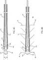
- Figs. 3A - 3Fillustrate stages in the formation of assembly 28, and Fig. 4 is a flowchart of steps in the formation of the assembly and incorporation of the assembly into distal end 26, according to an embodiment of the present invention.
- a metallic biocompatible inert conductive wire 150herein assumed to comprise platinum, is attached, typically by soldering, resistance welding, or laser welding, to another conductor 152 in the form of a wire, typically copper.
- Inert metal wire 150has a distal end 154 and a proximal end 156.
- Conductor 152has a distal end 158 and a proximal end 160.
- Step 100is illustrated schematically in Fig. 3A , and in an embodiment of the present invention, inert wire 150 has an approximate length of 3 mm and an approximate diameter of 175 microns. Typically, although not necessarily, conductor 152 has a diameter smaller than the diameter of inert conductive wire 150.
- step 104the combination formed in step 102 is mounted in a fixed position, typically by being gripped in a vice.
- a pointed tip 174 of a conductor 176is positioned a measured distance "A" from inert wire distal end 154. In some embodiments distance "A" is approximately 0.1 mm or less. Typically, the two wires should be collinear, but may be in any convenient orientation, for example horizontal or vertical.
- Conductor 176is also referred to herein as spark wire 176.
- An electrical generator 180is connected between spark wire 176 and conductor 152.
- generator 180comprises a resistance welder, such as a Miyachi Unitek model UB29 resistance welder produced by Amada Miyachi of Monrovia, CA, which provides a high DC current.
- a voltage level of generator 180is adjusted so that when activated, the generator forms an electric discharge, in air, also herein referred to as a spark, between tip 174 and inert wire distal end 154.
- the generatoris activated, typically at a voltage of approximately 1 V and for a duration of approximately 5 ms, during which approximately 200 A of DC current flows, so as to cause the electric discharge.
- the dischargedeforms distal end 154 into micro-electrode 92, which is in the form of a bead that is typically partly spherical in shape and that remains attached to inert wire 150.
- the sparkwas generated with the generator set to provide at least 100 amps for between 1 and 10 ms.
- Micro-electrode 92is also referred to herein as bead 92. Formation of bead 92 concludes the process of forming assembly 28, prior to its insertion into distal end 26 of probe 24.
- Fig. 3Bschematically illustrates steps 102 - 108 up to the formation of bead 92
- Fig. 3Cschematically illustrates completed micro-electrode assembly 28 after formation of bead 92.
- Bead 92has a diameter D, which is greater than the diameter of inert wire 150. In some embodiments diameter D is approximately 400 microns.
- an insulating sleeve 170typically of a plastic such as a polyimide, is slid over the inert wire-conductor combination formed in step 100.
- An initial internal diameter of sleeve 170 in an unexpanded formis configured to be slightly less than the diameter of inert wire 150. The operation of sliding is implemented so that sleeve 170 expands and grips inert wire 150, i.e., so that the internal diameter of the sleeve in its expanded form, at the region of inert wire 150, equals the diameter of the inert wire.
- thin-wall shrink sleevingcan be used over the combination.
- the sleevingconforms to the bead, the inert wire, and the conductive wire, serving to electrically isolate the combination.
- a final fabrication step 110completed micro-electrode assembly 28, produced in step 109, is slid into a selected assembly aperture 74 in dome 70.
- the apertureis configured to have a diameter that accommodates the diameter of the insulating sleeve, but not that of the bead. After the micro-assembly is seated in the selected assembly aperture, it is then secured using adhesive.
- any given assembly 28 into a respective assembly aperture 74concludes with bead 92 slightly protruding from outer surface 88, being approximately flush with the surface, or being slightly recessed into the surface.
- Figs. 3D , 3E, and 3Fschematically illustrate step 110, after assembly 28 has been inserted into aperture 74, so that bead 92 respectively protrudes from outer surface 88, is approximately flush with the surface, and is slightly recessed into the surface.
- a typical protrusion distanceis the radius of the bead, so that a 400 micron bead may protrude by 200 microns from the surface.
- a typical recess distanceis approximately the same as the typical protrusion distance.
- any protrusion of the micro-electrodecan be eliminated by polishing the surface of dome 70, e.g., by buffing, after the assembly has been secured with adhesive.
Landscapes
- Health & Medical Sciences (AREA)
- Life Sciences & Earth Sciences (AREA)
- Engineering & Computer Science (AREA)
- Heart & Thoracic Surgery (AREA)
- Veterinary Medicine (AREA)
- Biomedical Technology (AREA)
- Animal Behavior & Ethology (AREA)
- General Health & Medical Sciences (AREA)
- Public Health (AREA)
- Surgery (AREA)
- Molecular Biology (AREA)
- Medical Informatics (AREA)
- Physics & Mathematics (AREA)
- Cardiology (AREA)
- Pathology (AREA)
- Biophysics (AREA)
- Nuclear Medicine, Radiotherapy & Molecular Imaging (AREA)
- Radiology & Medical Imaging (AREA)
- Otolaryngology (AREA)
- Plasma & Fusion (AREA)
- Psychology (AREA)
- Neurosurgery (AREA)
- Neurology (AREA)
- Vascular Medicine (AREA)
- Manufacturing & Machinery (AREA)
- Mechanical Engineering (AREA)
- Computer Hardware Design (AREA)
- Microelectronics & Electronic Packaging (AREA)
- Physiology (AREA)
- Surgical Instruments (AREA)
- Measurement And Recording Of Electrical Phenomena And Electrical Characteristics Of The Living Body (AREA)
Abstract
Description
- The present invention relates generally to electrode preparation, and specifically to preparation of extremely small electrodes.
- Invasive medical probes or catheters used for cardiac procedures typically use electrodes in order to acquire potentials of a region of the heart being investigated or being operated on. The electrodes may also be used to inject current into the heart, for example for ablation, pacing, or for determining a location of the probe. In order to minimize trauma to the patient involved, the probe typically has a diameter that is as small as possible,
- The small size of the probes consequently means that the electrodes of the probes have a correspondingly extremely small size. Furthermore, in some cases it is desirable that one probe should have a number of electrodes that are spatially separated and electrically insulated from each other. Such multiple electrode probes can be used for simultaneous potential acquisition from, and/or simultaneous ablation of, spatially separated sites in the heart. However, the multiple electrodes of necessity have to be of an extremely small size.
- Other types of procedures using electrodes, such as electroencephalographic procedures, also benefit from using small probes with extremely small electrodes, so as to minimize trauma to patients.
U. S. Patent Application 2013/0060245, to Grunewald et al. , whose disclosure is incorporated herein by reference, describes an ablation catheter adapted for direct tissue contact. The catheter is stated to have micro-elements that provide more accurate sensing of tissue, including thermal and electrical properties for temperature and impedance measurements. The micro-elements extend through a hollow chamber of an irrigated ablation electrode, and distal ends of the micro-elements can protrude outside of the electrode or be flush with the electrode.- Japanese Patent Publication
JP2000-235995, to Kyomasu Ryuichi - Documents incorporated by reference in the present patent application are to be considered an integral part of the application except that, to the extent that any terms are defined in these incorporated documents in a manner that conflicts with definitions made explicitly or implicitly in the present specification, only the definitions in the present specification should be considered.
- An embodiment of the present invention provides a method, including:
- providing a metal wire having a wire diameter and an end;
- positioning a conductor at a distance from the end of the wire;
- creating an electrical discharge between the conductor and the end, while setting the distance and an electrical potential of the discharge, so as to create a bead of a predefined size on the end; and
- assembling the wire with the created bead into an invasive probe, so that the bead is positioned at an outer surface of the probe.
- Typically, the metal wire has another end, and the method includes attaching a further metal wire to the other end to make an electrical contact, and assembling the wire includes assembling the wire with the created bead and the attached further metal wire into the invasive probe. The method may further include sliding then shrinking shrink sleeving over the created bead, the metal wire, the electrical contact, and the further metal wire.
- In a disclosed embodiment the method includes sliding an electrically insulating sleeve over a portion of the wire not including the bead. Typically, the method includes sliding the sleeve to butt against the bead. The method may also include assembling the wire with the created bead and the electrically insulating sleeve into the invasive probe.
- In a further disclosed embodiment the conductor includes a further wire, and the distance includes the distance from an end of the further wire to the end of the metal wire. Typically, the further wire and the metal wire are aligned collinearly.
- In a yet further disclosed embodiment the distance is 0.1 mm or less.
- In an alternative embodiment, the bead has a spherical bead-surface. The spherical bead-surface may be flush with the outer surface of the probe. Alternatively, the spherical bead-surface protrudes from the outer surface of the probe by a radius of the spherical bead-surface. The method may include polishing the spherical bead-surface to be flush with the outer surface of the probe. Further alternatively, the spherical bead-surface is recessed into the outer surface of the probe by a radius of the spherical bead-surface.
- In a further alternative embodiment the method includes providing natural air cooling to the conductor and the end during the electrical discharge.
- There is further provided, according to an embodiment of the present invention, apparatus, including:
- a metal wire having a wire diameter and an end;
- a conductor, positioned at a distance from the end of the wire;
- a bead of a predefined size formed on the end by creating an electrical discharge between the conductor and the end, while setting the distance and an electrical potential of the discharge; and
- an invasive probe configured to receive the wire with the created bead, so that the bead is positioned at an outer surface of the probe.
- The present disclosure will be more fully understood from the following detailed description of the embodiments thereof, taken together with the drawings, in which:
Fig. 1 is a schematic illustration of a catheterization system, according to an embodiment of the present invention;Fig. 2 is a schematic diagram illustrating a portion of a distal end of a probe in cross-section, according to an embodiment of the present invention;Figs. 3A - 3F illustrate stages in the formation of a micro-electrode assembly, according to an embodiment of the present invention; andFig. 4 is a flowchart of steps in the formation of and incorporation of the assembly into the distal end of the probe, according to an embodiment of the present invention.- Micro-electrodes on the distal end of an invasive probe typically have an extremely small diameter, in some cases of about 400 microns. The micro-electrodes are typically of an inert metal such as platinum, gold, palladium, iridium, or an alloy formed from these metals, and to form the micro-electrodes a prior art system attaches, by soldering, an extremely small platinum bead to a conducting wire that is already in the distal end. The attachment can be tedious and time consuming, as well as requiring specialized equipment that can manipulate and solder extremely small entities.
- Embodiments of the present invention overcome these problems. A first end of a short metal wire, typically made of an inert metal such as platinum, is positioned at a distance from a conductor. The conductor is typically also in the form of a wire, and is herein also termed a "spark" wire. An electrical discharge, or spark, is created between the spark wire and the first end of the inert metal wire, while setting the distance and an electrical potential of the discharge, between the spark wire and the first end, so as to create a bead of a predefined size on the first end of the inert metal wire.
- Once the bead has been created, the inert wire with its bead is assembled into an invasive probe, so that the bead is positioned at an outer surface of the probe.
- Typically, prior to creation of the bead, the second end of the short metal wire is attached to a conducting wire, typically of copper. An electrically insulating plastic sleeve, such as a polyimide sleeve, may be slid over the combination, after which the bead may be formed on the first end of the short metal wire as described above. The sleeved combination, with its created bead, may then be inserted into an aperture of the probe, a diameter of the aperture being set to correspond with an external diameter of the sleeve. The insertion typically causes the sleeve to butt against the bead so that after insertion the bead, which acts as a micro-electrode, is insulated from the probe, and so that the sleeved combination acts to seal the aperture.
- In embodiments of the present invention a bead of a given size may be easily produced by setting specific values for the distance and electrical potential referred to above. Furthermore, the method of production of the bead eliminates the necessity of soldering the bead, as is required in prior art methods of micro-electrode assembly.
- Reference is now made to
Fig. 1 , which is a schematic illustration of acatheterization system 20, according to an embodiment of the present invention.System 20 is typically used during a medical procedure on a body organ, the procedure,inter alia, being assumed to acquire electrical signals from the organ, and/or to inject electrical signals to the organ. In the description herein the body organ, by way of example, is assumed to comprise the heart, wherein the system is applied to acquire intra-cardiac electrocardiogram (ECG) signals from the heart. However, it will be understood thatsystem 20 may be applied to acquire and/or inject substantially any electrical signals from/to any body organ, such as acquiring electroencephalograph (EEG) signals from the brain. - The following description assumes that
system 20 senses intra-cardiac ECG signals from aheart 22, using aprobe 24. Adistal end 26 of the probe is assumed to have at least onemicro-electrode assembly 28 for sensing the signals. The structure and formation ofassembly 28 is described in more detail below, as is the incorporation of the assembly intodistal end 26. Typically,probe 24 comprises a catheter which is inserted into the body of a subject 30 during a cardiac procedure performed by auser 32 ofsystem 20. In the description hereinuser 32 is assumed to be a medical professional. System 20 may be controlled by asystem processor 40, comprising aprocessing unit 42 communicating with anECG module 44.Processor 40 may be mounted in aconsole 50, which comprises operating controls 52 that typically include a pointing device such as a mouse or trackball. Professional 32 uses the operating controls to interact with the processor, which, as described below, may be used to present results produced bysystem 20 to the professional on ascreen 54.- The screen displays results of analysis and processing of ECG signals acquired by one or more electrodes within
assembly 28, after the signals have been transferred toECG module 44. Typically, the resultant ECG signals are presented onscreen 54 in the form of a potential vs. time graph, and a schematic example 60 of such a graph is illustrated inFig. 1 . However, the resultant ECG signals, obtained from the ECG module, may also be used byprocessor 40 to derive other results associated with the ECG signals, such as a local activation time (LAT). These results are typically presented onscreen 54 in the form of a three-dimensional (3D)map 64 of the internal surface ofheart 22. Processor 40 uses software stored in a memory of the processor to operatesystem 20. The software may be downloaded toprocessor 40 in electronic form, over a network, for example, or it may, alternatively or additionally, be provided and/or stored on non-transitory tangible media, such as magnetic, optical, or electronic memory.Processor 40 typically comprises other modules apart fromECG module 44, such as a probe tracking module, a force module that measures a force ondistal end 26, an irrigation module controlling irrigation fluid for the distal end, and an ablation module that provides regulated power to the distal end. For simplicity, such modules are not shown inFig. 1 . The Carto® system produced by Biosense Webster, of Diamond Bar, CA, uses an ECG module such asECG module 44, as well as the other modules referred to herein.Fig. 2 is a schematic diagram illustrating a portion ofdistal end 26 in cross-section, according to an embodiment of the present invention.Distal end 26 is assumed, by way of example, to be formed of aconductive dome 70, into whichirrigation apertures 72 andassembly apertures 74 have been formed. By way of example, threeirrigation apertures 72 are shown inFig. 2 , but typically there are many more than three such apertures, and the irrigation apertures may be formed in substantially any part ofdome 70. Also by way of example, threeassembly apertures 74 are shown inFig. 2 , but there may be as few as one, or two or more such apertures formed in the dome, and the assembly apertures may be formed in substantially any part of the dome, including, as is illustrated, aplane end 78 of the dome, anedge 80 of the plane end, and awall 81 of the dome.Dome 70 may be generally similar in structure to the dome described inU.S. Patent Application 2013/0060245 referenced above.Dome 70 has anouter surface 88 and aninner surface 90, the latter forming an outer surface of acavity 82 enclosed by the dome.Cavity 82 may be configured to receive irrigation fluid that is expelled viaapertures 72. As is explained below,assemblies 28 are inserted into respectedassembly apertures 74 so that respectiveproximal portions 84 of the assemblies enter and traversecavity 82, while respectivedistal portions 86 of the assemblies are atouter surface 88 ofdome 70.- After insertion a micro-electrode 92 in
distal portion 86 may protrude slightly fromouter surface 88, as exemplified inFig. 2 forassembly 28 inassembly aperture 74 ofedge 80. Alternatively, afterinsertion micro-electrode 92 indistal portion 86 may be recessed slightly with respect toouter surface 88, as exemplified in the figure forassembly 28 inassembly aperture 74 ofend 78. Further alternatively, after insertion the micro-electrode indistal portion 86 may be approximately flush withouter surface 88, as exemplified in the figure forassembly 28 inassembly aperture 74 ofwall 81. In some embodiments a secondary polishing step may be performed to contour the bead so that it exactly matches the exterior surface geometry. - Regardless of whether micro-electrode 92 protrudes from, is flush with, or is recessed into
surface 88, after insertion of a givenassembly 28 within its respective aperture the micro-electrode is able to receive and transmit electrical signals from tissue whendome 70 contacts the tissue. - The formation of
micro-electrode 92 is described below. Figs. 3A - 3F illustrate stages in the formation ofassembly 28, andFig. 4 is a flowchart of steps in the formation of the assembly and incorporation of the assembly intodistal end 26, according to an embodiment of the present invention. In aninitial step 100, a metallic biocompatible inertconductive wire 150, herein assumed to comprise platinum, is attached, typically by soldering, resistance welding, or laser welding, to anotherconductor 152 in the form of a wire, typically copper.Inert metal wire 150 has adistal end 154 and aproximal end 156.Conductor 152 has adistal end 158 and aproximal end 160. The process of attachment connectsproximal end 156 of the inert wire todistal end 158 of the conductor by a joint 162 so that the two conductors are fixedly held together. Step 100 is illustrated schematically inFig. 3A , and in an embodiment of the present invention,inert wire 150 has an approximate length of 3 mm and an approximate diameter of 175 microns. Typically, although not necessarily,conductor 152 has a diameter smaller than the diameter of inertconductive wire 150.- In a first
preparatory step 104, the combination formed in step 102 is mounted in a fixed position, typically by being gripped in a vice. - In a second
preparatory step 106, apointed tip 174 of aconductor 176, typically a conductive wire, is positioned a measured distance "A" from inert wiredistal end 154. In some embodiments distance "A" is approximately 0.1 mm or less. Typically, the two wires should be collinear, but may be in any convenient orientation, for example horizontal or vertical.Conductor 176 is also referred to herein asspark wire 176. Anelectrical generator 180 is connected betweenspark wire 176 andconductor 152. In someembodiments generator 180 comprises a resistance welder, such as a Miyachi Unitek model UB29 resistance welder produced by Amada Miyachi of Monrovia, CA, which provides a high DC current. - In an
electrode formation step 108, a voltage level ofgenerator 180 is adjusted so that when activated, the generator forms an electric discharge, in air, also herein referred to as a spark, betweentip 174 and inert wiredistal end 154. The generator is activated, typically at a voltage of approximately 1 V and for a duration of approximately 5 ms, during which approximately 200 A of DC current flows, so as to cause the electric discharge. The discharge deformsdistal end 154 intomicro-electrode 92, which is in the form of a bead that is typically partly spherical in shape and that remains attached toinert wire 150. In one embodiment, the spark was generated with the generator set to provide at least 100 amps for between 1 and 10 ms. - The spark is formed extremely quickly, and the inventors have found that natural air cooling, rather than forced air cooling, is sufficient for formation of the micro-electrode. Micro-electrode 92 is also referred to herein as
bead 92. Formation ofbead 92 concludes the process of formingassembly 28, prior to its insertion intodistal end 26 ofprobe 24. Fig. 3B schematically illustrates steps 102 - 108 up to the formation ofbead 92, andFig. 3C schematically illustrates completedmicro-electrode assembly 28 after formation ofbead 92.Bead 92 has a diameter D, which is greater than the diameter ofinert wire 150. In some embodiments diameter D is approximately 400 microns.- In a
sleeve application step 109, an insulatingsleeve 170, typically of a plastic such as a polyimide, is slid over the inert wire-conductor combination formed instep 100. An initial internal diameter ofsleeve 170 in an unexpanded form is configured to be slightly less than the diameter ofinert wire 150. The operation of sliding is implemented so thatsleeve 170 expands and gripsinert wire 150, i.e., so that the internal diameter of the sleeve in its expanded form, at the region ofinert wire 150, equals the diameter of the inert wire. - The operation of sliding is also implemented so that
sleeve 170 covers joint 162, but so that micro-electrode 92 is uncovered by the sleeve. - Alternatively, thin-wall shrink sleeving can be used over the combination. By applying a shrinking process to the sleeving, the sleeving conforms to the bead, the inert wire, and the conductive wire, serving to electrically isolate the combination.
- In a
final fabrication step 110, completedmicro-electrode assembly 28, produced instep 109, is slid into a selectedassembly aperture 74 indome 70. The aperture is configured to have a diameter that accommodates the diameter of the insulating sleeve, but not that of the bead. After the micro-assembly is seated in the selected assembly aperture, it is then secured using adhesive. - The incorporation of any given
assembly 28 into arespective assembly aperture 74 concludes withbead 92 slightly protruding fromouter surface 88, being approximately flush with the surface, or being slightly recessed into the surface. Figs. 3D ,3E, and 3F schematically illustratestep 110, afterassembly 28 has been inserted intoaperture 74, so thatbead 92 respectively protrudes fromouter surface 88, is approximately flush with the surface, and is slightly recessed into the surface. A typical protrusion distance is the radius of the bead, so that a 400 micron bead may protrude by 200 microns from the surface. A typical recess distance is approximately the same as the typical protrusion distance.- If required, any protrusion of the micro-electrode can be eliminated by polishing the surface of
dome 70, e.g., by buffing, after the assembly has been secured with adhesive. - It will be appreciated that the embodiments described above are cited by way of example, and that the present invention is not limited to what has been particularly shown and described hereinabove. Rather, the scope of the present invention includes both combinations and subcombinations of the various features described hereinabove, as well as variations and modifications thereof which would occur to persons skilled in the art upon reading the foregoing description and which are not disclosed in the prior art.
Claims (20)
- A method, comprising:providing a metal wire having a wire diameter and an end;positioning a conductor at a distance from the end of the wire;creating an electrical discharge between the conductor and the end, while setting the distance and an electrical potential of the discharge, so as to create a bead of a predefined size on the end; andassembling the wire with the created bead into an invasive probe, so that the bead is positioned at an outer surface of the probe.
- The method according to claim 1, wherein the metal wire has another end, and comprising attaching a further metal wire to the other end to make an electrical contact, and wherein assembling the wire comprises assembling the wire with the created bead and the attached further metal wire into the invasive probe.
- The method according to claim 2, and comprising sliding then shrinking shrink sleeving over the created bead, the metal wire, the electrical contact, and the further metal wire.
- The method according to claim 1, and comprising sliding an electrically insulating sleeve over a portion of the wire not comprising the bead.
- The method according to claim 4, wherein assembling the wire comprises assembling the wire with the created bead and the electrically insulating sleeve into the invasive probe.
- Apparatus, comprising:a metal wire having a wire diameter and an end;a conductor, positioned at a distance from the end of the wire;a bead of a predefined size formed on the end by creating an electrical discharge between the conductor and the end, while setting the distance and an electrical potential of the discharge; andan invasive probe configured to receive the wire with the created bead, so that the bead is positioned at an outer surface of the probe.
- The apparatus according to claim 6, wherein the metal wire has another end, and comprising a further metal wire attached to the other end, and wherein receiving the wire comprises receiving the wire with the created bead and the attached further metal wire into the invasive probe.
- The apparatus according to claim 7, and comprising shrink sleeving that is slid then shrunk over the created bead, the metal wire, the electrical contact, and the further metal wire.
- The apparatus according to claim 6, and comprising an electrically insulating sleeve slid over a portion of the wire not comprising the bead.
- The method according to claim 4 or the apparatus according to claim 9, wherein sliding the sleeve comprises sliding the sleeve to butt against the bead.
- The apparatus according to claim 9, wherein receiving the wire comprises receiving the wire with the created bead and the electrically insulating sleeve into the invasive probe.
- The method according to claim 1 or the apparatus according to claim 6, wherein the conductor comprises a further wire, and wherein the distance comprises the distance from an end of the further wire to the end of the metal wire.
- The method or apparatus according to claim 12, wherein the further wire and the metal wire are aligned collinearly.
- The method according to claim 1 or the apparatus according to claim 6, wherein the distance is 0.1 mm or less.
- The method according to claim 1 or the apparatus according to claim 6, wherein the bead has a spherical bead-surface.
- The method or apparatus according to claim 15, wherein the spherical bead-surface is flush with the outer surface of the probe.
- The method or apparatus according to claim 15, wherein the spherical bead-surface protrudes from the outer surface of the probe by a radius of the spherical bead-surface.
- The method or apparatus according to claim 17, and comprising polishing the spherical bead-surface to be flush with the outer surface of the probe.
- The method or apparatus according to claim 15, wherein the spherical bead-surface is recessed into the outer surface of the probe by a radius of the spherical bead-surface.
- The method according to claim 1 or the apparatus according to claim 6, and comprising providing natural air cooling to the conductor and the end during the electrical discharge.
Applications Claiming Priority (1)
| Application Number | Priority Date | Filing Date | Title |
|---|---|---|---|
| US14/886,761US10213856B2 (en) | 2015-10-19 | 2015-10-19 | Preparation of micro-electrodes |
Publications (2)
| Publication Number | Publication Date |
|---|---|
| EP3158962A1true EP3158962A1 (en) | 2017-04-26 |
| EP3158962B1 EP3158962B1 (en) | 2019-03-20 |
Family
ID=57153353
Family Applications (1)
| Application Number | Title | Priority Date | Filing Date |
|---|---|---|---|
| EP16194402.0AActiveEP3158962B1 (en) | 2015-10-19 | 2016-10-18 | Preparation of micro-electrodes |
Country Status (8)
| Country | Link |
|---|---|
| US (2) | US10213856B2 (en) |
| EP (1) | EP3158962B1 (en) |
| JP (1) | JP6873652B2 (en) |
| CN (1) | CN106963366B (en) |
| AU (1) | AU2016225801A1 (en) |
| CA (1) | CA2944000A1 (en) |
| ES (1) | ES2724624T3 (en) |
| IL (2) | IL248139B (en) |
Families Citing this family (3)
| Publication number | Priority date | Publication date | Assignee | Title |
|---|---|---|---|---|
| US20200345413A1 (en)* | 2019-05-02 | 2020-11-05 | Biosense Webster (Israel) Ltd. | Monophasic-enabled catheter with microelectrodes and method of using same for local detection of signals |
| US11172984B2 (en) | 2019-05-03 | 2021-11-16 | Biosense Webster (Israel) Ltd. | Device, system and method to ablate cardiac tissue |
| IL282631A (en) | 2020-05-04 | 2021-12-01 | Biosense Webster Israel Ltd | Device, system and method for performing cardiac tissue ablation |
Citations (7)
| Publication number | Priority date | Publication date | Assignee | Title |
|---|---|---|---|---|
| US4566467A (en)* | 1984-06-20 | 1986-01-28 | Cordis Corporation | Electrical connection between coiled lead conductor and lead tip electrode |
| US4649937A (en)* | 1985-01-28 | 1987-03-17 | Cordis Corporation | Etched grooved electrode for pacing lead and method for making same |
| US5286944A (en)* | 1992-03-25 | 1994-02-15 | Panasonic Technologies, Inc. | Method of manufacturing a multiple microelectrode assembly |
| US5893884A (en)* | 1997-05-19 | 1999-04-13 | Irvine Biomedical, Inc. | Catheter system having rollable electrode means |
| JP2000235995A (en) | 1999-02-15 | 2000-08-29 | Shinkawa Ltd | Ball forming method at wire bonding |
| US20130060245A1 (en) | 2011-09-01 | 2013-03-07 | Debby Grunewald | Catheter adapted for direct tissue contact |
| US20140047712A1 (en)* | 2012-08-17 | 2014-02-20 | Medtronic Ablation Frontiers Llc | Methods of manufacturing mapping and ablation catheters |
Family Cites Families (22)
| Publication number | Priority date | Publication date | Assignee | Title |
|---|---|---|---|---|
| DE2921858A1 (en)* | 1979-05-25 | 1980-11-27 | Biotronik Mess & Therapieg | ELECTROLYTE ELECTRODE FOR DERIVING BIOELECTRICAL SIGNALS |
| CA2106410C (en)* | 1991-11-08 | 2004-07-06 | Stuart D. Edwards | Ablation electrode with insulated temperature sensing elements |
| US5579764A (en)* | 1993-01-08 | 1996-12-03 | Goldreyer; Bruce N. | Method and apparatus for spatially specific electrophysiological sensing in a catheter with an enlarged ablating electrode |
| US6144870A (en) | 1996-10-21 | 2000-11-07 | Procath Corporation | Catheter with improved electrodes and method of fabrication |
| JP3534583B2 (en) | 1997-01-07 | 2004-06-07 | 株式会社ルネサステクノロジ | Method for manufacturing semiconductor integrated circuit device |
| US6917834B2 (en)* | 1997-12-03 | 2005-07-12 | Boston Scientific Scimed, Inc. | Devices and methods for creating lesions in endocardial and surrounding tissue to isolate focal arrhythmia substrates |
| JP2000223067A (en)* | 1999-01-27 | 2000-08-11 | Phoenix Denki Kk | Electrode for metal haride lamp, its manufacture, and metal haride lamp using the same |
| US20010007070A1 (en)* | 1999-04-05 | 2001-07-05 | Medtronic, Inc. | Ablation catheter assembly and method for isolating a pulmonary vein |
| US8048070B2 (en)* | 2000-03-06 | 2011-11-01 | Salient Surgical Technologies, Inc. | Fluid-assisted medical devices, systems and methods |
| US6952616B2 (en) | 2000-09-26 | 2005-10-04 | Micronet Medical, Inc. | Medical lead and method for electrode attachment |
| US6898849B2 (en)* | 2000-09-27 | 2005-05-31 | Texas Instruments Incorporated | Method for controlling wire balls in electronic bonding |
| US7163537B2 (en)* | 2003-06-02 | 2007-01-16 | Biosense Webster, Inc. | Enhanced ablation and mapping catheter and method for treating atrial fibrillation |
| US7250049B2 (en)* | 2004-05-27 | 2007-07-31 | St. Jude Medical, Atrial Fibrillation Division, Inc. | Ablation catheter with suspension system incorporating rigid and flexible components |
| JP4988600B2 (en) | 2005-01-12 | 2012-08-01 | マケット・クリティカル・ケア・アーベー | Physiological signal measuring electrode and manufacturing method thereof |
| JP2009112788A (en)* | 2007-10-17 | 2009-05-28 | Takashi Toyonaga | High frequency tool |
| EP2259740A2 (en)* | 2008-02-20 | 2010-12-15 | Guided Delivery Systems, Inc. | Electrophysiology catheter system |
| JP2010276428A (en)* | 2009-05-27 | 2010-12-09 | Nidec-Read Corp | Probe pin for board inspection device |
| US8295944B2 (en)* | 2009-11-30 | 2012-10-23 | Boston Scientific Neuromodulation Corporation | Electrode array with electrodes having cutout portions and methods of making the same |
| US8900228B2 (en)* | 2011-09-01 | 2014-12-02 | Biosense Webster (Israel) Ltd. | Catheter adapted for direct tissue contact and pressure sensing |
| CN103584853B (en)* | 2012-08-17 | 2015-11-04 | 麦德托尼克消融前沿有限公司 | The manufacture method of the mapping catheter of monophasic action potential |
| DE102013106352A1 (en) | 2013-06-18 | 2014-12-18 | Universität Zu Lübeck | Cardiac support system and cardiac assistive procedure |
| US9286338B2 (en) | 2013-12-03 | 2016-03-15 | International Business Machines Corporation | Indexing content and source code of a software application |
- 2015
- 2015-10-19USUS14/886,761patent/US10213856B2/enactiveActive
- 2016
- 2016-09-06AUAU2016225801Apatent/AU2016225801A1/ennot_activeAbandoned
- 2016-09-29ILIL248139Apatent/IL248139B/enactiveIP Right Grant
- 2016-10-03CACA2944000Apatent/CA2944000A1/ennot_activeAbandoned
- 2016-10-18ESES16194402Tpatent/ES2724624T3/enactiveActive
- 2016-10-18CNCN201610908229.4Apatent/CN106963366B/enactiveActive
- 2016-10-18JPJP2016204153Apatent/JP6873652B2/enactiveActive
- 2016-10-18EPEP16194402.0Apatent/EP3158962B1/enactiveActive
- 2019
- 2019-01-23USUS16/255,729patent/US11890690B2/enactiveActive
- 2020
- 2020-02-13ILIL272670Apatent/IL272670B2/enunknown
Patent Citations (7)
| Publication number | Priority date | Publication date | Assignee | Title |
|---|---|---|---|---|
| US4566467A (en)* | 1984-06-20 | 1986-01-28 | Cordis Corporation | Electrical connection between coiled lead conductor and lead tip electrode |
| US4649937A (en)* | 1985-01-28 | 1987-03-17 | Cordis Corporation | Etched grooved electrode for pacing lead and method for making same |
| US5286944A (en)* | 1992-03-25 | 1994-02-15 | Panasonic Technologies, Inc. | Method of manufacturing a multiple microelectrode assembly |
| US5893884A (en)* | 1997-05-19 | 1999-04-13 | Irvine Biomedical, Inc. | Catheter system having rollable electrode means |
| JP2000235995A (en) | 1999-02-15 | 2000-08-29 | Shinkawa Ltd | Ball forming method at wire bonding |
| US20130060245A1 (en) | 2011-09-01 | 2013-03-07 | Debby Grunewald | Catheter adapted for direct tissue contact |
| US20140047712A1 (en)* | 2012-08-17 | 2014-02-20 | Medtronic Ablation Frontiers Llc | Methods of manufacturing mapping and ablation catheters |
Also Published As
| Publication number | Publication date |
|---|---|
| US20170106461A1 (en) | 2017-04-20 |
| IL248139A0 (en) | 2016-11-30 |
| CN106963366B (en) | 2021-04-16 |
| JP2017077466A (en) | 2017-04-27 |
| ES2724624T3 (en) | 2019-09-12 |
| AU2016225801A1 (en) | 2017-05-04 |
| CN106963366A (en) | 2017-07-21 |
| IL272670B2 (en) | 2025-02-01 |
| EP3158962B1 (en) | 2019-03-20 |
| US10213856B2 (en) | 2019-02-26 |
| CA2944000A1 (en) | 2017-04-19 |
| IL272670B1 (en) | 2024-10-01 |
| JP6873652B2 (en) | 2021-05-19 |
| IL272670A (en) | 2020-03-31 |
| US11890690B2 (en) | 2024-02-06 |
| US20190336021A1 (en) | 2019-11-07 |
| IL248139B (en) | 2020-03-31 |
Similar Documents
| Publication | Publication Date | Title |
|---|---|---|
| EP2944282B1 (en) | Catheter tip with microelectrodes | |
| US11890690B2 (en) | Preparation of micro-electrodes | |
| EP3189806B1 (en) | Catheter with flow diverter and force sensor | |
| EP3245972A1 (en) | Multi-electrode catheter spine and method of making the same | |
| JP2021049330A (en) | Intracardiac electrocardiogram presentation | |
| CN106108895B (en) | <xnotran></xnotran> | |
| US11950841B2 (en) | Basket catheter having insulated ablation electrodes and diagnostic electrodes | |
| JP2010063708A (en) | Defibrillation catheter | |
| KR20130014592A (en) | Catheter for measuring electric potential | |
| KR20110118709A (en) | Myocardial defibrillation catheter system | |
| EP3287091B1 (en) | Catheter with split electrode sleeve and related methods | |
| TW201106915A (en) | Guide wire and system of ablation catheter with balloon | |
| JP2022552175A (en) | Medical guidewire assembly and/or electrical connector | |
| JP2007267962A (en) | Electrode catheter | |
| US20230389983A1 (en) | Spring-loaded catheter for an electrophysiology (ep) study and irreversible electroporation within the heart | |
| US20220087734A1 (en) | Basket catheter having insulated ablation electrodes | |
| EP4473929A1 (en) | Basket catheter with deformation sensor relying on eddy current | |
| JP5360945B1 (en) | Electrode catheter and method for producing the same | |
| JP6529770B2 (en) | Electrode catheter, manufacturing method of electrode catheter | |
| US12053303B2 (en) | Manufacturing method for a multielectrode system | |
| CN213432282U (en) | Microneedle and microneedle connection assembly | |
| JP5976973B1 (en) | Peripheral blood vessel guide catheter with multipolar electrodes | |
| JP4711703B2 (en) | Transcutaneous electrode probe | |
| CN119732731A (en) | PCB Cable Assemblies for Conduit |
Legal Events
| Date | Code | Title | Description |
|---|---|---|---|
| PUAI | Public reference made under article 153(3) epc to a published international application that has entered the european phase | Free format text:ORIGINAL CODE: 0009012 | |
| STAA | Information on the status of an ep patent application or granted ep patent | Free format text:STATUS: THE APPLICATION HAS BEEN PUBLISHED | |
| AK | Designated contracting states | Kind code of ref document:A1 Designated state(s):AL AT BE BG CH CY CZ DE DK EE ES FI FR GB GR HR HU IE IS IT LI LT LU LV MC MK MT NL NO PL PT RO RS SE SI SK SM TR | |
| AX | Request for extension of the european patent | Extension state:BA ME | |
| RIN1 | Information on inventor provided before grant (corrected) | Inventor name:BEECKLER, CHRISTOPHER THOMAS Inventor name:KEYES, JOSEPH THOMAS Inventor name:GOVARI, ASSAF | |
| STAA | Information on the status of an ep patent application or granted ep patent | Free format text:STATUS: REQUEST FOR EXAMINATION WAS MADE | |
| 17P | Request for examination filed | Effective date:20170925 | |
| RAV | Requested validation state of the european patent: fee paid | Extension state:MA Effective date:20170925 Extension state:MD Effective date:20170925 | |
| RAX | Requested extension states of the european patent have changed | Extension state:ME Payment date:20170925 Extension state:BA Payment date:20170925 | |
| RBV | Designated contracting states (corrected) | Designated state(s):AL AT BE BG CH CY CZ DE DK EE ES FI FR GB GR HR HU IE IS IT LI LT LU LV MC MK MT NL NO PL PT RO RS SE SI SK SM TR | |
| STAA | Information on the status of an ep patent application or granted ep patent | Free format text:STATUS: EXAMINATION IS IN PROGRESS | |
| 17Q | First examination report despatched | Effective date:20180326 | |
| GRAP | Despatch of communication of intention to grant a patent | Free format text:ORIGINAL CODE: EPIDOSNIGR1 | |
| STAA | Information on the status of an ep patent application or granted ep patent | Free format text:STATUS: GRANT OF PATENT IS INTENDED | |
| INTG | Intention to grant announced | Effective date:20180928 | |
| GRAS | Grant fee paid | Free format text:ORIGINAL CODE: EPIDOSNIGR3 | |
| GRAA | (expected) grant | Free format text:ORIGINAL CODE: 0009210 | |
| STAA | Information on the status of an ep patent application or granted ep patent | Free format text:STATUS: THE PATENT HAS BEEN GRANTED | |
| AK | Designated contracting states | Kind code of ref document:B1 Designated state(s):AL AT BE BG CH CY CZ DE DK EE ES FI FR GB GR HR HU IE IS IT LI LT LU LV MC MK MT NL NO PL PT RO RS SE SI SK SM TR | |
| AX | Request for extension of the european patent | Extension state:BA ME | |
| REG | Reference to a national code | Ref country code:GB Ref legal event code:FG4D | |
| REG | Reference to a national code | Ref country code:CH Ref legal event code:EP | |
| REG | Reference to a national code | Ref country code:DE Ref legal event code:R096 Ref document number:602016011232 Country of ref document:DE | |
| REG | Reference to a national code | Ref country code:AT Ref legal event code:REF Ref document number:1109687 Country of ref document:AT Kind code of ref document:T Effective date:20190415 | |
| REG | Reference to a national code | Ref country code:IE Ref legal event code:FG4D | |
| REG | Reference to a national code | Ref country code:NL Ref legal event code:FP | |
| PG25 | Lapsed in a contracting state [announced via postgrant information from national office to epo] | Ref country code:LT Free format text:LAPSE BECAUSE OF FAILURE TO SUBMIT A TRANSLATION OF THE DESCRIPTION OR TO PAY THE FEE WITHIN THE PRESCRIBED TIME-LIMIT Effective date:20190320 Ref country code:FI Free format text:LAPSE BECAUSE OF FAILURE TO SUBMIT A TRANSLATION OF THE DESCRIPTION OR TO PAY THE FEE WITHIN THE PRESCRIBED TIME-LIMIT Effective date:20190320 Ref country code:NO Free format text:LAPSE BECAUSE OF FAILURE TO SUBMIT A TRANSLATION OF THE DESCRIPTION OR TO PAY THE FEE WITHIN THE PRESCRIBED TIME-LIMIT Effective date:20190620 Ref country code:SE Free format text:LAPSE BECAUSE OF FAILURE TO SUBMIT A TRANSLATION OF THE DESCRIPTION OR TO PAY THE FEE WITHIN THE PRESCRIBED TIME-LIMIT Effective date:20190320 | |
| REG | Reference to a national code | Ref country code:LT Ref legal event code:MG4D | |
| PG25 | Lapsed in a contracting state [announced via postgrant information from national office to epo] | Ref country code:BG Free format text:LAPSE BECAUSE OF FAILURE TO SUBMIT A TRANSLATION OF THE DESCRIPTION OR TO PAY THE FEE WITHIN THE PRESCRIBED TIME-LIMIT Effective date:20190620 Ref country code:GR Free format text:LAPSE BECAUSE OF FAILURE TO SUBMIT A TRANSLATION OF THE DESCRIPTION OR TO PAY THE FEE WITHIN THE PRESCRIBED TIME-LIMIT Effective date:20190621 Ref country code:HR Free format text:LAPSE BECAUSE OF FAILURE TO SUBMIT A TRANSLATION OF THE DESCRIPTION OR TO PAY THE FEE WITHIN THE PRESCRIBED TIME-LIMIT Effective date:20190320 Ref country code:LV Free format text:LAPSE BECAUSE OF FAILURE TO SUBMIT A TRANSLATION OF THE DESCRIPTION OR TO PAY THE FEE WITHIN THE PRESCRIBED TIME-LIMIT Effective date:20190320 Ref country code:RS Free format text:LAPSE BECAUSE OF FAILURE TO SUBMIT A TRANSLATION OF THE DESCRIPTION OR TO PAY THE FEE WITHIN THE PRESCRIBED TIME-LIMIT Effective date:20190320 | |
| REG | Reference to a national code | Ref country code:ES Ref legal event code:FG2A Ref document number:2724624 Country of ref document:ES Kind code of ref document:T3 Effective date:20190912 | |
| REG | Reference to a national code | Ref country code:AT Ref legal event code:MK05 Ref document number:1109687 Country of ref document:AT Kind code of ref document:T Effective date:20190320 | |
| PG25 | Lapsed in a contracting state [announced via postgrant information from national office to epo] | Ref country code:PT Free format text:LAPSE BECAUSE OF FAILURE TO SUBMIT A TRANSLATION OF THE DESCRIPTION OR TO PAY THE FEE WITHIN THE PRESCRIBED TIME-LIMIT Effective date:20190720 Ref country code:SK Free format text:LAPSE BECAUSE OF FAILURE TO SUBMIT A TRANSLATION OF THE DESCRIPTION OR TO PAY THE FEE WITHIN THE PRESCRIBED TIME-LIMIT Effective date:20190320 Ref country code:EE Free format text:LAPSE BECAUSE OF FAILURE TO SUBMIT A TRANSLATION OF THE DESCRIPTION OR TO PAY THE FEE WITHIN THE PRESCRIBED TIME-LIMIT Effective date:20190320 Ref country code:CZ Free format text:LAPSE BECAUSE OF FAILURE TO SUBMIT A TRANSLATION OF THE DESCRIPTION OR TO PAY THE FEE WITHIN THE PRESCRIBED TIME-LIMIT Effective date:20190320 Ref country code:RO Free format text:LAPSE BECAUSE OF FAILURE TO SUBMIT A TRANSLATION OF THE DESCRIPTION OR TO PAY THE FEE WITHIN THE PRESCRIBED TIME-LIMIT Effective date:20190320 Ref country code:AL Free format text:LAPSE BECAUSE OF FAILURE TO SUBMIT A TRANSLATION OF THE DESCRIPTION OR TO PAY THE FEE WITHIN THE PRESCRIBED TIME-LIMIT Effective date:20190320 | |
| VS25 | Lapsed in a validation state [announced via postgrant information from nat. office to epo] | Ref country code:MD Free format text:LAPSE BECAUSE OF FAILURE TO SUBMIT A TRANSLATION OF THE DESCRIPTION OR TO PAY THE FEE WITHIN THE PRESCRIBED TIME-LIMIT Effective date:20190320 | |
| PG25 | Lapsed in a contracting state [announced via postgrant information from national office to epo] | Ref country code:SM Free format text:LAPSE BECAUSE OF FAILURE TO SUBMIT A TRANSLATION OF THE DESCRIPTION OR TO PAY THE FEE WITHIN THE PRESCRIBED TIME-LIMIT Effective date:20190320 Ref country code:PL Free format text:LAPSE BECAUSE OF FAILURE TO SUBMIT A TRANSLATION OF THE DESCRIPTION OR TO PAY THE FEE WITHIN THE PRESCRIBED TIME-LIMIT Effective date:20190320 | |
| PGFP | Annual fee paid to national office [announced via postgrant information from national office to epo] | Ref country code:BE Payment date:20190917 Year of fee payment:4 | |
| PG25 | Lapsed in a contracting state [announced via postgrant information from national office to epo] | Ref country code:AT Free format text:LAPSE BECAUSE OF FAILURE TO SUBMIT A TRANSLATION OF THE DESCRIPTION OR TO PAY THE FEE WITHIN THE PRESCRIBED TIME-LIMIT Effective date:20190320 Ref country code:IS Free format text:LAPSE BECAUSE OF FAILURE TO SUBMIT A TRANSLATION OF THE DESCRIPTION OR TO PAY THE FEE WITHIN THE PRESCRIBED TIME-LIMIT Effective date:20190720 | |
| REG | Reference to a national code | Ref country code:DE Ref legal event code:R097 Ref document number:602016011232 Country of ref document:DE | |
| PLBE | No opposition filed within time limit | Free format text:ORIGINAL CODE: 0009261 | |
| STAA | Information on the status of an ep patent application or granted ep patent | Free format text:STATUS: NO OPPOSITION FILED WITHIN TIME LIMIT | |
| PG25 | Lapsed in a contracting state [announced via postgrant information from national office to epo] | Ref country code:DK Free format text:LAPSE BECAUSE OF FAILURE TO SUBMIT A TRANSLATION OF THE DESCRIPTION OR TO PAY THE FEE WITHIN THE PRESCRIBED TIME-LIMIT Effective date:20190320 | |
| PGFP | Annual fee paid to national office [announced via postgrant information from national office to epo] | Ref country code:IE Payment date:20191010 Year of fee payment:4 | |
| 26N | No opposition filed | Effective date:20200102 | |
| PG25 | Lapsed in a contracting state [announced via postgrant information from national office to epo] | Ref country code:SI Free format text:LAPSE BECAUSE OF FAILURE TO SUBMIT A TRANSLATION OF THE DESCRIPTION OR TO PAY THE FEE WITHIN THE PRESCRIBED TIME-LIMIT Effective date:20190320 | |
| PGFP | Annual fee paid to national office [announced via postgrant information from national office to epo] | Ref country code:ES Payment date:20191104 Year of fee payment:4 | |
| PG25 | Lapsed in a contracting state [announced via postgrant information from national office to epo] | Ref country code:TR Free format text:LAPSE BECAUSE OF FAILURE TO SUBMIT A TRANSLATION OF THE DESCRIPTION OR TO PAY THE FEE WITHIN THE PRESCRIBED TIME-LIMIT Effective date:20190320 | |
| PGFP | Annual fee paid to national office [announced via postgrant information from national office to epo] | Ref country code:CH Payment date:20191015 Year of fee payment:4 | |
| PG25 | Lapsed in a contracting state [announced via postgrant information from national office to epo] | Ref country code:MC Free format text:LAPSE BECAUSE OF FAILURE TO SUBMIT A TRANSLATION OF THE DESCRIPTION OR TO PAY THE FEE WITHIN THE PRESCRIBED TIME-LIMIT Effective date:20190320 | |
| PG25 | Lapsed in a contracting state [announced via postgrant information from national office to epo] | Ref country code:LU Free format text:LAPSE BECAUSE OF NON-PAYMENT OF DUE FEES Effective date:20191018 | |
| PG25 | Lapsed in a contracting state [announced via postgrant information from national office to epo] | Ref country code:CY Free format text:LAPSE BECAUSE OF FAILURE TO SUBMIT A TRANSLATION OF THE DESCRIPTION OR TO PAY THE FEE WITHIN THE PRESCRIBED TIME-LIMIT Effective date:20190320 | |
| REG | Reference to a national code | Ref country code:CH Ref legal event code:PL | |
| VS25 | Lapsed in a validation state [announced via postgrant information from nat. office to epo] | Ref country code:MA Free format text:LAPSE BECAUSE OF FAILURE TO SUBMIT A TRANSLATION OF THE DESCRIPTION OR TO PAY THE FEE WITHIN THE PRESCRIBED TIME-LIMIT Effective date:20190320 | |
| REG | Reference to a national code | Ref country code:BE Ref legal event code:MM Effective date:20201031 | |
| PG25 | Lapsed in a contracting state [announced via postgrant information from national office to epo] | Ref country code:HU Free format text:LAPSE BECAUSE OF FAILURE TO SUBMIT A TRANSLATION OF THE DESCRIPTION OR TO PAY THE FEE WITHIN THE PRESCRIBED TIME-LIMIT; INVALID AB INITIO Effective date:20161018 Ref country code:MT Free format text:LAPSE BECAUSE OF FAILURE TO SUBMIT A TRANSLATION OF THE DESCRIPTION OR TO PAY THE FEE WITHIN THE PRESCRIBED TIME-LIMIT Effective date:20190320 | |
| PG25 | Lapsed in a contracting state [announced via postgrant information from national office to epo] | Ref country code:LI Free format text:LAPSE BECAUSE OF NON-PAYMENT OF DUE FEES Effective date:20201031 Ref country code:BE Free format text:LAPSE BECAUSE OF NON-PAYMENT OF DUE FEES Effective date:20201031 Ref country code:CH Free format text:LAPSE BECAUSE OF NON-PAYMENT OF DUE FEES Effective date:20201031 | |
| PG25 | Lapsed in a contracting state [announced via postgrant information from national office to epo] | Ref country code:IE Free format text:LAPSE BECAUSE OF NON-PAYMENT OF DUE FEES Effective date:20201018 | |
| REG | Reference to a national code | Ref country code:ES Ref legal event code:FD2A Effective date:20220120 | |
| PG25 | Lapsed in a contracting state [announced via postgrant information from national office to epo] | Ref country code:ES Free format text:LAPSE BECAUSE OF NON-PAYMENT OF DUE FEES Effective date:20201019 | |
| PG25 | Lapsed in a contracting state [announced via postgrant information from national office to epo] | Ref country code:MK Free format text:LAPSE BECAUSE OF FAILURE TO SUBMIT A TRANSLATION OF THE DESCRIPTION OR TO PAY THE FEE WITHIN THE PRESCRIBED TIME-LIMIT Effective date:20190320 | |
| PGFP | Annual fee paid to national office [announced via postgrant information from national office to epo] | Ref country code:NL Payment date:20220916 Year of fee payment:7 | |
| REG | Reference to a national code | Ref country code:NL Ref legal event code:MM Effective date:20231101 | |
| PG25 | Lapsed in a contracting state [announced via postgrant information from national office to epo] | Ref country code:NL Free format text:LAPSE BECAUSE OF NON-PAYMENT OF DUE FEES Effective date:20231101 | |
| PG25 | Lapsed in a contracting state [announced via postgrant information from national office to epo] | Ref country code:NL Free format text:LAPSE BECAUSE OF NON-PAYMENT OF DUE FEES Effective date:20231101 | |
| PGFP | Annual fee paid to national office [announced via postgrant information from national office to epo] | Ref country code:GB Payment date:20240829 Year of fee payment:9 | |
| PGFP | Annual fee paid to national office [announced via postgrant information from national office to epo] | Ref country code:FR Payment date:20240909 Year of fee payment:9 | |
| PGFP | Annual fee paid to national office [announced via postgrant information from national office to epo] | Ref country code:IT Payment date:20240910 Year of fee payment:9 | |
| PGFP | Annual fee paid to national office [announced via postgrant information from national office to epo] | Ref country code:DE Payment date:20240904 Year of fee payment:9 |