EP3157469B2 - Mitral valve implants for the treatment of valvular regurgitation - Google Patents
Mitral valve implants for the treatment of valvular regurgitationDownload PDFInfo
- Publication number
- EP3157469B2 EP3157469B2EP15809346.8AEP15809346AEP3157469B2EP 3157469 B2EP3157469 B2EP 3157469B2EP 15809346 AEP15809346 AEP 15809346AEP 3157469 B2EP3157469 B2EP 3157469B2
- Authority
- EP
- European Patent Office
- Prior art keywords
- anchor
- coaptation
- assistance device
- catheter
- coaptation assistance
- Prior art date
- Legal status (The legal status is an assumption and is not a legal conclusion. Google has not performed a legal analysis and makes no representation as to the accuracy of the status listed.)
- Active
Links
Images


Classifications
- A—HUMAN NECESSITIES
- A61—MEDICAL OR VETERINARY SCIENCE; HYGIENE
- A61F—FILTERS IMPLANTABLE INTO BLOOD VESSELS; PROSTHESES; DEVICES PROVIDING PATENCY TO, OR PREVENTING COLLAPSING OF, TUBULAR STRUCTURES OF THE BODY, e.g. STENTS; ORTHOPAEDIC, NURSING OR CONTRACEPTIVE DEVICES; FOMENTATION; TREATMENT OR PROTECTION OF EYES OR EARS; BANDAGES, DRESSINGS OR ABSORBENT PADS; FIRST-AID KITS
- A61F2/00—Filters implantable into blood vessels; Prostheses, i.e. artificial substitutes or replacements for parts of the body; Appliances for connecting them with the body; Devices providing patency to, or preventing collapsing of, tubular structures of the body, e.g. stents
- A61F2/02—Prostheses implantable into the body
- A61F2/24—Heart valves ; Vascular valves, e.g. venous valves; Heart implants, e.g. passive devices for improving the function of the native valve or the heart muscle; Transmyocardial revascularisation [TMR] devices; Valves implantable in the body
- A61F2/2442—Annuloplasty rings or inserts for correcting the valve shape; Implants for improving the function of a native heart valve
- A61F2/2466—Delivery devices therefor
- A—HUMAN NECESSITIES
- A61—MEDICAL OR VETERINARY SCIENCE; HYGIENE
- A61B—DIAGNOSIS; SURGERY; IDENTIFICATION
- A61B17/00—Surgical instruments, devices or methods
- A61B17/04—Surgical instruments, devices or methods for suturing wounds; Holders or packages for needles or suture materials
- A61B17/0401—Suture anchors, buttons or pledgets, i.e. means for attaching sutures to bone, cartilage or soft tissue; Instruments for applying or removing suture anchors
- A—HUMAN NECESSITIES
- A61—MEDICAL OR VETERINARY SCIENCE; HYGIENE
- A61B—DIAGNOSIS; SURGERY; IDENTIFICATION
- A61B17/00—Surgical instruments, devices or methods
- A61B17/068—Surgical staplers, e.g. containing multiple staples or clamps
- A—HUMAN NECESSITIES
- A61—MEDICAL OR VETERINARY SCIENCE; HYGIENE
- A61F—FILTERS IMPLANTABLE INTO BLOOD VESSELS; PROSTHESES; DEVICES PROVIDING PATENCY TO, OR PREVENTING COLLAPSING OF, TUBULAR STRUCTURES OF THE BODY, e.g. STENTS; ORTHOPAEDIC, NURSING OR CONTRACEPTIVE DEVICES; FOMENTATION; TREATMENT OR PROTECTION OF EYES OR EARS; BANDAGES, DRESSINGS OR ABSORBENT PADS; FIRST-AID KITS
- A61F2/00—Filters implantable into blood vessels; Prostheses, i.e. artificial substitutes or replacements for parts of the body; Appliances for connecting them with the body; Devices providing patency to, or preventing collapsing of, tubular structures of the body, e.g. stents
- A61F2/02—Prostheses implantable into the body
- A61F2/24—Heart valves ; Vascular valves, e.g. venous valves; Heart implants, e.g. passive devices for improving the function of the native valve or the heart muscle; Transmyocardial revascularisation [TMR] devices; Valves implantable in the body
- A61F2/2442—Annuloplasty rings or inserts for correcting the valve shape; Implants for improving the function of a native heart valve
- A61F2/2454—Means for preventing inversion of the valve leaflets, e.g. chordae tendineae prostheses
- A—HUMAN NECESSITIES
- A61—MEDICAL OR VETERINARY SCIENCE; HYGIENE
- A61B—DIAGNOSIS; SURGERY; IDENTIFICATION
- A61B17/00—Surgical instruments, devices or methods
- A61B17/00234—Surgical instruments, devices or methods for minimally invasive surgery
- A61B2017/00292—Surgical instruments, devices or methods for minimally invasive surgery mounted on or guided by flexible, e.g. catheter-like, means
- A61B2017/003—Steerable
- A61B2017/00318—Steering mechanisms
- A61B2017/00323—Cables or rods
- A—HUMAN NECESSITIES
- A61—MEDICAL OR VETERINARY SCIENCE; HYGIENE
- A61B—DIAGNOSIS; SURGERY; IDENTIFICATION
- A61B17/00—Surgical instruments, devices or methods
- A61B2017/00526—Methods of manufacturing
- A61B2017/0053—Loading magazines or sutures into applying tools
- A—HUMAN NECESSITIES
- A61—MEDICAL OR VETERINARY SCIENCE; HYGIENE
- A61B—DIAGNOSIS; SURGERY; IDENTIFICATION
- A61B17/00—Surgical instruments, devices or methods
- A61B17/04—Surgical instruments, devices or methods for suturing wounds; Holders or packages for needles or suture materials
- A61B17/0401—Suture anchors, buttons or pledgets, i.e. means for attaching sutures to bone, cartilage or soft tissue; Instruments for applying or removing suture anchors
- A61B2017/0409—Instruments for applying suture anchors
- A—HUMAN NECESSITIES
- A61—MEDICAL OR VETERINARY SCIENCE; HYGIENE
- A61B—DIAGNOSIS; SURGERY; IDENTIFICATION
- A61B17/00—Surgical instruments, devices or methods
- A61B17/04—Surgical instruments, devices or methods for suturing wounds; Holders or packages for needles or suture materials
- A61B17/0401—Suture anchors, buttons or pledgets, i.e. means for attaching sutures to bone, cartilage or soft tissue; Instruments for applying or removing suture anchors
- A61B2017/0417—T-fasteners
- A—HUMAN NECESSITIES
- A61—MEDICAL OR VETERINARY SCIENCE; HYGIENE
- A61B—DIAGNOSIS; SURGERY; IDENTIFICATION
- A61B17/00—Surgical instruments, devices or methods
- A61B17/04—Surgical instruments, devices or methods for suturing wounds; Holders or packages for needles or suture materials
- A61B17/0401—Suture anchors, buttons or pledgets, i.e. means for attaching sutures to bone, cartilage or soft tissue; Instruments for applying or removing suture anchors
- A61B2017/044—Suture anchors, buttons or pledgets, i.e. means for attaching sutures to bone, cartilage or soft tissue; Instruments for applying or removing suture anchors with a threaded shaft, e.g. screws
- A61B2017/0441—Suture anchors, buttons or pledgets, i.e. means for attaching sutures to bone, cartilage or soft tissue; Instruments for applying or removing suture anchors with a threaded shaft, e.g. screws the shaft being a rigid coil or spiral
- A—HUMAN NECESSITIES
- A61—MEDICAL OR VETERINARY SCIENCE; HYGIENE
- A61B—DIAGNOSIS; SURGERY; IDENTIFICATION
- A61B17/00—Surgical instruments, devices or methods
- A61B17/04—Surgical instruments, devices or methods for suturing wounds; Holders or packages for needles or suture materials
- A61B17/0401—Suture anchors, buttons or pledgets, i.e. means for attaching sutures to bone, cartilage or soft tissue; Instruments for applying or removing suture anchors
- A61B2017/0446—Means for attaching and blocking the suture in the suture anchor
- A61B2017/0461—Means for attaching and blocking the suture in the suture anchor with features cooperating with special features on the suture, e.g. protrusions on the suture
- A—HUMAN NECESSITIES
- A61—MEDICAL OR VETERINARY SCIENCE; HYGIENE
- A61B—DIAGNOSIS; SURGERY; IDENTIFICATION
- A61B17/00—Surgical instruments, devices or methods
- A61B17/04—Surgical instruments, devices or methods for suturing wounds; Holders or packages for needles or suture materials
- A61B17/0401—Suture anchors, buttons or pledgets, i.e. means for attaching sutures to bone, cartilage or soft tissue; Instruments for applying or removing suture anchors
- A61B2017/0464—Suture anchors, buttons or pledgets, i.e. means for attaching sutures to bone, cartilage or soft tissue; Instruments for applying or removing suture anchors for soft tissue
- A—HUMAN NECESSITIES
- A61—MEDICAL OR VETERINARY SCIENCE; HYGIENE
- A61B—DIAGNOSIS; SURGERY; IDENTIFICATION
- A61B17/00—Surgical instruments, devices or methods
- A61B17/04—Surgical instruments, devices or methods for suturing wounds; Holders or packages for needles or suture materials
- A61B17/06—Needles ; Sutures; Needle-suture combinations; Holders or packages for needles or suture materials
- A61B2017/06052—Needle-suture combinations in which a suture is extending inside a hollow tubular needle, e.g. over the entire length of the needle
- A—HUMAN NECESSITIES
- A61—MEDICAL OR VETERINARY SCIENCE; HYGIENE
- A61B—DIAGNOSIS; SURGERY; IDENTIFICATION
- A61B17/00—Surgical instruments, devices or methods
- A61B17/064—Surgical staples, i.e. penetrating the tissue
- A61B2017/0641—Surgical staples, i.e. penetrating the tissue having at least three legs as part of one single body
- A—HUMAN NECESSITIES
- A61—MEDICAL OR VETERINARY SCIENCE; HYGIENE
- A61B—DIAGNOSIS; SURGERY; IDENTIFICATION
- A61B17/00—Surgical instruments, devices or methods
- A61B17/064—Surgical staples, i.e. penetrating the tissue
- A61B2017/0649—Coils or spirals
- A—HUMAN NECESSITIES
- A61—MEDICAL OR VETERINARY SCIENCE; HYGIENE
- A61F—FILTERS IMPLANTABLE INTO BLOOD VESSELS; PROSTHESES; DEVICES PROVIDING PATENCY TO, OR PREVENTING COLLAPSING OF, TUBULAR STRUCTURES OF THE BODY, e.g. STENTS; ORTHOPAEDIC, NURSING OR CONTRACEPTIVE DEVICES; FOMENTATION; TREATMENT OR PROTECTION OF EYES OR EARS; BANDAGES, DRESSINGS OR ABSORBENT PADS; FIRST-AID KITS
- A61F2210/00—Particular material properties of prostheses classified in groups A61F2/00 - A61F2/26 or A61F2/82 or A61F9/00 or A61F11/00 or subgroups thereof
- A61F2210/0014—Particular material properties of prostheses classified in groups A61F2/00 - A61F2/26 or A61F2/82 or A61F9/00 or A61F11/00 or subgroups thereof using shape memory or superelastic materials, e.g. nitinol
Definitions
- the present inventiongenerally provides improved medical devices, and systems typically for treatment of heart valve disease and/or for altering characteristics of one or more valves of the body.
- Embodiments of the inventioninclude implants for treatment of mitral valve regurgitation.
- the human heartreceives blood from the organs and tissues via the veins, pumps that blood through the lungs where the blood becomes enriched with oxygen, and propels the oxygenated blood out of the heart to the arteries so that the organ systems of the body can extract the oxygen for proper function. Deoxygenated blood flows back to the heart where it is once again pumped to the lungs.
- the heartincludes four chambers: the right atrium (RA), the right ventricle (RV), the left atrium (LA) and the left ventricle (LV).
- the pumping action of the left and right sides of the heartoccurs generally in synchrony during the overall cardiac cycle.
- the hearthas four valves generally configured to selectively transmit blood flow in the correct direction during the cardiac cycle.
- the valves that separate the atria from the ventriclesare referred to as the atrioventricular (or AV) valves.
- the AV valve between the left atrium and the left ventricleis the mitral valve.
- the AV valve between the right atrium and the right ventricleis the tricuspid valve.
- the pulmonary valvedirects blood flow to the pulmonary artery and thence to the lungs; blood returns to the left atrium via the pulmonary veins.
- the aortic valvedirects flow through the aorta and thence to the periphery. There are normally no direct connections between the ventricles or between the atria.
- the mechanical heartbeatis triggered by an electrical impulse which spreads throughout the cardiac tissue. Opening and closing of heart valves may occur primarily as a result of pressure differences between chambers, those pressures resulting from either passive filling or chamber contraction. For example, the opening and closing of the mitral valve may occur as a result of the pressure differences between the left atrium and the left ventricle.
- ventricular fillingthe aortic and pulmonary valves are closed to prevent back flow from the arteries into the ventricles.
- the AV valvesopen to allow unimpeded flow from the atria into the corresponding ventricles.
- ventricular systolei.e., ventricular emptying
- the tricuspid and mitral valvesnormally shut, forming a seal which prevents flow from the ventricles back into the corresponding atria.
- the AV valvesmay become damaged or may otherwise fail to function properly, resulting in improper closing.
- the AV valvesare complex structures that generally include an annulus, leaflets, chordae and a support structure. Each atrium interfaces with its valve via an atrial vestibule.
- the mitral valvehas two leaflets; the analogous structure of the tricuspid valve has three leaflets, and opposition or engagement of corresponding surfaces of leaflets against each other helps provide closure or sealing of the valve to prevent blood flowing in the wrong direction. Failure of the leaflets to seal during ventricular systole is known as malcoaptation, and may allow blood to flow backward through the valve (regurgitation).
- Heart valve regurgitationcan have serious consequences to a patient, often resulting in cardiac failure, decreased blood flow, lower blood pressure, and/or a diminished flow of oxygen to the tissues of the body. Mitral regurgitation can also cause blood to flow back from the left atrium to the pulmonary veins, causing congestion. Severe valvular regurgitation, if untreated, can result in permanent disability or death.
- a variety of therapieshave been applied for treatment of mitral valve regurgitation, and still other therapies may have been proposed but not yet actually used to treat patients. While several of the known therapies have been found to provide benefits for at least some patients, still further options would be desirable.
- pharmacologic agentssuch as diuretics and vasodilators
- medicationscan suffer from lack of patient compliance.
- a significant number of patientsmay occasionally (or even regularly) fail to take medications, despite the potential seriousness of chronic and/or progressively deteriorating mitral valve regurgitation.
- Pharmacological therapies of mitral valve regurgitationmay also be inconvenient, are often ineffective (especially as the condition worsens), and can be associated with significant side effects (such as low blood pressure).
- open-heart surgerycan replace or repair a dysfunctional mitral valve.
- annuloplasty ring repairthe posterior mitral annulus can be reduced in size along its circumference, optionally using sutures passed through a mechanical surgical annuloplasty sewing ring to provide coaptation.
- Open surgerymight also seek to reshape the leaflets and/or otherwise modify the support structure.
- open mitral valve surgeryis generally a very invasive treatment carried out with the patient under general anesthesia while on a heart-lung machine and with the chest cut open.
- Theseinclude devices which seek to re-shape the mitral annulus from within the coronary sinus; devices that attempt to reshape the annulus by cinching either above to below the native annulus; devices to fuse the leaflets (imitating the Alfieri stitch); devices to re-shape the left ventricle, and the like.
- mitral valve replacement implantshave been developed, with these implants generally replacing (or displacing) the native leaflets and relying on surgically implanted structures to control the blood flow paths between the chambers of the heart. While these various approaches and tools have met with differing levels of acceptance, none has yet gained widespread recognition as an ideal therapy for most or all patients suffering from mitral valve regurgitation.
- an implant for treating mal-coaptation of a heart valvecan include one or more of a shape memory structure, a biocompatible membrane coupled to the structure, a hub placed on the proximal side of the implant and coupled to the membrane, one, two, or more holes or perforations along the edge of the membrane on the proximal side, and a ventricular projection coupled to an anchoring device.
- the implantcan be folded for delivery through a percutaneous catheter.
- a shape memory structurecan include a shape memory spine, such as nitinol or PEEK for example.
- a part of the ventricular projection, such as the distal tip,can be radiopaque.
- the anchoring devicecould be active, or passive.
- the spinecan include features such as microholes and microhooks for coupling to the membrane and tissue.
- a steerable catheterthat includes one or more of a steerable shaft, a rotatable handle that is coupled to a pullwire placed within the shaft to adjust the bend radius of the distal tip of the shaft depending on the amount of torque applied to the handle.
- the diameter of the handle of the catheteris equal to the diameter of the steerable shaft, or no larger than the diameter of the steerable shaft.
- a delivery cathetercomprising one or more of the following: a rotatable handle coupled to a pullwire placed within a torqueable shaft to adjust the bend radius of the distal tip of the shaft of the catheter, a sheath designed to contain the implant when the implant is folded, and distal tip further comprising of locking features that enable coupling of delivery catheter to either a hub of an implant or to an anchor.
- the cathetercan also include a tearable and disposable funnel to aid in the folding of the implant.
- the distal tipfurther comprises locking tabs which are naturally set to be in the unlocked position.
- the delivery cathetermay be coupled to the annular hub of the implant which has features that accept the locking tabs of the delivery catheter.
- a guidewire or another cathetermay be inserted within the shaft to push the locking tabs to the companion features on the hub of the implant so that the catheter and the hub are locked.
- the cathetercan also include a loop, such as wire running from the proximal handle to the distal tip such that the tension in the loop may be controlled via control on the handle.
- the delivery cathetermay be coupled to the annular hub of the implant which has a cross pin.
- a guidewire or another cathetermay be inserted within the shaft and the loop of wire is tensioned against the cross-pin and the guidewire such that the delivery catheter is locked to the hub of the implant until the tension on the loop is maintained.
- An implantcan be operatively coupled to tissue, such as heart tissue, via a first coupling of the anchor to the delivery catheter, and a second coupling of the anchor to the implant hub where torque is applied to the delivery catheter to insert the anchor into the hub and the tissue.
- the first couplingcan be uncoupled to retract the catheter.
- commissure anchorscan be delivered by one or more of the following steps: coupling an anchor to a shaft of a catheter, advancing the anchor and the catheter to an anchor site, delivering the anchor such that it engages with the implant and tissue, and uncoupling the anchor from the shaft.
- the shaftcan be torqueable, and the engaging mechanism can apply torque to the shaft so that the anchor engages with the implant and tissue.
- the anchorscan be made of shape memory materials and be compressed into the shaft of a catheter for delivery to the anchor site, where the distal tip of the catheter is shaped such that it pierces tissue. The anchors can be advanced after the delivery catheter first pierces the tissue and subsequently the catheter is retracted leaving the anchor in place.
- an implant for treating mal-coaptation of a heart valvecan include one or more of the following: a removable shape memory structure, a biocompatible membrane coupled to the structure, a hub placed on the proximal side of the implant and coupled to the membrane, one, two, or more holes or perforations along the edge of the membrane on the proximal side, and a ventricular projection coupled to an anchoring device.
- the implantcan also include at least one passageway, such as a passageway placed around the annular edge, and/or along the ventricular projection.
- a plurality, such as 2, 3, 4, 5, or more anchorsare delivered to couple an implant to the heart tissue.
- a delivery devicecan have a distal section that includes 1, 2, or more anchors rotationally coupled to a central spinning shaft.
- a spring-loaded mechanismcan apply a pushing force so as to cause the anchors to exit the distal end.
- the anchorscan be housed in a housing with grooves on the inside diameter such that as the central spinning shaft rotates, the anchors may exit the distal end.
- the devicecan include one or more of, for example, a hollow shaft, a pointed end at the end of the hollow shaft, one, two, or more hollow barrels placed within the hollow shaft threaded by a wire, and a pusher at the proximal end such that when a force is applied to the pusher, the barrels exit the hollow shaft one by one.
- a steerable guidewirecomprising an elongate flexible body, having a longitudinal axis, a proximal end and a distal deflection zone; a control on the proximal end, for controllable deflection of the deflection zone; and a movable deflection element extending from the control to the deflection zone.
- no portion of the guidewirehas an outside diameter of greater than about 10 French, 8 French, 6 French, or 4 French, wherein 1 French equals 0.33mm.
- the controlcan have an outside diameter that is no greater than the outside diameter of the body. Rotation of the control about the axis can cause lateral movement of the deflection zone. Rotation of the control in a first direction about the axis can cause proximal retraction of the deflection element.
- an implantable coaptation assistance devicecomprising a flexible body; a first, concave surface on the body, configured to restrain a posterior leaflet; a second, convex surface on the body, configured to contact an anterior leaflet; an arcuate, peripheral superior edge on the body defining an opening which faces away from the first surface; and a ventricular projection extending away from the body and configured to anchor in the ventricle.
- the devicecan also include an anchor on the ventricular projection.
- the anchorcould be active or passive.
- the devicecan also include a flexible spine for supporting the arcuate peripheral edge. The spine can be removable in some cases.
- an anchoring systemfor attaching a ventricular projection of an implantable coaptation device.
- the systemcan include a shoulder, having an aperture extending therethrough.
- the anchoring system according to the inventionhas a helical tissue anchor, extending distally from an annular hub; a first engagement structure on the anchor, for releasable engagement of a torque shaft; a second engagement structure on the torque shaft, for engaging the anchor; and an implant, the annular hub dimensioned to receive the helical anchor through; wherein the torque shaft is configured for rotation to drive the helical anchor into tissue and secure the implant to tissue.
- the first engagement structurecan be an aperture
- the second engagement structurecan be a projection.
- the projectioncan be laterally moveable into and out of the aperture, such as in response to axial movement of an elongate element within the torque shaft.
- a steerable guidewirecan include an elongate flexible body, having a longitudinal axis, a proximal end and a distal deflection zone.
- the steerable guidewirecan include a control on the proximal end, for controllable deflection of the deflection zone.
- the steerable guidewirecan include a movable deflection element extending from the control to the deflection zone.
- no portion of the guidewirehas an outside diameter of greater than about 10 French. In some embodiments, no portion of the guidewire has an outside diameter of greater than about 6 French. In some embodiments, no portion of the guidewire has an outside diameter of greater than about 4 French.
- controlhas an outside diameter that is no greater than the outside diameter of the body. In some embodiments, rotation of the control about the axis causes lateral movement of the deflection zone. In some embodiments, rotation of the control in a first direction about the axis causes proximal retraction of the deflection element.
- an implantable coaptation assistance devicecan include a flexible body.
- the implantable coaptation assistance devicecan include a first, concave surface on the body, configured to restrain a posterior leaflet.
- the implantable coaptation assistance devicecan include a second, convex surface on the body, configured to contact an anterior leaflet.
- the implantable coaptation assistance devicecan include an arcuate, peripheral superior edge on the body defining an opening which faces away from the first surface.
- the implantable coaptation assistance devicecan include a ventricular projection extending away from the body and configured to anchor in the ventricle.
- the implantable coaptation assistance devicecan include an anchor on the ventricular projection. In some embodiments, the implantable coaptation assistance device can include an active anchor. In some embodiments, the implantable coaptation assistance device can include a passive anchor. In some embodiments, the implantable coaptation assistance device can include a flexible spine for supporting the arcuate peripheral edge. In some embodiments, the spine is removable.
- an anchoring systemfor attaching a ventricular projection of an implantable coaptation device.
- the anchoring systemcan include a shoulder, having an aperture extending therethrough.
- the anchoring systemcan include a helical tissue anchor, extending distally from the hub.
- the anchoring systemcan include a first engagement structure on the anchor, for releasable engagement of a torque shaft.
- the anchoring systemcan include a second engagement structure on the torque shaft, for engaging the anchor.
- the anchoring system according to the inventionincludes an implant, having an annular hub dimensioned to receive the helical anchor through.
- a torqueable shaft bodyis configured for rotation to drive the helical anchor into the mitral valve annulus and secure the implant to the mitral valve annulus.
- the first engagement structureis an aperture
- the second engagement structureis a projection.
- the projectionis laterally moveable into and out of the aperture.
- the projectionis laterally moveable into and out of the aperture in response to axial movement of an elongate element within the torque shaft.
- an implantable coaptation assistance devicecan include a coaptation assist body comprising a first coaptation surface, an opposed second coaptation surface, each surface bounded by a first lateral edge, a second lateral edge, an inferior edge, and a superior edge.
- the implantable coaptation assistance devicecan include a ventricular projection extending from the inferior edge.
- the implantable coaptation assistance devicecan include a first support extending through at least a portion of the coaptation assist device between the superior edge and the ventricular projection.
- the implantable coaptation assistance deviceincludes a second support extending through at least a portion of the coaptation assist body between the first lateral edge and the second lateral edge.
- the implantable coaptation assistance devicecan include a passageway extending through at least a portion of the coaptation assist device sized to accept a steerable catheter therethrough.
- the first supporthas a first configuration wherein the first support is generally linear and a second configuration wherein the first support is curved.
- the first and second supportare configured to permit percutaneous insertion of the implantable coaptation assistance device.
- the passagewayextends through at least a portion of the coaptation assist device between the superior edge and the ventricular projection.
- the steerable cathetercomprises a distal tip configured to curve.
- a handle of the steerable catheteris rotated to cause the distal tip to curve.
- the first supportcomprises a shape memory material.
- the first supportis bonded to the coaptation assist body.
- the coaptation assist bodycomprises a lumen sized to accept at least a portion of the first support.
- the first supportis removable.
- the first supportextends from the superior edge to the ventricular projection.
- the passagewayextends through at least a portion of the coaptation assist body between the first lateral edge and the second lateral edge.
- the second supportcomprises a shape memory material.
- the second supportis bonded to the coaptation assist body.
- the coaptation assist bodycomprises a lumen sized to accept at least a portion of the second support.
- the second supportis removable.
- the second supportextends from the first lateral edge to the second lateral edge.
- the first supportis coupled to the second support.
- the first support and the second supportare coupled to a removable hub, the removable hub projecting from a surface of the coaptation assist body.
- a kitcan include an implantable coaptation assistance device.
- the implantable coaptation assistance devicecan include a coaptation assist body comprising a first coaptation surface, an opposed second coaptation surface, each surface bounded by a first lateral edge, a second lateral edge, an inferior edge, and a superior edge.
- the implantable coaptation assistance devicecan include a ventricular projection extending from the inferior edge.
- the implantable coaptation assistance devicecan include a passageway extending through at least a portion of the coaptation assist device sized to accept a steerable catheter therethrough.
- the kitcan include a steerable catheter.
- the steerable catheteris configured to pass through the mitral valve and curve toward the ventricular tissue, wherein the implantable coaptation assistance device is configured to be passed over the steerable catheter toward the ventricular tissue.
- the passagewayextends through at least a portion of the coaptation assist device between the superior edge and the ventricular projection.
- the steerable cathetercomprises a distal tip configured to curve.
- a handle of the steerable catheteris rotated to cause the distal tip to curve.
- the passagewayextends through at least a portion of the coaptation assist body between the first lateral edge and the second lateral edge.
- a method of using an implantable coaptation assistance devicecan include the step of inserting a coaptation assist body toward a heart valve.
- the coaptation assist bodycomprising a first coaptation surface, an opposed second coaptation surface, each surface bounded by a first lateral edge, a second lateral edge, an inferior edge, and a superior edge, a ventricular projection extending from the inferior edge.
- the methodcan include the step of manipulating a first support to cause the coaptation assist body assume a curved configuration.
- the first supportextending through at least a portion of the coaptation assist device between the superior edge and the ventricular projection.
- the methodcan include the step of manipulating a second support to cause the coaptation assist body assume a curved configuration.
- the second supportextending through at least a portion of the coaptation assist body between the first lateral edge and the second lateral edge.
- manipulating a first supportcomprises releasing the coaptation assist body from a delivery catheter.
- manipulating a second supportcomprises releasing the coaptation assist body from a delivery catheter.
- the methodcan include the step of guiding the coaptation assist body over a steerable catheter.
- the methodcan include the step of passing a steerable catheter from the ventricular projection toward the superior edge prior to inserting the coaptation assist body toward a heart valve.
- the methodcan include the step of moving a distal portion of the steerable catheter to curve around the posterior leaflet.
- the methodcan include the step of passing the coaptation assist device over the curve of the steerable catheter.
- the steerable catheteris removed after the ventricular projection engages with ventricular tissue.
- the steerable catheterremains in place as the ventricular projection is advanced toward the ventricular tissue.
- the methodcan include the step of removing the first support from the coaptation assist body.
- the methodcan include the step of removing the second support from the coaptation assist body.
- the methodcan include the step of engaging the ventricular projection with ventricular tissue. In some embodiments, the method is performed percutaneously.
- Mitral valve regurgitationoccurs when the mitral valve does not prevent the backflow of blood from the left ventricle to the left atrium during the systolic phase.
- the mitral valveis composed of two leaflets, the anterior leaflet and the posterior leaflet, which coapt or come together during the systolic phase to prevent backflow.
- mitral valve regurgitationsThere are generally two types of mitral valve regurgitations, functional and degenerative regurgitations.
- Functional MRis caused by multiple mechanisms including abnormal or impaired left ventricular (LV) wall motion, left ventricular dilation and papillary muscle disorders.
- Degenerative MRis caused by structural abnormalities of the valve leaflets and the sub-valvular tissue including stretching or rupture of the chordae. Damaged chordae may lead to prolapsing of the leaflets which means that the leaflets bulge out (generally into the atrium), or become flail if the chordae become torn, leading to backflows of blood. As will be described below, the devices in this disclosure provide a new coaptation surface over the native posterior valve such that the backward flow of blood is minimized or eliminated.
- Figs. 1A-1Dthe four chambers of the heart are shown, the left atrium 10, right atrium 20, left ventricle 30, and right ventricle 40.
- the mitral valve 60is disposed between the left atrium 10 and left ventricle 30. Also shown are the tricuspid valve 50 which separates the right atrium 20 and right ventricle 40, the aortic valve 80, and the pulmonary valve 70.
- the mitral valve 60is composed of two leaflets, the anterior leaflet 12 and posterior leaflet 14. In a healthy heart, the edges of the two leaflets oppose during systole at the coaptation zone 16.
- the fibrous annulus 120provides attachment for the two leaflets of the mitral valve, referred to as the anterior leaflet 12 and the posterior leaflet 14.
- the leafletsare axially supported by attachment to the chordae tendinae 32.
- the chordaeattach to one or both of the papillary muscles 34, 36 of the left ventricle.
- the chordae support structurestether the mitral valve leaflets, allowing the leaflets to open easily during diastole but to resist the high pressure developed during ventricular systole.
- the shape and tissue consistency of the leafletshelps promote an effective seal or coaptation.
- the leading edges of the anterior and posterior leafletcome together along the zone of coaptation 16, with a lateral cross-section 160 of the three-dimensional coaptation zone (CZ) being shown schematically in Fig. 1E .
- the anterior and posterior mitral leafletsare dissimilarly shaped.
- the anterior leafletis more firmly attached to the annulus overlying the central fibrous body (cardiac skeleton), and is somewhat stiffer than the posterior leaflet, which is attached to the more mobile posterior mitral annulus.
- Approximately 80 percent of the closing areais the anterior leaflet.
- the fibrous trigones 124, 126form the septal and lateral extents of the central fibrous body 128.
- the fibrous trigones 124, 126may have an advantage, in some embodiments, as providing a firm zone for stable engagement with one or more annular or atrial anchors.
- the coaptation zone CL between the leaflets 12, 14is not a simple line, but rather a curved funnel-shaped surface interface.
- the first 110 (lateral or left) and second 114 (septal or right) commissuresare where the anterior leaflet 12 meets the posterior leaflet 14 at the annulus 120. As seen most clearly in the axial views from the atrium of Fig.
- an axial cross-section of the coaptation zonegenerally shows the curved line CL that is separated from a centroid of the annulus CA as well as from the opening through the valve during diastole CO.
- the leaflet edgesare scalloped, more so for the posterior versus the anterior leaflet. Malcoaptation can occur between one or more of these A-P (anterior-posterior) segment pairs A1/P1, A2/P2, and A3/P3, so that mal-coaptation characteristics may vary along the curve of the coaptation zone CL.
- a properly functioning mitral valve 60 of a heartis open during diastole to allow blood to flow along a flow path FP from the left atrium toward the left ventricle 30 and thereby fill the left ventricle.
- the functioning mitral valve 60closes and effectively seals the left ventricle 30 from the left atrium 10 during systole, first passively then actively by increase in ventricular pressure, thereby allowing contraction of the heart tissue surrounding the left ventricle to advance blood throughout the vasculature.
- Fig. 3A-3B and 4A-4Bthere are several conditions or disease states in which the leaflet edges of the mitral valve fail to oppose sufficiently and thereby allow blood to regurgitate in systole from the ventricle into the atrium. Regardless of the specific etiology of a particular patient, failure of the leaflets to seal during ventricular systole is known as mal-coaptation and gives rise to mitral regurgitation.
- mal-coaptationcan result from either excessive tethering by the support structures of one or both leaflets, or from excessive stretching or tearing of the support structures.
- Other, less common causesinclude infection of the heart valve, congenital abnormalities, and trauma.
- Valve malfunctioncan result from the chordae tendinae becoming stretched, known as mitral valve prolapse, and in some cases tearing of the chordae 215 or papillary muscle, known as a flail leaflet 220, as shown in Fig. 3A .
- the leaflet tissue itselfthe valves may prolapse so that the level of coaptation occurs higher into the atrium, opening the valve higher in the atrium during ventricular systole 230. Either one of the leaflets can undergo prolapse or become flail. This condition is sometimes known as degenerative mitral valve regurgitation.
- annular dilation 240Such functional mitral regurgitation generally results from heart muscle failure and concomitant ventricular dilation. And the excessive volume load resulting from functional mitral regurgitation can itself exacerbate heart failure, ventricular and annular dilation, thus worsening mitral regurgitation.
- Fig. 4A-4Billustrate the backflow BF of blood during systole in functional mitral valve regurgitation ( Fig. 4A ) and degenerative mitral valve regurgitation ( Fig. 4B ).
- the increased size of the annulus in Fig. 4Acoupled with increased tethering due to hypertrophy of the ventricle 320 and papillary muscle 330, prevents the anterior leaflet 312 and posterior leaflet 314 from opposing, thereby preventing coaptation.
- the tearing of the chordae 215causes prolapse of the posterior leaflet 344 upward into the left atrium, which prevents opposition against the anterior leaflet 342. In either situation, the result is backflow of blood into the atrium, which decreases the effectiveness of left ventricle compression.
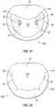
- Fig. 5Aillustrates an embodiment of a coaptation assistance device 500.
- the coaptation assistance device 500can include a coaptation assistance body 515.
- the coaptation assist body 515can include a first coaptation surface 535.
- the first coaptation surface 535can be disposed toward a mal-coapting native leaflet, in the instance of a mitral valve, the posterior leaflet when implanted.
- the coaptation assist body 515can include a second coaptation surface 540.
- the second coaptation surface 540can be opposed to the first coaptation surface 535 as shown in Fig. 5A .
- the second coaptation surface 540can be disposed toward a mal-coapting native leaflet, in the instance of a mitral valve, the anterior leaflet when implanted.
- the first coaptation surface 535 and the second coaptation surface 540can be bounded by a first lateral edge and a second lateral edge.
- the first coaptation surface 535 and the second coaptation surface 540can be bounded by an inferior edge and a superior edge 545.
- the first coaptation surface 535 and the second coaptation surface 540are two sides of the same implant structure forming the coaptation assistance body 515.
- the shape of the coaptation assistance body 515may be characterized generally, in some embodiments, by the shape of the superior edge 545, the shape of the first coaptation surface 535, and the second coaptation surface 540.
- the coaptation assistance device 500can include a ventricular projection 525 as shown in Fig. 5A .
- the ventricular projection 525can extend from the inferior edge of the coaptation assistance body 515.
- the ventricular projection 525can be placed within the left ventricle when implanted.
- the ventricular projection 525can provide an anchoring mechanism.
- the distal end 530 of the ventricular projection 525generally provides the anchoring mechanism.
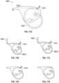
- the distal end 530 of the ventricular projection 525may have different shapes as shown in Fig. 5C.
- Fig. 5Cshows five embodiments of the distal end 530. It is noted that more variations are possible and they are not limited to the five embodiments shown in Fig. 5C .
- there are two types of anchors. Examples of passive anchorsare shown in embodiments 555.1 through 555.4 in Fig. 5C . Passive anchors rely on entrapment behind and/or interference with the chordae. With respect to the passive anchors, in some embodiments, the largest dimension or the dimension responsible for entanglement (usually the width) with the chordae may range from 10mm to 40mm, such as 25mm.
- Distal end 555.1includes one or more prongs.
- the prongscan be an elongate rod which extends from a central hub as shown. In the illustrated embodiment, four prongs extend from the central hub. In other embodiments, one or more prongs extend from the central hub. The prongs can extend at an angle from the central hub, thereby increasing the surface area of the distal end 530.
- Distal end 555.2can be generally rectangular, rectangular, generally square, square, generally diamond shaped or diamond shaped.
- the distal end 555.2can include one or more cut outs. The cut outs can increase the ability to grip tissue. In the illustrated embodiment, four cutouts are formed in the distal end. In other embodiments, one or more cut outs are provided.
- Distal end 555.3includes one or more prongs.
- the prongscan be an elongate rod which extends from a central hub as shown. In the illustrated embodiment, two prongs extend from the central hub. In other embodiments, one or more prongs extend from the central hub. The prongs can extend at a right angle from the central hub, thereby increasing the surface area of the distal end 530.
- Distal end 555.4includes one or more barbs.
- the barbscan extends from a central hub as shown.
- the barbscan extend back toward the central hub.
- three or more barbsextend from the central hub.
- one or more barbs in one or more directionsare provided.
- Distal end 555.5includes one or more prongs, and is similar to the configuration shown as distal end 555.1.
- Distal end 555.5is an example of an active anchor.
- Active anchorsmay have features such as sharp points, barbs, or screws that may couple to the ventricular tissue. Active anchors may require a driving force, such as a torque, to embed within the tissue.
- Either passive or active anchorsmay be made of implant grade biocompatible materials such as silicone, PEEK, pebax, polyurethane.
- the size of the coaptation assistance device 500is described in detail in Fig. 5D .
- This figureshows the top view and front view of the coaptation assistance body 515 of the coaptation assistance device 500.
- the three parameters "x", "y” and “z” shown in the figurecharacterize the coaptation assistance device 500. Non-limiting examples of ranges and magnitudes of these variables x, y, and z are shown in the "Dimension Table" in the figure.
- the coaptation assistance device 500can include a support structure 505.
- the support structure 505can be referred to as a spine.
- the support structure 505can define, at least in part, the shape of the coaptation assistance device 500.
- the support structure 505is shown by dotted lines.
- the support structure 505is made of a shape memory material such as but not limited to nitinol (NiTi), polyether ether ketone (PEEK) or other stiff polymer or fatigue resistant metal.
- NiTinitinol
- PEEKpolyether ether ketone
- shape memory materialsenables advantages described herein.
- one advantage of a shape memory materialis that its superelastic properties helps the coaptation assistance device 500 maintain its shape and functionality as a coaptation assistance device as the heart contracts and dilates and exerts pressure on the coaptation assistance device 500.
- Another example of an advantageis that a shape memory material lends itself to percutaneous delivery methods which will be described herein.
- the support structure 505includes two sections. In some embodiments, the support structure 505 includes three or more sections. In some embodiments, one or more sections of the support structure 505 can include one or more subsection. In the embodiment shown in Fig. 5A , the support structure 505 includes two sections: a first section 505.2 and a second section 505.1.
- the first section 505.2can extend through at least a portion of the coaptation assistance device 500 between the superior edge 545 and the ventricular projection 525. In some embodiments, the first section 505.2 can extend through the entire length between of the coaptation assistance device 500 between the superior edge 545 and the ventricular projection 525. In some embodiments, the first section 505.2 extends from a location between the superior edge 545 and the inferior edge of the coaptation assistance body 515. In some embodiments, the first section 505.2 extends from a location between the inferior edge of the coaptation assistance body 515 and the ventricular projection 525. In some embodiment, the first section 505.2 extends along the coaptation assistance body 515 and continues on to support the ventricular projection 525.
- the second section 505.1extends through at least a portion of the coaptation assist body 515 between the first lateral edge and the second lateral edge. In some embodiments, the second section 505.1 can extend through the entire length between of the first lateral edge and the second lateral edge. In some embodiments, the second section 505.1 extends from a location between the superior edge 545 and the inferior edge of the coaptation assistance body 515. In some embodiments, the second section 505.1 extends from a location closer to the superior edge 545 than the inferior edge of the coaptation assistance body 515. In some embodiments, the second section 505.1 extends from the first lateral edge toward the second lateral edge. In some embodiments, the second section 505.1 extends from the second lateral edge toward the first lateral edge. In some embodiments, the second section 505.1 extends along a section between the first lateral edge and the second lateral edge. In some embodiments, the second section 505.1 extends along the edge of the coaptation assistance device 500.
- first section 505.2 and the second section 505.1 of the support structure 505may be one integral piece or unitary structure. In some embodiments, the first section 505.2 and the second section 505.1 of the support structure 505 are separate components. In some embodiments, the first section 505.2 and the second section 505.1 may be two separate sections joined together by methods such as but not limited to crimping and laser welding.
- the first section 505.2is integrated within the coaptation assistance body 515 as described herein. In some embodiments, the first section 505.2 is integrated within the ventricular projection 525 as described herein. In the invention, the second section 505.1 is integrated within the coaptation assistance body 515 as described herein. In some embodiments, the first section 505.2 can have a first zone that is generally oriented substantially parallel to a longitudinal axis of the body 515, and a second zone that is generally oriented substantially perpendicular to the longitudinal axis of the body 515 as illustrated.
- the support structure 505 that supports the shape of the ventricular projection 525may have various cross sections as shown by section AA in Fig. 5A and illustrated in detail in Fig. 5B .
- Fig. 5Bfive embodiments of the cross-section are shown; however, it is noted that the embodiments of the cross section of the support structure 505 are not limited to these five.
- Cross-section 550.1is circular or generally circular.
- Cross-section 505.2is circular or generally circular.
- Cross-section 550.1can have a larger cross-sectional area than cross-section 550.2.
- Cross-section 550.3comprises a plurality of circular or generally circular cross-sections. In the illustrated embodiment, seven circular or generally circular cross-sections collectively form the cross-section 550.3.
- cross-section 550.3can be in the form of a cable.
- Cross-section 550.4is rectangular or generally rectangular.
- Cross-section 550.5is rectangular or generally rectangular.
- Cross-section 550.4can have a larger cross-sectional area than cross-section 550.5.
- first section 505.2 and the second section 505.1may have different cross-sections as well.
- Each cross-section or embodiment shown in Fig. 5Bmay have certain advantages such as some cross sections may bend easily in one direction and not in another. Some other cross sections may have higher reliability properties than others.
- the characteristics of each type of cross-sectionis described along with the ranges and non-limiting possible dimensions of the cross section in Table 2 in Fig. 5E for two different materials nitinol and PEEK. Although various configurations are presented in Table 2, in some embodiments, cross-sections 550.4 and 550.5 can be utilized for both materials.
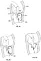
- the coaptation assistance device 500When the coaptation assistance device 500 is placed within the heart, the coaptation assistance device 500 is such that, in some embodiments, the ventricular projection 525 will generally be placed within the left ventricle as shown in Figure 5G .
- the ventricular projection 525provides a mechanism to anchor the coaptation assistance device 500 using the structure of the ventricles.
- An example of positioning of the coaptation assistance device 500 over the posterior leafletis illustrated in Fig. 5G .
- the coaptation assistance device 500is illustrated with a ventricular projection 525 that has a curved shape.
- the ventricular projection 525 and/or the first support 505.2may be composed of shape memory materials, in which case the curved shape is retained after implantation.
- the curved shapemay enable the coaptation assistance device 500 to stay in position as engages to the native posterior leaflet 14.
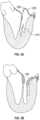
- Fig. 5Fshows an embodiment of a passive anchor for the ventricular projection 525.
- a tube 560 running along the length of the ventricular projection 525terminates in two tubes 565.1 and 565.2, at the distal end of the coaptation assistance device 500.
- the coaptation assistance device 500may be delivered to the left side of the heart with straightening wires such that the two tubes 565.1 and 565.2 are approximately straight as shown by the dotted lines 565.1 and 565.2 (Position A) indicating that the straightening wires are in an advanced state.
- the two tubes 565.1 and 565.2may be made of shape memory material including but not limited to polyurethane, silicone, polyethylene, pebax and nylon. Without the straightening wires, the two tubes 565.1 and 565.2 may have a default shape that may be curled or coiled as shown by the solid lines 565.1 and 565.2 (Position B) in Fig. 5F .
- the straightening wiresmay be withdrawn allowing the two tubes 565.1 and 565.2 to assume their default shape (Position B).
- the two tubes 565.1 and 565.2may provide anchoring support due to entanglement with the chordae.
- the advantage of this type of anchoringis that the straightening wires may be advanced back into the two tubes 565.1 and 565.2, straightening out the two tubes 565.1 and 565.2 and causing the two tubes 565.1 and 565.2 to disentangle from the chordae structure should it become necessary to reposition the coaptation assistance device 500 due to unsatisfactory placement.
- the example abovedescribes two tubes 565.1 and 565.2, it will be understood that there may be one, two, or more tubes.
- FIG. 5HYet another embodiment of anchoring the coaptation assistance device 500 is illustrated in Fig. 5H .
- An active anchormay be coupled to the distal end of the ventricular projection 525. After delivery of the implant, the active anchor may be driven through the posterior leaflet to couple to the coaptation assistance device 500 at the annular (atrial) section as shown. Methods to position and drive the anchors will be discussed herein.
- the tips of the ventricular projection 525may be radiopaque or echogenic to aid in placement and anchoring of the coaptation assistance device 500 while the coaptation assistance device 500 is being placed percutaneously.
- fluoroscopic or ultrasound imaging modalitiesmay be used to visualize the heart and the coaptation assistance device 500.
- the coaptation assistance device 500includes an annular hub 510.
- the annular hub 510can have one or more purposes. One purpose can be to serve as an anchoring device as discussed herein. Another purpose can be to provide a mechanism to deliver the coaptation assistance device 500 percutaneously as discussed herein.
- a hub(not shown) may be present at the distal end of the coaptation assistance device 500.
- the hubcan be located at the end of the ventricular projection 525.
- the ventricular hubmay be placed at the very distal tip of the distal end 530 of the ventricular projection 525.
- the hub 510 on the proximal sidewill be called the "annular hub”.
- the hub at the distal tip of the ventricular projectionwill specifically be called the "ventricular hub”.
- the coaptation assistance body 515 of the coaptation assistance device 500may be made of various biocompatible materials such as expanded polytetrafluoroethylene (ePTFE). This material provides the coaptation surface against which the anterior leaflet will close.
- ePTFEexpanded polytetrafluoroethylene
- the coaptation assistance body 515 of the coaptation assistance device 500can be coupled to the support structure 505 such that the shape of the support structure 505 gives the general shape of the coaptation assistance device 500.
- the shape of the coaptation assistance device 500may be further supported by one or more ribs 546 (not shown). There may be one, two, or more ribs 546.
- the ribs 546may be made of various materials such as but not limited to suture, polypropylene, nylon, NiTi cable, NiTi wire and PEEK. The process of coupling the coaptation assistance body 515 of the coaptation assistance device 500 to the support structure 505 and/or the ribs 546 (if ribs 546 are present) is described herein.
- the processmay commence by slipping polyethylene (PE) tubes on the support structure 505 and/or the ribs 546 (if ribs 546 are present). This combination is placed between two ePTFE sheets after which heat and pressure are applied.
- the PE tube materialmay melt into microholes in the support structure 505 and/or the ribs 546 when heat and compression are applied.
- the microholes in the support structure 505 and/or the ribs 546may be deliberately placed to improve the bonding.
- PE sheetsmay be placed where no PE tubes may be present.
- a similar process of heat and compressionis applied and a more uniform composite structure may be generated.
- the support structure 505 and/or the ribs 546may have features such as microholes that couple the ePTFE membrane.
- the micro-hole diametersmay be in the range of 0.0127cm to 0.08cm (0.005" to 0.030"), for example.
- coaptation assistance body 515 of the coaptation assistance device 500other materials such as but not limited to sponge material, polyurethane, silicone, bovine or porcine pericardium may be utilized. Bonding processes may include but may not be limited to heat bonding, suturing and gluing.
- the coaptation assistance device 500has perforations or slots 520. There may be one or multiple such perforations or slots 520. These perforations 520 can serve the purpose of providing sites where anchors may be placed as discussed herein.
- the coaptation assistance device 500may be folded into a smaller structure.
- the coaptation assistance device 500can be delivered percutaneously through a delivery catheter.
- the support structure 505is made of a shape memory material. When the coaptation assistance device 500 is unfolded inside the heart, the desired shape of the coaptation assistance device 500 is regained.
- the first supporthas a first configuration wherein the first support 505.2 is generally linear and a second configuration wherein the first support 505.2 is curved.
- the first support 505.2 and the second support 505.1are configured to permit percutaneous insertion of the coaptation assistance device 500.
- the first few steps in the delivery procedurecan be similar to those that are known in the art.
- the body of the patientis punctured for example in the lower torso/upper thigh area (groin) to get access to the femoral vein.
- a trans-septal sheath and needleare inserted into the inferior vena cava and advanced up to the atrial septum, at which point a trans-septal puncture is performed and the trans-septal sheath is advanced into the left atrium.
- the needleis removed and the trans-septal sheath now provides access to the left atrium. More details about the above steps may be found in publicly available medical literature.
- the methodcan include various steps including those that are now described.
- the ventricular projection 525 of the coaptation assistance device 500can be generally be placed within the left ventricle. It may be advantageous to guide the coaptation assistance device 500 to this location using various guiding techniques. For example a simple guidewire may be placed inside the trans-septal sheath and guided into the left ventricle by first entering the left atrium and going through the mitral valve. However, simple guidewire may not provide sufficient accuracy in placement of the ventricular projection 525.
- a method of placing a guidewire inside a steerable sheathmay be used.
- the steerable sheath with a guidewiremay be advanced through the trans-septal sheath and subsequently advanced through the mitral valve into the left ventricle where the steering ability of the steerable sheath would give additional support to position the guidewire appropriately.
- the steerable sheathrequires to be removed prior to delivery of the coaptation assistance device.
- This methodalthough providing a more accurate positioning of the guidewire, involves an extra step of removing the steerable sheath. To improve on this process in terms of reducing the number of steps needed to perform the implantation, a various embodiments of a steerable sheath are disclosed herein.
- a small diameter steerable catheter 600is illustrated.
- the diameter 615 of a handle 610 of the steerable catheter 600can be equal or substantially equal to the diameter 620 of the body 605 of the steerable catheter 600.
- the steerable catheter 600can have within it a pullwire 625.
- the handle 610is rotated, for example in the direction of the arrow 632, the distal portion of the steerable catheter 600 moves along arrow 635 from the linear position 630 to the curved position 640.
- the curved position 640may be beneficial to position the ventricular projection 625 as discussed herein.
- the distal portion of the steerable catheter 600moves along from the curved position 640 to the linear position 630.
- the linear position 630 of the steerable catheter 600is shown by dotted lines, not to be confused with the pullwire 625 which is also shown in dotted lines.
- the linear position 630may be beneficial for insertion or retraction of the steerable catheter 600 from the anatomy.
- the diameter of the handle 610can be equal to the diameter of the body 605. This can be advantageous as the coaptation assistance device 500 may slide over the handle 610 and/or the body 605 smoothly after the steerable catheter 600 is placed in the ventricle.
- the steerable catheter 600can include an extension 612 at the proximal end which extends from the handle 610.
- the extension 612can be a wire or other elongate structure. The purpose of the extension 612 is to aid in the loading of other catheters or devices while allowing a physician or other operators to retain control of the steerable catheter 600. Subsequent to loading of the other catheters or devices on the extension 612, the steerable catheter 600 is utilized to guide the other catheters or devices.
- the length of the extension 612can match or exceed the length of the catheter or device that is being loaded such that during the process of loading and delivering the other catheter or device, control of the steerable catheter 600 is retained.
- the extension 612may be coupled to the handle 610 only when necessary. For example if during a procedure, the medical team decides that a longer catheter is necessary, the extension 612 may be coupled to the handle 610. Coupling mechanisms may include but are not limited to a threaded junction, a compression fit, or other mechanisms.
- Non-limiting examples of dimensions of the various subcomponents in some embodimentscan be as follows: the diameter 620 of the body 605 may range from 2 to 10 Fr, such as 4 Fr, between about 2 Fr and about 6 Fr, between about 3 Fr and about 5 Fr, or less than 10 Fr, 9 Fr, 8 Fr, 7 Fr, 6 Fr, 5 Fr, 4 Fr, 3 Fr, or 2 Fr (wherein 1Fr equals 0.33mm).
- the handle 610 lengthmay range in some cases from about 1,27cm to 5.08cm (1 ⁇ 2" to about 2"), such as about 2.54cm (1"), the handle linear travel (for pullwire activation) may range in some cases from about 0.375cm to about 7,62cm (1/8" to about 3"), such as about 0.635cm (1 ⁇ 4").
- the steerable catheter 600may be advanced through the femoral access. Since the handle 610 is outside the patient's body, it may be rotated such that the distal portion of this steerable catheter 600 is placed in an appropriate position under the posterior leaflet.
- the extension 612can be attached to the proximal end of the handle 610 to allow subsequent loading of the coaptation assistance device 500 and delivery catheter 700 prior to insertion into the trans-septal sheath 650, described herein.
- This delivery catheter 700may then be used as a guide for introducing the coaptation assistance device 500 as will be explained herein.
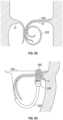
- Fig. 6Billustrates the placement of the steerable catheter 600 in the heart.
- An embodiment of the trans-septal sheath 650is shown.
- the left atrium 655, left ventricle 660, the posterior leaflet 665 of the mitral valve and the anterior leaflet 670 of the mitral valveare also shown.
- the steerable catheter 600is shown going through the mitral valve and being positioned under the posterior leaflet 665. It may be now appreciated how having the ability to deflect the distal potion of steerable catheter 600 can be advantageous so that an appropriate position of the coaptation assistance device 500 may be achieved.
- the distal portion of the steerable catheter 600is able to curve under the posterior leaflet 665 as shown.
- the next general step after placing the steerable catheter 600is to deliver the coaptation assistance device 500 to the heart. Further embodiments are now described with regards to methods and devices to achieve delivery.
- the function of the delivery catheter 700is to carry the coaptation assistance device 500 to the heart.
- the shaft body 710 of the delivery catheter 700can be torqueable and deflectable.
- the shaft body 710is shown by the cross hatched lines.
- the delivery catheter 700can include a handle 730.
- the handle 730can have rotation mechanisms, for example pull wires etc. The rotation mechanism can deflect and steer the shaft body 710.
- Distal to the handle 730is an implant sheath 725 which as explained herein may carry the coaptation assistance device 500 to the heart.
- a tear away funnel 720is a tear away funnel 720.
- the tear away funnel 720can facilitate the folding of the coaptation assistance device 500.
- the most distal end of the shaft body 710has features that may lock the shaft body 710 to the coaptation assistance device 500 so that the coaptation assistance device 500 may be transported to the heart and placed appropriately. The locking process and features are now described in relation to Figs. 7B , 7C and 7D .
- the delivery catheter 700 and the coaptation assistance device 500can have matching features that enable them to be locked temporarily.
- the delivery catheter 700includes one or more distal locking tabs 705.
- the coaptation assistance device 500can include the annular hub 510 as described herein.
- the distal locking tabs 705 of the delivery catheter 700may couple with features in the annular hub 510 of the coaptation assistance device 500 as will be explained herein.
- the steerable catheter 600 or other guiding wires or cathetersmay be advanced through the ventricular projection 525 and/or anchoring mechanism 530.
- the anchoring mechanism 530can have a hole or passageway in the center to allow the steerable catheter 600 to pass through, as shown in Fig. 7D .
- the steerable catheter 600can pass from the anchoring mechanism 530 to the annular hub 510.
- Other paths through the coaptation assistance device 500are contemplated.
- the steerable catheter 600can pass from the anchoring mechanism 530 to the annular hub 510 and further to the delivery catheter 700.
- a guidewire or a catheter such as steerable catheter 600can be inserted into the annular hub 510 and between the distal locking tabs 705, and the distal locking tabs 705 can be pushed out against the annular hub 510.
- the annular hub 510is designed with matching pockets 740 such that the distal locking tabs 705 fit into these pockets 740.
- the annular hub 510can include a cross-pin 745.
- the cross-pin 745can be a solid piece that goes across the annular hub 510 and is held in place by methods that are known in the art.
- the delivery catheter 700can include a loop of wire or suture 750.
- the suture 750which may loop around an object such as a guidewire or the steerable catheter 600 within the annular hub 510.
- the suture 750may extend into the handle 730 of the delivery catheter 700.
- the handle 730may have a mechanism which controls the tension of the suture 750.
- the coaptation assistance device 500can be pulled against and held securely to the distal end of the delivery catheter 700.
- the loop 755 of the suture 750can slip over the cross-pin 745, thereby releasing the cross-pin 745 and the coaptation assistance device 500.
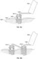
- Figs. 8A-8Dshow a method of delivery.
- the implant sheath 725 and the funnel 720are advanced over the coaptation assistance device 500.
- the implant sheath 725 and the funnel 720can be advanced over the coaptation assistance device 500 after the delivery catheter 700 is locked with the coaptation assistance device 500.
- the shape of the funnel 720aids in the coaptation assistance device 500 closing or folding in on itself.
- the advancement of the implant sheath 725 and the funnel 720is shown in Figs. 8A and 8B .
- the arrow 760 in Fig. 8Aindicates how the coaptation assistance device 500 is pulled into the funnel 720. Once the coaptation assistance device 500 is within the implant sheath 725, the funnel 720 is removed.
- the funnel 720is removed by pulling on a tab 715, thereby splitting the funnel 720, shown in Fig. 8C .
- the funnel 720 and the tab 715can be then discarded.
- the implant sheath 725 containing the coaptation assistance device 500can be advanced over the guidewire or the steerable catheter 600.
- the advantage of the design of the steerable catheter 600becomes evident as the coaptation assistance device 500 can glide smoothly over the steerable catheter without having any difficulty due to different size diameters of the handle 610 and the body 605.
- the implant sheath 725can be inserted into the trans-septal sheath 650 as shown Fig. 8D .
- the system of the coaptation assistance device 500 and the implant sheath 725is advanced until it exits the trans-septal sheath 650 as shown in Fig. 8E .
- the delivery catheter 700is deflected such that the implant sheath 725 is positioned between the leaflets of the mitral valve, which is shown in Fig. 8E .
- the implant sheath 725is placed between the chordae 765 ("P2" location). Once the implant sheath 725 attains this position, the delivery catheter 700 is held in place and the implant sheath 725 is retracted slowly, causing the coaptation assistance device 500 to start exiting the implant sheath 725 as illustrated in Fig. 8F .
- the steerable catheter 600 or an equivalent guide wireis still in place under the posterior leaflet and can still be actively adjusted or deflected using the control handle 610.
- the coaptation assistance device 500is pushed out, following the path of the steerable catheter 600 until the distal end 530 of the ventricular projection 525 is coupled to the ventricular tissue. This is illustrated in Fig. 8G . While the coaptation assistance device 500 is being pushed out, the implant sheath 725 can be retracted. In some methods, rotational adjustments may be made to the delivery catheter 700 to ensure appropriate placement.
- the methodcan include the step of anchoring the coaptation assistance device 500 on the atrial aspect of the mitral valve namely, on the on the mitral valve annulus.
- a support structure 505 made of a shape memory materialcan be advantageous. As the coaptation assistance device 500 opens, the coaptation assistance device 500 assumes the shape that was intended due to the action of the shape memory material.
- the shape of the coaptation assistance device 500as described herein, can be intended to provide a new coaptation surface so that regurgitant flows are reduced or eliminated.
- the delivery catheter 700which can be still coupled to the annular hub 510 of the coaptation assistance device 500, may now be manipulated (rotationally and axially) to position the coaptation assistance device 500 appropriately over the posterior leaflet of the native valve.
- the support structure 505 of the coaptation assistance device 500may have features which may attach to the tissue.
- these featuresare passive hooks. In some methods, these features engage the annulus such that the coaptation assistance device 500 may be held in place while anchoring is commenced.
- Fig. 8Hshows the state of the delivery catheter 700 with the implant sheath 725 retracted and the shaft body 710 still coupled to the annular hub 510.
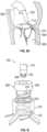
- the anchor 800may be coupled to the delivery catheter 700 and/or the coaptation assistance device 500 in various ways.
- the annular hub 510has a cross-pin 512.
- the cross-pin 512provides a site about which a helical structure 815 of the anchor 800 may wrap around as shown.
- the anchor 800can have a shoulder 805.
- the shoulder 805may fit around the shaft body 710 of the delivery catheter 700.
- the shoulder 805may have features such as windows 810 which can lock the distal locking tabs 705 of the delivery catheter 700.
- the distal locking tabs 705 of the delivery catheter 700can lock when a pin, guidewire or a catheter such as the steerable catheter 600 is present within the shaft body 710 of delivery catheter 700.
- the anchor 800can be preloaded onto the coaptation assistance device 500 and locked in place with the delivery catheter 700 during the process of mounting the coaptation assistance device 500 onto the delivery catheter 700. This can occur prior to when the coaptation assistance device 500 is pulled into the implant sheath 725 and being readied for insertion into the femoral vein.
- torquecan be applied to the shaft body 710 such that the anchor 800 is driven into the tissue.
- fluoroscopic markersmay be present on the anchor 800. The markers may be located at the proximal end. These markers may inform the medical team about how far the anchor 800 may have travelled towards the annular hub 510 and may be informative about when the anchor 800 is securely in place.
- the torque level at the handle 730may spike as the anchor 800 bottoms out on the annular hub 510. This increased torque level may be felt at the handle 730 providing feedback that appropriate torque has been applied.
- the central guidewire or the steerable catheter 600can be retracted. This causes the distal locking tabs 705 to fall back from the windows 810 of the anchor 800, thus unlocking the delivery catheter 700 and the anchor 800. This can cause the releasing the coaptation assistance device 500.
- the delivery catheter 700 and steerable catheter 600may now be completely retracted.
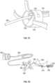
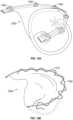
- FIG. 9AOne such embodiment is shown in Fig. 9A .
- the delivery catheter 700(not shown) has been retracted and an anchor catheter 900 has been advanced through the femoral access.
- the anchor catheter 900is torqueable.
- One or more anchor catheters 900can be provided.
- the distal tip of the anchor catheter 900may have one or more features to lock the anchors in place during the delivery of the anchor.
- the distal tiphas a cut-out 905 which may receive a portion of the helical anchor 915.
- the anchor catheter 900may also have central pin 920.
- the central pin 920can have a pointed end on the distal tip. In some embodiments, the central pin 920 can have the ability to be retracted.
- Fig. 9Ashows a loop 910.
- the ends (not shown) of the loop 910may travel to the handle of the anchor catheter 910 or some length therebetween such that the tension of the loop 910 may be controlled.
- the loop 910go over a crossbar 917 or other portion which forms the proximal part of the helical anchor 915.
- the top view of the helical anchor 915 with the crossbar 917is shown in Fig. 9B . While outside the body, prior to entry into the trans-septal sheath (not shown), the helical anchor 915 may be placed adjacent to the central pin 920.
- the loop 910may be arranged in such a manner that when tension is applied to the loop 910, the loop 910 keeps the helical anchor 915, and the central pin 920 locked in place. In Fig. 9A , this arrangement is retracted so that the cutouts 905 receive the proximal portion of the helical anchor 915. Keeping the loop 910 in tension, the entire arrangement is advanced into the trans-septal sheath.
- the anchor catheter 900is adjusted so that the distal end of the anchor catheter 900 is positioned over a commissure hole 520.
- the central pin 920 and the helical anchor 915are advanced such that the central pin 920 first pierces the tissue after going through a commissure hole 520. Torque is applied to the anchor catheter 900 and the helical anchor 915 pierces the tissue.
- the helical anchor 915anchors the support structure 505 or frame of the coaptation assistance device 500 to the tissue. After the helical anchor 915 is in place, the central pin 920 is retracted.
- the retraction of the central pin 920can allows the loop 910 to slip over the crossbar 917 of the helical anchor 915, thereby releasing the anchor 915. This process can be repeated for the other commissure site to anchor both extreme projections of the coaptation assistance device 500.
- a delivery catheter 1000may have multiple lumens 1040.
- the delivery catheter 1000may have a cross-section as shown in Fig. 10B .
- the lumens 1040may carry individual torqueable drive shafts. Each drive shaft can be locked onto an anchor as the case is for shafts 1020 and 1030 or onto the annular hub 510 as is shown for shaft 1010.
- Each torqueable shaft 1010, 1020, 1030may have the design of the anchor catheter 900 illustrated in Fig. 9A .
- the delivery catheter 1000may have a central lumen 1050 through which a guidewire or the steerable catheter 600 may pass.
- the multiple torqueable drive shafts 1010, 1020, 1030, a guidewire or the steerable catheter 600 along with the coaptation assistance device 500can all be loaded and retracted into the implant sheath of the delivery catheter 1000 prior to entry into the trans-septal sheath.
- This entire arrangementcan be advanced and the same procedure as explained herein can be followed to place the coaptation assistance device 500.
- the advantageous aspect of this arrangementis that the anchoring process may be accomplished without the need to retract the anchor catheter multiple times, reloading the anchors and reentering the body.
- Fig. 11Ashows an anchor with grappling hooks.
- Fig. 11Bshows an anchor that resembles an umbrella.
- the anchorsmay be made of a shape memory material.
- the anchorsmay be loaded into a delivery catheter such as the delivery catheter illustrated in Fig. 11C .
- Locking mechanismssuch as those described herein may be used to lock the anchors to the delivery catheter.
- the delivery cathetermay have a pointed end so that the delivery catheter may be guided to an appropriate location and initially pierce the tissue. After the delivery catheter is placed at an appropriate location and the initial piercing is accomplished, one or more of the anchors may be advanced and set in place. This step is followed by unlocking and retracting the delivery catheter.
- Fig. 11Dis an illustration of how the umbrella anchor of Fig. 11B may look after it has been set into the tissue to anchor the coaptation assistance device 500. Due to the natural unstressed shape of the anchor, when deployed in the tissue over the coaptation assistance device 500, the deformed shape would have an effective spring-force on the face of the coaptation assistance device 500, ensuring a good foothold.
- the coaptation assistance device 500 described in Figs. 5A-Fcan include the support structure 505.
- the support structure 506can be made of shape memory material as described herein.
- another configurationis contemplated. This configuration can be called the spineless coaptation assistance device to indicate that the support structure is removed after placement of the coaptation assistance device in the heart. Both types of coaptation assistance devices can have certain advantages.
- the spineless coaptation assistance devicemay be advantageous due to fewer components and materials and no possible metal fatigue.
- Fig. 12shows an embodiment of the spineless coaptation assistance device 1200.
- the spineless coaptation assistance device 1200can include a tube or a passageway 1210.
- the passageway 1210can be placed around the annular edge. This passageway 1210 can be called the annular tube.
- the spineless coaptation assistance device 1200can include a tube or passageway 1212 along the ventricular projection. This passageway 1212 can be called the ventricular tube.
- the profile of the passageway 1210can be shown towards the ends of the annular tube. Although a circular profile is illustrated, the tubes or passageways 1210, 1212 may have other profiles including but not limited to oval and flat.
- the support structure 1210.1, 1210.2, 1210.3is shown by dotted lines except at the annular edges where the support structures 1210.1 and 1210.3 protrude.
- the support structure 1210.1, 1210.2, 1210.3may have three distinct sections, where 1210.1 and 1210.3 are placed in the annular tube and 1210.2 is placed in the ventricular tube.
- the support structure 1210.1, 1210.2, 1210.3can be coupled within a spine hub 1220.
- the support structure 1210.1, 1210.2, 1210.3may be distinct and separate sections.
- the support structure 1210.1, 1210.2, 1210.3may be joined together by using one of various methods such as, but not limited to, crimping and laser welding.
- This arrangement of the support structure 1210.1, 1210.2, 1210.3 and the coaptation assistance device 1200allows the support structure 1210.1, 1210.2, 1210.3 to be extracted from the coaptation assistance device 1200.
- the support structure 1210.1, 1210.2, 1210.3is extracted by applying a pulling force on spine hub 1220. More detail about the coaptation assistance device 1200, and the procedure to deliver and anchor the coaptation assistance device 1200, will be provided herein.
- Figs. 13A and 13Billustrate the delivery procedure of the coaptation assistance device 1200.
- Fig. 13Ashows the coaptation assistance device 1200 of Fig. 12 .
- Fig. 13Ashows an additional feature, an anchor site 1300. This anchor site 1300 will be described in greater detail herein.
- the steerable catheter 600can inserted into the coaptation assistance device 1200.
- the steerable catheter 600can be inserted from the distal tip of the ventricular projection 1212.
- the steerable catheter 600can exits from an exit aperture 1335.
- a delivery catheter 1320can be provided.
- the delivery catheter 1320can include a torqueable shaft 1310.
- the delivery catheter 1320can include a hub locking feature 1330 that couples with a hub anchor 1300. In Fig. 13A , the hub locking feature 1330 is shown as a screw. Other locking mechanisms explained herein may be utilized.
- Fig. 13Billustrates more detail with regard to the delivery catheter 1320.
- the distal tip of the delivery catheter 1320can include a funnel 1360. Proximal to the funnel 1360, an implant introducer 1340 may be present. At the very proximal end, the delivery catheter 1320 may have a handle 1370.
- the steerable catheter 600can be threaded through the coaptation assistance device 1200 as described herein.
- the funnel 1360can be inserted on to the distal tip of the delivery catheter 1320.
- the coaptation assistance device 1200can be locked in place using the locking feature 1330, such that the hub anchor 1300 is connected to the torqueable shaft 1310.
- the steerable catheter 600can be threaded through an angled side port 1350 on the implant introducer 1340.
- the coaptation assistance device 1200 and the steerable catheter 600can be pulled through the funnel 1360 by retracting the delivery catheter 1320. With continued retraction, the coaptation assistance device 1200 will fold upon itself within the implant introducer 1340.
- the funnel 1360is removed and discarded.
- the funnel 1360may be designed such that it may be easily removed. Designs for the funnel include but are not limited to the peel away design (shown previously in Figs. 8A-8C ) or a clamshell design ( Fig. 13B ).
- the delivery catheter 1320 along with the implant introducer 1340can be advanced over the steerable catheter 600 until the implant introducer 1340 couples with the hub of the trans-septal sheath 650. At this point, the implant introducer 1340 may not be able to advance further but the coaptation assistance device 1200 itself can be advanced into the trans-septal sheath.
- the next several stepsare similar to that shown in Figs. 8E through 8G , except in this example, no implant sheath is used.
- the coaptation assistance device 1200is placed over the posterior leaflet and the ventricular projection 1212 is placed in the left ventricle.
- the steerable catheter 600can be retracted allowing the ventricular projection 1212 to curl or coil under P2.
- the hub anchor 1300can be rotated or otherwise activated.
- the hub anchor 1300can anchor the proximal side of the coaptation assistance device 1200 to the annulus.
- the torqueable shaft 1310can retracted.
- the hub locking feature 1330is retracted pulling the support structure 1210.1, 1210.2, 1210.3 along with it.
- the coaptation assistance device 1200may now be operational in the left heart without the support structure 1210.1, 1210.2, 1210.3.
- Fig. 14Ashows an embodiment for anchoring the coaptation assistance device 1200.
- the coaptation assistance device 1200may need additional anchors.
- the coaptation assistance device 1200may utilize closely spaced anchors.
- the coaptation assistance device 1200may utilize additional and closely spaced anchors than a similar coaptation assistance device with a support structure 505, described herein.
- Fig. 14Ashows an embodiment of anchors 1400, which may be used to couple the coaptation assistance device 1200 and the tissue.
- Fig. 14Bshows another embodiment. In Fig.
- a suture or tape 1410is used to "sew" the coaptation assistance device 1200 to the tissue.
- the suture or tape 1410may be made of one of several materials including, but not limited to, polypropylene or nylon.
- Fig. 15Ashows an embodiment of an anchor catheter 1500 that delivers multiple anchors.
- Several anchors 1510including anchor 1510.1 and anchor 1510.2, are stacked within the anchor catheter 1500.
- Fig. 15Ashows two anchors 1510.1 and 1510.2 stacked within the anchor catheter 1500, more or fewer anchors may be stacked.
- Each anchor 1510may include a coil section 1550.
- the coil section 1550can include a pointed end 1570.
- the anchor 1510may include an anchor head 1560.
- the anchor head 1560may have one of several cross sections shown by 1545.1, 1545.2, 1545.3 and 1545.4 in Fig. 15A . Other cross sections are possible.
- the anchors 1510are loaded onto a central shaft 1520 of the anchor catheter 1500.
- the central shaft 1520 and the anchors 1510may have a matching cross section such that the anchors 1510 may be rotationally coupled to the central shaft 1520.
- a spring 1540can be included at the proximal end of the anchor catheter 1500. This spring 1540 provides a pushing force such that as the central shaft 1520 is rotated, the anchors 1510 exit the distal end of the anchor catheter 1500 in the direction of arrow 1550. As the anchors 1510 exit, the anchor 1510 can engage with the coaptation assistance device 1200 and the tissue to couple the coaptation assistance device 1200 to the tissue.
- the rotation of the central shaft 1520may be controlled by an operator such as a doctor.
- the central shaft 1520is coupled to a torqueable wire
- the torqueable wiremay be controlled manually. In some embodiments, the torqueable wire may be controlled via an electric motor. Other methods to impart a rotational motion to the central shaft 1520 are contemplated.
- a feature that is not shown in the Fig. 15Ais the ability to steer and position the distal end of the anchor catheter 1500. As one anchor 1510 is delivered, the distal tip may need to be repositioned to deliver the next anchor 1510. A steering mechanism such as pull wires may be included to steer the distal tip of the anchor catheter 1500.
- Fig. 15Bshows another embodiment of an anchor catheter 1600 that delivers multiple anchors.
- Fig. 15Bshows only the distal tip of an anchor catheter 1600.
- the anchor catheter 1600can include multiple anchors 1610 such as 1610.1 and 1610.2. Although the anchor catheter 1600 shows five anchors, more or fewer anchors 1610 may be loaded at any one time.
- the anchor catheter 1600may have a central shaft 1630.
- the anchor catheter 1600can include threads such as 1620 on the inside of the housing 1605. These threads 1620 can house the coils of the anchors 1610 as shown. To initially load the anchor catheter 1600, the anchors 1610 are inserted into the housing 1605. The anchors 1610 are inserted onto the central shaft 1630.
- the cross-section of the central shaft 1630may match the cross-section of the anchors 1610 so that the anchors 1610 may be mounted on the central shaft 1630.
- the rotation of the central shaft 1630may be controlled by a torqueable cable (not shown) which may couple the central shaft 1630 to a handle (not shown) of the anchor catheter 1600.
- the operatorsuch as a doctor may control the rotation.
- the torqueable wiremay be controlled manually.
- the torqueable wiremay be controlled via an electric motor. As the central shaft 1630 rotates, the threads will force the anchors 1610 to exit the anchor catheter 1600 and engage with the coaptation assistance device 1200 and the tissue to couple the coaptation assistance device 1200 and the tissue together.
- the anchor catheter 1600may also have pull wires to steer the distal tip of the anchor catheter 1600 so that as one anchor 1610 is delivered, the anchor catheter 1600 may be positioned to deliver the next anchor 1610.
- Fig. 15Billustrates a central suture 1635.
- the central suture 1635can include a ball 1640 coupled to the end of the central suture 1635.
- Figs. 15C and 15Dillustrate how the central suture 1635 and ball 1640 may be used.
- the ball 1640can sit in a pocket inside the first anchor 1610.1.
- the central suture 1635can connect the first anchor 1610.1 to the second anchor 1610.2 and others anchors 1610 (not shown in the figure).
- This arrangementmay provide the ability to use the central suture 1635 as a guide wire to return back to an anchor 1610 after the anchor 1610 has been screwed into the tissue 1645.
- the operatormay wish to return to the anchor 1610 to reposition or adjust the anchor 1610.
- the central suture 1635may provide a tether for the loose anchors 1610, therefore preventing embolic events.
- Fig. 16A-Cshows another embodiment of an anchor catheter 1700 that delivers multiple anchors.
- the anchor catheter 1700can have a hollow shaft.
- the hollow shaftcan be pointed at the distal end which may be used to pierce the coaptation assistance device 1200 and tissue.
- Multiple anchors 1710such as 1710.1, 1710.2 may be arranged within the hollow shaft of the anchor catheter 1700.
- the anchors 1710can be hollow barrels.
- a suture 1720may be threaded through the anchors 1710 as shown.
- the suture 1720may be secured to the first anchor 1710.1 by arranging the suture 1720 to exit the second anchor 1710.2 and enter the first anchor 1710.1 through a side aperture 1740.
- the suture 1720may then be secured by means of a knot as depicted in dotted lines within the first anchor 1710.1.
- the suture 1720 in the other anchors 1710, except the first anchor 1710.1,may appear as illustrated for the anchor 1710.2.
- the anchors 1710, except the first anchor 1710.1have a portion of their walls cut out. The cut outs can aids in better trapping the anchors within the tissue, similar to a toggle-bolt.
- a featuresuch as a pusher tube 1750 may be present to cause the anchors 1710 such as 1710.1 and 1710.2 to exit the anchor catheter 1700 at the distal end.
- the pusher 1750may be attached to a handle (not shown) so as to enable an operator such as a doctor to deposit one or more anchors 1710 when appropriate.
- the arrow 1760indicates the direction of the push.
- Fig. 16B-Cillustrates how the anchor catheter 1700 of Fig. 16A may operate.
- the anchor catheter 1700is advanced through the coaptation assistance device 1200 through a slot such as described by 520 in Fig. 5A .
- the anchor catheter 1700then pierces the tissue 1645.
- the operatorpushes the first anchor 1710.1 out of the anchor catheter 1700, depositing the anchor 1710.1 within the tissue.
- the rest of the anchors 1710are deposited as illustrated in Fig. 16C .
- the anchor catheter 1700is pulled out of the tissue after depositing the first anchor 1710.1 in order to enter a second location.
- the anchor catheter 1700can deposit the second anchor 1710.2. This process is continued until desired to secure the coaptation assistance device 1200 to the tissue.
- a cutter(not shown) can be advanced inside the anchor catheter 1700 to cut the suture 1720, leaving behind the anchors 1710.
- the anchors 1710may be radio opaque or they may be covered by a radio graphic marker. During the process of delivery of the anchors 1710, the radio opaque markers may be visualized if a fluoroscope is used. This may help in spacing the anchors 1710 around the annulus of the coaptation assistance device 1200.
- the MRis assessed while securing the coaptation assistance device 1200 and the pitch and/or the location of the sewing action is determined according to the presence or absence of the MR
- Fig. 17Aillustrates another embodiment of a spineless coaptation assistance device 1800.
- the support structure 1810may only traverse down the ventricular projection 1820.
- a tube or passageway 1830may be present around the annular edge of the coaptation assistance device 1800.
- an anchor catheter 1850can be inserted into the tube 1830 as shown in Fig. 17B .
- the anchor catheter 1850can be a deflectable anchor catheter.
- Fig. 17Balso shows a first site 1860.1 where an anchor such as that described by 1560 in Fig. 15A can be delivered.
- an anchorsuch as that described by 1560 in Fig. 15A can be delivered.
- the anchors(not shown) may be delivered securing the coaptation assistance device 1800 to the tissue.
- the tip of the anchor catheter 1850may be radio opaque which may then be visualized during the anchor delivery process. The visualization of the tip may be utilized to locate the anchors around the annulus of the coaptation assistance device 1800.
- Fig. 17Billustrates a first anchor location 1860.1
- Fig. 17Cillustrates a second anchor location 1860.2.
- the anchor catheter 1850is retracted completely as shown in Fig. 17D .
- the support structure 1810can be removed as shown in Fig. 17E .
- the support structure 1810may not be limited only to the ventricular projection; it may also be inserted through the annular tube 1830 such that a desired shape may be maintained.
- the support structurecan be a shape memory material. Utilizing a support structure around the annular tube 1830 may result in an anchor catheter which may have relatively simpler control mechanisms compared to the anchor catheter 1850 used for the coaptation assistance device 1800 described in Fig. 17A .
Landscapes
- Health & Medical Sciences (AREA)
- Cardiology (AREA)
- Life Sciences & Earth Sciences (AREA)
- Public Health (AREA)
- Animal Behavior & Ethology (AREA)
- Engineering & Computer Science (AREA)
- Biomedical Technology (AREA)
- Heart & Thoracic Surgery (AREA)
- Veterinary Medicine (AREA)
- General Health & Medical Sciences (AREA)
- Surgery (AREA)
- Oral & Maxillofacial Surgery (AREA)
- Transplantation (AREA)
- Vascular Medicine (AREA)
- Molecular Biology (AREA)
- Nuclear Medicine, Radiotherapy & Molecular Imaging (AREA)
- Medical Informatics (AREA)
- Rheumatology (AREA)
- Prostheses (AREA)
Description
- The present invention generally provides improved medical devices, and systems typically for treatment of heart valve disease and/or for altering characteristics of one or more valves of the body. Embodiments of the invention include implants for treatment of mitral valve regurgitation.
- The human heart receives blood from the organs and tissues via the veins, pumps that blood through the lungs where the blood becomes enriched with oxygen, and propels the oxygenated blood out of the heart to the arteries so that the organ systems of the body can extract the oxygen for proper function. Deoxygenated blood flows back to the heart where it is once again pumped to the lungs.
- The heart includes four chambers: the right atrium (RA), the right ventricle (RV), the left atrium (LA) and the left ventricle (LV). The pumping action of the left and right sides of the heart occurs generally in synchrony during the overall cardiac cycle.
- The heart has four valves generally configured to selectively transmit blood flow in the correct direction during the cardiac cycle. The valves that separate the atria from the ventricles are referred to as the atrioventricular (or AV) valves. The AV valve between the left atrium and the left ventricle is the mitral valve. The AV valve between the right atrium and the right ventricle is the tricuspid valve. The pulmonary valve directs blood flow to the pulmonary artery and thence to the lungs; blood returns to the left atrium via the pulmonary veins. The aortic valve directs flow through the aorta and thence to the periphery. There are normally no direct connections between the ventricles or between the atria.
- The mechanical heartbeat is triggered by an electrical impulse which spreads throughout the cardiac tissue. Opening and closing of heart valves may occur primarily as a result of pressure differences between chambers, those pressures resulting from either passive filling or chamber contraction. For example, the opening and closing of the mitral valve may occur as a result of the pressure differences between the left atrium and the left ventricle.
- At the beginning of ventricular filling (diastole) the aortic and pulmonary valves are closed to prevent back flow from the arteries into the ventricles. Shortly thereafter, the AV valves open to allow unimpeded flow from the atria into the corresponding ventricles. Shortly after ventricular systole (i.e., ventricular emptying) begins, the tricuspid and mitral valves normally shut, forming a seal which prevents flow from the ventricles back into the corresponding atria.
- Unfortunately, the AV valves may become damaged or may otherwise fail to function properly, resulting in improper closing. The AV valves are complex structures that generally include an annulus, leaflets, chordae and a support structure. Each atrium interfaces with its valve via an atrial vestibule. The mitral valve has two leaflets; the analogous structure of the tricuspid valve has three leaflets, and opposition or engagement of corresponding surfaces of leaflets against each other helps provide closure or sealing of the valve to prevent blood flowing in the wrong direction. Failure of the leaflets to seal during ventricular systole is known as malcoaptation, and may allow blood to flow backward through the valve (regurgitation). Heart valve regurgitation can have serious consequences to a patient, often resulting in cardiac failure, decreased blood flow, lower blood pressure, and/or a diminished flow of oxygen to the tissues of the body. Mitral regurgitation can also cause blood to flow back from the left atrium to the pulmonary veins, causing congestion. Severe valvular regurgitation, if untreated, can result in permanent disability or death.
- A variety of therapies have been applied for treatment of mitral valve regurgitation, and still other therapies may have been proposed but not yet actually used to treat patients. While several of the known therapies have been found to provide benefits for at least some patients, still further options would be desirable. For example, pharmacologic agents (such as diuretics and vasodilators) can be used with patients having mild mitral valve regurgitation to help reduce the amount of blood flowing back into the left atrium. However, medications can suffer from lack of patient compliance. A significant number of patients may occasionally (or even regularly) fail to take medications, despite the potential seriousness of chronic and/or progressively deteriorating mitral valve regurgitation. Pharmacological therapies of mitral valve regurgitation may also be inconvenient, are often ineffective (especially as the condition worsens), and can be associated with significant side effects (such as low blood pressure).
- A variety of surgical options have also been proposed and/or employed for treatment of mitral valve regurgitation. For example, open-heart surgery can replace or repair a dysfunctional mitral valve. In annuloplasty ring repair, the posterior mitral annulus can be reduced in size along its circumference, optionally using sutures passed through a mechanical surgical annuloplasty sewing ring to provide coaptation. Open surgery might also seek to reshape the leaflets and/or otherwise modify the support structure. Regardless, open mitral valve surgery is generally a very invasive treatment carried out with the patient under general anesthesia while on a heart-lung machine and with the chest cut open. Complications can be common, and in light of the morbidity (and potentially mortality) of open-heart surgery, the timing becomes a challenge-sicker patients may be in greater need of the surgery, but less able to withstand the surgery. Successful open mitral valve surgical outcomes can also be quite dependent on surgical skill and experience.
- Given the morbidity and mortality of open-heart surgery, innovators have sought less invasive surgical therapies. Procedures that are done with robots or through endoscopes are often still quite invasive, and can also be time consuming, expensive, and in at least some cases, quite dependent on the surgeon's skill. Imposing even less trauma on these sometimes frail patients would be desirable, as would be providing therapies that could be successfully implemented by a significant number of physicians using widely distributed skills. Toward that end, a number of purportedly less invasive technologies and approaches have been proposed. These include devices which seek to re-shape the mitral annulus from within the coronary sinus; devices that attempt to reshape the annulus by cinching either above to below the native annulus; devices to fuse the leaflets (imitating the Alfieri stitch); devices to re-shape the left ventricle, and the like.
- Perhaps most widely known, a variety of mitral valve replacement implants have been developed, with these implants generally replacing (or displacing) the native leaflets and relying on surgically implanted structures to control the blood flow paths between the chambers of the heart. While these various approaches and tools have met with differing levels of acceptance, none has yet gained widespread recognition as an ideal therapy for most or all patients suffering from mitral valve regurgitation.
- Because of the challenges and disadvantages of known minimally invasive mitral valve regurgitation therapies and implants, still further alternative treatments have been proposed. Some of the alternative proposals have called for an implanted structure to remain within the valve annulus throughout the heart beat cycle. One group of these proposals includes a cylindrical balloon or the like to remain implanted on a tether or rigid rod extending between the atrium and the ventricle through the valve opening. Another group relies on an arcuate ring structure or the like, often in combination with a buttress or structural crossmember extending across the valve so as to anchor the implant. Unfortunately, sealing between the native leaflets and the full perimeter of a balloon or other coaxial body may prove challenging, while the significant contraction around the native valve annulus during each heart beat may result in significant fatigue failure issues during long-term implantation if a buttress or anchor interconnecting cross member is allowed to flex. Moreover, the significant movement of the tissues of the valve may make accurate positioning of the implant challenging regardless of whether the implant is rigid or flexible.
- In light of the above, it would be desirable to provide improved medical devices, systems, and methods. It would be particularly desirable to provide new techniques for treatment of mitral valve regurgitation and other heart valve diseases, and/or for altering characteristics of one or more of the other valves of the body. The need remains for a device which can directly enhance leaflet coaptation (rather than indirectly via annular or ventricular re-shaping) and which does not disrupt leaflet anatomy via fusion or otherwise, but which can be deployed simply and reliably, and without excessive cost or surgical time. It would be particularly beneficial if these new techniques could be implemented using a less-invasive approach, without stopping the heart or relying on a heart-lung machine for deployment, and without relying on exceptional skills of the surgeon to provide improved valve and/or heart function. Document
US2012/197388 discloses an anchoring system according to the preamble ofclaim 1. - The present invention is disclosed in the appended set of claims. In some embodiments, disclosed herein is an implant for treating mal-coaptation of a heart valve. The implant can include one or more of a shape memory structure, a biocompatible membrane coupled to the structure, a hub placed on the proximal side of the implant and coupled to the membrane, one, two, or more holes or perforations along the edge of the membrane on the proximal side, and a ventricular projection coupled to an anchoring device. The implant can be folded for delivery through a percutaneous catheter. A shape memory structure can include a shape memory spine, such as nitinol or PEEK for example. A part of the ventricular projection, such as the distal tip, can be radiopaque. The anchoring device could be active, or passive. The spine can include features such as microholes and microhooks for coupling to the membrane and tissue.
- Also disclosed herein is a steerable catheter that includes one or more of a steerable shaft, a rotatable handle that is coupled to a pullwire placed within the shaft to adjust the bend radius of the distal tip of the shaft depending on the amount of torque applied to the handle. In some embodiments, the diameter of the handle of the catheter is equal to the diameter of the steerable shaft, or no larger than the diameter of the steerable shaft. Also disclosed herein is a delivery catheter comprising one or more of the following: a rotatable handle coupled to a pullwire placed within a torqueable shaft to adjust the bend radius of the distal tip of the shaft of the catheter, a sheath designed to contain the implant when the implant is folded, and distal tip further comprising of locking features that enable coupling of delivery catheter to either a hub of an implant or to an anchor. In some embodiments, the catheter can also include a tearable and disposable funnel to aid in the folding of the implant. In some embodiments, the distal tip further comprises locking tabs which are naturally set to be in the unlocked position. The delivery catheter may be coupled to the annular hub of the implant which has features that accept the locking tabs of the delivery catheter. In some embodiments, a guidewire or another catheter may be inserted within the shaft to push the locking tabs to the companion features on the hub of the implant so that the catheter and the hub are locked. The catheter can also include a loop, such as wire running from the proximal handle to the distal tip such that the tension in the loop may be controlled via control on the handle. The delivery catheter may be coupled to the annular hub of the implant which has a cross pin. A guidewire or another catheter may be inserted within the shaft and the loop of wire is tensioned against the cross-pin and the guidewire such that the delivery catheter is locked to the hub of the implant until the tension on the loop is maintained.
- An implant can be operatively coupled to tissue, such as heart tissue, via a first coupling of the anchor to the delivery catheter, and a second coupling of the anchor to the implant hub where torque is applied to the delivery catheter to insert the anchor into the hub and the tissue. The first coupling can be uncoupled to retract the catheter.
- In some embodiments, commissure anchors can be delivered by one or more of the following steps: coupling an anchor to a shaft of a catheter, advancing the anchor and the catheter to an anchor site, delivering the anchor such that it engages with the implant and tissue, and uncoupling the anchor from the shaft. The shaft can be torqueable, and the engaging mechanism can apply torque to the shaft so that the anchor engages with the implant and tissue. The anchors can be made of shape memory materials and be compressed into the shaft of a catheter for delivery to the anchor site, where the distal tip of the catheter is shaped such that it pierces tissue. The anchors can be advanced after the delivery catheter first pierces the tissue and subsequently the catheter is retracted leaving the anchor in place.
- In some embodiments, disclosed is an implant for treating mal-coaptation of a heart valve. The implant can include one or more of the following: a removable shape memory structure, a biocompatible membrane coupled to the structure, a hub placed on the proximal side of the implant and coupled to the membrane, one, two, or more holes or perforations along the edge of the membrane on the proximal side, and a ventricular projection coupled to an anchoring device. The implant can also include at least one passageway, such as a passageway placed around the annular edge, and/or along the ventricular projection. In some embodiments, a plurality, such as 2, 3, 4, 5, or more anchors are delivered to couple an implant to the heart tissue. A delivery device can have a distal section that includes 1, 2, or more anchors rotationally coupled to a central spinning shaft. A spring-loaded mechanism can apply a pushing force so as to cause the anchors to exit the distal end. In some embodiments, the anchors can be housed in a housing with grooves on the inside diameter such that as the central spinning shaft rotates, the anchors may exit the distal end. The device can include one or more of, for example, a hollow shaft, a pointed end at the end of the hollow shaft, one, two, or more hollow barrels placed within the hollow shaft threaded by a wire, and a pusher at the proximal end such that when a force is applied to the pusher, the barrels exit the hollow shaft one by one.
- In some embodiments, disclosed herein is a steerable guidewire, comprising an elongate flexible body, having a longitudinal axis, a proximal end and a distal deflection zone; a control on the proximal end, for controllable deflection of the deflection zone; and a movable deflection element extending from the control to the deflection zone. In some embodiments, no portion of the guidewire has an outside diameter of greater than about 10 French, 8 French, 6 French, or 4 French, wherein 1 French equals 0.33mm. The control can have an outside diameter that is no greater than the outside diameter of the body. Rotation of the control about the axis can cause lateral movement of the deflection zone. Rotation of the control in a first direction about the axis can cause proximal retraction of the deflection element.
- Also disclosed herein is an implantable coaptation assistance device, comprising a flexible body; a first, concave surface on the body, configured to restrain a posterior leaflet; a second, convex surface on the body, configured to contact an anterior leaflet; an arcuate, peripheral superior edge on the body defining an opening which faces away from the first surface; and a ventricular projection extending away from the body and configured to anchor in the ventricle. The device can also include an anchor on the ventricular projection. The anchor could be active or passive. The device can also include a flexible spine for supporting the arcuate peripheral edge. The spine can be removable in some cases.
- Also disclosed herein is an anchoring system for attaching a ventricular projection of an implantable coaptation device. The system can include a shoulder, having an aperture extending therethrough. The anchoring system according to the invention has a helical tissue anchor, extending distally from an annular hub; a first engagement structure on the anchor, for releasable engagement of a torque shaft; a second engagement structure on the torque shaft, for engaging the anchor; and an implant, the annular hub dimensioned to receive the helical anchor through; wherein the torque shaft is configured for rotation to drive the helical anchor into tissue and secure the implant to tissue. The first engagement structure can be an aperture, and the second engagement structure can be a projection. The projection can be laterally moveable into and out of the aperture, such as in response to axial movement of an elongate element within the torque shaft.
- In some embodiments, a steerable guidewire is provided. The steerable guidewire can include an elongate flexible body, having a longitudinal axis, a proximal end and a distal deflection zone. The steerable guidewire can include a control on the proximal end, for controllable deflection of the deflection zone. The steerable guidewire can include a movable deflection element extending from the control to the deflection zone. In some embodiments, no portion of the guidewire has an outside diameter of greater than about 10 French. In some embodiments, no portion of the guidewire has an outside diameter of greater than about 6 French. In some embodiments, no portion of the guidewire has an outside diameter of greater than about 4 French. In some embodiments, the control has an outside diameter that is no greater than the outside diameter of the body. In some embodiments, rotation of the control about the axis causes lateral movement of the deflection zone. In some embodiments, rotation of the control in a first direction about the axis causes proximal retraction of the deflection element.
- In some embodiments, an implantable coaptation assistance device is provided. The implantable coaptation assistance device can include a flexible body. The implantable coaptation assistance device can include a first, concave surface on the body, configured to restrain a posterior leaflet. The implantable coaptation assistance device can include a second, convex surface on the body, configured to contact an anterior leaflet. The implantable coaptation assistance device can include an arcuate, peripheral superior edge on the body defining an opening which faces away from the first surface. The implantable coaptation assistance device can include a ventricular projection extending away from the body and configured to anchor in the ventricle.
- In some embodiments, the implantable coaptation assistance device can include an anchor on the ventricular projection. In some embodiments, the implantable coaptation assistance device can include an active anchor. In some embodiments, the implantable coaptation assistance device can include a passive anchor. In some embodiments, the implantable coaptation assistance device can include a flexible spine for supporting the arcuate peripheral edge. In some embodiments, the spine is removable.
- In some embodiments, an anchoring system for attaching a ventricular projection of an implantable coaptation device is provided. The anchoring system can include a shoulder, having an aperture extending therethrough. The anchoring system can include a helical tissue anchor, extending distally from the hub. The anchoring system can include a first engagement structure on the anchor, for releasable engagement of a torque shaft. The anchoring system can include a second engagement structure on the torque shaft, for engaging the anchor. The anchoring system according to the invention includes an implant, having an annular hub dimensioned to receive the helical anchor through. A torqueable shaft body is configured for rotation to drive the helical anchor into the mitral valve annulus and secure the implant to themitral valve annulus. In some embodiments, the first engagement structure is an aperture, and the second engagement structure is a projection. In some embodiments, the projection is laterally moveable into and out of the aperture. In some embodiments, the projection is laterally moveable into and out of the aperture in response to axial movement of an elongate element within the torque shaft.
- In some embodiments, an implantable coaptation assistance device is provided. The implantable coaptation assistance device can include a coaptation assist body comprising a first coaptation surface, an opposed second coaptation surface, each surface bounded by a first lateral edge, a second lateral edge, an inferior edge, and a superior edge. The implantable coaptation assistance device can include a ventricular projection extending from the inferior edge. The implantable coaptation assistance device can include a first support extending through at least a portion of the coaptation assist device between the superior edge and the ventricular projection. The implantable coaptation assistance device includes a second support extending through at least a portion of the coaptation assist body between the first lateral edge and the second lateral edge. The implantable coaptation assistance device can include a passageway extending through at least a portion of the coaptation assist device sized to accept a steerable catheter therethrough. In some embodiments, the first support has a first configuration wherein the first support is generally linear and a second configuration wherein the first support is curved. In some embodiments, the first and second support are configured to permit percutaneous insertion of the implantable coaptation assistance device.
- In some embodiments, the passageway extends through at least a portion of the coaptation assist device between the superior edge and the ventricular projection. In some embodiments, the steerable catheter comprises a distal tip configured to curve. In some embodiments, a handle of the steerable catheter is rotated to cause the distal tip to curve. In some embodiments, the first support comprises a shape memory material. In some embodiments, the first support is bonded to the coaptation assist body. In some embodiments, the coaptation assist body comprises a lumen sized to accept at least a portion of the first support. In some embodiments, the first support is removable. In some embodiments, the first support extends from the superior edge to the ventricular projection. In some embodiments, the passageway extends through at least a portion of the coaptation assist body between the first lateral edge and the second lateral edge. In some embodiments, the second support comprises a shape memory material. In some embodiments, the second support is bonded to the coaptation assist body. In some embodiments, the coaptation assist body comprises a lumen sized to accept at least a portion of the second support. In some embodiments, the second support is removable. In some embodiments, the second support extends from the first lateral edge to the second lateral edge. In some embodiments, the first support is coupled to the second support. In some embodiments, the first support and the second support are coupled to a removable hub, the removable hub projecting from a surface of the coaptation assist body.
- In some embodiments, a kit is provided. The kit can include an implantable coaptation assistance device. The implantable coaptation assistance device can include a coaptation assist body comprising a first coaptation surface, an opposed second coaptation surface, each surface bounded by a first lateral edge, a second lateral edge, an inferior edge, and a superior edge. The implantable coaptation assistance device can include a ventricular projection extending from the inferior edge. The implantable coaptation assistance device can include a passageway extending through at least a portion of the coaptation assist device sized to accept a steerable catheter therethrough. The kit can include a steerable catheter. In some embodiments, the steerable catheter is configured to pass through the mitral valve and curve toward the ventricular tissue, wherein the implantable coaptation assistance device is configured to be passed over the steerable catheter toward the ventricular tissue.
- In some embodiments, the passageway extends through at least a portion of the coaptation assist device between the superior edge and the ventricular projection. In some embodiments, the steerable catheter comprises a distal tip configured to curve. In some embodiments, a handle of the steerable catheter is rotated to cause the distal tip to curve. In some embodiments, the passageway extends through at least a portion of the coaptation assist body between the first lateral edge and the second lateral edge.
- In some aspects, which are not part of the invention, a method of using an implantable coaptation assistance device is provided. The method can include the step of inserting a coaptation assist body toward a heart valve. In some embodiments, the coaptation assist body comprising a first coaptation surface, an opposed second coaptation surface, each surface bounded by a first lateral edge, a second lateral edge, an inferior edge, and a superior edge, a ventricular projection extending from the inferior edge. The method can include the step of manipulating a first support to cause the coaptation assist body assume a curved configuration. In some embodiments, the first support extending through at least a portion of the coaptation assist device between the superior edge and the ventricular projection. The method can include the step of manipulating a second support to cause the coaptation assist body assume a curved configuration. In some embodiments, the second support extending through at least a portion of the coaptation assist body between the first lateral edge and the second lateral edge.
- In some embodiment, manipulating a first support comprises releasing the coaptation assist body from a delivery catheter. In some embodiment, manipulating a second support comprises releasing the coaptation assist body from a delivery catheter. The method can include the step of guiding the coaptation assist body over a steerable catheter. The method can include the step of passing a steerable catheter from the ventricular projection toward the superior edge prior to inserting the coaptation assist body toward a heart valve. The method can include the step of moving a distal portion of the steerable catheter to curve around the posterior leaflet. The method can include the step of passing the coaptation assist device over the curve of the steerable catheter. In some embodiments, the steerable catheter is removed after the ventricular projection engages with ventricular tissue. In some embodiments, the steerable catheter remains in place as the ventricular projection is advanced toward the ventricular tissue. The method can include the step of removing the first support from the coaptation assist body. The method can include the step of removing the second support from the coaptation assist body. The method can include the step of engaging the ventricular projection with ventricular tissue. In some embodiments, the method is performed percutaneously.
Fig. 1A-1F schematically illustrate some of the tissues of the heart and mitral valve, as described in the Background section and below, and which may interact with the implants and systems described hereinFig. 2A illustrates a simplified cross-section of a heart, schematically showing mitral valve function during diastole.Fig. 2B illustrates a simplified cross-section of a heart, schematically showing mitral valve function during systoleFigs. 3A-3B illustrate a simplified cross-section of a heart, schematically showing mitral valve regurgitation during systole in the setting of mal-coaptation of the mitral valve leaflets.Fig. 4A illustrates a stylized cross section of a heart, showing mitral valve mal-coaptation in the settings of functional mitral valve regurgitation.Fig. 4B illustrates a stylized cross section of a heart, showing mitral valve mal-coaptation in the settings of degenerative mitral valve regurgitation.Fig. 5A illustrates an embodiment of the coaptation assistance device.Fig. 5B illustrates the various cross-sections the support structure may have along the section A-A ofFig. 5A Fig. 5C illustrates the various shapes of the anchors at the distal end of the ventricular projection.Fig. 5D illustrates non-limiting examples of ranges of dimensions of the coaptation assistance device.Fig. 5E illustrates a table of non-limiting examples of variations (materials, range of dimensions) of the support structure.Fig. 5F illustrates an embodiment of the distal end of the ventricular projection.Fig. 5G illustrates the position of the coaptation assistance device may be maintained by utilizing the shape of the coaptation assistance device to pinch the native posterior leaflet.Fig. 5H illustrates an embodiment of how the coaptation assistance device may be secured through the posterior leaflet from the ventricular side.Fig. 6A illustrates a steerable catheter.Fig. 6B illustrates the position of the steerable catheter ofFig. 6A in the heart.Fig. 7A illustrates a delivery catheter.Fig. 7B illustrates an embodiment of a locking mechanism that locks the delivery catheter to the annular hub.Fig. 7C illustrates another embodiment of a locking mechanism that locks the delivery catheter to the annular hub.Fig. 7D illustrates the coupling of the coaptation assistance device, the delivery catheter, and a guidewire or steerable catheter.Fig. 8A-8D illustrate how the coaptation assistance device is folded and pulled into an implant sheath and delivered into the heart through the femoral access.Fig. 8E-8G illustrate how the delivery catheter and the implant sheath are placed so that the ventricular projection of the coaptation assistance device may be anchored.Fig. 8H illustrates the coaptation assistance device that is fully open and the delivery catheter positioned over the annular hub for anchoring the annular hub to the annulus.Fig. 8I illustrates an embodiment of an anchor that may be used to anchor the annular hub.Fig. 9A illustrates a method to anchor the coaptation assistance device adjacent to the commissures via holes in the frame of the coaptation assistance device.Fig. 9B illustrates the top view of the anchor and crossbar ofFig. 9A .Fig. 10A illustrates another embodiment of the delivery catheter having multiple lumens and connections to the implant.Fig. 10B illustrates a cross section of the delivery catheter shown inFig. 10A .Fig. 11A-B illustrate various alternative embodiments of anchors.Fig. 11C illustrates a delivery tube through which the anchors 11A and 11B may be delivered.Fig. 11D illustrates how the anchor ofFig. 11B may appear after the anchoring process is completed.Fig. 12 illustrates a spineless implant design (figure is shown with astructure 1220 which is later withdrawn from the implant).Fig. 13A-B illustrate the initial stages of the delivery procedure for the spineless implant.Fig. 14A-B illustrate various types of anchoring methods for spineless implants.Fig. 15A illustrates an embodiment of an anchor catheter enabled to deliver multiple anchors. This figure also illustrates multiple anchor designs.Fig. 15B illustrates another embodiment of an anchor catheter enabled to deliver multiple anchors.Fig. 15C-D illustrate how the anchors in 15B may be coupled to the tissue.Fig. 16A illustrates another embodiment of an anchor catheter enabled to deliver multiple anchors.Fig. 16B-C illustrate how the tool inFig. 16A may be used to deliver multiple anchors.Fig. 17A illustrates another embodiment of a spineless implant.Fig. 17B-E illustrate how the embodiment ofFig. 17A may be anchored.- The devices and systems described within this disclosure are generally for the treatment of mitral valve regurgitation (MR). Mitral valve regurgitation occurs when the mitral valve does not prevent the backflow of blood from the left ventricle to the left atrium during the systolic phase. The mitral valve is composed of two leaflets, the anterior leaflet and the posterior leaflet, which coapt or come together during the systolic phase to prevent backflow. There are generally two types of mitral valve regurgitations, functional and degenerative regurgitations. Functional MR is caused by multiple mechanisms including abnormal or impaired left ventricular (LV) wall motion, left ventricular dilation and papillary muscle disorders. Degenerative MR is caused by structural abnormalities of the valve leaflets and the sub-valvular tissue including stretching or rupture of the chordae. Damaged chordae may lead to prolapsing of the leaflets which means that the leaflets bulge out (generally into the atrium), or become flail if the chordae become torn, leading to backflows of blood. As will be described below, the devices in this disclosure provide a new coaptation surface over the native posterior valve such that the backward flow of blood is minimized or eliminated.
- Referring to
Figs. 1A-1D , the four chambers of the heart are shown, theleft atrium 10,right atrium 20,left ventricle 30, andright ventricle 40. Themitral valve 60 is disposed between theleft atrium 10 andleft ventricle 30. Also shown are thetricuspid valve 50 which separates theright atrium 20 andright ventricle 40, theaortic valve 80, and thepulmonary valve 70. Themitral valve 60 is composed of two leaflets, theanterior leaflet 12 andposterior leaflet 14. In a healthy heart, the edges of the two leaflets oppose during systole at thecoaptation zone 16. - The
fibrous annulus 120, part of the cardiac skeleton, provides attachment for the two leaflets of the mitral valve, referred to as theanterior leaflet 12 and theposterior leaflet 14. The leaflets are axially supported by attachment to thechordae tendinae 32. The chordae, in turn, attach to one or both of thepapillary muscles coaptation 16, with alateral cross-section 160 of the three-dimensional coaptation zone (CZ) being shown schematically inFig. 1E . - The anterior and posterior mitral leaflets are dissimilarly shaped. The anterior leaflet is more firmly attached to the annulus overlying the central fibrous body (cardiac skeleton), and is somewhat stiffer than the posterior leaflet, which is attached to the more mobile posterior mitral annulus. Approximately 80 percent of the closing area is the anterior leaflet. Adjacent to the
commissures annulus 120, lie the left (lateral) 124 and right (septal) 126 fibrous trigones which are formed where the mitral annulus is fused with the base of the non-coronary cusp of the aorta (Figure IF) . Thefibrous trigones fibrous body 128. Thefibrous trigones leaflets anterior leaflet 12 meets theposterior leaflet 14 at theannulus 120. As seen most clearly in the axial views from the atrium ofFig. 1C , ID, and IF, an axial cross-section of the coaptation zone generally shows the curved line CL that is separated from a centroid of the annulus CA as well as from the opening through the valve during diastole CO. In addition, the leaflet edges are scalloped, more so for the posterior versus the anterior leaflet. Malcoaptation can occur between one or more of these A-P (anterior-posterior) segment pairs A1/P1, A2/P2, and A3/P3, so that mal-coaptation characteristics may vary along the curve of the coaptation zone CL. - Referring now to
Fig. 2A , a properly functioningmitral valve 60 of a heart is open during diastole to allow blood to flow along a flow path FP from the left atrium toward theleft ventricle 30 and thereby fill the left ventricle. As shown inFig. 2B , the functioningmitral valve 60 closes and effectively seals theleft ventricle 30 from theleft atrium 10 during systole, first passively then actively by increase in ventricular pressure, thereby allowing contraction of the heart tissue surrounding the left ventricle to advance blood throughout the vasculature. - Referring to
Fig. 3A-3B and4A-4B , there are several conditions or disease states in which the leaflet edges of the mitral valve fail to oppose sufficiently and thereby allow blood to regurgitate in systole from the ventricle into the atrium. Regardless of the specific etiology of a particular patient, failure of the leaflets to seal during ventricular systole is known as mal-coaptation and gives rise to mitral regurgitation. - Generally, mal-coaptation can result from either excessive tethering by the support structures of one or both leaflets, or from excessive stretching or tearing of the support structures. Other, less common causes include infection of the heart valve, congenital abnormalities, and trauma. Valve malfunction can result from the chordae tendinae becoming stretched, known as mitral valve prolapse, and in some cases tearing of the
chordae 215 or papillary muscle, known as aflail leaflet 220, as shown inFig. 3A . Or if the leaflet tissue itself is redundant, the valves may prolapse so that the level of coaptation occurs higher into the atrium, opening the valve higher in the atrium duringventricular systole 230. Either one of the leaflets can undergo prolapse or become flail. This condition is sometimes known as degenerative mitral valve regurgitation. - In excessive tethering, as shown in
Fig. 3B , the leaflets of a normally structured valve may not function properly because of enlargement of or shape change in the valve annulus: so-calledannular dilation 240. Such functional mitral regurgitation generally results from heart muscle failure and concomitant ventricular dilation. And the excessive volume load resulting from functional mitral regurgitation can itself exacerbate heart failure, ventricular and annular dilation, thus worsening mitral regurgitation. Fig. 4A-4B illustrate the backflow BF of blood during systole in functional mitral valve regurgitation (Fig. 4A ) and degenerative mitral valve regurgitation (Fig. 4B ). The increased size of the annulus inFig. 4A , coupled with increased tethering due to hypertrophy of theventricle 320 andpapillary muscle 330, prevents theanterior leaflet 312 andposterior leaflet 314 from opposing, thereby preventing coaptation. InFig. 4B , the tearing of thechordae 215 causes prolapse of the posterior leaflet 344 upward into the left atrium, which prevents opposition against theanterior leaflet 342. In either situation, the result is backflow of blood into the atrium, which decreases the effectiveness of left ventricle compression.Fig. 5A illustrates an embodiment of acoaptation assistance device 500. Thecoaptation assistance device 500 can include acoaptation assistance body 515. Thecoaptation assist body 515 can include afirst coaptation surface 535. Thefirst coaptation surface 535 can be disposed toward a mal-coapting native leaflet, in the instance of a mitral valve, the posterior leaflet when implanted. Thecoaptation assist body 515 can include asecond coaptation surface 540. Thesecond coaptation surface 540 can be opposed to thefirst coaptation surface 535 as shown inFig. 5A . Thesecond coaptation surface 540 can be disposed toward a mal-coapting native leaflet, in the instance of a mitral valve, the anterior leaflet when implanted. Thefirst coaptation surface 535 and thesecond coaptation surface 540 can be bounded by a first lateral edge and a second lateral edge. Thefirst coaptation surface 535 and thesecond coaptation surface 540 can be bounded by an inferior edge and asuperior edge 545.- The
first coaptation surface 535 and thesecond coaptation surface 540 are two sides of the same implant structure forming thecoaptation assistance body 515. The shape of thecoaptation assistance body 515 may be characterized generally, in some embodiments, by the shape of thesuperior edge 545, the shape of thefirst coaptation surface 535, and thesecond coaptation surface 540. - The
coaptation assistance device 500 can include aventricular projection 525 as shown inFig. 5A . Theventricular projection 525 can extend from the inferior edge of thecoaptation assistance body 515. Theventricular projection 525 can be placed within the left ventricle when implanted. Theventricular projection 525 can provide an anchoring mechanism. Thedistal end 530 of theventricular projection 525 generally provides the anchoring mechanism. - The
distal end 530 of theventricular projection 525 may have different shapes as shown inFig. 5C. Fig. 5C shows five embodiments of thedistal end 530. It is noted that more variations are possible and they are not limited to the five embodiments shown inFig. 5C . Generally, and in other embodiments, there are two types of anchors. Examples of passive anchors are shown in embodiments 555.1 through 555.4 inFig. 5C . Passive anchors rely on entrapment behind and/or interference with the chordae. With respect to the passive anchors, in some embodiments, the largest dimension or the dimension responsible for entanglement (usually the width) with the chordae may range from 10mm to 40mm, such as 25mm. - Distal end 555.1 includes one or more prongs. The prongs can be an elongate rod which extends from a central hub as shown. In the illustrated embodiment, four prongs extend from the central hub. In other embodiments, one or more prongs extend from the central hub. The prongs can extend at an angle from the central hub, thereby increasing the surface area of the
distal end 530. Distal end 555.2 can be generally rectangular, rectangular, generally square, square, generally diamond shaped or diamond shaped. The distal end 555.2 can include one or more cut outs. The cut outs can increase the ability to grip tissue. In the illustrated embodiment, four cutouts are formed in the distal end. In other embodiments, one or more cut outs are provided. - Distal end 555.3 includes one or more prongs. The prongs can be an elongate rod which extends from a central hub as shown. In the illustrated embodiment, two prongs extend from the central hub. In other embodiments, one or more prongs extend from the central hub. The prongs can extend at a right angle from the central hub, thereby increasing the surface area of the
distal end 530. - Distal end 555.4 includes one or more barbs. The barbs can extends from a central hub as shown. The barbs can extend back toward the central hub. In the illustrated embodiment, three or more barbs extend from the central hub. In other embodiments, one or more barbs in one or more directions are provided.
- Distal end 555.5 includes one or more prongs, and is similar to the configuration shown as distal end 555.1. Distal end 555.5 is an example of an active anchor. Active anchors may have features such as sharp points, barbs, or screws that may couple to the ventricular tissue. Active anchors may require a driving force, such as a torque, to embed within the tissue. Either passive or active anchors may be made of implant grade biocompatible materials such as silicone, PEEK, pebax, polyurethane.
- The size of the
coaptation assistance device 500 is described in detail inFig. 5D . This figure shows the top view and front view of thecoaptation assistance body 515 of thecoaptation assistance device 500. The three parameters "x", "y" and "z" shown in the figure characterize thecoaptation assistance device 500. Non-limiting examples of ranges and magnitudes of these variables x, y, and z are shown in the "Dimension Table" in the figure. - The
coaptation assistance device 500 can include asupport structure 505. Thesupport structure 505 can be referred to as a spine. Thesupport structure 505 can define, at least in part, the shape of thecoaptation assistance device 500. - Returning back to
Fig. 5A , thesupport structure 505 is shown by dotted lines. In some embodiments, thesupport structure 505 is made of a shape memory material such as but not limited to nitinol (NiTi), polyether ether ketone (PEEK) or other stiff polymer or fatigue resistant metal. The use of shape memory materials enables advantages described herein. For example, one advantage of a shape memory material is that its superelastic properties helps thecoaptation assistance device 500 maintain its shape and functionality as a coaptation assistance device as the heart contracts and dilates and exerts pressure on thecoaptation assistance device 500. Another example of an advantage is that a shape memory material lends itself to percutaneous delivery methods which will be described herein. - The
support structure 505 includes two sections. In some embodiments, thesupport structure 505 includes three or more sections. In some embodiments, one or more sections of thesupport structure 505 can include one or more subsection. In the embodiment shown inFig. 5A , thesupport structure 505 includes two sections: a first section 505.2 and a second section 505.1. - The first section 505.2 can extend through at least a portion of the
coaptation assistance device 500 between thesuperior edge 545 and theventricular projection 525. In some embodiments, the first section 505.2 can extend through the entire length between of thecoaptation assistance device 500 between thesuperior edge 545 and theventricular projection 525. In some embodiments, the first section 505.2 extends from a location between thesuperior edge 545 and the inferior edge of thecoaptation assistance body 515. In some embodiments, the first section 505.2 extends from a location between the inferior edge of thecoaptation assistance body 515 and theventricular projection 525. In some embodiment, the first section 505.2 extends along thecoaptation assistance body 515 and continues on to support theventricular projection 525. - The second section 505.1 extends through at least a portion of the coaptation assist
body 515 between the first lateral edge and the second lateral edge. In some embodiments, the second section 505.1 can extend through the entire length between of the first lateral edge and the second lateral edge. In some embodiments, the second section 505.1 extends from a location between thesuperior edge 545 and the inferior edge of thecoaptation assistance body 515. In some embodiments, the second section 505.1 extends from a location closer to thesuperior edge 545 than the inferior edge of thecoaptation assistance body 515. In some embodiments, the second section 505.1 extends from the first lateral edge toward the second lateral edge. In some embodiments, the second section 505.1 extends from the second lateral edge toward the first lateral edge. In some embodiments, the second section 505.1 extends along a section between the first lateral edge and the second lateral edge. In some embodiments, the second section 505.1 extends along the edge of thecoaptation assistance device 500. - In some embodiments, the first section 505.2 and the second section 505.1 of the
support structure 505 may be one integral piece or unitary structure. In some embodiments, the first section 505.2 and the second section 505.1 of thesupport structure 505 are separate components. In some embodiments, the first section 505.2 and the second section 505.1 may be two separate sections joined together by methods such as but not limited to crimping and laser welding. - In the invention, the first section 505.2 is integrated within the
coaptation assistance body 515 as described herein. In some embodiments, the first section 505.2 is integrated within theventricular projection 525 as described herein. In the invention, the second section 505.1 is integrated within thecoaptation assistance body 515 as described herein. In some embodiments, the first section 505.2 can have a first zone that is generally oriented substantially parallel to a longitudinal axis of thebody 515, and a second zone that is generally oriented substantially perpendicular to the longitudinal axis of thebody 515 as illustrated. - The
support structure 505 that supports the shape of theventricular projection 525 may have various cross sections as shown by section AA inFig. 5A and illustrated in detail inFig. 5B . InFig. 5B , five embodiments of the cross-section are shown; however, it is noted that the embodiments of the cross section of thesupport structure 505 are not limited to these five. Cross-section 550.1 is circular or generally circular. Cross-section 505.2 is circular or generally circular. Cross-section 550.1 can have a larger cross-sectional area than cross-section 550.2. Cross-section 550.3 comprises a plurality of circular or generally circular cross-sections. In the illustrated embodiment, seven circular or generally circular cross-sections collectively form the cross-section 550.3. In other embodiments, two or more circular or generally circular cross-sections collectively form the cross-section 550.3. Cross-section 550.3 can be in the form of a cable. Cross-section 550.4 is rectangular or generally rectangular. Cross-section 550.5 is rectangular or generally rectangular. Cross-section 550.4 can have a larger cross-sectional area than cross-section 550.5. - It is also noted that the first section 505.2 and the second section 505.1 may have different cross-sections as well. Each cross-section or embodiment shown in
Fig. 5B may have certain advantages such as some cross sections may bend easily in one direction and not in another. Some other cross sections may have higher reliability properties than others. The characteristics of each type of cross-section is described along with the ranges and non-limiting possible dimensions of the cross section in Table 2 inFig. 5E for two different materials nitinol and PEEK. Although various configurations are presented in Table 2, in some embodiments, cross-sections 550.4 and 550.5 can be utilized for both materials. - When the
coaptation assistance device 500 is placed within the heart, thecoaptation assistance device 500 is such that, in some embodiments, theventricular projection 525 will generally be placed within the left ventricle as shown inFigure 5G . Theventricular projection 525 provides a mechanism to anchor thecoaptation assistance device 500 using the structure of the ventricles. An example of positioning of thecoaptation assistance device 500 over the posterior leaflet is illustrated inFig. 5G . - Bearing in mind that other examples of positioning are possible and are discussed elsewhere within this disclosure, in this particular example, the
coaptation assistance device 500 is illustrated with aventricular projection 525 that has a curved shape. Theventricular projection 525 and/or the first support 505.2 may be composed of shape memory materials, in which case the curved shape is retained after implantation. The curved shape may enable thecoaptation assistance device 500 to stay in position as engages to thenative posterior leaflet 14. Fig. 5F shows an embodiment of a passive anchor for theventricular projection 525. In this embodiment, atube 560 running along the length of theventricular projection 525 terminates in two tubes 565.1 and 565.2, at the distal end of thecoaptation assistance device 500. Thecoaptation assistance device 500 may be delivered to the left side of the heart with straightening wires such that the two tubes 565.1 and 565.2 are approximately straight as shown by the dotted lines 565.1 and 565.2 (Position A) indicating that the straightening wires are in an advanced state. In some embodiments, the two tubes 565.1 and 565.2 may be made of shape memory material including but not limited to polyurethane, silicone, polyethylene, pebax and nylon. Without the straightening wires, the two tubes 565.1 and 565.2 may have a default shape that may be curled or coiled as shown by the solid lines 565.1 and 565.2 (Position B) inFig. 5F .- After the implant is appropriately delivered and placed in the heart, the straightening wires may be withdrawn allowing the two tubes 565.1 and 565.2 to assume their default shape (Position B). The two tubes 565.1 and 565.2 may provide anchoring support due to entanglement with the chordae. The advantage of this type of anchoring is that the straightening wires may be advanced back into the two tubes 565.1 and 565.2, straightening out the two tubes 565.1 and 565.2 and causing the two tubes 565.1 and 565.2 to disentangle from the chordae structure should it become necessary to reposition the
coaptation assistance device 500 due to unsatisfactory placement. Although the example above describes two tubes 565.1 and 565.2, it will be understood that there may be one, two, or more tubes. - Yet another embodiment of anchoring the
coaptation assistance device 500 is illustrated inFig. 5H . An active anchor may be coupled to the distal end of theventricular projection 525. After delivery of the implant, the active anchor may be driven through the posterior leaflet to couple to thecoaptation assistance device 500 at the annular (atrial) section as shown. Methods to position and drive the anchors will be discussed herein. - In another embodiment, the tips of the
ventricular projection 525 may be radiopaque or echogenic to aid in placement and anchoring of thecoaptation assistance device 500 while thecoaptation assistance device 500 is being placed percutaneously. In such a procedure, fluoroscopic or ultrasound imaging modalities may be used to visualize the heart and thecoaptation assistance device 500. - Returning back to
Fig. 5A , in another embodiment, thecoaptation assistance device 500 includes anannular hub 510. Theannular hub 510 can have one or more purposes. One purpose can be to serve as an anchoring device as discussed herein. Another purpose can be to provide a mechanism to deliver thecoaptation assistance device 500 percutaneously as discussed herein. In some embodiments, a hub (not shown) may be present at the distal end of thecoaptation assistance device 500. The hub can be located at the end of theventricular projection 525. The ventricular hub may be placed at the very distal tip of thedistal end 530 of theventricular projection 525. To distinguish the two hubs, thehub 510 on the proximal side will be called the "annular hub". The hub at the distal tip of the ventricular projection will specifically be called the "ventricular hub". - Still referring to
Fig. 5A , thecoaptation assistance body 515 of thecoaptation assistance device 500 may be made of various biocompatible materials such as expanded polytetrafluoroethylene (ePTFE). This material provides the coaptation surface against which the anterior leaflet will close. Thecoaptation assistance body 515 of thecoaptation assistance device 500 can be coupled to thesupport structure 505 such that the shape of thesupport structure 505 gives the general shape of thecoaptation assistance device 500. - The shape of the
coaptation assistance device 500 may be further supported by one or more ribs 546 (not shown). There may be one, two, ormore ribs 546. Theribs 546 may be made of various materials such as but not limited to suture, polypropylene, nylon, NiTi cable, NiTi wire and PEEK. The process of coupling thecoaptation assistance body 515 of thecoaptation assistance device 500 to thesupport structure 505 and/or the ribs 546 (ifribs 546 are present) is described herein. - In some methods of manufacturing, the process may commence by slipping polyethylene (PE) tubes on the
support structure 505 and/or the ribs 546 (ifribs 546 are present). This combination is placed between two ePTFE sheets after which heat and pressure are applied. The ePTFE bonds with the PE tubes due to pores in the ePTFE material into which the polyethylene material of the tube may melt into, creating a mechanical bond. Similarly, the PE tube material may melt into microholes in thesupport structure 505 and/or theribs 546 when heat and compression are applied. The microholes in thesupport structure 505 and/or theribs 546 may be deliberately placed to improve the bonding. - In a variation of the process described above, PE sheets may be placed where no PE tubes may be present. In this variation, just as described above, a similar process of heat and compression is applied and a more uniform composite structure may be generated. In a further embodiment, the
support structure 505 and/or theribs 546 may have features such as microholes that couple the ePTFE membrane. The micro-hole diameters may be in the range of 0.0127cm to 0.08cm (0.005" to 0.030"), for example. - In a variation on the type of materials that may be used to make the
coaptation assistance body 515 of thecoaptation assistance device 500, other materials such as but not limited to sponge material, polyurethane, silicone, bovine or porcine pericardium may be utilized. Bonding processes may include but may not be limited to heat bonding, suturing and gluing. - Continuing to refer to
Fig. 5A , in some embodiments, thecoaptation assistance device 500 has perforations orslots 520. There may be one or multiple such perforations orslots 520. Theseperforations 520 can serve the purpose of providing sites where anchors may be placed as discussed herein. - One of the advantages of the
coaptation assistance device 500 is that thecoaptation assistance device 500 may be folded into a smaller structure. Thecoaptation assistance device 500 can be delivered percutaneously through a delivery catheter. In some embodiments, thesupport structure 505 is made of a shape memory material. When thecoaptation assistance device 500 is unfolded inside the heart, the desired shape of thecoaptation assistance device 500 is regained. Many embodiments now describe the various methods, devices and systems that are used to deliver thecoaptation assistance device 500 into the heart. - In some methods of use, the first support has a first configuration wherein the first support 505.2 is generally linear and a second configuration wherein the first support 505.2 is curved. In some methods of use, the first support 505.2 and the second support 505.1 are configured to permit percutaneous insertion of the
coaptation assistance device 500. - The first few steps in the delivery procedure can be similar to those that are known in the art. The body of the patient is punctured for example in the lower torso/upper thigh area (groin) to get access to the femoral vein. Generally a trans-septal sheath and needle are inserted into the inferior vena cava and advanced up to the atrial septum, at which point a trans-septal puncture is performed and the trans-septal sheath is advanced into the left atrium. The needle is removed and the trans-septal sheath now provides access to the left atrium. More details about the above steps may be found in publicly available medical literature.
- The method can include various steps including those that are now described. The
ventricular projection 525 of thecoaptation assistance device 500 can be generally be placed within the left ventricle. It may be advantageous to guide thecoaptation assistance device 500 to this location using various guiding techniques. For example a simple guidewire may be placed inside the trans-septal sheath and guided into the left ventricle by first entering the left atrium and going through the mitral valve. However, simple guidewire may not provide sufficient accuracy in placement of theventricular projection 525. - In some embodiments, a method of placing a guidewire inside a steerable sheath may be used. The steerable sheath with a guidewire may be advanced through the trans-septal sheath and subsequently advanced through the mitral valve into the left ventricle where the steering ability of the steerable sheath would give additional support to position the guidewire appropriately. After the guidewire is placed, the steerable sheath requires to be removed prior to delivery of the coaptation assistance device. This method, although providing a more accurate positioning of the guidewire, involves an extra step of removing the steerable sheath. To improve on this process in terms of reducing the number of steps needed to perform the implantation, a various embodiments of a steerable sheath are disclosed herein.
- Referring to
Fig. 6A , a small diametersteerable catheter 600 is illustrated. In some embodiments, thediameter 615 of ahandle 610 of thesteerable catheter 600 can be equal or substantially equal to thediameter 620 of thebody 605 of thesteerable catheter 600. Thesteerable catheter 600 can have within it apullwire 625. When thehandle 610 is rotated, for example in the direction of thearrow 632, the distal portion of thesteerable catheter 600 moves along arrow 635 from thelinear position 630 to thecurved position 640. Thecurved position 640 may be beneficial to position theventricular projection 625 as discussed herein. When thehandle 610 is rotated, for example in the opposite direction of thearrow 632, the distal portion of thesteerable catheter 600 moves along from thecurved position 640 to thelinear position 630. Thelinear position 630 of thesteerable catheter 600 is shown by dotted lines, not to be confused with thepullwire 625 which is also shown in dotted lines. Thelinear position 630 may be beneficial for insertion or retraction of thesteerable catheter 600 from the anatomy. - In some embodiments, the diameter of the
handle 610 can be equal to the diameter of thebody 605. This can be advantageous as thecoaptation assistance device 500 may slide over thehandle 610 and/or thebody 605 smoothly after thesteerable catheter 600 is placed in the ventricle. In some embodiments, thesteerable catheter 600 can include anextension 612 at the proximal end which extends from thehandle 610. Theextension 612 can be a wire or other elongate structure. The purpose of theextension 612 is to aid in the loading of other catheters or devices while allowing a physician or other operators to retain control of thesteerable catheter 600. Subsequent to loading of the other catheters or devices on theextension 612, thesteerable catheter 600 is utilized to guide the other catheters or devices. The length of theextension 612 can match or exceed the length of the catheter or device that is being loaded such that during the process of loading and delivering the other catheter or device, control of thesteerable catheter 600 is retained. - In some embodiments, the
extension 612 may be coupled to thehandle 610 only when necessary. For example if during a procedure, the medical team decides that a longer catheter is necessary, theextension 612 may be coupled to thehandle 610. Coupling mechanisms may include but are not limited to a threaded junction, a compression fit, or other mechanisms. - Non-limiting examples of dimensions of the various subcomponents in some embodiments (the
body 605, handle 615, extension 612) can be as follows: thediameter 620 of thebody 605 may range from 2 to 10 Fr, such as 4 Fr, between about 2 Fr and about 6 Fr, between about 3 Fr and about 5 Fr, or less than 10 Fr, 9 Fr, 8 Fr, 7 Fr, 6 Fr, 5 Fr, 4 Fr, 3 Fr, or 2 Fr (wherein 1Fr equals 0.33mm). Thehandle 610 length may range in some cases from about 1,27cm to 5.08cm (½" to about 2"), such as about 2.54cm (1"), the handle linear travel (for pullwire activation) may range in some cases from about 0.375cm to about 7,62cm (1/8" to about 3"), such as about 0.635cm (¼"). - During the implantation process, some methods, which are not part of the invention, involve the guidewire or guidewire and steerable sheath. In some methods, the
steerable catheter 600 may be advanced through the femoral access. Since thehandle 610 is outside the patient's body, it may be rotated such that the distal portion of thissteerable catheter 600 is placed in an appropriate position under the posterior leaflet. Theextension 612 can be attached to the proximal end of thehandle 610 to allow subsequent loading of thecoaptation assistance device 500 anddelivery catheter 700 prior to insertion into the trans-septal sheath 650, described herein. Thisdelivery catheter 700 may then be used as a guide for introducing thecoaptation assistance device 500 as will be explained herein. Fig. 6B illustrates the placement of thesteerable catheter 600 in the heart. An embodiment of the trans-septal sheath 650 is shown. Theleft atrium 655,left ventricle 660, theposterior leaflet 665 of the mitral valve and theanterior leaflet 670 of the mitral valve are also shown. Thesteerable catheter 600 is shown going through the mitral valve and being positioned under theposterior leaflet 665. It may be now appreciated how having the ability to deflect the distal potion ofsteerable catheter 600 can be advantageous so that an appropriate position of thecoaptation assistance device 500 may be achieved. The distal portion of thesteerable catheter 600 is able to curve under theposterior leaflet 665 as shown. In some methods, the next general step after placing thesteerable catheter 600 is to deliver thecoaptation assistance device 500 to the heart. Further embodiments are now described with regards to methods and devices to achieve delivery.- Referring to
Fig. 7A , adelivery catheter 700 is now described. The function of thedelivery catheter 700 is to carry thecoaptation assistance device 500 to the heart. Theshaft body 710 of thedelivery catheter 700 can be torqueable and deflectable. Theshaft body 710 is shown by the cross hatched lines. Thedelivery catheter 700 can include ahandle 730. Thehandle 730 can have rotation mechanisms, for example pull wires etc. The rotation mechanism can deflect and steer theshaft body 710. Distal to thehandle 730 is animplant sheath 725 which as explained herein may carry thecoaptation assistance device 500 to the heart. In some embodiments, and even more distal to theimplant sheath 725 is a tear awayfunnel 720. The tear away funnel 720 can facilitate the folding of thecoaptation assistance device 500. In some embodiments, the most distal end of theshaft body 710 has features that may lock theshaft body 710 to thecoaptation assistance device 500 so that thecoaptation assistance device 500 may be transported to the heart and placed appropriately. The locking process and features are now described in relation toFigs. 7B ,7C and 7D . - Referring to
Fig. 7D , thedelivery catheter 700 and thecoaptation assistance device 500 can have matching features that enable them to be locked temporarily. In some embodiments, thedelivery catheter 700 includes one or moredistal locking tabs 705. Thecoaptation assistance device 500 can include theannular hub 510 as described herein. Thedistal locking tabs 705 of thedelivery catheter 700 may couple with features in theannular hub 510 of thecoaptation assistance device 500 as will be explained herein. - In some methods, the
steerable catheter 600 or other guiding wires or catheters may be advanced through theventricular projection 525 and/oranchoring mechanism 530. In some embodiment, theanchoring mechanism 530 can have a hole or passageway in the center to allow thesteerable catheter 600 to pass through, as shown inFig. 7D . Thesteerable catheter 600 can pass from theanchoring mechanism 530 to theannular hub 510. Other paths through thecoaptation assistance device 500 are contemplated. Thesteerable catheter 600 can pass from theanchoring mechanism 530 to theannular hub 510 and further to thedelivery catheter 700. - Referring to
Fig. 7B , the tip of thedelivery catheter 700 is shown in a magnified view. Theannular hub 510 ofcoaptation assistance device 500 is also shown.Distal locking tabs 705 may be made of some shape memory material such as nitinol. The natural position of the lockingtabs 705 is set such that they bend inwards and towards each other as illustrated inFig. 7A . In some methods, a guidewire or a catheter such assteerable catheter 600 can be inserted into theannular hub 510 and between thedistal locking tabs 705, and thedistal locking tabs 705 can be pushed out against theannular hub 510. Theannular hub 510 is designed with matchingpockets 740 such that thedistal locking tabs 705 fit into thesepockets 740. As long as thesteerable catheter 600 is present to force thedistal locking tabs 705 outwards into thepockets 740, the tip of thedelivery catheter 700 remains locked to theannular hub 510. Other locking mechanisms are possible and one such alternative is now described inFig. 7C . - Referring to
Fig. 7C , theannular hub 510 can include a cross-pin 745. The cross-pin 745 can be a solid piece that goes across theannular hub 510 and is held in place by methods that are known in the art. Thedelivery catheter 700 can include a loop of wire orsuture 750. Thesuture 750 which may loop around an object such as a guidewire or thesteerable catheter 600 within theannular hub 510. Thesuture 750 may extend into thehandle 730 of thedelivery catheter 700. Thehandle 730 may have a mechanism which controls the tension of thesuture 750. By controlling the tension, thecoaptation assistance device 500 can be pulled against and held securely to the distal end of thedelivery catheter 700. Whensteerable catheter 600 is retracted past the level of the cross-pin 745, theloop 755 of thesuture 750 can slip over the cross-pin 745, thereby releasing the cross-pin 745 and thecoaptation assistance device 500. Figs. 8A-8D show a method of delivery. In some methods, theimplant sheath 725 and thefunnel 720 are advanced over thecoaptation assistance device 500. Theimplant sheath 725 and thefunnel 720 can be advanced over thecoaptation assistance device 500 after thedelivery catheter 700 is locked with thecoaptation assistance device 500. The shape of thefunnel 720 aids in thecoaptation assistance device 500 closing or folding in on itself. The advancement of theimplant sheath 725 and thefunnel 720 is shown inFigs. 8A and 8B . Thearrow 760 inFig. 8A indicates how thecoaptation assistance device 500 is pulled into thefunnel 720. Once thecoaptation assistance device 500 is within theimplant sheath 725, thefunnel 720 is removed. In some embodiments, thefunnel 720 is removed by pulling on atab 715, thereby splitting thefunnel 720, shown inFig. 8C . Thefunnel 720 and thetab 715 can be then discarded. In some methods, theimplant sheath 725 containing thecoaptation assistance device 500 can be advanced over the guidewire or thesteerable catheter 600. To reiterate, the advantage of the design of thesteerable catheter 600 becomes evident as thecoaptation assistance device 500 can glide smoothly over the steerable catheter without having any difficulty due to different size diameters of thehandle 610 and thebody 605. Theimplant sheath 725 can be inserted into the trans-septal sheath 650 as shownFig. 8D .- The system of the
coaptation assistance device 500 and theimplant sheath 725 is advanced until it exits the trans-septal sheath 650 as shown inFig. 8E . Thedelivery catheter 700 is deflected such that theimplant sheath 725 is positioned between the leaflets of the mitral valve, which is shown inFig. 8E . Theimplant sheath 725 is placed between the chordae 765 ("P2" location). Once theimplant sheath 725 attains this position, thedelivery catheter 700 is held in place and theimplant sheath 725 is retracted slowly, causing thecoaptation assistance device 500 to start exiting theimplant sheath 725 as illustrated inFig. 8F . It is to be noted that thesteerable catheter 600 or an equivalent guide wire is still in place under the posterior leaflet and can still be actively adjusted or deflected using thecontrol handle 610. In some methods, as thedelivery catheter 700 is advanced, thecoaptation assistance device 500 is pushed out, following the path of thesteerable catheter 600 until thedistal end 530 of theventricular projection 525 is coupled to the ventricular tissue. This is illustrated inFig. 8G . While thecoaptation assistance device 500 is being pushed out, theimplant sheath 725 can be retracted. In some methods, rotational adjustments may be made to thedelivery catheter 700 to ensure appropriate placement. - Once the
coaptation assistance device 500 is open, the method can include the step of anchoring thecoaptation assistance device 500 on the atrial aspect of the mitral valve namely, on the on the mitral valve annulus. Several embodiments now describe the methods and systems to achieve anchoring. - A
support structure 505 made of a shape memory material can be advantageous. As thecoaptation assistance device 500 opens, thecoaptation assistance device 500 assumes the shape that was intended due to the action of the shape memory material. The shape of thecoaptation assistance device 500, as described herein, can be intended to provide a new coaptation surface so that regurgitant flows are reduced or eliminated. Returning back to the explanation of the delivery and anchoring process, thedelivery catheter 700, which can be still coupled to theannular hub 510 of thecoaptation assistance device 500, may now be manipulated (rotationally and axially) to position thecoaptation assistance device 500 appropriately over the posterior leaflet of the native valve. In an embodiment, thesupport structure 505 of thecoaptation assistance device 500 may have features which may attach to the tissue. In some embodiments, these features are passive hooks. In some methods, these features engage the annulus such that thecoaptation assistance device 500 may be held in place while anchoring is commenced.Fig. 8H shows the state of thedelivery catheter 700 with theimplant sheath 725 retracted and theshaft body 710 still coupled to theannular hub 510. - An embodiment of an
anchor 800 is illustrated in detail inFig. 8I . Theanchor 800 may be coupled to thedelivery catheter 700 and/or thecoaptation assistance device 500 in various ways. Theannular hub 510 has a cross-pin 512. The cross-pin 512 provides a site about which ahelical structure 815 of theanchor 800 may wrap around as shown. Theanchor 800 can have ashoulder 805. Theshoulder 805 may fit around theshaft body 710 of thedelivery catheter 700. Theshoulder 805 may have features such aswindows 810 which can lock thedistal locking tabs 705 of thedelivery catheter 700. Thedistal locking tabs 705 of thedelivery catheter 700 can lock when a pin, guidewire or a catheter such as thesteerable catheter 600 is present within theshaft body 710 ofdelivery catheter 700. In some methods, theanchor 800 can be preloaded onto thecoaptation assistance device 500 and locked in place with thedelivery catheter 700 during the process of mounting thecoaptation assistance device 500 onto thedelivery catheter 700. This can occur prior to when thecoaptation assistance device 500 is pulled into theimplant sheath 725 and being readied for insertion into the femoral vein. Returning back toFig. 8H , torque can be applied to theshaft body 710 such that theanchor 800 is driven into the tissue. To provide feedback whether theanchor 800 is secured appropriately, fluoroscopic markers may be present on theanchor 800. The markers may be located at the proximal end. These markers may inform the medical team about how far theanchor 800 may have travelled towards theannular hub 510 and may be informative about when theanchor 800 is securely in place. In some embodiments, to ensure that appropriate torque is applied, the torque level at thehandle 730 may spike as theanchor 800 bottoms out on theannular hub 510. This increased torque level may be felt at thehandle 730 providing feedback that appropriate torque has been applied. The central guidewire or thesteerable catheter 600 can be retracted. This causes thedistal locking tabs 705 to fall back from thewindows 810 of theanchor 800, thus unlocking thedelivery catheter 700 and theanchor 800. This can cause the releasing thecoaptation assistance device 500. Thedelivery catheter 700 andsteerable catheter 600 may now be completely retracted. - Several embodiments illustrate the commissure anchoring. One such embodiment is shown in
Fig. 9A . The delivery catheter 700 (not shown) has been retracted and ananchor catheter 900 has been advanced through the femoral access. Theanchor catheter 900 is torqueable. One ormore anchor catheters 900 can be provided. The distal tip of theanchor catheter 900 may have one or more features to lock the anchors in place during the delivery of the anchor. InFig. 9A , the distal tip has a cut-out 905 which may receive a portion of thehelical anchor 915. Theanchor catheter 900 may also havecentral pin 920. Thecentral pin 920 can have a pointed end on the distal tip. In some embodiments, thecentral pin 920 can have the ability to be retracted. Fig. 9A shows aloop 910. The ends (not shown) of theloop 910 may travel to the handle of theanchor catheter 910 or some length therebetween such that the tension of theloop 910 may be controlled. Theloop 910 go over acrossbar 917 or other portion which forms the proximal part of thehelical anchor 915. The top view of thehelical anchor 915 with thecrossbar 917 is shown inFig. 9B . While outside the body, prior to entry into the trans-septal sheath (not shown), thehelical anchor 915 may be placed adjacent to thecentral pin 920. Theloop 910 may be arranged in such a manner that when tension is applied to theloop 910, theloop 910 keeps thehelical anchor 915, and thecentral pin 920 locked in place. InFig. 9A , this arrangement is retracted so that thecutouts 905 receive the proximal portion of thehelical anchor 915. Keeping theloop 910 in tension, the entire arrangement is advanced into the trans-septal sheath.- Once in the desired location within the body, the
anchor catheter 900 is adjusted so that the distal end of theanchor catheter 900 is positioned over acommissure hole 520. Thecentral pin 920 and thehelical anchor 915 are advanced such that thecentral pin 920 first pierces the tissue after going through acommissure hole 520. Torque is applied to theanchor catheter 900 and thehelical anchor 915 pierces the tissue. Thehelical anchor 915 anchors thesupport structure 505 or frame of thecoaptation assistance device 500 to the tissue. After thehelical anchor 915 is in place, thecentral pin 920 is retracted. The retraction of thecentral pin 920 can allows theloop 910 to slip over thecrossbar 917 of thehelical anchor 915, thereby releasing theanchor 915. This process can be repeated for the other commissure site to anchor both extreme projections of thecoaptation assistance device 500. Fig. 10A shows an alternative anchoring technique in another embodiment. In this embodiment, adelivery catheter 1000 may havemultiple lumens 1040. Thedelivery catheter 1000 may have a cross-section as shown inFig. 10B . Thelumens 1040 may carry individual torqueable drive shafts. Each drive shaft can be locked onto an anchor as the case is forshafts annular hub 510 as is shown forshaft 1010. Eachtorqueable shaft anchor catheter 900 illustrated inFig. 9A . Thedelivery catheter 1000 may have acentral lumen 1050 through which a guidewire or thesteerable catheter 600 may pass. The multiple torqueable driveshafts steerable catheter 600 along with thecoaptation assistance device 500 can all be loaded and retracted into the implant sheath of thedelivery catheter 1000 prior to entry into the trans-septal sheath. This entire arrangement can be advanced and the same procedure as explained herein can be followed to place thecoaptation assistance device 500. The advantageous aspect of this arrangement is that the anchoring process may be accomplished without the need to retract the anchor catheter multiple times, reloading the anchors and reentering the body.- While some anchors have been described herein, other alternative embodiments are contemplated.
Fig. 11A shows an anchor with grappling hooks.Fig. 11B shows an anchor that resembles an umbrella. In both embodiments, the anchors may be made of a shape memory material. In both embodiments, the anchors may be loaded into a delivery catheter such as the delivery catheter illustrated inFig. 11C . - Locking mechanisms such as those described herein may be used to lock the anchors to the delivery catheter. The delivery catheter may have a pointed end so that the delivery catheter may be guided to an appropriate location and initially pierce the tissue. After the delivery catheter is placed at an appropriate location and the initial piercing is accomplished, one or more of the anchors may be advanced and set in place. This step is followed by unlocking and retracting the delivery catheter.
Fig. 11D is an illustration of how the umbrella anchor ofFig. 11B may look after it has been set into the tissue to anchor thecoaptation assistance device 500. Due to the natural unstressed shape of the anchor, when deployed in the tissue over thecoaptation assistance device 500, the deformed shape would have an effective spring-force on the face of thecoaptation assistance device 500, ensuring a good foothold.- The
coaptation assistance device 500 described inFigs. 5A-F can include thesupport structure 505. The support structure 506 can be made of shape memory material as described herein. In some embodiments of the coaptation assistance device, another configuration is contemplated. This configuration can be called the spineless coaptation assistance device to indicate that the support structure is removed after placement of the coaptation assistance device in the heart. Both types of coaptation assistance devices can have certain advantages. The spineless coaptation assistance device may be advantageous due to fewer components and materials and no possible metal fatigue. Fig. 12 shows an embodiment of the spinelesscoaptation assistance device 1200. The spinelesscoaptation assistance device 1200 can include a tube or apassageway 1210. Thepassageway 1210 can be placed around the annular edge. Thispassageway 1210 can be called the annular tube. The spinelesscoaptation assistance device 1200 can include a tube orpassageway 1212 along the ventricular projection. Thispassageway 1212 can be called the ventricular tube.- The profile of the
passageway 1210 can be shown towards the ends of the annular tube. Although a circular profile is illustrated, the tubes orpassageways - The support structure 1210.1, 1210.2, 1210.3 is shown by dotted lines except at the annular edges where the support structures 1210.1 and 1210.3 protrude. The support structure 1210.1, 1210.2, 1210.3 may have three distinct sections, where 1210.1 and 1210.3 are placed in the annular tube and 1210.2 is placed in the ventricular tube. The support structure 1210.1, 1210.2, 1210.3 can be coupled within a
spine hub 1220. In some embodiments, the support structure 1210.1, 1210.2, 1210.3 may be distinct and separate sections. In some embodiments, the support structure 1210.1, 1210.2, 1210.3 may be joined together by using one of various methods such as, but not limited to, crimping and laser welding. This arrangement of the support structure 1210.1, 1210.2, 1210.3 and thecoaptation assistance device 1200 allows the support structure 1210.1, 1210.2, 1210.3 to be extracted from thecoaptation assistance device 1200. In some methods, the support structure 1210.1, 1210.2, 1210.3 is extracted by applying a pulling force onspine hub 1220. More detail about thecoaptation assistance device 1200, and the procedure to deliver and anchor thecoaptation assistance device 1200, will be provided herein. Figs. 13A and 13B illustrate the delivery procedure of thecoaptation assistance device 1200.Fig. 13A shows thecoaptation assistance device 1200 ofFig. 12 .Fig. 13A shows an additional feature, ananchor site 1300. Thisanchor site 1300 will be described in greater detail herein.- The
steerable catheter 600 can inserted into thecoaptation assistance device 1200. Thesteerable catheter 600 can be inserted from the distal tip of theventricular projection 1212. Thesteerable catheter 600 can exits from anexit aperture 1335. Adelivery catheter 1320 can be provided. Thedelivery catheter 1320 can include atorqueable shaft 1310. Thedelivery catheter 1320 can include ahub locking feature 1330 that couples with ahub anchor 1300. InFig. 13A , thehub locking feature 1330 is shown as a screw. Other locking mechanisms explained herein may be utilized. Fig. 13B illustrates more detail with regard to thedelivery catheter 1320. The distal tip of thedelivery catheter 1320 can include afunnel 1360. Proximal to thefunnel 1360, animplant introducer 1340 may be present. At the very proximal end, thedelivery catheter 1320 may have ahandle 1370.- The
steerable catheter 600 can be threaded through thecoaptation assistance device 1200 as described herein. Thefunnel 1360 can be inserted on to the distal tip of thedelivery catheter 1320. Thecoaptation assistance device 1200 can be locked in place using thelocking feature 1330, such that thehub anchor 1300 is connected to thetorqueable shaft 1310. - The
steerable catheter 600 can be threaded through anangled side port 1350 on theimplant introducer 1340. Thecoaptation assistance device 1200 and thesteerable catheter 600 can be pulled through thefunnel 1360 by retracting thedelivery catheter 1320. With continued retraction, thecoaptation assistance device 1200 will fold upon itself within theimplant introducer 1340. Once the implant is in theintroducer 1340, thefunnel 1360 is removed and discarded. Thefunnel 1360 may be designed such that it may be easily removed. Designs for the funnel include but are not limited to the peel away design (shown previously inFigs. 8A-8C ) or a clamshell design (Fig. 13B ). - The
delivery catheter 1320 along with theimplant introducer 1340 can be advanced over thesteerable catheter 600 until the implant introducer 1340 couples with the hub of the trans-septal sheath 650. At this point, theimplant introducer 1340 may not be able to advance further but thecoaptation assistance device 1200 itself can be advanced into the trans-septal sheath. The next several steps are similar to that shown inFigs. 8E through 8G , except in this example, no implant sheath is used. Thecoaptation assistance device 1200 is placed over the posterior leaflet and theventricular projection 1212 is placed in the left ventricle. Thesteerable catheter 600 can be retracted allowing theventricular projection 1212 to curl or coil under P2. Once theventricular projection 1212 is anchored, thehub anchor 1300 can be rotated or otherwise activated. Thehub anchor 1300 can anchor the proximal side of thecoaptation assistance device 1200 to the annulus. Thetorqueable shaft 1310 can retracted. After additional anchoring, which will be explained herein, thehub locking feature 1330 is retracted pulling the support structure 1210.1, 1210.2, 1210.3 along with it. Thecoaptation assistance device 1200 may now be operational in the left heart without the support structure 1210.1, 1210.2, 1210.3. Fig. 14A shows an embodiment for anchoring thecoaptation assistance device 1200. As no rigid structure such as the support structure 1210.1, 1210.2, 1210.3 can be present after implantation, thecoaptation assistance device 1200 may need additional anchors. In some embodiments, thecoaptation assistance device 1200 may utilize closely spaced anchors. In some embodiments, thecoaptation assistance device 1200 may utilize additional and closely spaced anchors than a similar coaptation assistance device with asupport structure 505, described herein.Fig. 14A shows an embodiment ofanchors 1400, which may be used to couple thecoaptation assistance device 1200 and the tissue.Fig. 14B shows another embodiment. InFig. 14B , a suture ortape 1410 is used to "sew" thecoaptation assistance device 1200 to the tissue. The suture ortape 1410 may be made of one of several materials including, but not limited to, polypropylene or nylon. Several embodiments describing how the multiple anchors are placed are now explained herein.Fig. 15A shows an embodiment of ananchor catheter 1500 that delivers multiple anchors.Several anchors 1510, including anchor 1510.1 and anchor 1510.2, are stacked within theanchor catheter 1500. AlthoughFig. 15A shows two anchors 1510.1 and 1510.2 stacked within theanchor catheter 1500, more or fewer anchors may be stacked. Eachanchor 1510 may include acoil section 1550. Thecoil section 1550 can include apointed end 1570. Theanchor 1510 may include ananchor head 1560. Theanchor head 1560 may have one of several cross sections shown by 1545.1, 1545.2, 1545.3 and 1545.4 inFig. 15A . Other cross sections are possible.- To initially load the
anchor catheter 1500, theanchors 1510 are loaded onto acentral shaft 1520 of theanchor catheter 1500. Thecentral shaft 1520 and theanchors 1510 may have a matching cross section such that theanchors 1510 may be rotationally coupled to thecentral shaft 1520. At the proximal end of theanchor catheter 1500, aspring 1540 can be included. Thisspring 1540 provides a pushing force such that as thecentral shaft 1520 is rotated, theanchors 1510 exit the distal end of theanchor catheter 1500 in the direction ofarrow 1550. As theanchors 1510 exit, theanchor 1510 can engage with thecoaptation assistance device 1200 and the tissue to couple thecoaptation assistance device 1200 to the tissue. The rotation of thecentral shaft 1520 may be controlled by an operator such as a doctor. In some embodiments, thecentral shaft 1520 is coupled to a torqueable wire - (not shown) which may be coupled at the proximal end to a handle (not shown). In some embodiments, the torqueable wire may be controlled manually. In some embodiments, the torqueable wire may be controlled via an electric motor. Other methods to impart a rotational motion to the
central shaft 1520 are contemplated. A feature that is not shown in theFig. 15A is the ability to steer and position the distal end of theanchor catheter 1500. As oneanchor 1510 is delivered, the distal tip may need to be repositioned to deliver thenext anchor 1510. A steering mechanism such as pull wires may be included to steer the distal tip of theanchor catheter 1500. Fig. 15B shows another embodiment of ananchor catheter 1600 that delivers multiple anchors.Fig. 15B shows only the distal tip of ananchor catheter 1600. Theanchor catheter 1600 can include multiple anchors 1610 such as 1610.1 and 1610.2. Although theanchor catheter 1600 shows five anchors, more or fewer anchors 1610 may be loaded at any one time. Theanchor catheter 1600 may have acentral shaft 1630. Theanchor catheter 1600 can include threads such as 1620 on the inside of thehousing 1605. Thesethreads 1620 can house the coils of the anchors 1610 as shown. To initially load theanchor catheter 1600, the anchors 1610 are inserted into thehousing 1605. The anchors 1610 are inserted onto thecentral shaft 1630. As described previously, the cross-section of thecentral shaft 1630 may match the cross-section of the anchors 1610 so that the anchors 1610 may be mounted on thecentral shaft 1630. The rotation of thecentral shaft 1630 may be controlled by a torqueable cable (not shown) which may couple thecentral shaft 1630 to a handle (not shown) of theanchor catheter 1600. The operator such as a doctor may control the rotation. In some embodiments, the torqueable wire may be controlled manually.- In some embodiments, the torqueable wire may be controlled via an electric motor. As the
central shaft 1630 rotates, the threads will force the anchors 1610 to exit theanchor catheter 1600 and engage with thecoaptation assistance device 1200 and the tissue to couple thecoaptation assistance device 1200 and the tissue together. Theanchor catheter 1600 may also have pull wires to steer the distal tip of theanchor catheter 1600 so that as one anchor 1610 is delivered, theanchor catheter 1600 may be positioned to deliver the next anchor 1610. Fig. 15B illustrates acentral suture 1635. Thecentral suture 1635 can include aball 1640 coupled to the end of thecentral suture 1635.Figs. 15C and 15D illustrate how thecentral suture 1635 andball 1640 may be used. Theball 1640 can sit in a pocket inside the first anchor 1610.1. Thecentral suture 1635 can connect the first anchor 1610.1 to the second anchor 1610.2 and others anchors 1610 (not shown in the figure). This arrangement may provide the ability to use thecentral suture 1635 as a guide wire to return back to an anchor 1610 after the anchor 1610 has been screwed into thetissue 1645. The operator may wish to return to the anchor 1610 to reposition or adjust the anchor 1610. In addition, if one or more anchors 1610 came loose, thecentral suture 1635 may provide a tether for the loose anchors 1610, therefore preventing embolic events.Fig. 16A-C shows another embodiment of ananchor catheter 1700 that delivers multiple anchors. Theanchor catheter 1700 can have a hollow shaft. The hollow shaft can be pointed at the distal end which may be used to pierce thecoaptation assistance device 1200 and tissue. Multiple anchors 1710 such as 1710.1, 1710.2 may be arranged within the hollow shaft of theanchor catheter 1700. The anchors 1710 can be hollow barrels.- A
suture 1720 may be threaded through the anchors 1710 as shown. Thesuture 1720 may be secured to the first anchor 1710.1 by arranging thesuture 1720 to exit the second anchor 1710.2 and enter the first anchor 1710.1 through aside aperture 1740. Thesuture 1720 may then be secured by means of a knot as depicted in dotted lines within the first anchor 1710.1. Thesuture 1720 in the other anchors 1710, except the first anchor 1710.1, may appear as illustrated for the anchor 1710.2. The anchors 1710, except the first anchor 1710.1 have a portion of their walls cut out. The cut outs can aids in better trapping the anchors within the tissue, similar to a toggle-bolt. At the proximal end of theanchor catheter 1700, a feature such as apusher tube 1750 may be present to cause the anchors 1710 such as 1710.1 and 1710.2 to exit theanchor catheter 1700 at the distal end. Thepusher 1750 may be attached to a handle (not shown) so as to enable an operator such as a doctor to deposit one or more anchors 1710 when appropriate. Thearrow 1760 indicates the direction of the push. Fig. 16B-C illustrates how theanchor catheter 1700 ofFig. 16A may operate. InFig. 16B , theanchor catheter 1700 is advanced through thecoaptation assistance device 1200 through a slot such as described by 520 inFig. 5A . Theanchor catheter 1700 then pierces thetissue 1645. The operator pushes the first anchor 1710.1 out of theanchor catheter 1700, depositing the anchor 1710.1 within the tissue. Once the first anchor 1710.1 is deposited, the rest of the anchors 1710 are deposited as illustrated inFig. 16C . InFig. 16C , theanchor catheter 1700 is pulled out of the tissue after depositing the first anchor 1710.1 in order to enter a second location. At the second location, theanchor catheter 1700 can deposit the second anchor 1710.2. This process is continued until desired to secure thecoaptation assistance device 1200 to the tissue. After the last anchor 1710 is delivered, a cutter (not shown) can be advanced inside theanchor catheter 1700 to cut thesuture 1720, leaving behind the anchors 1710.- In some embodiments, the anchors 1710 may be radio opaque or they may be covered by a radio graphic marker. During the process of delivery of the anchors 1710, the radio opaque markers may be visualized if a fluoroscope is used. This may help in spacing the anchors 1710 around the annulus of the
coaptation assistance device 1200. - In some embodiments, the MR is assessed while securing the
coaptation assistance device 1200 and the pitch and/or the location of the sewing action is determined according to the presence or absence of the MR Fig. 17A illustrates another embodiment of a spinelesscoaptation assistance device 1800. In this embodiment, thesupport structure 1810 may only traverse down theventricular projection 1820. A tube orpassageway 1830 may be present around the annular edge of thecoaptation assistance device 1800. Instead of utilizing asupport structure 1810 to maintain the shape of thecoaptation assistance device 1800, ananchor catheter 1850 can be inserted into thetube 1830 as shown inFig. 17B . InFig. 17B , theanchor catheter 1850 can be a deflectable anchor catheter.Fig. 17B also shows a first site 1860.1 where an anchor such as that described by 1560 inFig. 15A can be delivered. At this site 1860.1 and all anchor sites 1860, the tip of theanchor catheter 1850 would be deflected by controls located outside the body. The anchors (not shown) may be delivered securing thecoaptation assistance device 1800 to the tissue. The tip of theanchor catheter 1850 may be radio opaque which may then be visualized during the anchor delivery process. The visualization of the tip may be utilized to locate the anchors around the annulus of thecoaptation assistance device 1800.Fig. 17B illustrates a first anchor location 1860.1 andFig. 17C illustrates a second anchor location 1860.2. After the appropriate number of anchors are delivered, theanchor catheter 1850 is retracted completely as shown inFig. 17D . Finally thesupport structure 1810 can be removed as shown inFig. 17E .- In a variation of the embodiment shown in
Figs. 17A-17E , thesupport structure 1810 may not be limited only to the ventricular projection; it may also be inserted through theannular tube 1830 such that a desired shape may be maintained. The support structure can be a shape memory material. Utilizing a support structure around theannular tube 1830 may result in an anchor catheter which may have relatively simpler control mechanisms compared to theanchor catheter 1850 used for thecoaptation assistance device 1800 described inFig. 17A . - It is contemplated that various combinations or subcombinations of the specific features and aspects of the embodiments disclosed above may be made and still fall within one or more of the inventions. Further, the disclosure herein of any particular feature, aspect, method, property, characteristic, quality, attribute, element, or the like in connection with an embodiment can be used in all other embodiments set forth herein. Accordingly, it should be understood that various features and aspects of the disclosed embodiments can be combined with or substituted for one another in order to form varying modes of the disclosed inventions. Thus, it is intended that the scope of the present inventions herein disclosed should not be limited by the particular disclosed embodiments described above. Moreover, while the invention is susceptible to various modifications, and alternative forms, specific examples thereof have been shown in the drawings and are herein described in detail. It should be understood, however, that the invention is not to be limited to the particular forms or methods disclosed, but to the contrary, the invention is to cover all modifications, equivalents, and alternatives falling within the scope of the various embodiments described and the appended claims. Any methods disclosed herein need not be performed in the order recited. The methods disclosed herein include certain actions taken by a practitioner; however, they can also include any third-party instruction of those actions, either expressly or by implication. For example, actions such as "inserting a coaptation assist body proximate the mitral valve" includes "instructing the inserting of a coaptation assist body proximate the mitral valve." The ranges disclosed herein also encompass any and all overlap, sub-ranges, and combinations thereof. Language such as "up to," "at least," "greater than," "less than," "between," and the like includes the number recited. Numbers preceded by a term such as "approximately", "about", and "substantially" as used herein include the recited numbers, and also represent an amount close to the stated amount that still performs a desired function or achieves a desired result. For example, the terms "approximately", "about", and "substantially" may refer to an amount that is within less than 10% of, within less than 5% of, within less than 1% of, within less than 0.1% of, and within less than 0.01% of the stated amount.
Claims (13)
- An anchoring system comprising:an implant, having an annular hub (510) dimensioned to receive a helical tissue anchor (800) through and configured to be anchored on the atrial aspect of the mitral valve on the mitral valve annulus,the helical tissue anchor (800), extending distally from the annular hub (510);a torqueable shaft body (710),a first engagement structure on the helical tissue anchor (800), for releasable engagement of the torqueable shaft body (710); anda second engagement structure on the torqueable shaft body (710), for engaging the anchor (800);wherein the torqueable shaft body (710) is configured for rotation to drive the helical tissue anchor (800) into the mitral valve annulus and secure the implant to the mitral valve annulus, said anchoring system beingcharacterized in that said implant comprises a first support extending through at least a portion of the implant between a superior edge and an inferior edge and a second support extending through at least a portion of the implant between a first lateral edge and a second lateral edge, the first and second supports extending around the annular hub and integrally formed with the annular hub, wherein the annular hub comprises a cross-pin (512), wherein the cross-pin (512) is configured to provide a site about which a helical structure (815) of the helical tissue anchor (800) may wrap around, wherein the implant is configured to be positioned over the posterior leaflet and provide a new coaptation surface.
- The anchoring system of Claim 1, wherein the helical tissue anchor (800) comprises a shoulder (805), having an aperture (810) extending therethrough.
- The anchoring system of Claim 1 or 2, wherein the first engagement structure is an aperture, and the second engagement structure is a projection.
- The anchoring system of Claim 3, wherein the projection is moveable laterally into and out of the aperture.
- The anchoring system of Claim 3, wherein the projection is moveable laterally into and out of the aperture in response to axial movement of an elongate element within the torqueable shaft body.
- The anchoring system of any preceding Claim, wherein the helical tissue anchor (800) comprises fluoroscopic markers.
- The anchoring system of any preceding Claim, wherein the implant comprises a coaptation assistance body (515), wherein the coaptation assist body (515) comprises a first coaptation surface (535), wherein coaptation assist body (515) comprises a second coaptation surface (540), opposed to the first coaptation surface (535), wherein the first coaptation surface (535) and the second coaptation surface (540) are bounded by a first lateral edge, a second lateral edge, an inferior edge, and a superior edge (545).
- The anchoring system of any preceding Claim, wherein the first and second supports comprise a shape memory material.
- The anchoring system of any preceding Claim, wherein the first and second supports comprise passive hooks.
- The anchoring system of any preceding Claim, wherein the system further comprises a helical anchor (915) for anchoring a support structure or frame of the implant to tissue for commissural anchoring.
- The anchoring system of any preceding Claim, further comprising a delivery catheter (1000) having multiple lumens (1040), wherein the lumens (1040) are configured to carry individual torqueable shaft bodies.
- The anchoring system of Claim 11, wherein each torqueable shaft body can be locked onto the helical tissue anchor (800) or onto the annular hub (510).
- The anchoring system of any of Claims 1 to 9, further comprising a steerable catheter (600), wherein the implant is adapted to follow the path of the steerable catheter (600) until a distal end (530) of a ventricular projection (525) is coupled to the ventricular tissue.
Applications Claiming Priority (2)
| Application Number | Priority Date | Filing Date | Title |
|---|---|---|---|
| US201462014060P | 2014-06-18 | 2014-06-18 | |
| PCT/US2015/036260WO2015195823A1 (en) | 2014-06-18 | 2015-06-17 | Mitral valve implants for the treatment of valvular regurgitation |
Publications (4)
| Publication Number | Publication Date |
|---|---|
| EP3157469A1 EP3157469A1 (en) | 2017-04-26 |
| EP3157469A4 EP3157469A4 (en) | 2018-03-14 |
| EP3157469B1 EP3157469B1 (en) | 2021-12-15 |
| EP3157469B2true EP3157469B2 (en) | 2024-10-02 |
Family
ID=54868606
Family Applications (1)
| Application Number | Title | Priority Date | Filing Date |
|---|---|---|---|
| EP15809346.8AActiveEP3157469B2 (en) | 2014-06-18 | 2015-06-17 | Mitral valve implants for the treatment of valvular regurgitation |
Country Status (6)
| Country | Link |
|---|---|
| US (3) | US10500048B2 (en) |
| EP (1) | EP3157469B2 (en) |
| JP (3) | JP6714518B2 (en) |
| CA (1) | CA2958061A1 (en) |
| ES (1) | ES2908178T5 (en) |
| WO (1) | WO2015195823A1 (en) |
Families Citing this family (169)
| Publication number | Priority date | Publication date | Assignee | Title |
|---|---|---|---|---|
| US8652202B2 (en) | 2008-08-22 | 2014-02-18 | Edwards Lifesciences Corporation | Prosthetic heart valve and delivery apparatus |
| US10517719B2 (en) | 2008-12-22 | 2019-12-31 | Valtech Cardio, Ltd. | Implantation of repair devices in the heart |
| US9968452B2 (en) | 2009-05-04 | 2018-05-15 | Valtech Cardio, Ltd. | Annuloplasty ring delivery cathethers |
| US8449599B2 (en) | 2009-12-04 | 2013-05-28 | Edwards Lifesciences Corporation | Prosthetic valve for replacing mitral valve |
| US10058323B2 (en) | 2010-01-22 | 2018-08-28 | 4 Tech Inc. | Tricuspid valve repair using tension |
| US9307980B2 (en) | 2010-01-22 | 2016-04-12 | 4Tech Inc. | Tricuspid valve repair using tension |
| US8579964B2 (en) | 2010-05-05 | 2013-11-12 | Neovasc Inc. | Transcatheter mitral valve prosthesis |
| CA2822381C (en) | 2010-12-23 | 2019-04-02 | Foundry Newco Xii, Inc. | System for mitral valve repair and replacement |
| US8888843B2 (en) | 2011-01-28 | 2014-11-18 | Middle Peak Medical, Inc. | Device, system, and method for transcatheter treatment of valve regurgitation |
| US8845717B2 (en) | 2011-01-28 | 2014-09-30 | Middle Park Medical, Inc. | Coaptation enhancement implant, system, and method |
| US9308087B2 (en) | 2011-04-28 | 2016-04-12 | Neovasc Tiara Inc. | Sequentially deployed transcatheter mitral valve prosthesis |
| US9554897B2 (en) | 2011-04-28 | 2017-01-31 | Neovasc Tiara Inc. | Methods and apparatus for engaging a valve prosthesis with tissue |
| JP5872692B2 (en) | 2011-06-21 | 2016-03-01 | トゥエルヴ, インコーポレイテッド | Artificial therapy device |
| EP3345573B1 (en) | 2011-06-23 | 2020-01-29 | Valtech Cardio, Ltd. | Closure element for use with annuloplasty structure |
| US9655722B2 (en) | 2011-10-19 | 2017-05-23 | Twelve, Inc. | Prosthetic heart valve devices, prosthetic mitral valves and associated systems and methods |
| EA201400478A1 (en) | 2011-10-19 | 2014-10-30 | Твелв, Инк. | DEVICES, SYSTEMS AND METHODS OF PROTESIZING THE HEART VALVE |
| US9039757B2 (en) | 2011-10-19 | 2015-05-26 | Twelve, Inc. | Prosthetic heart valve devices, prosthetic mitral valves and associated systems and methods |
| JP6133309B2 (en) | 2011-10-19 | 2017-05-24 | トゥエルヴ, インコーポレイテッド | Prosthetic heart valve device |
| US9763780B2 (en) | 2011-10-19 | 2017-09-19 | Twelve, Inc. | Devices, systems and methods for heart valve replacement |
| US11202704B2 (en) | 2011-10-19 | 2021-12-21 | Twelve, Inc. | Prosthetic heart valve devices, prosthetic mitral valves and associated systems and methods |
| WO2013130641A1 (en) | 2012-02-29 | 2013-09-06 | Valcare, Inc. | Percutaneous annuloplasty system with anterior-posterior adjustment |
| US9579198B2 (en) | 2012-03-01 | 2017-02-28 | Twelve, Inc. | Hydraulic delivery systems for prosthetic heart valve devices and associated methods |
| US9345573B2 (en) | 2012-05-30 | 2016-05-24 | Neovasc Tiara Inc. | Methods and apparatus for loading a prosthesis onto a delivery system |
| CN105007832B (en) | 2013-01-09 | 2018-01-23 | 4科技有限公司 | Organize ancora equipment |
| US9439763B2 (en) | 2013-02-04 | 2016-09-13 | Edwards Lifesciences Corporation | Prosthetic valve for replacing mitral valve |
| US9907681B2 (en) | 2013-03-14 | 2018-03-06 | 4Tech Inc. | Stent with tether interface |
| US9572665B2 (en) | 2013-04-04 | 2017-02-21 | Neovasc Tiara Inc. | Methods and apparatus for delivering a prosthetic valve to a beating heart |
| AU2014268631B2 (en) | 2013-05-20 | 2019-08-01 | Twelve, Inc. | Implantable heart valve devices, mitral valve repair devices and associated systems and methods |
| US10166098B2 (en) | 2013-10-25 | 2019-01-01 | Middle Peak Medical, Inc. | Systems and methods for transcatheter treatment of valve regurgitation |
| US9622863B2 (en) | 2013-11-22 | 2017-04-18 | Edwards Lifesciences Corporation | Aortic insufficiency repair device and method |
| EP3157469B2 (en) | 2014-06-18 | 2024-10-02 | Polares Medical Inc. | Mitral valve implants for the treatment of valvular regurgitation |
| CA2958065C (en) | 2014-06-24 | 2023-10-31 | Middle Peak Medical, Inc. | Systems and methods for anchoring an implant |
| US9907547B2 (en) | 2014-12-02 | 2018-03-06 | 4Tech Inc. | Off-center tissue anchors |
| WO2016090308A1 (en) | 2014-12-04 | 2016-06-09 | Edwards Lifesciences Corporation | Percutaneous clip for repairing a heart valve |
| EP3294219B1 (en) | 2015-05-14 | 2020-05-13 | Edwards Lifesciences Corporation | Heart valve sealing devices and delivery devices therefor |
| US10238490B2 (en) | 2015-08-21 | 2019-03-26 | Twelve, Inc. | Implant heart valve devices, mitral valve repair devices and associated systems and methods |
| US9592121B1 (en) | 2015-11-06 | 2017-03-14 | Middle Peak Medical, Inc. | Device, system, and method for transcatheter treatment of valvular regurgitation |
| CA3007660A1 (en) | 2015-12-15 | 2017-06-22 | Neovasc Tiara Inc. | Transseptal delivery system |
| US11833034B2 (en) | 2016-01-13 | 2023-12-05 | Shifamed Holdings, Llc | Prosthetic cardiac valve devices, systems, and methods |
| US10433952B2 (en) | 2016-01-29 | 2019-10-08 | Neovasc Tiara Inc. | Prosthetic valve for avoiding obstruction of outflow |
| US20210212824A1 (en)* | 2016-03-08 | 2021-07-15 | Dura Llc | Heart valve leaflet replacement devices and multi-stage, multi-lumen heart valve delivery systems and method for use |
| US20210212825A1 (en)* | 2016-03-08 | 2021-07-15 | Dura Llc | Transcatheter valve leaflet replacement device, delivery, guiding and fixation system and method for same |
| US11219746B2 (en) | 2016-03-21 | 2022-01-11 | Edwards Lifesciences Corporation | Multi-direction steerable handles for steering catheters |
| US10835714B2 (en) | 2016-03-21 | 2020-11-17 | Edwards Lifesciences Corporation | Multi-direction steerable handles for steering catheters |
| US10799675B2 (en) | 2016-03-21 | 2020-10-13 | Edwards Lifesciences Corporation | Cam controlled multi-direction steerable handles |
| WO2017189276A1 (en) | 2016-04-29 | 2017-11-02 | Medtronic Vascular Inc. | Prosthetic heart valve devices with tethered anchors and associated systems and methods |
| US20200146854A1 (en) | 2016-05-16 | 2020-05-14 | Elixir Medical Corporation | Methods and devices for heart valve repair |
| US10973638B2 (en) | 2016-07-07 | 2021-04-13 | Edwards Lifesciences Corporation | Device and method for treating vascular insufficiency |
| CN107661126B (en) | 2016-07-27 | 2021-10-12 | 沃卡尔有限公司 | Stabilization and operation of delivery systems for percutaneous surgery |
| CN113558821B (en)* | 2016-10-11 | 2024-08-23 | 沃卡尔医药有限公司 | Devices and methods for delivering implants through a catheter |
| US10653862B2 (en) | 2016-11-07 | 2020-05-19 | Edwards Lifesciences Corporation | Apparatus for the introduction and manipulation of multiple telescoping catheters |
| CA3042588A1 (en) | 2016-11-21 | 2018-05-24 | Neovasc Tiara Inc. | Methods and systems for rapid retraction of a transcatheter heart valve delivery system |
| US10905554B2 (en) | 2017-01-05 | 2021-02-02 | Edwards Lifesciences Corporation | Heart valve coaptation device |
| US11419719B2 (en) | 2017-02-06 | 2022-08-23 | Mtex Cardio Ag | Methods and systems for assisting or repairing prosthetic cardiac valves |
| WO2018142217A2 (en)* | 2017-02-06 | 2018-08-09 | Hazu Gmbh | Methods and systems for assisting or repairing prosthetic cardiac valves |
| CN110337280A (en)* | 2017-02-17 | 2019-10-15 | 株式会社田端心脏医学研究 | Artificial heart valve |
| US10478303B2 (en) | 2017-03-13 | 2019-11-19 | Polares Medical Inc. | Device, system, and method for transcatheter treatment of valvular regurgitation |
| JP7159230B2 (en)* | 2017-03-13 | 2022-10-24 | ポラレス・メディカル・インコーポレイテッド | Devices, systems and methods for transcatheter treatment of valvular regurgitation |
| US10653524B2 (en)* | 2017-03-13 | 2020-05-19 | Polares Medical Inc. | Device, system, and method for transcatheter treatment of valvular regurgitation |
| CN108618871A (en) | 2017-03-17 | 2018-10-09 | 沃卡尔有限公司 | Bicuspid valve with multi-direction anchor portion or tricuspid valve repair system |
| CN106821548B (en)* | 2017-04-01 | 2020-11-03 | 上海纽脉医疗科技有限公司 | Transcatheter artificial mitral valve annuloplasty ring device and system |
| US10820992B2 (en) | 2017-04-05 | 2020-11-03 | Opus Medical Therapies, LLC | Transcatheter atrial sealing skirt, anchor, and tether and methods of implantation |
| US11103351B2 (en) | 2017-04-05 | 2021-08-31 | Opus Medical Therapies, LLC | Transcatheter atrial sealing skirt and related method |
| US11123187B2 (en) | 2017-04-05 | 2021-09-21 | Opus Medical Therapies, LLC | Transcatheter atrial anchors and methods of implantation |
| CN116115390A (en) | 2017-04-05 | 2023-05-16 | 欧普斯医疗疗法有限公司 | Medical assembly |
| US11337685B2 (en) | 2017-04-05 | 2022-05-24 | Opus Medical Therapies, LLC | Transcatheter anchoring assembly for a mitral valve, a mitral valve, and related methods |
| US11224511B2 (en) | 2017-04-18 | 2022-01-18 | Edwards Lifesciences Corporation | Heart valve sealing devices and delivery devices therefor |
| US10575950B2 (en) | 2017-04-18 | 2020-03-03 | Twelve, Inc. | Hydraulic systems for delivering prosthetic heart valve devices and associated methods |
| US10702378B2 (en) | 2017-04-18 | 2020-07-07 | Twelve, Inc. | Prosthetic heart valve device and associated systems and methods |
| US10433961B2 (en) | 2017-04-18 | 2019-10-08 | Twelve, Inc. | Delivery systems with tethers for prosthetic heart valve devices and associated methods |
| EP4613214A2 (en) | 2017-04-18 | 2025-09-10 | Edwards Lifesciences Corporation | Heart valve sealing devices and delivery devices therefor |
| US10799312B2 (en) | 2017-04-28 | 2020-10-13 | Edwards Lifesciences Corporation | Medical device stabilizing apparatus and method of use |
| US10959846B2 (en) | 2017-05-10 | 2021-03-30 | Edwards Lifesciences Corporation | Mitral valve spacer device |
| US10792151B2 (en) | 2017-05-11 | 2020-10-06 | Twelve, Inc. | Delivery systems for delivering prosthetic heart valve devices and associated methods |
| US10646338B2 (en) | 2017-06-02 | 2020-05-12 | Twelve, Inc. | Delivery systems with telescoping capsules for deploying prosthetic heart valve devices and associated methods |
| US10709591B2 (en) | 2017-06-06 | 2020-07-14 | Twelve, Inc. | Crimping device and method for loading stents and prosthetic heart valves |
| US10729541B2 (en) | 2017-07-06 | 2020-08-04 | Twelve, Inc. | Prosthetic heart valve devices and associated systems and methods |
| US10786352B2 (en) | 2017-07-06 | 2020-09-29 | Twelve, Inc. | Prosthetic heart valve devices and associated systems and methods |
| US11571305B2 (en) | 2017-07-24 | 2023-02-07 | Emory University | Cardiac valve leaflet enhancer devices and systems |
| CA3073834A1 (en) | 2017-08-25 | 2019-02-28 | Neovasc Tiara Inc. | Sequentially deployed transcatheter mitral valve prosthesis |
| US11083572B2 (en) | 2017-08-31 | 2021-08-10 | Half Moon Medical, Inc. | Prosthetic leaflet device |
| US11051940B2 (en) | 2017-09-07 | 2021-07-06 | Edwards Lifesciences Corporation | Prosthetic spacer device for heart valve |
| US11065117B2 (en) | 2017-09-08 | 2021-07-20 | Edwards Lifesciences Corporation | Axisymmetric adjustable device for treating mitral regurgitation |
| US11040174B2 (en) | 2017-09-19 | 2021-06-22 | Edwards Lifesciences Corporation | Multi-direction steerable handles for steering catheters |
| US10105222B1 (en) | 2018-01-09 | 2018-10-23 | Edwards Lifesciences Corporation | Native valve repair devices and procedures |
| US10973639B2 (en) | 2018-01-09 | 2021-04-13 | Edwards Lifesciences Corporation | Native valve repair devices and procedures |
| US10136993B1 (en) | 2018-01-09 | 2018-11-27 | Edwards Lifesciences Corporation | Native valve repair devices and procedures |
| US10245144B1 (en) | 2018-01-09 | 2019-04-02 | Edwards Lifesciences Corporation | Native valve repair devices and procedures |
| US10159570B1 (en) | 2018-01-09 | 2018-12-25 | Edwards Lifesciences Corporation | Native valve repair devices and procedures |
| US10076415B1 (en) | 2018-01-09 | 2018-09-18 | Edwards Lifesciences Corporation | Native valve repair devices and procedures |
| US10123873B1 (en) | 2018-01-09 | 2018-11-13 | Edwards Lifesciences Corporation | Native valve repair devices and procedures |
| US10231837B1 (en) | 2018-01-09 | 2019-03-19 | Edwards Lifesciences Corporation | Native valve repair devices and procedures |
| FI3964175T3 (en) | 2018-01-09 | 2024-12-03 | Edwards Lifesciences Corp | Native valve repair devices |
| US10111751B1 (en) | 2018-01-09 | 2018-10-30 | Edwards Lifesciences Corporation | Native valve repair devices and procedures |
| US10238493B1 (en) | 2018-01-09 | 2019-03-26 | Edwards Lifesciences Corporation | Native valve repair devices and procedures |
| US11026791B2 (en) | 2018-03-20 | 2021-06-08 | Medtronic Vascular, Inc. | Flexible canopy valve repair systems and methods of use |
| US11285003B2 (en) | 2018-03-20 | 2022-03-29 | Medtronic Vascular, Inc. | Prolapse prevention device and methods of use thereof |
| WO2019195860A2 (en) | 2018-04-04 | 2019-10-10 | Vdyne, Llc | Devices and methods for anchoring transcatheter heart valve |
| US11389297B2 (en) | 2018-04-12 | 2022-07-19 | Edwards Lifesciences Corporation | Mitral valve spacer device |
| US11207181B2 (en) | 2018-04-18 | 2021-12-28 | Edwards Lifesciences Corporation | Heart valve sealing devices and delivery devices therefor |
| US12121775B2 (en) | 2018-06-27 | 2024-10-22 | Dhiren Rajagopal | Brace for preventing finger injuries |
| AU2019325548B2 (en) | 2018-08-21 | 2025-06-26 | Shifamed Holdings, Llc | Prosthetic cardiac valve devices, systems, and methods |
| WO2020055811A1 (en)* | 2018-09-12 | 2020-03-19 | Polares Medical Inc. | Device, system, and method for transcatheter treatment of valvular regurgitation |
| US11071627B2 (en) | 2018-10-18 | 2021-07-27 | Vdyne, Inc. | Orthogonally delivered transcatheter heart valve frame for valve in valve prosthesis |
| US10595994B1 (en) | 2018-09-20 | 2020-03-24 | Vdyne, Llc | Side-delivered transcatheter heart valve replacement |
| US11278437B2 (en) | 2018-12-08 | 2022-03-22 | Vdyne, Inc. | Compression capable annular frames for side delivery of transcatheter heart valve replacement |
| US10321995B1 (en) | 2018-09-20 | 2019-06-18 | Vdyne, Llc | Orthogonally delivered transcatheter heart valve replacement |
| US12186187B2 (en) | 2018-09-20 | 2025-01-07 | Vdyne, Inc. | Transcatheter deliverable prosthetic heart valves and methods of delivery |
| US11344413B2 (en) | 2018-09-20 | 2022-05-31 | Vdyne, Inc. | Transcatheter deliverable prosthetic heart valves and methods of delivery |
| CN113260337A (en) | 2018-10-05 | 2021-08-13 | 施菲姆德控股有限责任公司 | Prosthetic heart valve devices, systems, and methods |
| US10945844B2 (en) | 2018-10-10 | 2021-03-16 | Edwards Lifesciences Corporation | Heart valve sealing devices and delivery devices therefor |
| CN113056302B (en) | 2018-10-19 | 2023-03-28 | 施菲姆德控股有限责任公司 | Adjustable medical device |
| US11109969B2 (en) | 2018-10-22 | 2021-09-07 | Vdyne, Inc. | Guidewire delivery of transcatheter heart valve |
| CN113271890B (en) | 2018-11-08 | 2024-08-30 | 内奥瓦斯克迪亚拉公司 | Ventricular deployment of transcatheter mitral valve prosthesis |
| JP7438212B2 (en)* | 2018-11-14 | 2024-02-26 | ハーフ ムーン メディカル インコーポレイテッド | Leaflet extension device for heart valve leaflets |
| CN113226223A (en) | 2018-11-20 | 2021-08-06 | 爱德华兹生命科学公司 | Deployment tools and methods for delivering devices to native heart valves |
| CA3118988A1 (en) | 2018-11-21 | 2020-05-28 | Edwards Lifesciences Corporation | Heart valve sealing devices, delivery devices therefor, and retrieval devices |
| WO2020105768A1 (en)* | 2018-11-23 | 2020-05-28 | 주식회사 타우피엔유메디칼 | Device for valve regurgitation surgery and cardiac pacemaker lead fixation |
| CR20210312A (en) | 2018-11-29 | 2021-09-14 | Edwards Lifesciences Corp | Catheterization method and apparatus |
| US11253359B2 (en) | 2018-12-20 | 2022-02-22 | Vdyne, Inc. | Proximal tab for side-delivered transcatheter heart valves and methods of delivery |
| WO2020146842A1 (en) | 2019-01-10 | 2020-07-16 | Vdyne, Llc | Anchor hook for side-delivery transcatheter heart valve prosthesis |
| JP2022518028A (en) | 2019-01-16 | 2022-03-11 | ハーフ ムーン メディカル インコーポレイテッド | Implantable joining support equipment with sensors and related systems and methods |
| US11185409B2 (en) | 2019-01-26 | 2021-11-30 | Vdyne, Inc. | Collapsible inner flow control component for side-delivered transcatheter heart valve prosthesis |
| US11273032B2 (en) | 2019-01-26 | 2022-03-15 | Vdyne, Inc. | Collapsible inner flow control component for side-deliverable transcatheter heart valve prosthesis |
| ES2969252T3 (en) | 2019-02-14 | 2024-05-17 | Edwards Lifesciences Corp | Heart valve sealing devices and delivery devices therefor |
| US20200268371A1 (en)* | 2019-02-27 | 2020-08-27 | Covidien Lp | Purse string suture device |
| WO2020181154A2 (en) | 2019-03-05 | 2020-09-10 | Vdyne, Inc. | Tricuspid regurgitation control devices for orthogonal transcatheter heart valve prosthesis |
| CA3132873A1 (en) | 2019-03-08 | 2020-09-17 | Neovasc Tiara Inc. | Retrievable prosthesis delivery system |
| JP7595021B2 (en) | 2019-03-12 | 2024-12-05 | ハーフ ムーン メディカル インコーポレイテッド | HEART VALVE REPAIR DEVICE WITH ANNULOPLASTIC FEATURES AND ASSOCIATED SYSTEMS AND METHODS - Patent application |
| US11076956B2 (en) | 2019-03-14 | 2021-08-03 | Vdyne, Inc. | Proximal, distal, and anterior anchoring tabs for side-delivered transcatheter mitral valve prosthesis |
| US11173027B2 (en) | 2019-03-14 | 2021-11-16 | Vdyne, Inc. | Side-deliverable transcatheter prosthetic valves and methods for delivering and anchoring the same |
| EP3941391B1 (en) | 2019-03-19 | 2024-12-04 | Shifamed Holdings, LLC | Prosthetic cardiac valve devices, systems |
| CA3135753C (en) | 2019-04-01 | 2023-10-24 | Neovasc Tiara Inc. | Controllably deployable prosthetic valve |
| US11491006B2 (en) | 2019-04-10 | 2022-11-08 | Neovasc Tiara Inc. | Prosthetic valve with natural blood flow |
| WO2020214818A1 (en)* | 2019-04-16 | 2020-10-22 | Neochord, Inc. | Transverse helical cardiac anchor for minimally invasive heart valve repair |
| CA3138875A1 (en) | 2019-05-04 | 2020-11-12 | Vdyne, Inc. | Cinch device and method for deployment of a side-delivered prosthetic heart valve in a native annulus |
| US11779742B2 (en) | 2019-05-20 | 2023-10-10 | Neovasc Tiara Inc. | Introducer with hemostasis mechanism |
| EP3982881B1 (en) | 2019-06-11 | 2025-04-16 | Valcare Medical, Inc. | Annuloplasty ring with posterior leaflet for minimally invasive treatment |
| US12396853B2 (en) | 2019-06-11 | 2025-08-26 | Valcare Medical, Inc. | Systems and methods for delivery of chordae replacement system |
| JP7520897B2 (en) | 2019-06-20 | 2024-07-23 | ニオバスク ティアラ インコーポレイテッド | Thin prosthetic mitral valve |
| EP4480458A3 (en) | 2019-08-20 | 2025-04-09 | Vdyne, Inc. | Delivery devices for side-deliverable transcatheter prosthetic valves |
| CN120531525A (en) | 2019-08-26 | 2025-08-26 | 维迪内股份有限公司 | Laterally deliverable transcatheter prosthetic valve and method for its delivery and anchoring |
| US11883291B2 (en)* | 2019-09-19 | 2024-01-30 | Half Moon Medical, Inc. | Valve repair devices with coaptation structures and multiple leaflet capture clips |
| US20250134651A1 (en)* | 2019-11-19 | 2025-05-01 | Elixir Medical Corporation | Methods and devices for heart valve repair |
| WO2021138339A1 (en)* | 2019-12-31 | 2021-07-08 | Creative Heart Valve Solutions Llc | Methods, implants, and systems for treatment of mitral valve prolapse |
| US20210196462A1 (en)* | 2019-12-31 | 2021-07-01 | Polares Medical Inc. | Device, system, and method for transcatheter treatment of valvular regurgitation |
| US11234813B2 (en) | 2020-01-17 | 2022-02-01 | Vdyne, Inc. | Ventricular stability elements for side-deliverable prosthetic heart valves and methods of delivery |
| CA3162885A1 (en) | 2020-01-22 | 2021-07-29 | Vivek RAJAGOPAL | Transcatheter anchor support, systems and methods of implantation |
| EP3912595B1 (en)* | 2020-05-19 | 2023-01-04 | AVVie GmbH | Implant for improving coaptation of an atrioventricular valve |
| CN116456937A (en) | 2020-08-31 | 2023-07-18 | 施菲姆德控股有限责任公司 | Prosthetic Valve Delivery System |
| IL301080A (en)* | 2020-09-25 | 2023-05-01 | Edwards Lifesciences Innovation Israel Ltd | anchor cartridges |
| CA3194445A1 (en) | 2020-10-01 | 2022-04-07 | Vivek RAJAGOPAL | Transcatheter anchor support and methods of implantation |
| CN116710029A (en) | 2020-11-20 | 2023-09-05 | 半月医疗有限公司 | Tricuspid valve repair device and related systems and methods |
| US12329635B2 (en) | 2020-12-04 | 2025-06-17 | Shifamed Holdings, Llc | Flared prosthetic cardiac valve delivery devices and systems |
| US11464634B2 (en) | 2020-12-16 | 2022-10-11 | Polares Medical Inc. | Device, system, and method for transcatheter treatment of valvular regurgitation with secondary anchors |
| US12201521B2 (en) | 2021-03-22 | 2025-01-21 | Shifamed Holdings, Llc | Anchor position verification for prosthetic cardiac valve devices |
| CN113143541A (en)* | 2021-03-26 | 2021-07-23 | 启晨(上海)医疗器械有限公司 | Artificial valve leaflet device and using method thereof |
| US11759321B2 (en) | 2021-06-25 | 2023-09-19 | Polares Medical Inc. | Device, system, and method for transcatheter treatment of valvular regurgitation |
| WO2023069494A1 (en)* | 2021-10-20 | 2023-04-27 | Harmony Development Group, Inc. | Transcatheter ventricular papillary anchoring system and method of implanting an integrated intracardiac flow, shape, and pressure system |
| EP4193962A1 (en) | 2021-12-07 | 2023-06-14 | AVVie GmbH | Implant for improving coaptation of an atrioventricular valve |
| US20230404565A1 (en)* | 2022-06-21 | 2023-12-21 | Boston Scientific Scimed, Inc. | Devices, systems, and methods for delivering and deploying an implantable device |
| CN118717199B (en)* | 2023-03-28 | 2025-09-02 | 宁波健世科技股份有限公司 | An anchoring system |
| WO2024220420A1 (en)* | 2023-04-18 | 2024-10-24 | Edwards Lifesciences Corporation | Anchoring and puncturing devices for medical procedures |
| WO2024238388A2 (en)* | 2023-05-12 | 2024-11-21 | Reniva, Inc. | An implantable prosthetic posterior mitral valve |
| CN118986587B (en)* | 2023-05-19 | 2025-09-12 | 宁波健世科技股份有限公司 | Anchoring system capable of guiding positioning |
| USD1071198S1 (en) | 2023-06-28 | 2025-04-15 | Edwards Lifesciences Corporation | Cradle |
| US12433749B2 (en) | 2023-08-25 | 2025-10-07 | Emory University | Systems, devices, and methods for reducing heart valve regurgitation |
| US12036120B1 (en) | 2023-08-30 | 2024-07-16 | Vesalius Cardiovascular Inc. | Lock delivery system |
| US12396855B1 (en) | 2024-07-25 | 2025-08-26 | Nyra Medical, Inc. | Systems, devices, and methods for reducing heart valve regurgitation |
Citations (2)
| Publication number | Priority date | Publication date | Assignee | Title |
|---|---|---|---|---|
| WO2004100803A1 (en)† | 2003-05-12 | 2004-11-25 | Cardiokinetix, Inc. | A system for improving cardiac function |
| WO2012102928A1 (en)† | 2011-01-28 | 2012-08-02 | Middle Peak Medical, Inc. | Coaptation enhancement implant, system, and method |
Family Cites Families (403)
| Publication number | Priority date | Publication date | Assignee | Title |
|---|---|---|---|---|
| US3491376A (en) | 1965-10-06 | 1970-01-27 | Donald P Shiley | Heart valve with separate suturing ring sub-assembly |
| US3503079A (en) | 1967-09-05 | 1970-03-31 | Charles A Smith | Heart valve having a guided valve float |
| NL143127B (en) | 1969-02-04 | 1974-09-16 | Rhone Poulenc Sa | REINFORCEMENT DEVICE FOR A DEFECTIVE HEART VALVE. |
| US3671979A (en) | 1969-09-23 | 1972-06-27 | Univ Utah | Catheter mounted artificial heart valve for implanting in close proximity to a defective natural heart valve |
| US3874388A (en) | 1973-02-12 | 1975-04-01 | Ochsner Med Found Alton | Shunt defect closure system |
| US3898701A (en) | 1974-01-17 | 1975-08-12 | Russa Joseph | Implantable heart valve |
| US3938197A (en) | 1974-09-03 | 1976-02-17 | Simcha Milo | Central flow prosthetic cardiac valve |
| US4078268A (en) | 1975-04-24 | 1978-03-14 | St. Jude Medical, Inc. | Heart valve prosthesis |
| USRE31040E (en) | 1975-04-24 | 1982-09-28 | St. Jude Medical, Inc. | Heart valve prosthesis |
| US4011601A (en) | 1975-10-14 | 1977-03-15 | Research Corporation | Prosthetic heart valve |
| US4007743A (en) | 1975-10-20 | 1977-02-15 | American Hospital Supply Corporation | Opening mechanism for umbrella-like intravascular shunt defect closure device |
| US4491986A (en) | 1976-05-12 | 1985-01-08 | Shlomo Gabbay | Heart valve |
| US4042979A (en) | 1976-07-12 | 1977-08-23 | Angell William W | Valvuloplasty ring and prosthetic method |
| GB1603634A (en) | 1977-05-05 | 1981-11-25 | Nat Res Dev | Prosthetic valves |
| DE2742681C3 (en) | 1977-09-22 | 1980-07-31 | Dr. Eduard Fresenius, Chemisch- Pharmazeutische Industrie Kg, 6380 Bad Homburg | Prosthetic closure element to replace the mitral and tricus pldal valve in the human heart |
| DE2815756C3 (en) | 1978-04-12 | 1982-01-28 | Ernst-Wilhelm 5303 Bornheim Müller | Prosthetic closure element to replace the valves in the human heart |
| ES474582A1 (en) | 1978-10-26 | 1979-11-01 | Aranguren Duo Iker | Process for installing mitral valves in their anatomical space by attaching cords to an artificial stent |
| US4275469A (en) | 1979-12-13 | 1981-06-30 | Shelhigh Inc. | Prosthetic heart valve |
| IT1129530B (en) | 1980-01-16 | 1986-06-04 | Roberto Parravicini | CARDIAC VALVE PROSTHESIS |
| EP0084395B1 (en) | 1982-01-20 | 1986-08-13 | Martin Morris Black | Artificial heart valves |
| US4488318A (en) | 1982-04-07 | 1984-12-18 | Kaster Robert L | Prosthetic heart valve |
| IT1156682B (en) | 1982-10-14 | 1987-02-04 | Pro Bio Spe Produz Biolog Spec | LOW PROFILE BICUSPID ORGANIC VALVE |
| AR229309A1 (en) | 1983-04-20 | 1983-07-15 | Barone Hector Daniel | MOUNT FOR CARDIAC VALVES |
| GB8424582D0 (en) | 1984-09-28 | 1984-11-07 | Univ Glasgow | Heart valve prosthesis |
| US4759758A (en) | 1984-12-07 | 1988-07-26 | Shlomo Gabbay | Prosthetic heart valve |
| US4790843A (en) | 1986-06-16 | 1988-12-13 | Baxter Travenol Laboratories, Inc. | Prosthetic heart valve assembly |
| IT1218947B (en) | 1988-01-12 | 1990-04-24 | Sorin Biomedica Spa | CARDIAC VALVE PROSTHESIS |
| US4960424A (en) | 1988-06-30 | 1990-10-02 | Grooters Ronald K | Method of replacing a defective atrio-ventricular valve with a total atrio-ventricular valve bioprosthesis |
| JP2710355B2 (en) | 1988-09-20 | 1998-02-10 | 日本ゼオン株式会社 | Medical valve device |
| IT1224479B (en) | 1988-10-11 | 1990-10-04 | Sorin Biomedica Spa | CARDIAC VALVE PROSTHESIS SHUTTER CARDIAC VALVE PROSTHESIS PROVIDED WITH SUCH A SHUTTER AND RELATED MANUFACTURING PROCEDURE |
| US4994077A (en) | 1989-04-21 | 1991-02-19 | Dobben Richard L | Artificial heart valve for implantation in a blood vessel |
| FR2663533B1 (en) | 1990-06-22 | 1997-10-24 | Implants Instr Ch Fab | ARTIFICIAL HEART VALVE. |
| US5131905A (en) | 1990-07-16 | 1992-07-21 | Grooters Ronald K | External cardiac assist device |
| RU1767723C (en) | 1990-08-14 | 1995-01-27 | Кирово-Чепецкий химический комбинат | Artificial heart valve |
| DE69231964T2 (en) | 1991-05-16 | 2002-06-06 | Mures Cardiovascular Research, Inc. | HEART VALVE |
| US5217484A (en) | 1991-06-07 | 1993-06-08 | Marks Michael P | Retractable-wire catheter device and method |
| US5370685A (en) | 1991-07-16 | 1994-12-06 | Stanford Surgical Technologies, Inc. | Endovascular aortic valve replacement |
| US5258023A (en) | 1992-02-12 | 1993-11-02 | Reger Medical Development, Inc. | Prosthetic heart valve |
| US5332402A (en) | 1992-05-12 | 1994-07-26 | Teitelbaum George P | Percutaneously-inserted cardiac valve |
| US5733331A (en) | 1992-07-28 | 1998-03-31 | Newcor Industrial S.A. | Total mitral heterologous bioprosthesis to be used in mitral or tricuspid heat replacement |
| US5370662A (en) | 1993-06-23 | 1994-12-06 | Kevin R. Stone | Suture anchor assembly |
| US5397348A (en) | 1993-12-13 | 1995-03-14 | Carbomedics, Inc. | Mechanical heart valve with compressible stiffening ring |
| US5487760A (en) | 1994-03-08 | 1996-01-30 | Ats Medical, Inc. | Heart valve prosthesis incorporating electronic sensing, monitoring and/or pacing circuitry |
| US5593435A (en) | 1994-07-29 | 1997-01-14 | Baxter International Inc. | Distensible annuloplasty ring for surgical remodelling of an atrioventricular valve and nonsurgical method for post-implantation distension thereof to accommodate patient growth |
| US5522886A (en) | 1994-07-29 | 1996-06-04 | Milo; Simcha | Heart valve prostheses |
| US6217610B1 (en) | 1994-07-29 | 2001-04-17 | Edwards Lifesciences Corporation | Expandable annuloplasty ring |
| US5582616A (en) | 1994-08-05 | 1996-12-10 | Origin Medsystems, Inc. | Surgical helical fastener with applicator |
| US5554186A (en) | 1994-12-22 | 1996-09-10 | Baxter International Inc. | Bileaflet mechanical heart valve having cropped slot pivot configuration and method for preventing blood stagnation therein |
| US5626613A (en) | 1995-05-04 | 1997-05-06 | Arthrex, Inc. | Corkscrew suture anchor and driver |
| US5569306A (en) | 1995-06-06 | 1996-10-29 | Thal; Raymond | Knotless suture anchor assembly |
| US6007577A (en) | 1995-06-07 | 1999-12-28 | St. Jude Medical, Inc. | Prosthetic heart valve with increased valve lumen |
| US6391053B1 (en) | 1995-06-07 | 2002-05-21 | St. Jude Medical, Inc. | Prosthetic heart valve with increased valve lumen |
| US6451024B1 (en) | 1995-06-14 | 2002-09-17 | Dexterity Surgical, Inc. | Surgical method for treating urinary incontinence, and apparatus for use in same |
| US5662683A (en) | 1995-08-22 | 1997-09-02 | Ortho Helix Limited | Open helical organic tissue anchor and method of facilitating healing |
| US5662704A (en) | 1995-12-01 | 1997-09-02 | Medtronic, Inc. | Physiologic mitral valve bioprosthesis |
| DE69630235T2 (en) | 1995-12-01 | 2004-08-05 | Medtronic, Inc., Minneapolis | Annuloplasty prosthesis |
| US6162233A (en) | 1996-02-23 | 2000-12-19 | Cardiovascular Technologies, Llc | Wire fasteners for use in minimally invasive surgery and means and methods for handling those fasteners |
| US5716370A (en) | 1996-02-23 | 1998-02-10 | Williamson, Iv; Warren | Means for replacing a heart valve in a minimally invasive manner |
| US6402780B2 (en) | 1996-02-23 | 2002-06-11 | Cardiovascular Technologies, L.L.C. | Means and method of replacing a heart valve in a minimally invasive manner |
| US5855601A (en) | 1996-06-21 | 1999-01-05 | The Trustees Of Columbia University In The City Of New York | Artificial heart valve and method and device for implanting the same |
| DE19625202A1 (en) | 1996-06-24 | 1998-01-02 | Adiam Medizintechnik Gmbh & Co | Prosthetic mitral heart valve |
| DE19624948A1 (en) | 1996-06-24 | 1998-01-02 | Adiam Medizintechnik Gmbh & Co | Prosthetic heart valve |
| US7611521B2 (en) | 1996-09-13 | 2009-11-03 | Tendon Technology, Ltd. | Apparatus and methods for tendon or ligament repair |
| EP0850607A1 (en) | 1996-12-31 | 1998-07-01 | Cordis Corporation | Valve prosthesis for implantation in body channels |
| US6045497A (en) | 1997-01-02 | 2000-04-04 | Myocor, Inc. | Heart wall tension reduction apparatus and method |
| US6183411B1 (en) | 1998-09-21 | 2001-02-06 | Myocor, Inc. | External stress reduction device and method |
| US6077214A (en) | 1998-07-29 | 2000-06-20 | Myocor, Inc. | Stress reduction apparatus and method |
| US5957949A (en) | 1997-05-01 | 1999-09-28 | World Medical Manufacturing Corp. | Percutaneous placement valve stent |
| US6063114A (en) | 1997-09-04 | 2000-05-16 | Kensey Nash Corporation | Connector system for vessels, ducts, lumens or hollow organs and methods of use |
| US6332893B1 (en) | 1997-12-17 | 2001-12-25 | Myocor, Inc. | Valve to myocardium tension members device and method |
| US6176877B1 (en) | 1998-04-20 | 2001-01-23 | St. Jude Medical, Inc. | Two piece prosthetic heart valve |
| US6221104B1 (en) | 1998-05-01 | 2001-04-24 | Cor Restore, Inc. | Anterior and interior segment cardiac restoration apparatus and method |
| US6544167B2 (en) | 1998-05-01 | 2003-04-08 | Correstore, Inc. | Ventricular restoration patch |
| US6024096A (en) | 1998-05-01 | 2000-02-15 | Correstore Inc | Anterior segment ventricular restoration apparatus and method |
| US6250308B1 (en) | 1998-06-16 | 2001-06-26 | Cardiac Concepts, Inc. | Mitral valve annuloplasty ring and method of implanting |
| WO2000016701A1 (en) | 1998-09-18 | 2000-03-30 | United States Surgical Corporation | Endovascular fastener applicator |
| US7128073B1 (en) | 1998-11-06 | 2006-10-31 | Ev3 Endovascular, Inc. | Method and device for left atrial appendage occlusion |
| US6066160A (en) | 1998-11-23 | 2000-05-23 | Quickie Llc | Passive knotless suture terminator for use in minimally invasive surgery and to facilitate standard tissue securing |
| US6045573A (en) | 1999-01-21 | 2000-04-04 | Ethicon, Inc. | Suture anchor having multiple sutures |
| WO2000042951A1 (en) | 1999-01-26 | 2000-07-27 | Edwards Lifesciences Corporation | Anatomical orifice sizers and methods of orifice sizing |
| AU770243B2 (en) | 1999-04-09 | 2004-02-19 | Evalve, Inc. | Methods and apparatus for cardiac valve repair |
| US8216256B2 (en) | 1999-04-09 | 2012-07-10 | Evalve, Inc. | Detachment mechanism for implantable fixation devices |
| US7226467B2 (en) | 1999-04-09 | 2007-06-05 | Evalve, Inc. | Fixation device delivery catheter, systems and methods of use |
| US6752813B2 (en) | 1999-04-09 | 2004-06-22 | Evalve, Inc. | Methods and devices for capturing and fixing leaflets in valve repair |
| US6312464B1 (en) | 1999-04-28 | 2001-11-06 | NAVIA JOSé L. | Method of implanting a stentless cardiac valve prosthesis |
| US6296662B1 (en) | 1999-05-26 | 2001-10-02 | Sulzer Carbiomedics Inc. | Bioprosthetic heart valve with balanced stent post deflection |
| US6287339B1 (en) | 1999-05-27 | 2001-09-11 | Sulzer Carbomedics Inc. | Sutureless heart valve prosthesis |
| US6602289B1 (en) | 1999-06-08 | 2003-08-05 | S&A Rings, Llc | Annuloplasty rings of particular use in surgery for the mitral valve |
| US6626899B2 (en) | 1999-06-25 | 2003-09-30 | Nidus Medical, Llc | Apparatus and methods for treating tissue |
| US6299637B1 (en) | 1999-08-20 | 2001-10-09 | Samuel M. Shaolian | Transluminally implantable venous valve |
| US6312447B1 (en) | 1999-10-13 | 2001-11-06 | The General Hospital Corporation | Devices and methods for percutaneous mitral valve repair |
| US6626930B1 (en) | 1999-10-21 | 2003-09-30 | Edwards Lifesciences Corporation | Minimally invasive mitral valve repair method and apparatus |
| US6926730B1 (en) | 2000-10-10 | 2005-08-09 | Medtronic, Inc. | Minimally invasive valve repair procedure and apparatus |
| US7195641B2 (en) | 1999-11-19 | 2007-03-27 | Advanced Bio Prosthetic Surfaces, Ltd. | Valvular prostheses having metal or pseudometallic construction and methods of manufacture |
| US6458153B1 (en) | 1999-12-31 | 2002-10-01 | Abps Venture One, Ltd. | Endoluminal cardiac and venous valve prostheses and methods of manufacture and delivery thereof |
| BR0107897A (en) | 2000-01-27 | 2002-11-05 | 3F Therapeutics Inc | Prosthetic heart valve without stent, semi-lunar heart valve without stent, process for producing a prosthetic tubular heart valve without stent, process for making a prosthetic heart valve, and, process for producing a prosthetic valve |
| US7296577B2 (en) | 2000-01-31 | 2007-11-20 | Edwards Lifescience Ag | Transluminal mitral annuloplasty with active anchoring |
| US20050070999A1 (en) | 2000-02-02 | 2005-03-31 | Spence Paul A. | Heart valve repair apparatus and methods |
| US6540782B1 (en) | 2000-02-02 | 2003-04-01 | Robert V. Snyders | Artificial heart valve |
| US6821297B2 (en) | 2000-02-02 | 2004-11-23 | Robert V. Snyders | Artificial heart valve, implantation instrument and method therefor |
| US6797002B2 (en) | 2000-02-02 | 2004-09-28 | Paul A. Spence | Heart valve repair apparatus and methods |
| US6569198B1 (en) | 2000-03-31 | 2003-05-27 | Richard A. Wilson | Mitral or tricuspid valve annuloplasty prosthetic device |
| US6454799B1 (en) | 2000-04-06 | 2002-09-24 | Edwards Lifesciences Corporation | Minimally-invasive heart valves and methods of use |
| US7083628B2 (en) | 2002-09-03 | 2006-08-01 | Edwards Lifesciences Corporation | Single catheter mitral valve repair device and method for use |
| US6419695B1 (en) | 2000-05-22 | 2002-07-16 | Shlomo Gabbay | Cardiac prosthesis for helping improve operation of a heart valve |
| US6869444B2 (en) | 2000-05-22 | 2005-03-22 | Shlomo Gabbay | Low invasive implantable cardiac prosthesis and method for helping improve operation of a heart valve |
| US6840246B2 (en) | 2000-06-20 | 2005-01-11 | University Of Maryland, Baltimore | Apparatuses and methods for performing minimally invasive diagnostic and surgical procedures inside of a beating heart |
| US6358277B1 (en) | 2000-06-21 | 2002-03-19 | The International Heart Institute Of Montana Foundation | Atrio-ventricular valvular device |
| US6676698B2 (en) | 2000-06-26 | 2004-01-13 | Rex Medicol, L.P. | Vascular device with valve for approximating vessel wall |
| US7077861B2 (en) | 2000-07-06 | 2006-07-18 | Medtentia Ab | Annuloplasty instrument |
| US6409758B2 (en) | 2000-07-27 | 2002-06-25 | Edwards Lifesciences Corporation | Heart valve holder for constricting the valve commissures and methods of use |
| US6743233B1 (en) | 2000-08-02 | 2004-06-01 | Orthopaedic Biosystems, Ltd., Inc. | Medical screw and method of installation |
| DE10046550A1 (en) | 2000-09-19 | 2002-03-28 | Adiam Life Science Ag | Prosthetic mitral heart valve consists of support housing with base ring and two stanchions |
| US7691144B2 (en) | 2003-10-01 | 2010-04-06 | Mvrx, Inc. | Devices, systems, and methods for reshaping a heart valve annulus |
| US20060106278A1 (en) | 2004-05-14 | 2006-05-18 | Ample Medical, Inc. | Devices, systems, and methods for reshaping a heart valve annulus, including the use of an adjustable bridge implant system |
| US8784482B2 (en) | 2000-09-20 | 2014-07-22 | Mvrx, Inc. | Method of reshaping a heart valve annulus using an intravascular device |
| US7381220B2 (en) | 2000-09-20 | 2008-06-03 | Ample Medical, Inc. | Devices, systems, and methods for supplementing, repairing, or replacing a native heart valve leaflet |
| US20090287179A1 (en) | 2003-10-01 | 2009-11-19 | Ample Medical, Inc. | Devices, systems, and methods for reshaping a heart valve annulus, including the use of magnetic tools |
| US20080091264A1 (en) | 2002-11-26 | 2008-04-17 | Ample Medical, Inc. | Devices, systems, and methods for reshaping a heart valve annulus, including the use of magnetic tools |
| US6602288B1 (en) | 2000-10-05 | 2003-08-05 | Edwards Lifesciences Corporation | Minimally-invasive annuloplasty repair segment delivery template, system and method of use |
| US6547818B1 (en) | 2000-10-20 | 2003-04-15 | Endotex Interventional Systems, Inc. | Selectively thinned coiled-sheet stents and methods for making them |
| US7070618B2 (en) | 2000-10-25 | 2006-07-04 | Viacor, Inc. | Mitral shield |
| US6482228B1 (en) | 2000-11-14 | 2002-11-19 | Troy R. Norred | Percutaneous aortic valve replacement |
| US6966925B2 (en) | 2000-12-21 | 2005-11-22 | Edwards Lifesciences Corporation | Heart valve holder and method for resisting suture looping |
| US7510576B2 (en) | 2001-01-30 | 2009-03-31 | Edwards Lifesciences Ag | Transluminal mitral annuloplasty |
| US6506205B2 (en) | 2001-02-20 | 2003-01-14 | Mark Goldberg | Blood clot filtering system |
| US6503272B2 (en) | 2001-03-21 | 2003-01-07 | Cordis Corporation | Stent-based venous valves |
| US6800090B2 (en) | 2001-05-14 | 2004-10-05 | Cardiac Dimensions, Inc. | Mitral valve therapy device, system and method |
| ITMI20011012A1 (en) | 2001-05-17 | 2002-11-17 | Ottavio Alfieri | ANNULAR PROSTHESIS FOR MITRAL VALVE |
| US7935145B2 (en) | 2001-05-17 | 2011-05-03 | Edwards Lifesciences Corporation | Annuloplasty ring for ischemic mitral valve insuffuciency |
| US20020188301A1 (en) | 2001-06-11 | 2002-12-12 | Dallara Mark Douglas | Tissue anchor insertion system |
| AU2002362442B2 (en) | 2001-10-01 | 2008-08-07 | Ample Medical, Inc. | Methods and devices for heart valve treatments |
| US6790237B2 (en) | 2001-10-09 | 2004-09-14 | Scimed Life Systems, Inc. | Medical stent with a valve and related methods of manufacturing |
| GB0125925D0 (en) | 2001-10-29 | 2001-12-19 | Univ Glasgow | Mitral valve prosthesis |
| US6805710B2 (en) | 2001-11-13 | 2004-10-19 | Edwards Lifesciences Corporation | Mitral valve annuloplasty ring for molding left ventricle geometry |
| US6575971B2 (en) | 2001-11-15 | 2003-06-10 | Quantum Cor, Inc. | Cardiac valve leaflet stapler device and methods thereof |
| AU2002353807B2 (en) | 2001-11-28 | 2008-08-14 | Aptus Endosystems, Inc. | Endovascular aneurysm repair system |
| US20050177180A1 (en) | 2001-11-28 | 2005-08-11 | Aptus Endosystems, Inc. | Devices, systems, and methods for supporting tissue and/or structures within a hollow body organ |
| US6719765B2 (en) | 2001-12-03 | 2004-04-13 | Bonutti 2003 Trust-A | Magnetic suturing system and method |
| US6908478B2 (en) | 2001-12-05 | 2005-06-21 | Cardiac Dimensions, Inc. | Anchor and pull mitral valve device and method |
| US8123801B2 (en) | 2001-12-21 | 2012-02-28 | QuickRing Medical Technologies, Ltd. | Implantation system for annuloplasty rings |
| US6764510B2 (en) | 2002-01-09 | 2004-07-20 | Myocor, Inc. | Devices and methods for heart valve treatment |
| US7048754B2 (en) | 2002-03-01 | 2006-05-23 | Evalve, Inc. | Suture fasteners and methods of use |
| US6699263B2 (en) | 2002-04-05 | 2004-03-02 | Cook Incorporated | Sliding suture anchor |
| US7883538B2 (en) | 2002-06-13 | 2011-02-08 | Guided Delivery Systems Inc. | Methods and devices for termination |
| US7608103B2 (en) | 2002-07-08 | 2009-10-27 | Edwards Lifesciences Corporation | Mitral valve annuloplasty ring having a posterior bow |
| AU2003265354A1 (en) | 2002-08-01 | 2004-02-23 | The General Hospital Corporation | Cardiac devices and methods for minimally invasive repair of ischemic mitral regurgitation |
| EP1534146B1 (en) | 2002-08-13 | 2008-01-23 | The General Hospital Corporation | Cardiac devices for percutaneous repair of atrioventricular valves |
| AU2003277118A1 (en) | 2002-10-01 | 2004-04-23 | Ample Medical, Inc. | Devices for retaining native heart valve leaflet |
| ATE402670T1 (en) | 2002-10-10 | 2008-08-15 | Cleveland Clinic Foundation | DEVICE FOR REPLACING A MITRAL VALVE WITH A STENTLESS BIOPROSTHETIC VALVE WITH CHORDAE |
| US7087064B1 (en) | 2002-10-15 | 2006-08-08 | Advanced Cardiovascular Systems, Inc. | Apparatuses and methods for heart valve repair |
| EP1555949A4 (en) | 2002-10-21 | 2009-07-01 | Mitralign Inc | Method and apparatus for performing catheter-based annuloplasty using local plications |
| US7112219B2 (en) | 2002-11-12 | 2006-09-26 | Myocor, Inc. | Devices and methods for heart valve treatment |
| US7485143B2 (en) | 2002-11-15 | 2009-02-03 | Abbott Cardiovascular Systems Inc. | Apparatuses and methods for heart valve repair |
| US7335213B1 (en) | 2002-11-15 | 2008-02-26 | Abbott Cardiovascular Systems Inc. | Apparatus and methods for heart valve repair |
| US7404824B1 (en) | 2002-11-15 | 2008-07-29 | Advanced Cardiovascular Systems, Inc. | Valve aptation assist device |
| US6997950B2 (en) | 2003-01-16 | 2006-02-14 | Chawla Surendra K | Valve repair device |
| US7510573B2 (en) | 2003-03-25 | 2009-03-31 | Shlomo Gabbay | Sizing apparatus |
| US20040193259A1 (en) | 2003-03-25 | 2004-09-30 | Shlomo Gabbay | Sizing apparatus for cardiac prostheses and method of using same |
| US20050107871A1 (en) | 2003-03-30 | 2005-05-19 | Fidel Realyvasquez | Apparatus and methods for valve repair |
| US20040267306A1 (en) | 2003-04-11 | 2004-12-30 | Velocimed, L.L.C. | Closure devices, related delivery methods, and related methods of use |
| US7175656B2 (en) | 2003-04-18 | 2007-02-13 | Alexander Khairkhahan | Percutaneous transcatheter heart valve replacement |
| US7122043B2 (en) | 2003-05-19 | 2006-10-17 | Stout Medical Group, L.P. | Tissue distention device and related methods for therapeutic intervention |
| CA2526347C (en) | 2003-05-20 | 2010-07-06 | The Cleveland Clinic Foundation | Apparatus and methods for repair of a cardiac valve |
| US7341584B1 (en) | 2003-05-30 | 2008-03-11 | Thomas David Starkey | Device and method to limit filling of the heart |
| US7316706B2 (en) | 2003-06-20 | 2008-01-08 | Medtronic Vascular, Inc. | Tensioning device, system, and method for treating mitral valve regurgitation |
| US20050004665A1 (en) | 2003-07-02 | 2005-01-06 | Lishan Aklog | Annuloplasty rings and methods for repairing cardiac valves |
| US8052751B2 (en) | 2003-07-02 | 2011-11-08 | Flexcor, Inc. | Annuloplasty rings for repairing cardiac valves |
| US7621948B2 (en) | 2003-07-21 | 2009-11-24 | The Trustees Of The University Of Pennsylvania | Percutaneous heart valve |
| US7160322B2 (en) | 2003-08-13 | 2007-01-09 | Shlomo Gabbay | Implantable cardiac prosthesis for mitigating prolapse of a heart valve |
| DE10340265A1 (en) | 2003-08-29 | 2005-04-07 | Sievers, Hans-Hinrich, Prof. Dr.med. | Prosthesis for the replacement of the aortic and / or mitral valve of the heart |
| US8162897B2 (en)* | 2003-12-19 | 2012-04-24 | Ethicon Endo-Surgery, Inc. | Audible and tactile feedback |
| EP2529699B1 (en) | 2003-12-23 | 2014-01-29 | Sadra Medical, Inc. | Repositionable heart valve |
| WO2005069850A2 (en) | 2004-01-15 | 2005-08-04 | Macoviak John A | Trestle heart valve replacement |
| US20050159810A1 (en) | 2004-01-15 | 2005-07-21 | Farzan Filsoufi | Devices and methods for repairing cardiac valves |
| US8206439B2 (en) | 2004-02-23 | 2012-06-26 | International Heart Institute Of Montana Foundation | Internal prosthesis for reconstruction of cardiac geometry |
| CA2556902A1 (en) | 2004-03-03 | 2005-10-06 | Schwartz Biomedical, Llc | Articular cartilage fixation device and method |
| WO2005099374A2 (en) | 2004-04-05 | 2005-10-27 | Genesee Biomedical, Inc. | Method and apparatus for the surgical treatment of congestive heart failure |
| US7951196B2 (en) | 2004-04-29 | 2011-05-31 | Edwards Lifesciences Corporation | Annuloplasty ring for mitral valve prolapse |
| US7294148B2 (en) | 2004-04-29 | 2007-11-13 | Edwards Lifesciences Corporation | Annuloplasty ring for mitral valve prolapse |
| JP5222552B2 (en) | 2004-04-30 | 2013-06-26 | ミトラル・ソリューションズ・インコーポレイテッド | Methods and devices for modulation of heart valve function |
| CA2563426C (en) | 2004-05-05 | 2013-12-24 | Direct Flow Medical, Inc. | Unstented heart valve with formed in place support structure |
| JP4746348B2 (en) | 2004-05-20 | 2011-08-10 | パンカジュ・ジャイ・パスリチャ | Therapeutic treatment device |
| US7377941B2 (en) | 2004-06-29 | 2008-05-27 | Micardia Corporation | Adjustable cardiac valve implant with selective dimensional adjustment |
| US7276078B2 (en) | 2004-06-30 | 2007-10-02 | Edwards Lifesciences Pvt | Paravalvular leak detection, sealing, and prevention |
| US8012202B2 (en) | 2004-07-27 | 2011-09-06 | Alameddine Abdallah K | Mitral valve ring for treatment of mitral valve regurgitation |
| US7704277B2 (en) | 2004-09-14 | 2010-04-27 | Edwards Lifesciences Ag | Device and method for treatment of heart valve regurgitation |
| US20090043381A1 (en) | 2004-10-05 | 2009-02-12 | Macoviak John A | Atrioventricular valve annulus repair systems and methods including retro-chordal anchors |
| CA2585124A1 (en)* | 2004-10-22 | 2006-05-04 | Trans1, Inc. | Spinal motion preservation assemblies |
| ITMI20042292A1 (en) | 2004-11-26 | 2005-02-26 | Atmel Corp | METHOD AND SYSTEM FOR THE ADJUSTMENT OF A PROGRAM VOLTAGE VALUE DURING THE PROGRAMMING OF A MULTIPLE MEMORY MEMORY DEVICE |
| US7572275B2 (en) | 2004-12-08 | 2009-08-11 | Stryker Endoscopy | System and method for anchoring suture to bone |
| SE0403046D0 (en) | 2004-12-15 | 2004-12-15 | Medtentia Ab | A device and method for improving the function of a heart valve |
| CA2597066C (en) | 2005-02-07 | 2014-04-15 | Evalve, Inc. | Methods, systems and devices for cardiac valve repair |
| WO2011034628A1 (en) | 2005-02-07 | 2011-03-24 | Evalve, Inc. | Methods, systems and devices for cardiac valve repair |
| US20100298929A1 (en) | 2005-02-07 | 2010-11-25 | Thornton Troy L | Methods, systems and devices for cardiac valve repair |
| US7955385B2 (en) | 2005-02-28 | 2011-06-07 | Medtronic Vascular, Inc. | Device, system, and method for aiding valve annuloplasty |
| US8608797B2 (en) | 2005-03-17 | 2013-12-17 | Valtech Cardio Ltd. | Mitral valve treatment techniques |
| CA2602942A1 (en) | 2005-03-25 | 2006-10-05 | Ample Medical, Inc. | Devices, systems, and methods for reshaping a heart valve annulus |
| US8333777B2 (en) | 2005-04-22 | 2012-12-18 | Benvenue Medical, Inc. | Catheter-based tissue remodeling devices and methods |
| US8197509B2 (en) | 2005-06-29 | 2012-06-12 | Depuy Mitek, Inc. | Suture anchor with improved torsional drive head |
| US7776084B2 (en) | 2005-07-13 | 2010-08-17 | Edwards Lifesciences Corporation | Prosthetic mitral heart valve having a contoured sewing ring |
| US7927371B2 (en) | 2005-07-15 | 2011-04-19 | The Cleveland Clinic Foundation | Apparatus and method for reducing cardiac valve regurgitation |
| US7611534B2 (en) | 2005-08-25 | 2009-11-03 | The Cleveland Clinic Foundation | Percutaneous atrioventricular valve and method of use |
| US7455689B2 (en) | 2005-08-25 | 2008-11-25 | Edwards Lifesciences Corporation | Four-leaflet stented mitral heart valve |
| US9492277B2 (en) | 2005-08-30 | 2016-11-15 | Mayo Foundation For Medical Education And Research | Soft body tissue remodeling methods and apparatus |
| US7846179B2 (en) | 2005-09-01 | 2010-12-07 | Ovalis, Inc. | Suture-based systems and methods for treating septal defects |
| US8128691B2 (en) | 2005-09-07 | 2012-03-06 | Medtentia International Ltd. Oy | Device and method for improving the function of a heart valve |
| US20070061010A1 (en) | 2005-09-09 | 2007-03-15 | Hauser David L | Device and method for reshaping mitral valve annulus |
| US8852270B2 (en) | 2007-11-15 | 2014-10-07 | Cardiosolutions, Inc. | Implant delivery system and method |
| US8092525B2 (en) | 2005-10-26 | 2012-01-10 | Cardiosolutions, Inc. | Heart valve implant |
| US8216302B2 (en) | 2005-10-26 | 2012-07-10 | Cardiosolutions, Inc. | Implant delivery and deployment system and method |
| US7785366B2 (en) | 2005-10-26 | 2010-08-31 | Maurer Christopher W | Mitral spacer |
| US8449606B2 (en) | 2005-10-26 | 2013-05-28 | Cardiosolutions, Inc. | Balloon mitral spacer |
| US8778017B2 (en) | 2005-10-26 | 2014-07-15 | Cardiosolutions, Inc. | Safety for mitral valve implant |
| DE102005052628B4 (en) | 2005-11-04 | 2014-06-05 | Jenavalve Technology Inc. | Self-expanding, flexible wire mesh with integrated valvular prosthesis for the transvascular heart valve replacement and a system with such a device and a delivery catheter |
| US8029536B2 (en) | 2005-11-14 | 2011-10-04 | Tornier, Inc. | Multiple offset eyelet suture anchor |
| US20070118151A1 (en) | 2005-11-21 | 2007-05-24 | The Brigham And Women's Hospital, Inc. | Percutaneous cardiac valve repair with adjustable artificial chordae |
| WO2007078772A1 (en) | 2005-12-15 | 2007-07-12 | The Cleveland Clinic Foundation | Apparatus and method for treating a regurgitant valve |
| US7799038B2 (en) | 2006-01-20 | 2010-09-21 | Boston Scientific Scimed, Inc. | Translumenal apparatus, system, and method |
| US20070265702A1 (en) | 2006-01-27 | 2007-11-15 | Lattouf Omar M | Percutaneous treatment for heart valves |
| US20070185571A1 (en) | 2006-02-06 | 2007-08-09 | The Cleveland Clinic Foundation | Apparatus and method for treating a regurgitant valve |
| US20070244555A1 (en) | 2006-04-12 | 2007-10-18 | Medtronic Vascular, Inc. | Annuloplasty Device Having a Helical Anchor and Methods for its Use |
| US7699892B2 (en) | 2006-04-12 | 2010-04-20 | Medtronic Vascular, Inc. | Minimally invasive procedure for implanting an annuloplasty device |
| US8454683B2 (en) | 2006-04-12 | 2013-06-04 | Medtronic Vascular, Inc. | Annuloplasty device having a helical anchor and methods for its use |
| US7442207B2 (en) | 2006-04-21 | 2008-10-28 | Medtronic Vascular, Inc. | Device, system, and method for treating cardiac valve regurgitation |
| WO2007136532A2 (en) | 2006-05-03 | 2007-11-29 | St. Jude Medical, Inc. | Soft body tissue remodeling methods and apparatus |
| GB2437921B (en) | 2006-05-10 | 2011-08-03 | Francis Wells | Heart valve repair |
| US20070265658A1 (en) | 2006-05-12 | 2007-11-15 | Aga Medical Corporation | Anchoring and tethering system |
| EP2029053B1 (en) | 2006-05-15 | 2011-02-23 | Edwards Lifesciences AG | A system for altering the geometry of the heart |
| US8932348B2 (en) | 2006-05-18 | 2015-01-13 | Edwards Lifesciences Corporation | Device and method for improving heart valve function |
| AU2007266448B2 (en) | 2006-06-01 | 2013-07-18 | Edwards Lifesciences Corporation | Prosthetic insert for improving heart valve function |
| IE20070428A1 (en) | 2006-06-15 | 2007-12-21 | Mednua Ltd | A medical device suitable for use in treatment of a valve |
| US7879087B2 (en) | 2006-10-06 | 2011-02-01 | Edwards Lifesciences Corporation | Mitral and tricuspid annuloplasty rings |
| US7935144B2 (en) | 2006-10-19 | 2011-05-03 | Direct Flow Medical, Inc. | Profile reduction of valve implant |
| SE530568C2 (en) | 2006-11-13 | 2008-07-08 | Medtentia Ab | Device and method for improving the function of a heart valve |
| AU2007330338A1 (en) | 2006-12-05 | 2008-06-12 | Valtech Cardio, Ltd. | Segmented ring placement |
| US11259924B2 (en) | 2006-12-05 | 2022-03-01 | Valtech Cardio Ltd. | Implantation of repair devices in the heart |
| US9883943B2 (en) | 2006-12-05 | 2018-02-06 | Valtech Cardio, Ltd. | Implantation of repair devices in the heart |
| CA2677361C (en) | 2007-02-09 | 2016-04-05 | Edwards Lifesciences Corporation | Progressively sized annuloplasty rings |
| NO342498B1 (en) | 2007-05-18 | 2018-06-04 | Petrolvalves Llc | Helical wedge actuator |
| WO2009009371A2 (en) | 2007-07-06 | 2009-01-15 | The General Hospital Corporation | System and method for intraventricular treatment |
| WO2009026563A2 (en) | 2007-08-23 | 2009-02-26 | Direct Flow Medical, Inc. | Translumenally implantable heart valve with formed in place support |
| WO2009067519A2 (en) | 2007-11-19 | 2009-05-28 | The Cleveland Clinic Foundation | Apparatus and method for treating a regurgitant heart valve |
| US20100249947A1 (en) | 2009-03-27 | 2010-09-30 | Evera Medical, Inc. | Porous implant with effective extensibility and methods of forming an implant |
| JP5153892B2 (en) | 2008-02-07 | 2013-02-27 | カーディアック ペースメイカーズ, インコーポレイテッド | Wireless tissue electrical stimulation |
| US8382829B1 (en) | 2008-03-10 | 2013-02-26 | Mitralign, Inc. | Method to reduce mitral regurgitation by cinching the commissure of the mitral valve |
| US8795352B2 (en) | 2008-04-15 | 2014-08-05 | Medtronic Vascular, Inc. | Devices and methods for treating valvular regurgitation |
| US8262725B2 (en) | 2008-04-16 | 2012-09-11 | Cardiovascular Technologies, Llc | Transvalvular intraannular band for valve repair |
| US20100131057A1 (en) | 2008-04-16 | 2010-05-27 | Cardiovascular Technologies, Llc | Transvalvular intraannular band for aortic valve repair |
| US10456259B2 (en) | 2008-04-16 | 2019-10-29 | Heart Repair Technologies, Inc. | Transvalvular intraannular band for mitral valve repair |
| US11083579B2 (en) | 2008-04-16 | 2021-08-10 | Heart Repair Technologies, Inc. | Transvalvular intraanular band and chordae cutting for ischemic and dilated cardiomyopathy |
| US20100121435A1 (en) | 2008-04-16 | 2010-05-13 | Cardiovascular Technologies, Llc | Percutaneous transvalvular intrannular band for mitral valve repair |
| US8323336B2 (en) | 2008-04-23 | 2012-12-04 | Medtronic, Inc. | Prosthetic heart valve devices and methods of valve replacement |
| US8152844B2 (en) | 2008-05-09 | 2012-04-10 | Edwards Lifesciences Corporation | Quick-release annuloplasty ring holder |
| US20090287304A1 (en) | 2008-05-13 | 2009-11-19 | Kardium Inc. | Medical Device for Constricting Tissue or a Bodily Orifice, for example a mitral valve |
| EP2296744B1 (en) | 2008-06-16 | 2019-07-31 | Valtech Cardio, Ltd. | Annuloplasty devices |
| US20100010538A1 (en) | 2008-07-11 | 2010-01-14 | Maquet Cardiovascular Llc | Reshaping the mitral valve of a heart |
| US8337390B2 (en) | 2008-07-30 | 2012-12-25 | Cube S.R.L. | Intracardiac device for restoring the functional elasticity of the cardiac structures, holding tool for the intracardiac device, and method for implantation of the intracardiac device in the heart |
| US8287591B2 (en) | 2008-09-19 | 2012-10-16 | Edwards Lifesciences Corporation | Transformable annuloplasty ring configured to receive a percutaneous prosthetic heart valve implantation |
| AU2009324819B2 (en) | 2008-12-09 | 2014-04-17 | Cook Medical Technologies Llc | Retractable tacking device |
| US8308798B2 (en) | 2008-12-19 | 2012-11-13 | Edwards Lifesciences Corporation | Quick-connect prosthetic heart valve and methods |
| US8147542B2 (en) | 2008-12-22 | 2012-04-03 | Valtech Cardio, Ltd. | Adjustable repair chords and spool mechanism therefor |
| US8808368B2 (en) | 2008-12-22 | 2014-08-19 | Valtech Cardio, Ltd. | Implantation of repair chords in the heart |
| US9011530B2 (en) | 2008-12-22 | 2015-04-21 | Valtech Cardio, Ltd. | Partially-adjustable annuloplasty structure |
| US8715342B2 (en) | 2009-05-07 | 2014-05-06 | Valtech Cardio, Ltd. | Annuloplasty ring with intra-ring anchoring |
| US8241351B2 (en) | 2008-12-22 | 2012-08-14 | Valtech Cardio, Ltd. | Adjustable partial annuloplasty ring and mechanism therefor |
| WO2010073246A2 (en) | 2008-12-22 | 2010-07-01 | Valtech Cardio, Ltd. | Adjustable annuloplasty devices and adjustment mechanisms therefor |
| US10517719B2 (en) | 2008-12-22 | 2019-12-31 | Valtech Cardio, Ltd. | Implantation of repair devices in the heart |
| US8940044B2 (en) | 2011-06-23 | 2015-01-27 | Valtech Cardio, Ltd. | Closure element for use with an annuloplasty structure |
| US8926697B2 (en) | 2011-06-23 | 2015-01-06 | Valtech Cardio, Ltd. | Closed band for percutaneous annuloplasty |
| US8911494B2 (en) | 2009-05-04 | 2014-12-16 | Valtech Cardio, Ltd. | Deployment techniques for annuloplasty ring |
| US8353956B2 (en) | 2009-02-17 | 2013-01-15 | Valtech Cardio, Ltd. | Actively-engageable movement-restriction mechanism for use with an annuloplasty structure |
| US20100217382A1 (en) | 2009-02-25 | 2010-08-26 | Edwards Lifesciences | Mitral valve replacement with atrial anchoring |
| WO2010106438A2 (en) | 2009-03-17 | 2010-09-23 | Biomedxl | Heart valve prosthesis with collapsible valve and method of delivery thereof |
| US9011522B2 (en) | 2009-04-10 | 2015-04-21 | Lon Sutherland ANNEST | Device and method for temporary or permanent suspension of an implantable scaffolding containing an orifice for placement of a prosthetic or bio-prosthetic valve |
| US20100262233A1 (en) | 2009-04-12 | 2010-10-14 | Texas Tech University System | Mitral Valve Coaptation Plate For Mitral Valve Regurgitation |
| CA2961053C (en) | 2009-04-15 | 2019-04-30 | Edwards Lifesciences Cardiaq Llc | Vascular implant and delivery system |
| NZ596179A (en) | 2009-04-29 | 2014-05-30 | Cleveland Clinic Foundation | Apparatus and method for replacing a diseased cardiac valve |
| US9968452B2 (en) | 2009-05-04 | 2018-05-15 | Valtech Cardio, Ltd. | Annuloplasty ring delivery cathethers |
| US8523881B2 (en)* | 2010-07-26 | 2013-09-03 | Valtech Cardio, Ltd. | Multiple anchor delivery tool |
| US8348998B2 (en) | 2009-06-26 | 2013-01-08 | Edwards Lifesciences Corporation | Unitary quick connect prosthetic heart valve and deployment system and methods |
| CA2767035C (en) | 2009-07-02 | 2015-07-21 | The Cleveland Clinic Foundation | Apparatus and method for replacing a diseased cardiac valve |
| EP3120811A3 (en) | 2009-09-17 | 2017-04-19 | Abbott Vascular | Methods, systems and devices for cardiac valve repair |
| US20110077733A1 (en) | 2009-09-25 | 2011-03-31 | Edwards Lifesciences Corporation | Leaflet contacting apparatus and method |
| WO2011041571A2 (en) | 2009-10-01 | 2011-04-07 | Kardium Inc. | Medical device, kit and method for constricting tissue or a bodily orifice, for example, a mitral valve |
| WO2011047168A1 (en) | 2009-10-14 | 2011-04-21 | Cardiovascular Technologies, Llc | Percutaneous transvalvular intraannular band for mitral valve repair |
| US9180007B2 (en) | 2009-10-29 | 2015-11-10 | Valtech Cardio, Ltd. | Apparatus and method for guide-wire based advancement of an adjustable implant |
| US9011520B2 (en) | 2009-10-29 | 2015-04-21 | Valtech Cardio, Ltd. | Tissue anchor for annuloplasty device |
| US10098737B2 (en) | 2009-10-29 | 2018-10-16 | Valtech Cardio, Ltd. | Tissue anchor for annuloplasty device |
| US8690939B2 (en) | 2009-10-29 | 2014-04-08 | Valtech Cardio, Ltd. | Method for guide-wire based advancement of a rotation assembly |
| US8277502B2 (en) | 2009-10-29 | 2012-10-02 | Valtech Cardio, Ltd. | Tissue anchor for annuloplasty device |
| US8734467B2 (en) | 2009-12-02 | 2014-05-27 | Valtech Cardio, Ltd. | Delivery tool for implantation of spool assembly coupled to a helical anchor |
| US20130190861A1 (en) | 2012-01-23 | 2013-07-25 | Tendyne Holdings, Inc. | Prosthetic Valve for Replacing Mitral Valve |
| US8449599B2 (en) | 2009-12-04 | 2013-05-28 | Edwards Lifesciences Corporation | Prosthetic valve for replacing mitral valve |
| US8869982B2 (en) | 2009-12-18 | 2014-10-28 | Edwards Lifesciences Corporation | Prosthetic heart valve packaging and deployment system |
| US8475525B2 (en) | 2010-01-22 | 2013-07-02 | 4Tech Inc. | Tricuspid valve repair using tension |
| HUE059497T2 (en) | 2010-03-05 | 2022-11-28 | Edwards Lifesciences Corp | Support structures for heart valve prosthesis |
| US20110224785A1 (en) | 2010-03-10 | 2011-09-15 | Hacohen Gil | Prosthetic mitral valve with tissue anchors |
| US8579964B2 (en) | 2010-05-05 | 2013-11-12 | Neovasc Inc. | Transcatheter mitral valve prosthesis |
| US9554901B2 (en) | 2010-05-12 | 2017-01-31 | Edwards Lifesciences Corporation | Low gradient prosthetic heart valve |
| US9603708B2 (en) | 2010-05-19 | 2017-03-28 | Dfm, Llc | Low crossing profile delivery catheter for cardiovascular prosthetic implant |
| US8790394B2 (en) | 2010-05-24 | 2014-07-29 | Valtech Cardio, Ltd. | Adjustable artificial chordeae tendineae with suture loops |
| WO2011147849A1 (en) | 2010-05-25 | 2011-12-01 | Jenavalve Technology Inc. | Prosthetic heart valve and transcatheter delivered endoprosthesis comprising a prosthetic heart valve and a stent |
| US9044267B2 (en) | 2010-06-11 | 2015-06-02 | Entourage Medical Technologies, Inc. | System and method for transapical access and closure |
| US8408214B2 (en) | 2010-07-08 | 2013-04-02 | Benjamin Spenser | Method for implanting prosthetic valve |
| US8657872B2 (en)* | 2010-07-19 | 2014-02-25 | Jacques Seguin | Cardiac valve repair system and methods of use |
| WO2012061809A2 (en) | 2010-11-06 | 2012-05-10 | Mehr Medical Llc | Methods and systems for delivering prostheses using rail techniques |
| US9579193B2 (en) | 2010-09-23 | 2017-02-28 | Transmural Systems Llc | Methods and systems for delivering prostheses using rail techniques |
| US20120078360A1 (en) | 2010-09-23 | 2012-03-29 | Nasser Rafiee | Prosthetic devices, systems and methods for replacing heart valves |
| US9005279B2 (en) | 2010-11-12 | 2015-04-14 | Shlomo Gabbay | Beating heart buttress and implantation method to prevent prolapse of a heart valve |
| US9198756B2 (en) | 2010-11-18 | 2015-12-01 | Pavilion Medical Innovations, Llc | Tissue restraining devices and methods of use |
| CA2822381C (en) | 2010-12-23 | 2019-04-02 | Foundry Newco Xii, Inc. | System for mitral valve repair and replacement |
| WO2012092437A1 (en) | 2010-12-29 | 2012-07-05 | Chidren's Hospital- Boston | Curved fiber arrangement for prosthetic heart valves |
| EP2661239B1 (en) | 2011-01-04 | 2019-04-10 | The Cleveland Clinic Foundation | Apparatus for treating a regurgitant heart valve |
| US20140025163A1 (en) | 2011-01-25 | 2014-01-23 | Emory University | Systems, devices and methods for surgical and precutaneous replacement of a valve |
| WO2012103173A2 (en) | 2011-01-25 | 2012-08-02 | Emory University | Devices and methods for surgical and percutaneous repair of heart valve lesions |
| US8888843B2 (en) | 2011-01-28 | 2014-11-18 | Middle Peak Medical, Inc. | Device, system, and method for transcatheter treatment of valve regurgitation |
| US9072511B2 (en) | 2011-03-25 | 2015-07-07 | Kardium Inc. | Medical kit for constricting tissue or a bodily orifice, for example, a mitral valve |
| US10792152B2 (en) | 2011-06-23 | 2020-10-06 | Valtech Cardio, Ltd. | Closed band for percutaneous annuloplasty |
| US9918840B2 (en) | 2011-06-23 | 2018-03-20 | Valtech Cardio, Ltd. | Closed band for percutaneous annuloplasty |
| US8852272B2 (en) | 2011-08-05 | 2014-10-07 | Mitraltech Ltd. | Techniques for percutaneous mitral valve replacement and sealing |
| WO2013131069A1 (en) | 2012-03-02 | 2013-09-06 | Mehr Medical Llc | Prostheses |
| WO2015020971A1 (en) | 2013-08-04 | 2015-02-12 | Mehr Medical Llc | Devices, systems and methods for repairing lumenal systems |
| US9549817B2 (en) | 2011-09-22 | 2017-01-24 | Transmural Systems Llc | Devices, systems and methods for repairing lumenal systems |
| JP6133309B2 (en) | 2011-10-19 | 2017-05-24 | トゥエルヴ, インコーポレイテッド | Prosthetic heart valve device |
| US20130116776A1 (en) | 2011-11-04 | 2013-05-09 | Valtech Cardio, Ltd. | External aortic ring and spool mechanism therefor |
| US8858623B2 (en) | 2011-11-04 | 2014-10-14 | Valtech Cardio, Ltd. | Implant having multiple rotational assemblies |
| EP3656434B1 (en) | 2011-11-08 | 2021-10-20 | Valtech Cardio, Ltd. | Controlled steering functionality for implant-delivery tool |
| US9078652B2 (en) | 2011-12-19 | 2015-07-14 | Edwards Lifesciences Corporation | Side-entry knotless suture anchoring clamps and deployment tools |
| EP2809271B1 (en) | 2012-02-01 | 2016-09-14 | St. Jude Medical, Inc. | Clip delivery system for heart valve repair |
| US8945181B2 (en) | 2012-03-10 | 2015-02-03 | Cook Medical Technologies Llc | Suture retention devices and associated products and methods |
| ITTO20120372A1 (en) | 2012-04-27 | 2013-10-28 | Marcio Scorsin | MONOCUSPIDE CARDIAC VALVE PROSTHESIS |
| US9474605B2 (en)* | 2012-05-16 | 2016-10-25 | Edwards Lifesciences Corporation | Devices and methods for reducing cardiac valve regurgitation |
| CA2871156C (en) | 2012-05-16 | 2020-06-30 | Edwards Lifesciences Corporation | Devices and methods for reducing cardiac valve regurgitation |
| DE102012010798A1 (en) | 2012-06-01 | 2013-12-05 | Universität Duisburg-Essen | Implantable device for improving or eliminating heart valve insufficiency |
| WO2013192107A1 (en)* | 2012-06-22 | 2013-12-27 | Middle Peak Medical, Inc. | Device, system, and method for transcatheter treatment of valve regurgitation |
| WO2014008207A1 (en) | 2012-07-02 | 2014-01-09 | Boston Scientific Scimed, Inc. | Prosthetic heart valve formation |
| US9510946B2 (en) | 2012-09-06 | 2016-12-06 | Edwards Lifesciences Corporation | Heart valve sealing devices |
| US10543088B2 (en) | 2012-09-14 | 2020-01-28 | Boston Scientific Scimed, Inc. | Mitral valve inversion prostheses |
| US10849755B2 (en) | 2012-09-14 | 2020-12-01 | Boston Scientific Scimed, Inc. | Mitral valve inversion prostheses |
| WO2014064694A2 (en) | 2012-10-23 | 2014-05-01 | Valtech Cardio, Ltd. | Controlled steering functionality for implant-delivery tool |
| EP2911593B1 (en) | 2012-10-23 | 2020-03-25 | Valtech Cardio, Ltd. | Percutaneous tissue anchor techniques |
| WO2014087402A1 (en) | 2012-12-06 | 2014-06-12 | Valtech Cardio, Ltd. | Techniques for guide-wire based advancement of a tool |
| US10449333B2 (en) | 2013-03-14 | 2019-10-22 | Valtech Cardio, Ltd. | Guidewire feeder |
| US10143545B2 (en) | 2013-03-15 | 2018-12-04 | W. L. Gore & Associates, Inc. | Vascular filtration device |
| KR101429005B1 (en) | 2013-05-06 | 2014-08-12 | 부산대학교 산학협력단 | Holding Device of Cardiac Valves |
| US10149759B2 (en) | 2013-05-09 | 2018-12-11 | Mitrassist Medical Ltd. | Heart valve assistive prosthesis |
| WO2014207575A2 (en) | 2013-06-14 | 2014-12-31 | Hazu Gmbh | Method and device for treatment of valve regurgitation |
| WO2015006575A1 (en) | 2013-07-10 | 2015-01-15 | Medtronic Inc. | Helical coil mitral valve annuloplasty systems and methods |
| US20150100116A1 (en) | 2013-10-07 | 2015-04-09 | Medizinische Universitat Wien | Implant and method for improving coaptation of an atrioventricular valve |
| WO2015052570A1 (en) | 2013-10-07 | 2015-04-16 | Medizinische Universität Wien | Implant and method for improving coaptation of an atrioventricular valve |
| US20160030176A1 (en) | 2014-08-04 | 2016-02-04 | Medizinische Universität Wien | Implant and method for improving coaptation of an atrioventricular valve |
| WO2015059699A2 (en) | 2013-10-23 | 2015-04-30 | Valtech Cardio, Ltd. | Anchor magazine |
| US10166098B2 (en) | 2013-10-25 | 2019-01-01 | Middle Peak Medical, Inc. | Systems and methods for transcatheter treatment of valve regurgitation |
| US9610162B2 (en) | 2013-12-26 | 2017-04-04 | Valtech Cardio, Ltd. | Implantation of flexible implant |
| US10390943B2 (en) | 2014-03-17 | 2019-08-27 | Evalve, Inc. | Double orifice device for transcatheter mitral valve replacement |
| EP3157469B2 (en) | 2014-06-18 | 2024-10-02 | Polares Medical Inc. | Mitral valve implants for the treatment of valvular regurgitation |
| WO2015193728A2 (en) | 2014-06-19 | 2015-12-23 | 4Tech Inc. | Cardiac tissue cinching |
| CA2958065C (en) | 2014-06-24 | 2023-10-31 | Middle Peak Medical, Inc. | Systems and methods for anchoring an implant |
| EP3922213A1 (en) | 2014-10-14 | 2021-12-15 | Valtech Cardio, Ltd. | Leaflet-restraining techniques |
| WO2016090308A1 (en) | 2014-12-04 | 2016-06-09 | Edwards Lifesciences Corporation | Percutaneous clip for repairing a heart valve |
| US10842626B2 (en) | 2014-12-09 | 2020-11-24 | Didier De Canniere | Intracardiac device to correct mitral regurgitation |
| US10383726B2 (en) | 2015-01-13 | 2019-08-20 | George Kramer | Implantable transcatheter intracardiac devices and methods for treating incompetent atrioventricular valves |
| CN107847320B (en) | 2015-04-30 | 2020-03-17 | 瓦尔泰克卡迪欧有限公司 | Valvuloplasty techniques |
| US9629720B2 (en) | 2015-05-04 | 2017-04-25 | Jacques Seguin | Apparatus and methods for treating cardiac valve regurgitation |
| EP3294219B1 (en) | 2015-05-14 | 2020-05-13 | Edwards Lifesciences Corporation | Heart valve sealing devices and delivery devices therefor |
| US9592121B1 (en) | 2015-11-06 | 2017-03-14 | Middle Peak Medical, Inc. | Device, system, and method for transcatheter treatment of valvular regurgitation |
| CN111329541B (en) | 2015-11-17 | 2023-09-19 | 波士顿科学国际有限公司 | Implantable devices and delivery systems for reshaping cardiac annulus |
| US10426619B2 (en) | 2015-12-30 | 2019-10-01 | Avvie Gmbh | Implant and method for improving coaptation of an atrioventricular valve |
| EP3410984B1 (en) | 2016-02-04 | 2023-03-29 | Boston Scientific Scimed, Inc. | Mitral valve inversion prostheses |
| WO2019222694A1 (en) | 2018-05-18 | 2019-11-21 | Elixir Medical Corporation | Methods and devices for heart valve repair |
| EP3457989B1 (en) | 2016-05-19 | 2021-09-29 | Boston Scientific Scimed, Inc. | Prosthetic valves, valve leaflets and related methods |
| US20170354500A1 (en) | 2016-06-08 | 2017-12-14 | Cook Medical Technologies Llc | Mitral prolapse valve restrictor |
| GB201611910D0 (en) | 2016-07-08 | 2016-08-24 | Valtech Cardio Ltd | Adjustable annuloplasty device with alternating peaks and troughs |
| US11419719B2 (en) | 2017-02-06 | 2022-08-23 | Mtex Cardio Ag | Methods and systems for assisting or repairing prosthetic cardiac valves |
| US10548731B2 (en) | 2017-02-10 | 2020-02-04 | Boston Scientific Scimed, Inc. | Implantable device and delivery system for reshaping a heart valve annulus |
| JP7159230B2 (en) | 2017-03-13 | 2022-10-24 | ポラレス・メディカル・インコーポレイテッド | Devices, systems and methods for transcatheter treatment of valvular regurgitation |
| US10653524B2 (en) | 2017-03-13 | 2020-05-19 | Polares Medical Inc. | Device, system, and method for transcatheter treatment of valvular regurgitation |
| US10478303B2 (en) | 2017-03-13 | 2019-11-19 | Polares Medical Inc. | Device, system, and method for transcatheter treatment of valvular regurgitation |
| US11083572B2 (en) | 2017-08-31 | 2021-08-10 | Half Moon Medical, Inc. | Prosthetic leaflet device |
| US11065117B2 (en) | 2017-09-08 | 2021-07-20 | Edwards Lifesciences Corporation | Axisymmetric adjustable device for treating mitral regurgitation |
| US20200275974A1 (en) | 2017-09-14 | 2020-09-03 | Half Moon Medical, Inc. | Devices and methods for remodeling tissue |
| US10835221B2 (en) | 2017-11-02 | 2020-11-17 | Valtech Cardio, Ltd. | Implant-cinching devices and systems |
| WO2019097510A1 (en) | 2017-11-15 | 2019-05-23 | Tel Hashomer Medical Research, Infrastructure And Services Ltd. | Mitral brace |
| US11135062B2 (en) | 2017-11-20 | 2021-10-05 | Valtech Cardio Ltd. | Cinching of dilated heart muscle |
| WO2019116322A1 (en) | 2017-12-14 | 2019-06-20 | Meacor Sal | Helical anchor driving system |
| EP3806779B1 (en) | 2018-06-15 | 2023-12-13 | Sutra Medical, Inc. | Heart valve leaflet replacement device and multi-stage, multi-lumen heart valve delivery system |
| EP3820406B1 (en) | 2018-07-12 | 2023-12-20 | Edwards Lifesciences Innovation (Israel) Ltd. | Annuloplasty systems and locking tools therefor |
| WO2020055811A1 (en) | 2018-09-12 | 2020-03-19 | Polares Medical Inc. | Device, system, and method for transcatheter treatment of valvular regurgitation |
| JP7438212B2 (en) | 2018-11-14 | 2024-02-26 | ハーフ ムーン メディカル インコーポレイテッド | Leaflet extension device for heart valve leaflets |
| JP2022523456A (en) | 2019-01-14 | 2022-04-25 | エムテックス カーディオ アーゲー | Heart valve apex coapter |
| JP2022518028A (en) | 2019-01-16 | 2022-03-11 | ハーフ ムーン メディカル インコーポレイテッド | Implantable joining support equipment with sensors and related systems and methods |
| JP7595021B2 (en) | 2019-03-12 | 2024-12-05 | ハーフ ムーン メディカル インコーポレイテッド | HEART VALVE REPAIR DEVICE WITH ANNULOPLASTIC FEATURES AND ASSOCIATED SYSTEMS AND METHODS - Patent application |
| US12251308B2 (en) | 2019-05-20 | 2025-03-18 | Half Moon Medical, Inc. | Delivery systems for cardiac valve devices |
| US20220273433A1 (en) | 2019-08-08 | 2022-09-01 | Mtex Cardio Ag | Leaflet coaptation-assistance devices |
| US11883291B2 (en) | 2019-09-19 | 2024-01-30 | Half Moon Medical, Inc. | Valve repair devices with coaptation structures and multiple leaflet capture clips |
| US20210196462A1 (en) | 2019-12-31 | 2021-07-01 | Polares Medical Inc. | Device, system, and method for transcatheter treatment of valvular regurgitation |
| US20230270549A1 (en) | 2020-07-22 | 2023-08-31 | Mtex Cardio Ag | Cardiac leaflet coapters |
| US20220079753A1 (en) | 2020-09-17 | 2022-03-17 | Half Moon Medical, Inc. | Delivery systems for cardiac valve devices, and associated methods of operation |
| US12364601B2 (en) | 2020-09-17 | 2025-07-22 | Half Moon Medical, Inc. | Delivery systems for cardiac valve devices, and associated methods of operation |
| CN116710029A (en) | 2020-11-20 | 2023-09-05 | 半月医疗有限公司 | Tricuspid valve repair device and related systems and methods |
| WO2022109620A1 (en) | 2020-11-20 | 2022-05-27 | Half Moon Medical, Inc. | Cardiac valve repair devices and associated systems and methods |
| AU2022382834A1 (en) | 2021-11-04 | 2024-05-23 | Half Moon Medical, Inc. | Cardiac valve repair devices |
- 2015
- 2015-06-17EPEP15809346.8Apatent/EP3157469B2/enactiveActive
- 2015-06-17CACA2958061Apatent/CA2958061A1/enactivePending
- 2015-06-17USUS14/742,199patent/US10500048B2/enactiveActive
- 2015-06-17WOPCT/US2015/036260patent/WO2015195823A1/enactiveApplication Filing
- 2015-06-17JPJP2016573983Apatent/JP6714518B2/enactiveActive
- 2015-06-17ESES15809346Tpatent/ES2908178T5/enactiveActive
- 2019
- 2019-12-06USUS16/705,605patent/US11974921B2/enactiveActive
- 2020
- 2020-03-11JPJP2020041944Apatent/JP7247132B2/enactiveActive
- 2023
- 2023-03-14JPJP2023039771Apatent/JP7661383B2/enactiveActive
- 2024
- 2024-03-26USUS18/616,839patent/US20240341957A1/enactivePending
Patent Citations (2)
| Publication number | Priority date | Publication date | Assignee | Title |
|---|---|---|---|---|
| WO2004100803A1 (en)† | 2003-05-12 | 2004-11-25 | Cardiokinetix, Inc. | A system for improving cardiac function |
| WO2012102928A1 (en)† | 2011-01-28 | 2012-08-02 | Middle Peak Medical, Inc. | Coaptation enhancement implant, system, and method |
Also Published As
| Publication number | Publication date |
|---|---|
| JP7661383B2 (en) | 2025-04-14 |
| US20150366666A1 (en) | 2015-12-24 |
| CA2958061A1 (en) | 2015-12-23 |
| US20240341957A1 (en) | 2024-10-17 |
| JP2020093122A (en) | 2020-06-18 |
| JP2023068034A (en) | 2023-05-16 |
| EP3157469A1 (en) | 2017-04-26 |
| US11974921B2 (en) | 2024-05-07 |
| EP3157469A4 (en) | 2018-03-14 |
| JP6714518B2 (en) | 2020-06-24 |
| EP3157469B1 (en) | 2021-12-15 |
| US10500048B2 (en) | 2019-12-10 |
| JP2017518137A (en) | 2017-07-06 |
| ES2908178T5 (en) | 2025-03-03 |
| WO2015195823A1 (en) | 2015-12-23 |
| JP7247132B2 (en) | 2023-03-28 |
| US20200205980A1 (en) | 2020-07-02 |
| ES2908178T3 (en) | 2022-04-28 |
Similar Documents
| Publication | Publication Date | Title |
|---|---|---|
| US20240341957A1 (en) | Mitral valve implants for the treatment of valvular regurgitation | |
| US20230277169A1 (en) | Systems and methods for anchoring an implant | |
| US12350153B2 (en) | Systems and methods for transcatheter treatment of valve regurgitation | |
| EP3370650B1 (en) | Device and system for transcatheter treatment of valvular regurgitation | |
| CN106572910B (en) | Mitral valve implants for the treatment of valve regurgitation |
Legal Events
| Date | Code | Title | Description |
|---|---|---|---|
| STAA | Information on the status of an ep patent application or granted ep patent | Free format text:STATUS: THE INTERNATIONAL PUBLICATION HAS BEEN MADE | |
| PUAI | Public reference made under article 153(3) epc to a published international application that has entered the european phase | Free format text:ORIGINAL CODE: 0009012 | |
| STAA | Information on the status of an ep patent application or granted ep patent | Free format text:STATUS: REQUEST FOR EXAMINATION WAS MADE | |
| 17P | Request for examination filed | Effective date:20170117 | |
| AK | Designated contracting states | Kind code of ref document:A1 Designated state(s):AL AT BE BG CH CY CZ DE DK EE ES FI FR GB GR HR HU IE IS IT LI LT LU LV MC MK MT NL NO PL PT RO RS SE SI SK SM TR | |
| AX | Request for extension of the european patent | Extension state:BA ME | |
| DAV | Request for validation of the european patent (deleted) | ||
| DAX | Request for extension of the european patent (deleted) | ||
| A4 | Supplementary search report drawn up and despatched | Effective date:20180213 | |
| RIC1 | Information provided on ipc code assigned before grant | Ipc:A61F 2/24 20060101AFI20180207BHEP | |
| RAP1 | Party data changed (applicant data changed or rights of an application transferred) | Owner name:POLARES MEDICAL INC. | |
| REG | Reference to a national code | Ref country code:DE Ref legal event code:R079 Ref document number:602015075822 Country of ref document:DE Free format text:PREVIOUS MAIN CLASS: A61F0002240000 Ipc:A61B0017064000 | |
| GRAP | Despatch of communication of intention to grant a patent | Free format text:ORIGINAL CODE: EPIDOSNIGR1 | |
| STAA | Information on the status of an ep patent application or granted ep patent | Free format text:STATUS: GRANT OF PATENT IS INTENDED | |
| RIC1 | Information provided on ipc code assigned before grant | Ipc:A61B 17/068 20060101ALI20210224BHEP Ipc:A61B 17/064 20060101AFI20210224BHEP | |
| INTG | Intention to grant announced | Effective date:20210311 | |
| GRAJ | Information related to disapproval of communication of intention to grant by the applicant or resumption of examination proceedings by the epo deleted | Free format text:ORIGINAL CODE: EPIDOSDIGR1 | |
| STAA | Information on the status of an ep patent application or granted ep patent | Free format text:STATUS: REQUEST FOR EXAMINATION WAS MADE | |
| INTC | Intention to grant announced (deleted) | ||
| GRAP | Despatch of communication of intention to grant a patent | Free format text:ORIGINAL CODE: EPIDOSNIGR1 | |
| STAA | Information on the status of an ep patent application or granted ep patent | Free format text:STATUS: GRANT OF PATENT IS INTENDED | |
| INTG | Intention to grant announced | Effective date:20210901 | |
| GRAS | Grant fee paid | Free format text:ORIGINAL CODE: EPIDOSNIGR3 | |
| GRAA | (expected) grant | Free format text:ORIGINAL CODE: 0009210 | |
| STAA | Information on the status of an ep patent application or granted ep patent | Free format text:STATUS: THE PATENT HAS BEEN GRANTED | |
| AK | Designated contracting states | Kind code of ref document:B1 Designated state(s):AL AT BE BG CH CY CZ DE DK EE ES FI FR GB GR HR HU IE IS IT LI LT LU LV MC MK MT NL NO PL PT RO RS SE SI SK SM TR | |
| REG | Reference to a national code | Ref country code:GB Ref legal event code:FG4D Ref country code:CH Ref legal event code:EP | |
| REG | Reference to a national code | Ref country code:DE Ref legal event code:R096 Ref document number:602015075822 Country of ref document:DE | |
| REG | Reference to a national code | Ref country code:IE Ref legal event code:FG4D | |
| REG | Reference to a national code | Ref country code:AT Ref legal event code:REF Ref document number:1454876 Country of ref document:AT Kind code of ref document:T Effective date:20220115 | |
| REG | Reference to a national code | Ref country code:LT Ref legal event code:MG9D | |
| REG | Reference to a national code | Ref country code:NL Ref legal event code:MP Effective date:20211215 | |
| REG | Reference to a national code | Ref country code:ES Ref legal event code:FG2A Ref document number:2908178 Country of ref document:ES Kind code of ref document:T3 Effective date:20220428 | |
| PG25 | Lapsed in a contracting state [announced via postgrant information from national office to epo] | Ref country code:RS Free format text:LAPSE BECAUSE OF FAILURE TO SUBMIT A TRANSLATION OF THE DESCRIPTION OR TO PAY THE FEE WITHIN THE PRESCRIBED TIME-LIMIT Effective date:20211215 Ref country code:LT Free format text:LAPSE BECAUSE OF FAILURE TO SUBMIT A TRANSLATION OF THE DESCRIPTION OR TO PAY THE FEE WITHIN THE PRESCRIBED TIME-LIMIT Effective date:20211215 Ref country code:FI Free format text:LAPSE BECAUSE OF FAILURE TO SUBMIT A TRANSLATION OF THE DESCRIPTION OR TO PAY THE FEE WITHIN THE PRESCRIBED TIME-LIMIT Effective date:20211215 Ref country code:BG Free format text:LAPSE BECAUSE OF FAILURE TO SUBMIT A TRANSLATION OF THE DESCRIPTION OR TO PAY THE FEE WITHIN THE PRESCRIBED TIME-LIMIT Effective date:20220315 | |
| REG | Reference to a national code | Ref country code:AT Ref legal event code:MK05 Ref document number:1454876 Country of ref document:AT Kind code of ref document:T Effective date:20211215 | |
| PG25 | Lapsed in a contracting state [announced via postgrant information from national office to epo] | Ref country code:SE Free format text:LAPSE BECAUSE OF FAILURE TO SUBMIT A TRANSLATION OF THE DESCRIPTION OR TO PAY THE FEE WITHIN THE PRESCRIBED TIME-LIMIT Effective date:20211215 Ref country code:NO Free format text:LAPSE BECAUSE OF FAILURE TO SUBMIT A TRANSLATION OF THE DESCRIPTION OR TO PAY THE FEE WITHIN THE PRESCRIBED TIME-LIMIT Effective date:20220315 Ref country code:LV Free format text:LAPSE BECAUSE OF FAILURE TO SUBMIT A TRANSLATION OF THE DESCRIPTION OR TO PAY THE FEE WITHIN THE PRESCRIBED TIME-LIMIT Effective date:20211215 Ref country code:HR Free format text:LAPSE BECAUSE OF FAILURE TO SUBMIT A TRANSLATION OF THE DESCRIPTION OR TO PAY THE FEE WITHIN THE PRESCRIBED TIME-LIMIT Effective date:20211215 Ref country code:GR Free format text:LAPSE BECAUSE OF FAILURE TO SUBMIT A TRANSLATION OF THE DESCRIPTION OR TO PAY THE FEE WITHIN THE PRESCRIBED TIME-LIMIT Effective date:20220316 | |
| PG25 | Lapsed in a contracting state [announced via postgrant information from national office to epo] | Ref country code:NL Free format text:LAPSE BECAUSE OF FAILURE TO SUBMIT A TRANSLATION OF THE DESCRIPTION OR TO PAY THE FEE WITHIN THE PRESCRIBED TIME-LIMIT Effective date:20211215 | |
| PG25 | Lapsed in a contracting state [announced via postgrant information from national office to epo] | Ref country code:SM Free format text:LAPSE BECAUSE OF FAILURE TO SUBMIT A TRANSLATION OF THE DESCRIPTION OR TO PAY THE FEE WITHIN THE PRESCRIBED TIME-LIMIT Effective date:20211215 Ref country code:SK Free format text:LAPSE BECAUSE OF FAILURE TO SUBMIT A TRANSLATION OF THE DESCRIPTION OR TO PAY THE FEE WITHIN THE PRESCRIBED TIME-LIMIT Effective date:20211215 Ref country code:RO Free format text:LAPSE BECAUSE OF FAILURE TO SUBMIT A TRANSLATION OF THE DESCRIPTION OR TO PAY THE FEE WITHIN THE PRESCRIBED TIME-LIMIT Effective date:20211215 Ref country code:PT Free format text:LAPSE BECAUSE OF FAILURE TO SUBMIT A TRANSLATION OF THE DESCRIPTION OR TO PAY THE FEE WITHIN THE PRESCRIBED TIME-LIMIT Effective date:20220418 Ref country code:EE Free format text:LAPSE BECAUSE OF FAILURE TO SUBMIT A TRANSLATION OF THE DESCRIPTION OR TO PAY THE FEE WITHIN THE PRESCRIBED TIME-LIMIT Effective date:20211215 Ref country code:CZ Free format text:LAPSE BECAUSE OF FAILURE TO SUBMIT A TRANSLATION OF THE DESCRIPTION OR TO PAY THE FEE WITHIN THE PRESCRIBED TIME-LIMIT Effective date:20211215 | |
| PG25 | Lapsed in a contracting state [announced via postgrant information from national office to epo] | Ref country code:PL Free format text:LAPSE BECAUSE OF FAILURE TO SUBMIT A TRANSLATION OF THE DESCRIPTION OR TO PAY THE FEE WITHIN THE PRESCRIBED TIME-LIMIT Effective date:20211215 Ref country code:AT Free format text:LAPSE BECAUSE OF FAILURE TO SUBMIT A TRANSLATION OF THE DESCRIPTION OR TO PAY THE FEE WITHIN THE PRESCRIBED TIME-LIMIT Effective date:20211215 | |
| REG | Reference to a national code | Ref country code:DE Ref legal event code:R026 Ref document number:602015075822 Country of ref document:DE | |
| PLBI | Opposition filed | Free format text:ORIGINAL CODE: 0009260 | |
| PLAX | Notice of opposition and request to file observation + time limit sent | Free format text:ORIGINAL CODE: EPIDOSNOBS2 | |
| PG25 | Lapsed in a contracting state [announced via postgrant information from national office to epo] | Ref country code:IS Free format text:LAPSE BECAUSE OF FAILURE TO SUBMIT A TRANSLATION OF THE DESCRIPTION OR TO PAY THE FEE WITHIN THE PRESCRIBED TIME-LIMIT Effective date:20220415 | |
| 26 | Opposition filed | Opponent name:EIP LIMITED Effective date:20220914 | |
| PG25 | Lapsed in a contracting state [announced via postgrant information from national office to epo] | Ref country code:DK Free format text:LAPSE BECAUSE OF FAILURE TO SUBMIT A TRANSLATION OF THE DESCRIPTION OR TO PAY THE FEE WITHIN THE PRESCRIBED TIME-LIMIT Effective date:20211215 Ref country code:AL Free format text:LAPSE BECAUSE OF FAILURE TO SUBMIT A TRANSLATION OF THE DESCRIPTION OR TO PAY THE FEE WITHIN THE PRESCRIBED TIME-LIMIT Effective date:20211215 | |
| PG25 | Lapsed in a contracting state [announced via postgrant information from national office to epo] | Ref country code:SI Free format text:LAPSE BECAUSE OF FAILURE TO SUBMIT A TRANSLATION OF THE DESCRIPTION OR TO PAY THE FEE WITHIN THE PRESCRIBED TIME-LIMIT Effective date:20211215 | |
| PG25 | Lapsed in a contracting state [announced via postgrant information from national office to epo] | Ref country code:MC Free format text:LAPSE BECAUSE OF FAILURE TO SUBMIT A TRANSLATION OF THE DESCRIPTION OR TO PAY THE FEE WITHIN THE PRESCRIBED TIME-LIMIT Effective date:20211215 | |
| PLBB | Reply of patent proprietor to notice(s) of opposition received | Free format text:ORIGINAL CODE: EPIDOSNOBS3 | |
| REG | Reference to a national code | Ref country code:BE Ref legal event code:MM Effective date:20220630 | |
| REG | Reference to a national code | Ref country code:FR Ref legal event code:PLFP Year of fee payment:9 | |
| PG25 | Lapsed in a contracting state [announced via postgrant information from national office to epo] | Ref country code:LU Free format text:LAPSE BECAUSE OF NON-PAYMENT OF DUE FEES Effective date:20220617 | |
| PG25 | Lapsed in a contracting state [announced via postgrant information from national office to epo] | Ref country code:BE Free format text:LAPSE BECAUSE OF NON-PAYMENT OF DUE FEES Effective date:20220630 | |
| P01 | Opt-out of the competence of the unified patent court (upc) registered | Effective date:20230526 | |
| PG25 | Lapsed in a contracting state [announced via postgrant information from national office to epo] | Ref country code:HU Free format text:LAPSE BECAUSE OF FAILURE TO SUBMIT A TRANSLATION OF THE DESCRIPTION OR TO PAY THE FEE WITHIN THE PRESCRIBED TIME-LIMIT; INVALID AB INITIO Effective date:20150617 | |
| PG25 | Lapsed in a contracting state [announced via postgrant information from national office to epo] | Ref country code:MK Free format text:LAPSE BECAUSE OF FAILURE TO SUBMIT A TRANSLATION OF THE DESCRIPTION OR TO PAY THE FEE WITHIN THE PRESCRIBED TIME-LIMIT Effective date:20211215 Ref country code:CY Free format text:LAPSE BECAUSE OF FAILURE TO SUBMIT A TRANSLATION OF THE DESCRIPTION OR TO PAY THE FEE WITHIN THE PRESCRIBED TIME-LIMIT Effective date:20211215 | |
| APBP | Date of receipt of notice of appeal recorded | Free format text:ORIGINAL CODE: EPIDOSNNOA2O | |
| APAH | Appeal reference modified | Free format text:ORIGINAL CODE: EPIDOSCREFNO | |
| APAW | Appeal reference deleted | Free format text:ORIGINAL CODE: EPIDOSDREFNO | |
| APBU | Appeal procedure closed | Free format text:ORIGINAL CODE: EPIDOSNNOA9O | |
| PUAH | Patent maintained in amended form | Free format text:ORIGINAL CODE: 0009272 | |
| STAA | Information on the status of an ep patent application or granted ep patent | Free format text:STATUS: PATENT MAINTAINED AS AMENDED | |
| PG25 | Lapsed in a contracting state [announced via postgrant information from national office to epo] | Ref country code:MT Free format text:LAPSE BECAUSE OF FAILURE TO SUBMIT A TRANSLATION OF THE DESCRIPTION OR TO PAY THE FEE WITHIN THE PRESCRIBED TIME-LIMIT Effective date:20211215 | |
| 27A | Patent maintained in amended form | Effective date:20241002 | |
| AK | Designated contracting states | Kind code of ref document:B2 Designated state(s):AL AT BE BG CH CY CZ DE DK EE ES FI FR GB GR HR HU IE IS IT LI LT LU LV MC MK MT NL NO PL PT RO RS SE SI SK SM TR | |
| REG | Reference to a national code | Ref country code:DE Ref legal event code:R102 Ref document number:602015075822 Country of ref document:DE | |
| PGFP | Annual fee paid to national office [announced via postgrant information from national office to epo] | Ref country code:CH Payment date:20240701 Year of fee payment:10 | |
| REG | Reference to a national code | Ref country code:ES Ref legal event code:DC2A Ref document number:2908178 Country of ref document:ES Kind code of ref document:T5 Effective date:20250303 | |
| PGFP | Annual fee paid to national office [announced via postgrant information from national office to epo] | Ref country code:DE Payment date:20250402 Year of fee payment:11 | |
| PGFP | Annual fee paid to national office [announced via postgrant information from national office to epo] | Ref country code:GB Payment date:20250401 Year of fee payment:11 | |
| PGFP | Annual fee paid to national office [announced via postgrant information from national office to epo] | Ref country code:IT Payment date:20250522 Year of fee payment:11 | |
| PGFP | Annual fee paid to national office [announced via postgrant information from national office to epo] | Ref country code:FR Payment date:20250409 Year of fee payment:11 | |
| PGFP | Annual fee paid to national office [announced via postgrant information from national office to epo] | Ref country code:IE Payment date:20250402 Year of fee payment:11 | |
| PGFP | Annual fee paid to national office [announced via postgrant information from national office to epo] | Ref country code:ES Payment date:20250703 Year of fee payment:11 |