EP3157105A1 - Circular rapid-joint connector - Google Patents
Circular rapid-joint connectorDownload PDFInfo
- Publication number
- EP3157105A1 EP3157105A1EP15201424.7AEP15201424AEP3157105A1EP 3157105 A1EP3157105 A1EP 3157105A1EP 15201424 AEP15201424 AEP 15201424AEP 3157105 A1EP3157105 A1EP 3157105A1
- Authority
- EP
- European Patent Office
- Prior art keywords
- sliding bush
- sleeve
- connector plug
- joined
- bush
- Prior art date
- Legal status (The legal status is an assumption and is not a legal conclusion. Google has not performed a legal analysis and makes no representation as to the accuracy of the status listed.)
- Granted
Links
- 238000003032molecular dockingMethods0.000claimsabstractdescription14
- 230000000149penetrating effectEffects0.000claimsabstractdescription5
- 238000003780insertionMethods0.000claimsdescription22
- 230000037431insertionEffects0.000claimsdescription22
- 230000002035prolonged effectEffects0.000claimsdescription7
- 230000000694effectsEffects0.000abstractdescription6
- 239000007787solidSubstances0.000abstractdescription5
- 238000010586diagramMethods0.000description36
- 230000013011matingEffects0.000description1
- 238000000034methodMethods0.000description1
- 230000004048modificationEffects0.000description1
- 238000012986modificationMethods0.000description1
Images


Classifications
- H—ELECTRICITY
- H01—ELECTRIC ELEMENTS
- H01R—ELECTRICALLY-CONDUCTIVE CONNECTIONS; STRUCTURAL ASSOCIATIONS OF A PLURALITY OF MUTUALLY-INSULATED ELECTRICAL CONNECTING ELEMENTS; COUPLING DEVICES; CURRENT COLLECTORS
- H01R13/00—Details of coupling devices of the kinds covered by groups H01R12/70 or H01R24/00 - H01R33/00
- H01R13/62—Means for facilitating engagement or disengagement of coupling parts or for holding them in engagement
- H01R13/627—Snap or like fastening
- H01R13/6277—Snap or like fastening comprising annular latching means, e.g. ring snapping in an annular groove
- H—ELECTRICITY
- H01—ELECTRIC ELEMENTS
- H01R—ELECTRICALLY-CONDUCTIVE CONNECTIONS; STRUCTURAL ASSOCIATIONS OF A PLURALITY OF MUTUALLY-INSULATED ELECTRICAL CONNECTING ELEMENTS; COUPLING DEVICES; CURRENT COLLECTORS
- H01R13/00—Details of coupling devices of the kinds covered by groups H01R12/70 or H01R24/00 - H01R33/00
- H01R13/46—Bases; Cases
- H01R13/502—Bases; Cases composed of different pieces
- H01R13/506—Bases; Cases composed of different pieces assembled by snap action of the parts
- H—ELECTRICITY
- H01—ELECTRIC ELEMENTS
- H01R—ELECTRICALLY-CONDUCTIVE CONNECTIONS; STRUCTURAL ASSOCIATIONS OF A PLURALITY OF MUTUALLY-INSULATED ELECTRICAL CONNECTING ELEMENTS; COUPLING DEVICES; CURRENT COLLECTORS
- H01R13/00—Details of coupling devices of the kinds covered by groups H01R12/70 or H01R24/00 - H01R33/00
- H01R13/62—Means for facilitating engagement or disengagement of coupling parts or for holding them in engagement
- H01R13/629—Additional means for facilitating engagement or disengagement of coupling parts, e.g. aligning or guiding means, levers, gas pressure electrical locking indicators, manufacturing tolerances
- H01R13/633—Additional means for facilitating engagement or disengagement of coupling parts, e.g. aligning or guiding means, levers, gas pressure electrical locking indicators, manufacturing tolerances for disengagement only
- H01R13/635—Additional means for facilitating engagement or disengagement of coupling parts, e.g. aligning or guiding means, levers, gas pressure electrical locking indicators, manufacturing tolerances for disengagement only by mechanical pressure, e.g. spring force
- H—ELECTRICITY
- H01—ELECTRIC ELEMENTS
- H01R—ELECTRICALLY-CONDUCTIVE CONNECTIONS; STRUCTURAL ASSOCIATIONS OF A PLURALITY OF MUTUALLY-INSULATED ELECTRICAL CONNECTING ELEMENTS; COUPLING DEVICES; CURRENT COLLECTORS
- H01R13/00—Details of coupling devices of the kinds covered by groups H01R12/70 or H01R24/00 - H01R33/00
- H01R13/46—Bases; Cases
- H01R13/465—Identification means, e.g. labels, tags, markings
- H—ELECTRICITY
- H01—ELECTRIC ELEMENTS
- H01R—ELECTRICALLY-CONDUCTIVE CONNECTIONS; STRUCTURAL ASSOCIATIONS OF A PLURALITY OF MUTUALLY-INSULATED ELECTRICAL CONNECTING ELEMENTS; COUPLING DEVICES; CURRENT COLLECTORS
- H01R13/00—Details of coupling devices of the kinds covered by groups H01R12/70 or H01R24/00 - H01R33/00
- H01R13/58—Means for relieving strain on wire connection, e.g. cord grip, for avoiding loosening of connections between wires and terminals within a coupling device terminating a cable
- H01R13/59—Threaded ferrule or bolt operating in a direction parallel to the cable or wire
- H—ELECTRICITY
- H01—ELECTRIC ELEMENTS
- H01R—ELECTRICALLY-CONDUCTIVE CONNECTIONS; STRUCTURAL ASSOCIATIONS OF A PLURALITY OF MUTUALLY-INSULATED ELECTRICAL CONNECTING ELEMENTS; COUPLING DEVICES; CURRENT COLLECTORS
- H01R13/00—Details of coupling devices of the kinds covered by groups H01R12/70 or H01R24/00 - H01R33/00
- H01R13/64—Means for preventing incorrect coupling
Definitions
- the inventionis a circular rapid-joint connector, particularly relating to one which may be in direct docking with a connection socket by a connector plug when using, such that effects of rapid joint, solid joining, rapid disassembling, simple structure and facile of use are accomplished.
- the "Circular Connector”includes a first connector element and a second connector element each of which has a first contact inset or a respective second contact inset in which, around the first contact inset of the first connector element, a sleeve-shaped latch segment is arranged from which, running along the longitudinal direction of the connector, one or more resilient latch flanges with latch tabs are formed that are appropriate for locking onto a ring-shaped groove formed on the inner side of the second connector element (locking position) and in which the first connector element includes an outer directly manually operated sleeve-shaped actuation slide, which can be slid back against a spring force along the longitudinal direction of the connector (unlocking position) and is adapted to actuate one or more sliding supports as locking elements, which can be slid along the longitudinal direction of the connector under a section of the latch flanges and are appropriate for supporting the latch flanges (locking position), characterized in that the latch
- connection socketFor a major objective of the invention, in assembling, direct docking with the corresponding connection socket by the connector plug is available for the connection socket to push away the sliding bush. After the connection socket and the connector plug are snap-fitting, the sliding bush is pushed back by the elastic element automatically, such that the sliding bush is locked to the outer edge of the connection socket to complete action of assemblage. In disassembling, the sliding bush is pulled backwards such that the sliding bush is not limited to the outer edge of the connection socket any more. After that, a force may be applied to remove the connector plug from the connection socket directly, so that the effects of rapid assembling, solid joining, rapid disassembling, simple structure and facile of use are accomplished.
- the inventionis a circular rapid-joint connector including: a sliding bush; an elastic element provided on the inner edge of the sliding bush; a holding unit joined with the sliding bush movably; and a connector plug penetrating into the sliding bush and joined with the holding unit.
- a containing area capable of accommodating the elastic elementis provided on the inner edge of the sliding bush, an end of the sliding bush has multiple buckle holes engaged with the holding unit, and the inner edge of another end of the sliding bush has a stop portion abutting against the connector plug.
- the holding unitcomprises a sleeve, a collar provided in the sleeve, and a locking bush joined with the sleeve.
- the outer edge of the sleevehas multiple buckles docking with the buckle holes respectively, and an end of the sleeve has multiple adjacent elastic pieces, the inner surface of each of the elastic pieces being provided with a respective sticking point, while the periphery of the collar is provided with a slot docking with each of the sticking points, and the inner edge of the sleeve is provided with a first internal thread portion joined with the connector plug, moreover, a first external thread portion is provided on the outer edge of the sleeve where each of the elastic pieces is adjacent thereto, while the inner edge of the locking bush is provided with a second internal thread portion joined with the first external thread portion.
- an end of the connector bodyhas a top portion, another end has a second external thread portion joined with the first internal thread portion, and the connector plug is provided with multiple insertion terminals therein, while one side of the top portion is provided with an annular plate abutting against the stop portion, and the top portion is provided with a ditch thereon annularly.
- the top portionis provided with a marking portion thereon, and the connector plug is provided with a guiding portion therein.
- Another objective of the inventionis that, in assembling, direct docking with a corresponding connection socket by a connector plug is available for the connection socket to push away a sliding bush. After the connection socket and the connector plug are snap-fitting, the sliding bush is pushed back by an elastic element automatically, such that the sliding bush is locked in the outer edge of the connection socket to complete action of assemblage. In disassembling, the sliding bush is pulled backwards such that the sliding bush is not limited in the outer edge of the connection socket any more.
- a forcemay be applied to remove the connector plug from the connection socket directly, and the fitting of the extension sections, the recession areas and the limiting unit may result for the sliding bush to be locked without rotation, so that the effects of being capable of rapid assembling, solid joining, rapid disassembling, simple structure and facile of use are accomplished.
- the inventionis a circular rapid-joint connector, which includes: a sliding bush with multiple extension sections and recession areas provided on an end thereof; an elastic element provided on the inner edge of the sliding bush; a holding unit joined with the sliding bush movably, the outer edge thereof having a limiting unit capable of limiting each of the extension sections; and a connector plug penetrating into the sliding bush and joined with the holding unit.
- a containing area capable of accommodating the elastic elementis provided on the inner edge of the sliding bush, an end of the sliding bush has multiple buckle holes engaged with the holding unit, and the inner edge of another end of the sliding bush has a stop portion abutting against the connector plug.
- the holding unitcomprises a sleeve, a collar provided in the sleeve, a clip provided outside of the collar, and a locking bush joining with the sleeve and constricting the clip, while the limiting unit is provided on the outer edge of the sleeve.
- the limiting unitcomprises multiple bumps, each of which mates with the respective recession area, and the bumps are formed with a respective limiting slot therebetween for each of the extension sections to mate with.
- the limiting unitcomprises a rib ring provided on the sleeve, and multiple insertion slots which are docked with the respective extension sections are provided thereon.
- the limiting unitcomprises multiple prolonged plates, each of which mates with the respective recession area, and the prolonged plates are formed with a respective groove therebetween for each of the extension sections to mate with.
- an end of the cliphas multiple adjacent clamping sheets.
- the edge of the cliphas a notch portion.
- the outer edge of the sleevehas buckles docking with the buckle holes respectively, and an end of the sleeve has multiple adjacent elastic pieces, the inner surface of each of the elastic pieces being provided with a stop ring, and the inner edge of the sleeve is provided with a first internal thread portion joined with the connector plug, moreover, a first external thread portion is provided on the outer edge of the sleeve where each of the elastic pieces is adjacent thereto, while the inner edge of the locking bush is provided with a second internal thread portion joined with the first external thread portion.
- an end of the connector plughas a top portion, another end has a second external thread portion joined with the first internal thread portion, and the connector plug is provided with multiple insertion terminals therein, while one side of the top portion is provided with an annular plate abutting against the stop portion, and the top portion is provided with a ditch thereon annularly.
- the top portionis provided with a marking portion thereon, and the connector plug is provided with a guiding portion therein.
- the first embodimentis a circular rapid-joint connector comprised at least of a sliding bush 1, an elastic element 2, a holding unit 3 and a connector plug 4.
- the inner edge of the sliding bush 1is provided with a containing area 11, and an end of the sliding bush 1 has multiple buckle holes 12 while the inner edge of another end of the sliding bush 1 has a stop portion 13.
- the elastic element 2is disposed in the containing area 11 of the inner edge of the sliding bush 1.
- the holding unit 3is joined with the sliding bush 1 movably. Moreover, the holding unit 3 comprises a sleeve 31, a collar 32 provided in the sleeve 31, and a locking bush 33 joined with the sleeve 31, wherein the outer edge of the sleeve 31 has buckles 311 docked with respective buckle holes 12.
- the buckle holes 12 of the sliding bush 1are larger than the buckles 311 of the sleeve 31, and an end of the sleeve 31 has multiple adjacent elastic pieces 312, the inner surface of each of the elastic pieces 312 is provided with a respective sticking point 313, while the periphery of the collar 32 is provided with a slot 321 docked with each sticking point 314, and the inner edge of the sleeve 31 is provided with a first internal thread portion 314.
- a first external thread portion 315is provided on the outer edge of the sleeve 31 where each of the elastic pieces 312 is adjacent thereto, while the inner edge of the locking bush 33 is provided with a second internal thread portion 331 joined with the first external thread portion 315.
- the connector plug 4is penetrated into the sliding bush 1 and joined with the holding unit 3, while an end of the connector plug 4 has a top portion 41, another end has a second external thread portion 42 joined with the first internal thread portion 314, and the connector plug 4 is provided with multiple insertion terminals 43 therein.
- one side of the top portion 41is provided with an annular plate 44 abutting against the stop portion 13, and the top portion 41 is provided with a ditch 45 thereon.
- the top portion 41is provided with a marking portion 46 thereon, and the connector plug 4 is provided with a guiding portion 47 therein.
- the elastic element 2in assembling for the invention, may be disposed in the containing area 11 of the inner edge of the sliding bush 1, followed by disposing the collar 32 between an end of the sleeve 31 and each elastic piece 312 for the collar 32 to be docked with the sticking points 313 of the inner surface of each elastic piece 312 by the slot 321 mutually, and docked with the respective buckle holes 12 of the sliding bush 1 by the buckles 311.
- the buckle holes 12 of the sliding bush 1are larger than the buckles 311 of the sleeve 31, so that the sliding bush 1 may slide on the sleeve 31.
- a wire 5is used to penetrate through the locking bush 33, the sliding bush 1 and the sleeve 31, the wire 5 is connected with each insertion terminal 43 of the connector plug 4, the second external thread portion 42 of the connector plug 4 is joined with the first internal thread portion 314 of the sleeve 31, and at last, the locking bush 33 is joined with the first external thread portion 315 of the sleeve 31 by the second internal thread portion 331 thereof.
- the assemblageis accomplished.
- FIGS. 11-1 to 11-4are a schematic diagram showing operation of the invention and schematic diagrams showing actions of assemblage and disassemblage of the invention.
- the inventionmay be inserted to a corresponding connection socket 6 in use, while a user may correspond to the socket body 61 of the connection socket 6 by the connector plug 4 in docking, and correspond to the marking portion 63 of the connection socket 6 by the marking portion 46 of the connector plug 4, thereby the guiding portion 47 of the connector plug 4 corresponds to groove 62 of the connection socket 6 in order to identify insertion direction, such that incorrect insertion is avoided.
- each buckle 64 of the connection socket 6will withstand each buckle 64 of the connection socket 6 for each buckle 64 to be opened.
- an end of each buckle 64will abut against the end edge of the sliding bush 1, such that the sliding bush 1 is pushed toward the holding unit 3 (rearwards) and compresses the elastic element 2, and be removed from the end edge of the sliding bush 1 after each buckle 64 enters the ditch 45 of the top portion 41, while the sliding bush 1 is pushed back toward the top portion 41 (forwards) automatically due to restitution force, such that the sliding bush 1 is locked on the outer edge of each buckle 64 of the connection socket 6 to limit each buckle 64 for each insertion terminal 43 to be inserted into the socket body 61, and thereby, to accomplish insertion operation.
- the sliding bush 1In disassembling, the sliding bush 1 is pulled toward the holding unit 3 (rearwards), such that the sliding bush 1 is no longer locked to the outer edge of each buckle 64. After that, a force may be applied to remove the connector plug 4 from the connector plug 6 directly by the user.
- the inventioncan achieve actually the expected objectives of the invention, such that in assembling, direct docking with the connection socket by the connector plug is available for the connection socket to push away the sliding bush. After the connection socket and the connector plug are snap-fitting, the sliding bush is pushed back by the elastic element automatically, such that the sliding bush is locked to outer edge of the connection socket to complete operation of assemblage. In disassembling, the sliding bush is pulled backwards such that the sliding bush is not limited to the outer edge of the connection socket any more. After that, a force may be applied to remove the connector plug from the connection socket directly.
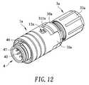
- the second embodimentis a circular rapid-joint connector comprised at least of a sliding bush 1a, an elastic element 2, a holding unit 3a and a connector plug 4.
- the sliding bush 1ahas multiple extension sections 10a provided on an end thereof; the extension sections 10a have a respective recession area 101a formed therebetween; and the inner edge of the sliding bush 1a is provided with a containing area 11a, and an end of the sliding bush 1a has multiple buckle holes 12a, while the inner edge of another end of the sliding bush 1a has a stop portion 13a.
- the elastic element 2is provided in the containing area 11a of the inner edge of the sliding bush 1a.
- the holding unit 3ais joined with the sliding bush 1a movably, the outer edge thereof having a limiting unit 30a capable of limiting each of the extension sections.
- the holding unit 3acomprises a sleeve 31a, a collar 32a provided in the sleeve 31a, a clip 34a provided outside of the collar 32a, and a locking bush 33a joined with the sleeve 31a and constricting the locking bush 33a of the clip 34a.
- the limiting unit 30ais provided on the outer edge of the sleeve 31a.
- the limiting unit 30acomprises bumps 301a mating with respective recession areas 101a.
- the bumps 301aare formed with a respective limiting slot 302a therebetween for each of the extension sections 10a to mate with.
- the outer edge of the sleeve 31ahas buckles 311a docked with respective buckle holes 12a, and the buckle holes 12a of the sliding bush 1a are larger than the buckles 311 a of the sleeve 31a.
- An end of the sleeve 31ahas multiple adjacent elastic pieces 312a.
- the inner surface of each of the elastic pieces 312ais provided with a stop ring 316a.
- the inner edge of the sleeve 31ais provided with a first internal thread portion 314a.
- the outer edge of the sleeve 31a adjacent to each of the elastic pieces 312ais provided with a first external thread portion 315a.
- An end of the clip 34ahas multiple adjacent clamping sheets 341a.
- An edge of the clip 34ais provided with a notch portion 342a.
- the inner edge of the locking bush 33ais provided with a second internal thread portion 331a joined with the first external thread portion 315a.
- the connector plug 4is penetrated into the sliding bush 1a and joined with the holding unit 3a, while an end of the connector plug 4 has a top portion 41, another end has a second external thread portion 42 joined with the first internal thread portion 314a, and the connector plug 4 is provided with multiple insertion terminals 43 therein.
- one side of the top portion 41is provided with an annular plate 44 abutting against the stop portion 13a, and the top portion 41 is provided with a ditch 45 thereon.
- the top portion 41is provided with a marking portion 46 thereon, and the connector plug 4 is provided with a guiding portion 47 therein.
- the elastic element 2may be disposed in the containing area 11a on the inner edge of the sliding bush 1a, and the buckle holes 12a of the sliding bush 1a are docked with the respective buckles 311a of the sleeve 31a, such that the extension sections 10a and the recession areas 101a of the sliding bush 1a are mated with the respective limiting slots 302a and the bumps 301a mutually.
- the buckle holes 12a of the sliding bush 1aare larger than the buckles 311a of the sleeve 31a, so that the sliding bush 1a is movable on the sleeve 31a.
- the sliding bush 1acan only move forwards or rearwards, but it cannot move leftwards, rightwards by fitting each of the extension sections 10a, the recession areas 101a, the limiting slot 302a and the bumps 301a.
- a wire 5is used to penetrate through the locking bush 33a, the clip 34a, the collar 32a, the sliding bush 1a and the sleeve 31a for the wire 5 to be connected with each of the insertion terminals 43 of the connector plug 4.
- the second external thread portion 42 of the connector plug 4is joined with the first internal thread portion 314a of the sleeve 31a, followed by providing the collar 32a between the elastic pieces 312a on an end of the sleeve 31a for the edge of the collar 32a to be locked by the stop ring 316a.
- the clip 34ais harnessed around the outer edge of the collar 32a.
- the locking bush 33ais joined with the first external thread portion 315a of the sleeve 31a by the second internal thread portion 331a thereof for the inner edge of the locking bush 33a to constrict the outer edge of the clip 34a.
- the clip 34atakes advantage of fitting between the clamping sheets 341a and the notch portion 342a to form a stable clamping force toward jacket of the wire 5 in order to prevent the wire 5 from escape.
- the clamping characteristic function of the clip 34amay be utilized in practical use, such that it is applicable to wires 5, 5a of different diameters.
- the locking bush 33ais locked more deeply in conjunction with the clip 34a(as shown in Figure 19A ).
- the locking bush 33ais locked shallower in conjunction with the clip 34a (as shown in Figure 19B ). As such, the assemblage is accomplished.
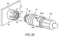
- FIGS 20 and 21are a schematic diagram showing operation of the invention, and a schematic diagram showing the invention after insertion with a connection socket.
- the second embodimentmay be inserted into a corresponding connection socket 6 in use, while correspond to the socket body 61 of the connection seat 6 by the connector plug 4 in docking, and correspond to the marking portion 63 of the connection socket 6 by the marking portion 46 of the connector plug 4, thereby the guiding portion 47 of the connector plug 4 corresponds to groove 62 of the connection socket 6 in order to identify insertion direction, such that incorrect insertion is avoided.
- each buckle 64 of the connection socket 6will withstand each buckle 64 of the connection socket 6 for each buckle 64 to be opened.
- an end of each buckle 64will abut against the end edge of the sliding bush 1a, such that the sliding bush 1a is pushed toward the holding unit 3a (rearwards) and compresses the elastic element 2, and be removed from the end edge of the sliding bush 1a after each buckle 64 enters the ditch 45 of the top portion 41, while the sliding bush 1a is pushed back toward the top portion 41 (forwards) automatically due to restitution force, such that the sliding bush 1a is locked on the outer edge of each buckle 64 of the connection socket 6 to limit each buckle 64 for each insertion terminal 43 to be inserted into the socket body 61, and thereby, to accomplish insertion operation.
- the sliding bush 1aIn disassembling, the sliding bush 1a is pulled toward the holding unit 3a (rearwards), such that the sliding bush 1a no longer locked to the outer edge of each buckle 64. After that, a force may be applied to disassemble the connector plug 4 from the connection socket 6 directly by the user.
- the sliding bush 1amoves forwards or rearwards, the sliding bush 1a is mated with the limiting slots 302a and bumps 301a by the respective extension sections 10a and recession areas 101a, such that the sliding bush 1a is capable of moving forwards or rearwards only, but it is incapable of rotating leftwards or rightwards during movement on the sleeve 31a to maintain its position of the sliding bush 1a accordingly for operation of use thereof to be more stable.
- the limiting unit 30a of the second embodimentmay be also of the structural type in this example, which differs in that the limiting unit 30b comprises a rib ring 303b provided on the sleeve 31a, on which multiple inserting slots 304b docked with the respective extension sections 10a are provided. Thereby, the extension sections 10a may be inserted into the respective inserting slots 304b while the sliding bush 1a moves forwards, rearwards.
- the sliding bush 1ais capable of moving forwards, rearwards only, but it is incapable of rotating leftwards, rightwards during movement on the sleeve 31a to maintain the position of the sliding bush 1a accordingly for operation of use thereof to be more stable.
- FIG. 23is a schematic diagram showing a further type of a limiting unit of the invention.
- the limiting units 30a, 30bmay also be of the structural type in this example, which differs in that the limiting unit 30c comprises multiple prolonged plates 305c mated with the respective recession areas 101a, and the prolonged plates 305c are formed with a respective groove 306c therebetween for each of the extension sections 10a to mate with.
- extension sections 10a and the recession areas 101amay be mated with the respective prolonged plates 305c and grooves 306c mutually when the sliding bush 1a moves forwards or rearwards, such that the sliding bush 1a is capable of moving forwards or rearwards only, but it is incapable of rotating leftwards or rightwards during movement on the sleeve 31a to maintain its position of the sliding bush 1a accordingly for operation of use thereof to be more stable.
- the clip 34a of the second embodimentmay be of the structural type in this example, which differs in that an end of the clip 34b has multiple adjacent clamping sheets 341b, and the structure of the notch portion 342a is omitted in this example.
- the inner edge of the locking bush 33amay also be used to constrict the outer edge of the clip 34b during operation, such that the clip 34b takes advantage of each of the clamping sheet 341b to form a stable clamping ability on the jacket of the wire 5, such that the applicability to wires of different diameters may also be achieved.
- the inventioncan achieve actually the expected objectives of the invention, such that in assembling, direct docking with the connection socket by the connector plug is available for the connection socket to push away the sliding bush.
- the sliding bushis pushed back by the elastic element automatically, such that the sliding bush is locked to the outer edge of the connection socket to complete operation of assemblage.
- the sliding bushis pulled backwards such that the sliding bush is not locked to the outer edge of the connection socket any more.
- a forcemay be applied to disassemble the connector plug from the connection socket directly, and the fitting of the extension sections, the recession areas and the limiting unit is utilized to limit and prevent the sliding bush from rotation.
Landscapes
- Details Of Connecting Devices For Male And Female Coupling (AREA)
Abstract
Description
- The invention is a circular rapid-joint connector, particularly relating to one which may be in direct docking with a connection socket by a connector plug when using, such that effects of rapid joint, solid joining, rapid disassembling, simple structure and facile of use are accomplished.
- Conventionally, the "Circular Connector", U.S. patent
US 6,517,373 B2 , includes a first connector element and a second connector element each of which has a first contact inset or a respective second contact inset in which, around the first contact inset of the first connector element, a sleeve-shaped latch segment is arranged from which, running along the longitudinal direction of the connector, one or more resilient latch flanges with latch tabs are formed that are appropriate for locking onto a ring-shaped groove formed on the inner side of the second connector element (locking position) and in which the first connector element includes an outer directly manually operated sleeve-shaped actuation slide, which can be slid back against a spring force along the longitudinal direction of the connector (unlocking position) and is adapted to actuate one or more sliding supports as locking elements, which can be slid along the longitudinal direction of the connector under a section of the latch flanges and are appropriate for supporting the latch flanges (locking position), characterized in that the latch flanges formed from the latch segment are integrally fixed to an end thereof in a manner ending rearwardly toward the actuation slide, that the sliding supports are formed from an end of the actuation slide and are directed directly toward the free ends of the latch segments, wherein the sliding supports extend from outside of the latch flanges essentially beneath their free ends only, when the actuation slide is pushed forward under the force of the spring. - From the cited patent described above, after the plug and the socket are docked, the actuation slide has to be pushed further in order for inserting the sliding supports beneath the latch flanges, such that the latch tabs are pushed and fastened into the ring-shaped groove, so that the operation of insertion and latching may be accomplished. As a result, cumbersome insertion procedure and complex structure will inhibit rapid connection in use of the conventional connector.
- In view of this, the inventor has researched and developed a circular rapid-joint connector in order to improve the above conventional connector with respect to various shortages thereof.
- For a major objective of the invention, in assembling, direct docking with the corresponding connection socket by the connector plug is available for the connection socket to push away the sliding bush. After the connection socket and the connector plug are snap-fitting, the sliding bush is pushed back by the elastic element automatically, such that the sliding bush is locked to the outer edge of the connection socket to complete action of assemblage. In disassembling, the sliding bush is pulled backwards such that the sliding bush is not limited to the outer edge of the connection socket any more. After that, a force may be applied to remove the connector plug from the connection socket directly, so that the effects of rapid assembling, solid joining, rapid disassembling, simple structure and facile of use are accomplished.
- In order to achieve the objective described above, the invention is a circular rapid-joint connector including: a sliding bush; an elastic element provided on the inner edge of the sliding bush; a holding unit joined with the sliding bush movably; and a connector plug penetrating into the sliding bush and joined with the holding unit.
- In the first embodiment described above, a containing area capable of accommodating the elastic element is provided on the inner edge of the sliding bush, an end of the sliding bush has multiple buckle holes engaged with the holding unit, and the inner edge of another end of the sliding bush has a stop portion abutting against the connector plug.
- In the first embodiment described above, the holding unit comprises a sleeve, a collar provided in the sleeve, and a locking bush joined with the sleeve.
- In the first embodiment described above, the outer edge of the sleeve has multiple buckles docking with the buckle holes respectively, and an end of the sleeve has multiple adjacent elastic pieces, the inner surface of each of the elastic pieces being provided with a respective sticking point, while the periphery of the collar is provided with a slot docking with each of the sticking points, and the inner edge of the sleeve is provided with a first internal thread portion joined with the connector plug, moreover, a first external thread portion is provided on the outer edge of the sleeve where each of the elastic pieces is adjacent thereto, while the inner edge of the locking bush is provided with a second internal thread portion joined with the first external thread portion.
- In the first embodiment described above, an end of the connector body has a top portion, another end has a second external thread portion joined with the first internal thread portion, and the connector plug is provided with multiple insertion terminals therein, while one side of the top portion is provided with an annular plate abutting against the stop portion, and the top portion is provided with a ditch thereon annularly.
- In the first embodiment described above, the top portion is provided with a marking portion thereon, and the connector plug is provided with a guiding portion therein.
- Another objective of the invention is that, in assembling, direct docking with a corresponding connection socket by a connector plug is available for the connection socket to push away a sliding bush. After the connection socket and the connector plug are snap-fitting, the sliding bush is pushed back by an elastic element automatically, such that the sliding bush is locked in the outer edge of the connection socket to complete action of assemblage. In disassembling, the sliding bush is pulled backwards such that the sliding bush is not limited in the outer edge of the connection socket any more. After that, a force may be applied to remove the connector plug from the connection socket directly, and the fitting of the extension sections, the recession areas and the limiting unit may result for the sliding bush to be locked without rotation, so that the effects of being capable of rapid assembling, solid joining, rapid disassembling, simple structure and facile of use are accomplished.
- In order to achieve the above objectives, the invention is a circular rapid-joint connector, which includes: a sliding bush with multiple extension sections and recession areas provided on an end thereof; an elastic element provided on the inner edge of the sliding bush; a holding unit joined with the sliding bush movably, the outer edge thereof having a limiting unit capable of limiting each of the extension sections; and a connector plug penetrating into the sliding bush and joined with the holding unit.
- In the second embodiment described above, a containing area capable of accommodating the elastic element is provided on the inner edge of the sliding bush, an end of the sliding bush has multiple buckle holes engaged with the holding unit, and the inner edge of another end of the sliding bush has a stop portion abutting against the connector plug.
- In the second embodiment described above, the holding unit comprises a sleeve, a collar provided in the sleeve, a clip provided outside of the collar, and a locking bush joining with the sleeve and constricting the clip, while the limiting unit is provided on the outer edge of the sleeve.
- In the second embodiment described above, the limiting unit comprises multiple bumps, each of which mates with the respective recession area, and the bumps are formed with a respective limiting slot therebetween for each of the extension sections to mate with.
- In the second embodiment described above, the limiting unit comprises a rib ring provided on the sleeve, and multiple insertion slots which are docked with the respective extension sections are provided thereon.
- In the second embodiment described above, the limiting unit comprises multiple prolonged plates, each of which mates with the respective recession area, and the prolonged plates are formed with a respective groove therebetween for each of the extension sections to mate with.
- In the second embodiment described above, an end of the clip has multiple adjacent clamping sheets.
- In the second embodiment described above, the edge of the clip has a notch portion.
- In the second embodiment described above, the outer edge of the sleeve has buckles docking with the buckle holes respectively, and an end of the sleeve has multiple adjacent elastic pieces, the inner surface of each of the elastic pieces being provided with a stop ring, and the inner edge of the sleeve is provided with a first internal thread portion joined with the connector plug, moreover, a first external thread portion is provided on the outer edge of the sleeve where each of the elastic pieces is adjacent thereto, while the inner edge of the locking bush is provided with a second internal thread portion joined with the first external thread portion.
- In the second embodiment described above, an end of the connector plug has a top portion, another end has a second external thread portion joined with the first internal thread portion, and the connector plug is provided with multiple insertion terminals therein, while one side of the top portion is provided with an annular plate abutting against the stop portion, and the top portion is provided with a ditch thereon annularly.
- In the second embodiment described above, the top portion is provided with a marking portion thereon, and the connector plug is provided with a guiding portion therein.
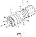
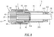
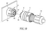
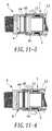
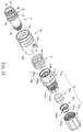
Figure 1 is a schematic diagram showing the appearance of the first embodiment.Figure 2 is an exploded schematic diagram showing elements of the first embodiment.Figure 3 is another exploded schematic diagram showing elements of the first embodiment.Figure 4 is a schematic diagram showing a cross section of the first embodiment.Figures 5 to 9 are schematic diagrams showing assemblage of the first embodiment.Figure 10 is a schematic diagram showing operation of the first embodiment.Figures 11-1 to 11-4 are schematic diagrams showing actions of assemblage and disassemblage of the first embodiment.Figure 12 is a schematic diagram showing the appearance of the second embodiment.Figure 13 is an exploded schematic diagram showing elements of second embodiment.Figure 14 is another exploded schematic diagram showing elements of the second embodiment.Figure 15 is a schematic diagram showing a cross section of the second embodiment.Figures 16 to 19A are schematic diagrams showing assemblage of the second embodiment.Figure 19B is a schematic diagram showing another assemblage of the second embodiment.Figure 20 is a schematic diagram showing usage of the second embodiment.Figure 21 is a schematic diagram showing the second embodiment after insertion with a connection socket.Figure 22 is a schematic diagram showing another type of the limiting unit of the second embodiment.Figure 23 is a schematic diagram showing a further type of the limiting unit of the second embodiment.Figure 24 is a schematic diagram showing another type of the clip of the second embodiment.- For thorough understanding of objectives, features and effects of the invention, the invention is described in detail as following in conjunction with attached drawings by means of embodiments.
- Refer to
Figures 1 ,2 ,3 and4 , which are a schematic diagram showing appearance of the invention, an exploded schematic diagram showing elements of the invention, another exploded schematic diagram showing elements of the invention, and a schematic diagram showing a cross section of the invention, respectively. As shown in the figures, the first embodiment is a circular rapid-joint connector comprised at least of a slidingbush 1, anelastic element 2, aholding unit 3 and aconnector plug 4. - The inner edge of the sliding
bush 1 is provided with a containingarea 11, and an end of thesliding bush 1 hasmultiple buckle holes 12 while the inner edge of another end of the slidingbush 1 has astop portion 13. - The
elastic element 2 is disposed in the containingarea 11 of the inner edge of the slidingbush 1. - The
holding unit 3 is joined with the slidingbush 1 movably. Moreover, theholding unit 3 comprises asleeve 31, acollar 32 provided in thesleeve 31, and alocking bush 33 joined with thesleeve 31, wherein the outer edge of thesleeve 31 hasbuckles 311 docked withrespective buckle holes 12. Furthermore, thebuckle holes 12 of the slidingbush 1 are larger than thebuckles 311 of thesleeve 31, and an end of thesleeve 31 has multiple adjacentelastic pieces 312, the inner surface of each of theelastic pieces 312 is provided with arespective sticking point 313, while the periphery of thecollar 32 is provided with aslot 321 docked with eachsticking point 314, and the inner edge of thesleeve 31 is provided with a firstinternal thread portion 314. In addition, a firstexternal thread portion 315 is provided on the outer edge of thesleeve 31 where each of theelastic pieces 312 is adjacent thereto, while the inner edge of thelocking bush 33 is provided with a secondinternal thread portion 331 joined with the firstexternal thread portion 315. - The
connector plug 4 is penetrated into the slidingbush 1 and joined with theholding unit 3, while an end of theconnector plug 4 has atop portion 41, another end has a secondexternal thread portion 42 joined with the firstinternal thread portion 314, and theconnector plug 4 is provided withmultiple insertion terminals 43 therein. Moreover, one side of thetop portion 41 is provided with anannular plate 44 abutting against thestop portion 13, and thetop portion 41 is provided with aditch 45 thereon. In addition, thetop portion 41 is provided with amarking portion 46 thereon, and theconnector plug 4 is provided with a guidingportion 47 therein. - Refer to
Figures 5, 6 ,7 ,8 and9 , which are schematic diagrams showing assemblage of the first embodiment. As shown in the figures, in assembling for the invention, theelastic element 2 may be disposed in the containingarea 11 of the inner edge of the slidingbush 1, followed by disposing thecollar 32 between an end of thesleeve 31 and eachelastic piece 312 for thecollar 32 to be docked with thesticking points 313 of the inner surface of eachelastic piece 312 by theslot 321 mutually, and docked with the respective buckle holes 12 of the slidingbush 1 by thebuckles 311. The buckle holes 12 of the slidingbush 1 are larger than thebuckles 311 of thesleeve 31, so that the slidingbush 1 may slide on thesleeve 31. After that, awire 5 is used to penetrate through the lockingbush 33, the slidingbush 1 and thesleeve 31, thewire 5 is connected with eachinsertion terminal 43 of theconnector plug 4, the secondexternal thread portion 42 of theconnector plug 4 is joined with the firstinternal thread portion 314 of thesleeve 31, and at last, the lockingbush 33 is joined with the firstexternal thread portion 315 of thesleeve 31 by the secondinternal thread portion 331 thereof. As such, the assemblage is accomplished. - Refer to
Figure 10 andFigures 11-1 to 11-4 , which are a schematic diagram showing operation of the invention and schematic diagrams showing actions of assemblage and disassemblage of the invention. As shown in the figures, the invention may be inserted to acorresponding connection socket 6 in use, while a user may correspond to thesocket body 61 of theconnection socket 6 by theconnector plug 4 in docking, and correspond to the markingportion 63 of theconnection socket 6 by the markingportion 46 of theconnector plug 4, thereby the guidingportion 47 of theconnector plug 4 corresponds to groove 62 of theconnection socket 6 in order to identify insertion direction, such that incorrect insertion is avoided. As thetop portion 41 of theconnector plug 4 is docked to thesocket body 61, the periphery of thetop portion 41 will withstand eachbuckle 64 of theconnection socket 6 for eachbuckle 64 to be opened. In the mean time, an end of eachbuckle 64 will abut against the end edge of the slidingbush 1, such that the slidingbush 1 is pushed toward the holding unit 3 (rearwards) and compresses theelastic element 2, and be removed from the end edge of the slidingbush 1 after eachbuckle 64 enters theditch 45 of thetop portion 41, while the slidingbush 1 is pushed back toward the top portion 41 (forwards) automatically due to restitution force, such that the slidingbush 1 is locked on the outer edge of eachbuckle 64 of theconnection socket 6 to limit eachbuckle 64 for eachinsertion terminal 43 to be inserted into thesocket body 61, and thereby, to accomplish insertion operation. - In disassembling, the sliding
bush 1 is pulled toward the holding unit 3 (rearwards), such that the slidingbush 1 is no longer locked to the outer edge of eachbuckle 64. After that, a force may be applied to remove theconnector plug 4 from theconnector plug 6 directly by the user. - In summary, with the description above, the invention can achieve actually the expected objectives of the invention, such that in assembling, direct docking with the connection socket by the connector plug is available for the connection socket to push away the sliding bush. After the connection socket and the connector plug are snap-fitting, the sliding bush is pushed back by the elastic element automatically, such that the sliding bush is locked to outer edge of the connection socket to complete operation of assemblage. In disassembling, the sliding bush is pulled backwards such that the sliding bush is not limited to the outer edge of the connection socket any more. After that, a force may be applied to remove the connector plug from the connection socket directly.
- Refer to
Figures 12 ,13 ,14 and15 , which are a schematic diagram showing appearance of the invention, an exploded schematic diagram showing elements of the invention, another exploded schematic diagram showing elements of the invention, and a schematic diagram showing a cross section of the invention, respectively. As shown in the figures, the second embodiment is a circular rapid-joint connector comprised at least of a sliding bush 1a, anelastic element 2, a holdingunit 3a and aconnector plug 4. - The sliding bush 1a has
multiple extension sections 10a provided on an end thereof; theextension sections 10a have arespective recession area 101a formed therebetween; and the inner edge of the sliding bush 1a is provided with a containingarea 11a, and an end of the sliding bush 1a hasmultiple buckle holes 12a, while the inner edge of another end of the sliding bush 1a has astop portion 13a. - The
elastic element 2 is provided in the containingarea 11a of the inner edge of the sliding bush 1a. - The holding
unit 3a is joined with the sliding bush 1a movably, the outer edge thereof having a limitingunit 30a capable of limiting each of the extension sections. The holdingunit 3a comprises asleeve 31a, acollar 32a provided in thesleeve 31a, aclip 34a provided outside of thecollar 32a, and a lockingbush 33a joined with thesleeve 31a and constricting the lockingbush 33a of theclip 34a. The limitingunit 30a is provided on the outer edge of thesleeve 31a. The limitingunit 30a comprisesbumps 301a mating withrespective recession areas 101a. Thebumps 301a are formed with a respective limitingslot 302a therebetween for each of theextension sections 10a to mate with. Wherein the outer edge of thesleeve 31a hasbuckles 311a docked withrespective buckle holes 12a, and the buckle holes 12a of the sliding bush 1a are larger than thebuckles 311 a of thesleeve 31a. An end of thesleeve 31a has multiple adjacentelastic pieces 312a. The inner surface of each of theelastic pieces 312a is provided with astop ring 316a. The inner edge of thesleeve 31a is provided with a firstinternal thread portion 314a. Furthermore, the outer edge of thesleeve 31a adjacent to each of theelastic pieces 312a is provided with a firstexternal thread portion 315a. An end of theclip 34a has multipleadjacent clamping sheets 341a. An edge of theclip 34a is provided with anotch portion 342a. Moreover, the inner edge of the lockingbush 33a is provided with a secondinternal thread portion 331a joined with the firstexternal thread portion 315a. - The
connector plug 4 is penetrated into the sliding bush 1a and joined with the holdingunit 3a, while an end of theconnector plug 4 has atop portion 41, another end has a secondexternal thread portion 42 joined with the firstinternal thread portion 314a, and theconnector plug 4 is provided withmultiple insertion terminals 43 therein. Moreover, one side of thetop portion 41 is provided with anannular plate 44 abutting against thestop portion 13a, and thetop portion 41 is provided with aditch 45 thereon. In addition, thetop portion 41 is provided with a markingportion 46 thereon, and theconnector plug 4 is provided with a guidingportion 47 therein. - Refer to
Figures 16 ,17 ,18 ,19A and 19B , which are schematic diagrams showing assemblage of the invention and a schematic diagram showing another assemblage of the invention. As shown in the figures, in assemblage for the second embodiment, theelastic element 2 may be disposed in the containingarea 11a on the inner edge of the sliding bush 1a, and the buckle holes 12a of the sliding bush 1a are docked with therespective buckles 311a of thesleeve 31a, such that theextension sections 10a and therecession areas 101a of the sliding bush 1a are mated with the respective limitingslots 302a and thebumps 301a mutually. Moreover, the buckle holes 12a of the sliding bush 1a are larger than thebuckles 311a of thesleeve 31a, so that the sliding bush 1a is movable on thesleeve 31a. Moreover, the sliding bush 1a can only move forwards or rearwards, but it cannot move leftwards, rightwards by fitting each of theextension sections 10a, therecession areas 101a, the limitingslot 302a and thebumps 301a. After that, awire 5 is used to penetrate through the lockingbush 33a, theclip 34a, thecollar 32a, the sliding bush 1a and thesleeve 31a for thewire 5 to be connected with each of theinsertion terminals 43 of theconnector plug 4. Then, the secondexternal thread portion 42 of theconnector plug 4 is joined with the firstinternal thread portion 314a of thesleeve 31a, followed by providing thecollar 32a between theelastic pieces 312a on an end of thesleeve 31a for the edge of thecollar 32a to be locked by thestop ring 316a. Subsequently, theclip 34a is harnessed around the outer edge of thecollar 32a. Finally, the lockingbush 33a is joined with the firstexternal thread portion 315a of thesleeve 31a by the secondinternal thread portion 331a thereof for the inner edge of the lockingbush 33a to constrict the outer edge of theclip 34a. In turn, theclip 34a takes advantage of fitting between the clampingsheets 341a and thenotch portion 342a to form a stable clamping force toward jacket of thewire 5 in order to prevent thewire 5 from escape. Moreover, the clamping characteristic function of theclip 34a may be utilized in practical use, such that it is applicable towires wire 5 of a wire diameter having larger diameter, the lockingbush 33a is locked more deeply in conjunction with theclip 34a(as shown inFigure 19A ). As it is applicable to thewire 5a of a wire diameter having smaller diameter, the lockingbush 33a is locked shallower in conjunction with theclip 34a (as shown inFigure 19B ). As such, the assemblage is accomplished. - Refer to
Figures 20 and21 , which are a schematic diagram showing operation of the invention, and a schematic diagram showing the invention after insertion with a connection socket. As shown in the figures, the second embodiment may be inserted into acorresponding connection socket 6 in use, while correspond to thesocket body 61 of theconnection seat 6 by theconnector plug 4 in docking, and correspond to the markingportion 63 of theconnection socket 6 by the markingportion 46 of theconnector plug 4, thereby the guidingportion 47 of theconnector plug 4 corresponds to groove 62 of theconnection socket 6 in order to identify insertion direction, such that incorrect insertion is avoided. As thetop portion 41 of theconnector plug 4 is docked tosocket body 61, the periphery of thetop portion 41 will withstand eachbuckle 64 of theconnection socket 6 for eachbuckle 64 to be opened. In the mean time, an end of eachbuckle 64 will abut against the end edge of the sliding bush 1a, such that the sliding bush 1a is pushed toward the holdingunit 3a (rearwards) and compresses theelastic element 2, and be removed from the end edge of the sliding bush 1a after eachbuckle 64 enters theditch 45 of thetop portion 41, while the sliding bush 1a is pushed back toward the top portion 41 (forwards) automatically due to restitution force, such that the sliding bush 1a is locked on the outer edge of eachbuckle 64 of theconnection socket 6 to limit eachbuckle 64 for eachinsertion terminal 43 to be inserted into thesocket body 61, and thereby, to accomplish insertion operation. - In disassembling, the sliding bush 1a is pulled toward the holding
unit 3a (rearwards), such that the sliding bush 1a no longer locked to the outer edge of eachbuckle 64. After that, a force may be applied to disassemble theconnector plug 4 from theconnection socket 6 directly by the user. - Moreover, as the sliding bush 1a moves forwards or rearwards, the sliding bush 1a is mated with the limiting
slots 302a andbumps 301a by therespective extension sections 10a andrecession areas 101a, such that the sliding bush 1a is capable of moving forwards or rearwards only, but it is incapable of rotating leftwards or rightwards during movement on thesleeve 31a to maintain its position of the sliding bush 1a accordingly for operation of use thereof to be more stable. - Refer to
Figure 22 , which is a schematic diagram showing another type of a limiting unit of the invention. As shown in the figure, in addition to the structure described above, the limitingunit 30a of the second embodiment may be also of the structural type in this example, which differs in that the limitingunit 30b comprises arib ring 303b provided on thesleeve 31a, on which multiple insertingslots 304b docked with therespective extension sections 10a are provided. Thereby, theextension sections 10a may be inserted into the respective insertingslots 304b while the sliding bush 1a moves forwards, rearwards. Therefore, the sliding bush 1a is capable of moving forwards, rearwards only, but it is incapable of rotating leftwards, rightwards during movement on thesleeve 31a to maintain the position of the sliding bush 1a accordingly for operation of use thereof to be more stable. - Refer to
Figure 23 , which is a schematic diagram showing a further type of a limiting unit of the invention. As shown in the figure, in addition to the structure described above, the limitingunits unit 30c comprises multipleprolonged plates 305c mated with therespective recession areas 101a, and theprolonged plates 305c are formed with arespective groove 306c therebetween for each of theextension sections 10a to mate with. Thereby, theextension sections 10a and therecession areas 101a may be mated with the respectiveprolonged plates 305c andgrooves 306c mutually when the sliding bush 1a moves forwards or rearwards, such that the sliding bush 1a is capable of moving forwards or rearwards only, but it is incapable of rotating leftwards or rightwards during movement on thesleeve 31a to maintain its position of the sliding bush 1a accordingly for operation of use thereof to be more stable. - Refer to
Figure 24 , which is a schematic diagram showing another type of a clip of the invention. As shown in the figure, in addition to the structure described above, theclip 34a of the second embodiment may be of the structural type in this example, which differs in that an end of theclip 34b has multipleadjacent clamping sheets 341b, and the structure of thenotch portion 342a is omitted in this example. However, the inner edge of the lockingbush 33a may also be used to constrict the outer edge of theclip 34b during operation, such that theclip 34b takes advantage of each of theclamping sheet 341b to form a stable clamping ability on the jacket of thewire 5, such that the applicability to wires of different diameters may also be achieved. - In summary, with the description above, the invention can achieve actually the expected objectives of the invention, such that in assembling, direct docking with the connection socket by the connector plug is available for the connection socket to push away the sliding bush. After the connection socket and the connector plug are snap-fitting, the sliding bush is pushed back by the elastic element automatically, such that the sliding bush is locked to the outer edge of the connection socket to complete operation of assemblage. In disassembling, the sliding bush is pulled backwards such that the sliding bush is not locked to the outer edge of the connection socket any more. After that, a force may be applied to disassemble the connector plug from the connection socket directly, and the fitting of the extension sections, the recession areas and the limiting unit is utilized to limit and prevent the sliding bush from rotation. As a result, the effects of rapid assembling, solid joining, rapid disassembling, simple structure and ease of use are achieved.
- While the description above are only preferred embodiments of the invention. Any equivalent modification made within the scope of claims of the invention shall be within the substantial scope of the invention.
Claims (12)
- A circular rapid-joint connector, including:a sliding bush;an elastic element provided on the inner edge of the sliding bush;a holding unit joined with the sliding bush movably; anda connector plug penetrating into the sliding bush and joined with the holding unit.
- The circular rapid-joint connector as described in claim 1, wherein a containing area capable of accommodating elastic element is provided on the inner edge of the sliding bush, an end of the sliding bush has multiple buckle holes engaged with the holding unit, and the inner edge of another end of the sliding bush has a stop portion abutting against the connector plug.
- The circular rapid-joint connector as described in claim 1, wherein the holding unit comprises a sleeve, a collar provided in the sleeve, and a locking bush joined with the sleeve, and the outer edge of the sleeve has multiple buckles docking with the buckle holes respectively, and an end of the sleeve has multiple adjacent elastic pieces, the inner surface of each of the elastic pieces being provided with a respective sticking point, while the periphery of the collar is provided with a slot docking with each of the sticking points, and the inner edge of the sleeve is provided with a first internal thread portion joined with the connector plug, moreover, a first external thread portion is provided on the outer edge of the sleeve where each of the elastic pieces is adjacent thereto, while the inner edge of the locking bush is provided with a second internal thread portion joined with the first external thread portion, and the buckle holes of the sliding bush are larger than the buckles of the sleeve.
- The circular rapid-joint connector as described in claim 1, wherein an end of the connector plug has a top portion, another end has a second external thread portion joined with the first internal thread portion, and the connector plug is provided with multiple insertion terminals therein, while one side of the top portion is provided with an annular plate abutting against the stop portion, and the top portion is provided with a ditch thereon annularly, moreover, the top portion is provided with a marking portion thereon, and the connector plug is provided with a guiding portion therein.
- A circular rapid-joint connector, including:a sliding bush with multiple extension sections provided on an end thereof, the extension sections being formed with a respective recession area therebetween;an elastic element provided on the inner edge of the sliding bush;a holding unit joined with the sliding bush movably, the outer edge thereof having a limiting unit capable of limiting each of the extension sections; anda connector plug penetrating into the sliding bush and joined with the holding unit.
- The circular rapid-joint connector as described in claim 5, wherein a containing area capable of accommodating the elastic element is provided on the inner edge of the sliding bush, an end of the sliding bush has multiple buckle holes engaged with the holding unit, and the inner edge of another end of the sliding bush has a stop portion abutting against the connector plug.
- The circular rapid-joint connector as described in claim 5, wherein the holding unit comprises a sleeve, a collar provided in the sleeve, a clip provided outside of the collar, and a locking bush joining with the sleeve and constricting the clip, while the limiting unit is provided on the outer edge of the sleeve, moreover, the outer edge of the sleeve has multiple buckles docking with the buckle holes respectively, and an end of the sleeve has multiple adjacent elastic pieces, the inner surface of each of the elastic pieces being provided with a stop ring, and the inner edge of the sleeve is provided with a first internal thread portion joined with the connector plug, moreover, a first external thread portion is provided on the outer edge of the sleeve where each of the elastic pieces is adjacent thereto, while the inner edge of the locking bush is provided with a second internal thread portion joined with the first external thread portion, and the buckle holes of the sliding bush are larger than the buckles of the sleeve.
- The circular rapid-joint connector as described in claim 7, wherein the limiting unit comprises multiple bumps, each of which mates with the respective recession area, and the bumps are formed with a respective limiting slot therebetween for each of the extension sections to mate with.
- The circular rapid-joint connector as described in claim 7, wherein the limiting unit comprises a rib ring provided on the sleeve, and multiple insertion slots which are docked with the respective extension sections are provided thereon.
- The circular rapid-joint connector as described in claim 7, wherein the limiting unit comprises multiple prolonged plates, each of which mates with the respective recession area, and the prolonged plates are formed with a respective groove therebetween for each of the extension sections to mate with.
- The circular rapid-joint connector as described in claim 7, wherein an end of the clip has multiple adjacent clamping sheets, and the edge of the clip has a notch portion, and an end of the clip has multiple adjacent clamping sheets.
- The circular rapid-joint connector as described in claim 5, wherein an end of the connector plug has a top portion, another end has a second external thread portion joined with the first internal thread portion, and the connector plug is provided with multiple insertion terminals therein, while one side of the top portion is provided with an annular plate abutting against the stop portion, and the top portion is provided with a ditch thereon annularly, moreover, the top portion is provided with a marking portion thereon, and the connector plug is provided with a guiding portion therein.
Applications Claiming Priority (2)
| Application Number | Priority Date | Filing Date | Title |
|---|---|---|---|
| TW104216558UTWM520748U (en) | 2015-10-16 | 2015-10-16 | Circular rapid connector |
| TW104219896UTWM523778U (en) | 2015-12-11 | 2015-12-11 | Improved structure of circular quick release connector |
Publications (2)
| Publication Number | Publication Date |
|---|---|
| EP3157105A1true EP3157105A1 (en) | 2017-04-19 |
| EP3157105B1 EP3157105B1 (en) | 2020-07-01 |
Family
ID=55027380
Family Applications (1)
| Application Number | Title | Priority Date | Filing Date |
|---|---|---|---|
| EP15201424.7AActiveEP3157105B1 (en) | 2015-10-16 | 2015-12-18 | Circular rapid-joint connector |
Country Status (1)
| Country | Link |
|---|---|
| EP (1) | EP3157105B1 (en) |
Cited By (3)
| Publication number | Priority date | Publication date | Assignee | Title |
|---|---|---|---|---|
| EP3531512A1 (en)* | 2017-12-11 | 2019-08-28 | Yamaichi Electronics Deutschland GmbH | Connector with clamping jaw |
| CN112072336A (en)* | 2020-08-26 | 2020-12-11 | 国网山东省电力公司电力科学研究院 | A kind of non-crimp connection fitting for wire connection and connection method |
| CN114340142A (en)* | 2021-12-29 | 2022-04-12 | 徐石文 | PCB convenient to connect |
Citations (5)
| Publication number | Priority date | Publication date | Assignee | Title |
|---|---|---|---|---|
| US4017139A (en)* | 1976-06-04 | 1977-04-12 | Sealectro Corporation | Positive locking electrical connector |
| WO1992008259A1 (en)* | 1990-10-31 | 1992-05-14 | Cm S.R.L. | A device for connecting a plug to a socket in coaxial connectors |
| US6464526B1 (en)* | 1997-09-10 | 2002-10-15 | Wieland Electric Gmbh | Electric plug and socket assembly |
| US6517373B2 (en) | 2000-05-02 | 2003-02-11 | Franz Binder Gmbh & Co. Elektrische Bauelemente Kg | Circular connector |
| DE102006040254A1 (en)* | 2006-08-28 | 2008-03-13 | Franz Binder Gmbh & Co Elektrische Bauelemente Kg | Round plug connector has two coupling element, detent element that has detent bars and contact support of former coupling element that are formed out of plastic material as section of single molded part |
Family Cites Families (2)
| Publication number | Priority date | Publication date | Assignee | Title |
|---|---|---|---|---|
| JPH04133373U (en)* | 1991-05-31 | 1992-12-11 | 第一電子工業株式会社 | electrical connectors |
| US7874860B2 (en)* | 2002-07-19 | 2011-01-25 | Phoenix Contact Gmbh & Co. Kg | Electrical connector |
- 2015
- 2015-12-18EPEP15201424.7Apatent/EP3157105B1/enactiveActive
Patent Citations (5)
| Publication number | Priority date | Publication date | Assignee | Title |
|---|---|---|---|---|
| US4017139A (en)* | 1976-06-04 | 1977-04-12 | Sealectro Corporation | Positive locking electrical connector |
| WO1992008259A1 (en)* | 1990-10-31 | 1992-05-14 | Cm S.R.L. | A device for connecting a plug to a socket in coaxial connectors |
| US6464526B1 (en)* | 1997-09-10 | 2002-10-15 | Wieland Electric Gmbh | Electric plug and socket assembly |
| US6517373B2 (en) | 2000-05-02 | 2003-02-11 | Franz Binder Gmbh & Co. Elektrische Bauelemente Kg | Circular connector |
| DE102006040254A1 (en)* | 2006-08-28 | 2008-03-13 | Franz Binder Gmbh & Co Elektrische Bauelemente Kg | Round plug connector has two coupling element, detent element that has detent bars and contact support of former coupling element that are formed out of plastic material as section of single molded part |
Cited By (4)
| Publication number | Priority date | Publication date | Assignee | Title |
|---|---|---|---|---|
| EP3531512A1 (en)* | 2017-12-11 | 2019-08-28 | Yamaichi Electronics Deutschland GmbH | Connector with clamping jaw |
| CN112072336A (en)* | 2020-08-26 | 2020-12-11 | 国网山东省电力公司电力科学研究院 | A kind of non-crimp connection fitting for wire connection and connection method |
| CN114340142A (en)* | 2021-12-29 | 2022-04-12 | 徐石文 | PCB convenient to connect |
| CN114340142B (en)* | 2021-12-29 | 2024-10-01 | 徐石文 | PCB board convenient to connect |
Also Published As
| Publication number | Publication date |
|---|---|
| EP3157105B1 (en) | 2020-07-01 |
Similar Documents
| Publication | Publication Date | Title |
|---|---|---|
| US9692174B1 (en) | Circular rapid joint connector | |
| US9570853B1 (en) | Circular rapid-joint connector | |
| US7322846B2 (en) | Quick connect connector | |
| CN102709744B (en) | Connector having locking mechanism | |
| EP2959174B1 (en) | Connector | |
| EP3157105A1 (en) | Circular rapid-joint connector | |
| TW201244290A (en) | Connector and connector unit | |
| US10986903B2 (en) | Walking stick | |
| EP1598903A3 (en) | Coaxial cable connector | |
| JP2008530754A (en) | Snap lock connection terminal | |
| JP2009268763A (en) | Operation section of treatment instrument for endoscope | |
| JP6875599B2 (en) | Electrical connector parts with locking elements | |
| US10994390B2 (en) | Push button pin for pliers | |
| EP2940361A2 (en) | Locking and ratcheting connector | |
| US20180280625A1 (en) | Apparatus for unsheathing and resheathing a needle device | |
| US4907981A (en) | Quick-release electrical connector coupling device | |
| KR101472703B1 (en) | Connector | |
| JP2016009589A (en) | Retaining connector | |
| CN100479265C (en) | Connecting device for conductive contact and handle of electric connector | |
| TWI291913B (en) | ||
| JP2006147272A (en) | Connection structure of coaxial connector and attachment sleeve used for the same | |
| CN211295479U (en) | Pull type connector | |
| JP6078992B2 (en) | Syringe | |
| US20080085631A1 (en) | Compression Ring For Coaxial Cable Connector | |
| CN111564724A (en) | Pull type connector |
Legal Events
| Date | Code | Title | Description |
|---|---|---|---|
| PUAI | Public reference made under article 153(3) epc to a published international application that has entered the european phase | Free format text:ORIGINAL CODE: 0009012 | |
| STAA | Information on the status of an ep patent application or granted ep patent | Free format text:STATUS: THE APPLICATION HAS BEEN PUBLISHED | |
| AK | Designated contracting states | Kind code of ref document:A1 Designated state(s):AL AT BE BG CH CY CZ DE DK EE ES FI FR GB GR HR HU IE IS IT LI LT LU LV MC MK MT NL NO PL PT RO RS SE SI SK SM TR | |
| AX | Request for extension of the european patent | Extension state:BA ME | |
| STAA | Information on the status of an ep patent application or granted ep patent | Free format text:STATUS: REQUEST FOR EXAMINATION WAS MADE | |
| 17P | Request for examination filed | Effective date:20170922 | |
| RBV | Designated contracting states (corrected) | Designated state(s):AL AT BE BG CH CY CZ DE DK EE ES FI FR GB GR HR HU IE IS IT LI LT LU LV MC MK MT NL NO PL PT RO RS SE SI SK SM TR | |
| STAA | Information on the status of an ep patent application or granted ep patent | Free format text:STATUS: EXAMINATION IS IN PROGRESS | |
| 17Q | First examination report despatched | Effective date:20180420 | |
| GRAP | Despatch of communication of intention to grant a patent | Free format text:ORIGINAL CODE: EPIDOSNIGR1 | |
| STAA | Information on the status of an ep patent application or granted ep patent | Free format text:STATUS: GRANT OF PATENT IS INTENDED | |
| INTG | Intention to grant announced | Effective date:20200109 | |
| GRAS | Grant fee paid | Free format text:ORIGINAL CODE: EPIDOSNIGR3 | |
| GRAA | (expected) grant | Free format text:ORIGINAL CODE: 0009210 | |
| STAA | Information on the status of an ep patent application or granted ep patent | Free format text:STATUS: THE PATENT HAS BEEN GRANTED | |
| AK | Designated contracting states | Kind code of ref document:B1 Designated state(s):AL AT BE BG CH CY CZ DE DK EE ES FI FR GB GR HR HU IE IS IT LI LT LU LV MC MK MT NL NO PL PT RO RS SE SI SK SM TR | |
| REG | Reference to a national code | Ref country code:AT Ref legal event code:REF Ref document number:1287027 Country of ref document:AT Kind code of ref document:T Effective date:20200715 Ref country code:CH Ref legal event code:EP | |
| REG | Reference to a national code | Ref country code:IE Ref legal event code:FG4D | |
| REG | Reference to a national code | Ref country code:DE Ref legal event code:R096 Ref document number:602015055011 Country of ref document:DE | |
| REG | Reference to a national code | Ref country code:LT Ref legal event code:MG4D | |
| PG25 | Lapsed in a contracting state [announced via postgrant information from national office to epo] | Ref country code:BG Free format text:LAPSE BECAUSE OF FAILURE TO SUBMIT A TRANSLATION OF THE DESCRIPTION OR TO PAY THE FEE WITHIN THE PRESCRIBED TIME-LIMIT Effective date:20201001 | |
| REG | Reference to a national code | Ref country code:NL Ref legal event code:MP Effective date:20200701 | |
| REG | Reference to a national code | Ref country code:AT Ref legal event code:MK05 Ref document number:1287027 Country of ref document:AT Kind code of ref document:T Effective date:20200701 | |
| PG25 | Lapsed in a contracting state [announced via postgrant information from national office to epo] | Ref country code:PT Free format text:LAPSE BECAUSE OF FAILURE TO SUBMIT A TRANSLATION OF THE DESCRIPTION OR TO PAY THE FEE WITHIN THE PRESCRIBED TIME-LIMIT Effective date:20201102 Ref country code:LT Free format text:LAPSE BECAUSE OF FAILURE TO SUBMIT A TRANSLATION OF THE DESCRIPTION OR TO PAY THE FEE WITHIN THE PRESCRIBED TIME-LIMIT Effective date:20200701 Ref country code:ES Free format text:LAPSE BECAUSE OF FAILURE TO SUBMIT A TRANSLATION OF THE DESCRIPTION OR TO PAY THE FEE WITHIN THE PRESCRIBED TIME-LIMIT Effective date:20200701 Ref country code:HR Free format text:LAPSE BECAUSE OF FAILURE TO SUBMIT A TRANSLATION OF THE DESCRIPTION OR TO PAY THE FEE WITHIN THE PRESCRIBED TIME-LIMIT Effective date:20200701 Ref country code:NO Free format text:LAPSE BECAUSE OF FAILURE TO SUBMIT A TRANSLATION OF THE DESCRIPTION OR TO PAY THE FEE WITHIN THE PRESCRIBED TIME-LIMIT Effective date:20201001 Ref country code:GR Free format text:LAPSE BECAUSE OF FAILURE TO SUBMIT A TRANSLATION OF THE DESCRIPTION OR TO PAY THE FEE WITHIN THE PRESCRIBED TIME-LIMIT Effective date:20201002 Ref country code:AT Free format text:LAPSE BECAUSE OF FAILURE TO SUBMIT A TRANSLATION OF THE DESCRIPTION OR TO PAY THE FEE WITHIN THE PRESCRIBED TIME-LIMIT Effective date:20200701 Ref country code:SE Free format text:LAPSE BECAUSE OF FAILURE TO SUBMIT A TRANSLATION OF THE DESCRIPTION OR TO PAY THE FEE WITHIN THE PRESCRIBED TIME-LIMIT Effective date:20200701 Ref country code:FI Free format text:LAPSE BECAUSE OF FAILURE TO SUBMIT A TRANSLATION OF THE DESCRIPTION OR TO PAY THE FEE WITHIN THE PRESCRIBED TIME-LIMIT Effective date:20200701 Ref country code:CZ Free format text:LAPSE BECAUSE OF FAILURE TO SUBMIT A TRANSLATION OF THE DESCRIPTION OR TO PAY THE FEE WITHIN THE PRESCRIBED TIME-LIMIT Effective date:20200701 | |
| PG25 | Lapsed in a contracting state [announced via postgrant information from national office to epo] | Ref country code:IS Free format text:LAPSE BECAUSE OF FAILURE TO SUBMIT A TRANSLATION OF THE DESCRIPTION OR TO PAY THE FEE WITHIN THE PRESCRIBED TIME-LIMIT Effective date:20201101 Ref country code:RS Free format text:LAPSE BECAUSE OF FAILURE TO SUBMIT A TRANSLATION OF THE DESCRIPTION OR TO PAY THE FEE WITHIN THE PRESCRIBED TIME-LIMIT Effective date:20200701 Ref country code:LV Free format text:LAPSE BECAUSE OF FAILURE TO SUBMIT A TRANSLATION OF THE DESCRIPTION OR TO PAY THE FEE WITHIN THE PRESCRIBED TIME-LIMIT Effective date:20200701 Ref country code:PL Free format text:LAPSE BECAUSE OF FAILURE TO SUBMIT A TRANSLATION OF THE DESCRIPTION OR TO PAY THE FEE WITHIN THE PRESCRIBED TIME-LIMIT Effective date:20200701 | |
| PG25 | Lapsed in a contracting state [announced via postgrant information from national office to epo] | Ref country code:NL Free format text:LAPSE BECAUSE OF FAILURE TO SUBMIT A TRANSLATION OF THE DESCRIPTION OR TO PAY THE FEE WITHIN THE PRESCRIBED TIME-LIMIT Effective date:20200701 | |
| REG | Reference to a national code | Ref country code:DE Ref legal event code:R097 Ref document number:602015055011 Country of ref document:DE | |
| PG25 | Lapsed in a contracting state [announced via postgrant information from national office to epo] | Ref country code:SM Free format text:LAPSE BECAUSE OF FAILURE TO SUBMIT A TRANSLATION OF THE DESCRIPTION OR TO PAY THE FEE WITHIN THE PRESCRIBED TIME-LIMIT Effective date:20200701 Ref country code:RO Free format text:LAPSE BECAUSE OF FAILURE TO SUBMIT A TRANSLATION OF THE DESCRIPTION OR TO PAY THE FEE WITHIN THE PRESCRIBED TIME-LIMIT Effective date:20200701 Ref country code:EE Free format text:LAPSE BECAUSE OF FAILURE TO SUBMIT A TRANSLATION OF THE DESCRIPTION OR TO PAY THE FEE WITHIN THE PRESCRIBED TIME-LIMIT Effective date:20200701 Ref country code:IT Free format text:LAPSE BECAUSE OF FAILURE TO SUBMIT A TRANSLATION OF THE DESCRIPTION OR TO PAY THE FEE WITHIN THE PRESCRIBED TIME-LIMIT Effective date:20200701 Ref country code:DK Free format text:LAPSE BECAUSE OF FAILURE TO SUBMIT A TRANSLATION OF THE DESCRIPTION OR TO PAY THE FEE WITHIN THE PRESCRIBED TIME-LIMIT Effective date:20200701 | |
| PLBE | No opposition filed within time limit | Free format text:ORIGINAL CODE: 0009261 | |
| STAA | Information on the status of an ep patent application or granted ep patent | Free format text:STATUS: NO OPPOSITION FILED WITHIN TIME LIMIT | |
| PG25 | Lapsed in a contracting state [announced via postgrant information from national office to epo] | Ref country code:AL Free format text:LAPSE BECAUSE OF FAILURE TO SUBMIT A TRANSLATION OF THE DESCRIPTION OR TO PAY THE FEE WITHIN THE PRESCRIBED TIME-LIMIT Effective date:20200701 | |
| 26N | No opposition filed | Effective date:20210406 | |
| PG25 | Lapsed in a contracting state [announced via postgrant information from national office to epo] | Ref country code:SK Free format text:LAPSE BECAUSE OF FAILURE TO SUBMIT A TRANSLATION OF THE DESCRIPTION OR TO PAY THE FEE WITHIN THE PRESCRIBED TIME-LIMIT Effective date:20200701 | |
| REG | Reference to a national code | Ref country code:CH Ref legal event code:PL | |
| PG25 | Lapsed in a contracting state [announced via postgrant information from national office to epo] | Ref country code:SI Free format text:LAPSE BECAUSE OF FAILURE TO SUBMIT A TRANSLATION OF THE DESCRIPTION OR TO PAY THE FEE WITHIN THE PRESCRIBED TIME-LIMIT Effective date:20200701 Ref country code:MC Free format text:LAPSE BECAUSE OF FAILURE TO SUBMIT A TRANSLATION OF THE DESCRIPTION OR TO PAY THE FEE WITHIN THE PRESCRIBED TIME-LIMIT Effective date:20200701 | |
| REG | Reference to a national code | Ref country code:BE Ref legal event code:MM Effective date:20201231 | |
| PG25 | Lapsed in a contracting state [announced via postgrant information from national office to epo] | Ref country code:IE Free format text:LAPSE BECAUSE OF NON-PAYMENT OF DUE FEES Effective date:20201218 Ref country code:LU Free format text:LAPSE BECAUSE OF NON-PAYMENT OF DUE FEES Effective date:20201218 | |
| PG25 | Lapsed in a contracting state [announced via postgrant information from national office to epo] | Ref country code:LI Free format text:LAPSE BECAUSE OF NON-PAYMENT OF DUE FEES Effective date:20201231 Ref country code:CH Free format text:LAPSE BECAUSE OF NON-PAYMENT OF DUE FEES Effective date:20201231 | |
| PG25 | Lapsed in a contracting state [announced via postgrant information from national office to epo] | Ref country code:TR Free format text:LAPSE BECAUSE OF FAILURE TO SUBMIT A TRANSLATION OF THE DESCRIPTION OR TO PAY THE FEE WITHIN THE PRESCRIBED TIME-LIMIT Effective date:20200701 Ref country code:MT Free format text:LAPSE BECAUSE OF FAILURE TO SUBMIT A TRANSLATION OF THE DESCRIPTION OR TO PAY THE FEE WITHIN THE PRESCRIBED TIME-LIMIT Effective date:20200701 Ref country code:CY Free format text:LAPSE BECAUSE OF FAILURE TO SUBMIT A TRANSLATION OF THE DESCRIPTION OR TO PAY THE FEE WITHIN THE PRESCRIBED TIME-LIMIT Effective date:20200701 | |
| PG25 | Lapsed in a contracting state [announced via postgrant information from national office to epo] | Ref country code:MK Free format text:LAPSE BECAUSE OF FAILURE TO SUBMIT A TRANSLATION OF THE DESCRIPTION OR TO PAY THE FEE WITHIN THE PRESCRIBED TIME-LIMIT Effective date:20200701 | |
| PG25 | Lapsed in a contracting state [announced via postgrant information from national office to epo] | Ref country code:BE Free format text:LAPSE BECAUSE OF NON-PAYMENT OF DUE FEES Effective date:20201231 | |
| PGFP | Annual fee paid to national office [announced via postgrant information from national office to epo] | Ref country code:DE Payment date:20241204 Year of fee payment:10 | |
| PGFP | Annual fee paid to national office [announced via postgrant information from national office to epo] | Ref country code:GB Payment date:20241230 Year of fee payment:10 | |
| PGFP | Annual fee paid to national office [announced via postgrant information from national office to epo] | Ref country code:FR Payment date:20241125 Year of fee payment:10 |