EP3155987A1 - Surgical stapler with progressively driven asymmetric alternating staple drivers - Google Patents
Surgical stapler with progressively driven asymmetric alternating staple driversDownload PDFInfo
- Publication number
- EP3155987A1 EP3155987A1EP16193980.6AEP16193980AEP3155987A1EP 3155987 A1EP3155987 A1EP 3155987A1EP 16193980 AEP16193980 AEP 16193980AEP 3155987 A1EP3155987 A1EP 3155987A1
- Authority
- EP
- European Patent Office
- Prior art keywords
- driver
- distal
- staple
- staples
- centerline
- Prior art date
- Legal status (The legal status is an assumption and is not a legal conclusion. Google has not performed a legal analysis and makes no representation as to the accuracy of the status listed.)
- Granted
Links
- 239000012636effectorSubstances0.000claimsabstractdescription114
- 230000000712assemblyEffects0.000claimsabstractdescription27
- 238000000429assemblyMethods0.000claimsabstractdescription27
- 230000033001locomotionEffects0.000claimsdescription11
- 230000015572biosynthetic processEffects0.000claimsdescription6
- 230000007704transitionEffects0.000claimsdescription2
- 230000001419dependent effectEffects0.000claims1
- 210000001519tissueAnatomy0.000description81
- 238000010304firingMethods0.000description31
- 238000000034methodMethods0.000description24
- 238000002271resectionMethods0.000description13
- 210000004185liverAnatomy0.000description12
- 210000005228liver tissueAnatomy0.000description11
- 239000010410layerSubstances0.000description8
- 238000013519translationMethods0.000description8
- 230000007246mechanismEffects0.000description7
- 230000004044responseEffects0.000description6
- 238000012986modificationMethods0.000description4
- 230000004048modificationEffects0.000description4
- 210000000056organAnatomy0.000description4
- 230000005855radiationEffects0.000description4
- 238000011282treatmentMethods0.000description4
- 238000004140cleaningMethods0.000description3
- 230000014509gene expressionEffects0.000description3
- 210000002767hepatic arteryAnatomy0.000description3
- 210000002989hepatic veinAnatomy0.000description3
- 238000003780insertionMethods0.000description3
- 230000037431insertionEffects0.000description3
- 238000009434installationMethods0.000description3
- 210000003240portal veinAnatomy0.000description3
- 125000006850spacer groupChemical group0.000description3
- 206010028980NeoplasmDiseases0.000description2
- 230000009471actionEffects0.000description2
- 230000008901benefitEffects0.000description2
- 230000005540biological transmissionEffects0.000description2
- 230000006835compressionEffects0.000description2
- 238000007906compressionMethods0.000description2
- 230000008569processEffects0.000description2
- 238000001356surgical procedureMethods0.000description2
- 210000000115thoracic cavityAnatomy0.000description2
- 210000003813thumbAnatomy0.000description2
- 230000000007visual effectEffects0.000description2
- 241000894006BacteriaSpecies0.000description1
- IAYPIBMASNFSPL-UHFFFAOYSA-NEthylene oxideChemical compoundC1CO1IAYPIBMASNFSPL-UHFFFAOYSA-N0.000description1
- 239000004775TyvekSubstances0.000description1
- 229920000690TyvekPolymers0.000description1
- 210000001015abdomenAnatomy0.000description1
- 230000006978adaptationEffects0.000description1
- 239000000853adhesiveSubstances0.000description1
- 230000001070adhesive effectEffects0.000description1
- 238000013459approachMethods0.000description1
- 230000000740bleeding effectEffects0.000description1
- 210000004204blood vesselAnatomy0.000description1
- 210000001124body fluidAnatomy0.000description1
- 230000008878couplingEffects0.000description1
- 238000010168coupling processMethods0.000description1
- 238000005859coupling reactionMethods0.000description1
- 238000002224dissectionMethods0.000description1
- 239000003814drugSubstances0.000description1
- 229940079593drugDrugs0.000description1
- 238000002651drug therapyMethods0.000description1
- 210000003811fingerAnatomy0.000description1
- 210000001035gastrointestinal tractAnatomy0.000description1
- 238000001415gene therapyMethods0.000description1
- 238000002955isolationMethods0.000description1
- 210000004072lungAnatomy0.000description1
- 239000000463materialSubstances0.000description1
- 238000002324minimally invasive surgeryMethods0.000description1
- 230000002980postoperative effectEffects0.000description1
- 230000002265preventionEffects0.000description1
- 238000011084recoveryMethods0.000description1
- 230000035945sensitivityEffects0.000description1
- 239000002356single layerSubstances0.000description1
- 230000001954sterilising effectEffects0.000description1
- 238000004659sterilization and disinfectionMethods0.000description1
- 230000001360synchronised effectEffects0.000description1
- 230000001225therapeutic effectEffects0.000description1
- 238000002604ultrasonographyMethods0.000description1
- 210000001835visceraAnatomy0.000description1
- 210000000707wristAnatomy0.000description1
Images


Classifications
- A—HUMAN NECESSITIES
- A61—MEDICAL OR VETERINARY SCIENCE; HYGIENE
- A61B—DIAGNOSIS; SURGERY; IDENTIFICATION
- A61B17/00—Surgical instruments, devices or methods
- A61B17/10—Surgical instruments, devices or methods for applying or removing wound clamps, e.g. containing only one clamp or staple; Wound clamp magazines
- A61B17/105—Wound clamp magazines
- A—HUMAN NECESSITIES
- A61—MEDICAL OR VETERINARY SCIENCE; HYGIENE
- A61B—DIAGNOSIS; SURGERY; IDENTIFICATION
- A61B17/00—Surgical instruments, devices or methods
- A61B17/068—Surgical staplers, e.g. containing multiple staples or clamps
- A61B17/072—Surgical staplers, e.g. containing multiple staples or clamps for applying a row of staples in a single action, e.g. the staples being applied simultaneously
- A61B17/07207—Surgical staplers, e.g. containing multiple staples or clamps for applying a row of staples in a single action, e.g. the staples being applied simultaneously the staples being applied sequentially
- A—HUMAN NECESSITIES
- A61—MEDICAL OR VETERINARY SCIENCE; HYGIENE
- A61B—DIAGNOSIS; SURGERY; IDENTIFICATION
- A61B17/00—Surgical instruments, devices or methods
- A61B17/068—Surgical staplers, e.g. containing multiple staples or clamps
- A—HUMAN NECESSITIES
- A61—MEDICAL OR VETERINARY SCIENCE; HYGIENE
- A61B—DIAGNOSIS; SURGERY; IDENTIFICATION
- A61B17/00—Surgical instruments, devices or methods
- A61B17/068—Surgical staplers, e.g. containing multiple staples or clamps
- A61B17/072—Surgical staplers, e.g. containing multiple staples or clamps for applying a row of staples in a single action, e.g. the staples being applied simultaneously
- A61B2017/07214—Stapler heads
- A61B2017/07228—Arrangement of the staples
- A—HUMAN NECESSITIES
- A61—MEDICAL OR VETERINARY SCIENCE; HYGIENE
- A61B—DIAGNOSIS; SURGERY; IDENTIFICATION
- A61B17/00—Surgical instruments, devices or methods
- A61B17/068—Surgical staplers, e.g. containing multiple staples or clamps
- A61B17/072—Surgical staplers, e.g. containing multiple staples or clamps for applying a row of staples in a single action, e.g. the staples being applied simultaneously
- A61B2017/07214—Stapler heads
- A61B2017/07271—Stapler heads characterised by its cartridge
- A—HUMAN NECESSITIES
- A61—MEDICAL OR VETERINARY SCIENCE; HYGIENE
- A61B—DIAGNOSIS; SURGERY; IDENTIFICATION
- A61B17/00—Surgical instruments, devices or methods
- A61B17/068—Surgical staplers, e.g. containing multiple staples or clamps
- A61B17/072—Surgical staplers, e.g. containing multiple staples or clamps for applying a row of staples in a single action, e.g. the staples being applied simultaneously
- A61B2017/07214—Stapler heads
- A61B2017/07278—Stapler heads characterised by its sled or its staple holder
- A—HUMAN NECESSITIES
- A61—MEDICAL OR VETERINARY SCIENCE; HYGIENE
- A61B—DIAGNOSIS; SURGERY; IDENTIFICATION
- A61B17/00—Surgical instruments, devices or methods
- A61B17/068—Surgical staplers, e.g. containing multiple staples or clamps
- A61B17/072—Surgical staplers, e.g. containing multiple staples or clamps for applying a row of staples in a single action, e.g. the staples being applied simultaneously
- A61B2017/07214—Stapler heads
- A61B2017/07285—Stapler heads characterised by its cutter
- A—HUMAN NECESSITIES
- A61—MEDICAL OR VETERINARY SCIENCE; HYGIENE
- A61B—DIAGNOSIS; SURGERY; IDENTIFICATION
- A61B90/00—Instruments, implements or accessories specially adapted for surgery or diagnosis and not covered by any of the groups A61B1/00 - A61B50/00, e.g. for luxation treatment or for protecting wound edges
- A61B90/08—Accessories or related features not otherwise provided for
- A61B2090/0807—Indication means
Definitions
- endoscopic surgical instrumentsmay be preferred over traditional open surgical devices since a smaller incision may reduce the post-operative recovery time and complications. Consequently, some endoscopic surgical instruments may be suitable for placement of a distal end effector at a desired surgical site through the cannula of a trocar. These distal end effectors may engage tissue in a number of ways to achieve a diagnostic or therapeutic effect (e.g., endocutter, grasper, cutter, stapler, clip applier, access device, drug/gene therapy delivery device, and energy delivery device using ultrasonic vibration, RF, laser, etc.). Endoscopic surgical instruments may include a shaft between the end effector and a handle portion, which is manipulated by the clinician.
- Such a shaftmay enable insertion to a desired depth and rotation about the longitudinal axis of the shaft, thereby facilitating positioning of the end effector within the patient. Positioning of an end effector may be further facilitated through inclusion of one or more articulation joints or features, enabling the end effector to be selectively articulated or otherwise deflected relative to the longitudinal axis of the shaft.
- endoscopic surgical instrumentsinclude surgical staplers. Some such staplers are operable to clamp down on layers of tissue, cut through the clamped layers of tissue, and drive staples through the layers of tissue to substantially seal the severed layers of tissue together near the severed ends of the tissue layers.
- surgical staplersare disclosed in U.S. Pat. No. 4,805,823 , entitled “Pocket Configuration for Internal Organ Staplers,” issued February 21, 1989; U.S. Pat. No. 5,415,334 , entitled “Surgical Stapler and Staple Cartridge,” issued May 16, 1995; U.S. Pat. No. 5,465,895 , entitled “Surgical Stapler Instrument,” issued November 14, 1995; U.S. Pat. No.
- surgical staplers referred to aboveare described as being used in endoscopic procedures, it should be understood that such surgical staplers may also be used in open procedures and/or other non-endoscopic procedures.
- a surgical staplermay be inserted through a thoracotomy, and thereby between a patient's ribs, to reach one or more organs in a thoracic surgical procedure that does not use a trocar as a conduit for the stapler.
- Such proceduresmay include the use of the stapler to sever and close a vessel leading to a lung. For instance, the vessels leading to an organ may be severed and closed by a stapler before removal of the organ from the thoracic cavity.
- surgical staplersmay be used in various other settings and procedures.
- 2014/0239042entitled “Integrated Tissue Positioning and Jaw Alignment Features for Surgical Stapler,” published August 28, 2014; U.S. Patent Pub. No. 2014/0239036 , entitled “Jaw Closure Feature for End Effector of Surgical Instrument,” published August 28, 2014; U.S. Patent Pub. No. 2014/0239040 , entitled “Surgical Instrument with Articulation Lock having a Detenting Binary Spring,” published August 28, 2014; U.S. Patent Pub. No. 2014/0239043 , entitled “Distal Tip Features for End Effector of Surgical Instrument,” published August 28, 2014; U.S. Patent Pub. No.
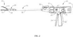
- FIG. 1depicts an exemplary surgical stapling and severing instrument (10) that includes a handle assembly (20), a shaft assembly (30), and an end effector (40).
- End effector (40) and the distal portion of shaft assembly (30)are sized for insertion, in a nonarticulated state as depicted in FIG. 1 , through a trocar cannula to a surgical site in a patient for performing a surgical procedure.
- a trocarmay be inserted in a patient's abdomen, between two of the patient's ribs, or elsewhere.
- instrument (10)is used without a trocar.
- end effector (40) and the distal portion of shaft assembly (30)may be inserted directly through a thoracotomy or other type of incision.
- terms such as “proximal” and “distal”are used herein with reference to a clinician gripping handle assembly (20) of instrument (10).
- end effector (40)is distal with respect to the more proximal handle assembly (20).
- spatial termssuch as “vertical” and “horizontal” are used herein with respect to the drawings.
- surgical instrumentsare used in many orientations and positions, and these terms are not intended to be limiting and absolute.
- handle assembly (20) of the present examplecomprises pistol grip (22), a closure trigger (24), and a firing trigger (26). Each trigger (24, 26) is selectively pivotable toward and away from pistol grip (22) as will be described in greater detail below.
- Handle assembly (20)further includes an anvil release button (25), a firing beam reverse switch (27), and a removable battery pack (28). These components will also be described in greater detail below.
- handle assembly (20)may have a variety of other components, features, and operabilities, in addition to or in lieu of any of those noted above.
- Other suitable configurations for handle assembly (20)will be apparent to those of ordinary skill in the art in view of the teachings herein.
- shaft assembly (30) of the present examplecomprises an outer closure tube (32), an articulation section (34), and a closure ring (36), which is further coupled with end effector (40).
- Closure tube (32)extends along the length of shaft assembly (30).
- Closure ring (36)is positioned distal to articulation section (34).
- Closure tube (32) and closure ring (36)are configured to translate longitudinally relative to handle assembly (20). Longitudinal translation of closure tube (32) is communicated to closure ring (36) via articulation section (34). Exemplary features that may be used to provide longitudinal translation of closure tube (32) and closure ring (36) will be described in greater detail below.
- Articulation section (34)is operable to laterally deflect closure ring (36) and end effector (40) laterally away from the longitudinal axis (LA) of shaft assembly (30) at a desired angle ( ⁇ ). End effector (40) may thereby reach behind an organ or approach tissue from a desired angle or for other reasons.
- articulation section (34)enables deflection of end effector (40) along a single plane.
- articulation section (34)enables deflection of end effector along more than one plane.
- articulationis controlled through an articulation control knob (35) which is located at the proximal end of shaft assembly (30).
- Knob (35)is rotatable about an axis that is perpendicular to the longitudinal axis (LA) of shaft assembly (30).
- Closure ring (36) and end effector (40)pivot about an axis that is perpendicular to the longitudinal axis (LA) of shaft assembly (30) in response to rotation of knob (35).
- rotation of knob (35) clockwisemay cause corresponding clockwise pivoting of closure ring (36) and end effector (40) at articulation section (34).
- Articulation section (34)is configured to communicate longitudinal translation of closure tube (32) to closure ring (36), regardless of whether articulation section (34) is in a straight configuration or an articulated configuration.
- articulation section (34) and/or articulation control knob (35)are/is constructed and operable in accordance with at least some of the teachings of U.S. Pub. No. 2014/0243801 , entitled “Surgical Instrument End Effector Articulation Drive with Pinion and Opposing Racks,” published August 28, 2014. Articulation section (34) may also be constructed and operable in accordance with at least some of the teachings of U.S. Pat. App. No. 14/314,125 , entitled “Articulation Drive Features for Surgical Stapler,” filed June 25, 2014; and/or in accordance with the various teachings below. Other suitable forms that articulation section (34) and articulation knob (35) may take will be apparent to those of ordinary skill in the art in view of the teachings herein.
- shaft assembly (30) of the present examplefurther includes a rotation knob (31).
- Rotation knob (31)is operable to rotate the entire shaft assembly (30) and end effector (40) relative to handle assembly (20) about the longitudinal axis (LA) of shaft assembly (30).
- rotation knob (31)is operable to selectively lock the angular position of shaft assembly (30) and end effector (40) relative to handle assembly (20) about the longitudinal axis (LA) of shaft assembly (30).
- rotation knob (31)may be translatable between a first longitudinal position, in which shaft assembly (30) and end effector (40) are rotatable relative to handle assembly (20) about the longitudinal axis (LA) of shaft assembly (30); and a second longitudinal position, in which shaft assembly (30) and end effector (40) are not rotatable relative to handle assembly (20) about the longitudinal axis (LA) of shaft assembly (30).
- shaft assembly (30)may have a variety of other components, features, and operabilities, in addition to or in lieu of any of those noted above.
- at least part of shaft assembly (30)is constructed in accordance with at least some of the teachings of U.S. Pub. No. 2014/0239038 , entitled "Surgical Instrument with Multi-Diameter Shaft,” published August 28, 2014.
- Other suitable configurations for shaft assembly (30)will be apparent to those of ordinary skill in the art in view of the teachings herein.
- end effector (40) of the present exampleincludes a lower jaw (50) and a pivotable anvil (60).
- Anvil (60)includes a pair of integral, outwardly extending pins (66) that are disposed in corresponding curved slots (54) of lower jaw (50).
- Anvil (60)is pivotable toward and away from lower jaw (50) between an open position (shown in FIGS. 2 and 4 ) and a closed position (shown in FIGS. 1 , 3 , and 7A-7B ).
- Use of the term "pivotable”(and similar terms with "pivot" as a base) should not be read as necessarily requiring pivotal movement about a fixed axis.
- anvil (60)pivots about an axis that is defined by pins (66), which slide along curved slots (54) of lower jaw (50) as anvil (60) moves toward lower jaw (50).
- the pivot axistranslates along the path defined by slots (54) while anvil (60) simultaneously pivots about that axis.
- the pivot axismay slide along slots (54) first, with anvil (60) then pivoting about the pivot axis after the pivot axis has slid a certain distance along the slots (54).
- pivotal movementis encompassed within terms such as “pivot,” “pivots,” “pivotal,” “pivotable,” “pivoting,” and the like.
- some versionsmay provide pivotal movement of anvil (60) about an axis that remains fixed and does not translate within a slot or channel, etc.
- lower jaw (50) of the present exampledefines a channel (52) that is configured to receive a staple cartridge (70).
- Staple cartridge (70)may be inserted into channel (52), end effector (40) may be actuated, and then staple cartridge (70) may be removed and replaced with another staple cartridge (70).
- Lower jaw (50)thus releasably retains staple cartridge (70) in alignment with anvil (60) for actuation of end effector (40).
- lower jaw (50)is constructed in accordance with at least some of the teachings of U.S. Pub. No. 2014/0239044 , entitled "Installation Features for Surgical Instrument End Effector Cartridge," published August 28, 2014. Other suitable forms that lower jaw (50) may take will be apparent to those of ordinary skill in the art in view of the teachings herein.
- staple cartridge (70) of the present examplecomprises a cartridge body (71) and a tray (76) secured to the underside of cartridge body (71).
- the upper side of cartridge body (71)presents a deck (73), against which tissue may be compressed when anvil (60) is in a closed position.
- Cartridge body (71)further defines a longitudinally extending channel (72) and a plurality of staple pockets (74).
- a staple (77)is positioned in each staple pocket (74).
- a staple driver (75)is also positioned in each staple pocket (74), underneath a corresponding staple (77), and above tray (76).
- staple drivers (75)are operable to translate upwardly in staple pockets (74) to thereby drive staples (77) upwardly through staple pockets (74) and into engagement with anvil (60).
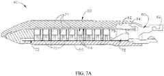
- Staple drivers (75)are driven upwardly by a wedge sled (78), which is captured between cartridge body (71) and tray (76), and which translates longitudinally through cartridge body (71).
- Wedge sled (78)includes a pair of obliquely angled cam surfaces (79), which are configured to engage staple drivers (75) and thereby drive staple drivers (75) upwardly as wedge sled (78) translates longitudinally through cartridge (70). For instance, when wedge sled (78) is in a proximal position as shown in FIG.
- staple drivers (75)are in downward positions and staples (77) are located in staple pockets (74).
- wedge sled (78)As wedge sled (78) is driven to the distal position shown in FIG. 7B by a translating knife member (80), wedge sled (78) drives staple drivers (75) upwardly, thereby driving staples (77) out of staple pockets (74) and into staple forming pockets (64).
- staple drivers (75)translate along a vertical dimension as wedge sled (78) translates along a horizontal dimension.
- staple cartridge (70)may be varied in numerous ways.
- staple cartridge (70) of the present exampleincludes two longitudinally extending rows of staple pockets (74) on one side of channel (72); and another set of two longitudinally extending rows of staple pockets (74) on the other side of channel (72).
- staple cartridge (70)includes three, one, or some other number of staple pockets (74) on each side of channel (72).
- staple cartridge (70)is constructed and operable in accordance with at least some of the teachings of U.S. Pub. No. 2014/0239042 , entitled "Integrated Tissue Positioning and Jaw Alignment Features for Surgical Stapler," published August 28, 2014.
- staple cartridge (70)may be constructed and operable in accordance with at least some of the teachings of U.S. Pub. No. 2014/0239044 , entitled “Installation Features for Surgical Instrument End Effector Cartridge,” published August 28, 2014.
- Other suitable forms that staple cartridge (70) may takewill be apparent to those of ordinary skill in the art in view of the teachings herein.
- anvil (60) of the present examplecomprises a longitudinally extending channel (62) and a plurality of staple forming pockets (64).
- Channel (62)is configured to align with channel (72) of staple cartridge (70) when anvil (60) is in a closed position.
- Each staple forming pocket (64)is positioned to lie over a corresponding staple pocket (74) of staple cartridge (70) when anvil (60) is in a closed position.
- Staple forming pockets (64)are configured to deform the legs of staples (77) when staples (77) are driven through tissue and into anvil (60).
- staple forming pockets (64)are configured to bend the legs of staples (77) to secure the formed staples (77) in the tissue.
- Anvil (60)may be constructed in accordance with at least some of the teachings of U.S. Pub. No. 2014/0239042 , entitled “Integrated Tissue Positioning and Jaw Alignment Features for Surgical Stapler,” published August 28, 2014; at least some of the teachings of U.S. Pub. No. 2014/0239036 , entitled “Jaw Closure Feature for End Effector of Surgical Instrument,” published August 28, 2014; and/or at least some of the teachings of U.S. Pub. No. 2014/0239037 , entitled “Staple Forming Features for Surgical Stapling Instrument,” published August 28, 2014.
- Other suitable forms that anvil (60) may takewill be apparent to those of ordinary skill in the art in view of the teachings herein.
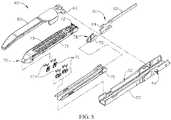
- knife member (80)is configured to translate through end effector (40). As best seen in FIGS. 5 and 7A-7B , knife member (80) is secured to the distal end of a firing beam (82), which extends through a portion of shaft assembly (30). As best seen in FIGS. 4 and 6 , knife member (80) is positioned in channels (62, 72) of anvil (60) and staple cartridge (70). Knife member (80) includes a distally presented cutting edge (84) that is configured to sever tissue that is compressed between anvil (60) and deck (73) of staple cartridge (70) as knife member (80) translates distally through end effector (40). As noted above and as shown in FIGS.
- knife member (80)also drives wedge sled (78) distally as knife member (80) translates distally through end effector (40), thereby driving staples (77) through tissue and against anvil (60) into formation.
- wedge sled (78)distally as knife member (80) translates distally through end effector (40), thereby driving staples (77) through tissue and against anvil (60) into formation.
- end effector (40)includes lockout features that are configured to prevent knife member (80) from advancing distally through end effector (40) when a staple cartridge (70) is not inserted in lower jaw (50).
- end effector (40)may include lockout features that are configured to prevent knife member (80) from advancing distally through end effector (40) when a staple cartridge (70) that has already been actuated once (e.g., with all staples (77) deployed therefrom) is inserted in lower jaw (50).
- lockout featuresmay be configured in accordance with at least some of the teachings of U.S. Pub. No.
- anvil (60)is driven toward lower jaw (50) by advancing closure ring (36) distally relative to end effector (40).
- Closure ring (36)cooperates with anvil (60) through a camming action to drive anvil (60) toward lower jaw (50) in response to distal translation of closure ring (36) relative to end effector (40).
- closure ring (36)may cooperate with anvil (60) to open anvil (60) away from lower jaw (50) in response to proximal translation of closure ring (36) relative to end effector (40).
- closure ring (36) and anvil (60)may interact in accordance with at least some of the teachings of U.S. Pub. No.
- handle assembly (20)includes pistol grip (22) and closure trigger (24).
- anvil (60)is closed toward lower jaw (50) in response to distal advancement of closure ring (36).
- closure trigger (24)is pivotable toward pistol grip (22) to drive closure tube (32) and closure ring (36) distally.
- suitable componentsthat may be used to convert pivotal movement of closure trigger (24) toward pistol grip (22) into distal translation of closure tube (32) and closure ring (36) relative to handle assembly (20) will be apparent to those of ordinary skill in the art in view of the teachings herein.
- closure trigger (24)When closure trigger (24) reaches a fully pivoted state, such that anvil (60) is in a fully closed position relative to lower jaw (50), locking features in handle assembly (20) lock the position of closure trigger (24) and closure tube (32), thereby locking anvil (60) in a fully closed position relative to lower jaw (50). These locking features are released by actuation of anvil release button (25).
- Anvil release button (25)is configured and positioned to be actuated by the thumb of the operator hand that grasps pistol grip (22).
- the operatormay grasp pistol grip (22) with one hand, actuate closure trigger (24) with one or more fingers of the same hand, and then actuate anvil release button (25) with the thumb of the same hand, without ever needing to release the grasp of pistol grip (22) with the same hand.
- closure trigger (24)with one or more fingers of the same hand
- anvil release button (25)with the thumb of the same hand
- Other suitable features that may be used to actuate anvil (60)will be apparent to those of ordinary skill in the art in view of the teachings herein.
- instrument (10)provides motorized control of firing beam (82).
- instrument (10)includes motorized components that are configured to drive firing beam (82) distally in response to pivoting of firing trigger (26) toward pistol grip (22).
- a motor(not shown) is contained in pistol grip (22) and receives power from battery pack (28). This motor is coupled with a transmission assembly (not shown) that converts rotary motion of a drive shaft of the motor into linear translation of firing beam (82).
- firing beam (82)may only be advanced distally when anvil (60) is in a fully closed position relative to lower jaw (50). After firing beam (82) is advanced distally to sever tissue and drive staples (77) as described above with reference to FIGS.
- the drive assembly for firing beam (82)may be automatically reversed to drive firing beam (82) proximally back to the retracted position (e.g., back from the position shown in FIG. 7B to the position shown in FIG. 7A ).
- the operatormay actuate firing beam reverse switch (27), which may reverse the drive assembly for firing beam (82) in order to retract firing beam (82) to a proximal position.
- Handle assembly (20) of the present examplefurther includes a bailout feature (21), which is operable to provide a mechanical bailout allowing the operator to manually retract firing beam (82) proximally (e.g., in the event of power loss while firing beam (82) is in a distal position, etc.).
- the features that are operable to provide motorized actuation of firing beam (82)may be configured and operable in accordance with at least some of the teachings of U.S. Pat. No. 8,210,411 , entitled “Motor-Driven Surgical Instrument,” issued July 3, 2012.
- the features that are operable to provide motorized actuation of firing beam (82)may be configured and operable in accordance with at least some of the teachings of U.S. Pat. No. 8,453,914 , entitled “Motor-Driven Surgical Cutting Instrument with Electric Actuator Directional Control Assembly,” issued June 4, 2013.
- the features that are operable to provide motorized actuation of firing beam (82)may be configured and operable in accordance with at least some of the teachings of U.S. Patent App. No. 14/226,142 , entitled “Surgical Instrument Comprising a Sensor System,” filed March 26, 2014.
- firing beam (82)may be manually actuated in accordance with at least some of the teachings of any other reference cited herein.
- FIG. 8shows end effector (40) having been actuated through a single stroke through tissue (90).
- cutting edge (84)obscured in FIG. 8
- staple drivers (75)have driven two alternating rows of staples (77) through the tissue (90) on each side of the cut line produced by cutting edge (84).
- Staples (77)are all oriented substantially parallel to the cut line in this example, though it should be understood that staples (77) may be positioned at any suitable orientations.
- end effector (40)is withdrawn from the trocar after the first stroke is complete, the spent staple cartridge (70) is replaced with a new staple cartridge (70), and end effector (40) is then again inserted through the trocar to reach the stapling site for further cutting and stapling. This process may be repeated until the desired amount of cuts and staples (77) have been provided.
- Anvil (60)may need to be closed to facilitate insertion and withdrawal through the trocar; and anvil (60) may need to be opened to facilitate replacement of staple cartridge (70).
- cutting edge (84)may cut tissue substantially contemporaneously with staples (77) being driven through tissue during each actuation stroke.
- cutting edge (84)just slightly lags behind driving of staples (77), such that staple (77) is driven through the tissue just before cutting edge (84) passes through the same region of tissue, though it should be understood that this order may be reversed or that cutting edge (84) may be directly synchronized with adjacent staples.
- FIG. 8shows end effector (40) being actuated in two layers (92, 94) of tissue (90), it should be understood that end effector (40) may be actuated through a single layer of tissue (90) or more than two layers (92, 94) of tissue.
- FIG. 8shows end effector (40) being actuated in two substantially flat, apposed planar layers (92, 94) of tissue, it should be understood that end effector (40) may also be actuated across a tubular structure such as a blood vessel, a section of the gastrointestinal tract, etc.
- FIG. 8should therefore not be viewed as demonstrating any limitation on the contemplated uses for end effector (40).
- instrument (10)may be used will be apparent to those of ordinary skill in the art in view of the teachings herein.
- instrument (10)may be configured and operable in accordance with any of the various references cited herein. Additional exemplary modifications that may be provided for instrument (10) will be described in greater detail below. Various suitable ways in which the below teachings may be incorporated into instrument (10) will be apparent to those of ordinary skill in the art. Similarly, various suitable ways in which the below teachings may be combined with various teachings of the references cited herein will be apparent to those of ordinary skill in the art. It should also be understood that the below teachings are not limited to instrument (10) or devices taught in the references cited herein. The below teachings may be readily applied to various other kinds of instruments, including instruments that would not be classified as surgical staplers. Various other suitable devices and settings in which the below teachings may be applied will be apparent to those of ordinary skill in the art in view of the teachings herein.
- a liverincludes tissue including vessels or ducts passing throughout.
- the resectionmay be anatomic (e.g., resection of the right or left side of the liver, inclusive of the lobes on that side) or non-anatomic (e.g., resection of just a single lobe or wedge of liver tissue).
- This resection processmay entail at least three kinds of steps - a first step to dissect the tissue (e.g., liver parenchyma) around the vessels or ducts, to thereby isolate or reveal the vessels or ducts; a second step to ligate those vessels or ducts; and a third step to sever the ligated vessels or ducts.
- tissuee.g., liver parenchyma
- liver resectionincludes the well known Kelly clamp method, where a Kelly style clamp is used to compress the liver tissue and thereby dissect the tissue through a crushing action.
- treatmentsmay require many instruments to accommodate such a wide variety of tissues and vessels or ducts within the human body, thereby adding to the time and complexity associated with assessing the state of the tissue, selecting and/or changing instruments, and performing the resection.
- Itmay therefore be desirable to provide a surgical instrument (410) with an end effector (412) having a pair of crush surfaces (414, 416) that are configured to sever tissue by crushing the tissue; while also providing an adjacent staple cartridge (418) to selectively ligate one or more vessels or ducts passing through the tissue.
- a single surgical instrument(210, 410) will allow the operator to more quickly assess the tissue and proceed with further tissue dissection and/or ligation of vessels and ducts.
- Surgical instruments (410)are described below in the context of dissecting liver tissue (e.g., liver parenchyma) with crush surfaces (414, 416) and using staples to ligate associated vessels or ducts (e.g., portal vein, hepatic vein branches, hepatic artery branches, extrahepatic vessels, etc.).
- associated vessels or ductse.g., portal vein, hepatic vein branches, hepatic artery branches, extrahepatic vessels, etc.
- the vessel or duct that is sealed by the staplesis exposed when the operator crushes the liver tissue with surfaces (414, 416).
- the vessel or duct that is sealed by the staplesis separate from the liver tissue that the operator has crushed with surfaces (414, 416).
- surgical instruments (410) and method of treatmentare provided in the context of liver resection, it will be appreciated that surgical instruments (410) may be alternatively configured to treat any tissue in the human body with similar features. It should also be understood that that the features discussed below may be readily incorporated into surgical instrument (10) discussed above. To this end, like numbers indicate like features described above in greater detail.
- end effectors (412)apply at least two laterally spaced apart rows of staples where the staples in one row have the same height as the staples in another row. In some variations, end effectors (412) are modified to apply at least two laterally spaced apart rows of staples where the staples in one row have a height that is different from the height of the staples in another row.
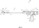
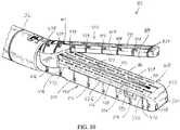
- FIGS. 9-13show surgical instrument (410) with end effector (412) having upper crush surface (414), lower crush surface (416), staple cartridge (418), and knife member (419).
- end effector (412)having crush surfaces (414, 416) that are configured to sever tissue by crushing the tissue; while also providing adjacent staple cartridge (418) to selectively ligate one or more vessels passing through the tissue.
- knife member (419)is configured to cut the one or more vessels for complete removal of the surrounding tissue.
- Surgical instrument (410) of the present examplealso includes handle assembly (20) and shaft assembly (30) discussed above in greater detail. Except as otherwise described below, end effector (412), in conjunction with handle assembly (20) and shaft assembly (30), is configured and operable similar to end effector (40) (see FIG. 1 ).
- end effector (412)may have a length of approximately 40 mm and a width of approximately 7mm. Alternatively, any other suitable dimension may be used.
- End effector (412) of the present exampleincludes a lower jaw (420) and an upper jaw (422), which forms an anvil (424).
- Upper jaw (422)is pivotally mounted relative to lower jaw (420) for receiving the tissue therebetween.
- anvil (424)is pivotable toward and away from lower jaw (420) between an open position and a closed position (e.g., in response to pivotal movement of trigger (24) toward and away from pistol grip (22)).
- anvil (424)pivots about an axis that is defined by pins (not shown), which slide along curved slots (not shown) of lower jaw (420) as anvil (424) moves toward lower jaw (420).
- the pivot axistranslates along the path defined by slots (not shown) while anvil (424) simultaneously pivots about that axis.
- the pivot axismay slide along slots (not shown) first, with anvil (424) then pivoting about the pivot axis after the pivot axis slides a certain distance along the slots (not shown).
- some versionsmay provide pivotal movement of anvil (424) about an axis that remains fixed and does not translate within a slot or channel, etc.
- lower jaw (420) of the present exampledefines a channel (426) that is configured to receive staple cartridge (418).
- Staple cartridge (418)may be inserted into channel (426), end effector (412) may be actuated, and then staple cartridge (418) may be removed and replaced with another staple cartridge (418).
- Lower jaw (420)thus releasably retains staple cartridge (418) in alignment with anvil (424) for actuation of end effector (412).
- the components of staple cartridge (418)are fully integrated into lower jaw (420) such that end effector (412) may only be used once.
- Other suitable forms that lower jaw (420) may takewill be apparent to those of ordinary skill in the art in view of the teachings herein.
- lower and upper jaws (420, 422)extend to a distal tip (432), which is further defined by staple cartridge (418).
- Staple cartridge (418) of the present examplecomprises a cartridge body (434) and a tray (436) ( see FIG. 19 ) secured to an underside of cartridge body (434).
- An upper side of cartridge body (434)presents a deck (438), against which tissue may be compressed when anvil (424) is in a closed position.
- lower crush surface (416)is positioned along staple cartridge (418).
- lower crush surface (416), as well as cooperating upper crush surface (414)may be alternatively positioned along end effector (412) for severing tissue via compression.
- Cartridge body (434)further defines an elongated channel (439) extending through lower jaw (420) and linearly along a centerline (440) of end effector (412).
- Another elongated channel (441) defined by anvil (424)extends through upper jaw (422) and linearly along centerline (440), as well, for reasons discussed below in greater detail.
- a plurality of staple pockets (442)follow a predetermined pattern along deck (438) on opposing sides of centerline (440).
- staple cartridge (418)includes two longitudinally extending rows of staple pockets (442) on one side of centerline (440); and another set of two longitudinally extending rows of staple pockets (442) on the other side of centerline (440).
- staple cartridge (418)may include three, one, or some other number of staple pockets (442) on each side of centerline (440).
- One of a plurality of staples (444)is positioned in respective staple pockets (442).
- Adjacent rows of staple pockets (442)are configured to overlap in a direction transverse to the centerline (440) in order to install the plurality of staples (444) within the tissue and inhibit openings therebetween for improved ligation.
- a consistent gap (G1)is maintained between adjacent staple pockets (442) for consistent overlap in the present example.
- overlapis intended to include one feature overlapping with another in at least one direction.
- a featuremay be offset from another feature and still overlap as described herein in the event that these features overlap in at least one plane, such as a transverse plane including the transverse direction.
- Other suitable forms that staple cartridge (418) may takewill be apparent to those of ordinary skill in the art in view of the teachings herein.
- anvil (424) of the present examplehas a plurality of staple forming pockets (446).
- Each staple forming pocket (446)is positioned to lie over a corresponding staple pocket (442) of staple cartridge (418) when anvil (424) is in a closed position.
- Staple forming pockets (446)are configured to deform each leg (448) of staples (444) when staples (444) are driven through tissue and into anvil (424).
- staple forming pockets (446)are configured to bend legs (448) of staples (444) to secure the formed staples (444) in the tissue.
- Other suitable forms that anvil (424) may takewill be apparent to those of ordinary skill in the art in view of the teachings herein.
- staple cartridge (418)includes staple drivers (452) positioned in staple pockets (442), underneath a corresponding staple (444), and above tray (436) ( see FIG. 19 ).
- staple drivers (452)are operable to translate upwardly in staple pockets (442) to thereby drive staples (444) upwardly through staple pockets (442) and into engagement with anvil (424).
- Staple drivers (452)are driven upwardly by a wedge sled (456), which is captured between cartridge body (434) and tray (436) ( see FIG. 19 ), and which translates longitudinally through cartridge body (434) along a pair of cam slots (457).
- Wedge sled (456)includes a cam ramp (258) having a leading cam surface (460), an intermediate cam surface (462), and a trailing cam surface (464).
- leading cam surface (460)may be angled at approximately 45° relative to a horizontal plane; and intermediate cam surface (462) may be angled at approximately 22° relative to a horizontal plane.
- Cam ramps (458)are generally configured to engage staple drivers (452) and thereby drive staple drivers (452) upwardly as wedge sled (456) translates longitudinally through staple cartridge (418) from a proximal sled position to a distal sled position.
- wedge sled (456)when wedge sled (456) is in the proximal sled position, staple drivers (452) are in downward positions and staples (444) are located in staple pockets (442).
- wedge sled (456)As wedge sled (456) is driven to the distal sled position by translating knife member (419), wedge sled (456) drives staple drivers (452) upwardly, thereby driving staples (444) out of staple pockets (442) and into staple forming pockets (446).
- staple drivers (452)translate along respective vertical planes as wedge sled (456) translates along a horizontal plane.
- knife member (419)is configured to translate through end effector (412). As best seen in FIG. 13 , knife member (419) is secured to a distal end of firing beam (82), which extends through a portion of shaft assembly (30). Knife member (80) is positioned in channels (439, 441) of staple cartridge (418) and anvil (424), respectively. Knife member (419) includes a distally presented cutting edge (468) that is configured to sever tissue that is compressed between anvil (424) and deck (438) of staple cartridge (418) as knife member (419) translates distally through end effector (412). As noted above, knife member (419) also drives wedge sled (456) distally as knife member (419) translates distally through end effector (412), thereby driving staples (444) through tissue and against anvil (424) into formation.
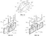
- FIGS. 13-16show wedge sled (456) and staple drivers (452), which are configured to direct staples (444) upwardly toward anvil (424) for forming staples (444) as described herein.
- Wedge sled (456)includes spacers (484) projecting from left and right sides of a central portion (485) thereof to a pair of left and right cam ramps (458). Spacers (484) are configured to center wedge sled (456) in a track slot (486) ( see FIG. 19 ) extending through staple cartridge (418) along centerline (440).
- Each cam ramp (458)projects upwardly from each respective spacer (484) to align each cam ramp (458) centrally within parallel linear cam slots (457) as wedge sled (456) slides from the proximal sled position to the distal sled position.
- a rear end portion (488)receives translating knife member (419), which is configured to translate toward distal tip (432), for directing the wedge sled (456) distally toward the distal position.
- a driver assembly (492)includes three staple drivers (452) connected by a driver cam (494) extending therebetween.
- driver assembly (492)may also be referred to as triple driver assembly (492)
- Two of the three staple drivers (452)generally include a distally positioned staple driver (452) and a proximally positioned staple driver (452) on a common lateral side of driver cam (494) such that these staple drivers (452) are generally longitudinally aligned.
- These staple drivers (452)may also be referred to below more specifically as distal and proximal staple drivers (452).
- the third staple driver (452)may be referred to as intermediate staple driver (452) and overlaps between distal and proximal drivers (452) on an opposing side of driver cam (494).
- each triple driver assembly (452)is configured to similarly overlap with another proximally positioned triple driver assembly (492) and another distally positioned triple driver assembly (492), as seen in FIG. 17 .
- triple driver assemblies (492)are arranged in an alternative fashion in each row, such that one triple driver assembly (492) provides a single staple driver (452) on a first side of the row and two staple drivers (452) on a second side of the row; then the next triple driver assembly (492) provides a pair of staple drivers (452) on the first side of the row and a single staple driver (452) on the second side of the row; and so on.
- Triple driver assemblies (452)are thus aligned in alternating, asymmetric orientations in each row.
- Each staple driver (452)further includes a longitudinal groove (496) that is configured to cradle the crown of a corresponding one of staples (444). It will be appreciated that each staple driver (452) may be secured to driver cam (494) relative to the other staple drivers (452) for triple driver assembly (492) to accommodate linear or arcuate portions of a variety of end effectors. As such, one of ordinary skill will appreciate the unique configurations of staple drivers (452) for sliding vertically through the plurality of staple pockets (442) aligned with staple forming pockets (446) ( see FIG. 12 ) based on the descriptions herein. It will be further appreciated that the term "assembly” as used herein is not intended to be limited to discrete assembled components. Rather the term “assembly” includes components that may be formed separately and assembled and components that may be formed integrally as a single part. Thus, the term “assembly” is not intended to limit the invention described herein.
- cartridge body (434)defines elongated cam slots (457) that receive both cam ramp (458) of wedge sled (456) and driver cams (494) of each triple driver assembly (492) for engagement therebetween.
- Cam slots (457)extend through cartridge body (434) on opposing sides of centerline (440) such that wedge sled (456) straddles centerline (440) through central portion (485) and triple driver assemblies (492) are on each side of centerline (440).
- cam ramps (458) and driver cams (494)lie centrally along respective cam slots (457) such that each of the leading, intermediate, and trailing cam surfaces (460, 462, 464) successively engage driver cams (494) to direct each staple (444) upwardly toward anvil (460) for formation.
- triple driver assembly (492) of the present examplehas proximal, intermediate, and distal staple drivers (452) positioned such that distal staple driver (452) is cantilevered distally from driver cam (492). More particularly, this cantilever arrangement of distal driver cam (492) increases the distal most position of staple (444) cradled therein to effectively elongate triple driver assembly (492) to provide additional space for wedge sled (456). As such, staples pockets (442) and staples (444) may be positioned more closely to distal tip (432).
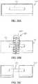
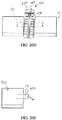
- FIG. 17shows a top view of two pairs of exemplary triple driver assemblies (492) overlapped in the transverse direction and on opposing sides of centerline (430) to represent approximate positions within the plurality of staple pockets (442) as shown in FIG. 18A .
- translating knife member (419)forces wedge sled (456) distally to engage driver cam (494).
- Leading cam surface (460) of cam ramp (458)slides under driver cam (494) and lifts driver cam (494) vertically upwardly along the relatively steep angle of leading cam surface (460). Given the relatively steep angle of leading cam surface (460), the vertical movement is relatively large in view of the relatively small distance that cam ramps (458) slid along through cam slots (457).
- intermediate cam surfaces (462) of cam ramps (458)then slide under driver cams (494) and lift driver cams (494) further vertically upwardly along the relatively gradual angle of intermediate cam surface (460).
- the relatively gradual angle of intermediate cam surface (462)lifts triple driver assemblies (492) a relatively small vertical distance in view of the relatively large distance that cam ramps (458) slide through cam slots (457).
- wedge sled (456)is configured to complete the work to form staple (444) within tissue with less force by taking advantage of the known principle that increasing distance over which a force is applied allows equivalent work to be done with less force.
- translating knife member (419)cuts tissue while simultaneously directing wedge sled (456) to continue to slide distally along centerline (440) such that trailing cam surfaces (464) provide any further upward force necessary to inhibit staples (444) and/or staple drivers (452) from recoiling vertically downwardly.
- trailing cam surface (464)is generally horizontal.
- Wedge sled (456)continues to slide distally toward the distal position along track slot (486) and cam slots (457) to further drive upward movement of triple staple driver assemblies (492) throughout the remaining length of end effector (412).
- FIGS. 20A-20Eshow one example of using end effector (412) to resect tissue, such as a liver parenchyma tissue (310), and to ligate a vessel or duct (316) therein.
- vessel or duct (316)may comprise a hepatic vein or a hepatic artery. It should also be understood that the method may further include the use of end effector (412) to ligate other vessels such as the portal vein and extrahepatic vessels, etc.
- the operatorpositions end effector (412) such that tissue (310), including vessel or duct (316), is located between lower and upper jaws (420, 422).
- tissue (310)including vessel or duct (316)
- the operatorthen compresses tissue (310) between upper and lower crush surfaces (414, 416) of upper and lower jaws (420, 422), respectively, to deliver the predetermined crush pressure to tissue (310).
- jaws (420, 422)may be actuated in this manner by pivoting trigger (24) toward pistol grip (22). It should be understood that jaws (420, 422) need not necessarily be actuated to a fully closed configuration.
- the operatormay rely on tactile feedback through trigger (24) and pistol grip (22) to determine whether the operator has achieved a desired gap between jaws (420,422) to suitably crush tissue (310) without undesirably damaging vessel or duct (316).
- the operatormay rely on visual feedback.
- the crush pressure applied by jaws (420, 422)effectively severs tissue (310), and the operator then removes end effector (412) from tissue (310) to view whether or not any vessels or ducts are present.
- end effector (412)As shown in FIG. 20C , vessel or duct (316) remains intact and is left exposed, extending between severed portions of tissue (310).
- the operatormay leave vessel or duct (316) intact.
- the operatorligates vessel or duct (316) to complete the resection of a severed portion of tissue (310), as shown in FIG. 20D .
- Ligationincludes placement of at least some of overlapping staples (444) within vessel or duct (316) as discussed above in greater detail. It should therefore be understood that the same end effector (412) may be used to crush (and thereby sever) tissue (310) of the liver and also ligate a vessel or duct (316) in the tissue (310).
- the vessel or duct (316)is stapled and severed substantially simultaneously by end effector (412), resulting in the configuration shown in FIG. 20E .
- the severed end (318) of the vessel or duct (316)is sealed by staples (444). Thereby, the operator completes resection of a right portion of tissue (310) and the corresponding portion of the vessel or duct (316).
- the operatorremoves end effector (412) for viewing vessel (316) as shown in FIG. 20C .
- the operatormay apply the predetermined crush pressure (or as determined based on tactile and/or visual feedback as noted above), as shown in FIG. 20B , and immediately thereafter sever and ligate any tissue remaining therein, such as vessel or duct (316).
- the operatormay find such viewing desirable in one or more liver resection procedures.
- tissue resection with end effector (412)may be performed on other tissues within the patient as desired by the user.
- a surgical instrument for treating a tissue of a patientcomprising: (a) a shaft assembly; (b) an end effector extending from the shaft assembly along a jaw centerline, the end effector comprising: (i) a first jaw having an anvil configured to form a plurality of staples pressed against the anvil, and (ii) a second jaw, wherein the first and second jaws are configured to transition between an open configuration and a closed configuration; and (c) a staple cartridge received within the second jaw, the staple cartridge comprising: (i) a deck facing the anvil, wherein the deck defines a plurality of staple openings, the plurality of staple openings comprising a first row of staple openings and a second row of staple openings, the first and second rows of staple openings defining a first row centerline therebetween, (ii) a plurality of staples positioned respectively within the plurality of staple openings, (iii) a first driver assembly positioned on the first row centerline, wherein the first driver is asymmetric about
- the staple cartridgefurther comprises a wedge sled configured to slide proximate to the deck from a proximal sled position to a distal sled position such that the wedge sled is configured to progressively engage the first and second driver assemblies sliding toward the distal sled position and progressively force the first and second portions of the plurality of staples toward the anvil for formation in the tissue.
- Example 2The surgical instrument of Example 2, wherein the wedge sled has a first cam ramp, wherein the first cam ramp is configured to progressively engage the first and second driver assemblies.
- the staple cartridgefurther comprises: (i) a third driver assembly positioned on the second row centerline, wherein the third driver assembly is asymmetric about the second row centerline and is configured to drive a third portion of the plurality of staples, and (ii) a fourth driver assembly positioned on the row centerline and being asymmetric about the second row centerline and configured to drive a fourth portion of the plurality of staples; wherein the wedge sled has a second cam ramp, wherein the second cam ramp is configured to progressively engage the third and fourth driver assemblies.
- the wedge sledhas a distal nose
- the second jawhas a blocker wall distally positioned therein along the centerline, wherein the blocker wall is configured to receive the wedge sled thereagainst and inhibit movement of the wedge sled distally beyond the distal sled position, wherein the blocker wall defines a clearance hole configured to receive the distal nose of the wedge sled in the distal sled position.
- Example 5The surgical instrument of Example 5, wherein the wedge sled has a first cam ramp configured to engage the first and second driver assemblies, wherein the second driver assembly is a distal-most driver assembly, wherein a majority of the first cam ramp in the distal sled position is below the distal-most driver assembly.
- the first driver assemblyhas a first distal driver, a first intermediate driver, and a first proximal driver; wherein the first distal driver, the first intermediate driver, and the first proximal drivers are operatively connected such that the first distal driver and the first proximal driver are longitudinally aligned and the first intermediate driver is transversely offset from each of the first distal driver and the first proximal driver; wherein the first distal driver, the first intermediate driver, and the first proximal driver respectively receive the first portion of the plurality of staples.
- the second driver assemblyhas a second distal driver, a second intermediate driver, and a second proximal driver; wherein the second distal driver, the second intermediate driver, and the second proximal drivers are operatively connected such that the second distal driver and the second proximal driver are longitudinally aligned and the second intermediate driver is transversely offset from each of the second distal driver and the second proximal driver; wherein the second distal driver, the second intermediate driver, and the second proximal driver respectively receive the second portion of the plurality of staples.
- Example 10The surgical instrument of Example 10, wherein the first and second driver assemblies alternate such that first and second intermediate drivers of the respective first and second driver assemblies are positioned on opposing sides of the first row centerline.
- Example 11The surgical instrument of Example 11, wherein the first distal driver of the first driver assembly overlaps in the direction transverse to the first row centerline with the second proximal driver of the second driver assembly.
- the staple cartridgefurther comprises a wedge sled configured to slide proximate to the deck from a proximal sled position to a distal sled position such that the wedge sled is configured to engage the first driver cam thereby forcing the first distal driver, the first intermediate driver, and the first proximal driver toward the anvil for forming the first portion of the plurality of staples against the anvil.
- 2012/0199630entitled “Robotically-Controlled Surgical Instrument with Force-Feedback Capabilities,” published August 9, 2012; U.S. Pub. No. 2012/0132450 , entitled “Shiftable Drive Interface for Robotically-Controlled Surgical Tool,” published May 31,2012; U.S. Pub. No. 2012/0199633 , entitled “Surgical Stapling Instruments with Cam-Driven Staple Deployment Arrangements,” published August 9, 2012; U.S. Pub. No. 2012/0199631 , entitled “Robotically-Controlled Motorized Surgical End Effector System with Rotary Actuated Closure Systems Having Variable Actuation Speeds,” published August 9, 2012; U.S. Pub. No.
- 2012/0199632entitled “Robotically-Controlled Surgical Instrument with Selectively Articulatable End Effector,” published August 9, 2012; U.S. Pub. No. 2012/0203247 , entitled “Robotically-Controlled Surgical End Effector System,” published August 9, 2012; U.S. Pub. No. 2012/0211546 , entitled “Drive Interface for Operably Coupling a Manipulatable Surgical Tool to a Robot,” published August 23, 2012; U.S. Pub. No. 2012/0138660 , entitled “Robotically-Controlled Cable-Based Surgical End Effectors,” published June 7, 2012; and/or U.S. Pub. No. 2012/0205421 , entitled “Robotically-Controlled Surgical End Effector System with Rotary Actuated Closure Systems,” published August 16, 2012.
- Versions of the devices described abovemay be designed to be disposed of after a single use, or they can be designed to be used multiple times. Versions may, in either or both cases, be reconditioned for reuse after at least one use. Reconditioning may include any combination of the steps of disassembly of the device, followed by cleaning or replacement of particular pieces, and subsequent reassembly. In particular, some versions of the device may be disassembled, and any number of the particular pieces or parts of the device may be selectively replaced or removed in any combination. Upon cleaning and/or replacement of particular parts, some versions of the device may be reassembled for subsequent use either at a reconditioning facility, or by a operator immediately prior to a procedure.
- reconditioning of a devicemay utilize a variety of techniques for disassembly, cleaning/replacement, and reassembly. Use of such techniques, and the resulting reconditioned device, are all within the scope of the present application.
- versions described hereinmay be sterilized before and/or after a procedure.
- the deviceis placed in a closed and sealed container, such as a plastic or TYVEK bag.
- the container and devicemay then be placed in a field of radiation that can penetrate the container, such as gamma radiation, x-rays, or high-energy electrons.
- the radiationmay kill bacteria on the device and in the container.
- the sterilized devicemay then be stored in the sterile container for later use.
- a devicemay also be sterilized using any other technique known in the art, including but not limited to beta or gamma radiation, ethylene oxide, or steam.
Landscapes
- Health & Medical Sciences (AREA)
- Life Sciences & Earth Sciences (AREA)
- Surgery (AREA)
- Heart & Thoracic Surgery (AREA)
- Engineering & Computer Science (AREA)
- Biomedical Technology (AREA)
- Nuclear Medicine, Radiotherapy & Molecular Imaging (AREA)
- Medical Informatics (AREA)
- Molecular Biology (AREA)
- Animal Behavior & Ethology (AREA)
- General Health & Medical Sciences (AREA)
- Public Health (AREA)
- Veterinary Medicine (AREA)
- Surgical Instruments (AREA)
Abstract
Description
- In some settings, endoscopic surgical instruments may be preferred over traditional open surgical devices since a smaller incision may reduce the post-operative recovery time and complications. Consequently, some endoscopic surgical instruments may be suitable for placement of a distal end effector at a desired surgical site through the cannula of a trocar. These distal end effectors may engage tissue in a number of ways to achieve a diagnostic or therapeutic effect (e.g., endocutter, grasper, cutter, stapler, clip applier, access device, drug/gene therapy delivery device, and energy delivery device using ultrasonic vibration, RF, laser, etc.). Endoscopic surgical instruments may include a shaft between the end effector and a handle portion, which is manipulated by the clinician. Such a shaft may enable insertion to a desired depth and rotation about the longitudinal axis of the shaft, thereby facilitating positioning of the end effector within the patient. Positioning of an end effector may be further facilitated through inclusion of one or more articulation joints or features, enabling the end effector to be selectively articulated or otherwise deflected relative to the longitudinal axis of the shaft.
- Examples of endoscopic surgical instruments include surgical staplers. Some such staplers are operable to clamp down on layers of tissue, cut through the clamped layers of tissue, and drive staples through the layers of tissue to substantially seal the severed layers of tissue together near the severed ends of the tissue layers. Merely exemplary surgical staplers are disclosed in
U.S. Pat. No. 4,805,823 , entitled "Pocket Configuration for Internal Organ Staplers," issued February 21, 1989;U.S. Pat. No. 5,415,334 , entitled "Surgical Stapler and Staple Cartridge," issued May 16, 1995;U.S. Pat. No. 5,465,895 , entitled "Surgical Stapler Instrument," issued November 14, 1995;U.S. Pat. No. 5,597,107 , entitled "Surgical Stapler Instrument," issued January 28, 1997;U.S. Pat. No. 5,632,432 , entitled "Surgical Instrument," issued May 27, 1997;U.S. Pat. No. 5,673,840 , entitled "Surgical Instrument," issued October 7, 1997;U.S. Pat. No. 5,704,534 , entitled "Articulation Assembly for Surgical Instruments," issued January 6, 1998;U.S. Pat. No. 5,814,055 , entitled "Surgical Clamping Mechanism," issued September 29,1998;U.S. Pat. No. 6,978,921 , entitled "Surgical Stapling Instrument Incorporating an E-Beam Firing Mechanism," issued December 27, 2005;U.S. Pat. No. 7,000,818 , entitled "Surgical Stapling Instrument Having Separate Distinct Closing and Firing Systems," issued February 21,2006;U.S. Pat. No. 7,143,923 , entitled "Surgical Stapling Instrument Having a Firing Lockout for an Unclosed Anvil," issued December 5, 2006;U.S. Pat. No. 7,303,108 , entitled "Surgical Stapling Instrument Incorporating a Multi-Stroke Firing Mechanism with a Flexible Rack," issued December 4, 2007;U.S. Pat. No. 7,367,485 , entitled "Surgical Stapling Instrument Incorporating a Multistroke Firing Mechanism Having a Rotary Transmission," issued May 6, 2008;U.S. Pat. No. 7,380,695 , entitled "Surgical Stapling Instrument Having a Single Lockout Mechanism for Prevention of Firing," issued June 3, 2008;U.S. Pat. No. 7,380,696 , entitled "Articulating Surgical Stapling Instrument Incorporating a Two-Piece E-Beam Firing Mechanism," issued June 3, 2008;U.S. Pat. No. 7,404,508 , entitled "Surgical Stapling and Cutting Device," issued July 29, 2008;U.S. Pat. No. 7,434,715 , entitled "Surgical Stapling Instrument Having Multistroke Firing with Opening Lockout," issued October 14, 2008;U.S. Pat. No. 7,721,930 , entitled "Disposable Cartridge with Adhesive for Use with a Stapling Device," issued May 25, 2010;U.S. Pat. No. 8,408,439 , entitled "Surgical Stapling Instrument with An Articulatable End Effector," issued April 2, 2013; andU.S. Pat. No. 8,453,914 , entitled "Motor-Driven Surgical Cutting Instrument with Electric Actuator Directional Control Assembly," issued June 4, 2013. - While the surgical staplers referred to above are described as being used in endoscopic procedures, it should be understood that such surgical staplers may also be used in open procedures and/or other non-endoscopic procedures. By way of example only, a surgical stapler may be inserted through a thoracotomy, and thereby between a patient's ribs, to reach one or more organs in a thoracic surgical procedure that does not use a trocar as a conduit for the stapler. Such procedures may include the use of the stapler to sever and close a vessel leading to a lung. For instance, the vessels leading to an organ may be severed and closed by a stapler before removal of the organ from the thoracic cavity. Of course, surgical staplers may be used in various other settings and procedures.
- Examples of surgical staplers that may be particularly suited or use through a thoracotomy are disclosed in
U.S. Patent App. No. 14/810,786 U.S. Patent Pub. No. 2014/0243801 U.S. Patent Pub. No. 2014/0239041 U.S. Patent Pub. No. 2014/0239042 , entitled "Integrated Tissue Positioning and Jaw Alignment Features for Surgical Stapler," published August 28, 2014;U.S. Patent Pub. No. 2014/0239036 U.S. Patent Pub. No. 2014/0239040 U.S. Patent Pub. No. 2014/0239043 , entitled "Distal Tip Features for End Effector of Surgical Instrument," published August 28, 2014;U.S. Patent Pub. No. 2014/0239037 , entitled "Staple Forming Features for Surgical Stapling Instrument," published August 28, 2014;U.S. Patent Pub. No. 2014/0239038 , entitled "Surgical Instrument with Multi-Diameter Shaft," published August 28, 2014; andU.S. Patent Pub. No. 2014/0239044 , entitled "Installation Features for Surgical Instrument End Effector Cartridge," published August 28, 2014. - While various kinds of surgical stapling instruments and associated components have been made and used, it is believed that no one prior to the inventor(s) has made or used the invention described in the appended claims.
- The accompanying drawings, which are incorporated in and constitute a part of this specification, illustrate embodiments of the invention, and, together with the general description of the invention given above, and the detailed description of the embodiments given below, serve to explain the principles of the present invention.
FIG. 1 depicts a perspective view of an exemplary articulating surgical stapling instrument;FIG. 2 depicts a side elevational view of the instrument ofFIG. 1 ;FIG. 3 depicts a perspective view of an end effector of the instrument ofFIG. 1 , with the end effector in a closed configuration;FIG. 4 depicts a perspective view of the end effector ofFIG. 3 , with the end effector in an open configuration;FIG. 5 depicts an exploded perspective view of the end effector ofFIG. 3 ;FIG. 6 depicts a cross-sectional end view of the end effector ofFIG. 3 , taken along line 6-6 ofFIG. 4 ;FIG. 7A depicts a cross-sectional side view of the end effector ofFIG. 3 , taken along line 7-7 ofFIG. 4 , with a firing beam in a proximal position;FIG. 7B depicts a cross-sectional side view of the end effector ofFIG. 3 , taken along line 7-7 ofFIG. 4 , with the firing beam in a distal position;FIG. 8 depicts a perspective view of the end effector ofFIG. 3 , positioned at tissue and having been actuated once in the tissue;FIG. 9 depicts a side elevational view of another exemplary articulating surgical stapling instrument;FIG. 10 depicts a perspective view of an end effector of the instrument ofFIG. 9 , with the end effector in an open configuration;FIG. 11 depicts a top view of a lower jaw of the end effector ofFIG. 10 ;FIG. 12 depicts a bottom view of an upper jaw of the end effector ofFIG. 10 ;FIG. 13 depicts an exploded perspective view of the lower jaw ofFIG. 10 ;FIG. 14 depicts a perspective view of a wedge sled of the lower jaw shown inFIG. 13 ;FIG. 15 depicts a right perspective view of a triple driver assembly of the lower jaw ofFIG. 10 ;FIG. 16 depicts a right perspective view of another triple driver assembly of the lower jaw ofFIG. 10 ;FIG. 17 depicts atop view of an arrangement of triple driver assemblies of the lower jaw ofFIG. 10 ;FIG. 18A depicts a side cross-sectional view of the wedge sled ofFIG. 14 at a first longitudinal position, sliding toward the triple driver assemblies ofFIG. 17 , taken generally along a centerline of the lower jaw ofFIG. 13 ;FIG. 18B depicts a side cross-sectional view of the wedge sled ofFIG. 14 at a second longitudinal position, with the triple driver assemblies ofFIG. 17 in an upper position, taken generally along a centerline of the lower jaw ofFIG. 13 ;FIG. 19 depicts a perspective view of the lower jaw ofFIG. 13 , in partial cross-section taken along section line 19-19 ofFIG. 11 ;FIG. 20A depicts a schematic representation of a liver having a vessel extending through the liver tissue;FIG. 20B depicts the schematic representation of the end effector ofFIG. 10 severing the liver tissue ofFIG. 20A ;FIG. 20C depicts the schematic representation of the vessel ofFIG. 20B exposed from the severed liver tissue ofFIG. 20A ;FIG. 20D depicts the schematic representation of the end effector ofFIG. 10 stapling the exposed vessel ofFIG. 20C ; andFIG. 20E depicts the schematic representation of the liver tissue ofFIG. 20A having a portion of the liver tissue and the vessel resected therefrom.- The drawings are not intended to be limiting in any way, and it is contemplated that various embodiments of the invention may be carried out in a variety of other ways, including those not necessarily depicted in the drawings. The accompanying drawings incorporated in and forming a part of the specification illustrate several aspects of the present invention, and together with the description serve to explain the principles of the invention; it being understood, however, that this invention is not limited to the precise arrangements shown.
- The following description of certain examples of the invention should not be used to limit the scope of the present invention. Other examples, features, aspects, embodiments, and advantages of the invention will become apparent to those skilled in the art from the following description, which is by way of illustration, one of the best modes contemplated for carrying out the invention. As will be realized, the invention is capable of other different and obvious aspects, all without departing from the invention. Accordingly, the drawings and descriptions should be regarded as illustrative in nature and not restrictive.
FIG. 1 depicts an exemplary surgical stapling and severing instrument (10) that includes a handle assembly (20), a shaft assembly (30), and an end effector (40). End effector (40) and the distal portion of shaft assembly (30) are sized for insertion, in a nonarticulated state as depicted inFIG. 1 , through a trocar cannula to a surgical site in a patient for performing a surgical procedure. By way of example only, such a trocar may be inserted in a patient's abdomen, between two of the patient's ribs, or elsewhere. In some settings, instrument (10) is used without a trocar. For instance, end effector (40) and the distal portion of shaft assembly (30) may be inserted directly through a thoracotomy or other type of incision. It should be understood that terms such as "proximal" and "distal" are used herein with reference to a clinician gripping handle assembly (20) of instrument (10). Thus, end effector (40) is distal with respect to the more proximal handle assembly (20). It will be further appreciated that for convenience and clarity, spatial terms such as "vertical" and "horizontal" are used herein with respect to the drawings. However, surgical instruments are used in many orientations and positions, and these terms are not intended to be limiting and absolute.- As shown in
FIGS. 1-2 , handle assembly (20) of the present example comprises pistol grip (22), a closure trigger (24), and a firing trigger (26). Each trigger (24, 26) is selectively pivotable toward and away from pistol grip (22) as will be described in greater detail below. Handle assembly (20) further includes an anvil release button (25), a firing beam reverse switch (27), and a removable battery pack (28). These components will also be described in greater detail below. Of course, handle assembly (20) may have a variety of other components, features, and operabilities, in addition to or in lieu of any of those noted above. Other suitable configurations for handle assembly (20) will be apparent to those of ordinary skill in the art in view of the teachings herein. - As shown in
FIGS. 1-3 , shaft assembly (30) of the present example comprises an outer closure tube (32), an articulation section (34), and a closure ring (36), which is further coupled with end effector (40). Closure tube (32) extends along the length of shaft assembly (30). Closure ring (36) is positioned distal to articulation section (34). Closure tube (32) and closure ring (36) are configured to translate longitudinally relative to handle assembly (20). Longitudinal translation of closure tube (32) is communicated to closure ring (36) via articulation section (34). Exemplary features that may be used to provide longitudinal translation of closure tube (32) and closure ring (36) will be described in greater detail below. - Articulation section (34) is operable to laterally deflect closure ring (36) and end effector (40) laterally away from the longitudinal axis (LA) of shaft assembly (30) at a desired angle (α). End effector (40) may thereby reach behind an organ or approach tissue from a desired angle or for other reasons. In some versions, articulation section (34) enables deflection of end effector (40) along a single plane. In some other versions, articulation section (34) enables deflection of end effector along more than one plane. In the present example, articulation is controlled through an articulation control knob (35) which is located at the proximal end of shaft assembly (30). Knob (35) is rotatable about an axis that is perpendicular to the longitudinal axis (LA) of shaft assembly (30). Closure ring (36) and end effector (40) pivot about an axis that is perpendicular to the longitudinal axis (LA) of shaft assembly (30) in response to rotation of knob (35). By way of example only, rotation of knob (35) clockwise may cause corresponding clockwise pivoting of closure ring (36) and end effector (40) at articulation section (34). Articulation section (34) is configured to communicate longitudinal translation of closure tube (32) to closure ring (36), regardless of whether articulation section (34) is in a straight configuration or an articulated configuration.
- In some versions, articulation section (34) and/or articulation control knob (35) are/is constructed and operable in accordance with at least some of the teachings of
U.S. Pub. No. 2014/0243801 , entitled "Surgical Instrument End Effector Articulation Drive with Pinion and Opposing Racks," published August 28, 2014. Articulation section (34) may also be constructed and operable in accordance with at least some of the teachings ofU.S. Pat. App. No. 14/314,125 - As shown in
FIGS. 1-2 , shaft assembly (30) of the present example further includes a rotation knob (31). Rotation knob (31) is operable to rotate the entire shaft assembly (30) and end effector (40) relative to handle assembly (20) about the longitudinal axis (LA) of shaft assembly (30). In some versions, rotation knob (31) is operable to selectively lock the angular position of shaft assembly (30) and end effector (40) relative to handle assembly (20) about the longitudinal axis (LA) of shaft assembly (30). For instance, rotation knob (31) may be translatable between a first longitudinal position, in which shaft assembly (30) and end effector (40) are rotatable relative to handle assembly (20) about the longitudinal axis (LA) of shaft assembly (30); and a second longitudinal position, in which shaft assembly (30) and end effector (40) are not rotatable relative to handle assembly (20) about the longitudinal axis (LA) of shaft assembly (30). Of course, shaft assembly (30) may have a variety of other components, features, and operabilities, in addition to or in lieu of any of those noted above. By way of example only, at least part of shaft assembly (30) is constructed in accordance with at least some of the teachings ofU.S. Pub. No. 2014/0239038 , entitled "Surgical Instrument with Multi-Diameter Shaft," published August 28, 2014. Other suitable configurations for shaft assembly (30) will be apparent to those of ordinary skill in the art in view of the teachings herein. - As also shown in
FIGS. 3-5 , end effector (40) of the present example includes a lower jaw (50) and a pivotable anvil (60). Anvil (60) includes a pair of integral, outwardly extending pins (66) that are disposed in corresponding curved slots (54) of lower jaw (50). Anvil (60) is pivotable toward and away from lower jaw (50) between an open position (shown inFIGS. 2 and4 ) and a closed position (shown inFIGS. 1 ,3 , and7A-7B ). Use of the term "pivotable" (and similar terms with "pivot" as a base) should not be read as necessarily requiring pivotal movement about a fixed axis. For instance, in the present example, anvil (60) pivots about an axis that is defined by pins (66), which slide along curved slots (54) of lower jaw (50) as anvil (60) moves toward lower jaw (50). In such versions, the pivot axis translates along the path defined by slots (54) while anvil (60) simultaneously pivots about that axis. In addition or in the alternative, the pivot axis may slide along slots (54) first, with anvil (60) then pivoting about the pivot axis after the pivot axis has slid a certain distance along the slots (54). It should be understood that such sliding/translating pivotal movement is encompassed within terms such as "pivot," "pivots," "pivotal," "pivotable," "pivoting," and the like. Of course, some versions may provide pivotal movement of anvil (60) about an axis that remains fixed and does not translate within a slot or channel, etc. - As best seen in
FIG. 5 , lower jaw (50) of the present example defines a channel (52) that is configured to receive a staple cartridge (70). Staple cartridge (70) may be inserted into channel (52), end effector (40) may be actuated, and then staple cartridge (70) may be removed and replaced with another staple cartridge (70). Lower jaw (50) thus releasably retains staple cartridge (70) in alignment with anvil (60) for actuation of end effector (40). In some versions, lower jaw (50) is constructed in accordance with at least some of the teachings ofU.S. Pub. No. 2014/0239044 , entitled "Installation Features for Surgical Instrument End Effector Cartridge," published August 28, 2014. Other suitable forms that lower jaw (50) may take will be apparent to those of ordinary skill in the art in view of the teachings herein. - As best seen in
FIGS. 4-6 , staple cartridge (70) of the present example comprises a cartridge body (71) and a tray (76) secured to the underside of cartridge body (71). The upper side of cartridge body (71) presents a deck (73), against which tissue may be compressed when anvil (60) is in a closed position. Cartridge body (71) further defines a longitudinally extending channel (72) and a plurality of staple pockets (74). A staple (77) is positioned in each staple pocket (74). A staple driver (75) is also positioned in each staple pocket (74), underneath a corresponding staple (77), and above tray (76). As will be described in greater detail below, staple drivers (75) are operable to translate upwardly in staple pockets (74) to thereby drive staples (77) upwardly through staple pockets (74) and into engagement with anvil (60). Staple drivers (75) are driven upwardly by a wedge sled (78), which is captured between cartridge body (71) and tray (76), and which translates longitudinally through cartridge body (71). Wedge sled (78) includes a pair of obliquely angled cam surfaces (79), which are configured to engage staple drivers (75) and thereby drive staple drivers (75) upwardly as wedge sled (78) translates longitudinally through cartridge (70). For instance, when wedge sled (78) is in a proximal position as shown inFIG. 7A , staple drivers (75) are in downward positions and staples (77) are located in staple pockets (74). As wedge sled (78) is driven to the distal position shown inFIG. 7B by a translating knife member (80), wedge sled (78) drives staple drivers (75) upwardly, thereby driving staples (77) out of staple pockets (74) and into staple forming pockets (64). Thus, staple drivers (75) translate along a vertical dimension as wedge sled (78) translates along a horizontal dimension. - It should be understood that the configuration of staple cartridge (70) may be varied in numerous ways. For instance, staple cartridge (70) of the present example includes two longitudinally extending rows of staple pockets (74) on one side of channel (72); and another set of two longitudinally extending rows of staple pockets (74) on the other side of channel (72). However, in some other versions, staple cartridge (70) includes three, one, or some other number of staple pockets (74) on each side of channel (72). In some versions, staple cartridge (70) is constructed and operable in accordance with at least some of the teachings of
U.S. Pub. No. 2014/0239042 , entitled "Integrated Tissue Positioning and Jaw Alignment Features for Surgical Stapler," published August 28, 2014. In addition or in the alternative, staple cartridge (70) may be constructed and operable in accordance with at least some of the teachings ofU.S. Pub. No. 2014/0239044 , entitled "Installation Features for Surgical Instrument End Effector Cartridge," published August 28, 2014. Other suitable forms that staple cartridge (70) may take will be apparent to those of ordinary skill in the art in view of the teachings herein. - As best seen in
FIG. 4 , anvil (60) of the present example comprises a longitudinally extending channel (62) and a plurality of staple forming pockets (64). Channel (62) is configured to align with channel (72) of staple cartridge (70) when anvil (60) is in a closed position. Each staple forming pocket (64) is positioned to lie over a corresponding staple pocket (74) of staple cartridge (70) when anvil (60) is in a closed position. Staple forming pockets (64) are configured to deform the legs of staples (77) when staples (77) are driven through tissue and into anvil (60). In particular, staple forming pockets (64) are configured to bend the legs of staples (77) to secure the formed staples (77) in the tissue. Anvil (60) may be constructed in accordance with at least some of the teachings ofU.S. Pub. No. 2014/0239042 , entitled "Integrated Tissue Positioning and Jaw Alignment Features for Surgical Stapler," published August 28, 2014; at least some of the teachings ofU.S. Pub. No. 2014/0239036 , entitled "Jaw Closure Feature for End Effector of Surgical Instrument," published August 28, 2014; and/or at least some of the teachings ofU.S. Pub. No. 2014/0239037 , entitled "Staple Forming Features for Surgical Stapling Instrument," published August 28, 2014. Other suitable forms that anvil (60) may take will be apparent to those of ordinary skill in the art in view of the teachings herein. - In the present example, knife member (80) is configured to translate through end effector (40). As best seen in
FIGS. 5 and7A-7B , knife member (80) is secured to the distal end of a firing beam (82), which extends through a portion of shaft assembly (30). As best seen inFIGS. 4 and6 , knife member (80) is positioned in channels (62, 72) of anvil (60) and staple cartridge (70). Knife member (80) includes a distally presented cutting edge (84) that is configured to sever tissue that is compressed between anvil (60) and deck (73) of staple cartridge (70) as knife member (80) translates distally through end effector (40). As noted above and as shown inFIGS. 7A-7B , knife member (80) also drives wedge sled (78) distally as knife member (80) translates distally through end effector (40), thereby driving staples (77) through tissue and against anvil (60) into formation. Various features that may be used to drive knife member (80) distally through end effector (40) will be described in greater detail below. - In some versions, end effector (40) includes lockout features that are configured to prevent knife member (80) from advancing distally through end effector (40) when a staple cartridge (70) is not inserted in lower jaw (50). In addition or in the alternative, end effector (40) may include lockout features that are configured to prevent knife member (80) from advancing distally through end effector (40) when a staple cartridge (70) that has already been actuated once (e.g., with all staples (77) deployed therefrom) is inserted in lower jaw (50). By way of example only, such lockout features may be configured in accordance with at least some of the teachings of
U.S. Pub. No. 2014/0239041 , entitled "Lockout Feature for Movable Cutting Member of Surgical Instrument," published August 28, 2014; and/or at least some of the teachings ofU.S. Pat. App. No. 14/314,108 - In the present example, anvil (60) is driven toward lower jaw (50) by advancing closure ring (36) distally relative to end effector (40). Closure ring (36) cooperates with anvil (60) through a camming action to drive anvil (60) toward lower jaw (50) in response to distal translation of closure ring (36) relative to end effector (40). Similarly, closure ring (36) may cooperate with anvil (60) to open anvil (60) away from lower jaw (50) in response to proximal translation of closure ring (36) relative to end effector (40). By way of example only, closure ring (36) and anvil (60) may interact in accordance with at least some of the teachings of
U.S. Pub. No. 2014/0239036 , entitled "Jaw Closure Feature for End Effector of Surgical Instrument," published August 28, 2014; and/or in accordance with at least some of the teachings ofU.S. Patent App. No. 14/314,108 - As noted above, handle assembly (20) includes pistol grip (22) and closure trigger (24). As also noted above, anvil (60) is closed toward lower jaw (50) in response to distal advancement of closure ring (36). In the present example, closure trigger (24) is pivotable toward pistol grip (22) to drive closure tube (32) and closure ring (36) distally. Various suitable components that may be used to convert pivotal movement of closure trigger (24) toward pistol grip (22) into distal translation of closure tube (32) and closure ring (36) relative to handle assembly (20) will be apparent to those of ordinary skill in the art in view of the teachings herein. When closure trigger (24) reaches a fully pivoted state, such that anvil (60) is in a fully closed position relative to lower jaw (50), locking features in handle assembly (20) lock the position of closure trigger (24) and closure tube (32), thereby locking anvil (60) in a fully closed position relative to lower jaw (50). These locking features are released by actuation of anvil release button (25). Anvil release button (25) is configured and positioned to be actuated by the thumb of the operator hand that grasps pistol grip (22). In other words, the operator may grasp pistol grip (22) with one hand, actuate closure trigger (24) with one or more fingers of the same hand, and then actuate anvil release button (25) with the thumb of the same hand, without ever needing to release the grasp of pistol grip (22) with the same hand. Other suitable features that may be used to actuate anvil (60) will be apparent to those of ordinary skill in the art in view of the teachings herein.
- In the present example, instrument (10) provides motorized control of firing beam (82). In particular, instrument (10) includes motorized components that are configured to drive firing beam (82) distally in response to pivoting of firing trigger (26) toward pistol grip (22). In some versions, a motor (not shown) is contained in pistol grip (22) and receives power from battery pack (28). This motor is coupled with a transmission assembly (not shown) that converts rotary motion of a drive shaft of the motor into linear translation of firing beam (82). In some such versions, firing beam (82) may only be advanced distally when anvil (60) is in a fully closed position relative to lower jaw (50). After firing beam (82) is advanced distally to sever tissue and drive staples (77) as described above with reference to
FIGS. 7A-7B , the drive assembly for firing beam (82) may be automatically reversed to drive firing beam (82) proximally back to the retracted position (e.g., back from the position shown inFIG. 7B to the position shown inFIG. 7A ). Alternatively, the operator may actuate firing beam reverse switch (27), which may reverse the drive assembly for firing beam (82) in order to retract firing beam (82) to a proximal position. Handle assembly (20) of the present example further includes a bailout feature (21), which is operable to provide a mechanical bailout allowing the operator to manually retract firing beam (82) proximally (e.g., in the event of power loss while firing beam (82) is in a distal position, etc.). - By way of example only, the features that are operable to provide motorized actuation of firing beam (82) may be configured and operable in accordance with at least some of the teachings of
U.S. Pat. No. 8,210,411 , entitled "Motor-Driven Surgical Instrument," issued July 3, 2012. As another merely illustrative example, the features that are operable to provide motorized actuation of firing beam (82) may be configured and operable in accordance with at least some of the teachings ofU.S. Pat. No. 8,453,914 , entitled "Motor-Driven Surgical Cutting Instrument with Electric Actuator Directional Control Assembly," issued June 4, 2013. As yet another merely illustrative example, the features that are operable to provide motorized actuation of firing beam (82) may be configured and operable in accordance with at least some of the teachings ofU.S. Patent App. No. 14/226,142 - Other suitable components, features, and configurations that may be used to provide motorization of firing beam (82) will be apparent to those of ordinary skill in the art in view of the teachings herein. It should also be understood that some other versions may provide manual driving of firing beam (82), such that a motor may be omitted. By way of example only, firing beam (82) may be manually actuated in accordance with at least some of the teachings of any other reference cited herein.
FIG. 8 shows end effector (40) having been actuated through a single stroke through tissue (90). As shown, cutting edge (84) (obscured inFIG. 8 ) has cut through tissue (90), while staple drivers (75) have driven two alternating rows of staples (77) through the tissue (90) on each side of the cut line produced by cutting edge (84). Staples (77) are all oriented substantially parallel to the cut line in this example, though it should be understood that staples (77) may be positioned at any suitable orientations. In the present example, end effector (40) is withdrawn from the trocar after the first stroke is complete, the spent staple cartridge (70) is replaced with a new staple cartridge (70), and end effector (40) is then again inserted through the trocar to reach the stapling site for further cutting and stapling. This process may be repeated until the desired amount of cuts and staples (77) have been provided. Anvil (60) may need to be closed to facilitate insertion and withdrawal through the trocar; and anvil (60) may need to be opened to facilitate replacement of staple cartridge (70).- It should be understood that cutting edge (84) may cut tissue substantially contemporaneously with staples (77) being driven through tissue during each actuation stroke. In the present example, cutting edge (84) just slightly lags behind driving of staples (77), such that staple (77) is driven through the tissue just before cutting edge (84) passes through the same region of tissue, though it should be understood that this order may be reversed or that cutting edge (84) may be directly synchronized with adjacent staples. While
FIG. 8 shows end effector (40) being actuated in two layers (92, 94) of tissue (90), it should be understood that end effector (40) may be actuated through a single layer of tissue (90) or more than two layers (92, 94) of tissue. It should also be understood that the formation and positioning of staples (77) adjacent to the cut line produced by cutting edge (84) may substantially seal the tissue at the cut line, thereby reducing or preventing bleeding and/or leaking of other bodily fluids at the cut line. Furthermore, whileFIG. 8 shows end effector (40) being actuated in two substantially flat, apposed planar layers (92, 94) of tissue, it should be understood that end effector (40) may also be actuated across a tubular structure such as a blood vessel, a section of the gastrointestinal tract, etc.FIG. 8 should therefore not be viewed as demonstrating any limitation on the contemplated uses for end effector (40). Various suitable settings and procedures in which instrument (10) may be used will be apparent to those of ordinary skill in the art in view of the teachings herein. - It should also be understood that any other components or features of instrument (10) may be configured and operable in accordance with any of the various references cited herein. Additional exemplary modifications that may be provided for instrument (10) will be described in greater detail below. Various suitable ways in which the below teachings may be incorporated into instrument (10) will be apparent to those of ordinary skill in the art. Similarly, various suitable ways in which the below teachings may be combined with various teachings of the references cited herein will be apparent to those of ordinary skill in the art. It should also be understood that the below teachings are not limited to instrument (10) or devices taught in the references cited herein. The below teachings may be readily applied to various other kinds of instruments, including instruments that would not be classified as surgical staplers. Various other suitable devices and settings in which the below teachings may be applied will be apparent to those of ordinary skill in the art in view of the teachings herein.
- While the above surgical instrument (10) provides one example of an end effector (40) that may be used to staple and sever tissue within a patient, it will be appreciated that the human body is comprised a wide variety of tissues located in distinct, sometimes difficult to access regions throughout the patient. For example, a liver includes tissue including vessels or ducts passing throughout. In settings where the liver includes a tumor, it may be desirable to resect the portion of the liver containing the tumor. The resection may be anatomic (e.g., resection of the right or left side of the liver, inclusive of the lobes on that side) or non-anatomic (e.g., resection of just a single lobe or wedge of liver tissue). This resection process may entail at least three kinds of steps - a first step to dissect the tissue (e.g., liver parenchyma) around the vessels or ducts, to thereby isolate or reveal the vessels or ducts; a second step to ligate those vessels or ducts; and a third step to sever the ligated vessels or ducts.
- One such method of liver resection includes the well known Kelly clamp method, where a Kelly style clamp is used to compress the liver tissue and thereby dissect the tissue through a crushing action. However, treatments may require many instruments to accommodate such a wide variety of tissues and vessels or ducts within the human body, thereby adding to the time and complexity associated with assessing the state of the tissue, selecting and/or changing instruments, and performing the resection. It may therefore be desirable to provide a surgical instrument (410) with an end effector (412) having a pair of crush surfaces (414, 416) that are configured to sever tissue by crushing the tissue; while also providing an adjacent staple cartridge (418) to selectively ligate one or more vessels or ducts passing through the tissue. Thereby, a single surgical instrument (210, 410) will allow the operator to more quickly assess the tissue and proceed with further tissue dissection and/or ligation of vessels and ducts.
- Surgical instruments (410) are described below in the context of dissecting liver tissue (e.g., liver parenchyma) with crush surfaces (414, 416) and using staples to ligate associated vessels or ducts (e.g., portal vein, hepatic vein branches, hepatic artery branches, extrahepatic vessels, etc.). In some instances (e.g., in the case of hepatic vein branches and hepatic artery branches, etc.), the vessel or duct that is sealed by the staples is exposed when the operator crushes the liver tissue with surfaces (414, 416). In some other instances (e.g., in the case of the portal vein and extrahepatic vessels, etc.), the vessel or duct that is sealed by the staples is separate from the liver tissue that the operator has crushed with surfaces (414, 416). While the following description of surgical instruments (410) and method of treatment is provided in the context of liver resection, it will be appreciated that surgical instruments (410) may be alternatively configured to treat any tissue in the human body with similar features. It should also be understood that that the features discussed below may be readily incorporated into surgical instrument (10) discussed above. To this end, like numbers indicate like features described above in greater detail.
- In the following examples, end effectors (412) apply at least two laterally spaced apart rows of staples where the staples in one row have the same height as the staples in another row. In some variations, end effectors (412) are modified to apply at least two laterally spaced apart rows of staples where the staples in one row have a height that is different from the height of the staples in another row.
FIGS. 9-13 show surgical instrument (410) with end effector (412) having upper crush surface (414), lower crush surface (416), staple cartridge (418), and knife member (419). As noted above, it may be desirable to provide such a surgical instrument (410) with an end effector (412) having crush surfaces (414, 416) that are configured to sever tissue by crushing the tissue; while also providing adjacent staple cartridge (418) to selectively ligate one or more vessels passing through the tissue. In addition, knife member (419) is configured to cut the one or more vessels for complete removal of the surrounding tissue. Thereby, surgical instrument (410) will allow the operator to more quickly assess the tissue and proceed with further tissue severing and/or tissue ligation. Surgical instrument (410) of the present example also includes handle assembly (20) and shaft assembly (30) discussed above in greater detail. Except as otherwise described below, end effector (412), in conjunction with handle assembly (20) and shaft assembly (30), is configured and operable similar to end effector (40)(seeFIG. 1 ). By way of example only, end effector (412) may have a length of approximately 40 mm and a width of approximately 7mm. Alternatively, any other suitable dimension may be used.- End effector (412) of the present example includes a lower jaw (420) and an upper jaw (422), which forms an anvil (424). Upper jaw (422) is pivotally mounted relative to lower jaw (420) for receiving the tissue therebetween. More particularly, anvil (424) is pivotable toward and away from lower jaw (420) between an open position and a closed position (e.g., in response to pivotal movement of trigger (24) toward and away from pistol grip (22)). For instance, in the present example, anvil (424) pivots about an axis that is defined by pins (not shown), which slide along curved slots (not shown) of lower jaw (420) as anvil (424) moves toward lower jaw (420). In such versions, the pivot axis translates along the path defined by slots (not shown) while anvil (424) simultaneously pivots about that axis. In addition or in the alternative, the pivot axis may slide along slots (not shown) first, with anvil (424) then pivoting about the pivot axis after the pivot axis slides a certain distance along the slots (not shown). Alternatively, some versions may provide pivotal movement of anvil (424) about an axis that remains fixed and does not translate within a slot or channel, etc.
- As best seen in
FIGS. 11-13 , lower jaw (420) of the present example defines a channel (426) that is configured to receive staple cartridge (418). Staple cartridge (418) may be inserted into channel (426), end effector (412) may be actuated, and then staple cartridge (418) may be removed and replaced with another staple cartridge (418). Lower jaw (420) thus releasably retains staple cartridge (418) in alignment with anvil (424) for actuation of end effector (412). In some alternative versions, the components of staple cartridge (418) are fully integrated into lower jaw (420) such that end effector (412) may only be used once. Other suitable forms that lower jaw (420) may take will be apparent to those of ordinary skill in the art in view of the teachings herein. In the present example, lower and upper jaws (420, 422) extend to a distal tip (432), which is further defined by staple cartridge (418). - Staple cartridge (418) of the present example comprises a cartridge body (434) and a tray (436) (see
FIG. 19 ) secured to an underside of cartridge body (434). An upper side of cartridge body (434) presents a deck (438), against which tissue may be compressed when anvil (424) is in a closed position. In the present example, lower crush surface (416) is positioned along staple cartridge (418). However, it will be appreciated that lower crush surface (416), as well as cooperating upper crush surface (414) may be alternatively positioned along end effector (412) for severing tissue via compression. - Cartridge body (434) further defines an elongated channel (439) extending through lower jaw (420) and linearly along a centerline (440) of end effector (412). Another elongated channel (441) defined by anvil (424) extends through upper jaw (422) and linearly along centerline (440), as well, for reasons discussed below in greater detail. A plurality of staple pockets (442) follow a predetermined pattern along deck (438) on opposing sides of centerline (440). More particularly, staple cartridge (418) includes two longitudinally extending rows of staple pockets (442) on one side of centerline (440); and another set of two longitudinally extending rows of staple pockets (442) on the other side of centerline (440). However, in some other versions, staple cartridge (418) may include three, one, or some other number of staple pockets (442) on each side of centerline (440).
- One of a plurality of staples (444) is positioned in respective staple pockets (442). Adjacent rows of staple pockets (442) are configured to overlap in a direction transverse to the centerline (440) in order to install the plurality of staples (444) within the tissue and inhibit openings therebetween for improved ligation. In other words, a consistent gap (G1) is maintained between adjacent staple pockets (442) for consistent overlap in the present example. As used herein, the term "overlap" is intended to include one feature overlapping with another in at least one direction. Thus, a feature may be offset from another feature and still overlap as described herein in the event that these features overlap in at least one plane, such as a transverse plane including the transverse direction. Other suitable forms that staple cartridge (418) may take will be apparent to those of ordinary skill in the art in view of the teachings herein.
- With respect to
FIGS. 11-13 , anvil (424) of the present example has a plurality of staple forming pockets (446). Each staple forming pocket (446) is positioned to lie over a corresponding staple pocket (442) of staple cartridge (418) when anvil (424) is in a closed position. Staple forming pockets (446) are configured to deform each leg (448) of staples (444) when staples (444) are driven through tissue and into anvil (424). In particular, staple forming pockets (446) are configured to bend legs (448) of staples (444) to secure the formed staples (444) in the tissue. Other suitable forms that anvil (424) may take will be apparent to those of ordinary skill in the art in view of the teachings herein. - As best seen in
FIG. 13 , staple cartridge (418) includes staple drivers (452) positioned in staple pockets (442), underneath a corresponding staple (444), and above tray (436) (seeFIG. 19 ). As will be described in greater detail below, staple drivers (452) are operable to translate upwardly in staple pockets (442) to thereby drive staples (444) upwardly through staple pockets (442) and into engagement with anvil (424). Staple drivers (452) are driven upwardly by a wedge sled (456), which is captured between cartridge body (434) and tray (436) (seeFIG. 19 ), and which translates longitudinally through cartridge body (434) along a pair of cam slots (457). Wedge sled (456) includes a cam ramp (258) having a leading cam surface (460), an intermediate cam surface (462), and a trailing cam surface (464). By way of example only, leading cam surface (460) may be angled at approximately 45° relative to a horizontal plane; and intermediate cam surface (462) may be angled at approximately 22° relative to a horizontal plane. Alternatively, any other suitable angles may be used. Cam ramps (458) are generally configured to engage staple drivers (452) and thereby drive staple drivers (452) upwardly as wedge sled (456) translates longitudinally through staple cartridge (418) from a proximal sled position to a distal sled position. For instance, when wedge sled (456) is in the proximal sled position, staple drivers (452) are in downward positions and staples (444) are located in staple pockets (442). As wedge sled (456) is driven to the distal sled position by translating knife member (419), wedge sled (456) drives staple drivers (452) upwardly, thereby driving staples (444) out of staple pockets (442) and into staple forming pockets (446). Thus, staple drivers (452) translate along respective vertical planes as wedge sled (456) translates along a horizontal plane. - In the present example, knife member (419) is configured to translate through end effector (412). As best seen in
FIG. 13 , knife member (419) is secured to a distal end of firing beam (82), which extends through a portion of shaft assembly (30). Knife member (80) is positioned in channels (439, 441) of staple cartridge (418) and anvil (424), respectively. Knife member (419) includes a distally presented cutting edge (468) that is configured to sever tissue that is compressed between anvil (424) and deck (438) of staple cartridge (418) as knife member (419) translates distally through end effector (412). As noted above, knife member (419) also drives wedge sled (456) distally as knife member (419) translates distally through end effector (412), thereby driving staples (444) through tissue and against anvil (424) into formation. FIGS. 13-16 show wedge sled (456) and staple drivers (452), which are configured to direct staples (444) upwardly toward anvil (424) for forming staples (444) as described herein. Wedge sled (456) includes spacers (484) projecting from left and right sides of a central portion (485) thereof to a pair of left and right cam ramps (458). Spacers (484) are configured to center wedge sled (456) in a track slot (486) (seeFIG. 19 ) extending through staple cartridge (418) along centerline (440). Each cam ramp (458) projects upwardly from each respective spacer (484) to align each cam ramp (458) centrally within parallel linear cam slots (457) as wedge sled (456) slides from the proximal sled position to the distal sled position. A rear end portion (488) receives translating knife member (419), which is configured to translate toward distal tip (432), for directing the wedge sled (456) distally toward the distal position.- A driver assembly (492) includes three staple drivers (452) connected by a driver cam (494) extending therebetween. As such, driver assembly (492) may also be referred to as triple driver assembly (492) Two of the three staple drivers (452) generally include a distally positioned staple driver (452) and a proximally positioned staple driver (452) on a common lateral side of driver cam (494) such that these staple drivers (452) are generally longitudinally aligned. These staple drivers (452) may also be referred to below more specifically as distal and proximal staple drivers (452). In addition, the third staple driver (452) may be referred to as intermediate staple driver (452) and overlaps between distal and proximal drivers (452) on an opposing side of driver cam (494).
- Each of the distal, intermediate, and proximal staple drivers (452) are in parallel with each other. In addition, each triple driver assembly (452) is configured to similarly overlap with another proximally positioned triple driver assembly (492) and another distally positioned triple driver assembly (492), as seen in
FIG. 17 . In other words, triple driver assemblies (492) are arranged in an alternative fashion in each row, such that one triple driver assembly (492) provides a single staple driver (452) on a first side of the row and two staple drivers (452) on a second side of the row; then the next triple driver assembly (492) provides a pair of staple drivers (452) on the first side of the row and a single staple driver (452) on the second side of the row; and so on. Triple driver assemblies (452) are thus aligned in alternating, asymmetric orientations in each row. - Each staple driver (452) further includes a longitudinal groove (496) that is configured to cradle the crown of a corresponding one of staples (444). It will be appreciated that each staple driver (452) may be secured to driver cam (494) relative to the other staple drivers (452) for triple driver assembly (492) to accommodate linear or arcuate portions of a variety of end effectors. As such, one of ordinary skill will appreciate the unique configurations of staple drivers (452) for sliding vertically through the plurality of staple pockets (442) aligned with staple forming pockets (446) (see
FIG. 12 ) based on the descriptions herein. It will be further appreciated that the term "assembly" as used herein is not intended to be limited to discrete assembled components. Rather the term "assembly" includes components that may be formed separately and assembled and components that may be formed integrally as a single part. Thus, the term "assembly" is not intended to limit the invention described herein. - As shown in
FIGS. 18A-19 , cartridge body (434) defines elongated cam slots (457) that receive both cam ramp (458) of wedge sled (456) and driver cams (494) of each triple driver assembly (492) for engagement therebetween. Cam slots (457) extend through cartridge body (434) on opposing sides of centerline (440) such that wedge sled (456) straddles centerline (440) through central portion (485) and triple driver assemblies (492) are on each side of centerline (440). However, cam ramps (458) and driver cams (494) lie centrally along respective cam slots (457) such that each of the leading, intermediate, and trailing cam surfaces (460, 462, 464) successively engage driver cams (494) to direct each staple (444) upwardly toward anvil (460) for formation. - While various arrangements of staple drivers (452) are contemplated herein, triple driver assembly (492) of the present example has proximal, intermediate, and distal staple drivers (452) positioned such that distal staple driver (452) is cantilevered distally from driver cam (492). More particularly, this cantilever arrangement of distal driver cam (492) increases the distal most position of staple (444) cradled therein to effectively elongate triple driver assembly (492) to provide additional space for wedge sled (456). As such, staples pockets (442) and staples (444) may be positioned more closely to distal tip (432).
- In use,
FIG. 17 shows a top view of two pairs of exemplary triple driver assemblies (492) overlapped in the transverse direction and on opposing sides of centerline (430) to represent approximate positions within the plurality of staple pockets (442) as shown inFIG. 18A . In order to drive triple driver assemblies (492) upwardly toward anvil (424) for forming staples (444), translating knife member (419) forces wedge sled (456) distally to engage driver cam (494). Leading cam surface (460) of cam ramp (458) slides under driver cam (494) and lifts driver cam (494) vertically upwardly along the relatively steep angle of leading cam surface (460). Given the relatively steep angle of leading cam surface (460), the vertical movement is relatively large in view of the relatively small distance that cam ramps (458) slid along through cam slots (457). - As knife member (419) drives wedge sled (456) further distally, intermediate cam surfaces (462) of cam ramps (458) then slide under driver cams (494) and lift driver cams (494) further vertically upwardly along the relatively gradual angle of intermediate cam surface (460). The relatively gradual angle of intermediate cam surface (462) lifts triple driver assemblies (492) a relatively small vertical distance in view of the relatively large distance that cam ramps (458) slide through cam slots (457). Thereby, wedge sled (456) is configured to complete the work to form staple (444) within tissue with less force by taking advantage of the known principle that increasing distance over which a force is applied allows equivalent work to be done with less force.
- With the staples (444) formed on each side of centerline (440) as shown in
FIG. 18B , translating knife member (419) cuts tissue while simultaneously directing wedge sled (456) to continue to slide distally along centerline (440) such that trailing cam surfaces (464) provide any further upward force necessary to inhibit staples (444) and/or staple drivers (452) from recoiling vertically downwardly. In some versions, trailing cam surface (464) is generally horizontal. Wedge sled (456) continues to slide distally toward the distal position along track slot (486) and cam slots (457) to further drive upward movement of triple staple driver assemblies (492) throughout the remaining length of end effector (412). FIGS. 20A-20E show one example of using end effector (412) to resect tissue, such as a liver parenchyma tissue (310), and to ligate a vessel or duct (316) therein. As noted above, vessel or duct (316) may comprise a hepatic vein or a hepatic artery. It should also be understood that the method may further include the use of end effector (412) to ligate other vessels such as the portal vein and extrahepatic vessels, etc.- As shown in
FIG. 20B , the operator positions end effector (412) such that tissue (310), including vessel or duct (316), is located between lower and upper jaws (420, 422). The operator then compresses tissue (310) between upper and lower crush surfaces (414, 416) of upper and lower jaws (420, 422), respectively, to deliver the predetermined crush pressure to tissue (310). By way of example only, jaws (420, 422) may be actuated in this manner by pivoting trigger (24) toward pistol grip (22). It should be understood that jaws (420, 422) need not necessarily be actuated to a fully closed configuration. In some instances, the operator may rely on tactile feedback through trigger (24) and pistol grip (22) to determine whether the operator has achieved a desired gap between jaws (420,422) to suitably crush tissue (310) without undesirably damaging vessel or duct (316). In addition or in the alternative, the operator may rely on visual feedback. - In any case, the crush pressure applied by jaws (420, 422) effectively severs tissue (310), and the operator then removes end effector (412) from tissue (310) to view whether or not any vessels or ducts are present. As shown in
FIG. 20C , vessel or duct (316) remains intact and is left exposed, extending between severed portions of tissue (310). - In some instances, the operator may leave vessel or duct (316) intact. However, in the present example, the operator ligates vessel or duct (316) to complete the resection of a severed portion of tissue (310), as shown in
FIG. 20D . Ligation includes placement of at least some of overlapping staples (444) within vessel or duct (316) as discussed above in greater detail. It should therefore be understood that the same end effector (412) may be used to crush (and thereby sever) tissue (310) of the liver and also ligate a vessel or duct (316) in the tissue (310). In the present example, the vessel or duct (316) is stapled and severed substantially simultaneously by end effector (412), resulting in the configuration shown inFIG. 20E . As shown, the severed end (318) of the vessel or duct (316) is sealed by staples (444). Thereby, the operator completes resection of a right portion of tissue (310) and the corresponding portion of the vessel or duct (316). - As described above, the operator removes end effector (412) for viewing vessel (316) as shown in
FIG. 20C . Alternatively, the operator may apply the predetermined crush pressure (or as determined based on tactile and/or visual feedback as noted above), as shown inFIG. 20B , and immediately thereafter sever and ligate any tissue remaining therein, such as vessel or duct (316). As such, it is not necessary to view such tissue, but the operator may find such viewing desirable in one or more liver resection procedures. It will be appreciated that the above described resection is merely illustrative and not limited to liver tissue. Alternatively, tissue resection with end effector (412) may be performed on other tissues within the patient as desired by the user. - The following examples relate to various non-exhaustive ways in which the teachings herein may be combined or applied. It should be understood that the following examples are not intended to restrict the coverage of any claims that may be presented at any time in this application or in subsequent filings of this application. No disclaimer is intended. The following examples are being provided for nothing more than merely illustrative purposes. It is contemplated that the various teachings herein may be arranged and applied in numerous other ways. It is also contemplated that some variations may omit certain features referred to in the below examples. Therefore, none of the aspects or features referred to below should be deemed critical unless otherwise explicitly indicated as such at a later date by the inventors or by a successor in interest to the inventors. If any claims are presented in this application or in subsequent filings related to this application that include additional features beyond those referred to below, those additional features shall not be presumed to have been added for any reason relating to patentability.
- A surgical instrument for treating a tissue of a patient, comprising: (a) a shaft assembly; (b) an end effector extending from the shaft assembly along a jaw centerline, the end effector comprising: (i) a first jaw having an anvil configured to form a plurality of staples pressed against the anvil, and (ii) a second jaw, wherein the first and second jaws are configured to transition between an open configuration and a closed configuration; and (c) a staple cartridge received within the second jaw, the staple cartridge comprising: (i) a deck facing the anvil, wherein the deck defines a plurality of staple openings, the plurality of staple openings comprising a first row of staple openings and a second row of staple openings, the first and second rows of staple openings defining a first row centerline therebetween, (ii) a plurality of staples positioned respectively within the plurality of staple openings, (iii) a first driver assembly positioned on the first row centerline, wherein the first driver is asymmetric about the first row centerline and is configured to drive a first portion of the plurality of staples, and (iv) a second driver assembly positioned on the first row centerline, wherein the second driver assembly is asymmetric about the first row centerline and is configured to drive a second portion of the plurality of staples; wherein the first and second driver assemblies alternate such that the first and second driver assemblies overlap in a direction transverse to the first row centerline for forming offset and overlapping staple rows in tissue.
- The surgical instrument of Example 1, wherein the staple cartridge further comprises a wedge sled configured to slide proximate to the deck from a proximal sled position to a distal sled position such that the wedge sled is configured to progressively engage the first and second driver assemblies sliding toward the distal sled position and progressively force the first and second portions of the plurality of staples toward the anvil for formation in the tissue.
- The surgical instrument of Example 2, wherein the wedge sled has a first cam ramp, wherein the first cam ramp is configured to progressively engage the first and second driver assemblies.
- The surgical instrument of Example 3, wherein the plurality of staple openings include a third row of staple openings and a fourth row of staple openings, the third and fourth row of staple openings defining a second row centerline therebetween, wherein the first and second row centerlines are offset from each other and extending along opposing sides of the jaw centerline, wherein the staple cartridge further comprises: (i) a third driver assembly positioned on the second row centerline, wherein the third driver assembly is asymmetric about the second row centerline and is configured to drive a third portion of the plurality of staples, and (ii) a fourth driver assembly positioned on the row centerline and being asymmetric about the second row centerline and configured to drive a fourth portion of the plurality of staples; wherein the wedge sled has a second cam ramp, wherein the second cam ramp is configured to progressively engage the third and fourth driver assemblies.
- The surgical instrument of any one or more of Examples 2 through 4, wherein the wedge sled has a distal nose, wherein the second jaw has a blocker wall distally positioned therein along the centerline, wherein the blocker wall is configured to receive the wedge sled thereagainst and inhibit movement of the wedge sled distally beyond the distal sled position, wherein the blocker wall defines a clearance hole configured to receive the distal nose of the wedge sled in the distal sled position.
- The surgical instrument of Example 5, wherein the wedge sled has a first cam ramp configured to engage the first and second driver assemblies, wherein the second driver assembly is a distal-most driver assembly, wherein a majority of the first cam ramp in the distal sled position is below the distal-most driver assembly.
- The surgical instrument of any one or more of Examples 1 through 6, wherein the first row centerline is offset from the jaw centerline.
- The surgical instrument of Example 7, wherein the first row centerline is parallel with the jaw centerline.
- The surgical instrument of any one or more of Examples 1 through 8, wherein the first driver assembly has a first distal driver, a first intermediate driver, and a first proximal driver; wherein the first distal driver, the first intermediate driver, and the first proximal drivers are operatively connected such that the first distal driver and the first proximal driver are longitudinally aligned and the first intermediate driver is transversely offset from each of the first distal driver and the first proximal driver; wherein the first distal driver, the first intermediate driver, and the first proximal driver respectively receive the first portion of the plurality of staples.
- The surgical instrument of Example 9, wherein the second driver assembly has a second distal driver, a second intermediate driver, and a second proximal driver; wherein the second distal driver, the second intermediate driver, and the second proximal drivers are operatively connected such that the second distal driver and the second proximal driver are longitudinally aligned and the second intermediate driver is transversely offset from each of the second distal driver and the second proximal driver; wherein the second distal driver, the second intermediate driver, and the second proximal driver respectively receive the second portion of the plurality of staples.
- The surgical instrument of Example 10, wherein the first and second driver assemblies alternate such that first and second intermediate drivers of the respective first and second driver assemblies are positioned on opposing sides of the first row centerline.
- The surgical instrument of Example 11, wherein the first distal driver of the first driver assembly overlaps in the direction transverse to the first row centerline with the second proximal driver of the second driver assembly.
- The surgical instrument of any one or more of Examples 9 through 12, wherein the first distal driver, the first intermediate driver, and the first proximal driver are connected by a first driver cam extending therebetween.
- The surgical instrument of Example 13, wherein the staple cartridge further comprises a wedge sled configured to slide proximate to the deck from a proximal sled position to a distal sled position such that the wedge sled is configured to engage the first driver cam thereby forcing the first distal driver, the first intermediate driver, and the first proximal driver toward the anvil for forming the first portion of the plurality of staples against the anvil.
- The surgical instrument of any one or more of Examples 1 through 14, wherein the first jaw has a first elongated channel extending therethrough and a first plurality of indicia, wherein the second jaw has a second elongated channel extending therethrough and a second plurality of indicia, the end effector further comprising a knife member received within the first and second channels, wherein the knife member is configured to slide distally along the first and second channels and engage a wedge sled for forming staples, wherein the knife member comprises an first indicator in the first channel and a second indicator in the first channel, and wherein the first and second indicators in conjunction with the first and second plurality of indicia are respectively configured to indicate a staple usage to an operator.
- It should be understood that any one or more of the teachings, expressions, embodiments, examples, etc. described herein may be combined with any one or more of the other teachings, expressions, embodiments, examples, etc. that are described herein. The above-described teachings, expressions, embodiments, examples, etc. should therefore not be viewed in isolation relative to each other. Various suitable ways in which the teachings herein may be combined will be readily apparent to those of ordinary skill in the art in view of the teachings herein. Such modifications and variations are intended to be included within the scope of the claims.
- Versions of the devices described above may have application in conventional medical treatments and procedures conducted by a medical professional, as well as application in robotic-assisted medical treatments and procedures. By way of example only, various teachings herein may be readily incorporated into a robotic surgical system such as the DAVINCI™ system by Intuitive Surgical, Inc., of Sunnyvale, California. Similarly, those of ordinary skill in the art will recognize that various teachings herein may be readily combined with various teachings of any of the following:
U.S. Pat. No. 5,792,135 , entitled "Articulated Surgical Instrument For Performing Minimally Invasive Surgery With Enhanced Dexterity and Sensitivity," issued August 11, 1998, the disclosure of which is incorporated by reference herein;U.S. Pat. No. 5,817,084 , entitled "Remote Center Positioning Device with Flexible Drive," issued October 6, 1998;U.S. Pat. No. 5,878,193 , entitled "Automated Endoscope System for Optimal Positioning," issued March 2, 1999;U.S. Pat. No. 6,231,565 , entitled "Robotic Arm DLUS for Performing Surgical Tasks," issued May 15, 2001;U.S. Pat. No. 6,783,524 , entitled "Robotic Surgical Tool with Ultrasound Cauterizing and Cutting Instrument," issued August 31, 2004;U.S. Pat. No. 6,364,888 , entitled "Alignment of Master and Slave in a Minimally Invasive Surgical Apparatus," issued April 2, 2002;U.S. Pat. No. 7,524,320 , entitled "Mechanical Actuator Interface System for Robotic Surgical Tools," issued April 28, 2009;U.S. Pat. No. 7,691,098 , entitled "Platform Link Wrist Mechanism," issued April 6, 2010;U.S. Pat. No. 7,806,891 , entitled "Repositioning and Reorientation of Master/Slave Relationship in Minimally Invasive Telesurgery," issued October 5, 2010;U.S. Pub. No. 2013/0012957 , entitled "Automated End Effector Component Reloading System for Use with a Robotic System, published January 10, 2013;U.S. Pub. No. 2012/0199630 , entitled "Robotically-Controlled Surgical Instrument with Force-Feedback Capabilities," published August 9, 2012;U.S. Pub. No. 2012/0132450 , entitled "Shiftable Drive Interface for Robotically-Controlled Surgical Tool," published May 31,2012;U.S. Pub. No. 2012/0199633 , entitled "Surgical Stapling Instruments with Cam-Driven Staple Deployment Arrangements," published August 9, 2012;U.S. Pub. No. 2012/0199631 , entitled "Robotically-Controlled Motorized Surgical End Effector System with Rotary Actuated Closure Systems Having Variable Actuation Speeds," published August 9, 2012;U.S. Pub. No. 2012/0199632 , entitled "Robotically-Controlled Surgical Instrument with Selectively Articulatable End Effector," published August 9, 2012;U.S. Pub. No. 2012/0203247 , entitled "Robotically-Controlled Surgical End Effector System," published August 9, 2012;U.S. Pub. No. 2012/0211546 , entitled "Drive Interface for Operably Coupling a Manipulatable Surgical Tool to a Robot," published August 23, 2012;U.S. Pub. No. 2012/0138660 , entitled "Robotically-Controlled Cable-Based Surgical End Effectors," published June 7, 2012; and/orU.S. Pub. No. 2012/0205421 , entitled "Robotically-Controlled Surgical End Effector System with Rotary Actuated Closure Systems," published August 16, 2012. - Versions of the devices described above may be designed to be disposed of after a single use, or they can be designed to be used multiple times. Versions may, in either or both cases, be reconditioned for reuse after at least one use. Reconditioning may include any combination of the steps of disassembly of the device, followed by cleaning or replacement of particular pieces, and subsequent reassembly. In particular, some versions of the device may be disassembled, and any number of the particular pieces or parts of the device may be selectively replaced or removed in any combination. Upon cleaning and/or replacement of particular parts, some versions of the device may be reassembled for subsequent use either at a reconditioning facility, or by a operator immediately prior to a procedure. Those skilled in the art will appreciate that reconditioning of a device may utilize a variety of techniques for disassembly, cleaning/replacement, and reassembly. Use of such techniques, and the resulting reconditioned device, are all within the scope of the present application.
- By way of example only, versions described herein may be sterilized before and/or after a procedure. In one sterilization technique, the device is placed in a closed and sealed container, such as a plastic or TYVEK bag. The container and device may then be placed in a field of radiation that can penetrate the container, such as gamma radiation, x-rays, or high-energy electrons. The radiation may kill bacteria on the device and in the container. The sterilized device may then be stored in the sterile container for later use. A device may also be sterilized using any other technique known in the art, including but not limited to beta or gamma radiation, ethylene oxide, or steam.
- Having shown and described various embodiments of the present invention, further adaptations of the methods and systems described herein may be accomplished by appropriate modifications by one of ordinary skill in the art without departing from the scope of the present invention. Several of such potential modifications have been mentioned, and others will be apparent to those skilled in the art. For instance, the examples, embodiments, geometrics, materials, dimensions, ratios, steps, and the like discussed above are illustrative and are not required. Accordingly, the scope of the present invention should be considered in terms of the following claims and is understood not to be limited to the details of structure and operation shown and described in the specification and drawings.
Claims (15)
- A surgical instrument for treating a tissue of a patient, comprising:(a) a shaft assembly;(b) an end effector extending from the shaft assembly along a jaw centerline, the end effector comprising:(i) a first jaw having an anvil configured to form a plurality of staples pressed against the anvil, and(ii) a second jaw, wherein the first and second jaws are configured to transition between an open configuration and a closed configuration; and(c) a staple cartridge received within the second jaw, the staple cartridge comprising:wherein the first and second driver assemblies alternate such that the first and second driver assemblies overlap in a direction transverse to the first row centerline for forming offset and overlapping staple rows in tissue.(i) a deck facing the anvil, wherein the deck defines a plurality of staple openings, the plurality of staple openings comprising a first row of staple openings and a second row of staple openings, the first and second rows of staple openings defining a first row centerline therebetween,(ii) a plurality of staples positioned respectively within the plurality of staple openings,(iii) a first driver assembly positioned on the first row centerline, wherein the first driver is asymmetric about the first row centerline and is configured to drive a first portion of the plurality of staples, and(iv) a second driver assembly positioned on the first row centerline, wherein the second driver assembly is asymmetric about the first row centerline and is configured to drive a second portion of the plurality of staples;
- The surgical instrument of claim 1, wherein the staple cartridge further comprises a wedge sled configured to slide proximate to the deck from a proximal sled position to a distal sled position such that the wedge sled is configured to progressively engage the first and second driver assemblies sliding toward the distal sled position and progressively force the first and second portions of the plurality of staples toward the anvil for formation in the tissue.
- The surgical instrument of claim 2, wherein the wedge sled has a first cam ramp, wherein the first cam ramp is configured to engage the first and second driver assemblies.
- The surgical instrument of claim 3, wherein the plurality of staple openings include a third row of staple openings and a fourth row of staple openings, the third and fourth row of staple openings defining a second row centerline therebetween, wherein the first and second row centerlines are offset from each other and extending along opposing sides of the jaw centerline, wherein the staple cartridge further comprises:(i) a third driver assembly positioned on the second row centerline, wherein the third driver assembly is asymmetric about the second row centerline and is configured to drive a third portion of the plurality of staples, and(ii) a fourth driver assembly positioned on the row centerline and being asymmetric about the second row centerline and configured to drive a fourth portion of the plurality of staples;wherein the wedge sled has a second cam ramp, wherein the second cam ramp is configured to progressively engage the third and fourth driver assemblies.
- The surgical instrument of any one of claims 2 to 4, wherein the wedge sled has a distal nose, wherein the second jaw has a blocker wall distally positioned therein along the centerline, wherein the blocker wall is configured to receive the wedge sled thereagainst and inhibit movement of the wedge sled distally beyond the distal sled position, wherein the blocker wall defines a clearance hole configured to receive the distal nose of the wedge sled in the distal sled position.
- The surgical instrument of claim 5 when dependent on claim 3 or claim 4, wherein the second driver assembly is a distal-most driver assembly, wherein a majority of the first cam ramp in the distal sled position is below the distal-most driver assembly.
- The surgical instrument of any one of claims 1 to 6, wherein the first row centerline is offset from the jaw centerline.
- The surgical instrument of claim 7, wherein the first row centerline is parallel with the jaw centerline.
- The surgical instrument of any one of claims 1 to 8, wherein the first driver assembly has a first distal driver, a first intermediate driver, and a first proximal driver;
wherein the first distal driver, the first intermediate driver, and the first proximal drivers are operatively connected such that the first distal driver and the first proximal driver are longitudinally aligned and the first intermediate driver is transversely offset from each of the first distal driver and the first proximal driver;
wherein the first distal driver, the first intermediate driver, and the first proximal driver respectively receive the first portion of the plurality of staples. - The surgical instrument of claim 9, wherein the second driver assembly has a second distal driver, a second intermediate driver, and a second proximal driver;
wherein the second distal driver, the second intermediate driver, and the second proximal drivers are operatively connected such that the second distal driver and the second proximal driver are longitudinally aligned and the second intermediate driver is transversely offset from each of the second distal driver and the second proximal driver;
wherein the second distal driver, the second intermediate driver, and the second proximal driver respectively receive the second portion of the plurality of staples. - The surgical instrument of claim 10, wherein the first and second driver assemblies alternate such that first and second intermediate drivers of the respective first and second driver assemblies are positioned on opposing sides of the first row centerline.
- The surgical instrument of claim 11, wherein the first distal driver of the first driver assembly overlaps in the direction transverse to the first row centerline with the second proximal driver of the second driver assembly.
- The surgical instrument of any one of claims 9 to 12, wherein the first distal driver, the first intermediate driver, and the first proximal driver are connected by a first driver cam extending therebetween.
- The surgical instrument of claim 13, wherein the staple cartridge further comprises a wedge sled configured to slide proximate to the deck from a proximal sled position to a distal sled position such that the wedge sled is configured to engage the first driver cam thereby forcing the first distal driver, the first intermediate driver, and the first proximal driver toward the anvil for forming the first portion of the plurality of staples against the anvil.
- The surgical instrument of any one of claims 1 to 14, wherein the first jaw has a first elongated channel extending therethrough and a first plurality of indicia, wherein the second jaw has a second elongated channel extending therethrough and a second plurality of indicia, the end effector further comprising a knife member received within the first and second channels, wherein the knife member is configured to slide distally along the first and second channels and engage a wedge sled for forming staples, wherein the knife member comprises an first indicator in the first channel and a second indicator in the first channel, and wherein the first and second indicators in conjunction with the first and second plurality of indicia are respectively configured to indicate a staple usage to an operator.
Applications Claiming Priority (1)
| Application Number | Priority Date | Filing Date | Title |
|---|---|---|---|
| US14/884,073US20170105727A1 (en) | 2015-10-15 | 2015-10-15 | Surgical stapler with progressively driven asymmetric alternating staple drivers |
Publications (2)
| Publication Number | Publication Date |
|---|---|
| EP3155987A1true EP3155987A1 (en) | 2017-04-19 |
| EP3155987B1 EP3155987B1 (en) | 2019-09-18 |
Family
ID=57136786
Family Applications (1)
| Application Number | Title | Priority Date | Filing Date |
|---|---|---|---|
| EP16193980.6AActiveEP3155987B1 (en) | 2015-10-15 | 2016-10-14 | Surgical stapler with progressively driven asymmetric alternating staple drivers |
Country Status (7)
| Country | Link |
|---|---|
| US (1) | US20170105727A1 (en) |
| EP (1) | EP3155987B1 (en) |
| JP (1) | JP6862438B2 (en) |
| CN (2) | CN108135605A (en) |
| BR (1) | BR112018007457B1 (en) |
| RU (1) | RU2728716C2 (en) |
| WO (1) | WO2017066081A1 (en) |
Cited By (1)
| Publication number | Priority date | Publication date | Assignee | Title |
|---|---|---|---|---|
| CN110700104A (en)* | 2019-10-17 | 2020-01-17 | 中国十七冶集团有限公司 | Construction platform of suspension bridge suspender tensioning equipment and use method |
Families Citing this family (249)
| Publication number | Priority date | Publication date | Assignee | Title |
|---|---|---|---|---|
| US9060770B2 (en) | 2003-05-20 | 2015-06-23 | Ethicon Endo-Surgery, Inc. | Robotically-driven surgical instrument with E-beam driver |
| US20070084897A1 (en) | 2003-05-20 | 2007-04-19 | Shelton Frederick E Iv | Articulating surgical stapling instrument incorporating a two-piece e-beam firing mechanism |
| US9072535B2 (en) | 2011-05-27 | 2015-07-07 | Ethicon Endo-Surgery, Inc. | Surgical stapling instruments with rotatable staple deployment arrangements |
| US11998198B2 (en) | 2004-07-28 | 2024-06-04 | Cilag Gmbh International | Surgical stapling instrument incorporating a two-piece E-beam firing mechanism |
| US11890012B2 (en) | 2004-07-28 | 2024-02-06 | Cilag Gmbh International | Staple cartridge comprising cartridge body and attached support |
| US11246590B2 (en) | 2005-08-31 | 2022-02-15 | Cilag Gmbh International | Staple cartridge including staple drivers having different unfired heights |
| US10159482B2 (en) | 2005-08-31 | 2018-12-25 | Ethicon Llc | Fastener cartridge assembly comprising a fixed anvil and different staple heights |
| US7669746B2 (en) | 2005-08-31 | 2010-03-02 | Ethicon Endo-Surgery, Inc. | Staple cartridges for forming staples having differing formed staple heights |
| US20070106317A1 (en) | 2005-11-09 | 2007-05-10 | Shelton Frederick E Iv | Hydraulically and electrically actuated articulation joints for surgical instruments |
| US11793518B2 (en) | 2006-01-31 | 2023-10-24 | Cilag Gmbh International | Powered surgical instruments with firing system lockout arrangements |
| US7845537B2 (en) | 2006-01-31 | 2010-12-07 | Ethicon Endo-Surgery, Inc. | Surgical instrument having recording capabilities |
| US20110295295A1 (en) | 2006-01-31 | 2011-12-01 | Ethicon Endo-Surgery, Inc. | Robotically-controlled surgical instrument having recording capabilities |
| US8186555B2 (en) | 2006-01-31 | 2012-05-29 | Ethicon Endo-Surgery, Inc. | Motor-driven surgical cutting and fastening instrument with mechanical closure system |
| US20120292367A1 (en) | 2006-01-31 | 2012-11-22 | Ethicon Endo-Surgery, Inc. | Robotically-controlled end effector |
| US8820603B2 (en) | 2006-01-31 | 2014-09-02 | Ethicon Endo-Surgery, Inc. | Accessing data stored in a memory of a surgical instrument |
| US8708213B2 (en) | 2006-01-31 | 2014-04-29 | Ethicon Endo-Surgery, Inc. | Surgical instrument having a feedback system |
| US8992422B2 (en) | 2006-03-23 | 2015-03-31 | Ethicon Endo-Surgery, Inc. | Robotically-controlled endoscopic accessory channel |
| US10568652B2 (en) | 2006-09-29 | 2020-02-25 | Ethicon Llc | Surgical staples having attached drivers of different heights and stapling instruments for deploying the same |
| US11980366B2 (en) | 2006-10-03 | 2024-05-14 | Cilag Gmbh International | Surgical instrument |
| US8684253B2 (en) | 2007-01-10 | 2014-04-01 | Ethicon Endo-Surgery, Inc. | Surgical instrument with wireless communication between a control unit of a robotic system and remote sensor |
| US8632535B2 (en) | 2007-01-10 | 2014-01-21 | Ethicon Endo-Surgery, Inc. | Interlock and surgical instrument including same |
| US20080169333A1 (en) | 2007-01-11 | 2008-07-17 | Shelton Frederick E | Surgical stapler end effector with tapered distal end |
| US8931682B2 (en) | 2007-06-04 | 2015-01-13 | Ethicon Endo-Surgery, Inc. | Robotically-controlled shaft based rotary drive systems for surgical instruments |
| US11564682B2 (en) | 2007-06-04 | 2023-01-31 | Cilag Gmbh International | Surgical stapler device |
| US7753245B2 (en) | 2007-06-22 | 2010-07-13 | Ethicon Endo-Surgery, Inc. | Surgical stapling instruments |
| US11849941B2 (en) | 2007-06-29 | 2023-12-26 | Cilag Gmbh International | Staple cartridge having staple cavities extending at a transverse angle relative to a longitudinal cartridge axis |
| JP5410110B2 (en) | 2008-02-14 | 2014-02-05 | エシコン・エンド−サージェリィ・インコーポレイテッド | Surgical cutting / fixing instrument with RF electrode |
| US8636736B2 (en) | 2008-02-14 | 2014-01-28 | Ethicon Endo-Surgery, Inc. | Motorized surgical cutting and fastening instrument |
| US8573465B2 (en) | 2008-02-14 | 2013-11-05 | Ethicon Endo-Surgery, Inc. | Robotically-controlled surgical end effector system with rotary actuated closure systems |
| US11986183B2 (en) | 2008-02-14 | 2024-05-21 | Cilag Gmbh International | Surgical cutting and fastening instrument comprising a plurality of sensors to measure an electrical parameter |
| US9585657B2 (en) | 2008-02-15 | 2017-03-07 | Ethicon Endo-Surgery, Llc | Actuator for releasing a layer of material from a surgical end effector |
| US11648005B2 (en) | 2008-09-23 | 2023-05-16 | Cilag Gmbh International | Robotically-controlled motorized surgical instrument with an end effector |
| US9386983B2 (en) | 2008-09-23 | 2016-07-12 | Ethicon Endo-Surgery, Llc | Robotically-controlled motorized surgical instrument |
| US9005230B2 (en) | 2008-09-23 | 2015-04-14 | Ethicon Endo-Surgery, Inc. | Motorized surgical instrument |
| US8210411B2 (en) | 2008-09-23 | 2012-07-03 | Ethicon Endo-Surgery, Inc. | Motor-driven surgical cutting instrument |
| US8608045B2 (en) | 2008-10-10 | 2013-12-17 | Ethicon Endo-Sugery, Inc. | Powered surgical cutting and stapling apparatus with manually retractable firing system |
| US8220688B2 (en) | 2009-12-24 | 2012-07-17 | Ethicon Endo-Surgery, Inc. | Motor-driven surgical cutting instrument with electric actuator directional control assembly |
| US11925354B2 (en) | 2010-09-30 | 2024-03-12 | Cilag Gmbh International | Staple cartridge comprising staples positioned within a compressible portion thereof |
| US9788834B2 (en) | 2010-09-30 | 2017-10-17 | Ethicon Llc | Layer comprising deployable attachment members |
| US10945731B2 (en) | 2010-09-30 | 2021-03-16 | Ethicon Llc | Tissue thickness compensator comprising controlled release and expansion |
| US9016542B2 (en) | 2010-09-30 | 2015-04-28 | Ethicon Endo-Surgery, Inc. | Staple cartridge comprising compressible distortion resistant components |
| US12213666B2 (en) | 2010-09-30 | 2025-02-04 | Cilag Gmbh International | Tissue thickness compensator comprising layers |
| US9386988B2 (en) | 2010-09-30 | 2016-07-12 | Ethicon End-Surgery, LLC | Retainer assembly including a tissue thickness compensator |
| US9629814B2 (en) | 2010-09-30 | 2017-04-25 | Ethicon Endo-Surgery, Llc | Tissue thickness compensator configured to redistribute compressive forces |
| US11812965B2 (en) | 2010-09-30 | 2023-11-14 | Cilag Gmbh International | Layer of material for a surgical end effector |
| AU2012250197B2 (en) | 2011-04-29 | 2017-08-10 | Ethicon Endo-Surgery, Inc. | Staple cartridge comprising staples positioned within a compressible portion thereof |
| US11207064B2 (en) | 2011-05-27 | 2021-12-28 | Cilag Gmbh International | Automated end effector component reloading system for use with a robotic system |
| MX358135B (en) | 2012-03-28 | 2018-08-06 | Ethicon Endo Surgery Inc | Tissue thickness compensator comprising a plurality of layers. |
| BR112014024098B1 (en) | 2012-03-28 | 2021-05-25 | Ethicon Endo-Surgery, Inc. | staple cartridge |
| US9101358B2 (en) | 2012-06-15 | 2015-08-11 | Ethicon Endo-Surgery, Inc. | Articulatable surgical instrument comprising a firing drive |
| US12383267B2 (en) | 2012-06-28 | 2025-08-12 | Cilag Gmbh International | Robotically powered surgical device with manually-actuatable reversing system |
| US9408606B2 (en) | 2012-06-28 | 2016-08-09 | Ethicon Endo-Surgery, Llc | Robotically powered surgical device with manually-actuatable reversing system |
| US20140001231A1 (en) | 2012-06-28 | 2014-01-02 | Ethicon Endo-Surgery, Inc. | Firing system lockout arrangements for surgical instruments |
| US9282974B2 (en) | 2012-06-28 | 2016-03-15 | Ethicon Endo-Surgery, Llc | Empty clip cartridge lockout |
| US9289256B2 (en) | 2012-06-28 | 2016-03-22 | Ethicon Endo-Surgery, Llc | Surgical end effectors having angled tissue-contacting surfaces |
| RU2672520C2 (en) | 2013-03-01 | 2018-11-15 | Этикон Эндо-Серджери, Инк. | Hingedly turnable surgical instruments with conducting ways for signal transfer |
| BR112015021082B1 (en) | 2013-03-01 | 2022-05-10 | Ethicon Endo-Surgery, Inc | surgical instrument |
| US9629629B2 (en) | 2013-03-14 | 2017-04-25 | Ethicon Endo-Surgey, LLC | Control systems for surgical instruments |
| BR112015026109B1 (en) | 2013-04-16 | 2022-02-22 | Ethicon Endo-Surgery, Inc | surgical instrument |
| US9775609B2 (en) | 2013-08-23 | 2017-10-03 | Ethicon Llc | Tamper proof circuit for surgical instrument battery pack |
| US9839428B2 (en) | 2013-12-23 | 2017-12-12 | Ethicon Llc | Surgical cutting and stapling instruments with independent jaw control features |
| US20150173756A1 (en) | 2013-12-23 | 2015-06-25 | Ethicon Endo-Surgery, Inc. | Surgical cutting and stapling methods |
| US9724092B2 (en) | 2013-12-23 | 2017-08-08 | Ethicon Llc | Modular surgical instruments |
| US20150173749A1 (en) | 2013-12-23 | 2015-06-25 | Ethicon Endo-Surgery, Inc. | Surgical staples and staple cartridges |
| US10013049B2 (en) | 2014-03-26 | 2018-07-03 | Ethicon Llc | Power management through sleep options of segmented circuit and wake up control |
| BR112016021943B1 (en) | 2014-03-26 | 2022-06-14 | Ethicon Endo-Surgery, Llc | SURGICAL INSTRUMENT FOR USE BY AN OPERATOR IN A SURGICAL PROCEDURE |
| US12232723B2 (en) | 2014-03-26 | 2025-02-25 | Cilag Gmbh International | Systems and methods for controlling a segmented circuit |
| US20150272580A1 (en) | 2014-03-26 | 2015-10-01 | Ethicon Endo-Surgery, Inc. | Verification of number of battery exchanges/procedure count |
| BR112016023825B1 (en) | 2014-04-16 | 2022-08-02 | Ethicon Endo-Surgery, Llc | STAPLE CARTRIDGE FOR USE WITH A SURGICAL STAPLER AND STAPLE CARTRIDGE FOR USE WITH A SURGICAL INSTRUMENT |
| US20150297225A1 (en) | 2014-04-16 | 2015-10-22 | Ethicon Endo-Surgery, Inc. | Fastener cartridges including extensions having different configurations |
| CN106456159B (en) | 2014-04-16 | 2019-03-08 | 伊西康内外科有限责任公司 | Fastener Cartridge Assembly and Nail Retainer Cover Arrangement |
| CN106456176B (en) | 2014-04-16 | 2019-06-28 | 伊西康内外科有限责任公司 | Fastener Cartridge Including Extensions With Different Configurations |
| US10327764B2 (en) | 2014-09-26 | 2019-06-25 | Ethicon Llc | Method for creating a flexible staple line |
| US10135242B2 (en) | 2014-09-05 | 2018-11-20 | Ethicon Llc | Smart cartridge wake up operation and data retention |
| BR112017004361B1 (en) | 2014-09-05 | 2023-04-11 | Ethicon Llc | ELECTRONIC SYSTEM FOR A SURGICAL INSTRUMENT |
| US11311294B2 (en) | 2014-09-05 | 2022-04-26 | Cilag Gmbh International | Powered medical device including measurement of closure state of jaws |
| US10105142B2 (en) | 2014-09-18 | 2018-10-23 | Ethicon Llc | Surgical stapler with plurality of cutting elements |
| US11523821B2 (en) | 2014-09-26 | 2022-12-13 | Cilag Gmbh International | Method for creating a flexible staple line |
| US9924944B2 (en) | 2014-10-16 | 2018-03-27 | Ethicon Llc | Staple cartridge comprising an adjunct material |
| US10517594B2 (en) | 2014-10-29 | 2019-12-31 | Ethicon Llc | Cartridge assemblies for surgical staplers |
| US11141153B2 (en) | 2014-10-29 | 2021-10-12 | Cilag Gmbh International | Staple cartridges comprising driver arrangements |
| US10736636B2 (en) | 2014-12-10 | 2020-08-11 | Ethicon Llc | Articulatable surgical instrument system |
| US9943309B2 (en) | 2014-12-18 | 2018-04-17 | Ethicon Llc | Surgical instruments with articulatable end effectors and movable firing beam support arrangements |
| US9987000B2 (en) | 2014-12-18 | 2018-06-05 | Ethicon Llc | Surgical instrument assembly comprising a flexible articulation system |
| US10085748B2 (en) | 2014-12-18 | 2018-10-02 | Ethicon Llc | Locking arrangements for detachable shaft assemblies with articulatable surgical end effectors |
| MX389118B (en) | 2014-12-18 | 2025-03-20 | Ethicon Llc | SURGICAL INSTRUMENT WITH AN ANVIL THAT CAN BE SELECTIVELY MOVED ON A DISCRETE, NON-MOBILE AXIS RELATIVE TO A STAPLE CARTRIDGE. |
| US11154301B2 (en) | 2015-02-27 | 2021-10-26 | Cilag Gmbh International | Modular stapling assembly |
| JP2020121162A (en) | 2015-03-06 | 2020-08-13 | エシコン エルエルシーEthicon LLC | Time dependent evaluation of sensor data to determine stability element, creep element and viscoelastic element of measurement |
| US10441279B2 (en) | 2015-03-06 | 2019-10-15 | Ethicon Llc | Multiple level thresholds to modify operation of powered surgical instruments |
| US10433844B2 (en) | 2015-03-31 | 2019-10-08 | Ethicon Llc | Surgical instrument with selectively disengageable threaded drive systems |
| MX2018002392A (en) | 2015-08-26 | 2018-08-01 | Ethicon Llc | Staple cartridge assembly comprising various tissue compression gaps and staple forming gaps. |
| MX2022009705A (en) | 2015-08-26 | 2022-11-07 | Ethicon Llc | Surgical staples comprising hardness variations for improved fastening of tissue. |
| RU2725081C2 (en) | 2015-08-26 | 2020-06-29 | ЭТИКОН ЭлЭлСи | Strips with surgical staples allowing the presence of staples with variable properties and providing simple loading of the cartridge |
| US10980538B2 (en) | 2015-08-26 | 2021-04-20 | Ethicon Llc | Surgical stapling configurations for curved and circular stapling instruments |
| US10238390B2 (en) | 2015-09-02 | 2019-03-26 | Ethicon Llc | Surgical staple cartridges with driver arrangements for establishing herringbone staple patterns |
| MX2022006189A (en) | 2015-09-02 | 2022-06-16 | Ethicon Llc | Surgical staple configurations with camming surfaces located between portions supporting surgical staples. |
| US10105139B2 (en) | 2015-09-23 | 2018-10-23 | Ethicon Llc | Surgical stapler having downstream current-based motor control |
| US10299878B2 (en) | 2015-09-25 | 2019-05-28 | Ethicon Llc | Implantable adjunct systems for determining adjunct skew |
| US10478188B2 (en) | 2015-09-30 | 2019-11-19 | Ethicon Llc | Implantable layer comprising a constricted configuration |
| US11890015B2 (en) | 2015-09-30 | 2024-02-06 | Cilag Gmbh International | Compressible adjunct with crossing spacer fibers |
| US10433846B2 (en) | 2015-09-30 | 2019-10-08 | Ethicon Llc | Compressible adjunct with crossing spacer fibers |
| US10342535B2 (en) | 2015-10-15 | 2019-07-09 | Ethicon Llc | Method of applying staples to liver and other organs |
| US10265069B2 (en) | 2015-10-15 | 2019-04-23 | Ethicon Llc | Surgical staple cartridge with varying staple crown width along a curve |
| US10226251B2 (en) | 2015-10-15 | 2019-03-12 | Ethicon Llc | Surgical staple actuating sled with actuation stroke having minimized distance relative to distal staple |
| US10952730B2 (en) | 2015-10-15 | 2021-03-23 | Ethicon Llc | End effector for surgical stapler with varying curve and taper |
| US10499917B2 (en) | 2015-10-15 | 2019-12-10 | Ethicon Llc | Surgical stapler end effector with knife position indicators |
| US11141159B2 (en) | 2015-10-15 | 2021-10-12 | Cilag Gmbh International | Surgical stapler end effector with multi-staple driver crossing center line |
| US10265073B2 (en)* | 2015-10-15 | 2019-04-23 | Ethicon Llc | Surgical stapler with terminal staple orientation crossing center line |
| US10265068B2 (en) | 2015-12-30 | 2019-04-23 | Ethicon Llc | Surgical instruments with separable motors and motor control circuits |
| US10292704B2 (en) | 2015-12-30 | 2019-05-21 | Ethicon Llc | Mechanisms for compensating for battery pack failure in powered surgical instruments |
| US11213293B2 (en) | 2016-02-09 | 2022-01-04 | Cilag Gmbh International | Articulatable surgical instruments with single articulation link arrangements |
| US10448948B2 (en) | 2016-02-12 | 2019-10-22 | Ethicon Llc | Mechanisms for compensating for drivetrain failure in powered surgical instruments |
| US10426467B2 (en) | 2016-04-15 | 2019-10-01 | Ethicon Llc | Surgical instrument with detection sensors |
| US10828028B2 (en) | 2016-04-15 | 2020-11-10 | Ethicon Llc | Surgical instrument with multiple program responses during a firing motion |
| US10357247B2 (en) | 2016-04-15 | 2019-07-23 | Ethicon Llc | Surgical instrument with multiple program responses during a firing motion |
| US10363037B2 (en) | 2016-04-18 | 2019-07-30 | Ethicon Llc | Surgical instrument system comprising a magnetic lockout |
| US20170296173A1 (en) | 2016-04-18 | 2017-10-19 | Ethicon Endo-Surgery, Llc | Method for operating a surgical instrument |
| JP6980705B2 (en) | 2016-06-24 | 2021-12-15 | エシコン エルエルシーEthicon LLC | Stapling system for use with wire staples and punched staples |
| USD850617S1 (en) | 2016-06-24 | 2019-06-04 | Ethicon Llc | Surgical fastener cartridge |
| US10893863B2 (en) | 2016-06-24 | 2021-01-19 | Ethicon Llc | Staple cartridge comprising offset longitudinal staple rows |
| USD847989S1 (en) | 2016-06-24 | 2019-05-07 | Ethicon Llc | Surgical fastener cartridge |
| JP6957532B2 (en) | 2016-06-24 | 2021-11-02 | エシコン エルエルシーEthicon LLC | Staple cartridges including wire staples and punched staples |
| USD826405S1 (en) | 2016-06-24 | 2018-08-21 | Ethicon Llc | Surgical fastener |
| US10500000B2 (en) | 2016-08-16 | 2019-12-10 | Ethicon Llc | Surgical tool with manual control of end effector jaws |
| US11684367B2 (en) | 2016-12-21 | 2023-06-27 | Cilag Gmbh International | Stepped assembly having and end-of-life indicator |
| JP2020501815A (en) | 2016-12-21 | 2020-01-23 | エシコン エルエルシーEthicon LLC | Surgical stapling system |
| JP7010957B2 (en) | 2016-12-21 | 2022-01-26 | エシコン エルエルシー | Shaft assembly with lockout |
| US10993715B2 (en) | 2016-12-21 | 2021-05-04 | Ethicon Llc | Staple cartridge comprising staples with different clamping breadths |
| US10813638B2 (en) | 2016-12-21 | 2020-10-27 | Ethicon Llc | Surgical end effectors with expandable tissue stop arrangements |
| US20180168625A1 (en) | 2016-12-21 | 2018-06-21 | Ethicon Endo-Surgery, Llc | Surgical stapling instruments with smart staple cartridges |
| US10582928B2 (en) | 2016-12-21 | 2020-03-10 | Ethicon Llc | Articulation lock arrangements for locking an end effector in an articulated position in response to actuation of a jaw closure system |
| US10687810B2 (en) | 2016-12-21 | 2020-06-23 | Ethicon Llc | Stepped staple cartridge with tissue retention and gap setting features |
| US10542982B2 (en) | 2016-12-21 | 2020-01-28 | Ethicon Llc | Shaft assembly comprising first and second articulation lockouts |
| US10973516B2 (en) | 2016-12-21 | 2021-04-13 | Ethicon Llc | Surgical end effectors and adaptable firing members therefor |
| US20180168615A1 (en) | 2016-12-21 | 2018-06-21 | Ethicon Endo-Surgery, Llc | Method of deforming staples from two different types of staple cartridges with the same surgical stapling instrument |
| US11090048B2 (en) | 2016-12-21 | 2021-08-17 | Cilag Gmbh International | Method for resetting a fuse of a surgical instrument shaft |
| JP7010956B2 (en) | 2016-12-21 | 2022-01-26 | エシコン エルエルシー | How to staple tissue |
| US10945727B2 (en) | 2016-12-21 | 2021-03-16 | Ethicon Llc | Staple cartridge with deformable driver retention features |
| US20180168648A1 (en) | 2016-12-21 | 2018-06-21 | Ethicon Endo-Surgery, Llc | Durability features for end effectors and firing assemblies of surgical stapling instruments |
| MX2019007295A (en) | 2016-12-21 | 2019-10-15 | Ethicon Llc | Surgical instrument system comprising an end effector lockout and a firing assembly lockout. |
| US10881399B2 (en) | 2017-06-20 | 2021-01-05 | Ethicon Llc | Techniques for adaptive control of motor velocity of a surgical stapling and cutting instrument |
| US10307170B2 (en) | 2017-06-20 | 2019-06-04 | Ethicon Llc | Method for closed loop control of motor velocity of a surgical stapling and cutting instrument |
| US10779820B2 (en) | 2017-06-20 | 2020-09-22 | Ethicon Llc | Systems and methods for controlling motor speed according to user input for a surgical instrument |
| US11653914B2 (en) | 2017-06-20 | 2023-05-23 | Cilag Gmbh International | Systems and methods for controlling motor velocity of a surgical stapling and cutting instrument according to articulation angle of end effector |
| US11517325B2 (en) | 2017-06-20 | 2022-12-06 | Cilag Gmbh International | Closed loop feedback control of motor velocity of a surgical stapling and cutting instrument based on measured displacement distance traveled over a specified time interval |
| US11266405B2 (en) | 2017-06-27 | 2022-03-08 | Cilag Gmbh International | Surgical anvil manufacturing methods |
| US10993716B2 (en) | 2017-06-27 | 2021-05-04 | Ethicon Llc | Surgical anvil arrangements |
| USD906355S1 (en) | 2017-06-28 | 2020-12-29 | Ethicon Llc | Display screen or portion thereof with a graphical user interface for a surgical instrument |
| US11484310B2 (en) | 2017-06-28 | 2022-11-01 | Cilag Gmbh International | Surgical instrument comprising a shaft including a closure tube profile |
| US10765427B2 (en) | 2017-06-28 | 2020-09-08 | Ethicon Llc | Method for articulating a surgical instrument |
| EP3420947B1 (en) | 2017-06-28 | 2022-05-25 | Cilag GmbH International | Surgical instrument comprising selectively actuatable rotatable couplers |
| US11564686B2 (en) | 2017-06-28 | 2023-01-31 | Cilag Gmbh International | Surgical shaft assemblies with flexible interfaces |
| US10932772B2 (en) | 2017-06-29 | 2021-03-02 | Ethicon Llc | Methods for closed loop velocity control for robotic surgical instrument |
| US11944300B2 (en) | 2017-08-03 | 2024-04-02 | Cilag Gmbh International | Method for operating a surgical system bailout |
| US11974742B2 (en) | 2017-08-03 | 2024-05-07 | Cilag Gmbh International | Surgical system comprising an articulation bailout |
| US11134944B2 (en) | 2017-10-30 | 2021-10-05 | Cilag Gmbh International | Surgical stapler knife motion controls |
| US10842490B2 (en) | 2017-10-31 | 2020-11-24 | Ethicon Llc | Cartridge body design with force reduction based on firing completion |
| US10779826B2 (en) | 2017-12-15 | 2020-09-22 | Ethicon Llc | Methods of operating surgical end effectors |
| US10835330B2 (en) | 2017-12-19 | 2020-11-17 | Ethicon Llc | Method for determining the position of a rotatable jaw of a surgical instrument attachment assembly |
| US12336705B2 (en) | 2017-12-21 | 2025-06-24 | Cilag Gmbh International | Continuous use self-propelled stapling instrument |
| US11179151B2 (en) | 2017-12-21 | 2021-11-23 | Cilag Gmbh International | Surgical instrument comprising a display |
| US11207065B2 (en) | 2018-08-20 | 2021-12-28 | Cilag Gmbh International | Method for fabricating surgical stapler anvils |
| US20200054321A1 (en) | 2018-08-20 | 2020-02-20 | Ethicon Llc | Surgical instruments with progressive jaw closure arrangements |
| US11291440B2 (en) | 2018-08-20 | 2022-04-05 | Cilag Gmbh International | Method for operating a powered articulatable surgical instrument |
| US11696761B2 (en) | 2019-03-25 | 2023-07-11 | Cilag Gmbh International | Firing drive arrangements for surgical systems |
| US11903581B2 (en) | 2019-04-30 | 2024-02-20 | Cilag Gmbh International | Methods for stapling tissue using a surgical instrument |
| US20200345359A1 (en) | 2019-04-30 | 2020-11-05 | Ethicon Llc | Tissue stop for a surgical instrument |
| US11660163B2 (en) | 2019-06-28 | 2023-05-30 | Cilag Gmbh International | Surgical system with RFID tags for updating motor assembly parameters |
| US11553971B2 (en) | 2019-06-28 | 2023-01-17 | Cilag Gmbh International | Surgical RFID assemblies for display and communication |
| US11638587B2 (en) | 2019-06-28 | 2023-05-02 | Cilag Gmbh International | RFID identification systems for surgical instruments |
| US11241235B2 (en) | 2019-06-28 | 2022-02-08 | Cilag Gmbh International | Method of using multiple RFID chips with a surgical assembly |
| US12004740B2 (en) | 2019-06-28 | 2024-06-11 | Cilag Gmbh International | Surgical stapling system having an information decryption protocol |
| US11684434B2 (en) | 2019-06-28 | 2023-06-27 | Cilag Gmbh International | Surgical RFID assemblies for instrument operational setting control |
| US11771419B2 (en) | 2019-06-28 | 2023-10-03 | Cilag Gmbh International | Packaging for a replaceable component of a surgical stapling system |
| US11627959B2 (en) | 2019-06-28 | 2023-04-18 | Cilag Gmbh International | Surgical instruments including manual and powered system lockouts |
| US11701111B2 (en) | 2019-12-19 | 2023-07-18 | Cilag Gmbh International | Method for operating a surgical stapling instrument |
| US11911032B2 (en) | 2019-12-19 | 2024-02-27 | Cilag Gmbh International | Staple cartridge comprising a seating cam |
| US12035913B2 (en) | 2019-12-19 | 2024-07-16 | Cilag Gmbh International | Staple cartridge comprising a deployable knife |
| US11576672B2 (en) | 2019-12-19 | 2023-02-14 | Cilag Gmbh International | Surgical instrument comprising a closure system including a closure member and an opening member driven by a drive screw |
| US11529137B2 (en) | 2019-12-19 | 2022-12-20 | Cilag Gmbh International | Staple cartridge comprising driver retention members |
| US11559304B2 (en) | 2019-12-19 | 2023-01-24 | Cilag Gmbh International | Surgical instrument comprising a rapid closure mechanism |
| US11844520B2 (en) | 2019-12-19 | 2023-12-19 | Cilag Gmbh International | Staple cartridge comprising driver retention members |
| USD976401S1 (en) | 2020-06-02 | 2023-01-24 | Cilag Gmbh International | Staple cartridge |
| USD975851S1 (en) | 2020-06-02 | 2023-01-17 | Cilag Gmbh International | Staple cartridge |
| USD974560S1 (en) | 2020-06-02 | 2023-01-03 | Cilag Gmbh International | Staple cartridge |
| USD975850S1 (en) | 2020-06-02 | 2023-01-17 | Cilag Gmbh International | Staple cartridge |
| US11871925B2 (en) | 2020-07-28 | 2024-01-16 | Cilag Gmbh International | Surgical instruments with dual spherical articulation joint arrangements |
| US11896217B2 (en) | 2020-10-29 | 2024-02-13 | Cilag Gmbh International | Surgical instrument comprising an articulation lock |
| US11931025B2 (en) | 2020-10-29 | 2024-03-19 | Cilag Gmbh International | Surgical instrument comprising a releasable closure drive lock |
| US12053175B2 (en) | 2020-10-29 | 2024-08-06 | Cilag Gmbh International | Surgical instrument comprising a stowed closure actuator stop |
| USD1013170S1 (en) | 2020-10-29 | 2024-01-30 | Cilag Gmbh International | Surgical instrument assembly |
| US11617577B2 (en) | 2020-10-29 | 2023-04-04 | Cilag Gmbh International | Surgical instrument comprising a sensor configured to sense whether an articulation drive of the surgical instrument is actuatable |
| US11779330B2 (en) | 2020-10-29 | 2023-10-10 | Cilag Gmbh International | Surgical instrument comprising a jaw alignment system |
| US11452526B2 (en) | 2020-10-29 | 2022-09-27 | Cilag Gmbh International | Surgical instrument comprising a staged voltage regulation start-up system |
| US11517390B2 (en) | 2020-10-29 | 2022-12-06 | Cilag Gmbh International | Surgical instrument comprising a limited travel switch |
| USD980425S1 (en) | 2020-10-29 | 2023-03-07 | Cilag Gmbh International | Surgical instrument assembly |
| US11717289B2 (en) | 2020-10-29 | 2023-08-08 | Cilag Gmbh International | Surgical instrument comprising an indicator which indicates that an articulation drive is actuatable |
| US11844518B2 (en) | 2020-10-29 | 2023-12-19 | Cilag Gmbh International | Method for operating a surgical instrument |
| US11534259B2 (en) | 2020-10-29 | 2022-12-27 | Cilag Gmbh International | Surgical instrument comprising an articulation indicator |
| US11653920B2 (en) | 2020-12-02 | 2023-05-23 | Cilag Gmbh International | Powered surgical instruments with communication interfaces through sterile barrier |
| US11627960B2 (en) | 2020-12-02 | 2023-04-18 | Cilag Gmbh International | Powered surgical instruments with smart reload with separately attachable exteriorly mounted wiring connections |
| US11944296B2 (en) | 2020-12-02 | 2024-04-02 | Cilag Gmbh International | Powered surgical instruments with external connectors |
| US11737751B2 (en) | 2020-12-02 | 2023-08-29 | Cilag Gmbh International | Devices and methods of managing energy dissipated within sterile barriers of surgical instrument housings |
| US11849943B2 (en) | 2020-12-02 | 2023-12-26 | Cilag Gmbh International | Surgical instrument with cartridge release mechanisms |
| US11744581B2 (en) | 2020-12-02 | 2023-09-05 | Cilag Gmbh International | Powered surgical instruments with multi-phase tissue treatment |
| US11890010B2 (en) | 2020-12-02 | 2024-02-06 | Cllag GmbH International | Dual-sided reinforced reload for surgical instruments |
| US11678882B2 (en) | 2020-12-02 | 2023-06-20 | Cilag Gmbh International | Surgical instruments with interactive features to remedy incidental sled movements |
| US11653915B2 (en) | 2020-12-02 | 2023-05-23 | Cilag Gmbh International | Surgical instruments with sled location detection and adjustment features |
| US11925349B2 (en) | 2021-02-26 | 2024-03-12 | Cilag Gmbh International | Adjustment to transfer parameters to improve available power |
| US12324580B2 (en) | 2021-02-26 | 2025-06-10 | Cilag Gmbh International | Method of powering and communicating with a staple cartridge |
| US11950779B2 (en) | 2021-02-26 | 2024-04-09 | Cilag Gmbh International | Method of powering and communicating with a staple cartridge |
| US11980362B2 (en) | 2021-02-26 | 2024-05-14 | Cilag Gmbh International | Surgical instrument system comprising a power transfer coil |
| US11793514B2 (en) | 2021-02-26 | 2023-10-24 | Cilag Gmbh International | Staple cartridge comprising sensor array which may be embedded in cartridge body |
| US11950777B2 (en) | 2021-02-26 | 2024-04-09 | Cilag Gmbh International | Staple cartridge comprising an information access control system |
| US11730473B2 (en) | 2021-02-26 | 2023-08-22 | Cilag Gmbh International | Monitoring of manufacturing life-cycle |
| US11723657B2 (en) | 2021-02-26 | 2023-08-15 | Cilag Gmbh International | Adjustable communication based on available bandwidth and power capacity |
| US11696757B2 (en) | 2021-02-26 | 2023-07-11 | Cilag Gmbh International | Monitoring of internal systems to detect and track cartridge motion status |
| US11701113B2 (en) | 2021-02-26 | 2023-07-18 | Cilag Gmbh International | Stapling instrument comprising a separate power antenna and a data transfer antenna |
| US11749877B2 (en) | 2021-02-26 | 2023-09-05 | Cilag Gmbh International | Stapling instrument comprising a signal antenna |
| US11744583B2 (en) | 2021-02-26 | 2023-09-05 | Cilag Gmbh International | Distal communication array to tune frequency of RF systems |
| US11812964B2 (en) | 2021-02-26 | 2023-11-14 | Cilag Gmbh International | Staple cartridge comprising a power management circuit |
| US12108951B2 (en) | 2021-02-26 | 2024-10-08 | Cilag Gmbh International | Staple cartridge comprising a sensing array and a temperature control system |
| US11751869B2 (en) | 2021-02-26 | 2023-09-12 | Cilag Gmbh International | Monitoring of multiple sensors over time to detect moving characteristics of tissue |
| US11759202B2 (en) | 2021-03-22 | 2023-09-19 | Cilag Gmbh International | Staple cartridge comprising an implantable layer |
| US11723658B2 (en) | 2021-03-22 | 2023-08-15 | Cilag Gmbh International | Staple cartridge comprising a firing lockout |
| US11806011B2 (en) | 2021-03-22 | 2023-11-07 | Cilag Gmbh International | Stapling instrument comprising tissue compression systems |
| US11717291B2 (en) | 2021-03-22 | 2023-08-08 | Cilag Gmbh International | Staple cartridge comprising staples configured to apply different tissue compression |
| US11737749B2 (en) | 2021-03-22 | 2023-08-29 | Cilag Gmbh International | Surgical stapling instrument comprising a retraction system |
| US11826012B2 (en) | 2021-03-22 | 2023-11-28 | Cilag Gmbh International | Stapling instrument comprising a pulsed motor-driven firing rack |
| US11826042B2 (en) | 2021-03-22 | 2023-11-28 | Cilag Gmbh International | Surgical instrument comprising a firing drive including a selectable leverage mechanism |
| US11786239B2 (en) | 2021-03-24 | 2023-10-17 | Cilag Gmbh International | Surgical instrument articulation joint arrangements comprising multiple moving linkage features |
| US11896218B2 (en) | 2021-03-24 | 2024-02-13 | Cilag Gmbh International | Method of using a powered stapling device |
| US11896219B2 (en) | 2021-03-24 | 2024-02-13 | Cilag Gmbh International | Mating features between drivers and underside of a cartridge deck |
| US11832816B2 (en) | 2021-03-24 | 2023-12-05 | Cilag Gmbh International | Surgical stapling assembly comprising nonplanar staples and planar staples |
| US11903582B2 (en) | 2021-03-24 | 2024-02-20 | Cilag Gmbh International | Leveraging surfaces for cartridge installation |
| US11944336B2 (en) | 2021-03-24 | 2024-04-02 | Cilag Gmbh International | Joint arrangements for multi-planar alignment and support of operational drive shafts in articulatable surgical instruments |
| US11849944B2 (en) | 2021-03-24 | 2023-12-26 | Cilag Gmbh International | Drivers for fastener cartridge assemblies having rotary drive screws |
| US11793516B2 (en) | 2021-03-24 | 2023-10-24 | Cilag Gmbh International | Surgical staple cartridge comprising longitudinal support beam |
| US11849945B2 (en) | 2021-03-24 | 2023-12-26 | Cilag Gmbh International | Rotary-driven surgical stapling assembly comprising eccentrically driven firing member |
| US11857183B2 (en) | 2021-03-24 | 2024-01-02 | Cilag Gmbh International | Stapling assembly components having metal substrates and plastic bodies |
| US12102323B2 (en) | 2021-03-24 | 2024-10-01 | Cilag Gmbh International | Rotary-driven surgical stapling assembly comprising a floatable component |
| US11744603B2 (en) | 2021-03-24 | 2023-09-05 | Cilag Gmbh International | Multi-axis pivot joints for surgical instruments and methods for manufacturing same |
| US11786243B2 (en) | 2021-03-24 | 2023-10-17 | Cilag Gmbh International | Firing members having flexible portions for adapting to a load during a surgical firing stroke |
| US11826047B2 (en) | 2021-05-28 | 2023-11-28 | Cilag Gmbh International | Stapling instrument comprising jaw mounts |
| US12213668B2 (en)* | 2021-08-16 | 2025-02-04 | Cilag Gmbh International | Firing system features for surgical stapler |
| US11980363B2 (en)* | 2021-10-18 | 2024-05-14 | Cilag Gmbh International | Row-to-row staple array variations |
| US12432790B2 (en) | 2021-10-28 | 2025-09-30 | Cilag Gmbh International | Method and device for transmitting UART communications over a security short range wireless communication |
| US11937816B2 (en) | 2021-10-28 | 2024-03-26 | Cilag Gmbh International | Electrical lead arrangements for surgical instruments |
| US12089841B2 (en) | 2021-10-28 | 2024-09-17 | Cilag CmbH International | Staple cartridge identification systems |
Citations (48)
| Publication number | Priority date | Publication date | Assignee | Title |
|---|---|---|---|---|
| US4805823A (en) | 1988-03-18 | 1989-02-21 | Ethicon, Inc. | Pocket configuration for internal organ staplers |
| US5415334A (en) | 1993-05-05 | 1995-05-16 | Ethicon Endo-Surgery | Surgical stapler and staple cartridge |
| US5465895A (en) | 1994-02-03 | 1995-11-14 | Ethicon Endo-Surgery, Inc. | Surgical stapler instrument |
| US5597107A (en) | 1994-02-03 | 1997-01-28 | Ethicon Endo-Surgery, Inc. | Surgical stapler instrument |
| US5632432A (en) | 1994-12-19 | 1997-05-27 | Ethicon Endo-Surgery, Inc. | Surgical instrument |
| US5704534A (en) | 1994-12-19 | 1998-01-06 | Ethicon Endo-Surgery, Inc. | Articulation assembly for surgical instruments |
| US5792135A (en) | 1996-05-20 | 1998-08-11 | Intuitive Surgical, Inc. | Articulated surgical instrument for performing minimally invasive surgery with enhanced dexterity and sensitivity |
| US5814055A (en) | 1995-09-19 | 1998-09-29 | Ethicon Endo-Surgery, Inc. | Surgical clamping mechanism |
| US5817084A (en) | 1993-05-14 | 1998-10-06 | Sri International | Remote center positioning device with flexible drive |
| US5878193A (en) | 1992-08-10 | 1999-03-02 | Computer Motion, Inc. | Automated endoscope system for optimal positioning |
| US6231565B1 (en) | 1997-06-18 | 2001-05-15 | United States Surgical Corporation | Robotic arm DLUs for performing surgical tasks |
| US6364888B1 (en) | 1996-09-09 | 2002-04-02 | Intuitive Surgical, Inc. | Alignment of master and slave in a minimally invasive surgical apparatus |
| US6783524B2 (en) | 2001-04-19 | 2004-08-31 | Intuitive Surgical, Inc. | Robotic surgical tool with ultrasound cauterizing and cutting instrument |
| US6978921B2 (en) | 2003-05-20 | 2005-12-27 | Ethicon Endo-Surgery, Inc. | Surgical stapling instrument incorporating an E-beam firing mechanism |
| US7143923B2 (en) | 2003-05-20 | 2006-12-05 | Ethicon Endo-Surgery, Inc. | Surgical stapling instrument having a firing lockout for an unclosed anvil |
| US7303108B2 (en) | 2003-09-29 | 2007-12-04 | Ethicon Endo-Surgery, Inc. | Surgical stapling instrument incorporating a multi-stroke firing mechanism with a flexible rack |
| US7367485B2 (en) | 2004-06-30 | 2008-05-06 | Ethicon Endo-Surgery, Inc. | Surgical stapling instrument incorporating a multistroke firing mechanism having a rotary transmission |
| US7380696B2 (en) | 2003-05-20 | 2008-06-03 | Ethicon Endo-Surgery, Inc. | Articulating surgical stapling instrument incorporating a two-piece E-beam firing mechanism |
| US7380695B2 (en) | 2003-05-20 | 2008-06-03 | Ethicon Endo-Surgery, Inc. | Surgical stapling instrument having a single lockout mechanism for prevention of firing |
| US7404508B2 (en) | 2005-07-26 | 2008-07-29 | Ethicon Endo-Surgery, Inc. | Surgical stapling and cutting device |
| US7434715B2 (en) | 2003-09-29 | 2008-10-14 | Ethicon Endo-Surgery, Inc. | Surgical stapling instrument having multistroke firing with opening lockout |
| US7524320B2 (en) | 1998-12-08 | 2009-04-28 | Intuitive Surgical, Inc. | Mechanical actuator interface system for robotic surgical tools |
| US7691098B2 (en) | 2001-06-29 | 2010-04-06 | Intuitive Surgical, Inc. | Platform link wrist mechanism |
| US7721930B2 (en) | 2006-11-10 | 2010-05-25 | Thicon Endo-Surgery, Inc. | Disposable cartridge with adhesive for use with a stapling device |
| US7806891B2 (en) | 1998-11-20 | 2010-10-05 | Intuitive Surgical Operations, Inc. | Repositioning and reorientation of master/slave relationship in minimally invasive telesurgery |
| US20120132450A1 (en) | 2007-06-04 | 2012-05-31 | Ethicon Endo-Surgery, Inc | Shiftable drive interface for robotically-controlled surgical tool |
| US20120138660A1 (en) | 2005-08-31 | 2012-06-07 | Ethicon Endo-Surgery, Inc. | Robotically-controlled cable-based surgical end effectors |
| US8210411B2 (en) | 2008-09-23 | 2012-07-03 | Ethicon Endo-Surgery, Inc. | Motor-driven surgical cutting instrument |
| US20120199632A1 (en) | 2006-03-23 | 2012-08-09 | Ethicon Endo-Surgery, Inc. | Robotically-controlled surgical instrument with selectively articulatable end effector |
| US20120203247A1 (en) | 2003-05-20 | 2012-08-09 | Ethicon Endo-Surgery, Inc. | Robotically-controlled surgical end effector system |
| US20120199630A1 (en) | 2006-01-31 | 2012-08-09 | Ethicon Endo-Surgery, Inc. | Robotically-controlled surgical instrument with force-feedback capabilities |
| US20120199631A1 (en) | 2008-09-23 | 2012-08-09 | Ethicon Endo-Surgery, Inc. | Robotically-controlled motorized surgical end effector system with rotary actuated closure systems having variable actuation speeds |
| US20120199633A1 (en) | 2008-02-14 | 2012-08-09 | Ethicon Endo-Surgery, Inc. | Surgical stapling instruments with cam-driven staple deployment arrangements |
| US20120205421A1 (en) | 2008-02-14 | 2012-08-16 | Ethicon Endo-Surgery, Inc. | Robotically-controlled surgical end effector system with rotary actuated closure systems |
| US20120211546A1 (en) | 2007-01-10 | 2012-08-23 | Ethicon Endo-Surgery, Inc. | Drive interface for operably coupling a manipulatable surgical tool to a robot |
| US20130012957A1 (en) | 2006-01-31 | 2013-01-10 | Ethicon Endo-Surgery, Inc. | Automated end effector component reloading system for use with a robotic system |
| US8408439B2 (en) | 2007-06-22 | 2013-04-02 | Ethicon Endo-Surgery, Inc. | Surgical stapling instrument with an articulatable end effector |
| US8453914B2 (en) | 2009-12-24 | 2013-06-04 | Ethicon Endo-Surgery, Inc. | Motor-driven surgical cutting instrument with electric actuator directional control assembly |
| US20140239041A1 (en) | 2013-02-28 | 2014-08-28 | Ethicon Endo-Surgery, Inc. | Lockout feature for movable cutting member of surgical instrument |
| US20140239036A1 (en) | 2013-02-28 | 2014-08-28 | Ethicon Endo-Surgery, Inc. | Jaw closure feature for end effector of surgical instrument |
| US20140239042A1 (en) | 2013-02-28 | 2014-08-28 | Ethicon Endo-Surgery, Inc. | Integrated tissue positioning and jaw alignment features for surgical stapler |
| US20140239038A1 (en) | 2013-02-28 | 2014-08-28 | Ethicon Endo-Surgery, Inc. | Surgical instrument with multi-diameter shaft |
| US20140239044A1 (en) | 2013-02-28 | 2014-08-28 | Ethicon Endo-Surgery, Inc. | Installation features for surgical instrument end effector cartridge |
| US20140239037A1 (en) | 2013-02-28 | 2014-08-28 | Ethicon Endo-Surgery, Inc. | Staple forming features for surgical stapling instrument |
| US20140239043A1 (en) | 2013-02-28 | 2014-08-28 | Ethicon Endo-Surgery, Inc. | Distal tip features for end effector of surgical instrument |
| US20140243801A1 (en) | 2013-02-28 | 2014-08-28 | Ethicon Endo-Surgery, Inc. | Surgical instrument end effector articulation drive with pinion and opposing racks |
| US20140239040A1 (en) | 2013-02-28 | 2014-08-28 | Ethicon Endo-Surgery, Inc. | Surgical instrument with articulation lock having a detenting binary spring |
| EP2886070A1 (en)* | 2013-12-23 | 2015-06-24 | Ethicon Endo-Surgery, Inc. | Fastener cartridge comprising an extendable firing member |
Family Cites Families (14)
| Publication number | Priority date | Publication date | Assignee | Title |
|---|---|---|---|---|
| US5941442A (en)* | 1995-10-27 | 1999-08-24 | United States Surgical | Surgical stapler |
| RU2167617C1 (en)* | 1999-09-16 | 2001-05-27 | Черноусов Александр Федорович | Surgical suturing device |
| US10159482B2 (en)* | 2005-08-31 | 2018-12-25 | Ethicon Llc | Fastener cartridge assembly comprising a fixed anvil and different staple heights |
| US7673781B2 (en)* | 2005-08-31 | 2010-03-09 | Ethicon Endo-Surgery, Inc. | Surgical stapling device with staple driver that supports multiple wire diameter staples |
| US7641091B2 (en)* | 2005-10-04 | 2010-01-05 | Tyco Healthcare Group Lp | Staple drive assembly |
| US7506791B2 (en)* | 2006-09-29 | 2009-03-24 | Ethicon Endo-Surgery, Inc. | Surgical stapling instrument with mechanical mechanism for limiting maximum tissue compression |
| US7954687B2 (en)* | 2007-11-06 | 2011-06-07 | Tyco Healthcare Group Lp | Coated surgical staples and an illuminated staple cartridge for a surgical stapling instrument |
| CN201127629Y (en)* | 2007-12-25 | 2008-10-08 | 刘自成 | Medical nailing machine for skin |
| US7980443B2 (en)* | 2008-02-15 | 2011-07-19 | Ethicon Endo-Surgery, Inc. | End effectors for a surgical cutting and stapling instrument |
| US9585657B2 (en)* | 2008-02-15 | 2017-03-07 | Ethicon Endo-Surgery, Llc | Actuator for releasing a layer of material from a surgical end effector |
| US20110036891A1 (en)* | 2009-08-11 | 2011-02-17 | Tyco Healthcare Group Lp | Surgical stapler with visual positional indicator |
| US9788834B2 (en)* | 2010-09-30 | 2017-10-17 | Ethicon Llc | Layer comprising deployable attachment members |
| US9050084B2 (en)* | 2011-09-23 | 2015-06-09 | Ethicon Endo-Surgery, Inc. | Staple cartridge including collapsible deck arrangement |
| US9386984B2 (en)* | 2013-02-08 | 2016-07-12 | Ethicon Endo-Surgery, Llc | Staple cartridge comprising a releasable cover |
- 2015
- 2015-10-15USUS14/884,073patent/US20170105727A1/ennot_activeAbandoned
- 2016
- 2016-10-07CNCN201680060240.8Apatent/CN108135605A/enactivePending
- 2016-10-07RURU2018117645Apatent/RU2728716C2/enactive
- 2016-10-07BRBR112018007457-8Apatent/BR112018007457B1/enactiveIP Right Grant
- 2016-10-07JPJP2018519489Apatent/JP6862438B2/enactiveActive
- 2016-10-07CNCN202410246349.7Apatent/CN118141445A/enactivePending
- 2016-10-07WOPCT/US2016/055872patent/WO2017066081A1/ennot_activeCeased
- 2016-10-14EPEP16193980.6Apatent/EP3155987B1/enactiveActive
Patent Citations (50)
| Publication number | Priority date | Publication date | Assignee | Title |
|---|---|---|---|---|
| US4805823A (en) | 1988-03-18 | 1989-02-21 | Ethicon, Inc. | Pocket configuration for internal organ staplers |
| US5878193A (en) | 1992-08-10 | 1999-03-02 | Computer Motion, Inc. | Automated endoscope system for optimal positioning |
| US5415334A (en) | 1993-05-05 | 1995-05-16 | Ethicon Endo-Surgery | Surgical stapler and staple cartridge |
| US5817084A (en) | 1993-05-14 | 1998-10-06 | Sri International | Remote center positioning device with flexible drive |
| US5465895A (en) | 1994-02-03 | 1995-11-14 | Ethicon Endo-Surgery, Inc. | Surgical stapler instrument |
| US5597107A (en) | 1994-02-03 | 1997-01-28 | Ethicon Endo-Surgery, Inc. | Surgical stapler instrument |
| US5632432A (en) | 1994-12-19 | 1997-05-27 | Ethicon Endo-Surgery, Inc. | Surgical instrument |
| US5673840A (en) | 1994-12-19 | 1997-10-07 | Ethicon Endo-Surgery, Inc. | Surgical instrument |
| US5704534A (en) | 1994-12-19 | 1998-01-06 | Ethicon Endo-Surgery, Inc. | Articulation assembly for surgical instruments |
| US5814055A (en) | 1995-09-19 | 1998-09-29 | Ethicon Endo-Surgery, Inc. | Surgical clamping mechanism |
| US5792135A (en) | 1996-05-20 | 1998-08-11 | Intuitive Surgical, Inc. | Articulated surgical instrument for performing minimally invasive surgery with enhanced dexterity and sensitivity |
| US6364888B1 (en) | 1996-09-09 | 2002-04-02 | Intuitive Surgical, Inc. | Alignment of master and slave in a minimally invasive surgical apparatus |
| US6231565B1 (en) | 1997-06-18 | 2001-05-15 | United States Surgical Corporation | Robotic arm DLUs for performing surgical tasks |
| US7806891B2 (en) | 1998-11-20 | 2010-10-05 | Intuitive Surgical Operations, Inc. | Repositioning and reorientation of master/slave relationship in minimally invasive telesurgery |
| US7524320B2 (en) | 1998-12-08 | 2009-04-28 | Intuitive Surgical, Inc. | Mechanical actuator interface system for robotic surgical tools |
| US6783524B2 (en) | 2001-04-19 | 2004-08-31 | Intuitive Surgical, Inc. | Robotic surgical tool with ultrasound cauterizing and cutting instrument |
| US7691098B2 (en) | 2001-06-29 | 2010-04-06 | Intuitive Surgical, Inc. | Platform link wrist mechanism |
| US7380696B2 (en) | 2003-05-20 | 2008-06-03 | Ethicon Endo-Surgery, Inc. | Articulating surgical stapling instrument incorporating a two-piece E-beam firing mechanism |
| US7380695B2 (en) | 2003-05-20 | 2008-06-03 | Ethicon Endo-Surgery, Inc. | Surgical stapling instrument having a single lockout mechanism for prevention of firing |
| US7143923B2 (en) | 2003-05-20 | 2006-12-05 | Ethicon Endo-Surgery, Inc. | Surgical stapling instrument having a firing lockout for an unclosed anvil |
| US7000818B2 (en) | 2003-05-20 | 2006-02-21 | Ethicon, Endo-Surger, Inc. | Surgical stapling instrument having separate distinct closing and firing systems |
| US6978921B2 (en) | 2003-05-20 | 2005-12-27 | Ethicon Endo-Surgery, Inc. | Surgical stapling instrument incorporating an E-beam firing mechanism |
| US20120203247A1 (en) | 2003-05-20 | 2012-08-09 | Ethicon Endo-Surgery, Inc. | Robotically-controlled surgical end effector system |
| US7434715B2 (en) | 2003-09-29 | 2008-10-14 | Ethicon Endo-Surgery, Inc. | Surgical stapling instrument having multistroke firing with opening lockout |
| US7303108B2 (en) | 2003-09-29 | 2007-12-04 | Ethicon Endo-Surgery, Inc. | Surgical stapling instrument incorporating a multi-stroke firing mechanism with a flexible rack |
| US7367485B2 (en) | 2004-06-30 | 2008-05-06 | Ethicon Endo-Surgery, Inc. | Surgical stapling instrument incorporating a multistroke firing mechanism having a rotary transmission |
| US7404508B2 (en) | 2005-07-26 | 2008-07-29 | Ethicon Endo-Surgery, Inc. | Surgical stapling and cutting device |
| US20120138660A1 (en) | 2005-08-31 | 2012-06-07 | Ethicon Endo-Surgery, Inc. | Robotically-controlled cable-based surgical end effectors |
| US20120199630A1 (en) | 2006-01-31 | 2012-08-09 | Ethicon Endo-Surgery, Inc. | Robotically-controlled surgical instrument with force-feedback capabilities |
| US20130012957A1 (en) | 2006-01-31 | 2013-01-10 | Ethicon Endo-Surgery, Inc. | Automated end effector component reloading system for use with a robotic system |
| US20120199632A1 (en) | 2006-03-23 | 2012-08-09 | Ethicon Endo-Surgery, Inc. | Robotically-controlled surgical instrument with selectively articulatable end effector |
| US7721930B2 (en) | 2006-11-10 | 2010-05-25 | Thicon Endo-Surgery, Inc. | Disposable cartridge with adhesive for use with a stapling device |
| US20120211546A1 (en) | 2007-01-10 | 2012-08-23 | Ethicon Endo-Surgery, Inc. | Drive interface for operably coupling a manipulatable surgical tool to a robot |
| US20120132450A1 (en) | 2007-06-04 | 2012-05-31 | Ethicon Endo-Surgery, Inc | Shiftable drive interface for robotically-controlled surgical tool |
| US8408439B2 (en) | 2007-06-22 | 2013-04-02 | Ethicon Endo-Surgery, Inc. | Surgical stapling instrument with an articulatable end effector |
| US20120199633A1 (en) | 2008-02-14 | 2012-08-09 | Ethicon Endo-Surgery, Inc. | Surgical stapling instruments with cam-driven staple deployment arrangements |
| US20120205421A1 (en) | 2008-02-14 | 2012-08-16 | Ethicon Endo-Surgery, Inc. | Robotically-controlled surgical end effector system with rotary actuated closure systems |
| US20120199631A1 (en) | 2008-09-23 | 2012-08-09 | Ethicon Endo-Surgery, Inc. | Robotically-controlled motorized surgical end effector system with rotary actuated closure systems having variable actuation speeds |
| US8210411B2 (en) | 2008-09-23 | 2012-07-03 | Ethicon Endo-Surgery, Inc. | Motor-driven surgical cutting instrument |
| US8453914B2 (en) | 2009-12-24 | 2013-06-04 | Ethicon Endo-Surgery, Inc. | Motor-driven surgical cutting instrument with electric actuator directional control assembly |
| US20140239041A1 (en) | 2013-02-28 | 2014-08-28 | Ethicon Endo-Surgery, Inc. | Lockout feature for movable cutting member of surgical instrument |
| US20140239036A1 (en) | 2013-02-28 | 2014-08-28 | Ethicon Endo-Surgery, Inc. | Jaw closure feature for end effector of surgical instrument |
| US20140239042A1 (en) | 2013-02-28 | 2014-08-28 | Ethicon Endo-Surgery, Inc. | Integrated tissue positioning and jaw alignment features for surgical stapler |
| US20140239038A1 (en) | 2013-02-28 | 2014-08-28 | Ethicon Endo-Surgery, Inc. | Surgical instrument with multi-diameter shaft |
| US20140239044A1 (en) | 2013-02-28 | 2014-08-28 | Ethicon Endo-Surgery, Inc. | Installation features for surgical instrument end effector cartridge |
| US20140239037A1 (en) | 2013-02-28 | 2014-08-28 | Ethicon Endo-Surgery, Inc. | Staple forming features for surgical stapling instrument |
| US20140239043A1 (en) | 2013-02-28 | 2014-08-28 | Ethicon Endo-Surgery, Inc. | Distal tip features for end effector of surgical instrument |
| US20140243801A1 (en) | 2013-02-28 | 2014-08-28 | Ethicon Endo-Surgery, Inc. | Surgical instrument end effector articulation drive with pinion and opposing racks |
| US20140239040A1 (en) | 2013-02-28 | 2014-08-28 | Ethicon Endo-Surgery, Inc. | Surgical instrument with articulation lock having a detenting binary spring |
| EP2886070A1 (en)* | 2013-12-23 | 2015-06-24 | Ethicon Endo-Surgery, Inc. | Fastener cartridge comprising an extendable firing member |
Cited By (2)
| Publication number | Priority date | Publication date | Assignee | Title |
|---|---|---|---|---|
| CN110700104A (en)* | 2019-10-17 | 2020-01-17 | 中国十七冶集团有限公司 | Construction platform of suspension bridge suspender tensioning equipment and use method |
| CN110700104B (en)* | 2019-10-17 | 2021-02-26 | 中国十七冶集团有限公司 | Construction platform of suspension bridge suspender tensioning equipment and use method |
Also Published As
| Publication number | Publication date |
|---|---|
| US20170105727A1 (en) | 2017-04-20 |
| WO2017066081A1 (en) | 2017-04-20 |
| JP2018532496A (en) | 2018-11-08 |
| RU2728716C2 (en) | 2020-07-30 |
| JP6862438B2 (en) | 2021-04-21 |
| CN108135605A (en) | 2018-06-08 |
| CN118141445A (en) | 2024-06-07 |
| BR112018007457B1 (en) | 2022-11-29 |
| RU2018117645A (en) | 2019-11-15 |
| RU2018117645A3 (en) | 2020-02-21 |
| EP3155987B1 (en) | 2019-09-18 |
| BR112018007457A2 (en) | 2018-10-23 |
Similar Documents
| Publication | Publication Date | Title |
|---|---|---|
| EP3155987B1 (en) | Surgical stapler with progressively driven asymmetric alternating staple drivers | |
| US11382621B2 (en) | Method of applying staples to liver and other organs | |
| EP3155985B1 (en) | Surgical stapler with terminal staple orientation crossing center line | |
| EP3155984B1 (en) | Surgical staple actuating sled with actuation stroke having minimized distance relative to distal staple | |
| US11141159B2 (en) | Surgical stapler end effector with multi-staple driver crossing center line | |
| US10952730B2 (en) | End effector for surgical stapler with varying curve and taper | |
| US10499917B2 (en) | Surgical stapler end effector with knife position indicators | |
| EP3123951B1 (en) | Surgical stapler cartridge with compression features at staple driver edges | |
| EP3123950A1 (en) | Surgical staple cartridge with outer edge compression features | |
| US10265069B2 (en) | Surgical staple cartridge with varying staple crown width along a curve |
Legal Events
| Date | Code | Title | Description |
|---|---|---|---|
| PUAI | Public reference made under article 153(3) epc to a published international application that has entered the european phase | Free format text:ORIGINAL CODE: 0009012 | |
| STAA | Information on the status of an ep patent application or granted ep patent | Free format text:STATUS: THE APPLICATION HAS BEEN PUBLISHED | |
| AK | Designated contracting states | Kind code of ref document:A1 Designated state(s):AL AT BE BG CH CY CZ DE DK EE ES FI FR GB GR HR HU IE IS IT LI LT LU LV MC MK MT NL NO PL PT RO RS SE SI SK SM TR | |
| AX | Request for extension of the european patent | Extension state:BA ME | |
| STAA | Information on the status of an ep patent application or granted ep patent | Free format text:STATUS: REQUEST FOR EXAMINATION WAS MADE | |
| 17P | Request for examination filed | Effective date:20171019 | |
| RBV | Designated contracting states (corrected) | Designated state(s):AL AT BE BG CH CY CZ DE DK EE ES FI FR GB GR HR HU IE IS IT LI LT LU LV MC MK MT NL NO PL PT RO RS SE SI SK SM TR | |
| GRAP | Despatch of communication of intention to grant a patent | Free format text:ORIGINAL CODE: EPIDOSNIGR1 | |
| STAA | Information on the status of an ep patent application or granted ep patent | Free format text:STATUS: GRANT OF PATENT IS INTENDED | |
| INTG | Intention to grant announced | Effective date:20190603 | |
| GRAS | Grant fee paid | Free format text:ORIGINAL CODE: EPIDOSNIGR3 | |
| GRAA | (expected) grant | Free format text:ORIGINAL CODE: 0009210 | |
| STAA | Information on the status of an ep patent application or granted ep patent | Free format text:STATUS: THE PATENT HAS BEEN GRANTED | |
| RAP1 | Party data changed (applicant data changed or rights of an application transferred) | Owner name:ETHICON LLC | |
| AK | Designated contracting states | Kind code of ref document:B1 Designated state(s):AL AT BE BG CH CY CZ DE DK EE ES FI FR GB GR HR HU IE IS IT LI LT LU LV MC MK MT NL NO PL PT RO RS SE SI SK SM TR | |
| REG | Reference to a national code | Ref country code:GB Ref legal event code:FG4D | |
| REG | Reference to a national code | Ref country code:CH Ref legal event code:EP | |
| REG | Reference to a national code | Ref country code:DE Ref legal event code:R096 Ref document number:602016020736 Country of ref document:DE | |
| REG | Reference to a national code | Ref country code:AT Ref legal event code:REF Ref document number:1180370 Country of ref document:AT Kind code of ref document:T Effective date:20191015 | |
| REG | Reference to a national code | Ref country code:IE Ref legal event code:FG4D | |
| REG | Reference to a national code | Ref country code:NL Ref legal event code:MP Effective date:20190918 | |
| PG25 | Lapsed in a contracting state [announced via postgrant information from national office to epo] | Ref country code:HR Free format text:LAPSE BECAUSE OF FAILURE TO SUBMIT A TRANSLATION OF THE DESCRIPTION OR TO PAY THE FEE WITHIN THE PRESCRIBED TIME-LIMIT Effective date:20190918 Ref country code:NO Free format text:LAPSE BECAUSE OF FAILURE TO SUBMIT A TRANSLATION OF THE DESCRIPTION OR TO PAY THE FEE WITHIN THE PRESCRIBED TIME-LIMIT Effective date:20191218 Ref country code:LT Free format text:LAPSE BECAUSE OF FAILURE TO SUBMIT A TRANSLATION OF THE DESCRIPTION OR TO PAY THE FEE WITHIN THE PRESCRIBED TIME-LIMIT Effective date:20190918 Ref country code:BG Free format text:LAPSE BECAUSE OF FAILURE TO SUBMIT A TRANSLATION OF THE DESCRIPTION OR TO PAY THE FEE WITHIN THE PRESCRIBED TIME-LIMIT Effective date:20191218 Ref country code:FI Free format text:LAPSE BECAUSE OF FAILURE TO SUBMIT A TRANSLATION OF THE DESCRIPTION OR TO PAY THE FEE WITHIN THE PRESCRIBED TIME-LIMIT Effective date:20190918 Ref country code:SE Free format text:LAPSE BECAUSE OF FAILURE TO SUBMIT A TRANSLATION OF THE DESCRIPTION OR TO PAY THE FEE WITHIN THE PRESCRIBED TIME-LIMIT Effective date:20190918 | |
| REG | Reference to a national code | Ref country code:LT Ref legal event code:MG4D | |
| PG25 | Lapsed in a contracting state [announced via postgrant information from national office to epo] | Ref country code:LV Free format text:LAPSE BECAUSE OF FAILURE TO SUBMIT A TRANSLATION OF THE DESCRIPTION OR TO PAY THE FEE WITHIN THE PRESCRIBED TIME-LIMIT Effective date:20190918 Ref country code:GR Free format text:LAPSE BECAUSE OF FAILURE TO SUBMIT A TRANSLATION OF THE DESCRIPTION OR TO PAY THE FEE WITHIN THE PRESCRIBED TIME-LIMIT Effective date:20191219 Ref country code:RS Free format text:LAPSE BECAUSE OF FAILURE TO SUBMIT A TRANSLATION OF THE DESCRIPTION OR TO PAY THE FEE WITHIN THE PRESCRIBED TIME-LIMIT Effective date:20190918 Ref country code:AL Free format text:LAPSE BECAUSE OF FAILURE TO SUBMIT A TRANSLATION OF THE DESCRIPTION OR TO PAY THE FEE WITHIN THE PRESCRIBED TIME-LIMIT Effective date:20190918 | |
| REG | Reference to a national code | Ref country code:AT Ref legal event code:MK05 Ref document number:1180370 Country of ref document:AT Kind code of ref document:T Effective date:20190918 | |
| PG25 | Lapsed in a contracting state [announced via postgrant information from national office to epo] | Ref country code:AT Free format text:LAPSE BECAUSE OF FAILURE TO SUBMIT A TRANSLATION OF THE DESCRIPTION OR TO PAY THE FEE WITHIN THE PRESCRIBED TIME-LIMIT Effective date:20190918 Ref country code:EE Free format text:LAPSE BECAUSE OF FAILURE TO SUBMIT A TRANSLATION OF THE DESCRIPTION OR TO PAY THE FEE WITHIN THE PRESCRIBED TIME-LIMIT Effective date:20190918 Ref country code:PT Free format text:LAPSE BECAUSE OF FAILURE TO SUBMIT A TRANSLATION OF THE DESCRIPTION OR TO PAY THE FEE WITHIN THE PRESCRIBED TIME-LIMIT Effective date:20200120 Ref country code:RO Free format text:LAPSE BECAUSE OF FAILURE TO SUBMIT A TRANSLATION OF THE DESCRIPTION OR TO PAY THE FEE WITHIN THE PRESCRIBED TIME-LIMIT Effective date:20190918 Ref country code:NL Free format text:LAPSE BECAUSE OF FAILURE TO SUBMIT A TRANSLATION OF THE DESCRIPTION OR TO PAY THE FEE WITHIN THE PRESCRIBED TIME-LIMIT Effective date:20190918 Ref country code:PL Free format text:LAPSE BECAUSE OF FAILURE TO SUBMIT A TRANSLATION OF THE DESCRIPTION OR TO PAY THE FEE WITHIN THE PRESCRIBED TIME-LIMIT Effective date:20190918 Ref country code:ES Free format text:LAPSE BECAUSE OF FAILURE TO SUBMIT A TRANSLATION OF THE DESCRIPTION OR TO PAY THE FEE WITHIN THE PRESCRIBED TIME-LIMIT Effective date:20190918 | |
| PG25 | Lapsed in a contracting state [announced via postgrant information from national office to epo] | Ref country code:IS Free format text:LAPSE BECAUSE OF FAILURE TO SUBMIT A TRANSLATION OF THE DESCRIPTION OR TO PAY THE FEE WITHIN THE PRESCRIBED TIME-LIMIT Effective date:20200224 Ref country code:SK Free format text:LAPSE BECAUSE OF FAILURE TO SUBMIT A TRANSLATION OF THE DESCRIPTION OR TO PAY THE FEE WITHIN THE PRESCRIBED TIME-LIMIT Effective date:20190918 Ref country code:CZ Free format text:LAPSE BECAUSE OF FAILURE TO SUBMIT A TRANSLATION OF THE DESCRIPTION OR TO PAY THE FEE WITHIN THE PRESCRIBED TIME-LIMIT Effective date:20190918 Ref country code:SM Free format text:LAPSE BECAUSE OF FAILURE TO SUBMIT A TRANSLATION OF THE DESCRIPTION OR TO PAY THE FEE WITHIN THE PRESCRIBED TIME-LIMIT Effective date:20190918 | |
| REG | Reference to a national code | Ref country code:CH Ref legal event code:PL | |
| REG | Reference to a national code | Ref country code:DE Ref legal event code:R097 Ref document number:602016020736 Country of ref document:DE | |
| PLBE | No opposition filed within time limit | Free format text:ORIGINAL CODE: 0009261 | |
| STAA | Information on the status of an ep patent application or granted ep patent | Free format text:STATUS: NO OPPOSITION FILED WITHIN TIME LIMIT | |
| PG2D | Information on lapse in contracting state deleted | Ref country code:IS | |
| PG25 | Lapsed in a contracting state [announced via postgrant information from national office to epo] | Ref country code:CH Free format text:LAPSE BECAUSE OF NON-PAYMENT OF DUE FEES Effective date:20191031 Ref country code:LI Free format text:LAPSE BECAUSE OF NON-PAYMENT OF DUE FEES Effective date:20191031 Ref country code:LU Free format text:LAPSE BECAUSE OF NON-PAYMENT OF DUE FEES Effective date:20191014 Ref country code:DK Free format text:LAPSE BECAUSE OF FAILURE TO SUBMIT A TRANSLATION OF THE DESCRIPTION OR TO PAY THE FEE WITHIN THE PRESCRIBED TIME-LIMIT Effective date:20190918 Ref country code:IS Free format text:LAPSE BECAUSE OF FAILURE TO SUBMIT A TRANSLATION OF THE DESCRIPTION OR TO PAY THE FEE WITHIN THE PRESCRIBED TIME-LIMIT Effective date:20200119 | |
| REG | Reference to a national code | Ref country code:BE Ref legal event code:MM Effective date:20191031 | |
| 26N | No opposition filed | Effective date:20200619 | |
| PG25 | Lapsed in a contracting state [announced via postgrant information from national office to epo] | Ref country code:SI Free format text:LAPSE BECAUSE OF FAILURE TO SUBMIT A TRANSLATION OF THE DESCRIPTION OR TO PAY THE FEE WITHIN THE PRESCRIBED TIME-LIMIT Effective date:20190918 Ref country code:MC Free format text:LAPSE BECAUSE OF FAILURE TO SUBMIT A TRANSLATION OF THE DESCRIPTION OR TO PAY THE FEE WITHIN THE PRESCRIBED TIME-LIMIT Effective date:20190918 Ref country code:BE Free format text:LAPSE BECAUSE OF NON-PAYMENT OF DUE FEES Effective date:20191031 | |
| PG25 | Lapsed in a contracting state [announced via postgrant information from national office to epo] | Ref country code:IE Free format text:LAPSE BECAUSE OF NON-PAYMENT OF DUE FEES Effective date:20191014 | |
| PG25 | Lapsed in a contracting state [announced via postgrant information from national office to epo] | Ref country code:CY Free format text:LAPSE BECAUSE OF FAILURE TO SUBMIT A TRANSLATION OF THE DESCRIPTION OR TO PAY THE FEE WITHIN THE PRESCRIBED TIME-LIMIT Effective date:20190918 | |
| PG25 | Lapsed in a contracting state [announced via postgrant information from national office to epo] | Ref country code:HU Free format text:LAPSE BECAUSE OF FAILURE TO SUBMIT A TRANSLATION OF THE DESCRIPTION OR TO PAY THE FEE WITHIN THE PRESCRIBED TIME-LIMIT; INVALID AB INITIO Effective date:20161014 Ref country code:MT Free format text:LAPSE BECAUSE OF FAILURE TO SUBMIT A TRANSLATION OF THE DESCRIPTION OR TO PAY THE FEE WITHIN THE PRESCRIBED TIME-LIMIT Effective date:20190918 | |
| PG25 | Lapsed in a contracting state [announced via postgrant information from national office to epo] | Ref country code:TR Free format text:LAPSE BECAUSE OF FAILURE TO SUBMIT A TRANSLATION OF THE DESCRIPTION OR TO PAY THE FEE WITHIN THE PRESCRIBED TIME-LIMIT Effective date:20190918 | |
| PG25 | Lapsed in a contracting state [announced via postgrant information from national office to epo] | Ref country code:MK Free format text:LAPSE BECAUSE OF FAILURE TO SUBMIT A TRANSLATION OF THE DESCRIPTION OR TO PAY THE FEE WITHIN THE PRESCRIBED TIME-LIMIT Effective date:20190918 | |
| PGFP | Annual fee paid to national office [announced via postgrant information from national office to epo] | Ref country code:GB Payment date:20240829 Year of fee payment:9 | |
| PGFP | Annual fee paid to national office [announced via postgrant information from national office to epo] | Ref country code:FR Payment date:20240909 Year of fee payment:9 | |
| PGFP | Annual fee paid to national office [announced via postgrant information from national office to epo] | Ref country code:IT Payment date:20240910 Year of fee payment:9 | |
| PGFP | Annual fee paid to national office [announced via postgrant information from national office to epo] | Ref country code:DE Payment date:20240904 Year of fee payment:9 |