EP3155374B1 - Method and system for initializing a sensor fusion system - Google Patents
Method and system for initializing a sensor fusion systemDownload PDFInfo
- Publication number
- EP3155374B1 EP3155374B1EP15729779.7AEP15729779AEP3155374B1EP 3155374 B1EP3155374 B1EP 3155374B1EP 15729779 AEP15729779 AEP 15729779AEP 3155374 B1EP3155374 B1EP 3155374B1
- Authority
- EP
- European Patent Office
- Prior art keywords
- values
- measured values
- error
- navigation system
- sensor fusion
- Prior art date
- Legal status (The legal status is an assumption and is not a legal conclusion. Google has not performed a legal analysis and makes no representation as to the accuracy of the status listed.)
- Active
Links
Images

Classifications
- G—PHYSICS
- G01—MEASURING; TESTING
- G01C—MEASURING DISTANCES, LEVELS OR BEARINGS; SURVEYING; NAVIGATION; GYROSCOPIC INSTRUMENTS; PHOTOGRAMMETRY OR VIDEOGRAMMETRY
- G01C21/00—Navigation; Navigational instruments not provided for in groups G01C1/00 - G01C19/00
- G01C21/10—Navigation; Navigational instruments not provided for in groups G01C1/00 - G01C19/00 by using measurements of speed or acceleration
- G01C21/12—Navigation; Navigational instruments not provided for in groups G01C1/00 - G01C19/00 by using measurements of speed or acceleration executed aboard the object being navigated; Dead reckoning
- G01C21/16—Navigation; Navigational instruments not provided for in groups G01C1/00 - G01C19/00 by using measurements of speed or acceleration executed aboard the object being navigated; Dead reckoning by integrating acceleration or speed, i.e. inertial navigation
- G01C21/165—Navigation; Navigational instruments not provided for in groups G01C1/00 - G01C19/00 by using measurements of speed or acceleration executed aboard the object being navigated; Dead reckoning by integrating acceleration or speed, i.e. inertial navigation combined with non-inertial navigation instruments
- G—PHYSICS
- G01—MEASURING; TESTING
- G01C—MEASURING DISTANCES, LEVELS OR BEARINGS; SURVEYING; NAVIGATION; GYROSCOPIC INSTRUMENTS; PHOTOGRAMMETRY OR VIDEOGRAMMETRY
- G01C21/00—Navigation; Navigational instruments not provided for in groups G01C1/00 - G01C19/00
- G01C21/20—Instruments for performing navigational calculations
- G—PHYSICS
- G01—MEASURING; TESTING
- G01C—MEASURING DISTANCES, LEVELS OR BEARINGS; SURVEYING; NAVIGATION; GYROSCOPIC INSTRUMENTS; PHOTOGRAMMETRY OR VIDEOGRAMMETRY
- G01C25/00—Manufacturing, calibrating, cleaning, or repairing instruments or devices referred to in the other groups of this subclass
- G01C25/005—Manufacturing, calibrating, cleaning, or repairing instruments or devices referred to in the other groups of this subclass initial alignment, calibration or starting-up of inertial devices
Definitions
- the inventionrelates to a method for initializing a sensor fusion system according to claim 1 and a system for initializing a sensor fusion system according to claim 5.
- All measurement datais in principle subject to errors and in many cases there is no consistent availability of the measurement data.
- the measurement datais also often dependent on environmental conditions.
- Sensor errors or measurement errorscan be divided into quasi-stationary components that are constant over several measurements, such as a so-called offset, and statistical components that are random from measurement to measurement, such as noise. While the random components cannot in principle be corrected deterministically, quasi-stationary errors can generally be corrected if they are observable. Uncorrectable significant errors can usually at least be avoided if they are detectable.
- errors in the measurement datacan often only be identified after a series of comparative measurements have been recorded and evaluated.
- sensor fusion methodsare already known in the state of the art, which are usually also suitable for correcting or filtering measurement data from different sensors or sensor systems.
- special requirementsmust be taken into account, since a large number of different sensors record a common environmental situation or a vehicle state using different measurement principles and describe this environmental situation or this vehicle state using a large number of different measurement data.
- the greatest possible robustness against random disturbances and a Detection and compensation of systematic errorsis required.
- Temporal influences on the measurement datamust also be corrected and temporary failures or the unavailability of sensors must be bridged.
- the DE 10 2012 216 211 A1describes a method for selecting a satellite, whereby the satellite is a satellite of a global navigation system. Before such a satellite is used to determine the position of a vehicle, the received GNSS signals are checked for plausibility in different ways. For this verification, different redundancies or known relationships are exploited.
- the DE 10 2012 216 211 A1For example, to use the signal from a satellite to determine both the distance of the vehicle to the satellite and the relative speed of the vehicle to the satellite. The distance can be determined using the signal's travel time, while the relative speed can be determined using a phase measurement of the signal. Since the distance and the relative speed depend on each other, they can be verified against each other.
- the values determined from the signalcan be verified against known boundary conditions, since a vehicle usually moves within a certain speed range. It is also described that when several signals are received from different satellites, the distances to several satellites are determined and these distances are simultaneously verified against each other using trigonometric relationships and the known distance between the satellites. Finally, it is also possible to verify the distance determined from the signal or the speed determined from the signal using other sensors that also allow position or speed determination. If the signals from a satellite cannot be verified, this satellite is not used to determine the position or speed.
- a sensor systemcomprising several sensor elements is known.
- the sensor elementsare so designed to record at least partially different primary measured variables and use at least partially different measuring principles. Further measured variables are then at least partially derived from the primary measured variable of the sensor elements.
- the sensor systemalso comprises a signal processing device, an interface device and several functional devices. The sensor elements and all functional devices are connected to the signal processing device.
- the primary measured variablestherefore provide redundant information that is compared with one another in the signal processing device or can support one another.
- Conclusionscan be drawn about the reliability and accuracy of the observables from the comparison of the observables calculated in different ways.
- the signal processing devicequalifies the accuracy of the observables and makes the observables, together with an accuracy specification, available to various functional devices via an interface device.
- the DE 10 2012 219 478 A1discloses a sensor system for independently evaluating the integrity of its data.
- the sensor systemis preferably used in motor vehicles and comprises a plurality of sensor elements which are designed in such a way that they at least partially record different primary measurement variables or at least partially use different measurement principles.
- the sensor systemfurther comprises a signal processing device which at least partially evaluates the sensor signals together and at the same time evaluates the information quality of the sensor signals.
- the signal processing devicealso provides information about the consistency of at least one datum of a physical quantity, the datum of the physical quantity being calculated on the basis of the sensor signals from sensor elements which either directly record the physical quantity or from whose sensor signals the physical quantity can be calculated.
- the information about the consistency of the datumis now calculated on the basis of directly or indirectly redundant sensor information.
- the WO 94/28435 A1relates to a navigation system for terrestrial vehicles using raw measurement data and/or position and speed solutions from a Global Position System (GPS) receiver mixed with odometer and heading information from a dead reckoning instrument, comprising: input interface means for accepting a plurality of raw GPS pseudo-range (PR) and pseudo-range rate (PRR) measurement data, GPS position and GPS speed solutions from a GPS receiver; first computing means for modeling an error effect on the raw measurement data and/or position and speed solutions due to selective availability (SA); second computing means for modeling a scale factor error effect on an accumulated heading error of a dead reckoning angular rate sensor; third computing means for modeling a scale factor error effect of a dead reckoning odometer sensor; and Kalman filtering means for mixing a plurality of outputs from the first to third computing means such that the heading error and odometer scale factor error outputs are estimated from at least one of the GPS PRR raw measurements and the GPS velocity solutions.
- GPSGlobal Position System
- the EP 1 870 669 A2relates to a method for checking an inertial measuring unit of vehicles, in particular aircraft, in the stationary state, wherein the inertial measuring unit has at least one acceleration sensor which supplies a translational acceleration signal and at least one yaw rate sensor which supplies a yaw rate signal.
- the known sensor fusion systemsusually include a so-called fusion filter, which works as a recursive filter. This means that the fusion filter draws conclusions about the present from measured values from the past.
- the method according to the inventionUses starting values from the measured values of at least one correction system in order to provide the measured values to the fusion filter as starting values.
- the inventionmakes use of the fact that the at least one correction system can usually record and provide measured values essentially immediately upon initialization.
- the sensor fusion systemtypically fuses the measurement data of the base system and the correction system into a common fusion data set, which is more reliable and precise than the individual measurement data and, in particular, allows an assessment of the accuracy or reliability of the fused measurement data by means of an error estimate.
- the term “during the initialization of the sensor fusion system”is used in the sense of the invention as synonymous with “during the startup of the sensor fusion system” or “during the start of the sensor fusion system” and refers to the time frame of the initialization process of the sensor fusion system.
- the initializationis considered to be completed when the fusion filter receives all the information required for its correct functioning from the base system, i.e. both the physical quantities described directly and indirectly in the measured values of the base system, and only needs the measured values of the correction systems to determine the error values of the base system.
- the method according to the inventionis carried out not only during the first initialization of the sensor fusion system but also during some or all subsequent reinitializations.
- the indirectly described physical quantities and in particular their error valuesare preferably determined by means of physical or mathematical relationships from the directly measured physical quantities.
- An example of a An indirectly described physical quantityis a speed, which is indirectly described by a change in position over time. The position as a physical quantity is therefore measured directly and then the speed is determined from the change in position over time using differentiation.
- measured values with an identical time stampare used to create the common fusion data set.
- the measured valuestherefore describe the same physical quantity at the same time.
- the measured values usedare therefore ideally identical, or ideally must be. This has the advantage that error values in the measured values can be identified better and more reliably. This also improves the accuracy and reliability of the fusion data set.
- the common fusion data setcomprises at least the error values of the base system, wherein the error values of the base system are determined by comparison with the measured values of the at least one correction system and, if necessary, by weighting the measured values of the base system against the measured values of the at least one correction system.
- the at least one correction systemdetermines the starting values and the correction values by means of an independent measurement value processing.
- the at least one correction systemcan, for example, comprise an independent preprocessing of the measurement values that is largely independent of the sensor fusion system.
- the at least one correction systemfirst independently determines the values of those physical quantities that are described by the measurement values of the at least one correction system.
- a first correction of the measurement values of the at least one correction systemis then also possible.
- the base systemis an inertial navigation system and the at least one correction system is a global satellite navigation system and/or an odometry navigation system.
- the present inventionis therefore particularly suitable for navigation purposes and for navigation systems, preferably in motor vehicles.
- the sensor fusion systemtherefore determines the position, in particular the position of a motor vehicle, from the measured values.
- the global satellite navigation systemcan be a so-called GPS navigation system, for example.
- the odometry navigation systemfirst determines the speed, e.g. via the known rolling circumference of the vehicle tires, and thus enables position determination taking the steering angle into account as part of dead reckoning. It is particularly expedient for the satellite navigation system to comprise at least two satellite signal receivers. This improves the quality of the detected satellite signals and thus the reliability and accuracy of the satellite navigation system.
- the starting values for the error valuesare determined as variances based on the measurement inaccuracies of the at least one correction system. This first of all takes into account the fact that the sensor fusion system or the fusion filter usually also determines error values and is dependent on the presence of measured values for this purpose. By using the variances of the measured values of the at least one correction system as starting values for the error values, this value can also be made available to the sensor fusion system or the fusion filter in a comparatively simple manner.
- the measurement inaccuraciesare taken from the sensor specifications or a data sheet of the sensors of the basic system or the at least one correction system or are determined by means of error propagation.
- the basis for the determination by means of error propagationis the self-assessment of the measurement accuracy by the basic system or the at least one correction system. and the respective preprocessing.
- the preprocessingis usually used for known sensor fusion systems anyway and can therefore also be used for the method according to the invention without additional effort.
- the physical quantities indirectly described in the measured values of the base systeminclude a speed and/or a position and/or a receiver clock error of the global satellite navigation system and/or a receiver clock error drift of the global satellite navigation system. These quantities can be determined directly from the correction systems, in particular when it is a global satellite navigation system and an odometry navigation system.
- the starting valuesare determined step by step from the measured values of the at least one correction system. This has the advantage that the initialization speeds and possibly other properties of the different correction systems can be taken into account, which enables the measured values to be provided as starting values at a time that is individually adapted to the correction systems. The starting values are therefore provided in the same chronological order as they are output by the correction systems.
- starting valuesare first determined from the measured values of the odometry navigation system.
- the odometry navigation systemhas the advantage that it can detect wheel rotation signals immediately when the vehicle starts and can therefore determine the speed immediately when the vehicle starts.
- the wheel rotation signalsare of particular importance for vehicle safety, as they are not only used to determine the speed, but are also used for various driver assistance systems, such as ABS or ESC.
- the error valuesare detected and corrected by means of an error state space filter, in particular by means of an error state space Kalman filter.
- the error state space filterrepresents a fusion filter for fusing the measured values, in particular for fusing normally distributed measured values.
- the error state space filterpreferably estimates or determines the error values of at least the basic system.
- the basic systemis preferably an inertial navigation system of a motor vehicle.
- the error values and possibly also unknown variables of the inertial navigation systemcan then be estimated or determined by means of the correction systems.
- a special feature of the error state space filteris that instead of the sensor signals or the measured values, only error values are incrementally estimated or determined and then corrected.
- the error valueshave a significantly lower temporal dynamic than the measured values themselves, which largely decouples the dynamics of the error state space filter from the properties of the basic system or the at least one correction system. This results in a large-scale decoupling of the dynamics of the error state space filter from the sensor properties.
- Error-State-Space Kalman filterAnother special feature of the Error-State-Space Kalman filter is that by applying a correction, the estimated or determined error values are zero after each duty cycle of the Error-State-Space Kalman filter, which eliminates an otherwise usual prediction step for predicting the error values in the following duty cycle, thus reducing the computational effort for the Error-State-Space Kalman filter.
- the inventionfurther relates to a system for initializing a sensor fusion system when booting up or starting the sensor fusion system
- the sensor fusion systemcomprises a base system and at least one correction system, wherein the base system and the at least one correction system are each designed to record measured values, wherein the measured values directly or indirectly describe physical quantities, the measured values each having error values, the error values describing deviations of the measured values from the described physical quantities, the sensor fusion system being designed such that at least the physical quantities indirectly described in the measured values of the basic system and their error values cannot be determined during the initialization of the sensor fusion system, the sensor fusion system being designed to continuously fuse the measured values into a fusion data set after completion of the initialization, and the sensor fusion system being designed to determine start values from the measured values of the at least one correction system during the initialization for at least one of the physical quantities indirectly described in the measured values of the basic system and their error values.
- the system according to the inventionthus comprises all devices necessary for carrying out the method according to the invention.
- the systemis designed to also carry out preferred embodiments of the method according to the invention.
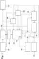
- Fig. 1shows a schematic representation of an embodiment of the system according to the invention, which is intended for arrangement and use in a motor vehicle (not shown).
- the sensor fusion system shownis designed, for example, to determine the position of the motor vehicle. All elements or components included in the system, or the basic system or the correction systems, are illustrated as functional blocks and their interaction with one another is shown.
- the sensor fusion systemincludes an inertial navigation system 101, which is designed such that it can detect at least the accelerations along a first, a second and a third axis as well as at least the rotation rates around the first, the second and the third axis.
- the first axiscorresponds, for example, to the longitudinal axis of the motor vehicle
- the second axiscorresponds to the transverse axis of the motor vehicle
- the third axiscorresponds to the vertical axis of the motor vehicle.
- These three axesform a Cartesian coordinate system, the so-called motor vehicle coordinate system.
- Inertial navigation system 101forms, for example, the so-called base system, the measured values of which are corrected using the so-called correction systems described below.
- the correction systemsare odometry navigation system 103 and satellite navigation system 104.
- the sensor fusion systemalso has a so-called strapdown algorithm unit 102, in which a so-called strapdown algorithm is carried out, by means of which the measured values from the inertial sensor navigation system 101 are converted into position data, among other things.
- the measured values from the inertial sensor navigation system 101which naturally describe accelerations, are integrated twice over time.
- An alignment of the motor vehicleis also carried out by means of two Integration of the corresponding measured values from inertial sensor navigation system 101 over time.
- the orientation and speed of the motor vehicleare also determined by means of a simple integration over time.
- strapdown algorithm unit 102compensates for a Coriolis force acting on inertial sensor navigation system 101.
- the output data from strapdown algorithm unit 102therefore include the following physical quantities: the speed, the acceleration and the rate of rotation of the motor vehicle, for example with respect to the three axes of the motor vehicle coordinate system mentioned and, for example, additionally in each case with respect to a world coordinate system that is suitable for describing the orientation or dynamic quantities of the motor vehicle in the world.
- the world coordinate system mentionedis a GPS coordinate system.
- the output data from strapdown algorithm unit 102includes the position with respect to the motor vehicle coordinate system and the orientation with respect to the world coordinate system.
- the output data from strapdown algorithm unit 102has the variances as information about the data quality of the above-mentioned physical quantities. These variances are not calculated in strapdown algorithm unit 102, for example, but are only used and forwarded by it.
- the above-mentioned physical quantities calculated by strapdown algorithm unit 102are output via output module 112 and made available to other motor vehicle systems.
- the sensor fusion systemalso includes odometry navigation system 103 in the form of wheel speed sensors for each wheel of the motor vehicle.
- odometry navigation system 103in the form of wheel speed sensors for each wheel of the motor vehicle.
- thisis a four-wheeled motor vehicle with four wheel speed sensors, each of which detects the speed of the wheel assigned to it and its direction of rotation.
- odometry navigation system 103includes a steering angle sensor element that detects the steering angle of the motor vehicle.
- odometry navigation system 103for example, uses fusion filter 105 to provide a starting speed or provides start-up speed information, at least when starting or switching on or initializing the sensor fusion system.
- the sensor fusion system shown as an examplehas satellite navigation system 104, which is designed such that it determines the distance between an assigned satellite and the motor vehicle as well as the speed between the assigned satellite and the motor vehicle.
- satellite navigation system 104provides a starting position or starting position information, for example, according to fusion filter 105, at least when starting or switching on or initializing the sensor fusion system.
- the sensor fusion systemalso includes fusion filter 105.
- Fusion filter 105provides a fusion data set 106 in the course of the joint evaluation of the measurement data from odometry navigation system 103, satellite navigation system 104 and inertial sensor navigation system 101.
- Fusion data set 106has the recorded measurement data from the different sensor systems, wherein fusion data set 106 additionally includes, for example, error values and variances associated with the error values, which describe the data quality.
- the measurement data or values from the inertial sensor navigation system 101are stored for a predetermined period of time during operation of the motor vehicle in an electronic data storage device 113 provided for this purpose by the fusion filter 105.
- the inertial navigation system 101represents the so-called basic system, while the odometry navigation system 103 and the satellite navigation system 104 represent the so-called correction systems, whose measurement values are used to correct the measurement values of the basic system. This ensures that values that were at least apparently recorded at an identical point in time can always be compared.
- Fusion data set 106 provided by fusion filter 105includes, for example, the quantitative errors of the base system determined by means of the plausibility-checked measured values of the correction systems.
- Strapdown algorithm unit 102now corrects the measured values of the base system using fusion data set 106.
- Fusion data set 106is calculated by fusion filter 105 from the measured values of odometry navigation system 103, satellite navigation system 104 and inertial navigation system 101.
- Fusion filter 105is designed, for example, as an error-state-space Kalman filter, i.e. as a Kalman filter, which in particular carries out a linearization of the measured values and in which the quantitative error values of the measured values are calculated or estimated and which works sequentially and thereby corrects the measured values available in the respective functional step of the sequence.
- an error-state-space Kalman filteri.e. as a Kalman filter, which in particular carries out a linearization of the measured values and in which the quantitative error values of the measured values are calculated or estimated and which works sequentially and thereby corrects the measured values available in the respective functional step of the sequence.
- Fusion filter 105is designed such that it always asynchronously records the most current measurement values available from inertial navigation system 101, odometry navigation system 103 and satellite navigation system 104.
- the measurement valuesare passed via motor vehicle model unit 107 and orientation model unit 109.
- Motor vehicle model unit 107is designed such that it calculates at least the speed along a first axis, the speed along a second axis and the rotation rate about a third axis from the measured values of odometry navigation system 103 and provides these to fusion filter 105.
- the exemplary sensor fusion systemalso includes tire parameter estimation unit 110, which is designed to calculate at least the radius, for example the dynamic radius, of all wheels and additionally the slip stiffness and the slip stiffness of all wheels and provides these motor vehicle model unit 107 as additional input variables.
- Tire parameter estimation unit 110is further designed such that it uses a substantially linear tire model to calculate the tire sizes.
- the exemplary input variables of tire parameter estimation unit 110are the measured values describing the wheel speeds and the steering angle, at least partially the output values of strapdown algorithm unit 102 and the variances determined by fusion filter 105.
- the exemplary sensor fusion systemalso includes GPS error detection and plausibility unit 111, which is designed such that it receives, for example, the measured values from satellite navigation system 104 and at least some measured values from strapdown algorithm unit 102 as input data and takes them into account in its calculations.
- GPS error detection and plausibility unit 111checks the measured values against a stochastic model adapted to satellite navigation system 104. If the measured values correspond to the model within a tolerance that takes the noise into account, they are checked for plausibility.
- GPS error detection and plausibility unit 111is additionally connected to fusion filter 105 at data level and transmits the plausibility-checked measured values to fusion filter 105.
- the sensor fusion systemalso has a standstill detection unit 108, which is designed such that it can detect a standstill of the motor vehicle and, in the event of a detected standstill of the motor vehicle, provides at least fusion filter 105 with information from a standstill model.
- the information from a standstill modeldescribes that the rotation rates around all three axes have the value zero and the speeds along all three axes have the value zero.
- Standstill detection unit 108is designed, for example, such that it uses the measured values of the wheel speed sensors of odometry navigation system 103 and the measured values of inertial navigation system 101 as input data.
- the sensor fusion systemuses, for example, a first group of measured values that refer to a motor vehicle coordinate system and additionally a second group of measured values that refer to a world coordinate system, wherein the world coordinate system is used to describe the orientation and dynamic variables of the motor vehicle.
- An orientation angle between the motor vehicle coordinate system and the world coordinate systemis determined by means of the orientation model unit 109.
- Alignment model unit 109uses all of the output data from strapdown algorithm unit 102.
- Alignment model unit 109is designed, for example, such that, in addition to the alignment angle, it calculates information about the data quality of the alignment angle in the form of a variance and provides fusion filter 105.
- Fusion filter 105uses the orientation angle and the variance of the orientation angle in its calculations, the results of which it forwards to strapdown algorithm unit 102 via fusion data set 106.
- Fusion filter 105thus records the measurement data from inertial navigation system 101, the base system, as well as from odometry navigation system 103 and from satellite navigation system 104, the correction systems.
- fusion filter 105is dependent on the physical quantities described directly and indirectly in the measured values of base system 101, which are corrected using measured values from correction systems 103 and 104 or whose error values are determined using measured values from correction systems 103 and 104.
- the physical quantities indirectly described in the measured values of base system 101such as the position and speed of the vehicle, cannot yet be determined, starting values are determined from the measured values of correction systems 103 and 104.
- Odometry navigation system 103determines, for example, a speed of the vehicle and makes this available to fusion filter 105 as a starting value for determining the speed. Likewise, a measurement inaccuracy inherent in the odometry navigation system 103 is passed on to the fusion filter 105 as a starting value for the error value of the speed. As soon as the satellite navigation system 104 has made an initial determination of the position, the position determined in this way is also passed on to the fusion filter 105 as a starting value for the position. At the same time, a variance based on the measurement inaccuracy of the determined position is output to the fusion filter 105 as an error value of the determined position.
- the position determined as the starting value and the measurement inaccuracy of the positionare determined as part of a preprocessing of the measured values by the satellite navigation system 104.
- the speed determined as the starting valueis also determined as part of a preprocessing by the odometry navigation system 103, but not the measurement inaccuracy used as the starting value for the error value. This comes, for example, from the sensor specifications of the individual wheel speed sensors. Thus, all the information required for correct functioning is available to the fusion filter 105 during initialization.
- Fig. 2shows an example of another possible form of a sensor fusion system, which can also be used for position determination is designed in a motor vehicle (not shown).
- the sensor fusion systemcomprises, for example, inertial navigation system 201, satellite navigation system 204 and odometry navigation system 203 as different sensor systems.
- Inertial navigation system 201, satellite navigation system 204 and odometry navigation system 203output measured values that directly or indirectly describe physical quantities, namely a position, a speed, an acceleration, an orientation, a yaw rate or a yaw acceleration, to fusion filter 205.
- the measured valuesare output via a vehicle data bus, for example via a so-called CAN bus.
- satellite navigation system 204outputs its measured data in raw data form.
- the central element in determining the position of the motor vehicleis the inertial navigation system 201, which is a so-called MEMS-IMU (Micro-Electro-Mechanical-System-Inertial Measurement Unit) in combination with the strapdown algorithm unit 207, since this is assumed to be error-free, i.e. it is assumed that the values of the inertial navigation system 201 always correspond to their stochastic model, that they only have noise influences and are thus free of external or random errors or disturbances.
- the noise and remaining, unmodeled errors of the inertial navigation system 201such as non-linearity, are assumed to be mean-free, stationary and normally distributed (so-called Gaussian white noise) over the measurement range.
- Inertial navigation system 201comprises three rotation rate sensors that are orthogonal to one another and three acceleration sensors that are orthogonal to one another.
- Satellite navigation system 204comprises a GPS receiver, which first measures the distance to the receivable GPS satellites via the satellite signal propagation time and also calculates the distance from the change in the satellite signal propagation time and In addition, the distance traveled by the motor vehicle is determined from the change in the number of wavelengths of the satellite signals.
- Odometry navigation system 203comprises a wheel speed sensor on each wheel of the motor vehicle and a steering angle sensor. The wheel speed sensors each determine the wheel rotational speed of the wheel assigned to them and the steering angle sensor determines the steering angle.
- Inertial navigation system 201outputs its measured values to preprocessing unit 206 of inertial sensor navigation system 201.
- Preprocessing unit 206now corrects the measured values or the physical quantities described therein using correction values that preprocessing unit 206 receives from fusion filter 205.
- the measured values corrected in this way or the physical quantities described thereinare passed on to strapdown algorithm unit 207.
- Strapdown algorithm unit 207now uses the corrected measurement data or values from preprocessing unit 206 to determine the position. This position determination is a so-called dead reckoning based on inertial navigation system 201. For this purpose, the corrected measurement values output by preprocessing unit 206 or the physical quantities described therein are continuously integrated or added up over time. Strapdown algorithm unit 207 also compensates for a Coriolis force acting on inertial sensor navigation system 201, which can affect the measurement data from inertial navigation system 201. To determine the position, strapdown algorithm unit 207 carries out a double integration of the measurement values recorded by inertial navigation system 201, which describe accelerations, over time. This enables an update of a previously known position and an update of a previously known orientation of the motor vehicle.
- strapdown algorithm unit 207To determine a speed or a rotation rate of the motor vehicle, strapdown algorithm unit 207 performs a simple integration of the measurement data acquired by inertial sensor navigation system 201 or values over time. Furthermore, strapdown algorithm unit 207 also corrects the determined position using corresponding correction values from fusion filter 205. In this example, fusion filter 205 only carries out the correction indirectly via strapdown algorithm unit 207. The measured values or physical quantities determined and corrected by strapdown algorithm unit 207, i.e. the position, speed, acceleration, orientation, angular rate and rotational acceleration of the motor vehicle, are now fed to output module 212 and to fusion filter 205.
- strapdown algorithm executed by strapdown algorithm unit 207is computationally only slightly complex and can therefore be implemented as a real-time capable basic system. It represents a process sequence for integrating the measured values from inertial navigation system 201 on speed, orientation and position and does not include any filtering, so that an almost constant latency and group delay is obtained.
- the term basic systemdescribes the sensor system whose measurement data or values are corrected using the measurement data or values of the other sensor systems, the so-called correction systems.
- the correction systemsare the odometry navigation system 203 and the satellite navigation system 204.
- Inertial navigation system 201preprocessing unit 206 of inertial sensor navigation system 201 and strapdown algorithm unit 207 together form, for example, the so-called basic system, to which fusion filter 205 is also counted proportionally.
- Output module 212forwards the physical quantities determined and corrected by strapdown algorithm unit 207 to any other systems of the motor vehicle.
- the measured values recorded by satellite navigation system 204are, for example, first passed on in the form of sensor signals via a so-called UART data connection to pre-processing unit 208 of satellite navigation system 204.
- Pre-processing unit 208determines a position and a speed of the motor vehicle in the GPS coordinate system from the measured values output by satellite navigation system 204, which represent GPS raw data and also include a description of the orbit of the GPS satellite sending the GPS signals.
- Satellite navigation system 204also determines a relative speed of the motor vehicle to the GPS satellites from which GPS signals are received.
- Pre-processing unit 208also corrects a time error contained in the measured values of a receiver clock of satellite navigation system 204, which is caused by a drift of the receiver clock, and by means of a correction model, the changes in the signal propagation time and the signal path caused by atmospheric effects on the GPS signals sent by the GPS satellites.
- the correction of the time error and the atmospheric influencesis carried out by means of fusion filter 205 using correction values received via the CAN bus.
- Satellite navigation system 204is also assigned to plausibility module 209, which checks the plausibility of the measured values of the physical quantities output by preprocessing unit 208, i.e. the physical quantities of the position and the speed of the motor vehicle.
- the measurement data or values checked for plausibility by plausibility module 209are then output to fusion filter 205.
- the systemalso includes pre-processing unit 210 of odometry navigation system 203, which receives the measured values recorded by odometry navigation system 203 via the CAN bus.
- the measured values recordedare the measured values of the individual wheel speed sensors and the measured values of the steering angle sensor.
- Pre-processing unit 210determines the position and the Orientation of the motor vehicle in the motor vehicle coordinate system. Furthermore, the speed, acceleration, yaw rate and rotational acceleration of the motor vehicle are determined, also in the motor vehicle coordinate system.
- preprocessing unit 210corrects the measurement data or values obtained from odometry navigation system 203 using correction values obtained from fusion filter 205.
- Odometry navigation system 203is also assigned to plausibility module 211, which checks the plausibility of the measured values output by preprocessing unit 210, i.e. the position, orientation, speed, acceleration, yaw rate and rotational acceleration of the motor vehicle. Since the disturbances in the measured values of odometry navigation system 203 are often random, environmentally caused disturbances that do not correspond to white noise, e.g. in the case of comparatively large wheel slip, the measured values determined by inertial navigation system 201 and by satellite navigation system 204 are used to check the plausibility of the measured values of odometry navigation system 203. Firstly, the measured values are compared with an assigned, sensor-specific model, which takes measurement uncertainties such as noise influences into account.
- the measured valuescorrespond to the model within the given limit values or tolerance ranges. If the measured values correspond to the model within the given limit values or tolerance ranges, an initial plausibility check is carried out here and the values thus checked for plausibility are further processed. The plausibility-checked values are then passed on to fusion filter 205. If a plausibility check of these measured values cannot be carried out, the corresponding measured values are discarded and not processed further.
- the individual modules plausibility module 209 and plausibility module 211together form a plausibility module within the meaning of the invention with the proportional inclusion of fusion filter 205.
- Fusion filter 205is designed as an error-state space Kalman filter.
- the main task of Fusion filter 205is designed, for example, to correct the measured values of the base system, i.e., inertial navigation system 201, using measured values from odometry navigation system 203 and satellite navigation system 204, which represent the correction systems, or to output corresponding correction values to strapdown algorithm unit 207. Since inertial navigation system 201 is assumed, for example, to be free of random errors and external disturbances, the measured values of inertial navigation system 201 are subject exclusively to white noise.
- the measured values of inertial navigation system 201are stored in an electronic data storage device (not shown) over a period of 25 measurement epochs. This ensures that measured values from the inertial navigation system 201 are available for plausibility checking, correction or merging for both the measured values from the odometry navigation system 203 and the satellite navigation system 204, which were recorded at an identical point in time.
- fusion filter 205is a so-called error state space Kalman filter, only the quantitative error values of the measured values are determined and corresponding corrections are carried out. This simplifies and accelerates the fusion of the measured values from inertial navigation system 201, odometry navigation system 203 and satellite navigation system 204 into a common fusion data set carried out by fusion filter 205. This enables real-time position determination and correction of the position determination.
- starting valuesare determined from the measured values of the odometry navigation system 203 and the satellite navigation system 204 for those physical quantities that are only indirectly described in the measured values of the inertial navigation system 201, namely the speed, the position, the receiver clock error of satellite navigation system 204 and the receiver clock error drift of satellite navigation system 204.
- the starting values for the error valuesare determined as variances based on the measurement inaccuracies of satellite navigation system 204 and of odometry navigation system 203.
- the Fig. 2The system shown represents a so-called virtual sensor, whereby the inertial navigation system 201, odometry navigation system 203 and satellite navigation system 204 are not components of the virtual sensor.
- a virtual sensoris a system which always generates the same output data or outputs regardless of the type of sensor systems integrated - in this case, inertial navigation system 201, odometry navigation system 203 and satellite navigation system 204. It is not clear from the output data or outputs which sensor systems are integrated into the system.
Landscapes
- Engineering & Computer Science (AREA)
- Radar, Positioning & Navigation (AREA)
- Remote Sensing (AREA)
- Physics & Mathematics (AREA)
- General Physics & Mathematics (AREA)
- Automation & Control Theory (AREA)
- Manufacturing & Machinery (AREA)
- Navigation (AREA)
- Position Fixing By Use Of Radio Waves (AREA)
Description
Translated fromGermanDie Erfindung betrifft ein Verfahren zur Initialisierung eines Sensorfusionssystems gemäß Anspruch 1 sowie ein System zur Initialisierung eines Sensorfusionssystems gemäß Anspruch 5.The invention relates to a method for initializing a sensor fusion system according to claim 1 and a system for initializing a sensor fusion system according to claim 5.
Alle Messdaten sind prinzipiell fehlerbehaftet und in vielen Fällen ist zudem eine durchgängige Verfügbarkeit der Messdaten nicht gegeben. Neben der Abhängigkeit der Messdaten von sensorinhärenten Eigenschaften sind die Messdaten darüber hinaus oftmals auch von Umgebungsbedingungen abhängig. Sensorfehler bzw. Messfehler lassen sich dabei in quasistationäre, über mehrere Messungen konstante Anteile, wie z.B. einen sog. Offset, und statistische, von Messung zu Messung zufällige Anteile, wie z.B. Rauschen, unterteilen. Während die zufälligen Anteile prinzipiell nicht deterministisch korrigierbar sind, lassen sich quasistationäre Fehler im Allgemeinen bei gegebener Beobachtbarkeit korrigieren. Nicht korrigierbare signifikante Fehler lassen sich bei gegebener Erkennbarkeit üblicherweise zumindest vermeiden. Weiterhin sind Fehler in den Messdaten oftmals erst nach dem Erfassen und Auswerten einer Reihe von Vergleichsmessungen identifizierbar.All measurement data is in principle subject to errors and in many cases there is no consistent availability of the measurement data. In addition to the dependence of the measurement data on sensor-inherent properties, the measurement data is also often dependent on environmental conditions. Sensor errors or measurement errors can be divided into quasi-stationary components that are constant over several measurements, such as a so-called offset, and statistical components that are random from measurement to measurement, such as noise. While the random components cannot in principle be corrected deterministically, quasi-stationary errors can generally be corrected if they are observable. Uncorrectable significant errors can usually at least be avoided if they are detectable. Furthermore, errors in the measurement data can often only be identified after a series of comparative measurements have been recorded and evaluated.
Im Stand der Technik sind in diesem Zusammenhang bereits Sensorfusionsverfahren bekannt, welche üblicherweise auch dazu geeignet sind, Messdaten von unterschiedlichen Sensoren bzw. Sensorsystemen zu korrigieren bzw. zu filtern. Insbesondere im Automotive-Bereich sind dabei besondere Anforderungen zu berücksichtigen, da eine Vielzahl von unterschiedlichen Sensoren eine gemeinsame Umfeldsituation bzw. einen Kraftfahrzeugzustand mittels unterschiedlicher Messprinzipien erfasst und diese Umfeldsituation bzw. diesen Kraftfahrzeugzustand mittels einer Vielzahl unterschiedlicher Messdaten beschreibt. Für eine im Automotive-Bereich anwendbare Sensorfusion ist somit eine möglichst große Robustheit gegen zufällige Störungen sowie eine Erkennung und Kompensation von systematischen Fehlern gefordert. Ebenso sind zeitliche Einflüsse auf die Messdaten zu korrigieren und temporäre Ausfälle oder die Nichtverfügbarkeit von Sensoren zu überbrücken.In this context, sensor fusion methods are already known in the state of the art, which are usually also suitable for correcting or filtering measurement data from different sensors or sensor systems. In the automotive sector in particular, special requirements must be taken into account, since a large number of different sensors record a common environmental situation or a vehicle state using different measurement principles and describe this environmental situation or this vehicle state using a large number of different measurement data. For a sensor fusion that can be used in the automotive sector, the greatest possible robustness against random disturbances and a Detection and compensation of systematic errors is required. Temporal influences on the measurement data must also be corrected and temporary failures or the unavailability of sensors must be bridged.
Die
Aus der
Die
Die
Die
Die
- ein Trägheitsnavigationssystem (INS) zum Erzeugen von Fahrzeugzustandsschätzungen basierend auf der Beschleunigungs- und Winkelgeschwindigkeitsmessung von der IMU;
- eine Hilfsmess-(Aux)-Einheit zum Erzeugen von Hilfsmessdaten, die einen analytischen Zustand beinhalten, der aus dem mechanischen Zustand eines Fahrzeugs abgeleitet wird;
- eine Global Positioning System (GPS)-Einheit zum Empfangen von GPS-Satellitensignalen von mehreren GPS-Satelliten über eine GPS-Antenne, um GPS-Messausgaben zu erzeugen, die eine absolute Position und Geschwindigkeit des Fahrzeugs anzeigen; und
- ein Kalman-Filter, das die Zustandsschätzungen des INS, die Hilfsmessdaten der Aux-Einheit und die GPS-Messausgaben der GPS-Einheit kombiniert und daran eine Kalman-Filterverarbeitung durchführt;
- wobei die in der Aux-Einheit enthaltene analytische Bedingung eine Beziehung zwischen einer seitlichen Richtungsgeschwindigkeit eines Fahrzeugs, einem Abstand der Sensorposition in Bezug auf eine Hinterradachse und einer Winkelgeschwindigkeit in Bezug auf die z-Achse eines Fahrzeugs ist.
- an inertial navigation system (INS) for generating vehicle state estimates based on the acceleration and angular velocity measurements from the IMU;
- an auxiliary measurement (aux) unit for generating auxiliary measurement data including an analytical condition derived from the mechanical condition of a vehicle;
- a Global Positioning System (GPS) unit for receiving GPS satellite signals from multiple GPS satellites via a GPS antenna to generate GPS measurement outputs indicating an absolute position and speed of the vehicle; and
- a Kalman filter that combines the state estimates of the INS, the auxiliary measurement data of the Aux unit, and the GPS measurement outputs of the GPS unit and performs Kalman filter processing on them;
- wherein the analytical condition included in the auxiliary unit is a relationship between a lateral direction velocity of a vehicle, a distance of the sensor position with respect to a rear wheel axis, and an angular velocity with respect to the z-axis of a vehicle.
Die im Stand der Technik bekannten, gattungsgemäßen Verfahren und Sensorsysteme sind jedoch insofern nachteilbehaftet, als dass bei der Initialisierung dieser Sensorsysteme auftretende Probleme nicht gebührend berücksichtigt werden. Bei der Initialsierung ist eine Vielzahl physikalischer Größen zunächst nicht bekannt ist, da unmittelbar keine Messdaten zu diesen Größen erfasst werden können. Gleichzeitig können die möglichen Fehler dieser physikalischen Größen derart groß sein, dass für eine gattungsgemäße Sensordatenfusion angenommene Linearisierungsbedingungen im Fusionsfilter ungültig werden, wodurch das Fusionsfilter und die von ihm ausgeführte Fehlerschätzung instabil werden. Dies führt zum Versagen der Sensorfusion.However, the generic methods and sensor systems known in the prior art have disadvantages in that problems that arise during the initialization of these sensor systems are not adequately taken into account. During initialization, a large number of physical quantities are initially unknown because no measurement data for these quantities can be recorded immediately. At the same time, the possible errors in these physical quantities can be so large that linearization conditions assumed for a generic sensor data fusion become invalid in the fusion filter, which makes the fusion filter and the error estimation it performs unstable. This leads to the failure of the sensor fusion.
Es ist daher eine Aufgabe der Erfindung, ein verbessertes Verfahren zur Initialisierung eines Sensorfusionssystems vorzuschlagen.It is therefore an object of the invention to propose an improved method for initializing a sensor fusion system.
Diese Aufgabe wird erfindungsgemäß durch das Verfahren zur Initialisierung eines Sensorfusionssystems gemäß Anspruch 1 gelöst.This object is achieved according to the invention by the method for initializing a sensor fusion system according to claim 1.
Die Erfindung betrifft ein Verfahren zur Initialisierung eines Sensorfusionssystems beim Hochfahren oder Starten des Sensorfusionssystems, wobei das Sensorfusionssystem ein Basissystem und mindestens ein Korrektursystem umfasst,
- wobei vom Basissystem und vom mindestens einen Korrektursystem jeweils Messwerte erfasst werden,
- wobei die Messwerte direkt oder indirekt physikalische Größen beschreiben, wobei die Messwerte jeweils mit Fehlerwerten behaftet sind, wobei die Fehlerwerte Abweichungen der Messwerte von den beschriebenen physikalischen Größen beschreiben, wobei zumindest die in den Messwerten des Basissystems indirekt beschriebenen physikalischen Größen sowie deren Fehlerwerte während der Initialisierung des Sensorfusionssystems nicht bestimmbar sind,
- wobei die Messwerte nach Abschluss der Initialisierung kontinuierlich zu einem Fusionsdatensatz fusioniert werden und wobei für zumindest eine der in den Messwerten des Basissystems indirekt beschriebenen physikalischen Größen sowie deren Fehlerwerte Startwerte aus den Messwerten des mindestens einen Korrektursystems während der Initialisierung bestimmt werden.
- whereby measured values are recorded by the base system and by at least one correction system,
- wherein the measured values directly or indirectly describe physical quantities, wherein the measured values are each subject to error values, wherein the error values describe deviations of the measured values from the described physical quantities, wherein at least the physical quantities indirectly described in the measured values of the basic system and their error values cannot be determined during the initialization of the sensor fusion system,
- wherein the measured values are continuously fused to form a fusion data set after completion of the initialization, and wherein start values are determined from the measured values of the at least one correction system during the initialization for at least one of the physical quantities indirectly described in the measured values of the base system and their error values.
Daraus ergibt sich der Vorteil, dass beim Hochfahren bzw. Starten des Sensorfusionssystems von Anfang an Messwerte für alle vom Sensorfusionssystem benötigten physikalischen Größen vorhanden sind. Somit ist das Sensorfusionssystem im Wesentlichen von Anfang an weitestgehend voll funktionsfähig.This has the advantage that when the sensor fusion system is booted up or started, measured values for all physical quantities required by the sensor fusion system are available right from the start. This means that the sensor fusion system is essentially fully functional right from the start.
Die bekannten Sensorfusionssysteme umfassen dabei üblicherweise ein sog. Fusionsfilter, das als rekursives Filter arbeitet. Die bedeutet also, dass das Fusionsfilter aus Messwerten aus der Vergangenheit auf die Gegenwart schließt. Beim Initialisieren des Sensorfusionssystems liegen aber noch keine Messwerte aus der Vergangenheit vor, weshalb das erfindungsgemäße Verfahren Startwerte aus den Messwerten des mindestens einen Korrektursystems heranzieht, um dem Fusionsfilter die Messwerte als Startwerte zur Verfügung zu stellen.The known sensor fusion systems usually include a so-called fusion filter, which works as a recursive filter. This means that the fusion filter draws conclusions about the present from measured values from the past. When the sensor fusion system is initialized, however, no measured values from the past are available, which is why the method according to the invention Uses starting values from the measured values of at least one correction system in order to provide the measured values to the fusion filter as starting values.
Die Erfindung nutzt den Umstand, dass das mindestens eine Korrektursystem bei der Initialisierung üblicherweise im Wesentlichen sofort Messwerte erfasst und zur Verfügung stellen kann.The invention makes use of the fact that the at least one correction system can usually record and provide measured values essentially immediately upon initialization.
Das Sensorfusionssystem fusioniert im Betrieb üblicherweise die Messdaten des Basissystems sowie des Korrektursystems zu einem gemeinsamen Fusionsdatensatz, der gegenüber den einzelnen Messdaten zuverlässiger und präziser ist und insbesondere mittels einer Fehlerschätzung eine Bewertung der Genauigkeit bzw. Zuverlässigkeit der fusionierten Messdaten gestattet.During operation, the sensor fusion system typically fuses the measurement data of the base system and the correction system into a common fusion data set, which is more reliable and precise than the individual measurement data and, in particular, allows an assessment of the accuracy or reliability of the fused measurement data by means of an error estimate.
Der Begriff "während der Initialisierung des Sensorfusionssystems" wird im Sinne der Erfindung gleichbedeutend mit "während des Hochfahrens des Sensorfusionssystems" bzw. "während des Startens des Sensorfusionssystems" verwendet und bezeichnet den Zeitrahmen des Initialisierungsprozesses des Sensorfusionssystems. Die Initialisierung wird erfindungsgemäß als abgeschlossen betrachtet, wenn das Fusionsfilter vom Basissystem alle zu seiner korrekten Funktionsweise benötigten Informationen, also sowohl die in den Messwerten des Basissystem direkt als auch indirekt beschriebenen physikalischen Größen, bereitgestellt bekommt und die Messwerte der Korrektursysteme nur noch zur Bestimmung der Fehlerwerte des Basissystems benötigt.The term "during the initialization of the sensor fusion system" is used in the sense of the invention as synonymous with "during the startup of the sensor fusion system" or "during the start of the sensor fusion system" and refers to the time frame of the initialization process of the sensor fusion system. According to the invention, the initialization is considered to be completed when the fusion filter receives all the information required for its correct functioning from the base system, i.e. both the physical quantities described directly and indirectly in the measured values of the base system, and only needs the measured values of the correction systems to determine the error values of the base system.
Bevorzugt wird das erfindungsgemäße Verfahren nicht nur bei der ersten Initialisierung des Sensorfusionssystems ausgeführt sondern auch bei einigen oder allen folgenden Reinitialisierungen.Preferably, the method according to the invention is carried out not only during the first initialization of the sensor fusion system but also during some or all subsequent reinitializations.
Die indirekt beschriebenen physikalischen Größen sowie insbesondere deren Fehlerwerte werden bevorzugt mittels physikalischer bzw. mathematischer Zusammenhänge aus den direkt gemessenen physikalischen Größen bestimmt. Ein Beispiel für eine indirekt beschriebene physikalische Größe ist etwa eine Geschwindigkeit, welche indirekt über eine Positionsänderung über die Zeit beschrieben ist. Die Position als physikalische Größe wird also direkt gemessen und anschließend wird aus der Änderung der Position mit fortlaufender Zeit mittels Differentiation die Geschwindigkeit bestimmt.The indirectly described physical quantities and in particular their error values are preferably determined by means of physical or mathematical relationships from the directly measured physical quantities. An example of a An indirectly described physical quantity is a speed, which is indirectly described by a change in position over time. The position as a physical quantity is therefore measured directly and then the speed is determined from the change in position over time using differentiation.
Bevorzugt ist es vorgesehen, dass für die Erstellung des gemeinsamen Fusionsdatensatzes nur Messwerte mit einem identischen Zeitstempel herangezogen werden. Die Messwerte beschreiben also dieselbe physikalische Größe zum selben Zeitpunkt. Somit sind die herangezogenen Messwerte idealerweise identisch bzw. müssen es idealerweise sein. Daraus ergibt sich der Vorteil, dass Fehlerwerte der Messwerte besser und zuverlässiger identifizierbar sind. Somit verbessert sich auch die Genauigkeit bzw. Zuverlässigkeit des Fusionsdatensatzes.Preferably, only measured values with an identical time stamp are used to create the common fusion data set. The measured values therefore describe the same physical quantity at the same time. The measured values used are therefore ideally identical, or ideally must be. This has the advantage that error values in the measured values can be identified better and more reliably. This also improves the accuracy and reliability of the fusion data set.
Bevorzugt ist es vorgesehen, dass der gemeinsame Fusionsdatensatz zumindest die Fehlerwerte des Basissystems umfasst, wobei die Fehlerwerte des Basissystems durch Vergleich mit den Messwerten des mindestens einen Korrektursystems und ggf. durch eine Gewichtung der Messwerte des Basissystems gegen die Messwerte des mindestens einen Korrektursystems bestimmt werden.Preferably, it is provided that the common fusion data set comprises at least the error values of the base system, wherein the error values of the base system are determined by comparison with the measured values of the at least one correction system and, if necessary, by weighting the measured values of the base system against the measured values of the at least one correction system.
Weiterhin ist es bevorzugt, dass das mindestens eine Korrektursystem die Startwerte und die Korrekturwerte mittels jeweils einer eigenständigen Messwerteverarbeitung bestimmt. Dazu kann das mindestens eine Korrektursystem beispielsweise eine eigenständige und vom Sensorfusionssystem weitestgehend unabhängige Vorverarbeitung der Messwerte umfassen. Insbesondere im Rahmen einer engen Kopplung, die auch als sog. tightly coupling bekannt ist, bestimmt das mindestens eine Korrektursystem zunächst selbständig die Werte derjenigen physikalischen Größen, die durch die Messwerte des mindestens einen Korrektursystems beschrieben werden. Im Rahmen dieser Vorverarbeitung ist dann auch bereits eine erste Korrektur der Messwerte des mindestens einen Korrektursystems möglich.Furthermore, it is preferred that the at least one correction system determines the starting values and the correction values by means of an independent measurement value processing. For this purpose, the at least one correction system can, for example, comprise an independent preprocessing of the measurement values that is largely independent of the sensor fusion system. In particular within the framework of a close coupling, which is also known as so-called tightly coupling, the at least one correction system first independently determines the values of those physical quantities that are described by the measurement values of the at least one correction system. Within the framework of this preprocessing, a first correction of the measurement values of the at least one correction system is then also possible.
Erfindungsgemäß ist das Basissystem ein Trägheitsnavigationssystem und das mindestens eine Korrektursystem ein globales Satellitennavigationssystem und/oder ein Odometrienavigationssystem. Damit ist die vorliegende Erfindung insbesondere zu Navigationszwecken und für Navigationssysteme, bevorzugt in Kraftfahrzeugen, geeignet. Das Sensorfusionssystem bestimmt somit also die Position, insbesondere die Position eines Kraftfahrzeugs, aus den Messwerten. Bei dem globalen Satellitennavigationssystem kann es sich beispielsweise um ein sog. GPS-Navigationssystem handeln. Das Odometrienavigationssystem bestimmt zunächst die Geschwindigkeit z.B. über den bekannten Abrollumfang der Kraftfahrzeugreifen und ermöglicht somit eine Positionsbestimmung unter Berücksichtigung des Lenkwinkels im Rahmen einer Koppelnavigation. Besonders zweckmäßig ist es, dass das Satellitennavigationssystem mindestens zwei Satellitensignalempfänger umfasst. Dadurch verbessert sie die Qualität der erfassten Satellitensignale und somit die Zuverlässigkeit und Genauigkeit des Satellitennavigationssystems.According to the invention, the base system is an inertial navigation system and the at least one correction system is a global satellite navigation system and/or an odometry navigation system. The present invention is therefore particularly suitable for navigation purposes and for navigation systems, preferably in motor vehicles. The sensor fusion system therefore determines the position, in particular the position of a motor vehicle, from the measured values. The global satellite navigation system can be a so-called GPS navigation system, for example. The odometry navigation system first determines the speed, e.g. via the known rolling circumference of the vehicle tires, and thus enables position determination taking the steering angle into account as part of dead reckoning. It is particularly expedient for the satellite navigation system to comprise at least two satellite signal receivers. This improves the quality of the detected satellite signals and thus the reliability and accuracy of the satellite navigation system.
Erfindungsgemäß werden die Startwerte für die Fehlerwerte als Varianzen auf Basis der Messungenauigkeiten des mindestens einen Korrektursystems bestimmt. Somit wird zunächst einmal dem Umstand Rechnung getragen, dass das Sensorfusionssystem bzw. das Fusionsfilter in der Regel auch Fehlerwerte bestimmt und hierzu auf das Vorhandensein von Messwerten angewiesen ist. Indem nun also die Varianzen der Messwerte des mindestens einen Korrektursystems als Startwerte für die Fehlerwerte herangezogen werden, kann dem Sensorfusionssystem bzw. dem Fusionsfilter auch diese Größe auf vergleichsweise einfache Art und Weise zur Verfügung gestellt werden.According to the invention, the starting values for the error values are determined as variances based on the measurement inaccuracies of the at least one correction system. This first of all takes into account the fact that the sensor fusion system or the fusion filter usually also determines error values and is dependent on the presence of measured values for this purpose. By using the variances of the measured values of the at least one correction system as starting values for the error values, this value can also be made available to the sensor fusion system or the fusion filter in a comparatively simple manner.
Insbesondere ist es bevorzugt, dass die Messungenauigkeiten dabei den Sensorspezifikationen bzw. einem Datenblatt der Sensoren des Basissysteme bzw. des mindestens einen Korrektursystems entnommen werden bzw. mittels Fehlerfortpflanzung bestimmt werden. Grundlage für die Bestimmung mittels Fehlerfortpflanzung ist die Eigenbewertung der Messgenauigkeit durch das Basissystem bzw. das mindestens eine Korrektursystem und die jeweilige Vorverarbeitung. Die Vorverarbeitung wird dabei üblicherweise ohnehin für bekannte Sensorfusionssysteme verwendet und kann somit ohne zusätzlichen Aufwand auch für das erfindungsgemäße Verfahren verwendet werden.In particular, it is preferred that the measurement inaccuracies are taken from the sensor specifications or a data sheet of the sensors of the basic system or the at least one correction system or are determined by means of error propagation. The basis for the determination by means of error propagation is the self-assessment of the measurement accuracy by the basic system or the at least one correction system. and the respective preprocessing. The preprocessing is usually used for known sensor fusion systems anyway and can therefore also be used for the method according to the invention without additional effort.
Erfindungsgemäß ist es vorgesehen, dass die in den Messwerten des Basissystems indirekt beschriebenen physikalischen Größen eine Geschwindigkeit und/oder eine Position und/oder einen Empfängeruhrfehler des globalen Satellitennavigationssystems und/oder eine Empfängeruhrfehlerdrift des globalen Satellitennavigationssystems umfassen. Diese Größen lassen sich direkt aus den Korrektursystemen bestimmen, insbesondere wenn es sich ein globales Satellitennavigationssystem und ein Odometrienavigationssystem handelt.According to the invention, it is provided that the physical quantities indirectly described in the measured values of the base system include a speed and/or a position and/or a receiver clock error of the global satellite navigation system and/or a receiver clock error drift of the global satellite navigation system. These quantities can be determined directly from the correction systems, in particular when it is a global satellite navigation system and an odometry navigation system.
Außerdem ist es bevorzugt, dass die Startwerte schrittweise aus den Messwerten des mindestens einen Korrektursystems bestimmt werden. Daraus ergibt sich der Vorteil, dass den Initialisierungsgeschwindigkeiten und ggf. weiteren Eigenschaften der unterschiedlichen Korrektursysteme Rechnung getragen werden kann, wodurch ein an die Korrektursysteme individuell angepasstes zeitliches Bereitstellen der Messwerte als Startwerte ermöglicht wird. Die Startwerte werden also in derjenigen zeitlichen Reihenfolge bereitgestellt, wie sie von den Korrektursystemen ausgegeben werden.It is also preferred that the starting values are determined step by step from the measured values of the at least one correction system. This has the advantage that the initialization speeds and possibly other properties of the different correction systems can be taken into account, which enables the measured values to be provided as starting values at a time that is individually adapted to the correction systems. The starting values are therefore provided in the same chronological order as they are output by the correction systems.
Außerdem ist es insbesondere bevorzugt, dass zuerst Startwerte aus den Messwerten des Odometrienavigationssystems bestimmt werden. Das Odometrienavigationssystem hat den Vorteil, dass es unmittelbar beim Start des Fahrzeugs bereits Raddrehsignale erfassen kann und somit unmittelbar beim Start des Fahrzeugs die Geschwindigkeit bestimmen kann. Zudem sind die Raddrehsignale von besonderer Bedeutung für die Fahrzeugsicherheit, da sie nicht nur zur Geschwindigkeitsbestimmung verwendet werden, sondern auch für unterschiedliche Fahrerassistenzsysteme, wie etwa ABS oder ESC, genutzt werden.In addition, it is particularly preferred that starting values are first determined from the measured values of the odometry navigation system. The odometry navigation system has the advantage that it can detect wheel rotation signals immediately when the vehicle starts and can therefore determine the speed immediately when the vehicle starts. In addition, the wheel rotation signals are of particular importance for vehicle safety, as they are not only used to determine the speed, but are also used for various driver assistance systems, such as ABS or ESC.
Erfindungsgemäß werden die Fehlerwerte mittels eines Error-State-Space-Filters, insbesondere mittels eines Error-State-Space-Kalman-Filters erkannt und korrigiert. Das Error-State-Space-Filter stellt dabei ein Fusionsfilter zur Fusion der Messwerte dar, insbesondere zur Fusion von normalverteilten Messwerten. Gleichzeitig schätzt bzw. bestimmt das Error-State-Space-Filter bevorzugt die Fehlerwerte zumindest des Basissystems. Bevorzugt handelt es sich bei dem Basissystem um ein Trägheitsnavigationssystem eines Kraftfahrzeugs. Mittels der Korrektursysteme können dann die Fehlerwerte und ggf. auch unbekannte Größen des Trägheitsnavigationssystems geschätzt bzw. bestimmt werden. Eine Besonderheit des Error-State-Space-Filters ist es also, dass anstelle der Sensorsignale bzw. der Messwerte lediglich Fehlerwerte inkrementell geschätzt bzw. bestimmt werden und anschließend korrigiert werden. Die Fehlerwerte haben nämlich eine signifikant niedrigere zeitliche Dynamik als die Messwerte selbst, wodurch eine weitgehende Entkopplung der Dynamik des Error-State-Space-Filters von den Eigenschaften des Basissystems bzw. des mindestens einen Korrektursystems,
wodurch eine weitgehende Entkopplung der Dynamik des Error-State-Space-Filters von den Sensoreigenschaften erreicht wird.According to the invention, the error values are detected and corrected by means of an error state space filter, in particular by means of an error state space Kalman filter. The error state space filter represents a fusion filter for fusing the measured values, in particular for fusing normally distributed measured values. At the same time, the error state space filter preferably estimates or determines the error values of at least the basic system. The basic system is preferably an inertial navigation system of a motor vehicle. The error values and possibly also unknown variables of the inertial navigation system can then be estimated or determined by means of the correction systems. A special feature of the error state space filter is that instead of the sensor signals or the measured values, only error values are incrementally estimated or determined and then corrected. The error values have a significantly lower temporal dynamic than the measured values themselves, which largely decouples the dynamics of the error state space filter from the properties of the basic system or the at least one correction system.
This results in a large-scale decoupling of the dynamics of the error state space filter from the sensor properties.
Eine weitere Besonderheit des Error-State-Space-Kalman-Filters ist es, dass durch die Anbringung einer Korrektur die geschätzten bzw. bestimmten Fehlerwerte nach jedem Arbeitszyklus des Error-State-Space-Kalman-Filters Null sind, wodurch ein sonst üblicher Prädiktionsschritt zur Vorhersage der Fehlerwerte im folgenden Arbeitszyklus entfällt, wodurch sich also der Rechenaufwand für das Error-State-Space-Kalman-Filter reduziert.Another special feature of the Error-State-Space Kalman filter is that by applying a correction, the estimated or determined error values are zero after each duty cycle of the Error-State-Space Kalman filter, which eliminates an otherwise usual prediction step for predicting the error values in the following duty cycle, thus reducing the computational effort for the Error-State-Space Kalman filter.
Die Erfindung betrifft weiterhin ein System zur Initialisierung eines Sensorfusionssystems beim Hochfahren oder Starten des Sensorfusionssystems, wobei das Sensorfusionssystem ein Basissystem und mindestens ein Korrektursystem umfasst, wobei das Basissystem und das mindestens eine Korrektursystem jeweils dazu ausgebildet sind, Messwerte zu erfassen, wobei die Messwerte direkt oder indirekt physikalische Größen beschreiben, wobei die Messwerte jeweils mit Fehlerwerten behaftet sind, wobei die Fehlerwerte Abweichungen der Messwerte von den beschriebenen physikalischen Größen beschreiben, wobei das Sensorfusionssystem derart ausgebildet ist, dass zumindest die in den Messwerten des Basissystems indirekt beschriebenen physikalischen Größen sowie deren Fehlerwerte während der Initialisierung des Sensorfusionssystems nicht bestimmbar sind, wobei das Sensorfusionssystem dazu ausgebildet ist, die Messwerte nach Abschluss der Initialisierung kontinuierlich zu einem Fusionsdatensatz zu fusionieren und wobei das Sensorfusionssystem dazu ausgebildet ist, für zumindest eine der in den Messwerten des Basissystems indirekt beschriebenen physikalischen Größen sowie deren Fehlerwerte Startwerte aus den Messwerten des mindestens einen Korrektursystems während der Initialisierung zu bestimmen. Das erfindungsgemäße System umfasst somit alle zur Ausführung des erfindungsgemäßen Verfahrens notwendigen Vorrichtungen.The invention further relates to a system for initializing a sensor fusion system when booting up or starting the sensor fusion system, wherein the sensor fusion system comprises a base system and at least one correction system, wherein the base system and the at least one correction system are each designed to record measured values, wherein the measured values directly or indirectly describe physical quantities, the measured values each having error values, the error values describing deviations of the measured values from the described physical quantities, the sensor fusion system being designed such that at least the physical quantities indirectly described in the measured values of the basic system and their error values cannot be determined during the initialization of the sensor fusion system, the sensor fusion system being designed to continuously fuse the measured values into a fusion data set after completion of the initialization, and the sensor fusion system being designed to determine start values from the measured values of the at least one correction system during the initialization for at least one of the physical quantities indirectly described in the measured values of the basic system and their error values. The system according to the invention thus comprises all devices necessary for carrying out the method according to the invention.
Bevorzugt ist es vorgesehen, dass das System dazu ausgebildet ist, auch bevorzugte Ausführungsformen des erfindungsgemäßen Verfahrens auszuführen.Preferably, the system is designed to also carry out preferred embodiments of the method according to the invention.
Weitere bevorzugte Ausführungsformen ergeben sich aus den Unteransprüchen und der nachfolgenden Beschreibung eines Ausführungsbeispiels an Hand von Figuren.Further preferred embodiments emerge from the subclaims and the following description of an embodiment with reference to figures.
Es zeigen
- Fig. 1
- beispielhaft eine mögliche Ausbildungsform eines erfindungsgemäßen Systems, welches zur Positionsbestimmung ausgebildet ist, in einem Kraftfahrzeug und
- Fig. 2
- beispielhaft eine weitere mögliche Ausbildungsform eines erfindungsgemäßen Systems, welches ebenfalls zur Positionsbestimmung ausgebildet ist, in einem Kraftfahrzeug.
- Fig. 1
- by way of example, a possible embodiment of a system according to the invention, which is designed for position determination, in a motor vehicle and
- Fig. 2
- by way of example, another possible embodiment of a system according to the invention, which is also designed for position determination, in a motor vehicle.
Das Sensorfusionssystem umfasst Trägheitsnavigationssystem 101, das so ausgebildet ist, dass es zumindest die Beschleunigungen entlang einer ersten, einer zweiten und einer dritten Achse sowie wenigstens die Drehraten um die erste, um die zweite und um die dritte Achse erfassen kann. Die erste Achse entspricht dabei beispielsgemäß der Längsachse des Kraftfahrzeugs, die zweite Achse entspricht der Querachse des Kraftfahrzeugs und die dritte Achse entspricht der Hochachse des Kraftfahrzeugs. Diese drei Achsen bilden ein kartesisches Koordinatensystem, das sog. Kraftfahrzeugkoordinatensystem.The sensor fusion system includes an
Trägheitsnavigationssystem 101 bildet beispielsgemäß das sog. Basissystem, dessen Messwerte mittels der im Folgenden beschriebenen sog. Korrektursysteme korrigiert werden. Die Korrektursysteme sind dabei Odometrienavigationssystem 103 und Satellitennavigationssystems 104.
Das Sensorfusionssystem weist weiterhin eine sog. Strapdown-Algorithmus-Einheit 102 auf, in welcher ein sog. Strapdown-Algorithmus durchgeführt wird, mittels dessen die Messwerte von Trägheitssensornavigationssystem 101 u.a. in Positionsdaten umgerechnet werden. Dazu werden die Messwerte von Trägheitssensornavigationssystem 101, welche naturgemäß Beschleunigungen beschreiben, zweimal über die Zeit integriert. Auch eine Ausrichtung des Kraftfahrzeugs wird mittels zweimaliger Integration der entsprechenden Messwerte von Trägheitssensornavigationssystem 101 über die Zeit bestimmt. Mittels einer Einfachintegration über die Zeit werden weiterhin die Ausrichtung und die Geschwindigkeit des Kraftfahrzeugs bestimmt. Außerdem kompensiert Strapdown-Algorithmus-Einheit 102 eine auf Trägheitssensornavigationssystem 101 wirkende Corioliskraft.The sensor fusion system also has a so-called
Die Ausgangsdaten von Strapdown-Algorithmus-Einheit 102 umfassen folglich die folgenden physikalischen Größen: die Geschwindigkeit, die Beschleunigung sowie die Drehrate des Kraftfahrzeugs, beispielsgemäß bezüglich der genannten drei Achsen des Kraftfahrzeugkoordinatensystems und beispielsgemäß zusätzlich jeweils bezogen auf ein Weltkoordinatensystem, das zur Beschreibung der Ausrichtung bzw. von dynamischen Größen des Kraftfahrzeugs auf der Welt geeignet ist. Beispielsgemäß handelt es sich bei dem genannten Weltkoordinatensystem um ein GPS-Koordinatensystem. Außerdem umfassen die Ausgangsdaten von Strapdown-Algorithmus-Einheit 102 die Position bezüglich des Kraftfahrzeugkoordinatensystems und die Ausrichtung hinsichtlich des Weltkoordinatensystems. Zusätzlich weisen die Ausgangsdaten von Strapdown-Algorithmus-Einheit 102 die Varianzen als Information über die Datenqualität der oben genannten physikalischen Größen auf. Diese Varianzen werden beispielgemäß nicht in Strapdown-Algorithmus-Einheit 102 berechnet, sondern nur von dieser verwendet und weitergeleitet. Die von Strapdown-Algorithmus-Einheit 102 berechneten o.g. physikalischen Größen werden über Ausgabemodul 112 ausgegeben und anderen Kraftfahrzeugsystemen zur Verfügung gestellt.The output data from
Das Sensorfusionssystem umfasst außerdem Odometrienavigationssystem 103 in Form von Raddrehzahlsensoren für jedes Rad des Kraftahrzeugs. Beispielgemäß handelt es sich um ein vierrädriges Kraftfahrzeug mit vier Raddrehzahlsensoren, die jeweils die Drehzahl des ihnen zugeordneten Rads sowie dessen Drehrichtung erfassen. Weiterhin umfasst Odometrienavigationssystem 103 ein Lenkwinkelsensorelement, das den Lenkwinkel des Kraftfahrzeugs erfasst. Zusätzlich stellt Odometrienavigationssystem 103 beispielsgemäß Fusionsfilter 105 eine Startgeschwindigkeit bzw. eine Startgeschwindigkeitsinformation bereit, zumindest beim Start bzw. Einschalten bzw. Initialisieren des Sensorfusionssystems.The sensor fusion system also includes
Darüber hinaus weist das beispielhaft dargestellte Sensorfusionssystem Satellitennavigationssystem 104 auf, welches so ausgebildet ist, dass es die Entfernung jeweils zwischen einem zugeordneten Satelliten und dem Kraftahrzeug sowie die Geschwindigkeit jeweils zwischen dem zugeordneten Satelliten und dem Kraftfahrzeug bestimmt. Zusätzlich stellt Satellitennavigationssystem 104 beispielsgemäß Fusionsfilter 105 eine Startposition bzw. Startpositionsinformation bereit, zumindest beim Start bzw. Einschalten bzw. Initialisieren des Sensorfusionssystems.In addition, the sensor fusion system shown as an example has
Das Sensorfusionssystem umfasst außerdem Fusionsfilter 105. Fusionsfilter 105 stellt im Zuge der gemeinsamen Auswertung der Messdaten von Odometrienavigationssystem 103, von Satellitennavigationssystems 104 und von Trägheitssensornavigationssystem 101 einen Fusionsdatensatz 106 bereit. Fusionsdatensatz 106 weist die erfassten Messdaten der unterschiedlichen Sensorsysteme auf, wobei Fusionsdatensatz 106 beispielsgemäß zusätzlich Fehlerwerte und den Fehlerwerten zugeordnete Varianzen, welche die Datenqualität beschreiben, umfasst.The sensor fusion system also includes
Die Messdaten bzw. Werte von Trägheitssensornavigationssystem 101 werden während des Betriebs des Kraftfahrzeugs in einem hierfür vorgesehenen elektronischen Datenspeicher 113 von Fusionsfilter 105 für einen vorgegebenen Zeitraum gespeichert. Trägheitsnavigationssystems 101 stellt dabei das sog. Basissystem dar, während Odometrienavigationssystem 103 und Satellitennavigationssystem 104 die sog. Korrektursysteme darstellen, deren Messwerte zur Korrektur der Messwerte des Basissystems herangezogen werden. Somit ist sichergestellt, dass stets Werte, die zumindest scheinbar zu einem identischen Zeitpunkt erfasst wurden, dem Vergleich unterworfen werden können.The measurement data or values from the inertial
Von Fusionsfilter 105 bereitgestellter Fusionsdatensatz 106 umfasst beispielsgemäß die mittels der plausibilisierten Messwerte der Korrektursysteme bestimmten quantitativen Fehler des Basissystems.
Strapdown-Algorithmus-Einheit 102 korrigiert nun mittels Fusionsdatensatz 106 die Messwerte des Basissystems.
Fusionsdatensatz 106 wird von Fusionsfilter 105 aus den Messwerte von Odometrienavigationssystem 103, Satellitennavigationssystems 104 und Trägheitsnavigationssystem 101 berechnet.
Fusionsfilter 105 ist beispielsgemäß als Error-State-Space-Kalman Filter ausgebildet ist, also als Kalman-Filter, das insbesondere eine Linearisierung der Messwerte ausführt und in welchem die quantitativen Fehlerwerte der Messwerte berechnet bzw. geschätzt werden und welches sequentiell arbeitet und dabei die in dem jeweiligen Funktionsschritt der Sequenz verfügbaren Messwerte korrigiert.
Fusionsfilter 105 ist so ausgebildet, dass es stets asynchron die aktuellsten von Trägheitsnavigationssystem 101, Odometrienavigationssystem 103 und Satellitennavigationssystem 104 verfügbaren Messwerte erfasst. Beispielsgemäß werden die Messwerte dabei über Kraftfahrzeugmodelleinheit 107 und Ausrichtungsmodelleinheit 109 geführt.
Kraftfahrzeugmodelleinheit 107 ist so ausgebildet, dass sie aus den Messwerte von Odometrienavigationssystem 103 zumindest die Geschwindigkeit entlang einer ersten Achse, die Geschwindigkeit entlang einer zweiten Achse sowie die Drehrate um eine dritte Achse berechnet und diese Fusionsfilter 105 bereitstellt.Motor
Das beispielsgemäße Sensorfusionssystem umfasst außerdem Reifenparameterschätzungseinheit 110, welche so ausgebildet ist, dass sie zumindest den Halbmesser, beispielgemäß den dynamischen Halbmesser, aller Räder berechnet und zusätzlich die Schräglaufsteifigkeit und die Schlupfsteifigkeit aller Räder berechnet und diese Kraftfahrzeugmodelleinheit 107 als zusätzliche Eingangsgrößen bereitstellt. Reifenparameterschätzungseinheit 110 ist weiterhin so ausgebildet, dass sie ein im Wesentlichen lineares Reifenmodell zur Berechnung der Reifengrößen verwendet.The exemplary sensor fusion system also includes tire
Die beispielgemäßen Eingangsgrößen von Reifenparameterschätzungseinheit 110 sind dabei die Raddrehzahlen und den Lenkwinkel beschreibende Messwerte, zumindest teilweise die Ausgangswerte von Strapdown-Algorithmus-Einheit 102 sowie die von Fusionsfilter 105 bestimmten Varianzen.The exemplary input variables of tire
Das beispielsgemäße Sensorfusionssystem umfasst außerdem GPS-Fehlererkennungs-und-Plausibilisierungseinheit 111, welche so ausgebildet ist, dass sie beispielgemäß als Eingangsdaten die Messwerte von Satellitennavigationssystem 104 sowie zumindest teilweise Messwerte von Strapdown-Algorithmus-Einheit 102 erhält und in ihren Berechnungen berücksichtigt. GPS-Fehlererkennungs-und-Plausibilisierungseinheit 111 prüft die Messwerte gegen ein an Satellitennavigationssystem 104 angepasstes stochastisches Modell. Sofern die Messwerte im Rahmen einer dem Rauschen Rechnung tragenden Toleranz dem Modell entsprechen, werden sie plausibilisiert.The exemplary sensor fusion system also includes GPS error detection and
Dabei ist GPS-Fehlererkennungs-und-Plausibilisierungseinheit 111 zusätzlich mit Fusionsfilter 105 auf Datenebene verbunden und übermittelt die plausibilisierten Messwerte an Fusionsfilter 105.GPS error detection and
GPS-Fehlererkennungs-und-Plausibilisierungseinheit 111 ist beispielhaft so ausgebildet, dass sie ein Verfahren zum Auswählen eines Satelliten u.a. mittels der folgenden Verfahrensschritte durchführt:
- Messen von Positionsdaten des Kraftfahrzeugs gegenüber dem Satelliten basierend auf den
Sensorsignalen von Satellitennavigationssystems 104, - Bestimmen von zu den basierend auf den
Sensorsignalen von Satellitennavigationssystems 104 bestimmten Positionsdaten redundanten Referenzpositionsdaten des Kraftfahrzeugs,
- Auswählen des Satelliten, wenn eine Gegenüberstellung der Positionsdaten und der Referenzpositionsdaten einer vorbestimmten Bedingung genügt,
- wobei zur Gegenüberstellung der Positionsdaten und der Referenzpositionsdaten eine Differenz zwischen den Positionsdaten und den Referenzpositionsdaten gebildet wird,
- wobei die vorbestimmte Bedingung eine maximal zulässige Abweichung der Positionsdaten von den Referenzpositionsdaten ist,
- wobei die maximal zulässige Abweichung von einer Standardabweichung abhängig ist, die basierend auf einer Summe aus einer Referenzvarianz für die Referenzpositionsdaten und einer Messvarianz für die Positionsdaten berechnet wird und
- wobei die maximal zulässige Abweichung einem Vielfachen der Standardabweichung derart entspricht, dass eine Wahrscheinlichkeit, dass die Positionsdaten in ein von der Standardabweichung abhängiges Streuintervall fallen, einen vorbestimmten Schwellwert unterschreitet.
- Measuring position data of the motor vehicle relative to the satellite based on the sensor signals from
satellite navigation system 104, - Determining position data determined based on the sensor signals from
satellite navigation system 104 redundant reference position data of the motor vehicle,
- Selecting the satellite if a comparison of the position data and the reference position data satisfies a predetermined condition,
- whereby a difference is formed between the position data and the reference position data in order to compare the position data and the reference position data,
- wherein the predetermined condition is a maximum permissible deviation of the position data from the reference position data,
- where the maximum permissible deviation depends on a standard deviation calculated based on a sum of a reference variance for the reference position data and a measurement variance for the position data and
- wherein the maximum permissible deviation corresponds to a multiple of the standard deviation such that a probability that the position data falls within a scatter interval dependent on the standard deviation falls below a predetermined threshold.
Das beispielsgemäße Sensorfusionssystem weist außerdem Stillstandserkennungseinheit 108 auf, welche so ausgebildet ist, dass sie einen Stillstand des Kraftfahrzeugs erkennen kann und im Falle eines erkannten Stillstands des Kraftfahrzeugs zumindest Fusionsfilter 105 Informationen aus einem Stillstandsmodell bereitstellt. Die Informationen aus einem Stillstandsmodell beschreiben dabei, dass die Drehraten um alle drei Achsen den Wert Null aufweisen und die Geschwindigkeiten entlang aller drei Achsen den Wert Null aufweisen. Stillstandserkennungseinheit 108 ist dabei beispielgemäß so ausgebildet, dass sie als Eingangsdaten die Messwerte der Raddrehzahlsensoren von Odometrienavigationssystem 103 sowie die Messwerte von Trägheitsnavigationssystem 101 nutzt.The sensor fusion system according to the example also has a
Das Sensorfusionssystem verwendet beispielgemäß eine erste Gruppe von Messwerten, die sich auf ein Kraftfahrzeugkoordinatensystem beziehen und zusätzlich eine zweite Gruppe von Messwerte, die sich auf ein Weltkoordinatensystem beziehen, wobei das Weltkoordinatensystem zur Beschreibung der Ausrichtung und von dynamischen Größen des Kraftfahrzeugs verwendet wird. Mittels Ausrichtungsmodelleinheit 109 wird ein Ausrichtungswinkel zwischen dem Kraftfahrzeugkoordinatensystem und dem Weltkoordinatensystem bestimmt.The sensor fusion system uses, for example, a first group of measured values that refer to a motor vehicle coordinate system and additionally a second group of measured values that refer to a world coordinate system, wherein the world coordinate system is used to describe the orientation and dynamic variables of the motor vehicle. An orientation angle between the motor vehicle coordinate system and the world coordinate system is determined by means of the
Der von Ausrichtungsmodelleinheit 109 bestimmte Ausrichtungswinkel zwischen dem Kraftfahrzeugkoordinatensystem und dem Weltkoordinatensystem wird dabei bestimmt auf Basis folgender physikalischer Größen:
- der vektoriellen Geschwindigkeit bezüglich des Weltkoordinatensystems,
- der vektoriellen Geschwindigkeit bezüglich des Kraftfahrzeugkoordinatensystems,
- des Lenkwinkels und
- der jeweiligen quantitativen Fehler der die genannten Größen beschreibenden Messdaten bzw. Werte.
- the vectorial velocity with respect to the world coordinate system,
- the vectorial velocity with respect to the vehicle coordinate system,
- the steering angle and
- the respective quantitative errors of the measurement data or values describing the quantities mentioned.
Ausrichtungsmodelleinheit 109 greift dabei auf sämtliche der Ausgangsdaten von Strapdown-Algorithmus-Einheit 102 zurück.
Ausrichtungsmodelleinheit 109 ist beispielgemäß so ausgebildet, dass sie zusätzlich zu dem Ausrichtungswinkel noch eine Information über die Datenqualität des Ausrichtungswinkels in Form einer Varianz berechnet und Fusionsfilter 105 bereitstellt.
Fusionsfilter 105 verwendet den Ausrichtungswinkel und die Varianz des Ausrichtungswinkels bei seinen Berechnungen, deren ergebnisse er über Fusionsdatensatz 106 an Strapdown-Algorithmus-Einheit 102 weiterleitet.
Fusionsfilter 105 erfasst also die Messdaten von Trägheitsnavigationssystem 101, dem Basissystem, sowie von Odometrienavigationssystem 103 und von Satellitennavigationssystem 104, den Korrektursystemen.
Bei einer Initialisierung des beispielhaften Sensorfusionssystems werden alle vom Sensorfusionssystem umfassten Sensorsysteme, also das Basissystem 101 und die beiden genannten Korrektursysteme 103 und 104 sowie Fusionsfilter 105 initialisiert. Fusionsfilter 105 ist zur korrekten Funktionsweise auch unmittelbar nach der Initialisierung auf die in den Messwerten von Basissystem 101 direkt und indirekt beschriebenen physikalischen Größen angewiesen, welche mittels Messwerten von Korrektursystemen 103 und 104 korrigiert werden bzw. deren Fehlerwerte mittels Messwerten von Korrektursystemen 103 und 104 bestimmt werden. Da die in den Messwerten von Basissystem 101 indirekt beschriebenen physikalischen Größen, wie etwa die Position und die Geschwindigkeit des Fahrzeugs, jedoch noch nicht bestimmt werden können, werden hierfür Startwerte aus den Messwerten von Korrektursystemen 103 und 104 bestimmt. Odometrienavigationssystem 103 bestimmt beispielsgemäß eine Geschwindigkeit des Fahrzeugs und stellt diese Fusionsfilter 105 als Startwert für die Geschwindigkeitsbestimmung zur Verfügung. Ebenso wird eine Odometrienavigationssystem 103 inhärente Messungenauigkeit als Startwert für den Fehlerwert der Geschwindigkeit an Fusionsfilter 105 gegeben. Sobald Satellitennavigationssystem 104 eine erste Bestimmung der Position vorgenommen hat, wird auch die solcherart bestimmte Position als Startwert für die Position an Fusionsfilter 105 gegeben. Gleichzeitig wird eine Varianz auf Basis der Messungenauigkeit der bestimmten Position als Fehlerwert der bestimmten Position an Fusionsfilter 105 ausgegeben. Die als Startwert bestimmte Position sowie die Messungenauigkeit der Position werden dabei im Rahmen einer Vorverarbeitung der Messwerte von Satellitennavigationssystem 104 bestimmt. Ebenso wird die als Startwert bestimmte Geschwindigkeit im Rahmen einer Vorverarbeitung von Odometrienavigationssystem 103 bestimmt, nicht jedoch die als Startwert für den Fehlerwert herangezogene Messungenauigkeit. Diese entstammt beispielsgemäß den Sensorspezifikationen der einzelnen Raddrehzahlsensoren. Somit stehen Fusionsfilter 105 schon während der Initialisierung alle zur korrekten Funktionsweise benötigten Informationen zur Verfügung.When the exemplary sensor fusion system is initialized, all sensor systems included in the sensor fusion system, i.e., the
Als zentrales Element bei einer Positionsbestimmung des Kraftfahrzeugs wird Trägheitsnavigationssystem 201, bei dem es sich um eine sog. MEMS-IMU(Micro-Electro-Mechanical-System-Inertial Measurement Unit) handelt in Kombination mit Strapdown-Algorithmus-Einheit 207 verwendet, da dieses als fehlerfrei angenommen wird, d.h., es wird angenommen, dass die Werte von Trägheitsnavigationssystem 201 stets ihrem stochastischen Modell entsprechen, dass sie lediglich Rauscheinflüsse aufweisen und somit frei von äußeren bzw. zufälligen Fehlern bzw. Störungen sind. Das Rauschen sowie verbleibende, nicht modellierte Fehler von Trägheitsnavigationssystem 201, wie z.B. Nichtlinearität, werden dabei über den Messbereich als mittelwertfrei, stationär und normalverteilt (sog. Gaußsches Weißes Rauschen) angenommen.The central element in determining the position of the motor vehicle is the
Trägheitsnavigationssystem 201 umfasst drei zueinander jeweils orthogonal erfassende Drehratensensoren und drei zueinander jeweils orthogonal erfassende Beschleunigungssensoren.
Satellitennavigationssystem 204 umfasst einen GPS-Empfänger, welcher über die Satellitensignallaufzeit zunächst Entfernungsmessungen zu den empfangbaren GPS-Satelliten vornimmt und außerdem aus der Änderung der Satellitensignallaufzeit sowie zusätzlich aus der Änderung der Anzahl der Wellenlängen der Satellitensignale eine vom Kraftfahrzeug zurückgelegte Wegstrecke bestimmt. Odometrienavigationssystem 203 umfasst jeweils einen Raddrehzahlsensor an jedem Rad des Kraftfahrzeugs sowie einen Lenwinkelsensor. Die Raddrehzahlsensoren bestimmen jeweils die Raddrehgschwindigkeit des ihnen zugeordneten Rads und der Lenkwinkelsensor bestimmt den eingeschlagenen Lenkwinkel.
Trägheitsnavigationssystem 201 gibt seine Messwerte an Vorverarbeitungseinheit 206 von Trägheitssensornavigationssystem 201 aus. Vorverarbeitungseinheit 206 korrigiert nun die Messwerte bzw. die darin beschriebenen physikalischen Größen mittels Korrekturwerten, die Vorverarbeitungseinheit 206 von Fusionsfilter 205 erhält. Die solcherart korrigierten Messwerte bzw. die darin beschriebenen physikalischen Größen werden weitergeführt an Strapdown-Algorithmus-Einheit 207.
Strapdown-Algorithmus-Einheit 207 nimmt anhand der korrigierten Messdaten bzw. Werte von Vorverarbeitungseinheit 206 nun eine Positionsbestimmung vor. Diese Positionsbestimmung ist dabei eine sog. Koppelnavigation auf Basis von Trägheitsnavigationssystem 201. Dazu werden die von Vorverarbeitungseinheit 206 ausgegebenen korrigierten Messwerte bzw. die darin beschriebenen physikalischen Größen fortlaufend über die Zeit aufintegriert bzw. aufaddiert. Strapdown-Algorithmus-Einheit 207 kompensiert weiterhin eine auf Trägheitssensornavigationssystem 201 wirkende Corioliskraft, welche sich auf die Messdaten von Trägheitsnavigationssystem 201 auswirken kann. Zur Positionsbestimmung führt Strapdown-Algorithmus-Einheit 207 eine zweifache Integration der von Trägheitsnavigationssystem 201 erfassten Messwerte, welche Beschleunigungen beschreiben, über die Zeit durch. Dies ermöglicht eine Fortschreibung einer zuvor bekannten Position sowie eine Fortschreibung einer zuvor bekannten Ausrichtung des Kraftfahrzeugs. Zur Bestimmung einer Geschwindigkeit bzw. einer Drehrate des Kraftfahrzeugs führt Strapdown-Algorithmus-Einheit 207 eine einfache Integration der von Trägheitssensornavigationssystem 201 erfassten Messdaten bzw. Werte über die Zeit durch. Weiterhin korrigiert Strapdown-Algorithmus-Einheit 207 auch die bestimmte Position mittels entsprechender Korrekturwerte von Fusionsfilter 205. Fusionsfilter 205 führt in diesem Beispiel die Korrektur also nur mittelbar über Strapdown-Algorithmus-Einheit 207 aus. Die von Strapdown-Algorithmus-Einheit 207 bestimmten und korrigierten Messwerte bzw. physikalischen Größen, also die Position, die Geschwindigkeit, die Beschleunigung, die Ausrichtung, die Drehrate und die Drehbeschleunigung des Kraftfahrzeugs werden nun an Ausgabemodul 212 und an Fusionsfilter 205 geführt.
Der von Strapdown-Algorithmus-Einheit 207 ausgeführte sog. Strapdown-Algorithmus ist dabei rechnerisch nur wenig komplex und lässt sich daher als echtzeitfähiges Basissystem realisieren. Er stellt einen Verfahrensablauf zur Integration der Messwerte von Trägheitsnavigationssystem 201 zu Geschwindigkeit, Ausrichtung und Position dar und beinhaltet keine Filterung, so dass sich eine annähernd konstante Latenzzeit und Gruppenlaufzeit ergibt.The so-called strapdown algorithm executed by
Der Begriff Basissystem beschreibt dabei dasjenige Sensorsystem, dessen Messdaten bzw. Werte mittels der Messdaten bzw. Werte der anderen Sensorsysteme, der sog. Korrektursysteme, korrigiert werden. Beispielsgemäß handelt es sich, wie bereits ausgeführt, bei den Korrektursystemen um Odometrienavigationssystem 203 und um Satellitennavigationssystem 204.The term basic system describes the sensor system whose measurement data or values are corrected using the measurement data or values of the other sensor systems, the so-called correction systems. For example, as already explained, the correction systems are the
Trägheitsnavigationssystem 201, Vorverarbeitungseinheit 206 von Trägheitssensornavigationssystem 201 und Strapdown-Algorithmus-Einheit 207 bilden beispielsgemäß zusammen das sog. Basissystem, zu welchem zusätzlich anteilig auch Fusionsfilter 205 gezählt wird.
Ausgabemodul 212 gibt die von Strapdown-Algorithmus-Einheit 207 bestimmten und korrigierten physikalischen Größen an beliebige weitere Systeme des Kraftfahrzeugs weiter.
Die von Satellitennavigationssystem 204 erfassten Messwerte werden beispielsgemäß in Form von Sensorsignalen über eine sog. UART-Datenverbindung zunächst an Vorverarbeitungseinheit 208 von Satellitennavigationssystem 204 weitergeführt. Vorverarbeitungseinheit 208 bestimmt nun aus den von Satellitennavigationssystem 204 ausgegebenen Messwerten, welche GPS-Rohdaten darstellen und auch eine Beschreibung der Umlaufbahn des jeweils die GPS-Signale sendenden GPS-Satelliten umfassen, eine Position und eine Geschwindigkeit des Kraftfahrzeugs im GPS-Koordinatensystem. Außerdem bestimmt Satellitennavigationssystem 204 eine relative Geschwindigkeit des Kraftfahrzeugs zu den GPS-Satelliten, von denen GPS-Signale empfangen werden. Weiterhin korrigiert Vorverarbeitungseinheit 208 einen in den Messwerten enthaltenen Zeitfehler einer Empfängeruhr von Satellitennavigationssystem 204, welcher durch eine Drift der Empfängeruhr entsteht, sowie mittels eines Korrekturmodells die durch atmosphärische Einwirkungen auf die von den GPS-Satelliten gesendeten GPS-Signale verursachten Veränderungen in der Signallaufzeit und dem Signalweg. Die Korrektur des Zeitfehlers sowie der atmosphärischen Einwirkungen erfolgen mittels von Fusionsfilter 205 über den CAN-Bus erhalten Korrekturwerten.The measured values recorded by
Satellitennavigationssystem 204 ist weiterhin Plausibilisierungsmodul 209 zugeordnet, welches die von Vorverarbeitungseinheit 208 ausgegebenen Messwerte der physikalischen Größen, also die physikalischen Größen der Position und der Geschwindigkeit des Kraftfahrzeugs, plausibilisiert. Die von Plausibilisierungsmodul 209 plausibilisierten Messdaten bzw. Werte werden dann an Fusionsfilter 205 ausgegeben.
Das System umfasst weiterhin Vorverarbeitungseinheit 210 von Odometrienavigationssystem 203, welche über den CAN-Bus die von Odometrienavigationssystem 203 erfassten Messwerte erhält. Die erfassten Messwerte sind in diesem Fall die Messwerte der einzelnen Raddrehzahlsensoren sowie die Messwerte des Lenkwinkelsensors. Vorverarbeitungseinheit 210 bestimmt nun aus den von Odometrienavigationssystem 203 ausgegebenen Messwerte gemäß einem sog. Koppelnavigationsverfahren die Position und die Ausrichtung des Kraftfahrzeugs im Kraftfahrzeugkoordinatensystem. Weiterhin werden die Geschwindigkeit, die Beschleunigung, die Drehrate und die Drehbeschleunigung des Kraftfahrzeugs bestimmt, ebenfalls im Kraftfahrzeugkoordinatensystem. Außerdem korrigiert Vorverarbeitungseinheit 210 die von Odometrienavigationssystem 203 erhaltenen Messdaten bzw. Werte mittels von Fusionsfilter 205 erhaltenen Korrekturwerten.The system also includes
Odometrienavigationssystem 203 ist weiterhin Plausibilisierungsmodul 211 zugeordnet, welches die von Vorverarbeitungseinheit 210 ausgegebenen Messwerte, also die Position, die Ausrichtung, die Geschwindigkeit, die Beschleunigung, die Drehrate und die Drehbeschleunigung des Kraftfahrzeugs plausibilisiert. Da die Störungen der Messwerte von Odometrienavigationssystem 203 häufig zufällige, umweltbedingte Störungen sind, die nicht Weißem Rauschen entsprechen, z.B. bei vergleichsweise großem Radschlupf, werden die mittels Trägheitsnavigationssystem 201 und mittels Satellitennavigationssystem 204 bestimmten Messwerte genutzt, um die Messwerte von Odometrienavigationssystem 203 zu plausibilisieren. Zunächst werden auch hier aber die Messwerte gegen ein ihnen zugeordnetes, sensorindividuelles Modell abgeglichen, welches Messunsicherheiten wie Rauscheinflüsse berücksichtigt. Sofern die Messwerte dem Modell innerhalb der gegebenen Grenzwerte bzw. Toleranzbereiche entsprechen, erfolgt hier eine erste Plausibilisierung und die solcherart plausibilisierten Werte werden weiterverarbeitet. Die plausibilisierten Werte werden dann an Fusionsfilter 205 weitergeführt. Sofern eine Plausibilisierung dieser Messwerte nicht erfolgen kann, werden die entsprechenden Messwerte verworfen und nicht weiter verarbeitet.
Die Einzelmodule Plausibilisierungsmodul 209 und Plausibilisierungsmodul 211 bilden dabei unter anteiliger Einbeziehung von Fusionsfilter 205 gemeinsam ein Plausibilisierungsmodul im Sinne der Erfindung.The individual
Fusionsfilter 205 ist beispielsgemäß als Error-State-Space-Kalman-Filter ausgebildet. Die Hauptaufgabe von Fusionsfilter 205 ist es beispielsgemäß, die Messwerte des Basissystems, also von Trägheitsnavigationssystem 201, mittels aus Messwerte von Odometrienavigationssystem 203 und Satellitennavigationssystem 204, welche die Korrektursysteme darstellen, zu korrigieren, bzw. entsprechende Korrekturwerte an Strapdown-Algorithmus-Einheit 207 auszugeben. Da Trägheitsnavigationssystem 201 beispielsgemäß als frei von zufälligen Fehlern und äußeren Störungen angenommen wird, unterliegen die Messwerte von Trägheitsnavigationssystem 201 ausschließlich Weißem Rauschen. Aufgrund der unterschiedlichen Signalausgabeverzüge von Trägheitsnavigationssystem 201, Odometrienavigationssystem 203 und Satellitennavigationssystem 204 werden die Messwerte von Trägheitsnavigationssystem 201 über einen Zeitraum von 25 Messepochen in einem nicht dargestellten elektronischen Datenspeicher gespeichert. Somit ist sichergestellt, dass sowohl für die Messwerte von Odometrienavigationssystem 203 als auch von Satellitennavigationssystem 204 Messwerte von Trägheitsnavigationssystem 201 zum Plausibilisieren bzw. Korrigieren bzw. Fusionieren vorliegen, die zu einem identischen Zeitpunkt erfasst wurden.
Da es sich bei Fusionsfilter 205 um einen sog. Error-State-Space-Kalman-Filter handelt, werden ausschließlich die quantitativen Fehlerwerte der Messwerte bestimmt und entsprechende Korrekturen ausgeführt. Dies vereinfacht und beschleunigt die von Fusionsfilter 205 vorgenommene Fusion der Messwerte von Trägheitsnavigationssystem 201, Odometrienavigationssystem 203 und Satellitennavigationssystem 204 zu einem gemeinsamen Fusionsdatensatz. Somit wird eine echtzeitfähige Positionsbestimmung und Korrektur der Positionsbestimmung ermöglicht.Since
Bei einer Initialisierung des beschriebenen Sensorsystems werden aus den Messwerten von Odometrienavigationssystem 203 und Satellitennavigationssystem 204 Startwerte für diejenigen physikalischen Größen bestimmt, die in den Messwerten von Trägheitsnavigationssystem 201 nur indirekt beschrieben sind, nämlich die Geschwindigkeit, die Position, den Empfängeruhrfehler von Satellitennavigationssystems 204 und die Empfängeruhrfehlerdrift von Satellitennavigationssystems 204. Ebenso werden auch die Startwerte für die Fehlerwerte als Varianzen auf Basis der Messungenauigkeiten von Satellitennavigationssystems 204 und von Odometrienavigationssystem 203 bestimmt.When the described sensor system is initialized, starting values are determined from the measured values of the
Das in
Claims (6)
- Method for initializing a sensor fusion system when booting up or starting the sensor fusion system,wherein the sensor fusion system comprises a base system (101, 201), which is in the form of an inertia navigation system (101, 201), and at least one correction system (103, 104, 203, 204), which is in the form of a global satellite navigation system (104, 204) and/or an odometry navigation system (103, 203),wherein respective measured values are recorded by the base system (101, 201) and by the at least one correction system (103, 104, 203, 204),wherein the measured values directly or indirectly describe physical variables, wherein the measured values are each afflicted by error values, wherein the error values describe deviations of the measured values from the described physical variables, wherein at least the physical variables indirectly described in the measured values of the base system (101, 201) include a speed and/or a position and/or a receiver clock error of the global satellite navigation system (104, 204) and/or a receiver clock error drift of the global satellite navigation system (104, 204) and said variables and the error values thereof cannot be determined during the initialization of the sensor fusion system and wherein the measured values are continuously fused to form a fusion data set after the initialization has concluded,characterized in that, for at least one of the physical variables indirectly described in the measured values of the base system (101, 201) and the error values thereof, starting values are determined from the measured values of the at least one correction system (103, 104, 203, 204) during initialization, wherein the starting values for the error values are determined as variances based on the measurement inaccuracies of the at least one correction system (103, 104, 203, 204), wherein the error values are identified and corrected by means of an error state space filter (105, 205), in particular by means of an error state space Kalman filter (105, 205).
- Method according to Claim 1,
characterized in that the at least one correction system (103, 104, 203, 204) determines the starting values by means of respective independent measured value processing. - Method according to either of Claims 1 and 2,
characterized in that the starting values are determined from the measured values of the at least one correction system (103, 104, 203, 204) in stages. - Method according to Claim 3,
characterized in that starting values are first determined from the measured values of the odometry navigation system (103, 203). - System for initializing a sensor fusion system when booting up or starting the sensor fusion system,wherein the sensor fusion system comprises a base system (101, 201), which is in the form of an inertia navigation system (101, 201), and at least one correction system (103, 104, 203, 204), which is in the form of a global satellite navigation system (104, 204) and/or an odometry navigation system (103, 203),wherein the base system (101, 201) and the at least one correction system (103, 104, 203, 204) are each designed to record measured values, wherein the measured values directly or indirectly describe physical variables, wherein the measured values are each afflicted by error values, wherein the error values describe deviations of the measured values from the described physical variables, wherein the sensor fusion system is designed such that at least the physical variables indirectly described in the measured values of the base system (101, 201) include a speed and/or a position and/or a receiver clock error of the global satellite navigation system (104, 204) and/or a receiver clock error drift of the global satellite navigation system (104, 204) and said variables and the error values thereof cannot be determined during the initialization of the sensor fusion system and wherein the sensor fusion system is designed to fuse the measured values continuously to form a fusion data set after the initialization has concluded,characterized in that the sensor fusion system is designed, for at least one of the physical variables indirectly described in the measured values of the base system and the error values thereof, to determine starting values from the measured values of the at least one correction system (103, 104, 203, 204) during initialization, wherein the starting values for the error values are determined as variances based on the measurement inaccuracies of the at least one correction system (103, 104, 203, 204), wherein the error values are identified and corrected by means of an error state space filter (105, 205), in particular by means of an error state space Kalman filter (105, 205).
- System according to Claim 5,
characterized in that the system is designed to carry out a method according to at least one of Claims 2 to 4.
Applications Claiming Priority (2)
| Application Number | Priority Date | Filing Date | Title |
|---|---|---|---|
| DE102014211175.7ADE102014211175A1 (en) | 2014-06-11 | 2014-06-11 | Method and system for initializing a sensor fusion system |
| PCT/EP2015/062802WO2015189184A1 (en) | 2014-06-11 | 2015-06-09 | Method and system for initializing a sensor fusion system |
Publications (2)
| Publication Number | Publication Date |
|---|---|
| EP3155374A1 EP3155374A1 (en) | 2017-04-19 |
| EP3155374B1true EP3155374B1 (en) | 2024-12-25 |
Family
ID=53433171
Family Applications (1)
| Application Number | Title | Priority Date | Filing Date |
|---|---|---|---|
| EP15729779.7AActiveEP3155374B1 (en) | 2014-06-11 | 2015-06-09 | Method and system for initializing a sensor fusion system |
Country Status (6)
| Country | Link |
|---|---|
| US (1) | US10495483B2 (en) |
| EP (1) | EP3155374B1 (en) |
| CN (1) | CN106687764B (en) |
| DE (1) | DE102014211175A1 (en) |
| RU (1) | RU2701200C2 (en) |
| WO (1) | WO2015189184A1 (en) |
Families Citing this family (12)
| Publication number | Priority date | Publication date | Assignee | Title |
|---|---|---|---|---|
| CN104011563B (en)* | 2011-10-24 | 2016-08-17 | 大陆-特韦斯贸易合伙股份公司及两合公司 | Sensing system for its data precision of independent assessment |
| US10481044B2 (en)* | 2017-05-18 | 2019-11-19 | TuSimple | Perception simulation for improved autonomous vehicle control |
| DE102017216755A1 (en)* | 2017-09-21 | 2019-03-21 | Continental Automotive Gmbh | Method for determining error propagation of control signals |
| US10990111B2 (en)* | 2017-09-22 | 2021-04-27 | Hyundai Mobis Co., Ltd. | Position determination apparatus and method for vehicle |
| DE102017222290A1 (en)* | 2017-12-08 | 2019-06-13 | Continental Teves Ag & Co. Ohg | Method for determining correction values, method for determining a position of a motor vehicle, electronic control device and storage medium |
| DE102018206829A1 (en)* | 2018-05-03 | 2019-11-07 | Continental Automotive Gmbh | Adaptation of a control signal based on the signal accuracy |
| DE102018206828A1 (en)* | 2018-05-03 | 2019-11-07 | Continental Teves Ag & Co. Ohg | Vehicle speed dependent method for determining the position of a vehicle |
| FR3082488A1 (en)* | 2018-06-14 | 2019-12-20 | Valeo Schalter Und Sensoren Gmbh | SYSTEM AND METHOD FOR PRODUCING OPERATING DATA OF A MOTOR VEHICLE |
| CN108985373B (en)* | 2018-07-12 | 2021-09-14 | 中国人民解放军陆军炮兵防空兵学院郑州校区 | Multi-sensor data weighting fusion method |
| US10776195B2 (en) | 2018-08-21 | 2020-09-15 | Continental Teves Ag & Co. Ohg | Apparatus for protecting signals |
| DE102019003246A1 (en)* | 2019-05-08 | 2020-11-12 | Daimler Ag | Method for determining measured values using at least two different measuring methods and their use |
| DE102022214432A1 (en) | 2022-12-29 | 2024-07-04 | Robert Bosch Gesellschaft mit beschränkter Haftung | Method for monitoring a self-motion state estimation of a vehicle |
Family Cites Families (41)
| Publication number | Priority date | Publication date | Assignee | Title |
|---|---|---|---|---|
| US4254465A (en)* | 1978-08-03 | 1981-03-03 | Dynamic Sciences International, Inc. | Strap-down attitude and heading reference system |
| FR2637565B1 (en)* | 1988-10-06 | 1991-01-11 | Aerospatiale | ACTIVE CONTROL SYSTEM BASED ON THREE AXES OF THE ATTITUDE OF A GEOSTATIONARY SATELLITE |
| US5375059A (en)* | 1990-02-05 | 1994-12-20 | Caterpillar Inc. | Vehicle position determination system and method |
| DE69117661T2 (en)* | 1990-11-06 | 1996-07-18 | Fujitsu Ten Ltd | Direction sensor with an earth magnetism sensor and a rotation speed gyro sensor and navigation system, which contains this direction sensor |
| US5272639A (en)* | 1992-01-14 | 1993-12-21 | Honeywell Inc. | Terrain referenced navigation electromagnetic-gravitational correlation |
| US5416712A (en)* | 1993-05-28 | 1995-05-16 | Trimble Navigation Limited | Position and velocity estimation system for adaptive weighting of GPS and dead-reckoning information |
| US5563611A (en)* | 1994-10-28 | 1996-10-08 | Megapulse, Inc. | Method of and apparatus for integration of Loran-C and satellite navigation system (SNS) technologies for improved system accuracy, availability and integrity |
| US5745868A (en)* | 1995-12-26 | 1998-04-28 | Motorola, Inc. | Method for rapid recovery from dead reckoning system heading loss |
| US5963662A (en)* | 1996-08-07 | 1999-10-05 | Georgia Tech Research Corporation | Inspection system and method for bond detection and validation of surface mount devices |
| US5789671A (en)* | 1996-08-15 | 1998-08-04 | Fernandez; Manuel | Azimuth misalignment determination in an inertial navigator |
| US5941935A (en)* | 1996-09-23 | 1999-08-24 | Fernandez; Manuel | Azimuth-axis drift rate determination in an inertial navigator |
| US5877723A (en)* | 1997-03-05 | 1999-03-02 | Caterpillar Inc. | System and method for determining an operating point |
| US5906655A (en)* | 1997-04-02 | 1999-05-25 | Caterpillar Inc. | Method for monitoring integrity of an integrated GPS and INU system |
| US6092033A (en)* | 1997-04-16 | 2000-07-18 | Uhlmann; Jeffrey K. | Method and apparatus for fusing mean and covariance estimates |
| US5912643A (en)* | 1997-05-29 | 1999-06-15 | Lockheed Corporation | Passive navigation system |
| US6240367B1 (en)* | 1998-11-27 | 2001-05-29 | Ching-Fang Lin | Full fusion positioning method for vehicle |
| US20050240347A1 (en)* | 2004-04-23 | 2005-10-27 | Yun-Chun Yang | Method and apparatus for adaptive filter based attitude updating |
| DE102006029148B4 (en)* | 2006-06-24 | 2010-08-05 | Lfk-Lenkflugkörpersysteme Gmbh | Method for checking an inertial measuring unit of vehicles, in particular of aircraft, in the stationary state |
| US8019543B2 (en)* | 2008-06-27 | 2011-09-13 | Applanix Corporation Inc. | Methods for determining an initial AINS heading |
| US9699431B2 (en)* | 2010-02-10 | 2017-07-04 | Satarii, Inc. | Automatic tracking, recording, and teleprompting device using multimedia stream with video and digital slide |
| DE102010063984A1 (en) | 2010-02-11 | 2011-08-11 | Continental Teves AG & Co. OHG, 60488 | Vehicle sensor node |
| US8887566B1 (en)* | 2010-05-28 | 2014-11-18 | Tanenhaus & Associates, Inc. | Miniaturized inertial measurement and navigation sensor device and associated methods |
| FR2960963B1 (en)* | 2010-06-02 | 2012-07-13 | Commissariat Energie Atomique | DEVICE FOR AIDING NAVIGATION, IN PARTICULAR WITHIN BUILDINGS |
| US8577607B2 (en)* | 2010-09-13 | 2013-11-05 | California Institute Of Technology | GPS/INS sensor fusion using GPS wind up model |
| WO2012048287A2 (en)* | 2010-10-08 | 2012-04-12 | Loctronix Corporation | Doppler aided inertial navigation |
| US8694251B2 (en)* | 2010-11-25 | 2014-04-08 | Texas Instruments Incorporated | Attitude estimation for pedestrian navigation using low cost mems accelerometer in mobile applications, and processing methods, apparatus and systems |
| EP2755869B1 (en)* | 2011-09-12 | 2017-07-12 | Continental Teves AG & Co. oHG | Orientation model for a sensor system |
| US9903956B2 (en)* | 2011-09-12 | 2018-02-27 | Continental Teves Ag & Co. Ohg | Method for selecting a satellite |
| US20140236445A1 (en) | 2011-09-12 | 2014-08-21 | Nico Dzuibek | Method for Estimating Tire Parameters for a Vehicle |
| US9784582B2 (en)* | 2011-09-14 | 2017-10-10 | Invensense, Inc. | Method and apparatus for navigation with nonlinear models |
| CN104011563B (en) | 2011-10-24 | 2016-08-17 | 大陆-特韦斯贸易合伙股份公司及两合公司 | Sensing system for its data precision of independent assessment |
| US9026263B2 (en)* | 2011-11-30 | 2015-05-05 | Alpine Electronics, Inc. | Automotive navigation system and method to utilize internal geometry of sensor position with respect to rear wheel axis |
| US9410809B2 (en)* | 2011-12-16 | 2016-08-09 | Microsoft Technology Licensing, Llc | Applying a correct factor derivative method for determining an orientation of a portable electronic device based on sense gravitation component linear accelerate filter data obtained |
| CN103217157B (en)* | 2012-01-18 | 2016-02-03 | 北京自动化控制设备研究所 | A kind of inertial navigation/odometer independent combined navigation method |
| WO2013188579A1 (en)* | 2012-06-12 | 2013-12-19 | Trx Systems, Inc. | Wi-fi enhanced tracking algorithms |
| EP2677277B1 (en)* | 2012-06-22 | 2015-06-10 | GE Energy Power Conversion Technology Limited | Data fusion architecture |
| US9625262B2 (en)* | 2012-10-25 | 2017-04-18 | Honeywell International Inc. | Smoothed navigation solution using filtered resets |
| US9223007B2 (en)* | 2012-11-21 | 2015-12-29 | Raytheon Company | Kalman filtering with indirect noise measurements |
| CN103743414B (en)* | 2014-01-02 | 2016-07-06 | 东南大学 | Initial Alignment Method between the traveling of vehicle-mounted SINS assisted by a kind of speedometer |
| KR101697645B1 (en)* | 2014-10-06 | 2017-01-18 | 현대모비스 주식회사 | System and Method for Complex Navigation using Dead Reckoning and GPS |
| CN104360366B (en)* | 2014-11-05 | 2017-02-08 | 中国科学院嘉兴微电子与系统工程中心 | Dead reckoning and GPS (global positioning system) combined positioning method |
- 2014
- 2014-06-11DEDE102014211175.7Apatent/DE102014211175A1/enactivePending
- 2015
- 2015-06-09RURU2017100328Apatent/RU2701200C2/enactive
- 2015-06-09EPEP15729779.7Apatent/EP3155374B1/enactiveActive
- 2015-06-09WOPCT/EP2015/062802patent/WO2015189184A1/enactiveApplication Filing
- 2015-06-09CNCN201580030373.6Apatent/CN106687764B/enactiveActive
- 2016
- 2016-12-09USUS15/374,141patent/US10495483B2/enactiveActive
Also Published As
| Publication number | Publication date |
|---|---|
| CN106687764B (en) | 2021-02-09 |
| EP3155374A1 (en) | 2017-04-19 |
| DE102014211175A1 (en) | 2015-12-17 |
| RU2017100328A3 (en) | 2019-03-07 |
| US20170089722A1 (en) | 2017-03-30 |
| WO2015189184A1 (en) | 2015-12-17 |
| CN106687764A (en) | 2017-05-17 |
| RU2017100328A (en) | 2018-07-12 |
| US10495483B2 (en) | 2019-12-03 |
| RU2701200C2 (en) | 2019-09-25 |
Similar Documents
| Publication | Publication Date | Title |
|---|---|---|
| EP3155374B1 (en) | Method and system for initializing a sensor fusion system | |
| EP3155377B1 (en) | Method and system for verifying measurement data | |
| WO2015075093A1 (en) | Method, fusion filter, and system for fusing sensor signals with different temporal signal output delays into a fusion data set | |
| EP2755869B1 (en) | Orientation model for a sensor system | |
| DE102017102269A1 (en) | TILT AND MISSING EQUALIZATION FOR 6-DOF IMU USING GNSS / INS DATA | |
| EP3155454B1 (en) | Method and system for adapting a navigation system | |
| WO2011098333A1 (en) | Vehicle sensor node | |
| WO2015189180A1 (en) | Method and system for adapting a navigation system | |
| DE102013213067B4 (en) | Method and device for determining at least one state variable of an own position of a vehicle | |
| WO2015189204A1 (en) | Method and system for the improved detection and/or compensation of error values | |
| WO2015189144A1 (en) | Method and system for correcting measurement data and/or navigation data of a sensor base system | |
| DE102014211178A1 (en) | Method and system for correcting measurement data of a first sensor system | |
| WO2015189181A1 (en) | Method and system for providing dynamic error values of dynamic measured values in real time | |
| DE102017220788A1 (en) | Method for training a central artificial intelligence module | |
| EP3155371A1 (en) | Method and system for the correction of output data from a sensor base system | |
| DE102017218487A1 (en) | Method for operating an inertial sensor system, inertial system and vehicle with inertial system | |
| WO2020253921A1 (en) | Method for error evaluation in position determination | |
| EP4423458B1 (en) | Monitoring and detection of sensor faults in inertial measurement systems | |
| WO2019096670A1 (en) | Method and apparatus for detecting a position of a vehicle having a high level of automation | |
| WO2016180566A1 (en) | Method for determining states of a system using an estimation filter | |
| DE102024120168B3 (en) | Robust odometric architecture and methodology | |
| WO2019110201A1 (en) | Method for determining correction values, method for determining a position of a motor vehicle, electronic control device and storage medium |
Legal Events
| Date | Code | Title | Description |
|---|---|---|---|
| STAA | Information on the status of an ep patent application or granted ep patent | Free format text:STATUS: THE INTERNATIONAL PUBLICATION HAS BEEN MADE | |
| PUAI | Public reference made under article 153(3) epc to a published international application that has entered the european phase | Free format text:ORIGINAL CODE: 0009012 | |
| STAA | Information on the status of an ep patent application or granted ep patent | Free format text:STATUS: REQUEST FOR EXAMINATION WAS MADE | |
| 17P | Request for examination filed | Effective date:20170111 | |
| AK | Designated contracting states | Kind code of ref document:A1 Designated state(s):AL AT BE BG CH CY CZ DE DK EE ES FI FR GB GR HR HU IE IS IT LI LT LU LV MC MK MT NL NO PL PT RO RS SE SI SK SM TR | |
| AX | Request for extension of the european patent | Extension state:BA ME | |
| DAV | Request for validation of the european patent (deleted) | ||
| DAX | Request for extension of the european patent (deleted) | ||
| RAP1 | Party data changed (applicant data changed or rights of an application transferred) | Owner name:CONTINENTAL TEVES AG & CO. OHG | |
| STAA | Information on the status of an ep patent application or granted ep patent | Free format text:STATUS: EXAMINATION IS IN PROGRESS | |
| 17Q | First examination report despatched | Effective date:20210607 | |
| RAP1 | Party data changed (applicant data changed or rights of an application transferred) | Owner name:CONTINENTAL AUTOMOTIVE TECHNOLOGIES GMBH | |
| RAP3 | Party data changed (applicant data changed or rights of an application transferred) | Owner name:CONTINENTAL AUTOMOTIVE TECHNOLOGIES GMBH | |
| GRAP | Despatch of communication of intention to grant a patent | Free format text:ORIGINAL CODE: EPIDOSNIGR1 | |
| STAA | Information on the status of an ep patent application or granted ep patent | Free format text:STATUS: GRANT OF PATENT IS INTENDED | |
| INTG | Intention to grant announced | Effective date:20240729 | |
| GRAS | Grant fee paid | Free format text:ORIGINAL CODE: EPIDOSNIGR3 | |
| GRAA | (expected) grant | Free format text:ORIGINAL CODE: 0009210 | |
| STAA | Information on the status of an ep patent application or granted ep patent | Free format text:STATUS: THE PATENT HAS BEEN GRANTED | |
| AK | Designated contracting states | Kind code of ref document:B1 Designated state(s):AL AT BE BG CH CY CZ DE DK EE ES FI FR GB GR HR HU IE IS IT LI LT LU LV MC MK MT NL NO PL PT RO RS SE SI SK SM TR | |
| REG | Reference to a national code | Ref country code:GB Ref legal event code:FG4D Free format text:NOT ENGLISH | |
| REG | Reference to a national code | Ref country code:CH Ref legal event code:EP | |
| REG | Reference to a national code | Ref country code:DE Ref legal event code:R096 Ref document number:502015017004 Country of ref document:DE | |
| REG | Reference to a national code | Ref country code:IE Ref legal event code:FG4D Free format text:LANGUAGE OF EP DOCUMENT: GERMAN | |
| REG | Reference to a national code | Ref country code:LT Ref legal event code:MG9D | |
| PG25 | Lapsed in a contracting state [announced via postgrant information from national office to epo] | Ref country code:FI Free format text:LAPSE BECAUSE OF FAILURE TO SUBMIT A TRANSLATION OF THE DESCRIPTION OR TO PAY THE FEE WITHIN THE PRESCRIBED TIME-LIMIT Effective date:20241225 | |
| PG25 | Lapsed in a contracting state [announced via postgrant information from national office to epo] | Ref country code:BG Free format text:LAPSE BECAUSE OF FAILURE TO SUBMIT A TRANSLATION OF THE DESCRIPTION OR TO PAY THE FEE WITHIN THE PRESCRIBED TIME-LIMIT Effective date:20241225 | |
| PG25 | Lapsed in a contracting state [announced via postgrant information from national office to epo] | Ref country code:NO Free format text:LAPSE BECAUSE OF FAILURE TO SUBMIT A TRANSLATION OF THE DESCRIPTION OR TO PAY THE FEE WITHIN THE PRESCRIBED TIME-LIMIT Effective date:20250325 | |
| PG25 | Lapsed in a contracting state [announced via postgrant information from national office to epo] | Ref country code:GR Free format text:LAPSE BECAUSE OF FAILURE TO SUBMIT A TRANSLATION OF THE DESCRIPTION OR TO PAY THE FEE WITHIN THE PRESCRIBED TIME-LIMIT Effective date:20250326 Ref country code:LV Free format text:LAPSE BECAUSE OF FAILURE TO SUBMIT A TRANSLATION OF THE DESCRIPTION OR TO PAY THE FEE WITHIN THE PRESCRIBED TIME-LIMIT Effective date:20241225 | |
| PG25 | Lapsed in a contracting state [announced via postgrant information from national office to epo] | Ref country code:RS Free format text:LAPSE BECAUSE OF FAILURE TO SUBMIT A TRANSLATION OF THE DESCRIPTION OR TO PAY THE FEE WITHIN THE PRESCRIBED TIME-LIMIT Effective date:20250325 | |
| REG | Reference to a national code | Ref country code:NL Ref legal event code:MP Effective date:20241225 | |
| PG25 | Lapsed in a contracting state [announced via postgrant information from national office to epo] | Ref country code:NL Free format text:LAPSE BECAUSE OF FAILURE TO SUBMIT A TRANSLATION OF THE DESCRIPTION OR TO PAY THE FEE WITHIN THE PRESCRIBED TIME-LIMIT Effective date:20241225 | |
| PG25 | Lapsed in a contracting state [announced via postgrant information from national office to epo] | Ref country code:SM Free format text:LAPSE BECAUSE OF FAILURE TO SUBMIT A TRANSLATION OF THE DESCRIPTION OR TO PAY THE FEE WITHIN THE PRESCRIBED TIME-LIMIT Effective date:20241225 | |
| PG25 | Lapsed in a contracting state [announced via postgrant information from national office to epo] | Ref country code:PL Free format text:LAPSE BECAUSE OF FAILURE TO SUBMIT A TRANSLATION OF THE DESCRIPTION OR TO PAY THE FEE WITHIN THE PRESCRIBED TIME-LIMIT Effective date:20241225 | |
| PGFP | Annual fee paid to national office [announced via postgrant information from national office to epo] | Ref country code:DE Payment date:20250630 Year of fee payment:11 | |
| PG25 | Lapsed in a contracting state [announced via postgrant information from national office to epo] | Ref country code:ES Free format text:LAPSE BECAUSE OF FAILURE TO SUBMIT A TRANSLATION OF THE DESCRIPTION OR TO PAY THE FEE WITHIN THE PRESCRIBED TIME-LIMIT Effective date:20241225 | |
| PG25 | Lapsed in a contracting state [announced via postgrant information from national office to epo] | Ref country code:IS Free format text:LAPSE BECAUSE OF FAILURE TO SUBMIT A TRANSLATION OF THE DESCRIPTION OR TO PAY THE FEE WITHIN THE PRESCRIBED TIME-LIMIT Effective date:20250425 | |
| PG25 | Lapsed in a contracting state [announced via postgrant information from national office to epo] | Ref country code:PT Free format text:LAPSE BECAUSE OF FAILURE TO SUBMIT A TRANSLATION OF THE DESCRIPTION OR TO PAY THE FEE WITHIN THE PRESCRIBED TIME-LIMIT Effective date:20250428 | |
| PG25 | Lapsed in a contracting state [announced via postgrant information from national office to epo] | Ref country code:EE Free format text:LAPSE BECAUSE OF FAILURE TO SUBMIT A TRANSLATION OF THE DESCRIPTION OR TO PAY THE FEE WITHIN THE PRESCRIBED TIME-LIMIT Effective date:20241225 | |
| PG25 | Lapsed in a contracting state [announced via postgrant information from national office to epo] | Ref country code:RO Free format text:LAPSE BECAUSE OF FAILURE TO SUBMIT A TRANSLATION OF THE DESCRIPTION OR TO PAY THE FEE WITHIN THE PRESCRIBED TIME-LIMIT Effective date:20241225 | |
| PG25 | Lapsed in a contracting state [announced via postgrant information from national office to epo] | Ref country code:SK Free format text:LAPSE BECAUSE OF FAILURE TO SUBMIT A TRANSLATION OF THE DESCRIPTION OR TO PAY THE FEE WITHIN THE PRESCRIBED TIME-LIMIT Effective date:20241225 | |
| PG25 | Lapsed in a contracting state [announced via postgrant information from national office to epo] | Ref country code:CZ Free format text:LAPSE BECAUSE OF FAILURE TO SUBMIT A TRANSLATION OF THE DESCRIPTION OR TO PAY THE FEE WITHIN THE PRESCRIBED TIME-LIMIT Effective date:20241225 | |
| PG25 | Lapsed in a contracting state [announced via postgrant information from national office to epo] | Ref country code:IT Free format text:LAPSE BECAUSE OF FAILURE TO SUBMIT A TRANSLATION OF THE DESCRIPTION OR TO PAY THE FEE WITHIN THE PRESCRIBED TIME-LIMIT Effective date:20241225 | |
| PG25 | Lapsed in a contracting state [announced via postgrant information from national office to epo] | Ref country code:SE Free format text:LAPSE BECAUSE OF FAILURE TO SUBMIT A TRANSLATION OF THE DESCRIPTION OR TO PAY THE FEE WITHIN THE PRESCRIBED TIME-LIMIT Effective date:20241225 |