EP3153191A1 - Blood pump - Google Patents
Blood pumpDownload PDFInfo
- Publication number
- EP3153191A1 EP3153191A1EP15189242.9AEP15189242AEP3153191A1EP 3153191 A1EP3153191 A1EP 3153191A1EP 15189242 AEP15189242 AEP 15189242AEP 3153191 A1EP3153191 A1EP 3153191A1
- Authority
- EP
- European Patent Office
- Prior art keywords
- blood pump
- rotor
- pump according
- drive shaft
- stator
- Prior art date
- Legal status (The legal status is an assumption and is not a legal conclusion. Google has not performed a legal analysis and makes no representation as to the accuracy of the status listed.)
- Withdrawn
Links
- 239000008280bloodSubstances0.000titleclaimsabstractdescription58
- 210000004369bloodAnatomy0.000titleclaimsabstractdescription58
- 238000004804windingMethods0.000claimsabstractdescription29
- 150000001875compoundsChemical class0.000claimsdescription13
- 238000011010flushing procedureMethods0.000claimsdescription12
- 238000004382pottingMethods0.000claimsdescription12
- 239000011248coating agentSubstances0.000claimsdescription11
- 238000000576coating methodMethods0.000claimsdescription11
- 239000000463materialSubstances0.000claimsdescription11
- 239000012530fluidSubstances0.000claimsdescription9
- 238000004891communicationMethods0.000claimsdescription7
- 239000004033plasticSubstances0.000claimsdescription7
- 229920003023plasticPolymers0.000claimsdescription7
- 229910010293ceramic materialInorganic materials0.000claimsdescription4
- 230000006835compressionEffects0.000claimsdescription3
- 238000007906compressionMethods0.000claimsdescription3
- 238000011017operating methodMethods0.000claimsdescription3
- 210000004204blood vesselAnatomy0.000claimsdescription2
- 239000007788liquidSubstances0.000description13
- 238000013461designMethods0.000description6
- 239000000560biocompatible materialSubstances0.000description4
- 230000005291magnetic effectEffects0.000description4
- -1polyethylenePolymers0.000description4
- WQZGKKKJIJFFOK-GASJEMHNSA-NGlucoseNatural productsOC[C@H]1OC(O)[C@H](O)[C@@H](O)[C@@H]1OWQZGKKKJIJFFOK-GASJEMHNSA-N0.000description3
- 239000004696Poly ether ether ketoneSubstances0.000description3
- 239000004698PolyethyleneSubstances0.000description3
- 229910000831SteelInorganic materials0.000description3
- 238000005299abrasionMethods0.000description3
- 239000003822epoxy resinSubstances0.000description3
- 230000005294ferromagnetic effectEffects0.000description3
- 239000008103glucoseSubstances0.000description3
- 210000005240left ventricleAnatomy0.000description3
- RVTZCBVAJQQJTK-UHFFFAOYSA-Noxygen(2-);zirconium(4+)Chemical compound[O-2].[O-2].[Zr+4]RVTZCBVAJQQJTK-UHFFFAOYSA-N0.000description3
- 229920000647polyepoxidePolymers0.000description3
- 229920002530polyetherether ketonePolymers0.000description3
- 229920000573polyethylenePolymers0.000description3
- 238000010926purgeMethods0.000description3
- 239000010959steelSubstances0.000description3
- 230000001954sterilising effectEffects0.000description3
- 238000004659sterilization and disinfectionMethods0.000description3
- 210000000689upper legAnatomy0.000description3
- 229910001928zirconium oxideInorganic materials0.000description3
- PNEYBMLMFCGWSK-UHFFFAOYSA-Naluminium oxideInorganic materials[O-2].[O-2].[O-2].[Al+3].[Al+3]PNEYBMLMFCGWSK-UHFFFAOYSA-N0.000description2
- 229910003481amorphous carbonInorganic materials0.000description2
- 210000000709aortaAnatomy0.000description2
- 210000001765aortic valveAnatomy0.000description2
- 238000005266castingMethods0.000description2
- 238000004140cleaningMethods0.000description2
- 238000005260corrosionMethods0.000description2
- 230000007797corrosionEffects0.000description2
- 230000001419dependent effectEffects0.000description2
- 229910003460diamondInorganic materials0.000description2
- 239000010432diamondSubstances0.000description2
- 210000001105femoral arteryAnatomy0.000description2
- 239000007943implantSubstances0.000description2
- 230000002262irrigationEffects0.000description2
- 238000003973irrigationMethods0.000description2
- 210000002414legAnatomy0.000description2
- 239000002245particleSubstances0.000description2
- 229920000052poly(p-xylylene)Polymers0.000description2
- 229920002635polyurethanePolymers0.000description2
- 239000004814polyurethaneSubstances0.000description2
- 101100390736Danio rerio fign geneProteins0.000description1
- IAYPIBMASNFSPL-UHFFFAOYSA-NEthylene oxideChemical compoundC1CO1IAYPIBMASNFSPL-UHFFFAOYSA-N0.000description1
- XEEYBQQBJWHFJM-UHFFFAOYSA-NIronChemical compound[Fe]XEEYBQQBJWHFJM-UHFFFAOYSA-N0.000description1
- 101100390738Mus musculus Fign geneProteins0.000description1
- 229910052581Si3N4Inorganic materials0.000description1
- 210000003484anatomyAnatomy0.000description1
- 210000002376aorta thoracicAnatomy0.000description1
- 230000009286beneficial effectEffects0.000description1
- 230000017531blood circulationEffects0.000description1
- 239000000919ceramicSubstances0.000description1
- 238000006243chemical reactionMethods0.000description1
- 238000011109contaminationMethods0.000description1
- 238000001816coolingMethods0.000description1
- 238000011161developmentMethods0.000description1
- 230000018109developmental processEffects0.000description1
- 239000011521glassSubstances0.000description1
- 230000017525heat dissipationEffects0.000description1
- 239000012535impuritySubstances0.000description1
- 238000005461lubricationMethods0.000description1
- 229910052751metalInorganic materials0.000description1
- 239000002184metalSubstances0.000description1
- HLXZNVUGXRDIFK-UHFFFAOYSA-Nnickel titaniumChemical compound[Ti].[Ti].[Ti].[Ti].[Ti].[Ti].[Ti].[Ti].[Ti].[Ti].[Ti].[Ni].[Ni].[Ni].[Ni].[Ni].[Ni].[Ni].[Ni].[Ni].[Ni].[Ni].[Ni].[Ni].[Ni]HLXZNVUGXRDIFK-UHFFFAOYSA-N0.000description1
- 229910001000nickel titaniumInorganic materials0.000description1
- TWNQGVIAIRXVLR-UHFFFAOYSA-Noxo(oxoalumanyloxy)alumaneChemical compoundO=[Al]O[Al]=OTWNQGVIAIRXVLR-UHFFFAOYSA-N0.000description1
- 231100000614poisonToxicity0.000description1
- 229920001343polytetrafluoroethylenePolymers0.000description1
- 239000004810polytetrafluoroethyleneSubstances0.000description1
- 239000012781shape memory materialSubstances0.000description1
- HQVNEWCFYHHQES-UHFFFAOYSA-Nsilicon nitrideChemical compoundN12[Si]34N5[Si]62N3[Si]51N64HQVNEWCFYHHQES-UHFFFAOYSA-N0.000description1
- 229910000679solderInorganic materials0.000description1
- 230000006641stabilisationEffects0.000description1
- 238000011105stabilizationMethods0.000description1
- 229910001220stainless steelInorganic materials0.000description1
- 239000010935stainless steelSubstances0.000description1
- 239000000126substanceSubstances0.000description1
- 239000003440toxic substanceSubstances0.000description1
- 238000012546transferMethods0.000description1
- 238000013022ventingMethods0.000description1
- 239000011345viscous materialSubstances0.000description1
Images


Classifications
- A—HUMAN NECESSITIES
- A61—MEDICAL OR VETERINARY SCIENCE; HYGIENE
- A61M—DEVICES FOR INTRODUCING MEDIA INTO, OR ONTO, THE BODY; DEVICES FOR TRANSDUCING BODY MEDIA OR FOR TAKING MEDIA FROM THE BODY; DEVICES FOR PRODUCING OR ENDING SLEEP OR STUPOR
- A61M60/00—Blood pumps; Devices for mechanical circulatory actuation; Balloon pumps for circulatory assistance
- A61M60/40—Details relating to driving
- A61M60/403—Details relating to driving for non-positive displacement blood pumps
- A61M60/408—Details relating to driving for non-positive displacement blood pumps the force acting on the blood contacting member being mechanical, e.g. transmitted by a shaft or cable
- A61M60/411—Details relating to driving for non-positive displacement blood pumps the force acting on the blood contacting member being mechanical, e.g. transmitted by a shaft or cable generated by an electromotor
- A61M60/414—Details relating to driving for non-positive displacement blood pumps the force acting on the blood contacting member being mechanical, e.g. transmitted by a shaft or cable generated by an electromotor transmitted by a rotating cable, e.g. for blood pumps mounted on a catheter
- A—HUMAN NECESSITIES
- A61—MEDICAL OR VETERINARY SCIENCE; HYGIENE
- A61M—DEVICES FOR INTRODUCING MEDIA INTO, OR ONTO, THE BODY; DEVICES FOR TRANSDUCING BODY MEDIA OR FOR TAKING MEDIA FROM THE BODY; DEVICES FOR PRODUCING OR ENDING SLEEP OR STUPOR
- A61M60/00—Blood pumps; Devices for mechanical circulatory actuation; Balloon pumps for circulatory assistance
- A61M60/10—Location thereof with respect to the patient's body
- A61M60/122—Implantable pumps or pumping devices, i.e. the blood being pumped inside the patient's body
- A61M60/126—Implantable pumps or pumping devices, i.e. the blood being pumped inside the patient's body implantable via, into, inside, in line, branching on, or around a blood vessel
- A61M60/13—Implantable pumps or pumping devices, i.e. the blood being pumped inside the patient's body implantable via, into, inside, in line, branching on, or around a blood vessel by means of a catheter allowing explantation, e.g. catheter pumps temporarily introduced via the vascular system
- A—HUMAN NECESSITIES
- A61—MEDICAL OR VETERINARY SCIENCE; HYGIENE
- A61M—DEVICES FOR INTRODUCING MEDIA INTO, OR ONTO, THE BODY; DEVICES FOR TRANSDUCING BODY MEDIA OR FOR TAKING MEDIA FROM THE BODY; DEVICES FOR PRODUCING OR ENDING SLEEP OR STUPOR
- A61M60/00—Blood pumps; Devices for mechanical circulatory actuation; Balloon pumps for circulatory assistance
- A61M60/10—Location thereof with respect to the patient's body
- A61M60/122—Implantable pumps or pumping devices, i.e. the blood being pumped inside the patient's body
- A61M60/126—Implantable pumps or pumping devices, i.e. the blood being pumped inside the patient's body implantable via, into, inside, in line, branching on, or around a blood vessel
- A61M60/135—Implantable pumps or pumping devices, i.e. the blood being pumped inside the patient's body implantable via, into, inside, in line, branching on, or around a blood vessel inside a blood vessel, e.g. using grafting
- A—HUMAN NECESSITIES
- A61—MEDICAL OR VETERINARY SCIENCE; HYGIENE
- A61M—DEVICES FOR INTRODUCING MEDIA INTO, OR ONTO, THE BODY; DEVICES FOR TRANSDUCING BODY MEDIA OR FOR TAKING MEDIA FROM THE BODY; DEVICES FOR PRODUCING OR ENDING SLEEP OR STUPOR
- A61M60/00—Blood pumps; Devices for mechanical circulatory actuation; Balloon pumps for circulatory assistance
- A61M60/10—Location thereof with respect to the patient's body
- A61M60/122—Implantable pumps or pumping devices, i.e. the blood being pumped inside the patient's body
- A61M60/126—Implantable pumps or pumping devices, i.e. the blood being pumped inside the patient's body implantable via, into, inside, in line, branching on, or around a blood vessel
- A61M60/148—Implantable pumps or pumping devices, i.e. the blood being pumped inside the patient's body implantable via, into, inside, in line, branching on, or around a blood vessel in line with a blood vessel using resection or like techniques, e.g. permanent endovascular heart assist devices
- A—HUMAN NECESSITIES
- A61—MEDICAL OR VETERINARY SCIENCE; HYGIENE
- A61M—DEVICES FOR INTRODUCING MEDIA INTO, OR ONTO, THE BODY; DEVICES FOR TRANSDUCING BODY MEDIA OR FOR TAKING MEDIA FROM THE BODY; DEVICES FOR PRODUCING OR ENDING SLEEP OR STUPOR
- A61M60/00—Blood pumps; Devices for mechanical circulatory actuation; Balloon pumps for circulatory assistance
- A61M60/20—Type thereof
- A61M60/205—Non-positive displacement blood pumps
- A61M60/216—Non-positive displacement blood pumps including a rotating member acting on the blood, e.g. impeller
- A61M60/237—Non-positive displacement blood pumps including a rotating member acting on the blood, e.g. impeller the blood flow through the rotating member having mainly axial components, e.g. axial flow pumps
- A—HUMAN NECESSITIES
- A61—MEDICAL OR VETERINARY SCIENCE; HYGIENE
- A61M—DEVICES FOR INTRODUCING MEDIA INTO, OR ONTO, THE BODY; DEVICES FOR TRANSDUCING BODY MEDIA OR FOR TAKING MEDIA FROM THE BODY; DEVICES FOR PRODUCING OR ENDING SLEEP OR STUPOR
- A61M60/00—Blood pumps; Devices for mechanical circulatory actuation; Balloon pumps for circulatory assistance
- A61M60/40—Details relating to driving
- A61M60/403—Details relating to driving for non-positive displacement blood pumps
- A61M60/419—Details relating to driving for non-positive displacement blood pumps the force acting on the blood contacting member being permanent magnetic, e.g. from a rotating magnetic coupling between driving and driven magnets
- A—HUMAN NECESSITIES
- A61—MEDICAL OR VETERINARY SCIENCE; HYGIENE
- A61M—DEVICES FOR INTRODUCING MEDIA INTO, OR ONTO, THE BODY; DEVICES FOR TRANSDUCING BODY MEDIA OR FOR TAKING MEDIA FROM THE BODY; DEVICES FOR PRODUCING OR ENDING SLEEP OR STUPOR
- A61M60/00—Blood pumps; Devices for mechanical circulatory actuation; Balloon pumps for circulatory assistance
- A61M60/40—Details relating to driving
- A61M60/403—Details relating to driving for non-positive displacement blood pumps
- A61M60/422—Details relating to driving for non-positive displacement blood pumps the force acting on the blood contacting member being electromagnetic, e.g. using canned motor pumps
- A—HUMAN NECESSITIES
- A61—MEDICAL OR VETERINARY SCIENCE; HYGIENE
- A61M—DEVICES FOR INTRODUCING MEDIA INTO, OR ONTO, THE BODY; DEVICES FOR TRANSDUCING BODY MEDIA OR FOR TAKING MEDIA FROM THE BODY; DEVICES FOR PRODUCING OR ENDING SLEEP OR STUPOR
- A61M60/00—Blood pumps; Devices for mechanical circulatory actuation; Balloon pumps for circulatory assistance
- A61M60/80—Constructional details other than related to driving
- A61M60/802—Constructional details other than related to driving of non-positive displacement blood pumps
- A61M60/81—Pump housings
- A61M60/812—Vanes or blades, e.g. static flow guides
- A—HUMAN NECESSITIES
- A61—MEDICAL OR VETERINARY SCIENCE; HYGIENE
- A61M—DEVICES FOR INTRODUCING MEDIA INTO, OR ONTO, THE BODY; DEVICES FOR TRANSDUCING BODY MEDIA OR FOR TAKING MEDIA FROM THE BODY; DEVICES FOR PRODUCING OR ENDING SLEEP OR STUPOR
- A61M60/00—Blood pumps; Devices for mechanical circulatory actuation; Balloon pumps for circulatory assistance
- A61M60/80—Constructional details other than related to driving
- A61M60/802—Constructional details other than related to driving of non-positive displacement blood pumps
- A61M60/818—Bearings
- A61M60/825—Contact bearings, e.g. ball-and-cup or pivot bearings
- A—HUMAN NECESSITIES
- A61—MEDICAL OR VETERINARY SCIENCE; HYGIENE
- A61M—DEVICES FOR INTRODUCING MEDIA INTO, OR ONTO, THE BODY; DEVICES FOR TRANSDUCING BODY MEDIA OR FOR TAKING MEDIA FROM THE BODY; DEVICES FOR PRODUCING OR ENDING SLEEP OR STUPOR
- A61M60/00—Blood pumps; Devices for mechanical circulatory actuation; Balloon pumps for circulatory assistance
- A61M60/80—Constructional details other than related to driving
- A61M60/802—Constructional details other than related to driving of non-positive displacement blood pumps
- A61M60/827—Sealings between moving parts
- A61M60/829—Sealings between moving parts having a purge fluid supply
- A—HUMAN NECESSITIES
- A61—MEDICAL OR VETERINARY SCIENCE; HYGIENE
- A61M—DEVICES FOR INTRODUCING MEDIA INTO, OR ONTO, THE BODY; DEVICES FOR TRANSDUCING BODY MEDIA OR FOR TAKING MEDIA FROM THE BODY; DEVICES FOR PRODUCING OR ENDING SLEEP OR STUPOR
- A61M2205/00—General characteristics of the apparatus
- A61M2205/02—General characteristics of the apparatus characterised by a particular materials
- A61M2205/0211—Ceramics
- A—HUMAN NECESSITIES
- A61—MEDICAL OR VETERINARY SCIENCE; HYGIENE
- A61M—DEVICES FOR INTRODUCING MEDIA INTO, OR ONTO, THE BODY; DEVICES FOR TRANSDUCING BODY MEDIA OR FOR TAKING MEDIA FROM THE BODY; DEVICES FOR PRODUCING OR ENDING SLEEP OR STUPOR
- A61M2205/00—General characteristics of the apparatus
- A61M2205/02—General characteristics of the apparatus characterised by a particular materials
- A61M2205/0238—General characteristics of the apparatus characterised by a particular materials the material being a coating or protective layer
- A—HUMAN NECESSITIES
- A61—MEDICAL OR VETERINARY SCIENCE; HYGIENE
- A61M—DEVICES FOR INTRODUCING MEDIA INTO, OR ONTO, THE BODY; DEVICES FOR TRANSDUCING BODY MEDIA OR FOR TAKING MEDIA FROM THE BODY; DEVICES FOR PRODUCING OR ENDING SLEEP OR STUPOR
- A61M2205/00—General characteristics of the apparatus
- A61M2205/10—General characteristics of the apparatus with powered movement mechanisms
- A61M2205/103—General characteristics of the apparatus with powered movement mechanisms rotating
- A—HUMAN NECESSITIES
- A61—MEDICAL OR VETERINARY SCIENCE; HYGIENE
- A61M—DEVICES FOR INTRODUCING MEDIA INTO, OR ONTO, THE BODY; DEVICES FOR TRANSDUCING BODY MEDIA OR FOR TAKING MEDIA FROM THE BODY; DEVICES FOR PRODUCING OR ENDING SLEEP OR STUPOR
- A61M2205/00—General characteristics of the apparatus
- A61M2205/36—General characteristics of the apparatus related to heating or cooling
- A61M2205/3606—General characteristics of the apparatus related to heating or cooling cooled
Definitions
- the applicationrelates to a blood pump according to the preamble of claim 1.
- the applicationrelates to a blood pump with a motor.
- the prior artdiscloses blood pumps having a proximal and a distal end and a catheter arranged therebetween, in which a flexible drive shaft is guided in an interior space of the catheter.
- Such blood pumpstypically include at their distal end a pumphead comprising a foldable housing and a foldable delivery member, the delivery member being connected to a distal portion of the drive shaft.
- Such pump headscan be routed to hard to reach places. For example, such a pumphead may be inserted through the femoral artery via the aortic arch into an area of the aortic valve of a patient to deliver blood from the left ventricle of the heart into the aorta.
- the drive shaftis driven at the proximal end of the blood pump by a motor, which is typically outside the patient's body.
- a blood pumpis for example in the document EP 2 868 331 A2 described.
- the publication US 4,895,557discloses a motor assembly for driving a blood pump.
- This motor assemblycomprises a sterilizable and fluid-tight rotor housing in which the rotor is located.
- the rotor housingis set up to be guided into a recess of a stator housing in such a way that the rotor is surrounded by a stator. After operation, the rotor housing can be pulled out of the recess of the stator housing and disposed of.
- a disadvantage of such a motor arrangementis that it is comparatively large-volume, which can cause problems in particular when the motor arrangement is fastened to a leg of a patient. Moreover, such an engine assembly may result in significant undesirable heat buildup during operation. Another disadvantage is that it can lead to significant contamination of the stator when mounting the system, for example, by impurities on the gloves of a user, which may require a complicated cleaning and sterilization of the reusable stator.
- the present applicationhas for its object to propose a blood pump, which is easy to handle and overcomes the above-mentioned disadvantages of known devices.
- the proposed blood pumpcomprises a flexible drive shaft guided in a catheter, a delivery element connected to the drive shaft in a distal region of the drive shaft, and a motor, the motor comprising a stator and a rotor rotatably mounted in the stator.
- the statorcomprises a winding and the rotor comprises a rotor magnet.
- the drive shaftat a proximal end of the drive shaft with connected to the rotor.
- the stator and the rotorare permanently connected to each other and form a gap that is bounded by the rotor and the stator.
- the proposed blood pumpallows a compact design.
- the stator and the rotorform a unit which can be connected to one another, for example, by a force or material fit. Due to the compact design, a low weight of the engine can be achieved, whereby an optionally attached to a patient leg motor is a lower load.
- the windingmay have an inner radius that corresponds to a maximum of 1.5 times, preferably a maximum of 1.25 times, more preferably a maximum of 1.15 times, an outer radius of the rotor magnet. Due to the distance between the winding and the rotor magnet of the magnetic air gap is given. A small distance between rotor magnet and winding allows efficient conversion of electrical power into pump power so that heat losses in the motor can be kept low when operating at a desired pump power. Since no housing parts in the magnetic air gap must be provided in the proposed engine by the one-piece design, a small distance between the winding and the rotor magnet can be achieved compared to designs in which the stator and the rotor are designed individually housed. For example, with an inside radius of the coil of 6 mm, the outside radius of the rotor magnet may be more than 5.25 mm.
- a radial distance between the winding and the rotor magnetis a maximum of 2 mm, preferably a maximum of 1.25 mm, particularly preferably a maximum of 0.75 mm.
- the gaptypically has an annular cross-section.
- the gaphas a width that corresponds to a width of the magnetic air gap or that is smaller than the width of the magnetic air gap. It can be provided that the gap has a maximum width of 1 mm, preferably a maximum 0.5 mm, more preferably at most 0.25 mm.
- a flushing openingmay be provided, which is in fluid communication with the gap.
- the flushing portmay be in fluid communication with a flushing port.
- Such a flushing connectioncan be arranged, for example, at a proximal end of the engine.
- the gapis in fluid communication with a gap formed between the catheter and the drive shaft.
- a flushing fluidcan be flushed through the gap into the gap between the drive shaft and the catheter through the flushing port.
- irrigation fluidmay be directed into the body of the patient through the irrigation port, the gap, and the clearance between the catheter and the drive shaft.
- a rinsing liquidfor example, a glucose solution can be used.
- the rotoris flushed from a proximal end to a distal end of the rinsing liquid. It can also be provided that the rotor is flushed from its distal to its proximal end by the rinsing liquid.
- catheters having a plurality of lumensso that a backwash and a backwash can be achieved, as described, for example, in the document US 4,895,557 is described.
- two or more connections for the rinsing liquidmay be provided on the motor.
- the gaphas a minimum width of 0.05 mm in order to ensure a reliable flow of the rinsing liquid through the gap.
- the windingis cast in a potting compound.
- a casting of the winding with a potting compoundis suitable, if necessary to close existing existing wells on a surface of the winding and to level.
- the potting compoundmay comprise a thin viscous material which is suitable to flow into the recesses and to fill them.
- the potting compoundforms a gap limiting part of the stator. By casting compound, a largely smooth boundary surface of the gap can be achieved.
- the potting compoundmay comprise, for example, epoxy resin.
- the potting compoundfor example, alumina, iron powder or other heat-conducting substances for improved heat transfer.
- the potting compoundcan be achieved by the potting compound that after venting the gap a reduced number of air bubbles adhering to the stator.
- the potting compound damage or corrosion of the winding by a rinsing liquid or optionally transported by the rinsing liquid particlescan be prevented.
- the potting compound that settle the particles on the windingcan be prevented.
- the potting compoundhas biocompatible material.
- the potting compoundis made entirely of biocompatible material, so that no toxic substances are delivered to the patient via the purging connection. It can also be provided, for example, that the winding is coated with parylene.
- the statorhas a fluid-tight sleeve with a substantially annular cross-section, through which the gap is delimited.
- the winding of the statorcan be separated from the rinsing liquid.
- the sleeveforms a gap limiting part of the stator.
- the sleevecan also be designed such that in addition to the winding, other motor parts separated by the sleeve of the rinsing liquid and thus from being damaged. For example, possibly located in the engine solder joints are protected by the sleeve from corrosion.
- the sleevemay comprise, for example, a plastic, in particular polyetheretherketone or polyethylene, or glass. It can also be provided that the sleeve is made of an elastic plastic, which comprises for example polyethylene.
- the sleeveserves to guide the rinsing liquid and does not necessarily serve to mechanically stabilize the motor. Therefore, it is possible that the sleeve is thin-walled and / or made of a bendable material. Moreover, an external shape of the motor or a part of the motor is not determined by the shape of the sleeve. Therefore, it may be advantageous for the sleeve to cover the winding and / or the rotor only slightly in the axial direction. It can be provided, for example, that the sleeve has an extension in the axial direction, which is less than 1.5 times an axial extent of the rotor magnet.
- the rotoris radially supported by at least one sliding bearing.
- the rotormay be supported by two plain bearings.
- the at least one sliding bearingmay comprise, for example, non-magnetizable materials and / or ceramic materials, in particular aluminum oxide, zirconium oxide, yttrium-stabilized zirconium oxide or silicon nitride.
- the slide bearingmay comprise, for example, steel, in particular implant steel.
- a biocompatible coating with diamond-like amorphous carbonmay also be provided.
- the rotorcan be supported radially by at least one ball bearing.
- the at least one ball bearingcomprises non-magnetizable material.
- parts of the ball bearing, on which an abrasion occurs by operation of the motorcomprise non-magnetizable material or are made of non-magnetizable material. This ensures that abraded material of the parts of the ball bearing does not adhere to ferromagnetic components of the motor. For example, it can be prevented that ferromagnetic Abrasion adheres to the rotor and thereby leads to damage to the rotor. Furthermore, ferromagnetic abrasion can be prevented from damaging the winding or other components of the motor.
- the at least one ball bearingmay comprise balls which comprise a ceramic material.
- the at least one ball bearingmay have a cage comprising a plastic.
- the cagemay comprise polyethylene or polytetrafluoroethylene.
- the ballscan also be made entirely of a ceramic material.
- the cagecan be formed entirely from a plastic.
- the rotorhas a coating and / or a cover for protecting the rotor magnet. It may be that the coating and / or the cover forms a gap limiting part of the rotor. Both the coating and the cover may comprise biocompatible material or be made of biocompatible material. For example, a coating with parylene or a biocompatible epoxy resin may be provided. It may also be provided a coating of diamond-like amorphous carbon. The coating may have a thickness which is less than 100 ⁇ m, preferably less than 10 ⁇ m.
- the rotormay for example have a cover of polyetheretherketone or stainless steel.
- the blood pumpmay include a deployable pumphead that includes the delivery member and a housing, wherein the delivery member and the housing are configured to self-deploy after forced compression.
- a deployable pump headallows a relatively large design of the pump head and the conveying elements at a relatively small diameter of an opening provided for the introduction of the blood pump opening in the tissue of a patient.
- the pumpis arranged to pump blood from a ventricle into a blood vessel of a patient when the motor is located outside of a patient's body.
- the motormay be configured for attachment to a thigh of the patient.
- the flexible drive shafthas a sufficient length, which is dependent on the anatomy of the patient.
- the flexible shafthas a length of at least 50 cm, preferably at least 90 cm.
- a maximum length of the flexible drive shaftis 200 cm, preferably 150 cm.
- the applicationfurther relates to an operating method for the proposed blood pump.
- a contactable surface of a housing of the motorheats up during a permanent operation at a speed of 15,000, preferably at least 30,000 revolutions per minute to a temperature of not more than 60 ° C, preferably not more than 48 ° C, more preferably not more than 43 ° C.
- it is important that the housing of the motordoes not overheat during operation.
- an operating methodmay be provided in which touchable surfaces of the housing of the motor during a permanent operation of the blood pump at a flow rate of at least 1 l / min, preferably at least 2 l / min, to a temperature of not more than 60 ° C, preferably not more than 48 ° C, more preferably not more than 43 ° C.
- the blood pump for dissipating heat generated during operationhas a heat sink, for example, with cooling fins, which are thermally conductively connected to the engine, or a heat pipe. It can also be provided that the blood pump for a heat to a Tissue of the patient, for example, over the skin of the thigh, is set up.
- the blood pumpcan be supplied sterile packed with all described components.
- the blood pumpmay be sterilized by gamma sterilization or by using ethylene oxide. After use of the blood pump, it can be disposed of completely.
- repeated cleaning or sterilization of parts of the blood pump, especially the motor, by a useris eliminated.
- FIG. 1schematically shows a pump assembly 1.
- the pump assembly 1comprises a catheter 2, in which a flexible drive shaft 3 is guided.
- the catheter 2is connected to a pump head 4.
- This pump head 4comprises a housing 5 and a conveying element 6 arranged in the housing 5, which can be driven via the drive shaft 3 with a motor 7 connected to the proximal end of the drive shaft 3.
- the pump head 4 and the catheter 2 and the drive shaft 3are introduced via a lock 8 in the femoral artery 9, such that the pump head 4 is in the region of the left ventricle 10 in the region of the aortic valve 11.
- the drive shaft 3is driven by the motor 7 and the pump assembly 1 delivers blood from the left ventricle 10 to the aorta 12.
- a direction of delivery of the pump assembly 1corresponds to the direction from a distal end 13 of the pump assembly 1 to a proximal end 14 of the pump assembly 1.
- the pump assembly 1may also be configured to deliver blood in a direction from the proximal end 14 to the distal end 13 of the pump assembly 1, which is suitable, for example, for right heart support.
- the pump head 4is in Fig. 2 shown schematically. Recurring features are given the same reference numerals in this and the following figures.
- the pump head 4comprises the conveying element 6 and the housing 5.
- the conveying element 6is designed in the present example as a pump rotor with two flexible segments in the form of rotor blades.
- the drive shaft 3is shown, which is mounted on a distal region 15 of the pump head 4.
- a so-called pig-tail 17is provided, which is made of an elastically deformable material.
- a cylindrical member 18is rigidly connected. On the cylindrical member 18, the conveying element 6 is fixed.
- Both the conveyor element 6 and the housing 5are designed such unfoldable that they unfold automatically after an imposed compression.
- the conveying element 6is made of a plastic.
- the housing 5is made of the shape memory material Nitinol. Characterized in that both the conveying element 6 and the housing 5 are designed to be deployable, the entire pump head 4 is deployable.
- the housing 5is designed as a diamond lattice 19 and has in a liquid-tight region 20 an elastic covering 21 made of polyurethane.
- the elastic covering 21covers an inner side and an outer side of the Rautengitter 19 such that formed by the grid 19 diamond-shaped grid openings are sealed liquid-tight in the liquid-tight region 20 by the elastic covering 21.
- the housing 5has an inlet region 22, which is not covered by the elastic covering 21.
- the diamond-shaped grid openingsform inlet openings, of which one in Fig. 2 is exemplified by the reference numeral 23.
- the housing 5has an outlet region 24, which is likewise not covered by the elastic covering 21. In the outlet region 24, the diamond-shaped grid openings form outlet openings, one of which is shown by way of example and provided with the reference numeral 25.
- the drive shaft 3is driven by the motor 7, so that the conveying element 6 connected to the drive shaft 3 rotates about an axis of the drive shaft 3.
- the conveying element 6 connected to the drive shaft 3rotates about an axis of the drive shaft 3.
- bloodis conveyed into the housing 5 through the inlet openings of the inlet area 22 and then exits the housing 5 through the outlet openings of the outlet area 24. In this way, blood is conveyed in a conveying direction 26 by the pump arrangement 1.
- the elastic covering 21does not completely surround an axial extension of the conveying element 6. Instead, the conveying element 6 projects partially into the outlet region 24, so that at least the outlet opening with the reference numeral 25 is laterally, i. in the radial direction, is arranged next to the conveying element 6.
- the elastic covering 21is embodied at its distal end in such a way that the conveying element 6 does not or not substantially project into the inlet region 22 and is thus not laterally surrounded by inlet openings.
- the elastic covering 21 and the conveying element 6are configured and arranged relative to one another such that approximately one third of the axial extent of the conveying element 6 is not surrounded by the elastic covering 21 which forms the liquid-tight region 20.
- the same proportion of the axial extent of the conveying element 6is surrounded by the outlet region 24 in the example shown.
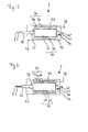
- the pump head 4comprises a discharge element. This can be used as Abströmtran 27, as in Fig. 3 (a) is shown, or as a discharge hose 27 ', as in Fig. 3 (b) is shown executed.
- the in Fig. 3 (a) illustrated Abströmtress 27is fixed in the liquid-tight region 20 of the housing 5 on the housing 5.
- the Abströmnes 27has the shape of a jacket of a truncated cone and extends in the conveying direction 26, that this is widened in the conveying direction 26.
- the discharge element 27surrounds the delivery element 6 and the outlet region 24. It can also be provided in another embodiment that the outlet region 24 is partially surrounded by the Abströmtran 27.
- the pump head 4 in Fig. 3 (b)is different from the one in Fig. 3 (a) shown pump head 4 only in that instead of the Abströmles 27 a discharge hose 27 'is provided.
- Thisis attached to the housing 5 in the liquid-tight region 20 and extends from there in the conveying direction 26.
- the outflow hose 27 'is made of polyurethane and has openings 28, 28', 28 "in a region located in the conveying direction 26.
- the outlet tube 27 'is flexible and closes itself automatically when blood flow occurs opposite to the conveying direction 26, in that the outlet tube 27' is attached to the catheter 2 and / or to the catheter Housing 5 is pressed.
- Fig. 4 12schematically shows the diamond lattice 19 of the housing 5.
- the liquid-tight region 20 with the elastic covering 21 and the inlet region 22 and the outlet region 24are shown. Regions of the inlet region 22 and the outlet region 24 have a conical shape, while the liquid-tight region 20 in FIG Is substantially tubular.
- the grid 19has lattice struts, one of which is identified by the reference numeral 45 by way of example.
- the lattice struts 45extend in such a way that the substantially diamond-shaped lattice openings are larger both in the inlet region 22 and in the outlet region 24 than in the liquid-tight region 20.
- lattice strutsare arranged on a side of the housing 5 facing away from the observer Fig. 4 indicated only dotted.
- the lattice struts 45form a comparatively close-meshed lattice 19.
- the grating 19thirty-two struts or, if the circumference is considered at an axial position of the housing 5 with nodes, sixteen nodes.
- the number of lattice struts 45is halved along a circumference of the housing 5 by a pairing of the lattice struts, so that the housing 5 in the corresponding regions has sixteen lattice struts 45 along the circumference in which there are no nodes. Subsequently, the number of lattice struts 45 in the direction of the inlet region 22 and the outlet region 24 is reduced again by the pairing of the lattice struts 45, so that the housing 5 has eight lattice struts 45 in these regions.
- a grid 19 with larger grid openings than in the liquid-tight area 20is formed in the inlet area 22 and in the outlet area 24.
- the grid struts 45form a helical structure in the conical regions of the outlet region 24 and the inlet region 22, which leads to a reliable deployment of the pump head 4 when the pump head 4 is pushed out of a cannula.
- Fig. 5shows a schematic view of the motor 7.
- the motor 7is connected in the region of a stub shaft 29 with the catheter 2, which is glued into the stub shaft 29.
- the flexible drive shaft 3is guided.
- the motor 7also has a rotor 30 which comprises a rotor magnet 31.
- the flexible drive shaft 3is connected to the rotor 30 such that a Torque is transmitted in a rotation of the rotor 30 from the rotor 30 to the flexible drive shaft 3. Via the flexible drive shaft, the torque is transmitted to the conveying element 6, so that the pump assembly 1 is driven by the motor 7.
- the rotor 30is axially supported by two bearings 32, 33.
- One of these bearings 33is biased by a spring element 34 for axial stabilization of the rotor 30.
- the spring element 34may be embodied, for example, as a helical spring or as an annular spring.
- the bearings 32, 33may each be designed as a ball bearing or as a sliding bearing. If the bearings 32, 33 are designed as ball bearings, the bearings 32, 33 comprise ceramic balls and cages made of plastic, so that the ball bearings have non-magnetizable material.
- the rings of the bearingscan be made for example of a magnetizable metal or a non-magnetizable material.
- the bearings 32, 33are designed as plain bearings, they each include sliding partners made of DLC-coated implant steel and yttrium-stabilized zirconium oxide.
- the rotor magnet 31has a biocompatible DLC coating 35.
- the motor 7has a stator 36.
- the stator 36includes a plurality of windings 37, which are electrically conductively connected to power terminals 38.
- the stator 36has return plates 39.
- the windings 37are potted with a biocompatible epoxy resin containing thermally conductive alumina.
- a gap 40is formed with an annular cross-section.
- the gap 40has a width of 0.2 mm.
- This gap 40is in fluid communication with a flushing port 41 which is connected to a flushing port 42, wherein the flushing port 42 is disposed at a proximal end of the motor 7.
- the gap 40is in fluid communication with a gap formed between the drive shaft 3 and the catheter 2.
- a glucose solutionmay be flushed via the purge port 42 through the purge port 41 and the gap 40 and the clearance.
- the rotor 30is lapped during operation of the glucose solution.
- a radial distance between an outer side of the rotor magnet 31 and an inner side of the windings 37is 0.5 mm.
- An inner radius of the windings 37corresponds to 1.1 times an outer radius of the rotor magnet 31.
- the stator 36 and the rotor 30are non-detachably connected together for a user and enclosed in a motor housing 43.
- the motor housing 43may be connected, for example, with a handle or a heat sink. Due to the small distance between the windings 37 and the rotor magnet 31, the motor can be operated very efficiently, so that both the motor housing 43 and a possibly connected thereto handle or heat sink is heated at its touchable surfaces to less than 40 ° C, if the pump assembly 1 is operated at a speed of 32,000 revolutions per minute and a capacity of 2.5 liters per minute.
- the width of the gap 40is 0.15 mm.
- the sleeve 44comprises polyetheretherketone and is magnetically inactive.
- the sleeve 44is arranged such that, for example, the windings 37 and other parts of the stator 36 are separated by the sleeve 44 from the optionally flowing through the gap 40 rinsing liquid.
- An extension of the sleeve 44 in the axial directionis approximately 1.2 times an axial extent of the rotor magnet 31.
Landscapes
- Health & Medical Sciences (AREA)
- Heart & Thoracic Surgery (AREA)
- Engineering & Computer Science (AREA)
- Cardiology (AREA)
- General Health & Medical Sciences (AREA)
- Public Health (AREA)
- Biomedical Technology (AREA)
- Hematology (AREA)
- Life Sciences & Earth Sciences (AREA)
- Animal Behavior & Ethology (AREA)
- Mechanical Engineering (AREA)
- Anesthesiology (AREA)
- Veterinary Medicine (AREA)
- Vascular Medicine (AREA)
- Transplantation (AREA)
- External Artificial Organs (AREA)
- Structures Of Non-Positive Displacement Pumps (AREA)
- Permanent Magnet Type Synchronous Machine (AREA)
- Permanent Field Magnets Of Synchronous Machinery (AREA)
- Connection Of Motors, Electrical Generators, Mechanical Devices, And The Like (AREA)
Abstract
Translated fromGermanDescription
Translated fromGermanDie Anmeldung betrifft eine Blutpumpe gemäß dem Oberbegriff des Anspruchs 1. Insbesondere betrifft die Anmeldung eine Blutpumpe mit einem Motor.The application relates to a blood pump according to the preamble of claim 1. In particular, the application relates to a blood pump with a motor.
Aus dem Stand der Technik sind Blutpumpen mit einem proximalen und einem distalen Ende sowie einem dazwischen angeordneten Katheter bekannt, bei denen eine flexible Antriebswelle in einem Innenraum des Katheters geführt wird. Solche Blutpumpen weisen an ihrem distalen Ende typischerweise einen Pumpenkopf auf, der ein faltbares Gehäuse und ein faltbares Förderelement umfasst, wobei das Förderelement mit einem distalen Bereich der Antriebswelle verbunden ist. Derartige Pumpenköpfe können an schwer zugängliche Orte geführt werden. Beispielsweise kann ein solcher Pumpenkopf durch die Femoralarterie über den Aortenbogen in einen Bereich der Aortenklappe eines Patienten eingeschoben werden, um dort Blut vom linken Ventrikel des Herzens in die Aorta zu befördern. Angetrieben wird die Antriebswelle am proximalen Ende der Blutpumpe durch einen Motor, welcher sich typischerweise außerhalb des Körpers des Patienten befindet. Eine derartige Blutpumpe ist beispielsweise in der Druckschrift
Die Druckschrift
Ein Nachteil einer solchen Motoranordnung ist, dass diese vergleichsweise großvolumig ist, was insbesondere bei einer Befestigung der Motoranordnung an einem Bein eines Patienten Probleme verursachen kann. Darüber hinaus kann eine derartige Motoranordnung im Betrieb zu einer beträchtlichen ungewünschten Wärmeentwicklung führen. Ein weiterer Nachteil ist, dass es bei einer Montage des Systems zu erheblichen Verschmutzungen des Stators kommen kann, beispielsweise durch Unreinheiten an Handschuhen eines Anwenders, was gegebenenfalls eine aufwendige Reinigung und Sterilisation des wiederverwendbaren Stators erfordert.A disadvantage of such a motor arrangement is that it is comparatively large-volume, which can cause problems in particular when the motor arrangement is fastened to a leg of a patient. Moreover, such an engine assembly may result in significant undesirable heat buildup during operation. Another disadvantage is that it can lead to significant contamination of the stator when mounting the system, for example, by impurities on the gloves of a user, which may require a complicated cleaning and sterilization of the reusable stator.
Der vorliegenden Anmeldung liegt die Aufgabe zugrunde, eine Blutpumpe vorzuschlagen, die einfach in der Handhabung ist und die die oben genannten Nachteile bekannter Vorrichtungen überwindet.The present application has for its object to propose a blood pump, which is easy to handle and overcomes the above-mentioned disadvantages of known devices.
Diese Aufgabe wird gelöst durch eine Blutpumpe mit den Merkmalen des Hauptanspruchs. Vorteilhafte Weiterbildungen ergeben sich mit den Merkmalen der abhängigen Ansprüche und der Ausführungsbeispiele.This object is achieved by a blood pump with the features of the main claim. Advantageous developments emerge with the features of the dependent claims and the embodiments.
Die vorgeschlagene Blutpumpe umfasst eine in einem Katheter geführte und flexible Antriebswelle, ein in einem distalen Bereich der Antriebswelle mit der Antriebswelle verbundenes Förderelement und einen Motor, wobei der Motor einen Stator und einen in dem Stator drehbar gelagerten Rotor umfasst. Der Stator umfasst eine Wicklung und der Rotor einen Rotormagneten. Außerdem ist die Antriebswelle an einem proximalen Ende der Antriebswelle mit dem Rotor verbunden. Der Stator und der Rotor sind unlösbar miteinander verbunden und bilden einen Spalt aus, der durch den Rotor und den Stator begrenzt wird.The proposed blood pump comprises a flexible drive shaft guided in a catheter, a delivery element connected to the drive shaft in a distal region of the drive shaft, and a motor, the motor comprising a stator and a rotor rotatably mounted in the stator. The stator comprises a winding and the rotor comprises a rotor magnet. In addition, the drive shaft at a proximal end of the drive shaft with connected to the rotor. The stator and the rotor are permanently connected to each other and form a gap that is bounded by the rotor and the stator.
Insbesondere gegenüber den aus dem Stand der Technik bekannten modularen Bauweisen von Motoren für Blutpumpen, bei denen der Rotor und der Stator für einen Anwender lösbar ausgeführt sind, erlaubt die vorgeschlagene Blutpumpe eine kompakte Bauweise. Bei dieser bilden der Stator und der Rotor eine Einheit, die beispielsweise kraft- oder stoffschlüssig miteinander verbunden sein kann. Durch die kompakte Bauweise kann ein geringes Gewicht des Motors erreicht werden, wodurch ein gegebenenfalls an einem Patientenbein befestigter Motor eine geringere Last darstellt.In particular, compared to the known from the prior art modular design of motors for blood pumps, in which the rotor and the stator are designed to be releasable for a user, the proposed blood pump allows a compact design. In this case, the stator and the rotor form a unit which can be connected to one another, for example, by a force or material fit. Due to the compact design, a low weight of the engine can be achieved, whereby an optionally attached to a patient leg motor is a lower load.
Die Wicklung kann einen Innenradius aufweisen, der maximal einem 1,5-fachen, bevorzugt maximal einem 1,25-fachen, besonders bevorzugt maximal einem 1,15-fachen, eines Außenradius des Rotormagneten entspricht. Durch den Abstand zwischen der Wicklung und dem Rotormagneten ist der magnetische Luftspalt gegeben. Ein geringer Abstand zwischen Rotormagnet und Wicklung erlaubt eine effiziente Umwandlung von elektrischer Leistung in Pumpleistung, so dass Wärmeverluste im Motor beim Betrieb mit einer gewünschten Pumpleistung gering gehalten werden können. Da bei dem vorgeschlagenen Motor durch die einteilige Bauweise keine Gehäuseteile in dem magnetischen Luftspalt vorgesehen sein müssen, kann ein geringer Abstand zwischen der Wicklung und dem Rotormagneten im Vergleich zu Bauformen erreicht werden, bei denen der Stator und der Rotor einzeln gehäust ausgeführt sind. Bei einem Innenradius der Wicklung von 6 mm kann der Außenradius des Rotormagneten beispielsweise mehr als 5,25 mm betragen.The winding may have an inner radius that corresponds to a maximum of 1.5 times, preferably a maximum of 1.25 times, more preferably a maximum of 1.15 times, an outer radius of the rotor magnet. Due to the distance between the winding and the rotor magnet of the magnetic air gap is given. A small distance between rotor magnet and winding allows efficient conversion of electrical power into pump power so that heat losses in the motor can be kept low when operating at a desired pump power. Since no housing parts in the magnetic air gap must be provided in the proposed engine by the one-piece design, a small distance between the winding and the rotor magnet can be achieved compared to designs in which the stator and the rotor are designed individually housed. For example, with an inside radius of the coil of 6 mm, the outside radius of the rotor magnet may be more than 5.25 mm.
Beispielsweise kann ein radialer Abstand zwischen der Wicklung und dem Rotormagneten maximal 2 mm, vorzugsweise maximal 1,25 mm, besonders vorzugsweise maximal 0,75 mm, betragen.For example, a radial distance between the winding and the rotor magnet is a maximum of 2 mm, preferably a maximum of 1.25 mm, particularly preferably a maximum of 0.75 mm.
Der Spalt weist typischerweise einen ringförmigem Querschnitt auf. Der Spalt weist eine Breite auf, die einer Breite des magnetischen Luftspalts entspricht oder die geringer ist als die Breite des magnetischen Luftspalts. Es kann vorgesehen sein, dass der Spalt eine Breite von maximal 1 mm, vorzugsweise maximal 0,5 mm, besonders vorzugsweise maximal 0,25 mm, aufweist.The gap typically has an annular cross-section. The gap has a width that corresponds to a width of the magnetic air gap or that is smaller than the width of the magnetic air gap. It can be provided that the gap has a maximum width of 1 mm, preferably a maximum 0.5 mm, more preferably at most 0.25 mm.
Außerdem kann eine Spülöffnung vorgesehen sein, die in fluider Verbindung mit dem Spalt steht. Die Spülöffnung kann in fluider Verbindung mit einem Spülanschluss stehen. Ein solcher Spülanschluss kann beispielsweise an einem proximalen Ende des Motors angeordnet sein.In addition, a flushing opening may be provided, which is in fluid communication with the gap. The flushing port may be in fluid communication with a flushing port. Such a flushing connection can be arranged, for example, at a proximal end of the engine.
Darüber hinaus kann es vorgesehen sein, dass der Spalt in fluider Verbindung mit einem zwischen dem Katheter und der Antriebswelle ausgebildeten Zwischenraum steht. Auf diese Weise kann durch den Spülanschluss eine Spülflüssigkeit durch den Spalt in den Zwischenraum zwischen der Antriebswelle und dem Katheter gespült werden. Dadurch kann ein Schmieren der Antriebswelle in dem Katheter erreicht werden. Darüber hinaus kann durch ein Einleiten der Spülflüssigkeit durch den Spülanschluss verhindert werden, dass Blut eines Patienten in den Motor und insbesondere in den Spalt gelangt. Es kann auch eine Spülflüssigkeit durch den Spülanschluss, den Spalt und den Zwischenraum zwischen dem Katheter und der Antriebswelle in den Körper des Patienten geleitet werden. Als Spülflüssigkeit kann beispielsweise eine Glukoselösung verwendet werden.In addition, it can be provided that the gap is in fluid communication with a gap formed between the catheter and the drive shaft. In this way, a flushing fluid can be flushed through the gap into the gap between the drive shaft and the catheter through the flushing port. As a result, lubrication of the drive shaft in the catheter can be achieved. In addition, by introducing the rinsing liquid through the rinsing connection, blood from a patient can be prevented from entering the motor and, in particular, the gap. Also, irrigation fluid may be directed into the body of the patient through the irrigation port, the gap, and the clearance between the catheter and the drive shaft. As a rinsing liquid, for example, a glucose solution can be used.
Es kann vorgesehen sein, dass der Rotor von einem proximalen Ende zu einem distalen Ende von der Spülflüssigkeit umspült wird. Es kann auch vorgesehen sein, dass der Rotor von seinem distalen zu seinem proximalen Ende von der Spülflüssigkeit umspült wird.It can be provided that the rotor is flushed from a proximal end to a distal end of the rinsing liquid. It can also be provided that the rotor is flushed from its distal to its proximal end by the rinsing liquid.
Es können auch Kathether mit mehreren Lumen Verwendung finden, so dass eine Hin- und eine Rückspülung erreicht werden kann, wie es beispielsweise in der Druckschrift
Es kann vorgesehen sein, dass der Spalt eine minimale Breite von 0,05 mm aufweist, um einen zuverlässigen Durchfluss der Spülflüssigkeit durch den Spalt zu gewährleisten.It can be provided that the gap has a minimum width of 0.05 mm in order to ensure a reliable flow of the rinsing liquid through the gap.
Es kann vorgesehen sein, dass die Wicklung in eine Vergussmasse eingegossen ist. Ein Vergießen der Wicklung mit einer Vergussmasse ist geeignet, gegebenenfalls vorhandene Vertiefungen an einer Oberfläche der Wicklung zu verschließen und zu nivellieren. Die Vergussmasse kann ein dünnviskoses Material umfassen, welches geeignet ist, in die Vertiefungen hineinzufließen und diese auszufüllen.It can be provided that the winding is cast in a potting compound. A casting of the winding with a potting compound is suitable, if necessary to close existing existing wells on a surface of the winding and to level. The potting compound may comprise a thin viscous material which is suitable to flow into the recesses and to fill them.
Es kann vorgesehen sein, dass die Vergussmasse einen den Spalt begrenzenden Teil des Stators bildet. Durch die Vergussmasse kann eine weitgehend glatte Begrenzungsfläche des Spalts erreicht werden. Die Vergussmasse kann beispielsweise Epoxidharz umfassen. Darüber hinaus kann vorgesehen sein, dass die Vergussmasse beispielsweise Aluminiumoxid, Eisenpulver oder andere wärmeleitende Substanzen für eine verbesserte Wärmeübertragung aufweist. Zusätzlich kann durch die Vergussmasse erreicht werden, dass nach einem Entlüften des Spaltes eine verminderte Anzahl von Luftbläschen an dem Stator anhaftet.It can be provided that the potting compound forms a gap limiting part of the stator. By casting compound, a largely smooth boundary surface of the gap can be achieved. The potting compound may comprise, for example, epoxy resin. In addition, it can be provided that the potting compound, for example, alumina, iron powder or other heat-conducting substances for improved heat transfer. In addition, can be achieved by the potting compound that after venting the gap a reduced number of air bubbles adhering to the stator.
Durch die Vergussmasse kann eine Beschädigung oder Korrosion der Wicklung durch eine Spülflüssigkeit oder gegebenenfalls durch die Spülflüssigkeit transportierte Partikel verhindert werden. Darüber hinaus kann durch die Vergussmasse verhindert werden, dass sich die Partikel an der Wicklung absetzen.By the potting compound damage or corrosion of the winding by a rinsing liquid or optionally transported by the rinsing liquid particles can be prevented. In addition, can be prevented by the potting compound that settle the particles on the winding.
Außerdem kann es vorgesehen sein, dass die Vergussmasse biokompatibles Material aufweist. Typischerweise ist die Vergussmasse hierbei vollständig aus biokompatiblem Material gefertigt, damit keine toxischen Substanzen über den Spülanschluss an den Patienten abgegeben werden. Es kann beispielsweise auch vorgesehen sein, dass die Wicklung mit Parylene beschichtet ist.In addition, it can be provided that the potting compound has biocompatible material. Typically, the potting compound is made entirely of biocompatible material, so that no toxic substances are delivered to the patient via the purging connection. It can also be provided, for example, that the winding is coated with parylene.
Es kann auch vorgesehen sein, dass der Stator eine fluiddichte Hülse mit im Wesentlichen ringförmigem Querschnitt aufweist, durch die der Spalt begrenzt wird. Durch die Hülse kann beispielsweise die Wicklung des Stators von der Spülflüssigkeit getrennt werden. Dadurch kann eine Beschädigung der Wicklung durch die Spülflüssigkeit verhindert werden. Es kann vorgesehen sein, dass die Hülse einen den Spalt begrenzenden Teil des Stators bildet.It can also be provided that the stator has a fluid-tight sleeve with a substantially annular cross-section, through which the gap is delimited. Through the sleeve, for example, the winding of the stator can be separated from the rinsing liquid. As a result, damage to the winding can be prevented by the rinsing liquid. It can be provided that the sleeve forms a gap limiting part of the stator.
Die Hülse kann auch derart ausgeführt sein, dass zusätzlich zur Wicklung auch andere Motorteile durch die Hülse von der Spülflüssigkeit getrennt und somit vor einer Beschädigung bewahrt werden. Beispielsweise können gegebenenfalls im Motor befindliche Lötstellen durch die Hülse vor einer Korrosion geschützt werden.The sleeve can also be designed such that in addition to the winding, other motor parts separated by the sleeve of the rinsing liquid and thus from being damaged. For example, possibly located in the engine solder joints are protected by the sleeve from corrosion.
Die Hülse kann beispielsweise einen Kunststoff, insbesondere Polyetheretherketon oder Polyethylen, oder Glas umfassen. Es kann auch vorgesehen sein, dass die Hülse aus einem elastischen Kunststoff, der beispielsweise Polyethylen umfasst, ausgebildet ist. Die Hülse dient einem Führen der Spülflüssigkeit und dient nicht notwendigerweise einer mechanischen Stabilisierung des Motors. Daher ist es möglich, dass die Hülse dünnwandig und/oder aus einem biegbaren Material gefertigt ist. Darüber hinaus wird eine äußere Form des Motors oder eines Teils des Motors nicht durch die Form der Hülse bestimmt. Daher kann es vorteilhaft sein, dass die Hülse die Wicklung und/oder den Rotor in axialer Richtung nur geringfügig überdeckt. Es kann beispielsweise vorgesehen sein, dass die Hülse eine Ausdehnung in axialer Richtung aufweist, die geringer als das 1,5-fache einer axialen Ausdehnung des Rotormagneten ist.The sleeve may comprise, for example, a plastic, in particular polyetheretherketone or polyethylene, or glass. It can also be provided that the sleeve is made of an elastic plastic, which comprises for example polyethylene. The sleeve serves to guide the rinsing liquid and does not necessarily serve to mechanically stabilize the motor. Therefore, it is possible that the sleeve is thin-walled and / or made of a bendable material. Moreover, an external shape of the motor or a part of the motor is not determined by the shape of the sleeve. Therefore, it may be advantageous for the sleeve to cover the winding and / or the rotor only slightly in the axial direction. It can be provided, for example, that the sleeve has an extension in the axial direction, which is less than 1.5 times an axial extent of the rotor magnet.
Es kann vorgesehen sein, dass der Rotor durch mindestens ein Gleitlager radial gelagert ist. Beispielsweise kann der Rotor durch zwei Gleitlager gelagert sein. Das mindestens eine Gleitlager kann beispielsweise nichtmagnetisierbare Materialien und/oder keramische Materialien, insbesondere Aluminiumoxid, Zirconiumoxid, Yttrium-stabilisiertes Zirconiumoxid oder Siliciumnitrid, umfassen. Darüber hinaus kann das Gleitlager beispielsweise Stahl, insbesondere Implantatstahl, umfassen. Es kann beispielsweise auch eine biokompatible Beschichtung mit diamantähnlichem amorphem Kohlenstoff vorgesehen sein.It can be provided that the rotor is radially supported by at least one sliding bearing. For example, the rotor may be supported by two plain bearings. The at least one sliding bearing may comprise, for example, non-magnetizable materials and / or ceramic materials, in particular aluminum oxide, zirconium oxide, yttrium-stabilized zirconium oxide or silicon nitride. In addition, the slide bearing may comprise, for example, steel, in particular implant steel. For example, a biocompatible coating with diamond-like amorphous carbon may also be provided.
Außerdem kann der Rotor durch mindestens ein Kugellager radial gelagert sein. Es kann vorgesehen sein, dass das mindestens eine Kugellager nichtmagnetisierbares Material umfasst. Insbesondere kann es vorgesehen sein, dass Teile des Kugellagers, an denen durch einen Betrieb des Motors ein Abrieb auftritt, nichtmagnetisierbares Material umfassen oder aus nichtmagnetisierbarem Material gefertigt sind. Dadurch wird erreicht, dass abgeriebenes Material der Teile des Kugellagers nicht an ferromagnetischen Komponenten des Motors anhaftet. Beispielsweise kann verhindert werden, dass ferromagnetischer Abrieb an dem Rotor haften bleibt und dadurch zu Beschädigungen des Rotors führt. Des Weiteren kann verhindert werden, dass ferromagnetischer Abrieb die Wicklung oder andere Komponenten des Motors beschädigt.In addition, the rotor can be supported radially by at least one ball bearing. It can be provided that the at least one ball bearing comprises non-magnetizable material. In particular, it may be provided that parts of the ball bearing, on which an abrasion occurs by operation of the motor, comprise non-magnetizable material or are made of non-magnetizable material. This ensures that abraded material of the parts of the ball bearing does not adhere to ferromagnetic components of the motor. For example, it can be prevented that ferromagnetic Abrasion adheres to the rotor and thereby leads to damage to the rotor. Furthermore, ferromagnetic abrasion can be prevented from damaging the winding or other components of the motor.
Beispielsweise kann das mindestens eine Kugellager Kugeln aufweisen, die ein keramisches Material umfassen. Außerdem kann das mindestens eine Kugellager einen Käfig aufweisen, der einen Kunststoff umfasst. Beispielsweise kann der Käfig Polyethylen oder Polytetrafluorethylen umfassen. Die Kugeln können auch vollständig aus einem keramischen Material bestehen. Der Käfig kann vollständig aus einem Kunststoff ausgebildet sein.For example, the at least one ball bearing may comprise balls which comprise a ceramic material. In addition, the at least one ball bearing may have a cage comprising a plastic. For example, the cage may comprise polyethylene or polytetrafluoroethylene. The balls can also be made entirely of a ceramic material. The cage can be formed entirely from a plastic.
Typischerweise weist der Rotor eine Beschichtung und/oder eine Abdeckung zum Schutz des Rotormagneten auf. Es kann sein, dass die Beschichtung und/oder die Abdeckung einen den Spalt begrenzenden Teil des Rotors ausbildet. Sowohl die Beschichtung als auch die Abdeckung können biokompatibles Material umfassen oder aus biokompatiblem Material bestehen. Beispielsweise kann eine Beschichtung mit Parylene oder einem biokompatiblen Epoxidharz vorgesehen sein. Es kann auch eine Beschichtung aus diamantähnlichem amorphem Kohlenstoff vorgesehen sein. Die Beschichtung kann eine Dicke aufweisen, die geringer als 100 µm, vorzugsweise geringer als 10 µm, ist. Der Rotor kann beispielsweise eine Abdeckung aus Polyetheretherketon oder Edelstahl aufweisen.Typically, the rotor has a coating and / or a cover for protecting the rotor magnet. It may be that the coating and / or the cover forms a gap limiting part of the rotor. Both the coating and the cover may comprise biocompatible material or be made of biocompatible material. For example, a coating with parylene or a biocompatible epoxy resin may be provided. It may also be provided a coating of diamond-like amorphous carbon. The coating may have a thickness which is less than 100 μm, preferably less than 10 μm. The rotor may for example have a cover of polyetheretherketone or stainless steel.
Die Blutpumpe kann einen entfaltbaren Pumpenkopf aufweisen, der das Förderelement und ein Gehäuse umfasst, wobei das Förderelement und das Gehäuse derart ausgebildet sind, dass diese sich nach einer aufgezwungenen Kompression selbstständig entfalten. Ein entfaltbarer Pumpenkopf erlaubt eine relativ große Ausführung des Pumpenkopfs und der Förderelemente bei relativ kleinem Durchmesser einer für das Einführen der Blutpumpe vorgesehenen Öffnung im Gewebe eines Patienten.The blood pump may include a deployable pumphead that includes the delivery member and a housing, wherein the delivery member and the housing are configured to self-deploy after forced compression. A deployable pump head allows a relatively large design of the pump head and the conveying elements at a relatively small diameter of an opening provided for the introduction of the blood pump opening in the tissue of a patient.
Typischerweise ist die Pumpe eingerichtet zum Pumpen von Blut von einem Ventrikel in ein Blutgefäß eines Patienten, wenn der Motor außerhalb eines Körpers des Patienten angeordnet ist. Der Motor kann beispielsweise für ein Befestigen an einem Oberschenkel des Patienten eingerichtet sein.Typically, the pump is arranged to pump blood from a ventricle into a blood vessel of a patient when the motor is located outside of a patient's body. For example, the motor may be configured for attachment to a thigh of the patient.
Dafür weist die flexible Antriebswelle eine ausreichende Länge auf, die von der Anatomie des Patienten abhängig ist. Typischerweise weist die flexible Welle hierbei eine Länge von mindestens 50 cm, vorzugsweise mindestens 90 cm, auf. Eine maximale Länge der flexiblen Antriebswelle beträgt 200 cm, vorzugsweise 150 cm.For the flexible drive shaft has a sufficient length, which is dependent on the anatomy of the patient. Typically, the flexible shaft has a length of at least 50 cm, preferably at least 90 cm. A maximum length of the flexible drive shaft is 200 cm, preferably 150 cm.
Bei einer Verwendung einer Blutpumpe, die durch einen Motor angetrieben wird, der sich außerhalb eines Patienten befindet, müssen gegebenenfalls im Vergleich zu Blutpumpen, die durch einen Motor im Patientenkörper angetrieben werden, höhere Anforderungen an die Effizienz des Motors erfüllt werden. Beispielsweise ist für einen Motor, der innerhalb des Patientenkörpers angeordnet ist, der Abtransport von im Betrieb erzeugter Wärme über das Blutsystem des Patienten von Vorteil. Eine von einer außerhalb des Patientenkörpers erzeugte Wärme benötigt hingegen unter Umständen weitere Elemente zur Wärmeabfuhr oder eine besonders effiziente Betriebsweise.When using a blood pump driven by a motor external to a patient, higher demands on the efficiency of the motor may need to be met as compared to blood pumps driven by a motor in the patient's body. For example, for a motor located within the patient's body, the removal of heat generated during operation via the patient's blood system is beneficial. On the other hand, a heat generated outside of the patient's body may require additional elements for heat dissipation or a particularly efficient mode of operation.
Die Anmeldung betrifft ferner ein Betriebsverfahren für die vorgeschlagene Blutpumpe. Hierbei erwärmt sich eine berührbare Oberfläche eines Gehäuses des Motors während eines Permanentbetriebs bei einer Drehzahl von 15.000, bevorzugt mindestens 30.000, Umdrehungen pro Minute auf eine Temperatur von nicht mehr als 60 °C, vorzugsweise von nicht mehr als 48 °C, besonders vorzugsweise von nicht mehr als 43 °C. insbesondere bei einer Befestigung des Motors an einem Oberschenkel eines Patienten ist es wichtig, dass sich das Gehäuse des Motors im Betrieb nicht zu stark erhitzt.The application further relates to an operating method for the proposed blood pump. In this case, a contactable surface of a housing of the motor heats up during a permanent operation at a speed of 15,000, preferably at least 30,000 revolutions per minute to a temperature of not more than 60 ° C, preferably not more than 48 ° C, more preferably not more than 43 ° C. In particular, when attaching the motor to a thigh of a patient, it is important that the housing of the motor does not overheat during operation.
Darüber hinaus kann ein Betriebsverfahren vorgesehen sein, bei dem sich berührbare Oberflächen des Gehäuses des Motors während eines Permanentbetriebs der Blutpumpe bei einer Förderleistung von mindestens 1 l/min, bevorzugt mindestens 2 l/min, auf eine Temperatur von nicht mehr als 60 °C, vorzugsweise von nicht mehr als 48 °C, besonders vorzugsweise von nicht mehr als 43 °C.In addition, an operating method may be provided in which touchable surfaces of the housing of the motor during a permanent operation of the blood pump at a flow rate of at least 1 l / min, preferably at least 2 l / min, to a temperature of not more than 60 ° C, preferably not more than 48 ° C, more preferably not more than 43 ° C.
Es kann vorgesehen sein, dass die Blutpumpe zum Abführen von im Betrieb verursachter Wärme einen Kühlkörper, beispielsweise mit Kühlrippen, die mit dem Motor wärmeleitend verbunden sind, oder ein Wärmerohr aufweist. Es kann auch vorgesehen sein, dass die Blutpumpe für eine Wärmeabgabe an ein Gewebe des Patienten, beispielsweise über die Haut des Oberschenkels, eingerichtet ist.It can be provided that the blood pump for dissipating heat generated during operation has a heat sink, for example, with cooling fins, which are thermally conductively connected to the engine, or a heat pipe. It can also be provided that the blood pump for a heat to a Tissue of the patient, for example, over the skin of the thigh, is set up.
Die Blutpumpe kann mit allen beschriebenen Komponenten steril verpackt geliefert werden. Die Blutpumpe kann beispielsweise mittels Gammasterilisation oder unter Verwendung von Ethylenoxid sterilisiert werden. Nach einem Gebrauch der Blutpumpe kann diese vollständig entsorgt werden. Somit entfällt bei der vorgeschlagenen Blutpumpe eine wiederholte Reinigung oder Sterilisation von Teilen der Blutpumpe, insbesondere des Motors, durch einen Anwender.The blood pump can be supplied sterile packed with all described components. For example, the blood pump may be sterilized by gamma sterilization or by using ethylene oxide. After use of the blood pump, it can be disposed of completely. Thus, in the proposed blood pump, repeated cleaning or sterilization of parts of the blood pump, especially the motor, by a user is eliminated.
Ausführungsbeispiele der Erfindung werden nachfolgend anhand der Abbildungen beschrieben. Es zeigen
- Fig. 1
- eine schematische Darstellung einer Pumpenanordnung,
- Fig. 2
- eine schematische Darstellung eines Pumpenkopfes,
- Fign. 3(a), (b)
- zwei weitere schematische Darstellungen des Pumpenkopfes,
- Fig. 4
- eine schematische Darstellung eines Gehäuses,
- Fig. 5
- eine schematische Darstellung eines Motors und
- Fig. 6
- eine schematische Darstellung eines weiteren Motors.
- Fig. 1
- a schematic representation of a pump assembly,
- Fig. 2
- a schematic representation of a pump head,
- FIGS. 3 (a), (b)
- two further schematic representations of the pump head,
- Fig. 4
- a schematic representation of a housing,
- Fig. 5
- a schematic representation of an engine and
- Fig. 6
- a schematic representation of another engine.
Die Pumpenanordnung 1 kann aber auch eingerichtet sein für ein Fördern von Blut in einer Richtung von dem proximalen Ende 14 zum distalen Ende 13 der Pumpenanordnung 1, was sich beispielsweise für eine Rechtsherz-Unterstützung eignet.However, the pump assembly 1 may also be configured to deliver blood in a direction from the
Der Pumpenkopf 4 ist in
Das Gehäuse 5 ist als Rautengitter 19 ausgeführt und weist in einem flüssigkeitsdichten Bereich 20 eine elastische Bespannung 21 aus Polyurethan auf. Die elastische Bespannung 21 bedeckt eine Innenseite und eine Außenseite des Rautengitters 19 derart, dass durch das Gitter 19 ausgebildete rautenförmige Gitteröffnungen in dem flüssigkeitsdichten Bereich 20 durch die elastische Bespannung 21 flüssigkeitsdicht verschlossen werden.The
Darüber hinaus weist das Gehäuse 5 einen Einlassbereich 22 auf, der nicht von der elastischen Bespannung 21 bedeckt wird. In dem Einlassbereich 22 bilden die rautenförmigen Gitteröffnungen Einlassöffnungen aus, von denen eine in
Bei einem Betrieb der Pumpenanordnung 1 wird die Antriebswelle 3 durch den Motor 7 angetrieben, so dass das mit der Antriebswelle 3 verbunden Förderelement 6 um eine Achse der Antriebswelle 3 rotiert. Dadurch wird Blut durch die Einlassöffnungen des Einlassbereichs 22 in das Gehäuse 5 befördert und tritt anschließend durch die Auslassöffnungen des Auslassbereichs 24 aus dem Gehäuse 5 aus. Auf diese Weise wird durch die Pumpenanordnung 1 Blut in einer Förderrichtung 26 gefördert.During operation of the pump arrangement 1, the
Die elastische Bespannung 21 umgibt eine axiale Ausdehnung des Förderelements 6 nicht vollständig. Das Förderelement 6 ragt stattdessen teilweise in den Auslassbereich 24 hinein, so dass zumindest die Auslassöffnung mit dem Bezugszeichen 25 seitlich, d.h. in radialer Richtung, neben dem Förderelement 6 angeordnet ist. Die elastische Bespannung 21 ist hingegen an ihrem distalen Ende derart ausgeführt, dass das Förderelement 6 nicht oder nicht wesentlich in den Einlassbereich 22 hineinragt und somit nicht seitlich von Einlassöffnungen umgeben ist.The
Die elastische Bespannung 21 und das Förderelement 6 sind so ausgestaltet und zueinander angeordnet, dass etwa ein Drittel der axialen Ausdehnung des Förderelements 6 nicht von der elastischen Bespannung 21, die den flüssigkeitsdichten Bereich 20 bildet, umgeben ist. Derselbe Anteil der axialen Ausdehnung des Förderelements 6 ist in dem gezeigten Beispiel von dem Auslassbereich 24 umgeben.The
Zusätzlich umfasst der Pumpenkopf 4 ein Abströmelement. Dieses kann als Abströmschirm 27, wie in
Der in
Der Pumpenkopf 4 in
Im flüssigkeitsdichten Bereich 20 bilden die Gitterstreben 45 ein vergleichsweise engmaschiges Gitter 19 aus. Entlang eines Umfangs des Gehäuses 5 im flüssigkeitsdichten Bereich 20 weist das Gitter 19 zweiunddreißig Streben beziehungsweise, sofern der Umfang an einer axialen Position des Gehäuses 5 mit Knotenpunkten betrachtet wird, sechzehn Knoten auf. Durch ein derart engmaschiges Gitter 19 wird ein weitgehend runder Querschnitt des Gehäuses 5 in dem flüssigkeitsdichten Bereich 20 erreicht.In the liquid-
Vom flüssigkeitsdichten Bereich 20 in Richtung des Einlassbereichs 22 und in Richtung des Auslassbereichs 24 wird die Anzahl der Gitterstreben 45 entlang eines Umfangs des Gehäuses 5 durch ein paarweises Zusammenführen der Gitterstreben halbiert, so dass das Gehäuse 5 in den entsprechenden Bereichen sechzehn Gitterstreben 45 entlang des Umfangs aufweist, in dem keine Knotenpunkte vorliegen. Anschließend wird die Anzahl der Gitterstreben 45 in Richtung des Einlassbereichs 22 und des Auslassbereichs 24 erneut durch das paarweise Zusammenführen der Gitterstreben 45 reduziert, so dass Gehäuse 5 in diesen Bereichen acht Gitterstreben 45 aufweist. Im Auslassbereich 24 erfolgt eine weitere Reduzierung der Anzahl der Gitterstreben 45 in der oben genannten Weise, so dass das Gehäuse 5 in einem weiter in Förderrichtung 26 gelegenen Bereich lediglich vier Gitterstreben 45 entlang eines Umfangs aufweist.From the liquid-
Durch die beschriebene Reduzierung der Anzahl der Gitterstreben 45 bildet sich in dem Einlassbereich 22 und in dem Auslassbereich 24 ein Gitter 19 mit größeren Gitteröffnungen als im flüssigkeitsdichten Bereich 20 aus.Due to the described reduction of the number of grid struts 45, a
Die Gitterstreben 45 bilden in den konischen Bereichen des Auslassbereichs 24 und des Einlassbereichs 22 eine spiralförmige Struktur, was bei einem Hinausschieben des Pumpenkopfes 4 aus einer Kanüle zu einem zu einem zuverlässigen Entfalten des Pumpenkopfs 4 führt.The grid struts 45 form a helical structure in the conical regions of the
Die flexible Antriebswelle 3 ist derart mit dem Rotor 30 verbunden, dass ein Drehmoment bei einer Rotation des Rotors 30 von dem Rotor 30 auf die flexible Antriebswelle 3 übertragen wird. Über die flexible Antriebswelle wird das Drehmoment auf das Förderelement 6 übertragen, so dass die Pumpenanordnung 1 durch den Motor 7 angetrieben wird.The
Der Rotor 30 ist axial durch zwei Lager 32, 33 gelagert. Eines dieser Lager 33 ist durch ein Federelement 34 vorgespannt für eine axiale Stabilisierung des Rotors 30. Das Federelement 34 kann beispielsweise als eine Schraubenfeder oder als eine Ringfeder ausgeführt sein. Die Lager 32, 33 können jeweils als Kugellager oder als Gleitlager ausgeführt sein. Wenn die Lager 32, 33 als Kugellager ausgeführt sind, umfassen die Lager 32, 33 Kugeln aus Keramik und Käfige aus Kunststoff, so dass die Kugellager nichtmagnetisierbares Material aufweisen. Die Ringe der Lager können beispielsweise aus einem magnetisierbaren Metall oder aus einem nichtmagnetisierbaren Material gefertigt sein. Wenn die Lager 32, 33 als Gleitlager ausgeführt sind, umfassen diese jeweils Gleitpartner aus DLC-beschichtetem Implantatstahl und Yttrium-stabilisiertem Zirconiumoxid.The
Der Rotormagnet 31 weist eine biokompatible DLC-Beschichtung 35 auf. Außerdem weist der Motor 7 einen Stator 36 auf. Der Stator 36 umfasst mehrere Wicklungen 37, die mit Stromanschlüssen 38 elektrisch leitfähig verbunden sind. Darüber hinaus weist der Stator 36 Rückschlussbleche 39 auf. Die Wicklungen 37 sind mit einem biokompatiblen Epoxidharz vergossen, welches wärmeleitendes Aluminiumoxid enthält.The
Zwischen einer Innenseite der Beschichtung der Wicklungen 37 und einer Außenseite der Beschichtung 35 des Rotormagneten 31 ist ein Spalt 40 mit ringförmigem Querschnitt ausgebildet. Der Spalt 40 weist eine Breite von 0,2 mm auf. Dieser Spalt 40 steht in fluider Verbindung mit einer Spülöffnung 41, die mit einem Spülanschluss 42 verbunden ist, wobei der Spülanschluss 42 an einem proximalen Ende des Motors 7 angeordnet ist. Darüber hinaus steht der Spalt 40 in fluider Verbindung mit einem zwischen der Antriebswelle 3 und dem Katheter 2 ausgebildeten Zwischenraum. Somit kann beispielsweise eine Glukoselösung über den Spülanschluss 42 durch die Spülöffnung 41 und den Spalt 40 und den Zwischenraum gespült werden. Auf diese Weise wird der Rotor 30 im Betrieb von der Glukoselösung umspült. Ein radialer Abstand zwischen einer Außenseite des Rotormagneten 31 und einer Innenseite der Wicklungen 37 beträgt 0,5 mm. Ein Innenradius der Wicklungen 37 entspricht hierbei dem 1,1-fachen eines Außenradius des Rotormagneten 31.Between an inner side of the coating of the
Der Stator 36 und der Rotor 30 sind für einen Anwender nicht lösbar miteinander verbunden und in ein Motorgehäuse 43 eingefasst. Das Motorgehäuse 43 kann beispielsweise mit einem Griff oder einem Kühlkörper verbunden sein. Durch den geringen Abstand zwischen den Wicklungen 37 und dem Rotormagneten 31 kann der Motor sehr effizient betrieben werden, so dass sowohl das Motorgehäuse 43 als auch ein gegebenenfalls mit diesem verbundener Griff oder Kühlkörper an seinen berührbaren Oberflächen auf weniger als 40 °C erwärmt wird, wenn die Pumpenanordnung 1 bei einer Drehzahl von 32.000 Umdrehungen pro Minute und einer Förderleistung von 2.5 l pro Minute betrieben wird.The
Der in
Lediglich in den Ausführungsbeispielen offenbarte Merkmale der verschiedenen Ausführungsformen können miteinander kombiniert und einzeln beansprucht werden.Only features disclosed in the embodiments of the various embodiments can be combined and claimed individually.
Claims (20)
Translated fromGermandadurch gekennzeichnet, dass
der Stator (36) und der Rotor (30) unlösbar miteinander verbunden sind und einen Spalt (40) ausbilden, der durch den Rotor (30) und den Stator (36) begrenzt wird.A blood pump comprising a flexible drive shaft (3) guided in a catheter (2), a conveying element (6) connected to the drive shaft (3) in a distal region of the drive shaft (3) and a motor (7), the motor ( 7) comprises a stator (36) and a rotor (30) rotatably mounted in the stator (36), wherein the stator (36) comprises a winding (37) and the rotor (30) comprises a rotor magnet (31), the drive shaft (3) is connected to the rotor (30) at a proximal end of the drive shaft (3),
characterized in that
the stator (36) and the rotor (30) are permanently connected to one another and form a gap (40) bounded by the rotor (30) and the stator (36).
Priority Applications (22)
| Application Number | Priority Date | Filing Date | Title |
|---|---|---|---|
| EP15189242.9AEP3153191A1 (en) | 2015-10-09 | 2015-10-09 | Blood pump |
| DK16775731.9TDK3359214T3 (en) | 2015-10-09 | 2016-10-04 | blood pump |
| JP2018517850AJP6847935B2 (en) | 2015-10-09 | 2016-10-04 | Blood pump |
| CN201680059064.6ACN108136090B (en) | 2015-10-09 | 2016-10-04 | Blood pump |
| EP19202306.7AEP3628344B1 (en) | 2015-10-09 | 2016-10-04 | Blood pump |
| US15/766,698US11219755B2 (en) | 2015-10-09 | 2016-10-04 | Blood pump |
| CN202110944594.1ACN113633886A (en) | 2015-10-09 | 2016-10-04 | Blood pump |
| PCT/EP2016/073697WO2017060254A1 (en) | 2015-10-09 | 2016-10-04 | Blood pump |
| HK18110869.7AHK1251499B (en) | 2015-10-09 | 2016-10-04 | Blood pump |
| EP16775731.9AEP3359214B1 (en) | 2015-10-09 | 2016-10-04 | Blood pump |
| KR1020237044407AKR20240005172A (en) | 2015-10-09 | 2016-10-04 | Blood pump |
| CA3000579ACA3000579A1 (en) | 2015-10-09 | 2016-10-04 | Blood pump |
| EP23219188.2AEP4316568A3 (en) | 2015-10-09 | 2016-10-04 | Blood pump |
| KR1020187012544AKR102618774B1 (en) | 2015-10-09 | 2016-10-04 | blood pump |
| ES19202306TES2976458T3 (en) | 2015-10-09 | 2016-10-04 | Blood pump |
| DK19202306.7TDK3628344T3 (en) | 2015-10-09 | 2016-10-04 | Blood pump |
| ES16775731TES2775181T3 (en) | 2015-10-09 | 2016-10-04 | Blood pump |
| JP2021033192AJP7206306B2 (en) | 2015-10-09 | 2021-03-03 | blood pump |
| US17/542,940US11826501B2 (en) | 2015-10-09 | 2021-12-06 | Blood pump |
| JP2023000190AJP7664295B2 (en) | 2015-10-09 | 2023-01-04 | Blood pump |
| US18/379,221US12290674B2 (en) | 2015-10-09 | 2023-10-12 | Blood pump |
| JP2025009433AJP2025061611A (en) | 2015-10-09 | 2025-01-22 | Blood pump |
Applications Claiming Priority (1)
| Application Number | Priority Date | Filing Date | Title |
|---|---|---|---|
| EP15189242.9AEP3153191A1 (en) | 2015-10-09 | 2015-10-09 | Blood pump |
Publications (1)
| Publication Number | Publication Date |
|---|---|
| EP3153191A1true EP3153191A1 (en) | 2017-04-12 |
Family
ID=54292710
Family Applications (4)
| Application Number | Title | Priority Date | Filing Date |
|---|---|---|---|
| EP15189242.9AWithdrawnEP3153191A1 (en) | 2015-10-09 | 2015-10-09 | Blood pump |
| EP19202306.7AActiveEP3628344B1 (en) | 2015-10-09 | 2016-10-04 | Blood pump |
| EP16775731.9AActiveEP3359214B1 (en) | 2015-10-09 | 2016-10-04 | Blood pump |
| EP23219188.2APendingEP4316568A3 (en) | 2015-10-09 | 2016-10-04 | Blood pump |
Family Applications After (3)
| Application Number | Title | Priority Date | Filing Date |
|---|---|---|---|
| EP19202306.7AActiveEP3628344B1 (en) | 2015-10-09 | 2016-10-04 | Blood pump |
| EP16775731.9AActiveEP3359214B1 (en) | 2015-10-09 | 2016-10-04 | Blood pump |
| EP23219188.2APendingEP4316568A3 (en) | 2015-10-09 | 2016-10-04 | Blood pump |
Country Status (9)
| Country | Link |
|---|---|
| US (3) | US11219755B2 (en) |
| EP (4) | EP3153191A1 (en) |
| JP (4) | JP6847935B2 (en) |
| KR (2) | KR102618774B1 (en) |
| CN (2) | CN108136090B (en) |
| CA (1) | CA3000579A1 (en) |
| DK (2) | DK3359214T3 (en) |
| ES (2) | ES2775181T3 (en) |
| WO (1) | WO2017060254A1 (en) |
Cited By (2)
| Publication number | Priority date | Publication date | Assignee | Title |
|---|---|---|---|---|
| CN110841123A (en)* | 2019-12-23 | 2020-02-28 | 张瑞娟 | Blood circulation device for cardiovascular treatment |
| CN111093730A (en)* | 2017-08-23 | 2020-05-01 | Ecp发展有限责任公司 | Drive shaft cover with heat conducting component |
Families Citing this family (60)
| Publication number | Priority date | Publication date | Assignee | Title |
|---|---|---|---|---|
| CN108742951B (en) | 2012-06-06 | 2021-05-25 | 洋红医疗有限公司 | Artificial kidney valve |
| EP4233702A3 (en) | 2013-03-13 | 2023-12-20 | Magenta Medical Ltd. | Manufacture of an impeller |
| US10583231B2 (en) | 2013-03-13 | 2020-03-10 | Magenta Medical Ltd. | Blood pump |
| US20150133861A1 (en) | 2013-11-11 | 2015-05-14 | Kevin P. McLennan | Thermal management system and method for medical devices |
| WO2016185473A1 (en) | 2015-05-18 | 2016-11-24 | Magenta Medical Ltd. | Blood pump |
| NZ737340A (en) | 2015-05-26 | 2019-06-28 | Icu Medical Inc | Disposable infusion fluid delivery device for programmable large volume drug delivery |
| EP3153191A1 (en)* | 2015-10-09 | 2017-04-12 | ECP Entwicklungsgesellschaft mbH | Blood pump |
| CA3039285A1 (en) | 2016-10-25 | 2018-05-03 | Magenta Medical Ltd. | Ventricular assist device |
| JP7094279B2 (en) | 2016-11-23 | 2022-07-01 | マジェンタ・メディカル・リミテッド | Blood pump |
| CA3066361A1 (en) | 2017-06-07 | 2018-12-13 | Shifamed Holdings, Llc | Intravascular fluid movement devices, systems, and methods of use |
| WO2019094963A1 (en) | 2017-11-13 | 2019-05-16 | Shifamed Holdings, Llc | Intravascular fluid movement devices, systems, and methods of use |
| EP3638336B1 (en)* | 2018-01-10 | 2022-04-06 | Magenta Medical Ltd. | Ventricular assist device |
| US10905808B2 (en) | 2018-01-10 | 2021-02-02 | Magenta Medical Ltd. | Drive cable for use with a blood pump |
| DE102018201030B4 (en) | 2018-01-24 | 2025-10-16 | Kardion Gmbh | Magnetic dome element with magnetic bearing function |
| CN112004563B (en) | 2018-02-01 | 2024-08-06 | 施菲姆德控股有限责任公司 | Intravascular blood pump and methods of use and manufacture |
| DE102018207611A1 (en) | 2018-05-16 | 2019-11-21 | Kardion Gmbh | Rotor bearing system |
| DE102018207575A1 (en) | 2018-05-16 | 2019-11-21 | Kardion Gmbh | Magnetic face turning coupling for the transmission of torques |
| US10722627B1 (en) | 2018-05-24 | 2020-07-28 | RBTS Inc. | Blood pump bearing with integrated fluid diffuser/inducer system |
| DE102018208541A1 (en) | 2018-05-30 | 2019-12-05 | Kardion Gmbh | Axial pump for a cardiac assist system and method of making an axial pump for a cardiac assist system |
| DE102018208555A1 (en) | 2018-05-30 | 2019-12-05 | Kardion Gmbh | Apparatus for anchoring a cardiac assist system in a blood vessel, method of operation, and method of making a device and cardiac assist system |
| DE102018208539A1 (en) | 2018-05-30 | 2019-12-05 | Kardion Gmbh | A motor housing module for sealing an engine compartment of a motor of a cardiac assist system and cardiac assistance system and method for mounting a cardiac assist system |
| DE102018208538A1 (en) | 2018-05-30 | 2019-12-05 | Kardion Gmbh | Intravascular blood pump and process for the production of electrical conductors |
| DE102018208550A1 (en) | 2018-05-30 | 2019-12-05 | Kardion Gmbh | A lead device for directing blood flow to a cardiac assist system, cardiac assist system, and method of making a lead device |
| US12343516B2 (en)* | 2018-06-12 | 2025-07-01 | Venstramedical Pty Limited | Intracardiac percutaneous pump for circulatory support and related systems and methods |
| DE102018210076A1 (en) | 2018-06-21 | 2019-12-24 | Kardion Gmbh | Method and device for detecting a state of wear of a cardiac support system, method and device for operating a cardiac support system and cardiac support system |
| DE102018210058A1 (en) | 2018-06-21 | 2019-12-24 | Kardion Gmbh | Stator blade device for guiding the flow of a fluid flowing out of an outlet opening of a heart support system, heart support system with stator blade device, method for operating a stator blade device and manufacturing method |
| DE102018211327A1 (en) | 2018-07-10 | 2020-01-16 | Kardion Gmbh | Impeller for an implantable vascular support system |
| DE102018212153A1 (en) | 2018-07-20 | 2020-01-23 | Kardion Gmbh | Inlet line for a pump unit of a cardiac support system, cardiac support system and method for producing an inlet line for a pump unit of a cardiac support system |
| US12161857B2 (en) | 2018-07-31 | 2024-12-10 | Shifamed Holdings, Llc | Intravascular blood pumps and methods of use |
| CN112654389A (en) | 2018-08-07 | 2021-04-13 | 开迪恩有限公司 | Bearing device for a cardiac support system and method for flushing an intermediate space in a bearing device for a cardiac support system |
| WO2020073047A1 (en) | 2018-10-05 | 2020-04-09 | Shifamed Holdings, Llc | Intravascular blood pumps and methods of use |
| CN111166948A (en)* | 2018-11-09 | 2020-05-19 | 上海微创医疗器械(集团)有限公司 | Percutaneous blood pump and basket thereof |
| AU2020211431B2 (en) | 2019-01-24 | 2024-10-24 | Magenta Medical Ltd | Ventricular assist device |
| EP3955985B1 (en) | 2019-04-19 | 2024-08-21 | Abiomed, Inc. | Cooled mechanical circulatory support system and method of operation |
| EP3972661B1 (en) | 2019-05-23 | 2024-09-11 | Magenta Medical Ltd. | Blood pumps |
| CN112107749B (en)* | 2019-06-21 | 2022-06-07 | 上海微创心力医疗科技有限公司 | Flow guiding device and catheter pump |
| WO2021011473A1 (en) | 2019-07-12 | 2021-01-21 | Shifamed Holdings, Llc | Intravascular blood pumps and methods of manufacture and use |
| US11654275B2 (en) | 2019-07-22 | 2023-05-23 | Shifamed Holdings, Llc | Intravascular blood pumps with struts and methods of use and manufacture |
| USD939079S1 (en) | 2019-08-22 | 2021-12-21 | Icu Medical, Inc. | Infusion pump |
| US12121713B2 (en) | 2019-09-25 | 2024-10-22 | Shifamed Holdings, Llc | Catheter blood pumps and collapsible blood conduits |
| EP4501393A3 (en) | 2019-09-25 | 2025-04-09 | Shifamed Holdings, LLC | Catheter blood pumps and collapsible pump housings |
| WO2021062265A1 (en) | 2019-09-25 | 2021-04-01 | Shifamed Holdings, Llc | Intravascular blood pump systems and methods of use and control thereof |
| EP4072650A4 (en) | 2019-12-11 | 2024-01-10 | Shifamed Holdings, LLC | Descending aorta and vena cava blood pumps |
| WO2021150354A1 (en) | 2020-01-21 | 2021-07-29 | Boston Scientific Scimed Inc | Magnetic drives having flux enhancers for blood pumps |
| DE102020102474A1 (en) | 2020-01-31 | 2021-08-05 | Kardion Gmbh | Pump for conveying a fluid and method for manufacturing a pump |
| EP3984589B1 (en) | 2020-04-07 | 2023-08-23 | Magenta Medical Ltd. | Magnetic phase sensing |
| CN112472999B (en)* | 2020-12-22 | 2025-03-21 | 深圳核心医疗科技股份有限公司 | Blood Pump |
| CN113457006B (en)* | 2021-06-30 | 2023-03-17 | 苏州心擎医疗技术有限公司 | Foldable impeller and blood pump |
| CN113244526B (en)* | 2021-07-06 | 2021-11-19 | 丰凯医疗器械(上海)有限公司 | Artificial auxiliary blood pumping device |
| WO2023283751A1 (en)* | 2021-07-12 | 2023-01-19 | 苏州心擎医疗技术有限公司 | Device for assisting heart in event of heart failure |
| WO2023062453A1 (en)* | 2021-10-11 | 2023-04-20 | Magenta Medical Ltd | Ventricular assist device |
| USD1052728S1 (en) | 2021-11-12 | 2024-11-26 | Icu Medical, Inc. | Medical fluid infusion pump |
| WO2023096892A1 (en) | 2021-11-23 | 2023-06-01 | Boston Scientific Scimed Inc. | Percutaneous circulatory support device facilitating reduced hemolysis |
| TW202335698A (en)* | 2022-01-28 | 2023-09-16 | 德商阿比奥梅德歐洲有限公司 | Blood pump |
| WO2023158870A2 (en)* | 2022-02-21 | 2023-08-24 | Abiomed, Inc. | Method of purging a blood pump |
| CN114704485B (en)* | 2022-03-28 | 2024-07-16 | 山西华鑫图科电机驱动有限公司 | Rare earth permanent magnet outer rotor motor for fan |
| WO2023230157A1 (en)* | 2022-05-24 | 2023-11-30 | Kardion Gmbh | Insertion catheter for a circulatory support catheter |
| CN115282467B (en)* | 2022-07-08 | 2024-02-23 | 深圳核心医疗科技股份有限公司 | Driving mechanism and blood pump |
| WO2025051679A1 (en)* | 2023-09-08 | 2025-03-13 | Abiomed Europe Gmbh | Pump section for a blood pump and blood pump |
| CN119345595B (en)* | 2024-12-25 | 2025-05-27 | 安徽通灵仿生科技有限公司 | A flushing system based on a ventricular catheter pump and a flushing pressure control method |
Citations (4)
| Publication number | Priority date | Publication date | Assignee | Title |
|---|---|---|---|---|
| US4895557A (en) | 1987-12-07 | 1990-01-23 | Nimbus Medical, Inc. | Drive mechanism for powering intravascular blood pumps |
| US5040944A (en)* | 1989-09-11 | 1991-08-20 | Cook Einar P | Pump having impeller rotational about convoluted stationary member |
| DE102013011042A1 (en)* | 2012-07-03 | 2014-01-09 | Thoratec Corporation | Motor assembly for catheter pump |
| EP2868331A2 (en) | 2013-11-01 | 2015-05-06 | ECP Entwicklungsgesellschaft mbH | Pump, in particular blood pump |
Family Cites Families (27)
| Publication number | Priority date | Publication date | Assignee | Title |
|---|---|---|---|---|
| GB802301A (en)* | 1956-10-05 | 1958-10-01 | Chempump Corp | Improvements in electric motor driven pumps |
| GB1508428A (en) | 1974-07-25 | 1978-04-26 | Sealed Motor Constr Co Ltd | Axial gap electric motors |
| US4625712A (en)* | 1983-09-28 | 1986-12-02 | Nimbus, Inc. | High-capacity intravascular blood pump utilizing percutaneous access |
| US5112200A (en)* | 1990-05-29 | 1992-05-12 | Nu-Tech Industries, Inc. | Hydrodynamically suspended rotor axial flow blood pump |
| US6302910B1 (en)* | 1992-06-23 | 2001-10-16 | Sun Medical Technology Research Corporation | Auxiliary artificial heart of an embedded type |
| JPH06102087B2 (en)* | 1992-12-15 | 1994-12-14 | 株式会社サンメディカル技術研究所 | Artificial heart |
| US5957672A (en)* | 1993-11-10 | 1999-09-28 | The United States Of America As Represented By The Administrator Of The National Aeronautics And Space Administration | Blood pump bearing system |
| US5527272A (en)* | 1994-02-14 | 1996-06-18 | Fresenius Usa, Inc. | Bacteriocidal dialysis collection bag and method |
| JPH08206192A (en)* | 1994-12-02 | 1996-08-13 | San Medical Gijutsu Kenkyusho:Kk | Seal mechanism for artificial heart |
| US5911685A (en)* | 1996-04-03 | 1999-06-15 | Guidant Corporation | Method and apparatus for cardiac blood flow assistance |
| US6048363A (en)* | 1997-05-13 | 2000-04-11 | Nagyszalanczy; Lorant | Centrifugal blood pump apparatus |
| DE29821564U1 (en)* | 1998-12-02 | 2000-07-13 | Impella Cardiotechnik AG, 52074 Aachen | Fluid-cooled electric motor with high power density |
| DE29921352U1 (en)* | 1999-12-04 | 2001-04-12 | Impella Cardiotechnik AG, 52074 Aachen | Intravascular blood pump |
| DE10058669B4 (en)* | 2000-11-25 | 2004-05-06 | Impella Cardiotechnik Ag | micromotor |
| AU2006255059A1 (en)* | 2005-06-06 | 2006-12-14 | Foster-Miller, Inc. | Blood pump |
| SE529854C2 (en) | 2005-09-15 | 2007-12-11 | Lind Finance & Dev Ab | Apparatus for cooling a house and method |
| DE102007014224A1 (en)* | 2007-03-24 | 2008-09-25 | Abiomed Europe Gmbh | Blood pump with micromotor |
| DE102007034045B4 (en)* | 2007-07-20 | 2009-11-12 | Deutsches Zentrum für Luft- und Raumfahrt e.V. | Electrodynamic pathogen |
| CN102481398A (en)* | 2009-07-01 | 2012-05-30 | 宾夕法尼亚州研究基金会 | Blood pump with expandable cannula |
| WO2012094641A2 (en)* | 2011-01-06 | 2012-07-12 | Thoratec Corporation | Percutaneous heart pump |
| US9421311B2 (en) | 2012-07-03 | 2016-08-23 | Thoratec Corporation | Motor assembly for catheter pump |
| KR101321105B1 (en)* | 2012-08-31 | 2013-10-23 | 주식회사 엘제이 | Canned motor |
| KR101461596B1 (en)* | 2012-12-17 | 2014-11-20 | 엘지이노텍 주식회사 | Rotor of motor |
| CN104225696B (en) | 2014-09-04 | 2017-06-27 | 江苏大学 | A foldable minimally invasive implanted intraventricular axial blood pump |
| US9770543B2 (en)* | 2015-01-22 | 2017-09-26 | Tc1 Llc | Reduced rotational mass motor assembly for catheter pump |
| US20180038013A1 (en) | 2015-04-27 | 2018-02-08 | Dow Global Technologies Llc | Process for making a fabricated article from polyolefin |
| EP3153191A1 (en) | 2015-10-09 | 2017-04-12 | ECP Entwicklungsgesellschaft mbH | Blood pump |
- 2015
- 2015-10-09EPEP15189242.9Apatent/EP3153191A1/ennot_activeWithdrawn
- 2016
- 2016-10-04DKDK16775731.9Tpatent/DK3359214T3/enactive
- 2016-10-04CACA3000579Apatent/CA3000579A1/enactivePending
- 2016-10-04KRKR1020187012544Apatent/KR102618774B1/enactiveActive
- 2016-10-04ESES16775731Tpatent/ES2775181T3/enactiveActive
- 2016-10-04USUS15/766,698patent/US11219755B2/enactiveActive
- 2016-10-04ESES19202306Tpatent/ES2976458T3/enactiveActive
- 2016-10-04JPJP2018517850Apatent/JP6847935B2/enactiveActive
- 2016-10-04CNCN201680059064.6Apatent/CN108136090B/enactiveActive
- 2016-10-04EPEP19202306.7Apatent/EP3628344B1/enactiveActive
- 2016-10-04CNCN202110944594.1Apatent/CN113633886A/enactivePending
- 2016-10-04KRKR1020237044407Apatent/KR20240005172A/ennot_activeCeased
- 2016-10-04EPEP16775731.9Apatent/EP3359214B1/enactiveActive
- 2016-10-04EPEP23219188.2Apatent/EP4316568A3/enactivePending
- 2016-10-04DKDK19202306.7Tpatent/DK3628344T3/enactive
- 2016-10-04WOPCT/EP2016/073697patent/WO2017060254A1/ennot_activeCeased
- 2021
- 2021-03-03JPJP2021033192Apatent/JP7206306B2/enactiveActive
- 2021-12-06USUS17/542,940patent/US11826501B2/enactiveActive
- 2023
- 2023-01-04JPJP2023000190Apatent/JP7664295B2/enactiveActive
- 2023-10-12USUS18/379,221patent/US12290674B2/enactiveActive
- 2025
- 2025-01-22JPJP2025009433Apatent/JP2025061611A/enactivePending
Patent Citations (4)
| Publication number | Priority date | Publication date | Assignee | Title |
|---|---|---|---|---|
| US4895557A (en) | 1987-12-07 | 1990-01-23 | Nimbus Medical, Inc. | Drive mechanism for powering intravascular blood pumps |
| US5040944A (en)* | 1989-09-11 | 1991-08-20 | Cook Einar P | Pump having impeller rotational about convoluted stationary member |
| DE102013011042A1 (en)* | 2012-07-03 | 2014-01-09 | Thoratec Corporation | Motor assembly for catheter pump |
| EP2868331A2 (en) | 2013-11-01 | 2015-05-06 | ECP Entwicklungsgesellschaft mbH | Pump, in particular blood pump |
Non-Patent Citations (1)
| Title |
|---|
| WAMPLER R K ET AL: "IN VIVO EVALUATION OF A PERIPHERAL VASCULAR ACCESS AXIAL FLOW BLOOD PUMP", ASAIO TRANSACTIONS, HARPER AND ROW PUBLISHERS, HAGERSTOWN, MD, US, vol. 34, no. 3, 1 July 1988 (1988-07-01), pages 450 - 454, XP000053167* |
Cited By (3)
| Publication number | Priority date | Publication date | Assignee | Title |
|---|---|---|---|---|
| CN111093730A (en)* | 2017-08-23 | 2020-05-01 | Ecp发展有限责任公司 | Drive shaft cover with heat conducting component |
| CN111093730B (en)* | 2017-08-23 | 2023-05-30 | Ecp发展有限责任公司 | Drive shaft cover with heat transfer parts |
| CN110841123A (en)* | 2019-12-23 | 2020-02-28 | 张瑞娟 | Blood circulation device for cardiovascular treatment |
Also Published As
| Publication number | Publication date |
|---|---|
| CA3000579A1 (en) | 2017-04-13 |
| US20240149050A1 (en) | 2024-05-09 |
| EP3628344B1 (en) | 2024-01-31 |
| KR102618774B1 (en) | 2023-12-27 |
| DK3628344T3 (en) | 2024-03-25 |
| US11219755B2 (en) | 2022-01-11 |
| WO2017060254A1 (en) | 2017-04-13 |
| CN113633886A (en) | 2021-11-12 |
| EP3359214B1 (en) | 2019-12-04 |
| US11826501B2 (en) | 2023-11-28 |
| US20190060539A1 (en) | 2019-02-28 |
| EP4316568A2 (en) | 2024-02-07 |
| EP4316568A3 (en) | 2024-05-29 |
| JP7206306B2 (en) | 2023-01-17 |
| KR20240005172A (en) | 2024-01-11 |
| JP2021094413A (en) | 2021-06-24 |
| JP7664295B2 (en) | 2025-04-17 |
| CN108136090A (en) | 2018-06-08 |
| EP3628344A1 (en) | 2020-04-01 |
| CN108136090B (en) | 2021-09-03 |
| JP2023033367A (en) | 2023-03-10 |
| JP2025061611A (en) | 2025-04-10 |
| US20220184373A1 (en) | 2022-06-16 |
| JP2018536447A (en) | 2018-12-13 |
| EP3359214A1 (en) | 2018-08-15 |
| DK3359214T3 (en) | 2020-03-09 |
| KR20180066900A (en) | 2018-06-19 |
| ES2976458T3 (en) | 2024-08-01 |
| ES2775181T3 (en) | 2020-07-24 |
| HK1251499A1 (en) | 2019-02-01 |
| JP6847935B2 (en) | 2021-03-24 |
| US12290674B2 (en) | 2025-05-06 |
Similar Documents
| Publication | Publication Date | Title |
|---|---|---|
| EP3359214B1 (en) | Blood pump | |
| EP3359215B1 (en) | Pump, in particular blood pump | |
| DE19613564C1 (en) | Intravascular blood pump | |
| EP2366412B1 (en) | Catheter device | |
| EP2298374B1 (en) | Catheter device | |
| DE69531399T2 (en) | artificial heart | |
| EP1360416A1 (en) | Device for axially conveying fluids | |
| DE102017102825A1 (en) | Catheter pump with drive unit and catheter | |
| DE102020102473A1 (en) | Pump for conveying a fluid and method for manufacturing a pump | |
| DE102010011998A1 (en) | Fluid pumping unit, particularly for medical area for use within body vessel, has fluid pump which consists of pump rotor and drive device for driving fluid pump, where drive device has fluid supply line and drive rotor driven by fluid | |
| DE102010024650A1 (en) | Blood pump with a rotor | |
| WO1998028543A2 (en) | Device for feeding single-phase and polyphase fluids | |
| HK1251499B (en) | Blood pump |
Legal Events
| Date | Code | Title | Description |
|---|---|---|---|
| PUAI | Public reference made under article 153(3) epc to a published international application that has entered the european phase | Free format text:ORIGINAL CODE: 0009012 | |
| AK | Designated contracting states | Kind code of ref document:A1 Designated state(s):AL AT BE BG CH CY CZ DE DK EE ES FI FR GB GR HR HU IE IS IT LI LT LU LV MC MK MT NL NO PL PT RO RS SE SI SK SM TR | |
| AX | Request for extension of the european patent | Extension state:BA ME | |
| STAA | Information on the status of an ep patent application or granted ep patent | Free format text:STATUS: THE APPLICATION IS DEEMED TO BE WITHDRAWN | |
| 18D | Application deemed to be withdrawn | Effective date:20171013 |