EP3153036B1 - E-cigarette atomizer - Google Patents
E-cigarette atomizerDownload PDFInfo
- Publication number
- EP3153036B1 EP3153036B1EP15880731.3AEP15880731AEP3153036B1EP 3153036 B1EP3153036 B1EP 3153036B1EP 15880731 AEP15880731 AEP 15880731AEP 3153036 B1EP3153036 B1EP 3153036B1
- Authority
- EP
- European Patent Office
- Prior art keywords
- holding frame
- electronic cigarette
- base body
- cigarette atomizer
- upper cover
- Prior art date
- Legal status (The legal status is an assumption and is not a legal conclusion. Google has not performed a legal analysis and makes no representation as to the accuracy of the status listed.)
- Active
Links
- 238000010438heat treatmentMethods0.000claimsdescription63
- 239000003571electronic cigaretteSubstances0.000claimsdescription43
- 239000000919ceramicSubstances0.000claimsdescription22
- 239000007788liquidSubstances0.000claimsdescription22
- 235000019504cigarettesNutrition0.000claimsdescription20
- 239000000779smokeSubstances0.000claimsdescription16
- 241000208125NicotianaSpecies0.000claimsdescription5
- 235000002637Nicotiana tabacumNutrition0.000claimsdescription5
- 238000007789sealingMethods0.000claimsdescription5
- 238000010586diagramMethods0.000description12
- 238000004519manufacturing processMethods0.000description7
- 230000000391smoking effectEffects0.000description2
- 239000000443aerosolSubstances0.000description1
- 230000000712assemblyEffects0.000description1
- 238000000429assemblyMethods0.000description1
- 239000004020conductorSubstances0.000description1
- 230000007812deficiencyEffects0.000description1
- 230000000694effectsEffects0.000description1
- 239000000463materialSubstances0.000description1
- 238000000034methodMethods0.000description1
- 210000000214mouthAnatomy0.000description1
- 230000005586smoking cessationEffects0.000description1
Images


Classifications
- H—ELECTRICITY
- H05—ELECTRIC TECHNIQUES NOT OTHERWISE PROVIDED FOR
- H05B—ELECTRIC HEATING; ELECTRIC LIGHT SOURCES NOT OTHERWISE PROVIDED FOR; CIRCUIT ARRANGEMENTS FOR ELECTRIC LIGHT SOURCES, IN GENERAL
- H05B3/00—Ohmic-resistance heating
- H05B3/02—Details
- H05B3/04—Waterproof or air-tight seals for heaters
- A—HUMAN NECESSITIES
- A24—TOBACCO; CIGARS; CIGARETTES; SIMULATED SMOKING DEVICES; SMOKERS' REQUISITES
- A24F—SMOKERS' REQUISITES; MATCH BOXES; SIMULATED SMOKING DEVICES
- A24F40/00—Electrically operated smoking devices; Component parts thereof; Manufacture thereof; Maintenance or testing thereof; Charging means specially adapted therefor
- A24F40/40—Constructional details, e.g. connection of cartridges and battery parts
- A24F40/44—Wicks
- A—HUMAN NECESSITIES
- A24—TOBACCO; CIGARS; CIGARETTES; SIMULATED SMOKING DEVICES; SMOKERS' REQUISITES
- A24F—SMOKERS' REQUISITES; MATCH BOXES; SIMULATED SMOKING DEVICES
- A24F40/00—Electrically operated smoking devices; Component parts thereof; Manufacture thereof; Maintenance or testing thereof; Charging means specially adapted therefor
- A24F40/40—Constructional details, e.g. connection of cartridges and battery parts
- A24F40/46—Shape or structure of electric heating means
- H—ELECTRICITY
- H05—ELECTRIC TECHNIQUES NOT OTHERWISE PROVIDED FOR
- H05B—ELECTRIC HEATING; ELECTRIC LIGHT SOURCES NOT OTHERWISE PROVIDED FOR; CIRCUIT ARRANGEMENTS FOR ELECTRIC LIGHT SOURCES, IN GENERAL
- H05B3/00—Ohmic-resistance heating
- H05B3/40—Heating elements having the shape of rods or tubes
- H05B3/42—Heating elements having the shape of rods or tubes non-flexible
- H05B3/46—Heating elements having the shape of rods or tubes non-flexible heating conductor mounted on insulating base
- A—HUMAN NECESSITIES
- A24—TOBACCO; CIGARS; CIGARETTES; SIMULATED SMOKING DEVICES; SMOKERS' REQUISITES
- A24F—SMOKERS' REQUISITES; MATCH BOXES; SIMULATED SMOKING DEVICES
- A24F40/00—Electrically operated smoking devices; Component parts thereof; Manufacture thereof; Maintenance or testing thereof; Charging means specially adapted therefor
- A24F40/10—Devices using liquid inhalable precursors
- H—ELECTRICITY
- H05—ELECTRIC TECHNIQUES NOT OTHERWISE PROVIDED FOR
- H05B—ELECTRIC HEATING; ELECTRIC LIGHT SOURCES NOT OTHERWISE PROVIDED FOR; CIRCUIT ARRANGEMENTS FOR ELECTRIC LIGHT SOURCES, IN GENERAL
- H05B2203/00—Aspects relating to Ohmic resistive heating covered by group H05B3/00
- H05B2203/014—Heaters using resistive wires or cables not provided for in H05B3/54
- H—ELECTRICITY
- H05—ELECTRIC TECHNIQUES NOT OTHERWISE PROVIDED FOR
- H05B—ELECTRIC HEATING; ELECTRIC LIGHT SOURCES NOT OTHERWISE PROVIDED FOR; CIRCUIT ARRANGEMENTS FOR ELECTRIC LIGHT SOURCES, IN GENERAL
- H05B2203/00—Aspects relating to Ohmic resistive heating covered by group H05B3/00
- H05B2203/021—Heaters specially adapted for heating liquids
- H—ELECTRICITY
- H05—ELECTRIC TECHNIQUES NOT OTHERWISE PROVIDED FOR
- H05B—ELECTRIC HEATING; ELECTRIC LIGHT SOURCES NOT OTHERWISE PROVIDED FOR; CIRCUIT ARRANGEMENTS FOR ELECTRIC LIGHT SOURCES, IN GENERAL
- H05B2203/00—Aspects relating to Ohmic resistive heating covered by group H05B3/00
- H05B2203/022—Heaters specially adapted for heating gaseous material
Definitions
- the present inventionrelates to the technical field of electronic cigarettes, and in particular to an electronic cigarette atomizer.
- An electronic cigarettealso called an e-cigarette, is mainly used for smoking cessation and used as an alternative to cigarettes.
- the electronic cigaretteis similar to a cigarette in appearance and smell, but generally does not contain tar, suspended particulates and other harmful components as contained in the cigarette, thereby producing no pervasive or swirling second-hand smoke.
- the electronic cigarettemainly consists of an atomizer and a power supply assembly.
- the atomizergenerally comprises a liquid storage cavity, a heating wire, a heating wire support body (a liquid absorbing rope), positive and negative atomizer electrodes and the like.
- the heating wireis wound on the heating wire support body to form a heating element.
- two ends of the heating wireare electrically connected with the positive and negative atomizer electrodes via through holes in a holding frame to implement heating operation.
- the connecting manner of the heating elementleads to instability in energization. Specifically, it is troublesome to mount the heating wire and the positive and negative atomizer electrodes.
- the electronic cigarette atomizeris complicated in structure and inconvenient for fully-automatic production of the electronic cigarette atomizer.
- US 2013/0228191 A1discloses an electronic cigarette including an elongated housing that has a mouthpiece with an aerosol outlet and an atomizer disposed within an atomizing chamber.
- the atomizeris wound on a wick which is configured to transfer the liquid by capillarity from the liquid reservoir to the atomizer.
- CN 104161308 Adiscloses a heating module of an electronic cigarette atomizer in which the heating wire is wound around the ceramic rod.
- a technical problem to be solved by the present inventionis to overcome the above deficiencies in the prior art and provide an electronic cigarette atomizer, which is strong in stability, simple in structure and convenient for automatic production.
- the end-surface slotsare respectively disposed at two sides of an end-surface for the outer holding frame, the middle holding frame and the inner holding frame, and are disposed on the same axis when the outer holding frame, the middle holding frame and the inner holding frame are in a fitted mounting.
- the end-surface slots of the outer holding frame and the inner holding framecomprise a large end-surface slot and a small end-surface slot respectively, and the large end-surface slot of the outer holding frame and the small end-surface slot of the inner holding frame are disposed on the same side.
- the end-surface slotsare U-shaped slots.
- the atomizing assemblyalso comprises an upper cover in a fitted mounting with the smoke duct; the upper cover comprises an upper cover through hole; the heating module is disposed between the upper cover and the holding frame; and the air channel is connected with the flue through the upper cover through hole.
- the upper covercomprises an inner plastic pad, which is in a fitted mounting respectively with the heating module and the middle holding frame.
- the heating modulealso comprises connecting terminals disposed at two ends of the ceramic base body, and the heating wire is connected with the connecting terminals and is electrically connected with the outer holding frame and the inner holding frame through the connecting terminals respectively.
- the connecting terminalscomprise terminal through holes fitted with the hollow micropore structure of the ceramic base body.
- the present inventionhas the advantageous effects that compared with the prior art, with the design of the outer and inner conductive holding frames in the present invention, the heating module is abutted against and electrically connected with the outer and inner holding frames respectively, thereby simplifying the structure of the electronic cigarette atomizer and increasing the stability of the electronic cigarette atomizer; moreover, with the middle holding frame and an inner plastic pad for sealing and isolating the heating module, the tightness of the electronic cigarette atomizer is improved; and the electronic cigarette atomizer is simple in structure and convenient to mount, thereby facilitating full-automatic production and increasing production efficiency.
- FIG. 1is a cross-section schematic diagram of the electronic cigarette atomizer
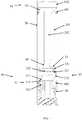
- FIG. 2is an exploded schematic diagram of the electronic cigarette atomizer.
- An electronic cigarette atomizercomprises an atomizing assembly 30, a smoke duct 20 and a cigarette holder 10.
- the smoke duct 20comprises a liquid storage cavity 201 for storing tobacco liquid and a flue 202, and is in a fitted mounting respectively with the atomizing assembly 30 and the cigarette holder 101.
- the atomizing assembly 30comprises a holding frame 31 and a heating module 32.
- the holding frame 31comprises an air channel communicated with the flue 202 and end-surface slots for accommodating the heating module 32.
- the heating module 32comprises a ceramic base body 321 and a heating wire 322 wound on the ceramic base body.
- the heating wire 322is electrically connected with the holding frame 31, and the ceramic base body 321 is of a hollow micropore structure and is communicated with the liquid storage cavity 201.
- the ceramic base body 321is communicated with the liquid storage cavity 201.
- air in the ceramic base body 321is driven and the tobacco liquid is made to flow into the hollow micropore structure of the ceramic base body 321.
- the heating wire 322is energized to heat, the tobacco liquid is heated and atomized into smoke, which passes through the ceramic base body 321 and flows into the air channel to pass through the flue 202 along with the air and flow out at the cigarette holder 10.
- the flue 202is preferably disposed in the center of the smoke duct 20; and an inner side wall of the smoke duct 20 and an outer side wall of the flue 202 form the liquid storage cavity 201, specifically, the inner side wall of the smoke duct 20, the outer side wall of the flue 202, the inner side surface of the cigarette holder 10 and the atomizing assembly 30 form the liquid storage cavity 201.
- the cigarette holder 10comprises a cigarette holder cover 101 and a cigarette holder cap 102, which also comprise cigarette holder ports communicated with the flue 202.
- the cigarette holder cover 101is used for sealing the liquid storage cavity 201 and connected with the flue 202.
- the cigarette holder cover 101also comprises a lateral groove for sealing a first seal ring 401 to improve the tightness of the liquid storage cavity 201.
- the cigarette holder cap 102is made of a plastic material to facilitate smoking.
- the electronic cigarette atomizeralso comprises an adapter ring 50, which is used for fixing the holding frame 31 and the smoke duct 20, adapting other assemblies of the electronic cigarette atomizer and also wrapping the holding frame 31.
- the holding frame 31is used to prevent electric leakage.
- the adapter ring 50comprises an air inlet to facilitate smoking.
- the air channelmainly refers to a hollow structure consisting of the adapter ring 50 and the holding frame 31.
- the air channelis communicated with the flue 202, the cigarette holder port and the air inlet, so that the air follows the air inlet into the air channel and drives the smoke which is atomized on the heating module 32 to enter an oral cavity of a human body from the cigarette holder port along the flue 202.
- FIG. 3is a structural schematic diagram of the holding frame of the electronic cigarette atomizer.
- the holding frame 31comprises an outer holding frame 313, a middle holding frame 312 and an inner holding frame 311, which are in a fitted mounting from outside to inside.
- the outer holding frame 313 and the inner holding frame 311are conductive holding frames.
- the middle holding frame 312is an insulating holding frame and nested between the outer holding frame 313 and the inner holding frame 311 for insulating and isolating the outer holding frame 313 and the inner holding frame 311 and sealing the liquid storage cavity.
- outer holding frame 313 and the inner holding frame 311are conductive, two ends of the heating wire 322 are electrically connected with the outer holding frame 313 and the inner holding frame 311 respectively.
- the outer holding frame 313 and the inner holding frame 311are provided with opposite electrodes. For example, a current flows to the heating wire 322 from the outer holding frame 313 and then flows to the inner holding frame 311 from the heating wire 322, whereby the heating wire 322 heats after being energized.
- the present inventionis implemented by the end-surface slots disposed in the holding frame 31.
- the end-surface slotsare respectively disposed at two sides of an end-surface for the outer holding frame 313, the middle holding frame 312 and the inner holding frame 311.
- the end-surfaceis a side surface for accommodating the heating module 32. Since the heating module 32 takes the shape of a cylinder, the end-surface slots are disposed on the same axis when the outer holding frame 313, the middle holding frame 312 and the inner holding frame 311 are in a fitted mounting. Naturally, if the heating module 32 takes other shapes, the end-surface slots are disposed at corresponding positions.
- the end-surface slots of the outer holding frame 313 and the inner holding frame 311comprise a large end-surface slot and a small end-surface slot respectively.
- the large end-surface slot of the outer holding frame 313 and the small end-surface slot of the inner holding frame 311are disposed on the same side.
- the heating module 32is placed on the holding frame 31, at one side surface in which the large end-surface slot of the outer holding frame 313 and the small end-surface slot of the inner holding frame 311 are disposed.
- the ceramic base body 321is clamped and sleeved on the small end-surface slot of the inner holding frame 311.
- the heating wire 322is electrically connected with the inner holding frame 311.
- the heating wire 322is not electrically connected with the outer holding frame 313; and similarly.
- the heating wire 322 at the other sideis connected with the outer holding frame 313. Namely, one end of the heating wire 322 is electrically connected with the outer holding frame 313, and the other end is electrically connected with the inner holding frame 311 to form an energization circuit.
- the end-surface slotsare preferably U-shaped slots.
- the outer holding frame 313also comprises a threaded structure for fitted connection with an adapter ring 50, a lateral groove for mounting a second seal ring 402 to improve the tightness of the liquid storage cavity 201.
- the outer holding frame 313is in a fitted mounting respectively with the adapter ring 50 to support the inner holding frame 312 and the inner holding frame 311.
- FIG. 4is a structural schematic diagram of the heating module of the electronic cigarette atomizer
- FIG. 5is an exploded schematic diagram of the heating module of the electronic cigarette atomizer.
- the heating module 32also comprises connecting terminals 323 disposed on two ends of the ceramic base body 321.
- the connecting terminals 323comprise a first connecting terminal 3231 and a second connecting terminal 3232, which are disposed at two sides.
- the ceramic base body 321is abutted against the end-surface slots through the connecting terminals 323.
- the connecting terminals 323are conductors.
- the heating wire 322is connected with the connecting terminals 323 and is electrically connected with the outer holding frame 313 and the inner holding frame 311 through the connecting terminals 323 respectively.
- the connecting terminals 323comprise terminal through holes fitted with the hollow micropore structure of the ceramic base body 321.
- the hollow micropore structure of the ceramic base body 321is communicated with the liquid storage cavity 201 through the connecting terminals 323.
- FIG. 6is a structural schematic diagram of the holding frame and heating module of the electronic cigarette atomizer.
- the first connecting terminal 3231is connected with the small end-surface slot of the inner holding frame 311 and is energized with the inner holding frame 31
- the second connecting terminal 3232is connected with the small end-surface slot of the outer holding frame 313 and is energized with the outer holding frame 313.
- the atomizing assembly 30also comprises an upper cover 33 in a fitted mounting with the smoke duct 20.
- the upper cover 33comprises an upper cover through hole; the heating module 32 is disposed between the upper cover 33 and the holding frame 31.
- the air channelis connected with the flue 202 through the upper cover through hole.
- the upper cover 33comprises an inner plastic pad 331, which is in a fitted mounting with the heating module 32 and the middle holding frame 312 respectively.
- An end section of the upper cover 33is provided with a U-shaped slot fitted with the heating module 32 and the middle holding frame 312.
- the end section of the upper cover 33is in a fitted mounting with the flue 202, and is locked and sealed through an O-shaped gasket 60 to prevent the tobacco liquid from flowing backward.
- an assembling process of the electronic cigarette atomizeris approximately as follows: first, the heating wire 322 is wound on the ceramic base body 321; next, the connecting terminals 323 are connected onto the ceramic base body 321; then the ceramic base body 321 together with the heating wire 322 and the connecting terminals 323 are mounted into the two end-surface slots of the holding frame 31 which is obtained by nesting the outer holding frame 313, the middle holding frame 312 and the inner holding frame 311.
- a power supplyis mounted on the outer holding frame 313 and the inner holding frame 311 and is connected with the heating wire 322 (through the connecting terminals 323); and then, the upper cover 33.
- the smoke duct 20, the cigarette holder cover 101 and the adapter ring 50are mounted to complete the mounting operation.
- An assembling sequence of the electronic cigarette atomizermay also be appropriately adjusted as required to facilitate the implementation of the full-automatic production.
- the description aboveshall not be construed as limiting the scope of the present invention but as merely providing preferred embodiments of the present invention
Landscapes
- Electrostatic Spraying Apparatus (AREA)
- Resistance Heating (AREA)
Description
- The present invention relates to the technical field of electronic cigarettes, and in particular to an electronic cigarette atomizer.
- An electronic cigarette, also called an e-cigarette, is mainly used for smoking cessation and used as an alternative to cigarettes. The electronic cigarette is similar to a cigarette in appearance and smell, but generally does not contain tar, suspended particulates and other harmful components as contained in the cigarette, thereby producing no pervasive or swirling second-hand smoke.
- The electronic cigarette mainly consists of an atomizer and a power supply assembly. The atomizer generally comprises a liquid storage cavity, a heating wire, a heating wire support body (a liquid absorbing rope), positive and negative atomizer electrodes and the like. In a common electronic cigarette, the heating wire is wound on the heating wire support body to form a heating element. Therein, two ends of the heating wire are electrically connected with the positive and negative atomizer electrodes via through holes in a holding frame to implement heating operation.
- However, the connecting manner of the heating element leads to instability in energization. Specifically, it is troublesome to mount the heating wire and the positive and negative atomizer electrodes. The electronic cigarette atomizer is complicated in structure and inconvenient for fully-automatic production of the electronic cigarette atomizer.
US 2013/0228191 A1 discloses an electronic cigarette including an elongated housing that has a mouthpiece with an aerosol outlet and an atomizer disposed within an atomizing chamber. The atomizer is wound on a wick which is configured to transfer the liquid by capillarity from the liquid reservoir to the atomizer.CN 104161308 A discloses a heating module of an electronic cigarette atomizer in which the heating wire is wound around the ceramic rod.- A technical problem to be solved by the present invention is to overcome the above deficiencies in the prior art and provide an electronic cigarette atomizer, which is strong in stability, simple in structure and convenient for automatic production.
- A technical solution employed by the present invention to solve the technical problem is described in claim 1.
- Therein, a preferred solution is as follows: the end-surface slots are respectively disposed at two sides of an end-surface for the outer holding frame, the middle holding frame and the inner holding frame, and are disposed on the same axis when the outer holding frame, the middle holding frame and the inner holding frame are in a fitted mounting.
- Therein, a preferred solution is as follows: the end-surface slots of the outer holding frame and the inner holding frame comprise a large end-surface slot and a small end-surface slot respectively, and the large end-surface slot of the outer holding frame and the small end-surface slot of the inner holding frame are disposed on the same side.
- Therein, a preferred solution is as follows: the end-surface slots are U-shaped slots.
- Therein, a preferred solution is as follows: the atomizing assembly also comprises an upper cover in a fitted mounting with the smoke duct; the upper cover comprises an upper cover through hole; the heating module is disposed between the upper cover and the holding frame; and the air channel is connected with the flue through the upper cover through hole.
- Therein, a preferred solution is as follows: the upper cover comprises an inner plastic pad, which is in a fitted mounting respectively with the heating module and the middle holding frame.
- Therein, a preferred solution is as follows: the heating module also comprises connecting terminals disposed at two ends of the ceramic base body, and the heating wire is connected with the connecting terminals and is electrically connected with the outer holding frame and the inner holding frame through the connecting terminals respectively.
- Therein, a preferred solution is as follows: the connecting terminals comprise terminal through holes fitted with the hollow micropore structure of the ceramic base body.
- The present invention has the advantageous effects that compared with the prior art, with the design of the outer and inner conductive holding frames in the present invention, the heating module is abutted against and electrically connected with the outer and inner holding frames respectively, thereby simplifying the structure of the electronic cigarette atomizer and increasing the stability of the electronic cigarette atomizer; moreover, with the middle holding frame and an inner plastic pad for sealing and isolating the heating module, the tightness of the electronic cigarette atomizer is improved; and the electronic cigarette atomizer is simple in structure and convenient to mount, thereby facilitating full-automatic production and increasing production efficiency.
- The present invention will be further described below with reference to the attached drawings and the embodiments, in which:
FIG. 1 is a cross-section schematic diagram of an electronic cigarette atomizer of the present invention;FIG. 2 is an exploded schematic diagram of the electronic cigarette atomizer of the present invention;FIG. 3 is a structural schematic diagram of a holding frame of the electronic cigarette atomizer of the present invention;FIG. 4 is a structural schematic diagram of a heating module of the electronic cigarette atomizer of the present invention;FIG. 5 is an exploded schematic diagram of the heating module of the electronic cigarette atomizer of the present invention; andFIG. 6 is a structural schematic diagram of the holding frame and heating module of the electronic cigarette atomizer of the present invention.- Preferred embodiments of the present invention will now be described in detail with reference to the attached drawings.
- As shown in
FIG. 1 andFIG. 2 , the present invention provides a preferred embodiment of an electronic cigarette atomizer to improve the stability of the electronic cigarette atomizer and facilitate fully-automatic production. Where,FIG. 1 is a cross-section schematic diagram of the electronic cigarette atomizer, andFIG. 2 is an exploded schematic diagram of the electronic cigarette atomizer. - An electronic cigarette atomizer comprises an atomizing
assembly 30, asmoke duct 20 and acigarette holder 10. Thesmoke duct 20 comprises aliquid storage cavity 201 for storing tobacco liquid and aflue 202, and is in a fitted mounting respectively with the atomizingassembly 30 and thecigarette holder 101. The atomizingassembly 30 comprises aholding frame 31 and aheating module 32. Theholding frame 31 comprises an air channel communicated with theflue 202 and end-surface slots for accommodating theheating module 32. Theheating module 32 comprises aceramic base body 321 and aheating wire 322 wound on the ceramic base body. Theheating wire 322 is electrically connected with theholding frame 31, and theceramic base body 321 is of a hollow micropore structure and is communicated with theliquid storage cavity 201. - The
ceramic base body 321 is communicated with theliquid storage cavity 201. When a user smokes through thecigarette holder 10, air in theceramic base body 321 is driven and the tobacco liquid is made to flow into the hollow micropore structure of theceramic base body 321. Under this state, after theheating wire 322 is energized to heat, the tobacco liquid is heated and atomized into smoke, which passes through theceramic base body 321 and flows into the air channel to pass through theflue 202 along with the air and flow out at thecigarette holder 10. - The
flue 202 is preferably disposed in the center of thesmoke duct 20; and an inner side wall of thesmoke duct 20 and an outer side wall of theflue 202 form theliquid storage cavity 201, specifically, the inner side wall of thesmoke duct 20, the outer side wall of theflue 202, the inner side surface of thecigarette holder 10 and the atomizingassembly 30 form theliquid storage cavity 201. - The
cigarette holder 10 comprises acigarette holder cover 101 and acigarette holder cap 102, which also comprise cigarette holder ports communicated with theflue 202. Thecigarette holder cover 101 is used for sealing theliquid storage cavity 201 and connected with theflue 202. Thecigarette holder cover 101 also comprises a lateral groove for sealing afirst seal ring 401 to improve the tightness of theliquid storage cavity 201. Thecigarette holder cap 102 is made of a plastic material to facilitate smoking. - The electronic cigarette atomizer also comprises an
adapter ring 50, which is used for fixing theholding frame 31 and thesmoke duct 20, adapting other assemblies of the electronic cigarette atomizer and also wrapping theholding frame 31. Theholding frame 31 is used to prevent electric leakage. Theadapter ring 50 comprises an air inlet to facilitate smoking. - The air channel mainly refers to a hollow structure consisting of the
adapter ring 50 and theholding frame 31. The air channel is communicated with theflue 202, the cigarette holder port and the air inlet, so that the air follows the air inlet into the air channel and drives the smoke which is atomized on theheating module 32 to enter an oral cavity of a human body from the cigarette holder port along theflue 202. - Further, with reference to
FIG. 3 , a preferred embodiment of theholding frame 31 is provided.FIG. 3 is a structural schematic diagram of the holding frame of the electronic cigarette atomizer. - The
holding frame 31 comprises anouter holding frame 313, amiddle holding frame 312 and aninner holding frame 311, which are in a fitted mounting from outside to inside. Theouter holding frame 313 and theinner holding frame 311 are conductive holding frames. Themiddle holding frame 312 is an insulating holding frame and nested between theouter holding frame 313 and theinner holding frame 311 for insulating and isolating theouter holding frame 313 and theinner holding frame 311 and sealing the liquid storage cavity. - Since the
outer holding frame 313 and theinner holding frame 311 are conductive, two ends of theheating wire 322 are electrically connected with theouter holding frame 313 and theinner holding frame 311 respectively. Theouter holding frame 313 and theinner holding frame 311 are provided with opposite electrodes. For example, a current flows to theheating wire 322 from theouter holding frame 313 and then flows to theinner holding frame 311 from theheating wire 322, whereby theheating wire 322 heats after being energized. - To guarantee the normal flowing of the current and prevent short circuiting, the present invention is implemented by the end-surface slots disposed in the holding
frame 31. Specifically, the end-surface slots are respectively disposed at two sides of an end-surface for theouter holding frame 313, themiddle holding frame 312 and theinner holding frame 311. the end-surface is a side surface for accommodating theheating module 32. Since theheating module 32 takes the shape of a cylinder, the end-surface slots are disposed on the same axis when theouter holding frame 313, themiddle holding frame 312 and theinner holding frame 311 are in a fitted mounting. Naturally, if theheating module 32 takes other shapes, the end-surface slots are disposed at corresponding positions. - Further, the end-surface slots of the
outer holding frame 313 and theinner holding frame 311 comprise a large end-surface slot and a small end-surface slot respectively. The large end-surface slot of theouter holding frame 313 and the small end-surface slot of theinner holding frame 311 are disposed on the same side. When theheating module 32 is placed on the holdingframe 31, at one side surface in which the large end-surface slot of theouter holding frame 313 and the small end-surface slot of theinner holding frame 311 are disposed. Theceramic base body 321 is clamped and sleeved on the small end-surface slot of theinner holding frame 311. Theheating wire 322 is electrically connected with theinner holding frame 311. But, the large end-surface slot of theouter holding frame 313 cannot be connected with theceramic base body 321. Theheating wire 322 is not electrically connected with theouter holding frame 313; and similarly. Theheating wire 322 at the other side is connected with theouter holding frame 313. Namely, one end of theheating wire 322 is electrically connected with theouter holding frame 313, and the other end is electrically connected with theinner holding frame 311 to form an energization circuit. - To facilitate the production and mounting of the
heating module 32 and realize automatic mounting, the end-surface slots are preferably U-shaped slots. - The
outer holding frame 313 also comprises a threaded structure for fitted connection with anadapter ring 50, a lateral groove for mounting asecond seal ring 402 to improve the tightness of theliquid storage cavity 201. Theouter holding frame 313 is in a fitted mounting respectively with theadapter ring 50 to support theinner holding frame 312 and theinner holding frame 311. - With reference to
FIG. 4 and FIG. 5 , a preferred embodiment of a heating module is provided.FIG. 4 is a structural schematic diagram of the heating module of the electronic cigarette atomizer, andFIG. 5 is an exploded schematic diagram of the heating module of the electronic cigarette atomizer. - The
heating module 32 also comprises connectingterminals 323 disposed on two ends of theceramic base body 321. The connectingterminals 323 comprise a first connectingterminal 3231 and a second connectingterminal 3232, which are disposed at two sides. Theceramic base body 321 is abutted against the end-surface slots through the connectingterminals 323. The connectingterminals 323 are conductors. Theheating wire 322 is connected with the connectingterminals 323 and is electrically connected with theouter holding frame 313 and theinner holding frame 311 through the connectingterminals 323 respectively. - The connecting
terminals 323 comprise terminal through holes fitted with the hollow micropore structure of theceramic base body 321. The hollow micropore structure of theceramic base body 321 is communicated with theliquid storage cavity 201 through the connectingterminals 323. - As shown in
FIG. 6 , the present invention provides a preferred embodiment for the mounting of the holding frame and heating module.FIG. 6 is a structural schematic diagram of the holding frame and heating module of the electronic cigarette atomizer. - When the
heating module 32 is placed on the holdingframe 31, the first connectingterminal 3231 is connected with the small end-surface slot of theinner holding frame 311 and is energized with theinner holding frame 311, and the second connectingterminal 3232 is connected with the small end-surface slot of theouter holding frame 313 and is energized with theouter holding frame 313. - In the present invention, the atomizing
assembly 30 also comprises anupper cover 33 in a fitted mounting with thesmoke duct 20. Theupper cover 33 comprises an upper cover through hole; theheating module 32 is disposed between theupper cover 33 and the holdingframe 31. The air channel is connected with theflue 202 through the upper cover through hole. - The
upper cover 33 comprises aninner plastic pad 331, which is in a fitted mounting with theheating module 32 and themiddle holding frame 312 respectively. An end section of theupper cover 33 is provided with a U-shaped slot fitted with theheating module 32 and themiddle holding frame 312. - The end section of the
upper cover 33 is in a fitted mounting with theflue 202, and is locked and sealed through an O-shapedgasket 60 to prevent the tobacco liquid from flowing backward. - In the present invention, an assembling process of the electronic cigarette atomizer is approximately as follows: first, the
heating wire 322 is wound on theceramic base body 321; next, the connectingterminals 323 are connected onto theceramic base body 321; then theceramic base body 321 together with theheating wire 322 and the connectingterminals 323 are mounted into the two end-surface slots of the holdingframe 31 which is obtained by nesting theouter holding frame 313, themiddle holding frame 312 and theinner holding frame 311. A power supply is mounted on theouter holding frame 313 and theinner holding frame 311 and is connected with the heating wire 322 (through the connecting terminals 323); and then, theupper cover 33. Thesmoke duct 20, thecigarette holder cover 101 and theadapter ring 50 are mounted to complete the mounting operation. An assembling sequence of the electronic cigarette atomizer may also be appropriately adjusted as required to facilitate the implementation of the full-automatic production. The description above shall not be construed as limiting the scope of the present invention but as merely providing preferred embodiments of the present invention.
Claims (8)
- An electronic cigarette atomizer, comprising:an atomizing assembly (30),a smoke duct (20), anda cigarette holder (10),wherein the smoke duct (20) comprises a liquid storage cavity (201) for storing tobacco liquid and a flue (202); the smoke duct (20) is cooperatively mounted respectively with the atomizing assembly (30) and the cigarette holder (10),
wherein the atomizing assembly (30) comprises: a holding frame (31), comprising an air channel communicated with the flue (202) and end-surface slots for accommodating a heating module (32); and
the heating module (32), comprising a base body (321) and a heating wire (322) wound on the base body (321), wherein the heating wire (322) is electrically connected with the holding frame (31), and the base body (321) is communicated with the liquid storage cavity (201),
characterized in that
said base body (321) is a ceramic base body of a hollow micropore structure,
the holding frame (31) comprises an outer holding frame (313), a middle holding frame (312) and an inner holding frame (311), wherein the outer holding frame (313) and the inner holding frame(311) are conductive holding frames, and the middle holding frame (312) is an insulating holding frame and nested between the outer holding frame (313) and the inner holding frame (311) for insulating and isolating the outer holding frame (313) and the inner holding frame (311) and sealing the liquid storage cavity (201), and
two ends of the heating wire (322) are electrically connected with the end-surface slots of the outer holding frame and the inner holding frame respectively, and the outer holding frame (313) and the inner holding frame (311) are provided with opposite electrodes. - The electronic cigarette atomizer according to claim 1, wherein the end-surface slots are respectively disposed at two sides of an end-surface of the outer holding frame (313), the middle holding frame (312) and the inner holding frame (311); and the end-surface slots are disposed on a same axis when the outer holding frame (313), the middle holding frame (312) and the inner holding frame (311) are cooperatively mounted.
- The electronic cigarette atomizer according to claim 2, wherein the end-surface slots of the outer holding frame (313) and the inner holding frame (311) comprise a large end-surface slot and a small end-surface slot respectively, and the large end-surface slot of the outer holding frame (313) and the small end-surface slot of the inner holding frame (311) are disposed on a same side.
- The electronic cigarette atomizer according to any one of claims 1-3, wherein the end-surface slots are U-shaped slots.
- The electronic cigarette atomizer according to claim 1, wherein the atomizing assembly (30) further comprises an upper cover (33) in a fitted mounting with the smoke duct (20); the upper cover (33) comprises an upper cover (33) through hole; the heating module (32) is disposed between the upper cover (33) and the holding frame (31); and the air channel is connected with the flue through the upper cover (33) through hole.
- The electronic cigarette atomizer according to claim 5, wherein the upper cover (33) comprises an inner plastic pad (331), which is in a fitted mounting respectively with the heating module (32) and the middle holding frame (312).
- The electronic cigarette atomizer according to claim 3, wherein the heating module (32) further comprises connecting terminals (323) disposed at two ends of the ceramic base body (321); the heating wire (32) is connected with the connecting terminals (323) and is electrically connected with the outer holding frame (313) and the inner holding frame (311) respectively through the connecting terminals (323).
- The electronic cigarette atomizer according to claim 7, wherein the connecting terminals (323) comprise terminal through holes fitted with the hollow micropore structure of the ceramic base body (321).
Applications Claiming Priority (1)
| Application Number | Priority Date | Filing Date | Title |
|---|---|---|---|
| PCT/CN2015/072311WO2016123775A1 (en) | 2015-02-05 | 2015-02-05 | E-cigarette atomizer |
Publications (3)
| Publication Number | Publication Date |
|---|---|
| EP3153036A1 EP3153036A1 (en) | 2017-04-12 |
| EP3153036A4 EP3153036A4 (en) | 2017-09-13 |
| EP3153036B1true EP3153036B1 (en) | 2019-11-13 |
Family
ID=56563321
Family Applications (1)
| Application Number | Title | Priority Date | Filing Date |
|---|---|---|---|
| EP15880731.3AActiveEP3153036B1 (en) | 2015-02-05 | 2015-02-05 | E-cigarette atomizer |
Country Status (3)
| Country | Link |
|---|---|
| US (1) | US10477895B2 (en) |
| EP (1) | EP3153036B1 (en) |
| WO (1) | WO2016123775A1 (en) |
Families Citing this family (44)
| Publication number | Priority date | Publication date | Assignee | Title |
|---|---|---|---|---|
| US20160345631A1 (en) | 2005-07-19 | 2016-12-01 | James Monsees | Portable devices for generating an inhalable vapor |
| US9155321B2 (en) | 2010-08-11 | 2015-10-13 | R.J. Reynolds Tobacco Company | Meltable smokeless tobacco composition |
| US11116237B2 (en) | 2010-08-11 | 2021-09-14 | R.J. Reynolds Tobacco Company | Meltable smokeless tobacco composition |
| US10279934B2 (en) | 2013-03-15 | 2019-05-07 | Juul Labs, Inc. | Fillable vaporizer cartridge and method of filling |
| CN203435687U (en)* | 2013-08-31 | 2014-02-19 | 卓尔悦(常州)电子科技有限公司 | Atomizing head |
| USD825102S1 (en) | 2016-07-28 | 2018-08-07 | Juul Labs, Inc. | Vaporizer device with cartridge |
| US20160366947A1 (en) | 2013-12-23 | 2016-12-22 | James Monsees | Vaporizer apparatus |
| US10076139B2 (en) | 2013-12-23 | 2018-09-18 | Juul Labs, Inc. | Vaporizer apparatus |
| USD842536S1 (en) | 2016-07-28 | 2019-03-05 | Juul Labs, Inc. | Vaporizer cartridge |
| DE202014011260U1 (en) | 2013-12-23 | 2018-11-13 | Juul Labs Uk Holdco Limited | Systems for an evaporation device |
| US10159282B2 (en) | 2013-12-23 | 2018-12-25 | Juul Labs, Inc. | Cartridge for use with a vaporizer device |
| US10058129B2 (en) | 2013-12-23 | 2018-08-28 | Juul Labs, Inc. | Vaporization device systems and methods |
| MX394125B (en) | 2014-12-05 | 2025-03-24 | Juul Labs Inc | CALIBRATED DOSE CONTROL |
| CN204444245U (en)* | 2015-01-05 | 2015-07-08 | 深圳市合元科技有限公司 | Removable atomization unit and the atomizer and the electronic cigarette that comprise this atomization unit |
| WO2016123775A1 (en)* | 2015-02-05 | 2016-08-11 | 昂纳自动化技术(深圳)有限公司 | E-cigarette atomizer |
| EP3413960B1 (en) | 2016-02-11 | 2021-03-31 | Juul Labs, Inc. | Fillable vaporizer cartridge and method of filling |
| CO2018009342A2 (en) | 2016-02-11 | 2018-09-20 | Juul Labs Inc | Secure fixing cartridges for vaporizing devices |
| US10405582B2 (en) | 2016-03-10 | 2019-09-10 | Pax Labs, Inc. | Vaporization device with lip sensing |
| CN205461048U (en)* | 2016-03-22 | 2016-08-17 | 深圳市赛尔美电子科技有限公司 | Integrated liquid injection evaporation container |
| USD849996S1 (en) | 2016-06-16 | 2019-05-28 | Pax Labs, Inc. | Vaporizer cartridge |
| USD851830S1 (en) | 2016-06-23 | 2019-06-18 | Pax Labs, Inc. | Combined vaporizer tamp and pick tool |
| USD836541S1 (en) | 2016-06-23 | 2018-12-25 | Pax Labs, Inc. | Charging device |
| US11660403B2 (en) | 2016-09-22 | 2023-05-30 | Juul Labs, Inc. | Leak-resistant vaporizer device |
| JP6945629B2 (en) | 2016-12-12 | 2021-10-06 | ブイエムアール・プロダクツ・リミテッド・ライアビリティ・カンパニーVmr Products Llc | Vaporizer cartridge |
| US10285444B2 (en)* | 2017-04-27 | 2019-05-14 | Rai Strategic Holdings, Inc. | Aerosol delivery device including a ceramic wicking element |
| CN109419038B (en)* | 2017-08-25 | 2021-05-18 | 卓尔悦欧洲控股有限公司 | Upper cover subassembly, atomizer and electron cigarette |
| GB201714300D0 (en)* | 2017-09-06 | 2017-10-18 | British American Tobacco Investments Ltd | Vapour provision systems |
| USD887632S1 (en) | 2017-09-14 | 2020-06-16 | Pax Labs, Inc. | Vaporizer cartridge |
| US20200077703A1 (en)* | 2018-09-11 | 2020-03-12 | Rai Strategic Holdings, Inc. | Wicking element for aerosol delivery device |
| CN109247622B (en)* | 2018-09-25 | 2024-05-03 | 襄阳申冠机电技术有限公司 | Heating electronic cigarette |
| GB201818080D0 (en)* | 2018-11-06 | 2018-12-19 | Nicoventures Trading Ltd | Vapour provision systems |
| CN209546930U (en)* | 2018-12-13 | 2019-10-29 | 常州市派腾电子技术服务有限公司 | Atomizing head, atomizer and electronic cigarette |
| DE102019103989A1 (en)* | 2019-02-18 | 2020-08-20 | Hauni Maschinenbau Gmbh | Consumption unit, inhaler and manufacturing process |
| WO2021004139A1 (en)* | 2019-07-10 | 2021-01-14 | 东莞市阿尔法电子科技有限公司 | Closed body and cartridge |
| WO2021016852A1 (en)* | 2019-07-30 | 2021-02-04 | 深圳雾芯科技有限公司 | Atomization device |
| KR102386859B1 (en)* | 2019-07-30 | 2022-04-14 | 주식회사 케이티앤지 | An atomizer and a cartridge comprising thereof |
| CA3162544A1 (en) | 2019-12-23 | 2021-07-01 | Pax Labs, Inc. | Vaporizer cartridge |
| WO2021138830A1 (en)* | 2020-01-08 | 2021-07-15 | 深圳雾芯科技有限公司 | Atomization device |
| CN111317175A (en)* | 2020-04-07 | 2020-06-23 | 深圳市康泓威科技有限公司 | Electronic atomizer with V-shaped ceramic atomizing core |
| CN111317182A (en)* | 2020-04-07 | 2020-06-23 | 深圳市康泓威科技有限公司 | Atomization assembly of electronic atomization device |
| CN114504126A (en)* | 2020-11-17 | 2022-05-17 | 深圳市合元科技有限公司 | Atomizers and Electronic Atomizers |
| US12213517B2 (en)* | 2021-01-13 | 2025-02-04 | Sobota HnB Technologies LLC | Vaporizer for smoking cigarettes with individual heater |
| USD1028336S1 (en) | 2021-06-22 | 2024-05-21 | Pax Labs, Inc. | Vaporizer cartridge |
| WO2023123064A1 (en)* | 2021-12-29 | 2023-07-06 | 深圳尊一品科技有限公司 | Sealing member, atomizer, and inhalable device |
Family Cites Families (12)
| Publication number | Priority date | Publication date | Assignee | Title |
|---|---|---|---|---|
| WO2014198157A1 (en)* | 2013-06-13 | 2014-12-18 | Shenzhen Kanger Technology Co., Ltd. | Ceramic heating elements for electronic cigarettes |
| US8528569B1 (en)* | 2011-06-28 | 2013-09-10 | Kyle D. Newton | Electronic cigarette with liquid reservoir |
| US9101729B2 (en)* | 2012-06-05 | 2015-08-11 | Huizou Kimree Technology Co., Ltd., Shenzhen Branch | Electronic cigarette and inhaling shell thereof |
| CN103960781A (en)* | 2013-09-29 | 2014-08-06 | 深圳市麦克韦尔科技有限公司 | Electronic cigarette |
| US10292424B2 (en)* | 2013-10-31 | 2019-05-21 | Rai Strategic Holdings, Inc. | Aerosol delivery device including a pressure-based aerosol delivery mechanism |
| CN203633505U (en)* | 2013-11-29 | 2014-06-11 | 深圳市合元科技有限公司 | Atomizer for electronic cigarette and electronic cigarette |
| CN106455691B (en)* | 2014-04-08 | 2019-05-17 | 吉瑞高新科技股份有限公司 | Atomizer and electronic cigarette |
| CN203986100U (en)* | 2014-06-03 | 2014-12-10 | 深圳市施美乐科技有限公司 | Electronic smoke atomizer and electronic cigarette |
| CN104161308A (en)* | 2014-09-04 | 2014-11-26 | 昂纳自动化技术(深圳)有限公司 | Heating module of electronic cigarette atomizer |
| WO2016123775A1 (en)* | 2015-02-05 | 2016-08-11 | 昂纳自动化技术(深圳)有限公司 | E-cigarette atomizer |
| US11000069B2 (en)* | 2015-05-15 | 2021-05-11 | Rai Strategic Holdings, Inc. | Aerosol delivery device and methods of formation thereof |
| KR101844882B1 (en)* | 2016-08-08 | 2018-04-03 | 엘지전자 주식회사 | Heating module and Heat assembly having the same |
- 2015
- 2015-02-05WOPCT/CN2015/072311patent/WO2016123775A1/ennot_activeCeased
- 2015-02-05EPEP15880731.3Apatent/EP3153036B1/enactiveActive
- 2016
- 2016-09-20USUS15/270,014patent/US10477895B2/ennot_activeExpired - Fee Related
Non-Patent Citations (1)
| Title |
|---|
| None* |
Also Published As
| Publication number | Publication date |
|---|---|
| EP3153036A4 (en) | 2017-09-13 |
| US20170006922A1 (en) | 2017-01-12 |
| WO2016123775A1 (en) | 2016-08-11 |
| US10477895B2 (en) | 2019-11-19 |
| EP3153036A1 (en) | 2017-04-12 |
Similar Documents
| Publication | Publication Date | Title |
|---|---|---|
| EP3153036B1 (en) | E-cigarette atomizer | |
| US10512284B2 (en) | Atomizer of electronic cigarette | |
| US10973087B2 (en) | E-cigarette with a plurality of heating components | |
| US20180317559A1 (en) | Atomizing head, atomizer and electronic cigarette thereof | |
| CN204444245U (en) | Removable atomization unit and the atomizer and the electronic cigarette that comprise this atomization unit | |
| CN206079041U (en) | Atomizer and including split type electron cigarette of this atomizer | |
| US9301549B2 (en) | Electronic cigarette device, electronic cigarette and atomization device thereof | |
| CN103763952B (en) | Electronic cigarette suction nozzle | |
| US10306930B2 (en) | Heating device, and atomizing head, atomizer and electronic cigarette having the same | |
| CN204232296U (en) | Nicotinic liquid atomizer and comprise the smoking apparatus of this nicotinic liquid atomizer | |
| CN206079042U (en) | Conducting structure and applied this conducting structure's split type electron cigarette | |
| CN206651392U (en) | Atomising head, atomizer and electronic cigarette | |
| CN207011683U (en) | Atomizer and its electronic cigarette | |
| CN210869884U (en) | Atomizers and Electronic Cigarettes | |
| CN104605482A (en) | Replaceable atomization unit and atomizer and electronic cigarette including the same | |
| CN106983177B (en) | Electronic cigarette and its atomizing device | |
| CN105768225A (en) | Smoke bomb and electronic cigarette using it | |
| WO2016011574A1 (en) | Electronic cigarette | |
| CN105747282B (en) | Atomizer and its electronic cigarette | |
| WO2014089757A1 (en) | Electronic cigarette and electronic cigarette device thereof | |
| WO2014153782A1 (en) | Electronic cigarette | |
| CN114340418B (en) | Atomizer for electronic cigarette and electronic cigarette | |
| CN210471007U (en) | Atomizing components and electronic cigarettes | |
| CN108618204A (en) | Atomizer and electronic cigarette | |
| CN207125320U (en) | Atomising head, atomizer and electronic cigarette |
Legal Events
| Date | Code | Title | Description |
|---|---|---|---|
| STAA | Information on the status of an ep patent application or granted ep patent | Free format text:STATUS: THE INTERNATIONAL PUBLICATION HAS BEEN MADE | |
| PUAI | Public reference made under article 153(3) epc to a published international application that has entered the european phase | Free format text:ORIGINAL CODE: 0009012 | |
| STAA | Information on the status of an ep patent application or granted ep patent | Free format text:STATUS: REQUEST FOR EXAMINATION WAS MADE | |
| 17P | Request for examination filed | Effective date:20170104 | |
| AK | Designated contracting states | Kind code of ref document:A1 Designated state(s):AL AT BE BG CH CY CZ DE DK EE ES FI FR GB GR HR HU IE IS IT LI LT LU LV MC MK MT NL NO PL PT RO RS SE SI SK SM TR | |
| AX | Request for extension of the european patent | Extension state:BA ME | |
| A4 | Supplementary search report drawn up and despatched | Effective date:20170816 | |
| RIC1 | Information provided on ipc code assigned before grant | Ipc:A24F 47/00 20060101AFI20170809BHEP Ipc:H05B 3/00 20060101ALI20170809BHEP | |
| STAA | Information on the status of an ep patent application or granted ep patent | Free format text:STATUS: EXAMINATION IS IN PROGRESS | |
| 17Q | First examination report despatched | Effective date:20180406 | |
| DAX | Request for extension of the european patent (deleted) | ||
| GRAP | Despatch of communication of intention to grant a patent | Free format text:ORIGINAL CODE: EPIDOSNIGR1 | |
| STAA | Information on the status of an ep patent application or granted ep patent | Free format text:STATUS: GRANT OF PATENT IS INTENDED | |
| INTG | Intention to grant announced | Effective date:20190531 | |
| GRAS | Grant fee paid | Free format text:ORIGINAL CODE: EPIDOSNIGR3 | |
| GRAA | (expected) grant | Free format text:ORIGINAL CODE: 0009210 | |
| STAA | Information on the status of an ep patent application or granted ep patent | Free format text:STATUS: THE PATENT HAS BEEN GRANTED | |
| AK | Designated contracting states | Kind code of ref document:B1 Designated state(s):AL AT BE BG CH CY CZ DE DK EE ES FI FR GB GR HR HU IE IS IT LI LT LU LV MC MK MT NL NO PL PT RO RS SE SI SK SM TR | |
| REG | Reference to a national code | Ref country code:CH Ref legal event code:EP Ref country code:AT Ref legal event code:REF Ref document number:1200768 Country of ref document:AT Kind code of ref document:T Effective date:20191115 | |
| REG | Reference to a national code | Ref country code:DE Ref legal event code:R096 Ref document number:602015041835 Country of ref document:DE | |
| REG | Reference to a national code | Ref country code:IE Ref legal event code:FG4D | |
| REG | Reference to a national code | Ref country code:NL Ref legal event code:MP Effective date:20191113 | |
| REG | Reference to a national code | Ref country code:LT Ref legal event code:MG4D | |
| PG25 | Lapsed in a contracting state [announced via postgrant information from national office to epo] | Ref country code:GR Free format text:LAPSE BECAUSE OF FAILURE TO SUBMIT A TRANSLATION OF THE DESCRIPTION OR TO PAY THE FEE WITHIN THE PRESCRIBED TIME-LIMIT Effective date:20200214 Ref country code:NO Free format text:LAPSE BECAUSE OF FAILURE TO SUBMIT A TRANSLATION OF THE DESCRIPTION OR TO PAY THE FEE WITHIN THE PRESCRIBED TIME-LIMIT Effective date:20200213 Ref country code:BG Free format text:LAPSE BECAUSE OF FAILURE TO SUBMIT A TRANSLATION OF THE DESCRIPTION OR TO PAY THE FEE WITHIN THE PRESCRIBED TIME-LIMIT Effective date:20200213 Ref country code:LT Free format text:LAPSE BECAUSE OF FAILURE TO SUBMIT A TRANSLATION OF THE DESCRIPTION OR TO PAY THE FEE WITHIN THE PRESCRIBED TIME-LIMIT Effective date:20191113 Ref country code:FI Free format text:LAPSE BECAUSE OF FAILURE TO SUBMIT A TRANSLATION OF THE DESCRIPTION OR TO PAY THE FEE WITHIN THE PRESCRIBED TIME-LIMIT Effective date:20191113 Ref country code:LV Free format text:LAPSE BECAUSE OF FAILURE TO SUBMIT A TRANSLATION OF THE DESCRIPTION OR TO PAY THE FEE WITHIN THE PRESCRIBED TIME-LIMIT Effective date:20191113 Ref country code:SE Free format text:LAPSE BECAUSE OF FAILURE TO SUBMIT A TRANSLATION OF THE DESCRIPTION OR TO PAY THE FEE WITHIN THE PRESCRIBED TIME-LIMIT Effective date:20191113 Ref country code:PL Free format text:LAPSE BECAUSE OF FAILURE TO SUBMIT A TRANSLATION OF THE DESCRIPTION OR TO PAY THE FEE WITHIN THE PRESCRIBED TIME-LIMIT Effective date:20191113 Ref country code:PT Free format text:LAPSE BECAUSE OF FAILURE TO SUBMIT A TRANSLATION OF THE DESCRIPTION OR TO PAY THE FEE WITHIN THE PRESCRIBED TIME-LIMIT Effective date:20200313 Ref country code:NL Free format text:LAPSE BECAUSE OF FAILURE TO SUBMIT A TRANSLATION OF THE DESCRIPTION OR TO PAY THE FEE WITHIN THE PRESCRIBED TIME-LIMIT Effective date:20191113 | |
| PG25 | Lapsed in a contracting state [announced via postgrant information from national office to epo] | Ref country code:IS Free format text:LAPSE BECAUSE OF FAILURE TO SUBMIT A TRANSLATION OF THE DESCRIPTION OR TO PAY THE FEE WITHIN THE PRESCRIBED TIME-LIMIT Effective date:20200313 Ref country code:RS Free format text:LAPSE BECAUSE OF FAILURE TO SUBMIT A TRANSLATION OF THE DESCRIPTION OR TO PAY THE FEE WITHIN THE PRESCRIBED TIME-LIMIT Effective date:20191113 Ref country code:HR Free format text:LAPSE BECAUSE OF FAILURE TO SUBMIT A TRANSLATION OF THE DESCRIPTION OR TO PAY THE FEE WITHIN THE PRESCRIBED TIME-LIMIT Effective date:20191113 | |
| PG25 | Lapsed in a contracting state [announced via postgrant information from national office to epo] | Ref country code:AL Free format text:LAPSE BECAUSE OF FAILURE TO SUBMIT A TRANSLATION OF THE DESCRIPTION OR TO PAY THE FEE WITHIN THE PRESCRIBED TIME-LIMIT Effective date:20191113 | |
| PG25 | Lapsed in a contracting state [announced via postgrant information from national office to epo] | Ref country code:ES Free format text:LAPSE BECAUSE OF FAILURE TO SUBMIT A TRANSLATION OF THE DESCRIPTION OR TO PAY THE FEE WITHIN THE PRESCRIBED TIME-LIMIT Effective date:20191113 Ref country code:DK Free format text:LAPSE BECAUSE OF FAILURE TO SUBMIT A TRANSLATION OF THE DESCRIPTION OR TO PAY THE FEE WITHIN THE PRESCRIBED TIME-LIMIT Effective date:20191113 Ref country code:EE Free format text:LAPSE BECAUSE OF FAILURE TO SUBMIT A TRANSLATION OF THE DESCRIPTION OR TO PAY THE FEE WITHIN THE PRESCRIBED TIME-LIMIT Effective date:20191113 Ref country code:RO Free format text:LAPSE BECAUSE OF FAILURE TO SUBMIT A TRANSLATION OF THE DESCRIPTION OR TO PAY THE FEE WITHIN THE PRESCRIBED TIME-LIMIT Effective date:20191113 Ref country code:CZ Free format text:LAPSE BECAUSE OF FAILURE TO SUBMIT A TRANSLATION OF THE DESCRIPTION OR TO PAY THE FEE WITHIN THE PRESCRIBED TIME-LIMIT Effective date:20191113 | |
| REG | Reference to a national code | Ref country code:DE Ref legal event code:R097 Ref document number:602015041835 Country of ref document:DE | |
| REG | Reference to a national code | Ref country code:AT Ref legal event code:MK05 Ref document number:1200768 Country of ref document:AT Kind code of ref document:T Effective date:20191113 | |
| PG25 | Lapsed in a contracting state [announced via postgrant information from national office to epo] | Ref country code:SM Free format text:LAPSE BECAUSE OF FAILURE TO SUBMIT A TRANSLATION OF THE DESCRIPTION OR TO PAY THE FEE WITHIN THE PRESCRIBED TIME-LIMIT Effective date:20191113 Ref country code:SK Free format text:LAPSE BECAUSE OF FAILURE TO SUBMIT A TRANSLATION OF THE DESCRIPTION OR TO PAY THE FEE WITHIN THE PRESCRIBED TIME-LIMIT Effective date:20191113 | |
| PLBE | No opposition filed within time limit | Free format text:ORIGINAL CODE: 0009261 | |
| STAA | Information on the status of an ep patent application or granted ep patent | Free format text:STATUS: NO OPPOSITION FILED WITHIN TIME LIMIT | |
| REG | Reference to a national code | Ref country code:CH Ref legal event code:PL | |
| 26N | No opposition filed | Effective date:20200814 | |
| REG | Reference to a national code | Ref country code:BE Ref legal event code:MM Effective date:20200229 | |
| PG25 | Lapsed in a contracting state [announced via postgrant information from national office to epo] | Ref country code:MC Free format text:LAPSE BECAUSE OF FAILURE TO SUBMIT A TRANSLATION OF THE DESCRIPTION OR TO PAY THE FEE WITHIN THE PRESCRIBED TIME-LIMIT Effective date:20191113 Ref country code:LU Free format text:LAPSE BECAUSE OF NON-PAYMENT OF DUE FEES Effective date:20200205 | |
| PG25 | Lapsed in a contracting state [announced via postgrant information from national office to epo] | Ref country code:AT Free format text:LAPSE BECAUSE OF FAILURE TO SUBMIT A TRANSLATION OF THE DESCRIPTION OR TO PAY THE FEE WITHIN THE PRESCRIBED TIME-LIMIT Effective date:20191113 Ref country code:LI Free format text:LAPSE BECAUSE OF NON-PAYMENT OF DUE FEES Effective date:20200229 Ref country code:SI Free format text:LAPSE BECAUSE OF FAILURE TO SUBMIT A TRANSLATION OF THE DESCRIPTION OR TO PAY THE FEE WITHIN THE PRESCRIBED TIME-LIMIT Effective date:20191113 Ref country code:CH Free format text:LAPSE BECAUSE OF NON-PAYMENT OF DUE FEES Effective date:20200229 | |
| PG25 | Lapsed in a contracting state [announced via postgrant information from national office to epo] | Ref country code:IE Free format text:LAPSE BECAUSE OF NON-PAYMENT OF DUE FEES Effective date:20200205 | |
| PG25 | Lapsed in a contracting state [announced via postgrant information from national office to epo] | Ref country code:BE Free format text:LAPSE BECAUSE OF NON-PAYMENT OF DUE FEES Effective date:20200229 | |
| PG25 | Lapsed in a contracting state [announced via postgrant information from national office to epo] | Ref country code:TR Free format text:LAPSE BECAUSE OF FAILURE TO SUBMIT A TRANSLATION OF THE DESCRIPTION OR TO PAY THE FEE WITHIN THE PRESCRIBED TIME-LIMIT Effective date:20191113 Ref country code:MT Free format text:LAPSE BECAUSE OF FAILURE TO SUBMIT A TRANSLATION OF THE DESCRIPTION OR TO PAY THE FEE WITHIN THE PRESCRIBED TIME-LIMIT Effective date:20191113 Ref country code:CY Free format text:LAPSE BECAUSE OF FAILURE TO SUBMIT A TRANSLATION OF THE DESCRIPTION OR TO PAY THE FEE WITHIN THE PRESCRIBED TIME-LIMIT Effective date:20191113 | |
| PG25 | Lapsed in a contracting state [announced via postgrant information from national office to epo] | Ref country code:MK Free format text:LAPSE BECAUSE OF FAILURE TO SUBMIT A TRANSLATION OF THE DESCRIPTION OR TO PAY THE FEE WITHIN THE PRESCRIBED TIME-LIMIT Effective date:20191113 | |
| PGFP | Annual fee paid to national office [announced via postgrant information from national office to epo] | Ref country code:FR Payment date:20230213 Year of fee payment:9 | |
| PGFP | Annual fee paid to national office [announced via postgrant information from national office to epo] | Ref country code:IT Payment date:20230214 Year of fee payment:9 Ref country code:GB Payment date:20230213 Year of fee payment:9 Ref country code:DE Payment date:20230213 Year of fee payment:9 | |
| REG | Reference to a national code | Ref country code:DE Ref legal event code:R081 Ref document number:602015041835 Country of ref document:DE Owner name:ZHONGSHAN SHENGYUFENG TRADING CO., LTD., ZHONG, CN Free format text:FORMER OWNER: O-NET AUTOMATION TECHNOLOGY (SHENZHEN) LTD., SHENZHEN, GUANGDONG, CN | |
| REG | Reference to a national code | Ref country code:GB Ref legal event code:732E Free format text:REGISTERED BETWEEN 20230803 AND 20230809 | |
| REG | Reference to a national code | Ref country code:DE Ref legal event code:R119 Ref document number:602015041835 Country of ref document:DE | |
| GBPC | Gb: european patent ceased through non-payment of renewal fee | Effective date:20240205 | |
| PG25 | Lapsed in a contracting state [announced via postgrant information from national office to epo] | Ref country code:DE Free format text:LAPSE BECAUSE OF NON-PAYMENT OF DUE FEES Effective date:20240903 | |
| PG25 | Lapsed in a contracting state [announced via postgrant information from national office to epo] | Ref country code:GB Free format text:LAPSE BECAUSE OF NON-PAYMENT OF DUE FEES Effective date:20240205 | |
| PG25 | Lapsed in a contracting state [announced via postgrant information from national office to epo] | Ref country code:FR Free format text:LAPSE BECAUSE OF NON-PAYMENT OF DUE FEES Effective date:20240229 | |
| PG25 | Lapsed in a contracting state [announced via postgrant information from national office to epo] | Ref country code:GB Free format text:LAPSE BECAUSE OF NON-PAYMENT OF DUE FEES Effective date:20240205 Ref country code:FR Free format text:LAPSE BECAUSE OF NON-PAYMENT OF DUE FEES Effective date:20240229 Ref country code:DE Free format text:LAPSE BECAUSE OF NON-PAYMENT OF DUE FEES Effective date:20240903 | |
| PG25 | Lapsed in a contracting state [announced via postgrant information from national office to epo] | Ref country code:IT Free format text:LAPSE BECAUSE OF NON-PAYMENT OF DUE FEES Effective date:20240205 |