EP3150077B1 - Shoe upper - Google Patents
Shoe upperDownload PDFInfo
- Publication number
- EP3150077B1 EP3150077B1EP14893246.0AEP14893246AEP3150077B1EP 3150077 B1EP3150077 B1EP 3150077B1EP 14893246 AEP14893246 AEP 14893246AEP 3150077 B1EP3150077 B1EP 3150077B1
- Authority
- EP
- European Patent Office
- Prior art keywords
- foot
- string portions
- string
- panels
- mesh member
- Prior art date
- Legal status (The legal status is an assumption and is not a legal conclusion. Google has not performed a legal analysis and makes no representation as to the accuracy of the status listed.)
- Active
Links
Images


Classifications
- A—HUMAN NECESSITIES
- A43—FOOTWEAR
- A43B—CHARACTERISTIC FEATURES OF FOOTWEAR; PARTS OF FOOTWEAR
- A43B23/00—Uppers; Boot legs; Stiffeners; Other single parts of footwear
- A43B23/02—Uppers; Boot legs
- A43B23/0245—Uppers; Boot legs characterised by the constructive form
- A43B23/028—Resilient uppers, e.g. shock absorbing
- A—HUMAN NECESSITIES
- A43—FOOTWEAR
- A43B—CHARACTERISTIC FEATURES OF FOOTWEAR; PARTS OF FOOTWEAR
- A43B23/00—Uppers; Boot legs; Stiffeners; Other single parts of footwear
- A43B23/02—Uppers; Boot legs
- A43B23/0205—Uppers; Boot legs characterised by the material
- A43B23/0235—Different layers of different material
- A—HUMAN NECESSITIES
- A43—FOOTWEAR
- A43B—CHARACTERISTIC FEATURES OF FOOTWEAR; PARTS OF FOOTWEAR
- A43B23/00—Uppers; Boot legs; Stiffeners; Other single parts of footwear
- A43B23/02—Uppers; Boot legs
- A—HUMAN NECESSITIES
- A43—FOOTWEAR
- A43B—CHARACTERISTIC FEATURES OF FOOTWEAR; PARTS OF FOOTWEAR
- A43B23/00—Uppers; Boot legs; Stiffeners; Other single parts of footwear
- A43B23/02—Uppers; Boot legs
- A43B23/0205—Uppers; Boot legs characterised by the material
- A43B23/0215—Plastics or artificial leather
- A—HUMAN NECESSITIES
- A43—FOOTWEAR
- A43B—CHARACTERISTIC FEATURES OF FOOTWEAR; PARTS OF FOOTWEAR
- A43B23/00—Uppers; Boot legs; Stiffeners; Other single parts of footwear
- A43B23/02—Uppers; Boot legs
- A43B23/0245—Uppers; Boot legs characterised by the constructive form
- A43B23/026—Laminated layers
- A—HUMAN NECESSITIES
- A43—FOOTWEAR
- A43B—CHARACTERISTIC FEATURES OF FOOTWEAR; PARTS OF FOOTWEAR
- A43B23/00—Uppers; Boot legs; Stiffeners; Other single parts of footwear
- A43B23/02—Uppers; Boot legs
- A43B23/0245—Uppers; Boot legs characterised by the constructive form
- A43B23/0265—Uppers; Boot legs characterised by the constructive form having different properties in different directions
- A43B23/027—Uppers; Boot legs characterised by the constructive form having different properties in different directions with a part of the upper particularly flexible, e.g. permitting articulation or torsion
- A—HUMAN NECESSITIES
- A43—FOOTWEAR
- A43B—CHARACTERISTIC FEATURES OF FOOTWEAR; PARTS OF FOOTWEAR
- A43B23/00—Uppers; Boot legs; Stiffeners; Other single parts of footwear
- A43B23/02—Uppers; Boot legs
- A43B23/0245—Uppers; Boot legs characterised by the constructive form
- A43B23/0265—Uppers; Boot legs characterised by the constructive form having different properties in different directions
- A43B23/0275—Uppers; Boot legs characterised by the constructive form having different properties in different directions with a part of the upper particularly rigid, e.g. resisting articulation or torsion
- A—HUMAN NECESSITIES
- A43—FOOTWEAR
- A43B—CHARACTERISTIC FEATURES OF FOOTWEAR; PARTS OF FOOTWEAR
- A43B5/00—Footwear for sporting purposes
- A43B5/06—Running shoes; Track shoes
- A—HUMAN NECESSITIES
- A43—FOOTWEAR
- A43B—CHARACTERISTIC FEATURES OF FOOTWEAR; PARTS OF FOOTWEAR
- A43B7/00—Footwear with health or hygienic arrangements
- A43B7/06—Footwear with health or hygienic arrangements ventilated
- A43B7/08—Footwear with health or hygienic arrangements ventilated with air-holes, with or without closures
- A43B7/084—Footwear with health or hygienic arrangements ventilated with air-holes, with or without closures characterised by the location of the holes
- A43B7/085—Footwear with health or hygienic arrangements ventilated with air-holes, with or without closures characterised by the location of the holes in the upper
- A—HUMAN NECESSITIES
- A43—FOOTWEAR
- A43C—FASTENINGS OR ATTACHMENTS OF FOOTWEAR; LACES IN GENERAL
- A43C1/00—Shoe lacing fastenings
- A43C1/04—Shoe lacing fastenings with rings or loops
Definitions
- the present inventionrelates to an upper of a shoe.
- the upperIn sports such as tennis, volleyball and soccer, a player needs to perform the direction-changing action and the braking action many times. Due to such characteristics of these sports, the upper needs to be stable in the transverse direction. Therefore, the stability of the upper has been ensured for present-day athletic shoes by using an artificial material having a high rigidity or a polyurethane-made resin material.
- the inventionrelates to an upper of a shoe as specified in claims 1 and 12. Preferred embodiments are specified in the dependent claims.
- an upper of the present inventionincludes:
- non-elongatablemeans to include non-stretchable string portions that do not either stretch or shrink, and include string portions that do not substantially stretch past a predetermined length (by forces to be applied while the shoe is worn) but that are capable of shrinking from the predetermined length.
- String-shaped string portionmeans something that is thicker than a sewing thread and thinner than a rope.
- longitudinal direction Ymeans to include the horizontal direction parallel to the longitudinal axis of the foot and directions that are inclined upward or downward and/or medially or laterally with respect to the horizontal direction.
- string portions placed between a pair of panels 11will serve to reduce the weight of the upper.
- the string portionsas compared with an ordinary upper member having a planar structure, will more easily twist and will more easily exhibit a deformation of shrinking by being bent. Therefore, the upper will easily deform in conformity to a shrinking deformation of the foot, or the like, following a deformation of the foot. Thus, the fitting quality will improve.
- the non-elongatable string portionsWhen the foot is urged to slip, inside the upper, toward the medial side or the lateral side, the non-elongatable string portions will not elongate (lengthen, stretch) past the predetermined length and will support the side surface of the medial side and the lateral side of the foot. This will realize a good stability.
- the string portions 10are set so that the string portions 10 are freely displaceable and/or deformable in a transverse direction X of the foot and/or in an up-down direction. That is, the string portions 10 are in at least one or more state, of the state in which the string portions 10 can be easily moved or deformed in the transverse direction X of the foot or the state in which the string portions 10 can be easily moved or deformed in the up-down direction.
- up-down directionmeans to include the vertical direction and directions that are inclined forward or rearward and/or medially or laterally with respect to the vertical direction, and means to include the direction perpendicular to the direction in which the string portions 10 extend.
- the string portionsas compared with an ordinary upper member having a planar structure, will more easily twist and will more easily exhibit a deformation of shrinking by being bent.
- a width W of each string portion 10 in an up-down directionis set to be 1 mm to 15 mm.
- the width of the string portion 10 in the up-down directionis preferably 1 mm or more, more preferably 1.5 mm or more, and most preferably 2 mm or more.
- the width of the string portion 10 in the up-down directionis preferably 15 mm or less, more preferably 12 mm or less, and most preferably 10 mm or less.
- a width W of each string portion 10 in an up-down directionis set to be 2 mm to 15 mm; and the string portions 10 are set so that the string portions 10 are freely displaceable and/or deformable in a transverse direction X of the foot and/or in the up-down direction.
- the string portions 10are formed by a woven fabric or a knit fabric.
- the woven fabric or the knit fabricincludes a plurality (of strands) of non-stretchable fibers that are long (elongated) in the longitudinal direction Y .
- each string portion 10may include one strand or a plurality of strands of another fiber that is stretchable in the longitudinal direction Y . In that case, the string portions 10 may shrink without being bent.
- At least one of the plurality of panels 11 or at least a part of the plurality of non-elongatable (non-stretchable) string portions 10covers at least a portion of a ball O1 of a big toe on the medial side of the foot; and at least another one of the plurality of panels 11 or at least another part of the plurality of non-elongatable (non-stretchable) string portions 10 covers at least a portion of a ball O5 of a little toe on the lateral side of the foot.
- a length L of each string portion 10 between the pair of panels 11 that are adjacent to each otheris set to be 3 to 15 mm.
- the length of the string portions 10is preferably 3 mm or more, more preferably 4 mm or more, and most preferably 5 mm or more.
- the length of the string portions 10is preferably 15 mm or less, more preferably 12 mm or less, and most preferably 10 mm or less.
- a ratio of a width W of the string portion 10 with respect to a pitch P in an up-down direction at which ones of the string portions 10 that are adjacent to each other in the up-down direction are arrangedis set to be 50% or more and less than 100%.
- the ratio W/P of the width of the string portion 10 with respect to the pitch in the up-down direction at which the string portions 10 that are adjacent to each other are arrangedis preferably 50% or more, more preferably 55% or more, and most preferably 60% or more.
- the width ratio W/Pis preferably less than 100%, more preferably 95% or less, and most preferably 90% or less.
- the upperfurther includes a flexible member 33 that covers at least one side surface of the medial side surface and the lateral side surface of the foot and that is more stretchable at least in the longitudinal direction Y of the foot than the string portions 10 , wherein a reinforcement member 34, formed by (including) the panels 11 and the string portions 10 , is placed on an outer surface of the flexible member 33 .
- the flexible member 33is inserted between the reinforcement member 34 and the side surface of the foot. Therefore, the pressure on the surface of the foot from the string portions 10 or the panels 11 will be reduced by the flexible member 33 .
- the upperfurther includes a flexible member 33 that covers at least one side surface of the medial side surface and the lateral side surface of the foot and that is more stretchable at least in the longitudinal direction Y of the foot than the string portions 10 , wherein a reinforcement member 34 , formed by (including) the panels 11 and the string portions 10 , is placed along an outer surface of the flexible member 33 , and at least the string portions 10 are set to be unattached to the outer surface of the flexible member 33 .
- a reinforcement member 34formed by (including) the panels 11 and the string portions 10 , is placed along an outer surface of the flexible member 33 , and at least the string portions 10 are set to be unattached to the outer surface of the flexible member 33 .
- the string portions 10 in the unattached statewill have a high degree of freedom of displacement and deformation. Therefore, the fitting quality will improve.
- each panel 11is in contact with, while being unattached to, the outer surface of the flexible member 33 on a medial side and on a lateral side of an instep.
- the panels 11can also be easily displaced, and the fitting quality may further improve.
- the upperincludes:
- the upperfurther includes:
- the mesh member 1sandwiched between a pair of panel members 2 and 2 , will have its front surface and back surface protected by the pair of panel members 2 and 2 , and the mesh member 1 will have an improved durability.
- a flexural rigidity of the at least one panel member 2is set to a larger value than a flexural rigidity of the mesh member 1 .
- the panel member 2 having a greater flexural rigidity than the mesh member 1will fit to the side surface on the medial side and the lateral side of the foot, thereby serving to improve the stability.
- the mesh member 1 having a smaller rigidity than the panel member 2will increase the degree of freedom of deformation and displacement of the string portions 10 , thereby serving to improve the fitting quality.
- an upper of the present inventionincludes:
- the exposed areas of the mesh member 1 between the through holes Sare exposed with the through holes S of the mesh member 1 being open, the exposed areas of the layered structure of the mesh member 1 and the panel member 2 will have a flexibility function. Thus, the fitting quality of the upper may improve.
- layered areas where the panel member 2 and the mesh member 1 are layered togetherwill have a greater rigidity than the exposed areas. Therefore, the layered areas may improve the stability of the upper.
- the through holes S of the mesh member 1 and the exposed areas of the mesh member 1will reduce the weight of the upper.
- the upperfurther includes a panel member 2 different from the at least one panel member 2 ; and the pair of panel members 2 are layered together with the mesh member 1 sandwiched therebetween, with the plurality of through holes S arranged in the plurality of columns and the plurality of rows being open (not covered), and an area (each area, portions) of the mesh member 1 between the through holes S adjacent to each other being exposed, the panel members 2 forming at least a portion of the upper.
- the mesh member 1sandwiched between the pair of panel members 2 and 2 , will have its front surface and back surface protected by the pair of panel members 2 and 2 , and the mesh member 1 will have an improved endurance.
- the mesh member 1 and the pair of panel members 2 and 2can be easily layered together by bonding or welding, and a rigid layered structure will be realized.
- the exposed area (areas, portions) of the mesh member 1extends in the longitudinal direction Y between ones of the through holes S that are spaced apart (separated) from, and adjacent to, each other in a circumferential direction of the foot, and forms a plurality of string-shaped non-elongatable (non-stretchable) string portions 10 that are freely displaceable and deformable in a transverse direction X of the foot or an up-down direction of the foot.
- the non-elongatable string portions 10can easily twist and exhibit a deformation of shrinking by being bent. This will improve the fitting quality.
- the non-elongatable string portions 10support the foot without elongating (stretching), and this may improve the stability.
- a flexural rigidity of the at least one panel member 2is set to a larger value than a flexural rigidity of the mesh member 1 .
- the panel member 2 having a greater flexural rigidity than the mesh member 1will fit to the side surface on the medial side and the lateral side of the foot, etc., thereby serving to improve the stability.
- the mesh member 1 having a smaller flexural rigidity than the panel member 2will increase the degree of freedom of deformation and displacement of the exposed areas, thereby serving to improve the fitting quality.
- a flexural rigidity of the panels 11is set to a larger value than a flexural rigidity of the string portions 10 .
- the flexural rigidity of the string portions 10is smaller than the flexural rigidity of the panels 11 .
- Such rigidity settingwill increase the degree of freedom of deformation and displacement of the string portions 10 , thereby serving to improve the fitting quality.
- Embodiment 1 of the present inventionwill now be described with reference to FIG. 1 to FIG. 9 .
- a shoe for the left footwill be illustrated in the following description.
- the shoe shown in FIG. 1is a shoe for sports or running, for example, and includes an upper 3 secured to a sole 8 shown in FIG. 2 .
- the upper 3includes a flexible member 33 , a reinforcement member 34 and a shoelace (fastening member) 6 .
- the sole 8is placed under the upper 3 and is to be in contact with the road surface.
- the flexible member 33wraps the medial side surface, the lateral side surface, the toe and the heel of the foot, and is formed in the shape of a sock, for example.
- the reinforcement member 34 and the shoelace 6are for fitting the flexible member 33 to the instep.
- the end portions of the shoelace 6are not shown in FIG. 1 to FIG. 3 , the end portions are firmly tied together after the foot is inserted in the flexible member 33 . As the end portions of the shoelace 6 are tied together, the flexible member 33 fits to the foot.
- the flexible member 33includes a top line (wearing opening) 7 allowing the foot to be inserted to wear the shoe.
- the legprotrudes upward through the top line 7 when the shoe is worn, and the shoelace 6 is placed in an area anterior to the top line 7 .
- the reinforcement member 34includes a mesh member 1 and a pair of panel members 2 .
- the mesh member 1uses such a structure and material that it is less stretchable in the longitudinal direction Y than the panel members 2 .
- the panel members 2preferably have a greater flexural rigidity than the mesh member 1 .
- the material of the panel members 2may be any of various materials, such as a resin part, an artificial leather, a TPU or a rubber.
- flexural rigidity of the mesh member 1 and that of the panel members 2may be similar to each other.
- the panel members 2are comb-shaped, for example, including a plurality of panels 11 to be described later.
- the mesh member 1includes a large number of string portions 10 to be described later.
- the mesh member 1 of FIG. 4is formed by a woven fabric or a knit fabric, for example, and is more preferably formed by a woven fabric, defining a larger number of elongate slit-shaped through holes S arranged in a plurality of columns and a plurality of rows.
- the panel members 2are layered on the front side and the back side of the mesh member 1 , while the through holes S arranged in the plurality of columns and the plurality of rows are open and the areas of the mesh member 1 between through holes S that are adjacent to each other (hereinafter referred to as exposed portions 10A ) are exposed. That is, the panel members 2 are layered together with the mesh member 1 sandwiched therebetween.
- the mesh member 1may be formed by a thin resin film (FRP) containing a reinforcement fiber extending in the longitudinal direction Y .
- FRPthin resin film
- the reinforcement member 34 of FIG. 1 to FIG. 3is joined with the upper surface of a midsole 80 by bonding and/or welding, for example, and includes a medial side portion 31 covering the medial side surface of the instep and a lateral side portion 32 covering the lateral side surface of the instep.
- the medial side portion 31 and the lateral side portion 32 of the reinforcement member 34include a plurality of panels 11 and a large number of string portions 10 .
- the panels 11 and the string portions 10will be described in detail. Note that the medial side portion 31 and the lateral side portion 32 are similar in structure.
- the panels 11are separated from each other in the longitudinal direction Y of the foot, covering at least a portion of the side surface of the foot, wherein the panels 11 are pulled by the shoelace (an example of the fastening member) 6 toward a center portion 36 between the medial side and the lateral side of the foot. That is, for example, loops R are sewn to the upper end portions of the panels 11 of FIG. 1 , with the shoelace 6 passed through the loops R .
- the panels 11 of FIG. 2 and FIG. 3 covering the side surface of the instepextend in the transverse direction X of the foot ( FIG. 1 ) and/or in the up-down direction (including an inclined up-down direction). Note that the string portions 10 cover the side surface of the instep.
- instepmeans a part that is posterior to the metatarsal phalangeal joint MP of FIG. 10 and anterior to the anterior end Be of the talus, and that covers the upper surface and the side surface of the foot.
- the panels 11may or may not cover the toe anterior to the metatarsal phalangeal joint MP and the heel portion posterior to the anterior end Be of the talus as do the posterior panels 11 of FIG. 2 .
- the panels 11 covering the side surface of the instepare each formed in a rectangular band shape (strip shape) extending in a diagonal posterior direction or in the up-down direction toward the midsole 80 from the upper end portion thereof with which the loop R is joined.
- the panels 11are separated from each other in the longitudinal direction Y or in a diagonal longitudinal direction, with a large number of string portions 10 placed between panels 11 that are adjacent to each other.
- the slit-shaped through holes S of the mesh member 1 of FIG. 4extend generally in parallel to each other in a diagonal longitudinal direction Y .
- the through holes Sare regularly arranged in the diagonal longitudinal direction Y and in the transverse direction.
- each exposed area 10Aforms a string portion 10 of FIG. 3 extending in the longitudinal direction Y between those through holes S that are separated from, and adjacent to, each other in the circumferential direction of the foot.
- the string portions 10are non-elongatable (non-stretchable) in the longitudinal direction Y .
- Such non-stretchable string portions 10may be formed by the woven fabric of the mesh member 1 of FIG. 4 including a plurality of strands of a non-stretchable fiber that are long in the longitudinal direction Y .
- the string portions 10may be stretchable by including another fiber stretchable in the longitudinal direction Y .
- each string portion 10is formed in a string-like form placed between a pair of panels 11 adjacent to each other the longitudinal direction Y and extending in the longitudinal direction Y .
- the width W in the up-down direction of each string portion 10 of FIG. 6is set to be about 2 mm to about 5 mm, for example, and each string portion 10 has a planar shape with a small area and is formed in a linear shape.
- the string portions 10are set so that the string portions 10 are freely displaceable and/or deformable in the transverse direction X of the foot ( FIG. 1 ) and/or in the up-down direction.
- the width W in the up-down direction of the string portion 10means the distance between the upper edge and the lower edge of one string portion 10 .
- the width Wmeans the distance between a pair of intersections O and O at which a virtual line intersects with the two edges of one string portion 10 , wherein the virtual line extends across the string portion 10 in the up-down direction or in a diagonal up-down direction (extends perpendicular to the direction in which the string portion 10 extends). Note that these distances should be considered to be those along the curve of the surface of the foot.
- the plurality of string portions 10are arranged generally at a constant pitch P in the up-down direction.
- the ratio W/P of the width W with respect to the pitch P of the string portions 10 in the up-down directionis set to be about 60% to about 80%, for example.
- the pitch P of the string portions 10means the distance between the center line CL of one string portion 10 and the center line CL of another adjacent string portion 10 , with the center line extending in the extending direction of the string portion 10 .
- the length L of the string portions 10i.e., the length L of the string portions 10 between a pair of panels 11 that are adjacent to each other, is set to be about 4 to about 10 mm, for example.
- the preferable thickness of the string portions 10i.e., the thickness of the mesh member 1 of FIG. 4 , will commonly be about 0.5 to about 1.5 mm.
- the flexible member 33 of FIG. 5is formed by, for example, a foamed resin, a knit fabric, a meshed member or a combination thereof, and is more stretchable in the longitudinal direction Y than the string portions 10 and the panels 11 . As shown in FIG. 1 to FIG. 3 , the reinforcement member 34 including the panels 11 and the string portions 10 are placed on the outer surface of the flexible member 33 .
- the reinforcement member 34 including the panels 11 and the string portions 10is placed along the outer surface of the flexible member 33 on the medial side and on the lateral side of the instep.
- the majority of the panels 11 and the string portions 10are set to be unattached to the outer surface of the flexible member 33 .
- the string portions 10are freely displaceable and/or deformable in the transverse direction X of the foot and/or in the up-down direction. Note that it is preferred that at least an upper-half area of each panel 11 is in contact with, while being unattached to, the outer surface of the flexible member 33 on the medial side and on the lateral side of the instep.
- the lower edge of the reinforcement member 34is attached (secured) to the midsole 80 as described above.
- the reinforcement member 34is attached (sewn) to the flexible member 33 at the rear end of the upper 3 .
- attachmentmay be replaced by the word “secured”, and it conceptually means that objects are joined together in such a manner that they cannot be removed easily. Specifically, “attached” means that objects are joined together by means of bonding, welding or sewing, or by a combination of two or more of these means.
- unattached statemeans a free state in which the panel 11 or the reinforcement member 34 is not attached to the flexible member 33 .
- the panel 11 or the reinforcement member 34 in the unattached stateis not bound by the flexible member 33 and will be allowed to undergo displacement or deformation such as twist or rotation about the position of attachment as the center.
- areas of the flexible member 33 where the string portions 10 or the panels 11 are not attachedwill be allowed to undergo stretching/shrinking deformation in response to deformation of the foot or the upper.
- At least one of the plurality of panels 11 or at least a part of the plurality of non-stretchable string portions 10covers at least a portion of the side surface of the ball O1 of the big toe on the medial side of the foot shown in FIG. 10 .
- at least one of the plurality of panels 11 or at least a part of the plurality of non-stretchable string portions 10covers at least a portion of the side surface of the ball O5 of the little toe on the lateral side of the foot shown in FIG. 10 .
- “dorsiflexion of the foot” in the present embodimentmeans dorsiflexion of a joint within the foot (e.g., the metatarsal phalangeal joint, the interphalangeal joint, etc.).
- the string portions 10 of FIG. 7when dorsiflexed, exhibit a deformation as if it were shrunk in the direction along the upper surface of the instep. This deformation may be realized by the string portions 10 actually shrinking, as well as by deformation of the surface of the planar string portions 10 into a curved surface.
- each panel 11displaces so that the distance between panels 11 that are adjacent to each other shortens upon dorsiflexion.
- the lower end of the panel member 2is attached to the midsole 80 . Therefore, each panel 11 inclines in the anterior direction YF about the position of attachment as the center.
- the panels 11 and the string portions 10displace and deform at the same time.
- the reinforcement member 34may include a single mesh member 1 layered with a single panel member 2 .
- the string portions 10are shown in solid black.
- a large number of string members 10Bmay be sandwiched between the panels 11 and the flexible member 33 , thereby forming the string portions 10 between the panels 11 and 11 .
- the string portions 10are set to be unattached to the flexible member 33 .
- each panelmay be secured to the flexible member.
- the flexural rigidity of the panel membermay be smaller than or similar to that of the mesh member.
- the sole placed under the uppermay only include a so-called "outsole".
- the panels and the string portionsmay be provided only in one of the medial side portion and the lateral side portion.
- a tonguemay be provided in the center portion of the upper.
- the shoelace passing holesmay be eyelets instead of loops.
- a beltmay be employed as the fastening member instead of, or in addition to, a shoelace.
- the present inventionis applicable to shoes for court sports and running shoes, and also to shoes of various other applications such as walking.
Landscapes
- Health & Medical Sciences (AREA)
- General Health & Medical Sciences (AREA)
- Chemical & Material Sciences (AREA)
- Engineering & Computer Science (AREA)
- Materials Engineering (AREA)
- Epidemiology (AREA)
- Public Health (AREA)
- Physical Education & Sports Medicine (AREA)
- Footwear And Its Accessory, Manufacturing Method And Apparatuses (AREA)
Description
- The present invention relates to an upper of a shoe.
- In sports such as tennis, volleyball and soccer, a player needs to perform the direction-changing action and the braking action many times. Due to such characteristics of these sports, the upper needs to be stable in the transverse direction. Therefore, the stability of the upper has been ensured for present-day athletic shoes by using an artificial material having a high rigidity or a polyurethane-made resin material.
- However, while these shoes enjoy their high stability, they are heavy and the upper buckles when bent, and the fitting quality is poor. Particularly, due to the characteristics of the sports described above, the upper undergoes a twist, or the like, in addition to simple deformations such as stretching and shrinking. Therefore, uncomfortable creases are likely to occur (awkwardness is likely to be felt on the surface of the foot), and there is a demand for improving the fitting quality. Uppers have been under development that partially use a low-rigidity mesh member or stretchable member as a way to improve the fitting quality.
- First Patent Document:
WO 2011/129017 A1 (front page) - Second Patent Document:
WO 2008/398 A1 - Third Patent Document:
WO 2007/140054 A1 (front page) - Fourth Patent Document:
JP2012-196488 A - Fifth Patent Document:
WO 2011/028444 A1 (front page) - Sixth Patent Document:
WO 2011/011176 A1 (front page) - The invention relates to an upper of a shoe as specified in
claims 1 and 12. Preferred embodiments are specified in the dependent claims. - The structure of the upper disclosed in
WO 2011/129017 A1 will realize a reduction of weight and also realize a unique improvement to the fitting quality. With this technique, however, the reinforcement in the foot width direction is unlikely to be high, and one may not be able to expect an improvement to the stability. - Thus, it is an object of the present invention to provide a novel upper structure with stability, light weight and fitting quality.
- In one aspect, an upper of the present invention includes:
- a
medial side portion 31 covering a medial side surface of the foot; - a
lateral side portion 32 covering a lateral side surface of the foot; - a plurality of
panels 11 provided in themedial side portion 31 and/or thelateral side portion 32, separated from one another in a longitudinal directionY of the foot, and covering at least a portion of a side surface of the foot, wherein thepanels 11 are pulled by a fasteningmember 6 toward a central (center)portion 36 between a medial side and a lateral side of the foot; and - a plurality of string-shaped non-elongatable (non-stretchable)
string portions 10 extending in the longitudinal directionY, thestring portions 10 placed between a pair of the plurality ofpanels 11 that are adjacent to each other in the longitudinal directionY. - In the present invention, "non-elongatable" means to include non-stretchable string portions that do not either stretch or shrink, and include string portions that do not substantially stretch past a predetermined length (by forces to be applied while the shoe is worn) but that are capable of shrinking from the predetermined length.
- "String-shaped string portion" means something that is thicker than a sewing thread and thinner than a rope.
- Note that "longitudinal directionY" means to include the horizontal direction parallel to the longitudinal axis of the foot and directions that are inclined upward or downward and/or medially or laterally with respect to the horizontal direction.
- In this aspect, string portions placed between a pair of
panels 11 will serve to reduce the weight of the upper. - The string portions, as compared with an ordinary upper member having a planar structure, will more easily twist and will more easily exhibit a deformation of shrinking by being bent. Therefore, the upper will easily deform in conformity to a shrinking deformation of the foot, or the like, following a deformation of the foot. Thus, the fitting quality will improve.
- When the foot is urged to slip, inside the upper, toward the medial side or the lateral side, the non-elongatable string portions will not elongate (lengthen, stretch) past the predetermined length and will support the side surface of the medial side and the lateral side of the foot. This will realize a good stability.
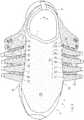
FIG.1 is a schematic plan view showing a shoe having an upper according to an embodiment of the present invention.FIG.2 is a schematic side view showing the shoe according to the embodiment as the upper is seen from the medial side.FIG.3 is a schematic side view showing the shoe according to the embodiment as the upper is seen from the lateral side.FIG.4 is an exploded perspective view showing a reinforcement member.FIG.5 is a schematic plan view showing the shoe with the shoelace removed and the reinforcement member pulled open.FIG.6 is a perspective view showing, on an enlarged scale, a medial side portion in the stationary standing (standstill) position, as seen diagonally from the front direction.FIG.7 is a perspective view, on an enlarged scale, the medial side portion when the foot is dorsiflexed, as seen diagonally from the front direction.FIG.8 is a perspective view showing, on an enlarged scale, a lateral side portion in the stationary standing position, as seen diagonally from the front direction.FIG.9 is a perspective view showing, on an enlarged scale, the lateral side portion when the foot is dorsiflexed, as seen diagonally from the front direction.FIG.10 is a schematic plan view showing the bone structure of the foot.FIG.11 is an exploded perspective view showing an alternative example of a reinforcement member.FIG.12 is a schematic side view showing an alternative example of an upper with the shoelace removed.- Preferably, the
string portions 10 are set so that thestring portions 10 are freely displaceable and/or deformable in a transverse directionX of the foot and/or in an up-down direction. That is, thestring portions 10 are in at least one or more state, of the state in which thestring portions 10 can be easily moved or deformed in the transverse directionX of the foot or the state in which thestring portions 10 can be easily moved or deformed in the up-down direction. - Note that "up-down direction" means to include the vertical direction and directions that are inclined forward or rearward and/or medially or laterally with respect to the vertical direction, and means to include the direction perpendicular to the direction in which the
string portions 10 extend. - Then, the string portions, as compared with an ordinary upper member having a planar structure, will more easily twist and will more easily exhibit a deformation of shrinking by being bent.
- Preferably, a widthW of each
string portion 10 in an up-down direction is set to be 1 mm to 15 mm. - If the width of the
string portion 10 in the up-down direction is too small, thestring portion 10 may strongly irritate the foot on the medial side surface and the lateral side surface. For such a reason, typically, the width of thestring portion 10 in the up-down direction is preferably 1 mm or more, more preferably 1.5 mm or more, and most preferably 2 mm or more. - On the other hand, if the width of the
string portion 10 in the up-down direction is too large, thestring portion 10 itself will no longer have a linear structure and will come closer to a planar structure, thereby inhibiting the free displacement and deformation of thestring portions 10. For such a reason, typically, the width of thestring portion 10 in the up-down direction is preferably 15 mm or less, more preferably 12 mm or less, and most preferably 10 mm or less. - Preferably, a widthW of each
string portion 10 in an up-down direction is set to be 2 mm to 15 mm; and
thestring portions 10 are set so that thestring portions 10 are freely displaceable and/or deformable in a transverse directionX of the foot and/or in the up-down direction. - Then, the
string portions 10 will likely displace or deform freely and the irritation on the foot will be small. - Preferably, the
string portions 10 are formed by a woven fabric or a knit fabric. - Then, it will be easy to produce flexible and non-elongatable (non-stretchable)
string portions 10. - Preferably, the woven fabric or the knit fabric includes a plurality (of strands) of non-stretchable fibers that are long (elongated) in the longitudinal directionY.
- Then, it will be even easier to produce flexible and non-elongatable (non-stretchable)
string portions 10. - Note that each
string portion 10 may include one strand or a plurality of strands of another fiber that is stretchable in the longitudinal directionY. In that case, thestring portions 10 may shrink without being bent. - Preferably, at least one of the plurality of
panels 11 or at least a part of the plurality of non-elongatable (non-stretchable)string portions 10 covers at least a portion of a ballO1 of a big toe on the medial side of the foot; and
at least another one of the plurality ofpanels 11 or at least another part of the plurality of non-elongatable (non-stretchable)string portions 10 covers at least a portion of a ballO5 of a little toe on the lateral side of the foot. - With the
string portions 10 and thepanels 11 covering the areas of the ballO1 of the big toe and the ballO5 of the little toe, a high stability will be realized in the transverse direction. - Preferably, a lengthL of each
string portion 10 between the pair ofpanels 11 that are adjacent to each other is set to be 3 to 15 mm. - If the length of the
string portions 10 is too short, the free displacement or deformation of thestring portions 10 will be inhibited. For such a reason, typically, the length of thestring portions 10 is preferably 3 mm or more, more preferably 4 mm or more, and most preferably 5 mm or more. - On the other hand, if the length of the
string portions 10 is too long, when a load in the transverse direction is applied on the foot, thestring portions 10 will exhibit a deformation of being bent outward, thereby lowering the stability. For such a reason, typically, the length of thestring portions 10 is preferably 15 mm or less, more preferably 12 mm or less, and most preferably 10 mm or less. - Preferably, in the
medial side portion 31 or thelateral side portion 32, a ratio of a widthW of thestring portion 10 with respect to a pitchP in an up-down direction at which ones of thestring portions 10 that are adjacent to each other in the up-down direction are arranged (e.g., placement of thestring portions 10 at a predetermined frequency) is set to be 50% or more and less than 100%. - If the gap between
string portions string portion 10 with respect to the pitch in the up-down direction at which thestring portions 10 that are adjacent to each other are arranged is preferably 50% or more, more preferably 55% or more, and most preferably 60% or more. - On the other hand, if the gap between the
string portions string portions 10, and the production yield of the upper may lower. For such a reason, the width ratio W/P is preferably less than 100%, more preferably 95% or less, and most preferably 90% or less. - Preferably, the upper further includes a
flexible member 33 that covers at least one side surface of the medial side surface and the lateral side surface of the foot and that is more stretchable at least in the longitudinal directionY of the foot than thestring portions 10,
wherein areinforcement member 34, formed by (including) thepanels 11 and thestring portions 10, is placed on an outer surface of theflexible member 33. - Then, the
flexible member 33 is inserted between thereinforcement member 34 and the side surface of the foot. Therefore, the pressure on the surface of the foot from thestring portions 10 or thepanels 11 will be reduced by theflexible member 33. - Preferably, the upper further includes a
flexible member 33 that covers at least one side surface of the medial side surface and the lateral side surface of the foot and that is more stretchable at least in the longitudinal directionY of the foot than thestring portions 10,
wherein areinforcement member 34, formed by (including) thepanels 11 and thestring portions 10, is placed along an outer surface of theflexible member 33, and at least thestring portions 10 are set to be unattached to the outer surface of theflexible member 33. - Then, in addition to the pressure being reduced by the
flexible member 33, thestring portions 10 in the unattached state will have a high degree of freedom of displacement and deformation. Therefore, the fitting quality will improve. - More preferably, at least an upper-half area of each
panel 11 is in contact with, while being unattached to, the outer surface of theflexible member 33 on a medial side and on a lateral side of an instep. - Then, not only the
string portions 10 but also the upper halves of thepanels 11 are in contact with, while being unattached to, the outer surface of theflexible member 33. Therefore, thepanels 11 can also be easily displaced, and the fitting quality may further improve. - Preferably, the upper includes:
- a
mesh member 1 formed by a woven fabric or a knit fabric, defining elongate slit-shaped through holesS arranged in a plurality of columns and a plurality of rows; and - at least one
panel member 2 layered on themesh member 1, with the through holesS arranged in the plurality of columns and the plurality of rows being open (not covered), - wherein the
string portions 10 are formed (defined) by body parts of themesh member 1 between those of the plurality of through holesS that are spaced apart (separated) from, and adjacent to, each other in a circumferential direction of the foot. - Then, areas of the
mesh member 1 between the through holesS define thestring portions 10, and it will be easy to produce a large number ofstring portions 10 as themesh member 1 and thepanel member 2 are layered together. - More preferably, the upper further includes:
- another
panel member 2 separate from the at least one panel member, - wherein the pair of
panel members 2 forms at least a portion of the upper, with the through holesS arranged in the plurality of columns and the plurality of rows being open (not covered), and the pair ofpanel members 2 layered together with themesh member 1 sandwiched therebetween. - Then, the
mesh member 1, sandwiched between a pair ofpanel members panel members mesh member 1 will have an improved durability. - Preferably, a flexural rigidity of the at least one
panel member 2 is set to a larger value than a flexural rigidity of themesh member 1. - By the fastening force applied to the
panels 11 from theshoelace 6, thepanel member 2 having a greater flexural rigidity than themesh member 1 will fit to the side surface on the medial side and the lateral side of the foot, thereby serving to improve the stability. - On the other hand, the
mesh member 1 having a smaller rigidity than thepanel member 2 will increase the degree of freedom of deformation and displacement of thestring portions 10, thereby serving to improve the fitting quality. - In another aspect, an upper of the present invention includes:
- a
mesh member 1 formed by a woven fabric or a knit fabric, defining a plurality of elongate slit-shaped through holesS arranged in a plurality of columns and a plurality of rows; and - at least one
panel member 2 layered on themesh member 1, with the plurality of through holesS arranged in the plurality of columns and the plurality of rows being open (not covered), and an area (each area, portions) of themesh member 1 between the through holesS adjacent to each other being exposed. - As the exposed areas of the
mesh member 1 between the through holesS are exposed with the through holesS of themesh member 1 being open, the exposed areas of the layered structure of themesh member 1 and thepanel member 2 will have a flexibility function. Thus, the fitting quality of the upper may improve. - On the other hand, layered areas where the
panel member 2 and themesh member 1 are layered together will have a greater rigidity than the exposed areas. Therefore, the layered areas may improve the stability of the upper. - Moreover, the through holesS of the
mesh member 1 and the exposed areas of themesh member 1 will reduce the weight of the upper. - Preferably, the upper further includes a
panel member 2 different from the at least onepanel member 2; and
the pair ofpanel members 2 are layered together with themesh member 1 sandwiched therebetween, with the plurality of through holesS arranged in the plurality of columns and the plurality of rows being open (not covered), and an area (each area, portions) of themesh member 1 between the through holesS adjacent to each other being exposed, thepanel members 2 forming at least a portion of the upper. - Then, the
mesh member 1, sandwiched between the pair ofpanel members panel members mesh member 1 will have an improved endurance. - If the
panel member 2 is formed by a plate material of a synthetic resin, themesh member 1 and the pair ofpanel members - Preferably, the exposed area (areas, portions) of the
mesh member 1 extends in the longitudinal directionY between ones of the through holesS that are spaced apart (separated) from, and adjacent to, each other in a circumferential direction of the foot, and forms a plurality of string-shaped non-elongatable (non-stretchable)string portions 10 that are freely displaceable and deformable in a transverse directionX of the foot or an up-down direction of the foot. - Then, the
non-elongatable string portions 10 can easily twist and exhibit a deformation of shrinking by being bent. This will improve the fitting quality. - On the other hand, the
non-elongatable string portions 10 support the foot without elongating (stretching), and this may improve the stability. - Preferably, a flexural rigidity of the at least one
panel member 2 is set to a larger value than a flexural rigidity of themesh member 1. - The
panel member 2 having a greater flexural rigidity than themesh member 1 will fit to the side surface on the medial side and the lateral side of the foot, etc., thereby serving to improve the stability. - On the other hand, the
mesh member 1 having a smaller flexural rigidity than thepanel member 2 will increase the degree of freedom of deformation and displacement of the exposed areas, thereby serving to improve the fitting quality. - Preferably, a flexural rigidity of the
panels 11 is set to a larger value than a flexural rigidity of thestring portions 10. In other words, the flexural rigidity of thestring portions 10 is smaller than the flexural rigidity of thepanels 11. Such rigidity setting will increase the degree of freedom of deformation and displacement of thestring portions 10, thereby serving to improve the fitting quality. - The present invention will be understood more clearly from the following description of preferred embodiments taken in conjunction with the accompanying drawings. Note however that the embodiments and the drawings are merely illustrative and should not be taken to define the scope of the present invention. The scope of the present invention shall be defined only by the appended claims. In the accompanying drawings, like reference numerals denote like components throughout the plurality of figures.
- Any feature illustrated and/or depicted in conjunction with one embodiment or alternative examples may be used in the same or similar form in one or more of alternative embodiments or alternative examples, and/or may be used in combination with, or in place of, any feature of the alternative embodiments.
Embodiment 1 of the present invention will now be described with reference toFIG.1 to FIG.9 .- A shoe for the left foot will be illustrated in the following description.
- The shoe shown in
FIG.1 is a shoe for sports or running, for example, and includes an upper3 secured to a sole8 shown inFIG.2 . The upper3 includes aflexible member 33, areinforcement member 34 and a shoelace (fastening member)6. - The sole8 is placed under the upper3 and is to be in contact with the road surface. The
flexible member 33 wraps the medial side surface, the lateral side surface, the toe and the heel of the foot, and is formed in the shape of a sock, for example. Thereinforcement member 34 and theshoelace 6 are for fitting theflexible member 33 to the instep. - Note that the area of the
flexible member 33 is coarsely dotted inFIG.5 . - Although the end portions of the
shoelace 6 are not shown inFIG.1 to FIG.3 , the end portions are firmly tied together after the foot is inserted in theflexible member 33. As the end portions of theshoelace 6 are tied together, theflexible member 33 fits to the foot. - As shown in
FIG.1 to FIG.3 , theflexible member 33 includes a top line (wearing opening)7 allowing the foot to be inserted to wear the shoe. The leg protrudes upward through thetop line 7 when the shoe is worn, and theshoelace 6 is placed in an area anterior to thetop line 7. - As shown in
FIG.4 , thereinforcement member 34 includes amesh member 1 and a pair ofpanel members 2. Themesh member 1 uses such a structure and material that it is less stretchable in the longitudinal directionY than thepanel members 2. On the other hand, thepanel members 2 preferably have a greater flexural rigidity than themesh member 1. The material of thepanel members 2 may be any of various materials, such as a resin part, an artificial leather, a TPU or a rubber. - Note that the flexural rigidity of the
mesh member 1 and that of thepanel members 2 may be similar to each other. - The
panel members 2 are comb-shaped, for example, including a plurality ofpanels 11 to be described later. On the other hand, themesh member 1 includes a large number ofstring portions 10 to be described later. - Note that the
mesh member 1 ofFIG.4 and thestring portions 10 ofFIG.6 are geometrically patterned. On the other hand, the area of thepanels 11 is densely dotted inFIG.5 . - The
mesh member 1 ofFIG.4 is formed by a woven fabric or a knit fabric, for example, and is more preferably formed by a woven fabric, defining a larger number of elongate slit-shaped through holesS arranged in a plurality of columns and a plurality of rows. Thepanel members 2 are layered on the front side and the back side of themesh member 1, while the through holesS arranged in the plurality of columns and the plurality of rows are open and the areas of themesh member 1 between through holesS that are adjacent to each other (hereinafter referred to as exposedportions 10A) are exposed. That is, thepanel members 2 are layered together with themesh member 1 sandwiched therebetween. - Note that the
mesh member 1 may be formed by a thin resin film (FRP) containing a reinforcement fiber extending in the longitudinal directionY. - The
reinforcement member 34 ofFIG. 1 to FIG.3 is joined with the upper surface of amidsole 80 by bonding and/or welding, for example, and includes amedial side portion 31 covering the medial side surface of the instep and alateral side portion 32 covering the lateral side surface of the instep. Themedial side portion 31 and thelateral side portion 32 of thereinforcement member 34 include a plurality ofpanels 11 and a large number ofstring portions 10. - Next, the
panels 11 and thestring portions 10 will be described in detail. Note that themedial side portion 31 and thelateral side portion 32 are similar in structure. - In the
medial side portion 31 and thelateral side portion 32, thepanels 11 are separated from each other in the longitudinal directionY of the foot, covering at least a portion of the side surface of the foot, wherein thepanels 11 are pulled by the shoelace (an example of the fastening member)6 toward acenter portion 36 between the medial side and the lateral side of the foot. That is, for example, loopsR are sewn to the upper end portions of thepanels 11 ofFIG.1 , with theshoelace 6 passed through the loopsR. - The
panels 11 ofFIG.2 andFIG.3 covering the side surface of the instep extend in the transverse directionX of the foot (FIG.1 ) and/or in the up-down direction (including an inclined up-down direction). Note that thestring portions 10 cover the side surface of the instep. - Herein, instep means a part that is posterior to the metatarsal phalangeal jointMP of
FIG.10 and anterior to the anterior endBe of the talus, and that covers the upper surface and the side surface of the foot. Note that thepanels 11 may or may not cover the toe anterior to the metatarsal phalangeal jointMP and the heel portion posterior to the anterior endBe of the talus as do theposterior panels 11 ofFIG.2 . - The
panels 11 covering the side surface of the instep are each formed in a rectangular band shape (strip shape) extending in a diagonal posterior direction or in the up-down direction toward themidsole 80 from the upper end portion thereof with which the loopR is joined. Thepanels 11 are separated from each other in the longitudinal directionY or in a diagonal longitudinal direction, with a large number ofstring portions 10 placed betweenpanels 11 that are adjacent to each other. - The slit-shaped through holesS of the
mesh member 1 ofFIG.4 extend generally in parallel to each other in a diagonal longitudinal directionY. The through holesS are regularly arranged in the diagonal longitudinal directionY and in the transverse direction. - Areas between through holesS in the longitudinal directionY are joined with the
panels 11 of thepanel members 2. Thus, each exposedarea 10A forms astring portion 10 ofFIG.3 extending in the longitudinal directionY between those through holesS that are separated from, and adjacent to, each other in the circumferential direction of the foot. - The
string portions 10 are non-elongatable (non-stretchable) in the longitudinal directionY. Suchnon-stretchable string portions 10 may be formed by the woven fabric of themesh member 1 ofFIG.4 including a plurality of strands of a non-stretchable fiber that are long in the longitudinal directionY. - Note that the
string portions 10 may be stretchable by including another fiber stretchable in the longitudinal directionY. - As shown in
FIG. 1 to FIG.3 , eachstring portion 10 is formed in a string-like form placed between a pair ofpanels 11 adjacent to each other the longitudinal directionY and extending in the longitudinal directionY. On the other hand, the widthW in the up-down direction of eachstring portion 10 ofFIG.6 is set to be about 2 mm to about 5 mm, for example, and eachstring portion 10 has a planar shape with a small area and is formed in a linear shape. Thus, thestring portions 10 are set so that thestring portions 10 are freely displaceable and/or deformable in the transverse directionX of the foot (FIG.1 ) and/or in the up-down direction. - As shown in an enlarged scale in
FIG.6 , the widthW in the up-down direction of thestring portion 10 means the distance between the upper edge and the lower edge of onestring portion 10. In other words, the widthW means the distance between a pair of intersectionsO andO at which a virtual line intersects with the two edges of onestring portion 10, wherein the virtual line extends across thestring portion 10 in the up-down direction or in a diagonal up-down direction (extends perpendicular to the direction in which thestring portion 10 extends). Note that these distances should be considered to be those along the curve of the surface of the foot. - In the
medial side portion 31 and thelateral side portion 32, the plurality ofstring portions 10 are arranged generally at a constant pitchP in the up-down direction. The ratio W/P of the widthW with respect to the pitchP of thestring portions 10 in the up-down direction is set to be about 60% to about 80%, for example. - Note that the pitchP of the
string portions 10 means the distance between the center lineCL of onestring portion 10 and the center lineCL of anotheradjacent string portion 10, with the center line extending in the extending direction of thestring portion 10. - The lengthL of the
string portions 10, i.e., the lengthL of thestring portions 10 between a pair ofpanels 11 that are adjacent to each other, is set to be about 4 to about 10 mm, for example. - Note that the preferable thickness of the
string portions 10, i.e., the thickness of themesh member 1 ofFIG.4 , will commonly be about 0.5 to about 1.5 mm. - The
flexible member 33 ofFIG.5 is formed by, for example, a foamed resin, a knit fabric, a meshed member or a combination thereof, and is more stretchable in the longitudinal directionY than thestring portions 10 and thepanels 11. As shown inFIG.1 to FIG.3 , thereinforcement member 34 including thepanels 11 and thestring portions 10 are placed on the outer surface of theflexible member 33. - The
reinforcement member 34 including thepanels 11 and thestring portions 10 is placed along the outer surface of theflexible member 33 on the medial side and on the lateral side of the instep. On the medial side and on the lateral side of the instep, the majority of thepanels 11 and thestring portions 10 are set to be unattached to the outer surface of theflexible member 33. In the illustrated example, as thestring portions 10 are set to be unattached to the outer surface of theflexible member 33, thestring portions 10 are freely displaceable and/or deformable in the transverse directionX of the foot and/or in the up-down direction. Note that it is preferred that at least an upper-half area of eachpanel 11 is in contact with, while being unattached to, the outer surface of theflexible member 33 on the medial side and on the lateral side of the instep. - On the other hand, the lower edge of the
reinforcement member 34 is attached (secured) to themidsole 80 as described above. Thereinforcement member 34 is attached (sewn) to theflexible member 33 at the rear end of the upper3. - In the present invention, "attached" may be replaced by the word "secured", and it conceptually means that objects are joined together in such a manner that they cannot be removed easily. Specifically, "attached" means that objects are joined together by means of bonding, welding or sewing, or by a combination of two or more of these means.
- In the present invention, "unattached state" means a free state in which the
panel 11 or thereinforcement member 34 is not attached to theflexible member 33. Thepanel 11 or thereinforcement member 34 in the unattached state is not bound by theflexible member 33 and will be allowed to undergo displacement or deformation such as twist or rotation about the position of attachment as the center. On the other hand, areas of theflexible member 33 where thestring portions 10 or thepanels 11 are not attached will be allowed to undergo stretching/shrinking deformation in response to deformation of the foot or the upper. - On the medial side shown in
FIG.2 , at least one of the plurality ofpanels 11 or at least a part of the plurality ofnon-stretchable string portions 10 covers at least a portion of the side surface of the ballO1 of the big toe on the medial side of the foot shown inFIG.10 . On the other hand, on the lateral side shown inFIG.3 , at least one of the plurality ofpanels 11 or at least a part of the plurality ofnon-stretchable string portions 10 covers at least a portion of the side surface of the ballO5 of the little toe on the lateral side of the foot shown inFIG.10 . - Next, the behavior of the present upper will be described. That is, the behavior of the present upper during the transition from the stationary standing position shown in
FIG.6 andFIG.8 to the dorsiflexed position ofFIG.7 andFIG.9 in which the heel is off the ground will be described. Note that "dorsiflexion of the foot" in the present embodiment means dorsiflexion of a joint within the foot (e.g., the metatarsal phalangeal joint, the interphalangeal joint, etc.). - Now, when the shoe or the foot of
FIG.7 orFIG.9 is dorsiflexed, the upper surface of the instep shrinks. - On the other hand, the
string portions 10 ofFIG.7 (andFIG.9 ), when dorsiflexed, exhibit a deformation as if it were shrunk in the direction along the upper surface of the instep. This deformation may be realized by thestring portions 10 actually shrinking, as well as by deformation of the surface of theplanar string portions 10 into a curved surface. - That is, as can be seen from a comparison between
FIG.6 andFIG.7 , thepanels 11 displace so that the distance betweenpanels 11 that are adjacent to each other shortens upon dorsiflexion. The lower end of thepanel member 2 is attached to themidsole 80. Therefore, eachpanel 11 inclines in the anterior directionYF about the position of attachment as the center. Thus, thepanels 11 and thestring portions 10 displace and deform at the same time. - On the other hand, when a force is applied in the transverse directionX of the foot in the upper3 of
FIG.1 , thepanels 11 pulled toward thecenter portion 36 by theshoelace 6 fit to, and support, the side surfaces on the medial side and the lateral side of the foot. Then, thenon-stretchable string portions 10 will resist the force, thereby reducing the movement of the ballO1 of the big toe ofFIG.10 toward the medial side and reducing the movement of the ballO5 of the little toe toward the lateral side. - Next, alternative examples will be described.
- As shown in
FIG.11 , thereinforcement member 34 may include asingle mesh member 1 layered with asingle panel member 2. - In
FIG.12 showing another alternative example, thestring portions 10 are shown in solid black. A large number ofstring members 10B may be sandwiched between thepanels 11 and theflexible member 33, thereby forming thestring portions 10 between thepanels string portions 10 are set to be unattached to theflexible member 33. - While preferred embodiments have been described above with reference to the drawings, various obvious changes and modifications will readily occur to those skilled in the art upon reading the present specification.
- For example, a lower half or a whole of each panel may be secured to the flexible member.
- The flexural rigidity of the panel member may be smaller than or similar to that of the mesh member.
- The sole placed under the upper may only include a so-called "outsole".
- The panels and the string portions may be provided only in one of the medial side portion and the lateral side portion.
- A tongue may be provided in the center portion of the upper.
- The shoelace passing holes may be eyelets instead of loops.
- A belt may be employed as the fastening member instead of, or in addition to, a shoelace.
- Thus, such changes and modifications are deemed to fall within the scope of the present invention, which is defined by the appended claims.
- The present invention is applicable to shoes for court sports and running shoes, and also to shoes of various other applications such as walking.
- 1: Mesh member 10:
String portion 10A: Exposed portion - 10B: String (Lace) member
- 2: Panel member 11: Panel
- 3: Upper 31: Medial side portion 32: Lateral side portion
33: Flexible member 34: Reinforcement member 36: Center portion - 6: Shoelace (fastening member) 7: Top line 8: Sole 80: Midsole
- L: Length P: Pitch
- R: Loop S: Through hole
- O1: Ball of big toe O5: Ball of small toe
- X: Transverse direction Y: Longitudinal direction W: Width W/P: Width ratio
Claims (15)
- An upper (3) of a shoe covering at least a portion of a foot, the upper (3) comprising:a medial side portion (31) covering a medial side surface of the foot;a lateral side portion (32) covering a lateral side surface of the foot; anda plurality of panels (11) provided in the medial side portion (31) and/or the lateral side portion (32), separated from one another in a longitudinal direction (Y) of the foot, and covering at least a portion of a side surface of the foot, wherein the panels (11) are pulled by a fastening member (6) toward a central portion (36) between a medial side and a lateral side of the foot,characterized in that the upper (3) further comprising:a plurality of string-shaped non-elongatable string portions (10) extending in the longitudinal direction (Y), the string portions (10) placed between a pair of the plurality of panels (11) that are adjacent to each other in the longitudinal direction (Y), whereina gap exists between the string portions (10) and (10) that are adjacent to each other in an up-down direction.
- The upper (3) according to claim 1, wherein the string portions (10) are set so that the string portions (10) are freely displaceable and/or deformable in a transverse direction (X) of the foot and/or in an up-down direction.
- The upper (3) according to claim 1, wherein a width (W) of each of the string portions (10) in an up-down direction is set to be 1 mm to 15 mm, preferably, wherein:a width (W) of each of the string portions (10) in an up-down direction is set to be 2 mm to 15 mm; andthe string portions (10) are set so that the string portions (10) are freely displaceable and/or deformable in a transverse direction (X) of the foot and/or in the up-down direction.
- The upper (3) according to any one of claims 1 to 3, wherein the string portions (10) are formed by a woven fabric or a knit fabric.
- The upper (3) according to claim 4, wherein the woven fabric or the knit fabric includes a plurality of non-stretchable fibers that are long in the longitudinal direction (Y).
- The upper (3) according to any one of claims 1 to 5, wherein:at least one of the plurality of panels (11) or at least a part of the plurality of non-elongatable string portions (10) covers at least a portion of a ball (O1) of a big toe on the medial side of the foot; andat least another one of the plurality of panels (11) or at least another part of the plurality of non-elongatable string portions (10) covers at least a portion of a ball (O5) of a little toe on the lateral side of the foot, preferably,wherein a length L of each of the string portions (10) between the pair of panels (11) that are adjacent to each other is set to be 3 to 15 mm.
- The upper (3) according to any one of claims 1 to 6, wherein in the medial side portion (31) or the lateral side portion (32), a ratio of a width (W) of one of the string portions (10) with respect to a pitch (P) in an up-down direction at which ones of the string portions (10) that are adjacent to each other in the up-down direction are arranged is set to be 50% or more and less than 100%.
- The upper (3) according to any one of claims 1 to 7, further comprising:a flexible member (33) that covers at least one side surface of the medial side surface and the lateral side surface of the foot and that is more easily stretchable at least in the longitudinal direction (Y) of the foot than the string portions (10),wherein a reinforcement member (34), formed by the panels (11) and the string portions (10), is placed on an outer surface of the flexible member (33).
- The upper (3) according to any one of claims 1 to 7, further comprising:a flexible member (33) that covers at least one side surface of the medial side surface and the lateral side surface of the foot and that is more easily stretchable at least in the longitudinal direction (Y) of the foot than the string portions (10),wherein a reinforcement member (34), formed by the panels (11) and the string portions (10), is placed along an outer surface of the flexible member (33), and at least the string portions (10) are set to be unattached to the outer surface of the flexible member (33), preferably,wherein at least an upper-half area of each of the panels (11) is in contact with, while being unattached to, the outer surface of the flexible member (33) on a medial side and on a lateral side of an instep.
- The upper (3) according to any one of claims 1 to 9, comprising:a mesh member (1) formed by a woven fabric or a knit fabric, defining elongate slit-shaped through holes (S) arranged in a plurality of columns and a plurality of rows; andat least one panel member (2) layered on the mesh member (1), with the through holes (S) arranged in the plurality of columns and the plurality of rows being open,wherein each of the string portions (10) is formed by a body part of the mesh member (1) between two of the plurality of through holes (S) that are spaced apart from, and adjacent to, each other in a circumferential direction of the foot, preferably, the upper (3) further comprising:another panel member (2) separate from the at least one panel member,wherein the at least one and the other panel members (2) form at least a portion of the upper (3), with the through holes (S) arranged in the plurality of columns and the plurality of rows being open, and the at least one and the other panel members (2) layered together with the mesh member (1) sandwiched therebetween.
- The upper (3) according to claim 10, wherein a flexural rigidity of the at least one panel member (2) is set to a larger value than a flexural rigidity of the mesh member (1).
- An upper (3) of a shoe covering at least a portion of a foot, the upper (3) comprising:a mesh member (1) formed by a woven fabric or a knit fabric, defining a plurality of elongate slit-shaped through holes (S) arranged in a plurality of columns and a plurality of rows; andat least one panel member (2) layered on the mesh member (1), with the plurality of through holes (S) arranged in the plurality of columns and the plurality of rows being open, and an area of the mesh member (1) between the through holes (S) adjacent to each other being exposed.
- The upper (3) according to claim 12, wherein:the upper (3) further comprises another panel member (2) different from the at least one panel member (2); andthe at least one and the other members (2) are layered together with the mesh member (1) sandwiched therebetween, with the plurality of through holes (S) arranged in the plurality of columns and the plurality of rows being open, and an area of the mesh member (1) between the through holes (S) adjacent to each other being exposed, the at least one and the other members (2) forming at least a portion of the upper (3), preferably,wherein a flexural rigidity of the at least one panel member (2) is set to a larger value than a flexural rigidity of the mesh member (1).
- The upper (3) according to claim 12 or 13, wherein the area, which exposed, of the mesh member (1) extends in the longitudinal direction (Y) between ones of the through holes (S) that are spaced apart from, and adjacent to, each other in a circumferential direction of the foot, and forms a plurality of string-shaped non-elongatable string portions (10) that are freely displaceable and deformable in a transverse direction (X) of the foot or an up-down direction of the foot, preferably,
wherein a flexural rigidity of the at least one panel member (2) is set to a larger value than a flexural rigidity of the mesh member (1). - The upper (3) according to any one of claims 1 to 9, wherein a flexural rigidity of the each of the panels (11) is set to a larger value than a flexural rigidity of each of the string portions (10).
Applications Claiming Priority (1)
| Application Number | Priority Date | Filing Date | Title |
|---|---|---|---|
| PCT/JP2014/064275WO2015181928A1 (en) | 2014-05-29 | 2014-05-29 | Shoe upper |
Publications (3)
| Publication Number | Publication Date |
|---|---|
| EP3150077A1 EP3150077A1 (en) | 2017-04-05 |
| EP3150077A4 EP3150077A4 (en) | 2017-08-09 |
| EP3150077B1true EP3150077B1 (en) | 2018-07-04 |
Family
ID=54698307
Family Applications (1)
| Application Number | Title | Priority Date | Filing Date |
|---|---|---|---|
| EP14893246.0AActiveEP3150077B1 (en) | 2014-05-29 | 2014-05-29 | Shoe upper |
Country Status (4)
| Country | Link |
|---|---|
| US (1) | US10165830B2 (en) |
| EP (1) | EP3150077B1 (en) |
| JP (1) | JP5909032B1 (en) |
| WO (1) | WO2015181928A1 (en) |
Families Citing this family (48)
| Publication number | Priority date | Publication date | Assignee | Title |
|---|---|---|---|---|
| CN103381003B (en) | 2004-10-29 | 2016-05-25 | 博技术有限公司 | Based on the closed-system of spool |
| US8468657B2 (en) | 2008-11-21 | 2013-06-25 | Boa Technology, Inc. | Reel based lacing system |
| US10070695B2 (en) | 2010-04-30 | 2018-09-11 | Boa Technology Inc. | Tightening mechanisms and applications including the same |
| US9375053B2 (en) | 2012-03-15 | 2016-06-28 | Boa Technology, Inc. | Tightening mechanisms and applications including the same |
| US9101181B2 (en) | 2011-10-13 | 2015-08-11 | Boa Technology Inc. | Reel-based lacing system |
| US9516923B2 (en) | 2012-11-02 | 2016-12-13 | Boa Technology Inc. | Coupling members for closure devices and systems |
| WO2014074645A2 (en) | 2012-11-06 | 2014-05-15 | Boa Technology Inc. | Devices and methods for adjusting the fit of footwear |
| US9439477B2 (en) | 2013-01-28 | 2016-09-13 | Boa Technology Inc. | Lace fixation assembly and system |
| WO2014124054A1 (en) | 2013-02-05 | 2014-08-14 | Boa Technology Inc. | Closure devices for medical devices and methods |
| US9610185B2 (en) | 2013-03-05 | 2017-04-04 | Boa Technology Inc. | Systems, methods, and devices for automatic closure of medical devices |
| US10251451B2 (en) | 2013-03-05 | 2019-04-09 | Boa Technology Inc. | Closure devices including incremental release mechanisms and methods therefor |
| KR20150135791A (en) | 2013-04-01 | 2015-12-03 | 보아 테크놀러지, 인크. | Methods and devices for retrofitting footwear to include a reel based closure system |
| US10076160B2 (en) | 2013-06-05 | 2018-09-18 | Boa Technology Inc. | Integrated closure device components and methods |
| EP3777595B1 (en) | 2013-06-05 | 2024-08-07 | Boa Technology Inc. | Integrated closure device components and methods |
| US9629417B2 (en) | 2013-07-02 | 2017-04-25 | Boa Technology Inc. | Tension limiting mechanisms for closure devices and methods therefor |
| EP3019043B1 (en) | 2013-07-10 | 2019-09-18 | Boa Technology Inc. | Closure devices including incremental release mechanisms and methods therefor |
| WO2015035257A2 (en) | 2013-09-05 | 2015-03-12 | Boa Technology Inc. | Alternative lacing guides for tightening mechanisms and methods therefor |
| KR102539616B1 (en) | 2013-09-13 | 2023-06-07 | 보아 테크놀러지, 인크. | Reel based closure device and method therefore |
| EP3071159B1 (en) | 2013-11-18 | 2025-07-09 | Boa Technology Inc. | Methods and devices for providing automatic closure of prosthetics and orthotics |
| USD835976S1 (en) | 2014-01-16 | 2018-12-18 | Boa Technology Inc. | Coupling member |
| US20160058127A1 (en) | 2014-08-28 | 2016-03-03 | Boa Technology Inc. | Devices and methods for enhancing the fit of boots and other footwear |
| US10575591B2 (en) | 2014-10-07 | 2020-03-03 | Boa Technology Inc. | Devices, methods, and systems for remote control of a motorized closure system |
| USD835898S1 (en) | 2015-01-16 | 2018-12-18 | Boa Technology Inc. | Footwear lace tightening reel stabilizer |
| US20160324269A1 (en)* | 2015-05-08 | 2016-11-10 | Under Armour, Inc. | Footwear Including an Adaptable and Adjustable Lacing System |
| US10004297B2 (en) | 2015-10-15 | 2018-06-26 | Boa Technology Inc. | Lacing configurations for footwear |
| JP6581941B2 (en)* | 2016-04-26 | 2019-09-25 | 美津濃株式会社 | Shoe upper and shoes using the same |
| WO2018026957A1 (en) | 2016-08-02 | 2018-02-08 | Boa Technology Inc. | Tension member guides of a lacing system |
| CN110049694A (en) | 2016-12-09 | 2019-07-23 | Boa科技股份有限公司 | Reel based closure system |
| US10543630B2 (en) | 2017-02-27 | 2020-01-28 | Boa Technology Inc. | Reel based closure system employing a friction based tension mechanism |
| US10856619B2 (en) | 2017-03-06 | 2020-12-08 | Fuerst Group, Inc. | Article of footwear having knit upper with edging |
| JP6826653B2 (en) | 2017-03-20 | 2021-02-03 | 株式会社アシックス | Shoe upper |
| US11357279B2 (en) | 2017-05-09 | 2022-06-14 | Boa Technology Inc. | Closure components for a helmet layer and methods for installing same |
| WO2018222596A1 (en)* | 2017-05-31 | 2018-12-06 | Nike Innovate C.V. | Knitted component for an article of footwear |
| CN110891448B (en)* | 2017-05-31 | 2022-09-23 | 耐克创新有限合伙公司 | Knitted parts for footwear |
| US10772384B2 (en) | 2017-07-18 | 2020-09-15 | Boa Technology Inc. | System and methods for minimizing dynamic lace movement |
| US12396520B2 (en) | 2017-07-18 | 2025-08-26 | Boa Technology Inc. | Configurations for footwear employing reel based closure systems |
| US10834998B2 (en)* | 2018-04-13 | 2020-11-17 | Wolverine Outdoors, Inc. | Footwear including a holding cage |
| JP6582109B2 (en)* | 2018-10-26 | 2019-09-25 | 美津濃株式会社 | Shoe upper and shoes using the same |
| WO2020160421A1 (en) | 2019-02-01 | 2020-08-06 | Boa Technology Inc. | Reel based closure devices for tightening a ski boot |
| US11484097B2 (en)* | 2019-04-17 | 2022-11-01 | Nike, Inc. | Footwear upper with branched forefoot straps |
| US11492228B2 (en) | 2019-05-01 | 2022-11-08 | Boa Technology Inc. | Reel based closure system |
| US12108833B2 (en)* | 2019-05-15 | 2024-10-08 | Red Wing Shoe Company, Inc. | Pull-on boot |
| US11129445B1 (en)* | 2020-03-26 | 2021-09-28 | Nike, Inc. | Lacing systems and methods of manufacturing the same |
| JP7357775B2 (en)* | 2020-04-23 | 2023-10-06 | 株式会社アシックス | footwear |
| USD950227S1 (en)* | 2020-10-22 | 2022-05-03 | Nike, Inc. | Shoe |
| EP4265143B1 (en)* | 2021-01-21 | 2025-08-06 | ASICS Corporation | Upper and shoe comprising same |
| JP7579827B2 (en)* | 2021-07-01 | 2024-11-08 | アクシュネット カンパニー | Golf shoes with lace fastening system for closure and comfortable fit |
| CH720738B1 (en)* | 2023-04-27 | 2025-09-30 | X Tech Swiss Gmbh | Sports shoe and method for manufacturing |
Family Cites Families (31)
| Publication number | Priority date | Publication date | Assignee | Title |
|---|---|---|---|---|
| US2147197A (en)* | 1936-11-25 | 1939-02-14 | Hood Rubber Co Inc | Article of footwear |
| US4817303A (en)* | 1987-07-17 | 1989-04-04 | Avia Group International, Inc. | Athletic shoe having a dual side lacing system |
| US5377430A (en)* | 1993-09-17 | 1995-01-03 | Nike, Inc. | Shoe with elastic closure system |
| JP2004313443A (en) | 2003-04-16 | 2004-11-11 | Asics Corp | Shoe shape selection method, shoe shape selection system and shoe tip shape selection method |
| AU2004231386C1 (en) | 2003-04-24 | 2007-02-08 | Asics Corporation | Sports shoes having upper part with improved fitting property |
| USD518283S1 (en) | 2003-07-18 | 2006-04-04 | Asics Corporation | Shoe upper |
| USD527516S1 (en) | 2003-07-18 | 2006-09-05 | Asics Corporation | Portion of a shoe upper |
| US6990755B2 (en) | 2003-10-09 | 2006-01-31 | Nike, Inc. | Article of footwear with a stretchable upper and an articulated sole structure |
| US7293371B2 (en)* | 2004-09-22 | 2007-11-13 | Nike, Inc. | Woven shoe with integral lace loops |
| US7836608B2 (en)* | 2004-12-06 | 2010-11-23 | Nike, Inc. | Article of footwear formed of multiple links |
| US20070199210A1 (en)* | 2006-02-24 | 2007-08-30 | The Timberland Company | Compression molded footwear and methods of manufacture |
| US7870681B2 (en)* | 2006-05-25 | 2011-01-18 | Nike, Inc. | Article of footwear having an upper with thread structural elements |
| US7574818B2 (en)* | 2006-05-25 | 2009-08-18 | Nike, Inc. | Article of footwear having an upper with thread structural elements |
| US8312645B2 (en) | 2006-05-25 | 2012-11-20 | Nike, Inc. | Material elements incorporating tensile strands |
| US7546698B2 (en) | 2006-05-25 | 2009-06-16 | Nike, Inc. | Article of footwear having an upper with thread structural elements |
| DE202006009950U1 (en) | 2006-06-26 | 2007-11-08 | Puma Aktiengesellschaft Rudolf Dassler Sport | Shoe, in particular sports shoe |
| EP2078468B1 (en) | 2006-10-19 | 2017-02-08 | ASICS Corporation | Sports shoe having upper portion with improved fitness |
| US8225530B2 (en)* | 2006-11-10 | 2012-07-24 | Nike, Inc. | Article of footwear having a flat knit upper construction or other upper construction |
| US8008599B2 (en)* | 2007-07-09 | 2011-08-30 | Nike, Inc. | Method for manufacturing layered elements with incisions |
| US8037621B2 (en)* | 2007-09-13 | 2011-10-18 | Nike, Inc. | Article of footwear including a woven strap system |
| DE102009028627B4 (en)* | 2009-08-18 | 2019-12-19 | Adidas Ag | Sports Shoe |
| US8266827B2 (en) | 2009-08-24 | 2012-09-18 | Nike, Inc. | Article of footwear incorporating tensile strands and securing strands |
| WO2011129017A1 (en) | 2010-04-16 | 2011-10-20 | 株式会社アシックス | Structure for forefoot section of shoe upper part |
| US8578632B2 (en)* | 2010-07-19 | 2013-11-12 | Nike, Inc. | Decoupled foot stabilizer system |
| US9282787B2 (en)* | 2011-06-10 | 2016-03-15 | Crocs, Inc. | Molded footwear with woven appearance and ventilation features |
| US9038288B2 (en) | 2011-09-26 | 2015-05-26 | Nike, Inc. | Athletic footwear with ball control portions |
| EP2912962B1 (en) | 2012-10-24 | 2020-01-01 | ASICS Corporation | Upper provided with sponge member in heel part |
| JP5442170B1 (en)* | 2013-01-24 | 2014-03-12 | 株式会社アシックス | Shoes and manufacturing method thereof |
| US9826799B2 (en)* | 2013-03-14 | 2017-11-28 | Nike, Inc. | Uppers and articles incorporating same |
| US9301567B2 (en)* | 2014-08-29 | 2016-04-05 | Nike, Inc. | Article of footwear incorporating a knitted component with monofilament areas |
| DE102014220087B4 (en)* | 2014-10-02 | 2016-05-12 | Adidas Ag | Flat knitted shoe top for sports shoes |
- 2014
- 2014-05-29EPEP14893246.0Apatent/EP3150077B1/enactiveActive
- 2014-05-29WOPCT/JP2014/064275patent/WO2015181928A1/enactiveApplication Filing
- 2014-05-29JPJP2015556885Apatent/JP5909032B1/enactiveActive
- 2014-05-29USUS15/313,371patent/US10165830B2/enactiveActive
Non-Patent Citations (1)
| Title |
|---|
| None* |
Also Published As
| Publication number | Publication date |
|---|---|
| JP5909032B1 (en) | 2016-04-26 |
| US20170215523A1 (en) | 2017-08-03 |
| EP3150077A4 (en) | 2017-08-09 |
| JPWO2015181928A1 (en) | 2017-04-20 |
| US10165830B2 (en) | 2019-01-01 |
| EP3150077A1 (en) | 2017-04-05 |
| WO2015181928A1 (en) | 2015-12-03 |
Similar Documents
| Publication | Publication Date | Title |
|---|---|---|
| EP3150077B1 (en) | Shoe upper | |
| US12127628B2 (en) | Article of footwear with multiple durometer outsole | |
| US20210177070A1 (en) | Method including footwear and sock having aligning indicia | |
| US8713821B2 (en) | Athletic shoes having an upper whose fitting property is improved | |
| EP2559352B1 (en) | Structure for forefoot section of shoe upper part | |
| JP6473201B1 (en) | shoes | |
| US20110252666A1 (en) | Footwear with expandable entry and exit feature | |
| CN104379014A (en) | Sole structure configured to allow relative heel/forefoot motion | |
| JP2016209565A (en) | Adjustable shoe upper and adjustable sole | |
| EP3130247B1 (en) | Shoe upper | |
| CN114080166B (en) | Running shoes with self-adapting vamp material | |
| EP3954244A1 (en) | Shoe | |
| US20170251762A1 (en) | Footwear Upper With Ribbed Panels | |
| CA2804472A1 (en) | Shoe | |
| JP4351199B2 (en) | Athletic shoes with improved upper fit | |
| JP2005329270A6 (en) | Athletic shoes with improved upper fit | |
| CN100411559C (en) | The sneakers which improved the comfort of the upper | |
| US10212989B2 (en) | Shoe having upper and sole | |
| US20250248486A1 (en) | Cage lacing footwear |
Legal Events
| Date | Code | Title | Description |
|---|---|---|---|
| STAA | Information on the status of an ep patent application or granted ep patent | Free format text:STATUS: THE INTERNATIONAL PUBLICATION HAS BEEN MADE | |
| PUAI | Public reference made under article 153(3) epc to a published international application that has entered the european phase | Free format text:ORIGINAL CODE: 0009012 | |
| STAA | Information on the status of an ep patent application or granted ep patent | Free format text:STATUS: REQUEST FOR EXAMINATION WAS MADE | |
| 17P | Request for examination filed | Effective date:20161130 | |
| AK | Designated contracting states | Kind code of ref document:A1 Designated state(s):AL AT BE BG CH CY CZ DE DK EE ES FI FR GB GR HR HU IE IS IT LI LT LU LV MC MK MT NL NO PL PT RO RS SE SI SK SM TR | |
| AX | Request for extension of the european patent | Extension state:BA ME | |
| A4 | Supplementary search report drawn up and despatched | Effective date:20170710 | |
| RIC1 | Information provided on ipc code assigned before grant | Ipc:A43B 23/02 20060101AFI20170704BHEP Ipc:A43C 1/04 20060101ALI20170704BHEP Ipc:A43B 1/04 20060101ALI20170704BHEP | |
| DAX | Request for extension of the european patent (deleted) | ||
| REG | Reference to a national code | Ref country code:DE Ref legal event code:R079 Ref document number:602014028121 Country of ref document:DE Free format text:PREVIOUS MAIN CLASS: A43B0023020000 Ipc:A43B0005060000 | |
| GRAP | Despatch of communication of intention to grant a patent | Free format text:ORIGINAL CODE: EPIDOSNIGR1 | |
| STAA | Information on the status of an ep patent application or granted ep patent | Free format text:STATUS: GRANT OF PATENT IS INTENDED | |
| RIC1 | Information provided on ipc code assigned before grant | Ipc:A43B 1/04 20060101ALI20180126BHEP Ipc:A43B 5/06 20060101AFI20180126BHEP Ipc:A43C 1/04 20060101ALI20180126BHEP Ipc:A43B 23/02 20060101ALI20180126BHEP | |
| INTG | Intention to grant announced | Effective date:20180214 | |
| RIN1 | Information on inventor provided before grant (corrected) | Inventor name:FUJITA, YOSHINORI Inventor name:FUJITA, HISANORI Inventor name:TAKASHIMA, SHINGO Inventor name:NISHIWAKI, TSUYOSHI | |
| GRAJ | Information related to disapproval of communication of intention to grant by the applicant or resumption of examination proceedings by the epo deleted | Free format text:ORIGINAL CODE: EPIDOSDIGR1 | |
| STAA | Information on the status of an ep patent application or granted ep patent | Free format text:STATUS: REQUEST FOR EXAMINATION WAS MADE | |
| GRAS | Grant fee paid | Free format text:ORIGINAL CODE: EPIDOSNIGR3 | |
| STAA | Information on the status of an ep patent application or granted ep patent | Free format text:STATUS: GRANT OF PATENT IS INTENDED | |
| GRAP | Despatch of communication of intention to grant a patent | Free format text:ORIGINAL CODE: EPIDOSNIGR1 | |
| INTC | Intention to grant announced (deleted) | ||
| GRAA | (expected) grant | Free format text:ORIGINAL CODE: 0009210 | |
| STAA | Information on the status of an ep patent application or granted ep patent | Free format text:STATUS: THE PATENT HAS BEEN GRANTED | |
| INTG | Intention to grant announced | Effective date:20180514 | |
| AK | Designated contracting states | Kind code of ref document:B1 Designated state(s):AL AT BE BG CH CY CZ DE DK EE ES FI FR GB GR HR HU IE IS IT LI LT LU LV MC MK MT NL NO PL PT RO RS SE SI SK SM TR | |
| REG | Reference to a national code | Ref country code:GB Ref legal event code:FG4D | |
| REG | Reference to a national code | Ref country code:CH Ref legal event code:EP | |
| REG | Reference to a national code | Ref country code:AT Ref legal event code:REF Ref document number:1013571 Country of ref document:AT Kind code of ref document:T Effective date:20180715 | |
| REG | Reference to a national code | Ref country code:IE Ref legal event code:FG4D | |
| REG | Reference to a national code | Ref country code:DE Ref legal event code:R096 Ref document number:602014028121 Country of ref document:DE | |
| REG | Reference to a national code | Ref country code:NL Ref legal event code:MP Effective date:20180704 | |
| REG | Reference to a national code | Ref country code:LT Ref legal event code:MG4D | |
| REG | Reference to a national code | Ref country code:AT Ref legal event code:MK05 Ref document number:1013571 Country of ref document:AT Kind code of ref document:T Effective date:20180704 | |
| PG25 | Lapsed in a contracting state [announced via postgrant information from national office to epo] | Ref country code:NL Free format text:LAPSE BECAUSE OF FAILURE TO SUBMIT A TRANSLATION OF THE DESCRIPTION OR TO PAY THE FEE WITHIN THE PRESCRIBED TIME-LIMIT Effective date:20180704 | |
| PG25 | Lapsed in a contracting state [announced via postgrant information from national office to epo] | Ref country code:CZ Free format text:LAPSE BECAUSE OF FAILURE TO SUBMIT A TRANSLATION OF THE DESCRIPTION OR TO PAY THE FEE WITHIN THE PRESCRIBED TIME-LIMIT Effective date:20180704 Ref country code:FI Free format text:LAPSE BECAUSE OF FAILURE TO SUBMIT A TRANSLATION OF THE DESCRIPTION OR TO PAY THE FEE WITHIN THE PRESCRIBED TIME-LIMIT Effective date:20180704 Ref country code:PL Free format text:LAPSE BECAUSE OF FAILURE TO SUBMIT A TRANSLATION OF THE DESCRIPTION OR TO PAY THE FEE WITHIN THE PRESCRIBED TIME-LIMIT Effective date:20180704 Ref country code:NO Free format text:LAPSE BECAUSE OF FAILURE TO SUBMIT A TRANSLATION OF THE DESCRIPTION OR TO PAY THE FEE WITHIN THE PRESCRIBED TIME-LIMIT Effective date:20181004 Ref country code:SE Free format text:LAPSE BECAUSE OF FAILURE TO SUBMIT A TRANSLATION OF THE DESCRIPTION OR TO PAY THE FEE WITHIN THE PRESCRIBED TIME-LIMIT Effective date:20180704 Ref country code:BG Free format text:LAPSE BECAUSE OF FAILURE TO SUBMIT A TRANSLATION OF THE DESCRIPTION OR TO PAY THE FEE WITHIN THE PRESCRIBED TIME-LIMIT Effective date:20181004 Ref country code:GR Free format text:LAPSE BECAUSE OF FAILURE TO SUBMIT A TRANSLATION OF THE DESCRIPTION OR TO PAY THE FEE WITHIN THE PRESCRIBED TIME-LIMIT Effective date:20181005 Ref country code:RS Free format text:LAPSE BECAUSE OF FAILURE TO SUBMIT A TRANSLATION OF THE DESCRIPTION OR TO PAY THE FEE WITHIN THE PRESCRIBED TIME-LIMIT Effective date:20180704 Ref country code:LT Free format text:LAPSE BECAUSE OF FAILURE TO SUBMIT A TRANSLATION OF THE DESCRIPTION OR TO PAY THE FEE WITHIN THE PRESCRIBED TIME-LIMIT Effective date:20180704 Ref country code:IS Free format text:LAPSE BECAUSE OF FAILURE TO SUBMIT A TRANSLATION OF THE DESCRIPTION OR TO PAY THE FEE WITHIN THE PRESCRIBED TIME-LIMIT Effective date:20181104 Ref country code:AT Free format text:LAPSE BECAUSE OF FAILURE TO SUBMIT A TRANSLATION OF THE DESCRIPTION OR TO PAY THE FEE WITHIN THE PRESCRIBED TIME-LIMIT Effective date:20180704 | |
| PG25 | Lapsed in a contracting state [announced via postgrant information from national office to epo] | Ref country code:HR Free format text:LAPSE BECAUSE OF FAILURE TO SUBMIT A TRANSLATION OF THE DESCRIPTION OR TO PAY THE FEE WITHIN THE PRESCRIBED TIME-LIMIT Effective date:20180704 Ref country code:ES Free format text:LAPSE BECAUSE OF FAILURE TO SUBMIT A TRANSLATION OF THE DESCRIPTION OR TO PAY THE FEE WITHIN THE PRESCRIBED TIME-LIMIT Effective date:20180704 Ref country code:AL Free format text:LAPSE BECAUSE OF FAILURE TO SUBMIT A TRANSLATION OF THE DESCRIPTION OR TO PAY THE FEE WITHIN THE PRESCRIBED TIME-LIMIT Effective date:20180704 Ref country code:LV Free format text:LAPSE BECAUSE OF FAILURE TO SUBMIT A TRANSLATION OF THE DESCRIPTION OR TO PAY THE FEE WITHIN THE PRESCRIBED TIME-LIMIT Effective date:20180704 | |
| REG | Reference to a national code | Ref country code:DE Ref legal event code:R097 Ref document number:602014028121 Country of ref document:DE | |
| PG25 | Lapsed in a contracting state [announced via postgrant information from national office to epo] | Ref country code:RO Free format text:LAPSE BECAUSE OF FAILURE TO SUBMIT A TRANSLATION OF THE DESCRIPTION OR TO PAY THE FEE WITHIN THE PRESCRIBED TIME-LIMIT Effective date:20180704 Ref country code:EE Free format text:LAPSE BECAUSE OF FAILURE TO SUBMIT A TRANSLATION OF THE DESCRIPTION OR TO PAY THE FEE WITHIN THE PRESCRIBED TIME-LIMIT Effective date:20180704 Ref country code:IT Free format text:LAPSE BECAUSE OF FAILURE TO SUBMIT A TRANSLATION OF THE DESCRIPTION OR TO PAY THE FEE WITHIN THE PRESCRIBED TIME-LIMIT Effective date:20180704 | |
| PLBE | No opposition filed within time limit | Free format text:ORIGINAL CODE: 0009261 | |
| STAA | Information on the status of an ep patent application or granted ep patent | Free format text:STATUS: NO OPPOSITION FILED WITHIN TIME LIMIT | |
| PG25 | Lapsed in a contracting state [announced via postgrant information from national office to epo] | Ref country code:DK Free format text:LAPSE BECAUSE OF FAILURE TO SUBMIT A TRANSLATION OF THE DESCRIPTION OR TO PAY THE FEE WITHIN THE PRESCRIBED TIME-LIMIT Effective date:20180704 Ref country code:SK Free format text:LAPSE BECAUSE OF FAILURE TO SUBMIT A TRANSLATION OF THE DESCRIPTION OR TO PAY THE FEE WITHIN THE PRESCRIBED TIME-LIMIT Effective date:20180704 Ref country code:SM Free format text:LAPSE BECAUSE OF FAILURE TO SUBMIT A TRANSLATION OF THE DESCRIPTION OR TO PAY THE FEE WITHIN THE PRESCRIBED TIME-LIMIT Effective date:20180704 | |
| 26N | No opposition filed | Effective date:20190405 | |
| PG25 | Lapsed in a contracting state [announced via postgrant information from national office to epo] | Ref country code:SI Free format text:LAPSE BECAUSE OF FAILURE TO SUBMIT A TRANSLATION OF THE DESCRIPTION OR TO PAY THE FEE WITHIN THE PRESCRIBED TIME-LIMIT Effective date:20180704 | |
| REG | Reference to a national code | Ref country code:CH Ref legal event code:PL | |
| PG25 | Lapsed in a contracting state [announced via postgrant information from national office to epo] | Ref country code:CH Free format text:LAPSE BECAUSE OF NON-PAYMENT OF DUE FEES Effective date:20190531 Ref country code:LI Free format text:LAPSE BECAUSE OF NON-PAYMENT OF DUE FEES Effective date:20190531 Ref country code:MC Free format text:LAPSE BECAUSE OF FAILURE TO SUBMIT A TRANSLATION OF THE DESCRIPTION OR TO PAY THE FEE WITHIN THE PRESCRIBED TIME-LIMIT Effective date:20180704 | |
| REG | Reference to a national code | Ref country code:BE Ref legal event code:MM Effective date:20190531 | |
| PG25 | Lapsed in a contracting state [announced via postgrant information from national office to epo] | Ref country code:LU Free format text:LAPSE BECAUSE OF NON-PAYMENT OF DUE FEES Effective date:20190529 | |
| PG25 | Lapsed in a contracting state [announced via postgrant information from national office to epo] | Ref country code:TR Free format text:LAPSE BECAUSE OF FAILURE TO SUBMIT A TRANSLATION OF THE DESCRIPTION OR TO PAY THE FEE WITHIN THE PRESCRIBED TIME-LIMIT Effective date:20180704 | |
| PG25 | Lapsed in a contracting state [announced via postgrant information from national office to epo] | Ref country code:IE Free format text:LAPSE BECAUSE OF NON-PAYMENT OF DUE FEES Effective date:20190529 | |
| PG25 | Lapsed in a contracting state [announced via postgrant information from national office to epo] | Ref country code:BE Free format text:LAPSE BECAUSE OF NON-PAYMENT OF DUE FEES Effective date:20190531 | |
| PG25 | Lapsed in a contracting state [announced via postgrant information from national office to epo] | Ref country code:PT Free format text:LAPSE BECAUSE OF FAILURE TO SUBMIT A TRANSLATION OF THE DESCRIPTION OR TO PAY THE FEE WITHIN THE PRESCRIBED TIME-LIMIT Effective date:20181104 Ref country code:FR Free format text:LAPSE BECAUSE OF NON-PAYMENT OF DUE FEES Effective date:20190531 | |
| PG25 | Lapsed in a contracting state [announced via postgrant information from national office to epo] | Ref country code:CY Free format text:LAPSE BECAUSE OF FAILURE TO SUBMIT A TRANSLATION OF THE DESCRIPTION OR TO PAY THE FEE WITHIN THE PRESCRIBED TIME-LIMIT Effective date:20180704 | |
| PG25 | Lapsed in a contracting state [announced via postgrant information from national office to epo] | Ref country code:MT Free format text:LAPSE BECAUSE OF FAILURE TO SUBMIT A TRANSLATION OF THE DESCRIPTION OR TO PAY THE FEE WITHIN THE PRESCRIBED TIME-LIMIT Effective date:20180704 Ref country code:HU Free format text:LAPSE BECAUSE OF FAILURE TO SUBMIT A TRANSLATION OF THE DESCRIPTION OR TO PAY THE FEE WITHIN THE PRESCRIBED TIME-LIMIT; INVALID AB INITIO Effective date:20140529 | |
| PG25 | Lapsed in a contracting state [announced via postgrant information from national office to epo] | Ref country code:MK Free format text:LAPSE BECAUSE OF FAILURE TO SUBMIT A TRANSLATION OF THE DESCRIPTION OR TO PAY THE FEE WITHIN THE PRESCRIBED TIME-LIMIT Effective date:20180704 | |
| PGFP | Annual fee paid to national office [announced via postgrant information from national office to epo] | Ref country code:DE Payment date:20250402 Year of fee payment:12 | |
| PGFP | Annual fee paid to national office [announced via postgrant information from national office to epo] | Ref country code:GB Payment date:20250401 Year of fee payment:12 |