EP3147910B1 - A vehicular inspection system for inspecting a secondary side of a steam generator - Google Patents
A vehicular inspection system for inspecting a secondary side of a steam generatorDownload PDFInfo
- Publication number
- EP3147910B1 EP3147910B1EP16175434.6AEP16175434AEP3147910B1EP 3147910 B1EP3147910 B1EP 3147910B1EP 16175434 AEP16175434 AEP 16175434AEP 3147910 B1EP3147910 B1EP 3147910B1
- Authority
- EP
- European Patent Office
- Prior art keywords
- inspection vehicle
- inspection
- steam generator
- rover
- bundle
- Prior art date
- Legal status (The legal status is an assumption and is not a legal conclusion. Google has not performed a legal analysis and makes no representation as to the accuracy of the status listed.)
- Active
Links
Images


Classifications
- G—PHYSICS
- G21—NUCLEAR PHYSICS; NUCLEAR ENGINEERING
- G21C—NUCLEAR REACTORS
- G21C17/00—Monitoring; Testing ; Maintaining
- G21C17/003—Remote inspection of vessels, e.g. pressure vessels
- G21C17/013—Inspection vehicles
- B—PERFORMING OPERATIONS; TRANSPORTING
- B62—LAND VEHICLES FOR TRAVELLING OTHERWISE THAN ON RAILS
- B62D—MOTOR VEHICLES; TRAILERS
- B62D55/00—Endless track vehicles
- F—MECHANICAL ENGINEERING; LIGHTING; HEATING; WEAPONS; BLASTING
- F22—STEAM GENERATION
- F22B—METHODS OF STEAM GENERATION; STEAM BOILERS
- F22B37/00—Component parts or details of steam boilers
- F22B37/002—Component parts or details of steam boilers specially adapted for nuclear steam generators, e.g. maintenance, repairing or inspecting equipment not otherwise provided for
- Y—GENERAL TAGGING OF NEW TECHNOLOGICAL DEVELOPMENTS; GENERAL TAGGING OF CROSS-SECTIONAL TECHNOLOGIES SPANNING OVER SEVERAL SECTIONS OF THE IPC; TECHNICAL SUBJECTS COVERED BY FORMER USPC CROSS-REFERENCE ART COLLECTIONS [XRACs] AND DIGESTS
- Y02—TECHNOLOGIES OR APPLICATIONS FOR MITIGATION OR ADAPTATION AGAINST CLIMATE CHANGE
- Y02E—REDUCTION OF GREENHOUSE GAS [GHG] EMISSIONS, RELATED TO ENERGY GENERATION, TRANSMISSION OR DISTRIBUTION
- Y02E30/00—Energy generation of nuclear origin
- Y02E30/30—Nuclear fission reactors
- Y—GENERAL TAGGING OF NEW TECHNOLOGICAL DEVELOPMENTS; GENERAL TAGGING OF CROSS-SECTIONAL TECHNOLOGIES SPANNING OVER SEVERAL SECTIONS OF THE IPC; TECHNICAL SUBJECTS COVERED BY FORMER USPC CROSS-REFERENCE ART COLLECTIONS [XRACs] AND DIGESTS
- Y02—TECHNOLOGIES OR APPLICATIONS FOR MITIGATION OR ADAPTATION AGAINST CLIMATE CHANGE
- Y02P—CLIMATE CHANGE MITIGATION TECHNOLOGIES IN THE PRODUCTION OR PROCESSING OF GOODS
- Y02P80/00—Climate change mitigation technologies for sector-wide applications
- Y02P80/10—Efficient use of energy, e.g. using compressed air or pressurized fluid as energy carrier
- Y02P80/15—On-site combined power, heat or cool generation or distribution, e.g. combined heat and power [CHP] supply
- Y—GENERAL TAGGING OF NEW TECHNOLOGICAL DEVELOPMENTS; GENERAL TAGGING OF CROSS-SECTIONAL TECHNOLOGIES SPANNING OVER SEVERAL SECTIONS OF THE IPC; TECHNICAL SUBJECTS COVERED BY FORMER USPC CROSS-REFERENCE ART COLLECTIONS [XRACs] AND DIGESTS
- Y10—TECHNICAL SUBJECTS COVERED BY FORMER USPC
- Y10S—TECHNICAL SUBJECTS COVERED BY FORMER USPC CROSS-REFERENCE ART COLLECTIONS [XRACs] AND DIGESTS
- Y10S901/00—Robots
- Y10S901/01—Mobile robot
Definitions
- the present inventionrelates to the field of inspection devices generally, and more specifically to power plant steam generator inspection devices, and still more specifically to nuclear power plant steam generator inspection devices.
- a nuclear reactor vesselIn a nuclear reactor power plant, a nuclear reactor vessel is used to generate heat for the production of steam and electricity.
- the reactor vesselis typically a pressurized vessel enclosing a core of nuclear fuel and cooling water.
- Such nuclear power plantstypically contain three major components: a reactor vessel containing fuel which produces superheated water for transport to one or more steam generators, which output steam to drive a multistage steam turbine to generate electric power.
- the superheated wateris transported to the steam generator by pipes. These pipes feed the water into numerous tubes within the steam generator. These tubes are U-shaped, feeding the water back to the pipes at the outlet of the steam generator to be re-circulated back to the reactor.
- the tubes in a nuclear steam generatortypically form an inverted "U" separated by a lane, and held together by a plurality of support plates, separated at periodic vertical intervals. The height of each tube row may exceed 9.8 meters (32 feet). Six to eight or more support plates are used, each separated vertically at 0.9 to 1.8 meter (3 to 6 foot) intervals.
- the tube carrying the superheated waterare quenched with cool water, which generates the steam which drives the turbine to produce electricity.
- Tubestypically extend through support plates at quatrefoil holes. These openings provide flow through features to improve water flow in the generator and to reduce the build-up of sediment at the support plates. Nevertheless, the small areas where the quatrefoil opening must contact the tube results in areas of material build-up on the tubes, or even adherence of material being "plated out” on the tubes. This material will contribute to premature corrosion of the tubes. With known inspection devices, this condition will go undetected on all but the tubes bordering the lane.
- Insertion holesalso known as hand holes
- Flow distribution baffles within the generatoroften obstruct any room to maneuver equipment within the generator. Inspection within steam generators at elevations as high as nine meters (thirty feet) or more provide significant engineering challenges.
- the flow slots between tube rowsare often less than two inches wide and tube separation gap dimensions are often less than 2.5 cm (one inch), down to 0.76 cm (0.30 inches).
- an inspection system to inspect a secondary side of a steam generatorincludes all features of independent claim 1.
- a method of inspecting a secondary side of a steam generatorincludes all features of independent claim 8.
- FIGS. 1-9show various aspects of a vertical deployment system (VDS) 100 generally corresponding in structure to the device for inspecting the interior of steam generators disclosed in U.S. Patent No. 6,145,583, issued on November 14, 2000, to Gay et al. , which device is configured to visually inspect steam generator tubes, including upper portions of steam generator tubes, tops and bottoms of support plates, wrapper-to-support plate welds, and other steam generator internal structures.
- VDSvertical deployment system
- the VDS 100is designed for a vertical lift of instruments, sensors, tools and/or payloads about 9-10 meters (30-33 feet) or more, depending on the structure of the particular type of steam generator to be inspected.
- the steam generator representedis the FRAMATOME model 68/19, but the VDS may be utilized in other steam generators such as, but not limited to the Westinghouse Model F steam generator and other steam generators.
- the VDS 100is deployable on steam generator models having the Flow Distribution Baffle (FDB) 275 (see FIG. 3 ) on center or below the hand hole access which have at a minimum a 102 mm (4") diameter clear access into the steam generator.
- FDBFlow Distribution Baffle
- a deployable supportmay be utilized in combination with the rail assembly 110 to provide a support to another steam generator component or surface.
- the rail assemblymay be simply connected to the access port 205 such that the rail assembly is cantilevered within the steam generator.
- the steam generator support plates 225must also contain flow holes in the approximate dimension of about 89 mm (3.5") in diameter or equivalent in width for a rectangular cut out, or larger.
- the VDS 100comprises two main structural components, a rail assembly 110 (e.g., a "first boom") and a telescoping boom assembly 120 (e.g., "second boom”).
- the telescoping boom assembly 120comprises a hydraulically-actuated stacked cylinder set and, at a distal end, a delivery capsule 130, described below.
- the rail assembly 110 of the VDS 100is disposed through an access port 205 of the steam generator 200 wall and is attached to an access port flange (not shown) by an access port mounting plate (not shown).
- the rail assembly 110When the rail assembly 110 is attached, at a proximal end, to the access port 110, the rail assembly provides a stabilization leg that provides system stability for deployment of the telescoping boom assembly 120, such as is shown in U.S. Pat. No. 5,265,129 , U.S. Pat. No. 5,504,788 , and U.S. Pat. No. 6,145,583 .
- the rail assembly 110attaches, at a distal end, to the telescoping boom assembly 120 at a pivot clamp 135 that can be manually actuated or actuated via a conventional actuating device, such as a rotary actuator or a linear actuator.
- a conventional actuating devicesuch as a rotary actuator or a linear actuator.
- a rack drive servo motorattaches to the access port mounting plate and a manual crank handle 140 drives a linkage (e.g., gear(s) or gear(s) and rod(s)) attached at a distal end to the pivot clamp 135, which is secured to the telescoping boom assembly 120.
- a linkagee.g., gear(s) or gear(s) and rod(s) attached at a distal end to the pivot clamp 135, which is secured to the telescoping boom assembly 120.
- the manual crank handle 140is operatable to both deploy the telescoping boom 120 and to retract the telescoping boom to the retracted position for extraction of the VDS 100.
- one or more actuatorse.g., linear actuator(s), rotary actuator(s), or combination thereof, etc. could alternatively be used. As is shown in FIG.
- the retracted or folded VDSis extended horizontally into the steam generator through the flanged access port and through the steam generator wrapper 201.
- the telescoping boom assembly 120is aligned to be substantially parallel with the rail assembly 110 to facilitate insertion through the access port 205.
- the VDS 100is disposed initially near the base of the steam generator 200 in the tube lane, the narrow area created by the innermost inverted U-tubes 210, and more specifically through the "no-tube lane" thereof, as is shown in FIG. 3 .
- the VDS 100 systemis about 229 cm (90") long, 10 cm (4") high, and 10 cm (4") wide. This length can be adjusted to a greater or lesser length during the installation process via insertable and removable section if the plant geometry and drawback requirements dictate.
- FIG. 3shows the telescoping boom assembly 120 and delivery capsule 130 borne thereby is raised to a vertical position in the tube lane to a height of about 76 cm (30"), and extended via actuation of the telescoping boom assembly 120 stacked cylinder set, through a flow slot 220 in the support plates 225 of the steam generator, as is shown in FIG. 4 .
- FIG. 5shows continued extension of the telescoping boom assembly 120 and delivery capsule 130 borne to successively higher flow slots 220 in higher support plates 225, as is further shown in FIG. 6 .
- a camera 134is provided at a top portion of the delivery capsule 130 and may comprise a fixed camera or, as is shown in FIG. 2b , a pan, tilt and/or zoom camera.
- the delivery capsule 130itself may be fixed to a distal end of telescoping boom assembly 120 or may alternatively be rotatably attached thereto with an associated drive system (e.g., motor, rotary actuator, etc.) to rotate the delivery capsule 130 through a selected range.
- the camera 134enhances the operator's ability to navigate the delivery capsule 130 vertically through the flow slots 220 and, for the pan, tilt and/or zoom embodiment, provides additional visual inspection capability as well.
- FIG. 7shows the delivery capsule 130 extending through an inner flow slot 220 above a steam generator 200 support plate 225.
- the rail assembly 110is configured to be moved in or out of the steam generator 200 to align the telescoping boom assembly 120 with a desired one of the flow slots along the support plates 225.
- the rail assembly 110may be moved back and forth slightly or jogged to facilitate vertical movement of the telescoping boom assembly 120 so as to keep the delivery capsule 130 aligned with the flow slot 220 in each support plate 225.
- the telescoping boom assembly 120is able to extend telescopically to any desired vertical position in the steam generator 200 along the flow slots 220.
- the support plates 225are disposed in a spaced relation vertically throughout the height of the steam generator at about three foot to six foot intervals, depending on the make and model of the steam generator.
- the hydraulically-controlled telescoping boom assembly 120is activated to extend vertically to a desired height within the steam generator 200.
- the vertical movement of the telescoping boom assembly 120 and/or horizontal movement of the rail assembly 110may be computer-controlled or, alternatively, manually controlled.
- the horizontal positionis verified. This verification may be accomplished either visually (e.g., by reference to the tube columns or other visual landmarks), via mechanical or electromechanical devices (e.g., mechanical distancing apparatuses, such as pulleys or gears, rotary encoders, etc.), or via one or more positioning sensors.
- a registration apparatusis preferably provided, the registration apparatus (not shown) comprising sets of registration guides (e.g., finger-like projections) that can be selectively pneumatically powered outwardly from a retracted position at rest or inwardly from an extended position.
- registration guidese.g., finger-like projections
- Hydraulic control of the telescoping boom assembly 120is provided by a conventional electrically driven hydraulic pump system.
- the presently preferred hydraulic pump for the telescoping boom assembly 120comprises a centrifugal vane pump, pressure relief valve, two proportional control valves, a solenoid block valve, a fluid reservoir and pressure gauges. Control power and signals are fed from the main control console over a single cable and main 110V AC power to operate the pump is obtained from a source local to the pump.
- the telescoping boom assembly 120may alternatively comprise a pneumatically-driven design, as opposed to hydraulically-driven.
- FIG. 14is a schematic of one potential control layout for the VDS 100.
- Area monitor 300, control interface computer 302, optional auxiliary electronics 304, and hydraulic pump 306are preferably positioned outside of a bioshield 308 and have their cables 310 directed to control electronics 312 and power and air supplies 314, which are set up adjacent the generator access opening 321.
- a rack and pinion drive 316is attached to rail assembly 110 which is attached to pivot clamp 135.
- the control hardware for the present inventionis optionally divided into primary control hardware and operator station hardware, wherein the primary control hardware is set up at the steam generator platform.
- the primary control hardwarecomprises two small suitcase-sized cases 312, 314, the first containing the main control console 312 and the second case 314 containing bulk power supplies. Plant supplied AC power and compressed air are supplied to these cases for system operation.
- a switching-type power supplyprovides power to computer hardware from the main control console case.
- the main control console 312provides the system manual control capability. Power for motor loads, lighting, cameras and support circuitry is supplied by the bulk power supply case 314 via appropriate electrical connectors 317.
- Line 318represents control cabling for the delivery capsule 130 and all associated systems including, but not limited to, electrical power cable, A/V cables, pneumatic supply line, etcetera, to operate all delivery capsule systems and subsystems. All system component connections terminate at the main control console 302.
- the operator station for the devicepreferably contains a control computer 302, running a graphical user interface (e.g., a Microsoft Windows® platform), associated control hardware 304, video monitoring 300 and recording equipment and audio communication equipment. In one embodiment, audio communications link the steam generator platform and the operator station to assist in setup, installation, and/or operation.
- the VDS 100is used to access internal regions of steam generators, specifically the various support plate 225 elevations.
- a robot or "rover" 150is deployed from the delivery capsule 130, such as is shown in FIG. 8 .
- the rover 150is controlled via a tether/umbilical cable 155 housing all control, video and auxiliary conductors necessary for operation of and positive retention of the rover 150 and all associated systems.
- On-board equipment for the rover 150may comprise, but is not limited to, one or more cameras or video recording devices, one or more LED packages or other lighting systems, one or more examination probes, an eddy current sensor and deployment tool, and/or retrieval tooling.
- the rover 150 chassiscomprises a main frame 152 to which all components are attached to or reside within.
- Twin polymer tracks 154are mounted on either side of the frame centerline and are independently driven by respective DC servo-gear motors for use with a closed loop control system or by DC stepper motors allowing use of an open loop control system.
- a plurality of on-board camera assembliesare advantageously provided to provide visual feedback not only of the steam generator internals, but also of the immediately surroundings of the rover, such as to facilitate navigation.
- a first camera assembly 155which may be a black and white camera or a color camera utilizing LED lighting or an infrared camera utilizing infra red LEDs, is mounted on the front of the crawler.
- a second camera assembly(not shown) is mounted on another side of the rover 150 (e.g., a back side or a lateral side).
- These camera systems for the rover 150advantageously comprise a mix of color cameras, utilizing LED lighting, and infrared cameras utilizing infra red LED's. Examination of the no-tube lane, or other accessible portions of the steam generator, may be accomplished using one or more of the rover 150 cameras while the rover is securely retained within the delivery capsule 130.
- In-bundle examination(i.e., examination between the steam generator U-tubes 203) can be accomplished by deploying, from a cavity or storage bay 158 of the rover 150, a small, mechanized in-bundle rover 160 that itself comprises on-board video and lighting (color video, IR, UV, CCD, etc.) and optionally, one or more additional sensors and/or tools (e.g., a retrieval tool).
- the in-bundle rovercomprises a drive system (e.g., motor-operated belt(s), track(s), wheels, etc.) that permit the in-bundle inspection rover to move laterally away from the rover 150 and into the tube bundle region.
- a drive systeme.g., motor-operated belt(s), track(s), wheels, etc.
- the width of the in-bundle rover 160must correspondingly be less than that of the spacing of adjacent U-tubes (e.g., less than 1.3 cm (0.5"), less than about 0.6 cm (0.25"), etc.) and in at least one aspect is about 0.6 cm (0.25") in width.
- the in-bundle rover 160comprises a forward facing camera 164, such as a Q-SEE QMSCC ultra-mini color camera, manufactured by Digital Peripheral Systems, Inc. of Anaheim, California, which is 4.6 mm in diameter and approximately 17 mm in length.
- the on-board video and lighting of the in-bundle rover 160comprises a video probe including a flexible stainless jacket, or a laminated flexible wand, containing structural reinforcement to provide structural support while allowing some flexibility and containing all associated camera and lighting conductors.
- a rear facing camera and/or a down facing camera (front and/or rear)are also provided, with attendant lighting (e.g., LED, IR LED, etc.).
- the in-bundle rover 160may also optionally comprise sensors (e.g., nondestructive testing/examination, etc.) and/or retrieval (e.g., grappling) tooling.
- the in-bundle rover 160is attached to the rover 150 by cabling (e.g., electrical cable, A/V cable, etc.) 169, which may be unified in an outer cable jacket, that is in turn connected to a rotating drum configured to let out and retract the cabling 169 as the in-bundle rover 160 moves outwardly and back, respectively, through the steam generator tube 203 columns.
- cablinge.g., electrical cable, A/V cable, etc.
- In-bundle positioning of the in-bundle rover 160is accomplished, in at least some aspects, using electronic encoding (e.g., a rotary encoder used in combination with the rotating drum) in combination with the on-board video capabilities to provide feedback on the deployed distance and tube position.
- a stabilization leg(not shown) is lowered to further stabilize the system.
- the telescoping boom assembly 120is then deployed vertically via the stacked hydraulic cylinder to the desired support plate elevation with height positional feedback provided by sensors, such as string encoders.
- the rover 150may be deployed from the delivery housing onto the support plate 225, index the tube columns and begin examinations utilizing its on-board video system. Retrieval of the system begins with recalling the in-bundle rover 160 into the storage bay 158 of the rover 150, recalling the rover 150 into the storage bay 132 of the delivery capsule 130.
- the stack cylinder setslowly releases fluid pressure to lower the system to the collapsed state shown in FIG. 4 and then into the insertion state shown in FIG. 3 by rotation of the telescoping boom assembly 120.
- the VDS 100may then be disengaged from the access port 205 and removed.
- the hydraulically-controlled telescoping boom assembly 120is then activated allowing the device to extend vertically to the desired height which may cause the device to proceed through the flow slots of successive support plates 225.
- Computer-controlled or manually controlled machinerysensitively and accurately measures the height of the distal end of the telescoping boom assembly 120 to ensure precise vertical positioning and of the delivery capsule within the steam generator 200.
- the horizontal position of the telescoping boom assembly 120is also preferably verified visually (e.g., via the delivery capsule camera 134 and/or numerically (e.g., encoder, mechanical distancing apparatuses such as pulleys or gears, position sensors, pattern recognition sensors, etc.).
- Horizontal movement of the telescoping boom assembly 120may be accomplished, for example, using a pneumatically-powered registration apparatus to sequentially extend and retract sets of registration guides, finger-like movable members configured to extend from a first position to a second position, to provide a "walking" motion.
- a pneumatically-powered registration apparatusto sequentially extend and retract sets of registration guides, finger-like movable members configured to extend from a first position to a second position, to provide a "walking" motion.
- an operatormay move the delivery capsule to a desired support plate 225, deploy the rover 150 to a desired position along the center lane of the support plate, and further deploy the in-bundle rover 160, which, as noted above, comprises its own drive system (e.g., belt(s), track(s), wheels, etc.) that permit the in-bundle inspection rover to move laterally away from the plate rover and into the tube bundle region.
- its own drive systeme.g., belt(s), track(s), wheels, etc.
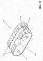
- FIGS. 11a-11bshow a magnetic rover delivery system 500 configured to be inserted into an access port 205 (e.g., hand hole) of a steam generator 200 or other vessel or enclosed area.
- the overall dimensions of the magnetic rover 500are about 20 cm (8") in length, 8.1 cm (3.2") in height, and 8.9 cm (3.5") in width.
- the magnetic rover 500 systemis deployable on steam generator models having the Flow Distribution Baffle (FDB) on center or below the hand hole access which have at a minimum a 102 mm (4") access port or hand hole, wrapper cutouts in the support plates in 95.25 mm (3.75") wide and 91.4 mm (3.6”) in depth measured from the wrapper tangent to the back of the cut. If the FDB is above the hand hole access the FDB must also contain these cutouts.
- FDBFlow Distribution Baffle
- the operator of the magnetic rover 500is located outside of the steam generator (e.g., remotely) and uses a user interface (e.g., GUI, joystick, etc.) to receive sensor feedback from the magnetic rover 500 (e.g., visual feedback, GPS signal, etc.) to control the movement of the magnetic rover.
- the magnetic rover 500comprises rare earth magnets (e.g., neodymium, etc.) or electromagnets in the tracks 554 or under tracks 554 (or wheels, optionally provided with scrapers).
- the total number of magnets in the trackscould vary. In some aspects, there are approximately twenty magnets distributed along each track. In various aspects, the total magnetic force required to maintain the magnetic rover firmly in place when vertically disposed on the wrapper would exceed 22.2 Newtons (5 pounds of force) and would still more preferably exceed about 44.4 Newtons (10 pounds of force).
- the tracks 554may comprise a rubber lug type track or a custom rubber track with magnet lugs.
- a plurality of separate, independently actuatable electromagnetse.g., front, mid, rear
- the magnetic tracks 554(or wheels) permit the magnetic rover 500 to climb vertically along the inner diameter (ID) of the steam generator wrapper 201 between the wrapper 201 and the tube 203 bundle and through openings 210 in the tube support plates 225, such as the openings 210 in the FRAMATOME 68/19 steam generator, as shown in FIG. 12a .
- the magnetic tracks 554 (or wheels)are advantageously, but not necessarily, configured to permit the magnetic rover to also move while upside down.
- FIGS. 11a-11ba forward-facing camera 555 and associated lights 556 (e.g., LEDs, etc.) are provided for navigation.
- a storage bay 558is also provided.
- FIG. 11bshows an in-bundle rover 160, as described above, deployed from the storage bay 558 of the magnetic rover 500, the in-bundle rover 160 being connected to the magnetic rover 500 by retractable cabling 169, as previously described.
- a plurality of position and inspection cameras (e.g., HD CCD camera) 557 and corresponding lights (e.g., white LEDs)(not shown) for illuminationare advantageously provided in locations about the magnetic rover 500 to provide extensive, potentially even redundant, image data for positional feedback and inspection.
- the magnetic rover 500utilizes the in-bundle rover 160 to deliver inspection cameras in-bundle, allowing the inspection of many attainable columns of tubes.
- one camera/lighting assembly 555is mounted on the front of the crawler and two camera/lighting assemblies are mounted on the lateral sides of the magnetic rover. It is advantageous, but not necessary, for the magnetic rover 550 to comprise a combination of different camera systems of differing cover, such as one or more color camera(s) utilizing LED lighting and one or more infrared cameras utilizing infrared LED's.
- the magnetic rover 500 chassiscomprises a main frame having dual polymer/magnet tracks 554 are mounted on opposing sides of the frame centerline.
- the polymer/magnet tracks 554are independently driven by DC servo-gear motors for use with a closed loop control system or by DC stepper motors allowing use of an open loop control system.
- the main framealso advantageously houses an electromagnet, or a plurality of electromagnets, utilizable during deployment of the magnetic rover 500 to the various support plate 225 elevations.
- an actuator member 550such as an electro-mechanical or pneumatic arm, configured to aids the magnetic rover's 500 egression from the wrapper 201 onto the support plate 225 and vice versa by pushing the rover away from or lifting it up to the wrapper.
- FIG. 12bshows the magnetic rover 500 in an intermediate position transitioning between movement along the steam generator wrapper 201 to movement along the support plate 225.
- the actuator member 550is configured to push against the wrapper 201 to counter the magnetic forces causing the magnetic rover 500 to adhere to the wrapper.
- the actuator member 550pushes against the wrapper 201 and rotates generally synchronously with the forward motion of the magnetic rover 500, thereby causing the magnetic rover to separate from the wrapper with an increasing angle for increased forward movement of the magnetic rover.
- the center of gravity of the magnetic rover 500will shift sufficiently so that gravity will pull the front part of the magnetic rover down to the position shown in FIG. 12c .
- the magnetic rover 500may be employed to achieve separation of the magnetic rover 500 from the wrapper 201, such as but not limited to, a pneumatic nozzle blowing compressed air or an extendable linear actuator.
- the magnetic rovercomprises a plurality of electromagnets
- the front, mid, and then rear electromagnetsare sequentially deactivated to facilitate the separate of the magnetic rover 500 from the wrapper 201 in conjunction with the action of the actuator member.
- FIG. 12cshows the magnetic rover 500 positioned over the opening 210 (not shown in FIG. 12c ), wherein it is able to then resume movement along the support plate 225 to any desired location, as is generally shown in FIGS. 12g-12h (or optionally to return and move downwardly back through the opening 210).
- FIG. 12dshows the magnetic rover 500 on a support plate 225 in the tube lane region between the hot legs and cold legs of the U-tubes 203.
- the magnetic rover 500is configured to both perform inspections and to deploy an in-bundle rover 160, described above, and does not require use of the VDS 100, described above, or other related systems developed by R. Brooks Associates of Williamson, New York, shown by way of example in U.S. Pat. No. 6,145,583 and U.S. Pat. No. 5,265,129 , to get into position.
- FIGS. 12e-12fshow the magnetic rover 500 positioned midway into the opening 210 as it returns back into contact with the steam generator wrapper 201, wherein it would then be able to resume movement upwardly or downwardly along the wrapper.
- the actuator member 550is deployed differently than that described above with respect to the movement of the magnetic rover 500 onto the support plate 225. Specifically, the actuator member 550 is shown to provide a resistive force against the support plate to retard downward motion of the magnetic rover 500. As the magnetic rover 500 moves into greater and greater contact with the wrapper, the actuator member 550 is rotatable out of the way so as to permit increased forward movement of the magnetic rover. At some point, the magnetic force of the magnetic rover 500 magnets are sufficiently to securely adhere the magnetic rover to the wrapper.
- FIGS. 12g-12hshow the in-bundle rover 160 in a deployed position wherein the in-bundle inspection rover, under the control of its own drive system 162 (e.g., belt(s), track(s), wheels, etc.) moves laterally away from the magnetic rover 500 and into the tube 203 bundle region.
- the in-bundle rover 160itself comprises, as noted above, a variety of cameras (e.g., front, rear, down) and associated lights (e.g., white LEDs) providing positional data useful for maneuvering and/or positioning the in-bundle rover, as well as for obtaining useful inspection data.
- the magnetic rover 500is controlled via cabling 539 containing all associated control, video and auxiliary conductors for operation of the magnetic rover, in-bundle rover 160 and all associated systems (e.g., lighting, video, actuators, etc.).
- On-board equipment for the magnetic rover 500 and/or the in-bundle rover 160may include, but is not limited to, camera/LED units of various type (e.g., color, black and white, IR, etc.) allowing a wide range of viewing options, to stored examination probes/devices, sensors, and tools and retrieval tooling that may be deployed from the magnetic rover 500 storage bay 558 or another storage bay.
- a robotic arm(not shown) may be used to attach and remove a variety of tools and sensors to corresponding ports of the in-bundle rover 160.
- the magnetic rover 500 systemadvantageously utilizes a cable management system like that shown in U.S. Pat. Application No. 12/714,090 , titled “Inspection System And Inspection Process Utilizing Magnetic Inspection Vehicle,” which is assigned to the assignee of the present application, and which is incorporated herein by reference in its entirety, to feed in and feed out the appropriate amount of cabling.
- Such cable management systemfeeds and controls the cables and tubes linking the magnetic rover 500 to external systems (e.g., computer used by operator, open loop control box, etc.) and comprises, for example, a mount flange to permit the cable management system to be mounted to the steam generator access port 205 and a roller housing that houses the rollers and motors that grip or "pinch" the cabling to positively drive it into or out of the steam generator responsive to or synchronously with control signals provided by the operator to the magnetic rover.
- Electric drive motorssuch as MicroMo 2842S012S + 30/1 246:1 motors, may be used in combination with rollers to pinch and push the cable in or out of the access port.
- the cable management systemalso advantageously comprises a tension adjuster comprising a shaft that can be pulled to facilitate cable installation and a spring to maintain tension on the cable(s).
- An electrical interface boxcomprises the electrical connection point or interface between the internal electric DC servo motors of the cable management system and the control module, the open loop control system (OLCS).
- OLCSopen loop control system
- a motorized cable feederis then mounted to the access port mount and the cable 539 inserted through a cable slot by pulling up on a spring loaded plate. When the cable 539 is properly positioned between the feed wheels, the spring plate is released and both the front and back cable 539 positioned and held in place.
- the cable containeris positioned directly behind the cable management system and
Landscapes
- Engineering & Computer Science (AREA)
- Physics & Mathematics (AREA)
- High Energy & Nuclear Physics (AREA)
- General Engineering & Computer Science (AREA)
- Mechanical Engineering (AREA)
- Thermal Sciences (AREA)
- Plasma & Fusion (AREA)
- Transportation (AREA)
- Combustion & Propulsion (AREA)
- Chemical & Material Sciences (AREA)
- Monitoring And Testing Of Nuclear Reactors (AREA)
- Investigating Materials By The Use Of Optical Means Adapted For Particular Applications (AREA)
- Investigating Or Analyzing Materials By The Use Of Magnetic Means (AREA)
Description
- The present invention relates to the field of inspection devices generally, and more specifically to power plant steam generator inspection devices, and still more specifically to nuclear power plant steam generator inspection devices.
- In a nuclear reactor power plant, a nuclear reactor vessel is used to generate heat for the production of steam and electricity. The reactor vessel is typically a pressurized vessel enclosing a core of nuclear fuel and cooling water. Such nuclear power plants typically contain three major components: a reactor vessel containing fuel which produces superheated water for transport to one or more steam generators, which output steam to drive a multistage steam turbine to generate electric power.
- The superheated water is transported to the steam generator by pipes. These pipes feed the water into numerous tubes within the steam generator. These tubes are U-shaped, feeding the water back to the pipes at the outlet of the steam generator to be re-circulated back to the reactor. The tubes in a nuclear steam generator typically form an inverted "U" separated by a lane, and held together by a plurality of support plates, separated at periodic vertical intervals. The height of each tube row may exceed 9.8 meters (32 feet). Six to eight or more support plates are used, each separated vertically at 0.9 to 1.8 meter (3 to 6 foot)
intervals. In the
steam generator, the tube carrying the superheated water are quenched with cool water, which generates the steam which drives the turbine to produce electricity. - This procedure for generating steam presents several problems. The water used to quench the tubes often has impurities and chemicals which may corrode both the steam generator tubes and the support plates and lead to other damage. Even though periodic inspections of nuclear steam generators are required for compliance with safety regulations, monitoring steam generator cleanliness remains a problem. The highly corrosive environment of the steam generator is particularly problematic for many of the older nuclear reactors in service throughout the world.
- In the past, steam generator tubes and support plates were inaccessible for visual inspection. Information was gathered by complicated systems which could not adequately inspect all sections of tubes and support plates. Because of the highly radioactive environment and the heat of the pipes, direct visual human inspection has typically been restricted to between three and five minutes per man per six month period. This time period does not provide ample opportunity for the careful inspection for corrosion, holes and leaks. It is therefore difficult to inspect within the narrow lanes and tube separation gaps at the support plates, because of the heat, radioactivity and narrowness of the lanes separating the tubes.
Inspection systems of various types and fields of application are
shown byEP A 0423013 ,JP2007161273 US6887014B2 . - Tubes typically extend through support plates at quatrefoil holes. These openings provide flow through features to improve water flow in the generator and to reduce the build-up of sediment at the support plates. Nevertheless, the small areas where the quatrefoil opening must contact the tube results in areas of material build-up on the tubes, or even adherence of material being "plated out" on the tubes. This material will contribute to premature corrosion of the tubes. With known inspection devices, this condition will go undetected on all but the tubes bordering the lane.
- Further, the orientation of component parts within steam generators provides extreme challenges to designing workable devices for inspecting such areas. Insertion holes (also known as hand holes) at the bottom of the steam generators are often as small as a five or six inch diameter. For the purpose of this application such portals will be referred to inclusively as access ports. Flow distribution baffles within the generator often obstruct any room to maneuver equipment within the generator. Inspection within steam generators at elevations as high as nine meters (thirty feet)
or more provide significant engineering challenges. In
addition, the flow slots between tube rows are often less than two inches wide and tube separation gap dimensions are often less than 2.5 cm (one inch), down to 0.76 cm (0.30 inches). - In some aspects of the present concepts, an inspection system to inspect a secondary side of a steam generator includes all features of independent claim 1.
- In another aspect of the present concepts, a method of inspecting a secondary side of a steam generator includes all features of
independent claim 8. - The above summary of the present invention is not intended to represent each embodiment, or every aspect, of the present invention. Additional features and benefits of the present invention will become apparent from the detailed description, figures, and claims set forth below.
- Other objects and advantages of the invention will become apparent upon reading the following detailed description in conjunction with the drawings.
FIG. 1 shows a perspective view of a vertical deployment system (VDS) for steam generators in accord with at least some aspects of the present concepts.FIGS. 2a-2b show views of a portion of the VDS ofFIG. 1 showing a delivery capsule in accord with at least some aspects of the present concepts.FIG. 3 shows the VDS of the preceding figures inserted into a steam generator in accord with at least some aspects of the present concepts.FIG. 4 shows the VDS of the preceding figures in an installed and collapsed state in a steam generator in accord with at least some aspects of the present concepts.FIG. 5 shows the VDS of the preceding figures in an installed and extended state in a steam generator in accord with at least some aspects of the present concepts.FIG. 6 shows another view of the VDS of the preceding figures in an installed and extended state in a steam generator in accord with at least some aspects of the present concepts.FIG. 7 shows another view of the VDS of the preceding figures in an installed and extended state in a steam generator, wherein a rover is deployed, in accord with at least some aspects of the present concepts.FIG. 8 shows another view of the delivery capsule, deployed rover and deployed in-bundle rover in accord with at least some aspects of the present concepts.FIG. 9 shows a view of the delivery capsule with the rover retained therein in accord with at least some aspects of the present concepts.FIG. 10 shows a view of a deployed rover and deployed in-bundle rover in accord with at least some aspects of the present concepts.FIG. 11a show another embodiment of an inspection vehicle for inspection steam generators in accord with at least some aspects of the present concepts.FIG. 11b shows the inspection vehicle ofFIG. 11a deploying an in-bundle rover in accord with at least some aspects of the present concepts.FIGS. 12a-12c show a sequence of movement of the inspection vehicle ofFIGS. 11a-11b in accord with at least some aspects of the present concepts transitioning from movement along the steam generator wrapper to a steam generator support plate.FIG. 12d is a front view of an inspection vehicle in accord with at least some aspects of the present concepts disposed on a top steam generator support plate.FIGS. 12e-12f show a sequence of movement of the inspection vehicle ofFIGS. 11a-11b in accord with at least some aspects of the present concepts transitioning from movement along a steam generator support plate to the steam generator wrapper.FIGS. 12g-12h are perspective cut-away views of an inspection vehicle deploying an in-bundle rover in accord with at least some aspects of the present concepts disposed on a top steam generator support plate.FIG. 13 shows another view of the inspection vehicle ofFIGS. 11a-11b in accord with at least some aspects of the present concepts.FIG. 14 shows an example of a control layout for the VDS ofFIGS. 1-10 .- While the invention is susceptible to various modifications and alternative forms, specific embodiments have been shown by way of example in the drawings and will be described in detail herein. It should be understood, however, that the invention is not intended to be limited to the particular forms disclosed. Rather, the invention is defined by the appended claims.
FIGS. 1-9 show various aspects of a vertical deployment system (VDS) 100 generally corresponding in structure to the device for inspecting the interior of steam generators disclosed inU.S. Patent No. 6,145,583, issued on November 14, 2000, to Gay et al. , which device is configured to visually inspect steam generator tubes, including upper portions of steam generator tubes, tops and bottoms of support plates, wrapper-to-support plate welds, and other steam generator internal structures.- In general, the
VDS 100 is designed for a vertical lift of instruments, sensors, tools and/or payloads about 9-10 meters (30-33 feet)
or more, depending on the structure of the particular
type of steam generator to be inspected. In the accompanying figures, the steam generator represented is the FRAMATOME model 68/19, but the VDS may be utilized in other steam generators such as, but not limited to the Westinghouse Model F steam generator and other steam generators. TheVDS 100 is deployable on steam generator models having the Flow Distribution Baffle (FDB) 275 (seeFIG. 3 ) on center or below the hand hole access which have at a minimum a 102 mm (4") diameter clear access into the steam generator. In an alternative configuration, a deployable support may be utilized in combination with therail assembly 110 to provide a support to another steam generator component or surface. In yet another configuration, the rail assembly may be simply connected to theaccess port 205 such that the rail assembly is cantilevered within the steam generator. The steamgenerator support plates 225 must also contain flow holes in the approximate dimension of about 89 mm (3.5")
in diameter or equivalent in width for a rectangular cut out, or larger. - The
VDS 100 comprises two main structural components, a rail assembly 110 (e.g., a "first boom") and a telescoping boom assembly 120 (e.g., "second boom"). In at least some aspects of the present concepts, thetelescoping boom assembly 120 comprises a hydraulically-actuated stacked cylinder set and, at a distal end, adelivery capsule 130, described below. - The
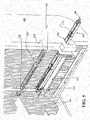
rail assembly 110 of theVDS 100, as is shown inFIGS. 1-5 , for example, is disposed through anaccess port 205 of thesteam generator 200 wall and is attached to an access port flange (not shown) by an access port mounting plate (not shown). When therail assembly 110 is attached, at a proximal end, to theaccess port 110, the rail assembly provides a stabilization leg that provides system stability for deployment of thetelescoping boom assembly 120, such as is shown inU.S. Pat. No. 5,265,129 ,U.S. Pat. No. 5,504,788 , andU.S. Pat. No. 6,145,583 . The railassembly 110 attaches, at a distal end, to thetelescoping boom assembly 120 at apivot clamp 135 that can be manually actuated or actuated via a conventional actuating device, such as a rotary actuator or a linear actuator. - In at least one configuration, a rack drive servo motor attaches to the access port mounting plate and a manual crank
handle 140 drives a linkage (e.g., gear(s) or gear(s) and rod(s)) attached at a distal end to thepivot clamp 135, which is secured to thetelescoping boom assembly 120. Once theVDS 100 is inserted in thru the tube lane or "no-tube lane" as it is sometimes called, shown inFIGS. 3-5 , and secured, thetelescoping boom assembly 120 can then be up-righted using the mechanical crankhandle 140. The tube lane is the narrow area created by the innermost inverted U-tubes. Steam enters one side of the U-bend (the hot pipe) and travels around the U-bend of the pipe and is quenched by the cool water in the steam generator and proceeds around to the other side of the U-bend (the cool pipe). The manual crank handle 140 is operatable to both deploy thetelescoping boom 120 and to retract the telescoping boom to the retracted position for extraction of theVDS 100. In lieu of the manual crank, one or more actuators (e.g., linear actuator(s), rotary actuator(s), or combination thereof, etc.) could alternatively be used. As is shown inFIG. 3 , following securement of theVDS 100 to theaccess port 205 of thesteam generator 200, the retracted or folded VDS is extended horizontally into the steam generator through the flanged access port and through thesteam generator wrapper 201. In this configuration, thetelescoping boom assembly 120 is aligned to be substantially parallel with therail assembly 110 to facilitate insertion through theaccess port 205. - The
VDS 100 is disposed initially near the base of thesteam generator 200 in the tube lane, the narrow area created by the innermost invertedU-tubes 210, and more specifically through the "no-tube lane" thereof, as is shown inFIG. 3 . In this installed configuration, theVDS 100 system is about 229 cm (90") long, 10 cm (4") high, and 10 cm (4") wide. This length can
be adjusted to a greater or lesser length during the installation process via insertable and removable section if the plant geometry and drawback requirements dictate. - Once the
VDS 100 is installed horizontally through the access portion, as shown inFIG. 3 , thetelescoping boom assembly 120 anddelivery capsule 130 borne thereby is raised to a vertical position in the tube lane to a height of about 76 cm (30"), and extended via actuation of thetelescoping boom assembly 120 stacked cylinder set, through aflow slot 220 in thesupport plates 225 of the steam generator, as is shown inFIG. 4 .FIG. 5 shows continued extension of thetelescoping boom assembly 120 anddelivery capsule 130 borne to successivelyhigher flow slots 220 inhigher support plates 225, as is further shown inFIG. 6 . - A
camera 134 is provided at a top portion of thedelivery capsule 130 and may comprise a fixed camera or, as is shown inFIG. 2b , a pan, tilt and/or zoom camera. Thedelivery capsule 130 itself may be fixed to a distal end oftelescoping boom assembly 120 or may alternatively be rotatably attached thereto with an associated drive system (e.g., motor, rotary actuator, etc.) to rotate thedelivery capsule 130 through a selected range. Thecamera 134 enhances the operator's ability to navigate thedelivery capsule 130 vertically through theflow slots 220 and, for the pan, tilt and/or zoom embodiment, provides additional visual inspection capability as well.FIG. 7 shows thedelivery capsule 130 extending through aninner flow slot 220 above asteam generator 200support plate 225. - The
rail assembly 110 is configured to be moved in or out of thesteam generator 200 to align thetelescoping boom assembly 120 with a desired one of the flow slots along thesupport plates 225. Therail assembly 110 may be moved back and forth slightly or jogged to facilitate vertical movement of thetelescoping boom assembly 120 so as to keep thedelivery capsule 130 aligned with theflow slot 220 in eachsupport plate 225. Thetelescoping boom assembly 120 is able to extend telescopically to any desired vertical position in thesteam generator 200 along theflow slots 220. As noted above, thesupport plates 225 are disposed in a spaced relation vertically throughout the height of the steam generator at about three foot to six foot intervals, depending on the make and model of the steam generator. - As is represented in
FIGS. 3-5 , for example, the hydraulically-controlledtelescoping boom assembly 120 is activated to extend vertically to a desired height within thesteam generator 200. The vertical movement of thetelescoping boom assembly 120 and/or horizontal movement of therail assembly 110 may be computer-controlled or, alternatively, manually controlled. When thetelescoping boom assembly 120 is initially deployed into a vertical position at a desired horizontal position, the horizontal position is verified. This verification may be accomplished either visually (e.g., by reference to the tube columns or other visual landmarks), via mechanical or electromechanical devices (e.g., mechanical distancing apparatuses, such as pulleys or gears, rotary encoders, etc.), or via one or more positioning sensors. To facilitate horizontal or lateral movement of thetelescoping boom assembly 120, a registration apparatus is preferably provided, the registration apparatus (not shown) comprising sets of registration guides (e.g., finger-like projections) that can be selectively pneumatically powered outwardly from a retracted position at rest or inwardly from an extended position. When each guide set is extended, one guide set contacts the hot leg of a U-tube and one guide set contacts the "cold" leg of the same U-tube. - Hydraulic control of the
telescoping boom assembly 120 is provided by a conventional electrically driven hydraulic pump system. The presently preferred hydraulic pump for thetelescoping boom assembly 120 comprises a centrifugal vane pump, pressure relief valve, two proportional control valves, a solenoid block valve, a fluid reservoir and pressure gauges. Control power and signals are fed from the main control console over a single cable and main 110V AC power to operate the pump is obtained from a source local to the pump. Thetelescoping boom assembly 120 may alternatively comprise a pneumatically-driven design, as opposed to hydraulically-driven. - Operation of the
VDS 100 are controlled by a main operating station where data from the VDS instrumentation and cameras (and systems deployed by the VDS) are stored in or on a physical storage media and/or viewed.FIG. 14 is a schematic of one potential control layout for theVDS 100.Area monitor 300,control interface computer 302, optional auxiliary electronics 304, andhydraulic pump 306 are preferably positioned outside of abioshield 308 and have theircables 310 directed to controlelectronics 312 and power and air supplies 314, which are set up adjacent the generator access opening 321. A rack andpinion drive 316 is attached torail assembly 110 which is attached to pivotclamp 135. The control hardware for the present invention is optionally divided into primary control hardware and operator station hardware, wherein the primary control hardware is set up at the steam generator platform. In this configuration, the primary control hardware comprises two small suitcase-sized cases main control console 312 and thesecond case 314 containing bulk power supplies. Plant supplied AC power and compressed air are supplied to these cases for system operation. A switching-type power supply provides power to computer hardware from the main control console case. - The
main control console 312 provides the system manual control capability. Power for motor loads, lighting, cameras and support circuitry is supplied by the bulkpower supply case 314 via appropriateelectrical connectors 317.Line 318 represents control cabling for thedelivery capsule 130 and all associated systems including, but not limited to, electrical power cable, A/V cables, pneumatic supply line, etcetera, to operate all delivery capsule systems and subsystems. All system component connections terminate at themain control console 302. The operator station for the device preferably contains acontrol computer 302, running a graphical user interface (e.g., a Microsoft Windows® platform), associated control hardware 304,video monitoring 300 and recording equipment and audio communication equipment. In one embodiment, audio communications link the steam generator platform and the operator station to assist in setup, installation, and/or operation. - As described above, the
VDS 100 is used to access internal regions of steam generators, specifically thevarious support plate 225 elevations. Following extension of a distal end of thetelescoping boom assembly 120 to a desiredsupport plate 225, such as is shown inFIG. 7 , a robot or "rover" 150 is deployed from thedelivery capsule 130, such as is shown inFIG. 8 . Therover 150 is controlled via a tether/umbilical cable 155 housing all control, video and auxiliary conductors necessary for operation of and positive retention of therover 150 and all associated systems. On-board equipment for therover 150 may comprise, but is not limited to, one or more cameras or video recording devices, one or more LED packages or other lighting systems, one or more examination probes, an eddy current sensor and deployment tool, and/or retrieval tooling. - The
rover 150 chassis comprises amain frame 152 to which all components are attached to or reside within. Twin polymer tracks 154 are mounted on either side of the frame centerline and are independently driven by respective DC servo-gear motors for use with a closed loop control system or by DC stepper motors allowing use of an open loop control system. - To facilitate operation and examination of steam generator internals, a plurality of on-board camera assemblies are advantageously provided to provide visual feedback not only of the steam generator internals, but also of the immediately surroundings of the rover, such as to facilitate navigation. In one aspect, a
first camera assembly 155, which may be a black and white camera or a color camera utilizing LED lighting or an infrared camera utilizing infra red LEDs, is mounted on the front of the crawler. In another aspect, a second camera assembly (not shown) is mounted on another side of the rover 150 (e.g., a back side or a lateral side). These camera systems for therover 150, where a plurality of cameras are provided, advantageously comprise a mix of color cameras, utilizing LED lighting, and infrared cameras utilizing infra red LED's. Examination of the no-tube lane, or other accessible portions of the steam generator, may be accomplished using one or more of therover 150 cameras while the rover is securely retained within thedelivery capsule 130. - In-bundle examination (i.e., examination between the steam generator U-tubes 203) can be accomplished by deploying, from a cavity or
storage bay 158 of therover 150, a small, mechanized in-bundle rover 160 that itself comprises on-board video and lighting (color video, IR, UV, CCD, etc.) and optionally, one or more additional sensors and/or tools (e.g., a retrieval tool). The in-bundle rover comprises a drive system (e.g., motor-operated belt(s), track(s), wheels, etc.) that permit the in-bundle inspection rover to move laterally away from therover 150 and into the tube bundle region. To facilitate movement of the in-bundle rover 160 between the steam generator U-tubes, the width of the in-bundle rover 160 must correspondingly be less than that of the spacing of adjacent U-tubes (e.g., less than 1.3 cm (0.5"), less than about 0.6 cm (0.25"), etc.)
and in at least one aspect is about 0.6 cm (0.25") in width. - The in-
bundle rover 160 comprises a forward facingcamera 164, such as a Q-SEE QMSCC ultra-mini color camera, manufactured by Digital Peripheral Systems, Inc. of Anaheim, California, which is 4.6 mm in diameter and approximately 17 mm in length. In another aspect, the on-board video and lighting of the in-bundle rover 160 comprises a video probe including a flexible stainless jacket, or a laminated flexible wand, containing structural reinforcement to provide structural support while allowing some flexibility and containing all associated camera and lighting conductors. Optionally, a rear facing camera and/or a down facing camera (front and/or rear) are also provided, with attendant lighting (e.g., LED, IR LED, etc.). The in-bundle rover 160 may also optionally comprise sensors (e.g., nondestructive testing/examination, etc.) and/or retrieval (e.g., grappling) tooling. - The in-
bundle rover 160 is attached to therover 150 by cabling (e.g., electrical cable, A/V cable, etc.) 169, which may be unified in an outer cable jacket, that is in turn connected to a rotating drum configured to let out and retract thecabling 169 as the in-bundle rover 160 moves outwardly and back, respectively, through thesteam generator tube 203 columns. In-bundle positioning of the in-bundle rover 160 is accomplished, in at least some aspects, using electronic encoding (e.g., a rotary encoder used in combination with the rotating drum) in combination with the on-board video capabilities to provide feedback on the deployed distance and tube position. - Once the
VDS 100 is inserted and thetelescoping boom assembly 120 is locked in the upright position, a stabilization leg (not shown) is lowered to further stabilize the system. Thetelescoping boom assembly 120 is then deployed vertically via the stacked hydraulic cylinder to the desired support plate elevation with height positional feedback provided by sensors, such as string encoders. Once thedelivery capsule 130 is at the desired elevation, therover 150 may be deployed from the delivery housing onto thesupport plate 225, index the tube columns and begin examinations utilizing its on-board video system. Retrieval of the system begins with recalling the in-bundle rover 160 into thestorage bay 158 of therover 150, recalling therover 150 into thestorage bay 132 of thedelivery capsule 130. Once therover 150 is secured in position, the stack cylinder set slowly releases fluid pressure to lower the system to the collapsed state shown inFIG. 4 and then into the insertion state shown inFIG. 3 by rotation of thetelescoping boom assembly 120. TheVDS 100 may then be disengaged from theaccess port 205 and removed. - The hydraulically-controlled
telescoping boom assembly 120 is then activated allowing the device to extend vertically to the desired height which may cause the device to proceed through the flow slots ofsuccessive support plates 225. Computer-controlled or manually controlled machinery sensitively and accurately measures the height of the distal end of thetelescoping boom assembly 120 to ensure precise vertical positioning and of the delivery capsule within thesteam generator 200. In conjunction with the vertical extension and monitoring of the vertical position of thetelescoping boom assembly 120, the horizontal position of thetelescoping boom assembly 120 is also preferably verified visually (e.g., via thedelivery capsule camera 134 and/or numerically (e.g., encoder, mechanical distancing apparatuses such as pulleys or gears, position sensors, pattern recognition sensors, etc.). Horizontal movement of thetelescoping boom assembly 120 may be accomplished, for example, using a pneumatically-powered registration apparatus to sequentially extend and retract sets of registration guides, finger-like movable members configured to extend from a first position to a second position, to provide a "walking" motion. When each registration guide set is extended, one guide will contact the hot tube and, on the opposing side, another guide will contact the cool tube of the same U-tube. - Thus, in accord with the above-described
VDS 100 androvers support plate 225, deploy therover 150 to a desired position along the center lane of the support plate, and further deploy the in-bundle rover 160, which, as noted above, comprises its own drive system (e.g., belt(s), track(s), wheels, etc.) that permit the in-bundle inspection rover to move laterally away from the plate rover and into the tube bundle region. FIGS. 11a-11b show a magneticrover delivery system 500 configured to be inserted into an access port 205 (e.g., hand hole) of asteam generator 200 or other vessel or enclosed area. The overall dimensions of themagnetic rover 500 are about 20 cm (8") in length, 8.1 cm (3.2") in height, and 8.9 cm (3.5")
in width. Themagnetic rover 500 system is deployable on steam
generator models having the Flow Distribution Baffle (FDB) on center or below the hand hole access which have at a minimum a 102 mm (4") access port or hand hole, wrapper cutouts in the support plates in 95.25 mm (3.75") wide and 91.4 mm (3.6") in depth measured from the wrapper tangent to the back of the cut. If the FDB is above the hand hole access the FDB must also contain these cutouts.- The operator of the
magnetic rover 500 is located outside of the steam generator (e.g., remotely) and uses a user interface (e.g., GUI, joystick, etc.) to receive sensor feedback from the magnetic rover 500 (e.g., visual feedback, GPS signal, etc.) to control the movement of the magnetic rover. Themagnetic rover 500 comprises rare earth magnets (e.g., neodymium, etc.) or electromagnets in thetracks 554 or under tracks 554 (or wheels, optionally provided with scrapers). The total number of magnets in the tracks could vary. In some aspects, there are approximately twenty magnets distributed along each track. In various aspects, the total magnetic force required to maintain the magnetic rover firmly in place when vertically disposed on the wrapper would exceed 22.2 Newtons (5 pounds of force) and would
still more preferably exceed about 44.4 Newtons (10 pounds of force). - By way of example, the
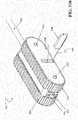
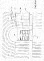
tracks 554 may comprise a rubber lug type track or a custom rubber track with magnet lugs. In another example, a plurality of separate, independently actuatable electromagnets (e.g., front, mid, rear) are provided. The magnetic tracks 554 (or wheels) permit themagnetic rover 500 to climb vertically along the inner diameter (ID) of thesteam generator wrapper 201 between thewrapper 201 and thetube 203 bundle and throughopenings 210 in thetube support plates 225, such as theopenings 210 in the FRAMATOME 68/19 steam generator, as shown inFIG. 12a . The magnetic tracks 554 (or wheels) are advantageously, but not necessarily, configured to permit the magnetic rover to also move while upside down. - As shown in
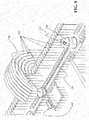
FIGS. 11a-11b , a forward-facingcamera 555 and associated lights 556 (e.g., LEDs, etc.) are provided for navigation. Astorage bay 558, described below, is also provided.FIG. 11b shows an in-bundle rover 160, as described above, deployed from thestorage bay 558 of themagnetic rover 500, the in-bundle rover 160 being connected to themagnetic rover 500 byretractable cabling 169, as previously described. A plurality of position and inspection cameras (e.g., HD CCD camera) 557 and corresponding lights (e.g., white LEDs)(not shown) for illumination are advantageously provided in locations about themagnetic rover 500 to provide extensive, potentially even redundant, image data for positional feedback and inspection. - To access the in-bundle region, the
magnetic rover 500 utilizes the in-bundle rover 160 to deliver inspection cameras in-bundle, allowing the inspection of many attainable columns of tubes. In one aspect, one camera/lighting assembly 555 is mounted on the front of the crawler and two camera/lighting assemblies are mounted on the lateral sides of the magnetic rover. It is advantageous, but not necessary, for themagnetic rover 550 to comprise a combination of different camera systems of differing cover, such as one or more color camera(s) utilizing LED lighting and one or more infrared cameras utilizing infrared LED's. - The
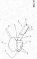
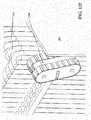
magnetic rover 500 chassis comprises a main frame having dual polymer/magnet tracks 554 are mounted on opposing sides of the frame centerline. The polymer/magnet tracks 554 are independently driven by DC servo-gear motors for use with a closed loop control system or by DC stepper motors allowing use of an open loop control system. Combined with themagnetic tracks 554, the main frame also advantageously houses an electromagnet, or a plurality of electromagnets, utilizable during deployment of themagnetic rover 500 to thevarious support plate 225 elevations. Mounted on the side of themagnetic rover 500 track carriage is anactuator member 550, such as an electro-mechanical or pneumatic arm, configured to aids the magnetic rover's 500 egression from thewrapper 201 onto thesupport plate 225 and vice versa by pushing the rover away from or lifting it up to the wrapper. FIG. 12b shows themagnetic rover 500 in an intermediate position transitioning between movement along thesteam generator wrapper 201 to movement along thesupport plate 225. Theactuator member 550, noted above, is configured to push against thewrapper 201 to counter the magnetic forces causing themagnetic rover 500 to adhere to the wrapper. Theactuator member 550 pushes against thewrapper 201 and rotates generally synchronously with the forward motion of themagnetic rover 500, thereby causing the magnetic rover to separate from the wrapper with an increasing angle for increased forward movement of the magnetic rover. At some point, the center of gravity of themagnetic rover 500 will shift sufficiently so that gravity will pull the front part of the magnetic rover down to the position shown inFIG. 12c .- Alternatively, other devices may be employed to achieve separation of the
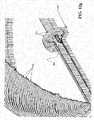
magnetic rover 500 from thewrapper 201, such as but not limited to, a pneumatic nozzle blowing compressed air or an extendable linear actuator. Where the magnetic rover comprises a plurality of electromagnets, the front, mid, and then rear electromagnets are sequentially deactivated to facilitate the separate of themagnetic rover 500 from thewrapper 201 in conjunction with the action of the actuator member. FIG. 12c shows themagnetic rover 500 positioned over the opening 210 (not shown inFIG. 12c ), wherein it is able to then resume movement along thesupport plate 225 to any desired location, as is generally shown inFIGS. 12g-12h (or optionally to return and move downwardly back through the opening 210).FIG. 12d shows themagnetic rover 500 on asupport plate 225 in the tube lane region between the hot legs and cold legs of theU-tubes 203. Accordingly, themagnetic rover 500 is configured to both perform inspections and to deploy an in-bundle rover 160, described above, and does not require use of theVDS 100, described above, or other related systems developed by R. Brooks Associates of Williamson, New York, shown by way of example inU.S. Pat. No. 6,145,583 andU.S. Pat. No. 5,265,129 , to get into position.FIGS. 12e-12f show themagnetic rover 500 positioned midway into theopening 210 as it returns back into contact with thesteam generator wrapper 201, wherein it would then be able to resume movement upwardly or downwardly along the wrapper. In this operation, theactuator member 550 is deployed differently than that described above with respect to the movement of themagnetic rover 500 onto thesupport plate 225. Specifically, theactuator member 550 is shown to provide a resistive force against the support plate to retard downward motion of themagnetic rover 500. As themagnetic rover 500 moves into greater and greater contact with the wrapper, theactuator member 550 is rotatable out of the way so as to permit increased forward movement of the magnetic rover. At some point, the magnetic force of themagnetic rover 500 magnets are sufficiently to securely adhere the magnetic rover to the wrapper.FIGS. 12g-12h show the in-bundle rover 160 in a deployed position wherein the in-bundle inspection rover, under the control of its own drive system 162 (e.g., belt(s), track(s), wheels, etc.) moves laterally away from themagnetic rover 500 and into thetube 203 bundle region. The in-bundle rover 160 itself comprises, as noted above, a variety of cameras (e.g., front, rear, down) and associated lights (e.g., white LEDs) providing positional data useful for maneuvering and/or positioning the in-bundle rover, as well as for obtaining useful inspection data.- The
magnetic rover 500 is controlled viacabling 539 containing all associated control, video and auxiliary conductors for operation of the magnetic rover, in-bundle rover 160 and all associated systems (e.g., lighting, video, actuators, etc.). On-board equipment for themagnetic rover 500 and/or the in-bundle rover 160 may include, but is not limited to, camera/LED units of various type (e.g., color, black and white, IR, etc.) allowing a wide range of viewing options, to stored examination probes/devices, sensors, and tools and retrieval tooling that may be deployed from themagnetic rover 500storage bay 558 or another storage bay. For example, a robotic arm (not shown) may be used to attach and remove a variety of tools and sensors to corresponding ports of the in-bundle rover 160. - The
magnetic rover 500 system advantageously utilizes a cable management system like that shown inU.S. Pat. Application No. 12/714,090 , titled "Inspection System And Inspection Process Utilizing Magnetic Inspection Vehicle," which is assigned to the assignee of the present application, and which is incorporated herein by reference in its entirety, to feed in and feed out the appropriate amount of cabling. Such cable management system feeds and controls the cables and tubes linking themagnetic rover 500 to external systems (e.g., computer used by operator, open loop control box, etc.) and comprises, for example, a mount flange to permit the cable management system to be mounted to the steamgenerator access port 205 and a roller housing that houses the rollers and motors that grip or "pinch" the cabling to positively drive it into or out of the steam generator responsive to or synchronously with control signals provided by the operator to the magnetic rover. Electric drive motors, such as MicroMo 2842S012S + 30/1 246:1 motors, may be used in combination with rollers to pinch and push the cable in or out of the access port. The cable management system also advantageously comprises a tension adjuster comprising a shaft that can be pulled to facilitate cable installation and a spring to maintain tension on the cable(s). An electrical interface box comprises the electrical connection point or interface between the internal electric DC servo motors of the cable management system and the control module, the open loop control system (OLCS). To set up themagnetic rover 500 for inspection, a cable management mounting plate is installed to the access port and the magnetic rover is inserted into thesteam generator 200 and the cable (reference number 539 inFIG. 11a ) is threaded through the cable entry of the cable guide, which is then installed on the access port. A motorized cable feeder is then mounted to the access port mount and thecable 539 inserted through a cable slot by pulling up on a spring loaded plate. When thecable 539 is properly positioned between the feed wheels, the spring plate is released and both the front andback cable 539 positioned and held in place. The cable container is positioned directly behind the cable management system and cable coiled inside so to minimize any tangling. - The foregoing disclosure has been presented for purposes of illustration and description. The foregoing description is not intended to limit the present concepts to the forms, features, configurations, modules, or applications described herein by way of example. Other non-enumerated configurations, combinations, and/or sub-combinations of such forms, features, configurations, modules, and/or applications are considered to lie within the scope of the disclosed concepts.
Claims (15)
- A vehicular inspection system operable to inspect a secondary side of a steam generator, comprising:an inspection vehicle (500) including a body and a first drive system (554), the inspection vehicle (500) body defining a storage bay (558) and including an inspection camera (555), a lighting system (556), and cabling (539) connecting the inspection vehicle (500) to one or more of a cable management system, a video screen (300), a power supply (314), and a controller (312) outside of a steam generator (200),characterized in that:the first drive system has at least one first magnetic drive member (554) on a first lateral side of the body and at least one second magnetic drive member (554) on a second lateral side of the body opposite to the first lateral side, andthe vehicular inspection system further comprises an in-bundle robotic inspection vehicle (160) dimensioned to be borne by the storage bay (558) of the inspection vehicle (500), the in-bundle robotic inspection vehicle (160) including a second drive system (162), an inspection camera (164), a lighting system and cabling (169) connecting the in-bundle robotic inspection vehicle (160) to the inspection vehicle (500),wherein the inspection vehicle (500) further includes an actuator (550) operable to deploy an actuator member (550) against a first surface (201) of the secondary side of the steam generator (200) on which the inspection vehicle (500) is magnetically adhered to overcome a magnetic adhesion between the inspection vehicle (500) and the first surface (201) and to separate at least a portion of the at least one first magnetic drive member (554) and the at least one second magnetic drive member (554) from the first surface (201) to initiate transition of the inspection vehicle (500) from the first surface (201) to a second surface (225) of the secondary side of the steam generator (200), andwherein the first surface (201) is substantially vertical and the second surface (225) is substantially horizontal.
- The vehicular inspection system of claim 1, wherein the actuator (550) is further operable to deploy the actuator member (550) against the second surface (225) to retard an advancement of the inspection vehicle (500) when the inspection vehicle (500) transitions from the second surface (225) to the first surface (201) until such time as the inspection vehicle (500) is magnetically adhered to the first surface (201).
- The vehicular inspection system of claim 1 or 2, wherein the inspection vehicle (500) is about 20.3 cm in length, about 8.1 cm in height and about 8.9 cm in width.
- The vehicular inspection system according to any of claims 1-3, wherein a total magnetic force of the at least one first magnetic drive member (554) and the at least one second magnetic drive member (554) is between 22-44 N (5-10 pounds of force).
- The vehicular inspection system according to any of claims 1-4, wherein the at least one first magnetic drive member (554) includes a first track and the at least one second magnetic drive member (554) includes a second track.
- The vehicular inspection system according to claim 5, wherein the first track and the second track each include a plurality of spaced apart rare earth magnets, and preferably wherein the first track and the second track include rubber or polymer lugs, the plurality of spaced apart rare earth magnets being disposed within the lugs.
- The vehicular inspection system according to any of claims 1-6, wherein the actuator (550) is operable to selectively bias the actuator member (550) against a selected one of the first surface (201) or the second surface (225).
- A method of inspecting a secondary side of a steam generator (200) using an inspection vehicle (500), comprising:moving the inspection vehicle (500) with a drive system having magnetic drive members (554) vertically along a wrapper (201) of the steam generator (200) to a position beneath an opening (210) in a support plate (225) of the steam generator (200);moving the inspection vehicle (500) partially through the opening (210) in the support plate;actuating an actuator member (550), borne by the inspection vehicle (500), to push against a portion of the wrapper (201) above the opening (210) to separate the magnetic drive members (554) from the wrapper (201); andadvancing the inspection vehicle (500) through the opening (210) while the actuator member (550) applies a biasing force against the portion of the wrapper (201) above the opening (210) to cause the magnetic drive members (554) to progressively separate from the wrapper (201) until gravity acting on the inspection vehicle (500) pulls the inspection vehicle (500) onto the support plate.
- The method of claim 8, further including, prior to the moving of the inspection vehicle (500) vertically along the wrapper (201):
passing the inspection vehicle (500) through a hand hole (205) of the secondary side of the steam generator (200). - The method of claim 9, wherein the hand hole is at least 10.16 cm in diameter.
- The method of any of claims 8-10, further including:
deploying, from a storage bay (558) defined by a body of the inspection vehicle (500), an in-bundle robotic inspection vehicle (160) to perform in-bundle visual inspections using an inspection camera (164) and a lighting system. - The method according to any of claims 8-11, further including:moving the inspection vehicle (500) horizontally along the support plate (225) to a position adjacent the opening (210) in the support plate;moving a portion of the inspection vehicle (500) over the opening (210) in the support plate;actuating the actuator member (550) to contact a portion of the support plate (225) adjacent the opening (210) to retard downward motion of the inspection vehicle (500) through the opening (210);advancing the inspection vehicle (500) across the opening (210) until the magnetic drive members (554) contact the wrapper (201);advancing the inspection vehicle (500) through the opening (210), with the actuator member (550) contacting a portion of the support plate (225) adjacent the opening (210) to retard downward motion of the inspection vehicle (500) through the opening (210), to increase engagement of the magnetic drive members (554) to the wrapper (201); andmoving the actuating member out of engagement with the support plate (225) after the magnetic drive members (554) are adhered to the wrapper (201) and independently support the inspection vehicle (500).
- The vehicular inspection system according to claim 7, wherein the second drive system (162) includes one track beneath the in-bundle robotic inspection vehicle (160).
- The vehicular inspection system according to claim 13, wherein a width of the in-bundle robotic inspection vehicle (160) is between 6.35mm-12.7mm.
- The vehicular inspection system according to claim 13, wherein a width of the in-bundle robotic inspection vehicle (160) is about 6.35mm.
Priority Applications (1)
| Application Number | Priority Date | Filing Date | Title |
|---|---|---|---|
| SI201031940TSI3147910T1 (en) | 2009-05-27 | 2010-05-27 | A vehicular inspection system for inspecting a secondary side of a steam generator |
Applications Claiming Priority (3)
| Application Number | Priority Date | Filing Date | Title |
|---|---|---|---|
| US18156009P | 2009-05-27 | 2009-05-27 | |
| PCT/US2010/036489WO2010138774A1 (en) | 2009-05-27 | 2010-05-27 | Steam generator upper bundle inspection tools |
| EP10781249.7AEP2436012B1 (en) | 2009-05-27 | 2010-05-27 | Steam generator upper bundle inspection tools |
Related Parent Applications (1)
| Application Number | Title | Priority Date | Filing Date |
|---|---|---|---|
| EP10781249.7ADivisionEP2436012B1 (en) | 2009-05-27 | 2010-05-27 | Steam generator upper bundle inspection tools |
Publications (2)
| Publication Number | Publication Date |
|---|---|
| EP3147910A1 EP3147910A1 (en) | 2017-03-29 |
| EP3147910B1true EP3147910B1 (en) | 2019-07-10 |
Family
ID=43223097
Family Applications (2)
| Application Number | Title | Priority Date | Filing Date |
|---|---|---|---|
| EP16175434.6AActiveEP3147910B1 (en) | 2009-05-27 | 2010-05-27 | A vehicular inspection system for inspecting a secondary side of a steam generator |
| EP10781249.7AActiveEP2436012B1 (en) | 2009-05-27 | 2010-05-27 | Steam generator upper bundle inspection tools |
Family Applications After (1)
| Application Number | Title | Priority Date | Filing Date |
|---|---|---|---|
| EP10781249.7AActiveEP2436012B1 (en) | 2009-05-27 | 2010-05-27 | Steam generator upper bundle inspection tools |
Country Status (11)
| Country | Link |
|---|---|
| US (1) | US9251921B2 (en) |
| EP (2) | EP3147910B1 (en) |
| JP (2) | JP5968778B2 (en) |
| KR (2) | KR101708725B1 (en) |
| CN (2) | CN106885230B (en) |
| CA (1) | CA2763352C (en) |
| ES (2) | ES2753618T3 (en) |
| HU (2) | HUE045472T2 (en) |
| RU (1) | RU2548895C2 (en) |
| SI (2) | SI3147910T1 (en) |
| WO (1) | WO2010138774A1 (en) |
Families Citing this family (24)
| Publication number | Priority date | Publication date | Assignee | Title |
|---|---|---|---|---|
| KR101259822B1 (en)* | 2010-11-12 | 2013-04-30 | 삼성중공업 주식회사 | Moving appratus and method of working in hull block |
| FR2972071B1 (en)* | 2011-02-25 | 2013-04-26 | Sra Savac | DEVICE FOR INSPECTING A STEAM GENERATOR |
| US9168786B2 (en) | 2011-12-02 | 2015-10-27 | Helical Robotics, Llc | Mobile robot |
| US9920925B2 (en)* | 2013-12-20 | 2018-03-20 | Westinghouse Electric Company Llc | Steam generator sludge lance apparatus |
| CN104749183B (en)* | 2013-12-30 | 2017-07-14 | 中核武汉核电运行技术股份有限公司 | A kind of steam generator secondary side tube sheet video check instrument |
| CN105761766B (en)* | 2016-03-16 | 2017-07-11 | 武汉大学 | Nuclear containment high resolution image acquisition system |
| US12162160B2 (en) | 2016-12-23 | 2024-12-10 | Gecko Robotics, Inc. | System, apparatus and method for improved location identification with prism |
| US11673272B2 (en) | 2016-12-23 | 2023-06-13 | Gecko Robotics, Inc. | Inspection robot with stability assist device |
| PL3974823T3 (en) | 2016-12-23 | 2024-07-15 | Gecko Robotics, Inc. | Inspection robot |
| US12358141B2 (en) | 2016-12-23 | 2025-07-15 | Gecko Robotics, Inc. | Systems, methods, and apparatus for providing interactive inspection map for inspection robot |
| US11307063B2 (en)* | 2016-12-23 | 2022-04-19 | Gtc Law Group Pc & Affiliates | Inspection robot for horizontal tube inspection having vertically positionable sensor carriage |
| KR102047312B1 (en)* | 2017-01-04 | 2019-11-22 | 한국수력원자력 주식회사 | Steam Generator Foreign Object Transfer Device |
| US10981280B2 (en) | 2017-10-16 | 2021-04-20 | Sensor Networks, Inc. | Mechanize retrieval tool with camera |
| WO2019204504A1 (en)* | 2018-04-17 | 2019-10-24 | Gecko Robotics, Inc. | Inspection robot for horizontal tube inspection |
| KR102013073B1 (en)* | 2018-10-15 | 2019-08-21 | 한전케이피에스 주식회사 | Endoscope conveyance device, endoscopic unit and remote inspection apparatus |
| CN109540907A (en)* | 2018-12-21 | 2019-03-29 | 核动力运行研究所 | A kind of sonde configuration can be used for automatic video frequency inspection between steam generator |
| CN109540908B (en)* | 2018-12-21 | 2024-03-19 | 核动力运行研究所 | Video inspection guiding tool and video inspection method for first supporting plate of steam generator |
| CN109798510A (en)* | 2019-01-11 | 2019-05-24 | 中广核工程有限公司 | A kind of main feed water pipe device for pressurized water reactor nuclear power station steam generator |
| FR3114187B1 (en) | 2020-09-15 | 2022-09-02 | Endel Sra | System and method for inspecting a secondary side of a steam generator |
| US11865698B2 (en) | 2021-04-20 | 2024-01-09 | Gecko Robotics, Inc. | Inspection robot with removeable interface plates and method for configuring payload interfaces |
| CA3173120A1 (en) | 2021-04-22 | 2022-10-22 | Chase David | Systems, methods, and apparatus for ultra-sonic inspection of a surface |
| CN116297190B (en)* | 2023-03-02 | 2023-08-08 | 滨州市特种设备检验研究院 | Remote industrial boiler external inspection device |
| GB2638370A (en)* | 2023-09-20 | 2025-08-27 | Em&I Maritime Ltd | Method and associated apparatus |
| US20250283784A1 (en)* | 2024-03-08 | 2025-09-11 | Rtx Corporation | Optical inspection system automatically deployed rover |
Family Cites Families (42)
| Publication number | Priority date | Publication date | Assignee | Title |
|---|---|---|---|---|
| GB486604A (en)* | 1935-12-12 | 1938-06-08 | Franz Von Okolicsanyi | Improvements in or relating to electric remote control systems for television apparatus |
| FR2267612B1 (en)* | 1974-04-10 | 1978-08-04 | Commissariat Energie Atomique | |
| JPS5149778A (en) | 1974-10-25 | 1976-04-30 | Daikyo Sekyu Kk | KYUKEITAN KUNOTAN SHOSOCHI |
| US4231419A (en)* | 1978-07-21 | 1980-11-04 | Kraftwerk Union Aktiengesellschaft | Manipulator for inspection and possible repair of the tubes of heat exchangers, especially of steam generators for nuclear reactors |
| GB2063792B (en)* | 1979-11-26 | 1983-06-29 | Atomic Energy Authority Uk | Apparatus for non-destructively testing materials |
| JPS6017100B2 (en) | 1980-07-21 | 1985-05-01 | コニカ株式会社 | Shadow image forming method |
| JPS58146955U (en)* | 1982-03-30 | 1983-10-03 | 株式会社明電舎 | remote inspection device |
| US4661309A (en)* | 1984-02-13 | 1987-04-28 | Combustion Engineering, Inc. | Equipment transporter for nuclear steam generator |
| US4709265A (en)* | 1985-10-15 | 1987-11-24 | Advanced Resource Development Corporation | Remote control mobile surveillance system |
| JPS6366391U (en)* | 1986-10-21 | 1988-05-02 | ||
| JPS63282637A (en)* | 1987-05-07 | 1988-11-18 | Toshiba Corp | Pipe running device |
| US4876506A (en)* | 1988-06-13 | 1989-10-24 | Westinghouse Electric Corp. | Apparatus and method for inspecting the profile of the inner wall of a tube employing a wall follower and an eddy current probe |
| US4932831A (en)* | 1988-09-26 | 1990-06-12 | Remotec, Inc. | All terrain mobile robot |
| US5265667A (en)* | 1989-09-14 | 1993-11-30 | Westinghouse Electric Corp. | Robotic arm for servicing nuclear steam generators |
| FR2652925B1 (en)* | 1989-10-09 | 1994-02-18 | Protee Cie | VEHICLE-DEPENDENT MOBILE ARM CONTROL SYSTEM USED FOR CROSS CROSSING. |
| JPH0771792B2 (en)* | 1990-06-11 | 1995-08-02 | 日本リモテック株式会社 | Small all-terrain traveling robot |
| US5284096A (en) | 1991-08-06 | 1994-02-08 | Osaka Gas Company, Limited | Vehicle for use in pipes |
| US5265129A (en) | 1992-04-08 | 1993-11-23 | R. Brooks Associates, Inc. | Support plate inspection device |
| US5451135A (en)* | 1993-04-02 | 1995-09-19 | Carnegie Mellon University | Collapsible mobile vehicle |
| JPH07280734A (en)* | 1994-04-07 | 1995-10-27 | Mitsubishi Heavy Ind Ltd | Wall surface moving device |
| US5782209A (en)* | 1995-09-20 | 1998-07-21 | The Babcock & Wilcox Company | Segmented automated sludge lance |
| JP3085888B2 (en)* | 1995-09-21 | 2000-09-11 | 三菱重工業株式会社 | Telescopic cylinder type lifting device |
| US6145583A (en) | 1996-06-14 | 2000-11-14 | R. Brooks Associates, Inc. | Inspection device |
| DE19741596A1 (en) | 1997-09-20 | 1999-03-25 | Bosch Gmbh Robert | Optimum directional reception of acoustic signals for speech recognition |
| US6076407A (en)* | 1998-05-15 | 2000-06-20 | Framatome Technologies, Inc. | Pipe inspection probe |
| DE69901118T2 (en)* | 1998-07-15 | 2002-11-07 | Ce Nuclear Power Llc, Windsor | VISUAL SYSTEM FOR TESTING THE TUBE POSITION |
| JP2001205327A (en) | 2000-01-28 | 2001-07-31 | Sumitomo Metal Ind Ltd | Surface property determination device |
| US6621516B1 (en)* | 2000-02-18 | 2003-09-16 | Thomas Wasson | Panoramic pipe inspector |
| US6487922B1 (en)* | 2000-09-25 | 2002-12-03 | Siemens Westinghouse Power Corporation | Steam turbine inlet sleeve inspection apparatus and method |
| US6532840B2 (en)* | 2000-12-19 | 2003-03-18 | General Electric Company | Methods for robotically inspecting gas turbine combustion components |
| CA2354226A1 (en)* | 2001-01-31 | 2002-07-31 | Cal Holland | Robotic apparatus and method for non-destructive maintenance of intersecting conduits |
| JP2002323589A (en)* | 2001-04-25 | 2002-11-08 | Mitsubishi Heavy Ind Ltd | Self-traveling monitoring camera device |
| JP4112891B2 (en)* | 2002-04-22 | 2008-07-02 | 株式会社東芝 | In-reactor transfer device |
| CA2527901A1 (en)* | 2003-06-02 | 2004-12-16 | R. Brooks Associates, Inc. | Method and apparatus for inspection of reactor head components |
| CN100386181C (en)* | 2005-06-16 | 2008-05-07 | 武汉大学 | Detection robot |
| JP2007161273A (en)* | 2005-12-12 | 2007-06-28 | Atox Co Ltd | Carrier for carrying devices into tank through manhole, and coating film inspecting apparatus for inspecting tank inner wall using the carrier |
| FR2895790B1 (en)* | 2005-12-29 | 2008-09-12 | Framatome Anp Sas | DEVICE AND METHOD FOR INTERVENTION IN A WATER BOX OF A HEAT EXCHANGER. |
| US7971497B2 (en)* | 2007-11-26 | 2011-07-05 | Air Products And Chemicals, Inc. | Devices and methods for performing inspections, repairs, and/or other operations within vessels |
| US8418662B2 (en)* | 2008-07-18 | 2013-04-16 | Korea Plant Service & Engineering Co., Ltd. | Apparatus for visually inspecting and removing foreign substance from gap of heat tube bundle in upper part of tube sheet of second side of steam generator |
| CN102421571B (en) | 2009-02-27 | 2015-03-04 | R·布鲁克斯联合公司 | Inspection system and inspection process utilizing magnetic inspection vehicle |
| CZ2009480A3 (en)* | 2009-07-24 | 2010-11-24 | Ceské vysoké ucení technické v Praze - Fakulta elektrotechnická | Robot for cleaning and inspection of piping and control unit for controlling thereof |
| US9463574B2 (en)* | 2012-03-01 | 2016-10-11 | Irobot Corporation | Mobile inspection robot |
- 2010
- 2010-05-27WOPCT/US2010/036489patent/WO2010138774A1/enactiveApplication Filing
- 2010-05-27EPEP16175434.6Apatent/EP3147910B1/enactiveActive
- 2010-05-27KRKR1020117030970Apatent/KR101708725B1/enactiveActive
- 2010-05-27SISI201031940Tpatent/SI3147910T1/enunknown
- 2010-05-27HUHUE16175434Apatent/HUE045472T2/enunknown
- 2010-05-27EPEP10781249.7Apatent/EP2436012B1/enactiveActive
- 2010-05-27JPJP2012513275Apatent/JP5968778B2/enactiveActive
- 2010-05-27HUHUE10781249Apatent/HUE029280T2/enunknown
- 2010-05-27ESES16175434Tpatent/ES2753618T3/enactiveActive
- 2010-05-27KRKR1020177003850Apatent/KR101834390B1/enactiveActive
- 2010-05-27CACA2763352Apatent/CA2763352C/enactiveActive
- 2010-05-27CNCN201710140699.5Apatent/CN106885230B/ennot_activeExpired - Fee Related
- 2010-05-27USUS13/639,479patent/US9251921B2/enactiveActive
- 2010-05-27ESES10781249.7Tpatent/ES2586379T3/enactiveActive
- 2010-05-27SISI201031246Apatent/SI2436012T1/enunknown
- 2010-05-27RURU2011150893/07Apatent/RU2548895C2/enactiveIP Right Revival
- 2010-05-27CNCN201080033822.XApatent/CN103003887B/enactiveActive
- 2014
- 2014-06-19JPJP2014126188Apatent/JP5775625B2/enactiveActive
Non-Patent Citations (1)
| Title |
|---|
| None* |
Also Published As
| Publication number | Publication date |
|---|---|
| CN103003887A (en) | 2013-03-27 |
| KR101834390B1 (en) | 2018-03-05 |
| JP5775625B2 (en) | 2015-09-09 |
| RU2548895C2 (en) | 2015-04-20 |
| EP2436012A1 (en) | 2012-04-04 |
| SI2436012T1 (en) | 2016-09-30 |
| JP5968778B2 (en) | 2016-08-10 |
| KR101708725B1 (en) | 2017-02-21 |
| EP2436012B1 (en) | 2016-06-22 |
| KR20120024846A (en) | 2012-03-14 |
| CN106885230B (en) | 2019-06-28 |
| ES2586379T3 (en) | 2016-10-14 |
| EP2436012A4 (en) | 2014-03-19 |
| EP3147910A1 (en) | 2017-03-29 |
| CN103003887B (en) | 2017-04-12 |
| RU2011150893A (en) | 2013-07-10 |
| ES2753618T3 (en) | 2020-04-13 |
| JP2012528336A (en) | 2012-11-12 |
| CN106885230A (en) | 2017-06-23 |
| US20130142297A1 (en) | 2013-06-06 |
| WO2010138774A1 (en) | 2010-12-02 |
| HUE045472T2 (en) | 2020-01-28 |
| SI3147910T1 (en) | 2019-11-29 |
| CA2763352C (en) | 2017-08-22 |
| CA2763352A1 (en) | 2010-12-02 |
| KR20170018488A (en) | 2017-02-17 |
| US9251921B2 (en) | 2016-02-02 |
| HUE029280T2 (en) | 2017-02-28 |
| JP2014222140A (en) | 2014-11-27 |
Similar Documents
| Publication | Publication Date | Title |
|---|---|---|
| EP3147910B1 (en) | A vehicular inspection system for inspecting a secondary side of a steam generator | |
| US6145583A (en) | Inspection device | |
| US4654702A (en) | Portable and collapsible pipe crawler | |
| US20110274232A1 (en) | Robot system for laying a rail track | |
| JP2000146486A (en) | Cleaning apparatus and method for upper tube bundle of evaporator | |
| JP2006313152A (en) | Device for sending out tool into immersion bore | |
| CN103261788B (en) | Guides for flexible spray guns | |
| JPH0365879B2 (en) | ||
| WO2014113092A2 (en) | Apparatus and method to control sensor position in limited access areas within a nuclear reactor | |
| KR101628751B1 (en) | Remote inspection system by travel on the Annulus for Tube Bundle and Tube Sheet of Steam generator | |
| US7715516B2 (en) | Method of delivering a tool into a submerged bore | |
| KR20200089729A (en) | Steam generator foreign matter search and recovery system and method | |
| MXPA06004094A (en) | Method of delivering a tool into a submerged bore |
Legal Events
| Date | Code | Title | Description |
|---|---|---|---|
| PUAI | Public reference made under article 153(3) epc to a published international application that has entered the european phase | Free format text:ORIGINAL CODE: 0009012 | |
| STAA | Information on the status of an ep patent application or granted ep patent | Free format text:STATUS: THE APPLICATION HAS BEEN PUBLISHED | |
| AC | Divisional application: reference to earlier application | Ref document number:2436012 Country of ref document:EP Kind code of ref document:P | |
| AK | Designated contracting states | Kind code of ref document:A1 Designated state(s):AL AT BE BG CH CY CZ DE DK EE ES FI FR GB GR HR HU IE IS IT LI LT LU LV MC MK MT NL NO PL PT RO SE SI SK SM TR | |
| STAA | Information on the status of an ep patent application or granted ep patent | Free format text:STATUS: REQUEST FOR EXAMINATION WAS MADE | |
| 17P | Request for examination filed | Effective date:20170927 | |
| RBV | Designated contracting states (corrected) | Designated state(s):AL AT BE BG CH CY CZ DE DK EE ES FI FR GB GR HR HU IE IS IT LI LT LU LV MC MK MT NL NO PL PT RO SE SI SK SM TR | |
| GRAP | Despatch of communication of intention to grant a patent | Free format text:ORIGINAL CODE: EPIDOSNIGR1 | |
| STAA | Information on the status of an ep patent application or granted ep patent | Free format text:STATUS: GRANT OF PATENT IS INTENDED | |
| INTG | Intention to grant announced | Effective date:20190307 | |
| GRAS | Grant fee paid | Free format text:ORIGINAL CODE: EPIDOSNIGR3 | |
| GRAJ | Information related to disapproval of communication of intention to grant by the applicant or resumption of examination proceedings by the epo deleted | Free format text:ORIGINAL CODE: EPIDOSDIGR1 | |
| GRAL | Information related to payment of fee for publishing/printing deleted | Free format text:ORIGINAL CODE: EPIDOSDIGR3 | |
| STAA | Information on the status of an ep patent application or granted ep patent | Free format text:STATUS: REQUEST FOR EXAMINATION WAS MADE | |
| GRAR | Information related to intention to grant a patent recorded | Free format text:ORIGINAL CODE: EPIDOSNIGR71 | |
| STAA | Information on the status of an ep patent application or granted ep patent | Free format text:STATUS: GRANT OF PATENT IS INTENDED | |
| GRAA | (expected) grant | Free format text:ORIGINAL CODE: 0009210 | |
| STAA | Information on the status of an ep patent application or granted ep patent | Free format text:STATUS: THE PATENT HAS BEEN GRANTED | |
| INTC | Intention to grant announced (deleted) | ||
| AC | Divisional application: reference to earlier application | Ref document number:2436012 Country of ref document:EP Kind code of ref document:P | |
| AK | Designated contracting states | Kind code of ref document:B1 Designated state(s):AL AT BE BG CH CY CZ DE DK EE ES FI FR GB GR HR HU IE IS IT LI LT LU LV MC MK MT NL NO PL PT RO SE SI SK SM TR | |
| INTG | Intention to grant announced | Effective date:20190603 | |
| REG | Reference to a national code | Ref country code:GB Ref legal event code:FG4D | |
| REG | Reference to a national code | Ref country code:CH Ref legal event code:EP Ref country code:AT Ref legal event code:REF Ref document number:1154408 Country of ref document:AT Kind code of ref document:T Effective date:20190715 | |
| REG | Reference to a national code | Ref country code:DE Ref legal event code:R096 Ref document number:602010060009 Country of ref document:DE | |
| REG | Reference to a national code | Ref country code:IE Ref legal event code:FG4D | |
| REG | Reference to a national code | Ref country code:RO Ref legal event code:EPE | |
| REG | Reference to a national code | Ref country code:SE Ref legal event code:TRGR | |
| REG | Reference to a national code | Ref country code:NL Ref legal event code:FP | |
| REG | Reference to a national code | Ref country code:LT Ref legal event code:MG4D | |
| REG | Reference to a national code | Ref country code:SK Ref legal event code:T3 Ref document number:E 32183 Country of ref document:SK | |
| REG | Reference to a national code | Ref country code:AT Ref legal event code:MK05 Ref document number:1154408 Country of ref document:AT Kind code of ref document:T Effective date:20190710 | |
| REG | Reference to a national code | Ref country code:HU Ref legal event code:AG4A Ref document number:E045472 Country of ref document:HU | |
| PG25 | Lapsed in a contracting state [announced via postgrant information from national office to epo] | Ref country code:NO Free format text:LAPSE BECAUSE OF FAILURE TO SUBMIT A TRANSLATION OF THE DESCRIPTION OR TO PAY THE FEE WITHIN THE PRESCRIBED TIME-LIMIT Effective date:20191010 Ref country code:AT Free format text:LAPSE BECAUSE OF FAILURE TO SUBMIT A TRANSLATION OF THE DESCRIPTION OR TO PAY THE FEE WITHIN THE PRESCRIBED TIME-LIMIT Effective date:20190710 Ref country code:HR Free format text:LAPSE BECAUSE OF FAILURE TO SUBMIT A TRANSLATION OF THE DESCRIPTION OR TO PAY THE FEE WITHIN THE PRESCRIBED TIME-LIMIT Effective date:20190710 Ref country code:PT Free format text:LAPSE BECAUSE OF FAILURE TO SUBMIT A TRANSLATION OF THE DESCRIPTION OR TO PAY THE FEE WITHIN THE PRESCRIBED TIME-LIMIT Effective date:20191111 Ref country code:LT Free format text:LAPSE BECAUSE OF FAILURE TO SUBMIT A TRANSLATION OF THE DESCRIPTION OR TO PAY THE FEE WITHIN THE PRESCRIBED TIME-LIMIT Effective date:20190710 | |
| PG25 | Lapsed in a contracting state [announced via postgrant information from national office to epo] | Ref country code:AL Free format text:LAPSE BECAUSE OF FAILURE TO SUBMIT A TRANSLATION OF THE DESCRIPTION OR TO PAY THE FEE WITHIN THE PRESCRIBED TIME-LIMIT Effective date:20190710 Ref country code:GR Free format text:LAPSE BECAUSE OF FAILURE TO SUBMIT A TRANSLATION OF THE DESCRIPTION OR TO PAY THE FEE WITHIN THE PRESCRIBED TIME-LIMIT Effective date:20191011 Ref country code:LV Free format text:LAPSE BECAUSE OF FAILURE TO SUBMIT A TRANSLATION OF THE DESCRIPTION OR TO PAY THE FEE WITHIN THE PRESCRIBED TIME-LIMIT Effective date:20190710 Ref country code:IS Free format text:LAPSE BECAUSE OF FAILURE TO SUBMIT A TRANSLATION OF THE DESCRIPTION OR TO PAY THE FEE WITHIN THE PRESCRIBED TIME-LIMIT Effective date:20191110 | |
| PG25 | Lapsed in a contracting state [announced via postgrant information from national office to epo] | Ref country code:TR Free format text:LAPSE BECAUSE OF FAILURE TO SUBMIT A TRANSLATION OF THE DESCRIPTION OR TO PAY THE FEE WITHIN THE PRESCRIBED TIME-LIMIT Effective date:20190710 | |
| REG | Reference to a national code | Ref country code:ES Ref legal event code:FG2A Ref document number:2753618 Country of ref document:ES Kind code of ref document:T3 Effective date:20200413 | |
| PG25 | Lapsed in a contracting state [announced via postgrant information from national office to epo] | Ref country code:PL Free format text:LAPSE BECAUSE OF FAILURE TO SUBMIT A TRANSLATION OF THE DESCRIPTION OR TO PAY THE FEE WITHIN THE PRESCRIBED TIME-LIMIT Effective date:20190710 Ref country code:DK Free format text:LAPSE BECAUSE OF FAILURE TO SUBMIT A TRANSLATION OF THE DESCRIPTION OR TO PAY THE FEE WITHIN THE PRESCRIBED TIME-LIMIT Effective date:20190710 Ref country code:IT Free format text:LAPSE BECAUSE OF FAILURE TO SUBMIT A TRANSLATION OF THE DESCRIPTION OR TO PAY THE FEE WITHIN THE PRESCRIBED TIME-LIMIT Effective date:20190710 Ref country code:EE Free format text:LAPSE BECAUSE OF FAILURE TO SUBMIT A TRANSLATION OF THE DESCRIPTION OR TO PAY THE FEE WITHIN THE PRESCRIBED TIME-LIMIT Effective date:20190710 | |
| PG25 | Lapsed in a contracting state [announced via postgrant information from national office to epo] | Ref country code:SM Free format text:LAPSE BECAUSE OF FAILURE TO SUBMIT A TRANSLATION OF THE DESCRIPTION OR TO PAY THE FEE WITHIN THE PRESCRIBED TIME-LIMIT Effective date:20190710 Ref country code:IS Free format text:LAPSE BECAUSE OF FAILURE TO SUBMIT A TRANSLATION OF THE DESCRIPTION OR TO PAY THE FEE WITHIN THE PRESCRIBED TIME-LIMIT Effective date:20200224 | |
| REG | Reference to a national code | Ref country code:DE Ref legal event code:R097 Ref document number:602010060009 Country of ref document:DE | |
| PLBE | No opposition filed within time limit | Free format text:ORIGINAL CODE: 0009261 | |
| STAA | Information on the status of an ep patent application or granted ep patent | Free format text:STATUS: NO OPPOSITION FILED WITHIN TIME LIMIT | |
| PG2D | Information on lapse in contracting state deleted | Ref country code:IS | |
| 26N | No opposition filed | Effective date:20200603 | |
| REG | Reference to a national code | Ref country code:DE Ref legal event code:R119 Ref document number:602010060009 Country of ref document:DE | |
| PG25 | Lapsed in a contracting state [announced via postgrant information from national office to epo] | Ref country code:MC Free format text:LAPSE BECAUSE OF FAILURE TO SUBMIT A TRANSLATION OF THE DESCRIPTION OR TO PAY THE FEE WITHIN THE PRESCRIBED TIME-LIMIT Effective date:20190710 | |
| PG25 | Lapsed in a contracting state [announced via postgrant information from national office to epo] | Ref country code:LU Free format text:LAPSE BECAUSE OF NON-PAYMENT OF DUE FEES Effective date:20200527 | |
| PG25 | Lapsed in a contracting state [announced via postgrant information from national office to epo] | Ref country code:IE Free format text:LAPSE BECAUSE OF NON-PAYMENT OF DUE FEES Effective date:20200527 | |
| PG25 | Lapsed in a contracting state [announced via postgrant information from national office to epo] | Ref country code:DE Free format text:LAPSE BECAUSE OF NON-PAYMENT OF DUE FEES Effective date:20201201 | |
| PG25 | Lapsed in a contracting state [announced via postgrant information from national office to epo] | Ref country code:MT Free format text:LAPSE BECAUSE OF FAILURE TO SUBMIT A TRANSLATION OF THE DESCRIPTION OR TO PAY THE FEE WITHIN THE PRESCRIBED TIME-LIMIT Effective date:20190710 Ref country code:CY Free format text:LAPSE BECAUSE OF FAILURE TO SUBMIT A TRANSLATION OF THE DESCRIPTION OR TO PAY THE FEE WITHIN THE PRESCRIBED TIME-LIMIT Effective date:20190710 | |
| PG25 | Lapsed in a contracting state [announced via postgrant information from national office to epo] | Ref country code:MK Free format text:LAPSE BECAUSE OF FAILURE TO SUBMIT A TRANSLATION OF THE DESCRIPTION OR TO PAY THE FEE WITHIN THE PRESCRIBED TIME-LIMIT Effective date:20190710 | |
| PGFP | Annual fee paid to national office [announced via postgrant information from national office to epo] | Ref country code:RO Payment date:20230427 Year of fee payment:14 Ref country code:NL Payment date:20230526 Year of fee payment:14 Ref country code:FR Payment date:20230523 Year of fee payment:14 Ref country code:ES Payment date:20230607 Year of fee payment:14 Ref country code:CZ Payment date:20230526 Year of fee payment:14 Ref country code:CH Payment date:20230602 Year of fee payment:14 Ref country code:BG Payment date:20230428 Year of fee payment:14 | |
| PGFP | Annual fee paid to national office [announced via postgrant information from national office to epo] | Ref country code:SK Payment date:20230502 Year of fee payment:14 Ref country code:SI Payment date:20230526 Year of fee payment:14 Ref country code:SE Payment date:20230525 Year of fee payment:14 Ref country code:HU Payment date:20230426 Year of fee payment:14 Ref country code:FI Payment date:20230531 Year of fee payment:14 | |
| PGFP | Annual fee paid to national office [announced via postgrant information from national office to epo] | Ref country code:BE Payment date:20230525 Year of fee payment:14 | |
| PGFP | Annual fee paid to national office [announced via postgrant information from national office to epo] | Ref country code:GB Payment date:20230530 Year of fee payment:14 | |
| REG | Reference to a national code | Ref country code:CH Ref legal event code:PL | |
| REG | Reference to a national code | Ref country code:SE Ref legal event code:EUG | |
| REG | Reference to a national code | Ref country code:NL Ref legal event code:MM Effective date:20240601 | |
| REG | Reference to a national code | Ref country code:SK Ref legal event code:MM4A Ref document number:E 32183 Country of ref document:SK Effective date:20240527 | |
| PG25 | Lapsed in a contracting state [announced via postgrant information from national office to epo] | Ref country code:FI Free format text:LAPSE BECAUSE OF NON-PAYMENT OF DUE FEES Effective date:20240527 | |
| PG25 | Lapsed in a contracting state [announced via postgrant information from national office to epo] | Ref country code:BG Free format text:LAPSE BECAUSE OF NON-PAYMENT OF DUE FEES Effective date:20240527 | |
| PG25 | Lapsed in a contracting state [announced via postgrant information from national office to epo] | Ref country code:CZ Free format text:LAPSE BECAUSE OF NON-PAYMENT OF DUE FEES Effective date:20240527 | |
| PG25 | Lapsed in a contracting state [announced via postgrant information from national office to epo] | Ref country code:RO Free format text:LAPSE BECAUSE OF NON-PAYMENT OF DUE FEES Effective date:20240527 Ref country code:SK Free format text:LAPSE BECAUSE OF NON-PAYMENT OF DUE FEES Effective date:20240527 | |
| GBPC | Gb: european patent ceased through non-payment of renewal fee | Effective date:20240527 | |
| PG25 | Lapsed in a contracting state [announced via postgrant information from national office to epo] | Ref country code:SK Free format text:LAPSE BECAUSE OF NON-PAYMENT OF DUE FEES Effective date:20240527 Ref country code:RO Free format text:LAPSE BECAUSE OF NON-PAYMENT OF DUE FEES Effective date:20240527 Ref country code:FI Free format text:LAPSE BECAUSE OF NON-PAYMENT OF DUE FEES Effective date:20240527 Ref country code:CZ Free format text:LAPSE BECAUSE OF NON-PAYMENT OF DUE FEES Effective date:20240527 Ref country code:BG Free format text:LAPSE BECAUSE OF NON-PAYMENT OF DUE FEES Effective date:20240527 Ref country code:CH Free format text:LAPSE BECAUSE OF NON-PAYMENT OF DUE FEES Effective date:20240531 | |
| PG25 | Lapsed in a contracting state [announced via postgrant information from national office to epo] | Ref country code:NL Free format text:LAPSE BECAUSE OF NON-PAYMENT OF DUE FEES Effective date:20240601 | |
| REG | Reference to a national code | Ref country code:BE Ref legal event code:MM Effective date:20240531 | |
| PG25 | Lapsed in a contracting state [announced via postgrant information from national office to epo] | Ref country code:HU Free format text:LAPSE BECAUSE OF NON-PAYMENT OF DUE FEES Effective date:20240528 | |
| PG25 | Lapsed in a contracting state [announced via postgrant information from national office to epo] | Ref country code:BE Free format text:LAPSE BECAUSE OF NON-PAYMENT OF DUE FEES Effective date:20240531 | |
| PG25 | Lapsed in a contracting state [announced via postgrant information from national office to epo] | Ref country code:FR Free format text:LAPSE BECAUSE OF NON-PAYMENT OF DUE FEES Effective date:20240531 | |
| PG25 | Lapsed in a contracting state [announced via postgrant information from national office to epo] | Ref country code:GB Free format text:LAPSE BECAUSE OF NON-PAYMENT OF DUE FEES Effective date:20240527 | |
| REG | Reference to a national code | Ref country code:ES Ref legal event code:FD2A Effective date:20250703 | |
| PG25 | Lapsed in a contracting state [announced via postgrant information from national office to epo] | Ref country code:ES Free format text:LAPSE BECAUSE OF NON-PAYMENT OF DUE FEES Effective date:20240528 | |
| REG | Reference to a national code | Ref country code:SI Ref legal event code:KO00 Effective date:20240528 |