EP3146410B1 - Finger tracking - Google Patents
Finger trackingDownload PDFInfo
- Publication number
- EP3146410B1 EP3146410B1EP15728263.3AEP15728263AEP3146410B1EP 3146410 B1EP3146410 B1EP 3146410B1EP 15728263 AEP15728263 AEP 15728263AEP 3146410 B1EP3146410 B1EP 3146410B1
- Authority
- EP
- European Patent Office
- Prior art keywords
- finger
- user
- smart
- gesture
- smart ring
- Prior art date
- Legal status (The legal status is an assumption and is not a legal conclusion. Google has not performed a legal analysis and makes no representation as to the accuracy of the status listed.)
- Active
Links
Images


Classifications
- G—PHYSICS
- G06—COMPUTING OR CALCULATING; COUNTING
- G06F—ELECTRIC DIGITAL DATA PROCESSING
- G06F3/00—Input arrangements for transferring data to be processed into a form capable of being handled by the computer; Output arrangements for transferring data from processing unit to output unit, e.g. interface arrangements
- G06F3/01—Input arrangements or combined input and output arrangements for interaction between user and computer
- G06F3/011—Arrangements for interaction with the human body, e.g. for user immersion in virtual reality
- G06F3/014—Hand-worn input/output arrangements, e.g. data gloves
- G—PHYSICS
- G06—COMPUTING OR CALCULATING; COUNTING
- G06F—ELECTRIC DIGITAL DATA PROCESSING
- G06F1/00—Details not covered by groups G06F3/00 - G06F13/00 and G06F21/00
- G06F1/16—Constructional details or arrangements
- G06F1/1613—Constructional details or arrangements for portable computers
- G06F1/163—Wearable computers, e.g. on a belt
- G—PHYSICS
- G06—COMPUTING OR CALCULATING; COUNTING
- G06F—ELECTRIC DIGITAL DATA PROCESSING
- G06F1/00—Details not covered by groups G06F3/00 - G06F13/00 and G06F21/00
- G06F1/16—Constructional details or arrangements
- G06F1/1613—Constructional details or arrangements for portable computers
- G06F1/1633—Constructional details or arrangements of portable computers not specific to the type of enclosures covered by groups G06F1/1615 - G06F1/1626
- G06F1/1684—Constructional details or arrangements related to integrated I/O peripherals not covered by groups G06F1/1635 - G06F1/1675
- G06F1/1698—Constructional details or arrangements related to integrated I/O peripherals not covered by groups G06F1/1635 - G06F1/1675 the I/O peripheral being a sending/receiving arrangement to establish a cordless communication link, e.g. radio or infrared link, integrated cellular phone
- G—PHYSICS
- G06—COMPUTING OR CALCULATING; COUNTING
- G06F—ELECTRIC DIGITAL DATA PROCESSING
- G06F3/00—Input arrangements for transferring data to be processed into a form capable of being handled by the computer; Output arrangements for transferring data from processing unit to output unit, e.g. interface arrangements
- G06F3/01—Input arrangements or combined input and output arrangements for interaction between user and computer
- G06F3/017—Gesture based interaction, e.g. based on a set of recognized hand gestures
- G—PHYSICS
- G06—COMPUTING OR CALCULATING; COUNTING
- G06F—ELECTRIC DIGITAL DATA PROCESSING
- G06F3/00—Input arrangements for transferring data to be processed into a form capable of being handled by the computer; Output arrangements for transferring data from processing unit to output unit, e.g. interface arrangements
- G06F3/01—Input arrangements or combined input and output arrangements for interaction between user and computer
- G06F3/03—Arrangements for converting the position or the displacement of a member into a coded form
- G06F3/041—Digitisers, e.g. for touch screens or touch pads, characterised by the transducing means
- G—PHYSICS
- G06—COMPUTING OR CALCULATING; COUNTING
- G06F—ELECTRIC DIGITAL DATA PROCESSING
- G06F2203/00—Indexing scheme relating to G06F3/00 - G06F3/048
- G06F2203/033—Indexing scheme relating to G06F3/033
- G06F2203/0331—Finger worn pointing device
Definitions
- GUIgraphical user interface
- US20130135223discloses devices for wearing on fingers, and systems which include said devices.
- WO2011055326discloses a human, user interface device and method for interpreting gestures of the hand and wrist, including sensors for sensing the gestures and a data processor for converting the sensed gesture into digital data and outputting the data to a destination device.
- US20100302137discloses a system that includes a receiver component that receives gesture data from a sensor unit that is coupled to a body of a gloveless user.
- One examplecan include a finger band configured to accommodate a user's finger.
- This examplecan also include a set of pressure sensors positioned on an inner surface of the finger band and configured to sense changes to tendons of the user's finger as pressure differentials and to output associated signals.
- the examplecan further include a gesture component configured to interpret the signals from the set of pressure sensors to identify individual actions performed by the user's finger.
- the present conceptsrelate to allowing a user to use his/her fingers to control a device.
- the implementationsrelate to a wearable ring platform (e.g., smart ring) worn on one or more of the user's fingers.
- a wearable ring platforme.g., smart ring
- the smart ringcan detect and interpret various control gestures or actions performed by the user.
- the smart ringcan wirelessly transmit the control gestures to the device.
- any action that can be performed by one or more fingerscan be thought of as a gesture.
- the action of touching a surface with the fingercan be an example of a gesture.
- touching and sliding the finger on a surfacecan be a gesture.
- Moving the finger in the air or bending the fingercan be a gesture.
- the action of waving with one or more fingerscan be a gesture.
- Actions performed by both handscan also be a gesture.
- actionscan include touch gestures and non-touch gestures and/or single finger gestures and multi-finger gestures. Further examples of actions (e.g., gestures) are described below.
- FIGS. 1-2show a human hand 100. Most of the hand is covered with skin 102. However, for purposes of explanation, the skin is not shown for a portion of the hand relating to the index finger 104 to allow visualization of the underlying tissues. More specifically, tendons 106 are visible on the index finger. These tendons can move when the finger moves or when the finger imparts a force on a surface.
- FIG. 2introduces a pressure sensitive smart ring (or 'smart ring device' or 'smart ring') 202 positioned on the user's index finger.
- the pressure sensitive smart ringcan include elements for detecting changes to the tendons. Examples of these elements are discussed in more detail below relative to FIG. 6 . (Note that to avoid clutter on the drawing page, on FIG. 2 , the tendon 106 lead line only goes to one of the tendons rather than two in FIG. 1 ).
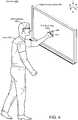
- FIG. 3shows a first use case scenario 300 involving a user 302 wearing an example of pressure sensitive smart ring 202.
- the useris engaging a digital display device 304.
- the digital display deviceincludes a depth sensor 306.
- the depth sensorcan be manifest as a red, green, blue, plus depth (RGBD) camera.
- RGBDplus depth
- Various types of visible light, non-visible light, and/or sonic depth sensors, among otherscan be employed.
- the depth sensor 306can be useful in detecting the presence of user 302 in front of the digital display device 304 and detecting gestures performed by the user in front of the digital display device. However, the depth sensor may not be able to accurately detect user actions close to the digital display device. For instance, the depth sensor may not be able to distinguish whether the user is pointing at a location on the digital display device or touching the location on the digital display device.
- the pressure sensitive smart ring 202can determine whether the user's finger is touching a surface as indicated by 'starburst' 308. Further, the pressure sensitive smart ring 202 can determine that while touching the surface the finger is moving in a downward direction as indicated by arrow 310.
- Data from the depth sensor 306 and the pressure sensitive smart ring 202can detect user gestures in front of the digital display device as well as user contact of the digital display device.
- the pressure sensitive smart ring 202 and the depth sensor 306can collectively provide information that can allow the digital display device to function in a manner similar to a touch sensitive display device without actually being 'touch sensitive.'
- FIG. 4shows another use case scenario 400 that is similar to the use case scenario of FIG. 3 .
- the pressure sensitive smart ring 202can operate cooperatively with smart glasses 402 to provide information about user 302.
- the smart glassescan capture information about what is in front of the user.
- the smart glassescan 'see' content on the digital display device 304.
- the smart glassesmay be less effective at determining whether the user 302 is touching the digital display device 304.
- the pressure sensitive smart ring 202can accurately determine whether the user is touching the digital display device.
- the pressure sensitive smart ring 202 and the smart glasses 402can communicate with the digital display device 304 to detect user gestures (both touch and non-touch) to provide an enhanced interactive experience to the user.
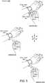
- FIG. 5shows another use case scenario 500 at instance one, instance two, and instance three.
- Scenario 500involves pressure sensitive smart rings 202(1) and 202(2) and a smart watch 502.
- Pressure sensitive smart ring 202(1)is positioned on the user's index finger 104 and pressure sensitive smart ring 202(2) is positioned on the user's middle finger.
- Instance oneshows the user touching the smart watch with his index finger 104. This touch can be detected by pressure sensitive smart ring 202(1).
- This touchcan be interpreted as a first user command, such as to select an application to run on the smart watch.
- Instance twoshows the user performing a non-touch command by bending the index finger 104 at the middle joint.
- This non-touch commandcan be detected by pressure sensitive smart ring 202(1) and distinguished by the smart ring from the command of instance one by a pressure profile (e.g., which pressure sensors detect pressure).
- This commandcould be interpreted as a scroll down command by the smart watch, for example.
- Instance threeshows a similar non-touch command to instance two except that it is performed by both the index finger and the middle finger (e.g. a multi-finger gesture) and detected by pressure sensitive smart ring 202(1) and pressure sensitive smart ring 202(2).
- This commandcould be interpreted as a 'select' command by the smart watch, for example.
- Mechanisms for accomplishing this functionalityare described below relative to FIG. 6 .
- FIG. 6shows a gesture detection system 600.
- system 600includes pressure sensitive smart ring 202, digital display device 304, depth sensor 306, smart glasses 402, smart watch 502, and a smart phone 602. Any of these devices can communicate over one or more networks 604.
- configuration 606(1)represents an operating system centric configuration
- configuration 606(2)represents a system on a chip configuration
- Configuration 606(1)is organized into one or more applications 610, operating system 612, and hardware 614.
- Configuration 606(2)is organized into shared resources 616, dedicated resources 618, and an interface 620 there between.
- the pressure sensitive smart ring 202can include storage 622, a processor 624, a battery 626 (or other power source), a battery charger 628, sensors 630, a communication component 632, and/or a gesture component 634. These elements can be positioned in/on or otherwise associated with a physical finger band 636. For instance, the elements can be positioned within the finger band 636 so that the pressure sensitive smart ring 202 has the general appearance of a traditional 'jewelry' ring.
- the finger band 636can be formed of various materials such as plastics, polymers, and/or natural materials such as jade or other minerals.
- the pressure sensitive smart ring 202can also include ornamental aspects such as precious stones to mimic a traditional jewelry ring.
- any of pressure sensitive smart ring 202, digital display device 304, depth sensor 306, smart glasses 402, smart watch 502, and/or smart phone 602can be thought of as computers.
- the term “device,” “computer,” or “computing device” as used hereincan mean any type of device that has some amount of processing capability and/or storage capability. Processing capability can be provided by one or more processors that can execute data in the form of computer-readable instructions to provide a functionality. Data, such as computer-readable instructions and/or user-related data, can be stored on storage, such as storage that can be internal or external to the computer.
- the storagecan include any one or more of volatile or non-volatile memory, hard drives, flash storage devices, and/or optical storage devices (e.g., CDs, DVDs etc.), remote storage (e.g., cloud-based storage), among others.
- the term “computer-readable media”can include signals.
- Computer-readable storage mediaexcludes signals.
- Computer-readable storage mediaincludes “computer-readable storage devices.” Examples of computer-readable storage devices include volatile storage media, such as RAM, and non-volatile storage media, such as hard drives, optical discs, and/or flash memory, among others.
- configuration 606(2)can be thought of as a system on a chip (SOC) type design.
- SOCsystem on a chip
- functionality provided by the devicecan be integrated on a single SOC or multiple coupled SOCs.
- One or more processorscan be configured to coordinate with shared resources, such as memory, storage, etc., and/or one or more dedicated resources, such as hardware blocks configured to perform certain specific functionality.
- shared resourcessuch as memory, storage, etc.
- dedicated resourcessuch as hardware blocks configured to perform certain specific functionality.
- processoras used herein can also refer to central processing units (CPU), graphical processing units (GPUs), controllers, microcontrollers, processor cores, or other types of processing devices.
- any of the functions described hereincan be implemented using software, firmware, hardware (e.g., fixed-logic circuitry), manual processing, or a combination of these implementations.
- the term "component” as used hereingenerally represents software, firmware, hardware, whole devices or networks, or a combination thereof. In the case of a software implementation, for instance, these may represent program code that performs specified tasks when executed on a processor (e.g., CPU or CPUs).
- the program codecan be stored in one or more computer-readable memory devices, such as computer-readable storage media.
- the features and techniques of the componentare platform-independent, meaning that they may be implemented on a variety of commercial computing platforms having a variety of processing configurations.
- the battery 626can be charged in various ways by the battery charger 628.
- the battery chargeris manifest as a wireless inductive charger.
- the wireless inductive chargercan include multiple conductive coils wrapping around the pressure sensitive smart ring 202, such as following the ring shape of the finger band 636. In other configurations the coils can be associated with the ring but not coiled around the ring. For instance, small coils can be contained within the finger band or otherwise associated with the finger band.
- the wireless inductive chargercan capture magnetic energy from wireless chargers.
- the wireless chargerscan be included in any of digital display device 304, depth sensor 306, smart glasses 402, smart watch 502, smart phone 602, and/or other devices.
- the wireless inductive charging featurecan provide a proximity sensing function for the two devices. For instance, when the user places his hand with the pressure sensitive smart ring 202 near the smart phone 602, the wireless inductive charger can detect the magnetic field of the smart phone and thus indicate to the pressure sensitive smart ring 202 that it is proximate to the smart phone. Similarly, the entry of the pressure sensitive smart ring 202 into the magnetic field generated by the smart phone can indicate to the smart phone that the pressure sensitive smart ring 202 is proximate to the smart phone.
- some pressure sensitive smart ring implementationscan opportunistically harvest energy from an NFC-enabled companion device, such as devices 304, 306, 402, 502, and/or 602, among others for perpetual operation without explicit charging.
- the gesture component 634can manage the sensors 630, battery 626, processor 624, and/or other components to conserve resources. In other configurations a power management controller (not shown) may manage the components. Several techniques for conserving power usage are described below.
- sensors 630can be included in the pressure sensitive smart ring 202.
- the sensorscan include pressure sensors 638.
- three pressure sensorsare illustrated positioned on an inner surface 640 (e.g., inwardly facing surface) of the finger band 636.
- pressure sensor 638(1)is configured to be positioned at the 8-9 o'clock position (with the diamond at the top of the ring acting as 12 o'clock).
- Pressure sensor 638(2)is configured to be positioned at the 6 o'clock position and pressure sensor 638(3) is configured to be positioned at the 3-4 o'clock position.
- other numbers and/or positions of pressure sensorscan be employed.
- a radial array of pressure sensorscould be positioned on the inside surface of the ring so that even if the ring spins on the user's finger, pressure detected by generally opposing pressure sensors can be indicative of a touch gesture.
- pressure sensorscan include force sensitive resistors and/or piezoelectric sensors, among others.
- the pressure sensorcan be coupled to a low power comparator and controlled by power gating as determined by the gesture component 634.
- Sensors 630can also include accelerometers, gyroscopes, magnetometers, and/or microphones, among others.
- the implementation of FIG. 4can include pressure sensors to detect contact with the surface and accelerometers to detect the downward movement.
- the gyroscould further detect 'twisting' of the pressure sensitive smart ring 202 to allow a straight down movement to be distinguished from a down and to the left or a down and to the right gesture.
- motioncan be detected via the microphone as audio signals. Such a configuration can use less power than may be consumed by accelerometers.
- an audio based motion detectorcan have multiple sub modules, such as a microphone with a built-in amplifier and high pass filter, a highpass analog filter to filter out typical environmental noise, an amplifier, a low-pass filter, and an envelope detector.
- the gesture component 634can receive input from the sensors 630.
- the gesture component 634can identify user actions from the sensor input. For instance, assume that the user performs the touch action of instance one of FIG. 5 . In that case, pressure sensors 638(1) and 638(3) of FIG. 6 would detect pressure created by the lateral tendons and pressure sensor 638(2) would not detect pressure.
- the gesture componentcan interpret the output of the three sensors 638(1)-638(3) as a touch gesture. Now assume that the user performs the finger bend gesture of FIG. 5 instance two. In that case, each of sensors, 638(1), 638(2), and 638(3) would detect pressure.
- the gesture componentcan interpret the output of the three sensors 638(1)-638(3) as a non-touch finger bend gesture.
- gesture detectione.g., gesture detection
- the communication component 632can allow the pressure sensitive smart ring 202 to communicate with various devices, such as the illustrated companion devices.
- the communication componentcan include a receiver and a transmitter and/or other radio frequency circuitry for communicating with various technologies, such as cellular, Wi-Fi (IEEE 802.xx), Bluetooth, etc.
- the gesture component 634 on the pressure sensitive ring 202can be relatively robust and perform analysis on signals received from sensors 630 to identify a user action.
- the gesture componentcould then send an indication of the identified user action to a companion device (e.g., any of devices 304, 306, 402, 502, and/or 602) that the pressure sensitive smart ring is operating in cooperation with.
- the pressure sensitive smart ringcould send the signals to the companion device.
- a gesture component (not shown) on the companion devicecould then analyze the sensor signals to identify the user action.
- the pressure sensitive smart ringcould send information to a remote resource, such as cloud based resources for processing.
- sensors 630include force sensitive resistors, accelerometers, and an audio based sensor configured to detect motion of the user's finger on a surface.
- sensors 630include force sensitive resistors, accelerometers, and an audio based sensor configured to detect motion of the user's finger on a surface.
- the usercould wear anywhere from one to ten pressure sensitive smart rings 202 (e.g., one on each finger including thumbs).
- the gesture detection component 634can place the pressure sensitive smart ring 202 in an inactive sleep state to prevent accidental interpretation of day-to-day user activities as gestures.
- the ring's accelerometercan be in a low-power autonomous motion-detection state.
- the pressure sensitive smart ring 202can be brought into an active state by tapping the surface four times (or some other unique action). Once in the active state, the pressure sensitive smart ring 202 can enter a touch-detect active state by turning on the touch detection sensor.
- the 1st tapcan help trigger the accelerometer motion detector, while the rest of the taps can be used to reduce accidental triggering of the active state.
- the gesture component 634can collect raw accelerometer readings which can also be buffered during the touch-detect state.
- the touchis detected by the pressure sensors, and the pressure sensitive smart ring 202 can enter motion-detect state.
- the audio-based motion detectorcan be turned on to detect the motion of the finger along the surface.
- processed accelerometer components along a plane of the ringcan be stored (e.g., yz plane).
- the gesture detection component 634can employ a classifier to the accelerometer data to identify the gesture.
- gesture component 634can implement the following four groups of gestures including, tap, swipe, scroll, and written text, which are summarized in Table 1. Of course other gestures are contemplated, especially when the user wears pressure sensitive smart rings on multiple fingers.
- the tap gesturecan satisfy a similar functionality to the typical tap gesture on a touch sensitive surface, or the left mouse click. Similar to touch surfaces and mice, multiple, closely spaced, tap actions can define multiple gestures. For instance, two double-taps can be used to transition between "active" and "inactive” modes as described above.
- the swipe gesturecan be used with primitive touch interfaces for quickly scanning through multiple windows or a collection of items such as photos.
- This implementation of the pressure sensitive smart ring 202can support four different swipe actions which include: swipe-up, swipe-down, swipe-left, and swipe-right.
- Table 1Different gestures, including different modes, and number of classification primitives can be implemented on the pressure sensitive smart ring 202.
- Gesture Modes # primitivesTap down 1 Swipe up, down, left, right 4 Scroll up, down, left, right 6 right-up, left-down Written Text English characters 12
- the scroll actioncan be similar to the touch surface or mouse-based scroll.
- the gesture component 634can identify six scroll actions: scroll-left, scroll-right, scroll-up, scroll-down, scroll-right-up, and scroll-left-down.
- the pressure sensitive smart ring 202can also implement a writing-based English text entry, where the user can simply write the characters on a surface using the index finger.
- the gesture component 634can treat each character as a combination of multiple primitive shapes called "strokes".
- FIG. 7shows examples of stroke gesture primitives 700.
- 12 strokesare used for text entry in this implementation.
- the strokescan include directional and/or rotational movements.
- the gesture componentcan identify these strokes, and can also measure inter-stoke latencies which can help identify strokes belonging to a single character.
- the stroke identifiers and inter-stroke latenciescan be used to identify the individual characters at a remote device.
- size and weight constraintslimit the size of the battery used to power the pressure sensitive smart ring 202.
- a 10mAh battery capacitycan be used to approximate a traditional jewelry type ring. This battery can fit in the crown or the finger band of the pressure sensitive smart ring 202.
- the pressure sensitive smart ring 202can use the subcarrier based NFC energy harvesting approach to passively recharge the ring battery while the user is holding the smart phone 602 next to the ring.
- the smart ringhas a coil loop wound around the ring finger band. Winding the coil around the ring finger band can enable a large (and potentially maximum) loop size to achieve better energy harvesting.
- This implementationcan use a combination of two techniques to detect the motion of the user's finger on a surface.
- the pressure sensorcan detect the finger touching a surface by sensing the pressure imparted by a lateral tendon of the finger; while an energy-efficient audio sensor can detect the movement of the finger on the surface by listening to the audio signal generated by the friction between the finger and the surface.
- the gesture component 634can interpret the acoustic signals generated due to the friction when the finger moves across the surface to detect finger motion on the surface.
- the amount of audio energy emitted from the finger / surface interactionis a function of the speed of finger motion and the physical properties of the surface.
- Some implementationscan offer enhanced surface detection using pressure and audio-based techniques. For instance, a combination of tendon pressure and audio based techniques can be analyzed to provide efficient and reliable surface detection due to the complementary characteristics of these techniques.
- the tendon pressure-based techniquecan consume an order of magnitude less power than the audio-based solution, however, unlike the audio based solution, the pressure-based technique tends not to be able to identify finger motion directly. Accelerometers offer another solution, but at the potential cost of extra processing overhead and segmentation errors that can severely affect the system performance.
- the audio-solutioncan detect both motion and touch during motion. However, the audio-based solution can be affected by ambient audio noise-induced errors. Bandpass filtering can remove a significant portion of these errors.
- the touch detectorcan prevent the accidental triggering of motion sensing due to errors that are not filtered.
- the touch detectorcan also prevent cascading failures by touch-based gating of the gesture detection in the presence of noise.
- the gesture component 634can utilize classifiers for identifying the gesture primitives. For instance, gesture primitives can be categorized based on starting dynamics, real-timeliness, and context dependency of interpretation.
- Hard landing gesturesstart with the user's finger landing on the surface at a relatively high velocity. Both taps and swipes can be hard landing gestures. Soft landing gestures can start with the finger meeting the surface at a low velocity. Both scroll gestures and strokes for text entry can be soft landing gestures.
- the scroll gesturescan entail real-time identification, since the user tends to desire continuous feedback on the current scroll position. Due to short interaction time, both tap and swipe gestures can be identified in non-real-time after the gesture has been completed.
- the strokes for text entrycan also be identified in non-real-time, at the end of each stroke to improve classification accuracy. This is acceptable since the high-level symbols, such as characters, can only be interpreted after collecting all strokes that make up the character, due to lack of absolute position.
- Context free gesturesare gestures that can be interpreted on the pressure sensitive smart ring 202 without the knowledge of the user interface (UI) element the user is interacting with. Both tapping and swiping gestures belong to this category.
- Context dependent gesturescan utilize knowledge of the current UI element type for correct interpretation by the pressure sensitive smart ring 202. Some of the stroke and scroll gestures that look identical can be interpreted differently due to different real-time needs. To enable proper interpretation of these, the gesture component 634 can operate on the presumption that the remote device informs the pressure sensitive smart ring 202 when the user starts and stops interacting with a text entry area.
- the pressure sensitive smart ring 202's gesture component 634can use the accelerometer data to identify different gestures on a surface. When gestures are performed on a surface, the signature of the gesture tends to be captured in the acceleration components that are parallel to the surface of interaction. Since the pressure sensitive smart ring 202, when worn on the finger, does not stay parallel to the interaction surface, and since individual users' frames of reference will differ from one another, the gesture component can convert the (x,y,z) components of the accelerometer to the (x,y,z) components with respect to the interacting plane. Some implementations can assume a horizontal plane of interaction, which is true for most of the interaction surfaces available in the environment. Other implementations can handle the interaction on an arbitrarily inclined plane.
- the gesture component 634can use the gravity acceleration vector just prior to movement of the finger to determine the inclination of the finger to the plane, since this angle can vary across users and instances.
- Some implementations of the gesture component 634can use a two-level classification scheme for gesture classification.
- the top-level classifiercalled the landing classifier
- the landing classifiercan be invoked to classify the event as either a soft landing event or a hard landing event.
- the gesture component 634can evaluate the output of the landing classifier and the UI context reported by the companion device (e.g., the device the user is engaging). The gesture component 634 can then invoke one of the low level classifiers - swipe-tap, stroke, or scroll.
- the gesture component 634can also invoke the swipe-tap classifier to handle a hard landing.
- This classifiercan use the surface touch duration - determined by the length of the audio envelope, and the accelerometer samples to classify the event as either a tap gesture or one of the four swipe gestures.
- the gesture component 634can invoke the stroke classifier. Since there can be multiple consecutive strokes during a single touch, for example when writing L character, accelerometer data collected after the soft landing can be segmented based on the audio envelope. These segmented data can be fed to the stroke classifier to classify the stroke to one of the 12 possible strokes. This process can continue until the finger leaves the surface.
- the gesture component 634can invoke the scroll classifier.
- the scroll classifiercan first detect a short 'nudge' at the start of the scroll based on the audio envelope, and can classify the data collected between the touch event and the end of the nudge to determine the type of scroll event. After this classification stage, the smart ring periodically can transmit 'in-scroll' messages to the companion device to provide real-time information on the continued scroll event until the finger stops moving and leaves the surface.
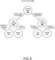
- FIG. 8shows a state diagram 800 of how different classification stages can be invoked in some implementations. The rest of this section describes these classification stages in more detail.
- the gesture component 634( FIG. 6 ) can classify hard landings versus soft landings by exploiting this activity on the accelerometer z-axis at the beginning of a gesture entry.
- n samplescan be evaluated surrounding the start of motion. These n samples may be used as the input to a heuristic, threshold-based classification or as the input to an SVM classifier.
- the z-axis magnitudecan be compared to a threshold.
- a magnitude below the thresholdcan indicate a soft landing 804.
- a magnitude that is equal to or above the thresholdcan indicate a hard landing 806.
- the swipe-tap classifiercan be invoked after detecting a hard landing 806.
- a duration envelope of the contact of the finger across the surfacecan be compared to a duration threshold.
- a duration envelope that is less than the duration thresholdcan indicate a tap event 808.
- a duration that is longer than the duration thresholdcan indicate a swipe event 810.
- a tap gesturecan be identified solely from the envelope information, while identification of a swipe can entail further classification.
- the soft landingcan be evaluated to distinguish a scroll 812 from a stroke 814.
- An SVM classifiercan be utilized to classify strokes.
- the SVM classifiercan use the x, y, and z axis accelerometer readings as the feature vector. Since the stroke duration can vary at different instances as well as across users, a sample, such as 100 points can be linearly interpolated across each x and y axis sample for a given gesture. A fixed number of averages can be computed across these interpolated points for each axis. This set of averages can then be passed to the SVM classifier.
- Scroll classificationcan happen after a stroke is detected based on the context of the remote user interface (e.g., the companion device that the user is engaging).
- a short gesturecalled a 'nudge'
- the SVM classifiercan be detected and classified using the SVM classifier to determine the start of one of the six possible scroll gestures.
- Some implementationscan utilize a relatively small number of (such as six) different scroll gestures to ease classification of the scroll action with only a small number of samples.
- the length of the envelopecan provide real-time information to the remote device on the progress of the scroll action.
- the activity of the platformcan be driven by the accelerometer.
- the accelerometercan autonomously collect samples at ⁇ 400Hz (for example) and can interrupt the microcontroller when a new sample is available.
- the sampled datacan be buffered for landing type estimation, the microcontroller interrupt service routine (ISR) also can check the status of the touch detector.
- ISRmicrocontroller interrupt service routine
- the pressure sensitive smart ring 202can transition to touch-process mode.
- the audio-based motion detector outputcan be sampled at ⁇ 100Hz with processor ADC (at every 4th ISR).
- processor ADCat every 4th ISR.
- the pressure sensitive smart ring 202can start accumulating coordinate-aligned accelerometer data.
- the appropriate classifiercan be invoked, and the results can be transmitted over the radio (e.g., communication component 632), such as by using a best effort transmission scheme.
- an SVM classifiercan be employed for gesture classification.
- the SVM classifiercan be a multi-class linear-kernel SVM classifier.
- the SVM classifiercan use pair-wise classification, entailing n ( n - 1)/ pair-wise classifiers to classify n classes.
- Each ( F ( i ) X , F ( i ) Y ) feature tuplecan be calculated by first breaking all the ( x, y ) acceleration data in to four buckets, and then averaging the data in each bucket.
- the x and y acceleration component of each data samplecan be computed immediately after reading ( x, y, z ) acceleration data sample from the accelerometer.
- some implementationscan employ running averages of each n samples of data to be calculated. Value n can be selected such that there are at most 60 computed averages for the worst case duration of each gesture class. Once the gesture ends, these pre-computed averages can be broken into four equal-size buckets to compute the four feature tuples.
- wireless chargingcan be achieved via magnetic fields generated by a companion device, such as smart phone 602.
- a companion devicesuch as smart phone 602.
- Some implementationscan be configured so that the charging occurs efficiently (potentially maximally) when the user holds the smart phone in a natural manner with the ring bearing hand.
- At least some of the present implementationscan offer a low-power wearable smart ring that can enable users to enter gestures by interacting on arbitrary surfaces.
- the smart ringcan use energy efficient finger-tendon based touch detection and audio-based motion detection to capture user interaction instances.
- a lightweight mufti-classifier solutionaccurately classifies different gesture primitives. In one case, using a 10 mAh battery powered by energy harvested from an NFC-enabled smart phone, the ring can support more than 10 hours of active user interactions.
- FIG. 9illustrates a flowchart of a method or technique 900 that is consistent with at least some implementations of the present concepts.
- the methodcan obtain signals reflecting pressure of a tendon of a user's finger on a ring positioned on the finger.
- the methodcan interpret the signals to identify an action performed by the finger.
- the methodcan be performed on the ring by a processor or microcontroller.
- the signalscan be sent from the ring to another device, such as a companion device that is proximate to the ring and is working cooperatively with the ring.
- the companion devicecan then perform the interpreting.
- Some implementationscan involve a single user wearing multiple rings. In such a case, each ring can communicate its signals to the companion device (e.g., with a different ring identifier with the signals). The companion device can then interpret actions relating to a single finger or multiple fingers (e.g., multi-finger gestures).
- the usermay have waved a single finger to invoke a specific user command or the user could have waved all the fingers of the hand to invoke a different user command.
- the smart ringmay contain other sensors that sense other parameters. Signals from the other sensors can be interpreted in combination with signals from the pressure sensors to identify the user action.
- sensors on other devicesmay provide signals that can be utilized in combination with the sensed signals to identify the user action. Examples of such scenarios are illustrated relative to FIGS. 3-5 where the digital display 304, the depth sensor 306, the smart glasses 402, and/or the smart watch 502 may sense the user and provide data that is useful in combination with the pressure data.
- multiple usersmay be performing actions and each user may be wearing one or more smart rings.
- the methodcan be implemented in any suitable hardware, software, firmware, or combination thereof, such that a computing device can implement the method (e.g., computer-implemented method).
- the methodis stored on a computer-readable storage media as a set of instructions such that execution by a processor of a computing device causes the computing device to perform the method.
- the present implementationscan derive useful information about user actions from pressure sensors on a smart ring worn on a user's finger.
- the described methods or processescan be performed by the systems and/or devices described above, and/or by other devices and/or systems.
- the order in which the methods are describedis not intended to be construed as a limitation, and any number of the described acts can be combined in any order to implement the method, or an alternate method.
- the methodcan be implemented in any suitable hardware, software, firmware, or combination thereof, such that a device can implement the method.
- the methodis stored on computer-readable storage media as a set of instructions such that execution by a processor of a computing device causes the computing device to perform the method.
Landscapes
- Engineering & Computer Science (AREA)
- Theoretical Computer Science (AREA)
- General Engineering & Computer Science (AREA)
- Human Computer Interaction (AREA)
- Physics & Mathematics (AREA)
- General Physics & Mathematics (AREA)
- Computer Hardware Design (AREA)
- User Interface Of Digital Computer (AREA)
Description
- Increasingly users interact with their mobile devices on the go. Many users continuously utilize various device applications. For instance, users listen to music on mobile devices while traveling, and constantly check E-mails. Shoppers browse through their shopping lists and do price comparisons while shopping, among others.
- Interacting with mobile devices on-the-go tends to require the user to enter different gestures to scroll, zoom, flip, and/or enter text on graphical user interface (GUI) elements. The smart phone with its relatively large display has provided a unified and convenient platform for such interactions. However, more recent trends in wearable devices such as glasses, wrist bands, and watches have made such interactions limited and awkward due to the lack of touch real estate and the positioning of the device itself.
- While mobile device interfaces continue to shrink, interfaces of remote display devices such as TVs and game consoles are becoming even more complex, requiring extensive maneuvering via simple remote controllers or requiring remote control with full keyboard-like capability. For example, with a conventional remote control, a simple task such as entering text to search for a movie title becomes a monumental task leading to a poor user experience.
US20130135223 discloses devices for wearing on fingers, and systems which include said devices.WO2011055326 discloses a human, user interface device and method for interpreting gestures of the hand and wrist, including sensors for sensing the gestures and a data processor for converting the sensed gesture into digital data and outputting the data to a destination device.US20100302137 discloses a system that includes a receiver component that receives gesture data from a sensor unit that is coupled to a body of a gloveless user.- There is provided a device according to
independent claim 1 and a method according to independent claim 10. The present invention is defined by the independent claims. Further aspects of the invention are defined in the dependent claims. Embodiments which do not fall within the scope of the claims do not describe part of the present invention. The description relates to smart rings. One example can include a finger band configured to accommodate a user's finger. This example can also include a set of pressure sensors positioned on an inner surface of the finger band and configured to sense changes to tendons of the user's finger as pressure differentials and to output associated signals. The example can further include a gesture component configured to interpret the signals from the set of pressure sensors to identify individual actions performed by the user's finger. - The above listed example is intended to provide a quick reference to aid the reader and is not intended to define the scope of the concepts described herein.
- The accompanying drawings illustrate implementations of the concepts conveyed in the present document. Features of the illustrated implementations can be more readily understood by reference to the following description taken in conjunction with the accompanying drawings. Like reference numbers in the various drawings are used wherever feasible to indicate like elements. Further, the left-most numeral of each reference number conveys the FIG. and associated discussion where the reference number is first introduced.
FIGS. 1 and 2 collectively show example smart ring applications in accordance with some implementations of the present concepts.FIGS. 3-5 show example smart ring use case scenarios in accordance with some implementations of the present concepts.FIG. 6 shows a system example in accordance with some implementations of the present concepts.FIG. 7 shows stroke gesture primitives that can be utilized in accordance with some implementations of the present concepts.FIG. 8 shows a state diagram that can be utilized in accordance with some implementations of the present concepts.FIG. 9 shows an example flow chart in accordance with some implementations of the present concepts.- The present concepts relate to allowing a user to use his/her fingers to control a device. The implementations relate to a wearable ring platform (e.g., smart ring) worn on one or more of the user's fingers. (As used herein, the term 'finger' can include the 'thumb'). The smart ring can detect and interpret various control gestures or actions performed by the user. The smart ring can wirelessly transmit the control gestures to the device. As used herein any action that can be performed by one or more fingers can be thought of as a gesture. Thus, the action of touching a surface with the finger can be an example of a gesture. Similarly, touching and sliding the finger on a surface can be a gesture. Moving the finger in the air or bending the finger can be a gesture. Further, the action of waving with one or more fingers can be a gesture. Actions performed by both hands can also be a gesture. In summary, actions can include touch gestures and non-touch gestures and/or single finger gestures and multi-finger gestures. Further examples of actions (e.g., gestures) are described below.
- Introductory
FIGS. 1-2 show ahuman hand 100. Most of the hand is covered withskin 102. However, for purposes of explanation, the skin is not shown for a portion of the hand relating to theindex finger 104 to allow visualization of the underlying tissues. More specifically,tendons 106 are visible on the index finger. These tendons can move when the finger moves or when the finger imparts a force on a surface.FIG. 2 introduces a pressure sensitive smart ring (or 'smart ring device' or 'smart ring') 202 positioned on the user's index finger. The pressure sensitive smart ring can include elements for detecting changes to the tendons. Examples of these elements are discussed in more detail below relative toFIG. 6 . (Note that to avoid clutter on the drawing page, onFIG. 2 , thetendon 106 lead line only goes to one of the tendons rather than two inFIG. 1 ). FIG. 3 shows a firstuse case scenario 300 involving a user 302 wearing an example of pressure sensitivesmart ring 202. In this case the user is engaging adigital display device 304. In this example, the digital display device includes adepth sensor 306. In some implementations the depth sensor can be manifest as a red, green, blue, plus depth (RGBD) camera. Various types of visible light, non-visible light, and/or sonic depth sensors, among others can be employed.- The
depth sensor 306 can be useful in detecting the presence of user 302 in front of thedigital display device 304 and detecting gestures performed by the user in front of the digital display device. However, the depth sensor may not be able to accurately detect user actions close to the digital display device. For instance, the depth sensor may not be able to distinguish whether the user is pointing at a location on the digital display device or touching the location on the digital display device. The pressure sensitivesmart ring 202 can determine whether the user's finger is touching a surface as indicated by 'starburst' 308. Further, the pressure sensitivesmart ring 202 can determine that while touching the surface the finger is moving in a downward direction as indicated byarrow 310. Data from thedepth sensor 306 and the pressure sensitivesmart ring 202 can detect user gestures in front of the digital display device as well as user contact of the digital display device. Thus, the pressure sensitivesmart ring 202 and thedepth sensor 306 can collectively provide information that can allow the digital display device to function in a manner similar to a touch sensitive display device without actually being 'touch sensitive.' FIG. 4 shows anotheruse case scenario 400 that is similar to the use case scenario ofFIG. 3 . In this case, the pressure sensitivesmart ring 202 can operate cooperatively withsmart glasses 402 to provide information about user 302. For instance, the smart glasses can capture information about what is in front of the user. In this example, the smart glasses can 'see' content on thedigital display device 304. The smart glasses may be less effective at determining whether the user 302 is touching thedigital display device 304. However, as explained above relative toFIG. 3 , the pressure sensitivesmart ring 202 can accurately determine whether the user is touching the digital display device. The pressure sensitivesmart ring 202 and thesmart glasses 402 can communicate with thedigital display device 304 to detect user gestures (both touch and non-touch) to provide an enhanced interactive experience to the user.FIG. 5 shows anotheruse case scenario 500 at instance one, instance two, and instance three.Scenario 500 involves pressure sensitive smart rings 202(1) and 202(2) and asmart watch 502. Pressure sensitive smart ring 202(1) is positioned on the user'sindex finger 104 and pressure sensitive smart ring 202(2) is positioned on the user's middle finger. Instance one shows the user touching the smart watch with hisindex finger 104. This touch can be detected by pressure sensitive smart ring 202(1). This touch can be interpreted as a first user command, such as to select an application to run on the smart watch.- Instance two shows the user performing a non-touch command by bending the
index finger 104 at the middle joint. This non-touch command can be detected by pressure sensitive smart ring 202(1) and distinguished by the smart ring from the command of instance one by a pressure profile (e.g., which pressure sensors detect pressure). This command could be interpreted as a scroll down command by the smart watch, for example. - Instance three shows a similar non-touch command to instance two except that it is performed by both the index finger and the middle finger (e.g. a multi-finger gesture) and detected by pressure sensitive smart ring 202(1) and pressure sensitive smart ring 202(2). This command could be interpreted as a 'select' command by the smart watch, for example. Mechanisms for accomplishing this functionality are described below relative to
FIG. 6 . FIG. 6 shows agesture detection system 600. For purposes of explanation,system 600 includes pressure sensitivesmart ring 202,digital display device 304,depth sensor 306,smart glasses 402,smart watch 502, and asmart phone 602. Any of these devices can communicate over one ormore networks 604.- Two configurations 606(1) and 606(2) are illustrated for pressure sensitive
smart ring 202. Briefly, configuration 606(1) represents an operating system centric configuration and configuration 606(2) represents a system on a chip configuration. Configuration 606(1) is organized into one or more applications 610,operating system 612, andhardware 614. Configuration 606(2) is organized into sharedresources 616, dedicated resources 618, and aninterface 620 there between. - In either configuration, the pressure sensitive
smart ring 202 can includestorage 622, aprocessor 624, a battery 626 (or other power source), abattery charger 628,sensors 630, acommunication component 632, and/or agesture component 634. These elements can be positioned in/on or otherwise associated with aphysical finger band 636. For instance, the elements can be positioned within thefinger band 636 so that the pressure sensitivesmart ring 202 has the general appearance of a traditional 'jewelry' ring. Thefinger band 636 can be formed of various materials such as plastics, polymers, and/or natural materials such as jade or other minerals. The pressure sensitivesmart ring 202 can also include ornamental aspects such as precious stones to mimic a traditional jewelry ring. - From one perspective, any of pressure sensitive
smart ring 202,digital display device 304,depth sensor 306,smart glasses 402,smart watch 502, and/orsmart phone 602 can be thought of as computers. - The term "device," "computer," or "computing device" as used herein can mean any type of device that has some amount of processing capability and/or storage capability. Processing capability can be provided by one or more processors that can execute data in the form of computer-readable instructions to provide a functionality. Data, such as computer-readable instructions and/or user-related data, can be stored on storage, such as storage that can be internal or external to the computer. The storage can include any one or more of volatile or non-volatile memory, hard drives, flash storage devices, and/or optical storage devices (e.g., CDs, DVDs etc.), remote storage (e.g., cloud-based storage), among others. As used herein, the term "computer-readable media" can include signals. In contrast, the term "computer-readable storage media" excludes signals. Computer-readable storage media includes "computer-readable storage devices." Examples of computer-readable storage devices include volatile storage media, such as RAM, and non-volatile storage media, such as hard drives, optical discs, and/or flash memory, among others.
- As mentioned above, configuration 606(2) can be thought of as a system on a chip (SOC) type design. In such a case, functionality provided by the device can be integrated on a single SOC or multiple coupled SOCs. One or more processors can be configured to coordinate with shared resources, such as memory, storage, etc., and/or one or more dedicated resources, such as hardware blocks configured to perform certain specific functionality. Thus, the term "processor" as used herein can also refer to central processing units (CPU), graphical processing units (GPUs), controllers, microcontrollers, processor cores, or other types of processing devices.
- Generally, any of the functions described herein can be implemented using software, firmware, hardware (e.g., fixed-logic circuitry), manual processing, or a combination of these implementations. The term "component" as used herein generally represents software, firmware, hardware, whole devices or networks, or a combination thereof. In the case of a software implementation, for instance, these may represent program code that performs specified tasks when executed on a processor (e.g., CPU or CPUs). The program code can be stored in one or more computer-readable memory devices, such as computer-readable storage media. The features and techniques of the component are platform-independent, meaning that they may be implemented on a variety of commercial computing platforms having a variety of processing configurations.
- The
battery 626 can be charged in various ways by thebattery charger 628. In one instance, the battery charger is manifest as a wireless inductive charger. The wireless inductive charger can include multiple conductive coils wrapping around the pressure sensitivesmart ring 202, such as following the ring shape of thefinger band 636. In other configurations the coils can be associated with the ring but not coiled around the ring. For instance, small coils can be contained within the finger band or otherwise associated with the finger band. The wireless inductive charger can capture magnetic energy from wireless chargers. The wireless chargers can be included in any ofdigital display device 304,depth sensor 306,smart glasses 402,smart watch 502,smart phone 602, and/or other devices. Beyond the charging facet, the wireless inductive charging feature can provide a proximity sensing function for the two devices. For instance, when the user places his hand with the pressure sensitivesmart ring 202 near thesmart phone 602, the wireless inductive charger can detect the magnetic field of the smart phone and thus indicate to the pressure sensitivesmart ring 202 that it is proximate to the smart phone. Similarly, the entry of the pressure sensitivesmart ring 202 into the magnetic field generated by the smart phone can indicate to the smart phone that the pressure sensitivesmart ring 202 is proximate to the smart phone. In summary, some pressure sensitive smart ring implementations can opportunistically harvest energy from an NFC-enabled companion device, such asdevices - Further, powering sensors and analyzing sensor data consumes power. The
gesture component 634 can manage thesensors 630,battery 626,processor 624, and/or other components to conserve resources. In other configurations a power management controller (not shown) may manage the components. Several techniques for conserving power usage are described below. - Multiple types of
sensors 630 can be included in the pressure sensitivesmart ring 202. Of course, the sensors can includepressure sensors 638. In this example, three pressure sensors are illustrated positioned on an inner surface 640 (e.g., inwardly facing surface) of thefinger band 636. In this case, when the pressure sensitivesmart ring 202 is worn by the user, pressure sensor 638(1) is configured to be positioned at the 8-9 o'clock position (with the diamond at the top of the ring acting as 12 o'clock). Pressure sensor 638(2) is configured to be positioned at the 6 o'clock position and pressure sensor 638(3) is configured to be positioned at the 3-4 o'clock position. Of course, other numbers and/or positions of pressure sensors can be employed. For example, a radial array of pressure sensors could be positioned on the inside surface of the ring so that even if the ring spins on the user's finger, pressure detected by generally opposing pressure sensors can be indicative of a touch gesture. Examples of pressure sensors can include force sensitive resistors and/or piezoelectric sensors, among others. In some cases the pressure sensor can be coupled to a low power comparator and controlled by power gating as determined by thegesture component 634. Sensors 630 can also include accelerometers, gyroscopes, magnetometers, and/or microphones, among others. For instance, the implementation ofFIG. 4 can include pressure sensors to detect contact with the surface and accelerometers to detect the downward movement. While not shown inFIG. 4 , the gyros could further detect 'twisting' of the pressure sensitivesmart ring 202 to allow a straight down movement to be distinguished from a down and to the left or a down and to the right gesture. In another configuration, motion can be detected via the microphone as audio signals. Such a configuration can use less power than may be consumed by accelerometers.- In one such implementation an audio based motion detector can have multiple sub modules, such as a microphone with a built-in amplifier and high pass filter, a highpass analog filter to filter out typical environmental noise, an amplifier, a low-pass filter, and an envelope detector.
- The
gesture component 634 can receive input from thesensors 630. Thegesture component 634 can identify user actions from the sensor input. For instance, assume that the user performs the touch action of instance one ofFIG. 5 . In that case, pressure sensors 638(1) and 638(3) ofFIG. 6 would detect pressure created by the lateral tendons and pressure sensor 638(2) would not detect pressure. The gesture component can interpret the output of the three sensors 638(1)-638(3) as a touch gesture. Now assume that the user performs the finger bend gesture ofFIG. 5 instance two. In that case, each of sensors, 638(1), 638(2), and 638(3) would detect pressure. The gesture component can interpret the output of the three sensors 638(1)-638(3) as a non-touch finger bend gesture. - Other action detection (e.g., gesture detection) scenarios that involve identification of tapping, swiping, scrolling, and stroking for hand written text entry are described below.
- The
communication component 632 can allow the pressure sensitivesmart ring 202 to communicate with various devices, such as the illustrated companion devices. The communication component can include a receiver and a transmitter and/or other radio frequency circuitry for communicating with various technologies, such as cellular, Wi-Fi (IEEE 802.xx), Bluetooth, etc. - Note that in some cases the
gesture component 634 on the pressuresensitive ring 202 can be relatively robust and perform analysis on signals received fromsensors 630 to identify a user action. The gesture component could then send an indication of the identified user action to a companion device (e.g., any ofdevices - The discussion below provides further details on specific implementations of the pressure sensitive
smart ring 202. For purposes of explanation, in this discussionsmart phone 602 operates as a companion device to the pressure sensitivesmart ring 202. In this case,sensors 630 include force sensitive resistors, accelerometers, and an audio based sensor configured to detect motion of the user's finger on a surface. In this discussion, only a single pressure sensitivesmart ring 202 is employed, but as noted above, the user could wear anywhere from one to ten pressure sensitive smart rings 202 (e.g., one on each finger including thumbs). - To conserve energy, the
gesture detection component 634 can place the pressure sensitivesmart ring 202 in an inactive sleep state to prevent accidental interpretation of day-to-day user activities as gestures. In this state, the ring's accelerometer can be in a low-power autonomous motion-detection state. - When the user is ready to enter gestures on an available surface, the pressure sensitive
smart ring 202 can be brought into an active state by tapping the surface four times (or some other unique action). Once in the active state, the pressure sensitivesmart ring 202 can enter a touch-detect active state by turning on the touch detection sensor. The 1st tap can help trigger the accelerometer motion detector, while the rest of the taps can be used to reduce accidental triggering of the active state. Thegesture component 634 can collect raw accelerometer readings which can also be buffered during the touch-detect state. - When the user touches the surface to enter a gesture, the touch is detected by the pressure sensors, and the pressure sensitive
smart ring 202 can enter motion-detect state. In the motion-detect state, the audio-based motion detector can be turned on to detect the motion of the finger along the surface. During this state, processed accelerometer components along a plane of the ring can be stored (e.g., yz plane). At the end of motion or the touch, thegesture detection component 634 can employ a classifier to the accelerometer data to identify the gesture. - This implementation of the
gesture component 634 can implement the following four groups of gestures including, tap, swipe, scroll, and written text, which are summarized in Table 1. Of course other gestures are contemplated, especially when the user wears pressure sensitive smart rings on multiple fingers. - Tap. The tap gesture can satisfy a similar functionality to the typical tap gesture on a touch sensitive surface, or the left mouse click. Similar to touch surfaces and mice, multiple, closely spaced, tap actions can define multiple gestures. For instance, two double-taps can be used to transition between "active" and "inactive" modes as described above.
- Swipe. The swipe gesture can be used with primitive touch interfaces for quickly scanning through multiple windows or a collection of items such as photos. This implementation of the pressure sensitive
smart ring 202 can support four different swipe actions which include: swipe-up, swipe-down, swipe-left, and swipe-right.Table 1: Different gestures, including different modes, and number of classification primitives can be implemented on the pressure sensitive smart ring 202.Gesture Modes # primitives Tap down 1 Swipe up, down, left, right 4 Scroll up, down, left, right 6 right-up, left-down Written Text English characters 12 - Scroll. The scroll action can be similar to the touch surface or mouse-based scroll. The
gesture component 634 can identify six scroll actions: scroll-left, scroll-right, scroll-up, scroll-down, scroll-right-up, and scroll-left-down. - Writing-based text entry. The pressure sensitive
smart ring 202 can also implement a writing-based English text entry, where the user can simply write the characters on a surface using the index finger. - The
gesture component 634 can treat each character as a combination of multiple primitive shapes called "strokes".FIG. 7 shows examples ofstroke gesture primitives 700. In this example, 12 strokes are used for text entry in this implementation. The strokes can include directional and/or rotational movements. The gesture component can identify these strokes, and can also measure inter-stoke latencies which can help identify strokes belonging to a single character. The stroke identifiers and inter-stroke latencies can be used to identify the individual characters at a remote device. - In this implementation, size and weight constraints limit the size of the battery used to power the pressure sensitive
smart ring 202. In one case, a 10mAh battery capacity can be used to approximate a traditional jewelry type ring. This battery can fit in the crown or the finger band of the pressure sensitivesmart ring 202. - This relatively small 10mAh battery capacity may cause the user to recharge the battery several times within a day, which would potentially be a large obstacle to the usability of the platform. To overcome this limitation, the pressure sensitive
smart ring 202 can use the subcarrier based NFC energy harvesting approach to passively recharge the ring battery while the user is holding thesmart phone 602 next to the ring. - To harvest energy from an NFC enabled antenna, the smart ring has a coil loop wound around the ring finger band. Winding the coil around the ring finger band can enable a large (and potentially maximum) loop size to achieve better energy harvesting.
- This implementation can use a combination of two techniques to detect the motion of the user's finger on a surface. As mentioned above, the pressure sensor can detect the finger touching a surface by sensing the pressure imparted by a lateral tendon of the finger; while an energy-efficient audio sensor can detect the movement of the finger on the surface by listening to the audio signal generated by the friction between the finger and the surface.
- More specifically, the
gesture component 634 can interpret the acoustic signals generated due to the friction when the finger moves across the surface to detect finger motion on the surface. - The amount of audio energy emitted from the finger / surface interaction is a function of the speed of finger motion and the physical properties of the surface.
- Some implementations can offer enhanced surface detection using pressure and audio-based techniques. For instance, a combination of tendon pressure and audio based techniques can be analyzed to provide efficient and reliable surface detection due to the complementary characteristics of these techniques.
- The tendon pressure-based technique can consume an order of magnitude less power than the audio-based solution, however, unlike the audio based solution, the pressure-based technique tends not to be able to identify finger motion directly. Accelerometers offer another solution, but at the potential cost of extra processing overhead and segmentation errors that can severely affect the system performance.
- The audio-solution can detect both motion and touch during motion. However, the audio-based solution can be affected by ambient audio noise-induced errors. Bandpass filtering can remove a significant portion of these errors. The touch detector can prevent the accidental triggering of motion sensing due to errors that are not filtered. The touch detector can also prevent cascading failures by touch-based gating of the gesture detection in the presence of noise.
- In some implementations the
gesture component 634 can utilize classifiers for identifying the gesture primitives. For instance, gesture primitives can be categorized based on starting dynamics, real-timeliness, and context dependency of interpretation. - Hard landing gestures start with the user's finger landing on the surface at a relatively high velocity. Both taps and swipes can be hard landing gestures. Soft landing gestures can start with the finger meeting the surface at a low velocity. Both scroll gestures and strokes for text entry can be soft landing gestures.
- The scroll gestures can entail real-time identification, since the user tends to desire continuous feedback on the current scroll position. Due to short interaction time, both tap and swipe gestures can be identified in non-real-time after the gesture has been completed. The strokes for text entry can also be identified in non-real-time, at the end of each stroke to improve classification accuracy. This is acceptable since the high-level symbols, such as characters, can only be interpreted after collecting all strokes that make up the character, due to lack of absolute position.
- Context free gestures are gestures that can be interpreted on the pressure sensitive
smart ring 202 without the knowledge of the user interface (UI) element the user is interacting with. Both tapping and swiping gestures belong to this category. - Context dependent gestures can utilize knowledge of the current UI element type for correct interpretation by the pressure sensitive
smart ring 202. Some of the stroke and scroll gestures that look identical can be interpreted differently due to different real-time needs. To enable proper interpretation of these, thegesture component 634 can operate on the presumption that the remote device informs the pressure sensitivesmart ring 202 when the user starts and stops interacting with a text entry area. - The pressure sensitive
smart ring 202'sgesture component 634 can use the accelerometer data to identify different gestures on a surface. When gestures are performed on a surface, the signature of the gesture tends to be captured in the acceleration components that are parallel to the surface of interaction. Since the pressure sensitivesmart ring 202, when worn on the finger, does not stay parallel to the interaction surface, and since individual users' frames of reference will differ from one another, the gesture component can convert the (x,y,z) components of the accelerometer to the (x,y,z) components with respect to the interacting plane. Some implementations can assume a horizontal plane of interaction, which is true for most of the interaction surfaces available in the environment. Other implementations can handle the interaction on an arbitrarily inclined plane. - For computing the components along the interacting plane, the
gesture component 634 can use the gravity acceleration vector just prior to movement of the finger to determine the inclination of the finger to the plane, since this angle can vary across users and instances. - To perform this normalization, the
gesture component 634 can compute two angles: pitch (θ) and roll (φ). These angles can be computed according to the following equations:

- After computing these angles while the finger is stationary, they can be applied to subsequent accelerometer samples to compensate for finger orientation while the finger is moving:


- There are two limitations to correcting for the finger angle in this way. First, some implementations can operate on the assumption that these angles do not change during a gesture - if this assumption is violated, the gravity vector may pollute the x and y components, and a fraction of the x and y accelerations will be falsely attributed to the z axis. Second, some implementations do not correct for a third orientation angle, yaw (ψ), if gyros are not utilized (gravity vector provides no information as to how the finger twists in a plane perpendicular to gravity). Thus, these implementations can leverage the assumption that the user's finger motion will be perpendicular to their body and the impact ofψ is negligible. If this assumption is violated, the x and y acceleration components may not be properly separated. While worth noting, neither of these limitations tends to have a significant impact on classification accuracy.
- Some implementations of the
gesture component 634 can use a two-level classification scheme for gesture classification. When the pressure sensors indicate a touch event, the top-level classifier, called the landing classifier, can be invoked to classify the event as either a soft landing event or a hard landing event. Thegesture component 634 can evaluate the output of the landing classifier and the UI context reported by the companion device (e.g., the device the user is engaging). Thegesture component 634 can then invoke one of the low level classifiers - swipe-tap, stroke, or scroll. - The
gesture component 634 can also invoke the swipe-tap classifier to handle a hard landing. This classifier can use the surface touch duration - determined by the length of the audio envelope, and the accelerometer samples to classify the event as either a tap gesture or one of the four swipe gestures. - For a soft landing, if the context reports text input, the
gesture component 634 can invoke the stroke classifier. Since there can be multiple consecutive strokes during a single touch, for example when writingL character, accelerometer data collected after the soft landing can be segmented based on the audio envelope. These segmented data can be fed to the stroke classifier to classify the stroke to one of the 12 possible strokes. This process can continue until the finger leaves the surface. - For a soft landing with a non-text input context, the
gesture component 634 can invoke the scroll classifier. The scroll classifier can first detect a short 'nudge' at the start of the scroll based on the audio envelope, and can classify the data collected between the touch event and the end of the nudge to determine the type of scroll event. After this classification stage, the smart ring periodically can transmit 'in-scroll' messages to the companion device to provide real-time information on the continued scroll event until the finger stops moving and leaves the surface. FIG. 8 shows a state diagram 800 of how different classification stages can be invoked in some implementations. The rest of this section describes these classification stages in more detail.- While the finger is moving on a surface, negligible activity on an accelerometer's z-axis is expected. However, when the finger initially lands on the surface, the finger can abruptly stop, causing large magnitude, short-lived spikes induced by the finger's sudden deceleration. The gesture component 634 (
FIG. 6 ) can classify hard landings versus soft landings by exploiting this activity on the accelerometer z-axis at the beginning of a gesture entry. When a surface is initially detected at 802,n samples can be evaluated surrounding the start of motion. Thesen samples may be used as the input to a heuristic, threshold-based classification or as the input to an SVM classifier. The intuition behind the efficacy of each of these approaches is the existence of large, observable deltas in z-axis acceleration. To summarize, the z-axis magnitude can be compared to a threshold. A magnitude below the threshold can indicate a soft landing 804. A magnitude that is equal to or above the threshold can indicate ahard landing 806. - The swipe-tap classifier can be invoked after detecting a
hard landing 806. A duration envelope of the contact of the finger across the surface can be compared to a duration threshold. A duration envelope that is less than the duration threshold can indicate atap event 808. A duration that is longer than the duration threshold can indicate aswipe event 810. - A tap gesture can be identified solely from the envelope information, while identification of a swipe can entail further classification.
- Returning to soft landing 804, the soft landing can be evaluated to distinguish a
scroll 812 from astroke 814. An SVM classifier can be utilized to classify strokes. The SVM classifier can use the x, y, and z axis accelerometer readings as the feature vector. Since the stroke duration can vary at different instances as well as across users, a sample, such as 100 points can be linearly interpolated across each x and y axis sample for a given gesture. A fixed number of averages can be computed across these interpolated points for each axis. This set of averages can then be passed to the SVM classifier. - Scroll classification can happen after a stroke is detected based on the context of the remote user interface (e.g., the companion device that the user is engaging). A short gesture, called a 'nudge', can be detected and classified using the SVM classifier to determine the start of one of the six possible scroll gestures. Some implementations can utilize a relatively small number of (such as six) different scroll gestures to ease classification of the scroll action with only a small number of samples. After the user performs the nudge, the length of the envelope can provide real-time information to the remote device on the progress of the scroll action.
- When the pressure sensitive
smart ring 202 is in the active mode (touch-detect, or touch-process), the activity of the platform can be driven by the accelerometer. The accelerometer can autonomously collect samples at ≃400Hz (for example) and can interrupt the microcontroller when a new sample is available. - During touch-detect, the sampled data can be buffered for landing type estimation, the microcontroller interrupt service routine (ISR) also can check the status of the touch detector.
- If touch is active, the pressure sensitive
smart ring 202 can transition to touch-process mode. In this mode, the audio-based motion detector output can be sampled at ≃100Hz with processor ADC (at every 4th ISR). Once motion is detected - determined by the change of audio envelope by a preset threshold-the pressure sensitivesmart ring 202 can start accumulating coordinate-aligned accelerometer data. At the end of the motion, the appropriate classifier can be invoked, and the results can be transmitted over the radio (e.g., communication component 632), such as by using a best effort transmission scheme. - As introduced above, an SVM classifier can be employed for gesture classification. The SVM classifier can be a multi-class linear-kernel SVM classifier. The SVM classifier can use pair-wise classification, entailingn(n - 1)/ pair-wise classifiers to classifyn classes.
- Some implementations can use four features for eachx andy axis, resulting in eight SVM features. Each (F(i)X, F(i)Y) feature tuple can be calculated by first breaking all the (x, y) acceleration data in to four buckets, and then averaging the data in each bucket. Thex andy acceleration component of each data sample can be computed immediately after reading (x, y, z) acceleration data sample from the accelerometer.
- Due to limited RAM size, instead of buffering data at 400 Hz until the end of a gesture, some implementations can employ running averages of eachn samples of data to be calculated. Valuen can be selected such that there are at most 60 computed averages for the worst case duration of each gesture class. Once the gesture ends, these pre-computed averages can be broken into four equal-size buckets to compute the four feature tuples.
- As mentioned above, wireless charging can be achieved via magnetic fields generated by a companion device, such as
smart phone 602. Some implementations can be configured so that the charging occurs efficiently (potentially maximally) when the user holds the smart phone in a natural manner with the ring bearing hand. - In summary, at least some of the present implementations can offer a low-power wearable smart ring that can enable users to enter gestures by interacting on arbitrary surfaces. The smart ring can use energy efficient finger-tendon based touch detection and audio-based motion detection to capture user interaction instances. A lightweight mufti-classifier solution accurately classifies different gesture primitives. In one case, using a 10 mAh battery powered by energy harvested from an NFC-enabled smart phone, the ring can support more than 10 hours of active user interactions.
FIG. 9 illustrates a flowchart of a method ortechnique 900 that is consistent with at least some implementations of the present concepts.- At
block 902, the method can obtain signals reflecting pressure of a tendon of a user's finger on a ring positioned on the finger. - At
block 904, the method can interpret the signals to identify an action performed by the finger. - In some cases, the method can be performed on the ring by a processor or microcontroller. In other cases, the signals can be sent from the ring to another device, such as a companion device that is proximate to the ring and is working cooperatively with the ring. The companion device can then perform the interpreting. Some implementations can involve a single user wearing multiple rings. In such a case, each ring can communicate its signals to the companion device (e.g., with a different ring identifier with the signals). The companion device can then interpret actions relating to a single finger or multiple fingers (e.g., multi-finger gestures). For instance, the user may have waved a single finger to invoke a specific user command or the user could have waved all the fingers of the hand to invoke a different user command. In some cases, the smart ring may contain other sensors that sense other parameters. Signals from the other sensors can be interpreted in combination with signals from the pressure sensors to identify the user action. In still other cases, sensors on other devices may provide signals that can be utilized in combination with the sensed signals to identify the user action. Examples of such scenarios are illustrated relative to
FIGS. 3-5 where thedigital display 304, thedepth sensor 306, thesmart glasses 402, and/or thesmart watch 502 may sense the user and provide data that is useful in combination with the pressure data. Also, in some cases, such as a digital whiteboard scenario, multiple users may be performing actions and each user may be wearing one or more smart rings. - The order in which the above methods are described is not intended to be construed as a limitation, and any number of the described blocks can be combined in any order to implement the method, or an alternate method. Furthermore, the method can be implemented in any suitable hardware, software, firmware, or combination thereof, such that a computing device can implement the method (e.g., computer-implemented method). In one case, the method is stored on a computer-readable storage media as a set of instructions such that execution by a processor of a computing device causes the computing device to perform the method.
- In summary, the present implementations can derive useful information about user actions from pressure sensors on a smart ring worn on a user's finger.
- The described methods or processes can be performed by the systems and/or devices described above, and/or by other devices and/or systems. The order in which the methods are described is not intended to be construed as a limitation, and any number of the described acts can be combined in any order to implement the method, or an alternate method. Furthermore, the method can be implemented in any suitable hardware, software, firmware, or combination thereof, such that a device can implement the method. In one case, the method is stored on computer-readable storage media as a set of instructions such that execution by a processor of a computing device causes the computing device to perform the method.
- Although techniques, methods, devices, systems, etc., pertaining to detecting user actions are described in language specific to structural features and/or methodological acts, it is to be understood that the subject matter defined in the appended claims is not necessarily limited to the specific features or acts described. Rather, the specific features and acts are disclosed as exemplary forms of implementing the claimed methods, devices, systems, etc.


Claims (15)
- A smart ring device (202), comprising:a finger band (636) configured to accommodate a user's finger (104);at least one pressure sensor (638) secured to the finger band (636) in a manner that can detect pressure imparted by tendons (106) passing through the finger band (636) during performance of actions by the finger (104), wherein the at least one pressure sensor is configured to detect the finger touching a surface by sensing the pressure imparted by a lateral tendon of the finger; and,a gesture component (634) configured to analyze signals from the at least one pressure sensor (638) to identify an individual action performed by the finger (104).
- The smart ring device (202) of claim 1, further comprising a battery (626) and a wireless charger (628) for the battery contained in the finger band (636).
- The smart ring device (202) of claim 2, wherein the wireless charger comprises conductive coils, wherein the conductive coils are wrapped around the finger band (636) or wherein the conductive coils are associated with the finger band (636) but do not wrap around the finger band (636).
- The smart ring device (202) of claim 1, wherein the at least one pressure sensor (638) comprises an array of pressure sensors (638) radially distributed around an inner surface of the finger band (636).
- The smart ring device (202) of claim 1, wherein the pressure sensor (638) comprises a force sensitive resistor or a piezoelectric sensor.
- The smart ring device (202) of claim 1, further comprising motion detectors.
- The smart ring device (202) of claim 6, wherein the motion detectors comprise audio sensors or accelerometers.
- The smart ring device (202) of claim 1, further comprising a communication component to communicate an indication of the individual action to a companion device.
- The smart ring device (202) of claim 8, wherein the communication component comprises a Bluetooth transmitter.
- A computer implemented method, comprising:obtaining signals from at least one pressure sensor reflecting pressure of a lateral tendon (106) of a user's finger (104) on a ring positioned on the finger (104); and,interpreting the signals to identify an action performed by the finger (104) wherein the action is the finger touching a surface.
- The method of claim 10, wherein the interpreting is performed by the ring.
- The method of claim 10, wherein the obtaining signals comprises obtaining the signals from the ring at a companion device and wherein the companion device performs the interpreting.
- The method of claim 12, wherein the companion device obtains signals from multiple rings positioned on different fingers of the user, and wherein the interpreting comprises identifying a multi-finger gesture performed by the user.
- The method of claim 12, wherein the companion device comprises a smart phone (602), a smart watch (502), smart glasses (402), or a display device (304).
- The method of claim 10, further comprising obtaining additional signals relating to movement of the finger (104) during the action and wherein the interpreting comprises interpreting the signals and the additional signals to identify the action.
Applications Claiming Priority (2)
| Application Number | Priority Date | Filing Date | Title |
|---|---|---|---|
| US14/286,910US9594427B2 (en) | 2014-05-23 | 2014-05-23 | Finger tracking |
| PCT/US2015/031290WO2015179262A1 (en) | 2014-05-23 | 2015-05-18 | Finger tracking |
Publications (2)
| Publication Number | Publication Date |
|---|---|
| EP3146410A1 EP3146410A1 (en) | 2017-03-29 |
| EP3146410B1true EP3146410B1 (en) | 2019-10-16 |
Family
ID=53373573
Family Applications (1)
| Application Number | Title | Priority Date | Filing Date |
|---|---|---|---|
| EP15728263.3AActiveEP3146410B1 (en) | 2014-05-23 | 2015-05-18 | Finger tracking |
Country Status (5)
| Country | Link |
|---|---|
| US (3) | US9594427B2 (en) |
| EP (1) | EP3146410B1 (en) |
| KR (1) | KR102366112B1 (en) |
| CN (1) | CN106462239B (en) |
| WO (1) | WO2015179262A1 (en) |
Families Citing this family (78)
| Publication number | Priority date | Publication date | Assignee | Title |
|---|---|---|---|---|
| US9891718B2 (en) | 2015-04-22 | 2018-02-13 | Medibotics Llc | Devices for measuring finger motion and recognizing hand gestures |
| US9594427B2 (en) | 2014-05-23 | 2017-03-14 | Microsoft Technology Licensing, Llc | Finger tracking |
| KR101524575B1 (en)* | 2014-08-20 | 2015-06-03 | 박준호 | Wearable device |
| US9582076B2 (en) | 2014-09-17 | 2017-02-28 | Microsoft Technology Licensing, Llc | Smart ring |
| WO2016060461A1 (en) | 2014-10-15 | 2016-04-21 | Jun Ho Park | Wearable device |
| US9619049B2 (en)* | 2015-02-18 | 2017-04-11 | International Business Machines Corporation | One-handed operation of mobile electronic devices |
| US9921651B2 (en)* | 2015-04-29 | 2018-03-20 | International Business Machines Company | Video display for visually impaired people |
| US9887591B2 (en) | 2015-05-13 | 2018-02-06 | International Business Machines Corporation | Electric ring with external power source |
| CN104978142B (en)* | 2015-06-17 | 2018-07-31 | 华为技术有限公司 | A kind of control method of intelligent wearable device and intelligent wearable device |
| WO2017010305A1 (en) | 2015-07-15 | 2017-01-19 | 日本電気株式会社 | Authentication device, authentication system, authentication method, and program |
| US11003246B2 (en) | 2015-07-22 | 2021-05-11 | Mentor Acquisition One, Llc | External user interface for head worn computing |
| KR20170028130A (en) | 2015-09-03 | 2017-03-13 | 박준호 | Wearable device |
| US10915220B2 (en) | 2015-10-14 | 2021-02-09 | Maxell, Ltd. | Input terminal device and operation input method |
| US10599919B2 (en)* | 2015-12-31 | 2020-03-24 | Microsoft Technology Licensing, Llc | Detection of hand gestures using gesture language discrete values |
| US10579216B2 (en) | 2016-03-28 | 2020-03-03 | Microsoft Technology Licensing, Llc | Applications for multi-touch input detection |
| KR102490518B1 (en)* | 2016-05-19 | 2023-01-20 | 하만인터내셔날인더스트리스인코포레이티드 | Gesture-activated audio device with visible feedback |
| WO2018006291A1 (en)* | 2016-07-06 | 2018-01-11 | 华为技术有限公司 | Interaction device, system and method |
| US10878771B2 (en) | 2016-07-13 | 2020-12-29 | Motorola Mobility Llc | Deformable electronic device and methods and systems for display remediation to compensate performance degradation |
| US10372892B2 (en) | 2016-07-13 | 2019-08-06 | Motorola Mobility Llc | Electronic device with gesture actuation of companion devices, and corresponding systems and methods |
| US10251056B2 (en)* | 2016-07-13 | 2019-04-02 | Motorola Mobility Llc | Electronic device with gesture actuation of companion devices, and corresponding systems and methods |
| US11243567B2 (en) | 2016-07-13 | 2022-02-08 | Motorola Mobility Llc | Deformable electronic device and methods and systems for reconfiguring presentation data and actuation elements |
| US9716779B1 (en)* | 2016-08-31 | 2017-07-25 | Maxine Nicodemus | Wireless communication system |
| US10095342B2 (en) | 2016-11-14 | 2018-10-09 | Google Llc | Apparatus for sensing user input |
| EP3340031B1 (en)* | 2016-12-21 | 2021-09-15 | Nxp B.V. | Motion detection circuits, and associated methods |
| EP3538975B1 (en)* | 2017-02-17 | 2023-01-04 | Samsung Electronics Co., Ltd. | Electronic device and methods for determining orientation of the device |
| US10001808B1 (en)* | 2017-03-29 | 2018-06-19 | Google Llc | Mobile device accessory equipped to communicate with mobile device |
| US10013081B1 (en) | 2017-04-04 | 2018-07-03 | Google Llc | Electronic circuit and method to account for strain gauge variation |
| US11749093B2 (en) | 2017-04-05 | 2023-09-05 | Microsensor Labs, LLC | System and method for predicting hygiene opportunity and hygiene actions for hygiene protocols |
| US11257350B2 (en) | 2017-04-05 | 2022-02-22 | Microsensor Labs, LLC | System and method for opportunity-based reminding or compliance with one or more health protocols |
| CA3056803A1 (en)* | 2017-04-05 | 2018-10-11 | Microsensor Labs, LLC | System and method for proximity sensing of movable portions of a premises |
| US10679488B2 (en) | 2017-04-05 | 2020-06-09 | Microsensor Labs, LLC | System and method for improving compliance with one or more protocols including hand hygiene and personal protective equipment protocols |
| US10635255B2 (en) | 2017-04-18 | 2020-04-28 | Google Llc | Electronic device response to force-sensitive interface |
| US10514797B2 (en) | 2017-04-18 | 2019-12-24 | Google Llc | Force-sensitive user input interface for an electronic device |
| WO2018223397A1 (en) | 2017-06-09 | 2018-12-13 | Microsoft Technology Licensing, Llc. | Wearable device enabling multi-finger gestures |
| CN107329574A (en)* | 2017-06-30 | 2017-11-07 | 联想(北京)有限公司 | Input method and system for electronic equipment |
| CN111565637A (en)* | 2017-10-09 | 2020-08-21 | 钛深科技 | Human body action and position sensing, identification and analysis based on wearable pressure sensor array |
| US10955974B2 (en) | 2017-12-19 | 2021-03-23 | Google Llc | Wearable electronic devices having an inward facing input device and methods of use thereof |
| US11614793B2 (en)* | 2018-02-28 | 2023-03-28 | Logitech Europe S.A. | Precision tracking of user interaction with a virtual input device |
| US10878231B2 (en)* | 2018-05-10 | 2020-12-29 | International Business Machines Corporation | Writing recognition using wearable pressure sensing device |
| US11073898B2 (en)* | 2018-09-28 | 2021-07-27 | Apple Inc. | IMU for touch detection |
| US11949673B1 (en) | 2019-07-23 | 2024-04-02 | BlueOwl, LLC | Gesture authentication using a smart ring |
| US12126181B2 (en) | 2019-07-23 | 2024-10-22 | Quanata, Llc | Energy harvesting circuits for a smart ring |
| US12067093B2 (en) | 2019-07-23 | 2024-08-20 | Quanata, Llc | Biometric authentication using a smart ring |
| US11551644B1 (en) | 2019-07-23 | 2023-01-10 | BlueOwl, LLC | Electronic ink display for smart ring |
| US11853030B2 (en) | 2019-07-23 | 2023-12-26 | BlueOwl, LLC | Soft smart ring and method of manufacture |
| US11537203B2 (en) | 2019-07-23 | 2022-12-27 | BlueOwl, LLC | Projection system for smart ring visual output |
| US11594128B2 (en) | 2019-07-23 | 2023-02-28 | BlueOwl, LLC | Non-visual outputs for a smart ring |
| US11984742B2 (en)* | 2019-07-23 | 2024-05-14 | BlueOwl, LLC | Smart ring power and charging |
| US12077193B1 (en) | 2019-07-23 | 2024-09-03 | Quanata, Llc | Smart ring system for monitoring sleep patterns and using machine learning techniques to predict high risk driving behavior |
| US11909238B1 (en) | 2019-07-23 | 2024-02-20 | BlueOwl, LLC | Environment-integrated smart ring charger |
| US11637511B2 (en) | 2019-07-23 | 2023-04-25 | BlueOwl, LLC | Harvesting energy for a smart ring via piezoelectric charging |
| US11462107B1 (en) | 2019-07-23 | 2022-10-04 | BlueOwl, LLC | Light emitting diodes and diode arrays for smart ring visual output |
| US11479258B1 (en) | 2019-07-23 | 2022-10-25 | BlueOwl, LLC | Smart ring system for monitoring UVB exposure levels and using machine learning technique to predict high risk driving behavior |
| US11093262B2 (en) | 2019-07-29 | 2021-08-17 | Motorola Mobility Llc | Electronic devices and corresponding methods for switching between normal and privacy modes of operation |
| US11113375B2 (en) | 2019-09-09 | 2021-09-07 | Motorola Mobility Llc | Electronic devices with proximity authentication and gaze actuation of companion electronic devices and corresponding methods |
| WO2021061275A1 (en)* | 2019-09-24 | 2021-04-01 | Arkh, Llc | Smart ring |
| US11580300B1 (en) | 2019-09-29 | 2023-02-14 | Snap Inc. | Ring motion capture and message composition system |
| JP7246390B2 (en) | 2019-12-19 | 2023-03-27 | グーグル エルエルシー | Direct manipulation of display devices using wearable computing devices |
| US11237632B2 (en)* | 2020-03-03 | 2022-02-01 | Finch Technologies Ltd. | Ring device having an antenna, a touch pad, and/or a charging pad to control a computing device based on user motions |
| US12416967B2 (en) | 2020-03-16 | 2025-09-16 | Arkh, Inc. | Spatially aware computing hub and environment |
| US11755111B2 (en) | 2020-03-16 | 2023-09-12 | Arkh, Inc. | Spatially aware computing hub and environment |
| US11762202B1 (en) | 2020-03-31 | 2023-09-19 | Snap Inc. | Ring-mounted flexible circuit remote control |
| US11573644B2 (en)* | 2020-04-21 | 2023-02-07 | Hyundai Mobis Co., Ltd. | Apparatus and method for recognizing gesture |
| US11502713B2 (en) | 2020-09-16 | 2022-11-15 | Genki Instruments ehf. | Smart ring |
| US20220407550A1 (en)* | 2020-09-16 | 2022-12-22 | Genki Instruments ehf. | Smart ring |
| CN117222971A (en)* | 2020-09-22 | 2023-12-12 | 苹果公司 | Multi-finger gestures based on finger manipulation data and limb tracking data |
| CN114356069B (en)* | 2020-10-13 | 2025-01-14 | Oppo广东移动通信有限公司 | Interaction method, device, equipment and storage medium |
| KR20220087104A (en)* | 2020-12-17 | 2022-06-24 | 삼성전자주식회사 | Wearable device and method for detecting motion gesture of the wearable device |
| WO2022153032A1 (en)* | 2021-01-14 | 2022-07-21 | Sportrax Technology Ltd | Wearable remote controller |
| US11532958B2 (en) | 2021-02-18 | 2022-12-20 | Google Llc | Predictive wireless charging of electronic devices |
| CN113093911B (en)* | 2021-04-09 | 2023-06-30 | 浙江大学 | Intelligent ring oriented to three-dimensional interactive input and interaction method thereof |
| KR20220167978A (en) | 2021-06-15 | 2022-12-22 | 삼성전자주식회사 | Wearable device and control method thereof |
| CN115793842A (en)* | 2021-09-09 | 2023-03-14 | 北京有竹居网络技术有限公司 | Ring-type electronic device, terminal control method, electronic apparatus, and storage medium |
| US12436620B2 (en)* | 2022-08-18 | 2025-10-07 | Meta Platforms Technologies, Llc | Multi-stage gestures detected based on neuromuscular-signal sensors of a wearable device to activate user-interface interactions with low-false positive rates, and systems and methods of use thereof |
| US12360608B2 (en) | 2022-08-18 | 2025-07-15 | Meta Platforms Technologies, Llc | Navigating a user interface using in-air gestures detected via neuromuscular-signal sensors of a wearable device, and systems and methods of use thereof |
| WO2024042502A1 (en) | 2022-08-26 | 2024-02-29 | Genki Instrument Ehf. | Improved smart ring |
| USD1065542S1 (en) | 2023-10-23 | 2025-03-04 | Lotus Laboratories Inc. | Device and system controlling ring |
| US20250006043A1 (en)* | 2024-08-13 | 2025-01-02 | Faisal Alothainah | Wearable Device for Wireless Control of External Systems |
Citations (2)
| Publication number | Priority date | Publication date | Assignee | Title |
|---|---|---|---|---|
| US5832296A (en)* | 1995-04-26 | 1998-11-03 | Interval Research Corp. | Wearable context sensitive user interface for interacting with plurality of electronic devices of interest to the user |
| US20090251407A1 (en)* | 2008-04-03 | 2009-10-08 | Microsoft Corporation | Device interaction with combination of rings |
Family Cites Families (90)
| Publication number | Priority date | Publication date | Assignee | Title |
|---|---|---|---|---|
| US6882128B1 (en) | 2000-09-27 | 2005-04-19 | Science Applications International Corporation | Method and system for energy reclamation and reuse |
| US20030142065A1 (en) | 2002-01-28 | 2003-07-31 | Kourosh Pahlavan | Ring pointer device with inertial sensors |
| US20030214481A1 (en) | 2002-05-14 | 2003-11-20 | Yongming Xiong | Finger worn and operated input device and method of use |
| JP4119187B2 (en) | 2002-07-17 | 2008-07-16 | 国立大学法人金沢大学 | Input device |
| KR100634494B1 (en) | 2002-08-19 | 2006-10-16 | 삼성전기주식회사 | Wearable information input device, information processing device and information input method |
| US7042438B2 (en) | 2003-09-06 | 2006-05-09 | Mcrae Michael William | Hand manipulated data apparatus for computers and video games |
| US20060001646A1 (en) | 2004-07-02 | 2006-01-05 | Wei Hai | Finger worn and operated input device |
| EP1785808B1 (en) | 2005-11-10 | 2014-10-01 | BlackBerry Limited | System and method for activating an electronic device |
| US8559987B1 (en) | 2005-12-31 | 2013-10-15 | Blaze Mobile, Inc. | Wireless bidirectional communications between a mobile device and associated secure element |
| US8879986B2 (en) | 2005-12-31 | 2014-11-04 | Michelle Fisher | Wireless bidirectional communications between a mobile device and associated secure element using inaudible sound waves |
| US8615374B1 (en) | 2006-06-09 | 2013-12-24 | Rockwell Automation Technologies, Inc. | Modular, configurable, intelligent sensor system |
| US7702282B2 (en) | 2006-07-13 | 2010-04-20 | Sony Ericsoon Mobile Communications Ab | Conveying commands to a mobile terminal through body actions |
| US20090278798A1 (en) | 2006-07-26 | 2009-11-12 | The Research Foundation Of The State University Of New York | Active Fingertip-Mounted Object Digitizer |
| KR101299682B1 (en) | 2006-10-16 | 2013-08-22 | 삼성전자주식회사 | Universal input device |
| US8665225B2 (en)* | 2007-01-07 | 2014-03-04 | Apple Inc. | Portable multifunction device, method, and graphical user interface for interpreting a finger gesture |
| US8033916B2 (en) | 2007-05-04 | 2011-10-11 | Theodore Caldwell | Grip pressure sensor |
| EP2191458A4 (en)* | 2007-08-19 | 2012-02-15 | Ringbow Ltd | Finger-worn devices and related methods of use |
| US8031172B2 (en)* | 2007-10-12 | 2011-10-04 | Immersion Corporation | Method and apparatus for wearable remote interface device |
| US9135620B2 (en) | 2008-02-08 | 2015-09-15 | Microsoft Technology Licensing, Llc | Mobile device security using wearable security tokens |
| TWI374391B (en) | 2008-05-27 | 2012-10-11 | Ind Tech Res Inst | Method for recognizing writing motion and trajectory and apparatus for writing and recognizing system |
| US8447704B2 (en) | 2008-06-26 | 2013-05-21 | Microsoft Corporation | Recognizing gestures from forearm EMG signals |
| US8106749B2 (en) | 2008-07-14 | 2012-01-31 | Sony Ericsson Mobile Communications Ab | Touchless control of a control device |
| KR100920252B1 (en) | 2008-11-07 | 2009-10-05 | 서창수 | Mouse controlled by finger movement in the air |
| US8581856B2 (en) | 2009-05-27 | 2013-11-12 | Microsoft Corporation | Touch sensitive display apparatus using sensor input |
| US8112066B2 (en) | 2009-06-22 | 2012-02-07 | Mourad Ben Ayed | System for NFC authentication based on BLUETOOTH proximity |
| JP4988016B2 (en) | 2009-08-27 | 2012-08-01 | 韓國電子通信研究院 | Finger motion detection apparatus and method |
| EP2302882A1 (en) | 2009-09-24 | 2011-03-30 | Research In Motion Limited | Communication device and method for initiating NFC communication |
| US8717291B2 (en) | 2009-10-07 | 2014-05-06 | AFA Micro Co. | Motion sensitive gesture device |
| WO2011055326A1 (en) | 2009-11-04 | 2011-05-12 | Igal Firsov | Universal input/output human user interface |
| WO2011070554A2 (en)* | 2009-12-13 | 2011-06-16 | Ringbow Ltd. | Finger-worn input devices and methods of use |
| US8526880B2 (en) | 2010-02-26 | 2013-09-03 | Blackberry Limited | Communications device responsive to near field communications (NFC) to enter locked or unlocked operating modes |
| US8964298B2 (en) | 2010-02-28 | 2015-02-24 | Microsoft Corporation | Video display modification based on sensor input for a see-through near-to-eye display |
| US20140063055A1 (en)* | 2010-02-28 | 2014-03-06 | Osterhout Group, Inc. | Ar glasses specific user interface and control interface based on a connected external device type |
| WO2011106797A1 (en) | 2010-02-28 | 2011-09-01 | Osterhout Group, Inc. | Projection triggering through an external marker in an augmented reality eyepiece |
| US20120206485A1 (en) | 2010-02-28 | 2012-08-16 | Osterhout Group, Inc. | Ar glasses with event and sensor triggered user movement control of ar eyepiece facilities |
| KR20130101975A (en) | 2010-04-16 | 2013-09-16 | 니콜라스 제이 마스탄드리아 | Wearable motion sensing computing interface |
| US8797146B2 (en) | 2010-04-27 | 2014-08-05 | Apple Inc. | Autonomous battery-free microwave frequency communication system |
| US8500031B2 (en) | 2010-07-29 | 2013-08-06 | Bank Of America Corporation | Wearable article having point of sale payment functionality |
| US20120038652A1 (en) | 2010-08-12 | 2012-02-16 | Palm, Inc. | Accepting motion-based character input on mobile computing devices |
| US20120075173A1 (en) | 2010-09-23 | 2012-03-29 | Nokia Corporation | Apparatus and method for user input |
| US20120075196A1 (en)* | 2010-09-23 | 2012-03-29 | Nokia Corporation | Apparatus and method for user input |
| US20120083205A1 (en) | 2010-10-04 | 2012-04-05 | Qualcomm Incorporated | Nfc device having a differential input envelope detector |
| US20120139708A1 (en)* | 2010-12-06 | 2012-06-07 | Massachusetts Institute Of Technology | Wireless Hand Gesture Capture |
| US8572764B2 (en) | 2010-12-09 | 2013-11-05 | Dieter Thellmann | Exercising glove |
| US8811896B2 (en) | 2011-01-07 | 2014-08-19 | Texas Instruments Incorporated | Non-volatile memory for contactless systems |
| US10061387B2 (en)* | 2011-03-31 | 2018-08-28 | Nokia Technologies Oy | Method and apparatus for providing user interfaces |
| US20120256860A1 (en)* | 2011-04-05 | 2012-10-11 | James Robert Justice | Directional Finger Recognition Authoring |
| US20120309354A1 (en) | 2011-06-06 | 2012-12-06 | Syracuse University | Situation aware security system and method for mobile devices |
| US8548380B2 (en) | 2011-06-10 | 2013-10-01 | Broadcom Corporation | Communications device for intelligently routing information among multiple user interfaces |
| US8879985B2 (en) | 2011-06-28 | 2014-11-04 | Broadcom Corporation | Memory arbitrator for electronics communications devices |
| US8179604B1 (en) | 2011-07-13 | 2012-05-15 | Google Inc. | Wearable marker for passive interaction |
| US9042571B2 (en) | 2011-07-19 | 2015-05-26 | Dolby Laboratories Licensing Corporation | Method and system for touch gesture detection in response to microphone output |
| CN102955580B (en) | 2011-08-31 | 2017-05-10 | 赛恩倍吉科技顾问(深圳)有限公司 | Mouse and method for simulating touch operation |
| WO2013048469A1 (en) | 2011-09-30 | 2013-04-04 | Intel Corporation | Detection of gesture data segmentation in mobile devices |
| US20130100044A1 (en) | 2011-10-24 | 2013-04-25 | Motorola Mobility, Inc. | Method for Detecting Wake Conditions of a Portable Electronic Device |
| US9385786B2 (en) | 2011-12-14 | 2016-07-05 | Marvell World Trade Ltd. | Method and apparatus for charging a battery in a mobile device through a near field communication (NFC) antenna |
| US10013053B2 (en) | 2012-01-04 | 2018-07-03 | Tobii Ab | System for gaze interaction |
| US8478195B1 (en) | 2012-02-17 | 2013-07-02 | Google Inc. | Two-factor user authentication using near field communication |
| USD705228S1 (en) | 2012-02-23 | 2014-05-20 | Marni Peters | Actuating ring |
| US9389690B2 (en) | 2012-03-01 | 2016-07-12 | Qualcomm Incorporated | Gesture detection based on information from multiple types of sensors |
| US20130260689A1 (en) | 2012-03-30 | 2013-10-03 | Qualcomm Incorporated | Wirelessly Powered Input Device |
| US20130290522A1 (en) | 2012-04-11 | 2013-10-31 | Edward F. Behm, Jr. | Engine, System and Method of Locating a Mobile Device and Reporting on Other Devices Proximately Located Thereto |
| US20140028547A1 (en) | 2012-07-26 | 2014-01-30 | Stmicroelectronics, Inc. | Simple user interface device and chipset implementation combination for consumer interaction with any screen based interface |
| US9235241B2 (en) | 2012-07-29 | 2016-01-12 | Qualcomm Incorporated | Anatomical gestures detection system using radio signals |
| US20140085177A1 (en)* | 2012-09-21 | 2014-03-27 | Nokia Corporation | Method and apparatus for responding to input based upon relative finger position |
| US20140101755A1 (en) | 2012-10-10 | 2014-04-10 | Research In Motion Limited | Mobile wireless communications device providing security features based upon wearable near field communication (nfc) device and related methods |
| US11372536B2 (en) | 2012-11-20 | 2022-06-28 | Samsung Electronics Company, Ltd. | Transition and interaction model for wearable electronic device |
| US10185416B2 (en) | 2012-11-20 | 2019-01-22 | Samsung Electronics Co., Ltd. | User gesture input to wearable electronic device involving movement of device |
| US9477313B2 (en) | 2012-11-20 | 2016-10-25 | Samsung Electronics Co., Ltd. | User gesture input to wearable electronic device involving outward-facing sensor of device |
| US8994827B2 (en)* | 2012-11-20 | 2015-03-31 | Samsung Electronics Co., Ltd | Wearable electronic device |
| US11237719B2 (en) | 2012-11-20 | 2022-02-01 | Samsung Electronics Company, Ltd. | Controlling remote electronic device with wearable electronic device |
| US8820649B2 (en) | 2012-11-20 | 2014-09-02 | Omne Mobile Payments, Inc. | Electronic card with a programmable magnetic stripe |
| US9030446B2 (en) | 2012-11-20 | 2015-05-12 | Samsung Electronics Co., Ltd. | Placement of optical sensor on wearable electronic device |
| US8743052B1 (en) | 2012-11-24 | 2014-06-03 | Eric Jeffrey Keller | Computing interface system |
| TW201426402A (en) | 2012-12-25 | 2014-07-01 | Askey Computer Corp | Ring-type remote control device, scaling control method and tap control method thereof |
| US9112543B2 (en) | 2012-12-27 | 2015-08-18 | Cambridge Silicon Radio Limited | Near field communication devices and methods |
| CN105473021B (en) | 2013-03-15 | 2018-01-19 | 智能专利有限责任公司 | wearable device and related system |
| WO2014144015A2 (en) | 2013-03-15 | 2014-09-18 | Keller Eric Jeffrey | Computing interface system |
| US9696802B2 (en) | 2013-03-20 | 2017-07-04 | Microsoft Technology Licensing, Llc | Short range wireless powered ring for user interaction and sensing |
| US20140308930A1 (en) | 2013-04-12 | 2014-10-16 | Bao Tran | Timely, glanceable information on a wearable device |
| US8742623B1 (en) | 2013-09-16 | 2014-06-03 | Google Inc. | Device with dual power sources |
| US20150078586A1 (en) | 2013-09-16 | 2015-03-19 | Amazon Technologies, Inc. | User input with fingerprint sensor |
| CN103777752A (en)* | 2013-11-02 | 2014-05-07 | 上海威璞电子科技有限公司 | Gesture recognition device based on arm muscle current detection and motion sensor |
| US20150220158A1 (en) | 2014-01-07 | 2015-08-06 | Nod Inc. | Methods and Apparatus for Mapping of Arbitrary Human Motion Within an Arbitrary Space Bounded by a User's Range of Motion |
| US9965761B2 (en) | 2014-01-07 | 2018-05-08 | Nod, Inc. | Methods and apparatus for providing secure identification, payment processing and/or signing using a gesture-based input device |
| JP6524111B2 (en) | 2014-04-01 | 2019-06-05 | アップル インコーポレイテッドApple Inc. | Apparatus and method for ring computing device |
| US9232331B2 (en) | 2014-05-08 | 2016-01-05 | Microsoft Technology Licensing, Llc | Hand-worn device for surface gesture input |
| US9594427B2 (en) | 2014-05-23 | 2017-03-14 | Microsoft Technology Licensing, Llc | Finger tracking |
| KR20160015050A (en) | 2014-07-30 | 2016-02-12 | 엘지전자 주식회사 | Mobile terminal |
| US9582076B2 (en) | 2014-09-17 | 2017-02-28 | Microsoft Technology Licensing, Llc | Smart ring |
- 2014
- 2014-05-23USUS14/286,910patent/US9594427B2/enactiveActive
- 2015
- 2015-05-18EPEP15728263.3Apatent/EP3146410B1/enactiveActive
- 2015-05-18WOPCT/US2015/031290patent/WO2015179262A1/enactiveApplication Filing
- 2015-05-18KRKR1020167036032Apatent/KR102366112B1/enactiveActive
- 2015-05-18CNCN201580024018.8Apatent/CN106462239B/enactiveActive
- 2016
- 2016-07-29USUS15/223,887patent/US10191543B2/enactiveActive
- 2018
- 2018-06-11USUS16/005,056patent/US10359846B2/enactiveActive
Patent Citations (2)
| Publication number | Priority date | Publication date | Assignee | Title |
|---|---|---|---|---|
| US5832296A (en)* | 1995-04-26 | 1998-11-03 | Interval Research Corp. | Wearable context sensitive user interface for interacting with plurality of electronic devices of interest to the user |
| US20090251407A1 (en)* | 2008-04-03 | 2009-10-08 | Microsoft Corporation | Device interaction with combination of rings |
Also Published As
| Publication number | Publication date |
|---|---|
| CN106462239B (en) | 2019-11-12 |
| US9594427B2 (en) | 2017-03-14 |
| US20180292901A1 (en) | 2018-10-11 |
| KR20170008854A (en) | 2017-01-24 |
| US20150338916A1 (en) | 2015-11-26 |
| EP3146410A1 (en) | 2017-03-29 |
| US20160334870A1 (en) | 2016-11-17 |
| KR102366112B1 (en) | 2022-02-21 |
| CN106462239A (en) | 2017-02-22 |
| WO2015179262A1 (en) | 2015-11-26 |
| US10359846B2 (en) | 2019-07-23 |
| US10191543B2 (en) | 2019-01-29 |
Similar Documents
| Publication | Publication Date | Title |
|---|---|---|
| US10359846B2 (en) | Wearable device gesture detection | |
| CN106575150B (en) | Method for recognizing gestures using motion data and wearable computing device | |
| US11231786B1 (en) | Methods and apparatus for using the human body as an input device | |
| KR102489212B1 (en) | Hand-worn device for surface gesture input | |
| Gummeson et al. | An energy harvesting wearable ring platform for gestureinput on surfaces | |
| US9804679B2 (en) | Touchless user interface navigation using gestures | |
| US9513703B2 (en) | Gesture-based waking and control system for wearable devices | |
| KR102319421B1 (en) | Text input on an interactive display | |
| CN104679246B (en) | The Wearable and control method of human hand Roaming control in a kind of interactive interface | |
| US20140073302A1 (en) | Sensor and Context Based Adjustment of the Operation of a Network Controller | |
| EP3289435B1 (en) | User interface control using impact gestures | |
| US11429249B2 (en) | Application program data processing method and device | |
| US20150241985A1 (en) | Methods and Apparatus for Recognition of a Plurality of Gestures Using Roll Pitch Yaw Data | |
| US10747362B2 (en) | Touch device with suppression band | |
| US20170344125A1 (en) | Detection and usability of personal electronic devices for field engineers | |
| US10684694B2 (en) | Extending interactions of a portable electronic device | |
| JPWO2018020792A1 (en) | INFORMATION PROCESSING APPARATUS, INFORMATION PROCESSING METHOD, AND PROGRAM | |
| Zhou et al. | Pre-classification based hidden Markov model for quick and accurate gesture recognition using a finger-worn device | |
| Cheng et al. | Finger-worn device based hand gesture recognition using long short-term memory | |
| CN104615275A (en) | Character input method and device | |
| Farra et al. | Energy-efficient mobile gesture recognition with computation offloading | |
| Guo et al. | Recognizing the Operating Hand from Touchscreen Traces on Smartphones |
Legal Events
| Date | Code | Title | Description |
|---|---|---|---|
| STAA | Information on the status of an ep patent application or granted ep patent | Free format text:STATUS: THE INTERNATIONAL PUBLICATION HAS BEEN MADE | |
| PUAI | Public reference made under article 153(3) epc to a published international application that has entered the european phase | Free format text:ORIGINAL CODE: 0009012 | |
| STAA | Information on the status of an ep patent application or granted ep patent | Free format text:STATUS: REQUEST FOR EXAMINATION WAS MADE | |
| 17P | Request for examination filed | Effective date:20161122 | |
| AK | Designated contracting states | Kind code of ref document:A1 Designated state(s):AL AT BE BG CH CY CZ DE DK EE ES FI FR GB GR HR HU IE IS IT LI LT LU LV MC MK MT NL NO PL PT RO RS SE SI SK SM TR | |
| AX | Request for extension of the european patent | Extension state:BA ME | |
| DAV | Request for validation of the european patent (deleted) | ||
| DAX | Request for extension of the european patent (deleted) | ||
| STAA | Information on the status of an ep patent application or granted ep patent | Free format text:STATUS: EXAMINATION IS IN PROGRESS | |
| 17Q | First examination report despatched | Effective date:20180619 | |
| GRAP | Despatch of communication of intention to grant a patent | Free format text:ORIGINAL CODE: EPIDOSNIGR1 | |
| STAA | Information on the status of an ep patent application or granted ep patent | Free format text:STATUS: GRANT OF PATENT IS INTENDED | |
| INTG | Intention to grant announced | Effective date:20190510 | |
| GRAS | Grant fee paid | Free format text:ORIGINAL CODE: EPIDOSNIGR3 | |
| GRAA | (expected) grant | Free format text:ORIGINAL CODE: 0009210 | |
| STAA | Information on the status of an ep patent application or granted ep patent | Free format text:STATUS: THE PATENT HAS BEEN GRANTED | |
| AK | Designated contracting states | Kind code of ref document:B1 Designated state(s):AL AT BE BG CH CY CZ DE DK EE ES FI FR GB GR HR HU IE IS IT LI LT LU LV MC MK MT NL NO PL PT RO RS SE SI SK SM TR | |
| REG | Reference to a national code | Ref country code:GB Ref legal event code:FG4D | |
| REG | Reference to a national code | Ref country code:DE Ref legal event code:R096 Ref document number:602015039890 Country of ref document:DE Ref country code:CH Ref legal event code:EP | |
| REG | Reference to a national code | Ref country code:IE Ref legal event code:FG4D | |
| REG | Reference to a national code | Ref country code:AT Ref legal event code:REF Ref document number:1191918 Country of ref document:AT Kind code of ref document:T Effective date:20191115 | |
| REG | Reference to a national code | Ref country code:NL Ref legal event code:FP | |
| REG | Reference to a national code | Ref country code:LT Ref legal event code:MG4D | |
| REG | Reference to a national code | Ref country code:AT Ref legal event code:MK05 Ref document number:1191918 Country of ref document:AT Kind code of ref document:T Effective date:20191016 | |
| PG25 | Lapsed in a contracting state [announced via postgrant information from national office to epo] | Ref country code:NO Free format text:LAPSE BECAUSE OF FAILURE TO SUBMIT A TRANSLATION OF THE DESCRIPTION OR TO PAY THE FEE WITHIN THE PRESCRIBED TIME-LIMIT Effective date:20200116 Ref country code:BG Free format text:LAPSE BECAUSE OF FAILURE TO SUBMIT A TRANSLATION OF THE DESCRIPTION OR TO PAY THE FEE WITHIN THE PRESCRIBED TIME-LIMIT Effective date:20200116 Ref country code:FI Free format text:LAPSE BECAUSE OF FAILURE TO SUBMIT A TRANSLATION OF THE DESCRIPTION OR TO PAY THE FEE WITHIN THE PRESCRIBED TIME-LIMIT Effective date:20191016 Ref country code:PT Free format text:LAPSE BECAUSE OF FAILURE TO SUBMIT A TRANSLATION OF THE DESCRIPTION OR TO PAY THE FEE WITHIN THE PRESCRIBED TIME-LIMIT Effective date:20200217 Ref country code:PL Free format text:LAPSE BECAUSE OF FAILURE TO SUBMIT A TRANSLATION OF THE DESCRIPTION OR TO PAY THE FEE WITHIN THE PRESCRIBED TIME-LIMIT Effective date:20191016 Ref country code:GR Free format text:LAPSE BECAUSE OF FAILURE TO SUBMIT A TRANSLATION OF THE DESCRIPTION OR TO PAY THE FEE WITHIN THE PRESCRIBED TIME-LIMIT Effective date:20200117 Ref country code:LV Free format text:LAPSE BECAUSE OF FAILURE TO SUBMIT A TRANSLATION OF THE DESCRIPTION OR TO PAY THE FEE WITHIN THE PRESCRIBED TIME-LIMIT Effective date:20191016 Ref country code:SE Free format text:LAPSE BECAUSE OF FAILURE TO SUBMIT A TRANSLATION OF THE DESCRIPTION OR TO PAY THE FEE WITHIN THE PRESCRIBED TIME-LIMIT Effective date:20191016 Ref country code:AT Free format text:LAPSE BECAUSE OF FAILURE TO SUBMIT A TRANSLATION OF THE DESCRIPTION OR TO PAY THE FEE WITHIN THE PRESCRIBED TIME-LIMIT Effective date:20191016 Ref country code:LT Free format text:LAPSE BECAUSE OF FAILURE TO SUBMIT A TRANSLATION OF THE DESCRIPTION OR TO PAY THE FEE WITHIN THE PRESCRIBED TIME-LIMIT Effective date:20191016 | |
| PG25 | Lapsed in a contracting state [announced via postgrant information from national office to epo] | Ref country code:IS Free format text:LAPSE BECAUSE OF FAILURE TO SUBMIT A TRANSLATION OF THE DESCRIPTION OR TO PAY THE FEE WITHIN THE PRESCRIBED TIME-LIMIT Effective date:20200224 Ref country code:HR Free format text:LAPSE BECAUSE OF FAILURE TO SUBMIT A TRANSLATION OF THE DESCRIPTION OR TO PAY THE FEE WITHIN THE PRESCRIBED TIME-LIMIT Effective date:20191016 Ref country code:RS Free format text:LAPSE BECAUSE OF FAILURE TO SUBMIT A TRANSLATION OF THE DESCRIPTION OR TO PAY THE FEE WITHIN THE PRESCRIBED TIME-LIMIT Effective date:20191016 | |
| PG25 | Lapsed in a contracting state [announced via postgrant information from national office to epo] | Ref country code:AL Free format text:LAPSE BECAUSE OF FAILURE TO SUBMIT A TRANSLATION OF THE DESCRIPTION OR TO PAY THE FEE WITHIN THE PRESCRIBED TIME-LIMIT Effective date:20191016 | |
| REG | Reference to a national code | Ref country code:DE Ref legal event code:R097 Ref document number:602015039890 Country of ref document:DE | |
| PG2D | Information on lapse in contracting state deleted | Ref country code:IS | |
| PG25 | Lapsed in a contracting state [announced via postgrant information from national office to epo] | Ref country code:DK Free format text:LAPSE BECAUSE OF FAILURE TO SUBMIT A TRANSLATION OF THE DESCRIPTION OR TO PAY THE FEE WITHIN THE PRESCRIBED TIME-LIMIT Effective date:20191016 Ref country code:ES Free format text:LAPSE BECAUSE OF FAILURE TO SUBMIT A TRANSLATION OF THE DESCRIPTION OR TO PAY THE FEE WITHIN THE PRESCRIBED TIME-LIMIT Effective date:20191016 Ref country code:EE Free format text:LAPSE BECAUSE OF FAILURE TO SUBMIT A TRANSLATION OF THE DESCRIPTION OR TO PAY THE FEE WITHIN THE PRESCRIBED TIME-LIMIT Effective date:20191016 Ref country code:RO Free format text:LAPSE BECAUSE OF FAILURE TO SUBMIT A TRANSLATION OF THE DESCRIPTION OR TO PAY THE FEE WITHIN THE PRESCRIBED TIME-LIMIT Effective date:20191016 Ref country code:CZ Free format text:LAPSE BECAUSE OF FAILURE TO SUBMIT A TRANSLATION OF THE DESCRIPTION OR TO PAY THE FEE WITHIN THE PRESCRIBED TIME-LIMIT Effective date:20191016 Ref country code:IS Free format text:LAPSE BECAUSE OF FAILURE TO SUBMIT A TRANSLATION OF THE DESCRIPTION OR TO PAY THE FEE WITHIN THE PRESCRIBED TIME-LIMIT Effective date:20200216 | |
| PLBE | No opposition filed within time limit | Free format text:ORIGINAL CODE: 0009261 | |
| STAA | Information on the status of an ep patent application or granted ep patent | Free format text:STATUS: NO OPPOSITION FILED WITHIN TIME LIMIT | |
| PG25 | Lapsed in a contracting state [announced via postgrant information from national office to epo] | Ref country code:IT Free format text:LAPSE BECAUSE OF FAILURE TO SUBMIT A TRANSLATION OF THE DESCRIPTION OR TO PAY THE FEE WITHIN THE PRESCRIBED TIME-LIMIT Effective date:20191016 Ref country code:SM Free format text:LAPSE BECAUSE OF FAILURE TO SUBMIT A TRANSLATION OF THE DESCRIPTION OR TO PAY THE FEE WITHIN THE PRESCRIBED TIME-LIMIT Effective date:20191016 Ref country code:SK Free format text:LAPSE BECAUSE OF FAILURE TO SUBMIT A TRANSLATION OF THE DESCRIPTION OR TO PAY THE FEE WITHIN THE PRESCRIBED TIME-LIMIT Effective date:20191016 | |
| 26N | No opposition filed | Effective date:20200717 | |
| PG25 | Lapsed in a contracting state [announced via postgrant information from national office to epo] | Ref country code:SI Free format text:LAPSE BECAUSE OF FAILURE TO SUBMIT A TRANSLATION OF THE DESCRIPTION OR TO PAY THE FEE WITHIN THE PRESCRIBED TIME-LIMIT Effective date:20191016 | |
| PG25 | Lapsed in a contracting state [announced via postgrant information from national office to epo] | Ref country code:LI Free format text:LAPSE BECAUSE OF NON-PAYMENT OF DUE FEES Effective date:20200531 Ref country code:CH Free format text:LAPSE BECAUSE OF NON-PAYMENT OF DUE FEES Effective date:20200531 Ref country code:MC Free format text:LAPSE BECAUSE OF FAILURE TO SUBMIT A TRANSLATION OF THE DESCRIPTION OR TO PAY THE FEE WITHIN THE PRESCRIBED TIME-LIMIT Effective date:20191016 | |
| REG | Reference to a national code | Ref country code:BE Ref legal event code:MM Effective date:20200531 | |
| PG25 | Lapsed in a contracting state [announced via postgrant information from national office to epo] | Ref country code:LU Free format text:LAPSE BECAUSE OF NON-PAYMENT OF DUE FEES Effective date:20200518 | |
| PG25 | Lapsed in a contracting state [announced via postgrant information from national office to epo] | Ref country code:IE Free format text:LAPSE BECAUSE OF NON-PAYMENT OF DUE FEES Effective date:20200518 | |
| PG25 | Lapsed in a contracting state [announced via postgrant information from national office to epo] | Ref country code:BE Free format text:LAPSE BECAUSE OF NON-PAYMENT OF DUE FEES Effective date:20200531 | |
| PG25 | Lapsed in a contracting state [announced via postgrant information from national office to epo] | Ref country code:TR Free format text:LAPSE BECAUSE OF FAILURE TO SUBMIT A TRANSLATION OF THE DESCRIPTION OR TO PAY THE FEE WITHIN THE PRESCRIBED TIME-LIMIT Effective date:20191016 Ref country code:MT Free format text:LAPSE BECAUSE OF FAILURE TO SUBMIT A TRANSLATION OF THE DESCRIPTION OR TO PAY THE FEE WITHIN THE PRESCRIBED TIME-LIMIT Effective date:20191016 Ref country code:CY Free format text:LAPSE BECAUSE OF FAILURE TO SUBMIT A TRANSLATION OF THE DESCRIPTION OR TO PAY THE FEE WITHIN THE PRESCRIBED TIME-LIMIT Effective date:20191016 | |
| PG25 | Lapsed in a contracting state [announced via postgrant information from national office to epo] | Ref country code:MK Free format text:LAPSE BECAUSE OF FAILURE TO SUBMIT A TRANSLATION OF THE DESCRIPTION OR TO PAY THE FEE WITHIN THE PRESCRIBED TIME-LIMIT Effective date:20191016 | |
| P01 | Opt-out of the competence of the unified patent court (upc) registered | Effective date:20230501 | |
| PGFP | Annual fee paid to national office [announced via postgrant information from national office to epo] | Ref country code:NL Payment date:20240418 Year of fee payment:10 | |
| PGFP | Annual fee paid to national office [announced via postgrant information from national office to epo] | Ref country code:FR Payment date:20240418 Year of fee payment:10 | |
| PGFP | Annual fee paid to national office [announced via postgrant information from national office to epo] | Ref country code:DE Payment date:20250423 Year of fee payment:11 | |
| PGFP | Annual fee paid to national office [announced via postgrant information from national office to epo] | Ref country code:GB Payment date:20250423 Year of fee payment:11 |