EP3145426B1 - Apparatus for delivering vapor to the uterus - Google Patents
Apparatus for delivering vapor to the uterusDownload PDFInfo
- Publication number
- EP3145426B1 EP3145426B1EP15796752.2AEP15796752AEP3145426B1EP 3145426 B1EP3145426 B1EP 3145426B1EP 15796752 AEP15796752 AEP 15796752AEP 3145426 B1EP3145426 B1EP 3145426B1
- Authority
- EP
- European Patent Office
- Prior art keywords
- uterine
- gas
- fluid
- outflow
- uterus
- Prior art date
- Legal status (The legal status is an assumption and is not a legal conclusion. Google has not performed a legal analysis and makes no representation as to the accuracy of the status listed.)
- Active
Links
Images


Classifications
- A—HUMAN NECESSITIES
- A61—MEDICAL OR VETERINARY SCIENCE; HYGIENE
- A61B—DIAGNOSIS; SURGERY; IDENTIFICATION
- A61B18/00—Surgical instruments, devices or methods for transferring non-mechanical forms of energy to or from the body
- A61B18/04—Surgical instruments, devices or methods for transferring non-mechanical forms of energy to or from the body by heating
- A—HUMAN NECESSITIES
- A61—MEDICAL OR VETERINARY SCIENCE; HYGIENE
- A61B—DIAGNOSIS; SURGERY; IDENTIFICATION
- A61B17/00—Surgical instruments, devices or methods
- A61B17/42—Gynaecological or obstetrical instruments or methods
- A—HUMAN NECESSITIES
- A61—MEDICAL OR VETERINARY SCIENCE; HYGIENE
- A61B—DIAGNOSIS; SURGERY; IDENTIFICATION
- A61B5/00—Measuring for diagnostic purposes; Identification of persons
- A61B5/03—Measuring fluid pressure within the body other than blood pressure, e.g. cerebral pressure ; Measuring pressure in body tissues or organs
- A61B5/033—Uterine pressure
- A61B5/035—Intra-uterine probes therefor
- A—HUMAN NECESSITIES
- A61—MEDICAL OR VETERINARY SCIENCE; HYGIENE
- A61B—DIAGNOSIS; SURGERY; IDENTIFICATION
- A61B5/00—Measuring for diagnostic purposes; Identification of persons
- A61B5/43—Detecting, measuring or recording for evaluating the reproductive systems
- A61B5/4306—Detecting, measuring or recording for evaluating the reproductive systems for evaluating the female reproductive systems, e.g. gynaecological evaluations
- A61B5/4318—Evaluation of the lower reproductive system
- A61B5/4325—Evaluation of the lower reproductive system of the uterine cavities, e.g. uterus, fallopian tubes, ovaries
- A—HUMAN NECESSITIES
- A61—MEDICAL OR VETERINARY SCIENCE; HYGIENE
- A61B—DIAGNOSIS; SURGERY; IDENTIFICATION
- A61B5/00—Measuring for diagnostic purposes; Identification of persons
- A61B5/68—Arrangements of detecting, measuring or recording means, e.g. sensors, in relation to patient
- A61B5/6846—Arrangements of detecting, measuring or recording means, e.g. sensors, in relation to patient specially adapted to be brought in contact with an internal body part, i.e. invasive
- A61B5/6847—Arrangements of detecting, measuring or recording means, e.g. sensors, in relation to patient specially adapted to be brought in contact with an internal body part, i.e. invasive mounted on an invasive device
- A—HUMAN NECESSITIES
- A61—MEDICAL OR VETERINARY SCIENCE; HYGIENE
- A61M—DEVICES FOR INTRODUCING MEDIA INTO, OR ONTO, THE BODY; DEVICES FOR TRANSDUCING BODY MEDIA OR FOR TAKING MEDIA FROM THE BODY; DEVICES FOR PRODUCING OR ENDING SLEEP OR STUPOR
- A61M25/00—Catheters; Hollow probes
- A61M25/01—Introducing, guiding, advancing, emplacing or holding catheters
- A61M25/02—Holding devices, e.g. on the body
- A61M25/04—Holding devices, e.g. on the body in the body, e.g. expansible
- A—HUMAN NECESSITIES
- A61—MEDICAL OR VETERINARY SCIENCE; HYGIENE
- A61M—DEVICES FOR INTRODUCING MEDIA INTO, OR ONTO, THE BODY; DEVICES FOR TRANSDUCING BODY MEDIA OR FOR TAKING MEDIA FROM THE BODY; DEVICES FOR PRODUCING OR ENDING SLEEP OR STUPOR
- A61M31/00—Devices for introducing or retaining media, e.g. remedies, in cavities of the body
- A—HUMAN NECESSITIES
- A61—MEDICAL OR VETERINARY SCIENCE; HYGIENE
- A61B—DIAGNOSIS; SURGERY; IDENTIFICATION
- A61B17/00—Surgical instruments, devices or methods
- A61B2017/00017—Electrical control of surgical instruments
- A61B2017/00022—Sensing or detecting at the treatment site
- A—HUMAN NECESSITIES
- A61—MEDICAL OR VETERINARY SCIENCE; HYGIENE
- A61B—DIAGNOSIS; SURGERY; IDENTIFICATION
- A61B17/00—Surgical instruments, devices or methods
- A61B2017/00017—Electrical control of surgical instruments
- A61B2017/00115—Electrical control of surgical instruments with audible or visual output
- A—HUMAN NECESSITIES
- A61—MEDICAL OR VETERINARY SCIENCE; HYGIENE
- A61B—DIAGNOSIS; SURGERY; IDENTIFICATION
- A61B17/00—Surgical instruments, devices or methods
- A61B2017/00535—Surgical instruments, devices or methods pneumatically or hydraulically operated
- A61B2017/00557—Surgical instruments, devices or methods pneumatically or hydraulically operated inflatable
- A—HUMAN NECESSITIES
- A61—MEDICAL OR VETERINARY SCIENCE; HYGIENE
- A61B—DIAGNOSIS; SURGERY; IDENTIFICATION
- A61B17/00—Surgical instruments, devices or methods
- A61B17/42—Gynaecological or obstetrical instruments or methods
- A61B2017/4216—Operations on uterus, e.g. endometrium
- A—HUMAN NECESSITIES
- A61—MEDICAL OR VETERINARY SCIENCE; HYGIENE
- A61B—DIAGNOSIS; SURGERY; IDENTIFICATION
- A61B18/00—Surgical instruments, devices or methods for transferring non-mechanical forms of energy to or from the body
- A61B2018/00315—Surgical instruments, devices or methods for transferring non-mechanical forms of energy to or from the body for treatment of particular body parts
- A61B2018/00559—Female reproductive organs
- A—HUMAN NECESSITIES
- A61—MEDICAL OR VETERINARY SCIENCE; HYGIENE
- A61B—DIAGNOSIS; SURGERY; IDENTIFICATION
- A61B90/00—Instruments, implements or accessories specially adapted for surgery or diagnosis and not covered by any of the groups A61B1/00 - A61B50/00, e.g. for luxation treatment or for protecting wound edges
- A61B90/06—Measuring instruments not otherwise provided for
- A61B2090/064—Measuring instruments not otherwise provided for for measuring force, pressure or mechanical tension
- A—HUMAN NECESSITIES
- A61—MEDICAL OR VETERINARY SCIENCE; HYGIENE
- A61B—DIAGNOSIS; SURGERY; IDENTIFICATION
- A61B90/00—Instruments, implements or accessories specially adapted for surgery or diagnosis and not covered by any of the groups A61B1/00 - A61B50/00, e.g. for luxation treatment or for protecting wound edges
- A61B90/08—Accessories or related features not otherwise provided for
- A61B2090/0807—Indication means
- A—HUMAN NECESSITIES
- A61—MEDICAL OR VETERINARY SCIENCE; HYGIENE
- A61M—DEVICES FOR INTRODUCING MEDIA INTO, OR ONTO, THE BODY; DEVICES FOR TRANSDUCING BODY MEDIA OR FOR TAKING MEDIA FROM THE BODY; DEVICES FOR PRODUCING OR ENDING SLEEP OR STUPOR
- A61M25/00—Catheters; Hollow probes
- A61M25/10—Balloon catheters
- A61M2025/1043—Balloon catheters with special features or adapted for special applications
- A61M2025/1052—Balloon catheters with special features or adapted for special applications for temporarily occluding a vessel for isolating a sector
- A—HUMAN NECESSITIES
- A61—MEDICAL OR VETERINARY SCIENCE; HYGIENE
- A61M—DEVICES FOR INTRODUCING MEDIA INTO, OR ONTO, THE BODY; DEVICES FOR TRANSDUCING BODY MEDIA OR FOR TAKING MEDIA FROM THE BODY; DEVICES FOR PRODUCING OR ENDING SLEEP OR STUPOR
- A61M2210/00—Anatomical parts of the body
- A61M2210/14—Female reproductive, genital organs
- A61M2210/1433—Uterus
Definitions
- the present disclosuregenerally relates to uterine procedures incorporating a distension media such as a fluid or a gas that could be used with endoscopic procedures or other visualization systems such as ultrasound or fluoroscopy.
- the present disclosureis particular suited for endometrial ablation of the uterine lining. More specifically, the present disclosure relates to endometrial ablation with a heated vapor.
- Endometrial ablationi.e., the removal or destruction of the endometrial lining of the uterus
- a resectoscopei.e., a hysteroscope with a built-in wire loop or other ablative devices
- RF currentradio-frequency electrical current
- hysteroscopymay be employed at the conclusion of the endometrial ablation procedure as a method to inspect the uterine cavity post treatment.
- the physicianis verifying that the uterine cavity is not perforated although perforations may not be readily apparent even with hysteroscopic visualization.
- a physicianseeks to avoid perforations for many reasons including the potential for unintended injuries to neighboring organs and maintaining or confining the treatment area to specifically the uterine cavity in the case of endometrial ablation procedures.
- Endometrial ablation techniquesthat do not require active hysteroscopic visualization during treatment operation are commonly referred to as "blind” techniques since the physician is using tactile feel, or markers and indicia on the endometrial ablation device to indicate proper placement of the device in the uterine cavity.
- One of these particular devicesutilizes a balloon-based system using heated saline as the thermal energy source for the ablation of tissue.
- High frequency, or radiofrequency (RF)has also been used to perform thermal ablation of endometrial tissue.
- Current products for performing endometrial ablationinclude the NOVASURE ® procedure and a system marketed under the trade name THERMACHOICE ® , by Ethicon, Inc. of Somerville, N.J.
- Cryogenic ablationsuch as HER OPTION ® from American Medical Systems, Inc.
- HER OPTION ®from American Medical Systems, Inc.
- a testto verify that the uterine cavity is intact or unperforated prior to performing the treatment.
- Such testsare referred to as uterine integrity tests and these tests can be performed with endometrial ablation procedures and any procedure of the uterus or hollow body cavity or organ.
- these testscan be used with hysteroscopic procedures since a perforation may not be readily detected even under direct vision.
- Integrity testsemploy saline or gas, preferably carbon dioxide gas, as agents to verify if the uterine cavity is intact in regards to holding fluid or gas pressure.
- the gas or fluidis supplied under pressure to the uterine cavity and a leak in the uterine cavity, whether it is a perforation, an unsealed cervical canal, or the effect of excess fluid exiting the fallopian tubes, can be discerned.
- Stem et al.US 5,562,720
- Sampson et al.US 6,554,780 , US 6,743,184 , US 6,872,183 , and US 7,063,670
- WO 2013/052967 A1discloses a uterine treatment device, comprising:
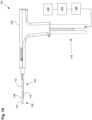
- Fig. 1Aillustrates a uterine ablation device 100 sized and configured to access the endometrium of a uterus and to deliver a heated vapor to the uterus to ablate uterine tissue.
- the devicecan be configured to ablate and treat the endometrial lining of the uterus as an alternative to hysterectomy for treating menorrhagia or other uterine diseases.
- the device 100can be configured to gain access to the uterus by being inserted through a cannula or hysteroscope.
- the device 100can include shaft 102, handle 104, distal tip 106, vapor ports 107, distal anchor or distal balloon 108, central or sealing balloon 110, proximal or positioning balloon 112, and connection lumens 118, which can couple the uterine ablation device to a control system (not shown) comprising a computer, a vapor generation system, and mechanisms configured to inflate and deflate the balloons as well as control the delivery and removal of integrity gas/fluid and vapor from the device. Additionally, connection lumens 118 can connect device 100 to a gas/fluid source 122, pressure regulator 124, and flow meter(s) 126.
- Vapor ports 107 near the distal tip 106 of the devicecan be fluidly coupled to the connection lumens 118 via inflow and outflow lumens (not shown).
- the vapor ports, inflow and outflow lumens, connection lumens, gas/fluid source, pressure regulator, and flow meterscan be configured for testing the integrity of the patient's uterus, proper placement of the device, and verifying the presence of flow between the inflow and outflow lumens of the device.
- the flow metercan be any flow meter as known in the art, including a thermal mass flow meter, an ultrasonic flow meter, a paddlewheel, or a variable area flow meter.
- an ultrasonic flow meterthat utilizes transit time and Doppler flow readings is advantageous since it is a non-contact system that does not need to physically interact with the fluid or gas media being employed in the integrity test.
- An ultrasonic flow metercan be easily adaptable to the exterior dimensions of an inflow lumen.
- a drip chamber within the inflow lumencan be used to manually visualize or record drips or flow from the fluid source as the integrity test indicates a sealed uterine cavity.
- a one way valvecan be placed in the inflow lumen on either side of the flow meter relative to the gas/fluid source.
- the one way valvecan allow for the flow of gas/fluid (e.g., saline) from the gas/fluid source to the device and uterine cavity.
- gas/fluide.g., saline
- the one way valveshould not interfere with the operation of the flow meter and its readings.
- the uterine cavityis a muscle that can undergo significant contractions during the integrity and patency tests. These contractions can push the fluid retrograde back through the saline lumen and past the flow meter. In doing so, flow meter measurements can become difficult to interpret or may produce sinusoidal waves in the output readings.
- the placement of the one way valve in the inflow lumencan eliminate retrograde fluid flow and stabilize readings for the flow meter during episodes of uterine contractions.
- Handle 104can be an ergonomic handle and can include features and controls for using the device (e.g., buttons, levers, indicia for providing feedback for depths of insertion, valves, etc.), including features for controlling inflation of balloons 108, 110, and 112, and for controlling the delivery and removal of integrity test gas/fluid and heated vapor from the device.
- the handlecan also include features and controls for testing the integrity of the patient's uterus, proper placement of the device and verifying the presence of flow between the inflow and outflow lumens of the device.
- the balloons described hereincan be any type of flexible balloon, such as rubber, latex, urethane, silicone, PET, LDPE, parylene, nylon, PE, combinations of these polymers, or can be manufactured from any other suitable material as known in the art.
- the distal anchorcomprises a balloon, but in other embodiments, the distal anchor comprises an expandable anchor or expansion mechanism, such as expandable frames, filters, nets, or cages, or non-expandable components that increase the diameter of the shaft of the uterine ablation device.
- the distal anchormay be referred to as a distal anchor or as a distal balloon.
- Shaft 102can be configured to deliver a heated vapor from a remote boiler (not shown) through the device and out of vapor ports 107 in distal tip 106.
- the shaftcan also be configured to return vapor that has exited the device, including bodily fluids, uterine materials, and condensate back through the vapor ports and into the shaft.
- vapor ports 107are illustrated as including both the vapor delivery and vapor return ports. However, in other embodiments, the vapor delivery ports can be separate and distinct from the vapor return ports.
- vapor delivery portsare intended to provide an even distribution of heated vapor through a cavity, and may comprise small lumens or holes on the end of the shaft.
- the vapor return portsare intended to return used vapor and condensate, and may comprise larger slots to prevent blood, tissue, etc. from blocking or clogging the return lumen.
- the devicecomprises inflow and outflow gas and/or fluid delivery channels to conduct uterine integrity and patency tests.
- the lumens to deliver and return vaporare the same as the channels to deliver and return gas and/or fluid for the uterine integrity and patency tests.
- uterine ablation device 100is shown in a collapsed delivery configuration, with distal balloon 108, sealing balloon 110, and positioning balloon 112 deflated to reduce the cross sectional diameter of the device and can be 6 mm in diameter during insertion or smaller.
- the reduced profileallows for easier access to through the vagina, cervical canal, and cervix to gain access to the uterus, and provides reduced patient discomfort during insertion.
- the outer dimensions of the uterine ablation deviceare such that introduction of the device into the uterine cavity can be achieved without the need for mechanical or pharmacological dilation of the os prior to device introduction.
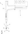
- Fig. 1Billustrates the uterine ablation device 100 of Figs. 1A with all three balloons inflated, including distal balloon 108, central sealing balloon 110, and positioning balloon 112.
- the central ballooncan be inflated with a fluid, such as saline, or alternatively, can be inflated with air.
- a fluidsuch as saline
- the positioning ballooncan be inflated with a room temperature medium, a cooled medium, or alternatively, a heated medium.
- the central sealing ballooncomprises a length along shaft 102 of approximately 15mm to 25mm.
- the central ballooncan be disposed on the shaft between the distal balloon or anchor and the proximal balloon. In some embodiments, the central balloon is adjacent to both the distal balloon and the proximal balloon. In other embodiments, there is a small gap or space between one or more of the balloons.
- the length and position of the central balloon on the shaftensures that when inflated, the central balloon seals the cervix off from the uterus near the internal os, but the balloon does not extend into the uterus or into the vagina of the patient.
- the central and proximal balloonscan comprise any diameter, but preferably should have a diameter large enough to be able to engage the walls of the cervix and/or the vagina in the average female patient. For instance, the central balloon may have an inflated outer diameter of 10mm and accommodate 9.5 psi of pressure in actual use.
- the proximal ballooncan have a larger diameter, such as 17mm and a lower inflation pressure of 7 psi.
- the distal tip of the ablation devicecan be inserted past an external os into the cervical canal of the patient, and past an internal os of the patient to gain access to the uterus.
- the distal ballooncan be positioned within the uterus distal to the internal os
- the sealing ballooncan be positioned at or proximal to the internal os and extending into the cervical canal
- the positioning ballooncan be positioned within the cervical canal and extending proximally into or towards the vagina.
- the distal ballooncan be inflated to the desired pressure.
- the ballooncan be inflated to a pressure of up to approximately 20 to 30 psi so as to prevent accidental withdrawal of the ablation device from the uterus. It should be noted that at this point, the distal balloon is positioned slightly past the internal os of the cervix. Inflation of the distal balloon can later serve as an anchor to prevent the device from sliding proximally out of the uterus.
- the proximal ballooncan be inflated to cause the device to assume a positioned configuration, with the distal balloon fully seated against the internal os and the positioning or proximal balloon expanded within the cervix and extending past the external os into the vagina.
- the proximal balloonis inflated, the balloon can expand outwardly from the cervix into the relatively unconstrained space of the vagina, which creates a compression force that pulls the device and the distal balloon proximally to engage against the interior portion of the internal os (also known as the cervical ostium or cervical os).
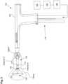
- Fig. 2illustrates ablation device 100 inserted into the uterus of a patient with balloons 108, 110, and 112 inflated as described above.
- an integrity testcan asses that the uterus is sealed, and determine leaks originating from 1) perforations to the uterine wall, or 2) leaks from inadequate sealing at the cervix or 3) leaks from the fallopian tubes.
- a second test that made an assessment for patencycould provide an indication to the physician whether the device was clogged with debris or placed within a false passage.
- This additional information to the physician, in conjunction with the integrity test,can provide greater assurance to the physician of device location during "blind" endometrial ablation procedures.
- a uterine integrity and patency testcould be useful for additional uterine procedures besides uterine ablation procedures such as the implantation of a device, implant, or a diagnostic or therapeutic agent.
- a separate unit or module that can conduct a uterine integrity and patency test, sequentially, separately, or individually, with a separate uterine cavity introducercan be employed without a uterine ablation device or system.
- a uterine integrity testcan contain the following elements and steps.
- gas/fluid source 122can be connected to pressure regulator 124 comprising either one regulator or an additional back pressure regulator.
- the gas/fluid sourcecan contain a gas, such as CO 2 , or inert gases, or a fluid, such as saline, Ringer's Lactate, non-isotonic solutions, glycerine, and mineral oil for example.
- the regulator 124can be configured to keep the pressure of the external gas source below a safety threshold value.
- the safety threshold valuecan be approximately 70mm Hg. The actual pressure amount or graduation may not be monitored and may not need to be.
- the fluid or gas from gas/fluid source 122can be driven at a constant pressure bounded by the safety threshold value (e.g., can be bounded by the maximum pressure the uterus will see during treatment, such as 70mm Hg).
- the safety threshold valuee.g., can be bounded by the maximum pressure the uterus will see during treatment, such as 70mm Hg.
- gas/fluid pressurecan be achieved by elevating the gas/fluid source 122 a height distance above the uterine cavity to create pressure. This height elevation can be verified by a measuring stick, tape or laser.
- An example of a clinically used height for a saline bagwould be at least 30 inches above the patient's uterus. At this height, the pressure would be between 50 and 70 mmHg. This pressure is low enough to be below the reported opening pressure of the fallopian tubes.
- a pressure sensor within the uterine cavitycan verify that the appropriate amount of pressure is being applied for the integrity test and patency tests.
- a self-adjusting feedback mechanismcan be employed to raise or lower the pressure of the saline source in response to pressure measurements taken from within the uterine cavity. As an example, this feedback mechanism can raise or lower the height of the saline source in response to the pressure measurements taken from within the uterine cavity.
- the systemcan measure a flow rate of gas/fluid exiting the distal lumen of the uterine device or uterine ablation device during the uterine integrity test.
- This flow ratecan also be used to determine the proper pressure or height of the gas/fluid source. For instance, flow rate readings can be taken while the gas/fluid source is at a certain height and the uterine device maintained within a known condition or in free space. As the height of the gas/fluid source is raised or lowered, the flow rate of the gas/fluid will respond accordingly until the gas/fluid source is placed at a height at the desired flow rate, or is pressurized to the desired amount. Likewise, the gas/fluid source can be raised or lowered by a self-adjusting feedback mechanism in response to the measured flow rate.
- the uterine ablation devicecan further include a flow meter 126 having a read out mechanism (not shown) to the end user.
- the flow metercan comprise an ultrasound sensor, or an optical sensor configured to sense the drip rate of the gas/fluid.
- the flow metercan be disposed near distal tip 106 of the device.
- the flow metercan be disposed within an outflow lumen of the device.
- the flow metercan be disposed external to the device but along the flow path between gas/fluid source 122 and the ablation device.
- the flow metercan be configured to measure and report a flow rate of fluid/gas or vapor as it moves through or exits the uterine ablation device.
- the read out mechanismcan be numerical, graphical, or icon based. Other variations include various audio and visual signals, indicia, qualitative indicia, alarms, and color identifiers.
- a filtermay or may not be attached to the flow meter.
- gassuch as CO 2
- a fluidsuch as saline
- gas/fluid source 122can be delivered from the gas/fluid source 122, through a pressure regulator, and through a flow meter 126 into the uterine ablation device 100.
- the gas/fluidcan be delivered into the uterus via both inflow lumen 129 and outflow lumen 131.
- a salinesuch as 0.9% NaCl can be delivered into the uterus during a uterine integrity test, to determine whether there are leaks in the uterus or cervical canal through which vapor could escape during an ablation procedure.
- the uterine ablation device 100can be coupled to an energy generator 124 and controller 123 for uterine ablation therapy.
- the vapor generatorcan be, for example, a vapor generator (as shown), but can also be any other type of energy generator, such as an RF energy generator, a cryotherapy generator, etc. Any type of energy modality can be used to ablate or treat the uterus after performing the integrity and patency tests described herein.
- a one way valve 127 as seen in Fig. 3can be located between the flow meter 126 and the uterine ablation device 100.
- the one way valve 127can be located in the handle of the uterine ablation device 100 as well as other components such as the flow meter 126 and valves 128a, 128b, and 128c.
- the one way valvecan reduce or eliminate retrograde flow of saline during uterine contractions.
- the one way valveis characterized as providing low resistance to flow in one direction (towards the uterine cavity) and high resistance to flow in the retrograde direction (towards the gas/fluid source).
- the one way valvecan stabilize flow values because retrograde flow values are eliminated.
- a controller of the uterine ablation devicecan be configured to open and close valves 128a, 128b, and 128c to allow gas or fluid to flow from source 122 into the inflow and outflow lumens 129 and 131 of the ablation device 100.
- Valves 128a, 128b, and 128ccan be any type of valve known in the art, such as solenoid valves, inflatable balloons, air cylinders, or electric/hydraulic actuators or cams and gears.
- the controllercan be configured to open valves 128a and 128b and close valve 128c, to prevent passage of gas/fluid into the waste container 133.
- valve 127 and valves 127a and 128bThis allows gas or fluid to flow from source 122, through flow meter 126, through one way valve 127 and valves 127a and 128b, and into inflow lumen 129 and outflow lumen 131.
- the flow metercan measure an integrity flow rate of the gas or fluid.
- the controller of the uterine ablation device or the vapor generatorcan run an integrity test algorithm to determine if the uterus is sealed.
- the algorithmcan analyze integrity flow rate data from the flow meter during the integrity test as gas/fluid is delivered into the uterus.
- the algorithmcan analyze a maximum flow rate and a minimum flow rate during an integrity test time window.
- the integrity test time windowcan be, for example, a rolling time window of a pre-selected duration.
- the algorithmanalyzes a maximum flow rate and a minimum flow rate continuously during a rolling 15-second integrity test time window. For each rolling integrity test time window, the minimum and maximum flow rates can be calculated.
- the difference between the minimum and maximum flow rates in each integrity test time windowcan be calculated to yield a delta flow value (maximum flow rate minus minimum flow rate), which can be used as an indicator of the stability of flow. For example, the larger the delta flow value, the less stable the flow of gas/fluid, and the smaller the delta flow value, the more stable the flow of gas/fluid. If the maximum flow rate and the delta flow value of gas or fluid stabilizes below an integrity threshold value, the controller can determine that the uterus is sealed.
- the testis comprised of two algorithms that compare flow to an integrity threshold value concurrently with a second algorithm that compares the delta flow value to the integrity threshold value, and uses both of these comparisons to determine the ultimate outcome of the integrity test. The application of both of these comparisons provides greater sensitivity in the test results.
- this integrity flow rate delta threshold valuecan be approximately 5 ml/min. Therefore, in some embodiments, a uterus is considered to "pass" the uterine integrity test if both the maximum flow rate and the integrity flow rate delta threshold value are below 5ml/min over a rolling integrity test time window.
- the testcan include different thresholds for maximum flow rate and the delta flow value.
- the uterine integrity testcan run for a pre-set time period. For example, the test can run for 60 seconds, and subsequent rolling 15-second windows can be analyzed to determine if the uterus is sealed during the 60 second time period.
- the delta flow valuecan be defined as a standard deviation of the average flow that is compared to a threshold value. This delta flow value can then be compared to the threshold value to determine if the uterus is sealed.
- the return channelcomprises a balloon valve 128c which can be activated upon the start of the integrity test to close off the egress of the gas/fluid through the return channel of the uterine ablation device.
- a change of flowcan be detected by the flow meter 126 on the input line.
- the specifics of the changes in flowe.g., how the flow reacts to closing of the return line with the valve
- an integration under the graphical curve of flow rate versus timeprovides a volume assessment of the size of uterine cavity.
- the amount of volumecan provide the physician information not only on the size of the uterus, but whether the device is improperly embedded in a false passage (smaller volume amount) or in the peritoneal cavity (larger volume amount).
- the amount of flow in the inflow and outflow channelscan be measured in a patency test and used to determine the presence of an obstruction that may affect the flow of vapor during the ablation procedure. Based on this determination or patency test, the device may be repositioned or replaced prior to delivery of vapor. For example, in one embodiment, referring to Fig.
- a method of performing a patency testcan comprise delivering gas or fluid from inflow lumen 129 of the uterine device into the uterus, also referred to as the fluid infusion tip, removing gas or fluid from the uterus with outflow lumen 131 of the uterine device, also referred to as the fluid outflow tip, and determining that the uterine device is not clogged or embedded in tissue if a flow rate of gas or fluid is observed in the flow meter of the inflow lumen of the uterine device.
- valves 128a and 128bcontrol the flow of gas/fluid to the uterine ablation device 100 and valve 128c control the flow of gas/fluid from the outflow lumen 131 into the outflow canister or waste container 133.
- Control of the valves 128a and 128b and 128ccan be performed by a separate controller and software unit shown as 123.
- the controlleralso performs a patency test.
- the controllercan be configured to open valves 128b and 128c, but close valve 128a. This allows gas or fluid to flow from source 122, through flow meter 126, through one way valve 127 and valve 128b, and into inflow lumen 129. Gas or fluid can be removed through outflow lumen 131, through valve 128c, and into a waste container 133. As the gas or fluid enters and is removed from the uterus, the flow meter can measure a patency flow rate of the gas or fluid.
- the controllerdetermines that the device is not clogged or embedded into tissue.
- observing or measuring a flow of fluid or gas in outflow lumen 131is used to determine that the device is not clogged or embedded in tissue.
- a flow rate above a patency test threshold during a rolling patency test time windowcan indicate that the lumens are not clogged or that the distal end of the uterine ablation device is not embedded into tissue.
- the patency test thresholdcan be greater than 5 ml/min
- the rolling patency test time windowcan be a 5 second time period.
- the flow metercan measure the patency flow rate in rolling patency time windows (e.g., rolling 5 second periods) and the controller can analyze the measured rate. If the patency flow rate is maintained above the patency test threshold (e.g., 5 ml/min) during a rolling patency time window, then the patency test is considered passed and the test can be stopped. Passing the patency test indicates that the uterine ablation device is not obstructed or placed in false passage.
- the physicianshould repeat the insertion steps and/or repeat the integrity test and patency test prior to initiating uterine ablation.
- the patency flow rateis below the threshold of 5 ml/min during the rolling patency test time window, the uterine ablation device may need to be repositioned.
- the uterine cavitycan be substantially filled with the gas/fluid provided during the integrity test.
- the closed outflow valve during the integrity testprevents gas or fluid from exiting the uterine cavity into the waste container 133.
- the valve 128cis opened only partially, preferably in the range of 20-50% open for a flow rate greater than 5 ml/min and less than 40 ml/min, so the uterine cavity distension achieved during the integrity test is temporarily maintained when the patency test checks for open flow through the uterine ablation device. Certain types of valves are better suited for partial opening.
- the balloon valveis pulsed at various duty cycles to partially open the valve.
- partial opening of the valveprevents the uterine cavity from collapsing too quickly around the tip of the uterine ablation device which, in some instances, may cause a false positive failure of the patency test.
- partial opening of the valvecan be achieved by pulsing the opening of the valve at a specified duty cycle until flow through the vapor probe begins, or alternatively until the uterine pressure begins to drop.
- the valve 128ccan be opened rapidly just until flow through the valve begins. This rapid drop opening of the valve can be achieved by pulsing the valve initially with a high duty cycle, then shortening the pulsing (or lowering the duty cycle) as the valve approaches the range where flow through the valve begins. Once the patency flow rate increases above a threshold (or by a specific rate of increase), the valve can be maintained.
- the valve 128ccan be a balloon filled to as much as 20 psig to occlude the tubing leading to waste container 133.
- the balloon valvecan be pulsed open for up to 40 msec every 200 msec until the balloon pressure falls to as low as 5 psig.
- the valve opening timecan then be reduced even further until the balloon pressure falls to between 3-4 psig.
- the valvecan continue to be pulsed until flow increases to a level of 0.20 ml/min or until flow rises above the threshold value (e.g., above 5 ml/min).
- Fig. 5shows one specific embodiment where the outflow valve (e.g., valve 128c from Fig. 3 ) comprises an inflatable balloon. Inflating the balloon causes obstruction of the outflow lumen of the uterine ablation device, and deflating the balloon allows flow out of the device and into the waste container.
- Fig. 5shows the outflow valve pressure 136 (mmHg), the flow 138 (ml/min) through the uterine ablation device, and the uterine cavity pressure 140 (mmHg) during a typical patency test.
- the cavity pressureshould be above 52mmHg, the outflow valve pressure about 20psi, and the flow through the uterine ablation device close to zero.
- the outflow valve pressuredecreases rapidly, then the rate of deflation decreases to zero as flow through the device begins, shown by arrow 142.
- the cavity pressuredrops gradually as flow increases.
- the patency algorithmcan run concurrently with deflation of the outflow valve.
- the deflation period of the outflow valveis typically from 3 to 40 msec.
Landscapes
- Health & Medical Sciences (AREA)
- Life Sciences & Earth Sciences (AREA)
- Engineering & Computer Science (AREA)
- Animal Behavior & Ethology (AREA)
- Public Health (AREA)
- Veterinary Medicine (AREA)
- General Health & Medical Sciences (AREA)
- Heart & Thoracic Surgery (AREA)
- Biomedical Technology (AREA)
- Surgery (AREA)
- Medical Informatics (AREA)
- Molecular Biology (AREA)
- Biophysics (AREA)
- Physics & Mathematics (AREA)
- Pathology (AREA)
- Hematology (AREA)
- Reproductive Health (AREA)
- Gynecology & Obstetrics (AREA)
- Anesthesiology (AREA)
- Nuclear Medicine, Radiotherapy & Molecular Imaging (AREA)
- Pregnancy & Childbirth (AREA)
- Pulmonology (AREA)
- Plasma & Fusion (AREA)
- Otolaryngology (AREA)
- Surgical Instruments (AREA)
Description
- The present disclosure generally relates to uterine procedures incorporating a distension media such as a fluid or a gas that could be used with endoscopic procedures or other visualization systems such as ultrasound or fluoroscopy. The present disclosure is particular suited for endometrial ablation of the uterine lining. More specifically, the present disclosure relates to endometrial ablation with a heated vapor.
- Endometrial ablation (i.e., the removal or destruction of the endometrial lining of the uterus) is used as an alternative to hysterectomy for treating menorrhagia, or other uterine diseases. One prior technique for performing endometrial ablation employs a resectoscope (i.e., a hysteroscope with a built-in wire loop or other ablative devices) that is inserted transcervically into the uterus, and uses radio-frequency electrical current (RF current) to remove or coagulate the endometrial tissue. These standard techniques typically are performed in a hospital setting and importantly utilize hysteroscopy for visualization of the procedure while treating the uterine lining.
- Some approaches make use of heated fluid to ablate the endometrium. For example, early journal articles describe the use of steam to treat uterine hemorrhage. The use of steam for this purpose was later discredited, apparently due to patient morbidity and mortality. See, e.g., Fuller
U.S. Patent No. 6,139,571 . More recent descriptions of the use of injecting hot fluid into the uterus have been described. Uterine therapies employing a contained fluid have also been described. - In an effort to simplify the procedure, approaches have been developed that do not require concurrent hysteroscopic visualization. In practice, many of these techniques recommend that the physician or user employ hysteroscopy to visualize and inspect the uterine cavity prior to performing the endometrial ablation procedure. In addition, hysteroscopy may be employed at the conclusion of the endometrial ablation procedure as a method to inspect the uterine cavity post treatment. During this hysteroscopic inspection, the physician is verifying that the uterine cavity is not perforated although perforations may not be readily apparent even with hysteroscopic visualization. In general, a physician seeks to avoid perforations for many reasons including the potential for unintended injuries to neighboring organs and maintaining or confining the treatment area to specifically the uterine cavity in the case of endometrial ablation procedures.
- Endometrial ablation techniques that do not require active hysteroscopic visualization during treatment operation are commonly referred to as "blind" techniques since the physician is using tactile feel, or markers and indicia on the endometrial ablation device to indicate proper placement of the device in the uterine cavity. One of these particular devices utilizes a balloon-based system using heated saline as the thermal energy source for the ablation of tissue. High frequency, or radiofrequency (RF), energy has also been used to perform thermal ablation of endometrial tissue. Current products for performing endometrial ablation include the NOVASURE® procedure and a system marketed under the trade name THERMACHOICE®, by Ethicon, Inc. of Somerville, N.J. Cryogenic ablation, or "cryoablation," such as HER OPTION® from American Medical Systems, Inc., is another endometrial treatment approach. All of the products above are characterized as "blind" or not requiring direct hysteroscopic visualization during the treatment.
- In utilizing an endometrial ablation technology that does not require hysteroscopic visualization, it would be beneficial to employ a test to verify that the uterine cavity is intact or unperforated prior to performing the treatment. Such tests are referred to as uterine integrity tests and these tests can be performed with endometrial ablation procedures and any procedure of the uterus or hollow body cavity or organ. In addition, these tests can be used with hysteroscopic procedures since a perforation may not be readily detected even under direct vision.
- Integrity tests employ saline or gas, preferably carbon dioxide gas, as agents to verify if the uterine cavity is intact in regards to holding fluid or gas pressure. The gas or fluid is supplied under pressure to the uterine cavity and a leak in the uterine cavity, whether it is a perforation, an unsealed cervical canal, or the effect of excess fluid exiting the fallopian tubes, can be discerned.
Stem et al. (US 5,562,720 ) andSampson et al. (US 6,554,780 ,US 6,743,184 ,US 6,872,183 , andUS 7,063,670 ) describe such pressure techniques while other approaches check for fluid imbalances between an input source and output collection using volume measurements. Other approaches mention using flow rate and pressure measurements.WO 2013/052967 A1 discloses a uterine treatment device, comprising: - a shaft sized and configured for insertion into a uterus of a patient;
- inflow and outflow lumens disposed along a length of the shaft;
- at least one inflow port disposed at a distal end of the inflow lumen;
- at least one outflow port disposed at a distal end of the outflow lumen;
- a gas/fluid source operatively coupled to the inflow and outflow lumens;
- at least one flow meter disposed between the gas/fluid source and the shaft; and a controller configured deliver gas or fluid from the gas/fluid source through the inflow lumen into the uterus, detect with the at least one flow meter an integrity flow rate of gas or fluid as it is delivered into the uterus, and determine that the uterus is sealed if the integrity flow rate decreases below an integrity flow rate threshold value;
- the controller also configured to, if it is determined that the uterus is sealed, deliver gas or fluid through the inflow lumen into the uterus, remove gas or fluid from the uterus with the outflow lumen, detect with the at least one flow meter a patency flow rate of gas or fluid, and determine that the uterine treatment device is not clogged or embedded in tissue based on the patency flow rate.
- The invention is defined in claim 1. Further aspects and preferred embodiments are defined in the dependent claims.
Figs. 1A-1B illustrate an example of a uterine ablation device.Fig. 2 shows an example of a uterine ablation device inserted into a uterus.Fig. 3 illustrates an integrity test of the uterine ablation device.Fig. 4 illustrates a patency test of the uterine ablation device.Fig. 5 charts the relationship between outflow valve pressure, uterine cavity pressure, and flow through a uterine ablation device.Fig. 1A illustrates auterine ablation device 100 sized and configured to access the endometrium of a uterus and to deliver a heated vapor to the uterus to ablate uterine tissue. The device can be configured to ablate and treat the endometrial lining of the uterus as an alternative to hysterectomy for treating menorrhagia or other uterine diseases. In some embodiments, thedevice 100 can be configured to gain access to the uterus by being inserted through a cannula or hysteroscope. Thedevice 100 can includeshaft 102,handle 104,distal tip 106,vapor ports 107, distal anchor ordistal balloon 108, central orsealing balloon 110, proximal orpositioning balloon 112, andconnection lumens 118, which can couple the uterine ablation device to a control system (not shown) comprising a computer, a vapor generation system, and mechanisms configured to inflate and deflate the balloons as well as control the delivery and removal of integrity gas/fluid and vapor from the device. Additionally,connection lumens 118 can connectdevice 100 to a gas/fluid source 122,pressure regulator 124, and flow meter(s) 126.Vapor ports 107 near thedistal tip 106 of the device can be fluidly coupled to theconnection lumens 118 via inflow and outflow lumens (not shown). The vapor ports, inflow and outflow lumens, connection lumens, gas/fluid source, pressure regulator, and flow meters can be configured for testing the integrity of the patient's uterus, proper placement of the device, and verifying the presence of flow between the inflow and outflow lumens of the device.- The flow meter can be any flow meter as known in the art, including a thermal mass flow meter, an ultrasonic flow meter, a paddlewheel, or a variable area flow meter. In one embodiment, an ultrasonic flow meter that utilizes transit time and Doppler flow readings is advantageous since it is a non-contact system that does not need to physically interact with the fluid or gas media being employed in the integrity test. An ultrasonic flow meter can be easily adaptable to the exterior dimensions of an inflow lumen. In addition, a drip chamber within the inflow lumen can be used to manually visualize or record drips or flow from the fluid source as the integrity test indicates a sealed uterine cavity. In some uterine procedures, it may be advantageous to use other types of fluid besides saline including Lactated Ringers, non-isotonic solutions for certain electrosurgical procedures, gels, foams, fluids of varying viscosity for some ultrasonographic procedures, or other fluids used in uterine procedures.
- In one embodiment, a one way valve can be placed in the inflow lumen on either side of the flow meter relative to the gas/fluid source. The one way valve can allow for the flow of gas/fluid (e.g., saline) from the gas/fluid source to the device and uterine cavity. The one way valve should not interfere with the operation of the flow meter and its readings. In operation, the uterine cavity is a muscle that can undergo significant contractions during the integrity and patency tests. These contractions can push the fluid retrograde back through the saline lumen and past the flow meter. In doing so, flow meter measurements can become difficult to interpret or may produce sinusoidal waves in the output readings. The placement of the one way valve in the inflow lumen can eliminate retrograde fluid flow and stabilize readings for the flow meter during episodes of uterine contractions.
- Handle 104 can be an ergonomic handle and can include features and controls for using the device (e.g., buttons, levers, indicia for providing feedback for depths of insertion, valves, etc.), including features for controlling inflation of
balloons - The balloons described herein can be any type of flexible balloon, such as rubber, latex, urethane, silicone, PET, LDPE, parylene, nylon, PE, combinations of these polymers, or can be manufactured from any other suitable material as known in the art. It should be noted that in some embodiments, the distal anchor comprises a balloon, but in other embodiments, the distal anchor comprises an expandable anchor or expansion mechanism, such as expandable frames, filters, nets, or cages, or non-expandable components that increase the diameter of the shaft of the uterine ablation device. For purposes of this disclosure, however, the distal anchor may be referred to as a distal anchor or as a distal balloon.
Shaft 102 can be configured to deliver a heated vapor from a remote boiler (not shown) through the device and out ofvapor ports 107 indistal tip 106. The shaft can also be configured to return vapor that has exited the device, including bodily fluids, uterine materials, and condensate back through the vapor ports and into the shaft. InFig. 1A ,vapor ports 107 are illustrated as including both the vapor delivery and vapor return ports. However, in other embodiments, the vapor delivery ports can be separate and distinct from the vapor return ports. For example, vapor delivery ports are intended to provide an even distribution of heated vapor through a cavity, and may comprise small lumens or holes on the end of the shaft. The vapor return ports, in contrast, are intended to return used vapor and condensate, and may comprise larger slots to prevent blood, tissue, etc. from blocking or clogging the return lumen. The device comprises inflow and outflow gas and/or fluid delivery channels to conduct uterine integrity and patency tests. In some embodiments, the lumens to deliver and return vapor are the same as the channels to deliver and return gas and/or fluid for the uterine integrity and patency tests.- Referring still to
Fig. 1A ,uterine ablation device 100 is shown in a collapsed delivery configuration, withdistal balloon 108, sealingballoon 110, andpositioning balloon 112 deflated to reduce the cross sectional diameter of the device and can be 6 mm in diameter during insertion or smaller. When the device is in the delivery configuration, the reduced profile allows for easier access to through the vagina, cervical canal, and cervix to gain access to the uterus, and provides reduced patient discomfort during insertion. In some embodiments, the outer dimensions of the uterine ablation device are such that introduction of the device into the uterine cavity can be achieved without the need for mechanical or pharmacological dilation of the os prior to device introduction. Fig. 1B illustrates theuterine ablation device 100 ofFigs. 1A with all three balloons inflated, includingdistal balloon 108,central sealing balloon 110, andpositioning balloon 112. The central balloon can be inflated with a fluid, such as saline, or alternatively, can be inflated with air. Although three balloons are depicted inFig. 1B , in other variations one, two, four, or more balloons may be provided, and other balloon shapes may be used. The positioning balloon can be inflated with a room temperature medium, a cooled medium, or alternatively, a heated medium. In some embodiments, the central sealing balloon comprises a length alongshaft 102 of approximately 15mm to 25mm. The central balloon can be disposed on the shaft between the distal balloon or anchor and the proximal balloon. In some embodiments, the central balloon is adjacent to both the distal balloon and the proximal balloon. In other embodiments, there is a small gap or space between one or more of the balloons. The length and position of the central balloon on the shaft ensures that when inflated, the central balloon seals the cervix off from the uterus near the internal os, but the balloon does not extend into the uterus or into the vagina of the patient. The central and proximal balloons can comprise any diameter, but preferably should have a diameter large enough to be able to engage the walls of the cervix and/or the vagina in the average female patient. For instance, the central balloon may have an inflated outer diameter of 10mm and accommodate 9.5 psi of pressure in actual use. The proximal balloon can have a larger diameter, such as 17mm and a lower inflation pressure of 7 psi.- Placement of the ablation device of
Figs. 1A-1B will now be described. The distal tip of the ablation device can be inserted past an external os into the cervical canal of the patient, and past an internal os of the patient to gain access to the uterus. In one embodiment, the distal balloon can be positioned within the uterus distal to the internal os, the sealing balloon can be positioned at or proximal to the internal os and extending into the cervical canal, and the positioning balloon can be positioned within the cervical canal and extending proximally into or towards the vagina. - Once the distal tip of the ablation device is disposed within the uterus, just distal to the internal os, the distal balloon can be inflated to the desired pressure. In some embodiments, the balloon can be inflated to a pressure of up to approximately 20 to 30 psi so as to prevent accidental withdrawal of the ablation device from the uterus. It should be noted that at this point, the distal balloon is positioned slightly past the internal os of the cervix. Inflation of the distal balloon can later serve as an anchor to prevent the device from sliding proximally out of the uterus.
- After inflating the distal balloon, the proximal balloon can be inflated to cause the device to assume a positioned configuration, with the distal balloon fully seated against the internal os and the positioning or proximal balloon expanded within the cervix and extending past the external os into the vagina. As the proximal balloon is inflated, the balloon can expand outwardly from the cervix into the relatively unconstrained space of the vagina, which creates a compression force that pulls the device and the distal balloon proximally to engage against the interior portion of the internal os (also known as the cervical ostium or cervical os).
Fig. 2 illustratesablation device 100 inserted into the uterus of a patient withballoons - After positioning the ablation device but prior to delivery of vapor, it can be advantageous to assess the integrity of the uterus to test that the vapor delivery tip of the device is positioned within a sealed uterus and to test that there is flow between the inflow and outflow lumens, by performing an integrity test and a patency test. The amount of fluid and rate in which it flows into the uterine cavity can provide the physician an indication of the size of the uterine cavity and whether the device is in a false passage. An integrity test can asses that the uterus is sealed, and determine leaks originating from 1) perforations to the uterine wall, or 2) leaks from inadequate sealing at the cervix or 3) leaks from the fallopian tubes.
- A second test that made an assessment for patency, referred to as the device lumens patency test or patency test, could provide an indication to the physician whether the device was clogged with debris or placed within a false passage. This additional information to the physician, in conjunction with the integrity test, can provide greater assurance to the physician of device location during "blind" endometrial ablation procedures.
- In clinical use, a uterine integrity and patency test could be useful for additional uterine procedures besides uterine ablation procedures such as the implantation of a device, implant, or a diagnostic or therapeutic agent. In these cases, a separate unit or module that can conduct a uterine integrity and patency test, sequentially, separately, or individually, with a separate uterine cavity introducer can be employed without a uterine ablation device or system.
- In one embodiment, a uterine integrity test can contain the following elements and steps. Referring to
Figs. 1A-1B andFig. 2 , gas/fluid source 122 can be connected topressure regulator 124 comprising either one regulator or an additional back pressure regulator. The gas/fluid source can contain a gas, such as CO2, or inert gases, or a fluid, such as saline, Ringer's Lactate, non-isotonic solutions, glycerine, and mineral oil for example. Theregulator 124 can be configured to keep the pressure of the external gas source below a safety threshold value. In one embodiment, the safety threshold value can be approximately 70mm Hg. The actual pressure amount or graduation may not be monitored and may not need to be. The fluid or gas from gas/fluid source 122 can be driven at a constant pressure bounded by the safety threshold value (e.g., can be bounded by the maximum pressure the uterus will see during treatment, such as 70mm Hg). In addition, it can be useful to operate a uterine integrity test at a pressure equal to higher than the pressure required for conducting the endometrial ablation or other uterine procedure. - In one embodiment, gas/fluid pressure can be achieved by elevating the gas/fluid source 122 a height distance above the uterine cavity to create pressure. This height elevation can be verified by a measuring stick, tape or laser. An example of a clinically used height for a saline bag would be at least 30 inches above the patient's uterus. At this height, the pressure would be between 50 and 70 mmHg. This pressure is low enough to be below the reported opening pressure of the fallopian tubes. In addition, a pressure sensor within the uterine cavity can verify that the appropriate amount of pressure is being applied for the integrity test and patency tests. A self-adjusting feedback mechanism can be employed to raise or lower the pressure of the saline source in response to pressure measurements taken from within the uterine cavity. As an example, this feedback mechanism can raise or lower the height of the saline source in response to the pressure measurements taken from within the uterine cavity.
- In some embodiments, the system can measure a flow rate of gas/fluid exiting the distal lumen of the uterine device or uterine ablation device during the uterine integrity test. This flow rate can also be used to determine the proper pressure or height of the gas/fluid source. For instance, flow rate readings can be taken while the gas/fluid source is at a certain height and the uterine device maintained within a known condition or in free space. As the height of the gas/fluid source is raised or lowered, the flow rate of the gas/fluid will respond accordingly until the gas/fluid source is placed at a height at the desired flow rate, or is pressurized to the desired amount. Likewise, the gas/fluid source can be raised or lowered by a self-adjusting feedback mechanism in response to the measured flow rate.
- In some embodiments, the uterine ablation device can further include a
flow meter 126 having a read out mechanism (not shown) to the end user. In one embodiment, the flow meter can comprise an ultrasound sensor, or an optical sensor configured to sense the drip rate of the gas/fluid. In some embodiments, the flow meter can be disposed neardistal tip 106 of the device. In other embodiments, the flow meter can be disposed within an outflow lumen of the device. In yet another embodiment, the flow meter can be disposed external to the device but along the flow path between gas/fluid source 122 and the ablation device. The flow meter can be configured to measure and report a flow rate of fluid/gas or vapor as it moves through or exits the uterine ablation device. The read out mechanism can be numerical, graphical, or icon based. Other variations include various audio and visual signals, indicia, qualitative indicia, alarms, and color identifiers. A filter may or may not be attached to the flow meter. - Referring to
Figs. 2 and3 , to perform a uterine integrity test, gas, such as CO2, or a fluid, such as saline, can be delivered from the gas/fluid source 122, through a pressure regulator, and through aflow meter 126 into theuterine ablation device 100. As shown inFig. 3 , the gas/fluid can be delivered into the uterus via bothinflow lumen 129 andoutflow lumen 131. In one specific embodiment, a saline such as 0.9% NaCl can be delivered into the uterus during a uterine integrity test, to determine whether there are leaks in the uterus or cervical canal through which vapor could escape during an ablation procedure. Theuterine ablation device 100 can be coupled to anenergy generator 124 andcontroller 123 for uterine ablation therapy. The vapor generator can be, for example, a vapor generator (as shown), but can also be any other type of energy generator, such as an RF energy generator, a cryotherapy generator, etc. Any type of energy modality can be used to ablate or treat the uterus after performing the integrity and patency tests described herein. - In one embodiment, a one
way valve 127 as seen inFig. 3 can be located between theflow meter 126 and theuterine ablation device 100. In other variations the oneway valve 127 can be located in the handle of theuterine ablation device 100 as well as other components such as theflow meter 126 andvalves - A controller of the uterine ablation device, either integrated into the device or into the vapor generator coupled to the device, can be configured to open and
close valves source 122 into the inflow andoutflow lumens ablation device 100.Valves valves close valve 128c, to prevent passage of gas/fluid into thewaste container 133. This allows gas or fluid to flow fromsource 122, throughflow meter 126, through oneway valve 127 andvalves 127a and 128b, and intoinflow lumen 129 andoutflow lumen 131. As the gas or fluid enters the uterus, the flow meter can measure an integrity flow rate of the gas or fluid. - In one embodiment, the controller of the uterine ablation device or the vapor generator can run an integrity test algorithm to determine if the uterus is sealed. The algorithm can analyze integrity flow rate data from the flow meter during the integrity test as gas/fluid is delivered into the uterus. Specifically, the algorithm can analyze a maximum flow rate and a minimum flow rate during an integrity test time window. The integrity test time window can be, for example, a rolling time window of a pre-selected duration. In one specific embodiment, the algorithm analyzes a maximum flow rate and a minimum flow rate continuously during a rolling 15-second integrity test time window. For each rolling integrity test time window, the minimum and maximum flow rates can be calculated. The difference between the minimum and maximum flow rates in each integrity test time window can be calculated to yield a delta flow value (maximum flow rate minus minimum flow rate), which can be used as an indicator of the stability of flow. For example, the larger the delta flow value, the less stable the flow of gas/fluid, and the smaller the delta flow value, the more stable the flow of gas/fluid. If the maximum flow rate and the delta flow value of gas or fluid stabilizes below an integrity threshold value, the controller can determine that the uterus is sealed. Importantly, the test is comprised of two algorithms that compare flow to an integrity threshold value concurrently with a second algorithm that compares the delta flow value to the integrity threshold value, and uses both of these comparisons to determine the ultimate outcome of the integrity test. The application of both of these comparisons provides greater sensitivity in the test results.
- In some embodiments, this integrity flow rate delta threshold value can be approximately 5 ml/min. Therefore, in some embodiments, a uterus is considered to "pass" the uterine integrity test if both the maximum flow rate and the integrity flow rate delta threshold value are below 5ml/min over a rolling integrity test time window. Alternatively, the test can include different thresholds for maximum flow rate and the delta flow value.
- In some embodiments, the uterine integrity test can run for a pre-set time period. For example, the test can run for 60 seconds, and subsequent rolling 15-second windows can be analyzed to determine if the uterus is sealed during the 60 second time period. In another embodiment, the delta flow value can be defined as a standard deviation of the average flow that is compared to a threshold value. This delta flow value can then be compared to the threshold value to determine if the uterus is sealed.
- According to the invention, the return channel comprises a
balloon valve 128c which can be activated upon the start of the integrity test to close off the egress of the gas/fluid through the return channel of the uterine ablation device. When the return flow of gas/fluid through the return channel is stopped with the valve, a change of flow can be detected by theflow meter 126 on the input line. In addition to determining if there is a leak or if the device is positioned properly, the specifics of the changes in flow (e.g., how the flow reacts to closing of the return line with the valve) can provide the following the indications in some cases: a) the size of the uterine cavity; and b) the presence of a leak or lack of integrity in the system. For instance in clinical use with uteri of varying sizes, an integration under the graphical curve of flow rate versus time provides a volume assessment of the size of uterine cavity. The amount of volume can provide the physician information not only on the size of the uterus, but whether the device is improperly embedded in a false passage (smaller volume amount) or in the peritoneal cavity (larger volume amount). - Immediately after performing the integrity test above, the amount of flow in the inflow and outflow channels can be measured in a patency test and used to determine the presence of an obstruction that may affect the flow of vapor during the ablation procedure. Based on this determination or patency test, the device may be repositioned or replaced prior to delivery of vapor. For example, in one embodiment, referring to
Fig. 4 , a method of performing a patency test can comprise delivering gas or fluid frominflow lumen 129 of the uterine device into the uterus, also referred to as the fluid infusion tip, removing gas or fluid from the uterus withoutflow lumen 131 of the uterine device, also referred to as the fluid outflow tip, and determining that the uterine device is not clogged or embedded in tissue if a flow rate of gas or fluid is observed in the flow meter of the inflow lumen of the uterine device. InFigs. 3-4 ,valves uterine ablation device 100 andvalve 128c control the flow of gas/fluid from theoutflow lumen 131 into the outflow canister orwaste container 133. Control of thevalves - If it has been determined that the uterus is sealed based on the integrity test performed and described in
Fig. 3 , the controller also performs a patency test. In one embodiment, referring toFig. 4 , the controller can be configured to openvalves close valve 128a. This allows gas or fluid to flow fromsource 122, throughflow meter 126, through oneway valve 127 andvalve 128b, and intoinflow lumen 129. Gas or fluid can be removed throughoutflow lumen 131, throughvalve 128c, and into awaste container 133. As the gas or fluid enters and is removed from the uterus, the flow meter can measure a patency flow rate of the gas or fluid. If the patency flow rate is maintained above a patency flow rate threshold value, the controller determines that the device is not clogged or embedded into tissue. According to the invention, observing or measuring a flow of fluid or gas inoutflow lumen 131 is used to determine that the device is not clogged or embedded in tissue. A flow rate above a patency test threshold during a rolling patency test time window can indicate that the lumens are not clogged or that the distal end of the uterine ablation device is not embedded into tissue. - In one specific embodiment, the patency test threshold can be greater than 5 ml/min, and the rolling patency test time window can be a 5 second time period. Thus, the flow meter can measure the patency flow rate in rolling patency time windows (e.g., rolling 5 second periods) and the controller can analyze the measured rate. If the patency flow rate is maintained above the patency test threshold (e.g., 5 ml/min) during a rolling patency time window, then the patency test is considered passed and the test can be stopped. Passing the patency test indicates that the uterine ablation device is not obstructed or placed in false passage. If the patency test threshold is not satisfied, the physician should repeat the insertion steps and/or repeat the integrity test and patency test prior to initiating uterine ablation. When the patency flow rate is below the threshold of 5 ml/min during the rolling patency test time window, the uterine ablation device may need to be repositioned.
- During the transition from the end of integrity test to the start of the patency test, the uterine cavity can be substantially filled with the gas/fluid provided during the integrity test. As described above, the closed outflow valve during the integrity test prevents gas or fluid from exiting the uterine cavity into the
waste container 133. According to the invention, thevalve 128c is opened only partially, preferably in the range of 20-50% open for a flow rate greater than 5 ml/min and less than 40 ml/min, so the uterine cavity distension achieved during the integrity test is temporarily maintained when the patency test checks for open flow through the uterine ablation device. Certain types of valves are better suited for partial opening. According to the invention, the balloon valve is pulsed at various duty cycles to partially open the valve. The higher the duty cycle, the more quickly the valve can be opened. Partial opening of the valve prevents the uterine cavity from collapsing too quickly around the tip of the uterine ablation device which, in some instances, may cause a false positive failure of the patency test. In one embodiment, partial opening of the valve can be achieved by pulsing the opening of the valve at a specified duty cycle until flow through the vapor probe begins, or alternatively until the uterine pressure begins to drop. In another embodiment, thevalve 128c can be opened rapidly just until flow through the valve begins. This rapid drop opening of the valve can be achieved by pulsing the valve initially with a high duty cycle, then shortening the pulsing (or lowering the duty cycle) as the valve approaches the range where flow through the valve begins. Once the patency flow rate increases above a threshold (or by a specific rate of increase), the valve can be maintained. - In one specific embodiment, the
valve 128c can be a balloon filled to as much as 20 psig to occlude the tubing leading towaste container 133. The balloon valve can be pulsed open for up to 40 msec every 200 msec until the balloon pressure falls to as low as 5 psig. The valve opening time can then be reduced even further until the balloon pressure falls to between 3-4 psig. The valve can continue to be pulsed until flow increases to a level of 0.20 ml/min or until flow rises above the threshold value (e.g., above 5 ml/min). Fig. 5 shows one specific embodiment where the outflow valve (e.g.,valve 128c fromFig. 3 ) comprises an inflatable balloon. Inflating the balloon causes obstruction of the outflow lumen of the uterine ablation device, and deflating the balloon allows flow out of the device and into the waste container.Fig. 5 shows the outflow valve pressure 136 (mmHg), the flow 138 (ml/min) through the uterine ablation device, and the uterine cavity pressure 140 (mmHg) during a typical patency test. At the completion of a typical integrity test, the cavity pressure should be above 52mmHg, the outflow valve pressure about 20psi, and the flow through the uterine ablation device close to zero. In the first few seconds of the patency test, the outflow valve pressure decreases rapidly, then the rate of deflation decreases to zero as flow through the device begins, shown byarrow 142. The cavity pressure drops gradually as flow increases. The patency algorithm can run concurrently with deflation of the outflow valve. In some embodiments, the deflation period of the outflow valve is typically from 3 to 40 msec.- As for additional details pertinent to the present invention, materials and manufacturing techniques may be employed as within the level of those with skill in the relevant art. The same may hold true with respect to method-based aspects of the disclosure in terms of additional acts commonly or logically employed. Likewise, reference to a singular item includes the possibility that there are plural of the same items present. More specifically, as used herein and in the appended claims, the singular forms "a," "and," "said," and "the" include plural referents unless the context clearly dictates otherwise. Unless defined otherwise herein, all technical and scientific terms used herein have the same meaning as commonly understood by one of ordinary skill in the art to which this invention belongs. The breadth of the present invention is not to be limited by the subject specification, but rather only by the plain meaning of the claim terms employed.
Claims (4)
- A uterine ablation device (100), comprising:a shaft (102) adapted to be inserted into a uterus of a patient, the shaft including an outflow lumen (131) and an inflow lumen (129);a gas/fluid source (122) configured to deliver gas or fluid through the inflow lumen of the shaft into the uterus;an outflow valve (128c) configured to seal the outflow lumen of the shaft, the outflow valve being a balloon valve;a flow meter (126) disposed in or near the outflow lumen and configured to measure a flow rate of gas or fluid in the outflow lumen; andan electronic controller (123) operatively coupled to the gas/fluid source, the outflow valve, and the flow meter, the electronic controller being configured to perform the following actions:(i) to cause the gas/fluid source to deliver gas or fluid through the inflow lumen of the shaft into the uterus to achieve uterine cavity distension and enable conduction of a uterine integrity test;(ii) during a transition from the end of the uterine integrity test to the start of a uterine patency test, whilst the uterine cavity is still distended as a result of action (i), to only partially open the outflow valve to remove gas or fluid from the uterus through the outflow lumen of the uterine ablation device yet temporarily maintain the uterine cavity distension achieved during the uterine integrity test;(iii) to cause the flow meter to measure the flow rate of gas or fluid in the outflow lumen while the outflow valve is only partially open during action (ii); and(iv) to conduct the patency test by comparing to a threshold value the flow rate of gas or fluid measured by the flow meter in action (iii) and determining that the uterine ablation device is not clogged or embedded in tissue if the flow rate of gas or fluid measured by the flow meter is above the threshold value;wherein the partial opening of the outflow valve comprises a pulsed opening of the outflow valve at various duty cycles.
- The device of claim 1, wherein the threshold value is 5 ml/min.
- The device of claim 1, wherein the electronic controller is configured to determine that the uterine ablation device is not clogged or embedded in tissue if the flow rate of gas or fluid measured by the flow meter is above the threshold value during a rolling patency test time window.
- The device of claim 3, wherein the patency test time window is a 5 second time period.
Applications Claiming Priority (2)
| Application Number | Priority Date | Filing Date | Title |
|---|---|---|---|
| US201462002070P | 2014-05-22 | 2014-05-22 | |
| PCT/US2015/032002WO2015179662A1 (en) | 2014-05-22 | 2015-05-21 | Integrity testing method and apparatus for delivering vapor to the uterus |
Publications (3)
| Publication Number | Publication Date |
|---|---|
| EP3145426A1 EP3145426A1 (en) | 2017-03-29 |
| EP3145426A4 EP3145426A4 (en) | 2018-02-21 |
| EP3145426B1true EP3145426B1 (en) | 2023-03-22 |
Family
ID=54554775
Family Applications (1)
| Application Number | Title | Priority Date | Filing Date |
|---|---|---|---|
| EP15796752.2AActiveEP3145426B1 (en) | 2014-05-22 | 2015-05-21 | Apparatus for delivering vapor to the uterus |
Country Status (5)
| Country | Link |
|---|---|
| US (2) | US10179019B2 (en) |
| EP (1) | EP3145426B1 (en) |
| CN (1) | CN106794031B (en) |
| ES (1) | ES2942296T3 (en) |
| WO (1) | WO2015179662A1 (en) |
Families Citing this family (19)
| Publication number | Priority date | Publication date | Assignee | Title |
|---|---|---|---|---|
| US8579892B2 (en) | 2003-10-07 | 2013-11-12 | Tsunami Medtech, Llc | Medical system and method of use |
| EP2190373B1 (en) | 2007-08-23 | 2013-01-09 | Aegea Medical, Inc. | Uterine therapy device |
| US9700365B2 (en) | 2008-10-06 | 2017-07-11 | Santa Anna Tech Llc | Method and apparatus for the ablation of gastrointestinal tissue |
| US10064697B2 (en) | 2008-10-06 | 2018-09-04 | Santa Anna Tech Llc | Vapor based ablation system for treating various indications |
| US10695126B2 (en) | 2008-10-06 | 2020-06-30 | Santa Anna Tech Llc | Catheter with a double balloon structure to generate and apply a heated ablative zone to tissue |
| US11284931B2 (en) | 2009-02-03 | 2022-03-29 | Tsunami Medtech, Llc | Medical systems and methods for ablating and absorbing tissue |
| US9943353B2 (en) | 2013-03-15 | 2018-04-17 | Tsunami Medtech, Llc | Medical system and method of use |
| ES2912362T3 (en) | 2010-11-09 | 2022-05-25 | Aegea Medical Inc | Method of placement and apparatus for delivering steam to the uterus |
| CA2851355C (en) | 2011-10-07 | 2020-02-18 | Aegea Medical Inc. | Integrity testing method and apparatus for delivering vapor to the uterus |
| EP3964151A3 (en) | 2013-01-17 | 2022-03-30 | Virender K. Sharma | Apparatus for tissue ablation |
| EP3145425B1 (en) | 2014-05-22 | 2024-10-23 | CooperSurgical, Inc. | Systems for performing endometrial ablation |
| US10179019B2 (en) | 2014-05-22 | 2019-01-15 | Aegea Medical Inc. | Integrity testing method and apparatus for delivering vapor to the uterus |
| EP3416551B1 (en) | 2016-02-19 | 2022-10-12 | Aegea Medical Inc. | Apparatus for determining the integrity of a bodily cavity |
| US12364537B2 (en) | 2016-05-02 | 2025-07-22 | Santa Anna Tech Llc | Catheter with a double balloon structure to generate and apply a heated ablative zone to tissue |
| US11331140B2 (en) | 2016-05-19 | 2022-05-17 | Aqua Heart, Inc. | Heated vapor ablation systems and methods for treating cardiac conditions |
| WO2018144095A2 (en) | 2016-11-14 | 2018-08-09 | Menorrx, LLC | System and method for delivering therapeutic agents to the uterine cavity |
| EP4223243A1 (en) | 2017-06-20 | 2023-08-09 | Aegea Medical Inc. | Induction coil assembly for uterine ablation and method |
| EP3801324B1 (en) | 2018-06-01 | 2025-05-28 | Aqua Medical, Inc. | Vapor generation and delivery systems |
| EP4021326A4 (en)* | 2019-08-28 | 2023-09-13 | Santa Anna Tech LLC | Systems and methods for ablating prostate tissue |
Family Cites Families (548)
| Publication number | Priority date | Publication date | Assignee | Title |
|---|---|---|---|---|
| US408899A (en) | 1889-08-13 | Island | ||
| US697181A (en) | 1901-08-20 | 1902-04-08 | Lundy B Smith | Instrument for cooling or for warming internal portions of the human body. |
| US1719750A (en) | 1927-09-29 | 1929-07-02 | Charles E Parkhurst | Dental apparatus |
| US3818913A (en) | 1972-08-30 | 1974-06-25 | M Wallach | Surgical apparatus for removal of tissue |
| US3924628A (en) | 1972-12-01 | 1975-12-09 | William Droegemueller | Cyrogenic bladder for necrosing tissue cells |
| US3871374A (en) | 1973-09-06 | 1975-03-18 | Population Res Inc | Dispensing instrument |
| US3880168A (en) | 1973-12-21 | 1975-04-29 | Robert A Berman | Endotracheal tube |
| US3930505A (en) | 1974-06-24 | 1976-01-06 | Hydro Pulse Corporation | Surgical apparatus for removal of tissue |
| US4083077A (en) | 1975-12-15 | 1978-04-11 | Knight Arlen M | Hand tool for cleaning fabric |
| US4447227A (en) | 1982-06-09 | 1984-05-08 | Endoscopy Surgical Systems, Inc. | Multi-purpose medical devices |
| US4672962A (en) | 1983-09-28 | 1987-06-16 | Cordis Corporation | Plaque softening method |
| US4682596A (en) | 1984-05-22 | 1987-07-28 | Cordis Corporation | Electrosurgical catheter and method for vascular applications |
| US4773410A (en) | 1984-10-09 | 1988-09-27 | Transpirator Technologies, Inc. | Method and apparatus for the treatment of the respiratory track with vapor-phase water |
| US5506300A (en) | 1985-01-04 | 1996-04-09 | Thoratec Laboratories Corporation | Compositions that soften at predetermined temperatures and the method of making same |
| US4917084A (en) | 1985-07-31 | 1990-04-17 | C. R. Bard, Inc. | Infrared laser catheter system |
| US4748979A (en) | 1985-10-07 | 1988-06-07 | Cordis Corporation | Plaque resolving device |
| US4793352A (en) | 1986-02-07 | 1988-12-27 | Eichenlaub John E | Limited heat transfer device and method |
| DE3715418A1 (en) | 1986-05-08 | 1987-11-12 | Olympus Optical Co | LITHOTOM |
| US4872920A (en) | 1987-11-25 | 1989-10-10 | Flynn Tom S | Asbestos removal method and system |
| US5112328A (en) | 1988-01-25 | 1992-05-12 | Refractive Laser Research & Development Program, Ltd. | Method and apparatus for laser surgery |
| US4941475A (en) | 1988-08-30 | 1990-07-17 | Spectramed, Inc. | Thermodilution by heat exchange |
| JP2502132B2 (en) | 1988-09-30 | 1996-05-29 | 三菱重工業株式会社 | Shape memory polyurethane elastomer molded body |
| US4915113A (en) | 1988-12-16 | 1990-04-10 | Bio-Vascular, Inc. | Method and apparatus for monitoring the patency of vascular grafts |
| US5352512A (en) | 1989-03-15 | 1994-10-04 | The United States Of America As Represented By The Secretary Of The Air Force | Microscopic tube material and its method of manufacture |
| US5011566A (en) | 1989-03-15 | 1991-04-30 | The United States Of America As Represented By The Secretary Of The Air Force | Method of manufacturing microscopic tube material |
| US4976711A (en) | 1989-04-13 | 1990-12-11 | Everest Medical Corporation | Ablation catheter with selectively deployable electrodes |
| US5263951A (en) | 1989-04-21 | 1993-11-23 | Kerus Medical Systems | Correction of the optical focusing system of the eye using laser thermal keratoplasty |
| US5006119A (en) | 1989-05-25 | 1991-04-09 | Engineering & Research Associates, Inc. | Hollow core coaxial catheter |
| US5084044A (en) | 1989-07-14 | 1992-01-28 | Ciron Corporation | Apparatus for endometrial ablation and method of using same |
| AU650845B2 (en) | 1989-08-28 | 1994-07-07 | K. Michael Sekins | Lung cancer hyperthermia via ultrasound and/or convection with perfluorocarbon liquids |
| US5562608A (en) | 1989-08-28 | 1996-10-08 | Biopulmonics, Inc. | Apparatus for pulmonary delivery of drugs with simultaneous liquid lavage and ventilation |
| US5045056A (en) | 1989-09-15 | 1991-09-03 | Behl Robert S | Method and device for thermal ablation of hollow body organs |
| US5162374A (en) | 1989-11-01 | 1992-11-10 | The University Of Vermont And State Agricultural College | Method for reversibly arresting muscle activity |
| US5084043A (en) | 1990-01-12 | 1992-01-28 | Laserscope | Method for performing a percutaneous diskectomy using a laser |
| US5102410A (en) | 1990-02-26 | 1992-04-07 | Dressel Thomas D | Soft tissue cutting aspiration device and method |
| US4985027A (en) | 1990-02-26 | 1991-01-15 | Dressel Thomas D | Soft tissue aspiration device and method |
| US5078736A (en) | 1990-05-04 | 1992-01-07 | Interventional Thermodynamics, Inc. | Method and apparatus for maintaining patency in the body passages |
| US5190539A (en) | 1990-07-10 | 1993-03-02 | Texas A & M University System | Micro-heat-pipe catheter |
| US5417686A (en) | 1990-07-10 | 1995-05-23 | The Texas A&M University System | Temperature control mechanisms for a micro heat pipe catheter |
| AU647533B2 (en) | 1990-10-16 | 1994-03-24 | Summit Technology, Inc. | Laser thermokeratoplasty methods and apparatus |
| US5122138A (en) | 1990-11-28 | 1992-06-16 | Manwaring Kim H | Tissue vaporizing accessory and method for an endoscope |
| GB9026403D0 (en) | 1990-12-05 | 1991-01-23 | Smiths Industries Plc | Pressure monitors |
| US5665822A (en) | 1991-10-07 | 1997-09-09 | Landec Corporation | Thermoplastic Elastomers |
| US6194066B1 (en) | 1991-04-24 | 2001-02-27 | The United States Of America As Represented By The Secretary Of The Air Force | Microscopic tube devices and method of manufacture |
| US6113722A (en) | 1991-04-24 | 2000-09-05 | The United States Of America As Represented By The Secretary Of Air Force | Microscopic tube devices and method of manufacture |
| US5242390A (en) | 1991-05-03 | 1993-09-07 | Goldrath Milton H | Endometrium coagulating surgical method for thermal destruction of the endometrium |
| US5542928A (en) | 1991-05-17 | 1996-08-06 | Innerdyne, Inc. | Method and device for thermal ablation having improved heat transfer |
| WO1992020290A1 (en) | 1991-05-17 | 1992-11-26 | Innerdyne Medical, Inc. | Method and device for thermal ablation |
| US5217459A (en) | 1991-08-27 | 1993-06-08 | William Kamerling | Method and instrument for performing eye surgery |
| US5697281A (en) | 1991-10-09 | 1997-12-16 | Arthrocare Corporation | System and method for electrosurgical cutting and ablation |
| US5697909A (en) | 1992-01-07 | 1997-12-16 | Arthrocare Corporation | Methods and apparatus for surgical cutting |
| US5976129A (en) | 1991-10-18 | 1999-11-02 | Desai; Ashvin H. | Endoscopic surgical instrument |
| EP0642376A4 (en) | 1991-11-01 | 1995-04-12 | Sorenson Laboratories, Inc. | Dual mode laser smoke evacuation system with sequential filter monitor and vacuum compensation. |
| US5524620A (en) | 1991-11-12 | 1996-06-11 | November Technologies Ltd. | Ablation of blood thrombi by means of acoustic energy |
| DE4138115A1 (en) | 1991-11-19 | 1993-05-27 | Delma Elektro Med App | MEDICAL HIGH FREQUENCY COAGULATION INSTRUMENT |
| US5246436A (en) | 1991-12-18 | 1993-09-21 | Alcon Surgical, Inc. | Midinfrared laser tissue ablater |
| US5275596A (en) | 1991-12-23 | 1994-01-04 | Laser Centers Of America | Laser energy delivery tip element with throughflow of vaporized materials |
| US6183469B1 (en) | 1997-08-27 | 2001-02-06 | Arthrocare Corporation | Electrosurgical systems and methods for the removal of pacemaker leads |
| US5697882A (en) | 1992-01-07 | 1997-12-16 | Arthrocare Corporation | System and method for electrosurgical cutting and ablation |
| US6210402B1 (en) | 1995-11-22 | 2001-04-03 | Arthrocare Corporation | Methods for electrosurgical dermatological treatment |
| US5891095A (en) | 1993-05-10 | 1999-04-06 | Arthrocare Corporation | Electrosurgical treatment of tissue in electrically conductive fluid |
| US6063079A (en) | 1995-06-07 | 2000-05-16 | Arthrocare Corporation | Methods for electrosurgical treatment of turbinates |
| US6102046A (en) | 1995-11-22 | 2000-08-15 | Arthrocare Corporation | Systems and methods for electrosurgical tissue revascularization |
| US6770071B2 (en) | 1995-06-07 | 2004-08-03 | Arthrocare Corporation | Bladed electrosurgical probe |
| US5843019A (en) | 1992-01-07 | 1998-12-01 | Arthrocare Corporation | Shaped electrodes and methods for electrosurgical cutting and ablation |
| US6024733A (en) | 1995-06-07 | 2000-02-15 | Arthrocare Corporation | System and method for epidermal tissue ablation |
| US7297145B2 (en) | 1997-10-23 | 2007-11-20 | Arthrocare Corporation | Bipolar electrosurgical clamp for removing and modifying tissue |
| US6142992A (en) | 1993-05-10 | 2000-11-07 | Arthrocare Corporation | Power supply for limiting power in electrosurgery |
| US6179824B1 (en) | 1993-05-10 | 2001-01-30 | Arthrocare Corporation | System and methods for electrosurgical restenosis of body lumens |
| US6296638B1 (en) | 1993-05-10 | 2001-10-02 | Arthrocare Corporation | Systems for tissue ablation and aspiration |
| US5681282A (en) | 1992-01-07 | 1997-10-28 | Arthrocare Corporation | Methods and apparatus for ablation of luminal tissues |
| US6109268A (en) | 1995-06-07 | 2000-08-29 | Arthrocare Corporation | Systems and methods for electrosurgical endoscopic sinus surgery |
| US6974453B2 (en) | 1993-05-10 | 2005-12-13 | Arthrocare Corporation | Dual mode electrosurgical clamping probe and related methods |
| US6159194A (en) | 1992-01-07 | 2000-12-12 | Arthrocare Corporation | System and method for electrosurgical tissue contraction |
| US6190381B1 (en) | 1995-06-07 | 2001-02-20 | Arthrocare Corporation | Methods for tissue resection, ablation and aspiration |
| US6053172A (en) | 1995-06-07 | 2000-04-25 | Arthrocare Corporation | Systems and methods for electrosurgical sinus surgery |
| US5683366A (en) | 1992-01-07 | 1997-11-04 | Arthrocare Corporation | System and method for electrosurgical tissue canalization |
| US6500173B2 (en) | 1992-01-07 | 2002-12-31 | Ronald A. Underwood | Methods for electrosurgical spine surgery |
| US5902272A (en) | 1992-01-07 | 1999-05-11 | Arthrocare Corporation | Planar ablation probe and method for electrosurgical cutting and ablation |
| US6086585A (en) | 1995-06-07 | 2000-07-11 | Arthrocare Corporation | System and methods for electrosurgical treatment of sleep obstructive disorders |
| US6355032B1 (en) | 1995-06-07 | 2002-03-12 | Arthrocare Corporation | Systems and methods for selective electrosurgical treatment of body structures |
| US5217465A (en) | 1992-02-28 | 1993-06-08 | Alcon Surgical, Inc. | Flexible and steerable aspiration tip for microsurgery |
| US5277201A (en) | 1992-05-01 | 1994-01-11 | Vesta Medical, Inc. | Endometrial ablation apparatus and method |
| US5331947A (en) | 1992-05-01 | 1994-07-26 | Shturman Cardiology Systems, Inc. | Inflatable sheath for introduction of ultrasonic catheter through the lumen of a fiber optic endoscope |
| US5562720A (en) | 1992-05-01 | 1996-10-08 | Vesta Medical, Inc. | Bipolar/monopolar endometrial ablation device and method |
| US5443470A (en) | 1992-05-01 | 1995-08-22 | Vesta Medical, Inc. | Method and apparatus for endometrial ablation |
| US5344397A (en) | 1992-06-26 | 1994-09-06 | Advanced Surgical, Inc. | Cholangiogram catheter |
| WO1994002077A2 (en) | 1992-07-15 | 1994-02-03 | Angelase, Inc. | Ablation catheter system |
| US5354331A (en) | 1992-07-15 | 1994-10-11 | Schachar Ronald A | Treatment of presbyopia and other eye disorders |
| US5318014A (en) | 1992-09-14 | 1994-06-07 | Coraje, Inc. | Ultrasonic ablation/dissolution transducer |
| US6315772B1 (en) | 1993-09-24 | 2001-11-13 | Transmedica International, Inc. | Laser assisted pharmaceutical delivery and fluid removal |
| US5411482A (en) | 1992-11-02 | 1995-05-02 | Infusion Technologies Corporation | Valve system and method for control of an infusion pump |
| DE4338758C2 (en) | 1992-11-13 | 2001-08-09 | Scimed Life Systems Inc | Catheter assembly |
| US5445168A (en) | 1993-01-25 | 1995-08-29 | Krebs; Helmut | Method for treating interuterine walls using a resectoscope |
| JP2563062B2 (en) | 1993-04-07 | 1996-12-11 | アトムメディカル株式会社 | Women's medical equipment |
| CA2161242A1 (en) | 1993-05-04 | 1994-11-10 | Anthony J. Bradshaw | Radioactive source wire, apparatus and treatment methods |
| US6915806B2 (en) | 1993-05-10 | 2005-07-12 | Arthrocare Corporation | Method for harvesting graft vessel |
| US6896674B1 (en) | 1993-05-10 | 2005-05-24 | Arthrocare Corporation | Electrosurgical apparatus having digestion electrode and methods related thereto |
| US6254600B1 (en) | 1993-05-10 | 2001-07-03 | Arthrocare Corporation | Systems for tissue ablation and aspiration |
| US6832996B2 (en) | 1995-06-07 | 2004-12-21 | Arthrocare Corporation | Electrosurgical systems and methods for treating tissue |
| US6117109A (en) | 1995-11-22 | 2000-09-12 | Arthrocare Corporation | Systems and methods for electrosurgical incisions on external skin surfaces |
| US6391025B1 (en) | 1993-05-10 | 2002-05-21 | Arthrocare Corporation | Electrosurgical scalpel and methods for tissue cutting |
| US6235020B1 (en) | 1993-05-10 | 2001-05-22 | Arthrocare Corporation | Power supply and methods for fluid delivery in electrosurgery |
| US6749604B1 (en) | 1993-05-10 | 2004-06-15 | Arthrocare Corporation | Electrosurgical instrument with axially-spaced electrodes |
| US5449380A (en) | 1993-09-17 | 1995-09-12 | Origin Medsystems, Inc. | Apparatus and method for organ ablation |
| KR0141224B1 (en) | 1993-10-11 | 1998-06-01 | 김광호 | High speed display device |
| US5433739A (en) | 1993-11-02 | 1995-07-18 | Sluijter; Menno E. | Method and apparatus for heating an intervertebral disc for relief of back pain |
| DE4338866C1 (en) | 1993-11-13 | 1995-06-14 | Wolf Gmbh Richard | Medical instrument for the application of hot gas |
| US5462521A (en) | 1993-12-21 | 1995-10-31 | Angeion Corporation | Fluid cooled and perfused tip for a catheter |
| US5503638A (en) | 1994-02-10 | 1996-04-02 | Bio-Vascular, Inc. | Soft tissue stapling buttress |
| US5437629A (en) | 1994-04-14 | 1995-08-01 | Bei Medical Systems | Fluid delivery system for hysteroscopic endometrial ablation |
| US5730719A (en) | 1994-05-09 | 1998-03-24 | Somnus Medical Technologies, Inc. | Method and apparatus for cosmetically remodeling a body structure |
| US5743870A (en) | 1994-05-09 | 1998-04-28 | Somnus Medical Technologies, Inc. | Ablation apparatus and system for removal of soft palate tissue |
| US5707349A (en) | 1994-05-09 | 1998-01-13 | Somnus Medical Technologies, Inc. | Method for treatment of air way obstructions |
| US5674191A (en) | 1994-05-09 | 1997-10-07 | Somnus Medical Technologies, Inc. | Ablation apparatus and system for removal of soft palate tissue |
| US5824703A (en) | 1994-05-13 | 1998-10-20 | Synthetic Blood International, Inc. | Method of assisting normal breathing in a mammal having a lung disorder |
| US6002968A (en) | 1994-06-24 | 1999-12-14 | Vidacare, Inc. | Uterine treatment apparatus |
| US5505730A (en) | 1994-06-24 | 1996-04-09 | Stuart D. Edwards | Thin layer ablation apparatus |
| US5540658A (en) | 1994-06-27 | 1996-07-30 | Innerdyne, Inc. | Transcervical uterine access and sealing device |
| US5591157A (en) | 1994-09-07 | 1997-01-07 | Hennings; David R. | Method and apparatus for tympanic membrane shrinkage |
| WO1996010366A1 (en) | 1994-10-03 | 1996-04-11 | Heart Technology, Inc. | Transluminal thrombectomy apparatus |
| US5783046A (en) | 1994-11-28 | 1998-07-21 | Gentech, Inc. | Process and apparatus for the destructive distillation of rubber |
| US6676629B2 (en) | 1995-02-06 | 2004-01-13 | Mark S. Andrew | Tissue liquefaction and aspiration for dental treatment |
| US6544211B1 (en) | 1995-02-06 | 2003-04-08 | Mark S. Andrew | Tissue liquefaction and aspiration |
| US5616120A (en) | 1995-02-06 | 1997-04-01 | Andrew; Mark S. | Method and apparatus for lenticular liquefaction and aspiration |
| US5669907A (en) | 1995-02-10 | 1997-09-23 | Valleylab Inc. | Plasma enhanced bipolar electrosurgical system |
| US6063081A (en) | 1995-02-22 | 2000-05-16 | Medtronic, Inc. | Fluid-assisted electrocautery device |
| US5647871A (en) | 1995-03-10 | 1997-07-15 | Microsurge, Inc. | Electrosurgery with cooled electrodes |
| DE19510707A1 (en) | 1995-03-15 | 1996-09-19 | Uwe Dipl Ing Dey | Maintaining cleanliness inside medical working instrument inserted in live body |
| US6203542B1 (en) | 1995-06-07 | 2001-03-20 | Arthrocare Corporation | Method for electrosurgical treatment of submucosal tissue |
| US6264650B1 (en) | 1995-06-07 | 2001-07-24 | Arthrocare Corporation | Methods for electrosurgical treatment of intervertebral discs |
| US6159208A (en) | 1995-06-07 | 2000-12-12 | Arthocare Corporation | System and methods for electrosurgical treatment of obstructive sleep disorders |
| US6602248B1 (en) | 1995-06-07 | 2003-08-05 | Arthro Care Corp. | Methods for repairing damaged intervertebral discs |
| US5800493A (en) | 1995-04-26 | 1998-09-01 | Gynecare, Inc. | Intrauterine ablation system |
| US5688267A (en) | 1995-05-01 | 1997-11-18 | Ep Technologies, Inc. | Systems and methods for sensing multiple temperature conditions during tissue ablation |
| US5755753A (en) | 1995-05-05 | 1998-05-26 | Thermage, Inc. | Method for controlled contraction of collagen tissue |
| US5554172A (en) | 1995-05-09 | 1996-09-10 | The Larren Corporation | Directed energy surgical method and assembly |
| US6837887B2 (en) | 1995-06-07 | 2005-01-04 | Arthrocare Corporation | Articulated electrosurgical probe and methods |
| US6363937B1 (en) | 1995-06-07 | 2002-04-02 | Arthrocare Corporation | System and methods for electrosurgical treatment of the digestive system |
| US6149620A (en) | 1995-11-22 | 2000-11-21 | Arthrocare Corporation | System and methods for electrosurgical tissue treatment in the presence of electrically conductive fluid |
| US6238391B1 (en) | 1995-06-07 | 2001-05-29 | Arthrocare Corporation | Systems for tissue resection, ablation and aspiration |
| WO2003024506A2 (en) | 2001-09-14 | 2003-03-27 | Arthrocare Corporation | Methods and apparatus for treating intervertebral discs |
| US6837888B2 (en) | 1995-06-07 | 2005-01-04 | Arthrocare Corporation | Electrosurgical probe with movable return electrode and methods related thereto |
| US5741248A (en) | 1995-06-07 | 1998-04-21 | Temple University-Of The Commonwealth System Of Higher Education | Fluorochemical liquid augmented cryosurgery |
| US5944686A (en) | 1995-06-07 | 1999-08-31 | Hydrocision, Inc. | Instrument for creating a fluid jet |
| US20050004634A1 (en) | 1995-06-07 | 2005-01-06 | Arthrocare Corporation | Methods for electrosurgical treatment of spinal tissue |
| US6772012B2 (en) | 1995-06-07 | 2004-08-03 | Arthrocare Corporation | Methods for electrosurgical treatment of spinal tissue |
| US7179255B2 (en) | 1995-06-07 | 2007-02-20 | Arthrocare Corporation | Methods for targeted electrosurgery on contained herniated discs |
| US6632193B1 (en) | 1995-06-07 | 2003-10-14 | Arthrocare Corporation | Systems and methods for electrosurgical tissue treatment |
| US5992769A (en) | 1995-06-09 | 1999-11-30 | The Regents Of The University Of Michigan | Microchannel system for fluid delivery |
| US6780180B1 (en) | 1995-06-23 | 2004-08-24 | Gyrus Medical Limited | Electrosurgical instrument |
| US6293942B1 (en) | 1995-06-23 | 2001-09-25 | Gyrus Medical Limited | Electrosurgical generator method |
| EP1025807B1 (en) | 1995-06-23 | 2004-12-08 | Gyrus Medical Limited | An electrosurgical instrument |
| KR19990028365A (en) | 1995-06-23 | 1999-04-15 | 니겔 마크 고블 | Electrosurgical surgical instruments |
| US6015406A (en) | 1996-01-09 | 2000-01-18 | Gyrus Medical Limited | Electrosurgical instrument |
| US5785521A (en) | 1995-08-31 | 1998-07-28 | Biolase Technology, Inc. | Fluid conditioning system |
| US6254597B1 (en) | 1995-08-31 | 2001-07-03 | Biolase Technology, Inc. | Tissue remover and method |
| US6669685B1 (en) | 1997-11-06 | 2003-12-30 | Biolase Technology, Inc. | Tissue remover and method |
| US6231567B1 (en) | 1995-08-31 | 2001-05-15 | Biolase Technology Inc. | Material remover and method |
| US5741247A (en) | 1995-08-31 | 1998-04-21 | Biolase Technology, Inc. | Atomized fluid particles for electromagnetically induced cutting |
| US5653692A (en) | 1995-09-07 | 1997-08-05 | Innerdyne Medical, Inc. | Method and system for direct heating of fluid solution in a hollow body organ |
| US5891094A (en) | 1995-09-07 | 1999-04-06 | Innerdyne, Inc. | System for direct heating of fluid solution in a hollow body organ and methods |
| US5665074A (en) | 1995-09-28 | 1997-09-09 | Liebel Flarsheim Company | Limited backflow reflux valve |
| US5700262A (en) | 1995-10-16 | 1997-12-23 | Neuro Navigational, L.L.C. | Bipolar electrode with fluid channels for less invasive neurosurgery |
| US6095149A (en) | 1996-08-13 | 2000-08-01 | Oratec Interventions, Inc. | Method for treating intervertebral disc degeneration |
| AU718841B2 (en) | 1995-10-31 | 2000-04-20 | Indigo Medical, Incorporated | Light-diffusing device for an optical fiber, methods of producing and using same, and apparatus for diffusing light from an optical fiber |
| US6805130B2 (en) | 1995-11-22 | 2004-10-19 | Arthrocare Corporation | Methods for electrosurgical tendon vascularization |
| US6228082B1 (en) | 1995-11-22 | 2001-05-08 | Arthrocare Corporation | Systems and methods for electrosurgical treatment of vascular disorders |
| US7186234B2 (en) | 1995-11-22 | 2007-03-06 | Arthrocare Corporation | Electrosurgical apparatus and methods for treatment and removal of tissue |
| US6461350B1 (en) | 1995-11-22 | 2002-10-08 | Arthrocare Corporation | Systems and methods for electrosurgical-assisted lipectomy |
| US6228078B1 (en) | 1995-11-22 | 2001-05-08 | Arthrocare Corporation | Methods for electrosurgical dermatological treatment |
| US6896672B1 (en) | 1995-11-22 | 2005-05-24 | Arthrocare Corporation | Methods for electrosurgical incisions on external skin surfaces |
| US5735811A (en) | 1995-11-30 | 1998-04-07 | Pharmasonics, Inc. | Apparatus and methods for ultrasonically enhanced fluid delivery |
| WO1997024074A1 (en) | 1995-12-29 | 1997-07-10 | Microgyn, Inc. | Apparatus and method for electrosurgery |
| US5820580A (en) | 1996-02-23 | 1998-10-13 | Somnus Medical Technologies, Inc. | Method for ablating interior sections of the tongue |
| US5800379A (en) | 1996-02-23 | 1998-09-01 | Sommus Medical Technologies, Inc. | Method for ablating interior sections of the tongue |
| US6032077A (en) | 1996-03-06 | 2000-02-29 | Cardiac Pathways Corporation | Ablation catheter with electrical coupling via foam drenched with a conductive fluid |
| US5800482A (en) | 1996-03-06 | 1998-09-01 | Cardiac Pathways Corporation | Apparatus and method for linear lesion ablation |
| US7604633B2 (en) | 1996-04-12 | 2009-10-20 | Cytyc Corporation | Moisture transport system for contact electrocoagulation |
| US6813520B2 (en) | 1996-04-12 | 2004-11-02 | Novacept | Method for ablating and/or coagulating tissue using moisture transport |
| US5769880A (en) | 1996-04-12 | 1998-06-23 | Novacept | Moisture transport system for contact electrocoagulation |
| US5989249A (en) | 1996-04-29 | 1999-11-23 | Kirwan Surgical Products, Inc. | Bipolar suction coagulator |
| US7022105B1 (en) | 1996-05-06 | 2006-04-04 | Novasys Medical Inc. | Treatment of tissue in sphincters, sinuses and orifices |
| US6066139A (en) | 1996-05-14 | 2000-05-23 | Sherwood Services Ag | Apparatus and method for sterilization and embolization |
| IT1283090B1 (en) | 1996-06-04 | 1998-04-07 | Imr Srl | LOW PRESSURE SHELL CASTING PLANT, WITH INCREASED POTENTIALITY |
| US6565561B1 (en) | 1996-06-20 | 2003-05-20 | Cyrus Medical Limited | Electrosurgical instrument |
| GB9612993D0 (en) | 1996-06-20 | 1996-08-21 | Gyrus Medical Ltd | Electrosurgical instrument |
| GB2314274A (en) | 1996-06-20 | 1997-12-24 | Gyrus Medical Ltd | Electrode construction for an electrosurgical instrument |
| US6113594A (en) | 1996-07-02 | 2000-09-05 | Ethicon, Inc. | Systems, methods and apparatus for performing resection/ablation in a conductive medium |
| US6743197B1 (en) | 1996-07-10 | 2004-06-01 | Novasys Medical, Inc. | Treatment of discrete tissues in respiratory, urinary, circulatory, reproductive and digestive systems |
| US6726684B1 (en) | 1996-07-16 | 2004-04-27 | Arthrocare Corporation | Methods for electrosurgical spine surgery |
| US6468274B1 (en) | 1996-07-16 | 2002-10-22 | Arthrocare Corporation | Systems and methods for treating spinal pain |
| US7357798B2 (en) | 1996-07-16 | 2008-04-15 | Arthrocare Corporation | Systems and methods for electrosurgical prevention of disc herniations |
| US7104986B2 (en) | 1996-07-16 | 2006-09-12 | Arthrocare Corporation | Intervertebral disc replacement method |
| US6620155B2 (en) | 1996-07-16 | 2003-09-16 | Arthrocare Corp. | System and methods for electrosurgical tissue contraction within the spine |
| US5662671A (en) | 1996-07-17 | 1997-09-02 | Embol-X, Inc. | Atherectomy device having trapping and excising means for removal of plaque from the aorta and other arteries |
| US6102885A (en) | 1996-08-08 | 2000-08-15 | Bass; Lawrence S. | Device for suction-assisted lipectomy and method of using same |
| US6126682A (en) | 1996-08-13 | 2000-10-03 | Oratec Interventions, Inc. | Method for treating annular fissures in intervertebral discs |
| US5836896A (en) | 1996-08-19 | 1998-11-17 | Angiosonics | Method of inhibiting restenosis by applying ultrasonic energy |
| US5891134A (en) | 1996-09-24 | 1999-04-06 | Goble; Colin | System and method for applying thermal energy to tissue |
| US5986662A (en) | 1996-10-16 | 1999-11-16 | Vital Images, Inc. | Advanced diagnostic viewer employing automated protocol selection for volume-rendered imaging |
| US5752965A (en) | 1996-10-21 | 1998-05-19 | Bio-Vascular, Inc. | Apparatus and method for producing a reinforced surgical fastener suture line |
| AU5091198A (en) | 1996-10-22 | 1998-05-15 | Hemocleanse, Inc. | Continuous flow-through peritoneal dialysis (cfpd) method with control of intraperitoneal pressure |
| US5827268A (en) | 1996-10-30 | 1998-10-27 | Hearten Medical, Inc. | Device for the treatment of patent ductus arteriosus and method of using the device |
| US6238366B1 (en) | 1996-10-31 | 2001-05-29 | Ethicon, Inc. | System for fluid retention management |
| US5782914A (en) | 1996-11-29 | 1998-07-21 | Bio-Vascular, Inc. | Method for preparing heterogeneous tissue grafts |
| US5885243A (en) | 1996-12-11 | 1999-03-23 | Alcon Laboratories, Inc. | Liquefaction handpiece |
| US5910104A (en) | 1996-12-26 | 1999-06-08 | Cryogen, Inc. | Cryosurgical probe with disposable sheath |
| US6394996B1 (en) | 1997-01-07 | 2002-05-28 | C. R. Bard, Inc. | System for aspirating and irrigating tract wounds |
| US5879329A (en) | 1997-01-22 | 1999-03-09 | Radiant Medical, Inc. | Infusion systems and methods for introducing fluids into the body within a desired temperature range |
| US6699244B2 (en) | 1997-02-12 | 2004-03-02 | Oratec Interventions, Inc. | Electrosurgical instrument having a chamber to volatize a liquid |
| US7094249B1 (en) | 1997-03-06 | 2006-08-22 | Boston Scientific Scimed, Inc. | Distal protection device and method |
| US6086582A (en) | 1997-03-13 | 2000-07-11 | Altman; Peter A. | Cardiac drug delivery system |
| AU6783598A (en) | 1997-03-31 | 1998-10-22 | Research Triangle Institute | Thin-film thermoelectric device and fabrication method of same |
| US6083255A (en) | 1997-04-07 | 2000-07-04 | Broncus Technologies, Inc. | Bronchial stenter |
| US5972026A (en) | 1997-04-07 | 1999-10-26 | Broncus Technologies, Inc. | Bronchial stenter having diametrically adjustable electrodes |
| US6273907B1 (en) | 1997-04-07 | 2001-08-14 | Broncus Technologies, Inc. | Bronchial stenter |
| US6634363B1 (en) | 1997-04-07 | 2003-10-21 | Broncus Technologies, Inc. | Methods of treating lungs having reversible obstructive pulmonary disease |
| US6200333B1 (en) | 1997-04-07 | 2001-03-13 | Broncus Technologies, Inc. | Bronchial stenter |
| US6488673B1 (en) | 1997-04-07 | 2002-12-03 | Broncus Technologies, Inc. | Method of increasing gas exchange of a lung |
| US5911734A (en) | 1997-05-08 | 1999-06-15 | Embol-X, Inc. | Percutaneous catheter and guidewire having filter and medical device deployment capabilities |
| US5891457A (en) | 1997-05-12 | 1999-04-06 | Neuwirth; Robert S. | Intrauterine chemical necrosing method, composition, and apparatus |
| US5913856A (en) | 1997-05-19 | 1999-06-22 | Irvine Biomedical, Inc. | Catheter system having a porous shaft and fluid irrigation capabilities |
| JP3391466B2 (en) | 1997-06-13 | 2003-03-31 | アースロケア コーポレイション | Electrosurgical catheter system and catheter for recanalization of occluded body lumen |
| US5938660A (en) | 1997-06-27 | 1999-08-17 | Daig Corporation | Process and device for the treatment of atrial arrhythmia |
| US5957919A (en) | 1997-07-02 | 1999-09-28 | Laufer; Michael D. | Bleb reducer |
| US6139571A (en) | 1997-07-09 | 2000-10-31 | Fuller Research Corporation | Heated fluid surgical instrument |
| US6080151A (en) | 1997-07-21 | 2000-06-27 | Daig Corporation | Ablation catheter |
| US5902299A (en) | 1997-07-29 | 1999-05-11 | Jayaraman; Swaminathan | Cryotherapy method for reducing tissue injury after balloon angioplasty or stent implantation |
| US6159207A (en) | 1997-07-31 | 2000-12-12 | Yoon; Inbae | Protected ablation method and apparatus |
| US6057689A (en) | 1997-08-04 | 2000-05-02 | Gynecare, Inc. | Apparatus and method for leak detection in a fluid-filled balloon useful to treat body tissue |
| JP2001517475A (en) | 1997-09-22 | 2001-10-09 | エシコン・インコーポレイテッド | Cryosurgery system and method |
| US6045549A (en) | 1997-09-30 | 2000-04-04 | Somnus Medical Technologies, Inc. | Tissue ablation apparatus and device for use therein and method |
| US7094215B2 (en) | 1997-10-02 | 2006-08-22 | Arthrocare Corporation | Systems and methods for electrosurgical tissue contraction |
| US6106516A (en) | 1997-10-30 | 2000-08-22 | Sonique Surgical Systems, Inc. | Laser-assisted liposuction method and apparatus |
| US6130671A (en) | 1997-11-26 | 2000-10-10 | Vital Images, Inc. | Volume rendering lighting using dot product methodology |
| US5964752A (en) | 1998-02-02 | 1999-10-12 | Stone; Kevin R. | Articular cartilage surface shaping apparatus and method |
| US6295990B1 (en) | 1998-02-03 | 2001-10-02 | Salient Interventional Systems, Inc. | Methods and systems for treating ischemia |
| US6045532A (en) | 1998-02-20 | 2000-04-04 | Arthrocare Corporation | Systems and methods for electrosurgical treatment of tissue in the brain and spinal cord |
| DE69931474T2 (en) | 1998-02-23 | 2007-05-10 | Mnemoscience Gmbh | SHAPE MEMORY POLYMER |
| US6083193A (en) | 1998-03-10 | 2000-07-04 | Allergan Sales, Inc. | Thermal mode phaco apparatus and method |
| EP1064031B1 (en) | 1998-03-23 | 2002-02-06 | Bio-Vascular, Inc. | Implants and method of making |
| US6159160A (en) | 1998-03-26 | 2000-12-12 | Ethicon, Inc. | System and method for controlled infusion and pressure monitoring |
| GB9807303D0 (en) | 1998-04-03 | 1998-06-03 | Gyrus Medical Ltd | An electrode assembly for an electrosurgical instrument |
| US6508816B2 (en) | 1998-03-27 | 2003-01-21 | John H. Shadduck | Medical instrument working end creating very high pressure gradients |
| US6210404B1 (en) | 1998-10-28 | 2001-04-03 | John H. Shadduck | Microjoule electrical discharge catheter for thrombolysis in stroke patients |
| US6053909A (en) | 1998-03-27 | 2000-04-25 | Shadduck; John H. | Ionothermal delivery system and technique for medical procedures |
| US6669694B2 (en) | 2000-09-05 | 2003-12-30 | John H. Shadduck | Medical instruments and techniques for highly-localized thermally-mediated therapies |
| US7892229B2 (en) | 2003-01-18 | 2011-02-22 | Tsunami Medtech, Llc | Medical instruments and techniques for treating pulmonary disorders |
| US6911028B2 (en) | 1998-10-28 | 2005-06-28 | John H. Shadduck | Medical instrument working end and method for endoluminal treatments |
| US7674259B2 (en) | 2000-12-09 | 2010-03-09 | Tsunami Medtech | Medical instruments and techniques for thermally-mediated therapies |
| US8016823B2 (en) | 2003-01-18 | 2011-09-13 | Tsunami Medtech, Llc | Medical instrument and method of use |
| US6047700A (en) | 1998-03-30 | 2000-04-11 | Arthrocare Corporation | Systems and methods for electrosurgical removal of calcified deposits |
| US6024095A (en) | 1998-04-10 | 2000-02-15 | Proteus Therapeutics, Inc. | Corneal heat and stretch method and apparatus |
| US6522930B1 (en) | 1998-05-06 | 2003-02-18 | Atrionix, Inc. | Irrigated ablation device assembly |
| US6327505B1 (en) | 1998-05-07 | 2001-12-04 | Medtronic, Inc. | Method and apparatus for rf intraluminal reduction and occlusion |
| US6493589B1 (en) | 1998-05-07 | 2002-12-10 | Medtronic, Inc. | Methods and apparatus for treatment of pulmonary conditions |
| US6508815B1 (en) | 1998-05-08 | 2003-01-21 | Novacept | Radio-frequency generator for powering an ablation device |
| US8551082B2 (en) | 1998-05-08 | 2013-10-08 | Cytyc Surgical Products | Radio-frequency generator for powering an ablation device |
| US6908474B2 (en) | 1998-05-13 | 2005-06-21 | Gore Enterprise Holdings, Inc. | Apparatus and methods for reducing embolization during treatment of carotid artery disease |
| US6763836B2 (en) | 1998-06-02 | 2004-07-20 | Arthrocare Corporation | Methods for electrosurgical tendon vascularization |
| US6676628B2 (en) | 1998-06-04 | 2004-01-13 | Alcon Manufacturing, Ltd. | Pumping chamber for a liquefracture handpiece |
| US5989212A (en) | 1998-06-04 | 1999-11-23 | Alcon Laboratories, Inc. | Pumping chamber for a liquefaction handpiece having a countersink electrode |
| US6589201B1 (en) | 1998-06-04 | 2003-07-08 | Alcon Manufacturing, Ltd. | Liquefracture handpiece tip |
| US6196989B1 (en) | 1998-06-04 | 2001-03-06 | Alcon Laboratories, Inc. | Tip for liquefracture handpiece |
| US6398759B1 (en) | 1998-06-04 | 2002-06-04 | Alcon Manufacturing, Ltd. | Liquefracture handpiece tip |
| US5997499A (en) | 1998-06-04 | 1999-12-07 | Alcon Laboratories, Inc. | Tip for a liquefaction handpiece |
| US6579270B2 (en) | 1998-06-04 | 2003-06-17 | Alcon Manufacturing, Ltd. | Liquefracture handpiece tip |
| US6331171B1 (en) | 1998-06-04 | 2001-12-18 | Alcon Laboratories, Inc. | Tip for a liquefracture handpiece |
| US6179805B1 (en) | 1998-06-04 | 2001-01-30 | Alcon Laboratories, Inc. | Liquefracture handpiece |
| US6315755B1 (en) | 1998-06-04 | 2001-11-13 | Alcon Manufacturing, Ltd. | Method of controlling a liquefracture handpiece |
| US20020161326A1 (en) | 1998-06-04 | 2002-10-31 | Glenn Sussman | Tip for a liquefracture handpiece |
| US6080128A (en) | 1998-06-04 | 2000-06-27 | Alcon Laboratories, Inc. | Liquefaction handpiece |
| US6599311B1 (en) | 1998-06-05 | 2003-07-29 | Broncus Technologies, Inc. | Method and assembly for lung volume reduction |
| US6066132A (en) | 1998-06-30 | 2000-05-23 | Ethicon, Inc. | Articulating endometrial ablation device |
| US6099251A (en) | 1998-07-06 | 2000-08-08 | United Technologies Corporation | Coolable airfoil for a gas turbine engine |
| US6162210A (en) | 1998-08-06 | 2000-12-19 | Shadduck; John H. | Laser mediated treatments for presbyopia and hyperopia |
| US7276063B2 (en) | 1998-08-11 | 2007-10-02 | Arthrocare Corporation | Instrument for electrosurgical tissue treatment |
| US7435247B2 (en) | 1998-08-11 | 2008-10-14 | Arthrocare Corporation | Systems and methods for electrosurgical tissue treatment |
| RU2193871C2 (en) | 1998-08-18 | 2002-12-10 | Мамаев Геннадий Викторович | All-purpose endodissector device |
| US6425867B1 (en) | 1998-09-18 | 2002-07-30 | University Of Washington | Noise-free real time ultrasonic imaging of a treatment site undergoing high intensity focused ultrasound therapy |
| WO2000019926A1 (en) | 1998-10-05 | 2000-04-13 | Scimed Life Systems, Inc. | Large area thermal ablation |
| US6328735B1 (en) | 1998-10-30 | 2001-12-11 | E.P., Limited | Thermal ablation system |
| ES2253907T3 (en) | 1998-11-17 | 2006-06-01 | Henri Mehier | DEVICE INTENDED TO ENSURE THE RELEASE OF AN ACTIVE SUBSTANCE DIRECTLY IN THE BANK OF A CELL FABRIC, MEANS OF IMPLEMENTATION OF THE DEVICE AND DEVICES APPLIED TO THE INJECTION OF ACTIVE SUBSTANCE IN SUCH DEVICE. |
| US6575933B1 (en) | 1998-11-30 | 2003-06-10 | Cryocath Technologies Inc. | Mechanical support for an expandable membrane |
| US6896690B1 (en) | 2000-01-27 | 2005-05-24 | Viacor, Inc. | Cardiac valve procedure methods and devices |
| US6309384B1 (en) | 1999-02-01 | 2001-10-30 | Adiana, Inc. | Method and apparatus for tubal occlusion |
| US6458231B1 (en) | 1999-03-17 | 2002-10-01 | The United States Of America As Represented By The Secretary Of The Air Force | Method of making microtubes with axially variable geometries |
| US6162232A (en) | 1999-03-18 | 2000-12-19 | Shadduck; John H. | Instruments and techniques for high-velocity fluid abrasion of epidermal layers with skin cooling |
| US6425877B1 (en) | 1999-04-02 | 2002-07-30 | Novasys Medical, Inc. | Treatment of tissue in the digestive circulatory respiratory urinary and reproductive systems |
| US6409723B1 (en) | 1999-04-02 | 2002-06-25 | Stuart D. Edwards | Treating body tissue by applying energy and substances |
| WO2000064392A1 (en) | 1999-04-28 | 2000-11-02 | Georgia Tech Research Corporation | Instrument and method for phacoemulsification by direct thermal irradiation |
| US6692490B1 (en) | 1999-05-18 | 2004-02-17 | Novasys Medical, Inc. | Treatment of urinary incontinence and other disorders by application of energy and drugs |
| US6375635B1 (en) | 1999-05-18 | 2002-04-23 | Hydrocision, Inc. | Fluid jet surgical instruments |
| GB9911956D0 (en) | 1999-05-21 | 1999-07-21 | Gyrus Medical Ltd | Electrosurgery system and method |
| US6156036A (en) | 1999-06-11 | 2000-12-05 | Alcon Laboratories, Inc. | Surgical handpiece tip |
| US6387088B1 (en) | 1999-06-30 | 2002-05-14 | John H. Shattuck | Photoionization enabled electrochemical material removal techniques for use in biomedical fields |
| US7022088B2 (en) | 1999-08-05 | 2006-04-04 | Broncus Technologies, Inc. | Devices for applying energy to tissue |
| US6712812B2 (en) | 1999-08-05 | 2004-03-30 | Broncus Technologies, Inc. | Devices for creating collateral channels |
| EP1400204A1 (en) | 1999-08-05 | 2004-03-24 | Broncus Technologies, Inc. | Methods and devices for creating collateral channels in the lungs |
| US6610043B1 (en) | 1999-08-23 | 2003-08-26 | Bistech, Inc. | Tissue volume reduction |
| US20020087155A1 (en) | 1999-08-30 | 2002-07-04 | Underwood Ronald A. | Systems and methods for intradermal collagen stimulation |
| US6312474B1 (en) | 1999-09-15 | 2001-11-06 | Bio-Vascular, Inc. | Resorbable implant materials |
| CA2384866C (en) | 1999-09-28 | 2012-07-10 | Stuart D. Edwards | Treatment of tissue by application of energy and drugs |
| US6379350B1 (en) | 1999-10-05 | 2002-04-30 | Oratec Interventions, Inc. | Surgical instrument for ablation and aspiration |
| WO2001026721A1 (en) | 1999-10-14 | 2001-04-19 | The Trustees Of Boston University | Variable peak pressure ventilation method and system |
| US6398775B1 (en) | 1999-10-21 | 2002-06-04 | Pulmonx | Apparatus and method for isolated lung access |
| JP4216501B2 (en) | 1999-11-10 | 2009-01-28 | サイティック・サージカル・プロダクツ | Device for detecting perforations in body cavities |
| GB9927338D0 (en) | 1999-11-18 | 2000-01-12 | Gyrus Medical Ltd | Electrosurgical system |
| US6626855B1 (en) | 1999-11-26 | 2003-09-30 | Therus Corpoation | Controlled high efficiency lesion formation using high intensity ultrasound |
| US6361531B1 (en) | 2000-01-21 | 2002-03-26 | Medtronic Xomed, Inc. | Focused ultrasound ablation devices having malleable handle shafts and methods of using the same |
| AU2001233098A1 (en) | 2000-01-27 | 2001-08-07 | Sterilis, Inc. | Cavity enlarger method and apparatus |
| US6758846B2 (en) | 2000-02-08 | 2004-07-06 | Gyrus Medical Limited | Electrosurgical instrument and an electrosurgery system including such an instrument |
| US6629974B2 (en) | 2000-02-22 | 2003-10-07 | Gyrus Medical Limited | Tissue treatment method |
| US6551274B2 (en) | 2000-02-29 | 2003-04-22 | Biosense Webster, Inc. | Cryoablation catheter with an expandable cooling chamber |
| US6443947B1 (en) | 2000-03-01 | 2002-09-03 | Alexei Marko | Device for thermal ablation of a cavity |
| US6679264B1 (en) | 2000-03-04 | 2004-01-20 | Emphasys Medical, Inc. | Methods and devices for use in performing pulmonary procedures |
| US20030070683A1 (en) | 2000-03-04 | 2003-04-17 | Deem Mark E. | Methods and devices for use in performing pulmonary procedures |
| US6558385B1 (en) | 2000-09-22 | 2003-05-06 | Tissuelink Medical, Inc. | Fluid-assisted medical device |
| US6575929B2 (en) | 2000-03-14 | 2003-06-10 | Alcon Manufacturing, Ltd. | Pumping chamber for a liquefaction handpiece |
| US6510854B2 (en) | 2000-03-16 | 2003-01-28 | Gyrus Medical Limited | Method of treatment of prostatic adenoma |
| US6770070B1 (en) | 2000-03-17 | 2004-08-03 | Rita Medical Systems, Inc. | Lung treatment apparatus and method |
| AU2001257212B9 (en) | 2000-04-25 | 2007-03-29 | Impres Medical, Inc. | Method and apparatus for creating intrauterine adhesions |
| US6755794B2 (en) | 2000-04-25 | 2004-06-29 | Synovis Life Technologies, Inc. | Adjustable stylet |
| WO2001085012A2 (en) | 2000-05-09 | 2001-11-15 | Ethicon, Inc. | Apparatus and method for controlling electrosurgical instruments using pressure feedback |
| US6440089B1 (en) | 2000-06-07 | 2002-08-27 | Ge Medical Systems Information Technologies, Inc. | Uterine contraction detector and frequency trender |
| US6991631B2 (en) | 2000-06-09 | 2006-01-31 | Arthrocare Corporation | Electrosurgical probe having circular electrode array for ablating joint tissue and systems related thereto |
| ES2240470T3 (en) | 2000-06-13 | 2005-10-16 | Atrionix, Inc. | SURGICAL ABLATION PROBE THAT ALLOWS TO PERFORM A CIRCULAR INJURY. |
| US6726708B2 (en) | 2000-06-14 | 2004-04-27 | Innercool Therapies, Inc. | Therapeutic heating and cooling via temperature management of a colon-inserted balloon |
| ATE308933T1 (en) | 2000-06-23 | 2005-11-15 | Cryocath Technologies Inc | DEVICE FOR CRYOTREATMENT |
| US6547784B1 (en) | 2000-06-23 | 2003-04-15 | Ethicon, Inc. | System and method for placement of a surgical instrument in a body cavity |
| US7070596B1 (en) | 2000-08-09 | 2006-07-04 | Arthrocare Corporation | Electrosurgical apparatus having a curved distal section |
| US6679879B2 (en) | 2000-08-16 | 2004-01-20 | John H. Shadduck | Electrical discharge catheter system for extracting emboli in endovascular interventions |
| US6569146B1 (en) | 2000-08-18 | 2003-05-27 | Scimed Life Systems, Inc. | Method and apparatus for treating saphenous vein graft lesions |
| US6669692B1 (en) | 2000-08-21 | 2003-12-30 | Biosense Webster, Inc. | Ablation catheter with cooled linear electrode |
| US7031504B1 (en) | 2000-09-26 | 2006-04-18 | Vital Images, Inc. | Image data based retrospective temporal selection of medical images |
| US20030158545A1 (en) | 2000-09-28 | 2003-08-21 | Arthrocare Corporation | Methods and apparatus for treating back pain |
| US6475215B1 (en) | 2000-10-12 | 2002-11-05 | Naim Erturk Tanrisever | Quantum energy surgical device and method |
| US6585639B1 (en) | 2000-10-27 | 2003-07-01 | Pulmonx | Sheath and method for reconfiguring lung viewing scope |
| US6527761B1 (en) | 2000-10-27 | 2003-03-04 | Pulmonx, Inc. | Methods and devices for obstructing and aspirating lung tissue segments |
| US7549987B2 (en) | 2000-12-09 | 2009-06-23 | Tsunami Medtech, Llc | Thermotherapy device |
| US9433457B2 (en) | 2000-12-09 | 2016-09-06 | Tsunami Medtech, Llc | Medical instruments and techniques for thermally-mediated therapies |
| US6681998B2 (en) | 2000-12-22 | 2004-01-27 | Chrysalis Technologies Incorporated | Aerosol generator having inductive heater and method of use thereof |
| AU2002241902A1 (en) | 2001-01-18 | 2002-07-30 | The Brigham And Women's Hospital, Inc. | Prosthetic device for respiratory patients |
| US6695839B2 (en) | 2001-02-08 | 2004-02-24 | Oratec Interventions, Inc. | Method and apparatus for treatment of disrupted articular cartilage |
| US6648880B2 (en) | 2001-02-16 | 2003-11-18 | Cryocath Technologies Inc. | Method of using cryotreatment to treat brain tissue |
| US6666862B2 (en) | 2001-03-01 | 2003-12-23 | Cardiac Pacemakers, Inc. | Radio frequency ablation system and method linking energy delivery with fluid flow |
| US7798147B2 (en) | 2001-03-02 | 2010-09-21 | Pulmonx Corporation | Bronchial flow control devices with membrane seal |
| WO2002069821A1 (en) | 2001-03-06 | 2002-09-12 | Thermemed Corp. | Vaporous delivery of thermal energy to tissue sites |
| US6623444B2 (en) | 2001-03-21 | 2003-09-23 | Advanced Medical Applications, Inc. | Ultrasonic catheter drug delivery method and device |
| US6632230B2 (en) | 2001-04-12 | 2003-10-14 | Scimed Life Systems, Inc. | Ablation system with catheter clearing abrasive |
| US6551271B2 (en) | 2001-04-30 | 2003-04-22 | Biosense Webster, Inc. | Asymmetrical bidirectional steerable catheter |
| US7160296B2 (en) | 2001-05-10 | 2007-01-09 | Rita Medical Systems, Inc. | Tissue ablation apparatus and method |
| ATE417333T1 (en) | 2001-05-23 | 2008-12-15 | Vital Images Inc | COVER MASKING FOR VOLUME DISPLAYING AN OBJECT ORDER |
| US6837884B2 (en) | 2001-06-18 | 2005-01-04 | Arthrocare Corporation | Electrosurgical apparatus having compound return electrode |
| US6860847B2 (en) | 2001-07-10 | 2005-03-01 | Spiration, Inc. | Constriction device viewable under X ray fluoroscopy |
| US6776765B2 (en) | 2001-08-21 | 2004-08-17 | Synovis Life Technologies, Inc. | Steerable stylet |
| US6962584B1 (en) | 2001-09-06 | 2005-11-08 | Stone Gregg W | Electromagnetic photonic catheter for reducing restenosis |
| AU2002336575A1 (en) | 2001-09-14 | 2003-04-01 | Arthrocare Corporation | Electrosurgical apparatus and methods for tissue treatment and removal |
| EP1437977B1 (en) | 2001-10-02 | 2014-05-21 | ArthroCare Corporation | Apparatus for electrosurgical removal and digestion of tissue |
| WO2003032408A1 (en) | 2001-10-05 | 2003-04-17 | Research Triangle Institute | Phonon-blocking, electron-transmitting low-dimensional structures |
| CA2458595C (en) | 2001-10-11 | 2007-12-04 | Peter M. Wilson | Bronchial flow control devices and methods of use |
| US6592594B2 (en) | 2001-10-25 | 2003-07-15 | Spiration, Inc. | Bronchial obstruction device deployment system and method |
| US7004941B2 (en) | 2001-11-08 | 2006-02-28 | Arthrocare Corporation | Systems and methods for electrosurigical treatment of obstructive sleep disorders |
| US20030130738A1 (en) | 2001-11-08 | 2003-07-10 | Arthrocare Corporation | System and method for repairing a damaged intervertebral disc |
| US8444636B2 (en) | 2001-12-07 | 2013-05-21 | Tsunami Medtech, Llc | Medical instrument and method of use |
| AU2002357166A1 (en) | 2001-12-12 | 2003-06-23 | Tissuelink Medical, Inc. | Fluid-assisted medical devices, systems and methods |
| US6740081B2 (en) | 2002-01-25 | 2004-05-25 | Applied Medical Resources Corporation | Electrosurgery with improved control apparatus and method |
| WO2003068055A2 (en) | 2002-02-11 | 2003-08-21 | Arthrocare Corporation | Electrosurgical apparatus and methods for laparoscopy |
| US6929637B2 (en) | 2002-02-21 | 2005-08-16 | Spiration, Inc. | Device and method for intra-bronchial provision of a therapeutic agent |
| FR2836047B1 (en) | 2002-02-21 | 2004-04-02 | Henri Mehier | FACILITY FOR DELIVERING CALORIES IN ALL OR PART OF A HUMAN OR ANIMAL CELLULAR FABRIC |
| US6896675B2 (en) | 2002-03-05 | 2005-05-24 | Baylis Medical Company Inc. | Intradiscal lesioning device |
| US20030181922A1 (en) | 2002-03-20 | 2003-09-25 | Spiration, Inc. | Removable anchored lung volume reduction devices and methods |
| US7128748B2 (en) | 2002-03-26 | 2006-10-31 | Synovis Life Technologies, Inc. | Circular stapler buttress combination |
| US7756583B2 (en) | 2002-04-08 | 2010-07-13 | Ardian, Inc. | Methods and apparatus for intravascularly-induced neuromodulation |
| US7853333B2 (en) | 2002-04-08 | 2010-12-14 | Ardian, Inc. | Methods and apparatus for multi-vessel renal neuromodulation |
| US6978174B2 (en) | 2002-04-08 | 2005-12-20 | Ardian, Inc. | Methods and devices for renal nerve blocking |
| US8150519B2 (en) | 2002-04-08 | 2012-04-03 | Ardian, Inc. | Methods and apparatus for bilateral renal neuromodulation |
| US7653438B2 (en) | 2002-04-08 | 2010-01-26 | Ardian, Inc. | Methods and apparatus for renal neuromodulation |
| US7620451B2 (en) | 2005-12-29 | 2009-11-17 | Ardian, Inc. | Methods and apparatus for pulsed electric field neuromodulation via an intra-to-extravascular approach |
| US20070135875A1 (en) | 2002-04-08 | 2007-06-14 | Ardian, Inc. | Methods and apparatus for thermally-induced renal neuromodulation |
| US8145316B2 (en) | 2002-04-08 | 2012-03-27 | Ardian, Inc. | Methods and apparatus for renal neuromodulation |
| US8175711B2 (en) | 2002-04-08 | 2012-05-08 | Ardian, Inc. | Methods for treating a condition or disease associated with cardio-renal function |
| US20070129761A1 (en) | 2002-04-08 | 2007-06-07 | Ardian, Inc. | Methods for treating heart arrhythmia |
| US7162303B2 (en) | 2002-04-08 | 2007-01-09 | Ardian, Inc. | Renal nerve stimulation method and apparatus for treatment of patients |
| US8145317B2 (en) | 2002-04-08 | 2012-03-27 | Ardian, Inc. | Methods for renal neuromodulation |
| US8131371B2 (en) | 2002-04-08 | 2012-03-06 | Ardian, Inc. | Methods and apparatus for monopolar renal neuromodulation |
| US7617005B2 (en) | 2002-04-08 | 2009-11-10 | Ardian, Inc. | Methods and apparatus for thermally-induced renal neuromodulation |
| US8347891B2 (en) | 2002-04-08 | 2013-01-08 | Medtronic Ardian Luxembourg S.A.R.L. | Methods and apparatus for performing a non-continuous circumferential treatment of a body lumen |
| US8774913B2 (en) | 2002-04-08 | 2014-07-08 | Medtronic Ardian Luxembourg S.A.R.L. | Methods and apparatus for intravasculary-induced neuromodulation |
| JP2005522274A (en) | 2002-04-17 | 2005-07-28 | スーパー ディメンション リミテッド | Techniques for navigating to targets in endoscopic and bifurcated structures |
| US6588613B1 (en) | 2002-05-13 | 2003-07-08 | The United States Of America As Represented By The Secretary Of The Air Force | Baby-feeding nipple |
| US6852108B2 (en) | 2002-05-14 | 2005-02-08 | Spiration, Inc. | Apparatus and method for resecting and removing selected body tissue from a site inside a patient |
| US7087036B2 (en) | 2002-05-24 | 2006-08-08 | Baxter International Inc. | Fail safe system for operating medical fluid valves |
| US20030220604A1 (en) | 2002-05-26 | 2003-11-27 | Al-Anazi Abdul Rahman | Al-Anazi ventriculo uterine shunt |
| WO2003101308A1 (en) | 2002-06-04 | 2003-12-11 | Office Of Technology Licensing Stanford University | Device and method for rapid aspiration and collection of body tissue from within an enclosed body space |
| WO2003105676A2 (en) | 2002-06-17 | 2003-12-24 | Bistech, Inc. | Compositions and methods for reducing lung volume |
| US6960203B2 (en) | 2002-06-26 | 2005-11-01 | Ethicon, Inc. | Thermal ablation with deployable cage |
| US6929642B2 (en) | 2002-06-28 | 2005-08-16 | Ethicon, Inc. | RF device for treating the uterus |
| US6921385B2 (en) | 2002-08-05 | 2005-07-26 | Alcon, Inc. | Apparatus for delivery of fluid to opthalmic surgical handpiece |
| AU2003268458A1 (en) | 2002-09-05 | 2004-03-29 | Arthrocare Corporation | Methods and apparatus for treating intervertebral discs |
| US7815616B2 (en) | 2002-09-16 | 2010-10-19 | Boehringer Technologies, L.P. | Device for treating a wound |
| US7101367B2 (en) | 2002-09-30 | 2006-09-05 | Ethicon, Inc. | Deployable cryosurgical catheter |
| US7004940B2 (en) | 2002-10-10 | 2006-02-28 | Ethicon, Inc. | Devices for performing thermal ablation having movable ultrasound transducers |
| US7192400B2 (en) | 2002-10-24 | 2007-03-20 | Synovis Life Technologies, Inc. | Device and method for vascular monitoring |
| GB0224986D0 (en) | 2002-10-28 | 2002-12-04 | Smith & Nephew | Apparatus |
| AU2003295853A1 (en) | 2002-11-21 | 2004-06-18 | Timothy B. Hibler | Cervical medical device, system and method |
| US6918869B2 (en) | 2002-12-02 | 2005-07-19 | Scimed Life Systems | System for administering a combination of therapies to a body lumen |
| US6972014B2 (en) | 2003-01-04 | 2005-12-06 | Endocare, Inc. | Open system heat exchange catheters and methods of use |
| US7083612B2 (en) | 2003-01-15 | 2006-08-01 | Cryodynamics, Llc | Cryotherapy system |
| US7144588B2 (en) | 2003-01-17 | 2006-12-05 | Synovis Life Technologies, Inc. | Method of preventing surgical adhesions |
| US7297143B2 (en) | 2003-02-05 | 2007-11-20 | Arthrocare Corporation | Temperature indicating electrosurgical apparatus and methods |
| AU2003301144A1 (en) | 2003-02-14 | 2004-09-09 | Alcon, Inc. | Apparatus and method for determining that a surgical fluid container is near empty |
| WO2004073546A2 (en) | 2003-02-14 | 2004-09-02 | Alcon, Inc., | Apparatus and method for determining that a surgical fluid container is near empty |
| US6875194B2 (en) | 2003-02-25 | 2005-04-05 | Alcon, Inc. | Reduction or elimination of the introduction of air within fluid introduced into a surgical field |
| US7144402B2 (en) | 2003-06-16 | 2006-12-05 | Synovis Life Technologies, Inc. | Vascular clamp |
| US7235070B2 (en) | 2003-07-02 | 2007-06-26 | St. Jude Medical, Atrial Fibrillation Division, Inc. | Ablation fluid manifold for ablation catheter |
| EP2113189B1 (en) | 2003-09-15 | 2013-09-04 | Covidien LP | System of accessories for use with bronchoscopes |
| EP2316328B1 (en) | 2003-09-15 | 2012-05-09 | Super Dimension Ltd. | Wrap-around holding device for use with bronchoscopes |
| US8579892B2 (en) | 2003-10-07 | 2013-11-12 | Tsunami Medtech, Llc | Medical system and method of use |
| US7708733B2 (en) | 2003-10-20 | 2010-05-04 | Arthrocare Corporation | Electrosurgical method and apparatus for removing tissue within a bone body |
| US7347859B2 (en) | 2003-12-18 | 2008-03-25 | Boston Scientific, Scimed, Inc. | Tissue treatment system and method for tissue perfusion using feedback control |
| AU2004308417B2 (en) | 2003-12-22 | 2010-04-08 | Ams Research Corporation | Cryosurgical devices for endometrial ablation |
| US7585295B2 (en) | 2003-12-23 | 2009-09-08 | Itos International Ltd. | Thermal airflow tool and system |
| US8048067B2 (en) | 2003-12-24 | 2011-11-01 | The Regents Of The University Of California | Tissue ablation with irreversible electroporation |
| US20050267467A1 (en) | 2004-01-16 | 2005-12-01 | Saurav Paul | Bipolar conforming electrode catheter and methods for ablation |
| US8652089B2 (en) | 2004-01-19 | 2014-02-18 | Arthrex, Inc. | System for distending body tissue cavities by continuous flow irrigation |
| US6991028B2 (en) | 2004-01-29 | 2006-01-31 | Comeaux Vernal J | Thermal reservoir for two-pipe hydronic air-conditioning system |
| US7476242B2 (en) | 2004-01-30 | 2009-01-13 | Ams Research Corporation | Electrically heated/phase change probe temperature control |
| US8052669B2 (en) | 2004-02-25 | 2011-11-08 | Femasys Inc. | Methods and devices for delivery of compositions to conduits |
| WO2005102433A2 (en) | 2004-04-23 | 2005-11-03 | Leonard Edward Forrest | Device for treatment or evacuation of intervertebral disc |
| EP3542736A1 (en) | 2004-06-16 | 2019-09-25 | PneumRx, Inc. | Intra-bronchial lung volume reduction system |
| WO2006003665A2 (en) | 2004-07-07 | 2006-01-12 | Super Dimension Ltd. | Methods for localized intra-body treatment of tissue |
| US20060047291A1 (en) | 2004-08-20 | 2006-03-02 | Uptake Medical Corporation | Non-foreign occlusion of an airway and lung collapse |
| US20060130830A1 (en) | 2004-09-07 | 2006-06-22 | Uptake Medical Corporation | Intra-bronchial implants for improved attachment |
| WO2006031541A1 (en) | 2004-09-09 | 2006-03-23 | Vnus Medical Technologies, Inc. | Methods and apparatus for treatment of hollow anatomical structures |
| US20060058831A1 (en) | 2004-09-13 | 2006-03-16 | Jack Atad | Inflatable system for cervical dilation and labor induction |
| US7937143B2 (en) | 2004-11-02 | 2011-05-03 | Ardian, Inc. | Methods and apparatus for inducing controlled renal neuromodulation |
| MX2007005937A (en) | 2004-11-16 | 2007-09-11 | Robert L Barry | Device and method for lung treatment. |
| US20060161147A1 (en) | 2005-01-18 | 2006-07-20 | Salvatore Privitera | Method and apparatus for controlling a surgical ablation device |
| FR2884149B1 (en) | 2005-04-12 | 2007-06-08 | Henri Mehier | IMPLANTABLE TUBE FOR THE INJECTION IN PARTICULAR OF HEAT PUMP FLUID IN ALL OR PART OF A HUMAN OR ANIMAL TISSUE |
| US8475512B2 (en) | 2005-05-17 | 2013-07-02 | Cook Medical Technologies Llc | Prosthetic valve devices and methods of making and using such devices |
| US20050240239A1 (en) | 2005-06-29 | 2005-10-27 | Boveja Birinder R | Method and system for gastric ablation and gastric pacing to provide therapy for obesity, motility disorders, or to induce weight loss |
| US20070032785A1 (en) | 2005-08-03 | 2007-02-08 | Jennifer Diederich | Tissue evacuation device |
| US20070066990A1 (en) | 2005-09-19 | 2007-03-22 | Andrew Marsella | Device for forming a fluid tight seal during a procedure within a hollow organ |
| US7713216B2 (en) | 2006-04-10 | 2010-05-11 | Intrapartum, Llc | Method for cervical dilation and/or measurement |
| US20110077628A1 (en) | 2006-01-10 | 2011-03-31 | Tsunami Medtech, Llc | Medical system and method of use |
| US20070288051A1 (en) | 2006-04-17 | 2007-12-13 | Bruce Beyer | Fluid-filled cervical dilator |
| CN103222894B (en) | 2006-06-28 | 2015-07-01 | 美敦力Af卢森堡公司 | Methods and systems for thermally-induced renal neuromodulation |
| US8298145B2 (en) | 2006-08-01 | 2012-10-30 | Gynesonics, Inc. | Peri-capsular fibroid treatment |
| US8486060B2 (en) | 2006-09-18 | 2013-07-16 | Cytyc Corporation | Power ramping during RF ablation |
| US20080077201A1 (en) | 2006-09-26 | 2008-03-27 | Juniper Medical, Inc. | Cooling devices with flexible sensors |
| US7763033B2 (en) | 2006-10-18 | 2010-07-27 | Interlace Medical, Inc. | System and methods for preventing intravasation during intrauterine procedures |
| US8025656B2 (en) | 2006-11-07 | 2011-09-27 | Hologic, Inc. | Methods, systems and devices for performing gynecological procedures |
| US7993323B2 (en) | 2006-11-13 | 2011-08-09 | Uptake Medical Corp. | High pressure and high temperature vapor catheters and systems |
| US8585645B2 (en) | 2006-11-13 | 2013-11-19 | Uptake Medical Corp. | Treatment with high temperature vapor |
| US20080125747A1 (en) | 2006-11-28 | 2008-05-29 | Smith & Nephew, Inc.-Tn | Passive thermal spine catheter |
| WO2008073916A2 (en) | 2006-12-12 | 2008-06-19 | Cytyc Corporation | Method and apparatus for verifying occlusion of fallopian tubes |
| US7846160B2 (en) | 2006-12-21 | 2010-12-07 | Cytyc Corporation | Method and apparatus for sterilization |
| US7766907B2 (en) | 2006-12-28 | 2010-08-03 | St. Jude Medical, Atrial Fibrillation Division, Inc. | Ablation catheter with sensor array and discrimination circuit to minimize variation in power density |
| GB2452103B (en) | 2007-01-05 | 2011-08-31 | Arthrocare Corp | Electrosurgical system with suction control apparatus and system |
| JP2010516351A (en) | 2007-01-25 | 2010-05-20 | レベル・スリー・イノベイションズ・プロプライエタリー・リミテッド | Tube expansion device |
| WO2008124643A1 (en) | 2007-04-05 | 2008-10-16 | Velomedix, Inc. | Device and method for safe access to a body cavity |
| US8641711B2 (en) | 2007-05-04 | 2014-02-04 | Covidien Lp | Method and apparatus for gastrointestinal tract ablation for treatment of obesity |
| WO2008141238A1 (en) | 2007-05-11 | 2008-11-20 | Voyage Medical, Inc. | Visual electrode ablation systems |
| US7815646B2 (en) | 2007-06-06 | 2010-10-19 | Karl Storz Gmbh & Co. Kg | Drill guide and method for placing a fixation device hole |
| US20090125010A1 (en) | 2007-07-06 | 2009-05-14 | Sharkey Hugh R | Uterine Therapy Device and Method |
| EP2190373B1 (en) | 2007-08-23 | 2013-01-09 | Aegea Medical, Inc. | Uterine therapy device |
| CN201189204Y (en) | 2007-09-26 | 2009-02-04 | 邱学华 | Visual RF---endometrium ablation knife |
| US8147443B2 (en) | 2007-12-28 | 2012-04-03 | Boston Scientific Scimed, Inc. | Indirect fluid flow measurement |
| US9924992B2 (en) | 2008-02-20 | 2018-03-27 | Tsunami Medtech, Llc | Medical system and method of use |
| US8721632B2 (en) | 2008-09-09 | 2014-05-13 | Tsunami Medtech, Llc | Methods for delivering energy into a target tissue of a body |
| CN102112063A (en) | 2008-06-06 | 2011-06-29 | 瓦里克斯医疗公司 | Vein therapy device and method |
| US8579888B2 (en) | 2008-06-17 | 2013-11-12 | Tsunami Medtech, Llc | Medical probes for the treatment of blood vessels |
| US8790334B2 (en) | 2008-09-29 | 2014-07-29 | Boston Scientific Scimed, Inc. | Fluid recirculation debris handling system |
| US8226774B2 (en) | 2008-09-30 | 2012-07-24 | Princeton Trade & Technology, Inc. | Method for cleaning passageways such an endoscope channels using flow of liquid and gas |
| US9561066B2 (en) | 2008-10-06 | 2017-02-07 | Virender K. Sharma | Method and apparatus for tissue ablation |
| US9700365B2 (en) | 2008-10-06 | 2017-07-11 | Santa Anna Tech Llc | Method and apparatus for the ablation of gastrointestinal tissue |
| RU2519176C2 (en) | 2008-10-13 | 2014-06-10 | Этикон, Инк. | Hydraulic connector for endoscope reprocessor |
| US8500732B2 (en) | 2008-10-21 | 2013-08-06 | Hermes Innovations Llc | Endometrial ablation devices and systems |
| US9662163B2 (en) | 2008-10-21 | 2017-05-30 | Hermes Innovations Llc | Endometrial ablation devices and systems |
| US8540708B2 (en) | 2008-10-21 | 2013-09-24 | Hermes Innovations Llc | Endometrial ablation method |
| US8382753B2 (en) | 2008-10-21 | 2013-02-26 | Hermes Innovations, LLC | Tissue ablation methods |
| JP2012508068A (en) | 2008-11-06 | 2012-04-05 | エヌエックスセラ インコーポレイテッド | System and method for treatment of prostate tissue |
| CN102271595A (en) | 2008-11-06 | 2011-12-07 | 恩克斯特拉公司 | Systems and methods for treatment of bph |
| US8469050B2 (en) | 2008-11-07 | 2013-06-25 | Abbott Medical Optics Inc. | Capacitive fluid level sensing |
| US9144421B1 (en) | 2008-12-17 | 2015-09-29 | Mirabilis Medica Inc. | Optimization of acoustic window and target depth for transabdominal ultrasound treatment or imaging of the uterus |
| US8808345B2 (en) | 2008-12-31 | 2014-08-19 | Medtronic Ardian Luxembourg S.A.R.L. | Handle assemblies for intravascular treatment devices and associated systems and methods |
| US8652129B2 (en) | 2008-12-31 | 2014-02-18 | Medtronic Ardian Luxembourg S.A.R.L. | Apparatus, systems, and methods for achieving intravascular, thermally-induced renal neuromodulation |
| US20100168739A1 (en) | 2008-12-31 | 2010-07-01 | Ardian, Inc. | Apparatus, systems, and methods for achieving intravascular, thermally-induced renal neuromodulation |
| US8388611B2 (en) | 2009-01-14 | 2013-03-05 | Nxthera, Inc. | Systems and methods for treatment of prostatic tissue |
| EP2397087A3 (en) | 2009-01-30 | 2013-08-14 | Cytyc Corporation | Cervical opening sealing devices |
| US11284931B2 (en) | 2009-02-03 | 2022-03-29 | Tsunami Medtech, Llc | Medical systems and methods for ablating and absorbing tissue |
| US8597228B2 (en) | 2009-03-09 | 2013-12-03 | Thermedx, Llc | Fluid deficit monitoring in a fluid management system |
| CN201379631Y (en) | 2009-04-21 | 2010-01-13 | 田莉萍 | Special curette for endometrium excising solidify knife |
| WO2010141500A1 (en) | 2009-06-01 | 2010-12-09 | Theranova, Llc | Methods and apparatus for treatment of a body cavity or lumen |
| USD638538S1 (en)* | 2009-07-10 | 2011-05-24 | Becton, Dickinson And Company | Syringe plunger rod |
| JP5770731B2 (en)* | 2009-08-31 | 2015-08-26 | アルコン リサーチ, リミテッド | Control of pneumatic output by drive valve duty |
| CN102711640B (en) | 2009-10-26 | 2015-04-08 | 爱马仕创新有限公司 | Endometrial ablation devices and system |
| US8900223B2 (en) | 2009-11-06 | 2014-12-02 | Tsunami Medtech, Llc | Tissue ablation systems and methods of use |
| US20110112400A1 (en) | 2009-11-06 | 2011-05-12 | Ardian, Inc. | High intensity focused ultrasound catheter apparatuses, systems, and methods for renal neuromodulation |
| US8394037B2 (en)* | 2009-11-11 | 2013-03-12 | Minerva Surgical, Inc. | Systems and devices for evaluating the integrity of a uterine cavity |
| US8715278B2 (en) | 2009-11-11 | 2014-05-06 | Minerva Surgical, Inc. | System for endometrial ablation utilizing radio frequency |
| US8529562B2 (en) | 2009-11-13 | 2013-09-10 | Minerva Surgical, Inc | Systems and methods for endometrial ablation |
| US9289257B2 (en) | 2009-11-13 | 2016-03-22 | Minerva Surgical, Inc. | Methods and systems for endometrial ablation utilizing radio frequency |
| US9161801B2 (en) | 2009-12-30 | 2015-10-20 | Tsunami Medtech, Llc | Medical system and method of use |
| WO2011091069A1 (en) | 2010-01-19 | 2011-07-28 | Ardian, Inc. | Methods and apparatus for renal neuromodulation via stereotactic radiotherapy |
| US20110208178A1 (en) | 2010-02-24 | 2011-08-25 | Minerva Surgical, Inc. | Systems and methods for cervical seal |
| US9421059B2 (en) | 2010-04-27 | 2016-08-23 | Minerva Surgical, Inc. | Device for endometrial ablation having an expandable seal for a cervical canal |
| US8926629B2 (en) | 2010-02-24 | 2015-01-06 | Minerva Surgical, Inc. | Systems and methods for endometrial ablation |
| US8870863B2 (en) | 2010-04-26 | 2014-10-28 | Medtronic Ardian Luxembourg S.A.R.L. | Catheter apparatuses, systems, and methods for renal neuromodulation |
| US9242122B2 (en) | 2010-05-14 | 2016-01-26 | Liat Tsoref | Reflectance-facilitated ultrasound treatment and monitoring |
| US8936592B2 (en) | 2010-06-03 | 2015-01-20 | Ams Research Corporation | Laser tissue ablation system |
| US8956348B2 (en) | 2010-07-21 | 2015-02-17 | Minerva Surgical, Inc. | Methods and systems for endometrial ablation |
| US9943353B2 (en) | 2013-03-15 | 2018-04-17 | Tsunami Medtech, Llc | Medical system and method of use |
| US9186208B2 (en) | 2010-10-19 | 2015-11-17 | Minerva Surgical, Inc. | Systems for endometrial ablation |
| CN202478392U (en) | 2010-10-20 | 2012-10-10 | 美敦力阿迪安卢森堡有限责任公司 | Associated system of catheter device |
| US9084610B2 (en) | 2010-10-21 | 2015-07-21 | Medtronic Ardian Luxembourg S.A.R.L. | Catheter apparatuses, systems, and methods for renal neuromodulation |
| KR101912960B1 (en) | 2010-10-25 | 2018-10-29 | 메드트로닉 아르디언 룩셈부르크 에스에이알엘 | Catheter Appratuses having Multi-Electrode Arrays for Renal Neuromodulation and Associated Systems and Methods |
| WO2012061150A1 (en) | 2010-10-25 | 2012-05-10 | Medtronic Ardian Luxembourg S.a.r.I. | Microwave catheter apparatuses, systems, and methods for renal neuromodulation |
| TWI513451B (en) | 2010-10-25 | 2015-12-21 | Medtronic Ardian Luxembourg | Devices, systems and methods for evaluation and feedback of neuromodulation treatment |
| US9060754B2 (en) | 2010-10-26 | 2015-06-23 | Medtronic Ardian Luxembourg S.A.R.L. | Neuromodulation cryotherapeutic devices and associated systems and methods |
| US20120158104A1 (en) | 2010-10-26 | 2012-06-21 | Medtronic Ardian Luxembourg S.A.R.L. | Neuromodulation cryotherapeutic devices and associated systems and methods |
| ES2912362T3 (en) | 2010-11-09 | 2022-05-25 | Aegea Medical Inc | Method of placement and apparatus for delivering steam to the uterus |
| US9259262B2 (en) | 2010-11-09 | 2016-02-16 | Minerva Surgical, Inc. | Systems and methods for endometrial ablation |
| EP2670328B1 (en) | 2011-02-01 | 2019-10-16 | Channel Medsystems, Inc. | Apparatus for cyrogenic treatment of a body cavity or lumen |
| US8939971B2 (en) | 2011-03-11 | 2015-01-27 | Minerva Surgical, Inc. | System and method for endometrial ablation |
| US9050102B2 (en) | 2011-03-23 | 2015-06-09 | Minerva Surgical Inc. | System and method for endometrial ablation |
| US9050103B2 (en) | 2011-03-25 | 2015-06-09 | Minerva Surgical Inc. | System and method for endometrial ablation |
| US9788890B2 (en) | 2011-05-06 | 2017-10-17 | Minerva Surgical, Inc. | Methods for evaluating the integrity of a uterine cavity |
| US20120316460A1 (en) | 2011-06-07 | 2012-12-13 | Stout Christopher A | Fluid delivery system with pressure monitoring device |
| CA2851355C (en) | 2011-10-07 | 2020-02-18 | Aegea Medical Inc. | Integrity testing method and apparatus for delivering vapor to the uterus |
| US20130116683A1 (en) | 2011-11-09 | 2013-05-09 | Tsunami Medtech, Llc | Medical system and method of use |
| US9743978B2 (en) | 2011-12-13 | 2017-08-29 | Minerva Surgical, Inc. | Systems and methods for endometrial ablation |
| US8814796B2 (en) | 2012-01-10 | 2014-08-26 | Hologic, Inc. | System and method for tissue ablation in a body cavity |
| EP2833815B1 (en) | 2012-04-03 | 2020-11-11 | Boston Scientific Scimed, Inc. | Induction coil vapor generator |
| WO2014047282A2 (en) | 2012-09-19 | 2014-03-27 | Hologic, Inc. | Ablation device using bipolar steam generation |
| US20140088575A1 (en) | 2012-09-27 | 2014-03-27 | Trimedyne, Inc. | Devices for effective and uniform denervation of nerves and unique methods of use thereof |
| US10646625B2 (en) | 2012-11-29 | 2020-05-12 | Boehringer Laboratories, Inc. | Gastric sizing systems including instruments for use in bariatric surgery |
| US9333111B2 (en) | 2013-02-04 | 2016-05-10 | Hologic, Inc. | Fundus bumper mechanical reference for easier mechanism deployment |
| US9895192B2 (en) | 2013-03-13 | 2018-02-20 | Hologic, Inc. | Intrauterine treatment device with articulating array |
| US9943639B2 (en) | 2013-10-28 | 2018-04-17 | Boston Scientific Scimed, Inc. | Fluid management system and methods |
| US10004553B2 (en) | 2013-12-23 | 2018-06-26 | Hologic, Inc. | Power modulated endometrial lining tissue ablation |
| US9628434B2 (en) | 2014-05-15 | 2017-04-18 | Medea Inc. | Programmable electronic devices on containers |
| US10179019B2 (en) | 2014-05-22 | 2019-01-15 | Aegea Medical Inc. | Integrity testing method and apparatus for delivering vapor to the uterus |
| EP3145425B1 (en) | 2014-05-22 | 2024-10-23 | CooperSurgical, Inc. | Systems for performing endometrial ablation |
| EP3416551B1 (en) | 2016-02-19 | 2022-10-12 | Aegea Medical Inc. | Apparatus for determining the integrity of a bodily cavity |
| US10213151B2 (en) | 2017-01-27 | 2019-02-26 | Minerva Surgical, Inc. | Systems and methods for evaluating the integrity of a uterine cavity |
- 2015
- 2015-05-21USUS14/719,037patent/US10179019B2/enactiveActive
- 2015-05-21CNCN201580038368.XApatent/CN106794031B/enactiveActive
- 2015-05-21WOPCT/US2015/032002patent/WO2015179662A1/enactiveApplication Filing
- 2015-05-21EPEP15796752.2Apatent/EP3145426B1/enactiveActive
- 2015-05-21ESES15796752Tpatent/ES2942296T3/enactiveActive
- 2019
- 2019-01-15USUS16/248,292patent/US11219479B2/enactiveActive
Also Published As
| Publication number | Publication date |
|---|---|
| CN106794031B (en) | 2020-03-10 |
| US10179019B2 (en) | 2019-01-15 |
| ES2942296T3 (en) | 2023-05-31 |
| EP3145426A4 (en) | 2018-02-21 |
| US11219479B2 (en) | 2022-01-11 |
| WO2015179662A1 (en) | 2015-11-26 |
| EP3145426A1 (en) | 2017-03-29 |
| CN106794031A (en) | 2017-05-31 |
| US20150335373A1 (en) | 2015-11-26 |
| US20190142496A1 (en) | 2019-05-16 |
Similar Documents
| Publication | Publication Date | Title |
|---|---|---|
| US11219479B2 (en) | Integrity testing method and apparatus for delivering vapor to the uterus | |
| US10575898B2 (en) | Systems and methods for performing endometrial ablation | |
| US11849991B2 (en) | Integrity testing method and apparatus for delivering vapor to the uterus | |
| US12011283B2 (en) | Methods and apparatus for determining the integrity of a bodily cavity | |
| US11020045B2 (en) | Systems and methods for evaluating the integrity of a uterine cavity |
Legal Events
| Date | Code | Title | Description |
|---|---|---|---|
| STAA | Information on the status of an ep patent application or granted ep patent | Free format text:STATUS: THE INTERNATIONAL PUBLICATION HAS BEEN MADE | |
| PUAI | Public reference made under article 153(3) epc to a published international application that has entered the european phase | Free format text:ORIGINAL CODE: 0009012 | |
| STAA | Information on the status of an ep patent application or granted ep patent | Free format text:STATUS: REQUEST FOR EXAMINATION WAS MADE | |
| 17P | Request for examination filed | Effective date:20161221 | |
| AK | Designated contracting states | Kind code of ref document:A1 Designated state(s):AL AT BE BG CH CY CZ DE DK EE ES FI FR GB GR HR HU IE IS IT LI LT LU LV MC MK MT NL NO PL PT RO RS SE SI SK SM TR | |
| AX | Request for extension of the european patent | Extension state:BA ME | |
| DAV | Request for validation of the european patent (deleted) | ||
| DAX | Request for extension of the european patent (deleted) | ||
| A4 | Supplementary search report drawn up and despatched | Effective date:20180122 | |
| RIC1 | Information provided on ipc code assigned before grant | Ipc:A61B 5/00 20060101ALI20180116BHEP Ipc:A61B 17/42 20060101AFI20180116BHEP Ipc:A61B 5/03 20060101ALI20180116BHEP | |
| STAA | Information on the status of an ep patent application or granted ep patent | Free format text:STATUS: EXAMINATION IS IN PROGRESS | |
| 17Q | First examination report despatched | Effective date:20200709 | |
| GRAP | Despatch of communication of intention to grant a patent | Free format text:ORIGINAL CODE: EPIDOSNIGR1 | |
| STAA | Information on the status of an ep patent application or granted ep patent | Free format text:STATUS: GRANT OF PATENT IS INTENDED | |
| INTG | Intention to grant announced | Effective date:20221005 | |
| GRAS | Grant fee paid | Free format text:ORIGINAL CODE: EPIDOSNIGR3 | |
| GRAA | (expected) grant | Free format text:ORIGINAL CODE: 0009210 | |
| STAA | Information on the status of an ep patent application or granted ep patent | Free format text:STATUS: THE PATENT HAS BEEN GRANTED | |
| AK | Designated contracting states | Kind code of ref document:B1 Designated state(s):AL AT BE BG CH CY CZ DE DK EE ES FI FR GB GR HR HU IE IS IT LI LT LU LV MC MK MT NL NO PL PT RO RS SE SI SK SM TR | |
| REG | Reference to a national code | Ref country code:GB Ref legal event code:FG4D | |
| REG | Reference to a national code | Ref country code:CH Ref legal event code:EP | |
| REG | Reference to a national code | Ref country code:DE Ref legal event code:R096 Ref document number:602015082890 Country of ref document:DE | |
| REG | Reference to a national code | Ref country code:IE Ref legal event code:FG4D | |
| REG | Reference to a national code | Ref country code:AT Ref legal event code:REF Ref document number:1554828 Country of ref document:AT Kind code of ref document:T Effective date:20230415 | |
| REG | Reference to a national code | Ref country code:ES Ref legal event code:FG2A Ref document number:2942296 Country of ref document:ES Kind code of ref document:T3 Effective date:20230531 | |
| P01 | Opt-out of the competence of the unified patent court (upc) registered | Effective date:20230426 | |
| REG | Reference to a national code | Ref country code:LT Ref legal event code:MG9D | |
| REG | Reference to a national code | Ref country code:NL Ref legal event code:MP Effective date:20230322 | |
| PG25 | Lapsed in a contracting state [announced via postgrant information from national office to epo] | Ref country code:RS Free format text:LAPSE BECAUSE OF FAILURE TO SUBMIT A TRANSLATION OF THE DESCRIPTION OR TO PAY THE FEE WITHIN THE PRESCRIBED TIME-LIMIT Effective date:20230322 Ref country code:NO Free format text:LAPSE BECAUSE OF FAILURE TO SUBMIT A TRANSLATION OF THE DESCRIPTION OR TO PAY THE FEE WITHIN THE PRESCRIBED TIME-LIMIT Effective date:20230622 Ref country code:LV Free format text:LAPSE BECAUSE OF FAILURE TO SUBMIT A TRANSLATION OF THE DESCRIPTION OR TO PAY THE FEE WITHIN THE PRESCRIBED TIME-LIMIT Effective date:20230322 Ref country code:LT Free format text:LAPSE BECAUSE OF FAILURE TO SUBMIT A TRANSLATION OF THE DESCRIPTION OR TO PAY THE FEE WITHIN THE PRESCRIBED TIME-LIMIT Effective date:20230322 Ref country code:HR Free format text:LAPSE BECAUSE OF FAILURE TO SUBMIT A TRANSLATION OF THE DESCRIPTION OR TO PAY THE FEE WITHIN THE PRESCRIBED TIME-LIMIT Effective date:20230322 | |
| REG | Reference to a national code | Ref country code:AT Ref legal event code:MK05 Ref document number:1554828 Country of ref document:AT Kind code of ref document:T Effective date:20230322 | |
| PG25 | Lapsed in a contracting state [announced via postgrant information from national office to epo] | Ref country code:SE Free format text:LAPSE BECAUSE OF FAILURE TO SUBMIT A TRANSLATION OF THE DESCRIPTION OR TO PAY THE FEE WITHIN THE PRESCRIBED TIME-LIMIT Effective date:20230322 Ref country code:NL Free format text:LAPSE BECAUSE OF FAILURE TO SUBMIT A TRANSLATION OF THE DESCRIPTION OR TO PAY THE FEE WITHIN THE PRESCRIBED TIME-LIMIT Effective date:20230322 Ref country code:GR Free format text:LAPSE BECAUSE OF FAILURE TO SUBMIT A TRANSLATION OF THE DESCRIPTION OR TO PAY THE FEE WITHIN THE PRESCRIBED TIME-LIMIT Effective date:20230623 Ref country code:FI Free format text:LAPSE BECAUSE OF FAILURE TO SUBMIT A TRANSLATION OF THE DESCRIPTION OR TO PAY THE FEE WITHIN THE PRESCRIBED TIME-LIMIT Effective date:20230322 | |
| PG25 | Lapsed in a contracting state [announced via postgrant information from national office to epo] | Ref country code:SM Free format text:LAPSE BECAUSE OF FAILURE TO SUBMIT A TRANSLATION OF THE DESCRIPTION OR TO PAY THE FEE WITHIN THE PRESCRIBED TIME-LIMIT Effective date:20230322 Ref country code:RO Free format text:LAPSE BECAUSE OF FAILURE TO SUBMIT A TRANSLATION OF THE DESCRIPTION OR TO PAY THE FEE WITHIN THE PRESCRIBED TIME-LIMIT Effective date:20230322 Ref country code:PT Free format text:LAPSE BECAUSE OF FAILURE TO SUBMIT A TRANSLATION OF THE DESCRIPTION OR TO PAY THE FEE WITHIN THE PRESCRIBED TIME-LIMIT Effective date:20230724 Ref country code:EE Free format text:LAPSE BECAUSE OF FAILURE TO SUBMIT A TRANSLATION OF THE DESCRIPTION OR TO PAY THE FEE WITHIN THE PRESCRIBED TIME-LIMIT Effective date:20230322 Ref country code:AT Free format text:LAPSE BECAUSE OF FAILURE TO SUBMIT A TRANSLATION OF THE DESCRIPTION OR TO PAY THE FEE WITHIN THE PRESCRIBED TIME-LIMIT Effective date:20230322 | |
| PG25 | Lapsed in a contracting state [announced via postgrant information from national office to epo] | Ref country code:SK Free format text:LAPSE BECAUSE OF FAILURE TO SUBMIT A TRANSLATION OF THE DESCRIPTION OR TO PAY THE FEE WITHIN THE PRESCRIBED TIME-LIMIT Effective date:20230322 Ref country code:PL Free format text:LAPSE BECAUSE OF FAILURE TO SUBMIT A TRANSLATION OF THE DESCRIPTION OR TO PAY THE FEE WITHIN THE PRESCRIBED TIME-LIMIT Effective date:20230322 Ref country code:IS Free format text:LAPSE BECAUSE OF FAILURE TO SUBMIT A TRANSLATION OF THE DESCRIPTION OR TO PAY THE FEE WITHIN THE PRESCRIBED TIME-LIMIT Effective date:20230722 | |
| REG | Reference to a national code | Ref country code:CH Ref legal event code:PL | |
| REG | Reference to a national code | Ref country code:DE Ref legal event code:R097 Ref document number:602015082890 Country of ref document:DE | |
| PG25 | Lapsed in a contracting state [announced via postgrant information from national office to epo] | Ref country code:MC Free format text:LAPSE BECAUSE OF FAILURE TO SUBMIT A TRANSLATION OF THE DESCRIPTION OR TO PAY THE FEE WITHIN THE PRESCRIBED TIME-LIMIT Effective date:20230322 | |
| PLBE | No opposition filed within time limit | Free format text:ORIGINAL CODE: 0009261 | |
| STAA | Information on the status of an ep patent application or granted ep patent | Free format text:STATUS: NO OPPOSITION FILED WITHIN TIME LIMIT | |
| REG | Reference to a national code | Ref country code:BE Ref legal event code:MM Effective date:20230531 | |
| PG25 | Lapsed in a contracting state [announced via postgrant information from national office to epo] | Ref country code:SI Free format text:LAPSE BECAUSE OF FAILURE TO SUBMIT A TRANSLATION OF THE DESCRIPTION OR TO PAY THE FEE WITHIN THE PRESCRIBED TIME-LIMIT Effective date:20230322 Ref country code:MC Free format text:LAPSE BECAUSE OF FAILURE TO SUBMIT A TRANSLATION OF THE DESCRIPTION OR TO PAY THE FEE WITHIN THE PRESCRIBED TIME-LIMIT Effective date:20230322 Ref country code:LU Free format text:LAPSE BECAUSE OF NON-PAYMENT OF DUE FEES Effective date:20230521 Ref country code:LI Free format text:LAPSE BECAUSE OF NON-PAYMENT OF DUE FEES Effective date:20230531 Ref country code:DK Free format text:LAPSE BECAUSE OF FAILURE TO SUBMIT A TRANSLATION OF THE DESCRIPTION OR TO PAY THE FEE WITHIN THE PRESCRIBED TIME-LIMIT Effective date:20230322 Ref country code:CZ Free format text:LAPSE BECAUSE OF FAILURE TO SUBMIT A TRANSLATION OF THE DESCRIPTION OR TO PAY THE FEE WITHIN THE PRESCRIBED TIME-LIMIT Effective date:20230322 Ref country code:CH Free format text:LAPSE BECAUSE OF NON-PAYMENT OF DUE FEES Effective date:20230531 | |
| 26N | No opposition filed | Effective date:20240102 | |
| REG | Reference to a national code | Ref country code:IE Ref legal event code:MM4A | |
| PG25 | Lapsed in a contracting state [announced via postgrant information from national office to epo] | Ref country code:IE Free format text:LAPSE BECAUSE OF NON-PAYMENT OF DUE FEES Effective date:20230521 | |
| PG25 | Lapsed in a contracting state [announced via postgrant information from national office to epo] | Ref country code:IE Free format text:LAPSE BECAUSE OF NON-PAYMENT OF DUE FEES Effective date:20230521 | |
| PG25 | Lapsed in a contracting state [announced via postgrant information from national office to epo] | Ref country code:BE Free format text:LAPSE BECAUSE OF NON-PAYMENT OF DUE FEES Effective date:20230531 | |
| REG | Reference to a national code | Ref country code:GB Ref legal event code:732E Free format text:REGISTERED BETWEEN 20240808 AND 20240814 | |
| PG25 | Lapsed in a contracting state [announced via postgrant information from national office to epo] | Ref country code:BG Free format text:LAPSE BECAUSE OF FAILURE TO SUBMIT A TRANSLATION OF THE DESCRIPTION OR TO PAY THE FEE WITHIN THE PRESCRIBED TIME-LIMIT Effective date:20230322 | |
| PG25 | Lapsed in a contracting state [announced via postgrant information from national office to epo] | Ref country code:BG Free format text:LAPSE BECAUSE OF FAILURE TO SUBMIT A TRANSLATION OF THE DESCRIPTION OR TO PAY THE FEE WITHIN THE PRESCRIBED TIME-LIMIT Effective date:20230322 | |
| REG | Reference to a national code | Ref country code:ES Ref legal event code:PC2A Owner name:COOPERSURGICAL, INC. Effective date:20241203 | |
| REG | Reference to a national code | Ref country code:DE Ref legal event code:R081 Ref document number:602015082890 Country of ref document:DE Owner name:COOPERSURGICAL, INC. (N.D.GES.D. STAATES DELAW, US Free format text:FORMER OWNER: AEGEA MEDICAL INC., REDWOOD CITY, CA 94063, US | |
| PGFP | Annual fee paid to national office [announced via postgrant information from national office to epo] | Ref country code:DE Payment date:20250521 Year of fee payment:11 | |
| PGFP | Annual fee paid to national office [announced via postgrant information from national office to epo] | Ref country code:GB Payment date:20250522 Year of fee payment:11 Ref country code:ES Payment date:20250603 Year of fee payment:11 | |
| PGFP | Annual fee paid to national office [announced via postgrant information from national office to epo] | Ref country code:IT Payment date:20250528 Year of fee payment:11 | |
| PGFP | Annual fee paid to national office [announced via postgrant information from national office to epo] | Ref country code:FR Payment date:20250523 Year of fee payment:11 | |
| PG25 | Lapsed in a contracting state [announced via postgrant information from national office to epo] | Ref country code:CY Free format text:LAPSE BECAUSE OF FAILURE TO SUBMIT A TRANSLATION OF THE DESCRIPTION OR TO PAY THE FEE WITHIN THE PRESCRIBED TIME-LIMIT; INVALID AB INITIO Effective date:20150521 | |
| PG25 | Lapsed in a contracting state [announced via postgrant information from national office to epo] | Ref country code:HU Free format text:LAPSE BECAUSE OF FAILURE TO SUBMIT A TRANSLATION OF THE DESCRIPTION OR TO PAY THE FEE WITHIN THE PRESCRIBED TIME-LIMIT; INVALID AB INITIO Effective date:20150521 |