EP3144944A1 - Electrical winding, dry transformer with such an electrical winding, and method for production of an electrical winding - Google Patents
Electrical winding, dry transformer with such an electrical winding, and method for production of an electrical windingDownload PDFInfo
- Publication number
- EP3144944A1 EP3144944A1EP15185886.7AEP15185886AEP3144944A1EP 3144944 A1EP3144944 A1EP 3144944A1EP 15185886 AEP15185886 AEP 15185886AEP 3144944 A1EP3144944 A1EP 3144944A1
- Authority
- EP
- European Patent Office
- Prior art keywords
- winding
- coating
- coil
- insulating body
- voltage
- Prior art date
- Legal status (The legal status is an assumption and is not a legal conclusion. Google has not performed a legal analysis and makes no representation as to the accuracy of the status listed.)
- Ceased
Links
Images

Classifications
- H—ELECTRICITY
- H01—ELECTRIC ELEMENTS
- H01F—MAGNETS; INDUCTANCES; TRANSFORMERS; SELECTION OF MATERIALS FOR THEIR MAGNETIC PROPERTIES
- H01F27/00—Details of transformers or inductances, in general
- H01F27/34—Special means for preventing or reducing unwanted electric or magnetic effects, e.g. no-load losses, reactive currents, harmonics, oscillations, leakage fields
- H01F27/36—Electric or magnetic shields or screens
- H01F27/363—Electric or magnetic shields or screens made of electrically conductive material
- H—ELECTRICITY
- H01—ELECTRIC ELEMENTS
- H01F—MAGNETS; INDUCTANCES; TRANSFORMERS; SELECTION OF MATERIALS FOR THEIR MAGNETIC PROPERTIES
- H01F27/00—Details of transformers or inductances, in general
- H01F27/28—Coils; Windings; Conductive connections
- H01F27/32—Insulating of coils, windings, or parts thereof
- H01F27/327—Encapsulating or impregnating
- H—ELECTRICITY
- H01—ELECTRIC ELEMENTS
- H01F—MAGNETS; INDUCTANCES; TRANSFORMERS; SELECTION OF MATERIALS FOR THEIR MAGNETIC PROPERTIES
- H01F27/00—Details of transformers or inductances, in general
- H01F27/28—Coils; Windings; Conductive connections
- H—ELECTRICITY
- H01—ELECTRIC ELEMENTS
- H01F—MAGNETS; INDUCTANCES; TRANSFORMERS; SELECTION OF MATERIALS FOR THEIR MAGNETIC PROPERTIES
- H01F27/00—Details of transformers or inductances, in general
- H01F27/28—Coils; Windings; Conductive connections
- H01F27/288—Shielding
- H01F27/2885—Shielding with shields or electrodes
- H—ELECTRICITY
- H01—ELECTRIC ELEMENTS
- H01F—MAGNETS; INDUCTANCES; TRANSFORMERS; SELECTION OF MATERIALS FOR THEIR MAGNETIC PROPERTIES
- H01F41/00—Apparatus or processes specially adapted for manufacturing or assembling magnets, inductances or transformers; Apparatus or processes specially adapted for manufacturing materials characterised by their magnetic properties
- H01F41/02—Apparatus or processes specially adapted for manufacturing or assembling magnets, inductances or transformers; Apparatus or processes specially adapted for manufacturing materials characterised by their magnetic properties for manufacturing cores, coils, or magnets
- H01F41/04—Apparatus or processes specially adapted for manufacturing or assembling magnets, inductances or transformers; Apparatus or processes specially adapted for manufacturing materials characterised by their magnetic properties for manufacturing cores, coils, or magnets for manufacturing coils
- H—ELECTRICITY
- H01—ELECTRIC ELEMENTS
- H01F—MAGNETS; INDUCTANCES; TRANSFORMERS; SELECTION OF MATERIALS FOR THEIR MAGNETIC PROPERTIES
- H01F27/00—Details of transformers or inductances, in general
- H01F27/28—Coils; Windings; Conductive connections
- H01F27/32—Insulating of coils, windings, or parts thereof
- H01F2027/329—Insulation with semiconducting layer, e.g. to reduce corona effect
- H—ELECTRICITY
- H01—ELECTRIC ELEMENTS
- H01F—MAGNETS; INDUCTANCES; TRANSFORMERS; SELECTION OF MATERIALS FOR THEIR MAGNETIC PROPERTIES
- H01F27/00—Details of transformers or inductances, in general
- H01F27/34—Special means for preventing or reducing unwanted electric or magnetic effects, e.g. no-load losses, reactive currents, harmonics, oscillations, leakage fields
- H01F27/36—Electric or magnetic shields or screens
Definitions
- the inventionrelates to an electrical winding for a dry-type transformer.
- Dry transformersin particular cast-resin transformers are power transformers, which are used in power engineering for the transformation of voltages up to approximately 36 kV on the high-voltage side.
- a low voltage winding and a high voltage windingare coaxially arranged around a leg of a core.
- the winding with the lower voltageis referred to as the low-voltage winding
- the high-voltage windingis referred to as the high-voltage winding.
- Both windingsare embedded in a solid insulating material, in the case of the high-voltage winding, a casting resin is often used for this purpose.
- Such a dry-type transformeris out of the EP 1 133 779 B1 known.
- an electrical winding for a dry-type transformerin particular a high-voltage winding which has a winding conductor which is wound in several turns to form a coil.
- the winding conductorcan thereby a foil conductor, a ribbon conductor or a wire conductor.
- the coilis embedded in an insulating body made of a solid insulating material. Frequently, a casting resin is used for this, with which the coil is encapsulated and cured after casting. The result is a mechanically stable winding in the form of a hollow cylinder whose coil is well protected against environmental influences.
- a coating of an electrically conductive materialis applied on a surface of the insulating body.
- a materialis considered to be electrically conductive if its specific electrical conductivity is greater than 10 -8 Siemens per meter (S / m). Including a material is considered insulator or non-conductive.
- the coatingshould be applied at least on the inner circumferential surface of the insulating body, preferably also on the end faces. Particularly preferably, the coating is applied to the entire surface of the insulating body, so in addition to the inner circumferential surface and the end faces also on the outer circumferential surface.
- the electrical field of the electrical windingis largely degraded in the casting resin and is thus reduced outside the winding to a size that allows the distance to other components of the transformer such as core or undervoltage winding can turn out smaller, resulting in a more compact Construction allows.
- the coatingis preferably made of a semiconducting material.
- Semiconducting materialis considered in the art and within the meaning of the invention if its resistivity is greater than 10 -8 Siemens per meter and less than 10 6 Siemens per meter. Since an electrically conductive coating, in particular one of the entire surface, of a winding represents a short-circuit winding, a current will flow therein, which generates a power loss. With a coating of a semiconductive material, this power loss can be limited.
- Suitable conductive or semiconductive coatingsare known, inter alia, for the coating of cables or conductors, for example from US Pat US 2015/0243409 A1 or the DE 10 2005 018 615 A1 , They usually contain conductive or semiconducting particles in a carrier material. The material, density and size of the particles allow the specific conductivity of the coating to be adjusted over a wide range.
- the coatingpreferably has a sheet resistivity, also called sheet resistance, of 10 2 ⁇ / ⁇ to 10 5 ⁇ / ⁇ , preferably 10 3 ⁇ / ⁇ to 10 4 ⁇ / ⁇ .
- This surface resistanceshould have the electrical winding when new. Aging, environmental influences or pollution can change this.
- a surface resistance of this magnitudelimits the power loss particularly effectively, but on the other hand still offers sufficient scope for reducing the surface resistance due to contamination.
- the coatingis applied by a spraying process. This ensures on the one hand a uniform layer thickness and on the other hand prevents air pockets, which would lead to partial discharges.
- the coatingis electrically grounded. As a result, the electric field outside the winding is particularly effectively reduced.
- a dry-type transformerSuch has a low-voltage winding arranged around a leg of a core and a high-voltage winding arranged outside concentrically around the low-voltage winding.
- at least the high-voltage windingis an electrical winding as previously described.
- the coatingcan be applied to the entire surface or only to parts of the surface, as already described. By such a method, an electrical winding can be produced, the electric field is largely shielded by the coating, and which used in a dry transformer thereby allows a more compact design.
- the coatingis a paint.
- the application of the coatingcan be done by spraying, spraying, brushing, rolling or dip coating.
- the coatingis of a semiconductive material.
- the coatingis applied in a spray process, whereby a particularly uniform layer thickness can be achieved.
- FIG. 1shows a half-section through a conventional dry-type transformer 50.
- a low-voltage winding 20Around a core leg 30, a low-voltage winding 20, an insulating cylinder 23, a high-voltage winding 51 and a shield 24 are arranged concentrically around a longitudinal axis 40 extending through the core leg 30 from the core leg 30.
- Most dry-type transformers 50have a core with three such core legs 30.
- the low-voltage winding 20is often designed as a film winding.
- a thin conductor foil 21is wound onto a winding core to form an undervoltage coil. Between the individual winding layers of the conductor foil, an insulating film is wrapped. Alternatively, the conductor foil could also be provided with an insulation layer.
- the undervoltage coilis cast either with cast resin after the winding process. Alternatively, a prepreg impregnated intermediate layer 22 can be wrapped between the individual winding layers, which is cured after the winding process. In both cases, a stable hollow-cylindrical winding body is obtained.
- the high-voltage winding 51is designed as a disk winding.
- a usually band-shaped conductor 11is first wound in a plane spiral around a winding axis on a winding core to a disk coil.
- Several such stacked disc coilsare connected to each other in series with the coil 15.
- the coil 15is then cast in such a way with a casting resin, that the entire coil 15 is enclosed by the casting resin.
- the coil 15is then so embedded in the casting resin as insulating 12.
- the hollow-cylindrical high-voltage winding 51 thus formedgenerally has a larger diameter than the low-voltage winding 20 and is therefore arranged outside the low-voltage winding 20 as viewed from the core leg 30.
- an insulating cylinder 23may be disposed of an electrically insulating material. It serves on the one hand the electrical shielding, on the other hand, for the thermal decoupling of the high-voltage winding 51 from the low-voltage winding 20th
- the electric fieldwhich essentially arises due to the voltage applied to the high-voltage winding 51, is dissipated mainly in the air gap between the high-voltage winding 51 and the low-voltage winding 20.
- the air gapmust therefore be dimensioned according to the voltage applied to the high-voltage winding 51. At higher voltage, the air gap will be correspondingly larger.
- the air gapalso serves to cool the high voltage winding and undervoltage winding by conveying an air stream through either convection or electromechanically driven therethrough.
- a conductive shield 24usually made of metal, which is grounded and the dry-type transformer 1 makes safe to touch, as a person nearby it can no longer come into contact with the high electric fields of the high-voltage winding 51. So that the shield 24 does not form a short-circuit winding, it must not be closed in a circular manner, but must have an axial gap.
- the FIG. 2shows a dry-type transformer 1 according to the invention, which differs substantially from the known dry-type transformer 50 by virtue of its high-voltage winding 10.
- the basic structure of the high-voltage winding 10is similar to that of FIG. 1 ,
- the coil 15is constructed to the same. Also, it is as described above embedded in an insulating body 12, for example made of cast resin.
- a conductive or semiconductive coating 14is applied to the surface of the insulating body 12. This encloses here the entire surface of the insulating body 12 from inner shell side 16, outer shell side 17 and end faces 18. It is also conceivable to apply the coating 14 only on the inner shell side 16 or on the inner shell side 16 and the end faces 18.
- the coating 14is preferably a lacquer and can be applied in a common spraying process.
- the coating 14now causes that the electric field of the high-voltage winding 10 is almost completely degraded in the insulating body 12 of the high-voltage winding 10.
- a voltagewill be set on the surface of the coating 14 which corresponds approximately to the magnitude of the voltage of the low-voltage winding 20.
- This gapnow has virtually no electrical function and can be dimensioned almost exclusively to the required cooling capacity.
- the coating 14is connected at a location of ground potential.
- the coating 14is grounded on the lower end face 18. If the coating 14 is made of a conductive material, practically the entire surface of the coating 14 is at ground potential. If the coating 14 is made of a semiconducting material, a stress distribution will be established over the surface of the coating 14. At the point of grounding the voltage is zero, at the point of the surface furthest from this point the highest voltage will be set. The amount of this tension depends essentially from the sheet resistivity of the coating 14 from.
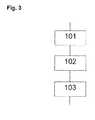
- FIG. 3shows a flow diagram of the inventive method for producing an electrical winding 10, 20 for a dry-type transformer 1, preferably the production of a high-voltage winding 10 for a dry-type transformer.
- method step 101first a winding conductor 11 is wound in several turns to form a coil 15. Thereafter, in step 102, the coil 15 is embedded in a solid insulating body 12, for example by molding the coil 15 with casting resin and curing of the casting resin.
- a coating 14 made of an electrically conductive materialis applied to a surface 13, preferably to the entire surface 13 of the insulating body 12.
Landscapes
- Engineering & Computer Science (AREA)
- Power Engineering (AREA)
- Manufacturing & Machinery (AREA)
- Insulating Of Coils (AREA)
- Coils Of Transformers For General Uses (AREA)
Abstract
Translated fromGerman
Description
Translated fromGermanDie Erfindung betrifft eine elektrische Wicklung für einen Trockentransformator.The invention relates to an electrical winding for a dry-type transformer.
Trockentransformatoren, insbesondere Gießharztransformatoren sind Leistungstransformatoren, die in der Energietechnik zur Transformation von Spannungen bis circa 36 kV auf der Oberspannungsseite eingesetzt werden. Bei solchen Transformatoren sind eine Unterspannungswicklung und eine Oberspannungswicklung koaxial um einen Schenkel eines Kerns angeordnet. Als Unterspannungswicklung wird dabei diejenige Wicklung mit der niedrigeren Spannung, als Oberspannungswicklung diejenige mit der höheren Spannung bezeichnet. Beide Wicklungen sind in ein festes Isoliermaterial eingebettet, im Fall der Oberspannungswicklung wird häufig ein Gießharz dafür verwendet. Solch ein Trockentransformator ist aus der
Soll solch ein Trockentransformator für höhere Spannungen als 36 kV ausgelegt werden, wird dieser deutlich größer ausfallen, als ein solcher einer niedrigeren Spannungsklasse, da insbesondere der Abstand zwischen Oberspannungswicklung und Unterspannungswicklung vergrößert werden muss.If such a dry-type transformer is to be designed for voltages higher than 36 kV, it will be significantly larger than one of a lower voltage class, since in particular the distance between the high-voltage winding and the low-voltage winding must be increased.
Vor diesem Hintergrund ist es Aufgabe der Erfindung, eine elektrische Wicklung für einen Trockentransformator, einen Trockentransformator, sowie ein Verfahren zur Herstellung einer elektrischen Wicklung anzugeben, die eine kompaktere Bauweise eines Trockentransformators erlauben.Against this background, it is an object of the invention to provide an electrical winding for a dry-type transformer, a dry-type transformer, and a method for producing an electrical winding, which allow a more compact design of a dry-type transformer.
Dazu ist eine elektrische Wicklung für einen Trockentransformator vorgesehen, insbesondere eine Oberspannungswicklung, die einen Wicklungsleiter aufweist, der in mehreren Windungen zu einer Spule gewickelt ist. Der Wicklungsleiter kann dabei ein Folienleiter, ein Bandleiter oder ein Drahtleiter sein. Die Spule ist in einen Isolierkörper aus einem festen Isoliermaterial eingebettet. Häufig wird hierfür ein Gießharz verwendet, mit dem die Spule umgossen wird und das nach dem Verguss ausgehärtet wird. Im Ergebnis erhält man eine mechanisch stabile Wicklung in Form eines Hohlzylinders, deren Spule gut vor Umwelteinflüssen geschützt ist. Erfindungsgemäß ist auf einer Oberfläche des Isolierkörpers eine Beschichtung aus einem elektrisch leitfähigen Material aufgebracht. In Fachkreisen und im Sinne der Erfindung wird ein Material als elektrisch leitfähig angesehen, wenn seine spezifische elektrische Leitfähigkeit größer als 10-8 Siemens pro Meter (S/m) ist. Darunter gilt ein Material als Isolator oder als nicht leitend. Die Beschichtung sollte zumindest auf der Innenmantelfläche des Isolierkörpers aufgebracht sein, vorzugsweise auch auf den Stirnflächen. Besonders bevorzugt ist die Beschichtung auf der gesamten Oberfläche des Isolierkörpers aufgebracht, also neben der Innenmantelfläche und den Stirnflächen auch auf der Außenmantelfläche. Durch eine solche Beschichtung wird das elektrische Feld der elektrischen Wicklung weitgehend im Gießharz abgebaut und wird so außerhalb der Wicklung auf eine Größe reduziert, die es erlaubt, dass der Abstand zu anderen Bestandteilen des Transformators wie Kern oder Unterspannungswicklung dadurch geringer ausfallen kann, was eine kompaktere Bauweise ermöglicht.For this purpose, an electrical winding for a dry-type transformer is provided, in particular a high-voltage winding which has a winding conductor which is wound in several turns to form a coil. The winding conductor can thereby a foil conductor, a ribbon conductor or a wire conductor. The coil is embedded in an insulating body made of a solid insulating material. Frequently, a casting resin is used for this, with which the coil is encapsulated and cured after casting. The result is a mechanically stable winding in the form of a hollow cylinder whose coil is well protected against environmental influences. According to the invention, a coating of an electrically conductive material is applied on a surface of the insulating body. In the art and within the meaning of the invention, a material is considered to be electrically conductive if its specific electrical conductivity is greater than 10-8 Siemens per meter (S / m). Including a material is considered insulator or non-conductive. The coating should be applied at least on the inner circumferential surface of the insulating body, preferably also on the end faces. Particularly preferably, the coating is applied to the entire surface of the insulating body, so in addition to the inner circumferential surface and the end faces also on the outer circumferential surface. By such a coating, the electrical field of the electrical winding is largely degraded in the casting resin and is thus reduced outside the winding to a size that allows the distance to other components of the transformer such as core or undervoltage winding can turn out smaller, resulting in a more compact Construction allows.
Bevorzugt ist die Beschichtung aus einem halbleitenden Material. Als halbleitend wird ein Material in Fachkreisen und im Sinne der Erfindung angesehen, wenn sein spezifischer Widerstand größer als 10-8 Siemens pro Meter und kleiner als 106 Siemens pro Meter ist. Da eine elektrisch leitfähige Beschichtung, insbesondere eine der gesamten Oberfläche, einer Wicklung eine Kurzschlusswicklung darstellt, wird in dieser ein Strom fließen, der eine Verlustleistung erzeugt. Mit einer Beschichtung aus einem halbleitenden Material kann diese Verlustleistung begrenzt werden.The coating is preferably made of a semiconducting material. Semiconducting material is considered in the art and within the meaning of the invention if its resistivity is greater than 10-8 Siemens per meter and less than 106 Siemens per meter. Since an electrically conductive coating, in particular one of the entire surface, of a winding represents a short-circuit winding, a current will flow therein, which generates a power loss. With a coating of a semiconductive material, this power loss can be limited.
Geeignete leitende oder halbleitende Beschichtungen sind bekannt unter anderem für die Beschichtung von Kabeln oder Leitern, beispielsweise aus der
Vorzugsweise weist die Beschichtung einen spezifischen Flächenwiderstand, auch Schichtwiderstand genannt, von 102 Ω/□ bis 105 Ω/□ bevorzugt 103 Ω/□ bis 104 Ω/□ auf. Diesen Flächenwiderstand soll die elektrische Wicklung im Neuzustand aufweisen. Durch Alterung, Umwelteinflüsse oder Verschmutzung kann sich dieser verändern. Ein Flächenwiderstand dieser Größenordnung begrenzt einerseits die Verlustleistung besonders effektiv, bietet aber andererseits noch genügend Spielraum bei einer Reduktion des Flächenwiderstands durch Verschmutzung.The coating preferably has a sheet resistivity, also called sheet resistance, of 102 Ω / □ to 105 Ω / □, preferably 103 Ω / □ to 104 Ω / □. This surface resistance should have the electrical winding when new. Aging, environmental influences or pollution can change this. On the one hand, a surface resistance of this magnitude limits the power loss particularly effectively, but on the other hand still offers sufficient scope for reducing the surface resistance due to contamination.
In einer bevorzugten Ausführung der Erfindung ist die Beschichtung durch ein Sprühverfahren aufgebracht. Dies gewährleistet einerseits eine gleichmäßige Schichtdicke und verhindert andererseits Lufteinschlüsse, die zu Teilentladungen führen würden.In a preferred embodiment of the invention, the coating is applied by a spraying process. This ensures on the one hand a uniform layer thickness and on the other hand prevents air pockets, which would lead to partial discharges.
Er wird als vorteilhaft angesehen, wenn die Beschichtung elektrisch geerdet ist. Hierdurch wird das elektrische Feld außerhalb der Wicklung besonders effektiv reduziert.It is considered advantageous if the coating is electrically grounded. As a result, the electric field outside the winding is particularly effectively reduced.
Die Aufgabe wird auch durch einen Trockentransformator gelöst. Ein solcher weist eine um einen Schenkel eines Kerns angeordnete Unterspannungswicklung und eine außen konzentrisch um die Unterspannungswicklung angeordnete Oberspannungswicklung auf. Hierbei ist zumindest die Oberspannungswicklung eine elektrische Wicklung wie vorher beschrieben.The task is also solved by a dry-type transformer. Such has a low-voltage winding arranged around a leg of a core and a high-voltage winding arranged outside concentrically around the low-voltage winding. Here, at least the high-voltage winding is an electrical winding as previously described.
Die Aufgabe wird auch durch ein Verfahren zur Herstellung einer elektrischen Wicklung gelöst. Die Verfahrensschritte dabei sind:
- Zunächst wird ein Wicklungsleiter in mehreren Windungen zu einer Spule gewickelt.
- Die Spule wird anschließend in einen festen Isolierkörper eingebettet, vorzugsweise wird die Spule mit einem Gießharz umgossen, dass danach ausgehärtet wird.
- Auf die Oberfläche des Isolierkörpers wird danach eine Beschichtung aus einem elektrisch leitfähigen Material aufgebracht.
- First, a winding conductor is wound in several turns to a coil.
- The coil is then embedded in a solid insulating body, preferably the coil is encapsulated with a casting resin, which is then cured.
- On the surface of the insulating body is then applied a coating of an electrically conductive material.
Die Beschichtung kann dabei auf die gesamte Oberfläche oder nur auf Teile der Oberfläche, wie bereits beschrieben, aufgebracht werden. Durch ein solches Verfahren ist eine elektrische Wicklung herstellbar, deren elektrisches Feld durch die Beschichtung weitgehend abgeschirmt wird, und die in einem Trockentransformator eingesetzt dadurch eine kompaktere Bauweise ermöglicht. Vorzugsweise ist die Beschichtung ein Lack. Das Aufbringen der Beschichtung kann dabei durch Spritzen, Sprühen, Streichen, Rollen oder als Tauchlackierung erfolgen.The coating can be applied to the entire surface or only to parts of the surface, as already described. By such a method, an electrical winding can be produced, the electric field is largely shielded by the coating, and which used in a dry transformer thereby allows a more compact design. Preferably, the coating is a paint. The application of the coating can be done by spraying, spraying, brushing, rolling or dip coating.
Vorzugsweise ist die Beschichtung aus einem halbleitenden Material.Preferably, the coating is of a semiconductive material.
Besonders bevorzugt ist die Beschichtung in einem Sprühverfahren aufgebracht, wodurch sich eine besonders gleichmäßige Schichtdicke erreichen lässt.Particularly preferably, the coating is applied in a spray process, whereby a particularly uniform layer thickness can be achieved.
Im Folgenden wird die Erfindung anhand der Zeichnungen näher erläutert. Dabei zeigen:
- Figur 1
- eine Halbschnittdarstellung eines bekannten Trockentransformators,
- Figur 2
- eine Halbschnittdarstellung eines erfindungsgemäßen Trockentransformators,
- Figur 3
- ein Ablaufdiagramm des erfindungsgemäßen Verfahrens.
- FIG. 1
- a half-sectional view of a known dry-type transformer,
- FIG. 2
- a half-sectional view of a dry-type transformer according to the invention,
- FIG. 3
- a flow diagram of the method according to the invention.
Einander entsprechende Teile sind in allen Figuren mit den gleichen Bezugszeichen versehen.Corresponding parts are provided in all figures with the same reference numerals.
Die
Die Unterspannungswicklung 20 ist häufig als Folienwicklung ausgeführt. Dabei wird eine dünne Leiterfolie 21 auf einen Wicklungskern zu einer Unterspannungsspule aufgewickelt. Zwischen den einzelnen Wicklungslagen der Leiterfolie ist eine Isolierfolie eingewickelt. Alternativ könnte die Leiterfolie auch mit einer Isolationsschicht versehen sein. Die Unterspannungsspule wird entweder nach dem Wickelvorgang mit Gießharz vergossen. Alternativ kann zwischen die einzelnen Wicklungslagen eine mit Prepreg imprägnierte Zwischenlage 22 eingewickelt werden, die nach dem Wickelvorgang ausgehärtet wird. In beiden Fällen erhält man einen stabilen hohlzylindrischen Wicklungskörper.The low-voltage winding 20 is often designed as a film winding. In this case, a
Die Oberspannungswicklung 51 ist als Scheibenwicklung ausgeführt. Dafür wird ein meist bandförmiger Leiter 11 zunächst in einer Ebene spiralartig um eine Wicklungsachse auf einen Wicklungskern zu einer Scheibenspule gewickelt. Mehrere solcher aufeinander gestapelter Scheibenspulen sind zueinander in Reihe zur Spule 15 verschaltet. Die Spule 15 wird dann derart mit einem Gießharz vergossen, dass die gesamte Spule 15 vom Gießharz umschlossen ist. Die Spule 15 ist dann also in dem Gießharz als Isolierkörper 12 eingebettet.The high-voltage winding 51 is designed as a disk winding. For a usually band-shaped
Die so gebildete hohlzylindrische Oberspannungswicklung 51 hat in der Regel einen größeren Durchmesser, als die Unterspannungswicklung 20 und ist daher vom Kernschenkel 30 aus gesehen außerhalb der Unterspannungswicklung 20 angeordnet.The hollow-cylindrical high-voltage winding 51 thus formed generally has a larger diameter than the low-voltage winding 20 and is therefore arranged outside the low-voltage winding 20 as viewed from the
In dem Luftspalt, der als zylindrischen Hohlraum zwischen Unterspannungswicklung 20 und Oberspannungswicklung 51 entsteht, kann ein Isolierzylinder 23 aus einem elektrisch isolierenden Material angeordnet sein. Er dient einerseits der elektrischen Abschirmung, andererseits zur thermischen Entkopplung der Oberspannungswicklung 51 von der Unterspannungswicklung 20.In the air gap, which is formed as a cylindrical cavity between the low-voltage winding 20 and high-voltage winding 51, an insulating
Das elektrische Feld, das wesentlich durch die an der Oberspannungswicklung 51 anliegende Spannung entsteht, wird hauptsächlich in dem Luftspalt zwischen Oberspannungswicklung 51 und Unterspannungswicklung 20 abgebaut. Der Luftspalt muss demnach entsprechend der an der Oberspannungswicklung 51 anliegenden Spannung dimensioniert werden. Bei höherer Spannung wird auch der Luftspalt entsprechend größer ausfallen. Der Luftspalt dient außerdem der Kühlung der Oberspannungswicklung und Unterspannungswicklung, indem ein Luftstrom entweder durch Konvektion oder elektromechanisch angetrieben durch diesen befördert wird.The electric field, which essentially arises due to the voltage applied to the high-voltage winding 51, is dissipated mainly in the air gap between the high-voltage winding 51 and the low-voltage winding 20. The air gap must therefore be dimensioned according to the voltage applied to the high-voltage winding 51. At higher voltage, the air gap will be correspondingly larger. The air gap also serves to cool the high voltage winding and undervoltage winding by conveying an air stream through either convection or electromechanically driven therethrough.
Außerhalb der Oberspannungswicklung 51 kann außerdem ein leitender Schirm 24, meist aus Metall, angeordnet sein, der geerdet ist und den Trockentransformator 1 berührungssicher macht, da eine Person in der Nähe dadurch nicht mehr mit den hohen elektrischen Feldern der Oberspannungswicklung 51 in Berührung kommen kann. Damit der Schirm 24 keine Kurzschlusswicklung bildet, darf er nicht kreisförmig geschlossen sein, sondern muss einen axialen Spalt aufweisen.Outside the high-voltage winding 51 may also be a
Die
Die Beschichtung 14 bewirkt nun, dass das elektrische Feld der Oberspannungswicklung 10 nahezu vollständig im Isolierkörper 12 der Oberspannungswicklung 10 abgebaut wird. Auf der Oberfläche der Beschichtung 14 wird sich je nach spezifischem Flächenwiderstand eine Spannung einstellen, die in etwa in der Größenordnung der Spannung der Unterspannungswicklung 20 entspricht. Dadurch kann der Spalt zwischen Oberspannungswicklung 10 und Unterspannungswicklung 20 reduziert werden. Dieser Spalt hat nun praktisch keine elektrische Funktion mehr und kann fast ausschließlich auf die erforderliche Kühlleistung dimensioniert werden.The
Vorzugsweise ist die Beschichtung 14 an einer Stelle mit Erdpotential verbunden. Im gezeigten Beispiel der
Die
Claims (11)
Translated fromGermandadurch gekennzeichnet,
dass auf einer Oberfläche (13) des Isolierkörpers (12) eine Beschichtung (14) aus einem elektrisch leitfähigen Material aufgebracht ist.Electric winding (10, 20), in particular high-voltage winding (10), for a dry-type transformer (1) with a winding conductor (11) wound in several turns into a coil (15), the coil (15) being formed into a solid insulating body (10). 12) is embedded,
characterized,
that on a surface (13) of the insulating body (12) has a coating (14) is applied of an electrically conductive material.
dadurch gekennzeichnet,
dass die Beschichtung (14) die Oberfläche (13) des Isolierkörpers (12) vollständig bedeckt.Electric winding (10, 20) according to claim 1,
characterized,
that the coating (14) the surface (13) of the insulating body (12) completely covered.
dadurch gekennzeichnet,
dass die Beschichtung (14) aus einem halbleitenden Material ist.Winding (10, 20) according to claim 1 or 2,
characterized,
that the coating (14) is made of a semiconductive material.
dadurch gekennzeichnet,
dass der Oberflächenwiderstand der Beschichtung (14) 102 Ω/□ bis 105 Ω/□ bevorzugt 103 Ω/□ bis 104Ω/□ beträgt.Electric winding (10, 20) according to one of claims 1 to 3,
characterized,
that the surface resistance of the coating (14) 102 Ω / □ to 10 Ω5 / □ preferably 103 Ω / □ to 10 Ω4 / m □.
dadurch gekennzeichnet,
dass die Beschichtung (14) durch ein Sprühverfahren aufgebracht ist.Electric winding (10, 20) according to one of claims 1 to 4,
characterized,
that the coating (14) is applied by a spray process.
dadurch gekennzeichnet,
dass die Beschichtung (14) geerdet ist.Electric winding (10, 20) according to one of claims 1 to 5,
characterized,
that the coating (14) is grounded.
dadurch gekennzeichnet,
dass die Beschichtung (14) auf die gesamte Oberfläche (13) des Isolierkörpers (12) aufgebracht wird.Method according to claim 8,
characterized,
that the coating (14) (13) of the insulating body (12) is applied to the entire surface.
dadurch gekennzeichnet,
dass die Beschichtung (14) aus einem halbleitenden Material ist.Method according to one of claims 8 or 9,
characterized,
that the coating (14) is made of a semiconductive material.
dadurch gekennzeichnet,
dass die Beschichtung (14) in einem Sprühverfahren aufgebracht wird.Method according to one of claims 8 to 10,
characterized,
that the coating (14) is applied in a spraying process.
Priority Applications (3)
| Application Number | Priority Date | Filing Date | Title |
|---|---|---|---|
| EP15185886.7AEP3144944A1 (en) | 2015-09-18 | 2015-09-18 | Electrical winding, dry transformer with such an electrical winding, and method for production of an electrical winding |
| BR102016020804ABR102016020804A8 (en) | 2015-09-18 | 2016-09-09 | ELECTRIC WINDING, DRY TRANSFORMER WITH THIS ELECTRIC WINDING AND PROCESS FOR PRODUCING AN ELECTRIC WINDING |
| CN201610821938.9ACN107039159A (en) | 2015-09-18 | 2016-09-13 | Electric winding, the dry-type transformer with electric winding and the method for manufacturing electric winding |
Applications Claiming Priority (1)
| Application Number | Priority Date | Filing Date | Title |
|---|---|---|---|
| EP15185886.7AEP3144944A1 (en) | 2015-09-18 | 2015-09-18 | Electrical winding, dry transformer with such an electrical winding, and method for production of an electrical winding |
Publications (1)
| Publication Number | Publication Date |
|---|---|
| EP3144944A1true EP3144944A1 (en) | 2017-03-22 |
Family
ID=54150329
Family Applications (1)
| Application Number | Title | Priority Date | Filing Date |
|---|---|---|---|
| EP15185886.7ACeasedEP3144944A1 (en) | 2015-09-18 | 2015-09-18 | Electrical winding, dry transformer with such an electrical winding, and method for production of an electrical winding |
Country Status (3)
| Country | Link |
|---|---|
| EP (1) | EP3144944A1 (en) |
| CN (1) | CN107039159A (en) |
| BR (1) | BR102016020804A8 (en) |
Cited By (6)
| Publication number | Priority date | Publication date | Assignee | Title |
|---|---|---|---|---|
| DE102016202385A1 (en) | 2016-02-17 | 2017-08-17 | Siemens Aktiengesellschaft | Compact dry-type transformer with an electrical winding and method for producing an electrical winding |
| DE102016202391A1 (en) | 2016-02-17 | 2017-08-31 | Siemens Aktiengesellschaft | Compact dry-type transformer with an electrical winding and method for producing an electrical winding |
| DE102017221593A1 (en)* | 2017-11-30 | 2019-06-06 | Siemens Aktiengesellschaft | winding arrangement |
| WO2020035224A1 (en) | 2018-08-14 | 2020-02-20 | Siemens Aktiengesellschaft | Winding arrangement with field smoothing and armouring |
| EP4181160A1 (en)* | 2021-11-16 | 2023-05-17 | Huawei Digital Power Technologies Co., Ltd. | Transformer and power equipment |
| EP4471814A4 (en)* | 2022-03-07 | 2025-05-07 | Huawei Digital Power Technologies Co., Ltd. | HIGH VOLTAGE TRANSFORMER ASSEMBLY, AND TRANSFORMER AND POWER SUPPLY DEVICE |
Families Citing this family (2)
| Publication number | Priority date | Publication date | Assignee | Title |
|---|---|---|---|---|
| EP3791413B1 (en)* | 2018-06-07 | 2023-08-02 | Siemens Energy Global GmbH & Co. KG | Shielded coil assemblies and methods for dry-type transformers |
| DE102018212144A1 (en)* | 2018-07-20 | 2020-01-23 | Siemens Aktiengesellschaft | Arrangement comprising a coiled conductor strand and method for producing such an arrangement |
Citations (8)
| Publication number | Priority date | Publication date | Assignee | Title |
|---|---|---|---|---|
| GB1156369A (en)* | 1966-04-08 | 1969-06-25 | Gen Electric | Coated Electrostatic Shields for Electrical Apparatus |
| DE2826266A1 (en)* | 1978-06-15 | 1979-12-20 | Transformatoren Union Ag | Multiphase transformer with high and low-tension voltage windings - which are all embedded together with leads and terminals in a single metallised resinous casting (NL 18.12.79) |
| EP0061608A1 (en)* | 1981-04-01 | 1982-10-06 | Smit Transformatoren B.V. | Air-cooled dry type transformer or inductance |
| FR2784787A1 (en)* | 1998-10-20 | 2000-04-21 | France Transfo Sa | Dry power transformer construction energy distributor having resin section low voltage applied and outer cover and protruding cooling fins. |
| EP1133779B1 (en) | 1998-11-25 | 2005-03-16 | Siemens Aktiengesellschaft | Transformer, especially a resin-encapsulated transformer |
| DE102005018615A1 (en) | 2004-05-17 | 2005-12-08 | Merck Patent Gmbh | Electrically conductive pigment for use in e.g. paint, has flake-form substrates coated with conductive layer, where number-weighted mean particle area of pigment is greater than or equal to one hundred and fifty square meter |
| US20150243409A1 (en) | 2014-02-25 | 2015-08-27 | Essex Group, Inc. | Insulated winding wire containing semi-conductive layers |
| EP3125260A1 (en)* | 2015-07-31 | 2017-02-01 | ABB Technology AG | Transformer for a modular, power electronic converter |
Family Cites Families (1)
| Publication number | Priority date | Publication date | Assignee | Title |
|---|---|---|---|---|
| SE0003037D0 (en)* | 2000-08-29 | 2000-08-29 | Abb Ab | Electric machine |
- 2015
- 2015-09-18EPEP15185886.7Apatent/EP3144944A1/ennot_activeCeased
- 2016
- 2016-09-09BRBR102016020804Apatent/BR102016020804A8/ennot_activeApplication Discontinuation
- 2016-09-13CNCN201610821938.9Apatent/CN107039159A/enactivePending
Patent Citations (8)
| Publication number | Priority date | Publication date | Assignee | Title |
|---|---|---|---|---|
| GB1156369A (en)* | 1966-04-08 | 1969-06-25 | Gen Electric | Coated Electrostatic Shields for Electrical Apparatus |
| DE2826266A1 (en)* | 1978-06-15 | 1979-12-20 | Transformatoren Union Ag | Multiphase transformer with high and low-tension voltage windings - which are all embedded together with leads and terminals in a single metallised resinous casting (NL 18.12.79) |
| EP0061608A1 (en)* | 1981-04-01 | 1982-10-06 | Smit Transformatoren B.V. | Air-cooled dry type transformer or inductance |
| FR2784787A1 (en)* | 1998-10-20 | 2000-04-21 | France Transfo Sa | Dry power transformer construction energy distributor having resin section low voltage applied and outer cover and protruding cooling fins. |
| EP1133779B1 (en) | 1998-11-25 | 2005-03-16 | Siemens Aktiengesellschaft | Transformer, especially a resin-encapsulated transformer |
| DE102005018615A1 (en) | 2004-05-17 | 2005-12-08 | Merck Patent Gmbh | Electrically conductive pigment for use in e.g. paint, has flake-form substrates coated with conductive layer, where number-weighted mean particle area of pigment is greater than or equal to one hundred and fifty square meter |
| US20150243409A1 (en) | 2014-02-25 | 2015-08-27 | Essex Group, Inc. | Insulated winding wire containing semi-conductive layers |
| EP3125260A1 (en)* | 2015-07-31 | 2017-02-01 | ABB Technology AG | Transformer for a modular, power electronic converter |
Cited By (8)
| Publication number | Priority date | Publication date | Assignee | Title |
|---|---|---|---|---|
| DE102016202385A1 (en) | 2016-02-17 | 2017-08-17 | Siemens Aktiengesellschaft | Compact dry-type transformer with an electrical winding and method for producing an electrical winding |
| WO2017140577A1 (en)* | 2016-02-17 | 2017-08-24 | Siemens Aktiengesellschaft | Compact dry-type transformer comprising an electrical winding, and method for manufacturing an electrical winding |
| DE102016202391A1 (en) | 2016-02-17 | 2017-08-31 | Siemens Aktiengesellschaft | Compact dry-type transformer with an electrical winding and method for producing an electrical winding |
| US11532429B2 (en) | 2016-02-17 | 2022-12-20 | Siemens Energy Global GmbH & Co. KG | Dry-type transformer |
| DE102017221593A1 (en)* | 2017-11-30 | 2019-06-06 | Siemens Aktiengesellschaft | winding arrangement |
| WO2020035224A1 (en) | 2018-08-14 | 2020-02-20 | Siemens Aktiengesellschaft | Winding arrangement with field smoothing and armouring |
| EP4181160A1 (en)* | 2021-11-16 | 2023-05-17 | Huawei Digital Power Technologies Co., Ltd. | Transformer and power equipment |
| EP4471814A4 (en)* | 2022-03-07 | 2025-05-07 | Huawei Digital Power Technologies Co., Ltd. | HIGH VOLTAGE TRANSFORMER ASSEMBLY, AND TRANSFORMER AND POWER SUPPLY DEVICE |
Also Published As
| Publication number | Publication date |
|---|---|
| BR102016020804A8 (en) | 2023-04-25 |
| BR102016020804A2 (en) | 2017-03-28 |
| CN107039159A (en) | 2017-08-11 |
Similar Documents
| Publication | Publication Date | Title |
|---|---|---|
| EP3144944A1 (en) | Electrical winding, dry transformer with such an electrical winding, and method for production of an electrical winding | |
| DE69728972T2 (en) | TRANSFORMER / REACTOR | |
| DE102012204052B4 (en) | High-voltage bushing with conductive inserts for direct voltage and method for their production | |
| EP2428967B1 (en) | Transformer coil | |
| EP3363029B1 (en) | Compact dry-type transformer comprising an electric winding, and method for manufacturing an electric winding | |
| EP3639282B1 (en) | Pluggable high-voltage bushing and electrical device having pluggable high-voltage bushing | |
| DE19856123C2 (en) | Hollow insulator | |
| CH709972B1 (en) | Electrical cable. | |
| WO2017134040A1 (en) | Shielding ring for a transformer coil | |
| EP3001435B1 (en) | Dry transformer core | |
| EP2661756A1 (en) | Transformer winding with cooling channel | |
| EP1958217A2 (en) | Electrical winding | |
| EP2715743B1 (en) | Electric component for a high-voltage system | |
| EP0133220A2 (en) | Electric conductor | |
| EP3711071B1 (en) | High-voltage feedthrough | |
| EP2431983A1 (en) | High voltage bushing and method for manufacturing same | |
| WO2001080254A1 (en) | Module with surge arrester for a high-voltage system | |
| WO2019020311A1 (en) | PLUG-IN HIGH VOLTAGE IMPLEMENTATION AND ELECTRICAL DEVICE WITH STICKABLE HIGH VOLTAGE IMPLEMENTATION | |
| DE1665075B1 (en) | Method of insulating an electrical object | |
| WO2017140577A1 (en) | Compact dry-type transformer comprising an electrical winding, and method for manufacturing an electrical winding | |
| EP2515313A1 (en) | High voltage feed-through | |
| EP3410451B1 (en) | Shield ring for a transformer coil | |
| EP3001437B1 (en) | Feedthrough system | |
| DE4204092C2 (en) | Coil former for at least one winding chamber for electrical material to be wound, in particular for a high-voltage transformer, and high-voltage transformer | |
| EP3185251B1 (en) | High voltage feed-through with voltage divider pickup and production method for a high-voltage feed-through with voltage divider pickup |
Legal Events
| Date | Code | Title | Description |
|---|---|---|---|
| PUAI | Public reference made under article 153(3) epc to a published international application that has entered the european phase | Free format text:ORIGINAL CODE: 0009012 | |
| AK | Designated contracting states | Kind code of ref document:A1 Designated state(s):AL AT BE BG CH CY CZ DE DK EE ES FI FR GB GR HR HU IE IS IT LI LT LU LV MC MK MT NL NO PL PT RO RS SE SI SK SM TR | |
| AX | Request for extension of the european patent | Extension state:BA ME | |
| RAP1 | Party data changed (applicant data changed or rights of an application transferred) | Owner name:SIEMENS AKTIENGESELLSCHAFT | |
| 17P | Request for examination filed | Effective date:20170919 | |
| RBV | Designated contracting states (corrected) | Designated state(s):AL AT BE BG CH CY CZ DE DK EE ES FI FR GB GR HR HU IE IS IT LI LT LU LV MC MK MT NL NO PL PT RO RS SE SI SK SM TR | |
| 17Q | First examination report despatched | Effective date:20190703 | |
| RAP1 | Party data changed (applicant data changed or rights of an application transferred) | Owner name:SIEMENS ENERGY GLOBAL GMBH & CO. KG | |
| STAA | Information on the status of an ep patent application or granted ep patent | Free format text:STATUS: THE APPLICATION HAS BEEN REFUSED | |
| 18R | Application refused | Effective date:20201220 |