EP3142604B1 - Transcatheter valve with paravalvular leak sealing ring - Google Patents
Transcatheter valve with paravalvular leak sealing ringDownload PDFInfo
- Publication number
- EP3142604B1 EP3142604B1EP15725169.5AEP15725169AEP3142604B1EP 3142604 B1EP3142604 B1EP 3142604B1EP 15725169 AEP15725169 AEP 15725169AEP 3142604 B1EP3142604 B1EP 3142604B1
- Authority
- EP
- European Patent Office
- Prior art keywords
- tube
- covering
- stent
- heart valve
- valve
- Prior art date
- Legal status (The legal status is an assumption and is not a legal conclusion. Google has not performed a legal analysis and makes no representation as to the accuracy of the status listed.)
- Active
Links
Images


Classifications
- A—HUMAN NECESSITIES
- A61—MEDICAL OR VETERINARY SCIENCE; HYGIENE
- A61F—FILTERS IMPLANTABLE INTO BLOOD VESSELS; PROSTHESES; DEVICES PROVIDING PATENCY TO, OR PREVENTING COLLAPSING OF, TUBULAR STRUCTURES OF THE BODY, e.g. STENTS; ORTHOPAEDIC, NURSING OR CONTRACEPTIVE DEVICES; FOMENTATION; TREATMENT OR PROTECTION OF EYES OR EARS; BANDAGES, DRESSINGS OR ABSORBENT PADS; FIRST-AID KITS
- A61F2/00—Filters implantable into blood vessels; Prostheses, i.e. artificial substitutes or replacements for parts of the body; Appliances for connecting them with the body; Devices providing patency to, or preventing collapsing of, tubular structures of the body, e.g. stents
- A61F2/02—Prostheses implantable into the body
- A61F2/24—Heart valves ; Vascular valves, e.g. venous valves; Heart implants, e.g. passive devices for improving the function of the native valve or the heart muscle; Transmyocardial revascularisation [TMR] devices; Valves implantable in the body
- A61F2/2412—Heart valves ; Vascular valves, e.g. venous valves; Heart implants, e.g. passive devices for improving the function of the native valve or the heart muscle; Transmyocardial revascularisation [TMR] devices; Valves implantable in the body with soft flexible valve members, e.g. tissue valves shaped like natural valves
- A61F2/2418—Scaffolds therefor, e.g. support stents
- A—HUMAN NECESSITIES
- A61—MEDICAL OR VETERINARY SCIENCE; HYGIENE
- A61F—FILTERS IMPLANTABLE INTO BLOOD VESSELS; PROSTHESES; DEVICES PROVIDING PATENCY TO, OR PREVENTING COLLAPSING OF, TUBULAR STRUCTURES OF THE BODY, e.g. STENTS; ORTHOPAEDIC, NURSING OR CONTRACEPTIVE DEVICES; FOMENTATION; TREATMENT OR PROTECTION OF EYES OR EARS; BANDAGES, DRESSINGS OR ABSORBENT PADS; FIRST-AID KITS
- A61F2/00—Filters implantable into blood vessels; Prostheses, i.e. artificial substitutes or replacements for parts of the body; Appliances for connecting them with the body; Devices providing patency to, or preventing collapsing of, tubular structures of the body, e.g. stents
- A61F2/02—Prostheses implantable into the body
- A61F2/24—Heart valves ; Vascular valves, e.g. venous valves; Heart implants, e.g. passive devices for improving the function of the native valve or the heart muscle; Transmyocardial revascularisation [TMR] devices; Valves implantable in the body
- A61F2/2427—Devices for manipulating or deploying heart valves during implantation
- A61F2/2436—Deployment by retracting a sheath
- A—HUMAN NECESSITIES
- A61—MEDICAL OR VETERINARY SCIENCE; HYGIENE
- A61F—FILTERS IMPLANTABLE INTO BLOOD VESSELS; PROSTHESES; DEVICES PROVIDING PATENCY TO, OR PREVENTING COLLAPSING OF, TUBULAR STRUCTURES OF THE BODY, e.g. STENTS; ORTHOPAEDIC, NURSING OR CONTRACEPTIVE DEVICES; FOMENTATION; TREATMENT OR PROTECTION OF EYES OR EARS; BANDAGES, DRESSINGS OR ABSORBENT PADS; FIRST-AID KITS
- A61F2/00—Filters implantable into blood vessels; Prostheses, i.e. artificial substitutes or replacements for parts of the body; Appliances for connecting them with the body; Devices providing patency to, or preventing collapsing of, tubular structures of the body, e.g. stents
- A61F2/02—Prostheses implantable into the body
- A61F2/24—Heart valves ; Vascular valves, e.g. venous valves; Heart implants, e.g. passive devices for improving the function of the native valve or the heart muscle; Transmyocardial revascularisation [TMR] devices; Valves implantable in the body
- A61F2/2412—Heart valves ; Vascular valves, e.g. venous valves; Heart implants, e.g. passive devices for improving the function of the native valve or the heart muscle; Transmyocardial revascularisation [TMR] devices; Valves implantable in the body with soft flexible valve members, e.g. tissue valves shaped like natural valves
- A—HUMAN NECESSITIES
- A61—MEDICAL OR VETERINARY SCIENCE; HYGIENE
- A61F—FILTERS IMPLANTABLE INTO BLOOD VESSELS; PROSTHESES; DEVICES PROVIDING PATENCY TO, OR PREVENTING COLLAPSING OF, TUBULAR STRUCTURES OF THE BODY, e.g. STENTS; ORTHOPAEDIC, NURSING OR CONTRACEPTIVE DEVICES; FOMENTATION; TREATMENT OR PROTECTION OF EYES OR EARS; BANDAGES, DRESSINGS OR ABSORBENT PADS; FIRST-AID KITS
- A61F2/00—Filters implantable into blood vessels; Prostheses, i.e. artificial substitutes or replacements for parts of the body; Appliances for connecting them with the body; Devices providing patency to, or preventing collapsing of, tubular structures of the body, e.g. stents
- A61F2/02—Prostheses implantable into the body
- A61F2/24—Heart valves ; Vascular valves, e.g. venous valves; Heart implants, e.g. passive devices for improving the function of the native valve or the heart muscle; Transmyocardial revascularisation [TMR] devices; Valves implantable in the body
- A61F2/2472—Devices for testing
- A—HUMAN NECESSITIES
- A61—MEDICAL OR VETERINARY SCIENCE; HYGIENE
- A61F—FILTERS IMPLANTABLE INTO BLOOD VESSELS; PROSTHESES; DEVICES PROVIDING PATENCY TO, OR PREVENTING COLLAPSING OF, TUBULAR STRUCTURES OF THE BODY, e.g. STENTS; ORTHOPAEDIC, NURSING OR CONTRACEPTIVE DEVICES; FOMENTATION; TREATMENT OR PROTECTION OF EYES OR EARS; BANDAGES, DRESSINGS OR ABSORBENT PADS; FIRST-AID KITS
- A61F2210/00—Particular material properties of prostheses classified in groups A61F2/00 - A61F2/26 or A61F2/82 or A61F9/00 or A61F11/00 or subgroups thereof
- A61F2210/0014—Particular material properties of prostheses classified in groups A61F2/00 - A61F2/26 or A61F2/82 or A61F9/00 or A61F11/00 or subgroups thereof using shape memory or superelastic materials, e.g. nitinol
- A—HUMAN NECESSITIES
- A61—MEDICAL OR VETERINARY SCIENCE; HYGIENE
- A61F—FILTERS IMPLANTABLE INTO BLOOD VESSELS; PROSTHESES; DEVICES PROVIDING PATENCY TO, OR PREVENTING COLLAPSING OF, TUBULAR STRUCTURES OF THE BODY, e.g. STENTS; ORTHOPAEDIC, NURSING OR CONTRACEPTIVE DEVICES; FOMENTATION; TREATMENT OR PROTECTION OF EYES OR EARS; BANDAGES, DRESSINGS OR ABSORBENT PADS; FIRST-AID KITS
- A61F2210/00—Particular material properties of prostheses classified in groups A61F2/00 - A61F2/26 or A61F2/82 or A61F9/00 or A61F11/00 or subgroups thereof
- A61F2210/0061—Particular material properties of prostheses classified in groups A61F2/00 - A61F2/26 or A61F2/82 or A61F9/00 or A61F11/00 or subgroups thereof swellable
- A—HUMAN NECESSITIES
- A61—MEDICAL OR VETERINARY SCIENCE; HYGIENE
- A61F—FILTERS IMPLANTABLE INTO BLOOD VESSELS; PROSTHESES; DEVICES PROVIDING PATENCY TO, OR PREVENTING COLLAPSING OF, TUBULAR STRUCTURES OF THE BODY, e.g. STENTS; ORTHOPAEDIC, NURSING OR CONTRACEPTIVE DEVICES; FOMENTATION; TREATMENT OR PROTECTION OF EYES OR EARS; BANDAGES, DRESSINGS OR ABSORBENT PADS; FIRST-AID KITS
- A61F2220/00—Fixations or connections for prostheses classified in groups A61F2/00 - A61F2/26 or A61F2/82 or A61F9/00 or A61F11/00 or subgroups thereof
- A61F2220/0025—Connections or couplings between prosthetic parts, e.g. between modular parts; Connecting elements
- A61F2220/0075—Connections or couplings between prosthetic parts, e.g. between modular parts; Connecting elements sutured, ligatured or stitched, retained or tied with a rope, string, thread, wire or cable
- A—HUMAN NECESSITIES
- A61—MEDICAL OR VETERINARY SCIENCE; HYGIENE
- A61F—FILTERS IMPLANTABLE INTO BLOOD VESSELS; PROSTHESES; DEVICES PROVIDING PATENCY TO, OR PREVENTING COLLAPSING OF, TUBULAR STRUCTURES OF THE BODY, e.g. STENTS; ORTHOPAEDIC, NURSING OR CONTRACEPTIVE DEVICES; FOMENTATION; TREATMENT OR PROTECTION OF EYES OR EARS; BANDAGES, DRESSINGS OR ABSORBENT PADS; FIRST-AID KITS
- A61F2230/00—Geometry of prostheses classified in groups A61F2/00 - A61F2/26 or A61F2/82 or A61F9/00 or A61F11/00 or subgroups thereof
- A61F2230/0002—Two-dimensional shapes, e.g. cross-sections
- A61F2230/0004—Rounded shapes, e.g. with rounded corners
- A61F2230/001—Figure-8-shaped, e.g. hourglass-shaped
- A—HUMAN NECESSITIES
- A61—MEDICAL OR VETERINARY SCIENCE; HYGIENE
- A61F—FILTERS IMPLANTABLE INTO BLOOD VESSELS; PROSTHESES; DEVICES PROVIDING PATENCY TO, OR PREVENTING COLLAPSING OF, TUBULAR STRUCTURES OF THE BODY, e.g. STENTS; ORTHOPAEDIC, NURSING OR CONTRACEPTIVE DEVICES; FOMENTATION; TREATMENT OR PROTECTION OF EYES OR EARS; BANDAGES, DRESSINGS OR ABSORBENT PADS; FIRST-AID KITS
- A61F2230/00—Geometry of prostheses classified in groups A61F2/00 - A61F2/26 or A61F2/82 or A61F9/00 or A61F11/00 or subgroups thereof
- A61F2230/0002—Two-dimensional shapes, e.g. cross-sections
- A61F2230/0017—Angular shapes
- A61F2230/0019—Angular shapes rectangular
- A—HUMAN NECESSITIES
- A61—MEDICAL OR VETERINARY SCIENCE; HYGIENE
- A61F—FILTERS IMPLANTABLE INTO BLOOD VESSELS; PROSTHESES; DEVICES PROVIDING PATENCY TO, OR PREVENTING COLLAPSING OF, TUBULAR STRUCTURES OF THE BODY, e.g. STENTS; ORTHOPAEDIC, NURSING OR CONTRACEPTIVE DEVICES; FOMENTATION; TREATMENT OR PROTECTION OF EYES OR EARS; BANDAGES, DRESSINGS OR ABSORBENT PADS; FIRST-AID KITS
- A61F2230/00—Geometry of prostheses classified in groups A61F2/00 - A61F2/26 or A61F2/82 or A61F9/00 or A61F11/00 or subgroups thereof
- A61F2230/0002—Two-dimensional shapes, e.g. cross-sections
- A61F2230/0028—Shapes in the form of latin or greek characters
- A61F2230/0034—D-shaped
- A—HUMAN NECESSITIES
- A61—MEDICAL OR VETERINARY SCIENCE; HYGIENE
- A61F—FILTERS IMPLANTABLE INTO BLOOD VESSELS; PROSTHESES; DEVICES PROVIDING PATENCY TO, OR PREVENTING COLLAPSING OF, TUBULAR STRUCTURES OF THE BODY, e.g. STENTS; ORTHOPAEDIC, NURSING OR CONTRACEPTIVE DEVICES; FOMENTATION; TREATMENT OR PROTECTION OF EYES OR EARS; BANDAGES, DRESSINGS OR ABSORBENT PADS; FIRST-AID KITS
- A61F2230/00—Geometry of prostheses classified in groups A61F2/00 - A61F2/26 or A61F2/82 or A61F9/00 or A61F11/00 or subgroups thereof
- A61F2230/0063—Three-dimensional shapes
- A61F2230/0073—Quadric-shaped
- A61F2230/0078—Quadric-shaped hyperboloidal
- A—HUMAN NECESSITIES
- A61—MEDICAL OR VETERINARY SCIENCE; HYGIENE
- A61F—FILTERS IMPLANTABLE INTO BLOOD VESSELS; PROSTHESES; DEVICES PROVIDING PATENCY TO, OR PREVENTING COLLAPSING OF, TUBULAR STRUCTURES OF THE BODY, e.g. STENTS; ORTHOPAEDIC, NURSING OR CONTRACEPTIVE DEVICES; FOMENTATION; TREATMENT OR PROTECTION OF EYES OR EARS; BANDAGES, DRESSINGS OR ABSORBENT PADS; FIRST-AID KITS
- A61F2250/00—Special features of prostheses classified in groups A61F2/00 - A61F2/26 or A61F2/82 or A61F9/00 or A61F11/00 or subgroups thereof
- A61F2250/0058—Additional features; Implant or prostheses properties not otherwise provided for
- A61F2250/0069—Sealing means
Definitions
- the present disclosurerelates to heart valve replacement and, in particular, to collapsible prosthetic heart valves. More particularly, the present disclosure relates to collapsible prosthetic transcatheter heart valves which minimize or reduce paravalvular leaks.
- Prosthetic heart valves that are collapsible to a relatively small circumferential sizecan be delivered into a patient less invasively than valves that are not collapsible.
- a collapsible valvemay be delivered into a patient via a tube-like delivery apparatus such as a catheter, a trocar, a laparoscopic instrument, or the like. This collapsibility can avoid the need for a more invasive procedure such as full open-chest, open-heart surgery.
- Collapsible prosthetic heart valvestypically take the form of a valve structure mounted on a stent.
- a stentThere are two common types of stents on which the valve structures are ordinarily mounted: a self-expanding stent and a balloon-expandable stent.
- a self-expanding stentTo place such valves into a delivery apparatus and ultimately into a patient, the valve is first collapsed or crimped to reduce its circumferential size.
- the prosthetic valveWhen a collapsed prosthetic valve has reached the desired implant site in the patient (e.g ., at or near the annulus of the patient's heart valve that is to be replaced by the prosthetic valve), the prosthetic valve can be deployed or released from the delivery apparatus and re-expanded to full operating size.
- thisgenerally involves releasing the valve, assuring its proper location, and then expanding a balloon positioned within the valve stent.
- the stentautomatically expands as a sheath covering the valve is withdrawn.
- WO 2014/121042 A1which was published after the declared priority date of the present application, discloses a transcatheter valve prosthesis which includes an expandable tubular stent, a prosthetic valve within the stent, and an anti-paravalvular leakage component coupled to and encircling the tubular stent.
- CN103705315Adiscloses an aortic valve stent capable of preventing perivalvular leakage.
- a prosthetic heart valveincludes a collapsible and expandable stent extending from an inflow end to an outflow end, and a plurality of prosthetic valve leaflets coupled to the stent. Each leaflet may have a leaflet belly.
- the prosthetic heart valvemay include a sealing ring coupled to the inflow end of the stent, the sealing ring comprising a tube extending circumferentially around the inflow end of the stent, wherein the tube is formed from a wire coiled into a repeating shape such that the tube is collapsible.
- the sealing ringmay be axially offset from the leaflet belly when the stent is in a collapsed condition.
- a prosthetic heart valveincludes a collapsible and expandable stent extending from an inflow end to an outflow end and a plurality of prosthetic valve leaflets coupled to the stent. Each leaflet may have a leaflet belly.
- the prosthetic heart valvemay include a sealing ring coupled to the inflow end of the stent, the sealing ring comprising a tube extending circumferentially around the inflow end of the stent, a covering at least partially surrounding the tube, and at least one of a first filler positioned within the tube and a second filler positioned between the tube and the covering.
- the sealing ringmay be axially offset from the leaflet belly when the stent is in a collapsed condition.
- a prosthetic heart valveincludes a collapsible and expandable stent extending from an inflow end to an outflow end and a plurality of prosthetic valve leaflets coupled to the stent. Each leaflet may have a leaflet belly.
- the prosthetic heart valvemay also include a sealing ring coupled to the inflow end of the stent, the sealing ring comprising a tube extending circumferentially around the inflow end of the stent and a covering at least partially surrounding the tube, wherein the covering has a first end and a second end, the first end coupled to the stent by a first thread.
- the sealing ringmay be axially offset from the leaflet belly when the stent is in a collapsed condition.
- the term "inflow end,” when used in connection with a prosthetic heart valve,refers to the end of the heart valve through which blood enters when the valve is functioning as intended.
- the term “outflow end,” when used in connection with a prosthetic heart valve,refers to the end of the heart valve through which blood exits when the valve is functioning as intended.
- the terms “generally,” “substantially,” and “about”are intended to mean that slight deviations from absolute are included within the scope of the term so modified.
- Like numbersrefer to similar or identical elements throughout.
- the lengthwise or axial directionrefers to a direction along a longitudinal axis passing through the center of the stent or heart valve.
- the circumferential directionrefers to a direction extending along the circumference of the prosthetic heart valve.
- FIG. 1shows one such collapsible stent-supported prosthetic heart valve 100 in an expanded condition.
- the prosthetic heart valve 100is designed to replace the function of a native aortic valve of a patient.
- the prosthetic heart valve 100includes a stent constructed as a frame 102.
- the stent 102extends in a lengthwise or axial direction L from an inflow or annulus end 130 to an outflow or aortic end 132, and includes an annulus section 104 adjacent the inflow end 130 and an aortic section 142 adjacent the outflow end 132.
- the annulus section 104has a relatively small cross section in the expanded condition, while the aortic section 142 has a relatively large cross section in the expanded condition.
- the annulus section 104may be in the form of a cylinder having a substantially constant diameter along its length.
- a transition section 141may taper outwardly from the annulus section 104 to the aortic section 142.
- Each of the sections of the stent 102includes a plurality of cells 112 connected to one another in one or more annular rows around the stent 102.
- the annulus section 104may have two annular rows of complete cells 112 and the aortic section 142 and the transition section 141 may each have one or more annular rows of complete or partial cells 112.
- the cells 112 in the aortic section 142may be larger than the cells 112 in the annulus section 104.
- the larger cells 112 in the aortic section 142may better enable the prosthetic valve 100 to be positioned without the stent structure 102 interfering with blood flow to the coronary arteries.
- the stent 102elongates in the lengthwise direction L as cells 112 collapse when the stent 102 is transitioned from the expanded condition to the collapsed condition.
- the stent 102may include one or more retaining elements 118 at the outflow end 132, the retaining elements 118 being sized and shaped to cooperate with retaining structures provided on a deployment device (not shown).
- the engagement of the retaining elements 118 with the retaining structures on the deployment devicemay help maintain the prosthetic heart valve 100 in assembled relationship with the deployment device, minimize longitudinal movement of the prosthetic heart valve relative to the deployment device during unsheathing or resheathing procedures, and help prevent rotation of the prosthetic heart valve relative to the deployment device as the deployment device is advanced to the target location and during deployment.
- One such deployment deviceis shown in U.S. Patent Publication No. 2012/0078352 .
- the stent 102may also include a plurality of commissure points 116 for mounting the commissures (not identified) of the valve assembly discussed below to the stent 102.
- the commissure points 116may lay at the intersection of four cells 112, two of the cells 112 being adjacent one another in the same annular row, and the other two cells 112 being in different annular rows and lying in end to end relationship.
- the commissure points 116may be positioned entirely within the annulus section 104 or at the juncture of annulus section 104 and the transition section 141.
- the commissure points 116may include one or more eyelets which facilitate the suturing of the leaflet commissure to the stent.
- the prosthetic heart valve 100includes a valve assembly 140 positioned in the annulus section 104.
- the valve assemblyincludes three leaflets 108. Two leaflets join one another at each of three commissures.
- the valve assembly 140may be mounted to the stent 102 by suturing the commissures of the leaflets 108 to the commissure points 116 and suturing other portions of the valve assembly 140 to the stent 102, or by other methods known in the art.
- the valve assembly 140may include a cuff 106 and a plurality of leaflets 108 which collectively function as a one way valve by coapting with one another.
- FIG. 1illustrates a prosthetic heart valve for replacing a native tricuspid valve, such as the aortic valve. Accordingly, the prosthetic heart valve 100 is shown in FIG. 1 with three leaflets 108, as well as three commissure points 116. However, it will be appreciated that the prosthetic heart valves according to aspects of the disclosure may have a greater or lesser number of leaflets 108 and commissure points 116.
- the leaflets 108define a leaflet belly B, indicated with broken lines in FIG. 1 .
- the leaflet belly Bis the portions of valve assembly 140 above which leaflets 108 are free to move radially inwardly to coapt with one another along their free edges. With this configuration, the valve assembly 140 is particularly thick at points at or above leaflet belly B. As such, any additional material axially aligned with valve assembly 140 above (or distal to) leaflet belly B may add significantly to the crimp profile of the valve 100.
- the cuff 106is shown in FIG. 1 as being disposed on the lumenal or inner surface of the annulus section 104, the cuff 106 may be disposed on the ablumenal or outer surface of annulus section 104, or may cover all or part of either or both of the lumenal and ablumenal surfaces of the annulus section 104.
- the entirety of the valve assembly 140including the leaflet commissures, is positioned in the annulus section 104 of the stent 102. When opened, the leaflets may extend further into the transition region 141 or may be designed such that they remain substantially completely within the annulus region 104.
- substantially the entirety of the valve assembly 140is positioned between the proximal end 130 of stent 102 and the commissure points 116, and none of the valve assembly is positioned between the commissure points 116 and the distal end 132 of the stent 102.
- the embodiments of the prosthetic heart valve 100 described abovemay be used to replace a native heart valve, such as the aortic valve, a surgical heart valve, or a heart valve that has undergone a surgical procedure.
- the prosthetic heart valve 100may be delivered to the desired site (e.g., near a native aortic annulus) using any suitable delivery device.
- the prosthetic heart valve 100is disposed inside the delivery device in the collapsed condition.
- the delivery devicemay be introduced into a patient using any known procedures, such as a transfemoral, transapical, or transseptal approach. Once the delivery device has reached the target site, the user may deploy the prosthetic heart valve 100.
- the prosthetic heart valve 100Upon deployment, the prosthetic heart valve 100 expands into secure engagement within the native aortic annulus. When the prosthetic heart valve 100 is properly positioned inside the heart, it works as a one-way valve, allowing blood to flow in one direction and preventing blood from flowing in the opposite direction.
- FIG. 2is a highly schematic cross-sectional illustration of the prosthetic heart valve 100 having leaflets 108 disposed within the native valve annulus 250, taken along line 2-2 shown in FIG. 1 .
- the substantially circular annulus section 104 of the stent 102is disposed within a non-circular native valve annulus 250.
- gaps 200form between the heart valve 100 and the native valve annulus 250. Blood flowing through these gaps and around the valve assembly 140 of the prosthetic heart valve 100 can result in PV leak or regurgitation and other inefficiencies which can reduce cardiac performance.
- Such improper fitmentmay be due to suboptimal native valve annulus geometry due, for example, to calcification of the native valve annulus 250 or due to unresected native leaflets.
- FIG. 3Aillustrates a heart valve 300 according to one embodiment of the disclosure intended to reduce the likelihood and severity of PV leak between the heart valve and a native valve annulus.
- Heart valve 300may have a stent 302 which extends between inflow end 330 and outflow end 332, a valve assembly 340 having a plurality of leaflets 308, and a cuff 306.
- Heart valve 300may be formed of any of the materials and in any of the configurations described above with reference to FIG. 1 .
- the stent 302may be wholly or partly formed of any biocompatible material, such as metals, synthetic polymers, or biopolymers capable of functioning as a stent.
- Suitable biopolymersinclude, but are not limited to, elastin, and mixtures or composites thereof.
- Suitable metalsinclude, but are not limited to, titanium, nickel, stainless steel, and alloys thereof, including nitinol.
- Suitable synthetic polymers for use as a stentinclude, but are not limited to, thermoplastics, such as polyolefins, polyesters, polyamides, polysulfones, acrylics, polyacrylonitriles, polyetheretherketone (PEEK), and polyaramides.
- the stent 302need not be cylindrically shaped.
- stent 302may take the shape of an ellipse or other shapes, such as a general "D" shape with a substantially straight section and an arcuate section extending from one end of the straight section to the other.
- a "D" shapemay better conform to particular anatomies, such as the mitral valve, the tricuspid valve, or a diseased bicuspid valve.
- Other portions of the valve, such as the sealing ring 350, described in greater detail below,may take similar shapes, for example depending on the stent 302 on which they are positioned.
- the valve assembly 340may be wholly or partly formed of any suitable biological material or polymer.
- biological materials suitable for the valve assembly 340include, but are not limited to, porcine or bovine pericardial tissue.
- polymers suitable for the valve assembly 340include, but are not limited to, polyurethane, silicone, PTFE, and polyester.
- portions of valve assembly 340, a cuff and the suture usedmay include an ultra-high molecular weight polyethylene.
- An example of one such valve assembly 340is disclosed in U.S. Patent Publication No. 2010/0185277 .
- valve assembly 340typically includes one or more leaflets, other suitable valve assemblies without leaflets that work as one-way valves may be alternately used.
- cuff 306may be disposed on the lumenal side of stent 302, the ablumenal side of stent 302, or both. Both the cuff 306 and the leaflets 308 may be wholly or partly formed of any suitable biological material or polymer, including those, such as PTFE, described above in connection with the prosthetic heart valve 300. Additionally, the cuff 306 may be formed from polyurethane copolymers or include ultra-high molecular weight polyethylene.
- valve and stentmay take other forms.
- the valvecould be a bicuspid valve, i.e., a valve having two coapting leaflets, or other types of valves, including valves with greater or fewer leaflets as well as non-leaflet valves.
- the stentcould have different shapes, such as a flared or conical annulus section, a more or less bulbous aortic section, a differently shaped transition section between the aortic section and the annulus section, any other suitable shape, and may or may not be collapsible.
- Heart valve 300may include a sealing element, such as sealing ring 350, at or near inflow end 330 of stent 302 to help mitigate PV leak, as illustrated in FIG. 3A.
- FIG. 3Billustrates an enlarged cross-sectional view of sealing ring 350 taken along a cutting plane P transverse to the circumferential direction of sealing ring 350.
- sealing ring 350may comprise tube 400 with or without a covering 500, with optional outer filler 610 between the covering 500 and the tube 400, and with optional inner filler 620 inside the tube 400.
- the term fillerrefers to the outer filler 610 and/or the inner filler 620.
- Sealing ring 350may include any combination of tube 400, covering 500, and filler. If outer filler 610 is used, covering 500 may be required to contain outer filler 610 within sealing ring 350.
- the function of sealing ring 350is briefly explained.
- FIGS. 3C-Dillustrate heart valve 300 disposed within a native valve annulus 250 adjacent unresected native leaflets 203 and adjacent resected leaflets, respectively.
- sealing ring 350may be disposed, for example, below the native valve annulus 250 (i.e., in a sub-annular position) or below native leaflets 203 (i.e., in a sub-leaflet position).
- sealing ring 350is disposed such that it is in contact with the left ventricular outflow tract ("LVOT") 204, although it may be disposed within the native annulus 250, or at the juncture between native annulus 250 and LVOT 204.
- LVOTleft ventricular outflow tract
- sealing ring 350helps prevent retrograde blood flow around the outer circumference of valve 300. Sealing ring 350 may additionally help prevent heart valve 300 from migrating into the aorta when implanted at the native aortic valve annulus. It should be noted that the sealing ring 350 may be flexible such that it conforms to the geometry in which it is positioned. For example, sealing ring 350 may conform to the LVOT 204, native annulus 250, or any other structure to a greater degree than illustrated in FIG. 3C .
- sealing ring 350may be positioned below the native annulus 250, at the native annulus 250, above the native annulus 250, or any combination thereof, for example being in contact with the native annulus 250 and extending slightly below the native annulus 250 as well.
- sealing ring 350may include elements such as tube 400, covering 500, and filler material.
- tube 400may provide a structural support onto which covering 500 may be attached and into which outer filler 610 or inner filler 620 may be inserted.
- Tube 400alone may provide sealing of prosthetic valve 300, although such sealing may be enhanced with the addition of covering 500 and/or filler.
- sealing ring 350While the intent of sealing ring 350 is to mitigate and/or prevent PV leak, there is generally a correlation between the amount of material forming valve 300 and the size of the valve when crimped to a collapsed condition.
- the valve 300When using a collapsible and expandable prosthetic valve, such as valve 300, the valve 300 is generally crimped into a collapsed condition for loading within a sheath of a delivery device that is delivered through the body, such as through the vasculature, to the site of implantation.
- a large crimp profile for valve 300generally requires the delivery device to incorporate a correspondingly large diameter sheath.
- the term "crimp profile"generally refers to the largest diameter of a prosthetic valve when it is in a collapsed condition.
- a large diameter delivery systemmay be incapable of being passed through the patient's vasculature, while a delivery system having a smaller diameter and housing a heart valve with a smaller crimp profile may be easier to navigate through the patient's body and may also reduce the operation time.
- sealing ring 350may be attached to inflow end 330 of valve 300.
- sealing ring 350may be positioned such that it does not overlap in the axial direction, or only minimally overlaps, the region of the valve having prosthetic leaflets 308 when the prosthetic heart valve 300 is in the collapsed condition.
- the sealing ring 350may be axially offset from the belly regions of the prosthetic leaflets 308. There may also be little or no axial overlap when the prosthetic heart valve 300 is in the expanded condition, as shown in FIGS. 3A , 3C and 3D .
- axial overlaprefers to portions of two structures being within the same radial line extending perpendicularly from the lengthwise direction L.
- sealing ring 350is positioned such that approximately half of the sealing ring is positioned above ( i.e . circumferentially overlapping) the stent 302 at its inflow end 330 and approximately half of the sealing ring is positioned below ( i.e. not circumferentially overlapping) the stent at its inflow end when valve 300 is in the expanded condition.
- sealing ring 350may be nearly completely positioned below the stent 302 at its inflow end 330 when valve 300 is in the expanded condition.
- the proximalmost end of the sealing ring 350may substantially align with the proximal most portion of the inflow end 330 of the stent 302 when valve 300 is in the expanded condition.
- sealing ring 350In addition to the positioning of sealing ring 350 with respect to other components of valve 300, the material and structure of the components of sealing ring 350 may have an effect on the effectiveness of mitigating PV leak while maintaining a relatively small crimp profile.
- Tube 400 of sealing ring 350may be formed of various materials.
- the material forming tube 400may have one or more of a variety of structures.
- the material of tube 400may be individual strands braided into a generally tubular mesh structure, or may be an individual strand formed into a coil.
- the strands forming the braidmay have a particular relative orientation with respect to one another (e.g., a helical braid).
- Covering 500may be formed of one or more materials having low permeability or no permeability to water and/or blood.
- covering 500may be formed of tissue, including but not limited to pericardium or other sheet-like tissue obtained from animals or by tissue engineering.
- the covering 500may be formed of a fabric-type material, such as a fabric formed of polytetrafluoroethylene (PTFE), polyethylene terephthalate (PET), or ultra-high molecular weight polyethylene (UHMWPE).
- the covering 500may also be formed of synthetic or natural polymers, such as silicones, polyvinyl alcohol (PVA), or collagen sheets.
- the covering 500may be formed of any one or any combination of the above-listed materials.
- the fillermay be formed of any of a variety of materials.
- the fillermay be composed of the same material described in connection with tube 400, such as a coil or mesh braid formed of Nitinol.
- the fillermay also be composed of any material described in connection with covering 500, such as fabrics, tissues, and synthetic or natural polymers.
- the fillermay be composed of a water swellable material, such natural sea sponge or beads, or other materials that expand upon exposure to body conditions. This may include, for example, PVA microspheres that expand upon contact with blood. Other materials that expand after exposure to temperatures found in the body or components of the blood may also be suitable for the filler.
- Another potential material for filleris a highly compressible sponge, for example one made from alginate cross-linked at low temperatures.
- Such a highly compressible spongemay collapse to a large extent when shear forces are applied, while being able to return to an original shape upon removal of the forces. Such a property may contribute to a smaller valve crimp profile while retaining the ability to "spring back" to an original shape upon deployment of the valve.
- a single filler composed of a single material or a combination of materials described abovemay be used, or multiple fillers each composed of one or a combination of any of the above materials may be used.
- prosthetic valve 300may include sealing ring 350 that includes tube 400 formed of braided mesh of a shape-memory material, of a super-elastic material, of a bio-compatible polymer, or of another material that is capable of being collapsed and expanded into a desired shapes.
- tube 400takes the shape of a hollow annulus wrapped around a portion of stent 302, such that tube 400 generally forms a hollow torus. It should be understood that tube 400 need not meet the precise mathematical definition of a torus or other toroid.
- Tube 400may comprise a braided metal fabric that is both resilient and capable of heat treatment to substantially set a desired shape, such as Nitinol, or any other metal suitable for use of stent 302 described above.
- sealing ring 400comprises only braided mesh
- the braided tube 400may help in reducing PV leak, for example by creating a seal as blood clots form in the braid. PV leak may be further mitigated to the extent tissue in-growth occurs on the sealing ring 350, such as by endothelialization and/or epithelialization. Such sealing by clotting and/or thrombus formation may take up to an hour or more to form, with tissue in-growth occurring over a longer time.
- faster sealingmay be a desirable result.
- faster sealingmay provide a physician with immediate or near immediate feedback that PV leak is not occurring at unacceptable levels, regardless of the fact that PV leak may be appropriately mitigated given the amount of time required for clotting in the braided tube 400.
- a covering 500 and/or fillermay be used in combination with a braided tube 400 (or a coiled tube 400 as described below) to accelerate sealing and enhance tissue in-growth.
- braided Nitinolfor tube 400
- the structurerelatively easily undergoes a transition into different shapes. For example, it may be easily collapsible for delivery, easily expandable upon implantation, and may change shape as appropriate to fill in gaps 200 in native annulus 250.
- a covering 500 and/or fillerif tube 400 is formed of braided mesh. The addition of such material may change the way the braided mesh changes shapes. For example, if the braid is covered tightly with a covering 500, the braid may not behave the same as it would without such a covering.
- One possible solution to this challengeis the choice of material for covering 500 and/or filler material, as well as the way the covering 500 is attached to tube 400, which is described in greater detail below. Another possible solution is to use a different structure for tube 400.
- tube 400may be formed of a coiled material, such as coiled Nitinol (or any other material suitable for use in forming stent 302).
- tube 400may be formed of a single strand of material, or single stands of material attached end-to-end, coiled into a desired shape.
- tube 400may be formed of a strand of Nitinol coiled into a circular shape, a rectangular shape, or a diamond shape.
- the strand of material forming the coilmay have various cross-sectional shapes, such as round, flat (e.g. a ribbon), or rectangular.
- the coiled wiremay take the form of a coil, multiple wires wound together in different directions (e.g., a braid), two or more wires wound together in the same direction (e.g., two wires wound as a double helix).
- the coiled wiremay be later cut from a tube and may have varying diameters along the length of the coil.
- the coilneed not be a closed coil, but may be an open coil having, for example, a "U" or "C" shape.
- tube 400may have different qualities when formed from a coil compared to a braided mesh. For example, a tube 400 formed from a coil may collapse to a smaller profile than a similar tube formed of a braided mesh.
- sealing ring 350is formed solely of tube 400 comprising a coil, sealing via clotting may be slower or may never occur at all compared to the braided mesh version. But when a covering 500 and/or filler is included with a tube 400 formed of a coil, the sealing ring 350 may seal against PV leak rapidly. However, it should be clear that a covering 500 and/or filler may similarly be used in conjunction with a braided mesh version of tube 400.
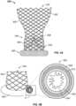
- tube 400when tube 400 is formed of a coil, the coil may take different general shapes, such as that of a circle (not illustrated), of a rectangle ( FIG. 4A ), or a diamond ( FIG. 4B ).
- the coils shown in FIG. 4A-Bare viewed along the same cutting plane P shown in FIG. 3B . As such, multiple turns or iterations of each coil shape are visible in FIGS. 4A-B . Stated more precisely, the shape of the coil is a rectangle ( FIG. 4A ) or a diamond ( FIG. 4B ) when an individual turn of the coiled wire is projected onto a plane.
- a rectangular coil 410 or diamond coil 420 for tube 400may have an advantage in that the respective coils are more readily collapsible than, for example, a circular coil or braided mesh.
- the corners 415 of rectangular coil 410 and the peaks 425 of diamond coil 420facilitate the respective coils collapsing during loading, delivery, and/or resheathing of valve 400.
- Benefits of the tube 400 being readily collapsiblemay include a reduced overall delivery profile, as well the requirement of relatively little force to load and/or resheath prosthetic valve 300 prior to being fully released in the native annulus 250. It should be noted that rectangular coil 410 is shown in FIG. 4A (and diamond coil 420 in FIG.
- tube 400does not solely refer to an elongated cylindrical structure, as the rectangular coil 410 and diamond coil 420 extended circumferentially around stent 300 is still considered herein as a tube 400.
- the tube 400need not be a toroid at all.
- tube 400 of sealing ringmay undulate such that points on the proximal (or distal) surface do not lie in the same plane as other points on the proximal (or distal) surface.
- sealing ring 350may have an undulating quality as well.
- Varying the geometry of the shape of the coilmay provide for different effects in terms of profile and sealing.
- the lengths of the major axis X MAJOR and minor axis X MINORmay be, respectively, approximately 3mm by approximately 2mm, approximately 4mm by approximately 2mm, or approximately 4mm by approximately 3mm.
- the lengths of the major and minor axesshould be understood to be examples, and not requirements. The examples given above may be useful for achieving a bulge in the sealing ring 350 of approximately 2-3mm from the outer circumference of the stent 302, which may be particularly effective at reducing PV leak.
- wires having cross-sections other than circular, including flat and/or rectangular,may be used to form coil tube 400.
- the goalis to decrease the collapsed profile of the valve 300 including sealing ring 350, while retaining enough strength within the sealing ring 350 to push or abut against the native valve annulus 250 to eliminate or reduce any gaps 200 between the native valve annulus 250 and the prosthetic valve 300.
- the thickness of the coil forming tube 400may vary in size, particularly depending upon the shape of the coil, one exemplary range of thicknesses is between approximately .05mm and approximately .175mm.
- the term thickness in the context of a coiled wirerefers to a cross-sectional dimension of the wire. For example, a coil having a circular cross-section has a thickness equal to the diameter of the cross-section. It should be noted that the above dimensions provided in relation to components of tube 400, as well as any other dimensions provided herein, are for illustrative purposes. Varying dimensions may be used without departing from the scope of this disclosure.
- the braids and/or coiled wires forming tube 400may be modified and optimized to achieve a better seal against PV leak, including, for example, the wire or braid density, shape, and stiffness.
- the ratio of thickness of the coil to the spacing between adjacent iterative shapes of the coili.e., pitch
- a relatively large pitchmay lead to kinking or tenting (i.e., a deviation from a smooth circumference) in the tube 400, which may reduce the effectiveness of sealing against PV leak.
- it may be preferable that the ratio of coil thickness to the pitchis between approximately 1:6 and approximately 1:32.
- tube 400when tube 400 is formed of a coiled material, rather than a braided mesh, it may be advantageous to include a covering 500 that at least partially surrounds tube 400. It may also be advantageous to include a filler material inside and/or outside the tube 400. However, it should be understood that a covering 500 and filler may be used regardless of whether tube 400 is formed of a coil or a braided mesh. For example, if tube 400 is formed of either a metallic coil or a metallic braided mesh, a covering 500 may be desired to reduce the likelihood and/or severity of abrasion from metal-on-metal contact between tube 400 and stent 302.
- FIGS. 5A-Fare highly schematic cross-sectional drawings of an inflow portion 330 of valve 300 with a sealing ring 350 taken along the same cutting plane P illustrated in FIG. 3B .
- sealing ring 350comprises tube 400 and covering 500.
- tube 400may take any form described above, such as a braided mesh or coil.
- covering 500 to tube 400in particular a covering 500 with low or no permeability to water and/or blood, may facilitate creating a better seal between sealing ring 350 and the native valve annulus 250.
- covering 500may accelerate clotting within sealing ring 350 to the extent clotting occurs, and may further facilitate tissue ingrowth to create a better seal over time.
- some materialsmay have greater porosity than others, and thus greater permeability to water, those materials may be advantageous if, for example, they have relatively small thickness, relatively good tissue ingrowth, or other properties that help reduce the crimp profile of sealing ring 350 with valve 300.
- Each embodiment of sealing ring 350 shown in FIGS. 5A-5Fincludes tube 400, covering 500, and one or more connections 510 connecting covering 500 to tube 400 and/or the stent 302 of valve 300.
- connections 510are described as being connected to the stent 302, connections may alternatively be connected to other portions of the prosthetic heart valve 300, such as the cuff 306, in addition or alternatively to the stent 302.
- Connectionsmay be, for example, sutures or other strand-like material.
- Various stitch patterns, such as running stitches and whip stitchesmay be used for connections 510.
- tube 400is generally described as being connected to valve 300 with stitching and/or sutures, other methods of connection, including welding, adhesives, etc. may be suitable in addition or in the alternative to stitching.
- one edge of covering 500is stitched to stent 302, tube 400 is stitched to stent 302, and covering 500 does not surround the entire cross-section of tube 400.
- one stitch 510connects a first edge of covering 500 to stent 302, another stitch 510 connects the other edge of covering 500 to tube 400, and covering 500 does not surround the entire cross-section of tube 400.
- one edge of covering 500is connected to both stent 302 and tube 400 by a single stitch 510, and the covering 500 does not surround the entire cross-section of tube 400.
- one edge of covering 500is connected to both stent 302 and tube 400 with a first stitch 510, the other edge of covering 500 is connected to tube 400 with a second stitch 510, and the covering 500 does not cover the entire cross-section of tube 400.
- covering 500surrounds the entire cross-section of tube 400, and one stitch 510 connects each edge of covering 500 to stent 302.
- covering 500surrounds the entire cross-section of tube 400 and one stitch 510 connects each edge of covering 500 to both stent 302 and tube 400.
- a number of stitches 510may be used to connect covering 500 to tube 400 and/or stent 302 along the circumference of the inflow end 330 of the stent 302. It should be noted that there may be a benefit of using few or no sutures attaching covering 500 directly to tube 400. For example, particularly when tube 400 comprises braided Nitinol, tight and/or frequent stitches 510 connecting covering 500 directly to tube 400 may reduce the ability of tube 400 to predictably undergo a transition in shape to fill gaps 200 in native valve annulus 250.
- tube 400may restrict the ability of tube 400 to change shape appropriately to fill in any gaps 200 between native valve annulus 250 and prosthetic valve 300.
- the configurations illustrated in FIGS. 5A-Dleave a proximal end of tube 400 exposed.
- tube 400is comprised of a wire coiled in a diamond shape 425, during expansion (or during collapsing), the diamond shape may grow in a lengthwise dimension as the peaks 425 of the minor axis X MINOR come together and the peaks 425 of the major axis X MAJOR move apart.
- the exposed proximal end of tube 400may facilitate such change in shape.
- the position of the covering 500 with respect to the tube 400may be reversed.
- the covering 500may be positioned to surround the proximal end of tube 400 leaving the distal end of tube 400 exposed. If the covering 500 takes this reverse position, it may be desirable to connect the covering to the valve 300 in a way to reduce the possibility of the covering 500 sliding with respect to the connection point, for example because of the force of gravity. Such connection may be made, for example, by attaching the covering 500 to an eyelet, groove, or other structure on stent 302, where the possibility of such sliding motion is limited. This reverse orientation may be applicable to remaining embodiments described below.
- covering 500need not surround the entire cross-section of tube 400, and may cover only the portion facing the direction of retrograde blood flow when implanted in an intended position. As illustrated in FIGS. 5A-F , this surface of tube 400 is oriented on the proximal end of tube 400, facing away from inflow end 330. Using a partial covering 500 may reduce the amount of material, and thus reduce the bulk and profile of valve 300 when in the collapsed condition, while covering 500 still is in contact with any retrograde blood flow contacting sealing ring 350. Covering 500 may still contact any retrograde blood flow contacting sealing ring 350 if oriented on the distal end of tube 400.
- the greater the number of stitches 510 used, both in terms of the points of connection of covering 500 to tube 400 and stent 302, as well as the frequency of those stitches along the length of the circumference of stent 302,may effect the crimp profile of valve 300.
- the crimp profile of valve 300increases and the covering 500 is more tightly attached to tube 400.
- other combinations of stitch locations and configurations of covering 500 with respect to tube 400 and stent 302may be suitable.
- FIGS. 6A-Oare highly schematic cross-sectional drawings of an inflow portion 330 of valve 300 with a sealing ring 350 taken along the same cutting plane P as shown in FIG. 3B .
- sealing ring 350comprises tube 400 and filler, with some embodiments also including covering 500.
- tube 400may take any form described above, such as a braided mesh or coil.
- Covering 500if used, may take any suitable form, such as those described above.
- the fillermay be positioned completely or substantially within tube 400 (inner filler 620), between tube 400 and covering 500 (outer filler 610, if covering 500 is present), or both.
- the fillermay help accelerate sealing against PV leak, for example by reducing clotting time, particularly if covering 500 is permeable to water. As described above in connection with FIGS. 5A-F , a variety of stitches 510 and configurations of covering 500 may be used for sealing ring 350. It should be noted that if the filler takes the form of a metal or other abrasive material, a buffer material (such as fabric) may be appropriate to include to reduce the possibility that the filler will the tube 400 will fret against one another.
- Each embodiment of sealing ring 350 shown in FIGS. 6A-6Dincludes tube 400, covering 500, outer filler 610, and one or more connections 510 connecting covering 500 and/or outer filler 610 to tube 400 and/or the stent 302 of valve 300.
- Outer filler 610refers to filler that is positioned between tube 400 and covering 500.
- covering 500surrounds the entire cross-section of tube 400 and one stitch 510 connects each edge of covering 500 to the stent 302.
- Outer filler 610is positioned between tube 400 and covering 500 and surrounds the cross-section of tube 400.
- covering 500surrounds the entire cross-section of tube 400, and one stitch 510 connects each edge of covering 500 to stent 302 and tube 400.
- Outer filler 610is positioned between tube 400 and covering 500 and surrounds the cross-section of tube 400.
- one edge of covering 500is connected to both stent 302 and tube 400 with a first stitch 510
- the other edge of covering 500is connected to tube 400 with a second stitch 510
- the covering 500does not cover the entire cross-section of tube 400.
- the outer filler 610is positioned between tune 400 and covering 500 and does not surround the entire cross-section of tube 400.
- one stitch 510connects a first edge of covering 500 to stent 302
- another stitch 510connects the other edge of covering 500 to tube 400
- covering 500does not surround the entire cross-section of tube 400.
- outer filler 610is positioned between tube 400 and covering 500 and does not surround the entire cross-section of tube 400.
- FIGS. 6E-Hcorrespond to FIGS. 6A-D , respectively, with the exception that in addition to an outer filler 610, the sealing rings 350 of FIGS. 6E-H include an inner filler 620.
- Inner filler 620refers to filler that is positioned substantially or completely within tube 400. Otherwise, the patterns of covering 500 and stitches 510 are identical between FIGS. 6A-D and 6E-H , respectively.
- FIGS. 6I-Lcorrespond to FIGS. 6E-H , respectively, with the exception that outer filler 610 is absent and only inner filler 620 is present. Otherwise, the patterns of covering 500 and stitches 510 are identical between FIGS. 6E-H and 6I-L , respectively.
- one edge of covering 500is stitched to stent 302, and covering 500 does not surround the entire cross-section of tube 400.
- Inner filler 620is positioned within tube 400. This generally corresponds to sealing ring 350 of FIG. 5A with an inner filler 620.
- one edge of covering 500is connected to both stent 302 and tube 400 by a single stitch 510, and the covering 500 does not surround the entire cross-section of tube 400.
- Inner filler 620is positioned within tube 400. This generally corresponds to sealing ring 350 of FIG. 5C with an inner filler 620.
- FIG. 6Mone edge of covering 500 is stitched to stent 302, and covering 500 does not surround the entire cross-section of tube 400.
- Inner filler 620is positioned within tube 400. This generally corresponds to sealing ring 350 of FIG. 5C with an inner filler 620.
- covering 500is absent and a single stitch 510 attaches tube 400 to stent 300, with inner filler 620 positioned within tube 400.
- inner filler 620 and tube 400be chosen such that inner filler 620 cannot escape tube 400.
- any covering 500 used in connection with fillermay surround the entire cross-section of tube 400 or only a portion thereof.
- outer filler 610may also have a similar reverse orientation.
- the tube 400may not change shapes as expected if covering 500 is tightly wrapped around and connected to tube 400. This may be particularly true of a tube 400 formed of a braided mesh.
- tacking stitching 520 or expandable stitching 530generally refers to the use of intermittent stitching along the circumference of stent 302 holding the stitched material loosely in place.
- Expandable stitching 530illustrated in FIGS. 8A-P , generally refers to stitching that allows for seam expansion. Expandable stitching 530 may be accomplished, for example, with the use of a very loose stitch or with a stitch sewn with an elastic material, such as thread formed from silicone.
- FIGS. 7A-Dillustrate sealing ring 350 with covering 500 attached at a first edge to stent 302 with a first stitch 510 and at a second edge to tube 500 with a tacking stitch 520, represented in the figures by a line with a cross through the line.
- the covering 500does not fully cover the cross-section of tube 400, nor does the outer filler 610, where present.
- FIGS. 7A-Dillustrate embodiments of sealing ring 350 with no filler ( FIG. 7A ), outer filler 610 ( FIG. 7B ), outer filler 610 and inner filler 620 ( FIG. 7C ), and inner filler 620 ( FIG. 7D ).
- FIGS. 7E-Hillustrate sealing ring 350 with covering 500 attached at a first edge to stent 302 with a stitch 510 and at a second edge to stent 302 with a tacking stitch 520.
- the covering 500fully covers the cross-section of tube 400, as does the outer filler 610, where present.
- FIGS. 7E-Hillustrate embodiments of sealing ring 350 with no filler ( FIG. 7E ), outer filler 610 ( FIG. 7F ), outer filler 610 and inner filler 620 ( FIG. 7G ), and inner filler 620 ( FIG. 7H ) .
- FIGS. 7I-Lillustrate sealing ring 350 with covering 500 attached at a first edge to stent 302 and tube 400 with a stitch 510 and at a second edge to tube 400 with a tacking stitch 520.
- the covering 500does not fully cover the cross-section of the tube 400, nor does the outer filler 610, where present.
- FIGS. 7I-Lillustrate embodiments of sealing ring 350 with no filler ( FIG. 7I ), outer filler 610 ( FIG. 7J ), outer filler 610 and inner filler 620 ( FIG. 7K ), and inner filler 620 ( FIG. 7L ).
- FIGS. 7M-Pillustrate sealing ring 350 with covering 500 attached to stent 302 and tube 400 with a stitch 500, with both edges of covering 500 attached to one another and tube 400 with a tacking stitch 520.
- the covering 500fully covers the cross-section of the tube 400, as does the outer filler 610, where present.
- FIGS. 7M-Pillustrate embodiments of sealing ring 350 with no filler ( FIG. 7M ), outer filler 610 ( FIG. 7N ), outer filler 610 and inner filler 620 ( FIG. 7O ), and inner filler 620 ( FIG. 7P ).
- FIGS. 8A-8Pillustrate embodiments of sealing ring 350 using an expandable stitch 530.
- FIGS. 8A-Dillustrate sealing ring 350 with covering 500 attached at a first edge to stent 302 with a stitch 510 and at a second edge to tube 500 with an expandable stitch 530, represented in the figures by a line with a zigzag pattern along the line. The covering 500 does not fully cover the cross-section of tube 400, nor does the outer filler 610, where present.
- FIGS. 8A-Dillustrate embodiments of sealing ring 350 with no filler ( FIG. 8A ), outer filler 610 ( FIG. 8B ), outer filler 610 and inner filler 620 ( FIG. 8C ), and inner filler 620 ( FIG. 8D ).
- FIGS. 8E-Hillustrate sealing ring 350 with covering 500 with an expandable stitch 530 attaching both edges of the covering 500 to one another and the stent 302.
- the covering 500fully covers the cross-section of tube 400, as does the outer filler 610, where present.
- FIGS. 8E-Hillustrate embodiments of sealing ring 350 with no filler ( FIG. 8E ), outer filler 610 ( FIG. 8F ), outer filler 610 and inner filler 620 ( FIG. 8G ), and inner filler 620 ( FIG. 8H ).
- FIGS. 8I-Lillustrate sealing ring 350 with covering 500 attached at a first edge to stent 302 and tube 400 with a stitch 510 and at a second edge to tube 400 with an expandable stitch 530.
- the covering 500does not fully cover the cross-section of the tube 400, nor does the outer filler 610, where present.
- FIGS. 8I-Lillustrate embodiments of sealing ring 350 with no filler ( FIG. 8I ), outer filler 610 ( FIG. 8J ), outer filler 610 and inner filler 620 ( FIG. 8K ), and inner filler 620 ( FIG. 8L ).
- FIGS. 8M-Pillustrate sealing ring 350 with covering 500 attached to stent 302 and tube 400 with a stitch 500, with both edges of covering 500 attached to one another and tube 400 with an expandable stitch 530.
- the covering 500fully covers the cross-section of the tube 400, as does the outer filler 610, where present.
- FIGS. 8M-Pillustrate embodiments of sealing ring 350 with no filler ( FIG. 8M ), outer filler 610 ( FIG. 8N ), outer filler 610 and inner filler 620 ( FIG. 8O ), and inner filler 620 ( FIG. 8P ).
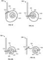
- FIGS. 9A-Eillustrate side views of prosthetic heart valve 300 being resheathed into a delivery device (heart valve 300 only labeled in FIG. 9A ).
- the delivery deviceincludes an outer sheath 700, a distal tip 710, and an inner sheath 720 (inner sheath 720 labeled only in FIG. 9A ).
- sealing ring 350takes the form of a tube 400 formed of a Nitinol coil with a diamond shape 420.
- the sealing ring 350is on the left end of the prosthetic valve 300 as illustrated.
- prosthetic heart valvemay be resheathable.
- FIGS. 7A-Eillustrate different levels of resheathing, with greater resheathing progressing from FIG. 9A to FIG. 9E .
- the rectangular shape 410 or diamond shape 420 of a coiled wire forming tube 400may allow for the tube 400 to collapse to a reduced profile during loading or resheathing the valve 300 into the delivery device. As can be seen in the illustrations, particularly from FIGS. 9B to FIG.
- the tube rectangular shape 410 or diamond shape 420 of the coiled wiremay allow the tube 400 to fold away from the remainder of valve 300 during the process.
- the sealing ring 350and in particular the tube 400, may pivot or rotate with respect to inflow end 330 of the valve 300. This is best illustrated in FIGS. 9D-E , in which the inflow end 330 enters the outer sheath 700 as the sealing ring 350 is forced to pivot or rotate away from the end of distal sheath 700.
- the entirety or nearly the entirety of inflow end 330may be positioned within outer sheath 700 prior to any of sealing ring 350 entering outer sheath 700 during a resheathing (or loading) process.
- the tube 400when fully loaded into the delivery device, the tube 400 may be completely or substantially axially offset from the remainder of prosthetic heart valve 300, including the leaflet belly B regions, reducing the crimping profile even further.
- one or more sealing ringsmay be used on a single prosthetic heart valve, including a first sealing ring disposed proximal to (or within) the native valve annulus and a second sealing ring disposed distal the first sealing ring.
- a sealing ringmay be disposed proximal to (or within) the native valve annulus, and one or more pockets expandable upon retrograde blood flow may be disposed distal the sealing ring.
- Prosthetic heart valves with expandable pocketsare described in greater detail in U.S. Patent Publication No. 2011/0098802 .
- a prosthetic heart valvecomprises: a collapsible and expandable stent extending from an inflow end to an outflow end; a plurality of prosthetic valve leaflets coupled to the stent, each leaflet having a leaflet belly; and a sealing ring coupled to the inflow end of the stent, the sealing ring comprising a tube extending circumferentially around the inflow end of the stent, the sealing ring being axially offset from the leaflet belly when the stent is in a collapsed condition, wherein the tube is formed from a wire coiled into a repeating shape such that the tube is collapsible; and/or
- a prosthetic heart valvecomprises: a collapsible and expandable stent extending from an inflow end to an outflow end; a plurality of prosthetic valve leaflets coupled to the stent, each leaflet having a leaflet belly; and a sealing ring coupled to the inflow end of the stent, the sealing ring comprising a tube extending circumferentially around the inflow end of the stent, a covering at least partially surrounding the tube, and at least one of a first filler positioned within the tube and a second filler positioned between the tube and the covering, the sealing ring being axially offset from the leaflet belly when the stent is in a collapsed condition; and/or
- a prosthetic heart valvecomprises: a collapsible and expandable stent extending from an inflow end to an outflow end; a plurality of prosthetic valve leaflets coupled to the stent, each leaflet having a leaflet belly; and a sealing ring coupled to the inflow end of the stent, the sealing ring comprising a tube extending circumferentially around the inflow end of the stent and a covering at least partially surrounding the tube, the sealing ring being axially offset from the leaflet belly when the stent is in a collapsed condition, wherein the covering has a first edge and a second edge, the first end coupled to the stent by a first thread; and/or
Landscapes
- Health & Medical Sciences (AREA)
- Cardiology (AREA)
- Engineering & Computer Science (AREA)
- Biomedical Technology (AREA)
- Heart & Thoracic Surgery (AREA)
- Transplantation (AREA)
- Oral & Maxillofacial Surgery (AREA)
- Vascular Medicine (AREA)
- Life Sciences & Earth Sciences (AREA)
- Animal Behavior & Ethology (AREA)
- General Health & Medical Sciences (AREA)
- Public Health (AREA)
- Veterinary Medicine (AREA)
- Prostheses (AREA)
Description
- The present disclosure relates to heart valve replacement and, in particular, to collapsible prosthetic heart valves. More particularly, the present disclosure relates to collapsible prosthetic transcatheter heart valves which minimize or reduce paravalvular leaks.
- Prosthetic heart valves that are collapsible to a relatively small circumferential size can be delivered into a patient less invasively than valves that are not collapsible. For example, a collapsible valve may be delivered into a patient via a tube-like delivery apparatus such as a catheter, a trocar, a laparoscopic instrument, or the like. This collapsibility can avoid the need for a more invasive procedure such as full open-chest, open-heart surgery.
- Collapsible prosthetic heart valves typically take the form of a valve structure mounted on a stent. There are two common types of stents on which the valve structures are ordinarily mounted: a self-expanding stent and a balloon-expandable stent. To place such valves into a delivery apparatus and ultimately into a patient, the valve is first collapsed or crimped to reduce its circumferential size.
- When a collapsed prosthetic valve has reached the desired implant site in the patient (e.g., at or near the annulus of the patient's heart valve that is to be replaced by the prosthetic valve), the prosthetic valve can be deployed or released from the delivery apparatus and re-expanded to full operating size. For balloon-expandable valves, this generally involves releasing the valve, assuring its proper location, and then expanding a balloon positioned within the valve stent. For self-expanding valves, on the other hand, the stent automatically expands as a sheath covering the valve is withdrawn.
- After implantation, imperfect sealing between the cuff and the site of implant may cause complications such as paravalvular leakage ("PV leak"), or blood flowing through a channel between the structure of the implanted valve and cardiac tissue as a result of the imperfect sealing.
WO 2014/121042 A1 , which was published after the declared priority date of the present application, discloses a transcatheter valve prosthesis which includes an expandable tubular stent, a prosthetic valve within the stent, and an anti-paravalvular leakage component coupled to and encircling the tubular stent.CN103705315A discloses an aortic valve stent capable of preventing perivalvular leakage. - Various aspects of the invention are set out in the appended claims. According to an example a prosthetic heart valve includes a collapsible and expandable stent extending from an inflow end to an outflow end, and a plurality of prosthetic valve leaflets coupled to the stent. Each leaflet may have a leaflet belly. The prosthetic heart valve may include a sealing ring coupled to the inflow end of the stent, the sealing ring comprising a tube extending circumferentially around the inflow end of the stent, wherein the tube is formed from a wire coiled into a repeating shape such that the tube is collapsible. The sealing ring may be axially offset from the leaflet belly when the stent is in a collapsed condition.
- According to another example, a prosthetic heart valve includes a collapsible and expandable stent extending from an inflow end to an outflow end and a plurality of prosthetic valve leaflets coupled to the stent. Each leaflet may have a leaflet belly. The prosthetic heart valve may include a sealing ring coupled to the inflow end of the stent, the sealing ring comprising a tube extending circumferentially around the inflow end of the stent, a covering at least partially surrounding the tube, and at least one of a first filler positioned within the tube and a second filler positioned between the tube and the covering. The sealing ring may be axially offset from the leaflet belly when the stent is in a collapsed condition.
- According to an example, a prosthetic heart valve includes a collapsible and expandable stent extending from an inflow end to an outflow end and a plurality of prosthetic valve leaflets coupled to the stent. Each leaflet may have a leaflet belly. The prosthetic heart valve may also include a sealing ring coupled to the inflow end of the stent, the sealing ring comprising a tube extending circumferentially around the inflow end of the stent and a covering at least partially surrounding the tube, wherein the covering has a first end and a second end, the first end coupled to the stent by a first thread. The sealing ring may be axially offset from the leaflet belly when the stent is in a collapsed condition.
- Various embodiments of the presently disclosed prosthetic heart valve may be more fully understood with reference to the following detailed description when read with the accompanying drawings, in which:
FIG. 1 is a front view of a collapsible prosthetic heart valve according to the prior art;FIG. 2 is a top cross-sectional view of the prosthetic heart valve ofFIG. 1 implanted in a patient taken along line 2-2;FIG. 3A is a highly schematic side view of one embodiment of a heart valve having a sealing ring intended to fill irregularities between the heart valve and the native valve annulus;FIG. 3B is a highly schematic cross-sectional view of the sealing ring ofFIG. 3A ;FIG. 3C is a highly schematic side view of the heart valve ofFIG. 3A implanted into a native valve annulus with unresected native valve leaflets;FIG. 3D is a highly schematic side view of the heart valve ofFIG. 3A implanted into a native valve annulus with resected native valve leaflets;FIG. 4A is a front view of a rectangular coil of a sealing ring;FIG. 4B is a front view of a diamond coil of a sealing ring;FIGS. 5A-5F are highly schematic cross sectional views of a portion of a prosthetic heart valve with a sealing ring comprising a tube and a covering;FIGS. 6A-D are highly schematic cross sectional views of a portion of a prosthetic heart valve with a sealing ring comprising a tube, a covering, and an outer filler;FIGS. 6E-H are highly schematic cross sectional views of a portion of a prosthetic heart valve with a sealing ring comprising a tube, a covering, an outer filler, and an inner filler;FIGS. 6I-N are highly schematic cross sectional views of a portion of a prosthetic heart valve with a sealing ring comprising a tube, a covering, and an inner filler;FIGS. 6O is a highly schematic cross sectional view of a portion of a prosthetic heart valve with a sealing ring comprising a tube and an inner filler;FIGS. 7A-P are highly schematic cross sectional views of a portion of a prosthetic heart valve with a sealing ring having a tacking stitch;FIGS. 8A-P are highly schematic cross sectional views of a portion of a prosthetic heart valve with a sealing ring having an expandable stitch; andFIGS. 9A-E illustrate a prosthetic heart valve at different stages of resheathing into a delivery device.- As used herein, the term "inflow end," when used in connection with a prosthetic heart valve, refers to the end of the heart valve through which blood enters when the valve is functioning as intended. The term "outflow end," when used in connection with a prosthetic heart valve, refers to the end of the heart valve through which blood exits when the valve is functioning as intended. As used herein, the terms "generally," "substantially," and "about" are intended to mean that slight deviations from absolute are included within the scope of the term so modified. Like numbers refer to similar or identical elements throughout. When used herein in the context of a prosthetic heart valve, or a component thereof, the lengthwise or axial direction refers to a direction along a longitudinal axis passing through the center of the stent or heart valve. When used herein in the context of a prosthetic heart valve, or a component thereof, the circumferential direction refers to a direction extending along the circumference of the prosthetic heart valve.
- The sealing portions of the present disclosure may be used in connection with collapsible prosthetic heart valves.
FIG. 1 shows one such collapsible stent-supportedprosthetic heart valve 100 in an expanded condition. Theprosthetic heart valve 100 is designed to replace the function of a native aortic valve of a patient. Theprosthetic heart valve 100 includes a stent constructed as aframe 102. Thestent 102 extends in a lengthwise or axial direction L from an inflow orannulus end 130 to an outflow oraortic end 132, and includes anannulus section 104 adjacent theinflow end 130 and anaortic section 142 adjacent theoutflow end 132. Theannulus section 104 has a relatively small cross section in the expanded condition, while theaortic section 142 has a relatively large cross section in the expanded condition. Theannulus section 104 may be in the form of a cylinder having a substantially constant diameter along its length. Atransition section 141 may taper outwardly from theannulus section 104 to theaortic section 142. Each of the sections of thestent 102 includes a plurality ofcells 112 connected to one another in one or more annular rows around thestent 102. For example, as shown inFIG. 1 , theannulus section 104 may have two annular rows ofcomplete cells 112 and theaortic section 142 and thetransition section 141 may each have one or more annular rows of complete orpartial cells 112. Thecells 112 in theaortic section 142 may be larger than thecells 112 in theannulus section 104. Thelarger cells 112 in theaortic section 142 may better enable theprosthetic valve 100 to be positioned without thestent structure 102 interfering with blood flow to the coronary arteries. At least partly due to the shape ofcells 112, thestent 102 elongates in the lengthwise direction L ascells 112 collapse when thestent 102 is transitioned from the expanded condition to the collapsed condition. - The
stent 102 may include one ormore retaining elements 118 at theoutflow end 132, the retainingelements 118 being sized and shaped to cooperate with retaining structures provided on a deployment device (not shown). The engagement of the retainingelements 118 with the retaining structures on the deployment device may help maintain theprosthetic heart valve 100 in assembled relationship with the deployment device, minimize longitudinal movement of the prosthetic heart valve relative to the deployment device during unsheathing or resheathing procedures, and help prevent rotation of the prosthetic heart valve relative to the deployment device as the deployment device is advanced to the target location and during deployment. One such deployment device is shown inU.S. Patent Publication No. 2012/0078352 . - The
stent 102 may also include a plurality of commissure points 116 for mounting the commissures (not identified) of the valve assembly discussed below to thestent 102. As can be seen inFIG. 1 , the commissure points 116 may lay at the intersection of fourcells 112, two of thecells 112 being adjacent one another in the same annular row, and the other twocells 112 being in different annular rows and lying in end to end relationship. The commissure points 116 may be positioned entirely within theannulus section 104 or at the juncture ofannulus section 104 and thetransition section 141. The commissure points 116 may include one or more eyelets which facilitate the suturing of the leaflet commissure to the stent. - The
prosthetic heart valve 100 includes avalve assembly 140 positioned in theannulus section 104. In the particular embodiment depicted, the valve assembly includes threeleaflets 108. Two leaflets join one another at each of three commissures. When implanted at the native aortic valve annulus, blood flows from theinflow end 130,past leaflets 108, and toward theoutflow end 132. This occurs when pressure in the left ventricle is greater than the pressure in the aorta, forcing theleaflets 108 to open. When pressure in the aorta is greater than pressure in the left ventricle, theleaflets 108 are forced closed and coapt with one another along free edges of theleaflet 108, blocking blood from flowing in a retrograde fashion from theoutflow end 132 to theinflow end 130. Thevalve assembly 140 may be mounted to thestent 102 by suturing the commissures of theleaflets 108 to the commissure points 116 and suturing other portions of thevalve assembly 140 to thestent 102, or by other methods known in the art. Thevalve assembly 140 may include acuff 106 and a plurality ofleaflets 108 which collectively function as a one way valve by coapting with one another.FIG. 1 illustrates a prosthetic heart valve for replacing a native tricuspid valve, such as the aortic valve. Accordingly, theprosthetic heart valve 100 is shown inFIG. 1 with threeleaflets 108, as well as three commissure points 116. However, it will be appreciated that the prosthetic heart valves according to aspects of the disclosure may have a greater or lesser number ofleaflets 108 and commissure points 116. - The
leaflets 108 define a leaflet belly B, indicated with broken lines inFIG. 1 . The leaflet belly B is the portions ofvalve assembly 140 above whichleaflets 108 are free to move radially inwardly to coapt with one another along their free edges. With this configuration, thevalve assembly 140 is particularly thick at points at or above leaflet belly B. As such, any additional material axially aligned withvalve assembly 140 above (or distal to) leaflet belly B may add significantly to the crimp profile of thevalve 100. - Although the
cuff 106 is shown inFIG. 1 as being disposed on the lumenal or inner surface of theannulus section 104, thecuff 106 may be disposed on the ablumenal or outer surface ofannulus section 104, or may cover all or part of either or both of the lumenal and ablumenal surfaces of theannulus section 104. As is shown inFIG. 1 , in one example the entirety of thevalve assembly 140, including the leaflet commissures, is positioned in theannulus section 104 of thestent 102. When opened, the leaflets may extend further into thetransition region 141 or may be designed such that they remain substantially completely within theannulus region 104. In this embodiment, substantially the entirety of thevalve assembly 140 is positioned between theproximal end 130 ofstent 102 and the commissure points 116, and none of the valve assembly is positioned between the commissure points 116 and thedistal end 132 of thestent 102. - In operation, the embodiments of the
prosthetic heart valve 100 described above may be used to replace a native heart valve, such as the aortic valve, a surgical heart valve, or a heart valve that has undergone a surgical procedure. Theprosthetic heart valve 100 may be delivered to the desired site (e.g., near a native aortic annulus) using any suitable delivery device. During delivery, theprosthetic heart valve 100 is disposed inside the delivery device in the collapsed condition. The delivery device may be introduced into a patient using any known procedures, such as a transfemoral, transapical, or transseptal approach. Once the delivery device has reached the target site, the user may deploy theprosthetic heart valve 100. Upon deployment, theprosthetic heart valve 100 expands into secure engagement within the native aortic annulus. When theprosthetic heart valve 100 is properly positioned inside the heart, it works as a one-way valve, allowing blood to flow in one direction and preventing blood from flowing in the opposite direction. FIG. 2 is a highly schematic cross-sectional illustration of theprosthetic heart valve 100 havingleaflets 108 disposed within thenative valve annulus 250, taken along line 2-2 shown inFIG. 1 . As seen inFIG. 2 , the substantiallycircular annulus section 104 of thestent 102 is disposed within a non-circularnative valve annulus 250. At certain locations around the perimeter of theprosthetic heart valve 100,gaps 200 form between theheart valve 100 and thenative valve annulus 250. Blood flowing through these gaps and around thevalve assembly 140 of theprosthetic heart valve 100 can result in PV leak or regurgitation and other inefficiencies which can reduce cardiac performance. Such improper fitment may be due to suboptimal native valve annulus geometry due, for example, to calcification of thenative valve annulus 250 or due to unresected native leaflets.FIG. 3A illustrates aheart valve 300 according to one embodiment of the disclosure intended to reduce the likelihood and severity of PV leak between the heart valve and a native valve annulus.Heart valve 300 may have astent 302 which extends betweeninflow end 330 andoutflow end 332, avalve assembly 340 having a plurality ofleaflets 308, and acuff 306.Heart valve 300 may be formed of any of the materials and in any of the configurations described above with reference toFIG. 1 .- The
stent 302 may be wholly or partly formed of any biocompatible material, such as metals, synthetic polymers, or biopolymers capable of functioning as a stent. Suitable biopolymers include, but are not limited to, elastin, and mixtures or composites thereof. Suitable metals include, but are not limited to, titanium, nickel, stainless steel, and alloys thereof, including nitinol. Other metals that have elastic and/or memory properties may also be suitable, such as spring stainless steel, trade named alloys such as Elgiloy®, and Hastelloy®, CoCrNi alloys (e.g., trade name Phynox), MP35N®, CoCrMo alloys, mixtures of such alloys or mixtures of metal and polymer fibers. Suitable synthetic polymers for use as a stent include, but are not limited to, thermoplastics, such as polyolefins, polyesters, polyamides, polysulfones, acrylics, polyacrylonitriles, polyetheretherketone (PEEK), and polyaramides. Furthermore, thestent 302 need not be cylindrically shaped. For example,stent 302 may take the shape of an ellipse or other shapes, such as a general "D" shape with a substantially straight section and an arcuate section extending from one end of the straight section to the other. Such a "D" shape may better conform to particular anatomies, such as the mitral valve, the tricuspid valve, or a diseased bicuspid valve. Other portions of the valve, such as the sealingring 350, described in greater detail below, may take similar shapes, for example depending on thestent 302 on which they are positioned. - The
valve assembly 340 may be wholly or partly formed of any suitable biological material or polymer. Examples of biological materials suitable for thevalve assembly 340 include, but are not limited to, porcine or bovine pericardial tissue. Examples of polymers suitable for thevalve assembly 340 include, but are not limited to, polyurethane, silicone, PTFE, and polyester. In at least some examples, portions ofvalve assembly 340, a cuff and the suture used may include an ultra-high molecular weight polyethylene. An example of onesuch valve assembly 340 is disclosed inU.S. Patent Publication No. 2010/0185277 . Althoughvalve assembly 340 typically includes one or more leaflets, other suitable valve assemblies without leaflets that work as one-way valves may be alternately used. - Similar to
cuff 106,cuff 306 may be disposed on the lumenal side ofstent 302, the ablumenal side ofstent 302, or both. Both thecuff 306 and theleaflets 308 may be wholly or partly formed of any suitable biological material or polymer, including those, such as PTFE, described above in connection with theprosthetic heart valve 300. Additionally, thecuff 306 may be formed from polyurethane copolymers or include ultra-high molecular weight polyethylene. - It should be noted that while the disclosure herein is predominately discussed in terms of a tricuspid valve, i.e., a valve having three distinct mutually coapting leaflets, and a stent having a shape as illustrated in
FIG. 3A , the valve and stent may take other forms. For example, the valve could be a bicuspid valve, i.e., a valve having two coapting leaflets, or other types of valves, including valves with greater or fewer leaflets as well as non-leaflet valves. Similarly, the stent could have different shapes, such as a flared or conical annulus section, a more or less bulbous aortic section, a differently shaped transition section between the aortic section and the annulus section, any other suitable shape, and may or may not be collapsible. Heart valve 300 may include a sealing element, such as sealingring 350, at ornear inflow end 330 ofstent 302 to help mitigate PV leak, as illustrated inFIG. 3A. FIG. 3B illustrates an enlarged cross-sectional view of sealingring 350 taken along a cutting plane P transverse to the circumferential direction of sealingring 350. Generally, sealingring 350 may comprisetube 400 with or without a covering 500, with optionalouter filler 610 between the covering 500 and thetube 400, and with optionalinner filler 620 inside thetube 400. Unless stated otherwise, the term filler, as used herein, refers to theouter filler 610 and/or theinner filler 620.Sealing ring 350 may include any combination oftube 400, covering 500, and filler. Ifouter filler 610 is used, covering 500 may be required to containouter filler 610 within sealingring 350. Prior to describing sealingring 350 in greater detail, the function of sealingring 350 is briefly explained.FIGS. 3C-D illustrateheart valve 300 disposed within anative valve annulus 250 adjacent unresectednative leaflets 203 and adjacent resected leaflets, respectively. When implanted withinnative valve annulus 250, sealingring 350 may be disposed, for example, below the native valve annulus 250 (i.e., in a sub-annular position) or below native leaflets 203 (i.e., in a sub-leaflet position). As shown inFIG. 3C , sealingring 350 is disposed such that it is in contact with the left ventricular outflow tract ("LVOT") 204, although it may be disposed within thenative annulus 250, or at the juncture betweennative annulus 250 andLVOT 204. Such positioning helps to provide a seal betweenheart valve 300 and the native heart tissue. For example, as illustrated inFIG. 3D , despitegaps 200 betweenheart valve 300 andnative valve annulus 250, sealingring 350 helps prevent retrograde blood flow around the outer circumference ofvalve 300.Sealing ring 350 may additionally help preventheart valve 300 from migrating into the aorta when implanted at the native aortic valve annulus. It should be noted that the sealingring 350 may be flexible such that it conforms to the geometry in which it is positioned. For example, sealingring 350 may conform to theLVOT 204,native annulus 250, or any other structure to a greater degree than illustrated inFIG. 3C . Also, as should be understood, sealingring 350 may be positioned below thenative annulus 250, at thenative annulus 250, above thenative annulus 250, or any combination thereof, for example being in contact with thenative annulus 250 and extending slightly below thenative annulus 250 as well.- As noted above, sealing
ring 350 may include elements such astube 400, covering 500, and filler material. Generally,tube 400 may provide a structural support onto which covering 500 may be attached and into whichouter filler 610 orinner filler 620 may be inserted.Tube 400 alone may provide sealing ofprosthetic valve 300, although such sealing may be enhanced with the addition of covering 500 and/or filler. - While the intent of sealing
ring 350 is to mitigate and/or prevent PV leak, there is generally a correlation between the amount ofmaterial forming valve 300 and the size of the valve when crimped to a collapsed condition. When using a collapsible and expandable prosthetic valve, such asvalve 300, thevalve 300 is generally crimped into a collapsed condition for loading within a sheath of a delivery device that is delivered through the body, such as through the vasculature, to the site of implantation. As such, a large crimp profile forvalve 300 generally requires the delivery device to incorporate a correspondingly large diameter sheath. As used herein, the term "crimp profile" generally refers to the largest diameter of a prosthetic valve when it is in a collapsed condition. A large diameter delivery system may be incapable of being passed through the patient's vasculature, while a delivery system having a smaller diameter and housing a heart valve with a smaller crimp profile may be easier to navigate through the patient's body and may also reduce the operation time. - As illustrated in
FIGS. 3A ,3C, and 3D , sealingring 350 may be attached to inflow end 330 ofvalve 300. In particular, sealingring 350 may be positioned such that it does not overlap in the axial direction, or only minimally overlaps, the region of the valve havingprosthetic leaflets 308 when theprosthetic heart valve 300 is in the collapsed condition. In particular, the sealingring 350 may be axially offset from the belly regions of theprosthetic leaflets 308. There may also be little or no axial overlap when theprosthetic heart valve 300 is in the expanded condition, as shown inFIGS. 3A ,3C and 3D . As used herein, "axial overlap" refers to portions of two structures being within the same radial line extending perpendicularly from the lengthwise direction L. With this configuration, whenprosthetic valve 300 is crimped into a collapsed condition, such as for loading onto a delivery device, there is little or no axial overlap between sealingring 350 and the region ofvalve 300 at whichprosthetic leaflets 308 are positioned. As a result,valve 300 may have a smaller crimp profile compared to another prosthetic valve having the same sealing ring located closer toward the region at whichprosthetic leaflets 308 are positioned. - In one example, sealing
ring 350 is positioned such that approximately half of the sealing ring is positioned above (i.e. circumferentially overlapping) thestent 302 at itsinflow end 330 and approximately half of the sealing ring is positioned below (i.e. not circumferentially overlapping) the stent at its inflow end whenvalve 300 is in the expanded condition. In another example, sealingring 350 may be nearly completely positioned below thestent 302 at itsinflow end 330 whenvalve 300 is in the expanded condition. In a further example, the proximalmost end of the sealingring 350 may substantially align with the proximal most portion of theinflow end 330 of thestent 302 whenvalve 300 is in the expanded condition. When used herein in the context of a prosthetic heart valve, the term proximal refers to a direction closer to the inflow end of the valve, while the term distal refers to a direction closer to the outflow end of the valve. - In addition to the positioning of sealing
ring 350 with respect to other components ofvalve 300, the material and structure of the components of sealingring 350 may have an effect on the effectiveness of mitigating PV leak while maintaining a relatively small crimp profile. Tube 400 of sealingring 350 may be formed of various materials. In addition, thematerial forming tube 400 may have one or more of a variety of structures. For example, the material oftube 400 may be individual strands braided into a generally tubular mesh structure, or may be an individual strand formed into a coil. For abraided tube 400, the strands forming the braid may have a particular relative orientation with respect to one another (e.g., a helical braid).- Covering 500 may be formed of one or more materials having low permeability or no permeability to water and/or blood. For example, covering 500 may be formed of tissue, including but not limited to pericardium or other sheet-like tissue obtained from animals or by tissue engineering. The covering 500 may be formed of a fabric-type material, such as a fabric formed of polytetrafluoroethylene (PTFE), polyethylene terephthalate (PET), or ultra-high molecular weight polyethylene (UHMWPE). The covering 500 may also be formed of synthetic or natural polymers, such as silicones, polyvinyl alcohol (PVA), or collagen sheets. The covering 500 may be formed of any one or any combination of the above-listed materials.
- The filler may be formed of any of a variety of materials. For example, the filler may be composed of the same material described in connection with
tube 400, such as a coil or mesh braid formed of Nitinol. The filler may also be composed of any material described in connection with covering 500, such as fabrics, tissues, and synthetic or natural polymers. Furthermore, the filler may be composed of a water swellable material, such natural sea sponge or beads, or other materials that expand upon exposure to body conditions. This may include, for example, PVA microspheres that expand upon contact with blood. Other materials that expand after exposure to temperatures found in the body or components of the blood may also be suitable for the filler. Another potential material for filler is a highly compressible sponge, for example one made from alginate cross-linked at low temperatures. Such a highly compressible sponge may collapse to a large extent when shear forces are applied, while being able to return to an original shape upon removal of the forces. Such a property may contribute to a smaller valve crimp profile while retaining the ability to "spring back" to an original shape upon deployment of the valve. Further, a single filler composed of a single material or a combination of materials described above may be used, or multiple fillers each composed of one or a combination of any of the above materials may be used. - In one embodiment,
prosthetic valve 300 may include sealingring 350 that includestube 400 formed of braided mesh of a shape-memory material, of a super-elastic material, of a bio-compatible polymer, or of another material that is capable of being collapsed and expanded into a desired shapes. Generally,tube 400 takes the shape of a hollow annulus wrapped around a portion ofstent 302, such thattube 400 generally forms a hollow torus. It should be understood thattube 400 need not meet the precise mathematical definition of a torus or other toroid.Tube 400 may comprise a braided metal fabric that is both resilient and capable of heat treatment to substantially set a desired shape, such as Nitinol, or any other metal suitable for use ofstent 302 described above. However, it should be understood that other materials, such as braided polymers, including polypropylene, may be used for the braided mesh version oftube 400. Depending on the individual material selected, the strand diameter, number of strands, and pitch may be altered to achieve the desired properties fortube 400. If sealingring 400 comprises only braided mesh, thebraided tube 400 may help in reducing PV leak, for example by creating a seal as blood clots form in the braid. PV leak may be further mitigated to the extent tissue in-growth occurs on thesealing ring 350, such as by endothelialization and/or epithelialization. Such sealing by clotting and/or thrombus formation may take up to an hour or more to form, with tissue in-growth occurring over a longer time. However, faster sealing may be a desirable result. For example, faster sealing may provide a physician with immediate or near immediate feedback that PV leak is not occurring at unacceptable levels, regardless of the fact that PV leak may be appropriately mitigated given the amount of time required for clotting in thebraided tube 400. As is described in greater detail below, a covering 500 and/or filler may be used in combination with a braided tube 400 (or acoiled tube 400 as described below) to accelerate sealing and enhance tissue in-growth. - One of the advantages of using braided Nitinol for
tube 400 is that the structure relatively easily undergoes a transition into different shapes. For example, it may be easily collapsible for delivery, easily expandable upon implantation, and may change shape as appropriate to fill ingaps 200 innative annulus 250. However, as noted above, it may be desirable to add a covering 500 and/or filler iftube 400 is formed of braided mesh. The addition of such material may change the way the braided mesh changes shapes. For example, if the braid is covered tightly with a covering 500, the braid may not behave the same as it would without such a covering. One possible solution to this challenge is the choice of material for covering 500 and/or filler material, as well as the way the covering 500 is attached totube 400, which is described in greater detail below. Another possible solution is to use a different structure fortube 400. - Instead of forming
tube 400 of a braided mesh, it may be desirable to formtube 400 from a coiled material, such as coiled Nitinol (or any other material suitable for use in forming stent 302). In particular,tube 400 may be formed of a single strand of material, or single stands of material attached end-to-end, coiled into a desired shape. For example,tube 400 may be formed of a strand of Nitinol coiled into a circular shape, a rectangular shape, or a diamond shape. The strand of material forming the coil may have various cross-sectional shapes, such as round, flat (e.g. a ribbon), or rectangular. Still further, the coiled wire may take the form of a coil, multiple wires wound together in different directions (e.g., a braid), two or more wires wound together in the same direction (e.g., two wires wound as a double helix). The coiled wire may be later cut from a tube and may have varying diameters along the length of the coil. In addition, the coil need not be a closed coil, but may be an open coil having, for example, a "U" or "C" shape. - Generally,
tube 400 may have different qualities when formed from a coil compared to a braided mesh. For example, atube 400 formed from a coil may collapse to a smaller profile than a similar tube formed of a braided mesh. On the other hand, if sealingring 350 is formed solely oftube 400 comprising a coil, sealing via clotting may be slower or may never occur at all compared to the braided mesh version. But when a covering 500 and/or filler is included with atube 400 formed of a coil, the sealingring 350 may seal against PV leak rapidly. However, it should be clear that a covering 500 and/or filler may similarly be used in conjunction with a braided mesh version oftube 400. - As noted above, when
tube 400 is formed of a coil, the coil may take different general shapes, such as that of a circle (not illustrated), of a rectangle (FIG. 4A ), or a diamond (FIG. 4B ). The coils shown inFIG. 4A-B are viewed along the same cutting plane P shown inFIG. 3B . As such, multiple turns or iterations of each coil shape are visible inFIGS. 4A-B . Stated more precisely, the shape of the coil is a rectangle (FIG. 4A ) or a diamond (FIG. 4B ) when an individual turn of the coiled wire is projected onto a plane. The use of arectangular coil 410 ordiamond coil 420 fortube 400 may have an advantage in that the respective coils are more readily collapsible than, for example, a circular coil or braided mesh. In particular, thecorners 415 ofrectangular coil 410 and thepeaks 425 ofdiamond coil 420 facilitate the respective coils collapsing during loading, delivery, and/or resheathing ofvalve 400. Benefits of thetube 400 being readily collapsible may include a reduced overall delivery profile, as well the requirement of relatively little force to load and/or resheathprosthetic valve 300 prior to being fully released in thenative annulus 250. It should be noted thatrectangular coil 410 is shown inFIG. 4A (anddiamond coil 420 inFIG. 4B ) not in the form oftube 400, but rather a segment thereof. Instent 300,rectangular coil 410 ordiamond coil 420 would extend along a circumferential path aroundinflow end 330 ofvalve 300, formingtube 400. As should be clear from the above, the term "tube" does not solely refer to an elongated cylindrical structure, as therectangular coil 410 anddiamond coil 420 extended circumferentially aroundstent 300 is still considered herein as atube 400. In fact, although shown throughout this disclosure as a torus, thetube 400 need not be a toroid at all. For example,tube 400 of sealing ring may undulate such that points on the proximal (or distal) surface do not lie in the same plane as other points on the proximal (or distal) surface. Assuch sealing ring 350 may have an undulating quality as well. - Varying the geometry of the shape of the coil may provide for different effects in terms of profile and sealing. For example, when using a
diamond coil 420, the lengths of the major axis XMAJOR and minor axis XMINOR may be, respectively, approximately 3mm by approximately 2mm, approximately 4mm by approximately 2mm, or approximately 4mm by approximately 3mm. The lengths of the major and minor axes should be understood to be examples, and not requirements. The examples given above may be useful for achieving a bulge in thesealing ring 350 of approximately 2-3mm from the outer circumference of thestent 302, which may be particularly effective at reducing PV leak. Further, as noted above, wires having cross-sections other than circular, including flat and/or rectangular, may be used to formcoil tube 400. Generally, the goal is to decrease the collapsed profile of thevalve 300 including sealingring 350, while retaining enough strength within the sealingring 350 to push or abut against thenative valve annulus 250 to eliminate or reduce anygaps 200 between thenative valve annulus 250 and theprosthetic valve 300. While the thickness of thecoil forming tube 400 may vary in size, particularly depending upon the shape of the coil, one exemplary range of thicknesses is between approximately .05mm and approximately .175mm. The term thickness in the context of a coiled wire refers to a cross-sectional dimension of the wire. For example, a coil having a circular cross-section has a thickness equal to the diameter of the cross-section. It should be noted that the above dimensions provided in relation to components oftube 400, as well as any other dimensions provided herein, are for illustrative purposes. Varying dimensions may be used without departing from the scope of this disclosure. - Other features of the braids and/or coiled
wires forming tube 400 may be modified and optimized to achieve a better seal against PV leak, including, for example, the wire or braid density, shape, and stiffness. Also, whentube 400 is formed of a coiled wire, the ratio of thickness of the coil to the spacing between adjacent iterative shapes of the coil (i.e., pitch) may have an effect on PV leak sealing. For example, a relatively large pitch may lead to kinking or tenting (i.e., a deviation from a smooth circumference) in thetube 400, which may reduce the effectiveness of sealing against PV leak. In some embodiments, it may be preferable that the ratio of coil thickness to the pitch is between approximately 1:6 and approximately 1:32. - As noted above, when
tube 400 is formed of a coiled material, rather than a braided mesh, it may be advantageous to include a covering 500 that at least partially surroundstube 400. It may also be advantageous to include a filler material inside and/or outside thetube 400. However, it should be understood that a covering 500 and filler may be used regardless of whethertube 400 is formed of a coil or a braided mesh. For example, iftube 400 is formed of either a metallic coil or a metallic braided mesh, a covering 500 may be desired to reduce the likelihood and/or severity of abrasion from metal-on-metal contact betweentube 400 andstent 302. FIGS. 5A-F are highly schematic cross-sectional drawings of aninflow portion 330 ofvalve 300 with asealing ring 350 taken along the same cutting plane P illustrated inFIG. 3B . In these embodiments, sealingring 350 comprisestube 400 and covering 500. In particular,tube 400 may take any form described above, such as a braided mesh or coil. The addition of covering 500 totube 400, in particular a covering 500 with low or no permeability to water and/or blood, may facilitate creating a better seal between sealingring 350 and thenative valve annulus 250. In addition to physically blocking blood from flowing past the sealingring 350, covering 500 may accelerate clotting within sealingring 350 to the extent clotting occurs, and may further facilitate tissue ingrowth to create a better seal over time. Although some materials may have greater porosity than others, and thus greater permeability to water, those materials may be advantageous if, for example, they have relatively small thickness, relatively good tissue ingrowth, or other properties that help reduce the crimp profile of sealingring 350 withvalve 300.- Each embodiment of sealing
ring 350 shown inFIGS. 5A-5F includestube 400, covering 500, and one ormore connections 510 connecting covering 500 totube 400 and/or thestent 302 ofvalve 300. It should be noted that althoughconnections 510 are described as being connected to thestent 302, connections may alternatively be connected to other portions of theprosthetic heart valve 300, such as thecuff 306, in addition or alternatively to thestent 302. Connections may be, for example, sutures or other strand-like material. Various stitch patterns, such as running stitches and whip stitches, may be used forconnections 510. It should further be noted that, althoughtube 400 is generally described as being connected tovalve 300 with stitching and/or sutures, other methods of connection, including welding, adhesives, etc. may be suitable in addition or in the alternative to stitching. - In
FIG. 5A , one edge of covering 500 is stitched tostent 302,tube 400 is stitched tostent 302, and covering 500 does not surround the entire cross-section oftube 400. InFIG. 5B , onestitch 510 connects a first edge of covering 500 tostent 302, anotherstitch 510 connects the other edge of covering 500 totube 400, and covering 500 does not surround the entire cross-section oftube 400. InFIG. 5C , one edge of covering 500 is connected to bothstent 302 andtube 400 by asingle stitch 510, and the covering 500 does not surround the entire cross-section oftube 400. InFIG. 5D , one edge of covering 500 is connected to bothstent 302 andtube 400 with afirst stitch 510, the other edge of covering 500 is connected totube 400 with asecond stitch 510, and the covering 500 does not cover the entire cross-section oftube 400. InFIG. 5E , covering 500 surrounds the entire cross-section oftube 400, and onestitch 510 connects each edge of covering 500 tostent 302. InFIG. 5F , covering 500 surrounds the entire cross-section oftube 400 and onestitch 510 connects each edge of covering 500 to bothstent 302 andtube 400. - In each of the embodiments described in connection with
FIGS. 5A-F , a number ofstitches 510 may be used to connect covering 500 totube 400 and/orstent 302 along the circumference of theinflow end 330 of thestent 302. It should be noted that there may be a benefit of using few or no sutures attaching covering 500 directly totube 400. For example, particularly whentube 400 comprises braided Nitinol, tight and/orfrequent stitches 510 connecting covering 500 directly totube 400 may reduce the ability oftube 400 to predictably undergo a transition in shape to fillgaps 200 innative valve annulus 250. Additionally, allowing little or no slack betweentube 400 and covering 500 may restrict the ability oftube 400 to change shape appropriately to fill in anygaps 200 betweennative valve annulus 250 andprosthetic valve 300. For example, the configurations illustrated inFIGS. 5A-D leave a proximal end oftube 400 exposed. Iftube 400 is comprised of a wire coiled in adiamond shape 425, during expansion (or during collapsing), the diamond shape may grow in a lengthwise dimension as thepeaks 425 of the minor axis XMINOR come together and thepeaks 425 of the major axis XMAJOR move apart. The exposed proximal end oftube 400 may facilitate such change in shape. It should further be noted that, particularly in embodiments in which both edges of covering 500 are connected to thestent 302 and/ortube 400, the position of the covering 500 with respect to thetube 400 may be reversed. Taking the embodiment illustrated inFIG. 5D as an example, the covering 500 may be positioned to surround the proximal end oftube 400 leaving the distal end oftube 400 exposed. If the covering 500 takes this reverse position, it may be desirable to connect the covering to thevalve 300 in a way to reduce the possibility of the covering 500 sliding with respect to the connection point, for example because of the force of gravity. Such connection may be made, for example, by attaching the covering 500 to an eyelet, groove, or other structure onstent 302, where the possibility of such sliding motion is limited. This reverse orientation may be applicable to remaining embodiments described below. - As should be clear from the above description, covering 500 need not surround the entire cross-section of
tube 400, and may cover only the portion facing the direction of retrograde blood flow when implanted in an intended position. As illustrated inFIGS. 5A-F , this surface oftube 400 is oriented on the proximal end oftube 400, facing away frominflow end 330. Using apartial covering 500 may reduce the amount of material, and thus reduce the bulk and profile ofvalve 300 when in the collapsed condition, while covering 500 still is in contact with any retrograde blood flow contactingsealing ring 350. Covering 500 may still contact any retrograde blood flow contactingsealing ring 350 if oriented on the distal end oftube 400. Similarly, the greater the number ofstitches 510 used, both in terms of the points of connection of covering 500 totube 400 andstent 302, as well as the frequency of those stitches along the length of the circumference ofstent 302, may effect the crimp profile ofvalve 300. Generally, asmore stitches 510 are used, the crimp profile ofvalve 300 increases and the covering 500 is more tightly attached totube 400. Although not described above, other combinations of stitch locations and configurations of covering 500 with respect totube 400 andstent 302 may be suitable. FIGS. 6A-O are highly schematic cross-sectional drawings of aninflow portion 330 ofvalve 300 with asealing ring 350 taken along the same cutting plane P as shown inFIG. 3B . In these embodiments, sealingring 350 comprisestube 400 and filler, with some embodiments also including covering 500. In particular,tube 400 may take any form described above, such as a braided mesh or coil. Covering 500, if used, may take any suitable form, such as those described above. The filler may be positioned completely or substantially within tube 400 (inner filler 620), betweentube 400 and covering 500 (outer filler 610, if covering 500 is present), or both. The filler may help accelerate sealing against PV leak, for example by reducing clotting time, particularly if covering 500 is permeable to water. As described above in connection withFIGS. 5A-F , a variety ofstitches 510 and configurations of covering 500 may be used for sealingring 350. It should be noted that if the filler takes the form of a metal or other abrasive material, a buffer material (such as fabric) may be appropriate to include to reduce the possibility that the filler will thetube 400 will fret against one another.- Each embodiment of sealing
ring 350 shown inFIGS. 6A-6D includestube 400, covering 500,outer filler 610, and one ormore connections 510 connecting covering 500 and/orouter filler 610 totube 400 and/or thestent 302 ofvalve 300.Outer filler 610 refers to filler that is positioned betweentube 400 and covering 500. InFIG. 6A , covering 500 surrounds the entire cross-section oftube 400 and onestitch 510 connects each edge of covering 500 to thestent 302.Outer filler 610 is positioned betweentube 400 and covering 500 and surrounds the cross-section oftube 400. InFIG. 6B , covering 500 surrounds the entire cross-section oftube 400, and onestitch 510 connects each edge of covering 500 tostent 302 andtube 400.Outer filler 610 is positioned betweentube 400 and covering 500 and surrounds the cross-section oftube 400. InFIG. 6C , one edge of covering 500 is connected to bothstent 302 andtube 400 with afirst stitch 510, the other edge of covering 500 is connected totube 400 with asecond stitch 510, and the covering 500 does not cover the entire cross-section oftube 400. Similarly, theouter filler 610 is positioned betweentune 400 and covering 500 and does not surround the entire cross-section oftube 400. InFIG. 6D , onestitch 510 connects a first edge of covering 500 tostent 302, anotherstitch 510 connects the other edge of covering 500 totube 400, and covering 500 does not surround the entire cross-section oftube 400. Similarly,outer filler 610 is positioned betweentube 400 and covering 500 and does not surround the entire cross-section oftube 400. FIGS. 6E-H correspond toFIGS. 6A-D , respectively, with the exception that in addition to anouter filler 610, the sealing rings 350 ofFIGS. 6E-H include aninner filler 620.Inner filler 620 refers to filler that is positioned substantially or completely withintube 400. Otherwise, the patterns of covering 500 and stitches 510 are identical betweenFIGS. 6A-D and6E-H , respectively.FIGS. 6I-L correspond toFIGS. 6E-H , respectively, with the exception thatouter filler 610 is absent and onlyinner filler 620 is present. Otherwise, the patterns of covering 500 and stitches 510 are identical betweenFIGS. 6E-H and6I-L , respectively.- In
FIG. 6M , one edge of covering 500 is stitched tostent 302, and covering 500 does not surround the entire cross-section oftube 400.Inner filler 620 is positioned withintube 400. This generally corresponds to sealingring 350 ofFIG. 5A with aninner filler 620. InFIG. 6N , one edge of covering 500 is connected to bothstent 302 andtube 400 by asingle stitch 510, and the covering 500 does not surround the entire cross-section oftube 400.Inner filler 620 is positioned withintube 400. This generally corresponds to sealingring 350 ofFIG. 5C with aninner filler 620. InFIG. 6O , covering 500 is absent and asingle stitch 510 attachestube 400 tostent 300, withinner filler 620 positioned withintube 400. In this embodiment, it is important thatinner filler 620 andtube 400 be chosen such thatinner filler 620 cannot escapetube 400. - As described in connection with sealing
rings 350 illustrated inFIGS. 5A-F , any covering 500 used in connection with filler may surround the entire cross-section oftube 400 or only a portion thereof. The same is true ofouter filler 610. Further, as described above with reference toFIGS. 5A-F , the orientation of covering 500 may be reversed so that the covering 500 covers only a distal portion oftube 400. In embodiments in which covering 500 has this reverse orientation,outer filler 610 may also have a similar reverse orientation. - As described above the
tube 400 may not change shapes as expected if covering 500 is tightly wrapped around and connected totube 400. This may be particularly true of atube 400 formed of a braided mesh. One way of mitigating this potential problem is, as described above, reducing or eliminating the number ofstitches 500 directly connecting covering 500 totube 400. However, another solution is the use of tackingstitching 520 orexpandable stitching 530. Tackingstitching 520, illustrated inFIGS. 7A-P , generally refers to the use of intermittent stitching along the circumference ofstent 302 holding the stitched material loosely in place.Expandable stitching 530, illustrated inFIGS. 8A-P , generally refers to stitching that allows for seam expansion.Expandable stitching 530 may be accomplished, for example, with the use of a very loose stitch or with a stitch sewn with an elastic material, such as thread formed from silicone. - For example,
FIGS. 7A-D illustrate sealingring 350 with covering 500 attached at a first edge tostent 302 with afirst stitch 510 and at a second edge totube 500 with a tackingstitch 520, represented in the figures by a line with a cross through the line. The covering 500 does not fully cover the cross-section oftube 400, nor does theouter filler 610, where present.FIGS. 7A-D illustrate embodiments of sealingring 350 with no filler (FIG. 7A ), outer filler 610 (FIG. 7B ),outer filler 610 and inner filler 620 (FIG. 7C ), and inner filler 620 (FIG. 7D ). FIGS. 7E-H illustrate sealingring 350 with covering 500 attached at a first edge tostent 302 with astitch 510 and at a second edge tostent 302 with a tackingstitch 520. The covering 500 fully covers the cross-section oftube 400, as does theouter filler 610, where present.FIGS. 7E-H illustrate embodiments of sealingring 350 with no filler (FIG. 7E ), outer filler 610 (FIG. 7F ),outer filler 610 and inner filler 620 (FIG. 7G ), and inner filler 620 (FIG. 7H ) .FIGS. 7I-L illustrate sealingring 350 with covering 500 attached at a first edge tostent 302 andtube 400 with astitch 510 and at a second edge totube 400 with a tackingstitch 520. The covering 500 does not fully cover the cross-section of thetube 400, nor does theouter filler 610, where present.FIGS. 7I-L illustrate embodiments of sealingring 350 with no filler (FIG. 7I ), outer filler 610 (FIG. 7J ),outer filler 610 and inner filler 620 (FIG. 7K ), and inner filler 620 (FIG. 7L ).FIGS. 7M-P illustrate sealingring 350 with covering 500 attached tostent 302 andtube 400 with astitch 500, with both edges of covering 500 attached to one another andtube 400 with a tackingstitch 520. The covering 500 fully covers the cross-section of thetube 400, as does theouter filler 610, where present.FIGS. 7M-P illustrate embodiments of sealingring 350 with no filler (FIG. 7M ), outer filler 610 (FIG. 7N ),outer filler 610 and inner filler 620 (FIG. 7O ), and inner filler 620 (FIG. 7P ).FIGS. 8A-8P illustrate embodiments of sealingring 350 using anexpandable stitch 530.FIGS. 8A-D illustrate sealingring 350 with covering 500 attached at a first edge tostent 302 with astitch 510 and at a second edge totube 500 with anexpandable stitch 530, represented in the figures by a line with a zigzag pattern along the line. The covering 500 does not fully cover the cross-section oftube 400, nor does theouter filler 610, where present.FIGS. 8A-D illustrate embodiments of sealingring 350 with no filler (FIG. 8A ), outer filler 610 (FIG. 8B ),outer filler 610 and inner filler 620 (FIG. 8C ), and inner filler 620 (FIG. 8D ).FIGS. 8E-H illustrate sealingring 350 with covering 500 with anexpandable stitch 530 attaching both edges of the covering 500 to one another and thestent 302. The covering 500 fully covers the cross-section oftube 400, as does theouter filler 610, where present.FIGS. 8E-H illustrate embodiments of sealingring 350 with no filler (FIG. 8E ), outer filler 610 (FIG. 8F ),outer filler 610 and inner filler 620 (FIG. 8G ), and inner filler 620 (FIG. 8H ).FIGS. 8I-L illustrate sealingring 350 with covering 500 attached at a first edge tostent 302 andtube 400 with astitch 510 and at a second edge totube 400 with anexpandable stitch 530. The covering 500 does not fully cover the cross-section of thetube 400, nor does theouter filler 610, where present.FIGS. 8I-L illustrate embodiments of sealingring 350 with no filler (FIG. 8I ), outer filler 610 (FIG. 8J ),outer filler 610 and inner filler 620 (FIG. 8K ), and inner filler 620 (FIG. 8L ).FIGS. 8M-P illustrate sealingring 350 with covering 500 attached tostent 302 andtube 400 with astitch 500, with both edges of covering 500 attached to one another andtube 400 with anexpandable stitch 530. The covering 500 fully covers the cross-section of thetube 400, as does theouter filler 610, where present.FIGS. 8M-P illustrate embodiments of sealingring 350 with no filler (FIG. 8M ), outer filler 610 (FIG. 8N ),outer filler 610 and inner filler 620 (FIG. 8O ), and inner filler 620 (FIG. 8P ).FIGS. 9A-E illustrate side views ofprosthetic heart valve 300 being resheathed into a delivery device (heart valve 300 only labeled inFIG. 9A ). Briefly, the delivery device includes anouter sheath 700, adistal tip 710, and an inner sheath 720 (inner sheath 720 labeled only inFIG. 9A ). In this embodiment, sealingring 350 takes the form of atube 400 formed of a Nitinol coil with adiamond shape 420. The sealingring 350 is on the left end of theprosthetic valve 300 as illustrated. As noted above, prosthetic heart valve may be resheathable. For example, during delivery, a user may first allowprosthetic heart valve 300 to partially expand outside ofouter sheath 700 to test positioning and functioning of the valve (FIG. 9A ) prior to fully releasing the valve.FIGS. 7A-E illustrate different levels of resheathing, with greater resheathing progressing fromFIG. 9A to FIG. 9E . As described above with respect toFIGS. 4A-B , therectangular shape 410 ordiamond shape 420 of a coiledwire forming tube 400 may allow for thetube 400 to collapse to a reduced profile during loading or resheathing thevalve 300 into the delivery device. As can be seen in the illustrations, particularly fromFIGS. 9B to FIG. 9D , during loading or resheathing, the tuberectangular shape 410 ordiamond shape 420 of the coiled wire may allow thetube 400 to fold away from the remainder ofvalve 300 during the process. In addition to collapsing during resheathing (or loading), the sealingring 350, and in particular thetube 400, may pivot or rotate with respect to inflow end 330 of thevalve 300. This is best illustrated inFIGS. 9D-E , in which theinflow end 330 enters theouter sheath 700 as the sealingring 350 is forced to pivot or rotate away from the end ofdistal sheath 700. For example, the entirety or nearly the entirety ofinflow end 330 may be positioned withinouter sheath 700 prior to any of sealingring 350 enteringouter sheath 700 during a resheathing (or loading) process. As such, when fully loaded into the delivery device, thetube 400 may be completely or substantially axially offset from the remainder ofprosthetic heart valve 300, including the leaflet belly B regions, reducing the crimping profile even further.- Although certain embodiments of the prosthetic heart valve described herein may provide a single feature for reducing paravalvular leakage, it should be understood that multiple similar or dissimilar features may be utilized on a single prosthetic heart valve to reduce paravalvular leak. For example, one or more sealing rings may be used on a single prosthetic heart valve, including a first sealing ring disposed proximal to (or within) the native valve annulus and a second sealing ring disposed distal the first sealing ring. In other examples, a sealing ring may be disposed proximal to (or within) the native valve annulus, and one or more pockets expandable upon retrograde blood flow may be disposed distal the sealing ring. Prosthetic heart valves with expandable pockets are described in greater detail in
U.S. Patent Publication No. 2011/0098802 . - In one embodiment of the disclosure, a prosthetic heart valve comprises: a collapsible and expandable stent extending from an inflow end to an outflow end; a plurality of prosthetic valve leaflets coupled to the stent, each leaflet having a leaflet belly; and a sealing ring coupled to the inflow end of the stent, the sealing ring comprising a tube extending circumferentially around the inflow end of the stent, the sealing ring being axially offset from the leaflet belly when the stent is in a collapsed condition, wherein the tube is formed from a wire coiled into a repeating shape such that the tube is collapsible; and/or
- the wire is coiled into a rectangular shape; and/or
- the wire is coiled into a diamond shape having a major axis and a minor axis; and/or
- the major axis is approximately 3mm and the minor axis is approximately 2mm; and/or
- the major axis is approximately 4mm and the minor axis is approximately 2mm; and/or
- the major axis is approximately 4mm and the minor axis is approximately 3mm; and/or
- the wire has a thickness of between approximately .05mm and approximately .175mm; and/or
- the wire has a thickness and there is a distance between adjacent repeating shapes of the coiled wire, a ratio of the thickness to the distance being between approximately 1:6 and approximately 1:32.
- In another embodiment of the disclosure, a prosthetic heart valve comprises: a collapsible and expandable stent extending from an inflow end to an outflow end; a plurality of prosthetic valve leaflets coupled to the stent, each leaflet having a leaflet belly; and a sealing ring coupled to the inflow end of the stent, the sealing ring comprising a tube extending circumferentially around the inflow end of the stent, a covering at least partially surrounding the tube, and at least one of a first filler positioned within the tube and a second filler positioned between the tube and the covering, the sealing ring being axially offset from the leaflet belly when the stent is in a collapsed condition; and/or
- the covering is formed from a material selected form the group consisting of tissues, fabrics, and polymers; and/or
- at least one of the first filler and the second filler is formed from a material selected from the group consisting of metals, tissues, fabrics, polymers, and water-swellable materials; and/or
- at least one of the first filler and the second filler is configured to expand upon exposure to blood.
- In a further embodiment of the disclosure, a prosthetic heart valve comprises: a collapsible and expandable stent extending from an inflow end to an outflow end; a plurality of prosthetic valve leaflets coupled to the stent, each leaflet having a leaflet belly; and a sealing ring coupled to the inflow end of the stent, the sealing ring comprising a tube extending circumferentially around the inflow end of the stent and a covering at least partially surrounding the tube, the sealing ring being axially offset from the leaflet belly when the stent is in a collapsed condition, wherein the covering has a first edge and a second edge, the first end coupled to the stent by a first thread; and/or
- the first thread couples the first edge of the covering and the tube to the stent; and/or
- a second thread coupling the second edge of the covering to the tube; and/or
- the second thread is formed of an elastic material; and/or
- the first thread couples the second edge of the covering to the first edge of the covering and the stent; and/or
- the first thread is formed of an elastic material; and/or
- the elastic material is silicone.
- Although the invention herein has been described with reference to particular embodiments, it is to be understood that these embodiments are merely illustrative of the principles and applications of the present invention. The invention is disclosed by the appended claims.
Claims (17)
- A prosthetic heart valve (300) comprising:a collapsible and expandable stent (302) extending from an inflow end (330) to an outflow end (332);a plurality of prosthetic valve leaflets (308) coupled to the stent (302), each leaflet (308) having a leaflet belly, the leaflet bellies being portions of the prosthetic valve leaflets above which the prosthetic valve leaflets are free to move radially inwardly to coapt with one another; anda sealing ring (350) coupled to stent (302) adjacent the inflow end (330) of the stent (302),the prosthetic heart valvecharacterized in that the sealing ring (350) comprises a tube (400) extending circumferentially around the inflow end (330) of the stent (302), the sealing ring (350) is axially offset from the leaflet belly when the stent (302) is in a collapsed condition so that there is no axial overlap between the leaflet belly and the sealing ring, and the tube (400) includes a wire coiled into a repeating shape such that the tube (400) is collapsible, the repeating shape being a diamond shape having a major axis (XMAJOR) and a minor axis (XMINOR).
- The prosthetic heart valve (300) of claim 1, wherein the major axis (XMAJOR) is approximately 3mm and the minor axis (XMINOR) is approximately 2mm.
- The prosthetic heart valve (300) of claim 1, wherein the major axis (XMAJOR) is approximately 4mm and the minor axis (XMINOR) is approximately 2mm.
- The prosthetic heart valve (300) of claim 1, wherein the major axis (XMAJOR) is approximately 4mm and the minor axis (XMINOR) is approximately 3mm.
- The prosthetic heart valve (300) of claim 1, wherein the wire has a thickness of between approximately .05mm and approximately .175mm.
- The prosthetic heart valve (300) of claim 1, wherein the wire has a thickness and there is a distance between adjacent repeating shapes of the coiled wire, a ratio of the thickness to the distance being between approximately 1:6 and approximately 1:32.
- The prosthetic heart valve of claim 1, further comprising:
a covering (500) at least partially surrounding the tube (400), and at least one of a first filler (620) positioned within the tube (400) and a second filler (610) positioned between the tube (400) and the covering (500). - The prosthetic heart valve (300) of claim 7, wherein the covering (500) is formed from a material selected form the group consisting of tissues, fabrics, and polymers.
- The prosthetic heart valve (300) of claim 7, wherein at least one of the first filler (620) and the second filler (610) is formed from a material selected from the group consisting of metals, tissues, fabrics, polymers, and water-swellable materials.
- The prosthetic heart valve (300) of claim 7, wherein at least one of the first filler (620) and the second filler (610) is configured to expand upon exposure to blood.
- The prosthetic heart valve (300) of claim 7,
wherein the covering (500) has a first edge and a second edge, the first edge coupled to the stent (302) by a first thread (510). - The prosthetic heart valve (300) of claim 11, wherein the first thread (510) couples the first edge of the covering (500) and the tube (400) to the stent (302).
- The prosthetic heart valve (300) of claim 11, further comprising a second thread (510) coupling the second edge of the covering (500) to the tube (400).
- The prosthetic heart valve (300) of claim 13, wherein the second thread (510) is formed of an elastic material.
- The prosthetic heart valve (300) of claim 11, wherein the first thread (510) couples the second edge of the covering to the first edge of the covering (500) and the stent (302).
- The prosthetic heart valve (300) of claim 15, wherein the first thread (510) is formed of an elastic material.
- The prosthetic heart valve (300) of claim 16, wherein the elastic material is silicone.
Applications Claiming Priority (2)
| Application Number | Priority Date | Filing Date | Title |
|---|---|---|---|
| US201461994253P | 2014-05-16 | 2014-05-16 | |
| PCT/US2015/030250WO2015175450A1 (en) | 2014-05-16 | 2015-05-12 | Transcatheter valve with paravalvular leak sealing ring |
Publications (2)
| Publication Number | Publication Date |
|---|---|
| EP3142604A1 EP3142604A1 (en) | 2017-03-22 |
| EP3142604B1true EP3142604B1 (en) | 2024-01-10 |
Family
ID=53268894
Family Applications (1)
| Application Number | Title | Priority Date | Filing Date |
|---|---|---|---|
| EP15725169.5AActiveEP3142604B1 (en) | 2014-05-16 | 2015-05-12 | Transcatheter valve with paravalvular leak sealing ring |
Country Status (3)
| Country | Link |
|---|---|
| US (3) | US9668858B2 (en) |
| EP (1) | EP3142604B1 (en) |
| WO (1) | WO2015175450A1 (en) |
Families Citing this family (100)
| Publication number | Priority date | Publication date | Assignee | Title |
|---|---|---|---|---|
| DE102007043830A1 (en) | 2007-09-13 | 2009-04-02 | Lozonschi, Lucian, Madison | Heart valve stent |
| EP3443938B1 (en)* | 2007-09-26 | 2024-01-24 | St. Jude Medical, LLC | Collapsible prosthetic heart valves |
| US9532868B2 (en) | 2007-09-28 | 2017-01-03 | St. Jude Medical, Inc. | Collapsible-expandable prosthetic heart valves with structures for clamping native tissue |
| EP3300695B1 (en) | 2009-12-08 | 2023-05-24 | Avalon Medical Ltd. | Device and system for transcatheter mitral valve replacement |
| EP4289398A3 (en) | 2011-08-11 | 2024-03-13 | Tendyne Holdings, Inc. | Improvements for prosthetic valves and related inventions |
| US9827092B2 (en) | 2011-12-16 | 2017-11-28 | Tendyne Holdings, Inc. | Tethers for prosthetic mitral valve |
| US9427315B2 (en) | 2012-04-19 | 2016-08-30 | Caisson Interventional, LLC | Valve replacement systems and methods |
| US9011515B2 (en) | 2012-04-19 | 2015-04-21 | Caisson Interventional, LLC | Heart valve assembly systems and methods |
| WO2014022124A1 (en) | 2012-07-28 | 2014-02-06 | Tendyne Holdings, Inc. | Improved multi-component designs for heart valve retrieval device, sealing structures and stent assembly |
| WO2014021905A1 (en) | 2012-07-30 | 2014-02-06 | Tendyne Holdings, Inc. | Improved delivery systems and methods for transcatheter prosthetic valves |
| US9675451B2 (en) | 2013-02-01 | 2017-06-13 | Medtronic CV Luxembourg S.a.r.l. | Anti-paravalvular leakage component for a transcatheter valve prosthesis |
| US8986375B2 (en)* | 2013-03-12 | 2015-03-24 | Medtronic, Inc. | Anti-paravalvular leakage component for a transcatheter valve prosthesis |
| US11224510B2 (en) | 2013-04-02 | 2022-01-18 | Tendyne Holdings, Inc. | Prosthetic heart valve and systems and methods for delivering the same |
| US10463489B2 (en) | 2013-04-02 | 2019-11-05 | Tendyne Holdings, Inc. | Prosthetic heart valve and systems and methods for delivering the same |
| US10478293B2 (en) | 2013-04-04 | 2019-11-19 | Tendyne Holdings, Inc. | Retrieval and repositioning system for prosthetic heart valve |
| US9610159B2 (en) | 2013-05-30 | 2017-04-04 | Tendyne Holdings, Inc. | Structural members for prosthetic mitral valves |
| CN105658178B (en) | 2013-06-25 | 2018-05-08 | 坦迪尼控股股份有限公司 | Thrombus management and structural compliance features for prosthetic heart valves |
| AU2014296087B2 (en) | 2013-08-01 | 2019-08-01 | Tendyne Holdings, Inc. | Epicardial anchor devices and methods |
| WO2015058039A1 (en) | 2013-10-17 | 2015-04-23 | Robert Vidlund | Apparatus and methods for alignment and deployment of intracardiac devices |
| US9050188B2 (en) | 2013-10-23 | 2015-06-09 | Caisson Interventional, LLC | Methods and systems for heart valve therapy |
| EP3062744B1 (en) | 2013-10-28 | 2020-01-22 | Tendyne Holdings, Inc. | Prosthetic heart valve and systems for delivering the same |
| US9526611B2 (en) | 2013-10-29 | 2016-12-27 | Tendyne Holdings, Inc. | Apparatus and methods for delivery of transcatheter prosthetic valves |
| WO2015120122A2 (en) | 2014-02-05 | 2015-08-13 | Robert Vidlund | Apparatus and methods for transfemoral delivery of prosthetic mitral valve |
| US9986993B2 (en) | 2014-02-11 | 2018-06-05 | Tendyne Holdings, Inc. | Adjustable tether and epicardial pad system for prosthetic heart valve |
| WO2015126711A1 (en)* | 2014-02-18 | 2015-08-27 | St. Jude Medical, Cardiology Division, Inc. | Bowed runners and corresponding valve assemblies for paravalvular leak protection |
| JP6865037B2 (en) | 2014-03-10 | 2021-04-28 | テンダイン ホールディングス,インコーポレイテッド | Devices and methods for positioning the artificial mitral valve and monitoring the tether load of the artificial mitral valve |
| EP3142604B1 (en)* | 2014-05-16 | 2024-01-10 | St. Jude Medical, Cardiology Division, Inc. | Transcatheter valve with paravalvular leak sealing ring |
| US9974647B2 (en) | 2014-06-12 | 2018-05-22 | Caisson Interventional, LLC | Two stage anchor and mitral valve assembly |
| US9750607B2 (en) | 2014-10-23 | 2017-09-05 | Caisson Interventional, LLC | Systems and methods for heart valve therapy |
| US9750605B2 (en) | 2014-10-23 | 2017-09-05 | Caisson Interventional, LLC | Systems and methods for heart valve therapy |
| AU2016205371B2 (en) | 2015-01-07 | 2019-10-10 | Tendyne Holdings, Inc. | Prosthetic mitral valves and apparatus and methods for delivery of same |
| AU2016215197B2 (en) | 2015-02-05 | 2020-01-02 | Tendyne Holdings Inc. | Expandable epicardial pads and devices and methods for their delivery |
| US10080652B2 (en)* | 2015-03-13 | 2018-09-25 | Boston Scientific Scimed, Inc. | Prosthetic heart valve having an improved tubular seal |
| EP3270827B1 (en) | 2015-03-19 | 2023-12-20 | Caisson Interventional, LLC | Systems for heart valve therapy |
| CA2983002C (en) | 2015-04-16 | 2023-07-04 | Tendyne Holdings, Inc. | Apparatus and methods for delivery, repositioning, and retrieval of transcatheter prosthetic valves |
| US10080653B2 (en)* | 2015-09-10 | 2018-09-25 | Edwards Lifesciences Corporation | Limited expansion heart valve |
| US10327894B2 (en) | 2015-09-18 | 2019-06-25 | Tendyne Holdings, Inc. | Methods for delivery of prosthetic mitral valves |
| AU2016362474B2 (en) | 2015-12-03 | 2021-04-22 | Tendyne Holdings, Inc. | Frame features for prosthetic mitral valves |
| WO2017117109A1 (en)* | 2015-12-28 | 2017-07-06 | Tendyne Holdings, Inc. | Atrial pocket closures for prosthetic heart valves |
| WO2017117388A1 (en) | 2015-12-30 | 2017-07-06 | Caisson Interventional, LLC | Systems and methods for heart valve therapy |
| DE102016103843A1 (en)* | 2016-03-03 | 2017-09-07 | Biotronik Ag | Reduction of paravalvular leakage through controlled thrombus buildup |
| CN108834399B (en)* | 2016-03-14 | 2024-06-11 | 美敦力瓦斯科尔勒公司 | Stented prosthetic heart valve with wrap and delivery device |
| US10470877B2 (en) | 2016-05-03 | 2019-11-12 | Tendyne Holdings, Inc. | Apparatus and methods for anterior valve leaflet management |
| US11039921B2 (en) | 2016-06-13 | 2021-06-22 | Tendyne Holdings, Inc. | Sequential delivery of two-part prosthetic mitral valve |
| JP6968113B2 (en) | 2016-06-30 | 2021-11-17 | テンダイン ホールディングス,インコーポレイテッド | Transapical delivery device for artificial heart valves |
| WO2018013515A1 (en) | 2016-07-12 | 2018-01-18 | Tendyne Holdings, Inc. | Apparatus and methods for trans-septal retrieval of prosthetic heart valves |
| US10653523B2 (en) | 2017-01-19 | 2020-05-19 | 4C Medical Technologies, Inc. | Systems, methods and devices for delivery systems, methods and devices for implanting prosthetic heart valves |
| US10561495B2 (en) | 2017-01-24 | 2020-02-18 | 4C Medical Technologies, Inc. | Systems, methods and devices for two-step delivery and implantation of prosthetic heart valve |
| US12029647B2 (en) | 2017-03-07 | 2024-07-09 | 4C Medical Technologies, Inc. | Systems, methods and devices for prosthetic heart valve with single valve leaflet |
| US12064341B2 (en)* | 2017-05-31 | 2024-08-20 | Edwards Lifesciences Corporation | Sealing member for prosthetic heart valve |
| US12036113B2 (en) | 2017-06-14 | 2024-07-16 | 4C Medical Technologies, Inc. | Delivery of heart chamber prosthetic valve implant |
| CN111050702B (en) | 2017-07-13 | 2022-07-05 | 坦迪尼控股股份有限公司 | Prosthetic heart valve and devices and methods for delivering the prosthetic heart valve |
| US11666444B2 (en) | 2017-08-03 | 2023-06-06 | The Regents Of The University Of California | Atrial cage for placement, securing and anchoring of atrioventricular valves |
| US10898319B2 (en)* | 2017-08-17 | 2021-01-26 | Edwards Lifesciences Corporation | Sealing member for prosthetic heart valve |
| AU2018323900A1 (en) | 2017-08-28 | 2020-02-27 | Tendyne Holdings, Inc. | Prosthetic heart valves with tether coupling features |
| US11147667B2 (en)* | 2017-09-08 | 2021-10-19 | Edwards Lifesciences Corporation | Sealing member for prosthetic heart valve |
| US12402885B2 (en) | 2017-09-23 | 2025-09-02 | Universität Zürich | Medical occlusion device |
| EP3459469A1 (en) | 2017-09-23 | 2019-03-27 | Universität Zürich | Medical occluder device |
| US11382751B2 (en)* | 2017-10-24 | 2022-07-12 | St. Jude Medical, Cardiology Division, Inc. | Self-expandable filler for mitigating paravalvular leak |
| WO2019195860A2 (en) | 2018-04-04 | 2019-10-10 | Vdyne, Llc | Devices and methods for anchoring transcatheter heart valve |
| WO2019232263A1 (en)* | 2018-05-31 | 2019-12-05 | Endologix, Inc. | Systems and methods with anchor device for fixation of filling structures in blood vessels |
| US11857441B2 (en) | 2018-09-04 | 2024-01-02 | 4C Medical Technologies, Inc. | Stent loading device |
| US11278437B2 (en) | 2018-12-08 | 2022-03-22 | Vdyne, Inc. | Compression capable annular frames for side delivery of transcatheter heart valve replacement |
| US11344413B2 (en) | 2018-09-20 | 2022-05-31 | Vdyne, Inc. | Transcatheter deliverable prosthetic heart valves and methods of delivery |
| US10595994B1 (en) | 2018-09-20 | 2020-03-24 | Vdyne, Llc | Side-delivered transcatheter heart valve replacement |
| US11071627B2 (en) | 2018-10-18 | 2021-07-27 | Vdyne, Inc. | Orthogonally delivered transcatheter heart valve frame for valve in valve prosthesis |
| US12186187B2 (en) | 2018-09-20 | 2025-01-07 | Vdyne, Inc. | Transcatheter deliverable prosthetic heart valves and methods of delivery |
| US10321995B1 (en) | 2018-09-20 | 2019-06-18 | Vdyne, Llc | Orthogonally delivered transcatheter heart valve replacement |
| CN109551419B (en)* | 2018-09-25 | 2020-10-16 | 浙江吉利汽车有限公司 | Method for replacing sealing ring of oil cylinder of press machine |
| US11109969B2 (en) | 2018-10-22 | 2021-09-07 | Vdyne, Inc. | Guidewire delivery of transcatheter heart valve |
| US11253359B2 (en) | 2018-12-20 | 2022-02-22 | Vdyne, Inc. | Proximal tab for side-delivered transcatheter heart valves and methods of delivery |
| US10653522B1 (en) | 2018-12-20 | 2020-05-19 | Vdyne, Inc. | Proximal tab for side-delivered transcatheter heart valve prosthesis |
| WO2020146842A1 (en) | 2019-01-10 | 2020-07-16 | Vdyne, Llc | Anchor hook for side-delivery transcatheter heart valve prosthesis |
| US11185409B2 (en) | 2019-01-26 | 2021-11-30 | Vdyne, Inc. | Collapsible inner flow control component for side-delivered transcatheter heart valve prosthesis |
| US11273032B2 (en) | 2019-01-26 | 2022-03-15 | Vdyne, Inc. | Collapsible inner flow control component for side-deliverable transcatheter heart valve prosthesis |
| WO2020181154A2 (en) | 2019-03-05 | 2020-09-10 | Vdyne, Inc. | Tricuspid regurgitation control devices for orthogonal transcatheter heart valve prosthesis |
| US10631983B1 (en) | 2019-03-14 | 2020-04-28 | Vdyne, Inc. | Distal subannular anchoring tab for side-delivered transcatheter valve prosthesis |
| US10758346B1 (en) | 2019-03-14 | 2020-09-01 | Vdyne, Inc. | A2 clip for side-delivered transcatheter mitral valve prosthesis |
| US11173027B2 (en) | 2019-03-14 | 2021-11-16 | Vdyne, Inc. | Side-deliverable transcatheter prosthetic valves and methods for delivering and anchoring the same |
| US11076956B2 (en) | 2019-03-14 | 2021-08-03 | Vdyne, Inc. | Proximal, distal, and anterior anchoring tabs for side-delivered transcatheter mitral valve prosthesis |
| WO2020198283A1 (en)* | 2019-03-27 | 2020-10-01 | Edwards Lifesciences Corporation | Sealing member for prosthetic heart valve |
| US11452628B2 (en) | 2019-04-15 | 2022-09-27 | 4C Medical Technologies, Inc. | Loading systems for collapsible prosthetic heart valve devices and methods thereof |
| CA3138875A1 (en) | 2019-05-04 | 2020-11-12 | Vdyne, Inc. | Cinch device and method for deployment of a side-delivered prosthetic heart valve in a native annulus |
| US11439504B2 (en) | 2019-05-10 | 2022-09-13 | Boston Scientific Scimed, Inc. | Replacement heart valve with improved cusp washout and reduced loading |
| EP4480458A3 (en) | 2019-08-20 | 2025-04-09 | Vdyne, Inc. | Delivery devices for side-deliverable transcatheter prosthetic valves |
| CN120531525A (en) | 2019-08-26 | 2025-08-26 | 维迪内股份有限公司 | Laterally deliverable transcatheter prosthetic valve and method for its delivery and anchoring |
| CN110478085B (en)* | 2019-09-12 | 2022-05-17 | 成都赛拉诺医疗科技有限公司 | Heart valve prosthesis and fillable structure thereof |
| JP7531236B2 (en) | 2019-09-26 | 2024-08-09 | ウニベルシタット チューリッヒ | Left atrial appendage closure device |
| EP3831343B1 (en) | 2019-12-05 | 2024-01-31 | Tendyne Holdings, Inc. | Braided anchor for mitral valve |
| US11648114B2 (en) | 2019-12-20 | 2023-05-16 | Tendyne Holdings, Inc. | Distally loaded sheath and loading funnel |
| US11234813B2 (en) | 2020-01-17 | 2022-02-01 | Vdyne, Inc. | Ventricular stability elements for side-deliverable prosthetic heart valves and methods of delivery |
| US12133797B2 (en) | 2020-01-31 | 2024-11-05 | 4C Medical Technologies, Inc. | Prosthetic heart valve delivery system: paddle attachment feature |
| US11931253B2 (en)* | 2020-01-31 | 2024-03-19 | 4C Medical Technologies, Inc. | Prosthetic heart valve delivery system: ball-slide attachment |
| US12053375B2 (en) | 2020-03-05 | 2024-08-06 | 4C Medical Technologies, Inc. | Prosthetic mitral valve with improved atrial and/or annular apposition and paravalvular leakage mitigation |
| US11992403B2 (en) | 2020-03-06 | 2024-05-28 | 4C Medical Technologies, Inc. | Devices, systems and methods for improving recapture of prosthetic heart valve device with stent frame having valve support with inwardly stent cells |
| US11951002B2 (en) | 2020-03-30 | 2024-04-09 | Tendyne Holdings, Inc. | Apparatus and methods for valve and tether fixation |
| EP4199860A1 (en) | 2020-08-19 | 2023-06-28 | Tendyne Holdings, Inc. | Fully-transseptal apical pad with pulley for tensioning |
| EP3964169A1 (en)* | 2020-09-03 | 2022-03-09 | Symetis SA | Replacement heart valve having improved preformed seal |
| US20220192824A1 (en) | 2020-12-18 | 2022-06-23 | Cephea Valve Technologies, Inc. | Collapsible Gasket Seal For Heart Valve |
| CN115212010B (en)* | 2022-05-17 | 2025-05-30 | 上海纽脉医疗科技股份有限公司 | An artificial heart valve |
Citations (1)
| Publication number | Priority date | Publication date | Assignee | Title |
|---|---|---|---|---|
| CN103705315A (en)* | 2013-12-12 | 2014-04-09 | 宁波健世生物科技有限公司 | Aortic valve stent capable of preventing perivalvular leakage |
Family Cites Families (241)
| Publication number | Priority date | Publication date | Assignee | Title |
|---|---|---|---|---|
| US3564617A (en)* | 1968-08-22 | 1971-02-23 | Lester R Sauvage | Prosthetic heart valve buried sewing ring |
| US3657744A (en) | 1970-05-08 | 1972-04-25 | Univ Minnesota | Method for fixing prosthetic implants in a living body |
| US4491986A (en) | 1976-05-12 | 1985-01-08 | Shlomo Gabbay | Heart valve |
| US4275469A (en) | 1979-12-13 | 1981-06-30 | Shelhigh Inc. | Prosthetic heart valve |
| US4759758A (en) | 1984-12-07 | 1988-07-26 | Shlomo Gabbay | Prosthetic heart valve |
| DE3640745A1 (en) | 1985-11-30 | 1987-06-04 | Ernst Peter Prof Dr M Strecker | Catheter for producing or extending connections to or between body cavities |
| US4878906A (en) | 1986-03-25 | 1989-11-07 | Servetus Partnership | Endoprosthesis for repairing a damaged vessel |
| US4994077A (en) | 1989-04-21 | 1991-02-19 | Dobben Richard L | Artificial heart valve for implantation in a blood vessel |
| DK124690D0 (en) | 1990-05-18 | 1990-05-18 | Henning Rud Andersen | FAT PROTECTION FOR IMPLEMENTATION IN THE BODY FOR REPLACEMENT OF NATURAL FLEET AND CATS FOR USE IN IMPLEMENTING A SUCH FAT PROTECTION |
| US5411552A (en) | 1990-05-18 | 1995-05-02 | Andersen; Henning R. | Valve prothesis for implantation in the body and a catheter for implanting such valve prothesis |
| US5843167A (en) | 1993-04-22 | 1998-12-01 | C. R. Bard, Inc. | Method and apparatus for recapture of hooked endoprosthesis |
| US5480423A (en) | 1993-05-20 | 1996-01-02 | Boston Scientific Corporation | Prosthesis delivery |
| US5713950A (en) | 1993-11-01 | 1998-02-03 | Cox; James L. | Method of replacing heart valves using flexible tubes |
| ES2135520T3 (en) | 1993-11-04 | 1999-11-01 | Bard Inc C R | NON-MIGRANT VASCULAR PROSTHESIS. |
| GB9522332D0 (en) | 1995-11-01 | 1996-01-03 | Biocompatibles Ltd | Braided stent |
| ATE218052T1 (en) | 1995-11-27 | 2002-06-15 | Schneider Europ Gmbh | STENT FOR USE IN A PHYSICAL PASSAGE |
| US7238197B2 (en) | 2000-05-30 | 2007-07-03 | Devax, Inc. | Endoprosthesis deployment system for treating vascular bifurcations |
| US5855601A (en) | 1996-06-21 | 1999-01-05 | The Trustees Of Columbia University In The City Of New York | Artificial heart valve and method and device for implanting the same |
| EP0850607A1 (en) | 1996-12-31 | 1998-07-01 | Cordis Corporation | Valve prosthesis for implantation in body channels |
| ATE306873T1 (en) | 1997-01-24 | 2005-11-15 | Kentucky Oil N V | BISTABLE SPRING STRUCTURE FOR A STENT |
| US5961549A (en) | 1997-04-03 | 1999-10-05 | Baxter International Inc. | Multi-leaflet bioprosthetic heart valve |
| US6045576A (en) | 1997-09-16 | 2000-04-04 | Baxter International Inc. | Sewing ring having increased annular coaptation |
| US5954766A (en) | 1997-09-16 | 1999-09-21 | Zadno-Azizi; Gholam-Reza | Body fluid flow control device |
| US5938697A (en) | 1998-03-04 | 1999-08-17 | Scimed Life Systems, Inc. | Stent having variable properties |
| US5935163A (en) | 1998-03-31 | 1999-08-10 | Shelhigh, Inc. | Natural tissue heart valve prosthesis |
| US7452371B2 (en) | 1999-06-02 | 2008-11-18 | Cook Incorporated | Implantable vascular device |
| US6254564B1 (en) | 1998-09-10 | 2001-07-03 | Percardia, Inc. | Left ventricular conduit with blood vessel graft |
| US6214036B1 (en) | 1998-11-09 | 2001-04-10 | Cordis Corporation | Stent which is easily recaptured and repositioned within the body |
| DE19857887B4 (en) | 1998-12-15 | 2005-05-04 | Fraunhofer-Gesellschaft zur Förderung der angewandten Forschung e.V. | Anchoring support for a heart valve prosthesis |
| US6558414B2 (en) | 1999-02-02 | 2003-05-06 | Impra, Inc. | Partial encapsulation of stents using strips and bands |
| US6090140A (en) | 1999-02-17 | 2000-07-18 | Shelhigh, Inc. | Extra-anatomic heart valve apparatus |
| US6264691B1 (en) | 1999-04-23 | 2001-07-24 | Shlomo Gabbay | Apparatus and method for supporting a heart valve |
| HK1050470A1 (en) | 1999-09-10 | 2003-06-27 | E. Thorpe Patricia | Endovascular treatment for chronic venous insufficiency |
| US6440164B1 (en) | 1999-10-21 | 2002-08-27 | Scimed Life Systems, Inc. | Implantable prosthetic valve |
| FR2815844B1 (en) | 2000-10-31 | 2003-01-17 | Jacques Seguin | TUBULAR SUPPORT FOR THE PERCUTANEOUS POSITIONING OF A REPLACEMENT HEART VALVE |
| US8016877B2 (en) | 1999-11-17 | 2011-09-13 | Medtronic Corevalve Llc | Prosthetic valve for transluminal delivery |
| US7018406B2 (en) | 1999-11-17 | 2006-03-28 | Corevalve Sa | Prosthetic valve for transluminal delivery |
| US20070043435A1 (en) | 1999-11-17 | 2007-02-22 | Jacques Seguin | Non-cylindrical prosthetic valve system for transluminal delivery |
| FR2800984B1 (en) | 1999-11-17 | 2001-12-14 | Jacques Seguin | DEVICE FOR REPLACING A HEART VALVE PERCUTANEOUSLY |
| US8579966B2 (en) | 1999-11-17 | 2013-11-12 | Medtronic Corevalve Llc | Prosthetic valve for transluminal delivery |
| US7195641B2 (en) | 1999-11-19 | 2007-03-27 | Advanced Bio Prosthetic Surfaces, Ltd. | Valvular prostheses having metal or pseudometallic construction and methods of manufacture |
| US6458153B1 (en) | 1999-12-31 | 2002-10-01 | Abps Venture One, Ltd. | Endoluminal cardiac and venous valve prostheses and methods of manufacture and delivery thereof |
| MXPA02007426A (en) | 2000-01-31 | 2003-10-14 | Cook Biotech Inc | Stent valves and uses of same. |
| CA2397746C (en) | 2000-02-03 | 2010-07-27 | Cook Incorporated | Implantable vascular device |
| US6454799B1 (en) | 2000-04-06 | 2002-09-24 | Edwards Lifesciences Corporation | Minimally-invasive heart valves and methods of use |
| US6610088B1 (en) | 2000-05-03 | 2003-08-26 | Shlomo Gabbay | Biologically covered heart valve prosthesis |
| US6368348B1 (en) | 2000-05-15 | 2002-04-09 | Shlomo Gabbay | Annuloplasty prosthesis for supporting an annulus of a heart valve |
| US6869444B2 (en) | 2000-05-22 | 2005-03-22 | Shlomo Gabbay | Low invasive implantable cardiac prosthesis and method for helping improve operation of a heart valve |
| US6419695B1 (en) | 2000-05-22 | 2002-07-16 | Shlomo Gabbay | Cardiac prosthesis for helping improve operation of a heart valve |
| US8366769B2 (en) | 2000-06-01 | 2013-02-05 | Edwards Lifesciences Corporation | Low-profile, pivotable heart valve sewing ring |
| US7510572B2 (en) | 2000-09-12 | 2009-03-31 | Shlomo Gabbay | Implantation system for delivery of a heart valve prosthesis |
| WO2002022054A1 (en) | 2000-09-12 | 2002-03-21 | Gabbay S | Valvular prosthesis and method of using same |
| US6685625B2 (en) | 2000-09-26 | 2004-02-03 | Shlomo Gabbay | Curved implantable sheath and method of making same |
| US6783556B1 (en) | 2000-09-26 | 2004-08-31 | Shlomo Gabbay | System and method for making a calotte-shaped implantable sheath |
| US20020036220A1 (en) | 2000-09-26 | 2002-03-28 | Shlomo Gabbay | Curved implantable sheath and method of making same |
| US6517576B2 (en) | 2000-12-11 | 2003-02-11 | Shlomo Gabbay | Implantable patch prosthesis having one or more cusps for improved competency |
| EP1341487B1 (en) | 2000-12-15 | 2005-11-23 | Angiomed GmbH & Co. Medizintechnik KG | Stent with valve |
| US6716244B2 (en) | 2000-12-20 | 2004-04-06 | Carbomedics, Inc. | Sewing cuff assembly for heart valves |
| US6468660B2 (en) | 2000-12-29 | 2002-10-22 | St. Jude Medical, Inc. | Biocompatible adhesives |
| US6623518B2 (en) | 2001-02-26 | 2003-09-23 | Ev3 Peripheral, Inc. | Implant delivery system with interlock |
| US7556646B2 (en) | 2001-09-13 | 2009-07-07 | Edwards Lifesciences Corporation | Methods and apparatuses for deploying minimally-invasive heart valves |
| DE10121210B4 (en) | 2001-04-30 | 2005-11-17 | Universitätsklinikum Freiburg | Anchoring element for the intraluminal anchoring of a heart valve replacement and method for its production |
| FR2828091B1 (en) | 2001-07-31 | 2003-11-21 | Seguin Jacques | ASSEMBLY ALLOWING THE PLACEMENT OF A PROTHETIC VALVE IN A BODY DUCT |
| US20080021552A1 (en) | 2001-10-09 | 2008-01-24 | Shlomo Gabbay | Apparatus To Facilitate Implantation |
| US6893460B2 (en) | 2001-10-11 | 2005-05-17 | Percutaneous Valve Technologies Inc. | Implantable prosthetic valve |
| US6951573B1 (en) | 2001-12-22 | 2005-10-04 | Dilling Emery W | Prosthetic aortic valve |
| DE10221076A1 (en) | 2002-05-11 | 2003-11-27 | Ruesch Willy Gmbh | stent |
| US7137184B2 (en) | 2002-09-20 | 2006-11-21 | Edwards Lifesciences Corporation | Continuous heart valve support frame and method of manufacture |
| US6814746B2 (en) | 2002-11-01 | 2004-11-09 | Ev3 Peripheral, Inc. | Implant delivery system with marker interlock |
| FR2847800B1 (en) | 2002-11-28 | 2005-10-14 | Perouse Laboratoires | INTERCHANGEABLE PROTHETIC VALVE |
| US20040111111A1 (en) | 2002-12-10 | 2004-06-10 | Scimed Life Systems, Inc. | Intravascular filter membrane with shape memory |
| FR2850008A1 (en) | 2003-01-17 | 2004-07-23 | Daniel Roux | Vascular prosthesis has tube and collar for adapting to blood vessel ends of different diameters |
| WO2004082536A1 (en) | 2003-03-20 | 2004-09-30 | Aortech International Plc | Valve |
| AU2004233848B2 (en) | 2003-04-24 | 2010-03-04 | Cook Medical Technologies Llc | Artificial valve prosthesis with improved flow dynamics |
| US7717952B2 (en) | 2003-04-24 | 2010-05-18 | Cook Incorporated | Artificial prostheses with preferred geometries |
| US7201772B2 (en) | 2003-07-08 | 2007-04-10 | Ventor Technologies, Ltd. | Fluid flow prosthetic device |
| US7595451B2 (en)* | 2003-07-10 | 2009-09-29 | Acs Industries, Inc. | Wire mesh seal element with soft, flat, hard, and round wires |
| US7160322B2 (en) | 2003-08-13 | 2007-01-09 | Shlomo Gabbay | Implantable cardiac prosthesis for mitigating prolapse of a heart valve |
| US20060259137A1 (en) | 2003-10-06 | 2006-11-16 | Jason Artof | Minimally invasive valve replacement system |
| US7261732B2 (en) | 2003-12-22 | 2007-08-28 | Henri Justino | Stent mounted valve |
| US8343213B2 (en) | 2003-12-23 | 2013-01-01 | Sadra Medical, Inc. | Leaflet engagement elements and methods for use thereof |
| US7959666B2 (en) | 2003-12-23 | 2011-06-14 | Sadra Medical, Inc. | Methods and apparatus for endovascularly replacing a heart valve |
| US8828078B2 (en) | 2003-12-23 | 2014-09-09 | Sadra Medical, Inc. | Methods and apparatus for endovascular heart valve replacement comprising tissue grasping elements |
| US8840663B2 (en) | 2003-12-23 | 2014-09-23 | Sadra Medical, Inc. | Repositionable heart valve method |
| US7824442B2 (en) | 2003-12-23 | 2010-11-02 | Sadra Medical, Inc. | Methods and apparatus for endovascularly replacing a heart valve |
| US8603160B2 (en) | 2003-12-23 | 2013-12-10 | Sadra Medical, Inc. | Method of using a retrievable heart valve anchor with a sheath |
| EP2749254B2 (en) | 2003-12-23 | 2019-11-06 | Boston Scientific Scimed, Inc. | Repositionable heart valve |
| US8182528B2 (en) | 2003-12-23 | 2012-05-22 | Sadra Medical, Inc. | Locking heart valve anchor |
| US7445631B2 (en) | 2003-12-23 | 2008-11-04 | Sadra Medical, Inc. | Methods and apparatus for endovascularly replacing a patient's heart valve |
| US7381219B2 (en) | 2003-12-23 | 2008-06-03 | Sadra Medical, Inc. | Low profile heart valve and delivery system |
| US9005273B2 (en) | 2003-12-23 | 2015-04-14 | Sadra Medical, Inc. | Assessing the location and performance of replacement heart valves |
| US20050137686A1 (en) | 2003-12-23 | 2005-06-23 | Sadra Medical, A Delaware Corporation | Externally expandable heart valve anchor and method |
| US7780725B2 (en) | 2004-06-16 | 2010-08-24 | Sadra Medical, Inc. | Everting heart valve |
| US7748389B2 (en) | 2003-12-23 | 2010-07-06 | Sadra Medical, Inc. | Leaflet engagement elements and methods for use thereof |
| US8579962B2 (en) | 2003-12-23 | 2013-11-12 | Sadra Medical, Inc. | Methods and apparatus for performing valvuloplasty |
| US7311730B2 (en) | 2004-02-13 | 2007-12-25 | Shlomo Gabbay | Support apparatus and heart valve prosthesis for sutureless implantation |
| US7247167B2 (en) | 2004-02-19 | 2007-07-24 | Shlomo Gabbay | Low profile heart valve prosthesis |
| ITTO20040135A1 (en) | 2004-03-03 | 2004-06-03 | Sorin Biomedica Cardio Spa | CARDIAC VALVE PROSTHESIS |
| JP2007535342A (en) | 2004-03-11 | 2007-12-06 | パーキュテイニアス カルディオバスキュラー ソリューションズ ピー・ティー・ワイ リミテッド | Percutaneous prosthetic heart valve |
| JP2007529273A (en) | 2004-03-15 | 2007-10-25 | メドトロニック ヴァスキュラー インコーポレイテッド | Stent resistant to radial crush |
| US7374573B2 (en) | 2004-05-03 | 2008-05-20 | Shlomo Gabbay | System and method for improving ventricular function |
| US20050256566A1 (en) | 2004-05-03 | 2005-11-17 | Shlomo Gabbay | Apparatus and method for improving ventricular function |
| CA2563426C (en) | 2004-05-05 | 2013-12-24 | Direct Flow Medical, Inc. | Unstented heart valve with formed in place support structure |
| US20060122692A1 (en) | 2004-05-10 | 2006-06-08 | Ran Gilad | Stent valve and method of using same |
| US7276078B2 (en) | 2004-06-30 | 2007-10-02 | Edwards Lifesciences Pvt | Paravalvular leak detection, sealing, and prevention |
| US20060008497A1 (en) | 2004-07-09 | 2006-01-12 | Shlomo Gabbay | Implantable apparatus having improved biocompatibility and process of making the same |
| FR2874812B1 (en) | 2004-09-07 | 2007-06-15 | Perouse Soc Par Actions Simpli | INTERCHANGEABLE PROTHETIC VALVE |
| AU2004324043A1 (en) | 2004-10-02 | 2006-04-20 | Christoph Hans Huber | Methods and devices for repair or replacement of heart valves or adjacent tissue without the need for full cardiopulmonary support |
| US8562672B2 (en) | 2004-11-19 | 2013-10-22 | Medtronic, Inc. | Apparatus for treatment of cardiac valves and method of its manufacture |
| US20060161249A1 (en) | 2004-11-22 | 2006-07-20 | Fidel Realyvasquez | Ring-shaped valve prosthesis attachment device |
| WO2006069094A1 (en) | 2004-12-20 | 2006-06-29 | Cook Incorporated | Intraluminal support frame and medical devices including the support frame |
| JP4499163B2 (en) | 2005-01-05 | 2010-07-07 | ザ クリーブランド クリニック ファウンデーション | Tissue fixation method |
| ITTO20050074A1 (en) | 2005-02-10 | 2006-08-11 | Sorin Biomedica Cardio Srl | CARDIAC VALVE PROSTHESIS |
| SE531468C2 (en) | 2005-04-21 | 2009-04-14 | Edwards Lifesciences Ag | An apparatus for controlling blood flow |
| EP3266414B1 (en) | 2005-05-12 | 2024-07-17 | Covidien LP | Implant delivery system with interlocked rx port orientation |
| US7914569B2 (en) | 2005-05-13 | 2011-03-29 | Medtronics Corevalve Llc | Heart valve prosthesis and methods of manufacture and use |
| WO2006127412A1 (en) | 2005-05-20 | 2006-11-30 | The Cleveland Clinic Foundation | Apparatus and methods for repairing the function of a diseased valve and method for making same |
| JP4912395B2 (en) | 2005-05-24 | 2012-04-11 | エドワーズ ライフサイエンシーズ コーポレイション | Rapid placement prosthetic heart valve |
| CN101991478B (en) | 2005-05-27 | 2013-04-24 | 心叶科技公司 | Stentless support structure |
| US8663312B2 (en) | 2005-05-27 | 2014-03-04 | Hlt, Inc. | Intravascular cuff |
| US7776084B2 (en)* | 2005-07-13 | 2010-08-17 | Edwards Lifesciences Corporation | Prosthetic mitral heart valve having a contoured sewing ring |
| US20090112309A1 (en) | 2005-07-21 | 2009-04-30 | The Florida International University Board Of Trustees | Collapsible Heart Valve with Polymer Leaflets |
| WO2007016097A2 (en) | 2005-07-27 | 2007-02-08 | Georgia Tech Research Corporation | Implantable prosthetic vascular valve |
| US8790396B2 (en) | 2005-07-27 | 2014-07-29 | Medtronic 3F Therapeutics, Inc. | Methods and systems for cardiac valve delivery |
| US8702777B2 (en) | 2005-08-22 | 2014-04-22 | Incept, Llc | Steep-taper flared stents and apparatus and methods for delivering them |
| US20070067029A1 (en) | 2005-09-16 | 2007-03-22 | Shlomo Gabbay | Support apparatus to facilitate implantation of cardiac prosthesis |
| US8092525B2 (en) | 2005-10-26 | 2012-01-10 | Cardiosolutions, Inc. | Heart valve implant |
| DE102005052628B4 (en) | 2005-11-04 | 2014-06-05 | Jenavalve Technology Inc. | Self-expanding, flexible wire mesh with integrated valvular prosthesis for the transvascular heart valve replacement and a system with such a device and a delivery catheter |
| US8764820B2 (en) | 2005-11-16 | 2014-07-01 | Edwards Lifesciences Corporation | Transapical heart valve delivery system and method |
| EP1948088A2 (en) | 2005-11-18 | 2008-07-30 | Innovia LLC | Trileaflet heart valve |
| US20070142907A1 (en) | 2005-12-16 | 2007-06-21 | Micardia Corporation | Adjustable prosthetic valve implant |
| US20070213813A1 (en) | 2005-12-22 | 2007-09-13 | Symetis Sa | Stent-valves for valve replacement and associated methods and systems for surgery |
| KR20080103510A (en) | 2005-12-22 | 2008-11-27 | 시메티스 에스에이 | Stent-valve for valve replacement and associated methods and systems for surgery |
| EP1988851A2 (en) | 2006-02-14 | 2008-11-12 | Sadra Medical, Inc. | Systems and methods for delivering a medical implant |
| EP1991168B1 (en) | 2006-02-16 | 2016-01-27 | Transcatheter Technologies GmbH | Minimally invasive heart valve replacement |
| US8075615B2 (en) | 2006-03-28 | 2011-12-13 | Medtronic, Inc. | Prosthetic cardiac valve formed from pericardium material and methods of making same |
| US7524331B2 (en) | 2006-04-06 | 2009-04-28 | Medtronic Vascular, Inc. | Catheter delivered valve having a barrier to provide an enhanced seal |
| US20070244545A1 (en) | 2006-04-14 | 2007-10-18 | Medtronic Vascular, Inc. | Prosthetic Conduit With Radiopaque Symmetry Indicators |
| US8038710B2 (en) | 2006-05-30 | 2011-10-18 | Cook Medical Technologies Llc | Artificial valve prosthesis |
| US20080097595A1 (en) | 2006-08-22 | 2008-04-24 | Shlomo Gabbay | Intraventricular cardiac prosthesis |
| US8876894B2 (en) | 2006-09-19 | 2014-11-04 | Medtronic Ventor Technologies Ltd. | Leaflet-sensitive valve fixation member |
| US7534261B2 (en) | 2006-10-02 | 2009-05-19 | Edwards Lifesciences Corporation | Sutureless heart valve attachment |
| SE530568C2 (en) | 2006-11-13 | 2008-07-08 | Medtentia Ab | Device and method for improving the function of a heart valve |
| JP5593545B2 (en) | 2006-12-06 | 2014-09-24 | メドトロニック シーブイ ルクセンブルク エス.アー.エール.エル. | System and method for transapical delivery of a self-expanding valve secured to an annulus |
| FR2909857B1 (en) | 2006-12-14 | 2009-03-06 | Perouse Soc Par Actions Simpli | Endovalve. |
| US8236045B2 (en) | 2006-12-22 | 2012-08-07 | Edwards Lifesciences Corporation | Implantable prosthetic valve assembly and method of making the same |
| CA2676588A1 (en) | 2007-01-26 | 2008-07-31 | 3F Therapeutics, Inc. | Methods and systems for reducing paravalvular leakage in heart valves |
| EP2129332B1 (en) | 2007-02-16 | 2019-01-23 | Medtronic, Inc. | Replacement prosthetic heart valves |
| WO2008101193A2 (en) | 2007-02-16 | 2008-08-21 | Emory University | Apparatus and methods for treating the aorta |
| ES2788453T3 (en) | 2007-06-04 | 2020-10-21 | St Jude Medical Llc | Prosthetic heart valves |
| JP2010528760A (en) | 2007-06-08 | 2010-08-26 | セント ジュード メディカル インコーポレイテッド | Device for transcatheter prosthetic heart valve implantation and access closure |
| JP5248606B2 (en) | 2007-06-26 | 2013-07-31 | セント ジュード メディカル インコーポレイテッド | Device for implanting a collapsible / expandable prosthetic heart valve |
| WO2009026563A2 (en)* | 2007-08-23 | 2009-02-26 | Direct Flow Medical, Inc. | Translumenally implantable heart valve with formed in place support |
| US8728154B2 (en) | 2007-08-24 | 2014-05-20 | St. Jude Medical, Inc. | Prosthetic aortic heart valves |
| EP3443938B1 (en)* | 2007-09-26 | 2024-01-24 | St. Jude Medical, LLC | Collapsible prosthetic heart valves |
| WO2009045334A1 (en) | 2007-09-28 | 2009-04-09 | St. Jude Medical, Inc. | Collapsible/expandable prosthetic heart valves with native calcified leaflet retention features |
| WO2009045331A1 (en) | 2007-09-28 | 2009-04-09 | St. Jude Medical, Inc. | Two-stage collapsible/expandable prosthetic heart valves and anchoring systems |
| US9532868B2 (en) | 2007-09-28 | 2017-01-03 | St. Jude Medical, Inc. | Collapsible-expandable prosthetic heart valves with structures for clamping native tissue |
| US20090138079A1 (en) | 2007-10-10 | 2009-05-28 | Vector Technologies Ltd. | Prosthetic heart valve for transfemoral delivery |
| US9848981B2 (en) | 2007-10-12 | 2017-12-26 | Mayo Foundation For Medical Education And Research | Expandable valve prosthesis with sealing mechanism |
| WO2009061389A2 (en) | 2007-11-05 | 2009-05-14 | St. Jude Medical, Inc. | Collapsible/expandable prosthetic heart valves with non-expanding stent posts and retrieval features |
| US20080114452A1 (en) | 2007-11-14 | 2008-05-15 | Shlomo Gabbay | Prosthesis exhibiting post-implantation size change |
| WO2009091509A1 (en) | 2008-01-16 | 2009-07-23 | St. Jude Medical, Inc. | Delivery and retrieval systems for collapsible/expandable prosthetic heart valves |
| CA2714062A1 (en) | 2008-01-24 | 2009-07-30 | Medtronic, Inc. | Stents for prosthetic heart valves |
| WO2009108615A1 (en) | 2008-02-25 | 2009-09-03 | Medtronic Vascular Inc. | Infundibular reducer devices |
| WO2009108355A1 (en) | 2008-02-28 | 2009-09-03 | Medtronic, Inc. | Prosthetic heart valve systems |
| US8313525B2 (en) | 2008-03-18 | 2012-11-20 | Medtronic Ventor Technologies, Ltd. | Valve suturing and implantation procedures |
| US8323336B2 (en) | 2008-04-23 | 2012-12-04 | Medtronic, Inc. | Prosthetic heart valve devices and methods of valve replacement |
| US20090276027A1 (en) | 2008-05-01 | 2009-11-05 | Medtronic Vasscular, Inc. | Stent Graft Delivery System and Method of Use |
| PL4223257T3 (en) | 2008-06-06 | 2024-09-23 | Edwards Lifesciences Corporation | LOW-PROFILE TRANSCATHETIC HEART VALVE |
| US8323335B2 (en) | 2008-06-20 | 2012-12-04 | Edwards Lifesciences Corporation | Retaining mechanisms for prosthetic valves and methods for using |
| EP2815724B2 (en)* | 2008-07-15 | 2024-03-13 | St. Jude Medical, Inc. | Collapsible and re-expandable prosthetic heart valve cuff designs and complementary technological applications |
| ES2792354T3 (en) | 2008-07-15 | 2020-11-11 | St Jude Medical Llc | Foldable and re-expandable prosthetic heart valves, with axial anchoring, for various disease states |
| DE202008009610U1 (en) | 2008-07-17 | 2008-12-11 | Nvt Ag | Prosthetic heart valve system |
| CN102245129B (en) | 2008-07-21 | 2015-03-18 | 詹妮弗·K·怀特 | Repositionable intraluminal support structures and their applications |
| CN102292053A (en) | 2008-09-29 | 2011-12-21 | 卡迪尔克阀门技术公司 | Heart valve |
| US8137398B2 (en) | 2008-10-13 | 2012-03-20 | Medtronic Ventor Technologies Ltd | Prosthetic valve having tapered tip when compressed for delivery |
| US8230717B2 (en) | 2008-12-18 | 2012-07-31 | Ethicon, Inc. | Paravalvular leak test apparatus and method |
| US8308798B2 (en) | 2008-12-19 | 2012-11-13 | Edwards Lifesciences Corporation | Quick-connect prosthetic heart valve and methods |
| EP2682072A1 (en) | 2008-12-23 | 2014-01-08 | Sorin Group Italia S.r.l. | Expandable prosthetic valve having anchoring appendages |
| AU2010216373B2 (en) | 2009-02-20 | 2015-04-30 | St. Jude Medical, Inc. | Devices and methods for collapsing prosthetic heart valves |
| US20100217382A1 (en) | 2009-02-25 | 2010-08-26 | Edwards Lifesciences | Mitral valve replacement with atrial anchoring |
| AU2010218384B2 (en) | 2009-02-27 | 2014-11-20 | St. Jude Medical, Inc. | Stent features for collapsible prosthetic heart valves |
| US8021420B2 (en) | 2009-03-12 | 2011-09-20 | Medtronic Vascular, Inc. | Prosthetic valve delivery system |
| US8052741B2 (en) | 2009-03-23 | 2011-11-08 | Medtronic Vascular, Inc. | Branch vessel prosthesis with a roll-up sealing assembly |
| CA2961053C (en) | 2009-04-15 | 2019-04-30 | Edwards Lifesciences Cardiaq Llc | Vascular implant and delivery system |
| US8075611B2 (en) | 2009-06-02 | 2011-12-13 | Medtronic, Inc. | Stented prosthetic heart valves |
| US8348998B2 (en) | 2009-06-26 | 2013-01-08 | Edwards Lifesciences Corporation | Unitary quick connect prosthetic heart valve and deployment system and methods |
| US8845722B2 (en) | 2009-08-03 | 2014-09-30 | Shlomo Gabbay | Heart valve prosthesis and method of implantation thereof |
| US8801706B2 (en) | 2009-08-27 | 2014-08-12 | Medtronic, Inc. | Paravalvular leak closure devices and methods |
| JP5685256B2 (en) | 2009-09-21 | 2015-03-18 | メドトロニック,インコーポレイテッド | Stented transcatheter prosthetic heart valve delivery system and method |
| CN102665612B (en) | 2009-11-05 | 2015-04-08 | 宾夕法尼亚大学理事会 | Valve prosthesis |
| US8449599B2 (en) | 2009-12-04 | 2013-05-28 | Edwards Lifesciences Corporation | Prosthetic valve for replacing mitral valve |
| US9226826B2 (en) | 2010-02-24 | 2016-01-05 | Medtronic, Inc. | Transcatheter valve structure and methods for valve delivery |
| US9522062B2 (en) | 2010-02-24 | 2016-12-20 | Medtronic Ventor Technologies, Ltd. | Mitral prosthesis and methods for implantation |
| US8652204B2 (en) | 2010-04-01 | 2014-02-18 | Medtronic, Inc. | Transcatheter valve with torsion spring fixation and related systems and methods |
| DK2560580T3 (en) | 2010-04-21 | 2019-08-12 | Medtronic Inc | PROTEST CLAP WITH SEALING ELEMENTS |
| US8568474B2 (en) | 2010-04-26 | 2013-10-29 | Medtronic, Inc. | Transcatheter prosthetic heart valve post-dilatation remodeling devices and methods |
| US9433501B2 (en) | 2010-05-19 | 2016-09-06 | Direct Flow Medical, Inc. | Inflation media for implants |
| US8408214B2 (en) | 2010-07-08 | 2013-04-02 | Benjamin Spenser | Method for implanting prosthetic valve |
| US8814931B2 (en) | 2010-08-24 | 2014-08-26 | St. Jude Medical, Cardiology Division, Inc. | Staged deployment devices and methods for transcatheter heart valve delivery systems |
| USD654170S1 (en) | 2010-09-20 | 2012-02-14 | St. Jude Medical, Inc. | Stent connections |
| USD660967S1 (en) | 2010-09-20 | 2012-05-29 | St. Jude Medical, Inc. | Surgical stent |
| USD654169S1 (en) | 2010-09-20 | 2012-02-14 | St. Jude Medical Inc. | Forked ends |
| USD652927S1 (en) | 2010-09-20 | 2012-01-24 | St. Jude Medical, Inc. | Surgical stent |
| USD648854S1 (en) | 2010-09-20 | 2011-11-15 | St. Jude Medical, Inc. | Commissure points |
| USD652926S1 (en) | 2010-09-20 | 2012-01-24 | St. Jude Medical, Inc. | Forked end |
| USD653342S1 (en) | 2010-09-20 | 2012-01-31 | St. Jude Medical, Inc. | Stent connections |
| USD660433S1 (en) | 2010-09-20 | 2012-05-22 | St. Jude Medical, Inc. | Surgical stent assembly |
| USD653341S1 (en) | 2010-09-20 | 2012-01-31 | St. Jude Medical, Inc. | Surgical stent |
| USD660432S1 (en) | 2010-09-20 | 2012-05-22 | St. Jude Medical, Inc. | Commissure point |
| USD653343S1 (en) | 2010-09-20 | 2012-01-31 | St. Jude Medical, Inc. | Surgical cuff |
| US8845720B2 (en)* | 2010-09-27 | 2014-09-30 | Edwards Lifesciences Corporation | Prosthetic heart valve frame with flexible commissures |
| DK4233795T3 (en) | 2010-10-05 | 2024-08-26 | Edwards Lifesciences Corp | Prosthetic heart valve |
| EP2629699B1 (en) | 2010-10-21 | 2017-01-04 | Medtronic, Inc. | Mitral bioprosthesis with low ventricular profile |
| EP2688516B1 (en)* | 2011-03-21 | 2022-08-17 | Cephea Valve Technologies, Inc. | Disk-based valve apparatus |
| US8945209B2 (en) | 2011-05-20 | 2015-02-03 | Edwards Lifesciences Corporation | Encapsulated heart valve |
| US20140303719A1 (en)* | 2011-06-24 | 2014-10-09 | Inceptus Medical, Llc | Percutaneously implantable artificial heart valve system and associated methods and devices |
| US8795357B2 (en) | 2011-07-15 | 2014-08-05 | Edwards Lifesciences Corporation | Perivalvular sealing for transcatheter heart valve |
| US20140324164A1 (en) | 2011-08-05 | 2014-10-30 | Mitraltech Ltd. | Techniques for percutaneous mitral valve replacement and sealing |
| EP4289398A3 (en) | 2011-08-11 | 2024-03-13 | Tendyne Holdings, Inc. | Improvements for prosthetic valves and related inventions |
| US9216076B2 (en)* | 2011-09-09 | 2015-12-22 | Endoluminal Sciences Pty. Ltd. | Means for controlled sealing of endovascular devices |
| US20130331929A1 (en)* | 2011-09-09 | 2013-12-12 | Endoluminal Sciences Pty Ltd. | Means for Controlled Sealing of Endovascular Devices |
| US20140350669A1 (en) | 2011-12-01 | 2014-11-27 | The Trustees if The University of Pennsylvania | Percutaneous valve replacement devices |
| CN103945793B (en) | 2011-12-06 | 2016-05-04 | 俄奥梯科创新有限公司 | For device and the using method thereof of repairing in aorta lumen |
| US20130274873A1 (en) | 2012-03-22 | 2013-10-17 | Symetis Sa | Transcatheter Stent-Valves and Methods, Systems and Devices for Addressing Para-Valve Leakage |
| US9144663B2 (en)* | 2012-10-24 | 2015-09-29 | Medtronic, Inc. | Methods and devices for repairing and/or preventing paravalvular leakage post-implantation of a valve prosthesis |
| US9023099B2 (en) | 2012-10-31 | 2015-05-05 | Medtronic Vascular Galway Limited | Prosthetic mitral valve and delivery method |
| US10413401B2 (en)* | 2013-02-01 | 2019-09-17 | Medtronic CV Luxembourg S.a.r.l. | Anti-paravalvular leakage component for a transcatheter valve prosthesis |
| US20140350668A1 (en) | 2013-03-13 | 2014-11-27 | Symetis Sa | Prosthesis Seals and Methods for Sealing an Expandable Prosthesis |
| US20140371844A1 (en)* | 2013-06-18 | 2014-12-18 | St. Jude Medical, Cardiology Division, Inc. | Transcatheter mitral valve and delivery system |
| WO2014204807A1 (en)* | 2013-06-19 | 2014-12-24 | Aga Medical Corporation | Collapsible valve having paravalvular leak protection |
| LT3545906T (en)* | 2013-08-14 | 2021-03-10 | Mitral Valve Technologies Sarl | Replacement heart valve apparatus |
| WO2015077274A1 (en)* | 2013-11-19 | 2015-05-28 | St. Jude Medical, Cardiology Division, Inc. | Sealing structures for paravalvular leak protection |
| US10098734B2 (en)* | 2013-12-05 | 2018-10-16 | Edwards Lifesciences Corporation | Prosthetic heart valve and delivery apparatus |
| US9820852B2 (en)* | 2014-01-24 | 2017-11-21 | St. Jude Medical, Cardiology Division, Inc. | Stationary intra-annular halo designs for paravalvular leak (PVL) reduction—active channel filling cuff designs |
| EP3142604B1 (en)* | 2014-05-16 | 2024-01-10 | St. Jude Medical, Cardiology Division, Inc. | Transcatheter valve with paravalvular leak sealing ring |
| EP2954875B1 (en)* | 2014-06-10 | 2017-11-15 | St. Jude Medical, Cardiology Division, Inc. | Stent cell bridge for cuff attachment |
| CA2914094C (en)* | 2014-06-20 | 2021-01-05 | Edwards Lifesciences Corporation | Surgical heart valves identifiable post-implant |
| US10213307B2 (en)* | 2014-11-05 | 2019-02-26 | Medtronic Vascular, Inc. | Transcatheter valve prosthesis having an external skirt for sealing and preventing paravalvular leakage |
| US9693860B2 (en)* | 2014-12-01 | 2017-07-04 | Medtronic, Inc. | Segmented transcatheter valve prosthesis having an unsupported valve segment |
- 2015
- 2015-05-12EPEP15725169.5Apatent/EP3142604B1/enactiveActive
- 2015-05-12WOPCT/US2015/030250patent/WO2015175450A1/enactiveApplication Filing
- 2015-05-12USUS14/709,560patent/US9668858B2/enactiveActive
- 2017
- 2017-05-04USUS15/586,595patent/US10028831B2/enactiveActive
- 2018
- 2018-04-27USUS15/964,413patent/US10299926B2/enactiveActive
Patent Citations (1)
| Publication number | Priority date | Publication date | Assignee | Title |
|---|---|---|---|---|
| CN103705315A (en)* | 2013-12-12 | 2014-04-09 | 宁波健世生物科技有限公司 | Aortic valve stent capable of preventing perivalvular leakage |
Also Published As
| Publication number | Publication date |
|---|---|
| US20180243090A1 (en) | 2018-08-30 |
| WO2015175450A1 (en) | 2015-11-19 |
| US10028831B2 (en) | 2018-07-24 |
| US20150327995A1 (en) | 2015-11-19 |
| EP3142604A1 (en) | 2017-03-22 |
| US10299926B2 (en) | 2019-05-28 |
| US20170231764A1 (en) | 2017-08-17 |
| US9668858B2 (en) | 2017-06-06 |
Similar Documents
| Publication | Publication Date | Title |
|---|---|---|
| US10299926B2 (en) | Transcatheter valve with paravalvular leak sealing ring | |
| US12318283B2 (en) | Prosthetic heart valve | |
| US12053370B2 (en) | Sealing member for prosthetic heart valve | |
| US12076235B2 (en) | Prosthetic heart valve | |
| US12303386B2 (en) | Stent assembly for use in prosthetic heart valves | |
| US20220031453A1 (en) | Sealing member for prosthetic heart valve | |
| US20230063795A1 (en) | Pericardial sealing member for prosthetic heart valve | |
| EP3322381B1 (en) | Sutureless prosthetic heart valve | |
| JP2024177174A (en) | Sealing member for artificial heart valves |
Legal Events
| Date | Code | Title | Description |
|---|---|---|---|
| STAA | Information on the status of an ep patent application or granted ep patent | Free format text:STATUS: THE INTERNATIONAL PUBLICATION HAS BEEN MADE | |
| PUAI | Public reference made under article 153(3) epc to a published international application that has entered the european phase | Free format text:ORIGINAL CODE: 0009012 | |
| STAA | Information on the status of an ep patent application or granted ep patent | Free format text:STATUS: REQUEST FOR EXAMINATION WAS MADE | |
| 17P | Request for examination filed | Effective date:20160928 | |
| AK | Designated contracting states | Kind code of ref document:A1 Designated state(s):AL AT BE BG CH CY CZ DE DK EE ES FI FR GB GR HR HU IE IS IT LI LT LU LV MC MK MT NL NO PL PT RO RS SE SI SK SM TR | |
| AX | Request for extension of the european patent | Extension state:BA ME | |
| RIN1 | Information on inventor provided before grant (corrected) | Inventor name:KHOUENGBOUA, SOUNTHARA (OTT) Inventor name:KUMAR, SARAVANA Inventor name:MOSEMAN, BRUCE A. Inventor name:MORIN, KRISTEN T. Inventor name:BRAIDO, PETER N. Inventor name:BENSON, THOMAS M. Inventor name:SATAM, GAURAV C. Inventor name:PARA, ANDREA N. | |
| RIN1 | Information on inventor provided before grant (corrected) | Inventor name:BENSON, THOMAS M. Inventor name:SATAM, GAURAV C. Inventor name:PARA, ANDREA N. Inventor name:KUMAR, SARAVANA Inventor name:KHOUENGBOUA, SOUNTHARA (OTT) Inventor name:MORIN, KRISTEN T. Inventor name:MOSEMAN, BRUCE A. Inventor name:BRAIDO, PETER N. | |
| DAV | Request for validation of the european patent (deleted) | ||
| DAX | Request for extension of the european patent (deleted) | ||
| STAA | Information on the status of an ep patent application or granted ep patent | Free format text:STATUS: EXAMINATION IS IN PROGRESS | |
| 17Q | First examination report despatched | Effective date:20201210 | |
| P01 | Opt-out of the competence of the unified patent court (upc) registered | Effective date:20230616 | |
| GRAP | Despatch of communication of intention to grant a patent | Free format text:ORIGINAL CODE: EPIDOSNIGR1 | |
| STAA | Information on the status of an ep patent application or granted ep patent | Free format text:STATUS: GRANT OF PATENT IS INTENDED | |
| INTG | Intention to grant announced | Effective date:20230905 | |
| GRAS | Grant fee paid | Free format text:ORIGINAL CODE: EPIDOSNIGR3 | |
| GRAA | (expected) grant | Free format text:ORIGINAL CODE: 0009210 | |
| STAA | Information on the status of an ep patent application or granted ep patent | Free format text:STATUS: THE PATENT HAS BEEN GRANTED | |
| AK | Designated contracting states | Kind code of ref document:B1 Designated state(s):AL AT BE BG CH CY CZ DE DK EE ES FI FR GB GR HR HU IE IS IT LI LT LU LV MC MK MT NL NO PL PT RO RS SE SI SK SM TR | |
| REG | Reference to a national code | Ref country code:GB Ref legal event code:FG4D | |
| REG | Reference to a national code | Ref country code:CH Ref legal event code:EP | |
| REG | Reference to a national code | Ref country code:DE Ref legal event code:R096 Ref document number:602015087226 Country of ref document:DE | |
| REG | Reference to a national code | Ref country code:IE Ref legal event code:FG4D | |
| REG | Reference to a national code | Ref country code:LT Ref legal event code:MG9D | |
| REG | Reference to a national code | Ref country code:NL Ref legal event code:MP Effective date:20240110 | |
| REG | Reference to a national code | Ref country code:AT Ref legal event code:MK05 Ref document number:1648303 Country of ref document:AT Kind code of ref document:T Effective date:20240110 | |
| PG25 | Lapsed in a contracting state [announced via postgrant information from national office to epo] | Ref country code:NL Free format text:LAPSE BECAUSE OF FAILURE TO SUBMIT A TRANSLATION OF THE DESCRIPTION OR TO PAY THE FEE WITHIN THE PRESCRIBED TIME-LIMIT Effective date:20240110 | |
| PG25 | Lapsed in a contracting state [announced via postgrant information from national office to epo] | Ref country code:NL Free format text:LAPSE BECAUSE OF FAILURE TO SUBMIT A TRANSLATION OF THE DESCRIPTION OR TO PAY THE FEE WITHIN THE PRESCRIBED TIME-LIMIT Effective date:20240110 | |
| PG25 | Lapsed in a contracting state [announced via postgrant information from national office to epo] | Ref country code:IS Free format text:LAPSE BECAUSE OF FAILURE TO SUBMIT A TRANSLATION OF THE DESCRIPTION OR TO PAY THE FEE WITHIN THE PRESCRIBED TIME-LIMIT Effective date:20240510 | |
| PG25 | Lapsed in a contracting state [announced via postgrant information from national office to epo] | Ref country code:LT Free format text:LAPSE BECAUSE OF FAILURE TO SUBMIT A TRANSLATION OF THE DESCRIPTION OR TO PAY THE FEE WITHIN THE PRESCRIBED TIME-LIMIT Effective date:20240110 | |
| PG25 | Lapsed in a contracting state [announced via postgrant information from national office to epo] | Ref country code:GR Free format text:LAPSE BECAUSE OF FAILURE TO SUBMIT A TRANSLATION OF THE DESCRIPTION OR TO PAY THE FEE WITHIN THE PRESCRIBED TIME-LIMIT Effective date:20240411 | |
| PG25 | Lapsed in a contracting state [announced via postgrant information from national office to epo] | Ref country code:HR Free format text:LAPSE BECAUSE OF FAILURE TO SUBMIT A TRANSLATION OF THE DESCRIPTION OR TO PAY THE FEE WITHIN THE PRESCRIBED TIME-LIMIT Effective date:20240110 Ref country code:RS Free format text:LAPSE BECAUSE OF FAILURE TO SUBMIT A TRANSLATION OF THE DESCRIPTION OR TO PAY THE FEE WITHIN THE PRESCRIBED TIME-LIMIT Effective date:20240410 | |
| PG25 | Lapsed in a contracting state [announced via postgrant information from national office to epo] | Ref country code:ES Free format text:LAPSE BECAUSE OF FAILURE TO SUBMIT A TRANSLATION OF THE DESCRIPTION OR TO PAY THE FEE WITHIN THE PRESCRIBED TIME-LIMIT Effective date:20240110 | |
| PG25 | Lapsed in a contracting state [announced via postgrant information from national office to epo] | Ref country code:AT Free format text:LAPSE BECAUSE OF FAILURE TO SUBMIT A TRANSLATION OF THE DESCRIPTION OR TO PAY THE FEE WITHIN THE PRESCRIBED TIME-LIMIT Effective date:20240110 | |
| PG25 | Lapsed in a contracting state [announced via postgrant information from national office to epo] | Ref country code:RS Free format text:LAPSE BECAUSE OF FAILURE TO SUBMIT A TRANSLATION OF THE DESCRIPTION OR TO PAY THE FEE WITHIN THE PRESCRIBED TIME-LIMIT Effective date:20240410 Ref country code:NO Free format text:LAPSE BECAUSE OF FAILURE TO SUBMIT A TRANSLATION OF THE DESCRIPTION OR TO PAY THE FEE WITHIN THE PRESCRIBED TIME-LIMIT Effective date:20240410 Ref country code:LT Free format text:LAPSE BECAUSE OF FAILURE TO SUBMIT A TRANSLATION OF THE DESCRIPTION OR TO PAY THE FEE WITHIN THE PRESCRIBED TIME-LIMIT Effective date:20240110 Ref country code:IS Free format text:LAPSE BECAUSE OF FAILURE TO SUBMIT A TRANSLATION OF THE DESCRIPTION OR TO PAY THE FEE WITHIN THE PRESCRIBED TIME-LIMIT Effective date:20240510 Ref country code:HR Free format text:LAPSE BECAUSE OF FAILURE TO SUBMIT A TRANSLATION OF THE DESCRIPTION OR TO PAY THE FEE WITHIN THE PRESCRIBED TIME-LIMIT Effective date:20240110 Ref country code:GR Free format text:LAPSE BECAUSE OF FAILURE TO SUBMIT A TRANSLATION OF THE DESCRIPTION OR TO PAY THE FEE WITHIN THE PRESCRIBED TIME-LIMIT Effective date:20240411 Ref country code:ES Free format text:LAPSE BECAUSE OF FAILURE TO SUBMIT A TRANSLATION OF THE DESCRIPTION OR TO PAY THE FEE WITHIN THE PRESCRIBED TIME-LIMIT Effective date:20240110 Ref country code:BG Free format text:LAPSE BECAUSE OF FAILURE TO SUBMIT A TRANSLATION OF THE DESCRIPTION OR TO PAY THE FEE WITHIN THE PRESCRIBED TIME-LIMIT Effective date:20240110 Ref country code:AT Free format text:LAPSE BECAUSE OF FAILURE TO SUBMIT A TRANSLATION OF THE DESCRIPTION OR TO PAY THE FEE WITHIN THE PRESCRIBED TIME-LIMIT Effective date:20240110 | |
| PG25 | Lapsed in a contracting state [announced via postgrant information from national office to epo] | Ref country code:PT Free format text:LAPSE BECAUSE OF FAILURE TO SUBMIT A TRANSLATION OF THE DESCRIPTION OR TO PAY THE FEE WITHIN THE PRESCRIBED TIME-LIMIT Effective date:20240510 Ref country code:PL Free format text:LAPSE BECAUSE OF FAILURE TO SUBMIT A TRANSLATION OF THE DESCRIPTION OR TO PAY THE FEE WITHIN THE PRESCRIBED TIME-LIMIT Effective date:20240110 | |
| PG25 | Lapsed in a contracting state [announced via postgrant information from national office to epo] | Ref country code:SE Free format text:LAPSE BECAUSE OF FAILURE TO SUBMIT A TRANSLATION OF THE DESCRIPTION OR TO PAY THE FEE WITHIN THE PRESCRIBED TIME-LIMIT Effective date:20240110 Ref country code:PT Free format text:LAPSE BECAUSE OF FAILURE TO SUBMIT A TRANSLATION OF THE DESCRIPTION OR TO PAY THE FEE WITHIN THE PRESCRIBED TIME-LIMIT Effective date:20240510 Ref country code:PL Free format text:LAPSE BECAUSE OF FAILURE TO SUBMIT A TRANSLATION OF THE DESCRIPTION OR TO PAY THE FEE WITHIN THE PRESCRIBED TIME-LIMIT Effective date:20240110 Ref country code:LV Free format text:LAPSE BECAUSE OF FAILURE TO SUBMIT A TRANSLATION OF THE DESCRIPTION OR TO PAY THE FEE WITHIN THE PRESCRIBED TIME-LIMIT Effective date:20240110 | |
| PG25 | Lapsed in a contracting state [announced via postgrant information from national office to epo] | Ref country code:DK Free format text:LAPSE BECAUSE OF FAILURE TO SUBMIT A TRANSLATION OF THE DESCRIPTION OR TO PAY THE FEE WITHIN THE PRESCRIBED TIME-LIMIT Effective date:20240110 | |
| REG | Reference to a national code | Ref country code:DE Ref legal event code:R097 Ref document number:602015087226 Country of ref document:DE | |
| PG25 | Lapsed in a contracting state [announced via postgrant information from national office to epo] | Ref country code:SM Free format text:LAPSE BECAUSE OF FAILURE TO SUBMIT A TRANSLATION OF THE DESCRIPTION OR TO PAY THE FEE WITHIN THE PRESCRIBED TIME-LIMIT Effective date:20240110 | |
| PG25 | Lapsed in a contracting state [announced via postgrant information from national office to epo] | Ref country code:EE Free format text:LAPSE BECAUSE OF FAILURE TO SUBMIT A TRANSLATION OF THE DESCRIPTION OR TO PAY THE FEE WITHIN THE PRESCRIBED TIME-LIMIT Effective date:20240110 Ref country code:CZ Free format text:LAPSE BECAUSE OF FAILURE TO SUBMIT A TRANSLATION OF THE DESCRIPTION OR TO PAY THE FEE WITHIN THE PRESCRIBED TIME-LIMIT Effective date:20240110 | |
| PG25 | Lapsed in a contracting state [announced via postgrant information from national office to epo] | Ref country code:SK Free format text:LAPSE BECAUSE OF FAILURE TO SUBMIT A TRANSLATION OF THE DESCRIPTION OR TO PAY THE FEE WITHIN THE PRESCRIBED TIME-LIMIT Effective date:20240110 | |
| PG25 | Lapsed in a contracting state [announced via postgrant information from national office to epo] | Ref country code:SM Free format text:LAPSE BECAUSE OF FAILURE TO SUBMIT A TRANSLATION OF THE DESCRIPTION OR TO PAY THE FEE WITHIN THE PRESCRIBED TIME-LIMIT Effective date:20240110 Ref country code:SK Free format text:LAPSE BECAUSE OF FAILURE TO SUBMIT A TRANSLATION OF THE DESCRIPTION OR TO PAY THE FEE WITHIN THE PRESCRIBED TIME-LIMIT Effective date:20240110 Ref country code:RO Free format text:LAPSE BECAUSE OF FAILURE TO SUBMIT A TRANSLATION OF THE DESCRIPTION OR TO PAY THE FEE WITHIN THE PRESCRIBED TIME-LIMIT Effective date:20240110 Ref country code:EE Free format text:LAPSE BECAUSE OF FAILURE TO SUBMIT A TRANSLATION OF THE DESCRIPTION OR TO PAY THE FEE WITHIN THE PRESCRIBED TIME-LIMIT Effective date:20240110 Ref country code:DK Free format text:LAPSE BECAUSE OF FAILURE TO SUBMIT A TRANSLATION OF THE DESCRIPTION OR TO PAY THE FEE WITHIN THE PRESCRIBED TIME-LIMIT Effective date:20240110 Ref country code:CZ Free format text:LAPSE BECAUSE OF FAILURE TO SUBMIT A TRANSLATION OF THE DESCRIPTION OR TO PAY THE FEE WITHIN THE PRESCRIBED TIME-LIMIT Effective date:20240110 | |
| PLBE | No opposition filed within time limit | Free format text:ORIGINAL CODE: 0009261 | |
| STAA | Information on the status of an ep patent application or granted ep patent | Free format text:STATUS: NO OPPOSITION FILED WITHIN TIME LIMIT | |
| PG25 | Lapsed in a contracting state [announced via postgrant information from national office to epo] | Ref country code:IT Free format text:LAPSE BECAUSE OF FAILURE TO SUBMIT A TRANSLATION OF THE DESCRIPTION OR TO PAY THE FEE WITHIN THE PRESCRIBED TIME-LIMIT Effective date:20240110 | |
| 26N | No opposition filed | Effective date:20241011 | |
| REG | Reference to a national code | Ref country code:CH Ref legal event code:PL | |
| PG25 | Lapsed in a contracting state [announced via postgrant information from national office to epo] | Ref country code:IT Free format text:LAPSE BECAUSE OF FAILURE TO SUBMIT A TRANSLATION OF THE DESCRIPTION OR TO PAY THE FEE WITHIN THE PRESCRIBED TIME-LIMIT Effective date:20240110 | |
| PG25 | Lapsed in a contracting state [announced via postgrant information from national office to epo] | Ref country code:MC Free format text:LAPSE BECAUSE OF FAILURE TO SUBMIT A TRANSLATION OF THE DESCRIPTION OR TO PAY THE FEE WITHIN THE PRESCRIBED TIME-LIMIT Effective date:20240110 | |
| PG25 | Lapsed in a contracting state [announced via postgrant information from national office to epo] | Ref country code:LU Free format text:LAPSE BECAUSE OF NON-PAYMENT OF DUE FEES Effective date:20240512 | |
| PG25 | Lapsed in a contracting state [announced via postgrant information from national office to epo] | Ref country code:MC Free format text:LAPSE BECAUSE OF FAILURE TO SUBMIT A TRANSLATION OF THE DESCRIPTION OR TO PAY THE FEE WITHIN THE PRESCRIBED TIME-LIMIT Effective date:20240110 Ref country code:LU Free format text:LAPSE BECAUSE OF NON-PAYMENT OF DUE FEES Effective date:20240512 Ref country code:CH Free format text:LAPSE BECAUSE OF NON-PAYMENT OF DUE FEES Effective date:20240531 | |
| REG | Reference to a national code | Ref country code:BE Ref legal event code:MM Effective date:20240531 | |
| PG25 | Lapsed in a contracting state [announced via postgrant information from national office to epo] | Ref country code:IE Free format text:LAPSE BECAUSE OF NON-PAYMENT OF DUE FEES Effective date:20240512 | |
| PG25 | Lapsed in a contracting state [announced via postgrant information from national office to epo] | Ref country code:SI Free format text:LAPSE BECAUSE OF FAILURE TO SUBMIT A TRANSLATION OF THE DESCRIPTION OR TO PAY THE FEE WITHIN THE PRESCRIBED TIME-LIMIT Effective date:20240110 Ref country code:BE Free format text:LAPSE BECAUSE OF NON-PAYMENT OF DUE FEES Effective date:20240531 | |
| PG25 | Lapsed in a contracting state [announced via postgrant information from national office to epo] | Ref country code:FR Free format text:LAPSE BECAUSE OF NON-PAYMENT OF DUE FEES Effective date:20240531 | |
| PGFP | Annual fee paid to national office [announced via postgrant information from national office to epo] | Ref country code:DE Payment date:20250409 Year of fee payment:11 | |
| PGFP | Annual fee paid to national office [announced via postgrant information from national office to epo] | Ref country code:GB Payment date:20250410 Year of fee payment:11 | |
| PG25 | Lapsed in a contracting state [announced via postgrant information from national office to epo] | Ref country code:CY Free format text:LAPSE BECAUSE OF FAILURE TO SUBMIT A TRANSLATION OF THE DESCRIPTION OR TO PAY THE FEE WITHIN THE PRESCRIBED TIME-LIMIT; INVALID AB INITIO Effective date:20150512 | |
| PG25 | Lapsed in a contracting state [announced via postgrant information from national office to epo] | Ref country code:HU Free format text:LAPSE BECAUSE OF FAILURE TO SUBMIT A TRANSLATION OF THE DESCRIPTION OR TO PAY THE FEE WITHIN THE PRESCRIBED TIME-LIMIT; INVALID AB INITIO Effective date:20150512 | |
| PG25 | Lapsed in a contracting state [announced via postgrant information from national office to epo] | Ref country code:FI Free format text:LAPSE BECAUSE OF FAILURE TO SUBMIT A TRANSLATION OF THE DESCRIPTION OR TO PAY THE FEE WITHIN THE PRESCRIBED TIME-LIMIT Effective date:20240110 |