EP3142177B1 - Fuel cell regulation using loss recovery systems - Google Patents
Fuel cell regulation using loss recovery systemsDownload PDFInfo
- Publication number
- EP3142177B1 EP3142177B1EP16188216.2AEP16188216AEP3142177B1EP 3142177 B1EP3142177 B1EP 3142177B1EP 16188216 AEP16188216 AEP 16188216AEP 3142177 B1EP3142177 B1EP 3142177B1
- Authority
- EP
- European Patent Office
- Prior art keywords
- fuel cell
- turbine
- valve
- cell stack
- conduit
- Prior art date
- Legal status (The legal status is an assumption and is not a legal conclusion. Google has not performed a legal analysis and makes no representation as to the accuracy of the status listed.)
- Active
Links
- 239000000446fuelSubstances0.000titleclaimsdescription112
- 238000011084recoveryMethods0.000titledescription33
- 230000009134cell regulationEffects0.000title1
- 239000012530fluidSubstances0.000claimsdescription51
- 238000000034methodMethods0.000claimsdescription26
- 230000004044responseEffects0.000claimsdescription13
- 238000011144upstream manufacturingMethods0.000claimsdescription9
- 238000004891communicationMethods0.000claimsdescription5
- 230000008569processEffects0.000description17
- 239000003570airSubstances0.000description13
- 230000007423decreaseEffects0.000description6
- 230000006870functionEffects0.000description6
- 230000006835compressionEffects0.000description4
- 238000007906compressionMethods0.000description4
- 238000004806packaging method and processMethods0.000description4
- 238000009428plumbingMethods0.000description4
- 238000012545processingMethods0.000description4
- 238000010586diagramMethods0.000description3
- 238000005259measurementMethods0.000description3
- UFHFLCQGNIYNRP-UHFFFAOYSA-NHydrogenChemical compound[H][H]UFHFLCQGNIYNRP-UHFFFAOYSA-N0.000description2
- 238000006243chemical reactionMethods0.000description2
- 238000013461designMethods0.000description2
- 239000001257hydrogenSubstances0.000description2
- 229910052739hydrogenInorganic materials0.000description2
- XUIMIQQOPSSXEZ-UHFFFAOYSA-NSiliconChemical compound[Si]XUIMIQQOPSSXEZ-UHFFFAOYSA-N0.000description1
- 239000012080ambient airSubstances0.000description1
- 230000000712assemblyEffects0.000description1
- 238000000429assemblyMethods0.000description1
- 230000033228biological regulationEffects0.000description1
- 239000006227byproductSubstances0.000description1
- 239000003990capacitorSubstances0.000description1
- 238000007796conventional methodMethods0.000description1
- 230000008878couplingEffects0.000description1
- 238000010168coupling processMethods0.000description1
- 238000005859coupling reactionMethods0.000description1
- 230000003247decreasing effectEffects0.000description1
- 230000000881depressing effectEffects0.000description1
- 230000005669field effectEffects0.000description1
- 239000007789gasSubstances0.000description1
- 150000002500ionsChemical class0.000description1
- 230000007246mechanismEffects0.000description1
- 238000011017operating methodMethods0.000description1
- 230000010349pulsationEffects0.000description1
- 239000003507refrigerantSubstances0.000description1
- 230000001105regulatory effectEffects0.000description1
- 229910052710siliconInorganic materials0.000description1
- 239000010703siliconSubstances0.000description1
Images


Classifications
- H—ELECTRICITY
- H01—ELECTRIC ELEMENTS
- H01M—PROCESSES OR MEANS, e.g. BATTERIES, FOR THE DIRECT CONVERSION OF CHEMICAL ENERGY INTO ELECTRICAL ENERGY
- H01M8/00—Fuel cells; Manufacture thereof
- H01M8/04—Auxiliary arrangements, e.g. for control of pressure or for circulation of fluids
- H01M8/04298—Processes for controlling fuel cells or fuel cell systems
- H01M8/04313—Processes for controlling fuel cells or fuel cell systems characterised by the detection or assessment of variables; characterised by the detection or assessment of failure or abnormal function
- H01M8/0438—Pressure; Ambient pressure; Flow
- H—ELECTRICITY
- H01—ELECTRIC ELEMENTS
- H01M—PROCESSES OR MEANS, e.g. BATTERIES, FOR THE DIRECT CONVERSION OF CHEMICAL ENERGY INTO ELECTRICAL ENERGY
- H01M8/00—Fuel cells; Manufacture thereof
- H01M8/04—Auxiliary arrangements, e.g. for control of pressure or for circulation of fluids
- H01M8/04298—Processes for controlling fuel cells or fuel cell systems
- H01M8/04313—Processes for controlling fuel cells or fuel cell systems characterised by the detection or assessment of variables; characterised by the detection or assessment of failure or abnormal function
- H01M8/04537—Electric variables
- H01M8/04544—Voltage
- H01M8/04567—Voltage of auxiliary devices, e.g. batteries, capacitors
- B—PERFORMING OPERATIONS; TRANSPORTING
- B60—VEHICLES IN GENERAL
- B60L—PROPULSION OF ELECTRICALLY-PROPELLED VEHICLES; SUPPLYING ELECTRIC POWER FOR AUXILIARY EQUIPMENT OF ELECTRICALLY-PROPELLED VEHICLES; ELECTRODYNAMIC BRAKE SYSTEMS FOR VEHICLES IN GENERAL; MAGNETIC SUSPENSION OR LEVITATION FOR VEHICLES; MONITORING OPERATING VARIABLES OF ELECTRICALLY-PROPELLED VEHICLES; ELECTRIC SAFETY DEVICES FOR ELECTRICALLY-PROPELLED VEHICLES
- B60L1/00—Supplying electric power to auxiliary equipment of vehicles
- B60L1/003—Supplying electric power to auxiliary equipment of vehicles to auxiliary motors, e.g. for pumps, compressors
- B—PERFORMING OPERATIONS; TRANSPORTING
- B60—VEHICLES IN GENERAL
- B60L—PROPULSION OF ELECTRICALLY-PROPELLED VEHICLES; SUPPLYING ELECTRIC POWER FOR AUXILIARY EQUIPMENT OF ELECTRICALLY-PROPELLED VEHICLES; ELECTRODYNAMIC BRAKE SYSTEMS FOR VEHICLES IN GENERAL; MAGNETIC SUSPENSION OR LEVITATION FOR VEHICLES; MONITORING OPERATING VARIABLES OF ELECTRICALLY-PROPELLED VEHICLES; ELECTRIC SAFETY DEVICES FOR ELECTRICALLY-PROPELLED VEHICLES
- B60L50/00—Electric propulsion with power supplied within the vehicle
- B60L50/50—Electric propulsion with power supplied within the vehicle using propulsion power supplied by batteries or fuel cells
- B60L50/70—Electric propulsion with power supplied within the vehicle using propulsion power supplied by batteries or fuel cells using power supplied by fuel cells
- B60L50/72—Constructional details of fuel cells specially adapted for electric vehicles
- H—ELECTRICITY
- H01—ELECTRIC ELEMENTS
- H01M—PROCESSES OR MEANS, e.g. BATTERIES, FOR THE DIRECT CONVERSION OF CHEMICAL ENERGY INTO ELECTRICAL ENERGY
- H01M8/00—Fuel cells; Manufacture thereof
- H01M8/04—Auxiliary arrangements, e.g. for control of pressure or for circulation of fluids
- H01M8/04082—Arrangements for control of reactant parameters, e.g. pressure or concentration
- H01M8/04089—Arrangements for control of reactant parameters, e.g. pressure or concentration of gaseous reactants
- H01M8/04111—Arrangements for control of reactant parameters, e.g. pressure or concentration of gaseous reactants using a compressor turbine assembly
- H—ELECTRICITY
- H01—ELECTRIC ELEMENTS
- H01M—PROCESSES OR MEANS, e.g. BATTERIES, FOR THE DIRECT CONVERSION OF CHEMICAL ENERGY INTO ELECTRICAL ENERGY
- H01M8/00—Fuel cells; Manufacture thereof
- H01M8/04—Auxiliary arrangements, e.g. for control of pressure or for circulation of fluids
- H01M8/04291—Arrangements for managing water in solid electrolyte fuel cell systems
- H—ELECTRICITY
- H01—ELECTRIC ELEMENTS
- H01M—PROCESSES OR MEANS, e.g. BATTERIES, FOR THE DIRECT CONVERSION OF CHEMICAL ENERGY INTO ELECTRICAL ENERGY
- H01M8/00—Fuel cells; Manufacture thereof
- H01M8/04—Auxiliary arrangements, e.g. for control of pressure or for circulation of fluids
- H01M8/04298—Processes for controlling fuel cells or fuel cell systems
- H01M8/04313—Processes for controlling fuel cells or fuel cell systems characterised by the detection or assessment of variables; characterised by the detection or assessment of failure or abnormal function
- H01M8/0438—Pressure; Ambient pressure; Flow
- H01M8/04425—Pressure; Ambient pressure; Flow at auxiliary devices, e.g. reformers, compressors, burners
- H—ELECTRICITY
- H01—ELECTRIC ELEMENTS
- H01M—PROCESSES OR MEANS, e.g. BATTERIES, FOR THE DIRECT CONVERSION OF CHEMICAL ENERGY INTO ELECTRICAL ENERGY
- H01M8/00—Fuel cells; Manufacture thereof
- H01M8/04—Auxiliary arrangements, e.g. for control of pressure or for circulation of fluids
- H01M8/04298—Processes for controlling fuel cells or fuel cell systems
- H01M8/04313—Processes for controlling fuel cells or fuel cell systems characterised by the detection or assessment of variables; characterised by the detection or assessment of failure or abnormal function
- H01M8/04492—Humidity; Ambient humidity; Water content
- H01M8/04507—Humidity; Ambient humidity; Water content of cathode reactants at the inlet or inside the fuel cell
- H—ELECTRICITY
- H01—ELECTRIC ELEMENTS
- H01M—PROCESSES OR MEANS, e.g. BATTERIES, FOR THE DIRECT CONVERSION OF CHEMICAL ENERGY INTO ELECTRICAL ENERGY
- H01M8/00—Fuel cells; Manufacture thereof
- H01M8/04—Auxiliary arrangements, e.g. for control of pressure or for circulation of fluids
- H01M8/04298—Processes for controlling fuel cells or fuel cell systems
- H01M8/04694—Processes for controlling fuel cells or fuel cell systems characterised by variables to be controlled
- H01M8/04746—Pressure; Flow
- H01M8/04761—Pressure; Flow of fuel cell exhausts
- H—ELECTRICITY
- H01—ELECTRIC ELEMENTS
- H01M—PROCESSES OR MEANS, e.g. BATTERIES, FOR THE DIRECT CONVERSION OF CHEMICAL ENERGY INTO ELECTRICAL ENERGY
- H01M8/00—Fuel cells; Manufacture thereof
- H01M8/04—Auxiliary arrangements, e.g. for control of pressure or for circulation of fluids
- H01M8/04298—Processes for controlling fuel cells or fuel cell systems
- H01M8/04694—Processes for controlling fuel cells or fuel cell systems characterised by variables to be controlled
- H01M8/04746—Pressure; Flow
- H01M8/04776—Pressure; Flow at auxiliary devices, e.g. reformer, compressor, burner
- H—ELECTRICITY
- H01—ELECTRIC ELEMENTS
- H01M—PROCESSES OR MEANS, e.g. BATTERIES, FOR THE DIRECT CONVERSION OF CHEMICAL ENERGY INTO ELECTRICAL ENERGY
- H01M8/00—Fuel cells; Manufacture thereof
- H01M8/04—Auxiliary arrangements, e.g. for control of pressure or for circulation of fluids
- H01M8/04298—Processes for controlling fuel cells or fuel cell systems
- H01M8/04694—Processes for controlling fuel cells or fuel cell systems characterised by variables to be controlled
- H01M8/04828—Humidity; Water content
- H—ELECTRICITY
- H02—GENERATION; CONVERSION OR DISTRIBUTION OF ELECTRIC POWER
- H02K—DYNAMO-ELECTRIC MACHINES
- H02K7/00—Arrangements for handling mechanical energy structurally associated with dynamo-electric machines, e.g. structural association with mechanical driving motors or auxiliary dynamo-electric machines
- H02K7/18—Structural association of electric generators with mechanical driving motors, e.g. with turbines
- H02K7/1807—Rotary generators
- H02K7/1823—Rotary generators structurally associated with turbines or similar engines
- H—ELECTRICITY
- H01—ELECTRIC ELEMENTS
- H01M—PROCESSES OR MEANS, e.g. BATTERIES, FOR THE DIRECT CONVERSION OF CHEMICAL ENERGY INTO ELECTRICAL ENERGY
- H01M2250/00—Fuel cells for particular applications; Specific features of fuel cell system
- H01M2250/20—Fuel cells in motive systems, e.g. vehicle, ship, plane
- Y—GENERAL TAGGING OF NEW TECHNOLOGICAL DEVELOPMENTS; GENERAL TAGGING OF CROSS-SECTIONAL TECHNOLOGIES SPANNING OVER SEVERAL SECTIONS OF THE IPC; TECHNICAL SUBJECTS COVERED BY FORMER USPC CROSS-REFERENCE ART COLLECTIONS [XRACs] AND DIGESTS
- Y02—TECHNOLOGIES OR APPLICATIONS FOR MITIGATION OR ADAPTATION AGAINST CLIMATE CHANGE
- Y02E—REDUCTION OF GREENHOUSE GAS [GHG] EMISSIONS, RELATED TO ENERGY GENERATION, TRANSMISSION OR DISTRIBUTION
- Y02E60/00—Enabling technologies; Technologies with a potential or indirect contribution to GHG emissions mitigation
- Y02E60/30—Hydrogen technology
- Y02E60/50—Fuel cells
- Y—GENERAL TAGGING OF NEW TECHNOLOGICAL DEVELOPMENTS; GENERAL TAGGING OF CROSS-SECTIONAL TECHNOLOGIES SPANNING OVER SEVERAL SECTIONS OF THE IPC; TECHNICAL SUBJECTS COVERED BY FORMER USPC CROSS-REFERENCE ART COLLECTIONS [XRACs] AND DIGESTS
- Y02—TECHNOLOGIES OR APPLICATIONS FOR MITIGATION OR ADAPTATION AGAINST CLIMATE CHANGE
- Y02T—CLIMATE CHANGE MITIGATION TECHNOLOGIES RELATED TO TRANSPORTATION
- Y02T10/00—Road transport of goods or passengers
- Y02T10/80—Technologies aiming to reduce greenhouse gasses emissions common to all road transportation technologies
- Y02T10/92—Energy efficient charging or discharging systems for batteries, ultracapacitors, supercapacitors or double-layer capacitors specially adapted for vehicles
- Y—GENERAL TAGGING OF NEW TECHNOLOGICAL DEVELOPMENTS; GENERAL TAGGING OF CROSS-SECTIONAL TECHNOLOGIES SPANNING OVER SEVERAL SECTIONS OF THE IPC; TECHNICAL SUBJECTS COVERED BY FORMER USPC CROSS-REFERENCE ART COLLECTIONS [XRACs] AND DIGESTS
- Y02—TECHNOLOGIES OR APPLICATIONS FOR MITIGATION OR ADAPTATION AGAINST CLIMATE CHANGE
- Y02T—CLIMATE CHANGE MITIGATION TECHNOLOGIES RELATED TO TRANSPORTATION
- Y02T90/00—Enabling technologies or technologies with a potential or indirect contribution to GHG emissions mitigation
- Y02T90/40—Application of hydrogen technology to transportation, e.g. using fuel cells
Definitions
- the subject matter described hereinrelates generally to flow control systems, and more particularly, to regulating fuel cell backpressure or humidity in conjunction with a flow control assembly that recovers energy resulting from the regulation.
- a fuel cell stackmay be utilized to supply electrical power for a traction motor in an electric vehicle.
- compressed airis supplied to one or more of the electrodes of the fuel cell to achieve efficient operation of the fuel cell.
- This airflowpresents an opportunity for energy recovery downstream of the fuel cell.
- prior art systemshave been developed that utilize a turbine to recover energy from the flow exiting the fuel cell.
- the turbineis mechanically coupled to the input air compressor via a common rotary shaft to leverage energy recovered by the turbine to power the compressor.
- thiscan increase the complexity when designing the turbocompressor assembly, and also, impose certain packaging or plumbing constraints when installed in an automotive vehicle.
- unregulated airflow through the fuel cellcan undesirably reduce the humidity of the fuel cell stack. Accordingly, it is desirable to provide a manner of recovering energy from the fuel cell stack that also affords control of the fuel cell airflow while also reducing packaging or plumbing constraints without compromising efficiency.
- DE102012007377(A1 ) discloses a fuel cell system for a mobile application which has a pulsation device in region of air flow to and / or from the cathode region for changing pressure, velocity and / or volume flow of air flow.
- JP2003039941 (A )discloses a refrigerant circuit in an air conditioner for an electric vehicle mounted with a fuel cell stack.
- the exhaust from the fuel cell stackis provided with a turbine power generator to reduce temperature of the exhaust.
- One exemplary vehicle systemincludes a fuel cell stack, a flow control valve to regulate a fluid flow exiting the fuel cell stack, and a flow control assembly parallel to the flow control valve to generate electrical energy in response to a bypass portion of the fluid flow bypassing the flow control valve based on an orientation of the flow control valve with respect to the fluid flow.
- a vehicle systemincludes a fuel cell stack, a conduit for an exit fluid flow from the fuel cell stack, a valve disposed within the conduit, and a turbine assembly to receive a bypass portion of the exit fluid flow based on an orientation of the valve with respect to the conduit.
- An exemplary method of operating a turbine assemblyinvolves obtaining humidity information for a fuel cell stack providing electrical power at an output voltage at an input node to a vehicle electrical system and adjusting an orientation of a valve downstream of the fuel cell stack based on the humidity information.
- the orientation of the valveinfluences electrical energy generated by the turbine assembly, and the method further provides the electrical energy from the turbine assembly to the input node at a voltage level corresponding to a voltage output of the fuel cell stack.
- Embodiments of the subject matter described hereinrelate to vehicle systems that include a flow control assembly that functions as a bypass for fluid flow around a flow control valve to generate energy from the bypassing fluid flow.
- the flow control valveis disposed within a conduit between a fuel cell stack and a vehicle exhaust system to regulate a fluid flow exiting the fuel cell stack, and thereby, regulate or otherwise manage the humidity of the fuel cell stack.
- the turbine assemblyprovides a fluid path that is parallel to the intermediate portion of the conduit having the valve disposed therein, such that the orientation of the valve with respect to the fluid flow influences the amount of the exiting fluid flow that bypasses the valve through the turbine.
- the generator outputis coupled to the electrical output of the fuel cell stack to output generated electrical energy resulting from the bypassing portion of the fuel cell exit flow at a voltage level corresponding to the fuel cell output voltage.
- an electronics moduleis provided between the generator output and the fuel cell voltage output to control distribution of the generated electrical energy.
- the electronics modulemay dissipate at least a portion of the generated electrical energy, or in some cases, output the generated electrical energy at a voltage that is less than vehicle electrical system bus voltage (or alternatively, less than the fuel cell output voltage) to effectively divert the generated electrical energy away from the vehicle electrical system.
- FIG. 1depicts an exemplary embodiment of a vehicle system 100 suitable for use with an automotive vehicle that includes a loss recovery assembly 102 configured to modulate the flow of air downstream of a fuel cell stack 104, and thereby, regulate the backpressure of the airflow through the fuel cell stack 104 while also recovering energy from the exiting airflow.
- the fuel cell stack 104may alternatively be referred to herein as simply the fuel cell, however, it should be appreciated that in practice the fuel cell stack 104 may actually include a plurality of individual fuel cells which are stacked or otherwise configured to achieve a desired output power level.
- the loss recovery assembly 102includes a valve 106 (or throttle) disposed within a conduit 108 for air exiting the fuel cell stack 104 that is to be supplied to a vehicle exhaust system 110.
- a conduit 112 that adjoins the fuel cell outlet conduit 108 upstream of the valve 106has an inlet configured to selectively receive at least a portion 116 of the fluid flow 114 exiting the fuel cell stack 104 that bypasses the valve 106 in a manner that is influenced by the orientation (or angle) of the valve 106 with respect to the fluid flow 114.
- the outlet of the conduit 112is coupled to the inlet (or input) of a turbine assembly 120 to establish fluid communication between the fuel cell exhaust conduit 108 upstream of the valve 106 and the inlet of a turbine 122 of the turbine assembly 120.
- the bypass fluid flow 116functions as the turbine input fluid flow that passes through the volute, nozzle, or and/or vanes of the turbine 122 and impacts the blades (or wheel) of the turbine 122 to rotate the turbine 122.
- the turbine 122is realized as a fixed geometry turbine.
- the turbine assembly 120also includes an electrical generator 124 coupled to the turbine 122 via a shaft, and the electrical generator 124 generates electrical energy in response to the rotation of the shaft caused by the turbine input fluid flow 116.
- the loss recovery assembly 102includes another conduit 118 having its inlet coupled to the outlet of the turbine 122 and its outlet coupled to the fuel cell exhaust conduit 108 downstream of the valve 106 to establish fluid communication for the turbine output fluid flow.
- the turbine output fluid flow from the turbine 122recombines with the remaining portion of the fuel cell exhaust flow that passes the valve 106 to provide the input fluid flow to the vehicle exhaust system 110.
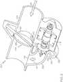
- FIG. 2depicts a cross-sectional view of an exemplary embodiment of a loss recovery assembly 200 suitable for use as the loss recovery assembly 102 in the vehicle system 100 of FIG. 1 .
- the loss recovery assembly 200may be realized as a unitary or integrated component that provides an intermediate portion of the conduit between the fuel cell stack 104 and the exhaust system 110.
- the loss recovery assembly 200includes a fluid conduit 202 which is configured to receive flow 212 of an input fluid (e.g., fluid flow 114) and a valve 206, is positioned in the fluid conduit 202.
- the turbine inlet conduitincludes an inlet 220 which may be defined at least in part by the intake conduit 202 and configured to selectively receive at least a portion of the input fluid flow 212 from the intake conduit 202.
- the turbine wheel 226is mounted on a shaft 230 coupled to an electrical generator 228, which is configured to produce electrical energy when the turbine wheel 226 rotates.
- the illustrated turbine assembly 224includes a volute 232, which substantially surrounds the turbine 226 and supplies the portion of the input fluid flow 212 received via the inlet 220 to the turbine 226.
- the intake conduit 202, the turbine outlet conduit 222, and the volute 232may be defined by an integral housing, which also retains the turbine 226 and the generator 228 to provide the loss recovery assembly 200 with a relatively compact form.
- the valve 206is configurable between multiple positions.
- the valve 206is realized as a butterfly valve that includes a throttle plate 236.
- An adjustment mechanismsuch as an electric motor or throttle cable may be configured to control the valve 206 by adjusting the position of the throttle plate 236, for example, by rotating a shaft 238 to which the throttle plate 236 is coupled about its longitudinal axis.
- a position sensormay detect the position of the throttle plate 236 or the shaft 238 and provide feedback as to the position of the throttle plate 236 such that the position of the valve 206 may be adjusted to achieve a desired intake fluid flow downstream of the valve 206.
- the turbine assembly 224acts as a bypass around the valve 206 when at least a portion of the inlet 220 is not obstructed by the throttle plate 236.
- At least a portion of the input fluid flow 212enters the volute 232 via the inlet 220, which feeds the turbine 226, and the turbine output fluid flow 214 exiting the turbine 226 passes through the turbine outlet conduit 222 and reenters the intake conduit 202 downstream of the valve 206 via an outlet 242.
- the outlet 242may be defined by an opening in the sidewall of the intake conduit 202 downstream of the valve 206. It will be appreciated that the orientation of the throttle plate 236 with respect to the input fluid flow 212 will vary during operation, which, in turn, will vary the amount of the input fluid flow 212 that is redirected or otherwise bypasses the throttle via the turbine assembly 224.
- the loss recovery assembly 102also includes an electronics module 126 that is coupled between the electrical output of the generator 124 and an input node 128 of the vehicle electrical system 130.
- the electronics module 126includes the electrical elements or components that are configured to receive the electrical energy generated by the generator 124 and provide an interface between the output of the generator 124 and the vehicle electrical system 130 for delivering the electrical energy generated by the loss recovery assembly 102 to the vehicle electrical system 130.
- the electronics module 126may include a rectifier configured to rectify the output of the generator 124 to a direct current (DC) voltage level corresponding to the voltage level at the node 128 of the vehicle electrical system 130.
- DCdirect current
- the node 128is an input node for receiving the voltage output from the electrical output of the fuel cell 104, and thus, the electrical output of the loss recovery assembly 102 is coupled to the electrical output of the fuel cell 104 at a common voltage level.
- the generator 124 and the rectification provided by the electronics module 126are designed or otherwise configured to produce an output voltage substantially equal to the output voltage of the fuel cell 104.
- the electronics module 126may include resistors, capacitors, inductors, diodes, transistors, and/or other electrical circuit elements configured to dissipate at least a portion of the electrical energy generated by the generator 124 to prevent a potential overspeed condition with respect to the turbine 122 or an excess energy condition with respect to the vehicle electrical system 130, as described in greater detail below in the context of FIG. 3 .
- the electronics module 126is capable of varying the voltage output provided to the vehicle electrical system 130 by dissipating at least a portion of the electrical energy generated by the generator 124 at the electronics module 126.
- the electronics module 126may include a silicon controller rectifier, switching arrangement, or other electrical component that may be operated to dissipate electrical energy at the electronics module 126 to maintain the output voltage provided to the vehicle electrical system 130 at a target voltage set point provided by an electronic control unit (ECU) 160.
- the electronics module 126may include a field-effect transistor (FET) configured parallel to the generator output that is pulsed, switched, or otherwise activated with a duty cycle that results in the FET dissipating a portion of the generated electrical energy that results in the voltage output by the rectifier of the electronics module 126 being substantially equal to the target voltage set point from the ECU 160.
- FETfield-effect transistor
- the loss recovery assembly 102also includes an electronically-controlled actuation arrangement 109 that is coupled to the valve 106 and configured to control the orientation of the valve 106 with respect to the fluid flow 114 (e.g., the size of the opening provided within the conduit 108) in response to a valve position command.
- the actuation arrangement 109may include one or more cables, linkages, motors, or the like, such as is found with an electronically-controlled throttle.
- the actuation arrangement 109is coupled to the ECU 160 to receive valve position commands from the ECU 160 that result in a desired backpressure for the fluid flow 114 exiting the fuel cell stack 104, and thereby, achieve a desired humidity within the fuel cell stack 104. That said, in other embodiments, the actuation arrangement 109 may be coupled to the electronics module 126, which may act as an intermediary that commands or otherwise controls operation of the actuation arrangement 109 based on signals or instructions received from the ECU 160.
- a compressor assembly 134is provided upstream of the fuel cell 104 to receive intake air (e.g., via an air filter of the like) and compress the air to achieve a desired operation of the fuel cell 104.
- the illustrated compressor assembly 134includes a compressor 136 in the intake fluid flow path upstream of the fuel cell 104, a motor 138 coupled to the compressor 136 (e.g., via a common rotary shaft), and a compressor control module 140 coupled to the motor 138 and configured to operate the motor 138 responsive to commands or instructions received from the ECU 160 to achieve a desired rotational velocity, and thereby compression ratio, for the compressor 136.
- the compressor control module 140may include control hardware (e.g., a microcontroller, a microprocessor, or the like), power conversion hardware (e.g., an inverter), or another suitable combination of electrical components configured to support operation of the compressor motor 138, and thereby the compressor 136, in response to signals or commands received from the ECU 160.
- control hardwaree.g., a microcontroller, a microprocessor, or the like
- power conversion hardwaree.g., an inverter
- the compressor control module 140may include control hardware (e.g., a microcontroller, a microprocessor, or the like), power conversion hardware (e.g., an inverter), or another suitable combination of electrical components configured to support operation of the compressor motor 138, and thereby the compressor 136, in response to signals or commands received from the ECU 160.
- a heat exchanger 142cools the compressed airflow that is provided to the air inlet to the cathode electrode 103 of the fuel cell 104.
- An inlet of the anode electrode 105is coupled to a fuel source, such as hydrogen source 107, to receive or otherwise obtain the fuel that is oxidized into ions and electrons.
- the compressed air input to the cathode electrode 103reacts with the byproducts of the reaction at the anode electrode 105 to provide the fluid flow 114 that then exits the outlet of the cathode electrode 103.
- An electrical output of the fuel cell 104is connected to a corresponding fuel cell voltage input node 128 of the vehicle electrical system 130 to provide electrical energy to the vehicle electrical system 130 as desired.
- the vehicle electrical system 130includes a DC-to-DC power converter 144 having its input connected to the fuel cell voltage input node 128 and its output connected to a voltage bus 145 having a DC voltage level corresponding to the vehicle battery 146.
- the DC-to-DC converter 144converts the voltage level at the input node 128 to a corresponding input electrical current at the DC voltage level of the voltage bus 145.
- the output voltage of the fuel cell 104may be on the order of 100 Volts or more, while the battery 146 has a nominal voltage of about 12 V to about 14 V, where the DC-to-DC converter 144 converts the fuel cell output voltage to the battery voltage level. That said, in some embodiments, the fuel cell output voltage (and also, the output voltage of the recovery assembly 102) may be matched to the battery voltage, in which case, the DC-to-DC converter 144 need not be present.
- one or more additional vehicle electrical components 148may be coupled to the voltage bus 145 to receive input power for their operation.
- the vehicle drive system 150e.g., the drive electronics for an electric traction motor
- the voltage bus 145may be coupled to the voltage bus 145 to receive input electrical power used to provide traction for the vehicle.
- the ECU 160generally represents the engine control unit or another combination of one or more supervisory electronic control units configured to support operation of the vehicle system 100 described herein.
- the ECU 160is coupled to the vehicle drive system 150 and configured to provide commands or instructions for operating the vehicle traction system responsive to driver input or feedback, such as depressing a gas pedal, a brake pedal, or the like. Additionally, the ECU 160 may be coupled to the various vehicle electrical components 148 within the vehicle electrical system 130 to control their operation based on input or selections from a driver or other vehicle occupant, and thereby, control their consumption of electrical power from the voltage bus 145.
- the ECU 160is also coupled to the compressor control module 140, the valve actuation arrangement 109, and the electronics module 126 of the loss recovery assembly 102 to support operations of the compressor 136 and the turbine assembly 120 that achieve a desired operation of the fuel cell 104, as described in greater detail below.
- the ECU 160may also be coupled to the fuel cell 104 or one or more components thereof (e.g., a fuel cell controller, humidity sensors, pressure sensors, or the like) that are configured to support the processes, tasks, and operations described herein.
- the ECU 160may also be coupled to the hydrogen source 107 to control or otherwise influence the amount or rate of the input fuel flow to the anode inlet of the fuel cell stack 104.
- FIG. 3depicts an exemplary embodiment of a management process 300 suitable for implementation in a vehicle system to regulate the humidity and airflow experienced by an electrode of a fuel cell stack to achieve a desired operation of the fuel cell stack.
- a management process 300suitable for implementation in a vehicle system to regulate the humidity and airflow experienced by an electrode of a fuel cell stack to achieve a desired operation of the fuel cell stack.
- the following descriptionmay refer to elements mentioned above in connection with FIGS. 1-2 .
- portions of the management process 300may be performed by different elements of the vehicle system 100, such as, the ECU 160, the electronics module 126, the actuation arrangement 109, the compressor control module 140, or the fuel cell stack 104.
- management process 300may include any number of additional or alternative tasks, the tasks need not be performed in the illustrated order and/or the tasks may be performed concurrently, and/or the management process 300 may be incorporated into a more comprehensive procedure or process having additional functionality not described in detail herein. Moreover, one or more of the tasks shown and described in the context of FIG. 3 could be omitted from a practical embodiment of the management process 300 as long as the intended overall functionality remains intact.
- the management process 300begins by operating the compressor assembly to achieve the desired input airflow to the cathode electrode of the fuel cell stack (task 302).
- the ECU 160commands, signals, or otherwise instructs the compressor control module 140 to operate the motor 138, and thereby the compressor 134, to achieve a desired air pressure at the inlet to the cathode 103.
- the ECU 160may receive feedback indicative of one or more of the ambient air pressure, the fuel flow rate at the inlet to the anode 105, the current power consumption associated with the voltage bus 145 (e.g., the power needs of the vehicle drive system 150 and/or the vehicle electrical components 148), and based thereon, determine an optimal input pressure for the input airflow to the cathode 103 to achieve a desired power output. From there, the ECU 160 calculates or otherwise determines commands or instructions for operating the compressor 136 of the compressor assembly 134 to achieve the compression ratio that results in that optimal input pressure at the cathode inlet.
- the components of the compressor assembly 134may be designed or otherwise optimized for an average or nominal airflow to the fuel cell stack 104.
- the compressor 136may be sized to achieve a desired amount of compression, with the compressor motor 138 then being matched to the compressor input power for achieving that amount of compression.
- the illustrated management process 300continues by receiving or otherwise obtaining information indicative of the current humidity of the fuel cell stack and operating the valve of the loss recovery system based on the current humidity information (tasks 304, 306).
- the fuel cell stack 104may include a humidity sensor configured to measure or otherwise quantify the current humidity of the cathode 103 of the fuel cell 104.
- the ECU 160may be coupled to a humidity sensor (either directly or indirectly via a fuel cell control module) to receive or otherwise obtain a current measurement value for the humidity of the cathode 103, and based thereon, determine how to operate the valve 106 of the loss recovery assembly 102.
- the electronics module 126may be coupled to the fuel cell 104 to determine how to operate the valve 106 of the loss recovery assembly 102 based on the current humidity information, or a fuel cell control module determine whether humidity should be increased or decreased or otherwise how to operate the valve 106 and provide a corresponding indication to the ECU 160 or electronics module 126.
- the ECU 160determines whether the current humidity is less than or greater than a target humidity value, and operates the valve 106 based on the difference. For example, based on one or more factors, the ECU 160 may determine an optimal humidity level for operating the fuel cell 104 most efficiently, and then compare the current humidity measurement value to that targeted humidity value.
- the ECU 160signals, commands, or otherwise instructs the actuation arrangement 109 to adjust the orientation of the valve 106 to increase the size of the opening within the conduit 108 (or decrease the angle of the valve 106 with respect to the flow 114), thereby reducing the backpressure, which, in turn, facilitates a less restricted cathode exit flow 114 that is capable of lowering the humidity of the cathode 103.
- the ECU 160signals, commands, or otherwise instructs the actuation arrangement 109 to adjust the orientation of the valve 106 to decrease the size of the opening within the conduit 108 (or increase the angle of the valve 106 with respect to the flow 114), thereby increasing the backpressure, which, in turn, restricts the cathode exit flow 114 to facilitate increasing or maintaining the humidity of the cathode 103.
- the ECU 160may calculate the amount by which the angle of the valve 106 should be adjusted based on the magnitude of the difference between the current humidity value and the target humidity value and the mass flow rate associated with the current exit flow 114.
- the ECU 160may determine whether the current humidity is less than or equal to a minimum humidity threshold, or alternatively, greater than a maximum humidity threshold. In response to determining the current humidity is less than or equal to the minimum humidity threshold, the ECU 160 signals, commands, or otherwise instructs the actuation arrangement 109 to adjust the orientation of the valve 106 to decrease the size of the opening within the conduit 108 and increase the backpressure. Conversely, in response to determining the current humidity is less than or equal to the minimum humidity threshold, the ECU 160 signals, commands, or otherwise instructs the actuation arrangement 109 to adjust the orientation of the valve 106 to increase the size of the opening within the conduit 108 and decrease the backpressure.
- the management process 300continues by detecting or otherwise identifying the presence of a potential generator overspeed condition, and in response, operates the electronics module of the loss recovery assembly to dissipate energy to mitigate the potential overspeed condition (tasks 308, 310).
- the turbine input flow 116may cause the turbine 122 to rotate at a speed that could exceed the design limit of the generator 124.
- the ECU 160may signal, command, or otherwise instruct the electronics module 126 to effectively short-circuit the electrical output of the generator 124 through a resistive path or otherwise increase the electrical loading of the generator 124, thereby preventing an overspeed condition. For example, based on the current power consumption associated with the voltage bus 145 being less than the combined power output of the fuel cell 104 and the generator 124, the ECU 160 may determine a potential overspeed condition exists, and in response, signal the electronics module 126 to dissipate at least a portion of the electrical output from the generator 124 to mitigate the potential overspeed condition.
- the ECU 160may receive a generator speed feedback signal and detect a potential overspeed condition based on the current generator speed being greater than a threshold value. In response to an overspeed condition, the ECU 160 may reduce the target voltage set point provided to the electronics module 126 from the current voltage output of the fuel cell 104 at node 128 to some lesser value that results in the electronics module 126 dissipating at least a portion of the generated electrical energy.
- the management process 300may detect or otherwise identify the presence of a potential excess energy condition, and in response, operate the electronics module of the loss recovery assembly to dissipate energy to mitigate the potential excess energy condition (tasks 310, 312). For example, depending on the orientation of the valve 106 and the mass flow rate of the cathode exit flow 114, the power generated by the generator 124, when combined with the power output provided by the fuel cell 104, may be greater than the power handling capability of the voltage bus 145 (e.g., the battery 146 is fully charged, vehicle electrical components 148 are turned off, and the like).
- the ECU 160signals the electronics module 126 to dissipate at least a portion of the electrical output from the generator 124 (e.g., by reducing the target voltage set point) to reduce the input power to the vehicle electrical system 130 at node 128.
- the ECU 160may calculate, estimate, or otherwise determine the amount of excess power to be dissipated based on the difference between the total input power (e.g., the sum of the fuel cell 104 power output and the generator 124 power output) and the current power handling capability of the voltage bus 145.
- the ECU 160then operates the electronics module 126 of the loss recovery assembly 102 to dissipate the amount of excess power.
- the target voltage set point provided to the electronics module 126is set to a voltage that is less than or equal to the voltage of the voltage bus 145, thereby ensuring that the turbine assembly 120 does not contribute any current to the voltage bus 145.
- the management process 300operates the electronics module of the loss recovery assembly to distribute the generated electrical energy to the vehicle electrical system (task 314).
- the ECU 160signals or otherwise commands the electronics module 126 to output a voltage substantially equal to the fuel cell output voltage at node 128 (e.g., by setting a target voltage set point to the fuel cell output voltage).
- the ECU 160may be coupled to the fuel cell voltage input node 128 or the fuel cell voltage output to measure the current fuel cell voltage output, and based thereon, the ECU 160 may command the electronics module 126 for a target voltage set point equal to the current fuel cell voltage measurement.
- the electrical power generated by the turbine assembly 120is provided to the input node 128 of the vehicle electrical system 130 at the voltage level of the fuel cell 104 and converted to the bus voltage level by the DC-to-DC converter 144 and distributed via the voltage bus 145. It is noted that in embodiments where the output voltage at the fuel cell input node 128 is greater than the bus voltage, the size of the generator 124 may be reduced by designing the generator 124 for the fuel cell output voltage rather than the lower bus voltage.
- FIG. 4depicts an exemplary embodiment of an electronics module 400 suitable for use as the electronics module 126 in the turbine assembly 120 of FIG. 1 in conjunction with the management process 300 of FIG. 3 .
- the electronics module 400includes power electronics 402 coupled between the output of the generator 124 and the input node 128 of the vehicle electrical system 130, and the power electronics 402 generally represent the hardware components of the electronics module 400 that are configured to filter, rectify, or otherwise process the electrical energy output by the generator 124 and deliver the generated electrical energy to the vehicle electrical system 130.
- the power electronics 402has an input 406 coupled to the output of the generator 124, an output 408 coupled to the input node 128 to the vehicle electrical system 130, and the power electronics 402 convert input electrical energy received from the generator 124 at the input 406 to a voltage level at output 408 corresponding to a target voltage set point.
- the power electronics 402may include circuitry configured to selectively dissipate the generated electrical energy in response to commands from a control module 404 of the electronics module 400.
- the control module 404generally represents the hardware, processing logic or other components of the electronics module 400 that are coupled to the ECU 160 and configured to support operations of the electronics module 126 described herein.
- the control module 404may include or otherwise be realized as a processor, a controller, a microprocessor, a microcontroller, an application specific integrated circuit, a field programmable gate array, or any suitable programmable logic device.
- the control module 404receives indication of the target voltage set point from the ECU 160 and operates the power electronics 402 to convert the electrical energy received from the generator 124 at the input 406 to a voltage level substantially equal to the target voltage set point at the output 408.
- the control module 404operates circuitry of the power electronics 402 to dissipate at least a portion of the electrical power recovered by the loss recovery assembly 102.
- the subject matter described hereinallows for the loss recovery assembly 102 to be designed and packaged independently of the compressor assembly 134.
- the plumbing from the cathode outlet downstream to the exhaust system 110 via the loss recovery assembly 102may be simplified.
- the turbine 122 and the generator 124may be designed and sized independently of the compressor assembly 134, thereby allowing them to be optimized for the nominal cathode exit mass flow rate.
- An electronics module 126, 400 of the loss recovery assembly 102may be utilized to load the generator 124 as needed by dissipating generated electrical energy to prevent generator overspeed.
- the electronics module 126, 400can also be utilized to dissipate generated electrical energy to prevent overcharging the vehicle battery 146 or otherwise overpowering the vehicle electrical system 130.
- the turbine 122may be realized using a fixed geometry, arranged effectively in parallel with the valve 106, and sized with greater degrees of freedom (e.g., independently of the generator 124 or the vehicle system 100) to achieve efficient operation for the typical cathode exit flow 114. Additionally, the generator 124 may then be sized for the fuel cell output voltage at node 128 (e.g., rather than the voltage of the voltage bus 145 or battery 146), thereby allowing the generator 124 size to be reduced, which, in concert with the design of the turbine 122 provides greater degrees of freedom from a packaging perspective.
- the compressor assembly 134can similarly be designed independent of the turbine assembly 120, thereby providing greater degrees of freedom with respect to efficiency, plumbing, or packaging upstream of the fuel cell 104.
- embodiments of the subject matter described hereincan be stored on, encoded on, or otherwise embodied by any suitable non-transitory computer-readable medium as computer-executable instructions or data stored thereon that, when executed (e.g., by a control module or other processing system), facilitate the processes described above.
- Coupledmeans that one element/node/feature is directly or indirectly joined to (or directly or indirectly communicates with) another element/node/feature, and not necessarily mechanically.
- drawingsmay depict one exemplary arrangement of elements, additional intervening elements, devices, features, or components may be present in an embodiment of the depicted subject matter.
- certain terminologymay also be used in the following description for the purpose of reference only, and thus are not intended to be limiting. For example, the terms “first,” “second,” and other such numerical terms referring to structures do not imply a sequence or order unless clearly indicated by the context.
Landscapes
- Engineering & Computer Science (AREA)
- Life Sciences & Earth Sciences (AREA)
- Sustainable Energy (AREA)
- Sustainable Development (AREA)
- Chemical Kinetics & Catalysis (AREA)
- Manufacturing & Machinery (AREA)
- Chemical & Material Sciences (AREA)
- Electrochemistry (AREA)
- General Chemical & Material Sciences (AREA)
- Power Engineering (AREA)
- Mechanical Engineering (AREA)
- Transportation (AREA)
- Fuel Cell (AREA)
- Control Of Turbines (AREA)
- Electric Propulsion And Braking For Vehicles (AREA)
Description
- The subject matter described herein relates generally to flow control systems, and more particularly, to regulating fuel cell backpressure or humidity in conjunction with a flow control assembly that recovers energy resulting from the regulation.
- In recent years, fuel cells have been utilized in an increasing number of applications. For example, a fuel cell stack may be utilized to supply electrical power for a traction motor in an electric vehicle. Typically, compressed air is supplied to one or more of the electrodes of the fuel cell to achieve efficient operation of the fuel cell. This airflow presents an opportunity for energy recovery downstream of the fuel cell. Accordingly, prior art systems have been developed that utilize a turbine to recover energy from the flow exiting the fuel cell. Traditionally, the turbine is mechanically coupled to the input air compressor via a common rotary shaft to leverage energy recovered by the turbine to power the compressor. However, this can increase the complexity when designing the turbocompressor assembly, and also, impose certain packaging or plumbing constraints when installed in an automotive vehicle. Additionally, unregulated airflow through the fuel cell can undesirably reduce the humidity of the fuel cell stack. Accordingly, it is desirable to provide a manner of recovering energy from the fuel cell stack that also affords control of the fuel cell airflow while also reducing packaging or plumbing constraints without compromising efficiency.
DE102012007377 (A1 ) discloses a fuel cell system for a mobile application which has a pulsation device in region of air flow to and / or from the cathode region for changing pressure, velocity and / or volume flow of air flow.JP2003039941 (A - The present invention provides for a system and corresponding method as claimed in the accompanying claims. In particular, turbine assemblies, throttle loss recovery systems, and related vehicle electrical systems and operating methods are provided. One exemplary vehicle system includes a fuel cell stack, a flow control valve to regulate a fluid flow exiting the fuel cell stack, and a flow control assembly parallel to the flow control valve to generate electrical energy in response to a bypass portion of the fluid flow bypassing the flow control valve based on an orientation of the flow control valve with respect to the fluid flow.
- Another exemplary embodiment of a vehicle system includes a fuel cell stack, a conduit for an exit fluid flow from the fuel cell stack, a valve disposed within the conduit, and a turbine assembly to receive a bypass portion of the exit fluid flow based on an orientation of the valve with respect to the conduit.
- An exemplary method of operating a turbine assembly involves obtaining humidity information for a fuel cell stack providing electrical power at an output voltage at an input node to a vehicle electrical system and adjusting an orientation of a valve downstream of the fuel cell stack based on the humidity information. The orientation of the valve influences electrical energy generated by the turbine assembly, and the method further provides the electrical energy from the turbine assembly to the input node at a voltage level corresponding to a voltage output of the fuel cell stack.
- Embodiments of the subject matter will hereinafter be described in conjunction with the following drawing figures, wherein like numerals denote like elements, and:
FIG. 1 is a block diagram of a vehicle system including a loss recovery assembly downstream of a fuel cell stack in one or more exemplary embodiments;FIG. 2 is a cross-sectional view of a loss recovery assembly suitable for use in the vehicle system ofFIG. 1 in an exemplary embodiment;FIG. 3 is a flow diagram of an exemplary management process suitable for use with the vehicle system ofFIG. 1 in accordance with one or more embodiments; andFIG. 4 is a block diagram of an exemplary turbine assembly electronics module suitable for use with the loss recovery assembly ofFIG. 1 in conjunction with the management process ofFIG. 3 in accordance with one or more embodiments.- Embodiments of the subject matter described herein relate to vehicle systems that include a flow control assembly that functions as a bypass for fluid flow around a flow control valve to generate energy from the bypassing fluid flow.
- In exemplary embodiments described herein, the flow control valve is disposed within a conduit between a fuel cell stack and a vehicle exhaust system to regulate a fluid flow exiting the fuel cell stack, and thereby, regulate or otherwise manage the humidity of the fuel cell stack. The turbine assembly provides a fluid path that is parallel to the intermediate portion of the conduit having the valve disposed therein, such that the orientation of the valve with respect to the fluid flow influences the amount of the exiting fluid flow that bypasses the valve through the turbine. In exemplary embodiments, the generator output is coupled to the electrical output of the fuel cell stack to output generated electrical energy resulting from the bypassing portion of the fuel cell exit flow at a voltage level corresponding to the fuel cell output voltage. In exemplary embodiments, an electronics module is provided between the generator output and the fuel cell voltage output to control distribution of the generated electrical energy. In this regard, to prevent potential generator overspeed or excess energy generation, the electronics module may dissipate at least a portion of the generated electrical energy, or in some cases, output the generated electrical energy at a voltage that is less than vehicle electrical system bus voltage (or alternatively, less than the fuel cell output voltage) to effectively divert the generated electrical energy away from the vehicle electrical system.
FIG. 1 depicts an exemplary embodiment of avehicle system 100 suitable for use with an automotive vehicle that includes aloss recovery assembly 102 configured to modulate the flow of air downstream of afuel cell stack 104, and thereby, regulate the backpressure of the airflow through thefuel cell stack 104 while also recovering energy from the exiting airflow. For the sake of brevity, thefuel cell stack 104 may alternatively be referred to herein as simply the fuel cell, however, it should be appreciated that in practice thefuel cell stack 104 may actually include a plurality of individual fuel cells which are stacked or otherwise configured to achieve a desired output power level.- As illustrated, the
loss recovery assembly 102 includes a valve 106 (or throttle) disposed within aconduit 108 for air exiting thefuel cell stack 104 that is to be supplied to avehicle exhaust system 110. Aconduit 112 that adjoins the fuel cell outlet conduit 108 upstream of thevalve 106 has an inlet configured to selectively receive at least aportion 116 of thefluid flow 114 exiting thefuel cell stack 104 that bypasses thevalve 106 in a manner that is influenced by the orientation (or angle) of thevalve 106 with respect to thefluid flow 114. In this regard, as the angle of thevalve 106 with respect to thefluid flow 114 increases to restrict theexiting fluid flow 114 and increase the backpressure, the amount offluid flow 116 bypassing thevalve 106 through theconduit 112 increases, which, in turn, increases the potential electrical energy that may be generated by theloss recovery assembly 102. Conversely, as the angle of thevalve 106 with respect to the exitingfluid flow 114 decreases to reduce the fuel cell backpressure, the amount ofbypass fluid flow 116 entering theconduit 112 decreases. - The outlet of the
conduit 112 is coupled to the inlet (or input) of aturbine assembly 120 to establish fluid communication between the fuelcell exhaust conduit 108 upstream of thevalve 106 and the inlet of aturbine 122 of theturbine assembly 120. In this regard, thebypass fluid flow 116 functions as the turbine input fluid flow that passes through the volute, nozzle, or and/or vanes of theturbine 122 and impacts the blades (or wheel) of theturbine 122 to rotate theturbine 122. In one or more exemplary embodiments, theturbine 122 is realized as a fixed geometry turbine. Theturbine assembly 120 also includes an electrical generator 124 coupled to theturbine 122 via a shaft, and the electrical generator 124 generates electrical energy in response to the rotation of the shaft caused by the turbineinput fluid flow 116. Theloss recovery assembly 102 includes anotherconduit 118 having its inlet coupled to the outlet of theturbine 122 and its outlet coupled to the fuelcell exhaust conduit 108 downstream of thevalve 106 to establish fluid communication for the turbine output fluid flow. The turbine output fluid flow from theturbine 122 recombines with the remaining portion of the fuel cell exhaust flow that passes thevalve 106 to provide the input fluid flow to thevehicle exhaust system 110. FIG. 2 depicts a cross-sectional view of an exemplary embodiment of aloss recovery assembly 200 suitable for use as theloss recovery assembly 102 in thevehicle system 100 ofFIG. 1 . In this regard, in some embodiments, theloss recovery assembly 200 may be realized as a unitary or integrated component that provides an intermediate portion of the conduit between thefuel cell stack 104 and theexhaust system 110.- The
loss recovery assembly 200 includes afluid conduit 202 which is configured to receiveflow 212 of an input fluid (e.g., fluid flow 114) and avalve 206, is positioned in thefluid conduit 202. In the illustrated embodiment, the turbine inlet conduit includes aninlet 220 which may be defined at least in part by theintake conduit 202 and configured to selectively receive at least a portion of theinput fluid flow 212 from theintake conduit 202. Theturbine wheel 226 is mounted on ashaft 230 coupled to anelectrical generator 228, which is configured to produce electrical energy when theturbine wheel 226 rotates. The illustratedturbine assembly 224 includes avolute 232, which substantially surrounds theturbine 226 and supplies the portion of theinput fluid flow 212 received via theinlet 220 to theturbine 226. As illustrated, in some embodiments, theintake conduit 202, theturbine outlet conduit 222, and thevolute 232 may be defined by an integral housing, which also retains theturbine 226 and thegenerator 228 to provide theloss recovery assembly 200 with a relatively compact form. - In exemplary embodiments, the
valve 206 is configurable between multiple positions. For instance, in some embodiments, thevalve 206 is realized as a butterfly valve that includes athrottle plate 236. An adjustment mechanism such as an electric motor or throttle cable may be configured to control thevalve 206 by adjusting the position of thethrottle plate 236, for example, by rotating ashaft 238 to which thethrottle plate 236 is coupled about its longitudinal axis. In practice, a position sensor may detect the position of thethrottle plate 236 or theshaft 238 and provide feedback as to the position of thethrottle plate 236 such that the position of thevalve 206 may be adjusted to achieve a desired intake fluid flow downstream of thevalve 206. In this regard,FIG. 2 depicts thevalve 206 opened to a point at which theinlet 220 to theturbine 226 is substantially fully unblocked. Thus, theturbine assembly 224 acts as a bypass around thevalve 206 when at least a portion of theinlet 220 is not obstructed by thethrottle plate 236. At least a portion of theinput fluid flow 212 enters thevolute 232 via theinlet 220, which feeds theturbine 226, and the turbineoutput fluid flow 214 exiting theturbine 226 passes through theturbine outlet conduit 222 and reenters theintake conduit 202 downstream of thevalve 206 via anoutlet 242. As illustrated, theoutlet 242 may be defined by an opening in the sidewall of theintake conduit 202 downstream of thevalve 206. It will be appreciated that the orientation of thethrottle plate 236 with respect to theinput fluid flow 212 will vary during operation, which, in turn, will vary the amount of theinput fluid flow 212 that is redirected or otherwise bypasses the throttle via theturbine assembly 224. - Referring again to
FIG. 1 , theloss recovery assembly 102 also includes anelectronics module 126 that is coupled between the electrical output of the generator 124 and aninput node 128 of the vehicleelectrical system 130. Theelectronics module 126 includes the electrical elements or components that are configured to receive the electrical energy generated by the generator 124 and provide an interface between the output of the generator 124 and the vehicleelectrical system 130 for delivering the electrical energy generated by theloss recovery assembly 102 to the vehicleelectrical system 130. For example, theelectronics module 126 may include a rectifier configured to rectify the output of the generator 124 to a direct current (DC) voltage level corresponding to the voltage level at thenode 128 of the vehicleelectrical system 130. In exemplary embodiments, thenode 128 is an input node for receiving the voltage output from the electrical output of thefuel cell 104, and thus, the electrical output of theloss recovery assembly 102 is coupled to the electrical output of thefuel cell 104 at a common voltage level. Thus, the generator 124 and the rectification provided by theelectronics module 126 are designed or otherwise configured to produce an output voltage substantially equal to the output voltage of thefuel cell 104. - Additionally, in some embodiments, the
electronics module 126 may include resistors, capacitors, inductors, diodes, transistors, and/or other electrical circuit elements configured to dissipate at least a portion of the electrical energy generated by the generator 124 to prevent a potential overspeed condition with respect to theturbine 122 or an excess energy condition with respect to the vehicleelectrical system 130, as described in greater detail below in the context ofFIG. 3 . In some embodiments, theelectronics module 126 is capable of varying the voltage output provided to the vehicleelectrical system 130 by dissipating at least a portion of the electrical energy generated by the generator 124 at theelectronics module 126. In this regard, theelectronics module 126 may include a silicon controller rectifier, switching arrangement, or other electrical component that may be operated to dissipate electrical energy at theelectronics module 126 to maintain the output voltage provided to the vehicleelectrical system 130 at a target voltage set point provided by an electronic control unit (ECU) 160. For example, theelectronics module 126 may include a field-effect transistor (FET) configured parallel to the generator output that is pulsed, switched, or otherwise activated with a duty cycle that results in the FET dissipating a portion of the generated electrical energy that results in the voltage output by the rectifier of theelectronics module 126 being substantially equal to the target voltage set point from theECU 160. - In the illustrated embodiment, the
loss recovery assembly 102 also includes an electronically-controlledactuation arrangement 109 that is coupled to thevalve 106 and configured to control the orientation of thevalve 106 with respect to the fluid flow 114 (e.g., the size of the opening provided within the conduit 108) in response to a valve position command. In this regard, theactuation arrangement 109 may include one or more cables, linkages, motors, or the like, such as is found with an electronically-controlled throttle. In the illustrated embodiment, theactuation arrangement 109 is coupled to theECU 160 to receive valve position commands from theECU 160 that result in a desired backpressure for thefluid flow 114 exiting thefuel cell stack 104, and thereby, achieve a desired humidity within thefuel cell stack 104. That said, in other embodiments, theactuation arrangement 109 may be coupled to theelectronics module 126, which may act as an intermediary that commands or otherwise controls operation of theactuation arrangement 109 based on signals or instructions received from theECU 160. - Still referring to
FIG. 1 , as illustrated, acompressor assembly 134 is provided upstream of thefuel cell 104 to receive intake air (e.g., via an air filter of the like) and compress the air to achieve a desired operation of thefuel cell 104. The illustratedcompressor assembly 134 includes acompressor 136 in the intake fluid flow path upstream of thefuel cell 104, amotor 138 coupled to the compressor 136 (e.g., via a common rotary shaft), and acompressor control module 140 coupled to themotor 138 and configured to operate themotor 138 responsive to commands or instructions received from theECU 160 to achieve a desired rotational velocity, and thereby compression ratio, for thecompressor 136. In this regard, thecompressor control module 140 may include control hardware (e.g., a microcontroller, a microprocessor, or the like), power conversion hardware (e.g., an inverter), or another suitable combination of electrical components configured to support operation of thecompressor motor 138, and thereby thecompressor 136, in response to signals or commands received from theECU 160. - Downstream of the
compressor assembly 134, aheat exchanger 142 cools the compressed airflow that is provided to the air inlet to thecathode electrode 103 of thefuel cell 104. An inlet of theanode electrode 105 is coupled to a fuel source, such ashydrogen source 107, to receive or otherwise obtain the fuel that is oxidized into ions and electrons. The compressed air input to thecathode electrode 103 reacts with the byproducts of the reaction at theanode electrode 105 to provide thefluid flow 114 that then exits the outlet of thecathode electrode 103. An electrical output of thefuel cell 104 is connected to a corresponding fuel cellvoltage input node 128 of the vehicleelectrical system 130 to provide electrical energy to the vehicleelectrical system 130 as desired. - In the illustrated embodiment, the vehicle
electrical system 130 includes a DC-to-DC power converter 144 having its input connected to the fuel cellvoltage input node 128 and its output connected to avoltage bus 145 having a DC voltage level corresponding to thevehicle battery 146. In this regard, when the DC voltage level output by thefuel cell 104 is different from the DC voltage level of thebattery 146, the DC-to-DC converter 144 converts the voltage level at theinput node 128 to a corresponding input electrical current at the DC voltage level of thevoltage bus 145. For example, the output voltage of thefuel cell 104 may be on the order of 100 Volts or more, while thebattery 146 has a nominal voltage of about 12 V to about 14 V, where the DC-to-DC converter 144 converts the fuel cell output voltage to the battery voltage level. That said, in some embodiments, the fuel cell output voltage (and also, the output voltage of the recovery assembly 102) may be matched to the battery voltage, in which case, the DC-to-DC converter 144 need not be present. In the illustrated embodiment, one or more additional vehicleelectrical components 148 may be coupled to thevoltage bus 145 to receive input power for their operation. Additionally, the vehicle drive system 150 (e.g., the drive electronics for an electric traction motor) may be coupled to thevoltage bus 145 to receive input electrical power used to provide traction for the vehicle. - The
ECU 160 generally represents the engine control unit or another combination of one or more supervisory electronic control units configured to support operation of thevehicle system 100 described herein. TheECU 160 is coupled to thevehicle drive system 150 and configured to provide commands or instructions for operating the vehicle traction system responsive to driver input or feedback, such as depressing a gas pedal, a brake pedal, or the like. Additionally, theECU 160 may be coupled to the various vehicleelectrical components 148 within the vehicleelectrical system 130 to control their operation based on input or selections from a driver or other vehicle occupant, and thereby, control their consumption of electrical power from thevoltage bus 145. TheECU 160 is also coupled to thecompressor control module 140, thevalve actuation arrangement 109, and theelectronics module 126 of theloss recovery assembly 102 to support operations of thecompressor 136 and theturbine assembly 120 that achieve a desired operation of thefuel cell 104, as described in greater detail below. In this regard, although not depicted inFIG. 1 for purposes of clarity, in practice, theECU 160 may also be coupled to thefuel cell 104 or one or more components thereof (e.g., a fuel cell controller, humidity sensors, pressure sensors, or the like) that are configured to support the processes, tasks, and operations described herein. Moreover, in some embodiments, theECU 160 may also be coupled to thehydrogen source 107 to control or otherwise influence the amount or rate of the input fuel flow to the anode inlet of thefuel cell stack 104. FIG. 3 depicts an exemplary embodiment of amanagement process 300 suitable for implementation in a vehicle system to regulate the humidity and airflow experienced by an electrode of a fuel cell stack to achieve a desired operation of the fuel cell stack. For illustrative purposes, the following description may refer to elements mentioned above in connection withFIGS. 1-2 . In practice, portions of themanagement process 300 may be performed by different elements of thevehicle system 100, such as, theECU 160, theelectronics module 126, theactuation arrangement 109, thecompressor control module 140, or thefuel cell stack 104. It should be appreciated that practical embodiments of themanagement process 300 may include any number of additional or alternative tasks, the tasks need not be performed in the illustrated order and/or the tasks may be performed concurrently, and/or themanagement process 300 may be incorporated into a more comprehensive procedure or process having additional functionality not described in detail herein. Moreover, one or more of the tasks shown and described in the context ofFIG. 3 could be omitted from a practical embodiment of themanagement process 300 as long as the intended overall functionality remains intact.- In exemplary embodiments, the
management process 300 begins by operating the compressor assembly to achieve the desired input airflow to the cathode electrode of the fuel cell stack (task 302). In this regard, theECU 160 commands, signals, or otherwise instructs thecompressor control module 140 to operate themotor 138, and thereby thecompressor 134, to achieve a desired air pressure at the inlet to thecathode 103. For example, theECU 160 may receive feedback indicative of one or more of the ambient air pressure, the fuel flow rate at the inlet to theanode 105, the current power consumption associated with the voltage bus 145 (e.g., the power needs of thevehicle drive system 150 and/or the vehicle electrical components 148), and based thereon, determine an optimal input pressure for the input airflow to thecathode 103 to achieve a desired power output. From there, theECU 160 calculates or otherwise determines commands or instructions for operating thecompressor 136 of thecompressor assembly 134 to achieve the compression ratio that results in that optimal input pressure at the cathode inlet. It should be noted that by virtue of thecompressor assembly 134 being physically and electrically separate from theturbine assembly 120, the components of the compressor assembly 134 (namely thecompressor 136 and the motor 138) may be designed or otherwise optimized for an average or nominal airflow to thefuel cell stack 104. In other words, thecompressor 136 may be sized to achieve a desired amount of compression, with thecompressor motor 138 then being matched to the compressor input power for achieving that amount of compression. - The illustrated
management process 300 continues by receiving or otherwise obtaining information indicative of the current humidity of the fuel cell stack and operating the valve of the loss recovery system based on the current humidity information (tasks 304, 306). For example, thefuel cell stack 104 may include a humidity sensor configured to measure or otherwise quantify the current humidity of thecathode 103 of thefuel cell 104. TheECU 160 may be coupled to a humidity sensor (either directly or indirectly via a fuel cell control module) to receive or otherwise obtain a current measurement value for the humidity of thecathode 103, and based thereon, determine how to operate thevalve 106 of theloss recovery assembly 102. In alternative embodiments, theelectronics module 126 may be coupled to thefuel cell 104 to determine how to operate thevalve 106 of theloss recovery assembly 102 based on the current humidity information, or a fuel cell control module determine whether humidity should be increased or decreased or otherwise how to operate thevalve 106 and provide a corresponding indication to theECU 160 orelectronics module 126. - In one embodiment, the
ECU 160 determines whether the current humidity is less than or greater than a target humidity value, and operates thevalve 106 based on the difference. For example, based on one or more factors, theECU 160 may determine an optimal humidity level for operating thefuel cell 104 most efficiently, and then compare the current humidity measurement value to that targeted humidity value. When the current humidity is greater than the optimal humidity, theECU 160 signals, commands, or otherwise instructs theactuation arrangement 109 to adjust the orientation of thevalve 106 to increase the size of the opening within the conduit 108 (or decrease the angle of thevalve 106 with respect to the flow 114), thereby reducing the backpressure, which, in turn, facilitates a less restrictedcathode exit flow 114 that is capable of lowering the humidity of thecathode 103. Alternatively, when the current humidity is less than the optimal humidity, theECU 160 signals, commands, or otherwise instructs theactuation arrangement 109 to adjust the orientation of thevalve 106 to decrease the size of the opening within the conduit 108 (or increase the angle of thevalve 106 with respect to the flow 114), thereby increasing the backpressure, which, in turn, restricts thecathode exit flow 114 to facilitate increasing or maintaining the humidity of thecathode 103. In some embodiments, theECU 160 may calculate the amount by which the angle of thevalve 106 should be adjusted based on the magnitude of the difference between the current humidity value and the target humidity value and the mass flow rate associated with thecurrent exit flow 114. - In another embodiment, the
ECU 160 may determine whether the current humidity is less than or equal to a minimum humidity threshold, or alternatively, greater than a maximum humidity threshold. In response to determining the current humidity is less than or equal to the minimum humidity threshold, theECU 160 signals, commands, or otherwise instructs theactuation arrangement 109 to adjust the orientation of thevalve 106 to decrease the size of the opening within theconduit 108 and increase the backpressure. Conversely, in response to determining the current humidity is less than or equal to the minimum humidity threshold, theECU 160 signals, commands, or otherwise instructs theactuation arrangement 109 to adjust the orientation of thevalve 106 to increase the size of the opening within theconduit 108 and decrease the backpressure. - Still referring to
FIG. 3 , in exemplary embodiments, themanagement process 300 continues by detecting or otherwise identifying the presence of a potential generator overspeed condition, and in response, operates the electronics module of the loss recovery assembly to dissipate energy to mitigate the potential overspeed condition (tasks 308, 310). In this regard, when theturbine 122 has a fixed geometry, at certain orientations of thevalve 106 in combination of the mass flow rate of thecathode exit flow 114, theturbine input flow 116 may cause theturbine 122 to rotate at a speed that could exceed the design limit of the generator 124. Thus, to prevent potential generator overspeed, theECU 160 may signal, command, or otherwise instruct theelectronics module 126 to effectively short-circuit the electrical output of the generator 124 through a resistive path or otherwise increase the electrical loading of the generator 124, thereby preventing an overspeed condition. For example, based on the current power consumption associated with thevoltage bus 145 being less than the combined power output of thefuel cell 104 and the generator 124, theECU 160 may determine a potential overspeed condition exists, and in response, signal theelectronics module 126 to dissipate at least a portion of the electrical output from the generator 124 to mitigate the potential overspeed condition. In some embodiments, theECU 160 may receive a generator speed feedback signal and detect a potential overspeed condition based on the current generator speed being greater than a threshold value. In response to an overspeed condition, theECU 160 may reduce the target voltage set point provided to theelectronics module 126 from the current voltage output of thefuel cell 104 atnode 128 to some lesser value that results in theelectronics module 126 dissipating at least a portion of the generated electrical energy. - Additionally, the
management process 300 may detect or otherwise identify the presence of a potential excess energy condition, and in response, operate the electronics module of the loss recovery assembly to dissipate energy to mitigate the potential excess energy condition (tasks 310, 312). For example, depending on the orientation of thevalve 106 and the mass flow rate of thecathode exit flow 114, the power generated by the generator 124, when combined with the power output provided by thefuel cell 104, may be greater than the power handling capability of the voltage bus 145 (e.g., thebattery 146 is fully charged, vehicleelectrical components 148 are turned off, and the like). Thus, to prevent overcharging of thebattery 146 or otherwise providing excess energy to the vehicleelectrical system 130, theECU 160 signals theelectronics module 126 to dissipate at least a portion of the electrical output from the generator 124 (e.g., by reducing the target voltage set point) to reduce the input power to the vehicleelectrical system 130 atnode 128. For example, based on the current speed of the vehicle (or the current loading of the vehicle drive system 150), the current state of charge and/or output voltage of thebattery 146, the current output power of thefuel cell 104, the orientation of thevalve 106, and the mass flow rate of thecathode exit flow 114, theECU 160 may calculate, estimate, or otherwise determine the amount of excess power to be dissipated based on the difference between the total input power (e.g., the sum of thefuel cell 104 power output and the generator 124 power output) and the current power handling capability of thevoltage bus 145. TheECU 160 then operates theelectronics module 126 of theloss recovery assembly 102 to dissipate the amount of excess power. In one embodiment, the target voltage set point provided to theelectronics module 126 is set to a voltage that is less than or equal to the voltage of thevoltage bus 145, thereby ensuring that theturbine assembly 120 does not contribute any current to thevoltage bus 145. - In the absence of a potential excess energy condition or a potential overspeed condition, the
management process 300 operates the electronics module of the loss recovery assembly to distribute the generated electrical energy to the vehicle electrical system (task 314). In this regard, theECU 160 signals or otherwise commands theelectronics module 126 to output a voltage substantially equal to the fuel cell output voltage at node 128 (e.g., by setting a target voltage set point to the fuel cell output voltage). For example, theECU 160 may be coupled to the fuel cellvoltage input node 128 or the fuel cell voltage output to measure the current fuel cell voltage output, and based thereon, theECU 160 may command theelectronics module 126 for a target voltage set point equal to the current fuel cell voltage measurement. Thus, the electrical power generated by theturbine assembly 120 is provided to theinput node 128 of the vehicleelectrical system 130 at the voltage level of thefuel cell 104 and converted to the bus voltage level by the DC-to-DC converter 144 and distributed via thevoltage bus 145. It is noted that in embodiments where the output voltage at the fuelcell input node 128 is greater than the bus voltage, the size of the generator 124 may be reduced by designing the generator 124 for the fuel cell output voltage rather than the lower bus voltage. FIG. 4 depicts an exemplary embodiment of anelectronics module 400 suitable for use as theelectronics module 126 in theturbine assembly 120 ofFIG. 1 in conjunction with themanagement process 300 ofFIG. 3 . Theelectronics module 400 includespower electronics 402 coupled between the output of the generator 124 and theinput node 128 of the vehicleelectrical system 130, and thepower electronics 402 generally represent the hardware components of theelectronics module 400 that are configured to filter, rectify, or otherwise process the electrical energy output by the generator 124 and deliver the generated electrical energy to the vehicleelectrical system 130. In this regard, thepower electronics 402 has aninput 406 coupled to the output of the generator 124, anoutput 408 coupled to theinput node 128 to the vehicleelectrical system 130, and thepower electronics 402 convert input electrical energy received from the generator 124 at theinput 406 to a voltage level atoutput 408 corresponding to a target voltage set point.- Additionally, the
power electronics 402 may include circuitry configured to selectively dissipate the generated electrical energy in response to commands from acontrol module 404 of theelectronics module 400. In this regard, thecontrol module 404 generally represents the hardware, processing logic or other components of theelectronics module 400 that are coupled to theECU 160 and configured to support operations of theelectronics module 126 described herein. In practice, thecontrol module 404 may include or otherwise be realized as a processor, a controller, a microprocessor, a microcontroller, an application specific integrated circuit, a field programmable gate array, or any suitable programmable logic device. In one or more embodiments, thecontrol module 404 receives indication of the target voltage set point from theECU 160 and operates thepower electronics 402 to convert the electrical energy received from the generator 124 at theinput 406 to a voltage level substantially equal to the target voltage set point at theoutput 408. When the target voltage set point is less than the voltage at theinput node 128, thecontrol module 404 operates circuitry of thepower electronics 402 to dissipate at least a portion of the electrical power recovered by theloss recovery assembly 102. - To briefly summarize, the subject matter described herein allows for the
loss recovery assembly 102 to be designed and packaged independently of thecompressor assembly 134. As a result, the plumbing from the cathode outlet downstream to theexhaust system 110 via theloss recovery assembly 102 may be simplified. Additionally, theturbine 122 and the generator 124 may be designed and sized independently of thecompressor assembly 134, thereby allowing them to be optimized for the nominal cathode exit mass flow rate. Anelectronics module loss recovery assembly 102 may be utilized to load the generator 124 as needed by dissipating generated electrical energy to prevent generator overspeed. Theelectronics module vehicle battery 146 or otherwise overpowering the vehicleelectrical system 130. Thus, theturbine 122 may be realized using a fixed geometry, arranged effectively in parallel with thevalve 106, and sized with greater degrees of freedom (e.g., independently of the generator 124 or the vehicle system 100) to achieve efficient operation for the typicalcathode exit flow 114. Additionally, the generator 124 may then be sized for the fuel cell output voltage at node 128 (e.g., rather than the voltage of thevoltage bus 145 or battery 146), thereby allowing the generator 124 size to be reduced, which, in concert with the design of theturbine 122 provides greater degrees of freedom from a packaging perspective. Thecompressor assembly 134 can similarly be designed independent of theturbine assembly 120, thereby providing greater degrees of freedom with respect to efficiency, plumbing, or packaging upstream of thefuel cell 104. - For the sake of brevity, conventional techniques related to turbines, turbo generators, loss recovery systems, compressors, fuel cells, fuel cell vehicles, vehicle electrical systems, and other functional aspects of the systems (and the individual operating components of the systems) may not be described in detail herein. Furthermore, the connecting lines shown in the various figures contained herein are intended to represent exemplary functional relationships and/or physical couplings between the various elements. It should be noted that many alternative or additional functional relationships or physical connections may be present in an embodiment of the subject matter.
- The subject matter may be described herein in terms of functional and/or logical block components, and with reference to symbolic representations of operations, processing tasks, and functions that may be performed by various computing components or devices. It should be appreciated that the various block components shown in the figures may be realized by any number of hardware components configured to perform the specified functions. For example, an embodiment of a system or a component may employ various integrated circuit components, e.g., memory elements, digital signal processing elements, logic elements, look-up tables, or the like, which may carry out a variety of functions under the control of one or more microprocessors or other control devices. Furthermore, embodiments of the subject matter described herein can be stored on, encoded on, or otherwise embodied by any suitable non-transitory computer-readable medium as computer-executable instructions or data stored thereon that, when executed (e.g., by a control module or other processing system), facilitate the processes described above.
- The foregoing description may refer to elements or components or features being "coupled" together. As used herein, unless expressly stated otherwise, "coupled" means that one element/node/feature is directly or indirectly joined to (or directly or indirectly communicates with) another element/node/feature, and not necessarily mechanically. Thus, although the drawings may depict one exemplary arrangement of elements, additional intervening elements, devices, features, or components may be present in an embodiment of the depicted subject matter. In addition, certain terminology may also be used in the following description for the purpose of reference only, and thus are not intended to be limiting. For example, the terms "first," "second," and other such numerical terms referring to structures do not imply a sequence or order unless clearly indicated by the context.
- The foregoing detailed description is merely illustrative in nature and is not intended to limit the embodiments of the subject matter or the application and uses of such embodiments. As used herein, the word "exemplary" means "serving as an example, instance, or illustration." Any implementation described herein as exemplary is not necessarily to be construed as preferred or advantageous over other implementations. Furthermore, there is no intention to be bound by any theory presented in the preceding background, brief summary, or the detailed description.
- While at least one exemplary embodiment has been presented in the foregoing detailed description, it should be appreciated that a vast number of variations exist. It should also be appreciated that the exemplary embodiment or exemplary embodiments are only examples, and are not intended to limit the scope, applicability, or configuration of the subject matter in any way. Rather, the foregoing detailed description will provide those skilled in the art with a convenient road map for implementing an exemplary embodiment of the subject matter. It should be understood that various changes may be made in the function and arrangement of elements described in an exemplary embodiment without departing from the scope of the subject matter as set forth in the appended claims. Accordingly, details of the exemplary embodiments or other limitations described above should not be read into the claims absent a clear intention to the contrary.
Claims (11)
- A system (100) comprising:a fuel cell stack (104) having an exit fluid flow;a first conduit (202) for the exit fluid flow;a valve (206) disposed within the first conduit;a turbine assembly (120) to receive a bypass portion (116) of the exit fluid flow based on an orientation of the valve with respect to the first conduit, wherein the turbine assembly comprises:a turbine (122; 226) having an inlet coupled to the first conduit upstream of the valve to receive the bypass portion of the exit fluid flow; anda generator (124) coupled to the turbine to generate electrical energy resulting from the bypass portion; anda compressor assembly (134) provided upstream of the fuel cell stack to receive intake air and compress the air to achieve the desired input airflow to the fuel cell stack, the compressor assembly comprising a compressor (136) and a motor (138) coupled to the compressor, wherein:
the turbine and the motor are not mechanically coupled via a common rotary shaft. - The system of claim 1, wherein the turbine assembly provides a fluid path parallel to an intermediate portion of the first conduit having the valve disposed therein.
- The system of claim 1, further comprising an inlet conduit (220) upstream of the valve and providing fluid communication between the first conduit and the turbine assembly, the turbine assembly receiving the bypass portion via the inlet conduit.
- The system of claim 1, further comprising:an exhaust system (110), the first conduit providing fluid communication between the fuel cell stack and the exhaust system and the valve being disposed between the fuel cell stack and the exhaust system; andan outlet conduit (222) downstream of the valve and providing fluid communication for the bypass portion from the turbine assembly to the first conduit.
- The system of claim 1, further comprising an electronics module (126) coupled between a first electrical output of the generator and a second electrical output of the fuel cell stack to control distribution of the electrical energy.
- The system of claim 5, wherein the electronics module selectively dissipates at least a portion of the electrical energy.
- The system of claim 1, wherein a voltage of the electrical energy corresponds to an output voltage of the fuel cell stack.
- The system of claim 1, wherein the turbine comprises a fixed geometry turbine.
- A method of operating a turbine assembly (120) comprising a turbine (122; 226) having an inlet conduit (222) upstream of a valve to receive a bypass portion (116) of an exit fluid flow (212) from a fuel cell stack, an orientation of the valve with respect to the exit fluid flow influencing the bypass portion, the method_comprising
operating a compressor assembly (134) comprising a compressor (136) and a motor (138) coupled to the compressor to achieve a desired input airflow to the fuel cell stack;
obtaining (304) humidity information for the fuel cell stack, the fuel cell stack providing electrical power at an output voltage at an input node to a vehicle electrical system;
adjusting (306) the orientation of the valve downstream of the fuel cell stack based on the humidity information, wherein the orientation of the valve influences electrical energy generated by the turbine assembly; and
providing the electrical energy from the turbine assembly to the input node at a voltage level corresponding to a voltage output of the fuel cell stack, wherein:
the compressor assembly and the turbine assembly are not mechanically coupled via a common rotary shaft. - The method of claim 9, the turbine assembly comprising a generator (124) coupled to the turbine to generate the electrical energy resulting from the bypass portion, wherein the method further comprises operating an electronics module (126) coupled between the generator and the input node to dissipate at least a portion of the electrical energy in response to a potential overspeed condition.
- The method of claim 9, the turbine assembly comprising a generator coupled to the turbine to generate the electrical energy resulting from the bypass portion, wherein the method further comprises operating an electronics module (126) coupled between the generator and the input node to dissipate at least a portion of the electrical energy in response to a potential excess energy condition.
Priority Applications (1)
| Application Number | Priority Date | Filing Date | Title |
|---|---|---|---|
| EP20184342.2AEP3758119A1 (en) | 2015-09-13 | 2016-09-09 | Fuel cell regulation using loss recovery systems |
Applications Claiming Priority (1)
| Application Number | Priority Date | Filing Date | Title |
|---|---|---|---|
| US14/852,605US10033056B2 (en) | 2015-09-13 | 2015-09-13 | Fuel cell regulation using loss recovery systems |
Related Child Applications (2)
| Application Number | Title | Priority Date | Filing Date |
|---|---|---|---|
| EP20184342.2ADivision-IntoEP3758119A1 (en) | 2015-09-13 | 2016-09-09 | Fuel cell regulation using loss recovery systems |
| EP20184342.2ADivisionEP3758119A1 (en) | 2015-09-13 | 2016-09-09 | Fuel cell regulation using loss recovery systems |
Publications (2)
| Publication Number | Publication Date |
|---|---|
| EP3142177A1 EP3142177A1 (en) | 2017-03-15 |
| EP3142177B1true EP3142177B1 (en) | 2020-08-12 |
Family
ID=56939877
Family Applications (2)
| Application Number | Title | Priority Date | Filing Date |
|---|---|---|---|
| EP16188216.2AActiveEP3142177B1 (en) | 2015-09-13 | 2016-09-09 | Fuel cell regulation using loss recovery systems |
| EP20184342.2AWithdrawnEP3758119A1 (en) | 2015-09-13 | 2016-09-09 | Fuel cell regulation using loss recovery systems |
Family Applications After (1)
| Application Number | Title | Priority Date | Filing Date |
|---|---|---|---|
| EP20184342.2AWithdrawnEP3758119A1 (en) | 2015-09-13 | 2016-09-09 | Fuel cell regulation using loss recovery systems |
Country Status (4)
| Country | Link |
|---|---|
| US (1) | US10033056B2 (en) |
| EP (2) | EP3142177B1 (en) |
| JP (2) | JP6941925B2 (en) |
| CN (1) | CN106532086B (en) |
Families Citing this family (23)
| Publication number | Priority date | Publication date | Assignee | Title |
|---|---|---|---|---|
| DE102016208082A1 (en)* | 2016-05-11 | 2017-11-16 | Volkswagen Ag | Fuel cell vehicle with a plurality of selectable operating modes |
| DE102018201233A1 (en)* | 2017-04-18 | 2018-10-18 | Ford Global Technologies, Llc | Motor vehicle with a fuel cell |
| JP6822296B2 (en)* | 2017-04-20 | 2021-01-27 | トヨタ自動車株式会社 | Fuel cell system |
| GB2594893B (en)* | 2019-03-21 | 2022-05-18 | Intelligent Energy Ltd | Evaporatively cooled fuel cell systems with cathode exhaust turbine boost |
| US11685276B2 (en) | 2019-06-07 | 2023-06-27 | Anthony Macaluso | Methods and apparatus for powering a vehicle |
| US11837411B2 (en) | 2021-03-22 | 2023-12-05 | Anthony Macaluso | Hypercapacitor switch for controlling energy flow between energy storage devices |
| US11641572B2 (en) | 2019-06-07 | 2023-05-02 | Anthony Macaluso | Systems and methods for managing a vehicle's energy via a wireless network |
| US11615923B2 (en) | 2019-06-07 | 2023-03-28 | Anthony Macaluso | Methods, systems and apparatus for powering a vehicle |
| US11289974B2 (en) | 2019-06-07 | 2022-03-29 | Anthony Macaluso | Power generation from vehicle wheel rotation |
| DE102019130621B4 (en) | 2019-11-13 | 2025-05-28 | Borgwarner Inc. | Turbine arrangement for regulating a gas flow |
| US20220359895A1 (en)* | 2021-05-07 | 2022-11-10 | ZeroAvia, Inc. | Systems and methods for regulating voltage for hydrogen-electric engines |
| DE102021205566A1 (en) | 2021-06-01 | 2022-12-01 | Robert Bosch Gesellschaft mit beschränkter Haftung | Control device for hydrogen supply in a fuel cell, fuel cell device and method for operating a control device for hydrogen supply in a fuel cell |
| US11959493B2 (en)* | 2021-09-16 | 2024-04-16 | Garrett Transportation I Inc | Turbomachine with e-machine housing thermal fluid retainer member |
| CN118043219A (en)* | 2021-09-30 | 2024-05-14 | 沃尔沃卡车集团 | System, method of controlling a system, and vehicle comprising a system |
| US11967744B2 (en)* | 2022-02-11 | 2024-04-23 | Ford Global Technologies, Llc | Fuel cell vehicle with bypass valve control for clearing exhaust |
| DE102022202175A1 (en)* | 2022-03-03 | 2023-09-07 | Robert Bosch Gesellschaft mit beschränkter Haftung | Fuel cell system with energy recuperation |
| US11577606B1 (en) | 2022-03-09 | 2023-02-14 | Anthony Macaluso | Flexible arm generator |
| US11472306B1 (en) | 2022-03-09 | 2022-10-18 | Anthony Macaluso | Electric vehicle charging station |
| US12160132B2 (en) | 2023-01-30 | 2024-12-03 | Anthony Macaluso | Matable energy storage devices |
| US11955875B1 (en) | 2023-02-28 | 2024-04-09 | Anthony Macaluso | Vehicle energy generation system |
| US12407219B2 (en) | 2023-02-28 | 2025-09-02 | Anthony Macaluso | Vehicle energy generation system |
| EP4574671A1 (en)* | 2023-12-21 | 2025-06-25 | Airbus Operations GmbH | Energy conversion arrangement, energy system and aircraft comprising same |
| US12412430B2 (en) | 2023-12-22 | 2025-09-09 | Anthony Macaluso | Systems and methods for managing a vehicle's energy via a wireless network |
Family Cites Families (30)
| Publication number | Priority date | Publication date | Assignee | Title |
|---|---|---|---|---|
| JPS63302131A (en) | 1987-05-30 | 1988-12-09 | Isuzu Motors Ltd | Control device for turbocharger provided with rotary electric machine |
| US5551236A (en) | 1994-05-02 | 1996-09-03 | Dresser Industries, Inc. | Turbocharger control management system |
| AU5816898A (en) | 1998-01-08 | 1999-07-26 | Southern California Edison Company | Power generation system utilizing turbine gas generator and fuel cell |
| DE19824476B4 (en) | 1998-05-30 | 2005-09-01 | Daimlerchrysler Ag | Otto internal combustion engine with an exhaust gas turbocharger and method for operating such an internal combustion engine |
| JP2001351659A (en) | 2000-06-06 | 2001-12-21 | Honda Motor Co Ltd | Gas supply device for fuel cell |
| US20020163819A1 (en) | 2000-11-07 | 2002-11-07 | Treece William A. | Hybrid microturbine/fuel cell system providing air contamination control |
| US20020081471A1 (en) | 2000-12-22 | 2002-06-27 | Keegan Kevin R. | Fuel cell system incorporating pressure control |
| US6777120B2 (en) | 2001-05-23 | 2004-08-17 | General Motors Corporation | Relative humidity sensor with compensation for changes in pressure and gas composition |
| JP3871251B2 (en) | 2001-07-13 | 2007-01-24 | 本田技研工業株式会社 | Fuel cell humidification system |
| JP2003039941A (en) | 2001-07-31 | 2003-02-13 | Japan Climate Systems Corp | Air conditioner for electric vehicle |
| DE10146943B4 (en) | 2001-09-24 | 2017-05-24 | General Motors Llc ( N. D. Ges. D. Staates Delaware ) | Method for operating a fuel cell system and fuel cell system |
| US6647724B1 (en) | 2002-07-30 | 2003-11-18 | Honeywell International Inc. | Electric boost and/or generator |
| JP2006286559A (en) | 2005-04-05 | 2006-10-19 | Misuzu Kogyo:Kk | Fuel cell system |
| US7456517B2 (en) | 2005-04-12 | 2008-11-25 | General Electric Company | Methods and apparatus for controlled solid oxide fuel cell (SOFC)/turbine hybrid power generation |
| US7892689B2 (en) | 2006-06-28 | 2011-02-22 | Plug Power Inc. | Pressure relief control system for a fuel cell system having a pressurized fuel flow |
| GB0624599D0 (en) | 2006-12-09 | 2007-01-17 | Aeristech Ltd | Engine induction system |
| US8173311B2 (en) | 2007-02-26 | 2012-05-08 | GM Global Technology Operations LLC | Method for dynamic adaptive relative humidity control in the cathode of a fuel cell stack |
| JP5023743B2 (en) | 2007-03-09 | 2012-09-12 | トヨタ自動車株式会社 | Fuel cell system |
| US8446029B2 (en) | 2010-04-05 | 2013-05-21 | Honeywell International Inc. | Turbomachinery device for both compression and expansion |
| US8544262B2 (en) | 2010-05-03 | 2013-10-01 | Honeywell International, Inc. | Flow-control assembly with a rotating fluid expander |
| US20110271936A1 (en) | 2010-05-04 | 2011-11-10 | Honeywell International Inc. | Air intake powered engine backpressure reducing system |
| EP2580441B1 (en) | 2010-06-10 | 2019-07-31 | Garrett Transportation I Inc. | System and method for throttle-loss recovery and electrical power generation in a spark-ignition engine |
| WO2012151383A1 (en) | 2011-05-05 | 2012-11-08 | Honeywell International Inc. | Flow- control assembly comprising a turbine - generator cartridge |
| WO2013051394A1 (en) | 2011-10-03 | 2013-04-11 | 日産自動車株式会社 | Device for controlling fuel cell system |
| DE102012007377A1 (en) | 2012-04-12 | 2013-10-17 | Daimler Ag | Fuel cell system i.e. proton-conducting membrane fuel cell system, for mobile application i.e. motor car, has pulsation device arranged in region of air flow and pulsatingly changing pressure, velocity and/or volume flow of air flow |
| WO2013163128A1 (en) | 2012-04-23 | 2013-10-31 | Honeywell International Inc. | Butterfly bypass valve, and throttle loss recovery system incorporating same |
| DE102012218636A1 (en) | 2012-10-12 | 2014-04-17 | Robert Bosch Gmbh | Determination of the fuel cell input humidity via pressure sensors and a mass flow-dependent control of the humidifier bypass |
| JP6116871B2 (en)* | 2012-11-22 | 2017-04-19 | 三菱日立パワーシステムズ株式会社 | Power generation system and method for operating power generation system |
| JP6412018B2 (en) | 2013-02-15 | 2018-10-24 | ウォン,アレクサンダー | Turbo charger |
| US11377954B2 (en) | 2013-12-16 | 2022-07-05 | Garrett Transportation I Inc. | Compressor or turbine with back-disk seal and vent |
- 2015
- 2015-09-13USUS14/852,605patent/US10033056B2/ennot_activeExpired - Fee Related
- 2016
- 2016-09-05JPJP2016172471Apatent/JP6941925B2/ennot_activeExpired - Fee Related
- 2016-09-09EPEP16188216.2Apatent/EP3142177B1/enactiveActive
- 2016-09-09EPEP20184342.2Apatent/EP3758119A1/ennot_activeWithdrawn
- 2016-09-12CNCN201610816444.1Apatent/CN106532086B/enactiveActive
- 2021
- 2021-08-19JPJP2021133765Apatent/JP2021185574A/ennot_activeWithdrawn
Non-Patent Citations (1)
| Title |
|---|
| None* |
Also Published As
| Publication number | Publication date |
|---|---|
| JP2017054811A (en) | 2017-03-16 |
| JP2021185574A (en) | 2021-12-09 |
| US10033056B2 (en) | 2018-07-24 |
| US20170077534A1 (en) | 2017-03-16 |
| CN106532086A (en) | 2017-03-22 |
| EP3758119A1 (en) | 2020-12-30 |
| JP6941925B2 (en) | 2021-09-29 |
| EP3142177A1 (en) | 2017-03-15 |
| CN106532086B (en) | 2021-05-04 |
Similar Documents
| Publication | Publication Date | Title |
|---|---|---|
| EP3142177B1 (en) | Fuel cell regulation using loss recovery systems | |
| US6604360B1 (en) | Exhaust driven engine cooling system | |
| EP2041862B1 (en) | Electric power source system and method for the same | |
| JP2005534854A (en) | Electrical boost and generator | |
| US10714768B2 (en) | Motor vehicle with a fuel cell | |
| US10305129B2 (en) | Fuel battery system and control method for fuel battery system | |
| EP3174145B1 (en) | Fuel cell system | |
| JP2024518325A (en) | Air supply device, fuel cell system, and vehicle | |
| EP3496244B1 (en) | Compressed air turbine direct current generator system | |
| JP2020087720A (en) | Fuel cell system | |
| EP3064749B1 (en) | Temperature management for throttle loss recovery systems | |
| US9835119B2 (en) | Temperature management for throttle loss recovery systems | |
| JP2014220156A (en) | Control apparatus of fuel cell system | |
| US20230335765A1 (en) | Air management system and a method for controlling intake air pressure and exhaust back pressure of a fuel cell system | |
| JP2000236626A (en) | Power supply structure of vehicle control device | |
| CN210224182U (en) | Air supply assembly for hydrogen fuel cell | |
| JP7352424B2 (en) | vehicle power system | |
| US20220260008A1 (en) | Supercharging system | |
| JP6547957B2 (en) | Air compressor device | |
| US11499488B2 (en) | Supercharging system | |
| EP3133271A1 (en) | Temperature management for throttle loss recovery systems | |
| EP3133269A1 (en) | Excess power dissipation for throttle loss recovery systems | |
| CN110190298A (en) | Air supply system and supply method for hydrogen fuel cell |
Legal Events
| Date | Code | Title | Description |
|---|---|---|---|
| PUAI | Public reference made under article 153(3) epc to a published international application that has entered the european phase | Free format text:ORIGINAL CODE: 0009012 | |
| STAA | Information on the status of an ep patent application or granted ep patent | Free format text:STATUS: REQUEST FOR EXAMINATION WAS MADE | |
| 17P | Request for examination filed | Effective date:20160909 | |
| AK | Designated contracting states | Kind code of ref document:A1 Designated state(s):AL AT BE BG CH CY CZ DE DK EE ES FI FR GB GR HR HU IE IS IT LI LT LU LV MC MK MT NL NO PL PT RO RS SE SI SK SM TR | |
| AX | Request for extension of the european patent | Extension state:BA ME | |
| STAA | Information on the status of an ep patent application or granted ep patent | Free format text:STATUS: EXAMINATION IS IN PROGRESS | |
| 17Q | First examination report despatched | Effective date:20180214 | |
| RAP1 | Party data changed (applicant data changed or rights of an application transferred) | Owner name:GARRETT TRANSPORTATION I INC. | |
| GRAP | Despatch of communication of intention to grant a patent | Free format text:ORIGINAL CODE: EPIDOSNIGR1 | |
| STAA | Information on the status of an ep patent application or granted ep patent | Free format text:STATUS: GRANT OF PATENT IS INTENDED | |
| INTG | Intention to grant announced | Effective date:20200305 | |
| GRAS | Grant fee paid | Free format text:ORIGINAL CODE: EPIDOSNIGR3 | |
| GRAA | (expected) grant | Free format text:ORIGINAL CODE: 0009210 | |
| STAA | Information on the status of an ep patent application or granted ep patent | Free format text:STATUS: THE PATENT HAS BEEN GRANTED | |
| AK | Designated contracting states | Kind code of ref document:B1 Designated state(s):AL AT BE BG CH CY CZ DE DK EE ES FI FR GB GR HR HU IE IS IT LI LT LU LV MC MK MT NL NO PL PT RO RS SE SI SK SM TR | |
| REG | Reference to a national code | Ref country code:CH Ref legal event code:EP | |
| REG | Reference to a national code | Ref country code:DE Ref legal event code:R096 Ref document number:602016041749 Country of ref document:DE | |
| REG | Reference to a national code | Ref country code:IE Ref legal event code:FG4D | |
| REG | Reference to a national code | Ref country code:AT Ref legal event code:REF Ref document number:1302438 Country of ref document:AT Kind code of ref document:T Effective date:20200915 | |
| REG | Reference to a national code | Ref country code:LT Ref legal event code:MG4D | |
| REG | Reference to a national code | Ref country code:NL Ref legal event code:MP Effective date:20200812 | |
| PG25 | Lapsed in a contracting state [announced via postgrant information from national office to epo] | Ref country code:FI Free format text:LAPSE BECAUSE OF FAILURE TO SUBMIT A TRANSLATION OF THE DESCRIPTION OR TO PAY THE FEE WITHIN THE PRESCRIBED TIME-LIMIT Effective date:20200812 Ref country code:LT Free format text:LAPSE BECAUSE OF FAILURE TO SUBMIT A TRANSLATION OF THE DESCRIPTION OR TO PAY THE FEE WITHIN THE PRESCRIBED TIME-LIMIT Effective date:20200812 Ref country code:NO Free format text:LAPSE BECAUSE OF FAILURE TO SUBMIT A TRANSLATION OF THE DESCRIPTION OR TO PAY THE FEE WITHIN THE PRESCRIBED TIME-LIMIT Effective date:20201112 Ref country code:BG Free format text:LAPSE BECAUSE OF FAILURE TO SUBMIT A TRANSLATION OF THE DESCRIPTION OR TO PAY THE FEE WITHIN THE PRESCRIBED TIME-LIMIT Effective date:20201112 Ref country code:GR Free format text:LAPSE BECAUSE OF FAILURE TO SUBMIT A TRANSLATION OF THE DESCRIPTION OR TO PAY THE FEE WITHIN THE PRESCRIBED TIME-LIMIT Effective date:20201113 Ref country code:SE Free format text:LAPSE BECAUSE OF FAILURE TO SUBMIT A TRANSLATION OF THE DESCRIPTION OR TO PAY THE FEE WITHIN THE PRESCRIBED TIME-LIMIT Effective date:20200812 Ref country code:HR Free format text:LAPSE BECAUSE OF FAILURE TO SUBMIT A TRANSLATION OF THE DESCRIPTION OR TO PAY THE FEE WITHIN THE PRESCRIBED TIME-LIMIT Effective date:20200812 | |
| REG | Reference to a national code | Ref country code:AT Ref legal event code:MK05 Ref document number:1302438 Country of ref document:AT Kind code of ref document:T Effective date:20200812 | |
| PG25 | Lapsed in a contracting state [announced via postgrant information from national office to epo] | Ref country code:PL Free format text:LAPSE BECAUSE OF FAILURE TO SUBMIT A TRANSLATION OF THE DESCRIPTION OR TO PAY THE FEE WITHIN THE PRESCRIBED TIME-LIMIT Effective date:20200812 Ref country code:RS Free format text:LAPSE BECAUSE OF FAILURE TO SUBMIT A TRANSLATION OF THE DESCRIPTION OR TO PAY THE FEE WITHIN THE PRESCRIBED TIME-LIMIT Effective date:20200812 Ref country code:LV Free format text:LAPSE BECAUSE OF FAILURE TO SUBMIT A TRANSLATION OF THE DESCRIPTION OR TO PAY THE FEE WITHIN THE PRESCRIBED TIME-LIMIT Effective date:20200812 Ref country code:NL Free format text:LAPSE BECAUSE OF FAILURE TO SUBMIT A TRANSLATION OF THE DESCRIPTION OR TO PAY THE FEE WITHIN THE PRESCRIBED TIME-LIMIT Effective date:20200812 Ref country code:IS Free format text:LAPSE BECAUSE OF FAILURE TO SUBMIT A TRANSLATION OF THE DESCRIPTION OR TO PAY THE FEE WITHIN THE PRESCRIBED TIME-LIMIT Effective date:20201212 | |
| PG25 | Lapsed in a contracting state [announced via postgrant information from national office to epo] | Ref country code:CZ Free format text:LAPSE BECAUSE OF FAILURE TO SUBMIT A TRANSLATION OF THE DESCRIPTION OR TO PAY THE FEE WITHIN THE PRESCRIBED TIME-LIMIT Effective date:20200812 Ref country code:DK Free format text:LAPSE BECAUSE OF FAILURE TO SUBMIT A TRANSLATION OF THE DESCRIPTION OR TO PAY THE FEE WITHIN THE PRESCRIBED TIME-LIMIT Effective date:20200812 Ref country code:RO Free format text:LAPSE BECAUSE OF FAILURE TO SUBMIT A TRANSLATION OF THE DESCRIPTION OR TO PAY THE FEE WITHIN THE PRESCRIBED TIME-LIMIT Effective date:20200812 Ref country code:SM Free format text:LAPSE BECAUSE OF FAILURE TO SUBMIT A TRANSLATION OF THE DESCRIPTION OR TO PAY THE FEE WITHIN THE PRESCRIBED TIME-LIMIT Effective date:20200812 Ref country code:EE Free format text:LAPSE BECAUSE OF FAILURE TO SUBMIT A TRANSLATION OF THE DESCRIPTION OR TO PAY THE FEE WITHIN THE PRESCRIBED TIME-LIMIT Effective date:20200812 | |
| REG | Reference to a national code | Ref country code:CH Ref legal event code:PL | |
| REG | Reference to a national code | Ref country code:DE Ref legal event code:R097 Ref document number:602016041749 Country of ref document:DE | |
| PG25 | Lapsed in a contracting state [announced via postgrant information from national office to epo] | Ref country code:ES Free format text:LAPSE BECAUSE OF FAILURE TO SUBMIT A TRANSLATION OF THE DESCRIPTION OR TO PAY THE FEE WITHIN THE PRESCRIBED TIME-LIMIT Effective date:20200812 Ref country code:AL Free format text:LAPSE BECAUSE OF FAILURE TO SUBMIT A TRANSLATION OF THE DESCRIPTION OR TO PAY THE FEE WITHIN THE PRESCRIBED TIME-LIMIT Effective date:20200812 Ref country code:AT Free format text:LAPSE BECAUSE OF FAILURE TO SUBMIT A TRANSLATION OF THE DESCRIPTION OR TO PAY THE FEE WITHIN THE PRESCRIBED TIME-LIMIT Effective date:20200812 Ref country code:MC Free format text:LAPSE BECAUSE OF FAILURE TO SUBMIT A TRANSLATION OF THE DESCRIPTION OR TO PAY THE FEE WITHIN THE PRESCRIBED TIME-LIMIT Effective date:20200812 | |
| PLBE | No opposition filed within time limit | Free format text:ORIGINAL CODE: 0009261 | |
| REG | Reference to a national code | Ref country code:BE Ref legal event code:MM Effective date:20200930 | |
| STAA | Information on the status of an ep patent application or granted ep patent | Free format text:STATUS: NO OPPOSITION FILED WITHIN TIME LIMIT | |
| PG25 | Lapsed in a contracting state [announced via postgrant information from national office to epo] | Ref country code:LU Free format text:LAPSE BECAUSE OF NON-PAYMENT OF DUE FEES Effective date:20200909 Ref country code:SK Free format text:LAPSE BECAUSE OF FAILURE TO SUBMIT A TRANSLATION OF THE DESCRIPTION OR TO PAY THE FEE WITHIN THE PRESCRIBED TIME-LIMIT Effective date:20200812 | |
| 26N | No opposition filed | Effective date:20210514 | |
| PG25 | Lapsed in a contracting state [announced via postgrant information from national office to epo] | Ref country code:IT Free format text:LAPSE BECAUSE OF FAILURE TO SUBMIT A TRANSLATION OF THE DESCRIPTION OR TO PAY THE FEE WITHIN THE PRESCRIBED TIME-LIMIT Effective date:20200812 | |
| PG25 | Lapsed in a contracting state [announced via postgrant information from national office to epo] | Ref country code:SI Free format text:LAPSE BECAUSE OF FAILURE TO SUBMIT A TRANSLATION OF THE DESCRIPTION OR TO PAY THE FEE WITHIN THE PRESCRIBED TIME-LIMIT Effective date:20200812 Ref country code:LI Free format text:LAPSE BECAUSE OF NON-PAYMENT OF DUE FEES Effective date:20200930 Ref country code:IE Free format text:LAPSE BECAUSE OF NON-PAYMENT OF DUE FEES Effective date:20200909 Ref country code:BE Free format text:LAPSE BECAUSE OF NON-PAYMENT OF DUE FEES Effective date:20200930 Ref country code:CH Free format text:LAPSE BECAUSE OF NON-PAYMENT OF DUE FEES Effective date:20200930 | |
| PGFP | Annual fee paid to national office [announced via postgrant information from national office to epo] | Ref country code:FR Payment date:20210927 Year of fee payment:6 | |
| PGFP | Annual fee paid to national office [announced via postgrant information from national office to epo] | Ref country code:GB Payment date:20210927 Year of fee payment:6 Ref country code:DE Payment date:20210929 Year of fee payment:6 | |
| PG25 | Lapsed in a contracting state [announced via postgrant information from national office to epo] | Ref country code:TR Free format text:LAPSE BECAUSE OF FAILURE TO SUBMIT A TRANSLATION OF THE DESCRIPTION OR TO PAY THE FEE WITHIN THE PRESCRIBED TIME-LIMIT Effective date:20200812 Ref country code:MT Free format text:LAPSE BECAUSE OF FAILURE TO SUBMIT A TRANSLATION OF THE DESCRIPTION OR TO PAY THE FEE WITHIN THE PRESCRIBED TIME-LIMIT Effective date:20200812 Ref country code:CY Free format text:LAPSE BECAUSE OF FAILURE TO SUBMIT A TRANSLATION OF THE DESCRIPTION OR TO PAY THE FEE WITHIN THE PRESCRIBED TIME-LIMIT Effective date:20200812 | |
| PG25 | Lapsed in a contracting state [announced via postgrant information from national office to epo] | Ref country code:MK Free format text:LAPSE BECAUSE OF FAILURE TO SUBMIT A TRANSLATION OF THE DESCRIPTION OR TO PAY THE FEE WITHIN THE PRESCRIBED TIME-LIMIT Effective date:20200812 | |
| PG25 | Lapsed in a contracting state [announced via postgrant information from national office to epo] | Ref country code:PT Free format text:LAPSE BECAUSE OF FAILURE TO SUBMIT A TRANSLATION OF THE DESCRIPTION OR TO PAY THE FEE WITHIN THE PRESCRIBED TIME-LIMIT Effective date:20200812 | |
| REG | Reference to a national code | Ref country code:DE Ref legal event code:R119 Ref document number:602016041749 Country of ref document:DE | |
| GBPC | Gb: european patent ceased through non-payment of renewal fee | Effective date:20220909 | |
| P01 | Opt-out of the competence of the unified patent court (upc) registered | Effective date:20230424 | |
| PG25 | Lapsed in a contracting state [announced via postgrant information from national office to epo] | Ref country code:FR Free format text:LAPSE BECAUSE OF NON-PAYMENT OF DUE FEES Effective date:20220930 Ref country code:DE Free format text:LAPSE BECAUSE OF NON-PAYMENT OF DUE FEES Effective date:20230401 | |
| PG25 | Lapsed in a contracting state [announced via postgrant information from national office to epo] | Ref country code:GB Free format text:LAPSE BECAUSE OF NON-PAYMENT OF DUE FEES Effective date:20220909 |