EP3141271A1 - Blood pump, preferably for assisting a heart - Google Patents
Blood pump, preferably for assisting a heartDownload PDFInfo
- Publication number
- EP3141271A1 EP3141271A1EP15184862.9AEP15184862AEP3141271A1EP 3141271 A1EP3141271 A1EP 3141271A1EP 15184862 AEP15184862 AEP 15184862AEP 3141271 A1EP3141271 A1EP 3141271A1
- Authority
- EP
- European Patent Office
- Prior art keywords
- rotor
- blood pump
- mandrel
- blading
- outlet
- Prior art date
- Legal status (The legal status is an assumption and is not a legal conclusion. Google has not performed a legal analysis and makes no representation as to the accuracy of the status listed.)
- Withdrawn
Links
- 239000008280bloodSubstances0.000titleclaimsabstractdescription88
- 210000004369bloodAnatomy0.000titleclaimsabstractdescription88
- 238000011144upstream manufacturingMethods0.000claimsdescription7
- 230000005415magnetizationEffects0.000description5
- 238000010276constructionMethods0.000description3
- 239000012530fluidSubstances0.000description3
- 210000005240left ventricleAnatomy0.000description3
- 230000017531blood circulationEffects0.000description2
- 210000000709aortaAnatomy0.000description1
- 230000000747cardiac effectEffects0.000description1
- 230000007423decreaseEffects0.000description1
- 238000009434installationMethods0.000description1
- 230000003993interactionEffects0.000description1
- 239000007788liquidSubstances0.000description1
- 238000012423maintenanceMethods0.000description1
- 238000004519manufacturing processMethods0.000description1
- 238000000034methodMethods0.000description1
- 210000005241right ventricleAnatomy0.000description1
- 230000007704transitionEffects0.000description1
- 230000002792vascularEffects0.000description1
- 230000002861ventricularEffects0.000description1
Images


Classifications
- A—HUMAN NECESSITIES
- A61—MEDICAL OR VETERINARY SCIENCE; HYGIENE
- A61M—DEVICES FOR INTRODUCING MEDIA INTO, OR ONTO, THE BODY; DEVICES FOR TRANSDUCING BODY MEDIA OR FOR TAKING MEDIA FROM THE BODY; DEVICES FOR PRODUCING OR ENDING SLEEP OR STUPOR
- A61M60/00—Blood pumps; Devices for mechanical circulatory actuation; Balloon pumps for circulatory assistance
- A61M60/10—Location thereof with respect to the patient's body
- A61M60/122—Implantable pumps or pumping devices, i.e. the blood being pumped inside the patient's body
- A61M60/126—Implantable pumps or pumping devices, i.e. the blood being pumped inside the patient's body implantable via, into, inside, in line, branching on, or around a blood vessel
- A61M60/148—Implantable pumps or pumping devices, i.e. the blood being pumped inside the patient's body implantable via, into, inside, in line, branching on, or around a blood vessel in line with a blood vessel using resection or like techniques, e.g. permanent endovascular heart assist devices
- A—HUMAN NECESSITIES
- A61—MEDICAL OR VETERINARY SCIENCE; HYGIENE
- A61M—DEVICES FOR INTRODUCING MEDIA INTO, OR ONTO, THE BODY; DEVICES FOR TRANSDUCING BODY MEDIA OR FOR TAKING MEDIA FROM THE BODY; DEVICES FOR PRODUCING OR ENDING SLEEP OR STUPOR
- A61M60/00—Blood pumps; Devices for mechanical circulatory actuation; Balloon pumps for circulatory assistance
- A61M60/10—Location thereof with respect to the patient's body
- A61M60/122—Implantable pumps or pumping devices, i.e. the blood being pumped inside the patient's body
- A61M60/165—Implantable pumps or pumping devices, i.e. the blood being pumped inside the patient's body implantable in, on, or around the heart
- A61M60/178—Implantable pumps or pumping devices, i.e. the blood being pumped inside the patient's body implantable in, on, or around the heart drawing blood from a ventricle and returning the blood to the arterial system via a cannula external to the ventricle, e.g. left or right ventricular assist devices
- A—HUMAN NECESSITIES
- A61—MEDICAL OR VETERINARY SCIENCE; HYGIENE
- A61M—DEVICES FOR INTRODUCING MEDIA INTO, OR ONTO, THE BODY; DEVICES FOR TRANSDUCING BODY MEDIA OR FOR TAKING MEDIA FROM THE BODY; DEVICES FOR PRODUCING OR ENDING SLEEP OR STUPOR
- A61M60/00—Blood pumps; Devices for mechanical circulatory actuation; Balloon pumps for circulatory assistance
- A61M60/20—Type thereof
- A61M60/205—Non-positive displacement blood pumps
- A61M60/216—Non-positive displacement blood pumps including a rotating member acting on the blood, e.g. impeller
- A61M60/237—Non-positive displacement blood pumps including a rotating member acting on the blood, e.g. impeller the blood flow through the rotating member having mainly axial components, e.g. axial flow pumps
- A61M60/242—Non-positive displacement blood pumps including a rotating member acting on the blood, e.g. impeller the blood flow through the rotating member having mainly axial components, e.g. axial flow pumps with the outlet substantially perpendicular to the axis of rotation
- A—HUMAN NECESSITIES
- A61—MEDICAL OR VETERINARY SCIENCE; HYGIENE
- A61M—DEVICES FOR INTRODUCING MEDIA INTO, OR ONTO, THE BODY; DEVICES FOR TRANSDUCING BODY MEDIA OR FOR TAKING MEDIA FROM THE BODY; DEVICES FOR PRODUCING OR ENDING SLEEP OR STUPOR
- A61M60/00—Blood pumps; Devices for mechanical circulatory actuation; Balloon pumps for circulatory assistance
- A61M60/40—Details relating to driving
- A61M60/403—Details relating to driving for non-positive displacement blood pumps
- A61M60/422—Details relating to driving for non-positive displacement blood pumps the force acting on the blood contacting member being electromagnetic, e.g. using canned motor pumps
- A—HUMAN NECESSITIES
- A61—MEDICAL OR VETERINARY SCIENCE; HYGIENE
- A61M—DEVICES FOR INTRODUCING MEDIA INTO, OR ONTO, THE BODY; DEVICES FOR TRANSDUCING BODY MEDIA OR FOR TAKING MEDIA FROM THE BODY; DEVICES FOR PRODUCING OR ENDING SLEEP OR STUPOR
- A61M60/00—Blood pumps; Devices for mechanical circulatory actuation; Balloon pumps for circulatory assistance
- A61M60/50—Details relating to control
- A61M60/508—Electronic control means, e.g. for feedback regulation
- A61M60/538—Regulation using real-time blood pump operational parameter data, e.g. motor current
- A—HUMAN NECESSITIES
- A61—MEDICAL OR VETERINARY SCIENCE; HYGIENE
- A61M—DEVICES FOR INTRODUCING MEDIA INTO, OR ONTO, THE BODY; DEVICES FOR TRANSDUCING BODY MEDIA OR FOR TAKING MEDIA FROM THE BODY; DEVICES FOR PRODUCING OR ENDING SLEEP OR STUPOR
- A61M60/00—Blood pumps; Devices for mechanical circulatory actuation; Balloon pumps for circulatory assistance
- A61M60/80—Constructional details other than related to driving
- A61M60/802—Constructional details other than related to driving of non-positive displacement blood pumps
- A61M60/804—Impellers
- A—HUMAN NECESSITIES
- A61—MEDICAL OR VETERINARY SCIENCE; HYGIENE
- A61M—DEVICES FOR INTRODUCING MEDIA INTO, OR ONTO, THE BODY; DEVICES FOR TRANSDUCING BODY MEDIA OR FOR TAKING MEDIA FROM THE BODY; DEVICES FOR PRODUCING OR ENDING SLEEP OR STUPOR
- A61M60/00—Blood pumps; Devices for mechanical circulatory actuation; Balloon pumps for circulatory assistance
- A61M60/80—Constructional details other than related to driving
- A61M60/802—Constructional details other than related to driving of non-positive displacement blood pumps
- A61M60/81—Pump housings
- A61M60/816—Sensors arranged on or in the housing, e.g. ultrasound flow sensors
- A—HUMAN NECESSITIES
- A61—MEDICAL OR VETERINARY SCIENCE; HYGIENE
- A61M—DEVICES FOR INTRODUCING MEDIA INTO, OR ONTO, THE BODY; DEVICES FOR TRANSDUCING BODY MEDIA OR FOR TAKING MEDIA FROM THE BODY; DEVICES FOR PRODUCING OR ENDING SLEEP OR STUPOR
- A61M60/00—Blood pumps; Devices for mechanical circulatory actuation; Balloon pumps for circulatory assistance
- A61M60/80—Constructional details other than related to driving
- A61M60/802—Constructional details other than related to driving of non-positive displacement blood pumps
- A61M60/818—Bearings
- A61M60/82—Magnetic bearings
- A61M60/822—Magnetic bearings specially adapted for being actively controlled
- A—HUMAN NECESSITIES
- A61—MEDICAL OR VETERINARY SCIENCE; HYGIENE
- A61M—DEVICES FOR INTRODUCING MEDIA INTO, OR ONTO, THE BODY; DEVICES FOR TRANSDUCING BODY MEDIA OR FOR TAKING MEDIA FROM THE BODY; DEVICES FOR PRODUCING OR ENDING SLEEP OR STUPOR
- A61M60/00—Blood pumps; Devices for mechanical circulatory actuation; Balloon pumps for circulatory assistance
- A61M60/80—Constructional details other than related to driving
- A61M60/802—Constructional details other than related to driving of non-positive displacement blood pumps
- A61M60/818—Bearings
- A61M60/824—Hydrodynamic or fluid film bearings
- A—HUMAN NECESSITIES
- A61—MEDICAL OR VETERINARY SCIENCE; HYGIENE
- A61M—DEVICES FOR INTRODUCING MEDIA INTO, OR ONTO, THE BODY; DEVICES FOR TRANSDUCING BODY MEDIA OR FOR TAKING MEDIA FROM THE BODY; DEVICES FOR PRODUCING OR ENDING SLEEP OR STUPOR
- A61M2205/00—General characteristics of the apparatus
- A61M2205/33—Controlling, regulating or measuring
- A61M2205/3331—Pressure; Flow
- A61M2205/3334—Measuring or controlling the flow rate
- A—HUMAN NECESSITIES
- A61—MEDICAL OR VETERINARY SCIENCE; HYGIENE
- A61M—DEVICES FOR INTRODUCING MEDIA INTO, OR ONTO, THE BODY; DEVICES FOR TRANSDUCING BODY MEDIA OR FOR TAKING MEDIA FROM THE BODY; DEVICES FOR PRODUCING OR ENDING SLEEP OR STUPOR
- A61M60/00—Blood pumps; Devices for mechanical circulatory actuation; Balloon pumps for circulatory assistance
- A61M60/40—Details relating to driving
- A61M60/403—Details relating to driving for non-positive displacement blood pumps
- A61M60/419—Details relating to driving for non-positive displacement blood pumps the force acting on the blood contacting member being permanent magnetic, e.g. from a rotating magnetic coupling between driving and driven magnets
Definitions
- the subject of the present applicationis a blood pump according to the preamble of claim 1.
- Blood pumpsfor example, to support a heart, are used for example in patients with cardiac or vascular weaknesses.
- the blood pumps described in this applicationcan be used as ventricular assist devices (VADs) to support the left ventricle, the right ventricle, or in a two pump system for both ventricles.
- VADsventricular assist devices
- Radial pumpsare characterized by having a rotor with a blading, the blading extending radially from a pump inlet to a pump outlet. Due to the shape of the rotor and the blading thereon is through the blood transported by the rotor moves, the delivery process and the associated blood damage depending on the shape of the rotor and the blading thereon.
- Another blood pumpis in the US 2006/0024182 shown. Again, it is a radial pump in which a motor, which is located proximal to the rotor, the rotor applied with a torque and thus set in rotation. Disadvantage of such a construction is that the motor has a plurality of rotating components adjacent to the rotor.
- Object of the subject of the present applicationis to provide a blood pump available, which is simpler and with which blood can be promoted at low blood damage.
- the objectis achieved by a blood pump, for example according to claim 1.
- the blood pumpin this case comprises a housing with an upstream (also referred to as: distal) inlet and a downstream (also referred to as: proximal) outlet and a mandrel arranged between the inlet and the outlet.
- the mandrelextends from the downstream end of the pump upstream in the interior of the housing between the upstream inlet and the downstream outlet.
- Coaxially disposed on the mandrelis a rotor having an axis and a blading in rotation, the rotor being magnetically supported on the mandrel in an axial direction.
- the outletis arranged downstream of a downstream end of the blading, or the rotor is arranged in the housing such that a blading ends upstream of the downstream outlet.
- a blood pump having such featuresis such that first the rotor delivers the blood between the inlet and proximal outlet with an axial component, with the blading ending proximal to the outlet. Subsequently, the blood is pumped by the inflowing conveyed blood towards the outlet and through the outlet of the pump in the direction of a (blood) vessel.
- an active bearing or a passive bearingcan be formed axially.
- permanent magnetsare disposed both in the rotor and the pump housing or in the mandrel and aligned with one another such that movement of the rotor in the direction of the distal pulp inlet due to increasing magnetic forces during a movement of the rotor in the distal direction is prevented.
- the permanent magnetsmay have a magnetization parallel to the axis of the mandrel.
- the mandrelmay take on a function of the radial bearing of the rotor.
- the mandrelprevents arbitrary positions in the radial direction from being taken up by the rotor within the housing.
- the mandrelmay include components of a stator for driving the rotor.
- permanent magnetsfor example in the form of magnetic rings, which form part of the magnetic, axial bearing can be arranged in the mandrel.
- elements of the statorwhich set the rotor in rotation, also within of the housing so that these stator components radially surround the rotor.
- the inlet and the outletis for example on the publication WO 2012/150045 referenced, which shows a heart pump with a mandrel on which a rotor is arranged. It should be noted, however, that in that document the blading does not seem to end distally of the outlet.
- the outletis located entirely proximate a proximal end of the blading. This is to be understood as meaning that there is a non-zero, positive distance between the proximal end of the blading of the rotor and the distal beginning of the outlet. Based on the pump parameters, speed, rotor size, blading size and the like, the distance can be determined to minimize blood damage.
- the distance between the outlet and the bladingis greater than 0.05 mm, preferably greater than 0.1 mm, 0.5 mm, 1 mm or 3 mm, and less than 10 mm, preferably less than 5 mm ,
- the distancemay be projected between the most distal point of the proximal outlet projected onto the axis of the mandrel and the proximal end of the blading projected onto the axis of the mandrel or rotor, are measured.
- a spiral chamber or tangential chambercan be understood to mean a region of the housing which adjoins an, for example, cylindrical base body and which is shaped in such a way (for example as a screw shape) that a tangential component of the flow velocity is imposed on the blood due to the housing geometry.
- the transition from the main body to the volutecan be continuous or erratic, in the sense that a diameter of the body is continuous or abruptly widens to a larger diameter of the spiral chamber.
- the outletmay comprise a spiral casing (or volute), the outlet direction of which deviates substantially by 90 ° from the axis of the rotor.
- the outletmay be formed, for example, as a spiral housing, as for example in the WO 2012/150045 is shown.
- the rotorcomprises a sleeve, in particular a cylinder sleeve, wherein the blading is arranged along an outer circumference of the sleeve.
- the cylinder sleeve shape of the rotorhas the advantages that a cylindrical mandrel can also be used. Both the cylinder sleeve and a cylindrical mandrel have the advantage that this geometry is relatively easy to manufacture and thus the pumps are inexpensive to produce.
- a cylinder sleevealso offers the possibility of forming a cavity between a cylinder inner wall and a cylinder outer wall, in which, for example, permanent magnets for an axial magnetic bearing can be arranged or are.
- the gap between the surface of the mandrel and an inner circumference of the rotor or the sleeve or the cylinder sleeveis dimensioned and designed such that blood flowing through the gap radially stabilizes the rotor and thus forms a radial bearing.
- the radial bearingmay for example be formed between two substantially parallel surfaces of the rotor or of the mandrel whose spacing is selected such that the blood flowing through forms a sliding surface.
- either the surface of the mandrel and / or the inner surface of the rotor with channels or similar structuresmay be applied to form the hydrodynamic bearing.
- hydrodynamic bearingis, for example, on the WO 2012/150045 directed.
- the bladingis designed as a helix.
- a helixis understood to mean a helical structure which, for example, is unwound on a cylinder jacket.
- the rotormay comprise only one helix or a plurality of helices.
- the helixhas a width considered in cross-section, which is significantly smaller than the distance between two helices on the rotor surface.
- An example of a bladingis, for example, the Archimedean screw. This means that the width of the surfaces through which the blood is conveyed is greater than the width of the helix. The liquid is "screwed" in the direction of the outlet.
- the helixis also on the WO 2012/150045 referred to,
- the rotoris configured such that a proximal end of the rotor is proximal to the proximal end of the blading of the rotor.
- the rotorextends in the proximal direction further than the blading.
- a proximal portion of the rotorwhich is not provided with a blading.
- Such a rotorallows, for example, a very simple embodiment of the mandrel. The mandrel must have no structuring here.
- the spineincludes a first distal portion for receiving the rotor and a second portion proximal the first portion, wherein between the first and second portions a shoulder forms a stop for a proximal end of the rotor.
- the rotormay be provided with a blading up to its proximal end. Due to the shoulder distal to the proximal outlet, the blading of the rotor also terminates distal to the proximal outlet.
- a mechanical stop of the rotoris formed, and further, a hydrodynamic pressure can be built up between the shoulder and the rotor during operation of the pump, which prevents the rotor from striking the shoulder.
- the mandrelhas a substantially annular recess in which the rotor is rotatably mounted.
- Thishas the advantage, for example, that the rotor can not mechanically break out in the axial direction.
- the disadvantageis the complicated assembly of the blood pump.
- the blading of the rotoris located radially outwardly of the recess.
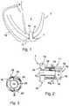
- Fig. 1shows a blood pump 1, which is arranged in a left ventricle 2 of a heart 3.
- an inlet 10protrudes through a hole in the apex 4 of the heart, so that blood is supplied through the inlet 10 of the blood pump 1 and through the proximal outlet 11 via a graft or cannula 12 to another vessel, such as an aorta 5, supplied can be.
- the blood pump 1 in the present embodimentis arranged in the left ventricle 2 and thus forms an LVAD (left VAD), can in other embodiments they may also be designed as RVAD (right VAD) or in combination with another blood pump as BiVAD (biventricular assist device).
- the blood pump 1comprises further elements, which are not shown here for the sake of simplicity.
- the blood pumpcomprises a control unit, which may be arranged in the pump housing or outside the human or animal body.
- the blood pumpis connected to a power supply system so that the pump is provided with sufficient energy for operation.
- the blood pumpmay comprise a "drive line" via which control signals from the pump to the extracorporeal control unit or the power supply from the extracorporeal supply unit to the blood pump 1 can be guided.
- the blood pump 1may include electronics in its housing.
- sensor datawhich are present as analog signals can be digitized and thus supplied to the control unit.
- Fig. 2is the exemplary blood pump 1 of the Fig. 1 shown in a longitudinal section.
- the blood pump 1comprises a distal inlet 10 and a proximal outlet 11. Between the inlet 10 and the outlet 11 extends a cavity 12 which extends between a distal cylindrical portion 13 and a spiral outlet 14 in the region of the outlet 11. In the spiral outlet 14 and the distal portion 13 protrudes a mandrel 15 from the proximal end to the distal end.
- the mandrelis designed such that between a inner wall 16 of the distal portion of the housing 17 and the mandrel 15, a sufficiently large gap remains in order to attach a rotor 18 to the mandrel 15 can.
- the rotor 18includes a distal portion 19 with a blading 20. Furthermore, a proximal portion 21 is shown, which adjoins the distal portion 19. The proximal portion 21, which projects into the spiral chamber 14, has no blading, so that the blading 20 ends distal to the proximal outlet 11 and distal to the spiral chamber 14.
- a stator for setting the rotor in a rotational movement within a cavity 12arranged.
- the stator 22rotates the rotor 18 and is disposed in a gap or cavity of the housing.
- a radial gap 23which is such that a blood film is formed in this gap as soon as the rotor is set in motion and the rotor 18 is stored on this blood film.
- the radial gap 23forms a hydrodynamic bearing.
- the blood flow direction within the gap 23is in opposite directions in some embodiments of the conveying direction of the blood through the pump.
- a gapwhich forms no hydrodynamic bearing in some embodiments.
- the mandrel 15protrudes into the distal portion 13 of the blood pump 1. At its distal end, the mandrel 15 is made flat in the present example. In other embodiments, the mandrel may be rounded or flared at its distal end. This can reduce the flow resistance of the blood.
- Fig. 3is a cross section through the blood pump 1 of Fig. 2 shown. In cross section, the cylindrical shape of the mandrel 15 is clearly visible. Between the rotor 18, in particular an inner surface of the rotor 18 and an outer surface of the mandrel 15, there is the radial gap 23, which is dimensioned such that upon rotation of the rotor 18, a blood film is formed in the gap between the two surfaces forms a hydrodynamic bearing.
- a blading 20 and a further blading 20 'extendsFrom the rotor 18, a blading 20 and a further blading 20 'extends.
- the outer circumference of the rotoris arranged in a cavity 24 of the stator 22, which sets the rotor 18 in rotation. Alternatively to an arrangement of the stator 22 in a cavity 24 of the housing, the stator can be arranged in some embodiments, also within the mandrel.
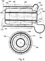
- FIG. 12shows a cross section through a blood pump 100 that includes a distal inlet 101 and a proximal outlet 102.
- the proximal outlet 102is the end of a spiral chamber which enlarges in cross-section and which runs helically. This can be seen for example on the basis of the smaller cross section 103.
- a mandrel 104extends from the proximal end to the distal inlet.
- a cylindrical cavitywhich is interrupted only by the mandrel 104.
- a housing 105Surrounding the cavity, a housing 105 is disposed with a stator 106 in the housing. Placed on the mandrel 104 is a rotor 107.
- the rotorincludes a distal portion 108 with a coil 109.
- the rotor 107includes a proximal portion 110 which has no blading and which begins distally of the spiral outlet and extends to extends to the proximal end of the rotor. So that the rotor can be set in rotation, this comprises permanent magnets 111, which are radially magnetized. Distinguished from this, the rotor comprises further permanent magnets 112, which have an axial magnetization.
- axially magnetized permanent magnet 112axially oriented permanent magnets 113 are arranged in the mandrel 104, which form in conjunction with the permanent magnet 112 a passive magnetic thrust bearing.
- the magnetization of the permanent magnets 112is aligned against the magnetization of the permanent magnets 113.
- the permanent magnets 112 and 113may be formed as ring magnets.
- the permanent magnets 112may be cylindrical sleeves, the upper end of which forms a pole and the lower end of which forms the opposite pole of the magnet.
- the blood pump 100does not include active bearings, but only passive bearings.
- the blading 109 of the rotor 107has no magnetization.
- a ring(magnetized or unmagnetised) radially outside the blading, which serves as an attenuator between an outer side of the ring and an inner side of the housing or the cylindrical cavity and / or as part of the axial, passive bearing
- the ring secured to and circulating the bladingmay be sized to form a hydrodynamic bearing between the ring and an inner wall of the inlet. Only from a correspondingly small gap width outweigh the bearing forces, d. h., This construction alone can radially support the rotating rotor. For larger gap widths, the load capacities are not sufficient, and there must be more bearings, such as magnetic bearings, to support the rotor radially.
- FIG. 5Another blood pump 200 is in the Fig. 5 shown. This also includes a distal inlet 201 and a proximal outlet 202.
- the proximal outlet 202has an expanded cross-sectional area compared to the beginning of the spiral chamber 203.
- the mandrel 204substantially corresponds to the mandrel 104 of the blood pump 100. This also applies to the housing 205 and arranged in the cavity 206 stator.
- the rotor 207is different from the rotor 107. Also, that rotor 207 is configured such that the blading 208 is located only in the distal portion 209, which is distal to the proximal outlet 202.
- the proximal end 210 of the rotoris not provided with a blading.
- the rotorcomprises permanent magnets 211, which are located in the blading 208.
- the rotor 207includes axially magnetized permanent magnets 212, which in cooperation with the also axially, but oppositely magnetized permanent magnet 213 of the mandrel 204 form a passive magnetic thrust bearing.
- the fluid conveyed by the rotortries to push the rotor in the distal direction.
- the orientation of the permanent magnets 212 and 213, respectively,ensures that the rotor is held in its initial position.
- the blading of the blood pump 200the blading of the blood pump, which in the US 2010/0069847 A1 is disclosed.
- the rotor according to this applicationshould have a cavity inside to be able to be placed on the mandrel can.
- the embodiments of the blood pump of FIGS. 4 and 5essentially show a cylindrical mandrel, on which a cylindrical sleeve-shaped rotor is arranged, on the outside of which a blading is again arranged.
- the blood pump 300includes a distal inlet 301 and a proximal outlet 302.
- the proximal outlet 302in contrast to the scroll chamber 303, has an enlarged cross section.
- a mandrel 304extends, which comprises an annular recess 305, in which a rotor 306 is arranged.
- the mandrel 304can be constructed, for example, from a distal portion 307 and a proximal portion 308, wherein the distal portion 307 extends substantially to the annular recess 305.
- the distal portion 307can be screwed on, for example, only when the rotor 306 has been inserted into the annular recess 305.
- stator components 309 and 310are arranged, which can put the rotor in rotation.
- the rotorcomprises permanent magnets 311, which are aligned so that they can be acted upon by the stator with a force.
- the blood pump 300includes further permanent magnets 312 and 313, which are axially aligned and in interaction form a passive axial magnetic bearing.
- the gapforms a hydrodynamic sliding bearing.
- the rotorcan do this be such that the cylinder sleeve shape extends substantially radially to the radial periphery of the mandrel outside the annular recess.
- the blading 315extends into the inner space 318 extending between the housing inner wall 316 and the radial outer diameter 317 of the mandrel.
- the gaps 319 and 320may be dimensioned to also form an axial hydrodynamic journal bearing.
- the permanent magnets 312 and 313may be omitted.
- the axial position of the rotor 306can also be controlled by means of an active axial bearing. Since the blading 315 is located radially outward of the recess, the fluid can be effectively conveyed in the gap 318.
- the blood pump 400includes a distal inlet 401 and a proximal outlet 402.
- the proximal outlet 402is connected to the scroll chamber 403 and has an enlarged cross section in this embodiment.
- a spike 404extends, which comprises a distal portion 405 and a proximal portion 406, which are coupled together via a shoulder 407.
- the shoulder 407may also be referred to as a step.
- the housing wall 408 of the blood pump 400widens in the area of the rotor 409 from the distal inlet to the proximal outlet.
- the mandrel 404is substantially cylindrical in shape, the radially outer circumference of the rotor has a radial expansion 410.
- the expansionis such that the largest pitch of the expansion lies at the distal end 411 of the rotor 409 and the smallest Curvature of the rotor 409 at the proximal end 412 is located. It can be clearly seen that the proximal end of the rotor rests against the shoulder 407.
- the outer circumference of the rotor 409 at the proximal end 412viewed without the blading 413, substantially coincides with the radial extent of the proximal portion 406 of the mandrel 404.
- the bladingcan be, for example, a helix or another blading known from the prior art for VADs, as described, for example, in the exemplary embodiments of FIGS FIGS. 4 or 5 has been described.
- the most distal point of the mandrel 404is formed as a spherical segment surface. This is to improve the flow of blood around the spine.
- a stator 414In the proximal portion 406 of the mandrel 404 is a stator 414 which is configured to interact with the permanent magnets 415 of the rotor 409 and thus enable the rotor to rotate.
- the axial bearingcan be effected for example by means of a combination of axially magnetized permanent magnets 416 and 417.
- the housing wall 408acts in some embodiments as part of a hydrodynamic bearing. This essentially depends on the surface of the blading opposite the housing wall and the distance of the blading from the housing wall. If the rotor 409 is moved in the distal direction, there is a risk that the blading 413 abuts the housing wall 408 in the distal direction. Especially with a helix as a blading, it is to be assumed that the hydrodynamic forces between the helical blading and the housing wall are insufficient to prevent an abutment. As a result, the permanent magnets 416 and 417 act as the sole axial bearing. Radial bearing is caused by the gap 418 between the mandrel 404 and the rotor 409. The same applies to the gap between the rotor 409 and the shoulder 407, which is fluidically connected to the gap 418.
- Blade 413extends the entire length of the rotor viewed from the distal to proximal direction.
- FIG. 2shows a blood pump 500, which essentially corresponds to the blood pump 400 of FIG Fig. 7 equivalent.
- the blood pump 500also has a distal inlet 501 and a proximal outlet 502. Further, a mandrel 504 with a shoulder 507 is provided.
- the rotor 509is, unlike in the embodiment of Fig. 7 , not provided over its entire length with a blading 513. Thus, the blading 513 begins at a distance from the distal start of the rotor 509. Also in the embodiment of the Fig. 8 For example, the rotor 509 is such that the curvature of the radially outer surfaces decreases from the distal inlet to the proximal outlet.
- a stator 514rotates the rotor using permanent magnets. Furthermore, there is an axial bearing, which substantially the axial bearing of Fig. 7 equivalent. Mandrel 504 is flattened at its distal end. The rotor terminates flush with the upstream end of the mandrel 504.
Landscapes
- Health & Medical Sciences (AREA)
- Heart & Thoracic Surgery (AREA)
- Engineering & Computer Science (AREA)
- Cardiology (AREA)
- Life Sciences & Earth Sciences (AREA)
- Public Health (AREA)
- Biomedical Technology (AREA)
- Hematology (AREA)
- Mechanical Engineering (AREA)
- Animal Behavior & Ethology (AREA)
- General Health & Medical Sciences (AREA)
- Anesthesiology (AREA)
- Veterinary Medicine (AREA)
- Physics & Mathematics (AREA)
- Fluid Mechanics (AREA)
- Vascular Medicine (AREA)
- External Artificial Organs (AREA)
- Structures Of Non-Positive Displacement Pumps (AREA)
Abstract
Translated fromGermanDescription
Translated fromGermanGegenstand der vorliegenden Anmeldung ist eine Blutpumpe gemäß dem Oberbegriff des Anspruchs 1.The subject of the present application is a blood pump according to the preamble of
Blutpumpen, beispielsweise zur Unterstützung eines Herzens, werden beispielsweise bei Patienten mit Herz- oder Gefäßschwächen eingesetzt. Die in dieser Anmeldung beschriebenen Blutpumpen können beispielsweise als Ventricular Assist Devices (VADs) zur Unterstützung des linken Ventrikels, des rechten Ventrikels oder in einem System mit zwei Pumpen für beide Ventrikel eingesetzt werden.Blood pumps, for example, to support a heart, are used for example in patients with cardiac or vascular weaknesses. For example, the blood pumps described in this application can be used as ventricular assist devices (VADs) to support the left ventricle, the right ventricle, or in a two pump system for both ventricles.
Beispielsweise beschreibt die
Eine weitere Blutpumpe ist in der
Aufgabe des Gegenstandes der vorliegenden Anmeldung ist es, eine Blutpumpe zur Verfügung zu stellen, welche einfacher aufgebaut ist und mit welcher Blut bei geringer Blutschädigung gefördert werden kann.Object of the subject of the present application is to provide a blood pump available, which is simpler and with which blood can be promoted at low blood damage.
Erfindungsgemäß wird die Aufgabe durch eine Blutpumpe beispielsweise gemäß Anspruch 1 gelöst.According to the invention the object is achieved by a blood pump, for example according to
Die Blutpumpe umfasst dabei ein Gehäuse mit einem stromaufwärts gelegenen (im Folgenden auch: distalen) Einlass sowie einem stromabwärts gelegenen (im Folgenden auch: proximalen) Auslass und einem zwischen dem Einlass und dem Auslass angeordneten Dorn. Der Dorn erstreckt sich dabei vom stromabwärts gelegenen Ende der Pumpe stromaufwärts im Inneren des Gehäuses zwischen dem stromaufwärts gelegenen Einlass und dem stromabwärts gelegenen Auslass. Koaxial ist auf dem Dorn ein Rotor mit einer Achse und einer Beschaufelung drehend angeordnet, wobei der Rotor auf dem Dorn in einer axialen Richtung magnetisch gelagert ist. Bei den nachfolgend verwendeten Begriffen distal und proximal wird keine Einschränkung hinsichtlich der Einbaulage der Pumpe gemacht, sondern lediglich eine Aussage zu der Anordnung einzelner Komponenten zueinander gemacht.The blood pump in this case comprises a housing with an upstream (also referred to as: distal) inlet and a downstream (also referred to as: proximal) outlet and a mandrel arranged between the inlet and the outlet. The mandrel extends from the downstream end of the pump upstream in the interior of the housing between the upstream inlet and the downstream outlet. Coaxially disposed on the mandrel is a rotor having an axis and a blading in rotation, the rotor being magnetically supported on the mandrel in an axial direction. In the terms distal and proximal used below, no restriction is made with regard to the installation position of the pump, but only a statement made to the arrangement of individual components to each other.
Der Auslass ist dabei stromabwärts eines stromabwärts gelegenen Endes der Beschaufelung angeordnet, bzw. der Rotor ist derart im Gehäuse angeordnet, dass eine Beschaufelung stromaufwärts des stromabwärts gelegenen Auslasses endet.The outlet is arranged downstream of a downstream end of the blading, or the rotor is arranged in the housing such that a blading ends upstream of the downstream outlet.
Eine Blutpumpe mit solchen Merkmalen ist also derart beschaffen, dass zunächst der Rotor das Blut zwischen dem Einlass und proximalen Auslass mit einer axialen Komponente fördert, wobei die Beschaufelung proximal des Auslasses endet. Anschließend wird das Blut durch das nachströmende geförderte Blut in Richtung des Auslasses und durch den Auslass der Pumpe in Richtung eines (Blut-)Gefäßes gepumpt.Thus, a blood pump having such features is such that first the rotor delivers the blood between the inlet and proximal outlet with an axial component, with the blading ending proximal to the outlet. Subsequently, the blood is pumped by the inflowing conveyed blood towards the outlet and through the outlet of the pump in the direction of a (blood) vessel.
Dadurch, dass der Rotor auf dem Dorn in der axialen Richtung magnetisch gelagert ist, kann je nach Einsatzgebiet der Pumpe ein aktives Lager oder ein passives Lager axial ausgebildet werden. Bei einem axialen, passiven magnetischen Lager werden Permanentmagnete sowohl im Rotor als auch im Pumpengehäuse bzw. im Dorn angeordnet und derart zueinander ausgerichtet, dass eine Bewegung des Rotors in Richtung des distalen Pulpeneinlasses aufgrund steigender Magnetkräfte bei einer Bewegung des Rotors in distaler Richtung verhindert wird. Beispielsweise können die Permanentmagnete eine Magnetisierung parallel zur Achse des Dornes aufweisen.Characterized in that the rotor is magnetically supported on the mandrel in the axial direction, depending on the application of the pump, an active bearing or a passive bearing can be formed axially. In an axial, passive magnetic bearing, permanent magnets are disposed both in the rotor and the pump housing or in the mandrel and aligned with one another such that movement of the rotor in the direction of the distal pulp inlet due to increasing magnetic forces during a movement of the rotor in the distal direction is prevented. For example, the permanent magnets may have a magnetization parallel to the axis of the mandrel.
Bei der Verwendung eines aktiven axialen magnetischen Lagers interagieren Permanentmagnete des Rotors mit einer Steuerspule. Ein Stromfluss durch die Steuerspule verändert das magnetische Feld und kann die Permanentmagnete des Rotors anziehen oder abstoßen. Die Position des Rotors wird beispielsweise mit Hilfe einer Sensorspule ermittelt und ein etwaiger Sollabstand bzw. eine etwaige Sollposition des Rotors (in Abhängigkeit vom Arbeitspunkt der Pumpe) durch Beaufschlagung der Steuerspule mit einem entsprechenden Strom hergestellt. Magnetische Lager haben sich als besonders wartungsarm herausgestellt.When using an active axial magnetic bearing, permanent magnets of the rotor interact with a control coil. A current flow through the control coil changes the magnetic field and can attract or repel the permanent magnets of the rotor. The position of the rotor is determined, for example with the aid of a sensor coil and any desired distance or any desired position of the rotor (depending on the operating point of the pump) produced by applying the control coil with a corresponding current. Magnetic bearings have proven to be particularly low maintenance.
Der Dorn kann eine Funktion der radialen Lagerung des Rotors übernehmen. So verhindert der Dorn beispielsweise, dass in radialer Richtung beliebige Positionen durch den Rotor innerhalb des Gehäuses eingenommen werden können. Zudem kann der Dorn in einigen Ausführungsbeispielen Komponenten eines Stators zum Antrieb des Rotors enthalten. Zusätzlich oder alternativ können im Dorn Permanentmagnete, beispielsweise in Form von Magnetringen, angeordnet sein, welche einen Teil der magnetischen, axialen Lagerung bilden. In anderen Ausführungsbeispielen können beispielsweise Elemente des Stators, welche den Rotor in Drehung versetzen, auch innerhalb des Gehäuses angeordnet werden, so dass diese Stator-Komponenten den Rotor radial umgeben. Hinsichtlich des Dorns, des Einlasses und des Auslasses wird beispielsweise auf die Druckschrift
Weitere Ausführungsbeispiele werden nachfolgend und in den Figuren beschrieben.Further exemplary embodiments are described below and in the figures.
In einer Ausführungsform ist der Auslass vollständig proximal eines proximalen Endes der Beschaufelung angeordnet. Dies ist so zu verstehen, dass zwischen dem proximalen Ende der Beschaufelung des Rotors und dem distalen Beginn des Auslasses ein von null verschiedener, positiver Abstand besteht. Ausgehend von den Pumpenparametern, der Drehzahl, Rotorgröße, Beschaufelungsgröße und Ähnlichem, kann der Abstand so bestimmt werden, dass die Blutschädigung minimiert wird. In einigen Ausführungsbeispielen ist der Abstand zwischen dem Auslass und der Beschaufelung größer als 0,05 mm, vorzugsweise größer als 0,1 mm, 0,5 mm, 1 mm bzw. 3 mm, und kleiner als 10 mm, vorzugsweise kleiner als 5 mm. Bezüglich der Bestimmung des Abstandes zwischen dem proximalen Ende der Beschaufelung und dem proximalen Auslass kann der Abstand in einigen Ausführungsbeispielen zwischen dem distalsten Punkt des proximalen Auslasses, projiziert auf die Achse des Dorns bzw. Rotors, und dem proximalen Ende der Beschaufelung, projiziert auf die Achse des Dorns bzw. Rotors, gemessen werden. In anderen Ausführungsbeispielen kann der Abstand zwischen einem distalsten Punkt einer Spiralkammer und dem proximalen Ende der Beschaufelung, jeweils projiziert auf die Achse des Dorns bzw. Rotors, gemessen werden. Unter einer Spiralkammer bzw. Tangentialkammer kann hierbei ein Bereich des Gehäuses verstanden werden, welcher sich an einen beispielsweise zylinderförmigen Grundkörper anschließt und welcher derart geformt ist (beispielsweise als Schneckenform), dass dem Blut aufgrund der Gehäusegeometrie eine Tangentialkomponente der Strömungsgeschwindigkeit aufgezwungen wird. Dabei kann der Übergang vom Grundkörper zur Volute stetig oder sprunghaft verlaufen, in dem Sinne, dass ein Durchmesser des Grundkörpers sich stetig oder sprunghaft zu einem größeren Durchmesser der Spiralkammer aufweitet.In one embodiment, the outlet is located entirely proximate a proximal end of the blading. This is to be understood as meaning that there is a non-zero, positive distance between the proximal end of the blading of the rotor and the distal beginning of the outlet. Based on the pump parameters, speed, rotor size, blading size and the like, the distance can be determined to minimize blood damage. In some embodiments, the distance between the outlet and the blading is greater than 0.05 mm, preferably greater than 0.1 mm, 0.5 mm, 1 mm or 3 mm, and less than 10 mm, preferably less than 5 mm , Regarding the determination of the distance between the proximal end of the blading and the proximal outlet, in some embodiments, the distance may be projected between the most distal point of the proximal outlet projected onto the axis of the mandrel and the proximal end of the blading projected onto the axis of the mandrel or rotor, are measured. In other embodiments, the distance between a most distal point of a coil chamber and the proximal end of the blading, each projected onto the axis of the mandrel or rotor, can be measured. In this case, a spiral chamber or tangential chamber can be understood to mean a region of the housing which adjoins an, for example, cylindrical base body and which is shaped in such a way (for example as a screw shape) that a tangential component of the flow velocity is imposed on the blood due to the housing geometry. The transition from the main body to the volute can be continuous or erratic, in the sense that a diameter of the body is continuous or abruptly widens to a larger diameter of the spiral chamber.
In einer besonders bevorzugten Variante ist der Auslass gegenüber der Achse des Rotors um einen Winkel von mehr als 45°, vorzugsweise zwischen 80° und 100°, geneigt. Insbesondere kann der Auslass ein Spiralgehäuse (oder auch: Volute) umfassen, dessen Auslassrichtung im Wesentlichen um 90° von der Achse des Rotors abweicht. Der Auslass kann dabei beispielsweise als ein Spiralgehäuse ausgebildet sein, wie dies beispielsweise in der
In einer weiteren Ausführungsform umfasst der Rotor eine Hülse, insbesondere eine Zylinderhülse, wobei die Beschaufelung entlang eines äußeren Umfangs der Hülse angeordnet ist. Die Zylinderhülsenform des Rotors hat die Vorteile, dass ebenfalls ein zylinderförmiger Dorn verwendet werden kann. Sowohl die Zylinderhülse als auch ein zylinderförmiger Dorn haben den Vorteil, dass diese Geometrie vergleichsweise einfach herzustellen ist und somit die Pumpen kostengünstig herstellbar sind. Zudem hat sich gezeigt, dass die Auslegung der Lagerung des Motors durch die Zylinderhülse vereinfacht wird. Eine Zylinderhülse bietet auch die Möglichkeit, einen Hohlraum zwischen einer Zylinderinnenwand und einer Zylinderaußenwand zu bilden, in welchem beispielsweise Permanentmagnete für ein axiales Magnetlager angeordnet werden können oder sind.In a further embodiment, the rotor comprises a sleeve, in particular a cylinder sleeve, wherein the blading is arranged along an outer circumference of the sleeve. The cylinder sleeve shape of the rotor has the advantages that a cylindrical mandrel can also be used. Both the cylinder sleeve and a cylindrical mandrel have the advantage that this geometry is relatively easy to manufacture and thus the pumps are inexpensive to produce. In addition, it has been shown that the design of the bearing of the engine is simplified by the cylinder sleeve. A cylinder sleeve also offers the possibility of forming a cavity between a cylinder inner wall and a cylinder outer wall, in which, for example, permanent magnets for an axial magnetic bearing can be arranged or are.
In einer weiteren Ausführungsform befindet sich zwischen der Hülse und dem Dorn ein hydrodynamisches Lager. Dabei ist der Spalt zwischen der Oberfläche des Dorns und einem inneren Umfang des Rotors bzw. der Hülse bzw. der Zylinderhülse derart bemessen und ausgestaltet, dass den Spalt durchströmendes Blut den Rotor radial stabilisiert und somit ein radiales Lager bildet. Dabei kann das radiale Lager beispielsweise zwischen zwei im Wesentlichen parallelen Oberflächen des Rotors bzw. des Dorns ausgebildet sein, deren Abstand derart gewählt ist, dass das hindurchströmende Blut eine Gleitfläche bildet. In anderen Varianten kann entweder die Oberfläche des Dorns und/oder die Innenfläche des Rotors mit Kanälen oder ähnlichen Strukturen beaufschlagt sein, um das hydrodynamische Lager auszubilden.In a further embodiment, there is a hydrodynamic bearing between the sleeve and the mandrel. In this case, the gap between the surface of the mandrel and an inner circumference of the rotor or the sleeve or the cylinder sleeve is dimensioned and designed such that blood flowing through the gap radially stabilizes the rotor and thus forms a radial bearing. In this case, the radial bearing may for example be formed between two substantially parallel surfaces of the rotor or of the mandrel whose spacing is selected such that the blood flowing through forms a sliding surface. In other variants, either the surface of the mandrel and / or the inner surface of the rotor with channels or similar structures may be applied to form the hydrodynamic bearing.
Hinsichtlich der hydrodynamischen Lagerung wird beispielsweise auf die
In einer weiteren Ausführungsform ist die Beschaufelung als eine Wendel ausgebildet, Unter einer Wendel wird hierbei eine helixartige Struktur verstanden, welche beispielsweise auf einem Zylindermantel abgewickelt ist. Dabei kann der Rotor lediglich eine Wendel oder mehrere Wendeln umfassen. In zahlreichen Ausführungsbeispielen besitzt die Wendel dabei eine im Querschnitt betrachtete Breite, welche deutlich kleiner ist als der Abstand zweier Wendeln auf der Rotoroberfläche. Ein Beispiel einer Beschaufelung ist beispielsweise die archimedische Schraube. Dies bedeutet, dass die Breite der Flächen, durch welche das Blut gefördert wird, größer ist als die Breite der Wendel. Die Flüssigkeit wird quasi in Richtung des Auslasses "geschraubt". Hinsichtlich der Wendel wird ebenfalls auf die
In einer weiteren Ausführungsform ist der Rotor derart ausgebildet, dass ein proximales Ende des Rotors proximal des proximalen Endes der Beschaufelung des Rotors liegt. In anderen Worten erstreckt sich der Rotor in proximaler Richtung weiter als die Beschaufelung. Es existiert also ein proximaler Abschnitt des Rotors, welcher nicht mit einer Beschaufelung versehen ist, Ein derartiger Rotor ermöglicht beispielsweise eine sehr einfache Ausgestaltung des Dorns. Der Dorn muss hierbei keinerlei Strukturierungen aufweisen.In another embodiment, the rotor is configured such that a proximal end of the rotor is proximal to the proximal end of the blading of the rotor. In other words, the rotor extends in the proximal direction further than the blading. Thus, there is a proximal portion of the rotor, which is not provided with a blading, Such a rotor allows, for example, a very simple embodiment of the mandrel. The mandrel must have no structuring here.
In weiteren Ausführungsformen umfasst der Dorn einen ersten distalen Abschnitt zur Aufnahme des Rotors und einen zweiten, proximal des ersten Abschnitts gelegenen Abschnitt, wobei zwischen dem ersten und zweiten Abschnitt eine Schulter einen Anschlag für ein proximales Ende des Rotors bildet. In dieser Ausführungsform kann der Rotor bis zu seinem proximalen Ende hin mit einer Beschaufelung versehen sein. Aufgrund der Schulter, welche distal des proximalen Auslasses liegt, endet auch die Beschaufelung des Rotors distal des proximalen Auslasses. Durch die Schulter wird zum einen ein mechanischer Anschlag des Rotors ausgebildet, und ferner kann im Betrieb der Pumpe zwischen der Schulter und dem Rotor ein hydrodynamischer Druck aufgebaut werden, welcher ein Anschlagen des Rotors an der Schulter verhindert.In further embodiments, the spine includes a first distal portion for receiving the rotor and a second portion proximal the first portion, wherein between the first and second portions a shoulder forms a stop for a proximal end of the rotor. In this embodiment, the rotor may be provided with a blading up to its proximal end. Due to the shoulder distal to the proximal outlet, the blading of the rotor also terminates distal to the proximal outlet. Through the shoulder, on the one hand, a mechanical stop of the rotor is formed, and further, a hydrodynamic pressure can be built up between the shoulder and the rotor during operation of the pump, which prevents the rotor from striking the shoulder.
In einer weiteren Ausführungsform besitzt der Dorn eine im Wesentlichen ringförmige Ausnehmung, in welcher der Rotor drehbar gelagert ist. Dies hat beispielsweise den Vorteil, dass der Rotor mechanisch in axialer Richtung nicht ausbrechen kann. Nachteilig ist jedoch der erschwerte Zusammenbau der Blutpumpe. In einigen Varianten des Vorhandenseins einer ringförmigen Ausnehmung ist die Beschaufelung des Rotors radial außerhalb der Ausnehmung angeordnet.In a further embodiment, the mandrel has a substantially annular recess in which the rotor is rotatably mounted. This has the advantage, for example, that the rotor can not mechanically break out in the axial direction. The disadvantage, however, is the complicated assembly of the blood pump. In some variations of the presence of an annular recess, the blading of the rotor is located radially outwardly of the recess.
Der Gegenstand der Anmeldung soll anhand der in den Figuren beschriebenen Elemente näher beschrieben werden. Es zeigen
- Fig. 1
- eine Darstellung einer Verwendung einer Blutpumpe als VAD;
- Fig. 2
- eine schematische Darstellung einer Blutpumpe im Längsschnitt;
- Fig. 3
- eine schematische Darstellung der Blutpumpe der
Fig. 2 im Querschnitt; - Fig. 4 und Fig. 5
- Ausführungsformen einer Blutpumpe gemäß der Anmeldung mit zylinderförmigem Dorn;
- Fig. 6
- einen Längsschnitt einer Ausführungsform einer Blutpumpe mit einer ringförmigen Ausnehmung;
- Fig. 7 und Fig. 8
- Ausführungsformen einer Blutpumpe mit einer an dem Dorn angeordneten Schulter.
- Fig. 1
- a representation of a use of a blood pump as VAD;
- Fig. 2
- a schematic representation of a blood pump in longitudinal section;
- Fig. 3
- a schematic representation of the blood pump of
Fig. 2 in cross-section; - 4 and FIG. 5
- Embodiments of a blood pump according to the application with a cylindrical mandrel;
- Fig. 6
- a longitudinal section of an embodiment of a blood pump with an annular recess;
- FIGS. 7 and 8
- Embodiments of a blood pump with a shoulder disposed on the mandrel.
Die Blutpumpe 1 umfasst weitere Elemente, welche hier zur Vereinfachung nicht dargestellt sind. So umfasst die Blutpumpe beispielsweise eine Kontrolleinheit, welche im Pumpengehäuse oder außerhalb des menschlichen oder tierischen Körpers angeordnet sein kann. Zudem ist die Blutpumpe mit einem Energieversorgungssystem verbunden, so dass die Pumpe mit ausreichender Energie zum Betrieb versehen wird. Weiterhin kann die Blutpumpe eine "Drive-Line" umfassen, über welche Steuersignale von der Pumpe zur extrakorporalen Kontrolleinheit oder die Stromversorgung von der extrakorporalen Versorgungseinheit zur Blutpumpe 1 geführt werden können.The
Obgleich in der vorliegenden Anmeldung nicht näher ausgeführt, kann die Blutpumpe 1 in ihrem Gehäuse Elektronik umfassen. Hiermit können beispielsweise Sensordaten, welche als analoge Signale vorliegen, digitalisiert und so der Kontrolleinheit zugeführt werden.Although not detailed in the present application, the
In der
Zwischen dem Rotor 18 und dem Dorn 15 befindet sich ein radialer Spalt 23, welcher derart beschaffen ist, dass sich in diesem Spalt ein Blutfilm ausbildet, sobald der Rotor in Bewegung versetzt wird, und der Rotor 18 auf diesem Blutfilm gelagert wird. Auf diese Weise bildet der radiale Spalt 23 ein hydrodynamisches Lager. Dabei ist die Blutflussrichtung innerhalb des Spalts 23 in einigen Ausführungsbeispielen der Förderrichtung des Blutes durch die Pumpe gegenläufig.Between the
Zwischen einem radial äußeren Durchmesser des Rotors 18, insbesondere einem radial äußeren Durchmesser der Beschaufelung 20, und der Innenwand 16 des Gehäuses 17 befindet sich ein Spalt, welcher in einigen Ausführungsbeispielen kein hydrodynamisches Lager bildet.Between a radially outer diameter of the
Der Dorn 15 ragt in den distalen Abschnitt 13 der Blutpumpe 1. An seinem distalen Ende ist der Dorn 15 im vorliegenden Beispiel flach ausgeführt. In anderen Ausführungsbeispielen kann der Dorn an seinem distalen Ende gerundet oder sich aufweitend ausgebildet sein. Dies kann den Strömungswiderstand des Blutes verringern. In der
Vom Rotor 18 erstreckt sich eine Beschaufelung 20 und eine weitere Beschaufelung 20'. Die Beschaufelungen 20 und 20' sind jeweils eine Wendel. Diese umlaufen den Rotor 18 in radialer Richtung helixartig bzw. helixförmig. Es ist deutlich zu erkennen, dass die Breite B der Wendel 20' deutlich kleiner ist als der Abstand zwischen den beiden Wendeln 20 und 20'. Den Rotor außen umlaufend ist in einem Hohlraum 24 der Stator 22 angeordnet, welcher den Rotor 18 in Rotation versetzt. Alternativ zu einer Anordnung des Stators 22 in einem Hohlraum 24 des Gehäuses kann der Stator in einigen Ausführungsbeispielen auch innerhalb des Dorns angeordnet sein.From the
Anhand der
Die Permanentmagnete 112 bzw. 113 können als Ringmagnete ausgebildet sein. So können beispielsweise die Permanentmagnete 112 Zylinderhülsen sein, deren oberes Ende einen Pol und deren unteres Ende den entgegengesetzten Pol des Magnets bilden.The
Im Spalt 114 zwischen dem proximalen Ende des Spiralauslasses, dem Dorn und dem Rotor wird bei Rotation des Rotors ein Blutfluss angeregt, welcher als hydrodynamisches Lager wirkt. Somit umfasst die Blutpumpe 100 keine aktiven Lager, sondern lediglich passive Lager. Im vorliegenden Beispiel besitzt die Beschaufelung 109 des Rotors 107 keinerlei Magnetisierung. In einigen Ausführungsbeispielen kann jedoch vorgesehen sein, radial außerhalb der Beschaufelung einen Ring (magnetisiert oder unmagnetisiert) anzuordnen, welcher als Dämpfungsglied zwischen einer Außenseite des Rings und einer Innenseite des Gehäuses bzw. des zylinderförmigen Hohlraums und/oder als Teil des axialen, passiven Lagers dient. In einer weiteren Ausführungsform kann der an der Beschaufelung befestigte und diese umlaufende Ring derart bemessen sein, dass ein hydrodynamisches Lager zwischen dem Ring und einer Innenwand des Einlasses gebildet wird. Erst ab einer entsprechend kleinen Spaltbreite überwiegen die Lagerkräfte, d. h., kann diese Konstruktion alleine den rotierenden Rotor radial lagern. Bei größeren Spaltbreiten reichen die Tragkräfte nicht aus, und es müssen weitere Lager, beispielsweise magnetische Lager, vorhanden sein, um den Rotor radial zu lagern.In the
Eine weitere Blutpumpe 200 ist in der
Bei der Blutpumpe 300 der
Im Dorn 304 sind Stator-Komponenten 309 sowie 310 angeordnet, welche den Rotor in Rotation versetzen können. Hierfür umfasst der Rotor Permanentmagneten 311, die derart ausgerichtet sind, dass sie durch den Stator mit einer Kraft beaufschlagt werden können. Ferner umfasst die Blutpumpe 300 weitere Permanentmagneten 312 sowie 313, welche axial ausgerichtet sind und im Zusammenspiel ein passives axiales Magnetlager bilden. In radialer Richtung ist zwischen einer Innenseite des Rotors und einer Außenseite der ringförmigen Ausnehmung ein Spalt 314 vorhanden, in welchem ein Blutfilm ausgebildet werden kann, sobald der Rotor in Bewegung versetzt wurde. Somit bildet der Spalt ein hydrodynamisches Gleitlager. Der Rotor kann dabei derart beschaffen sein, dass die Zylinderhülsenform im Wesentlichen radial bis zum radialen Umfang des Dorns außerhalb der ringförmigen Ausnehmung reicht. Somit erstreckt sich nur die Beschaufelung 315 in den zwischen der Gehäuseinnenwand 316 und dem radialen Außendurchmesser 317 des Dorns erstreckenden Innenraum 318. Alternativ zu der passiven axialen Magnetlagerung können die Spalte 319 bzw. 320 derart dimensioniert sein, dass diese ebenfalls ein axiales hydrodynamisches Gleitlager ausbilden. In diesem Fall können die Permanentmagneten 312 bzw. 313 entfallen. Alternativ kann die axiale Lage des Rotors 306 auch mittels einer aktiven axialen Lagerung geregelt werden. Da die Beschaufelung 315 radial außerhalb der Ausnehmung angeordnet ist, kann das Fluid effektiv in dem Spalt 318 gefördert werden.In the
Weitere Ausführungsformen sind in den
Die Beschaufelung 413 erstreckt sich über die gesamte Länge des Rotors, von distaler in proximaler Richtung gesehen.
Die
Weitere Ausführungsbeispiele ergeben sich für den Fachmann in naheliegender Weise.Other embodiments will be apparent to one of ordinary skill in the art.
Claims (18)
Translated fromGermanwobei
der Auslass stromabwärts eines stromabwärts gelegenen Endes der Beschaufelung angeordnet ist.A blood pump (1; 100; 200; 300; 400; 500) preferably for assisting a heart, the blood pump comprising a housing having an upstream inlet (11; 101; 201; 301; 401), a downstream outlet (12; 102; 202; 302; 402) and a mandrel (15; 104; 204; 304; 404; 504) disposed between the inlet and the outlet and coaxially on the mandrel a rotor (18; 108; 208; 306; 409; 509) is rotatably disposed with an axis and blading (20; 109; 209; 315; 413; 513), the rotor being magnetically supported on the mandrel in an axial direction,
in which
the outlet is located downstream of a downstream end of the blading.
Priority Applications (5)
| Application Number | Priority Date | Filing Date | Title |
|---|---|---|---|
| EP15184862.9AEP3141271A1 (en) | 2015-09-11 | 2015-09-11 | Blood pump, preferably for assisting a heart |
| US15/758,797US10926012B2 (en) | 2015-09-11 | 2016-09-12 | Blood pump, preferably for assisting a heart |
| PCT/EP2016/071403WO2017042377A1 (en) | 2015-09-11 | 2016-09-12 | Blood pump, preferably for assisting a heart |
| DE112016004122.5TDE112016004122A5 (en) | 2015-09-11 | 2016-09-12 | Blood pump, preferably to support a heart |
| CN201680052109.7ACN108025123A (en) | 2015-09-11 | 2016-09-12 | It is preferably used for the blood pump of accessory heart |
Applications Claiming Priority (1)
| Application Number | Priority Date | Filing Date | Title |
|---|---|---|---|
| EP15184862.9AEP3141271A1 (en) | 2015-09-11 | 2015-09-11 | Blood pump, preferably for assisting a heart |
Publications (1)
| Publication Number | Publication Date |
|---|---|
| EP3141271A1true EP3141271A1 (en) | 2017-03-15 |
Family
ID=54106262
Family Applications (1)
| Application Number | Title | Priority Date | Filing Date |
|---|---|---|---|
| EP15184862.9AWithdrawnEP3141271A1 (en) | 2015-09-11 | 2015-09-11 | Blood pump, preferably for assisting a heart |
Country Status (5)
| Country | Link |
|---|---|
| US (1) | US10926012B2 (en) |
| EP (1) | EP3141271A1 (en) |
| CN (1) | CN108025123A (en) |
| DE (1) | DE112016004122A5 (en) |
| WO (1) | WO2017042377A1 (en) |
Families Citing this family (17)
| Publication number | Priority date | Publication date | Assignee | Title |
|---|---|---|---|---|
| EP4290081A3 (en) | 2015-09-25 | 2024-02-21 | Procyrion, Inc. | Non-occluding intravascular blood pump providing reduced hemolysis |
| CA3066361A1 (en) | 2017-06-07 | 2018-12-13 | Shifamed Holdings, Llc | Intravascular fluid movement devices, systems, and methods of use |
| WO2019094963A1 (en) | 2017-11-13 | 2019-05-16 | Shifamed Holdings, Llc | Intravascular fluid movement devices, systems, and methods of use |
| CN112004563B (en) | 2018-02-01 | 2024-08-06 | 施菲姆德控股有限责任公司 | Intravascular blood pump and methods of use and manufacture |
| DE102018207594A1 (en)* | 2018-05-16 | 2019-11-21 | Kardion Gmbh | Rotor, magnetic coupling device, electric motor for a cardiac assist system, pump unit for a cardiac assist system and method for manufacturing a rotor |
| US12161857B2 (en) | 2018-07-31 | 2024-12-10 | Shifamed Holdings, Llc | Intravascular blood pumps and methods of use |
| WO2020073047A1 (en) | 2018-10-05 | 2020-04-09 | Shifamed Holdings, Llc | Intravascular blood pumps and methods of use |
| IT201900011640A1 (en) | 2019-07-12 | 2021-01-12 | Salvatore Romano | CARDIAC CHAMBER PROSTHESES AND RELATED CARDIAC CARE SYSTEM |
| WO2021011473A1 (en) | 2019-07-12 | 2021-01-21 | Shifamed Holdings, Llc | Intravascular blood pumps and methods of manufacture and use |
| US11654275B2 (en) | 2019-07-22 | 2023-05-23 | Shifamed Holdings, Llc | Intravascular blood pumps with struts and methods of use and manufacture |
| EP4501393A3 (en) | 2019-09-25 | 2025-04-09 | Shifamed Holdings, LLC | Catheter blood pumps and collapsible pump housings |
| WO2021062265A1 (en) | 2019-09-25 | 2021-04-01 | Shifamed Holdings, Llc | Intravascular blood pump systems and methods of use and control thereof |
| US12121713B2 (en) | 2019-09-25 | 2024-10-22 | Shifamed Holdings, Llc | Catheter blood pumps and collapsible blood conduits |
| IL293625A (en) | 2019-12-03 | 2022-08-01 | Procyrion Inc | blood pumps |
| EP4072650A4 (en) | 2019-12-11 | 2024-01-10 | Shifamed Holdings, LLC | Descending aorta and vena cava blood pumps |
| WO2021119413A1 (en) | 2019-12-13 | 2021-06-17 | Procyrion, Inc. | Support structures for intravascular blood pumps |
| CN110743051B (en) | 2019-12-24 | 2020-05-15 | 丰凯医疗器械(上海)有限公司 | Quick-connection type magnetic transmission device for medical interventional instrument |
Citations (8)
| Publication number | Priority date | Publication date | Assignee | Title |
|---|---|---|---|---|
| WO1989007427A1 (en)* | 1988-02-17 | 1989-08-24 | Jarvik Robert K | Artificial heart structure and methods of use |
| US5824070A (en)* | 1995-10-30 | 1998-10-20 | Jarvik; Robert | Hybrid flow blood pump |
| US20060024182A1 (en) | 2004-03-18 | 2006-02-02 | Mustafa Akdis | Pump |
| US20060183962A1 (en)* | 2003-04-30 | 2006-08-17 | Takeshi Okubo | Artificial cardiac pump |
| WO2007105842A1 (en)* | 2006-03-15 | 2007-09-20 | Korea University Industrial & Academic Collaboration Foundation | Rotary blood pump |
| US20100069847A1 (en) | 2005-10-05 | 2010-03-18 | Larose Jeffrey A | Axial Flow-Pump With Multi-Grooved Rotor |
| WO2012150045A2 (en) | 2011-05-05 | 2012-11-08 | Berlin Heart Gmbh | Blood pump |
| US20140322020A1 (en) | 2003-09-18 | 2014-10-30 | Thoratec Corporation | Rotary Blood Pump |
Family Cites Families (4)
| Publication number | Priority date | Publication date | Assignee | Title |
|---|---|---|---|---|
| US5112200A (en)* | 1990-05-29 | 1992-05-12 | Nu-Tech Industries, Inc. | Hydrodynamically suspended rotor axial flow blood pump |
| DE10108810A1 (en) | 2001-02-16 | 2002-08-29 | Berlin Heart Ag | Device for the axial conveyance of liquids |
| DE102006036948A1 (en)* | 2006-08-06 | 2008-02-07 | Akdis, Mustafa, Dipl.-Ing. | blood pump |
| WO2012051454A2 (en)* | 2010-10-13 | 2012-04-19 | Thoratec Corporation | Pumping blood |
- 2015
- 2015-09-11EPEP15184862.9Apatent/EP3141271A1/ennot_activeWithdrawn
- 2016
- 2016-09-12WOPCT/EP2016/071403patent/WO2017042377A1/ennot_activeCeased
- 2016-09-12DEDE112016004122.5Tpatent/DE112016004122A5/enactivePending
- 2016-09-12USUS15/758,797patent/US10926012B2/enactiveActive
- 2016-09-12CNCN201680052109.7Apatent/CN108025123A/enactivePending
Patent Citations (8)
| Publication number | Priority date | Publication date | Assignee | Title |
|---|---|---|---|---|
| WO1989007427A1 (en)* | 1988-02-17 | 1989-08-24 | Jarvik Robert K | Artificial heart structure and methods of use |
| US5824070A (en)* | 1995-10-30 | 1998-10-20 | Jarvik; Robert | Hybrid flow blood pump |
| US20060183962A1 (en)* | 2003-04-30 | 2006-08-17 | Takeshi Okubo | Artificial cardiac pump |
| US20140322020A1 (en) | 2003-09-18 | 2014-10-30 | Thoratec Corporation | Rotary Blood Pump |
| US20060024182A1 (en) | 2004-03-18 | 2006-02-02 | Mustafa Akdis | Pump |
| US20100069847A1 (en) | 2005-10-05 | 2010-03-18 | Larose Jeffrey A | Axial Flow-Pump With Multi-Grooved Rotor |
| WO2007105842A1 (en)* | 2006-03-15 | 2007-09-20 | Korea University Industrial & Academic Collaboration Foundation | Rotary blood pump |
| WO2012150045A2 (en) | 2011-05-05 | 2012-11-08 | Berlin Heart Gmbh | Blood pump |
Also Published As
| Publication number | Publication date |
|---|---|
| WO2017042377A1 (en) | 2017-03-16 |
| US20180303991A1 (en) | 2018-10-25 |
| DE112016004122A5 (en) | 2018-05-24 |
| CN108025123A (en) | 2018-05-11 |
| US10926012B2 (en) | 2021-02-23 |
Similar Documents
| Publication | Publication Date | Title |
|---|---|---|
| EP3141271A1 (en) | Blood pump, preferably for assisting a heart | |
| EP3856276B1 (en) | Sealed micropump | |
| EP3833410B1 (en) | Bearing device for a heart support system, and method for rinsing a space in a bearing device for a heart support system | |
| EP3359215B1 (en) | Pump, in particular blood pump | |
| EP1360416B1 (en) | Device for axially conveying fluids | |
| EP0905379B1 (en) | Centrifugal pump and centrifugal pump arrangement | |
| EP2234658B1 (en) | Catheter device | |
| EP3000493B1 (en) | Catheter device | |
| EP2814534B1 (en) | Intravascular bloodpump | |
| EP0900572B1 (en) | Centrifugal pump | |
| EP2520317B1 (en) | Blood pump | |
| WO2017042378A1 (en) | Blood pump, preferably for supporting a heart | |
| EP2319552A1 (en) | Blood pump | |
| EP1738783A1 (en) | Axial flow pump with helical blade | |
| EP3545983A1 (en) | Blood pump |
Legal Events
| Date | Code | Title | Description |
|---|---|---|---|
| PUAI | Public reference made under article 153(3) epc to a published international application that has entered the european phase | Free format text:ORIGINAL CODE: 0009012 | |
| AK | Designated contracting states | Kind code of ref document:A1 Designated state(s):AL AT BE BG CH CY CZ DE DK EE ES FI FR GB GR HR HU IE IS IT LI LT LU LV MC MK MT NL NO PL PT RO RS SE SI SK SM TR | |
| AX | Request for extension of the european patent | Extension state:BA ME | |
| STAA | Information on the status of an ep patent application or granted ep patent | Free format text:STATUS: THE APPLICATION IS DEEMED TO BE WITHDRAWN | |
| 18D | Application deemed to be withdrawn | Effective date:20170916 |