EP3138511B1 - Surgical fastener applying apparatus with controlled beam deflection - Google Patents
Surgical fastener applying apparatus with controlled beam deflectionDownload PDFInfo
- Publication number
- EP3138511B1 EP3138511B1EP16186780.9AEP16186780AEP3138511B1EP 3138511 B1EP3138511 B1EP 3138511B1EP 16186780 AEP16186780 AEP 16186780AEP 3138511 B1EP3138511 B1EP 3138511B1
- Authority
- EP
- European Patent Office
- Prior art keywords
- deflection
- section
- distal end
- channel member
- anvil half
- Prior art date
- Legal status (The legal status is an assumption and is not a legal conclusion. Google has not performed a legal analysis and makes no representation as to the accuracy of the status listed.)
- Expired - Lifetime
Links
- 230000003014reinforcing effectEffects0.000claimsdescription127
- 230000015572biosynthetic processEffects0.000claimsdescription4
- 230000000284resting effectEffects0.000claimsdescription3
- 230000002787reinforcementEffects0.000description19
- 230000000694effectsEffects0.000description7
- 239000000463materialSubstances0.000description6
- 229910000831SteelInorganic materials0.000description4
- 230000008859changeEffects0.000description4
- 239000010959steelSubstances0.000description4
- RTAQQCXQSZGOHL-UHFFFAOYSA-NTitaniumChemical compound[Ti]RTAQQCXQSZGOHL-UHFFFAOYSA-N0.000description3
- 239000011152fibreglassSubstances0.000description3
- -1for exampleSubstances0.000description3
- 229920000515polycarbonatePolymers0.000description3
- 239000004417polycarbonateSubstances0.000description3
- 229920005989resinPolymers0.000description3
- 239000011347resinSubstances0.000description3
- 229910052719titaniumInorganic materials0.000description3
- 239000010936titaniumSubstances0.000description3
- 238000003466weldingMethods0.000description3
- 238000004026adhesive bondingMethods0.000description2
- 238000005452bendingMethods0.000description2
- 238000010276constructionMethods0.000description2
- 230000003993interactionEffects0.000description2
- 238000000034methodMethods0.000description2
- 230000009467reductionEffects0.000description2
- 229910001220stainless steelInorganic materials0.000description2
- 239000010935stainless steelSubstances0.000description2
- 230000007704transitionEffects0.000description2
- 230000004075alterationEffects0.000description1
- 238000013459approachMethods0.000description1
- 230000003247decreasing effectEffects0.000description1
- 230000009977dual effectEffects0.000description1
- 239000012530fluidSubstances0.000description1
- 238000003780insertionMethods0.000description1
- 230000037431insertionEffects0.000description1
- 238000004519manufacturing processMethods0.000description1
- 238000012986modificationMethods0.000description1
- 230000004048modificationEffects0.000description1
- 238000002360preparation methodMethods0.000description1
- 230000002265preventionEffects0.000description1
- 238000005476solderingMethods0.000description1
Images


Classifications
- A—HUMAN NECESSITIES
- A61—MEDICAL OR VETERINARY SCIENCE; HYGIENE
- A61B—DIAGNOSIS; SURGERY; IDENTIFICATION
- A61B17/00—Surgical instruments, devices or methods
- A61B17/10—Surgical instruments, devices or methods for applying or removing wound clamps, e.g. containing only one clamp or staple; Wound clamp magazines
- A61B17/105—Wound clamp magazines
- A—HUMAN NECESSITIES
- A61—MEDICAL OR VETERINARY SCIENCE; HYGIENE
- A61B—DIAGNOSIS; SURGERY; IDENTIFICATION
- A61B17/00—Surgical instruments, devices or methods
- A61B17/068—Surgical staplers, e.g. containing multiple staples or clamps
- A—HUMAN NECESSITIES
- A61—MEDICAL OR VETERINARY SCIENCE; HYGIENE
- A61B—DIAGNOSIS; SURGERY; IDENTIFICATION
- A61B17/00—Surgical instruments, devices or methods
- A61B17/068—Surgical staplers, e.g. containing multiple staples or clamps
- A61B17/072—Surgical staplers, e.g. containing multiple staples or clamps for applying a row of staples in a single action, e.g. the staples being applied simultaneously
- A61B17/07207—Surgical staplers, e.g. containing multiple staples or clamps for applying a row of staples in a single action, e.g. the staples being applied simultaneously the staples being applied sequentially
- A—HUMAN NECESSITIES
- A61—MEDICAL OR VETERINARY SCIENCE; HYGIENE
- A61B—DIAGNOSIS; SURGERY; IDENTIFICATION
- A61B17/00—Surgical instruments, devices or methods
- A61B17/068—Surgical staplers, e.g. containing multiple staples or clamps
- A61B17/072—Surgical staplers, e.g. containing multiple staples or clamps for applying a row of staples in a single action, e.g. the staples being applied simultaneously
- A61B2017/07214—Stapler heads
- A—HUMAN NECESSITIES
- A61—MEDICAL OR VETERINARY SCIENCE; HYGIENE
- A61B—DIAGNOSIS; SURGERY; IDENTIFICATION
- A61B17/00—Surgical instruments, devices or methods
- A61B17/28—Surgical forceps
- A61B17/29—Forceps for use in minimally invasive surgery
- A61B2017/2926—Details of heads or jaws
Definitions
- the present disclosurerelates to surgical fastener applying apparatus and, more particularly, to surgical fastener applying apparatus that include a deflection control system for controlling and/or reducing the rate of deflection of an anvil beam.
- Surgical fastener applying apparatusfor example, surgical stapling apparatus
- a staple cartridge receiving half-section including a staple cartridge assembly provided at a distal end thereofis operatively connected (e.g., pivotably connected) to an anvil half-section including an anvil provided at a distal end thereof.
- the staple cartridge assemblypreferably includes a plurality of surgical staples which are ejectable therefrom.
- the staple cartridge assemblymay be manufactured as an integral part of the staple cartridge receiving half-section, or the staple cartridge assembly may be designed and manufactured as a disposable loading unit for use in a reusable surgical stapling apparatus.
- the opposing surfaces of the distal end of the staple cartridge assembly and the distal end of the anvil assemblyare spaced apart by a predetermined distance which is pre-established and fixed for each surgical stapling apparatus. This spacing is sometimes referred to as the "tissue gap" of the surgical stapling apparatus.
- the "tissue gap”be substantially uniform and/or “fixed” (i.e., having the same dimension throughout the stapling operation)
- the operator of the surgical stapling apparatusneeds to ascertain whether the "tissue gap” is loaded with more or thicker tissue than recommended (i.e., overloaded) which may result in undesired or increased deflection of the distal end of the anvil half-section and/or the staple cartridge receiving half-section.
- deflectionis understood to include flexing, bending, deforming, biasing, skewing and the like.
- tissue having a thickness larger, preferably slightly larger, than the height of the "tissue gap”be clamped between the tissue contacting surface of the staple cartridge assembly and the anvil so that when the surgical stapling apparatus is clamped onto the tissue, the tissue substantially fills the entire height of the "tissue gap".
- clamping of such tissue between the tissue contacting surfaces of the distal ends of the anvil and staple cartridge receiving half-sectionstends to cause the distal ends of the anvil and/or staple cartridge receiving half-sections to deflect.
- WO03079909discloses a surgical fastener applying apparatus for sequentially applying a plurality of surgical fasteners to body tissue, wherein the apparatus comprises an anvil half-section and a cartridge receiving half-section.
- the apparatuscomprises an anvil half-section and a cartridge receiving half-section.
- at least one vertically oriented longitudinally running reinforcing stripis provided therewithin.
- a surgical stapling apparatusthat includes a deflection control system for controlling and/or reducing the rate and/or degree of deflection of the distal end of the anvil half-section when tissue is clamped between the distal ends of the anvil and staple cartridge receiving half-sections.
- a surgical stapling apparatusthat includes a deflection control system which allows rapid initial deflection of the distal end of the anvil half-section to efficaciously achieve the optimal tissue gap when clamping relatively thin tissue and which thereafter reduces the rate of deflection in relatively thicker tissue to maintain the tissue gap as close as possible to the optimal tissue gap.
- Surgical stapling apparatus constructed in this mannerwould allow for rapid deflection of the distal end of the anvil half-section to a specific value followed by a decrease in the rate of deflection of the same. Accordingly, the distal end of the anvil half-section is able to deflect quickly to the optimal tissue gap in relatively thin tissue and deflect slowly in relatively thicker tissue to remain as close as possible to the optimal tissue gap.
- a surgical fastener applying apparatusincluding an anvil half-section including a distal end and a proximal end defining a longitudinal axis, a cartridge receiving half-section including a distal end, and a deflection control system operatively associated with the anvil half-section.
- the cartridge receiving half-sectionis desirably operatively couplable with the anvil half-section such that the distal end of the anvil half-section is movable into juxtaposed relation to the distal end of the cartridge receiving half-section.
- a tissue gapis defined between the distal end of the anvil half-section and the distal end of the cartridge receiving half-section when the anvil and cartridge half-sections are coupled together.
- the deflection control systemis configured and adapted to reinforce the distal end of the anvil half-section when a force is applied there in a direction transverse to the longitudinal axis.
- the anvil half-sectiondefines a tissue contacting surface. Accordingly, the deflection control system reinforces the distal end of the anvil half-section when a force is applied to the distal end of the anvil half-section in a direction transverse to the longitudinal axis and normal to a plane defined by the tissue contacting surface of the anvil half-section.
- the anvil half-sectionincludes a U-shaped channel member having a pair of side walls interconnected by a base wall.
- the deflection control systemis operatively associated with the channel member.
- the deflection control systemis desirably operatively disposed within the channel member.
- the deflection control systemcan include a U-shaped channel section having a pair of side walls interconnected by a base wall.
- the base wall of the channel section of the deflection control systemis adjacent, more preferably in contact with the base wall of the channel member of the anvil half-section, and the side walls of the channel section are disposed interior of and adjacent the side walls of the channel member.
- each side wall of the pair of side walls of the channel sectionhas a height which is less than a height of a respective one of the pair of side walls of the channel member thereby defining a reveal along each side wall of the pair of side walls of the channel member.
- the relative height of each side wall of the pair of side walls of the channel sectionis uniform along a length thereof, and each side wall of the pair of side walls of the channel section preferably has a uniform thickness along a length thereof.
- At least a proximal end of the channel sectionis fixedly secured to a proximal end of the channel member.
- the deflection control systemcan be a multi-stage system, e.g., a two-stage system, a three-stage system, a four-stage system, etc.
- the deflection control systembegins reducing the rate of deflection of the distal end of the channel member in a second stage of deflection.
- the second stage of deflectiondesirably takes effect when the reveal between the side walls of the channel member and the side walls of the channel section is about zero. Accordingly, the distal end of the channel member and the distal end of the channel section deflect concomitantly.
- the deflection control systemfunctions such that the greater the rate of deflection of the distal end of the channel member, the greater the reduction in the rate at which the distal end of the channel section deflects. It is contemplated that the reveal between the distal end of the channel member and the distal end of the channel section can be zero.
- the deflection control systemcan include a first U-shaped channel section having a pair of side walls interconnected by a base wall, wherein the base wall of the first channel section of the deflection control system is adjacent to or, more preferably in contact with the base wall of the channel member of the anvil half-section, and a second U-shaped channel section having a pair of side walls interconnected by a base wall, wherein the base wall of the second channel section of the deflection control system is adjacent to or, more preferably in contact with the base wall of the first channel section of the deflection control system.
- a distal end of each side wall of the pair of side walls of the first channel sectioncan have a height which is less than a height of a respective side wall of the pair of side walls of the channel member thereby defining a first reveal along each of the pair of side walls of the channel member.
- each side wall of the pair of side walls of the second channel sectioncan have a height which is less than a height of the respective side walls of the pair of side walls of the first channel section thereby defining a second reveal along a distal end of each side wall of the pair of side walls of the second channel section.
- a proximal end of each of the first and second channel sectionscan be operatively fixedly secured to a proximal end the channel member. It is contemplated that the height of the distal end of each side wall of the pair of side walls of the first channel section and the height of a corresponding distal end of each side wall of the pair of side walls of the second channel section are uniform along each of the lengths thereof.
- the deflection control systemis a three-stage system.
- the deflection control systembegins reducing the rate of deflection of the distal end of the channel section in a second stage of deflection, and in a third stage of deflection the deflection control system reduces the rate of deflection of the distal end of the channel member by an additional amount.
- the second stage of deflectionengages when the first reveal between the side walls of the channel member and the side walls of the first channel section is about zero, whereby the distal end of the channel member and the distal end of the first channel section deflect concomitantly.
- the third stage of deflectionengages when the second reveal between the side walls of the first channel section and the side walls of the second channel section is about zero, whereby the distal end of the channel member, the distal end of the first channel section and the distal end of the second channel section deflect concomitantly.
- the deflection control systemincludes a pair of reinforcing ribs each disposed along an inner surface of a respective side wall of the pair of side walls of the channel member.
- Each rib of the pair of reinforcing ribs of the deflection control systemhas a height which is less than the height of the respective side walls of the channel member thereby defining a reveal along each of the pair of side walls of the channel member. It is envisioned that a proximal end of each of the pair of reinforcing ribs is pinned to a portion of the proximal end of the channel member.
- a proximal end of the deflection control systemis fixedly secured to a portion of the proximal end of the channel member and a portion of the distal end of the deflection control system is longitudinally slidingly coupled to the channel member.
- the deflection control systemcan include at least one, preferably a plurality of, reinforcing plate(s) adjacent, preferably in contact with the base wall of the channel member.
- the surgical fastener applying apparatuscan further include a pin member fixedly secured to the base wall of the channel member.
- the distal end of each of the plurality of reinforcing platesis slidingly coupled to the channel member by the pin member extending through a plurality of elongate longitudinally oriented slots formed, one each, in the plurality of respective reinforcing plates.
- the elongate slotspreferably increase in length from the reinforcing plate which is closest to the base wall of the channel member to the reinforcing plate which is furthest from the base wall of the channel member.
- the slots of the plateseach have a proximal edge, and desirably the proximal edges are in registration with one another.
- the pin memberdesirably includes a head secured to an end thereof that is opposite to the base wall. The head engages the reinforcement plates and forces the distal end of each of the reinforcing plates to deflect concomitantly with the distal end of channel member.
- the deflection control systemis a multi-stage system which begins to incrementally reduce the rate of deflection of the distal end of the channel member as a distal end of each elongate slot of each respective reinforcing plate engages the pin member. The deflection control system incrementally reduces the rate at which the distal end of the channel member deflects.
- surgical fastener applying apparatuscan be provided with a pair of juxtaposed shoulders each extending from an inner surface of the side walls of the channel member in a distal end thereof.
- Each reinforcing platecan include an elongate recesses formed along each lateral side thereof and in operative engagement with a respective one of the pair of shoulders.
- the elongate recessespreferably increase in length from the reinforcing plate which is closest to the base wall of the channel member to the reinforcing plate which is furthest from the base wall of the channel member.
- Each of the elongate recesseshas a proximal edge and wherein the proximal edges are in registration with one another.
- Each shoulderpreferably includes a head portion secured to an end thereof, the head portion being configured and dimensioned to force the distal end of each of the reinforcing plates to deflect concomitantly with the distal end of channel member.
- the deflection control systemis a multi-stage system, wherein the deflection control system begins to incrementally reduce the rate of deflection of the distal end of the channel member as a distal end of each elongate recess of each respective reinforcing plate engages a respective shoulder, the deflection control system incrementally reduces the rate at which the distal end of the channel member deflects.
- a deflection control systemfor a surgical fastener applying apparatus that includes an anvil half-section having a channel member and a cartridge receiving half-section operatively couplable to the anvil half-section.
- the deflection control systemincludes an elongate reinforcing assembly having a proximal end operatively engaged with a proximal end of the channel member and a distal end operatively associated with a distal end of the channel member, wherein the reinforcing assembly incrementally reduces deflection of the distal end of the channel member when forces are applied to the distal end of the channel member in a direction transverse to a longitudinal axis of the channel member and normal to a tissue contacting surface of the anvil half-section.
- a surgical fastener applying apparatusincludes an anvil half-section including a distal end and a proximal end defining a longitudinal axis, the anvil half-section including a channel member having pair of juxtaposed side walls interconnected by a base wall, each side wall defining a through hole having a diameter.
- the apparatusfurther includes a cartridge receiving half-section including a distal end, wherein the cartridge receiving half-section is couplable with the anvil half-section such that the distal end of the anvil half-section is movable into juxtaposed relation to the distal end of the cartridge receiving half-section.
- the distal ends of the anvil and cartridge half-sectionscan be pivotable about a pivot axis transverse to the longitudinal axis.
- the surgical fastener applying apparatusfurther includes a deflection control system operatively associated with the anvil half-section for reinforcing the distal end of the anvil half-section when a force is applied to the distal end of the anvil half-section in a direction transverse to the longitudinal axis.
- the deflection control systemmost preferably includes a pair of reinforcing ribs having a distal end and a proximal end. The distal end of each reinforcing rib is fixedly secured to an inner surface of a respective side wall of the pair of side walls of the channel member and the proximal end of each reinforcing rib extends beyond the pivot axis.
- each reinforcing ribdefines a hole in registration with the through hole defined in the side walls of the channel member.
- the holesare desirably positioned proximal of the pivot axis.
- the deflection control systemfurther includes a cam member extending through the holes formed in each side wall of the channel member and each reinforcing rib, the cam having a diameter smaller than the diameter of the through hole formed in each reinforcing rib to thereby define a reveal between each reinforcing rib and the cam member.
- This deflection control systemis a two-stage system. Accordingly, in operation, the deflection control system begins reducing the degree and the rate of deflection of the distal end of the channel member in a second stage of deflection. The second stage of deflection takes effect when the reveal between an upper portion of the hole formed in each reinforcing rib and an upper portion of the cam is zero.
- proximalwill refer to the end of the surgical fastener applying apparatus which is closest to the operator
- distalwill refer to the end of the surgical fastener applying apparatus which is furthest from the operator.
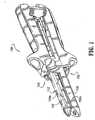
- Apparatus 100is particularly adapted to apply surgical staples and includes a cartridge receiving half-section 102, an anvil half-section 104 operatively coupled to cartridge receiving half-section 102, a staple cartridge assembly 106 fixedly or removably supported in a distal end 102a of cartridge receiving half-section 102 and an anvil plate 108 fixedly or removably supported on a distal end 104a of anvil half-section 104.
- the present disclosuredescribes beam deflection control systems with specific reference to a surgical fastener applying apparatus, preferably a surgical stapler. It is envisioned, however, that the beam deflection control system and illustrative embodiments herein may be incorporated in any surgical fastener applying apparatus having at least one cantilevered beam member which may be subject to deflection under an applied load which has a force component transverse to the longitudinal axis of the beam. It is further envisioned that the beam deflection control system and illustrative embodiments disclosed herein may be incorporated into and/or equally applied to endoscopic, laparoscopic as well as open type surgical instruments.
- the "beam” referred to in “beam deflection control system”can be distal end 102a of cartridge half-section 102, and/or distal end 104a of anvil half-section 104, although most of the discussion herein will refer to the distal end of the anvil half-section because, of the two, typically it is the member which deflects the most.
- tissue gap "G”exists between distal end 104a of anvil half-section 104 and distal end 102a of cartridge receiving half-section 102.
- Tissue gap "G”is typically set to a predetermined dimension during the manufacture of surgical stapling apparatus 100 to allow for desired staple formation.
- tissue gap "G”is tapered, i.e., narrower adjacent a distal end of apparatus 100 than at a location proximal of the distal end of apparatus 100.
- tissue thicknesscan vary, e.g., increase, during approximation and stapling. This can be due, e.g., to tissue fluid flow typically toward the distal tip of the apparatus during approximation of distal ends 104a, 102a of anvil and cartridge receiving half-sections 104, 102, especially those that are pivotably mounted.
- staples(not shown) fired from staple cartridge assembly 106 may form non-uniformly along the length of anvil plate 108.
- the legs of the stapleswill form as intended.
- tissue gap "G"may increase beyond its predetermined setting, e.g., near the distal tip of anvil plate 108, and there is a possibility that in that area the legs of the staples may not form as desired.
- the purpose of this disclosureis to reduce the possibility of or prevent this from occurring.
- the purpose of this disclosureis to increase the possibility that even if excessively thick over-indicated tissue is encountered, deflection will be minimized or prevented, to enhance the possibility of and provide for acceptable staple formation.
- anvil half-section 104includes an anvil half-section channel member 112 having a distal end 112a, a proximal end 112b and a transition or intermediate point 112c.
- Channel member 112has a substantially U-shaped transverse cross-sectional profile defined by a pair of substantially parallel juxtaposed side walls 114 interconnected by a base wall 116.
- Anvil plate 108is preferably configured and dimensioned to fit over side walls 114 of distal end 112a of channel member 112. As seen in FIG. 3 , anvil plate 108 includes a pair of tissue contacting surfaces 118 each having a plurality of staple forming pockets 120 (i.e., anvil pockets, anvil depressions, etc.) formed therein. Preferably, anvil plate 108 includes a knife track 122 extending longitudinally between the pair of tissue contacting surfaces 118. Preferably, knife track 122 interconnects and separates the pair of tissue contacting surfaces 118 from one another. Anvil plate 108 further includes a pair of substantially parallel juxtaposed upstanding side walls 124 extending, one each, from a lateral side edge of the pair of anvil surfaces 118.
- Anvil half-section 104further includes a distal end cap 126 adapted to be snap-fit onto or into the distal tip of channel member 112.
- end cap 126is tapered to facilitate insertion of the distal tip into the target surgical site.
- Anvil half-section 104can also include an end cap 128 to be received between a pair of spaced apart juxtaposed flanges 130 (one shown) extending from proximal end 112b of channel member 112.
- Anvil half-section 104can further include a contoured hand grip 132 configured and adapted to be snap-fit over proximal end 112b of channel member 112.
- Hand grip 132desirably provides an operator of surgical stapling apparatus 100 with improved control and an increased degree of manipulation.
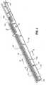
- anvil half-section 104includes a deflection control system, generally designated 140 for reducing the rate of deflection of distal end 112a of channel member 112 as the force in direction "Y" increases and as the deflection distance of distal end 112a of channel member 112 increases.
- deflection control system 140includes a substantially U-shaped channel section 142 disposed between side walls 114 of channel member 112.
- channel section 142is defined by a pair of parallel spaced apart juxtaposed side walls 144 interconnected by a base wall 146.
- side walls 144 of channel section 142preferably have a height which is less than a height of side walls 114 of channel member 112 thus defining a reveal 150 having a height "X".
- Height “X” of reveal 150can be uniform or vary along the entire length of distal end 112a of channel member 112 and distal end 142a of channel section 142. Although, height "X" can taper in either a distal or a proximal direction, preferably it tapers in a distal direction, e.g., from being narrow or zero near the distal tip to a greater height near transition point 112c. Reveal 150 can have discrete regions or lengths, each of which, has a different height "X".
- height "X"is from about 0.004 inches (0.1016 mm) to about 0.10 inches (0.25 cm), more preferably from about 0.004 inches (0.1016 mm) to about 0.006 inches (0.1524 mm).
- height "X"is about 0.004 inches (0.1016 mm) to about 0.006 inches (0.1524 mm)
- distal end 104a of anvil half-section 104becomes stiffer sooner as compared to when height "X" is greater than 0.006 inches (0.1524 mm).
- Channel section 142extends from distal end 112a of channel member 112 to a portion of proximal end 112b.
- Channel section 142is fixedly secured to channel member 112 preferably at least in a region proximal of but adjacent intermediate point 112c to allow channel section 142 to be free to float within channel member 112 in a region distal of intermediate point 112c (i.e., distal end 112a).
- channel section 142can be secured at such locations to channel member 112 at suitable specific predetermined locations along the length thereof.
- side walls 144 of channel section 142can be secured to corresponding side walls 114 of channel member 112, and base wall 146 of channel section 142 can be secured to base wall 116 of channel member 112.
- Channel section 142is preferably secured to channel member 112 by pinning (i.e., by extending a pin through channel section 142 and into an adjacent element or structure of apparatus 100), however, it is envisioned that channel section 142 can be secured to channel member 112 via any number of known techniques, such as, for example, welding, soldering, gluing, peening and the like. Most preferably, channel section 142 is, as will be explained, welded to channel member 112 and a cam 400 can extend through side walls 144 of channel section 142 to pin channel section 142 to side walls 144.
- Channel section 142is made from a rigid material which is resistant to bending, such as, for example, steel. While steel is preferred, it is contemplated that channel section 142 can be fabricated from other materials, such as, for example, titanium, polycarbonate, fiberglass, resins and the like, or any combination thereof.
- each side wall 144 of channel section 142have a preselected thickness.
- a relatively smaller thicknessprovides less rigidity while a relatively larger thickness provides increased rigidity.
- each side wall 144can have a uniform or varying thickness along its length.
- channel section 142increases the rigidity of channel member 112 (i.e., reduces the rate of deflection) after channel member 112 has undergone a predetermined amount of deflection in direction "Y" (e.g., transverse to a longitudinal axis of apparatus 100 and substantially normal to the plane of the tissue contacting surface of anvil 108) thereby reducing the rate of deflection of distal end 112a of channel member 112.
- tissue having a relatively smaller thicknessis understood to mean tissue having a thickness which will not tend to cause distal end 104a of anvil half-section 104 to deflect an amount sufficient to result in the operation of deflection control system 140.
- tissue having a relatively larger thicknessis understood to mean tissue having a thickness which will tend to cause distal end 104a of anvil half-section 104 to deflect an amount sufficient to result in the operation of deflection control system 140.
- Surgical stapling apparatus 100preferably is initially set-up such that tissue gap "G" has a slight taper from a proximal end to a distal end (i.e., tissue gap "G” reduces in height from the proximal end to the distal end).
- tissue gap "G”reduces in height from the proximal end to the distal end.
- channel section 142 of deflection control system 140causes distal end 104a of anvil half-section 104 to undergo a two-stage deflection.
- the deflection forceacts solely on edge surfaces 114a of side walls 114, oriented in the direction of the tissue to be clamped, of channel member 112 resulting in distal end 104a of anvil half-section 104 undergoing an initial rate of deflection in direction "Y", until height "X" of reveal 150, between side walls 144 of channel section 142 and side walls 114 of channel member 112, is reduced to zero (i.e., the height of side walls 144 of channel section 142 are even with the height of side walls 114 of channel member 112).
- Edge surfaces 114acan be in direct contact with the tissue or, more preferably they are oriented in the direction of the tissue and are rather in direct contact with undersurface of tissue contacting surfaces 118 of anvil plate 108 which in turn are in contact with the tissue.
- tissue gap "G”is urged from its initial tapered configuration to a second configuration which is less tapered (i.e., less angled).
- edge surfaces 144a of side walls 144 of channel section 142 and edge surfaces 114a of side walls 114 of channel member 112are in contact with the underside of tissue contacting surfaces 118 of anvil plate 108 thereby making distal end 104a of anvil half-section 104 stiffer and/or more rigid thus reducing the tendency of distal end 104a of anvil half-section 104 to deflect.
- each edge surface 114a, 144a of side walls 114 and 144, respectively,is in contact with the underside of tissue contacting surfaces 118 of anvil plate 108 and distal end 104a of anvil half-section 104 and undergoes a second stage of deflection.
- the deflecting forcenow acts on side walls 114 and 144 in order to urge and deflect distal end 104a of anvil half-section 104. Since the deflecting force must now act on both side walls 114 and 144, distal end 104a of anvil half-section 104 is effectively reinforced and stiffened from this time forward.
- deflection control system 140causes distal end 104a of anvil half-section 104 to undergo a rate of deflection which is less than the initial rate of deflection.
- the height of tissue gap "G"is urged from its tapered configuration to a configuration that is less tapered or has a substantially uniform dimension (i.e., uniform height) from the distal end to the proximal end.
- Deflection control system 140in effect prevents the distal end of tissue gap "G" from having a reverse tapered configuration (i.e., the distal end having a larger height than the proximal end).
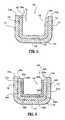
- Deflection control system 240is a dual layered substantially U-shaped channel section 242 configured and dimensioned to be disposed in and between side walls 114 of channel member 112.
- Channel section 242includes an outer channel section 242a and an inner channel section 242b.
- Outer channel section 242ais defined by a pair of parallel spaced apart juxtaposed side walls 244a interconnected by a base wall 246a.
- side walls 244a of channel section 242apreferably have a height which is less than a height of side walls 114 of channel member 112 thus defining a first reveal 250a.
- Inner channel section 242bis defined by a pair of parallel spaced apart juxtaposed side walls 244b interconnected by a base wall 246b.
- side walls 244b of channel section 242bpreferably have a height which is less than a height of side walls 244a of channel section 242a thus defining a second reveal 250b.
- inner channel section 242bis pinned by a cam member (not shown) near intersecting point 112c, secured to outer channel section 242a at a region proximal of intermediate point 112c and is secured at a region near the distal tip (see FIG. 4 ,).
- Inner channel section 242bis likewise preferably secured to outer channel section 242a via pinning or in any manner as described above with regard to channel section 142 of FIGS. 3-5 .
- deflection control system 240When tissue having a relatively smaller thickness is clamped between distal ends 104a, 102a of anvil half-section 104 and cartridge receiving half-section 102 deflection control system 240 functions basically the same manner as deflection control system 140. When tissue having a relatively larger thickness is clamped between distal ends 104a, 102a of anvil half-section 104 and cartridge receiving half-section 102, channel section 242 of deflection control system 240 causes distal end 104a of anvil half-section 104 to undergo a three-stage deflection.
- the deflection forceacts solely on edge surfaces 114a of side walls 114 of channel member 112 resulting in distal end 104a of anvil half-section 104 undergoing an initial rate of deflection in direction "Y" until height "X" of reveal 250a, between side walls 244a of outer channel section 242a and side walls 114 of channel member 112 is reduced to zero (i.e., the height of side walls 244a of outer channel section 242a are even with the height of side walls 114 of channel member 112).
- edge surfaces 114a and 245a of respective side walls 114 and 244aare each in contact with the underside of tissue contacting surfaces 118 of anvil plate 108 thereby making distal end 104a of anvil half-section 104 stiffer and/or more rigid thus reducing its tendency to deflect.
- each edge surface 114a, 245a of side walls 114 and 244a, respectively,is in contact with the underside of tissue contacting surfaces 118 of anvil plate 108 and distal end 104a of anvil half-section 104 undergoes a second stage of deflection. Since the deflecting force must now act on side walls 114 and 244a, distal end 104a of anvil half-section 104 is effectively reinforced and stiffened from this time forward.
- channel section 242 of deflection control system 240causes distal end 104a of anvil half-section 104 to undergo a second degree of deflection which is less than the initial degree of deflection at a second rate of deflection which is less than the initial rate of deflection.
- distal end 104a of anvil half-section 104 and outer channel section 242adeflect, in direction "Y", until reveal 250b between side walls 244b of inner channel section 242b and side walls 244a of outer channel section 242a is reduced to zero.
- edge surfaces 114a, 245a and 245b of respective side walls 114, 244a and 244bare in contact with the underside of tissue contacting surfaces 118 of anvil plate 108 thereby making distal end 104a of anvil half-section 104 still more stiffer and/or still more rigid thus further reducing the tendency of distal end 104a of anvil half-section 104 to deflect.
- each edge surface 114a, 245a and 245b of side walls 114, 244a and 244b, respectively,is in contact with the underside of tissue contacting surfaces 118 of anvil plate 108 and distal end 104a of anvil half-section 104 undergoes a third stage of deflection. Since the deflecting force must now act on side walls 114, 244a and 244b, distal end 104a of anvil half-section 104 is effectively further reinforced and stiffened from this time forward.
- Channel sections 242a and 242bare each preferably made from a rigid material, such as for example, steel. While steel is preferred, it is contemplated that each of channel section 242a and 242b can each be fabricated from other materials, such as, for example, titanium, polycarbonate, fiber glass, resins and the like or any combination thereof.
- Side walls 244a of outer channel section 242a and side walls 244b of inner channel section 242beach preferably have a uniform height along their respective lengths. However, it is contemplated that side walls 244a of outer channel section 242a and side walls 244b of inner channel section 242b can have varying heights along their lengths. Preferably, side walls 244a of outer channel section 242a and side walls 244b of inner channel section 242b each have a uniform thickness, however, it is envisioned that they can have varying thicknesses along their lengths. The height and thickness of each side wall 244a of outer channel section 242a and of each side wall 244b of inner channel section 242b is specifically selected depending on the degree of stiffness desired and on which regions of anvil half-section 104 are desired to be stiffened.
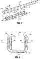
- Deflection control system 340includes a pair of parallel spaced apart juxtaposed reinforcing plates and/or ribs 344, each one to be secured to a respective side wall 114 of channel member 112.
- Each reinforcing rib 344is preferably secured to a respective side wall 114 of channel member 112 at a region proximal of intermediate point 112c (See FIG. 4 ).
- each reinforcing rib 344is secured to its respective side wall 114 by being welded or pinned at a location proximal of intermediate point 112c.
- Other methods of securing reinforcing ribs 344 to side walls 114are contemplated, such as, for example, gluing, adhering, peening and the like.
- Each reinforcing rib 344is preferably made from stainless steel and has a uniform height and thickness. In particular, reinforcing ribs 344 preferably have a height which is less than a height of side walls 114 of channel member 112 thus defining a reveal 350.
- deflection control system 340When tissue having a relatively smaller thickness is clamped between distal ends 104a, 102a of anvil half-section 104 and cartridge receiving half-section 102, deflection control system 340 functions in the same manner as described above for control system 140. As seen in FIGS. 9 and 10 , when tissue having a relatively larger thickness is clamped between distal ends 104a, 102a of anvil half-section 104 and cartridge receiving half-section 102, reinforcing ribs 344 of deflection control system 340 causes distal end 104a of anvil half-section 104 to undergo a two-stage deflection.
- the deflection forceacts solely on edge surfaces 114a of side walls 114 of channel member 112 resulting in distal end 104a of anvil half-section 104 undergoing an initial rate of deflection in direction "Y" until reveal 350 between reinforcing ribs 344 and side walls 114 of channel member 112 is reduced to zero (i.e., the height or edges of reinforcing ribs 344 are even with the height or edges of side walls 114 of channel section 112).
- tissue gap "G”is urged from its initial tapered configuration to a second configuration which is less tapered (i.e., less angled) than the initial tapered configuration or substantially uniform.
- edge surfaces 114a of side walls 114 and edge surfaces 344a of reinforcing rib 344are in contact with the underside of tissue contacting surfaces 118 of anvil plate 108 thereby making distal end 104a of anvil half-section 104 stiffer and/or more rigid thus reducing the tendency of distal end 104a of anvil half-section 104 to deflect.
- each edge surface 114a, 344a of side walls 114 and of reinforcing rib 344, respectively,are in contact with the underside of tissue contacting surfaces 118 of anvil plate 108 and distal end 104a of anvil half-section 104 undergoes a second stage of deflection.
- deflection control system 340causes distal end 104a of the anvil half-section 104 to undergo a rate of deflection which is less than the initial rate of deflection.
- the height of tissue gap "G"is urged from its second less tapered configuration to a configuration having a substantially uniform dimension (i.e., uniform height) from the distal end to the proximal end.
- Deflection control system 340in effect prevents the distal end of tissue gap "G" from having a reverse tapered configuration (i.e., the distal end having a larger height than the proximal end).
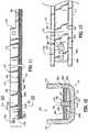
- Deflection control system 460is generally in the form of a leaf-spring and includes a layered reinforcing member 462 (see FIG. 12 ) having a plurality of individual reinforcing plates (e.g., 462a, 462b and 462c) extending longitudinally between side walls 114 of channel member 112 and resting atop base wall 116. While deflection control system 460 is shown as having three reinforcing members, it is envisioned that deflection control system 460 can have any number of reinforcing members, including, and not limited to, one, two, four, etc.
- Deflection control system 460further includes a pin member 468 extending through a series of elongate slots 470 formed in reinforcing member 462.
- a proximal end 464 of reinforcing member 462is fixedly secured to channel member 112, by means of welding, riveting and the like, at a location proximal of intermediate portion 112c while a distal end 466 of reinforcing member 462 is preferably slidably secured to distal end 112a by pin member 468.
- Distal end 466 of reinforcing member 462is preferably pinned at a location proximate to the distal-most edge 112d of channel member 112.
- Pin member 468includes a body portion 472 having a first end 474 fixedly secured to base wall 116 of channel member 112 and a second end 476 extending through reinforcing member 462, and an enlarged head 478 secured to second end 476.
- Head 478is configured and dimensioned to be larger than elongate slots 470 and to rest on the upper-most reinforcing plate.
- Body portion 472 of pin member 468is dimensioned such that head 478 maintains reinforcing plates 462a-462c in sliding contact with one another. While it is preferred that pin member 468 extend through base wall 116 of channel member 112 it is envisioned that pin member 468 can extend through side walls 114 of channel member 112 at a location to engage reinforcing member 462.
- Reinforcing member 462includes a first reinforcing plate 462a having a first elongate slot 470a formed therein and extending in a longitudinal direction, wherein first elongate slot 470a has a first length.
- Reinforcing member 462further includes a second reinforcing plate 462b having a second elongate slot 470b formed therein and extending in a longitudinal direction, wherein second elongate slot 470b has a second length which is greater than the first length of first elongate slot 470a.
- Reinforcing member 462further includes a third reinforcing plate 462c having a third elongate slot 470c formed therein and extending in a longitudinal direction, wherein third elongate slot 470c has a third length which is greater than the second length of second elongate slot 470b.
- reinforcing member 462increases the rigidity of channel member 112 only after channel member 112 has undergone a predetermined amount of deflection in direction "Y", to thereby reduce the rate of deflection of distal end 112a of channel member 112. Accordingly, when tissue having a relatively small thickness is clamped between distal ends 104a, 102a of anvil half-section 104 and cartridge receiving half-section, distal end 104a of anvil half-section 104 will tend to deflect an amount sufficient for tissue gap "G" to have a substantially uniform dimension from the proximal end to the distal end thereof.
- deflection control system 460causes distal end 104a of anvil half-section 104 to undergo a four-stage deflection.
- distal end 112a of channel member 112undergoes an initial rate of deflection, in direction "Y", until the distal surface of first slot 470a of first reinforcement plate 462a contacts pin member 468 thus beginning a second stage of deflection.
- distal end 112a of channel member 112 and first reinforcement plate 462aundergo a second rate of deflection, in direction "Y", until the distal surface of second slot 470b of second reinforcement plate 462b contacts pin member 468, thus beginning a third stage of deflection. Since the deflection force is now acting on distal end 112a of channel member 112 of anvil half-section 104 and on first reinforcement plate 462a, the second rate of deflection is less than the first rate of deflection.
- distal end 112a of channel member 112 and both first and second reinforcement plates 462a and 462bundergo a third rate of deflection, in direction "Y", until the distal surface of third slot 470c of third reinforcement plate 462c contacts pin member 468, thus beginning a fourth stage of deflection. Since the deflection force is now acting on distal end 112a of channel member 112 and both first and second reinforcement plates 462a and 462b, the third rate of deflection is less than the second rate of deflection.
- distal end 112a of channel member 112 and each of first, second and third reinforcement plates 462a-462cundergo a fourth rate of deflection, in direction "Y". Since the deflection force is now acting on distal end 112a of channel member 112 and on each of first, second and third reinforcement plates 462a-462c, the fourth rate of deflection is less than the third rate of deflection.
- distal end 112a of channel member 112is further stiffened by the interaction of deflection control system 460 with distal end 112a of channel member 112.
- Deflection control system 460will permit distal end 112a to deflect an initial amount, in direction "Y", in a manner similar to if deflection control system 460 was not provided.
- deflection control system 460is engaged and distal end 112a of channel member 112 is stiffened.
- deflection control system 460can provide distal end 112a of channel member 112 with multiple stages of incremental stiffening, however, it is within the scope of the present disclosure that deflection control system 460 provides distal end 112a of channel member 112 with a single stage of stiffening.
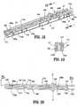
- Deflection control system 560is generally in the form of a leaf-spring and includes a layered reinforcing member 562 having a plurality of individual reinforcing plates (e.g., 562a, 562b and 562c) extending longitudinally between side walls 114 of channel member 112 and resting atop base wall 116.
- Deflection control system 560further includes a pair of juxtaposed shoulders 580 preferably integrally formed with and extending transversely from an inner surface of side walls 114 of channel member 112. While a pair of integral shoulders 580 are shown, it is contemplated that shoulders 580 can be formed from elements (i.e., bolts, screws, pins, brackets, etc.) extending through side walls 114.
- Each shoulder 580includes a body portion 582 having a height greater than reinforcing member 562 and a head portion 584 configured and dimensioned to overlie reinforcing member 562.
- Body portion 582 of shoulders 580preferably extends into a series of elongate recesses 590 formed along the lateral sides of reinforcing member 562.
- a proximal end of 564 reinforcing member 562is fixedly secured to channel member 112, by means of welding, riveting and the like, at a location proximal of intermediate portion 112c while a distal end of reinforcing member 562 is preferably slidably coupled to distal end 112a via shoulders 580.
- Reinforcing member 562includes a first reinforcing plate 562a having a first pair of elongate recesses 590a formed along each lateral side thereof and extending in a longitudinal direction, wherein the first pair of elongate recesses 590a has a first length.
- Reinforcing member 562further includes a second reinforcing plate 562b having a second pair of elongate recesses 590b formed in each lateral side thereof and extending in a longitudinal direction, wherein the second pair of elongate recesses 590b has a second length which is greater than the first length of first pair of elongate recesses 590a.
- Reinforcing member 562further includes a third reinforcing plate 562c having a third pair of elongate recesses 590c formed in each lateral side thereof and extending in a longitudinal direction, wherein the third pair of elongate recesses 590c has a third length which is greater than the second length of the second pair of elongate recesses 590b.
- reinforcing member 562functions in the same manner as reinforcing member 562.
- reinforcing member 562increases the rigidity of channel member 112 only after channel member 112 has undergone a predetermined amount of deflection in direction "Y".
- deflection control system 560causes distal end 104a of anvil half-section 104 to undergo a four-stage deflection.
- distal end 112a of channel member 112undergoes an initial rate of deflection, in direction "Y", until the distal surfaces of the first pair of recesses 590a of first reinforcement plate 562a contacts shoulders 580 thus beginning a second stage of deflection.
- distal end 112a of channel member 112 and first reinforcement plate 562aundergo a second rate of deflection, in direction "Y", until the distal surfaces of the second pair of recesses 590b of second reinforcement plate 562b contacts shoulders 580, thus beginning a third stage of deflection. Since the deflection force is now acting on distal end 112a of channel member 112 of anvil half-section 104 and on first reinforcement plate 562a, the second rate of deflection is less than the first rate of deflection.
- distal end 112a of channel member 112 and both first and second reinforcement plates 562a and 562bundergo a third rate of deflection, in direction "Y", until the distal surfaces of the third pair of recesses 590c of third reinforcement plate 562c contacts shoulders 580, thus beginning a fourth stage of deflection. Since the deflection force is now acting on distal end 112a of channel member 112 and both first and second reinforcement plates 562a and 562b, the third rate of deflection is less than the second rate of deflection.
- distal end 112a of channel member 112 and each of first, second and third reinforcement plates 562a-562cundergo a fourth rate of deflection, in direction "Y". Since the deflection force is now acting on distal end 112a of channel member 112 and on each of first, second and third reinforcement plates 562a-562c, the fourth rate of deflection is less than third rate of deflection.
- distal end 112a of channel member 112is further stiffened by the interaction of deflection control system 560 with distal end 112a of channel member 112.
- deflection control system 560can provide distal end 112a of channel member 112 with multiple stages of stiffening, however, it is within the scope of the present disclosure that deflection control system 560 provides distal end 112a of channel member 112 with a single stage of stiffening.
- reinforcing plates 462a-462c and reinforcing plates 562a-562ccan each have a different thickness from a distal end to a proximal end thereof.
- the degree of stiffening created by each reinforcing plate 462a-462cwill be different.
- a relatively thicker reinforcing platewill result in a greater degree of stiffening while a relatively thinner reinforcing plate will result in a lesser degree of stiffening.
- reinforcing plate 462ais shown as the thickest (i.e., providing the greatest degree of stiffening) and reinforcing plate 462c is shown as the thinnest (i.e., providing the least degree of stiffening), it is contemplated that the position of reinforcing plates 462a and 462c can be reversed. It is further contemplated that any combination of thicknesses and relative position of reinforcing plates 462a-462c can be provided to achieve a desired degree and rate of stiffening of distal end 112a of channel member 112.
- Reinforcing plates 462a-462care preferably each fabricated from stainless steel, however, it is contemplated that reinforcing plates can be fabricated from any material capable of increasing the rigidity of distal end 112a of channel member 112, such as, for example, titanium, polycarbonate, fiberglass, resins and the like or any combination thereof.
- the deflection systemhas a low profile or that the deflection system is situated to the lateral sides of channel member 112. In this manner, deflection systems will not result in the alteration of the depth of knife track 122 and/or the operation of the knife blade (not shown) reciprocatingly disposed within knife track 122.
- FIG. 17is a graph illustrating the effects of use of any of the deflection control systems disclosed herein. As seen in FIG. 17 , for deflection control systems having a reveal of about 0.004 to about 0.006 inches (0.1016 to about 0.1524 mm) a change in the rate of deflection, as evidenced by a change in the slope of the corresponding plot, is experienced at approximately 15 lbs (67 N). Also as seen in FIG. 17 , for deflection control systems having a reveal of about 0.010 inches (0.25 mm) a change in the rate of deflection, as evidenced by a change in the slope of the corresponding plot, is experienced at approximately 34 lbs (151 N).
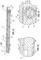
- Deflection control system 640includes a pair of parallel spaced apart juxtaposed reinforcing plates and/or ribs 344, each one secured to a respective side wall 114 of channel member 112.
- each reinforcing rib 344is secured to side walls 114 of channel member 112 by welds 346.
- At least one weld 346preferably a pair of welds 346a, 346b can be used to secure each reinforcing rib 344 to side wall 114.
- welds 346aare provided near distal tip 112d of channel member 112 and welds 346b are provided near intermediate point 112c of channel member 112.
- welds 346bare provided proximal of intermediate point 112c of channel member 112 and of cam member 400 of anvil half-section 104. (see FIGS. 2 , 18 and 20 )
- each reinforcing rib 344is welded to a respective side wall 114 such that an upper surface 344d of reinforcing rib 344 contacts or substantially contacts an inner surface 116a of base wall 116.
- a distal end 344b of reinforcing rib 344is welded to side wall 114 such that upper surface 344d of reinforcing rib 344 is in contact with inner surface 116a of base wall 116.
- a proximal end 344c of reinforcing rib 344is welded to side wall 114 such that upper surface 344d of reinforcing rib 344 is spaced a distance from inner surface 116a of base wall 116.
- each reinforcing rib 344includes a through hole H" at or near proximal end 344c thereof which aligns with and/or is in registration with a slot or hole H' formed in each side wall 114 of channel member 112 at or adjacent intermediate point 112c of channel member 112.
- a pin or cam member 400extends through aligned holes H' of channel member 112 and through holes H" of each reinforcing rib 344, and in turn extend transversely through side walls 114 of channel member 112 of anvil half-section 104.
- Such a cam member 400 and the manner in which it operatesis disclosed in International Appl. Ser. No. PCT/US03/08342 filed on March 13, 2003 .
- through-hole H" of each reinforcing rib 344has a diameter "D1” and the portion of cam 400 extending through through-hole H" of each reinforcing rib 344 has a diameter "D2" which is less than diameter "D1" of through-hole H".
- diameter "D1" of through-hole H"is about 0.203 inches (0.51 cm) and diameter "D2" of the portion of cam 400 extending through-hole H” is about 0.200 inches (0.5 cm) thereby defining a reveal of about 0.003 inches (0.07 mm).
- distal end 104a of anvil half-section 104will tend to deflect an amount sufficient for tissue gap "G" to have a substantially uniform dimension from the proximal end to the distal end thereof.
- deflection control system 640causes distal end 104a of anvil half-section 104 to undergo a two-stage deflection.
- the rate of deflectionis established when distal end 112a of channel member 112 and distal end 344b of reinforcing ribs 344 are loaded with a force.
- the rate of deflectionwill be at a maximum to allow the tissue gap "G" to be set relatively quickly.
- This maximum rate of deflectionis attained from the existent of the reveal between through-hole H" of each reinforcing rib 344 and the portion of cam 400 extending through through-hole H" of each reinforcing rib 344.
- the rate of deflectionneeds to be reduced and/or at a minimum in order to maintain the proper tissue gap "G" for staple formation.
- This reduced rate of deflectionis attained as a result of the size of the reveal between through-hole H" of each reinforcing rib 344 and the portion of cam 400 extending through through-hole H" of each reinforcing rib 344 being reduced to zero.
- the rate of deflectionis decreased to a desired and/or optimum rate.
- each reinforcing rib 344is welded to side walls 114, each reinforcing rib 344 travels with channel member 112.
- deflection control system 640causes distal end 104a of anvil half-section 104 to undergo a rate of deflection which is less than the initial rate of deflection.
- proximal end 344cis prevented from moving further in the direction opposite to arrow "Y".
- Deflection control system 640in effect prevents the distal end of tissue gap "G" from having a reverse tapered configuration (i.e., the distal end having a larger height than the proximal end).
- surgical stapling apparatus 100can be provided with directionally biased formable staples and/or be provided with anvil pockets for forming the staples in a predetermined manner.
- Such a surgical stapling apparatusis disclosed in U.S. Appl. Ser. No. 09/693,379 filed on October 20, 2000 , entitled "Directionally Biased Staples and Cartridge Having Directionally Biased Staples'.
- the deflection control systemsreduce the degree and/or amount of deflection of distal end 112a of channel member 112, and in turn the degree and/or amount of deflection of distal end 104a of anvil half-section 104, of surgical fastener applying apparatus 100, as compared to a surgical fastener applying apparatus not including a deflection control system according to any of the embodiments disclosed herein.
Landscapes
- Health & Medical Sciences (AREA)
- Life Sciences & Earth Sciences (AREA)
- Surgery (AREA)
- Heart & Thoracic Surgery (AREA)
- Engineering & Computer Science (AREA)
- Biomedical Technology (AREA)
- Nuclear Medicine, Radiotherapy & Molecular Imaging (AREA)
- Medical Informatics (AREA)
- Molecular Biology (AREA)
- Animal Behavior & Ethology (AREA)
- General Health & Medical Sciences (AREA)
- Public Health (AREA)
- Veterinary Medicine (AREA)
- Surgical Instruments (AREA)
Description
- The present disclosure relates to surgical fastener applying apparatus and, more particularly, to surgical fastener applying apparatus that include a deflection control system for controlling and/or reducing the rate of deflection of an anvil beam.
- Surgical fastener applying apparatus, for example, surgical stapling apparatus, have been developed in which a staple cartridge receiving half-section including a staple cartridge assembly provided at a distal end thereof, is operatively connected (e.g., pivotably connected) to an anvil half-section including an anvil provided at a distal end thereof. The staple cartridge assembly preferably includes a plurality of surgical staples which are ejectable therefrom. The staple cartridge assembly may be manufactured as an integral part of the staple cartridge receiving half-section, or the staple cartridge assembly may be designed and manufactured as a disposable loading unit for use in a reusable surgical stapling apparatus.
- Typically, when the distal end of the staple cartridge receiving half-section is approximated toward the distal end of the anvil half-section, to clamp tissue inserted therebetween in preparation for stapling, the opposing surfaces of the distal end of the staple cartridge assembly and the distal end of the anvil assembly are spaced apart by a predetermined distance which is pre-established and fixed for each surgical stapling apparatus. This spacing is sometimes referred to as the "tissue gap" of the surgical stapling apparatus.
- Since it is desirable that the "tissue gap" be substantially uniform and/or "fixed" (i.e., having the same dimension throughout the stapling operation), in order to form lines of uniform staples along the cartridge, the operator of the surgical stapling apparatus needs to ascertain whether the "tissue gap" is loaded with more or thicker tissue than recommended (i.e., overloaded) which may result in undesired or increased deflection of the distal end of the anvil half-section and/or the staple cartridge receiving half-section. As used herein, the term "deflection" is understood to include flexing, bending, deforming, biasing, skewing and the like.
- It is desirable that tissue having a thickness larger, preferably slightly larger, than the height of the "tissue gap" be clamped between the tissue contacting surface of the staple cartridge assembly and the anvil so that when the surgical stapling apparatus is clamped onto the tissue, the tissue substantially fills the entire height of the "tissue gap". However, it has been noticed that clamping of such tissue between the tissue contacting surfaces of the distal ends of the anvil and staple cartridge receiving half-sections tends to cause the distal ends of the anvil and/or staple cartridge receiving half-sections to deflect. The greater the initial and/or resultant thickness of tissue clamped between the distal ends of the staple cartridge receiving and anvil half-section, especially adjacent and at their distal tips, the greater the degree of deflection of the distal end of the anvil half-section and/or the staple cartridge receiving half-section.
- In the past, the deflection at the distal end of the anvil half-section was reduced and/or eliminated by using a relatively heavier construction (i.e., thicker structural elements), a relatively larger construction or relatively stronger materials. These approaches increase the size and/or cost of the surgical stapling apparatus.
WO03079909 - It would be desirable to provide a surgical stapling apparatus that includes a deflection control system for controlling and/or reducing the rate and/or degree of deflection of the distal end of the anvil half-section when tissue is clamped between the distal ends of the anvil and staple cartridge receiving half-sections.
- It would also be desirable to provide a surgical stapling apparatus that has a deflection control system which allows rapid initial deflection of the distal end of the anvil half-section to a specific value and which thereafter causes a decrease or reduction in the rate and/or degree of deflection in a predetermined manner.
- It would also be desirable to provide a surgical stapling apparatus that includes a deflection control system which allows rapid initial deflection of the distal end of the anvil half-section to efficaciously achieve the optimal tissue gap when clamping relatively thin tissue and which thereafter reduces the rate of deflection in relatively thicker tissue to maintain the tissue gap as close as possible to the optimal tissue gap.
- Surgical stapling apparatus constructed in this manner would allow for rapid deflection of the distal end of the anvil half-section to a specific value followed by a decrease in the rate of deflection of the same. Accordingly, the distal end of the anvil half-section is able to deflect quickly to the optimal tissue gap in relatively thin tissue and deflect slowly in relatively thicker tissue to remain as close as possible to the optimal tissue gap.
- The invention is defined in the appended claims.
- According to an aspect of the present disclosure, a surgical fastener applying apparatus is provided including an anvil half-section including a distal end and a proximal end defining a longitudinal axis, a cartridge receiving half-section including a distal end, and a deflection control system operatively associated with the anvil half-section. The cartridge receiving half-section is desirably operatively couplable with the anvil half-section such that the distal end of the anvil half-section is movable into juxtaposed relation to the distal end of the cartridge receiving half-section. A tissue gap is defined between the distal end of the anvil half-section and the distal end of the cartridge receiving half-section when the anvil and cartridge half-sections are coupled together.
- The deflection control system is configured and adapted to reinforce the distal end of the anvil half-section when a force is applied there in a direction transverse to the longitudinal axis.
- In addition, the anvil half-section defines a tissue contacting surface. Accordingly, the deflection control system reinforces the distal end of the anvil half-section when a force is applied to the distal end of the anvil half-section in a direction transverse to the longitudinal axis and normal to a plane defined by the tissue contacting surface of the anvil half-section.
- In one embodiment, the anvil half-section includes a U-shaped channel member having a pair of side walls interconnected by a base wall. In this embodiment, the deflection control system is operatively associated with the channel member. The deflection control system is desirably operatively disposed within the channel member.
- According to one embodiment, the deflection control system can include a U-shaped channel section having a pair of side walls interconnected by a base wall. Preferably, the base wall of the channel section of the deflection control system is adjacent, more preferably in contact with the base wall of the channel member of the anvil half-section, and the side walls of the channel section are disposed interior of and adjacent the side walls of the channel member. It is envisioned that each side wall of the pair of side walls of the channel section has a height which is less than a height of a respective one of the pair of side walls of the channel member thereby defining a reveal along each side wall of the pair of side walls of the channel member. Preferably, the relative height of each side wall of the pair of side walls of the channel section is uniform along a length thereof, and each side wall of the pair of side walls of the channel section preferably has a uniform thickness along a length thereof.
- Desirably, at least a proximal end of the channel section is fixedly secured to a proximal end of the channel member.
- It is envisioned that the deflection control system can be a multi-stage system, e.g., a two-stage system, a three-stage system, a four-stage system, etc. In a two-stage system, the deflection control system begins reducing the rate of deflection of the distal end of the channel member in a second stage of deflection. The second stage of deflection desirably takes effect when the reveal between the side walls of the channel member and the side walls of the channel section is about zero. Accordingly, the distal end of the channel member and the distal end of the channel section deflect concomitantly.
- The deflection control system functions such that the greater the rate of deflection of the distal end of the channel member, the greater the reduction in the rate at which the distal end of the channel section deflects. It is contemplated that the reveal between the distal end of the channel member and the distal end of the channel section can be zero.
- According to another embodiment of the present disclosure, the deflection control system can include a first U-shaped channel section having a pair of side walls interconnected by a base wall, wherein the base wall of the first channel section of the deflection control system is adjacent to or, more preferably in contact with the base wall of the channel member of the anvil half-section, and a second U-shaped channel section having a pair of side walls interconnected by a base wall, wherein the base wall of the second channel section of the deflection control system is adjacent to or, more preferably in contact with the base wall of the first channel section of the deflection control system.
- A distal end of each side wall of the pair of side walls of the first channel section can have a height which is less than a height of a respective side wall of the pair of side walls of the channel member thereby defining a first reveal along each of the pair of side walls of the channel member. In addition, each side wall of the pair of side walls of the second channel section can have a height which is less than a height of the respective side walls of the pair of side walls of the first channel section thereby defining a second reveal along a distal end of each side wall of the pair of side walls of the second channel section.
- A proximal end of each of the first and second channel sections can be operatively fixedly secured to a proximal end the channel member. It is contemplated that the height of the distal end of each side wall of the pair of side walls of the first channel section and the height of a corresponding distal end of each side wall of the pair of side walls of the second channel section are uniform along each of the lengths thereof.
- In this embodiment the deflection control system is a three-stage system. In a three-stage system the deflection control system begins reducing the rate of deflection of the distal end of the channel section in a second stage of deflection, and in a third stage of deflection the deflection control system reduces the rate of deflection of the distal end of the channel member by an additional amount. In operation, the second stage of deflection engages when the first reveal between the side walls of the channel member and the side walls of the first channel section is about zero, whereby the distal end of the channel member and the distal end of the first channel section deflect concomitantly. The third stage of deflection engages when the second reveal between the side walls of the first channel section and the side walls of the second channel section is about zero, whereby the distal end of the channel member, the distal end of the first channel section and the distal end of the second channel section deflect concomitantly.
- According to another embodiment the deflection control system includes a pair of reinforcing ribs each disposed along an inner surface of a respective side wall of the pair of side walls of the channel member. Each rib of the pair of reinforcing ribs of the deflection control system has a height which is less than the height of the respective side walls of the channel member thereby defining a reveal along each of the pair of side walls of the channel member. It is envisioned that a proximal end of each of the pair of reinforcing ribs is pinned to a portion of the proximal end of the channel member.
- In another embodiment, a proximal end of the deflection control system is fixedly secured to a portion of the proximal end of the channel member and a portion of the distal end of the deflection control system is longitudinally slidingly coupled to the channel member. The deflection control system can include at least one, preferably a plurality of, reinforcing plate(s) adjacent, preferably in contact with the base wall of the channel member.
- In this embodiment, the surgical fastener applying apparatus can further include a pin member fixedly secured to the base wall of the channel member. The distal end of each of the plurality of reinforcing plates is slidingly coupled to the channel member by the pin member extending through a plurality of elongate longitudinally oriented slots formed, one each, in the plurality of respective reinforcing plates. The elongate slots preferably increase in length from the reinforcing plate which is closest to the base wall of the channel member to the reinforcing plate which is furthest from the base wall of the channel member. The slots of the plates each have a proximal edge, and desirably the proximal edges are in registration with one another. The pin member desirably includes a head secured to an end thereof that is opposite to the base wall. The head engages the reinforcement plates and forces the distal end of each of the reinforcing plates to deflect concomitantly with the distal end of channel member.
- In operation, as the distal end of the channel member and the deflection control system deflect in a direction transverse to the longitudinal axis, the distal end of at least one of the plurality of reinforcing plates translates in a longitudinal direction. The deflection control system is a multi-stage system which begins to incrementally reduce the rate of deflection of the distal end of the channel member as a distal end of each elongate slot of each respective reinforcing plate engages the pin member. The deflection control system incrementally reduces the rate at which the distal end of the channel member deflects.
- In another embodiment, surgical fastener applying apparatus can be provided with a pair of juxtaposed shoulders each extending from an inner surface of the side walls of the channel member in a distal end thereof. Each reinforcing plate can include an elongate recesses formed along each lateral side thereof and in operative engagement with a respective one of the pair of shoulders. The elongate recesses preferably increase in length from the reinforcing plate which is closest to the base wall of the channel member to the reinforcing plate which is furthest from the base wall of the channel member. Each of the elongate recesses has a proximal edge and wherein the proximal edges are in registration with one another. Each shoulder preferably includes a head portion secured to an end thereof, the head portion being configured and dimensioned to force the distal end of each of the reinforcing plates to deflect concomitantly with the distal end of channel member.
- In operation, as the distal end of the channel member and the deflection system deflect in a direction transverse to the longitudinal axis the distal end of each of the plurality of reinforcing plates translates in a longitudinal direction. The deflection control system is a multi-stage system, wherein the deflection control system begins to incrementally reduce the rate of deflection of the distal end of the channel member as a distal end of each elongate recess of each respective reinforcing plate engages a respective shoulder, the deflection control system incrementally reduces the rate at which the distal end of the channel member deflects.
- According to another aspect of the present disclosure, a deflection control system is provided for a surgical fastener applying apparatus that includes an anvil half-section having a channel member and a cartridge receiving half-section operatively couplable to the anvil half-section. The deflection control system includes an elongate reinforcing assembly having a proximal end operatively engaged with a proximal end of the channel member and a distal end operatively associated with a distal end of the channel member, wherein the reinforcing assembly incrementally reduces deflection of the distal end of the channel member when forces are applied to the distal end of the channel member in a direction transverse to a longitudinal axis of the channel member and normal to a tissue contacting surface of the anvil half-section.
- According to another aspect of the present disclosure, a surgical fastener applying apparatus is provided. It includes an anvil half-section including a distal end and a proximal end defining a longitudinal axis, the anvil half-section including a channel member having pair of juxtaposed side walls interconnected by a base wall, each side wall defining a through hole having a diameter. The apparatus further includes a cartridge receiving half-section including a distal end, wherein the cartridge receiving half-section is couplable with the anvil half-section such that the distal end of the anvil half-section is movable into juxtaposed relation to the distal end of the cartridge receiving half-section. The distal ends of the anvil and cartridge half-sections can be pivotable about a pivot axis transverse to the longitudinal axis.
- The surgical fastener applying apparatus further includes a deflection control system operatively associated with the anvil half-section for reinforcing the distal end of the anvil half-section when a force is applied to the distal end of the anvil half-section in a direction transverse to the longitudinal axis. The deflection control system most preferably includes a pair of reinforcing ribs having a distal end and a proximal end. The distal end of each reinforcing rib is fixedly secured to an inner surface of a respective side wall of the pair of side walls of the channel member and the proximal end of each reinforcing rib extends beyond the pivot axis. The proximal end of each reinforcing rib defines a hole in registration with the through hole defined in the side walls of the channel member. The holes are desirably positioned proximal of the pivot axis. The deflection control system further includes a cam member extending through the holes formed in each side wall of the channel member and each reinforcing rib, the cam having a diameter smaller than the diameter of the through hole formed in each reinforcing rib to thereby define a reveal between each reinforcing rib and the cam member.
- This deflection control system is a two-stage system. Accordingly, in operation, the deflection control system begins reducing the degree and the rate of deflection of the distal end of the channel member in a second stage of deflection. The second stage of deflection takes effect when the reveal between an upper portion of the hole formed in each reinforcing rib and an upper portion of the cam is zero.
- Further features of the disclosure, its nature and various advantages will be more apparent from the accompanying drawings and the following detailed description.
- By way of example only, preferred embodiments of the present disclosure will be described herein with reference to the accompanying drawings, in which:
FIG. 1 is a perspective view of a surgical fastener applying apparatus in accordance with the present disclosure;FIG. 2 is a side elevational view showing the distal end of the surgical fastener applying apparatus ofFIG. 1 ;FIG. 3 is a top perspective view, with parts separated, of an anvil half-section of the surgical fastener applying apparatus ofFIG. 1 ;FIG 4 is a bottom perspective view of an anvil half-section channel member of the anvil half-section ofFIG. 3 ;FIG. 5 is a transverse cross-sectional view of a portion of the distal end of the channel member ofFIG. 4 , as taken along section line 5 - 5 ofFIG. 4 ;FIG. 6 is a transverse cross-sectional view of a portion of the distal end of a channel member, in accordance with an alternative embodiment of the present disclosure, as would be seen along section line 5 - 5 ofFIG. 4 ;FIG. 7 is a bottom perspective view, with parts separated, of the distal end of an anvil half-section, in accordance with another embodiment of the present disclosure;FIG. 8 is a transverse cross-sectional view of a portion of the distal end of a channel member of the assembled parts of the anvil half section ofFIG. 8 , as would be seen along section line 8 - 8 ofFIG. 7 ;FIG. 9 is a longitudinal cross-sectional view of a portion of the distal end of the channel member ofFIGS. 7 and 8 when no load is applied to a distal end thereof;FIG. 10 is a longitudinal cross-sectional view of a portion of the distal end of the channel member ofFIG. 9 having a load applied to a distal end thereof;FIG. 11 is a longitudinal cross-sectional view of the distal end of an anvil half-section of a channel member in accordance with yet another alternative embodiment of the present disclosure;FIG. 12 is a transverse cross-sectional view of a portion of the distal end of the channel member ofFIG. 11 , as would be seen along line 12 - 12 ofFIG. 11 ;FIG. 13 is a bottom plan view of a portion of the distal end of the channel member ofFIGS. 11 and 12 ;FIG. 14 is a longitudinal cross-sectional view of a portion of the distal end of a channel member of an anvil half-section in accordance with yet another alternative embodiment of the present disclosure;FIG. 15 is a transverse cross-sectional view of a distal end portion of the channel member ofFIG. 14 , as would be seen along line 15 - 15 ofFIG. 14 ;FIG. 16 is a top plan view of a portion of the distal end of the channel member ofFIGS. 14 and 15 ;FIG. 17 is a graph illustrating the effects of the use of a deflection control system, in accordance with the present disclosure, in an anvil half-section;FIG. 18 is a bottom perspective view of a portion of the distal end of a channel member of an anvil half-section, in accordance with another embodiment of the present disclosure;FIG. 19 is a transverse cross-sectional view of the channel member ofFIG. 18 , as would be seen along line 19 - 19 ofFIG. 18 ;FIG. 20 is a bottom plan view of the distal end of the channel member ofFIG. 18 ;FIG. 21 is a longitudinal cross-sectional view of a portion of the distal end of the channel member ofFIGS. 18 and 19 , as would be seen along section line 21 - 21 ofFIG. 20 ;FIG. 22 is an enlarged view of the area indicated 22 ofFIG. 21 ; andFIG. 23 is an enlarged view of the area indicated 23 ofFIG. 21 .- Preferred embodiments of the presently disclosed surgical fastener applying apparatus will now be described in detail with reference to the drawing figures wherein like reference numerals identify similar or identical elements. In the drawings and in the description which follows, the term "proximal" will refer to the end of the surgical fastener applying apparatus which is closest to the operator, while the term "distal" will refer to the end of the surgical fastener applying apparatus which is furthest from the operator.
- Referring to
FIGS. 1-5 , a surgical fastener applying apparatus, in accordance with the present disclosure, is shown generally as 100.Apparatus 100 is particularly adapted to apply surgical staples and includes a cartridge receiving half-section 102, an anvil half-section 104 operatively coupled to cartridge receiving half-section 102, astaple cartridge assembly 106 fixedly or removably supported in adistal end 102a of cartridge receiving half-section 102 and ananvil plate 108 fixedly or removably supported on adistal end 104a of anvil half-section 104. - For purposes of illustration, the present disclosure describes beam deflection control systems with specific reference to a surgical fastener applying apparatus, preferably a surgical stapler. It is envisioned, however, that the beam deflection control system and illustrative embodiments herein may be incorporated in any surgical fastener applying apparatus having at least one cantilevered beam member which may be subject to deflection under an applied load which has a force component transverse to the longitudinal axis of the beam. It is further envisioned that the beam deflection control system and illustrative embodiments disclosed herein may be incorporated into and/or equally applied to endoscopic, laparoscopic as well as open type surgical instruments. The "beam" referred to in "beam deflection control system" can be
distal end 102a of cartridge half-section 102, and/ordistal end 104a of anvil half-section 104, although most of the discussion herein will refer to the distal end of the anvil half-section because, of the two, typically it is the member which deflects the most. - As seen in
FIG. 2 , when anvil half-section 104 is operatively coupled to cartridge receiving half-section 102, a tissue gap "G" exists betweendistal end 104a of anvil half-section 104 anddistal end 102a of cartridge receiving half-section 102. Tissue gap "G" is typically set to a predetermined dimension during the manufacture ofsurgical stapling apparatus 100 to allow for desired staple formation. Preferably, tissue gap "G" is tapered, i.e., narrower adjacent a distal end ofapparatus 100 than at a location proximal of the distal end ofapparatus 100. As described above with regard to previous surgical fastener applying apparatus, when distal ends 104a of anvil half-section 104 anddistal end 102a of cartridge receiving half-section 102 are clamped onto tissue, a deflection force is exerted thereon, in the directions indicated by arrows "Y" (i.e., in directions transverse to the longitudinal axis of the surgical fastener applying apparatus), tending to causedistal end 104a of anvil half-section 104 and/ordistal end 102a of cartridge receiving half-section 102 to deflect, e.g., in the direction of arrows "Y". As is known in the art, the degree of deflection ofdistal ends section 104 and cartridge receiving half-section 102 tend to increase at locations or in portions increasingly closer to the distal tips thereof. As is also known in the art, the thicker the tissue to be clamped the greater the deflection force exerted. Also, tissue thickness can vary, e.g., increase, during approximation and stapling. This can be due, e.g., to tissue fluid flow typically toward the distal tip of the apparatus during approximation ofdistal ends sections - Thus, the greater the degree of deflection in the direction of arrows "Y", the greater the likelihood that the dimension of the distal end of tissue gap "G" may vary from its predetermined setting. As a result, it may occur that staples (not shown) fired from
staple cartridge assembly 106 may form non-uniformly along the length ofanvil plate 108. In the region where the dimension of tissue gap "G" remains or is close to the predetermined setting, i.e., nearintermediate point 112c (FIG. 3 ) the legs of the staples will form as intended. However, it may occur that if excessively thick over-indicated tissue is inadvertently fastened, the dimension of tissue gap "G" may increase beyond its predetermined setting, e.g., near the distal tip ofanvil plate 108, and there is a possibility that in that area the legs of the staples may not form as desired. The purpose of this disclosure is to reduce the possibility of or prevent this from occurring. Elsewise stated, the purpose of this disclosure is to increase the possibility that even if excessively thick over-indicated tissue is encountered, deflection will be minimized or prevented, to enhance the possibility of and provide for acceptable staple formation. - As seen in
FIG. 3 , anvil half-section 104 includes an anvil half-section channel member 112 having adistal end 112a, a proximal end 112b and a transition orintermediate point 112c.Channel member 112 has a substantially U-shaped transverse cross-sectional profile defined by a pair of substantially parallel juxtaposedside walls 114 interconnected by abase wall 116. Anvil plate 108 is preferably configured and dimensioned to fit overside walls 114 ofdistal end 112a ofchannel member 112. As seen inFIG. 3 ,anvil plate 108 includes a pair oftissue contacting surfaces 118 each having a plurality of staple forming pockets 120 (i.e., anvil pockets, anvil depressions, etc.) formed therein. Preferably,anvil plate 108 includes aknife track 122 extending longitudinally between the pair of tissue contacting surfaces 118. Preferably,knife track 122 interconnects and separates the pair oftissue contacting surfaces 118 from one another.Anvil plate 108 further includes a pair of substantially parallel juxtaposedupstanding side walls 124 extending, one each, from a lateral side edge of the pair of anvil surfaces 118.- Anvil half-
section 104 further includes adistal end cap 126 adapted to be snap-fit onto or into the distal tip ofchannel member 112. Preferably,end cap 126 is tapered to facilitate insertion of the distal tip into the target surgical site. Anvil half-section 104 can also include anend cap 128 to be received between a pair of spaced apart juxtaposed flanges 130 (one shown) extending from proximal end 112b ofchannel member 112. - Anvil half-
section 104 can further include acontoured hand grip 132 configured and adapted to be snap-fit over proximal end 112b ofchannel member 112.Hand grip 132 desirably provides an operator ofsurgical stapling apparatus 100 with improved control and an increased degree of manipulation. - As seen in
FIGS. 3-5 , anvil half-section 104 includes a deflection control system, generally designated 140 for reducing the rate of deflection ofdistal end 112a ofchannel member 112 as the force in direction "Y" increases and as the deflection distance ofdistal end 112a ofchannel member 112 increases. In this embodiment,deflection control system 140 includes a substantiallyU-shaped channel section 142 disposed betweenside walls 114 ofchannel member 112. As best seen inFIG. 5 ,channel section 142 is defined by a pair of parallel spaced apart juxtaposedside walls 144 interconnected by abase wall 146. In particular,side walls 144 ofchannel section 142 preferably have a height which is less than a height ofside walls 114 ofchannel member 112 thus defining areveal 150 having a height "X". - Height "X" of
reveal 150 can be uniform or vary along the entire length ofdistal end 112a ofchannel member 112 anddistal end 142a ofchannel section 142. Although, height "X" can taper in either a distal or a proximal direction, preferably it tapers in a distal direction, e.g., from being narrow or zero near the distal tip to a greater height neartransition point 112c. Reveal 150 can have discrete regions or lengths, each of which, has a different height "X". - Preferably, height "X" is from about 0.004 inches (0.1016 mm) to about 0.10 inches (0.25 cm), more preferably from about 0.004 inches (0.1016 mm) to about 0.006 inches (0.1524 mm). As will be described in greater detail below, when height "X" is about 0.004 inches (0.1016 mm) to about 0.006 inches (0.1524 mm),
distal end 104a of anvil half-section 104 becomes stiffer sooner as compared to when height "X" is greater than 0.006 inches (0.1524 mm). Channel section 142 extends fromdistal end 112a ofchannel member 112 to a portion of proximal end 112b.Channel section 142 is fixedly secured tochannel member 112 preferably at least in a region proximal of but adjacentintermediate point 112c to allowchannel section 142 to be free to float withinchannel member 112 in a region distal ofintermediate point 112c (i.e.,distal end 112a).- It is envisioned that
channel section 142 can be secured at such locations tochannel member 112 at suitable specific predetermined locations along the length thereof. In particular,side walls 144 ofchannel section 142 can be secured to correspondingside walls 114 ofchannel member 112, andbase wall 146 ofchannel section 142 can be secured tobase wall 116 ofchannel member 112. Channel section 142 is preferably secured tochannel member 112 by pinning (i.e., by extending a pin throughchannel section 142 and into an adjacent element or structure of apparatus 100), however, it is envisioned thatchannel section 142 can be secured tochannel member 112 via any number of known techniques, such as, for example, welding, soldering, gluing, peening and the like. Most preferably,channel section 142 is, as will be explained, welded tochannel member 112 and acam 400 can extend throughside walls 144 ofchannel section 142 to pinchannel section 142 toside walls 144.Channel section 142 is made from a rigid material which is resistant to bending, such as, for example, steel. While steel is preferred, it is contemplated thatchannel section 142 can be fabricated from other materials, such as, for example, titanium, polycarbonate, fiberglass, resins and the like, or any combination thereof.- It is further contemplated that each
side wall 144 ofchannel section 142 have a preselected thickness. A relatively smaller thickness provides less rigidity while a relatively larger thickness provides increased rigidity. It is still further contemplated that eachside wall 144 can have a uniform or varying thickness along its length. - In operation,
channel section 142 increases the rigidity of channel member 112 (i.e., reduces the rate of deflection) afterchannel member 112 has undergone a predetermined amount of deflection in direction "Y" (e.g., transverse to a longitudinal axis ofapparatus 100 and substantially normal to the plane of the tissue contacting surface of anvil 108) thereby reducing the rate of deflection ofdistal end 112a ofchannel member 112. As will be used herein, the recitation "tissue having a relatively smaller thickness" is understood to mean tissue having a thickness which will not tend to causedistal end 104a of anvil half-section 104 to deflect an amount sufficient to result in the operation ofdeflection control system 140. Also, the recitation "tissue having a relatively larger thickness" is understood to mean tissue having a thickness which will tend to causedistal end 104a of anvil half-section 104 to deflect an amount sufficient to result in the operation ofdeflection control system 140. Surgical stapling apparatus 100 preferably is initially set-up such that tissue gap "G" has a slight taper from a proximal end to a distal end (i.e., tissue gap "G" reduces in height from the proximal end to the distal end). In this manner, when tissue having a relatively smaller thickness is clamped between thedistal ends section 104 and cartridge receiving half-section 102, thedistal ends section 104 and/or cartridge receiving half-section 102 will deflect an amount sufficient to cause tissue gap "G" to have a substantially uniform dimension from proximal end to distal end. As such, the staples which are fired fromstaple cartridge assembly 106 are substantially uniformly formed from the proximal end ofstaple cartridge assembly 106 to the distal end ofstaple cartridge assembly 106.- When tissue having a relatively larger thickness is clamped between
distal ends section 104 and cartridge receiving half-section 102,channel section 142 ofdeflection control system 140 causesdistal end 104a of anvil half-section 104 to undergo a two-stage deflection. In the first stage of deflection the deflection force acts solely onedge surfaces 114a ofside walls 114, oriented in the direction of the tissue to be clamped, ofchannel member 112 resulting indistal end 104a of anvil half-section 104 undergoing an initial rate of deflection in direction "Y", until height "X" ofreveal 150, betweenside walls 144 ofchannel section 142 andside walls 114 ofchannel member 112, is reduced to zero (i.e., the height ofside walls 144 ofchannel section 142 are even with the height ofside walls 114 of channel member 112). Edge surfaces 114a can be in direct contact with the tissue or, more preferably they are oriented in the direction of the tissue and are rather in direct contact with undersurface oftissue contacting surfaces 118 ofanvil plate 108 which in turn are in contact with the tissue.- In addition, during the first stage of deflection, the height of tissue gap "G" is urged from its initial tapered configuration to a second configuration which is less tapered (i.e., less angled). At this point, edge surfaces 144a of
side walls 144 ofchannel section 142 andedge surfaces 114a ofside walls 114 ofchannel member 112 are in contact with the underside oftissue contacting surfaces 118 ofanvil plate 108 thereby makingdistal end 104a of anvil half-section 104 stiffer and/or more rigid thus reducing the tendency ofdistal end 104a of anvil half-section 104 to deflect. - Once height "X" of
reveal 150 reaches zero, eachedge surface side walls tissue contacting surfaces 118 ofanvil plate 108 anddistal end 104a of anvil half-section 104 and undergoes a second stage of deflection. In other words, the deflecting force now acts onside walls distal end 104a of anvil half-section 104. Since the deflecting force must now act on bothside walls distal end 104a of anvil half-section 104 is effectively reinforced and stiffened from this time forward. - In the second stage,
deflection control system 140 causesdistal end 104a of anvil half-section 104 to undergo a rate of deflection which is less than the initial rate of deflection. In addition, during the second stage of deflection, the height of tissue gap "G" is urged from its tapered configuration to a configuration that is less tapered or has a substantially uniform dimension (i.e., uniform height) from the distal end to the proximal end.Deflection control system 140 in effect prevents the distal end of tissue gap "G" from having a reverse tapered configuration (i.e., the distal end having a larger height than the proximal end). - Turning now to
FIG. 6 , a deflection control system, for controlling and/or incrementally reducing the rate of deflection ofdistal end 112a ofchannel member 112, in accordance with an alternative embodiment of the present disclosure, is shown generally as 240.Deflection control system 240 is a dual layered substantiallyU-shaped channel section 242 configured and dimensioned to be disposed in and betweenside walls 114 ofchannel member 112.Channel section 242 includes anouter channel section 242a and aninner channel section 242b.Outer channel section 242a is defined by a pair of parallel spaced apart juxtaposedside walls 244a interconnected by a base wall 246a. In particular,side walls 244a ofchannel section 242a preferably have a height which is less than a height ofside walls 114 ofchannel member 112 thus defining a first reveal 250a. Inner channel section 242b is defined by a pair of parallel spaced apart juxtaposed side walls 244b interconnected by a base wall 246b. In particular, side walls 244b ofchannel section 242b preferably have a height which is less than a height ofside walls 244a ofchannel section 242a thus defining a second reveal 250b. Preferably,inner channel section 242b is pinned by a cam member (not shown) nearintersecting point 112c, secured toouter channel section 242a at a region proximal ofintermediate point 112c and is secured at a region near the distal tip (seeFIG. 4 ,).Inner channel section 242b is likewise preferably secured toouter channel section 242a via pinning or in any manner as described above with regard tochannel section 142 ofFIGS. 3-5 .- When tissue having a relatively smaller thickness is clamped between
distal ends section 104 and cartridge receiving half-section 102deflection control system 240 functions basically the same manner asdeflection control system 140. When tissue having a relatively larger thickness is clamped betweendistal ends section 104 and cartridge receiving half-section 102,channel section 242 ofdeflection control system 240 causesdistal end 104a of anvil half-section 104 to undergo a three-stage deflection. In the first stage of deflection the deflection force acts solely onedge surfaces 114a ofside walls 114 ofchannel member 112 resulting indistal end 104a of anvil half-section 104 undergoing an initial rate of deflection in direction "Y" until height "X" of reveal 250a, betweenside walls 244a ofouter channel section 242a andside walls 114 ofchannel member 112 is reduced to zero (i.e., the height ofside walls 244a ofouter channel section 242a are even with the height ofside walls 114 of channel member 112). At this point,edge surfaces respective side walls tissue contacting surfaces 118 ofanvil plate 108 thereby makingdistal end 104a of anvil half-section 104 stiffer and/or more rigid thus reducing its tendency to deflect. - Once reveal 250a reaches zero, each
edge surface side walls tissue contacting surfaces 118 ofanvil plate 108 anddistal end 104a of anvil half-section 104 undergoes a second stage of deflection. Since the deflecting force must now act onside walls distal end 104a of anvil half-section 104 is effectively reinforced and stiffened from this time forward. In the second stage,channel section 242 ofdeflection control system 240 causesdistal end 104a of anvil half-section 104 to undergo a second degree of deflection which is less than the initial degree of deflection at a second rate of deflection which is less than the initial rate of deflection. - During the second stage of deflection,
distal end 104a of anvil half-section 104 andouter channel section 242a deflect, in direction "Y", until reveal 250b between side walls 244b ofinner channel section 242b andside walls 244a ofouter channel section 242a is reduced to zero. At this point,edge surfaces respective side walls tissue contacting surfaces 118 ofanvil plate 108 thereby makingdistal end 104a of anvil half-section 104 still more stiffer and/or still more rigid thus further reducing the tendency ofdistal end 104a of anvil half-section 104 to deflect. - Once reveal 250b reaches zero, each
edge surface side walls tissue contacting surfaces 118 ofanvil plate 108 anddistal end 104a of anvil half-section 104 undergoes a third stage of deflection. Since the deflecting force must now act onside walls distal end 104a of anvil half-section 104 is effectively further reinforced and stiffened from this time forward. Channel sections channel section Side walls 244a ofouter channel section 242a and side walls 244b ofinner channel section 242b each preferably have a uniform height along their respective lengths. However, it is contemplated thatside walls 244a ofouter channel section 242a and side walls 244b ofinner channel section 242b can have varying heights along their lengths. Preferably,side walls 244a ofouter channel section 242a and side walls 244b ofinner channel section 242b each have a uniform thickness, however, it is envisioned that they can have varying thicknesses along their lengths. The height and thickness of eachside wall 244a ofouter channel section 242a and of each side wall 244b ofinner channel section 242b is specifically selected depending on the degree of stiffness desired and on which regions of anvil half-section 104 are desired to be stiffened.- Turning now to
FIGS. 7-10 , a deflection control system, for controlling and/or reducing the rate of deflection ofdistal end 112a ofchannel member 112, in accordance with a preferred embodiment of the present disclosure is shown generally as 340.Deflection control system 340 includes a pair of parallel spaced apart juxtaposed reinforcing plates and/orribs 344, each one to be secured to arespective side wall 114 ofchannel member 112. - Each reinforcing
rib 344 is preferably secured to arespective side wall 114 ofchannel member 112 at a region proximal ofintermediate point 112c (SeeFIG. 4 ). Preferably, each reinforcingrib 344 is secured to itsrespective side wall 114 by being welded or pinned at a location proximal ofintermediate point 112c. Other methods ofsecuring reinforcing ribs 344 toside walls 114 are contemplated, such as, for example, gluing, adhering, peening and the like. Each reinforcingrib 344 is preferably made from stainless steel and has a uniform height and thickness. In particular, reinforcingribs 344 preferably have a height which is less than a height ofside walls 114 ofchannel member 112 thus defining areveal 350. - When tissue having a relatively smaller thickness is clamped between
distal ends section 104 and cartridge receiving half-section 102,deflection control system 340 functions in the same manner as described above forcontrol system 140. As seen inFIGS. 9 and 10 , when tissue having a relatively larger thickness is clamped betweendistal ends section 104 and cartridge receiving half-section 102, reinforcingribs 344 ofdeflection control system 340 causesdistal end 104a of anvil half-section 104 to undergo a two-stage deflection. In the first stage of deflection the deflection force acts solely onedge surfaces 114a ofside walls 114 ofchannel member 112 resulting indistal end 104a of anvil half-section 104 undergoing an initial rate of deflection in direction "Y" untilreveal 350 between reinforcingribs 344 andside walls 114 ofchannel member 112 is reduced to zero (i.e., the height or edges of reinforcingribs 344 are even with the height or edges ofside walls 114 of channel section 112). - During the first stage of deflection, the height of tissue gap "G" is urged from its initial tapered configuration to a second configuration which is less tapered (i.e., less angled) than the initial tapered configuration or substantially uniform. At this point, edge surfaces 114a of
side walls 114 andedge surfaces 344a of reinforcingrib 344 are in contact with the underside oftissue contacting surfaces 118 ofanvil plate 108 thereby makingdistal end 104a of anvil half-section 104 stiffer and/or more rigid thus reducing the tendency ofdistal end 104a of anvil half-section 104 to deflect. Oncereveal 350 reaches zero, eachedge surface side walls 114 and of reinforcingrib 344, respectively, are in contact with the underside oftissue contacting surfaces 118 ofanvil plate 108 anddistal end 104a of anvil half-section 104 undergoes a second stage of deflection. - In the second stage,
deflection control system 340 causesdistal end 104a of the anvil half-section 104 to undergo a rate of deflection which is less than the initial rate of deflection. In addition, during the second stage of deflection the height of tissue gap "G" is urged from its second less tapered configuration to a configuration having a substantially uniform dimension (i.e., uniform height) from the distal end to the proximal end.Deflection control system 340 in effect prevents the distal end of tissue gap "G" from having a reverse tapered configuration (i.e., the distal end having a larger height than the proximal end). - Turning now to
FIGS. 11-13 , a deflection control system, for controlling and/or incrementally reducing the rate of deflection ofdistal end 112a ofchannel member 112, in accordance with yet another embodiment of the present disclosure is shown generally as 460 (seeFIG. 12 ).Deflection control system 460 is generally in the form of a leaf-spring and includes a layered reinforcing member 462 (seeFIG. 12 ) having a plurality of individual reinforcing plates (e.g., 462a, 462b and 462c) extending longitudinally betweenside walls 114 ofchannel member 112 and resting atopbase wall 116. Whiledeflection control system 460 is shown as having three reinforcing members, it is envisioned thatdeflection control system 460 can have any number of reinforcing members, including, and not limited to, one, two, four, etc. Deflection control system 460 further includes apin member 468 extending through a series ofelongate slots 470 formed in reinforcingmember 462. Preferably, aproximal end 464 of reinforcingmember 462 is fixedly secured tochannel member 112, by means of welding, riveting and the like, at a location proximal ofintermediate portion 112c while adistal end 466 of reinforcingmember 462 is preferably slidably secured todistal end 112a bypin member 468.Distal end 466 of reinforcingmember 462 is preferably pinned at a location proximate to thedistal-most edge 112d ofchannel member 112.Pin member 468 includes abody portion 472 having afirst end 474 fixedly secured tobase wall 116 ofchannel member 112 and asecond end 476 extending through reinforcingmember 462, and anenlarged head 478 secured tosecond end 476.Head 478 is configured and dimensioned to be larger thanelongate slots 470 and to rest on the upper-most reinforcing plate.Body portion 472 ofpin member 468 is dimensioned such thathead 478 maintains reinforcingplates 462a-462c in sliding contact with one another. While it is preferred thatpin member 468 extend throughbase wall 116 ofchannel member 112 it is envisioned thatpin member 468 can extend throughside walls 114 ofchannel member 112 at a location to engage reinforcingmember 462.- Reinforcing
member 462 includes a first reinforcingplate 462a having a firstelongate slot 470a formed therein and extending in a longitudinal direction, wherein firstelongate slot 470a has a first length. Reinforcingmember 462 further includes a second reinforcingplate 462b having a secondelongate slot 470b formed therein and extending in a longitudinal direction, wherein secondelongate slot 470b has a second length which is greater than the first length of firstelongate slot 470a. Reinforcingmember 462 further includes a third reinforcingplate 462c having a thirdelongate slot 470c formed therein and extending in a longitudinal direction, wherein thirdelongate slot 470c has a third length which is greater than the second length of secondelongate slot 470b. - In operation, reinforcing
member 462 increases the rigidity ofchannel member 112 only afterchannel member 112 has undergone a predetermined amount of deflection in direction "Y", to thereby reduce the rate of deflection ofdistal end 112a ofchannel member 112. Accordingly, when tissue having a relatively small thickness is clamped betweendistal ends section 104 and cartridge receiving half-section,distal end 104a of anvil half-section 104 will tend to deflect an amount sufficient for tissue gap "G" to have a substantially uniform dimension from the proximal end to the distal end thereof. - When tissue having a relatively larger thickness is clamped between
distal ends section 104 and cartridge receiving half-section 102,deflection control system 460 causesdistal end 104a of anvil half-section 104 to undergo a four-stage deflection. In a first stage of deflection,distal end 112a ofchannel member 112 undergoes an initial rate of deflection, in direction "Y", until the distal surface offirst slot 470a offirst reinforcement plate 462acontacts pin member 468 thus beginning a second stage of deflection. - In the second stage of deflection,
distal end 112a ofchannel member 112 andfirst reinforcement plate 462a undergo a second rate of deflection, in direction "Y", until the distal surface ofsecond slot 470b ofsecond reinforcement plate 462bcontacts pin member 468, thus beginning a third stage of deflection. Since the deflection force is now acting ondistal end 112a ofchannel member 112 of anvil half-section 104 and onfirst reinforcement plate 462a, the second rate of deflection is less than the first rate of deflection. - In the third stage of deflection,
distal end 112a ofchannel member 112 and both first andsecond reinforcement plates third slot 470c ofthird reinforcement plate 462ccontacts pin member 468, thus beginning a fourth stage of deflection. Since the deflection force is now acting ondistal end 112a ofchannel member 112 and both first andsecond reinforcement plates - In the fourth stage of deflection,
distal end 112a ofchannel member 112 and each of first, second andthird reinforcement plates 462a-462c undergo a fourth rate of deflection, in direction "Y". Since the deflection force is now acting ondistal end 112a ofchannel member 112 and on each of first, second andthird reinforcement plates 462a-462c, the fourth rate of deflection is less than the third rate of deflection. - At each stage of deflection,
distal end 112a ofchannel member 112 is further stiffened by the interaction ofdeflection control system 460 withdistal end 112a ofchannel member 112.Deflection control system 460 will permitdistal end 112a to deflect an initial amount, in direction "Y", in a manner similar to ifdeflection control system 460 was not provided. However, when the deflection, in direction "Y", becomes greater than a predetermined amount,deflection control system 460 is engaged anddistal end 112a ofchannel member 112 is stiffened. As described above,deflection control system 460 can providedistal end 112a ofchannel member 112 with multiple stages of incremental stiffening, however, it is within the scope of the present disclosure thatdeflection control system 460 providesdistal end 112a ofchannel member 112 with a single stage of stiffening. - Turning now to
FIGS. 14-16 , a deflection control system, for controlling and/or incrementally reducing the rate of deflection ofdistal end 112a ofchannel member 112, in accordance with still another embodiment of the present disclosure is shown generally as 560.Deflection control system 560 is generally in the form of a leaf-spring and includes a layered reinforcingmember 562 having a plurality of individual reinforcing plates (e.g., 562a, 562b and 562c) extending longitudinally betweenside walls 114 ofchannel member 112 and resting atopbase wall 116. Deflection control system 560 further includes a pair of juxtaposedshoulders 580 preferably integrally formed with and extending transversely from an inner surface ofside walls 114 ofchannel member 112. While a pair ofintegral shoulders 580 are shown, it is contemplated thatshoulders 580 can be formed from elements (i.e., bolts, screws, pins, brackets, etc.) extending throughside walls 114. Eachshoulder 580 includes abody portion 582 having a height greater than reinforcingmember 562 and ahead portion 584 configured and dimensioned to overlie reinforcingmember 562.Body portion 582 ofshoulders 580 preferably extends into a series ofelongate recesses 590 formed along the lateral sides of reinforcingmember 562. Preferably, a proximal end of 564 reinforcingmember 562 is fixedly secured tochannel member 112, by means of welding, riveting and the like, at a location proximal ofintermediate portion 112c while a distal end of reinforcingmember 562 is preferably slidably coupled todistal end 112a viashoulders 580.- Reinforcing
member 562 includes a first reinforcingplate 562a having a first pair ofelongate recesses 590a formed along each lateral side thereof and extending in a longitudinal direction, wherein the first pair ofelongate recesses 590a has a first length. Reinforcingmember 562 further includes a second reinforcing plate 562b having a second pair ofelongate recesses 590b formed in each lateral side thereof and extending in a longitudinal direction, wherein the second pair ofelongate recesses 590b has a second length which is greater than the first length of first pair ofelongate recesses 590a. Reinforcingmember 562 further includes a third reinforcingplate 562c having a third pair ofelongate recesses 590c formed in each lateral side thereof and extending in a longitudinal direction, wherein the third pair ofelongate recesses 590c has a third length which is greater than the second length of the second pair ofelongate recesses 590b. - In operation, reinforcing
member 562 functions in the same manner as reinforcingmember 562. In particular, reinforcingmember 562 increases the rigidity ofchannel member 112 only afterchannel member 112 has undergone a predetermined amount of deflection in direction "Y". When tissue having a relatively larger thickness is clamped betweendistal ends section 104 and cartridge receiving half-section 102,deflection control system 560 causesdistal end 104a of anvil half-section 104 to undergo a four-stage deflection. In a first stage of deflection,distal end 112a ofchannel member 112 undergoes an initial rate of deflection, in direction "Y", until the distal surfaces of the first pair ofrecesses 590a offirst reinforcement plate 562a contacts shoulders 580 thus beginning a second stage of deflection. - In the second stage of deflection,
distal end 112a ofchannel member 112 andfirst reinforcement plate 562a undergo a second rate of deflection, in direction "Y", until the distal surfaces of the second pair ofrecesses 590b of second reinforcement plate562b contacts shoulders 580, thus beginning a third stage of deflection. Since the deflection force is now acting ondistal end 112a ofchannel member 112 of anvil half-section 104 and onfirst reinforcement plate 562a, the second rate of deflection is less than the first rate of deflection. - In the third stage of deflection,
distal end 112a ofchannel member 112 and both first andsecond reinforcement plates 562a and 562b undergo a third rate of deflection, in direction "Y", until the distal surfaces of the third pair ofrecesses 590c ofthird reinforcement plate 562c contacts shoulders 580, thus beginning a fourth stage of deflection. Since the deflection force is now acting ondistal end 112a ofchannel member 112 and both first andsecond reinforcement plates 562a and 562b, the third rate of deflection is less than the second rate of deflection. - In the fourth stage of deflection,
distal end 112a ofchannel member 112 and each of first, second andthird reinforcement plates 562a-562c undergo a fourth rate of deflection, in direction "Y". Since the deflection force is now acting ondistal end 112a ofchannel member 112 and on each of first, second andthird reinforcement plates 562a-562c, the fourth rate of deflection is less than third rate of deflection. - At each stage of deflection,
distal end 112a ofchannel member 112 is further stiffened by the interaction ofdeflection control system 560 withdistal end 112a ofchannel member 112. When the deflection, in direction "Y", becomes greater than a predetermined amount,deflection control system 560 is engaged anddistal end 112a ofchannel member 112 is stiffened. As described above,deflection control system 560 can providedistal end 112a ofchannel member 112 with multiple stages of stiffening, however, it is within the scope of the present disclosure thatdeflection control system 560 providesdistal end 112a ofchannel member 112 with a single stage of stiffening. - As seen in
FIGS. 8-12 , reinforcingplates 462a-462c and reinforcingplates 562a-562c (for the sake of simplicity, hereinafter referred to as "reinforcingplates 462a-462c") can each have a different thickness from a distal end to a proximal end thereof. In this manner, the degree of stiffening created by each reinforcingplate 462a-462c will be different. In other words, a relatively thicker reinforcing plate will result in a greater degree of stiffening while a relatively thinner reinforcing plate will result in a lesser degree of stiffening. While reinforcingplate 462a is shown as the thickest (i.e., providing the greatest degree of stiffening) and reinforcingplate 462c is shown as the thinnest (i.e., providing the least degree of stiffening), it is contemplated that the position of reinforcingplates plates 462a-462c can be provided to achieve a desired degree and rate of stiffening ofdistal end 112a ofchannel member 112. - Reinforcing
plates 462a-462c are preferably each fabricated from stainless steel, however, it is contemplated that reinforcing plates can be fabricated from any material capable of increasing the rigidity ofdistal end 112a ofchannel member 112, such as, for example, titanium, polycarbonate, fiberglass, resins and the like or any combination thereof. - In each of the above-described deflection systems, it is desirable that the deflection system has a low profile or that the deflection system is situated to the lateral sides of
channel member 112. In this manner, deflection systems will not result in the alteration of the depth ofknife track 122 and/or the operation of the knife blade (not shown) reciprocatingly disposed withinknife track 122. FIG. 17 is a graph illustrating the effects of use of any of the deflection control systems disclosed herein. As seen inFIG. 17 , for deflection control systems having a reveal of about 0.004 to about 0.006 inches (0.1016 to about 0.1524 mm) a change in the rate of deflection, as evidenced by a change in the slope of the corresponding plot, is experienced at approximately 15 lbs (67 N). Also as seen inFIG. 17 , for deflection control systems having a reveal of about 0.010 inches (0.25 mm) a change in the rate of deflection, as evidenced by a change in the slope of the corresponding plot, is experienced at approximately 34 lbs (151 N).- Turning now to
FIGS. 18-23 , a deflection control system, for controlling and/or reducing the rate of deflection ofdistal end 112a ofchannel member 112, in accordance with the preferred embodiment of the present disclosure, is shown generally as 640.Deflection control system 640 includes a pair of parallel spaced apart juxtaposed reinforcing plates and/orribs 344, each one secured to arespective side wall 114 ofchannel member 112. - Preferably, each reinforcing
rib 344 is secured toside walls 114 ofchannel member 112 bywelds 346. At least oneweld 346, preferably a pair ofwelds rib 344 toside wall 114. As seen inFIGS. 18-20 ,welds 346a are provided neardistal tip 112d ofchannel member 112 andwelds 346b are provided nearintermediate point 112c ofchannel member 112. Preferably, welds 346b are provided proximal ofintermediate point 112c ofchannel member 112 and ofcam member 400 of anvil half-section 104. (seeFIGS. 2 ,18 and 20 ) - Preferably, each reinforcing
rib 344 is welded to arespective side wall 114 such that anupper surface 344d of reinforcingrib 344 contacts or substantially contacts aninner surface 116a ofbase wall 116. As seen inFIGS. 21 and 22 , adistal end 344b of reinforcingrib 344 is welded toside wall 114 such thatupper surface 344d of reinforcingrib 344 is in contact withinner surface 116a ofbase wall 116. As seen inFIGS. 21 and 23 , aproximal end 344c of reinforcingrib 344 is welded toside wall 114 such thatupper surface 344d of reinforcingrib 344 is spaced a distance frominner surface 116a ofbase wall 116. - Preferably, as seen in
FIG. 7 , each reinforcingrib 344 includes a through hole H" at or nearproximal end 344c thereof which aligns with and/or is in registration with a slot or hole H' formed in eachside wall 114 ofchannel member 112 at or adjacentintermediate point 112c ofchannel member 112. Preferably, a pin or cam member 400 (seeFIGS. 2 ,18-21 and23 ) extends through aligned holes H' ofchannel member 112 and through holes H" of each reinforcingrib 344, and in turn extend transversely throughside walls 114 ofchannel member 112 of anvil half-section 104. Such acam member 400 and the manner in which it operates is disclosed in International Appl. Ser. No.PCT/US03/08342 filed on March 13, 2003 . - Preferably, as best seen in
FIG. 23 , through-hole H" of each reinforcingrib 344 has a diameter "D1" and the portion ofcam 400 extending through through-hole H" of each reinforcingrib 344 has a diameter "D2" which is less than diameter "D1" of through-hole H". In a preferred embodiment, diameter "D1" of through-hole H" is about 0.203 inches (0.51 cm) and diameter "D2" of the portion ofcam 400 extending through-hole H" is about 0.200 inches (0.5 cm) thereby defining a reveal of about 0.003 inches (0.07 mm). - In operation, when tissue having a relatively smaller thickness is clamped between
distal ends section 104 and cartridge receiving half-section 102,distal end 104a of anvil half-section 104 will tend to deflect an amount sufficient for tissue gap "G" to have a substantially uniform dimension from the proximal end to the distal end thereof. - When or as tissue having a relatively larger thickness is clamped between
distal ends section 104 and cartridge receiving half-section 102,deflection control system 640 causesdistal end 104a of anvil half-section 104 to undergo a two-stage deflection. The rate of deflection is established whendistal end 112a ofchannel member 112 anddistal end 344b of reinforcingribs 344 are loaded with a force. Whenapparatus 100 is clamped onto relatively thin tissue, the rate of deflection will be at a maximum to allow the tissue gap "G" to be set relatively quickly. This maximum rate of deflection is attained from the existent of the reveal between through-hole H" of each reinforcingrib 344 and the portion ofcam 400 extending through through-hole H" of each reinforcingrib 344. Whenapparatus 100 is clamped onto relatively thicker tissue, the rate of deflection needs to be reduced and/or at a minimum in order to maintain the proper tissue gap "G" for staple formation. This reduced rate of deflection is attained as a result of the size of the reveal between through-hole H" of each reinforcingrib 344 and the portion ofcam 400 extending through through-hole H" of each reinforcingrib 344 being reduced to zero. As will be described in greater detail below, once the reveal is reduced to zero the rate of deflection is decreased to a desired and/or optimum rate. - In the first stage of deflection the deflection force acts on
edge surfaces 114a ofside walls 114 ofchannel member 112 resulting indistal end 104a of anvil half-section 104 undergoing an initial rate of deflection in direction "Y". Since each reinforcingrib 344 is welded toside walls 114, each reinforcingrib 344 travels withchannel member 112. Moreover, sincedistal end 104a of anvil half-section 104 is urged in the direction of arrow "Y", asdistal end 344b of each reinforcingrib 344 is displaced in direction "Y",proximal end 344c of each reinforcingrib 344 is displaced in a direction opposite to direction "Y" thereby engaging an upper portion of therim 404 of through-hole H" formed in each reinforcingrib 344 towards anupper portion 402 ofcam 400 extending through-hole H" and minimizing the reveal that exists therebetween. This first stage of deflection continues until the reveal between upper portion ofrim 404 of through-hole H" andupper portion 402 ofcam 400 extending therethrough is reduced to zero. Once the reveal between upper portion ofrim 404 of through-hole H" andupper portion 402 ofcam 400 is reduced to zero and upper portion ofrim 404 of through-hole H" contacts withupper portion 402 ofcam 400 extending therethrough,distal end 104a of anvil half-section 104 undergoes a second stage of deflection. - In the second stage of deflection,
deflection control system 640 causesdistal end 104a of anvil half-section 104 to undergo a rate of deflection which is less than the initial rate of deflection. In operation, sinceupper portion 404 of hole H" is in contact withupper portion 402 ofcam 400 extending therethrough,proximal end 344c is prevented from moving further in the direction opposite to arrow "Y". Accordingly, sincedistal end 344b of reinforcingribs 344 are urged in the direction of arrow "Y", the prevention of movement ofproximal end 344c of reinforcingribs 344 in the direction opposite to direction "Y" prevents movement ofdistal end 344b of reinforcingribs 344 in direction "Y", thereby reinforcingdistal end 104a of anvil half-section 104 and reducing the rate of deflection thereof. Deflection control system 640 in effect prevents the distal end of tissue gap "G" from having a reverse tapered configuration (i.e., the distal end having a larger height than the proximal end).- It is contemplated that
surgical stapling apparatus 100 can be provided with directionally biased formable staples and/or be provided with anvil pockets for forming the staples in a predetermined manner. Such a surgical stapling apparatus is disclosed inU.S. Appl. Ser. No. 09/693,379 filed on October 20, 2000 - In each of the embodiments disclosed herein, the deflection control systems reduce the degree and/or amount of deflection of
distal end 112a ofchannel member 112, and in turn the degree and/or amount of deflection ofdistal end 104a of anvil half-section 104, of surgicalfastener applying apparatus 100, as compared to a surgical fastener applying apparatus not including a deflection control system according to any of the embodiments disclosed herein. - It will be understood that the particular embodiments described above are only illustrative of the principles of the disclosure, and that various modifications can be made by those skilled in the art without departing from the scope of the disclosure.
Claims (15)
- A surgical fastener applying apparatus (100), comprising: an anvil half-section (104) defining a longitudinal axis and a tissue contacting surface (118), the anvil half-section including a proximal end and a distal end (104a); a cartridge receiving half-section (102) mechanically coupled to the anvil half-section (104); and a multi-stage deflection control system (560) mechanically coupled to the anvil half-section (104), the deflection control system (560) being configured and adapted to reinforce the distal end (104a) of the anvil half-section (104) upon application of a force thereto, the force acting on the anvil half-section (104) in a direction transverse to the longitudinal axis of the anvil half-section and normal to a plane defined by the tissue contacting surface (118),
wherein the rate and/or degree of deflection of the distal end (104a) of the anvil half-section (104) is reduced, when tissue is clamped between the distal ends of the anvil and staple cartridge receiving half-sections
wherein the anvil half-section (104) includes a U-shaped channel member (112) having a pair of side walls (114) interconnected by a base wall (116) and wherein the deflection control system (560) comprises : a reinforcing member (562) extending longitudinally between side walls (114) of channel member (112) and resting atop base wall (116), and a pair of juxtaposed shoulders (580) preferably integrally formed with and extending transversely from an inner surface of side walls (114) of channel member (112), wherein each shoulder (580) includes a body portion (582) having a height greater than reinforcing member (562) and a head portion (584) configured and dimensioned to overlie reinforcing member (562), so that the distal end of reinforcing member (562) is slidably coupled to the distal end of channel member (112) via the shoulders (580). - A surgical fastener applying apparatus (100) according to claim 1, wherein the shoulders (580) are formed from elements such as bolts, screws, pins, or brackets which extend through the side walls (114).
- A surgical fastener applying apparatus (100) according to claim 1 or claim 2 wherein the reinforcing member (562) includes a first reinforcing plate (562a) having a first pair of elongate recesses (590a) formed along each lateral side thereof and extending in a longitudinal direction, and wherein the first pair of elongate recesses (590a) has a first length.
- A surgical fastener applying apparatus (100) according to claim 3, wherein the reinforcing member (562) further includes a second reinforcing plate (562b) having a second pair of elongate recesses (590b) formed in each lateral side thereof and extending in a longitudinal direction, wherein the second pair of elongate recesses (590b) has a second length which is greater than the first length of first pair of elongate recesses (590a).
- A surgical fastener applying apparatus (100) according to claim 4, wherein the reinforcing member (562) further includes a third reinforcing plate (562c) having a third pair of elongate recesses (590c) formed in each lateral side thereof and extending in a longitudinal direction, wherein the third pair of elongate recesses (590c) has a third length which is greater than the second length of the second pair of elongate recesses (590b).
- A surgical fastener applying apparatus (100) according to any preceding claim, wherein the body portion (582) of shoulders (580) extends into a series of elongate recesses (590, 590a, 590b, 590c) formed along the lateral sides of reinforcing member (562).
- A surgical fastener applying apparatus (100) according to any preceding claim, wherein a proximal end of (564) reinforcing member (562)_ is fixedly secured to the channel member (112), at a location proximal of an intermediate portion (112c) of the channel member while a distal end of the reinforcing member (562) is preferably slidably coupled to the distal end (112a) via the shoulders (580).
- The surgical fastener applying apparatus (100) of any preceding claim, wherein the deflection control system (560) is a multi-stage system including a first stage of deflection comprising a first rate of deflection and a second stage of deflection comprising a second rate of deflection.
- The surgical fastener applying apparatus (100) of claim 8, wherein the second rate of deflection is less than the first rate of deflection.
- The surgical fastener applying apparatus (100) of claim 8 or claim 9, wherein the deflection control system (560) includes a third stage of deflection comprising a third rate of deflection.
- The surgical fastener applying apparatus (100) of claim 10, wherein the third rate of deflection is less than the second rate of deflection.
- The surgical fastener applying apparatus (100) of claim 10 or claim 11, wherein the deflection control system (560) includes a fourth stage of deflection comprising a fourth rate of deflection.
- The surgical fastener applying apparatus (100) of claim 12, wherein the fourth rate of deflection is less than the third rate of deflection.
- The surgical fastener applying apparatus (100) of any preceding claim wherein a tissue gap "G" exists between distal end (104a) of the anvil half-section (104) and the distal end of the cartridge receiving half-section (102) and wherein tissue gap "G" is preferably set to a predetermined dimension to allow for desired staple formation, preferably wherein tissue gap "G" is tapered.
- The surgical fastener applying apparatus (100) of any of claims 2-13, wherein a tapered tissue gap "G" exists between distal end (104a) of the anvil half-section (104) and the distal end of the cartridge receiving half-section (102), wherein during the first stage of deflection, the height of tissue gap "G" is urged from its initial tapered configuration to a second configuration which is less tapered and wherein the edge surfaces of the side walls (114) of the channel member (112) are in contact with the underside of tissue contacting surfaces (118) of an anvil plate (108) fixedly or removably supported on the distal end (104a) of the anvil half-section (104), thereby making the distal end (104a) of the anvil half-section (104) stiffer and/or more rigid and thus reducing the tendency of distal end (104a) of anvil half-section (104) to deflect.
Applications Claiming Priority (3)
| Application Number | Priority Date | Filing Date | Title |
|---|---|---|---|
| US51249703P | 2003-10-17 | 2003-10-17 | |
| EP04024382.6AEP1523942B1 (en) | 2003-10-17 | 2004-10-13 | Surgical fastener applying apparatus with controlled beam deflection |
| EP12193587.8AEP2570087B1 (en) | 2003-10-17 | 2004-10-13 | Surgical fastener applying apparatus with controlled beam deflection |
Related Parent Applications (3)
| Application Number | Title | Priority Date | Filing Date |
|---|---|---|---|
| EP12193587.8ADivisionEP2570087B1 (en) | 2003-10-17 | 2004-10-13 | Surgical fastener applying apparatus with controlled beam deflection |
| EP12193587.8ADivision-IntoEP2570087B1 (en) | 2003-10-17 | 2004-10-13 | Surgical fastener applying apparatus with controlled beam deflection |
| EP04024382.6ADivisionEP1523942B1 (en) | 2003-10-17 | 2004-10-13 | Surgical fastener applying apparatus with controlled beam deflection |
Publications (2)
| Publication Number | Publication Date |
|---|---|
| EP3138511A1 EP3138511A1 (en) | 2017-03-08 |
| EP3138511B1true EP3138511B1 (en) | 2020-04-15 |
Family
ID=34375602
Family Applications (4)
| Application Number | Title | Priority Date | Filing Date |
|---|---|---|---|
| EP12165941.1AExpired - LifetimeEP2484293B1 (en) | 2003-10-17 | 2004-10-13 | Surgical fastener applying apparatus with controlled beam deflection |
| EP16186780.9AExpired - LifetimeEP3138511B1 (en) | 2003-10-17 | 2004-10-13 | Surgical fastener applying apparatus with controlled beam deflection |
| EP12193587.8AExpired - LifetimeEP2570087B1 (en) | 2003-10-17 | 2004-10-13 | Surgical fastener applying apparatus with controlled beam deflection |
| EP04024382.6AExpired - LifetimeEP1523942B1 (en) | 2003-10-17 | 2004-10-13 | Surgical fastener applying apparatus with controlled beam deflection |
Family Applications Before (1)
| Application Number | Title | Priority Date | Filing Date |
|---|---|---|---|
| EP12165941.1AExpired - LifetimeEP2484293B1 (en) | 2003-10-17 | 2004-10-13 | Surgical fastener applying apparatus with controlled beam deflection |
Family Applications After (2)
| Application Number | Title | Priority Date | Filing Date |
|---|---|---|---|
| EP12193587.8AExpired - LifetimeEP2570087B1 (en) | 2003-10-17 | 2004-10-13 | Surgical fastener applying apparatus with controlled beam deflection |
| EP04024382.6AExpired - LifetimeEP1523942B1 (en) | 2003-10-17 | 2004-10-13 | Surgical fastener applying apparatus with controlled beam deflection |
Country Status (3)
| Country | Link |
|---|---|
| US (9) | US7296722B2 (en) |
| EP (4) | EP2484293B1 (en) |
| ES (4) | ES2611340T3 (en) |
Families Citing this family (781)
| Publication number | Priority date | Publication date | Assignee | Title |
|---|---|---|---|---|
| US5865361A (en) | 1997-09-23 | 1999-02-02 | United States Surgical Corporation | Surgical stapling apparatus |
| US7334717B2 (en) | 2001-10-05 | 2008-02-26 | Tyco Healthcare Group Lp | Surgical fastener applying apparatus |
| US20070084897A1 (en) | 2003-05-20 | 2007-04-19 | Shelton Frederick E Iv | Articulating surgical stapling instrument incorporating a two-piece e-beam firing mechanism |
| US9060770B2 (en) | 2003-05-20 | 2015-06-23 | Ethicon Endo-Surgery, Inc. | Robotically-driven surgical instrument with E-beam driver |
| US7296722B2 (en) | 2003-10-17 | 2007-11-20 | Tyco Healthcare Group Lp | Surgical fastener applying apparatus with controlled beam deflection |
| US11998198B2 (en) | 2004-07-28 | 2024-06-04 | Cilag Gmbh International | Surgical stapling instrument incorporating a two-piece E-beam firing mechanism |
| US8215531B2 (en) | 2004-07-28 | 2012-07-10 | Ethicon Endo-Surgery, Inc. | Surgical stapling instrument having a medical substance dispenser |
| US9072535B2 (en) | 2011-05-27 | 2015-07-07 | Ethicon Endo-Surgery, Inc. | Surgical stapling instruments with rotatable staple deployment arrangements |
| US8905977B2 (en) | 2004-07-28 | 2014-12-09 | Ethicon Endo-Surgery, Inc. | Surgical stapling instrument having an electroactive polymer actuated medical substance dispenser |
| US11890012B2 (en) | 2004-07-28 | 2024-02-06 | Cilag Gmbh International | Staple cartridge comprising cartridge body and attached support |
| US9237891B2 (en) | 2005-08-31 | 2016-01-19 | Ethicon Endo-Surgery, Inc. | Robotically-controlled surgical stapling devices that produce formed staples having different lengths |
| US7673781B2 (en) | 2005-08-31 | 2010-03-09 | Ethicon Endo-Surgery, Inc. | Surgical stapling device with staple driver that supports multiple wire diameter staples |
| US10159482B2 (en) | 2005-08-31 | 2018-12-25 | Ethicon Llc | Fastener cartridge assembly comprising a fixed anvil and different staple heights |
| US8800838B2 (en) | 2005-08-31 | 2014-08-12 | Ethicon Endo-Surgery, Inc. | Robotically-controlled cable-based surgical end effectors |
| US11246590B2 (en) | 2005-08-31 | 2022-02-15 | Cilag Gmbh International | Staple cartridge including staple drivers having different unfired heights |
| US11484312B2 (en) | 2005-08-31 | 2022-11-01 | Cilag Gmbh International | Staple cartridge comprising a staple driver arrangement |
| US7934630B2 (en) | 2005-08-31 | 2011-05-03 | Ethicon Endo-Surgery, Inc. | Staple cartridges for forming staples having differing formed staple heights |
| US7669746B2 (en) | 2005-08-31 | 2010-03-02 | Ethicon Endo-Surgery, Inc. | Staple cartridges for forming staples having differing formed staple heights |
| US20070106317A1 (en) | 2005-11-09 | 2007-05-10 | Shelton Frederick E Iv | Hydraulically and electrically actuated articulation joints for surgical instruments |
| US11278279B2 (en) | 2006-01-31 | 2022-03-22 | Cilag Gmbh International | Surgical instrument assembly |
| US8763879B2 (en) | 2006-01-31 | 2014-07-01 | Ethicon Endo-Surgery, Inc. | Accessing data stored in a memory of surgical instrument |
| US20110295295A1 (en) | 2006-01-31 | 2011-12-01 | Ethicon Endo-Surgery, Inc. | Robotically-controlled surgical instrument having recording capabilities |
| US8708213B2 (en) | 2006-01-31 | 2014-04-29 | Ethicon Endo-Surgery, Inc. | Surgical instrument having a feedback system |
| US7753904B2 (en) | 2006-01-31 | 2010-07-13 | Ethicon Endo-Surgery, Inc. | Endoscopic surgical instrument with a handle that can articulate with respect to the shaft |
| US11224427B2 (en) | 2006-01-31 | 2022-01-18 | Cilag Gmbh International | Surgical stapling system including a console and retraction assembly |
| US20110024477A1 (en) | 2009-02-06 | 2011-02-03 | Hall Steven G | Driven Surgical Stapler Improvements |
| US20120292367A1 (en) | 2006-01-31 | 2012-11-22 | Ethicon Endo-Surgery, Inc. | Robotically-controlled end effector |
| US8820603B2 (en) | 2006-01-31 | 2014-09-02 | Ethicon Endo-Surgery, Inc. | Accessing data stored in a memory of a surgical instrument |
| US11793518B2 (en) | 2006-01-31 | 2023-10-24 | Cilag Gmbh International | Powered surgical instruments with firing system lockout arrangements |
| US8161977B2 (en) | 2006-01-31 | 2012-04-24 | Ethicon Endo-Surgery, Inc. | Accessing data stored in a memory of a surgical instrument |
| US8186555B2 (en) | 2006-01-31 | 2012-05-29 | Ethicon Endo-Surgery, Inc. | Motor-driven surgical cutting and fastening instrument with mechanical closure system |
| US7845537B2 (en) | 2006-01-31 | 2010-12-07 | Ethicon Endo-Surgery, Inc. | Surgical instrument having recording capabilities |
| US9861359B2 (en) | 2006-01-31 | 2018-01-09 | Ethicon Llc | Powered surgical instruments with firing system lockout arrangements |
| US8992422B2 (en) | 2006-03-23 | 2015-03-31 | Ethicon Endo-Surgery, Inc. | Robotically-controlled endoscopic accessory channel |
| US8236010B2 (en) | 2006-03-23 | 2012-08-07 | Ethicon Endo-Surgery, Inc. | Surgical fastener and cutter with mimicking end effector |
| EP2015681B1 (en) | 2006-05-03 | 2018-03-28 | Datascope Corp. | Tissue closure device |
| US8322455B2 (en) | 2006-06-27 | 2012-12-04 | Ethicon Endo-Surgery, Inc. | Manually driven surgical cutting and fastening instrument |
| US7740159B2 (en) | 2006-08-02 | 2010-06-22 | Ethicon Endo-Surgery, Inc. | Pneumatically powered surgical cutting and fastening instrument with a variable control of the actuating rate of firing with mechanical power assist |
| US10568652B2 (en) | 2006-09-29 | 2020-02-25 | Ethicon Llc | Surgical staples having attached drivers of different heights and stapling instruments for deploying the same |
| US10130359B2 (en) | 2006-09-29 | 2018-11-20 | Ethicon Llc | Method for forming a staple |
| US7506791B2 (en) | 2006-09-29 | 2009-03-24 | Ethicon Endo-Surgery, Inc. | Surgical stapling instrument with mechanical mechanism for limiting maximum tissue compression |
| US20110087276A1 (en) | 2009-10-09 | 2011-04-14 | Ethicon Endo-Surgery, Inc. | Method for forming a staple |
| US11980366B2 (en) | 2006-10-03 | 2024-05-14 | Cilag Gmbh International | Surgical instrument |
| US8584921B2 (en) | 2006-10-06 | 2013-11-19 | Covidien Lp | Surgical instrument with articulating tool assembly |
| US8684253B2 (en) | 2007-01-10 | 2014-04-01 | Ethicon Endo-Surgery, Inc. | Surgical instrument with wireless communication between a control unit of a robotic system and remote sensor |
| US7954682B2 (en) | 2007-01-10 | 2011-06-07 | Ethicon Endo-Surgery, Inc. | Surgical instrument with elements to communicate between control unit and end effector |
| US8632535B2 (en) | 2007-01-10 | 2014-01-21 | Ethicon Endo-Surgery, Inc. | Interlock and surgical instrument including same |
| US11291441B2 (en) | 2007-01-10 | 2022-04-05 | Cilag Gmbh International | Surgical instrument with wireless communication between control unit and remote sensor |
| US8459520B2 (en) | 2007-01-10 | 2013-06-11 | Ethicon Endo-Surgery, Inc. | Surgical instrument with wireless communication between control unit and remote sensor |
| US8652120B2 (en) | 2007-01-10 | 2014-02-18 | Ethicon Endo-Surgery, Inc. | Surgical instrument with wireless communication between control unit and sensor transponders |
| US11039836B2 (en) | 2007-01-11 | 2021-06-22 | Cilag Gmbh International | Staple cartridge for use with a surgical stapling instrument |
| US20080169333A1 (en) | 2007-01-11 | 2008-07-17 | Shelton Frederick E | Surgical stapler end effector with tapered distal end |
| US7673782B2 (en) | 2007-03-15 | 2010-03-09 | Ethicon Endo-Surgery, Inc. | Surgical stapling instrument having a releasable buttress material |
| US8893946B2 (en) | 2007-03-28 | 2014-11-25 | Ethicon Endo-Surgery, Inc. | Laparoscopic tissue thickness and clamp load measuring devices |
| US8157145B2 (en) | 2007-05-31 | 2012-04-17 | Ethicon Endo-Surgery, Inc. | Pneumatically powered surgical cutting and fastening instrument with electrical feedback |
| US7905380B2 (en) | 2007-06-04 | 2011-03-15 | Ethicon Endo-Surgery, Inc. | Surgical instrument having a multiple rate directional switching mechanism |
| US11564682B2 (en) | 2007-06-04 | 2023-01-31 | Cilag Gmbh International | Surgical stapler device |
| US8534528B2 (en) | 2007-06-04 | 2013-09-17 | Ethicon Endo-Surgery, Inc. | Surgical instrument having a multiple rate directional switching mechanism |
| US8931682B2 (en) | 2007-06-04 | 2015-01-13 | Ethicon Endo-Surgery, Inc. | Robotically-controlled shaft based rotary drive systems for surgical instruments |
| US7832408B2 (en) | 2007-06-04 | 2010-11-16 | Ethicon Endo-Surgery, Inc. | Surgical instrument having a directional switching mechanism |
| US8408439B2 (en) | 2007-06-22 | 2013-04-02 | Ethicon Endo-Surgery, Inc. | Surgical stapling instrument with an articulatable end effector |
| US7753245B2 (en) | 2007-06-22 | 2010-07-13 | Ethicon Endo-Surgery, Inc. | Surgical stapling instruments |
| US11849941B2 (en) | 2007-06-29 | 2023-12-26 | Cilag Gmbh International | Staple cartridge having staple cavities extending at a transverse angle relative to a longitudinal cartridge axis |
| US8061576B2 (en) | 2007-08-31 | 2011-11-22 | Tyco Healthcare Group Lp | Surgical instrument |
| US7624902B2 (en) | 2007-08-31 | 2009-12-01 | Tyco Healthcare Group Lp | Surgical stapling apparatus |
| US7942304B2 (en)* | 2007-10-19 | 2011-05-17 | Tyco Healthcare Group Lp | Two piece anvil for surgical stapler |
| US8453908B2 (en) | 2008-02-13 | 2013-06-04 | Ethicon Endo-Surgery, Inc. | Surgical stapling instrument with improved firing trigger arrangement |
| US7766209B2 (en) | 2008-02-13 | 2010-08-03 | Ethicon Endo-Surgery, Inc. | Surgical stapling instrument with improved firing trigger arrangement |
| US8561870B2 (en) | 2008-02-13 | 2013-10-22 | Ethicon Endo-Surgery, Inc. | Surgical stapling instrument |
| US8540133B2 (en) | 2008-09-19 | 2013-09-24 | Ethicon Endo-Surgery, Inc. | Staple cartridge |
| US7793812B2 (en) | 2008-02-14 | 2010-09-14 | Ethicon Endo-Surgery, Inc. | Disposable motor-driven loading unit for use with a surgical cutting and stapling apparatus |
| US8752749B2 (en) | 2008-02-14 | 2014-06-17 | Ethicon Endo-Surgery, Inc. | Robotically-controlled disposable motor-driven loading unit |
| US11986183B2 (en) | 2008-02-14 | 2024-05-21 | Cilag Gmbh International | Surgical cutting and fastening instrument comprising a plurality of sensors to measure an electrical parameter |
| US7819298B2 (en) | 2008-02-14 | 2010-10-26 | Ethicon Endo-Surgery, Inc. | Surgical stapling apparatus with control features operable with one hand |
| US8459525B2 (en) | 2008-02-14 | 2013-06-11 | Ethicon Endo-Sugery, Inc. | Motorized surgical cutting and fastening instrument having a magnetic drive train torque limiting device |
| US8758391B2 (en) | 2008-02-14 | 2014-06-24 | Ethicon Endo-Surgery, Inc. | Interchangeable tools for surgical instruments |
| US7866527B2 (en) | 2008-02-14 | 2011-01-11 | Ethicon Endo-Surgery, Inc. | Surgical stapling apparatus with interlockable firing system |
| US8636736B2 (en) | 2008-02-14 | 2014-01-28 | Ethicon Endo-Surgery, Inc. | Motorized surgical cutting and fastening instrument |
| US9179912B2 (en) | 2008-02-14 | 2015-11-10 | Ethicon Endo-Surgery, Inc. | Robotically-controlled motorized surgical cutting and fastening instrument |
| JP5410110B2 (en) | 2008-02-14 | 2014-02-05 | エシコン・エンド−サージェリィ・インコーポレイテッド | Surgical cutting / fixing instrument with RF electrode |
| US8657174B2 (en) | 2008-02-14 | 2014-02-25 | Ethicon Endo-Surgery, Inc. | Motorized surgical cutting and fastening instrument having handle based power source |
| US8622274B2 (en) | 2008-02-14 | 2014-01-07 | Ethicon Endo-Surgery, Inc. | Motorized cutting and fastening instrument having control circuit for optimizing battery usage |
| US8584919B2 (en) | 2008-02-14 | 2013-11-19 | Ethicon Endo-Sugery, Inc. | Surgical stapling apparatus with load-sensitive firing mechanism |
| US8573465B2 (en) | 2008-02-14 | 2013-11-05 | Ethicon Endo-Surgery, Inc. | Robotically-controlled surgical end effector system with rotary actuated closure systems |
| US20090206131A1 (en) | 2008-02-15 | 2009-08-20 | Ethicon Endo-Surgery, Inc. | End effector coupling arrangements for a surgical cutting and stapling instrument |
| US11272927B2 (en) | 2008-02-15 | 2022-03-15 | Cilag Gmbh International | Layer arrangements for surgical staple cartridges |
| US8608044B2 (en) | 2008-02-15 | 2013-12-17 | Ethicon Endo-Surgery, Inc. | Feedback and lockout mechanism for surgical instrument |
| US9585657B2 (en) | 2008-02-15 | 2017-03-07 | Ethicon Endo-Surgery, Llc | Actuator for releasing a layer of material from a surgical end effector |
| US20090206141A1 (en)* | 2008-02-15 | 2009-08-20 | Ethicon Endo-Surgery, Inc. | Buttress material having an activatable adhesive |
| US7980443B2 (en) | 2008-02-15 | 2011-07-19 | Ethicon Endo-Surgery, Inc. | End effectors for a surgical cutting and stapling instrument |
| US8701959B2 (en) | 2008-06-06 | 2014-04-22 | Covidien Lp | Mechanically pivoting cartridge channel for surgical instrument |
| US7942303B2 (en) | 2008-06-06 | 2011-05-17 | Tyco Healthcare Group Lp | Knife lockout mechanisms for surgical instrument |
| US7789283B2 (en) | 2008-06-06 | 2010-09-07 | Tyco Healthcare Group Lp | Knife/firing rod connection for surgical instrument |
| US8083120B2 (en) | 2008-09-18 | 2011-12-27 | Ethicon Endo-Surgery, Inc. | End effector for use with a surgical cutting and stapling instrument |
| US7954686B2 (en) | 2008-09-19 | 2011-06-07 | Ethicon Endo-Surgery, Inc. | Surgical stapler with apparatus for adjusting staple height |
| PL3476312T3 (en) | 2008-09-19 | 2024-03-11 | Ethicon Llc | Surgical stapler with apparatus for adjusting staple height |
| US7988028B2 (en) | 2008-09-23 | 2011-08-02 | Tyco Healthcare Group Lp | Surgical instrument having an asymmetric dynamic clamping member |
| US7896214B2 (en) | 2008-09-23 | 2011-03-01 | Tyco Healthcare Group Lp | Tissue stop for surgical instrument |
| US8215532B2 (en) | 2008-09-23 | 2012-07-10 | Tyco Healthcare Group Lp | Tissue stop for surgical instrument |
| US9386983B2 (en) | 2008-09-23 | 2016-07-12 | Ethicon Endo-Surgery, Llc | Robotically-controlled motorized surgical instrument |
| US11648005B2 (en) | 2008-09-23 | 2023-05-16 | Cilag Gmbh International | Robotically-controlled motorized surgical instrument with an end effector |
| US8210411B2 (en) | 2008-09-23 | 2012-07-03 | Ethicon Endo-Surgery, Inc. | Motor-driven surgical cutting instrument |
| US9005230B2 (en) | 2008-09-23 | 2015-04-14 | Ethicon Endo-Surgery, Inc. | Motorized surgical instrument |
| US9050083B2 (en) | 2008-09-23 | 2015-06-09 | Ethicon Endo-Surgery, Inc. | Motorized surgical instrument |
| US8628544B2 (en) | 2008-09-23 | 2014-01-14 | Covidien Lp | Knife bar for surgical instrument |
| US8608045B2 (en) | 2008-10-10 | 2013-12-17 | Ethicon Endo-Sugery, Inc. | Powered surgical cutting and stapling apparatus with manually retractable firing system |
| US7886951B2 (en)* | 2008-11-24 | 2011-02-15 | Tyco Healthcare Group Lp | Pouch used to deliver medication when ruptured |
| US8414577B2 (en) | 2009-02-05 | 2013-04-09 | Ethicon Endo-Surgery, Inc. | Surgical instruments and components for use in sterile environments |
| US8485413B2 (en) | 2009-02-05 | 2013-07-16 | Ethicon Endo-Surgery, Inc. | Surgical stapling instrument comprising an articulation joint |
| US8517239B2 (en) | 2009-02-05 | 2013-08-27 | Ethicon Endo-Surgery, Inc. | Surgical stapling instrument comprising a magnetic element driver |
| US8397971B2 (en) | 2009-02-05 | 2013-03-19 | Ethicon Endo-Surgery, Inc. | Sterilizable surgical instrument |
| US8444036B2 (en) | 2009-02-06 | 2013-05-21 | Ethicon Endo-Surgery, Inc. | Motor driven surgical fastener device with mechanisms for adjusting a tissue gap within the end effector |
| RU2525225C2 (en) | 2009-02-06 | 2014-08-10 | Этикон Эндо-Серджери, Инк. | Improvement of drive surgical suturing instrument |
| US8453907B2 (en) | 2009-02-06 | 2013-06-04 | Ethicon Endo-Surgery, Inc. | Motor driven surgical fastener device with cutting member reversing mechanism |
| US8066167B2 (en) | 2009-03-23 | 2011-11-29 | Ethicon Endo-Surgery, Inc. | Circular surgical stapling instrument with anvil locking system |
| US8292154B2 (en) | 2009-04-16 | 2012-10-23 | Tyco Healthcare Group Lp | Surgical apparatus for applying tissue fasteners |
| US8127976B2 (en) | 2009-05-08 | 2012-03-06 | Tyco Healthcare Group Lp | Stapler cartridge and channel interlock |
| US8132706B2 (en) | 2009-06-05 | 2012-03-13 | Tyco Healthcare Group Lp | Surgical stapling apparatus having articulation mechanism |
| US8087562B1 (en) | 2009-06-22 | 2012-01-03 | Cardica, Inc. | Anvil for surgical instrument |
| US8342378B2 (en) | 2009-08-17 | 2013-01-01 | Covidien Lp | One handed stapler |
| US8418907B2 (en) | 2009-11-05 | 2013-04-16 | Covidien Lp | Surgical stapler having cartridge with adjustable cam mechanism |
| US20110114697A1 (en) | 2009-11-19 | 2011-05-19 | Ethicon Endo-Surgery, Inc. | Circular stapler introducer with multi-lumen sheath |
| US8136712B2 (en) | 2009-12-10 | 2012-03-20 | Ethicon Endo-Surgery, Inc. | Surgical stapler with discrete staple height adjustment and tactile feedback |
| US8220688B2 (en) | 2009-12-24 | 2012-07-17 | Ethicon Endo-Surgery, Inc. | Motor-driven surgical cutting instrument with electric actuator directional control assembly |
| US8851354B2 (en) | 2009-12-24 | 2014-10-07 | Ethicon Endo-Surgery, Inc. | Surgical cutting instrument that analyzes tissue thickness |
| US8267300B2 (en) | 2009-12-30 | 2012-09-18 | Ethicon Endo-Surgery, Inc. | Dampening device for endoscopic surgical stapler |
| US8608046B2 (en) | 2010-01-07 | 2013-12-17 | Ethicon Endo-Surgery, Inc. | Test device for a surgical tool |
| US8328061B2 (en) | 2010-02-02 | 2012-12-11 | Covidien Lp | Surgical instrument for joining tissue |
| US8698887B2 (en)* | 2010-04-07 | 2014-04-15 | Olympus Corporation | Image pickup apparatus, endoscope and manufacturing method for image pickup apparatus |
| US8348127B2 (en) | 2010-04-07 | 2013-01-08 | Covidien Lp | Surgical fastener applying apparatus |
| US8783543B2 (en) | 2010-07-30 | 2014-07-22 | Ethicon Endo-Surgery, Inc. | Tissue acquisition arrangements and methods for surgical stapling devices |
| US8801734B2 (en) | 2010-07-30 | 2014-08-12 | Ethicon Endo-Surgery, Inc. | Circular stapling instruments with secondary cutting arrangements and methods of using same |
| US8789740B2 (en) | 2010-07-30 | 2014-07-29 | Ethicon Endo-Surgery, Inc. | Linear cutting and stapling device with selectively disengageable cutting member |
| US8360296B2 (en) | 2010-09-09 | 2013-01-29 | Ethicon Endo-Surgery, Inc. | Surgical stapling head assembly with firing lockout for a surgical stapler |
| US8632525B2 (en) | 2010-09-17 | 2014-01-21 | Ethicon Endo-Surgery, Inc. | Power control arrangements for surgical instruments and batteries |
| US9289212B2 (en) | 2010-09-17 | 2016-03-22 | Ethicon Endo-Surgery, Inc. | Surgical instruments and batteries for surgical instruments |
| US20120078244A1 (en) | 2010-09-24 | 2012-03-29 | Worrell Barry C | Control features for articulating surgical device |
| US8733613B2 (en) | 2010-09-29 | 2014-05-27 | Ethicon Endo-Surgery, Inc. | Staple cartridge |
| RU2013119928A (en) | 2010-09-30 | 2014-11-10 | Этикон Эндо-Серджери, Инк. | A STAPLING SYSTEM CONTAINING A RETAINING MATRIX AND A LEVELING MATRIX |
| US12213666B2 (en) | 2010-09-30 | 2025-02-04 | Cilag Gmbh International | Tissue thickness compensator comprising layers |
| US9364233B2 (en) | 2010-09-30 | 2016-06-14 | Ethicon Endo-Surgery, Llc | Tissue thickness compensators for circular surgical staplers |
| US11298125B2 (en) | 2010-09-30 | 2022-04-12 | Cilag Gmbh International | Tissue stapler having a thickness compensator |
| US9788834B2 (en) | 2010-09-30 | 2017-10-17 | Ethicon Llc | Layer comprising deployable attachment members |
| US9307989B2 (en) | 2012-03-28 | 2016-04-12 | Ethicon Endo-Surgery, Llc | Tissue stapler having a thickness compensator incorportating a hydrophobic agent |
| US9055941B2 (en) | 2011-09-23 | 2015-06-16 | Ethicon Endo-Surgery, Inc. | Staple cartridge including collapsible deck |
| US9386988B2 (en) | 2010-09-30 | 2016-07-12 | Ethicon End-Surgery, LLC | Retainer assembly including a tissue thickness compensator |
| US8893949B2 (en) | 2010-09-30 | 2014-11-25 | Ethicon Endo-Surgery, Inc. | Surgical stapler with floating anvil |
| US9220501B2 (en) | 2010-09-30 | 2015-12-29 | Ethicon Endo-Surgery, Inc. | Tissue thickness compensators |
| US9301753B2 (en) | 2010-09-30 | 2016-04-05 | Ethicon Endo-Surgery, Llc | Expandable tissue thickness compensator |
| US9301752B2 (en) | 2010-09-30 | 2016-04-05 | Ethicon Endo-Surgery, Llc | Tissue thickness compensator comprising a plurality of capsules |
| US9629814B2 (en) | 2010-09-30 | 2017-04-25 | Ethicon Endo-Surgery, Llc | Tissue thickness compensator configured to redistribute compressive forces |
| US10945731B2 (en) | 2010-09-30 | 2021-03-16 | Ethicon Llc | Tissue thickness compensator comprising controlled release and expansion |
| US11925354B2 (en) | 2010-09-30 | 2024-03-12 | Cilag Gmbh International | Staple cartridge comprising staples positioned within a compressible portion thereof |
| US9113862B2 (en) | 2010-09-30 | 2015-08-25 | Ethicon Endo-Surgery, Inc. | Surgical stapling instrument with a variable staple forming system |
| US11812965B2 (en) | 2010-09-30 | 2023-11-14 | Cilag Gmbh International | Layer of material for a surgical end effector |
| US9016542B2 (en) | 2010-09-30 | 2015-04-28 | Ethicon Endo-Surgery, Inc. | Staple cartridge comprising compressible distortion resistant components |
| US9232941B2 (en) | 2010-09-30 | 2016-01-12 | Ethicon Endo-Surgery, Inc. | Tissue thickness compensator comprising a reservoir |
| US9332974B2 (en) | 2010-09-30 | 2016-05-10 | Ethicon Endo-Surgery, Llc | Layered tissue thickness compensator |
| US9314246B2 (en) | 2010-09-30 | 2016-04-19 | Ethicon Endo-Surgery, Llc | Tissue stapler having a thickness compensator incorporating an anti-inflammatory agent |
| US9351730B2 (en) | 2011-04-29 | 2016-05-31 | Ethicon Endo-Surgery, Llc | Tissue thickness compensator comprising channels |
| US9277919B2 (en) | 2010-09-30 | 2016-03-08 | Ethicon Endo-Surgery, Llc | Tissue thickness compensator comprising fibers to produce a resilient load |
| US8695866B2 (en) | 2010-10-01 | 2014-04-15 | Ethicon Endo-Surgery, Inc. | Surgical instrument having a power control circuit |
| US8899461B2 (en) | 2010-10-01 | 2014-12-02 | Covidien Lp | Tissue stop for surgical instrument |
| USD650074S1 (en) | 2010-10-01 | 2011-12-06 | Ethicon Endo-Surgery, Inc. | Surgical instrument |
| US8308041B2 (en) | 2010-11-10 | 2012-11-13 | Tyco Healthcare Group Lp | Staple formed over the wire wound closure procedure |
| US9211122B2 (en) | 2011-03-14 | 2015-12-15 | Ethicon Endo-Surgery, Inc. | Surgical access devices with anvil introduction and specimen retrieval structures |
| US9044229B2 (en) | 2011-03-15 | 2015-06-02 | Ethicon Endo-Surgery, Inc. | Surgical fastener instruments |
| US8926598B2 (en) | 2011-03-15 | 2015-01-06 | Ethicon Endo-Surgery, Inc. | Surgical instruments with articulatable and rotatable end effector |
| US8857693B2 (en) | 2011-03-15 | 2014-10-14 | Ethicon Endo-Surgery, Inc. | Surgical instruments with lockable articulating end effector |
| US8540131B2 (en) | 2011-03-15 | 2013-09-24 | Ethicon Endo-Surgery, Inc. | Surgical staple cartridges with tissue tethers for manipulating divided tissue and methods of using same |
| US8800841B2 (en) | 2011-03-15 | 2014-08-12 | Ethicon Endo-Surgery, Inc. | Surgical staple cartridges |
| AU2012250197B2 (en) | 2011-04-29 | 2017-08-10 | Ethicon Endo-Surgery, Inc. | Staple cartridge comprising staples positioned within a compressible portion thereof |
| US11207064B2 (en) | 2011-05-27 | 2021-12-28 | Cilag Gmbh International | Automated end effector component reloading system for use with a robotic system |
| US9271728B2 (en) | 2011-06-09 | 2016-03-01 | Covidien Lp | Surgical fastener applying apparatus |
| US9289209B2 (en) | 2011-06-09 | 2016-03-22 | Covidien Lp | Surgical fastener applying apparatus |
| US9451959B2 (en) | 2011-06-09 | 2016-09-27 | Covidien Lp | Surgical fastener applying apparatus |
| US8763876B2 (en) | 2011-06-30 | 2014-07-01 | Covidien Lp | Surgical instrument and cartridge for use therewith |
| US20130012958A1 (en) | 2011-07-08 | 2013-01-10 | Stanislaw Marczyk | Surgical Device with Articulation and Wrist Rotation |
| US9155537B2 (en) | 2011-08-08 | 2015-10-13 | Covidien Lp | Surgical fastener applying apparatus |
| US9539007B2 (en) | 2011-08-08 | 2017-01-10 | Covidien Lp | Surgical fastener applying aparatus |
| US9724095B2 (en) | 2011-08-08 | 2017-08-08 | Covidien Lp | Surgical fastener applying apparatus |
| US8833632B2 (en) | 2011-09-06 | 2014-09-16 | Ethicon Endo-Surgery, Inc. | Firing member displacement system for a stapling instrument |
| US9050084B2 (en) | 2011-09-23 | 2015-06-09 | Ethicon Endo-Surgery, Inc. | Staple cartridge including collapsible deck arrangement |
| USD676963S1 (en)* | 2011-09-23 | 2013-02-26 | Ethicon Endo-Surgery, Inc. | Linear stapler design |
| US9016539B2 (en) | 2011-10-25 | 2015-04-28 | Covidien Lp | Multi-use loading unit |
| US8740036B2 (en) | 2011-12-01 | 2014-06-03 | Covidien Lp | Surgical instrument with actuator spring arm |
| CN103169513B (en)* | 2011-12-21 | 2015-02-11 | 常州市康迪医用吻合器有限公司 | Clamping thickness adjusting mechanism of surgery linear cutting anastomat |
| CN102512222B (en)* | 2012-01-10 | 2013-05-29 | 常州市康迪医用吻合器有限公司 | Occlusion device for linear excision anastomat for surgical department |
| US10299815B2 (en) | 2012-01-19 | 2019-05-28 | Covidien Lp | Surgical instrument with clam releases mechanism |
| US8864010B2 (en) | 2012-01-20 | 2014-10-21 | Covidien Lp | Curved guide member for articulating instruments |
| US9044230B2 (en) | 2012-02-13 | 2015-06-02 | Ethicon Endo-Surgery, Inc. | Surgical cutting and fastening instrument with apparatus for determining cartridge and firing motion status |
| US8979827B2 (en) | 2012-03-14 | 2015-03-17 | Covidien Lp | Surgical instrument with articulation mechanism |
| US9078653B2 (en) | 2012-03-26 | 2015-07-14 | Ethicon Endo-Surgery, Inc. | Surgical stapling device with lockout system for preventing actuation in the absence of an installed staple cartridge |
| US9198662B2 (en) | 2012-03-28 | 2015-12-01 | Ethicon Endo-Surgery, Inc. | Tissue thickness compensator having improved visibility |
| BR112014024098B1 (en) | 2012-03-28 | 2021-05-25 | Ethicon Endo-Surgery, Inc. | staple cartridge |
| JP6224070B2 (en) | 2012-03-28 | 2017-11-01 | エシコン・エンド−サージェリィ・インコーポレイテッドEthicon Endo−Surgery,Inc. | Retainer assembly including tissue thickness compensator |
| MX358135B (en) | 2012-03-28 | 2018-08-06 | Ethicon Endo Surgery Inc | Tissue thickness compensator comprising a plurality of layers. |
| US9526497B2 (en) | 2012-05-07 | 2016-12-27 | Covidien Lp | Surgical instrument with articulation mechanism |
| US9101358B2 (en) | 2012-06-15 | 2015-08-11 | Ethicon Endo-Surgery, Inc. | Articulatable surgical instrument comprising a firing drive |
| US8747238B2 (en) | 2012-06-28 | 2014-06-10 | Ethicon Endo-Surgery, Inc. | Rotary drive shaft assemblies for surgical instruments with articulatable end effectors |
| US9125662B2 (en) | 2012-06-28 | 2015-09-08 | Ethicon Endo-Surgery, Inc. | Multi-axis articulating and rotating surgical tools |
| US9561038B2 (en) | 2012-06-28 | 2017-02-07 | Ethicon Endo-Surgery, Llc | Interchangeable clip applier |
| US9028494B2 (en) | 2012-06-28 | 2015-05-12 | Ethicon Endo-Surgery, Inc. | Interchangeable end effector coupling arrangement |
| US20140005718A1 (en) | 2012-06-28 | 2014-01-02 | Ethicon Endo-Surgery, Inc. | Multi-functional powered surgical device with external dissection features |
| US9072536B2 (en) | 2012-06-28 | 2015-07-07 | Ethicon Endo-Surgery, Inc. | Differential locking arrangements for rotary powered surgical instruments |
| US9119657B2 (en) | 2012-06-28 | 2015-09-01 | Ethicon Endo-Surgery, Inc. | Rotary actuatable closure arrangement for surgical end effector |
| JP6290201B2 (en) | 2012-06-28 | 2018-03-07 | エシコン・エンド−サージェリィ・インコーポレイテッドEthicon Endo−Surgery,Inc. | Lockout for empty clip cartridge |
| US12383267B2 (en) | 2012-06-28 | 2025-08-12 | Cilag Gmbh International | Robotically powered surgical device with manually-actuatable reversing system |
| US9408606B2 (en) | 2012-06-28 | 2016-08-09 | Ethicon Endo-Surgery, Llc | Robotically powered surgical device with manually-actuatable reversing system |
| US9282974B2 (en) | 2012-06-28 | 2016-03-15 | Ethicon Endo-Surgery, Llc | Empty clip cartridge lockout |
| BR112014032776B1 (en) | 2012-06-28 | 2021-09-08 | Ethicon Endo-Surgery, Inc | SURGICAL INSTRUMENT SYSTEM AND SURGICAL KIT FOR USE WITH A SURGICAL INSTRUMENT SYSTEM |
| US11278284B2 (en) | 2012-06-28 | 2022-03-22 | Cilag Gmbh International | Rotary drive arrangements for surgical instruments |
| US9101385B2 (en) | 2012-06-28 | 2015-08-11 | Ethicon Endo-Surgery, Inc. | Electrode connections for rotary driven surgical tools |
| US9289256B2 (en) | 2012-06-28 | 2016-03-22 | Ethicon Endo-Surgery, Llc | Surgical end effectors having angled tissue-contacting surfaces |
| US20140001231A1 (en) | 2012-06-28 | 2014-01-02 | Ethicon Endo-Surgery, Inc. | Firing system lockout arrangements for surgical instruments |
| US9232944B2 (en) | 2012-06-29 | 2016-01-12 | Covidien Lp | Surgical instrument and bushing |
| JP6091798B2 (en)* | 2012-08-08 | 2017-03-08 | マニー株式会社 | Medical stapler anvil |
| USD715930S1 (en)* | 2012-08-15 | 2014-10-21 | Cook Medical Technologies Llc | Medical device delivery handle |
| US9386985B2 (en) | 2012-10-15 | 2016-07-12 | Ethicon Endo-Surgery, Llc | Surgical cutting instrument |
| US9364217B2 (en) | 2012-10-16 | 2016-06-14 | Covidien Lp | In-situ loaded stapler |
| US9345480B2 (en) | 2013-01-18 | 2016-05-24 | Covidien Lp | Surgical instrument and cartridge members for use therewith |
| US9386984B2 (en) | 2013-02-08 | 2016-07-12 | Ethicon Endo-Surgery, Llc | Staple cartridge comprising a releasable cover |
| US10092292B2 (en) | 2013-02-28 | 2018-10-09 | Ethicon Llc | Staple forming features for surgical stapling instrument |
| BR112015021082B1 (en) | 2013-03-01 | 2022-05-10 | Ethicon Endo-Surgery, Inc | surgical instrument |
| US9468438B2 (en) | 2013-03-01 | 2016-10-18 | Eticon Endo-Surgery, LLC | Sensor straightened end effector during removal through trocar |
| RU2672520C2 (en) | 2013-03-01 | 2018-11-15 | Этикон Эндо-Серджери, Инк. | Hingedly turnable surgical instruments with conducting ways for signal transfer |
| US10561432B2 (en) | 2013-03-05 | 2020-02-18 | Covidien Lp | Pivoting screw for use with a pair of jaw members of a surgical instrument |
| US9629628B2 (en) | 2013-03-13 | 2017-04-25 | Covidien Lp | Surgical stapling apparatus |
| US9717498B2 (en) | 2013-03-13 | 2017-08-01 | Covidien Lp | Surgical stapling apparatus |
| US12161322B2 (en) | 2013-03-13 | 2024-12-10 | Covidien Lp | Surgical stapling apparatus |
| US9345481B2 (en) | 2013-03-13 | 2016-05-24 | Ethicon Endo-Surgery, Llc | Staple cartridge tissue thickness sensor system |
| US9814463B2 (en) | 2013-03-13 | 2017-11-14 | Covidien Lp | Surgical stapling apparatus |
| US9668729B2 (en) | 2013-03-13 | 2017-06-06 | Covidien Lp | Surgical stapling apparatus |
| US9629629B2 (en) | 2013-03-14 | 2017-04-25 | Ethicon Endo-Surgey, LLC | Control systems for surgical instruments |
| US9808244B2 (en) | 2013-03-14 | 2017-11-07 | Ethicon Llc | Sensor arrangements for absolute positioning system for surgical instruments |
| US9510827B2 (en) | 2013-03-25 | 2016-12-06 | Covidien Lp | Micro surgical instrument and loading unit for use therewith |
| US9332984B2 (en) | 2013-03-27 | 2016-05-10 | Ethicon Endo-Surgery, Llc | Fastener cartridge assemblies |
| US9795384B2 (en) | 2013-03-27 | 2017-10-24 | Ethicon Llc | Fastener cartridge comprising a tissue thickness compensator and a gap setting element |
| US9572577B2 (en) | 2013-03-27 | 2017-02-21 | Ethicon Endo-Surgery, Llc | Fastener cartridge comprising a tissue thickness compensator including openings therein |
| US9826976B2 (en) | 2013-04-16 | 2017-11-28 | Ethicon Llc | Motor driven surgical instruments with lockable dual drive shafts |
| BR112015026109B1 (en) | 2013-04-16 | 2022-02-22 | Ethicon Endo-Surgery, Inc | surgical instrument |
| US9574644B2 (en) | 2013-05-30 | 2017-02-21 | Ethicon Endo-Surgery, Llc | Power module for use with a surgical instrument |
| US9445810B2 (en) | 2013-06-12 | 2016-09-20 | Covidien Lp | Stapling device with grasping jaw mechanism |
| US9775609B2 (en) | 2013-08-23 | 2017-10-03 | Ethicon Llc | Tamper proof circuit for surgical instrument battery pack |
| MX369362B (en) | 2013-08-23 | 2019-11-06 | Ethicon Endo Surgery Llc | Firing member retraction devices for powered surgical instruments. |
| US9662108B2 (en) | 2013-08-30 | 2017-05-30 | Covidien Lp | Surgical stapling apparatus |
| US20140171986A1 (en) | 2013-09-13 | 2014-06-19 | Ethicon Endo-Surgery, Inc. | Surgical Clip Having Comliant Portion |
| CN105682567B (en) | 2013-11-04 | 2021-09-10 | 柯惠Lp公司 | Surgical fastener applying apparatus |
| CN105682568B (en) | 2013-11-04 | 2018-10-23 | 柯惠Lp公司 | Surgical fasteners bringing device |
| JP6366708B2 (en) | 2013-11-04 | 2018-08-01 | コヴィディエン リミテッド パートナーシップ | Surgical fastener application device |
| WO2015077356A1 (en) | 2013-11-19 | 2015-05-28 | Wheeler William K | Fastener applicator with interlock |
| US9867613B2 (en) | 2013-12-19 | 2018-01-16 | Covidien Lp | Surgical staples and end effectors for deploying the same |
| US20150173749A1 (en) | 2013-12-23 | 2015-06-25 | Ethicon Endo-Surgery, Inc. | Surgical staples and staple cartridges |
| US9642620B2 (en) | 2013-12-23 | 2017-05-09 | Ethicon Endo-Surgery, Llc | Surgical cutting and stapling instruments with articulatable end effectors |
| US9724092B2 (en) | 2013-12-23 | 2017-08-08 | Ethicon Llc | Modular surgical instruments |
| US9839428B2 (en) | 2013-12-23 | 2017-12-12 | Ethicon Llc | Surgical cutting and stapling instruments with independent jaw control features |
| US20150173756A1 (en) | 2013-12-23 | 2015-06-25 | Ethicon Endo-Surgery, Inc. | Surgical cutting and stapling methods |
| US9681870B2 (en) | 2013-12-23 | 2017-06-20 | Ethicon Llc | Articulatable surgical instruments with separate and distinct closing and firing systems |
| US9962161B2 (en) | 2014-02-12 | 2018-05-08 | Ethicon Llc | Deliverable surgical instrument |
| US9848874B2 (en) | 2014-02-14 | 2017-12-26 | Covidien Lp | Small diameter endoscopic stapler |
| JP6462004B2 (en) | 2014-02-24 | 2019-01-30 | エシコン エルエルシー | Fastening system with launcher lockout |
| US20140166724A1 (en) | 2014-02-24 | 2014-06-19 | Ethicon Endo-Surgery, Inc. | Staple cartridge including a barbed staple |
| US10499908B2 (en) | 2014-03-04 | 2019-12-10 | Maquet Cardiovascular Llc | Surgical implant and method and instrument for installing the same |
| WO2015134682A1 (en) | 2014-03-04 | 2015-09-11 | Maquet Cardiovascular Llc | Surgical implant and method and instrument for installing the same |
| US10013049B2 (en) | 2014-03-26 | 2018-07-03 | Ethicon Llc | Power management through sleep options of segmented circuit and wake up control |
| US20150272580A1 (en) | 2014-03-26 | 2015-10-01 | Ethicon Endo-Surgery, Inc. | Verification of number of battery exchanges/procedure count |
| US9913642B2 (en) | 2014-03-26 | 2018-03-13 | Ethicon Llc | Surgical instrument comprising a sensor system |
| US12232723B2 (en) | 2014-03-26 | 2025-02-25 | Cilag Gmbh International | Systems and methods for controlling a segmented circuit |
| BR112016021943B1 (en) | 2014-03-26 | 2022-06-14 | Ethicon Endo-Surgery, Llc | SURGICAL INSTRUMENT FOR USE BY AN OPERATOR IN A SURGICAL PROCEDURE |
| US10004497B2 (en) | 2014-03-26 | 2018-06-26 | Ethicon Llc | Interface systems for use with surgical instruments |
| US9757126B2 (en) | 2014-03-31 | 2017-09-12 | Covidien Lp | Surgical stapling apparatus with firing lockout mechanism |
| US10327764B2 (en) | 2014-09-26 | 2019-06-25 | Ethicon Llc | Method for creating a flexible staple line |
| CN106456159B (en) | 2014-04-16 | 2019-03-08 | 伊西康内外科有限责任公司 | Fastener Cartridge Assembly and Nail Retainer Cover Arrangement |
| BR112016023825B1 (en) | 2014-04-16 | 2022-08-02 | Ethicon Endo-Surgery, Llc | STAPLE CARTRIDGE FOR USE WITH A SURGICAL STAPLER AND STAPLE CARTRIDGE FOR USE WITH A SURGICAL INSTRUMENT |
| US20150297225A1 (en) | 2014-04-16 | 2015-10-22 | Ethicon Endo-Surgery, Inc. | Fastener cartridges including extensions having different configurations |
| CN106456176B (en) | 2014-04-16 | 2019-06-28 | 伊西康内外科有限责任公司 | Fastener Cartridge Including Extensions With Different Configurations |
| US10470768B2 (en) | 2014-04-16 | 2019-11-12 | Ethicon Llc | Fastener cartridge including a layer attached thereto |
| US9668733B2 (en) | 2014-04-21 | 2017-06-06 | Covidien Lp | Stapling device with features to prevent inadvertent firing of staples |
| US9861366B2 (en) | 2014-05-06 | 2018-01-09 | Covidien Lp | Ejecting assembly for a surgical stapler |
| EP3142569B1 (en) | 2014-05-15 | 2023-12-27 | Covidien LP | Surgical fastener applying apparatus |
| US10045781B2 (en) | 2014-06-13 | 2018-08-14 | Ethicon Llc | Closure lockout systems for surgical instruments |
| US10135242B2 (en) | 2014-09-05 | 2018-11-20 | Ethicon Llc | Smart cartridge wake up operation and data retention |
| US11311294B2 (en) | 2014-09-05 | 2022-04-26 | Cilag Gmbh International | Powered medical device including measurement of closure state of jaws |
| BR112017004361B1 (en) | 2014-09-05 | 2023-04-11 | Ethicon Llc | ELECTRONIC SYSTEM FOR A SURGICAL INSTRUMENT |
| US10105142B2 (en) | 2014-09-18 | 2018-10-23 | Ethicon Llc | Surgical stapler with plurality of cutting elements |
| CN107427300B (en) | 2014-09-26 | 2020-12-04 | 伊西康有限责任公司 | Surgical suture buttresses and auxiliary materials |
| US11523821B2 (en) | 2014-09-26 | 2022-12-13 | Cilag Gmbh International | Method for creating a flexible staple line |
| US10076325B2 (en) | 2014-10-13 | 2018-09-18 | Ethicon Llc | Surgical stapling apparatus comprising a tissue stop |
| US9924944B2 (en) | 2014-10-16 | 2018-03-27 | Ethicon Llc | Staple cartridge comprising an adjunct material |
| US11141153B2 (en) | 2014-10-29 | 2021-10-12 | Cilag Gmbh International | Staple cartridges comprising driver arrangements |
| US10517594B2 (en) | 2014-10-29 | 2019-12-31 | Ethicon Llc | Cartridge assemblies for surgical staplers |
| US9844376B2 (en) | 2014-11-06 | 2017-12-19 | Ethicon Llc | Staple cartridge comprising a releasable adjunct material |
| US10736636B2 (en) | 2014-12-10 | 2020-08-11 | Ethicon Llc | Articulatable surgical instrument system |
| US9987000B2 (en) | 2014-12-18 | 2018-06-05 | Ethicon Llc | Surgical instrument assembly comprising a flexible articulation system |
| US10188385B2 (en) | 2014-12-18 | 2019-01-29 | Ethicon Llc | Surgical instrument system comprising lockable systems |
| US9844375B2 (en) | 2014-12-18 | 2017-12-19 | Ethicon Llc | Drive arrangements for articulatable surgical instruments |
| MX389118B (en) | 2014-12-18 | 2025-03-20 | Ethicon Llc | SURGICAL INSTRUMENT WITH AN ANVIL THAT CAN BE SELECTIVELY MOVED ON A DISCRETE, NON-MOBILE AXIS RELATIVE TO A STAPLE CARTRIDGE. |
| US10117649B2 (en) | 2014-12-18 | 2018-11-06 | Ethicon Llc | Surgical instrument assembly comprising a lockable articulation system |
| US10085748B2 (en) | 2014-12-18 | 2018-10-02 | Ethicon Llc | Locking arrangements for detachable shaft assemblies with articulatable surgical end effectors |
| US9844374B2 (en) | 2014-12-18 | 2017-12-19 | Ethicon Llc | Surgical instrument systems comprising an articulatable end effector and means for adjusting the firing stroke of a firing member |
| US9943309B2 (en) | 2014-12-18 | 2018-04-17 | Ethicon Llc | Surgical instruments with articulatable end effectors and movable firing beam support arrangements |
| US10039545B2 (en) | 2015-02-23 | 2018-08-07 | Covidien Lp | Double fire stapling |
| US10285698B2 (en) | 2015-02-26 | 2019-05-14 | Covidien Lp | Surgical apparatus |
| US10085749B2 (en) | 2015-02-26 | 2018-10-02 | Covidien Lp | Surgical apparatus with conductor strain relief |
| US10180463B2 (en) | 2015-02-27 | 2019-01-15 | Ethicon Llc | Surgical apparatus configured to assess whether a performance parameter of the surgical apparatus is within an acceptable performance band |
| US10159483B2 (en) | 2015-02-27 | 2018-12-25 | Ethicon Llc | Surgical apparatus configured to track an end-of-life parameter |
| US9993258B2 (en) | 2015-02-27 | 2018-06-12 | Ethicon Llc | Adaptable surgical instrument handle |
| US11154301B2 (en) | 2015-02-27 | 2021-10-26 | Cilag Gmbh International | Modular stapling assembly |
| US10548504B2 (en) | 2015-03-06 | 2020-02-04 | Ethicon Llc | Overlaid multi sensor radio frequency (RF) electrode system to measure tissue compression |
| US10441279B2 (en) | 2015-03-06 | 2019-10-15 | Ethicon Llc | Multiple level thresholds to modify operation of powered surgical instruments |
| US10245033B2 (en) | 2015-03-06 | 2019-04-02 | Ethicon Llc | Surgical instrument comprising a lockable battery housing |
| US9895148B2 (en) | 2015-03-06 | 2018-02-20 | Ethicon Endo-Surgery, Llc | Monitoring speed control and precision incrementing of motor for powered surgical instruments |
| US9993248B2 (en) | 2015-03-06 | 2018-06-12 | Ethicon Endo-Surgery, Llc | Smart sensors with local signal processing |
| US10617412B2 (en) | 2015-03-06 | 2020-04-14 | Ethicon Llc | System for detecting the mis-insertion of a staple cartridge into a surgical stapler |
| US9901342B2 (en) | 2015-03-06 | 2018-02-27 | Ethicon Endo-Surgery, Llc | Signal and power communication system positioned on a rotatable shaft |
| US9808246B2 (en) | 2015-03-06 | 2017-11-07 | Ethicon Endo-Surgery, Llc | Method of operating a powered surgical instrument |
| US9924961B2 (en) | 2015-03-06 | 2018-03-27 | Ethicon Endo-Surgery, Llc | Interactive feedback system for powered surgical instruments |
| JP2020121162A (en) | 2015-03-06 | 2020-08-13 | エシコン エルエルシーEthicon LLC | Time dependent evaluation of sensor data to determine stability element, creep element and viscoelastic element of measurement |
| US10687806B2 (en) | 2015-03-06 | 2020-06-23 | Ethicon Llc | Adaptive tissue compression techniques to adjust closure rates for multiple tissue types |
| US10045776B2 (en) | 2015-03-06 | 2018-08-14 | Ethicon Llc | Control techniques and sub-processor contained within modular shaft with select control processing from handle |
| US9918717B2 (en) | 2015-03-18 | 2018-03-20 | Covidien Lp | Pivot mechanism for surgical device |
| US10433844B2 (en) | 2015-03-31 | 2019-10-08 | Ethicon Llc | Surgical instrument with selectively disengageable threaded drive systems |
| US10463368B2 (en) | 2015-04-10 | 2019-11-05 | Covidien Lp | Endoscopic stapler |
| US10117650B2 (en) | 2015-05-05 | 2018-11-06 | Covidien Lp | Adapter assembly and loading units for surgical stapling devices |
| US10299789B2 (en) | 2015-05-05 | 2019-05-28 | Covidie LP | Adapter assembly for surgical stapling devices |
| US10039532B2 (en) | 2015-05-06 | 2018-08-07 | Covidien Lp | Surgical instrument with articulation assembly |
| EP4245227A3 (en) | 2015-05-08 | 2024-01-17 | Bolder Surgical, LLC | Surgical stapler |
| CN107635481B (en) | 2015-05-25 | 2021-01-05 | 柯惠有限合伙公司 | Minor diameter surgical suturing device |
| US10349941B2 (en) | 2015-05-27 | 2019-07-16 | Covidien Lp | Multi-fire lead screw stapling device |
| US10172615B2 (en) | 2015-05-27 | 2019-01-08 | Covidien Lp | Multi-fire push rod stapling device |
| US10154841B2 (en) | 2015-06-18 | 2018-12-18 | Ethicon Llc | Surgical stapling instruments with lockout arrangements for preventing firing system actuation when a cartridge is spent or missing |
| US10548599B2 (en) | 2015-07-20 | 2020-02-04 | Covidien Lp | Endoscopic stapler and staple |
| US9987012B2 (en) | 2015-07-21 | 2018-06-05 | Covidien Lp | Small diameter cartridge design for a surgical stapling instrument |
| US10064622B2 (en) | 2015-07-29 | 2018-09-04 | Covidien Lp | Surgical stapling loading unit with stroke counter and lockout |
| US10045782B2 (en) | 2015-07-30 | 2018-08-14 | Covidien Lp | Surgical stapling loading unit with stroke counter and lockout |
| US10835249B2 (en) | 2015-08-17 | 2020-11-17 | Ethicon Llc | Implantable layers for a surgical instrument |
| RU2725081C2 (en) | 2015-08-26 | 2020-06-29 | ЭТИКОН ЭлЭлСи | Strips with surgical staples allowing the presence of staples with variable properties and providing simple loading of the cartridge |
| US10980538B2 (en) | 2015-08-26 | 2021-04-20 | Ethicon Llc | Surgical stapling configurations for curved and circular stapling instruments |
| MX2018002392A (en) | 2015-08-26 | 2018-08-01 | Ethicon Llc | Staple cartridge assembly comprising various tissue compression gaps and staple forming gaps. |
| MX2022009705A (en) | 2015-08-26 | 2022-11-07 | Ethicon Llc | Surgical staples comprising hardness variations for improved fastening of tissue. |
| US10238390B2 (en) | 2015-09-02 | 2019-03-26 | Ethicon Llc | Surgical staple cartridges with driver arrangements for establishing herringbone staple patterns |
| MX2022006189A (en) | 2015-09-02 | 2022-06-16 | Ethicon Llc | Surgical staple configurations with camming surfaces located between portions supporting surgical staples. |
| US10363036B2 (en) | 2015-09-23 | 2019-07-30 | Ethicon Llc | Surgical stapler having force-based motor control |
| US10105139B2 (en) | 2015-09-23 | 2018-10-23 | Ethicon Llc | Surgical stapler having downstream current-based motor control |
| US10085751B2 (en) | 2015-09-23 | 2018-10-02 | Ethicon Llc | Surgical stapler having temperature-based motor control |
| US10076326B2 (en) | 2015-09-23 | 2018-09-18 | Ethicon Llc | Surgical stapler having current mirror-based motor control |
| US10238386B2 (en) | 2015-09-23 | 2019-03-26 | Ethicon Llc | Surgical stapler having motor control based on an electrical parameter related to a motor current |
| US10327769B2 (en) | 2015-09-23 | 2019-06-25 | Ethicon Llc | Surgical stapler having motor control based on a drive system component |
| US10299878B2 (en) | 2015-09-25 | 2019-05-28 | Ethicon Llc | Implantable adjunct systems for determining adjunct skew |
| US11890015B2 (en) | 2015-09-30 | 2024-02-06 | Cilag Gmbh International | Compressible adjunct with crossing spacer fibers |
| US10478188B2 (en) | 2015-09-30 | 2019-11-19 | Ethicon Llc | Implantable layer comprising a constricted configuration |
| US10433846B2 (en) | 2015-09-30 | 2019-10-08 | Ethicon Llc | Compressible adjunct with crossing spacer fibers |
| US10980539B2 (en) | 2015-09-30 | 2021-04-20 | Ethicon Llc | Implantable adjunct comprising bonded layers |
| US10213204B2 (en) | 2015-10-02 | 2019-02-26 | Covidien Lp | Micro surgical instrument and loading unit for use therewith |
| US10772632B2 (en) | 2015-10-28 | 2020-09-15 | Covidien Lp | Surgical stapling device with triple leg staples |
| US10973517B2 (en) | 2015-11-13 | 2021-04-13 | Intuitive Surgical Operations, Inc. | Stapler with composite cardan and screw drive |
| US10595864B2 (en) | 2015-11-24 | 2020-03-24 | Covidien Lp | Adapter assembly for interconnecting electromechanical surgical devices and surgical loading units, and surgical systems thereof |
| US10111660B2 (en) | 2015-12-03 | 2018-10-30 | Covidien Lp | Surgical stapler flexible distal tip |
| US10292704B2 (en) | 2015-12-30 | 2019-05-21 | Ethicon Llc | Mechanisms for compensating for battery pack failure in powered surgical instruments |
| US10368865B2 (en) | 2015-12-30 | 2019-08-06 | Ethicon Llc | Mechanisms for compensating for drivetrain failure in powered surgical instruments |
| US10265068B2 (en) | 2015-12-30 | 2019-04-23 | Ethicon Llc | Surgical instruments with separable motors and motor control circuits |
| US10966717B2 (en) | 2016-01-07 | 2021-04-06 | Covidien Lp | Surgical fastener apparatus |
| US10660623B2 (en) | 2016-01-15 | 2020-05-26 | Covidien Lp | Centering mechanism for articulation joint |
| BR112018016098B1 (en) | 2016-02-09 | 2023-02-23 | Ethicon Llc | SURGICAL INSTRUMENT |
| US11213293B2 (en) | 2016-02-09 | 2022-01-04 | Cilag Gmbh International | Articulatable surgical instruments with single articulation link arrangements |
| US10413291B2 (en) | 2016-02-09 | 2019-09-17 | Ethicon Llc | Surgical instrument articulation mechanism with slotted secondary constraint |
| US10349937B2 (en) | 2016-02-10 | 2019-07-16 | Covidien Lp | Surgical stapler with articulation locking mechanism |
| US10420559B2 (en) | 2016-02-11 | 2019-09-24 | Covidien Lp | Surgical stapler with small diameter endoscopic portion |
| US11224426B2 (en) | 2016-02-12 | 2022-01-18 | Cilag Gmbh International | Mechanisms for compensating for drivetrain failure in powered surgical instruments |
| US10258331B2 (en) | 2016-02-12 | 2019-04-16 | Ethicon Llc | Mechanisms for compensating for drivetrain failure in powered surgical instruments |
| US10448948B2 (en) | 2016-02-12 | 2019-10-22 | Ethicon Llc | Mechanisms for compensating for drivetrain failure in powered surgical instruments |
| US10617413B2 (en) | 2016-04-01 | 2020-04-14 | Ethicon Llc | Closure system arrangements for surgical cutting and stapling devices with separate and distinct firing shafts |
| US10420552B2 (en) | 2016-04-01 | 2019-09-24 | Ethicon Llc | Surgical stapling system configured to provide selective cutting of tissue |
| US11284890B2 (en) | 2016-04-01 | 2022-03-29 | Cilag Gmbh International | Circular stapling system comprising an incisable tissue support |
| US10531874B2 (en) | 2016-04-01 | 2020-01-14 | Ethicon Llc | Surgical cutting and stapling end effector with anvil concentric drive member |
| US10413297B2 (en) | 2016-04-01 | 2019-09-17 | Ethicon Llc | Surgical stapling system configured to apply annular rows of staples having different heights |
| JP7010838B2 (en) | 2016-04-01 | 2022-01-26 | エシコン エルエルシー | Surgical staple fasteners |
| US11607239B2 (en) | 2016-04-15 | 2023-03-21 | Cilag Gmbh International | Systems and methods for controlling a surgical stapling and cutting instrument |
| US10335145B2 (en) | 2016-04-15 | 2019-07-02 | Ethicon Llc | Modular surgical instrument with configurable operating mode |
| US10426467B2 (en) | 2016-04-15 | 2019-10-01 | Ethicon Llc | Surgical instrument with detection sensors |
| US11179150B2 (en) | 2016-04-15 | 2021-11-23 | Cilag Gmbh International | Systems and methods for controlling a surgical stapling and cutting instrument |
| US10492783B2 (en) | 2016-04-15 | 2019-12-03 | Ethicon, Llc | Surgical instrument with improved stop/start control during a firing motion |
| US10456137B2 (en) | 2016-04-15 | 2019-10-29 | Ethicon Llc | Staple formation detection mechanisms |
| US10405859B2 (en) | 2016-04-15 | 2019-09-10 | Ethicon Llc | Surgical instrument with adjustable stop/start control during a firing motion |
| US10828028B2 (en) | 2016-04-15 | 2020-11-10 | Ethicon Llc | Surgical instrument with multiple program responses during a firing motion |
| US10357247B2 (en) | 2016-04-15 | 2019-07-23 | Ethicon Llc | Surgical instrument with multiple program responses during a firing motion |
| US11317917B2 (en) | 2016-04-18 | 2022-05-03 | Cilag Gmbh International | Surgical stapling system comprising a lockable firing assembly |
| US20170296173A1 (en) | 2016-04-18 | 2017-10-19 | Ethicon Endo-Surgery, Llc | Method for operating a surgical instrument |
| US10363037B2 (en) | 2016-04-18 | 2019-07-30 | Ethicon Llc | Surgical instrument system comprising a magnetic lockout |
| US10561419B2 (en) | 2016-05-04 | 2020-02-18 | Covidien Lp | Powered end effector assembly with pivotable channel |
| US11065022B2 (en) | 2016-05-17 | 2021-07-20 | Covidien Lp | Cutting member for a surgical instrument |
| US10893863B2 (en) | 2016-06-24 | 2021-01-19 | Ethicon Llc | Staple cartridge comprising offset longitudinal staple rows |
| USD850617S1 (en) | 2016-06-24 | 2019-06-04 | Ethicon Llc | Surgical fastener cartridge |
| USD826405S1 (en) | 2016-06-24 | 2018-08-21 | Ethicon Llc | Surgical fastener |
| JP6957532B2 (en) | 2016-06-24 | 2021-11-02 | エシコン エルエルシーEthicon LLC | Staple cartridges including wire staples and punched staples |
| JP6980705B2 (en) | 2016-06-24 | 2021-12-15 | エシコン エルエルシーEthicon LLC | Stapling system for use with wire staples and punched staples |
| USD822206S1 (en) | 2016-06-24 | 2018-07-03 | Ethicon Llc | Surgical fastener |
| USD847989S1 (en) | 2016-06-24 | 2019-05-07 | Ethicon Llc | Surgical fastener cartridge |
| US10500000B2 (en) | 2016-08-16 | 2019-12-10 | Ethicon Llc | Surgical tool with manual control of end effector jaws |
| US11642126B2 (en) | 2016-11-04 | 2023-05-09 | Covidien Lp | Surgical stapling apparatus with tissue pockets |
| US10631857B2 (en) | 2016-11-04 | 2020-04-28 | Covidien Lp | Loading unit for surgical instruments with low profile pushers |
| US10492784B2 (en) | 2016-11-08 | 2019-12-03 | Covidien Lp | Surgical tool assembly with compact firing assembly |
| US10463371B2 (en) | 2016-11-29 | 2019-11-05 | Covidien Lp | Reload assembly with spent reload indicator |
| US10945727B2 (en) | 2016-12-21 | 2021-03-16 | Ethicon Llc | Staple cartridge with deformable driver retention features |
| US20180168648A1 (en) | 2016-12-21 | 2018-06-21 | Ethicon Endo-Surgery, Llc | Durability features for end effectors and firing assemblies of surgical stapling instruments |
| US10582928B2 (en) | 2016-12-21 | 2020-03-10 | Ethicon Llc | Articulation lock arrangements for locking an end effector in an articulated position in response to actuation of a jaw closure system |
| JP7010956B2 (en) | 2016-12-21 | 2022-01-26 | エシコン エルエルシー | How to staple tissue |
| JP6983893B2 (en) | 2016-12-21 | 2021-12-17 | エシコン エルエルシーEthicon LLC | Lockout configuration for surgical end effectors and replaceable tool assemblies |
| US11684367B2 (en) | 2016-12-21 | 2023-06-27 | Cilag Gmbh International | Stepped assembly having and end-of-life indicator |
| JP2020501815A (en) | 2016-12-21 | 2020-01-23 | エシコン エルエルシーEthicon LLC | Surgical stapling system |
| US10758229B2 (en) | 2016-12-21 | 2020-09-01 | Ethicon Llc | Surgical instrument comprising improved jaw control |
| US10485543B2 (en) | 2016-12-21 | 2019-11-26 | Ethicon Llc | Anvil having a knife slot width |
| US10980536B2 (en) | 2016-12-21 | 2021-04-20 | Ethicon Llc | No-cartridge and spent cartridge lockout arrangements for surgical staplers |
| US20180168625A1 (en) | 2016-12-21 | 2018-06-21 | Ethicon Endo-Surgery, Llc | Surgical stapling instruments with smart staple cartridges |
| US11090048B2 (en) | 2016-12-21 | 2021-08-17 | Cilag Gmbh International | Method for resetting a fuse of a surgical instrument shaft |
| US10568625B2 (en) | 2016-12-21 | 2020-02-25 | Ethicon Llc | Staple cartridges and arrangements of staples and staple cavities therein |
| MX2019007295A (en) | 2016-12-21 | 2019-10-15 | Ethicon Llc | Surgical instrument system comprising an end effector lockout and a firing assembly lockout. |
| US20180168615A1 (en) | 2016-12-21 | 2018-06-21 | Ethicon Endo-Surgery, Llc | Method of deforming staples from two different types of staple cartridges with the same surgical stapling instrument |
| US10973516B2 (en) | 2016-12-21 | 2021-04-13 | Ethicon Llc | Surgical end effectors and adaptable firing members therefor |
| CN110087565A (en) | 2016-12-21 | 2019-08-02 | 爱惜康有限责任公司 | Surgical stapling system |
| US10993715B2 (en) | 2016-12-21 | 2021-05-04 | Ethicon Llc | Staple cartridge comprising staples with different clamping breadths |
| US10695055B2 (en) | 2016-12-21 | 2020-06-30 | Ethicon Llc | Firing assembly comprising a lockout |
| US11134942B2 (en) | 2016-12-21 | 2021-10-05 | Cilag Gmbh International | Surgical stapling instruments and staple-forming anvils |
| US10687810B2 (en) | 2016-12-21 | 2020-06-23 | Ethicon Llc | Stepped staple cartridge with tissue retention and gap setting features |
| US10542982B2 (en) | 2016-12-21 | 2020-01-28 | Ethicon Llc | Shaft assembly comprising first and second articulation lockouts |
| US10813638B2 (en) | 2016-12-21 | 2020-10-27 | Ethicon Llc | Surgical end effectors with expandable tissue stop arrangements |
| US10898186B2 (en) | 2016-12-21 | 2021-01-26 | Ethicon Llc | Staple forming pocket arrangements comprising primary sidewalls and pocket sidewalls |
| US10426471B2 (en) | 2016-12-21 | 2019-10-01 | Ethicon Llc | Surgical instrument with multiple failure response modes |
| US11419606B2 (en) | 2016-12-21 | 2022-08-23 | Cilag Gmbh International | Shaft assembly comprising a clutch configured to adapt the output of a rotary firing member to two different systems |
| JP7010957B2 (en) | 2016-12-21 | 2022-01-26 | エシコン エルエルシー | Shaft assembly with lockout |
| US10709901B2 (en) | 2017-01-05 | 2020-07-14 | Covidien Lp | Implantable fasteners, applicators, and methods for brachytherapy |
| US10952767B2 (en) | 2017-02-06 | 2021-03-23 | Covidien Lp | Connector clip for securing an introducer to a surgical fastener applying apparatus |
| US20180235618A1 (en) | 2017-02-22 | 2018-08-23 | Covidien Lp | Loading unit for surgical instruments with low profile pushers |
| US10849621B2 (en) | 2017-02-23 | 2020-12-01 | Covidien Lp | Surgical stapler with small diameter endoscopic portion |
| US11350915B2 (en) | 2017-02-23 | 2022-06-07 | Covidien Lp | Surgical stapler with small diameter endoscopic portion |
| US10299790B2 (en) | 2017-03-03 | 2019-05-28 | Covidien Lp | Adapter with centering mechanism for articulation joint |
| US10660641B2 (en) | 2017-03-16 | 2020-05-26 | Covidien Lp | Adapter with centering mechanism for articulation joint |
| CN110402111A (en)* | 2017-03-17 | 2019-11-01 | 柯惠有限合伙公司 | Cutting boards for surgical stapling instruments |
| US10603035B2 (en) | 2017-05-02 | 2020-03-31 | Covidien Lp | Surgical loading unit including an articulating end effector |
| US11324502B2 (en) | 2017-05-02 | 2022-05-10 | Covidien Lp | Surgical loading unit including an articulating end effector |
| US10524784B2 (en) | 2017-05-05 | 2020-01-07 | Covidien Lp | Surgical staples with expandable backspan |
| US10390826B2 (en) | 2017-05-08 | 2019-08-27 | Covidien Lp | Surgical stapling device with elongated tool assembly and methods of use |
| US10420551B2 (en) | 2017-05-30 | 2019-09-24 | Covidien Lp | Authentication and information system for reusable surgical instruments |
| US10478185B2 (en) | 2017-06-02 | 2019-11-19 | Covidien Lp | Tool assembly with minimal dead space |
| US11517325B2 (en) | 2017-06-20 | 2022-12-06 | Cilag Gmbh International | Closed loop feedback control of motor velocity of a surgical stapling and cutting instrument based on measured displacement distance traveled over a specified time interval |
| US11382638B2 (en) | 2017-06-20 | 2022-07-12 | Cilag Gmbh International | Closed loop feedback control of motor velocity of a surgical stapling and cutting instrument based on measured time over a specified displacement distance |
| US11071554B2 (en) | 2017-06-20 | 2021-07-27 | Cilag Gmbh International | Closed loop feedback control of motor velocity of a surgical stapling and cutting instrument based on magnitude of velocity error measurements |
| USD879808S1 (en) | 2017-06-20 | 2020-03-31 | Ethicon Llc | Display panel with graphical user interface |
| US10390841B2 (en) | 2017-06-20 | 2019-08-27 | Ethicon Llc | Control of motor velocity of a surgical stapling and cutting instrument based on angle of articulation |
| US10307170B2 (en) | 2017-06-20 | 2019-06-04 | Ethicon Llc | Method for closed loop control of motor velocity of a surgical stapling and cutting instrument |
| USD890784S1 (en) | 2017-06-20 | 2020-07-21 | Ethicon Llc | Display panel with changeable graphical user interface |
| US10624633B2 (en) | 2017-06-20 | 2020-04-21 | Ethicon Llc | Systems and methods for controlling motor velocity of a surgical stapling and cutting instrument |
| US10888321B2 (en) | 2017-06-20 | 2021-01-12 | Ethicon Llc | Systems and methods for controlling velocity of a displacement member of a surgical stapling and cutting instrument |
| US11090046B2 (en) | 2017-06-20 | 2021-08-17 | Cilag Gmbh International | Systems and methods for controlling displacement member motion of a surgical stapling and cutting instrument |
| US10813639B2 (en) | 2017-06-20 | 2020-10-27 | Ethicon Llc | Closed loop feedback control of motor velocity of a surgical stapling and cutting instrument based on system conditions |
| US10779820B2 (en) | 2017-06-20 | 2020-09-22 | Ethicon Llc | Systems and methods for controlling motor speed according to user input for a surgical instrument |
| US10368864B2 (en) | 2017-06-20 | 2019-08-06 | Ethicon Llc | Systems and methods for controlling displaying motor velocity for a surgical instrument |
| USD879809S1 (en) | 2017-06-20 | 2020-03-31 | Ethicon Llc | Display panel with changeable graphical user interface |
| US10327767B2 (en) | 2017-06-20 | 2019-06-25 | Ethicon Llc | Control of motor velocity of a surgical stapling and cutting instrument based on angle of articulation |
| US10646220B2 (en) | 2017-06-20 | 2020-05-12 | Ethicon Llc | Systems and methods for controlling displacement member velocity for a surgical instrument |
| US10881399B2 (en) | 2017-06-20 | 2021-01-05 | Ethicon Llc | Techniques for adaptive control of motor velocity of a surgical stapling and cutting instrument |
| US10881396B2 (en) | 2017-06-20 | 2021-01-05 | Ethicon Llc | Surgical instrument with variable duration trigger arrangement |
| US11653914B2 (en) | 2017-06-20 | 2023-05-23 | Cilag Gmbh International | Systems and methods for controlling motor velocity of a surgical stapling and cutting instrument according to articulation angle of end effector |
| US10980537B2 (en) | 2017-06-20 | 2021-04-20 | Ethicon Llc | Closed loop feedback control of motor velocity of a surgical stapling and cutting instrument based on measured time over a specified number of shaft rotations |
| US10856869B2 (en) | 2017-06-27 | 2020-12-08 | Ethicon Llc | Surgical anvil arrangements |
| US11266405B2 (en) | 2017-06-27 | 2022-03-08 | Cilag Gmbh International | Surgical anvil manufacturing methods |
| US11324503B2 (en) | 2017-06-27 | 2022-05-10 | Cilag Gmbh International | Surgical firing member arrangements |
| US10993716B2 (en) | 2017-06-27 | 2021-05-04 | Ethicon Llc | Surgical anvil arrangements |
| US11090049B2 (en) | 2017-06-27 | 2021-08-17 | Cilag Gmbh International | Staple forming pocket arrangements |
| US10772629B2 (en) | 2017-06-27 | 2020-09-15 | Ethicon Llc | Surgical anvil arrangements |
| USD869655S1 (en) | 2017-06-28 | 2019-12-10 | Ethicon Llc | Surgical fastener cartridge |
| US10716614B2 (en) | 2017-06-28 | 2020-07-21 | Ethicon Llc | Surgical shaft assemblies with slip ring assemblies with increased contact pressure |
| US10765427B2 (en) | 2017-06-28 | 2020-09-08 | Ethicon Llc | Method for articulating a surgical instrument |
| US11564686B2 (en) | 2017-06-28 | 2023-01-31 | Cilag Gmbh International | Surgical shaft assemblies with flexible interfaces |
| US11484310B2 (en) | 2017-06-28 | 2022-11-01 | Cilag Gmbh International | Surgical instrument comprising a shaft including a closure tube profile |
| US10903685B2 (en) | 2017-06-28 | 2021-01-26 | Ethicon Llc | Surgical shaft assemblies with slip ring assemblies forming capacitive channels |
| USD854151S1 (en) | 2017-06-28 | 2019-07-16 | Ethicon Llc | Surgical instrument shaft |
| US11259805B2 (en) | 2017-06-28 | 2022-03-01 | Cilag Gmbh International | Surgical instrument comprising firing member supports |
| EP3420947B1 (en) | 2017-06-28 | 2022-05-25 | Cilag GmbH International | Surgical instrument comprising selectively actuatable rotatable couplers |
| USD851762S1 (en) | 2017-06-28 | 2019-06-18 | Ethicon Llc | Anvil |
| USD906355S1 (en) | 2017-06-28 | 2020-12-29 | Ethicon Llc | Display screen or portion thereof with a graphical user interface for a surgical instrument |
| US10211586B2 (en) | 2017-06-28 | 2019-02-19 | Ethicon Llc | Surgical shaft assemblies with watertight housings |
| US10758232B2 (en) | 2017-06-28 | 2020-09-01 | Ethicon Llc | Surgical instrument with positive jaw opening features |
| US11246592B2 (en) | 2017-06-28 | 2022-02-15 | Cilag Gmbh International | Surgical instrument comprising an articulation system lockable to a frame |
| US10898183B2 (en) | 2017-06-29 | 2021-01-26 | Ethicon Llc | Robotic surgical instrument with closed loop feedback techniques for advancement of closure member during firing |
| US10398434B2 (en) | 2017-06-29 | 2019-09-03 | Ethicon Llc | Closed loop velocity control of closure member for robotic surgical instrument |
| US11007022B2 (en) | 2017-06-29 | 2021-05-18 | Ethicon Llc | Closed loop velocity control techniques based on sensed tissue parameters for robotic surgical instrument |
| US10932772B2 (en) | 2017-06-29 | 2021-03-02 | Ethicon Llc | Methods for closed loop velocity control for robotic surgical instrument |
| US10258418B2 (en) | 2017-06-29 | 2019-04-16 | Ethicon Llc | System for controlling articulation forces |
| US11471155B2 (en) | 2017-08-03 | 2022-10-18 | Cilag Gmbh International | Surgical system bailout |
| US11944300B2 (en) | 2017-08-03 | 2024-04-02 | Cilag Gmbh International | Method for operating a surgical system bailout |
| US11974742B2 (en) | 2017-08-03 | 2024-05-07 | Cilag Gmbh International | Surgical system comprising an articulation bailout |
| US11304695B2 (en) | 2017-08-03 | 2022-04-19 | Cilag Gmbh International | Surgical system shaft interconnection |
| US10624636B2 (en) | 2017-08-23 | 2020-04-21 | Covidien Lp | Surgical stapling device with floating staple cartridge |
| US10806452B2 (en) | 2017-08-24 | 2020-10-20 | Covidien Lp | Loading unit for a surgical stapling instrument |
| US10796471B2 (en) | 2017-09-29 | 2020-10-06 | Ethicon Llc | Systems and methods of displaying a knife position for a surgical instrument |
| USD907647S1 (en) | 2017-09-29 | 2021-01-12 | Ethicon Llc | Display screen or portion thereof with animated graphical user interface |
| US10729501B2 (en) | 2017-09-29 | 2020-08-04 | Ethicon Llc | Systems and methods for language selection of a surgical instrument |
| USD907648S1 (en) | 2017-09-29 | 2021-01-12 | Ethicon Llc | Display screen or portion thereof with animated graphical user interface |
| US11399829B2 (en) | 2017-09-29 | 2022-08-02 | Cilag Gmbh International | Systems and methods of initiating a power shutdown mode for a surgical instrument |
| US10765429B2 (en) | 2017-09-29 | 2020-09-08 | Ethicon Llc | Systems and methods for providing alerts according to the operational state of a surgical instrument |
| US10743872B2 (en) | 2017-09-29 | 2020-08-18 | Ethicon Llc | System and methods for controlling a display of a surgical instrument |
| USD917500S1 (en) | 2017-09-29 | 2021-04-27 | Ethicon Llc | Display screen or portion thereof with graphical user interface |
| US11090075B2 (en) | 2017-10-30 | 2021-08-17 | Cilag Gmbh International | Articulation features for surgical end effector |
| US11134944B2 (en) | 2017-10-30 | 2021-10-05 | Cilag Gmbh International | Surgical stapler knife motion controls |
| US10842490B2 (en) | 2017-10-31 | 2020-11-24 | Ethicon Llc | Cartridge body design with force reduction based on firing completion |
| US10779903B2 (en) | 2017-10-31 | 2020-09-22 | Ethicon Llc | Positive shaft rotation lock activated by jaw closure |
| US10925603B2 (en) | 2017-11-14 | 2021-02-23 | Covidien Lp | Reload with articulation stabilization system |
| US10863987B2 (en) | 2017-11-16 | 2020-12-15 | Covidien Lp | Surgical instrument with imaging device |
| US11197670B2 (en) | 2017-12-15 | 2021-12-14 | Cilag Gmbh International | Surgical end effectors with pivotal jaws configured to touch at their respective distal ends when fully closed |
| US11006955B2 (en) | 2017-12-15 | 2021-05-18 | Ethicon Llc | End effectors with positive jaw opening features for use with adapters for electromechanical surgical instruments |
| US11071543B2 (en) | 2017-12-15 | 2021-07-27 | Cilag Gmbh International | Surgical end effectors with clamping assemblies configured to increase jaw aperture ranges |
| US10743874B2 (en) | 2017-12-15 | 2020-08-18 | Ethicon Llc | Sealed adapters for use with electromechanical surgical instruments |
| US10743875B2 (en)* | 2017-12-15 | 2020-08-18 | Ethicon Llc | Surgical end effectors with jaw stiffener arrangements configured to permit monitoring of firing member |
| US10687813B2 (en) | 2017-12-15 | 2020-06-23 | Ethicon Llc | Adapters with firing stroke sensing arrangements for use in connection with electromechanical surgical instruments |
| US11033267B2 (en) | 2017-12-15 | 2021-06-15 | Ethicon Llc | Systems and methods of controlling a clamping member firing rate of a surgical instrument |
| US10869666B2 (en) | 2017-12-15 | 2020-12-22 | Ethicon Llc | Adapters with control systems for controlling multiple motors of an electromechanical surgical instrument |
| US10779825B2 (en) | 2017-12-15 | 2020-09-22 | Ethicon Llc | Adapters with end effector position sensing and control arrangements for use in connection with electromechanical surgical instruments |
| US10966718B2 (en) | 2017-12-15 | 2021-04-06 | Ethicon Llc | Dynamic clamping assemblies with improved wear characteristics for use in connection with electromechanical surgical instruments |
| US10828033B2 (en) | 2017-12-15 | 2020-11-10 | Ethicon Llc | Handheld electromechanical surgical instruments with improved motor control arrangements for positioning components of an adapter coupled thereto |
| US10779826B2 (en) | 2017-12-15 | 2020-09-22 | Ethicon Llc | Methods of operating surgical end effectors |
| US10835330B2 (en) | 2017-12-19 | 2020-11-17 | Ethicon Llc | Method for determining the position of a rotatable jaw of a surgical instrument attachment assembly |
| USD910847S1 (en) | 2017-12-19 | 2021-02-16 | Ethicon Llc | Surgical instrument assembly |
| US10716565B2 (en) | 2017-12-19 | 2020-07-21 | Ethicon Llc | Surgical instruments with dual articulation drivers |
| US10729509B2 (en) | 2017-12-19 | 2020-08-04 | Ethicon Llc | Surgical instrument comprising closure and firing locking mechanism |
| US11020112B2 (en) | 2017-12-19 | 2021-06-01 | Ethicon Llc | Surgical tools configured for interchangeable use with different controller interfaces |
| US11045270B2 (en) | 2017-12-19 | 2021-06-29 | Cilag Gmbh International | Robotic attachment comprising exterior drive actuator |
| US11311290B2 (en) | 2017-12-21 | 2022-04-26 | Cilag Gmbh International | Surgical instrument comprising an end effector dampener |
| US11179151B2 (en) | 2017-12-21 | 2021-11-23 | Cilag Gmbh International | Surgical instrument comprising a display |
| US11076853B2 (en) | 2017-12-21 | 2021-08-03 | Cilag Gmbh International | Systems and methods of displaying a knife position during transection for a surgical instrument |
| US12336705B2 (en) | 2017-12-21 | 2025-06-24 | Cilag Gmbh International | Continuous use self-propelled stapling instrument |
| US11129680B2 (en) | 2017-12-21 | 2021-09-28 | Cilag Gmbh International | Surgical instrument comprising a projector |
| US10945732B2 (en) | 2018-01-17 | 2021-03-16 | Covidien Lp | Surgical stapler with self-returning assembly |
| US10898197B2 (en) | 2018-02-06 | 2021-01-26 | Ethicon Llc | Releasable coupling features for proximal portions of linear surgical stapler |
| US10667818B2 (en) | 2018-02-06 | 2020-06-02 | Ethicon Llc | Lockout assembly for linear surgical stapler |
| US10932781B2 (en) | 2018-02-06 | 2021-03-02 | Ethicon Llc | Features to align and close linear surgical stapler |
| US10687819B2 (en) | 2018-02-06 | 2020-06-23 | Ethicon Llc | Clamping mechanism for linear surgical stapler |
| US10874398B2 (en) | 2018-02-06 | 2020-12-29 | Ethicon Llc | Firing lever assembly for linear surgical stapler |
| US10631866B2 (en) | 2018-02-06 | 2020-04-28 | Ethicon Llc | Release mechanism for linear surgical stapler |
| CA3090020A1 (en) | 2018-03-02 | 2019-09-06 | Covidien Lp | Surgical stapling instrument |
| JP7348199B2 (en) | 2018-03-28 | 2023-09-20 | データスコープ コーポレイション | Device for atrial appendage exclusion |
| US10849622B2 (en) | 2018-06-21 | 2020-12-01 | Covidien Lp | Articulated stapling with fire lock |
| US10736631B2 (en) | 2018-08-07 | 2020-08-11 | Covidien Lp | End effector with staple cartridge ejector |
| US11278285B2 (en)* | 2018-08-13 | 2022-03-22 | Cilag GbmH International | Clamping assembly for linear surgical stapler |
| US20200054321A1 (en) | 2018-08-20 | 2020-02-20 | Ethicon Llc | Surgical instruments with progressive jaw closure arrangements |
| US11045192B2 (en) | 2018-08-20 | 2021-06-29 | Cilag Gmbh International | Fabricating techniques for surgical stapler anvils |
| US11324501B2 (en) | 2018-08-20 | 2022-05-10 | Cilag Gmbh International | Surgical stapling devices with improved closure members |
| US10856870B2 (en) | 2018-08-20 | 2020-12-08 | Ethicon Llc | Switching arrangements for motor powered articulatable surgical instruments |
| USD914878S1 (en) | 2018-08-20 | 2021-03-30 | Ethicon Llc | Surgical instrument anvil |
| US11253256B2 (en) | 2018-08-20 | 2022-02-22 | Cilag Gmbh International | Articulatable motor powered surgical instruments with dedicated articulation motor arrangements |
| US10779821B2 (en) | 2018-08-20 | 2020-09-22 | Ethicon Llc | Surgical stapler anvils with tissue stop features configured to avoid tissue pinch |
| US11039834B2 (en) | 2018-08-20 | 2021-06-22 | Cilag Gmbh International | Surgical stapler anvils with staple directing protrusions and tissue stability features |
| US10912559B2 (en) | 2018-08-20 | 2021-02-09 | Ethicon Llc | Reinforced deformable anvil tip for surgical stapler anvil |
| US11207065B2 (en) | 2018-08-20 | 2021-12-28 | Cilag Gmbh International | Method for fabricating surgical stapler anvils |
| US11291440B2 (en) | 2018-08-20 | 2022-04-05 | Cilag Gmbh International | Method for operating a powered articulatable surgical instrument |
| US10842492B2 (en) | 2018-08-20 | 2020-11-24 | Ethicon Llc | Powered articulatable surgical instruments with clutching and locking arrangements for linking an articulation drive system to a firing drive system |
| US11083458B2 (en) | 2018-08-20 | 2021-08-10 | Cilag Gmbh International | Powered surgical instruments with clutching arrangements to convert linear drive motions to rotary drive motions |
| US10849620B2 (en) | 2018-09-14 | 2020-12-01 | Covidien Lp | Connector mechanisms for surgical stapling instruments |
| US11510669B2 (en) | 2020-09-29 | 2022-11-29 | Covidien Lp | Hand-held surgical instruments |
| US11090051B2 (en) | 2018-10-23 | 2021-08-17 | Covidien Lp | Surgical stapling device with floating staple cartridge |
| US11197673B2 (en) | 2018-10-30 | 2021-12-14 | Covidien Lp | Surgical stapling instruments and end effector assemblies thereof |
| JP7241178B2 (en)* | 2018-12-21 | 2023-03-16 | インテュイティブ サージカル オペレーションズ, インコーポレイテッド | Surgical instrument with reinforced staple cartridge |
| WO2020131692A1 (en) | 2018-12-21 | 2020-06-25 | Intuitive Surgical Operations, Inc. | Surgical instruments having mechanisms for identifying and/or deactivating stapler cartridges |
| US10912563B2 (en) | 2019-01-02 | 2021-02-09 | Covidien Lp | Stapling device including tool assembly stabilizing member |
| US11344297B2 (en) | 2019-02-28 | 2022-05-31 | Covidien Lp | Surgical stapling device with independently movable jaws |
| US11259808B2 (en) | 2019-03-13 | 2022-03-01 | Covidien Lp | Tool assemblies with a gap locking member |
| US11172929B2 (en) | 2019-03-25 | 2021-11-16 | Cilag Gmbh International | Articulation drive arrangements for surgical systems |
| US11147551B2 (en) | 2019-03-25 | 2021-10-19 | Cilag Gmbh International | Firing drive arrangements for surgical systems |
| US11696761B2 (en) | 2019-03-25 | 2023-07-11 | Cilag Gmbh International | Firing drive arrangements for surgical systems |
| US11147553B2 (en) | 2019-03-25 | 2021-10-19 | Cilag Gmbh International | Firing drive arrangements for surgical systems |
| US11284893B2 (en) | 2019-04-02 | 2022-03-29 | Covidien Lp | Stapling device with articulating tool assembly |
| US11284892B2 (en) | 2019-04-02 | 2022-03-29 | Covidien Lp | Loading unit and adapter with modified coupling assembly |
| US11241228B2 (en) | 2019-04-05 | 2022-02-08 | Covidien Lp | Surgical instrument including an adapter assembly and an articulating surgical loading unit |
| US11648009B2 (en) | 2019-04-30 | 2023-05-16 | Cilag Gmbh International | Rotatable jaw tip for a surgical instrument |
| US11452528B2 (en) | 2019-04-30 | 2022-09-27 | Cilag Gmbh International | Articulation actuators for a surgical instrument |
| US11471157B2 (en) | 2019-04-30 | 2022-10-18 | Cilag Gmbh International | Articulation control mapping for a surgical instrument |
| US11432816B2 (en) | 2019-04-30 | 2022-09-06 | Cilag Gmbh International | Articulation pin for a surgical instrument |
| US11253254B2 (en) | 2019-04-30 | 2022-02-22 | Cilag Gmbh International | Shaft rotation actuator on a surgical instrument |
| US11426251B2 (en) | 2019-04-30 | 2022-08-30 | Cilag Gmbh International | Articulation directional lights on a surgical instrument |
| US11903581B2 (en) | 2019-04-30 | 2024-02-20 | Cilag Gmbh International | Methods for stapling tissue using a surgical instrument |
| CN113905675B (en) | 2019-05-31 | 2025-01-14 | 直观外科手术操作公司 | Staple cartridge for surgical instruments |
| US11464601B2 (en) | 2019-06-28 | 2022-10-11 | Cilag Gmbh International | Surgical instrument comprising an RFID system for tracking a movable component |
| US11553971B2 (en) | 2019-06-28 | 2023-01-17 | Cilag Gmbh International | Surgical RFID assemblies for display and communication |
| US11246678B2 (en) | 2019-06-28 | 2022-02-15 | Cilag Gmbh International | Surgical stapling system having a frangible RFID tag |
| US11660163B2 (en) | 2019-06-28 | 2023-05-30 | Cilag Gmbh International | Surgical system with RFID tags for updating motor assembly parameters |
| US11376098B2 (en) | 2019-06-28 | 2022-07-05 | Cilag Gmbh International | Surgical instrument system comprising an RFID system |
| US11771419B2 (en) | 2019-06-28 | 2023-10-03 | Cilag Gmbh International | Packaging for a replaceable component of a surgical stapling system |
| US11627959B2 (en) | 2019-06-28 | 2023-04-18 | Cilag Gmbh International | Surgical instruments including manual and powered system lockouts |
| US11291451B2 (en) | 2019-06-28 | 2022-04-05 | Cilag Gmbh International | Surgical instrument with battery compatibility verification functionality |
| US11298127B2 (en) | 2019-06-28 | 2022-04-12 | Cilag GmbH Interational | Surgical stapling system having a lockout mechanism for an incompatible cartridge |
| US11051807B2 (en) | 2019-06-28 | 2021-07-06 | Cilag Gmbh International | Packaging assembly including a particulate trap |
| US12004740B2 (en) | 2019-06-28 | 2024-06-11 | Cilag Gmbh International | Surgical stapling system having an information decryption protocol |
| US11478241B2 (en) | 2019-06-28 | 2022-10-25 | Cilag Gmbh International | Staple cartridge including projections |
| US11523822B2 (en) | 2019-06-28 | 2022-12-13 | Cilag Gmbh International | Battery pack including a circuit interrupter |
| US11426167B2 (en) | 2019-06-28 | 2022-08-30 | Cilag Gmbh International | Mechanisms for proper anvil attachment surgical stapling head assembly |
| US11224497B2 (en) | 2019-06-28 | 2022-01-18 | Cilag Gmbh International | Surgical systems with multiple RFID tags |
| US11241235B2 (en) | 2019-06-28 | 2022-02-08 | Cilag Gmbh International | Method of using multiple RFID chips with a surgical assembly |
| US11399837B2 (en) | 2019-06-28 | 2022-08-02 | Cilag Gmbh International | Mechanisms for motor control adjustments of a motorized surgical instrument |
| US11684434B2 (en) | 2019-06-28 | 2023-06-27 | Cilag Gmbh International | Surgical RFID assemblies for instrument operational setting control |
| US11259803B2 (en) | 2019-06-28 | 2022-03-01 | Cilag Gmbh International | Surgical stapling system having an information encryption protocol |
| US11219455B2 (en) | 2019-06-28 | 2022-01-11 | Cilag Gmbh International | Surgical instrument including a lockout key |
| US11638587B2 (en) | 2019-06-28 | 2023-05-02 | Cilag Gmbh International | RFID identification systems for surgical instruments |
| US11497492B2 (en) | 2019-06-28 | 2022-11-15 | Cilag Gmbh International | Surgical instrument including an articulation lock |
| US11298132B2 (en) | 2019-06-28 | 2022-04-12 | Cilag GmbH Inlernational | Staple cartridge including a honeycomb extension |
| US11224424B2 (en) | 2019-08-02 | 2022-01-18 | Covidien Lp | Linear stapling device with vertically movable knife |
| US11229433B2 (en)* | 2019-08-09 | 2022-01-25 | Cilag Gmbh International | Linear surgical stapler |
| US11406385B2 (en) | 2019-10-11 | 2022-08-09 | Covidien Lp | Stapling device with a gap locking member |
| US11123068B2 (en) | 2019-11-08 | 2021-09-21 | Covidien Lp | Surgical staple cartridge |
| US11534163B2 (en) | 2019-11-21 | 2022-12-27 | Covidien Lp | Surgical stapling instruments |
| US11974743B2 (en) | 2019-12-02 | 2024-05-07 | Covidien Lp | Linear stapling device with a gap locking member |
| US11707274B2 (en) | 2019-12-06 | 2023-07-25 | Covidien Lp | Articulating mechanism for surgical instrument |
| US11109862B2 (en) | 2019-12-12 | 2021-09-07 | Covidien Lp | Surgical stapling device with flexible shaft |
| US12383260B2 (en) | 2019-12-13 | 2025-08-12 | Covidien Lp | Surgical stapler with universal tip reload |
| US11737747B2 (en) | 2019-12-17 | 2023-08-29 | Covidien Lp | Hand-held surgical instruments |
| US11576672B2 (en) | 2019-12-19 | 2023-02-14 | Cilag Gmbh International | Surgical instrument comprising a closure system including a closure member and an opening member driven by a drive screw |
| US11529139B2 (en) | 2019-12-19 | 2022-12-20 | Cilag Gmbh International | Motor driven surgical instrument |
| US11701111B2 (en) | 2019-12-19 | 2023-07-18 | Cilag Gmbh International | Method for operating a surgical stapling instrument |
| US11911032B2 (en) | 2019-12-19 | 2024-02-27 | Cilag Gmbh International | Staple cartridge comprising a seating cam |
| US11234698B2 (en) | 2019-12-19 | 2022-02-01 | Cilag Gmbh International | Stapling system comprising a clamp lockout and a firing lockout |
| US11291447B2 (en) | 2019-12-19 | 2022-04-05 | Cilag Gmbh International | Stapling instrument comprising independent jaw closing and staple firing systems |
| US11446029B2 (en) | 2019-12-19 | 2022-09-20 | Cilag Gmbh International | Staple cartridge comprising projections extending from a curved deck surface |
| US12035913B2 (en) | 2019-12-19 | 2024-07-16 | Cilag Gmbh International | Staple cartridge comprising a deployable knife |
| US11931033B2 (en) | 2019-12-19 | 2024-03-19 | Cilag Gmbh International | Staple cartridge comprising a latch lockout |
| US11304696B2 (en) | 2019-12-19 | 2022-04-19 | Cilag Gmbh International | Surgical instrument comprising a powered articulation system |
| US11464512B2 (en) | 2019-12-19 | 2022-10-11 | Cilag Gmbh International | Staple cartridge comprising a curved deck surface |
| US11529137B2 (en) | 2019-12-19 | 2022-12-20 | Cilag Gmbh International | Staple cartridge comprising driver retention members |
| US11559304B2 (en) | 2019-12-19 | 2023-01-24 | Cilag Gmbh International | Surgical instrument comprising a rapid closure mechanism |
| US11504122B2 (en) | 2019-12-19 | 2022-11-22 | Cilag Gmbh International | Surgical instrument comprising a nested firing member |
| US11607219B2 (en) | 2019-12-19 | 2023-03-21 | Cilag Gmbh International | Staple cartridge comprising a detachable tissue cutting knife |
| US11844520B2 (en) | 2019-12-19 | 2023-12-19 | Cilag Gmbh International | Staple cartridge comprising driver retention members |
| US11452524B2 (en) | 2020-01-31 | 2022-09-27 | Covidien Lp | Surgical stapling device with lockout |
| US11278282B2 (en) | 2020-01-31 | 2022-03-22 | Covidien Lp | Stapling device with selective cutting |
| US12156651B2 (en) | 2020-02-03 | 2024-12-03 | Covidien Lp | Surgical stapling device |
| JP2023523507A (en) | 2020-02-14 | 2023-06-06 | コヴィディエン リミテッド パートナーシップ | A cartridge holder for surgical staples and having ridges on the peripheral wall for gripping tissue |
| CN115103642A (en) | 2020-02-14 | 2022-09-23 | 柯惠有限合伙公司 | surgical stapler |
| US11344301B2 (en) | 2020-03-02 | 2022-05-31 | Covidien Lp | Surgical stapling device with replaceable reload assembly |
| US11344302B2 (en) | 2020-03-05 | 2022-05-31 | Covidien Lp | Articulation mechanism for surgical stapling device |
| US11707278B2 (en) | 2020-03-06 | 2023-07-25 | Covidien Lp | Surgical stapler tool assembly to minimize bleeding |
| US11246593B2 (en) | 2020-03-06 | 2022-02-15 | Covidien Lp | Staple cartridge |
| US11357505B2 (en) | 2020-03-10 | 2022-06-14 | Covidien Lp | Surgical stapling apparatus with firing lockout mechanism |
| US11317911B2 (en) | 2020-03-10 | 2022-05-03 | Covidien Lp | Tool assembly with replaceable cartridge assembly |
| US11406383B2 (en) | 2020-03-17 | 2022-08-09 | Covidien Lp | Fire assisted powered EGIA handle |
| US12108953B2 (en) | 2020-03-24 | 2024-10-08 | Covidien Lp | Surgical stapling device with replaceable staple cartridge |
| US11426159B2 (en) | 2020-04-01 | 2022-08-30 | Covidien Lp | Sled detection device |
| US11331098B2 (en) | 2020-04-01 | 2022-05-17 | Covidien Lp | Sled detection device |
| US11504117B2 (en) | 2020-04-02 | 2022-11-22 | Covidien Lp | Hand-held surgical instruments |
| US11937794B2 (en) | 2020-05-11 | 2024-03-26 | Covidien Lp | Powered handle assembly for surgical devices |
| US11191537B1 (en) | 2020-05-12 | 2021-12-07 | Covidien Lp | Stapling device with continuously parallel jaws |
| US11406387B2 (en) | 2020-05-12 | 2022-08-09 | Covidien Lp | Surgical stapling device with replaceable staple cartridge |
| US11534167B2 (en) | 2020-05-28 | 2022-12-27 | Covidien Lp | Electrotaxis-conducive stapling |
| USD975851S1 (en) | 2020-06-02 | 2023-01-17 | Cilag Gmbh International | Staple cartridge |
| USD975278S1 (en) | 2020-06-02 | 2023-01-10 | Cilag Gmbh International | Staple cartridge |
| USD967421S1 (en) | 2020-06-02 | 2022-10-18 | Cilag Gmbh International | Staple cartridge |
| USD976401S1 (en) | 2020-06-02 | 2023-01-24 | Cilag Gmbh International | Staple cartridge |
| USD974560S1 (en) | 2020-06-02 | 2023-01-03 | Cilag Gmbh International | Staple cartridge |
| USD975850S1 (en) | 2020-06-02 | 2023-01-17 | Cilag Gmbh International | Staple cartridge |
| USD966512S1 (en) | 2020-06-02 | 2022-10-11 | Cilag Gmbh International | Staple cartridge |
| US11191538B1 (en) | 2020-06-08 | 2021-12-07 | Covidien Lp | Surgical stapling device with parallel jaw closure |
| US11844517B2 (en) | 2020-06-25 | 2023-12-19 | Covidien Lp | Linear stapling device with continuously parallel jaws |
| US11324500B2 (en) | 2020-06-30 | 2022-05-10 | Covidien Lp | Surgical stapling device |
| US12023027B2 (en) | 2020-07-02 | 2024-07-02 | Covidien Lp | Surgical stapling device with compressible staple cartridge |
| US11446028B2 (en) | 2020-07-09 | 2022-09-20 | Covidien Lp | Tool assembly with pivotable clamping beam |
| US11517305B2 (en) | 2020-07-09 | 2022-12-06 | Covidien Lp | Contoured staple pusher |
| US12349902B2 (en) | 2020-07-09 | 2025-07-08 | Covidien Lp | Powered handle assembly for surgical devices |
| EP4185215A4 (en) | 2020-07-21 | 2024-04-03 | Covidien LP | Shipping cover for staple cartridge |
| US11871925B2 (en) | 2020-07-28 | 2024-01-16 | Cilag Gmbh International | Surgical instruments with dual spherical articulation joint arrangements |
| US11266402B2 (en) | 2020-07-30 | 2022-03-08 | Covidien Lp | Sensing curved tip for surgical stapling instruments |
| US11439392B2 (en) | 2020-08-03 | 2022-09-13 | Covidien Lp | Surgical stapling device and fastener for pathological exam |
| US11395654B2 (en) | 2020-08-07 | 2022-07-26 | Covidien Lp | Surgical stapling device with articulation braking assembly |
| US11602342B2 (en) | 2020-08-27 | 2023-03-14 | Covidien Lp | Surgical stapling device with laser probe |
| US11678878B2 (en) | 2020-09-16 | 2023-06-20 | Covidien Lp | Articulation mechanism for surgical stapling device |
| US11660092B2 (en) | 2020-09-29 | 2023-05-30 | Covidien Lp | Adapter for securing loading units to handle assemblies of surgical stapling instruments |
| US11406384B2 (en) | 2020-10-05 | 2022-08-09 | Covidien Lp | Stapling device with drive assembly stop member |
| US11576674B2 (en) | 2020-10-06 | 2023-02-14 | Covidien Lp | Surgical stapling device with articulation lock assembly |
| CN112515719B (en)* | 2020-10-19 | 2021-06-15 | 苏州贝诺医疗器械有限公司 | Transverse stitching instrument for intracavity surgery |
| US11896217B2 (en) | 2020-10-29 | 2024-02-13 | Cilag Gmbh International | Surgical instrument comprising an articulation lock |
| USD980425S1 (en) | 2020-10-29 | 2023-03-07 | Cilag Gmbh International | Surgical instrument assembly |
| US11779330B2 (en) | 2020-10-29 | 2023-10-10 | Cilag Gmbh International | Surgical instrument comprising a jaw alignment system |
| US11534259B2 (en) | 2020-10-29 | 2022-12-27 | Cilag Gmbh International | Surgical instrument comprising an articulation indicator |
| US11844518B2 (en) | 2020-10-29 | 2023-12-19 | Cilag Gmbh International | Method for operating a surgical instrument |
| US11617577B2 (en) | 2020-10-29 | 2023-04-04 | Cilag Gmbh International | Surgical instrument comprising a sensor configured to sense whether an articulation drive of the surgical instrument is actuatable |
| US11717289B2 (en) | 2020-10-29 | 2023-08-08 | Cilag Gmbh International | Surgical instrument comprising an indicator which indicates that an articulation drive is actuatable |
| US12053175B2 (en) | 2020-10-29 | 2024-08-06 | Cilag Gmbh International | Surgical instrument comprising a stowed closure actuator stop |
| US11931025B2 (en) | 2020-10-29 | 2024-03-19 | Cilag Gmbh International | Surgical instrument comprising a releasable closure drive lock |
| US11517390B2 (en) | 2020-10-29 | 2022-12-06 | Cilag Gmbh International | Surgical instrument comprising a limited travel switch |
| USD1013170S1 (en) | 2020-10-29 | 2024-01-30 | Cilag Gmbh International | Surgical instrument assembly |
| US11452526B2 (en) | 2020-10-29 | 2022-09-27 | Cilag Gmbh International | Surgical instrument comprising a staged voltage regulation start-up system |
| US11890007B2 (en) | 2020-11-18 | 2024-02-06 | Covidien Lp | Stapling device with flex cable and tensioning mechanism |
| US11653920B2 (en) | 2020-12-02 | 2023-05-23 | Cilag Gmbh International | Powered surgical instruments with communication interfaces through sterile barrier |
| US11849943B2 (en) | 2020-12-02 | 2023-12-26 | Cilag Gmbh International | Surgical instrument with cartridge release mechanisms |
| US11678882B2 (en) | 2020-12-02 | 2023-06-20 | Cilag Gmbh International | Surgical instruments with interactive features to remedy incidental sled movements |
| US11944296B2 (en) | 2020-12-02 | 2024-04-02 | Cilag Gmbh International | Powered surgical instruments with external connectors |
| US11890010B2 (en) | 2020-12-02 | 2024-02-06 | Cllag GmbH International | Dual-sided reinforced reload for surgical instruments |
| US11627960B2 (en) | 2020-12-02 | 2023-04-18 | Cilag Gmbh International | Powered surgical instruments with smart reload with separately attachable exteriorly mounted wiring connections |
| US11653915B2 (en) | 2020-12-02 | 2023-05-23 | Cilag Gmbh International | Surgical instruments with sled location detection and adjustment features |
| US11737751B2 (en) | 2020-12-02 | 2023-08-29 | Cilag Gmbh International | Devices and methods of managing energy dissipated within sterile barriers of surgical instrument housings |
| US11744581B2 (en) | 2020-12-02 | 2023-09-05 | Cilag Gmbh International | Powered surgical instruments with multi-phase tissue treatment |
| US11737774B2 (en) | 2020-12-04 | 2023-08-29 | Covidien Lp | Surgical instrument with articulation assembly |
| US11819200B2 (en) | 2020-12-15 | 2023-11-21 | Covidien Lp | Surgical instrument with articulation assembly |
| US11553914B2 (en) | 2020-12-22 | 2023-01-17 | Covidien Lp | Surgical stapling device with parallel jaw closure |
| WO2022140080A1 (en) | 2020-12-23 | 2022-06-30 | Covidien Lp | Surgical instrument including a decoupling mechanism |
| US11744582B2 (en) | 2021-01-05 | 2023-09-05 | Covidien Lp | Surgical stapling device with firing lockout mechanism |
| US11759206B2 (en) | 2021-01-05 | 2023-09-19 | Covidien Lp | Surgical stapling device with firing lockout mechanism |
| US12402883B2 (en) | 2021-01-08 | 2025-09-02 | Intuitive Surgical Operations, Inc. | Surgical instrument with linear and purse string suture staples |
| US11759207B2 (en) | 2021-01-27 | 2023-09-19 | Covidien Lp | Surgical stapling apparatus with adjustable height clamping member |
| US11517313B2 (en) | 2021-01-27 | 2022-12-06 | Covidien Lp | Surgical stapling device with laminated drive member |
| US11751869B2 (en) | 2021-02-26 | 2023-09-12 | Cilag Gmbh International | Monitoring of multiple sensors over time to detect moving characteristics of tissue |
| US11723657B2 (en) | 2021-02-26 | 2023-08-15 | Cilag Gmbh International | Adjustable communication based on available bandwidth and power capacity |
| US11749877B2 (en) | 2021-02-26 | 2023-09-05 | Cilag Gmbh International | Stapling instrument comprising a signal antenna |
| US11730473B2 (en) | 2021-02-26 | 2023-08-22 | Cilag Gmbh International | Monitoring of manufacturing life-cycle |
| US12324580B2 (en) | 2021-02-26 | 2025-06-10 | Cilag Gmbh International | Method of powering and communicating with a staple cartridge |
| US11980362B2 (en) | 2021-02-26 | 2024-05-14 | Cilag Gmbh International | Surgical instrument system comprising a power transfer coil |
| US11812964B2 (en) | 2021-02-26 | 2023-11-14 | Cilag Gmbh International | Staple cartridge comprising a power management circuit |
| US11950777B2 (en) | 2021-02-26 | 2024-04-09 | Cilag Gmbh International | Staple cartridge comprising an information access control system |
| US12108951B2 (en) | 2021-02-26 | 2024-10-08 | Cilag Gmbh International | Staple cartridge comprising a sensing array and a temperature control system |
| US11793514B2 (en) | 2021-02-26 | 2023-10-24 | Cilag Gmbh International | Staple cartridge comprising sensor array which may be embedded in cartridge body |
| US11696757B2 (en) | 2021-02-26 | 2023-07-11 | Cilag Gmbh International | Monitoring of internal systems to detect and track cartridge motion status |
| US11950779B2 (en) | 2021-02-26 | 2024-04-09 | Cilag Gmbh International | Method of powering and communicating with a staple cartridge |
| US11701113B2 (en) | 2021-02-26 | 2023-07-18 | Cilag Gmbh International | Stapling instrument comprising a separate power antenna and a data transfer antenna |
| US11744583B2 (en) | 2021-02-26 | 2023-09-05 | Cilag Gmbh International | Distal communication array to tune frequency of RF systems |
| US11925349B2 (en) | 2021-02-26 | 2024-03-12 | Cilag Gmbh International | Adjustment to transfer parameters to improve available power |
| US11717300B2 (en) | 2021-03-11 | 2023-08-08 | Covidien Lp | Surgical stapling apparatus with integrated visualization |
| US11723658B2 (en) | 2021-03-22 | 2023-08-15 | Cilag Gmbh International | Staple cartridge comprising a firing lockout |
| US11826012B2 (en) | 2021-03-22 | 2023-11-28 | Cilag Gmbh International | Stapling instrument comprising a pulsed motor-driven firing rack |
| US11717291B2 (en) | 2021-03-22 | 2023-08-08 | Cilag Gmbh International | Staple cartridge comprising staples configured to apply different tissue compression |
| US11737749B2 (en) | 2021-03-22 | 2023-08-29 | Cilag Gmbh International | Surgical stapling instrument comprising a retraction system |
| US11806011B2 (en) | 2021-03-22 | 2023-11-07 | Cilag Gmbh International | Stapling instrument comprising tissue compression systems |
| US11759202B2 (en) | 2021-03-22 | 2023-09-19 | Cilag Gmbh International | Staple cartridge comprising an implantable layer |
| US11826042B2 (en) | 2021-03-22 | 2023-11-28 | Cilag Gmbh International | Surgical instrument comprising a firing drive including a selectable leverage mechanism |
| US11857183B2 (en) | 2021-03-24 | 2024-01-02 | Cilag Gmbh International | Stapling assembly components having metal substrates and plastic bodies |
| US11786243B2 (en) | 2021-03-24 | 2023-10-17 | Cilag Gmbh International | Firing members having flexible portions for adapting to a load during a surgical firing stroke |
| US11832816B2 (en) | 2021-03-24 | 2023-12-05 | Cilag Gmbh International | Surgical stapling assembly comprising nonplanar staples and planar staples |
| US11786239B2 (en) | 2021-03-24 | 2023-10-17 | Cilag Gmbh International | Surgical instrument articulation joint arrangements comprising multiple moving linkage features |
| US12102323B2 (en) | 2021-03-24 | 2024-10-01 | Cilag Gmbh International | Rotary-driven surgical stapling assembly comprising a floatable component |
| US11944336B2 (en) | 2021-03-24 | 2024-04-02 | Cilag Gmbh International | Joint arrangements for multi-planar alignment and support of operational drive shafts in articulatable surgical instruments |
| US11896218B2 (en) | 2021-03-24 | 2024-02-13 | Cilag Gmbh International | Method of using a powered stapling device |
| US11903582B2 (en) | 2021-03-24 | 2024-02-20 | Cilag Gmbh International | Leveraging surfaces for cartridge installation |
| US11849945B2 (en) | 2021-03-24 | 2023-12-26 | Cilag Gmbh International | Rotary-driven surgical stapling assembly comprising eccentrically driven firing member |
| US11896219B2 (en) | 2021-03-24 | 2024-02-13 | Cilag Gmbh International | Mating features between drivers and underside of a cartridge deck |
| US11793516B2 (en) | 2021-03-24 | 2023-10-24 | Cilag Gmbh International | Surgical staple cartridge comprising longitudinal support beam |
| US11849944B2 (en) | 2021-03-24 | 2023-12-26 | Cilag Gmbh International | Drivers for fastener cartridge assemblies having rotary drive screws |
| US11744603B2 (en) | 2021-03-24 | 2023-09-05 | Cilag Gmbh International | Multi-axis pivot joints for surgical instruments and methods for manufacturing same |
| US11974750B2 (en) | 2021-03-26 | 2024-05-07 | Covidien Lp | Surgical staple cartridge |
| CN112914653B (en)* | 2021-03-29 | 2023-03-07 | 常州安康医疗器械有限公司 | Nail bin assembly of endoscope anastomat |
| US11764487B2 (en) | 2021-03-30 | 2023-09-19 | Rf Venue, Inc. | Diversity antenna with a uniform omnidirectional radiation pattern |
| US11497495B2 (en) | 2021-03-31 | 2022-11-15 | Covidien Lp | Continuous stapler strip for use with a surgical stapling device |
| US11666330B2 (en) | 2021-04-05 | 2023-06-06 | Covidien Lp | Surgical stapling device with lockout mechanism |
| US11576670B2 (en) | 2021-05-06 | 2023-02-14 | Covidien Lp | Surgical stapling device with optimized drive assembly |
| US11812956B2 (en) | 2021-05-18 | 2023-11-14 | Covidien Lp | Dual firing radial stapling device |
| US11696755B2 (en) | 2021-05-19 | 2023-07-11 | Covidien Lp | Surgical stapling device with reload assembly removal lockout |
| CN117337154A (en) | 2021-05-21 | 2024-01-02 | 柯惠有限合伙公司 | Articulated assemblies for surgical devices |
| US11510673B1 (en) | 2021-05-25 | 2022-11-29 | Covidien Lp | Powered stapling device with manual retraction |
| US11771423B2 (en) | 2021-05-25 | 2023-10-03 | Covidien Lp | Powered stapling device with manual retraction |
| US11701119B2 (en) | 2021-05-26 | 2023-07-18 | Covidien Lp | Powered stapling device with rack release |
| US11826047B2 (en) | 2021-05-28 | 2023-11-28 | Cilag Gmbh International | Stapling instrument comprising jaw mounts |
| US11576675B2 (en) | 2021-06-07 | 2023-02-14 | Covidien Lp | Staple cartridge with knife |
| US11617579B2 (en) | 2021-06-29 | 2023-04-04 | Covidien Lp | Ultra low profile surgical stapling instrument for tissue resections |
| US11707275B2 (en) | 2021-06-29 | 2023-07-25 | Covidien Lp | Asymmetrical surgical stapling device |
| US11602344B2 (en) | 2021-06-30 | 2023-03-14 | Covidien Lp | Surgical stapling apparatus with firing lockout assembly |
| US11540831B1 (en) | 2021-08-12 | 2023-01-03 | Covidien Lp | Staple cartridge with actuation sled detection |
| US11779334B2 (en) | 2021-08-19 | 2023-10-10 | Covidien Lp | Surgical stapling device including a manual retraction assembly |
| US11707277B2 (en) | 2021-08-20 | 2023-07-25 | Covidien Lp | Articulating surgical stapling apparatus with pivotable knife bar guide assembly |
| US12023028B2 (en) | 2021-08-20 | 2024-07-02 | Covidien Lp | Articulating surgical stapling apparatus with pivotable knife bar guide assembly |
| US11576671B1 (en) | 2021-08-20 | 2023-02-14 | Covidien Lp | Small diameter linear surgical stapling apparatus |
| US11864761B2 (en) | 2021-09-14 | 2024-01-09 | Covidien Lp | Surgical instrument with illumination mechanism |
| US11653922B2 (en) | 2021-09-29 | 2023-05-23 | Covidien Lp | Surgical stapling device with firing lockout mechanism |
| US11660094B2 (en) | 2021-09-29 | 2023-05-30 | Covidien Lp | Surgical fastening instrument with two-part surgical fasteners |
| US11849949B2 (en) | 2021-09-30 | 2023-12-26 | Covidien Lp | Surgical stapling device with firing lockout member |
| US12035909B2 (en) | 2021-10-13 | 2024-07-16 | Covidien Lp | Surgical stapling device with firing lockout mechanism |
| US12239317B2 (en) | 2021-10-18 | 2025-03-04 | Cilag Gmbh International | Anvil comprising an arrangement of forming pockets proximal to tissue stop |
| US11980363B2 (en) | 2021-10-18 | 2024-05-14 | Cilag Gmbh International | Row-to-row staple array variations |
| US12279845B2 (en) | 2021-10-18 | 2025-04-22 | Cilag Gmbh International | Cable-driven actuation system for robotic surgical tool attachment |
| US11877745B2 (en) | 2021-10-18 | 2024-01-23 | Cilag Gmbh International | Surgical stapling assembly having longitudinally-repeating staple leg clusters |
| US11957337B2 (en) | 2021-10-18 | 2024-04-16 | Cilag Gmbh International | Surgical stapling assembly with offset ramped drive surfaces |
| US12251105B2 (en) | 2021-10-20 | 2025-03-18 | Cilag Gmbh International | Lockout arrangements for surgical instruments |
| US11937816B2 (en) | 2021-10-28 | 2024-03-26 | Cilag Gmbh International | Electrical lead arrangements for surgical instruments |
| US12432790B2 (en) | 2021-10-28 | 2025-09-30 | Cilag Gmbh International | Method and device for transmitting UART communications over a security short range wireless communication |
| US12089841B2 (en) | 2021-10-28 | 2024-09-17 | Cilag CmbH International | Staple cartridge identification systems |
| US12268389B2 (en) | 2021-11-12 | 2025-04-08 | Covidien Lp | Surgical stapling device with firing lockout |
| US12137905B2 (en) | 2022-05-16 | 2024-11-12 | Covidien Lp | Gas-powered continuous feed surgical fastening device |
| US12193666B2 (en) | 2022-05-27 | 2025-01-14 | Covidien Lp | Replaceable staple cartridge with retractable knife |
Family Cites Families (159)
| Publication number | Priority date | Publication date | Assignee | Title |
|---|---|---|---|---|
| US960300A (en) | 1908-07-16 | 1910-06-07 | Victor Fischer | Wire-stitching instrument. |
| US2301622A (en) | 1942-03-03 | 1942-11-10 | Frederic E Hambrecht | Hemostat |
| US2853074A (en) | 1956-06-15 | 1958-09-23 | Edward A Olson | Stapling instrument for surgical purposes |
| US2891250A (en) | 1956-10-15 | 1959-06-23 | Hirata Yasuhiro | Bronchus seaming instrument |
| US2874384A (en) | 1957-04-16 | 1959-02-24 | Rockford Medical Foundation | Surgical device |
| US3080564A (en) | 1959-09-10 | 1963-03-12 | Strekopitov Alexey Alexeevich | Instrument for stitching hollow organs |
| US3079606A (en) | 1960-01-04 | 1963-03-05 | Bobrov Boris Sergeevich | Instrument for placing lateral gastrointestinal anastomoses |
| US3252643A (en) | 1962-12-24 | 1966-05-24 | Strekopytov Alexey Alexcevich | Instrument for suturing living tissue |
| US3278107A (en) | 1963-07-24 | 1966-10-11 | Cv Heljestrand Ab | Instrument for applying so-called staple sutures |
| US3269630A (en) | 1964-04-30 | 1966-08-30 | Fleischer Harry | Stapling instrument |
| US3275211A (en) | 1965-05-10 | 1966-09-27 | United States Surgical Corp | Surgical stapler with replaceable cartridge |
| US3315863A (en) | 1965-07-06 | 1967-04-25 | United States Surgical Corp | Medical instrument |
| US3499591A (en) | 1967-06-23 | 1970-03-10 | United States Surgical Corp | Instrument for placing lateral gastro-intestinal anastomoses |
| DE1791114B1 (en) | 1967-09-19 | 1971-12-02 | Vnii Chirurgitscheskoj Apparat | Surgical device for stapling tissues |
| US3598299A (en) | 1970-01-02 | 1971-08-10 | Mark S Johnson | Stapling tool for cattle |
| BE758685A (en) | 1970-10-14 | 1971-05-10 | Vnii Khirurgicheskoi Apparatur | SURGICAL APPARATUS FOR TISSUE SUTURE WITH STAPLES |
| US3696412A (en)* | 1970-10-19 | 1972-10-03 | Dake Corp | Method and means for indicating tension |
| FR2135597B1 (en) | 1971-05-03 | 1973-07-13 | Inst Chirurgicheskoi Apparatur | |
| SU506963A1 (en) | 1973-07-26 | 1976-08-25 | Всесоюзный Научно-Исследовательский И Испытательный Институт Медицинской Техники Министерства Здравоохранения Ссср | Surgical stapler |
| SU449524A1 (en) | 1973-07-31 | 1976-05-15 | Всесоюзный научно-исследовательский и испытательный институт медицинской техники | Surgical apparatus for cross-linking of organs |
| SU487492A1 (en) | 1973-09-28 | 1976-05-15 | Всесоюзный научно-исследовательский и испытательный институт медицинской техники | Surgical stapler |
| DE2509105C3 (en) | 1975-03-03 | 1978-11-16 | Vsesojuznyj Nautschno-Issledovatelskij I Ispytatelnyj Institut Medicinskoj Techniki, Moskau | Surgical sewing device for connecting two internal organs of the body with metal clips |
| SU566574A1 (en) | 1975-05-04 | 1977-07-30 | Всесоюзный научно-исследовательский и испытательный институт медицинской техники | Apparatus for applying linear agraffe suture on organs and tissue |
| US4047654A (en) | 1976-06-23 | 1977-09-13 | Alfredo Alvarado | Surgical stapler |
| SU736969A1 (en) | 1976-12-17 | 1980-05-30 | Всесоюзный Научно-Исследовательский И Испытательский Институт Медицинской Техники | Surgical suturing apparatus |
| CA1082552A (en) | 1977-08-05 | 1980-07-29 | Charles H. Klieman | Hemostatic clip applicator |
| US4316468A (en) | 1977-08-05 | 1982-02-23 | Charles H. Klieman | Surgical stapler |
| CH635505A5 (en) | 1978-08-28 | 1983-04-15 | Vnii Ispytatel Med Tech | Surgical suturing device for suturing organs with metal clips |
| SU886897A1 (en) | 1978-12-25 | 1981-12-07 | Всесоюзный Научно-Исследовательский Институт Медицинской Техники | Surgical apparatus for applying side gastroenterostomy |
| US4216891A (en) | 1979-02-12 | 1980-08-12 | Behlke Harold O | Surgical stapler |
| US4477007A (en) | 1979-02-26 | 1984-10-16 | Minnesota Mining And Manufacturing Company | Stapler with intermediate latching mechanism |
| SE426379B (en) | 1979-05-02 | 1983-01-17 | Brajnandan Sinha | DEVICE FOR INDICATING THE CONDITION OF SUVERS IN A WHEEL VEHICLE |
| US4272002A (en) | 1979-07-23 | 1981-06-09 | Lawrence M. Smith | Internal surgical stapler |
| SU1022703A1 (en) | 1979-12-20 | 1983-06-15 | Всесоюзный научно-исследовательский и испытательный институт медицинской техники | Device for correcting and fixing vertebral column of patients ill with scoliosis surgical apparatus for applying compression sutures |
| US4485811A (en) | 1980-02-08 | 1984-12-04 | Vsesojuzny Nauchny Tsentr Khirurgii | Resection apparatus |
| US4296881A (en) | 1980-04-03 | 1981-10-27 | Sukoo Lee | Surgical stapler using cartridge |
| US4378901A (en) | 1980-05-22 | 1983-04-05 | Akopov Ernest M | Apparatus for applying a staple suture |
| EP0061466A1 (en)* | 1980-09-18 | 1982-10-06 | Hospital Products Limited | Disposable surgical stapler |
| US4453661A (en) | 1980-10-23 | 1984-06-12 | Ivano-Frankovsky Gosudarstvenny Meditsinsky Institut | Surgical instrument for applying staples |
| US4570633A (en) | 1981-09-28 | 1986-02-18 | Ethicon, Inc. | Surgical clip applier instrument adapter jaws |
| US4442964A (en) | 1981-12-07 | 1984-04-17 | Senco Products, Inc. | Pressure sensitive and working-gap controlled surgical stapling instrument |
| US4470533A (en) | 1982-08-13 | 1984-09-11 | Ethicon, Inc. | Surgical instrument for suturing tissues and organs |
| US4527724A (en) | 1983-06-10 | 1985-07-09 | Senmed, Inc. | Disposable linear surgical stapling instrument |
| SU1183082A1 (en) | 1983-08-19 | 1985-10-07 | Всесоюзный научно-исследовательский и испытательный институт медицинской техники | Surgical suture apparatus |
| US4550870A (en) | 1983-10-13 | 1985-11-05 | Alchemia Ltd. Partnership | Stapling device |
| US4610383A (en) | 1983-10-14 | 1986-09-09 | Senmed, Inc. | Disposable linear surgical stapler |
| US4607636A (en) | 1984-07-16 | 1986-08-26 | Ethicon, Inc. | Surgical instrument for applying fasteners having tissue locking means for maintaining the tissue in the instrument while applying the fasteners (case I) |
| US4585153A (en) | 1984-07-16 | 1986-04-29 | Ethicon, Inc. | Surgical instrument for applying two-piece fasteners comprising frictionally held U-shaped staples and receivers (Case III) |
| US4741336A (en) | 1984-07-16 | 1988-05-03 | Ethicon, Inc. | Shaped staples and slotted receivers (case VII) |
| US4605001A (en) | 1984-10-19 | 1986-08-12 | Senmed, Inc. | Surgical stapling instrument with dual staple height mechanism |
| US4633874A (en) | 1984-10-19 | 1987-01-06 | Senmed, Inc. | Surgical stapling instrument with jaw latching mechanism and disposable staple cartridge |
| US4608981A (en) | 1984-10-19 | 1986-09-02 | Senmed, Inc. | Surgical stapling instrument with staple height adjusting mechanism |
| US4633861A (en) | 1984-10-19 | 1987-01-06 | Senmed, Inc. | Surgical stapling instrument with jaw clamping mechanism |
| CH670753A5 (en) | 1985-09-10 | 1989-07-14 | Vnii Ispytatel Med Tech | |
| US4648542A (en) | 1985-11-01 | 1987-03-10 | Senmed, Inc. | Disposable stapler |
| US4848637A (en) | 1987-06-11 | 1989-07-18 | Pruitt J Crayton | Staple device for use on the mesenteries of the abdomen |
| US4930503A (en) | 1987-06-11 | 1990-06-05 | Pruitt J Crayton | Stapling process and device for use on the mesenteries of the abdomen |
| FR2622429A1 (en) | 1987-11-16 | 1989-05-05 | Blagoveschensky G | SURGICAL SUTURE APPARATUS |
| GB8800909D0 (en) | 1988-01-15 | 1988-02-17 | Ethicon Inc | Gas powered surgical stapler |
| US4863088A (en) | 1988-03-09 | 1989-09-05 | Minnesota Mining And Manufacturing Company | Surgical stapling instrument |
| US4805823A (en) | 1988-03-18 | 1989-02-21 | Ethicon, Inc. | Pocket configuration for internal organ staplers |
| CA1317918C (en)* | 1988-06-24 | 1993-05-18 | Katutada Shirai | Motor vehicle headlight including device for measuring deviation and adjusting direction of orientation of headlight beam |
| US4892244A (en) | 1988-11-07 | 1990-01-09 | Ethicon, Inc. | Surgical stapler cartridge lockout device |
| US5111987A (en) | 1989-01-23 | 1992-05-12 | Moeinzadeh Manssour H | Semi-disposable surgical stapler |
| US5188274A (en) | 1989-01-23 | 1993-02-23 | Moeinzadeh Manssour H | Semi-disposable surgical stapler |
| US4991764A (en) | 1989-01-23 | 1991-02-12 | Edward Weck Incorporated | Surgical stapling instrument |
| US5005754A (en) | 1990-04-04 | 1991-04-09 | Ethicon, Inc. | Bladder and mandrel for use with surgical stapler |
| US5074454A (en) | 1990-06-04 | 1991-12-24 | Peters Ronald L | Surgical stapler |
| US5129570A (en) | 1990-11-30 | 1992-07-14 | Ethicon, Inc. | Surgical stapler |
| US5141144A (en) | 1990-12-18 | 1992-08-25 | Minnesota Mining And Manufacturing Company | Stapler and firing device |
| US5083695A (en) | 1990-12-18 | 1992-01-28 | Minnesota Mining And Manufacturing Company | Stapler and firing device |
| US5170925A (en) | 1991-03-18 | 1992-12-15 | Ethicon, Inc. | Laparoscopic stapler with knife means |
| US5065929A (en) | 1991-04-01 | 1991-11-19 | Ethicon, Inc. | Surgical stapler with locking means |
| US5470010A (en) | 1991-04-04 | 1995-11-28 | Ethicon, Inc. | Multiple fire endoscopic stapling mechanism |
| US5172845A (en) | 1991-04-12 | 1992-12-22 | Tejeiro William V | Right angle articulated intestinal stapler |
| AU671685B2 (en) | 1991-05-14 | 1996-09-05 | United States Surgical Corporation | Surgical stapler with spent cartridge sensing and lockout means |
| US5137198A (en) | 1991-05-16 | 1992-08-11 | Ethicon, Inc. | Fast closure device for linear surgical stapling instrument |
| GR920100358A (en) | 1991-08-23 | 1993-06-07 | Ethicon Inc | Surgical anastomosis stapling instrument. |
| US5332142A (en) | 1991-10-18 | 1994-07-26 | Ethicon, Inc. | Linear stapling mechanism with cutting means |
| US5307976A (en) | 1991-10-18 | 1994-05-03 | Ethicon, Inc. | Linear stapling mechanism with cutting means |
| US5240163A (en) | 1991-10-30 | 1993-08-31 | American Cyanamid Company | Linear surgical stapling instrument |
| US5531744A (en) | 1991-11-01 | 1996-07-02 | Medical Scientific, Inc. | Alternative current pathways for bipolar surgical cutting tool |
| US5665085A (en) | 1991-11-01 | 1997-09-09 | Medical Scientific, Inc. | Electrosurgical cutting tool |
| US5395034A (en) | 1991-11-07 | 1995-03-07 | American Cyanamid Co. | Linear surgical stapling instrument |
| US5433721A (en) | 1992-01-17 | 1995-07-18 | Ethicon, Inc. | Endoscopic instrument having a torsionally stiff drive shaft for applying fasteners to tissue |
| US5383880A (en) | 1992-01-17 | 1995-01-24 | Ethicon, Inc. | Endoscopic surgical system with sensing means |
| US5180092A (en) | 1992-02-05 | 1993-01-19 | Lawrence Crainich | Linear surgical stapling instrument |
| US5271543A (en) | 1992-02-07 | 1993-12-21 | Ethicon, Inc. | Surgical anastomosis stapling instrument with flexible support shaft and anvil adjusting mechanism |
| US5484451A (en) | 1992-05-08 | 1996-01-16 | Ethicon, Inc. | Endoscopic surgical instrument and staples for applying purse string sutures |
| US5658300A (en) | 1992-06-04 | 1997-08-19 | Olympus Optical Co., Ltd. | Tissue fixing surgical instrument, tissue-fixing device, and method of fixing tissues |
| US5263629A (en) | 1992-06-29 | 1993-11-23 | Ethicon, Inc. | Method and apparatus for achieving hemostasis along a staple line |
| US5381943A (en) | 1992-10-09 | 1995-01-17 | Ethicon, Inc. | Endoscopic surgical stapling instrument with pivotable and rotatable staple cartridge |
| US5601224A (en) | 1992-10-09 | 1997-02-11 | Ethicon, Inc. | Surgical instrument |
| US5662662A (en) | 1992-10-09 | 1997-09-02 | Ethicon Endo-Surgery, Inc. | Surgical instrument and method |
| US5431323A (en) | 1992-10-09 | 1995-07-11 | Ethicon, Inc. | Endoscopic surgical instrument with pivotable and rotatable staple cartridge |
| US5397324A (en) | 1993-03-10 | 1995-03-14 | Carroll; Brendan J. | Surgical stapler instrument and method for vascular hemostasis |
| DE69406845T2 (en) | 1993-04-20 | 1998-04-09 | United States Surgical Corp | Surgical stapling instrument |
| US5447265A (en) | 1993-04-30 | 1995-09-05 | Minnesota Mining And Manufacturing Company | Laparoscopic surgical instrument with a mechanism for preventing its entry into the abdominal cavity once it is depleted and removed from the abdominal cavity |
| US5415334A (en) | 1993-05-05 | 1995-05-16 | Ethicon Endo-Surgery | Surgical stapler and staple cartridge |
| US5364003A (en) | 1993-05-05 | 1994-11-15 | Ethicon Endo-Surgery | Staple cartridge for a surgical stapler |
| CA2124109A1 (en) | 1993-05-24 | 1994-11-25 | Mark T. Byrne | Endoscopic surgical instrument with electromagnetic sensor |
| GR940100335A (en) | 1993-07-22 | 1996-05-22 | Ethicon Inc. | Electrosurgical device for placing staples. |
| US5810811A (en) | 1993-07-22 | 1998-09-22 | Ethicon Endo-Surgery, Inc. | Electrosurgical hemostatic device |
| US5344061A (en) | 1993-08-03 | 1994-09-06 | Lawrence Crainich | Ratchet assembly for medical instrument |
| US5503320A (en) | 1993-08-19 | 1996-04-02 | United States Surgical Corporation | Surgical apparatus with indicator |
| US5542594A (en) | 1993-10-06 | 1996-08-06 | United States Surgical Corporation | Surgical stapling apparatus with biocompatible surgical fabric |
| US5725554A (en) | 1993-10-08 | 1998-03-10 | Richard-Allan Medical Industries, Inc. | Surgical staple and stapler |
| US5376095A (en) | 1993-11-04 | 1994-12-27 | Ethicon Endo-Surgery | Endoscopic multi-fire flat stapler with low profile |
| US5405073A (en) | 1993-12-06 | 1995-04-11 | Ethicon, Inc. | Flexible support shaft assembly |
| US5465894A (en) | 1993-12-06 | 1995-11-14 | Ethicon, Inc. | Surgical stapling instrument with articulated stapling head assembly on rotatable and flexible support shaft |
| JP3463759B2 (en)* | 1993-12-29 | 2003-11-05 | ソニー株式会社 | Magnetic head and method of manufacturing the same |
| US5452837A (en) | 1994-01-21 | 1995-09-26 | Ethicon Endo-Surgery, Inc. | Surgical stapler with tissue gripping ridge |
| US5465895A (en) | 1994-02-03 | 1995-11-14 | Ethicon Endo-Surgery, Inc. | Surgical stapler instrument |
| US5597107A (en) | 1994-02-03 | 1997-01-28 | Ethicon Endo-Surgery, Inc. | Surgical stapler instrument |
| US5487500A (en) | 1994-02-03 | 1996-01-30 | Ethicon Endo-Surgery, Inc. | Surgical stapler instrument |
| US5452836A (en) | 1994-02-07 | 1995-09-26 | Ethicon Endo-Surgery, Inc. | Surgical stapling instrument with improved jaw closure and staple firing actuator mechanism |
| US5503638A (en) | 1994-02-10 | 1996-04-02 | Bio-Vascular, Inc. | Soft tissue stapling buttress |
| CA2145723A1 (en) | 1994-03-30 | 1995-10-01 | Steven W. Hamblin | Surgical stapling instrument with remotely articulated stapling head assembly on rotatable support shaft |
| US5415335A (en) | 1994-04-07 | 1995-05-16 | Ethicon Endo-Surgery | Surgical stapler cartridge containing lockout mechanism |
| US5529235A (en) | 1994-04-28 | 1996-06-25 | Ethicon Endo-Surgery, Inc. | Identification device for surgical instrument |
| US5489058A (en) | 1994-05-02 | 1996-02-06 | Minnesota Mining And Manufacturing Company | Surgical stapler with mechanisms for reducing the firing force |
| US5470007A (en) | 1994-05-02 | 1995-11-28 | Minnesota Mining And Manufacturing Company | Laparoscopic stapler with overload sensor and interlock |
| US5551622A (en) | 1994-07-13 | 1996-09-03 | Yoon; Inbae | Surgical stapler |
| US5571116A (en) | 1994-10-02 | 1996-11-05 | United States Surgical Corporation | Non-invasive treatment of gastroesophageal reflux disease |
| US5988479A (en) | 1994-12-13 | 1999-11-23 | United States Surgical Corporation | Apparatus for applying surgical fasteners |
| US5632432A (en) | 1994-12-19 | 1997-05-27 | Ethicon Endo-Surgery, Inc. | Surgical instrument |
| US5704534A (en) | 1994-12-19 | 1998-01-06 | Ethicon Endo-Surgery, Inc. | Articulation assembly for surgical instruments |
| US5624452A (en) | 1995-04-07 | 1997-04-29 | Ethicon Endo-Surgery, Inc. | Hemostatic surgical cutting or stapling instrument |
| US5553765A (en) | 1995-04-28 | 1996-09-10 | Ethicon Endo-Surgery, Inc. | Surgical stapler with improved operating lever mounting arrangement |
| US5678748A (en) | 1995-05-24 | 1997-10-21 | Vir Engineering | Surgical stapler with improved safety mechanism |
| US5641111A (en) | 1995-06-28 | 1997-06-24 | Ethicon Endo-Surgery, Inc. | Surgical stapling instrument with anvil cutting guide |
| US5810855A (en) | 1995-07-21 | 1998-09-22 | Gore Enterprise Holdings, Inc. | Endoscopic device and method for reinforcing surgical staples |
| US5702409A (en) | 1995-07-21 | 1997-12-30 | W. L. Gore & Associates, Inc. | Device and method for reinforcing surgical staples |
| US5697542A (en) | 1995-10-19 | 1997-12-16 | Ethicon Endo-Surgery, Inc. | Endoscopic surgical stapler with compact profile |
| US5941442A (en)* | 1995-10-27 | 1999-08-24 | United States Surgical | Surgical stapler |
| US5820009A (en) | 1996-02-20 | 1998-10-13 | Richard-Allan Medical Industries, Inc. | Articulated surgical instrument with improved jaw closure mechanism |
| US6010054A (en) | 1996-02-20 | 2000-01-04 | Imagyn Medical Technologies | Linear stapling instrument with improved staple cartridge |
| US5797537A (en) | 1996-02-20 | 1998-08-25 | Richard-Allan Medical Industries, Inc. | Articulated surgical instrument with improved firing mechanism |
| US5762255A (en) | 1996-02-20 | 1998-06-09 | Richard-Allan Medical Industries, Inc. | Surgical instrument with improvement safety lockout mechanisms |
| US5673842A (en) | 1996-03-05 | 1997-10-07 | Ethicon Endo-Surgery | Surgical stapler with locking mechanism |
| US5605272A (en) | 1996-03-12 | 1997-02-25 | Ethicon Endo-Surgery, Inc. | Trigger mechanism for surgical instruments |
| US5697543A (en) | 1996-03-12 | 1997-12-16 | Ethicon Endo-Surgery, Inc. | Linear stapler with improved firing stroke |
| US5810240A (en) | 1996-03-15 | 1998-09-22 | United States Surgical Corporation | Surgical fastener applying device |
| US5785232A (en) | 1996-04-17 | 1998-07-28 | Vir Engineering | Surgical stapler |
| US5752965A (en) | 1996-10-21 | 1998-05-19 | Bio-Vascular, Inc. | Apparatus and method for producing a reinforced surgical fastener suture line |
| US5769892A (en) | 1996-10-22 | 1998-06-23 | Mitroflow International Inc. | Surgical stapler sleeve for reinforcing staple lines |
| US5919198A (en) | 1997-04-17 | 1999-07-06 | Ethicon Endo-Surgery, Inc. | Disposable cartridge with drivers |
| USH1904H (en) | 1997-05-14 | 2000-10-03 | Ethicon Endo-Surgery, Inc. | Electrosurgical hemostatic method and device |
| US5878938A (en) | 1997-08-11 | 1999-03-09 | Ethicon Endo-Surgery, Inc. | Surgical stapler with improved locking mechanism |
| US6099551A (en) | 1998-03-12 | 2000-08-08 | Shelhigh, Inc. | Pericardial strip and stapler assembly for dividing and sealing visceral tissues and method of use thereof |
| US6131790A (en) | 1998-09-02 | 2000-10-17 | Piraka; Hadi A. | Surgical stapler and cartridge |
| US6264087B1 (en) | 1999-07-12 | 2001-07-24 | Powermed, Inc. | Expanding parallel jaw device for use with an electromechanical driver device |
| US6325810B1 (en) | 1999-06-30 | 2001-12-04 | Ethicon, Inc. | Foam buttress for stapling apparatus |
| US7055730B2 (en) | 2000-10-13 | 2006-06-06 | Tyco Healthcare Group Lp | Surgical fastener applying apparatus |
| US7334717B2 (en)* | 2001-10-05 | 2008-02-26 | Tyco Healthcare Group Lp | Surgical fastener applying apparatus |
| WO2003079909A2 (en) | 2002-03-19 | 2003-10-02 | Tyco Healthcare Group, Lp | Surgical fastener applying apparatus |
| US20040267310A1 (en) | 2000-10-20 | 2004-12-30 | Racenet David C | Directionally biased staple and anvil assembly for forming the staple |
| US7001408B2 (en) | 2002-09-20 | 2006-02-21 | Ethicon Endo-Surgery,Inc. | Surgical device with expandable member |
| US7296722B2 (en)* | 2003-10-17 | 2007-11-20 | Tyco Healthcare Group Lp | Surgical fastener applying apparatus with controlled beam deflection |
- 2004
- 2004-10-04USUS10/958,074patent/US7296722B2/ennot_activeExpired - Lifetime
- 2004-10-13ESES12193587.8Tpatent/ES2611340T3/ennot_activeExpired - Lifetime
- 2004-10-13EPEP12165941.1Apatent/EP2484293B1/ennot_activeExpired - Lifetime
- 2004-10-13EPEP16186780.9Apatent/EP3138511B1/ennot_activeExpired - Lifetime
- 2004-10-13ESES04024382Tpatent/ES2403179T3/ennot_activeExpired - Lifetime
- 2004-10-13ESES16186780Tpatent/ES2792872T3/ennot_activeExpired - Lifetime
- 2004-10-13EPEP12193587.8Apatent/EP2570087B1/ennot_activeExpired - Lifetime
- 2004-10-13EPEP04024382.6Apatent/EP1523942B1/ennot_activeExpired - Lifetime
- 2004-10-13ESES12165941Tpatent/ES2415381T3/ennot_activeExpired - Lifetime
- 2007
- 2007-11-01USUS11/933,624patent/US7543729B2/ennot_activeExpired - Lifetime
- 2009
- 2009-01-23USUS12/358,332patent/US7699205B2/ennot_activeExpired - Lifetime
- 2010
- 2010-03-18USUS12/726,608patent/US8011552B2/ennot_activeExpired - Fee Related
- 2011
- 2011-08-02USUS13/195,898patent/US8292149B2/ennot_activeExpired - Fee Related
- 2012
- 2012-09-24USUS13/625,153patent/US8701961B2/ennot_activeExpired - Lifetime
- 2014
- 2014-02-14USUS14/180,736patent/US9241711B2/ennot_activeExpired - Fee Related
- 2016
- 2016-01-07USUS14/990,032patent/US10154843B2/ennot_activeExpired - Lifetime
- 2018
- 2018-12-11USUS16/216,494patent/US10835252B2/ennot_activeExpired - Fee Related
Non-Patent Citations (1)
| Title |
|---|
| None* |
Also Published As
| Publication number | Publication date |
|---|---|
| US9241711B2 (en) | 2016-01-26 |
| EP1523942A3 (en) | 2005-06-22 |
| ES2611340T3 (en) | 2017-05-08 |
| US20080054046A1 (en) | 2008-03-06 |
| EP3138511A1 (en) | 2017-03-08 |
| EP1523942A2 (en) | 2005-04-20 |
| US7543729B2 (en) | 2009-06-09 |
| EP1523942B1 (en) | 2013-04-10 |
| ES2415381T3 (en) | 2013-07-25 |
| EP2570087B1 (en) | 2016-12-07 |
| US7296722B2 (en) | 2007-11-20 |
| ES2403179T3 (en) | 2013-05-16 |
| US20140158743A1 (en) | 2014-06-12 |
| US10154843B2 (en) | 2018-12-18 |
| US7699205B2 (en) | 2010-04-20 |
| EP2570087A1 (en) | 2013-03-20 |
| US20110278345A1 (en) | 2011-11-17 |
| EP2484293B1 (en) | 2013-05-22 |
| US20190105050A1 (en) | 2019-04-11 |
| ES2792872T3 (en) | 2020-11-12 |
| US20050082336A1 (en) | 2005-04-21 |
| US20160192935A1 (en) | 2016-07-07 |
| US20090127313A1 (en) | 2009-05-21 |
| US20130020374A1 (en) | 2013-01-24 |
| US20100170933A1 (en) | 2010-07-08 |
| US8292149B2 (en) | 2012-10-23 |
| US8011552B2 (en) | 2011-09-06 |
| US8701961B2 (en) | 2014-04-22 |
| US10835252B2 (en) | 2020-11-17 |
| EP2484293A1 (en) | 2012-08-08 |
Similar Documents
| Publication | Publication Date | Title |
|---|---|---|
| EP3138511B1 (en) | Surgical fastener applying apparatus with controlled beam deflection | |
| EP1943962B1 (en) | Improved curved end effector for a surgical stapling device | |
| US20160262759A1 (en) | Surgical stapler having cartridge with adjustable cam mechanism | |
| EP1967144B1 (en) | Improved buttress material for use with a surgical stapler | |
| WO2018161313A1 (en) | Surgical stapling device with variable height staple pushers | |
| US20170014125A1 (en) | Surgical stapling device having supports for a flexible drive mechanism | |
| US20240138833A1 (en) | Reload assembly for surgical stapling device | |
| WO2025191400A1 (en) | Surgical stapling device with tissue gap control | |
| HK1118188B (en) | Improved curved end effector for a surgical stapling device | |
| HK1123954B (en) | Improved buttress material for use with a surgical stapler |
Legal Events
| Date | Code | Title | Description |
|---|---|---|---|
| PUAI | Public reference made under article 153(3) epc to a published international application that has entered the european phase | Free format text:ORIGINAL CODE: 0009012 | |
| STAA | Information on the status of an ep patent application or granted ep patent | Free format text:STATUS: THE APPLICATION HAS BEEN PUBLISHED | |
| AC | Divisional application: reference to earlier application | Ref document number:2570087 Country of ref document:EP Kind code of ref document:P Ref document number:1523942 Country of ref document:EP Kind code of ref document:P | |
| AK | Designated contracting states | Kind code of ref document:A1 Designated state(s):DE ES FR GB IE IT | |
| STAA | Information on the status of an ep patent application or granted ep patent | Free format text:STATUS: REQUEST FOR EXAMINATION WAS MADE | |
| 17P | Request for examination filed | Effective date:20170907 | |
| RBV | Designated contracting states (corrected) | Designated state(s):DE ES FR GB IE IT | |
| STAA | Information on the status of an ep patent application or granted ep patent | Free format text:STATUS: EXAMINATION IS IN PROGRESS | |
| 17Q | First examination report despatched | Effective date:20180108 | |
| RIC1 | Information provided on ipc code assigned before grant | Ipc:A61B 18/14 20060101ALI20191024BHEP Ipc:A61B 17/29 20060101ALN20191024BHEP Ipc:A61B 17/072 20060101AFI20191024BHEP Ipc:A61B 17/068 20060101ALI20191024BHEP Ipc:A61B 17/10 20060101ALI20191024BHEP | |
| GRAP | Despatch of communication of intention to grant a patent | Free format text:ORIGINAL CODE: EPIDOSNIGR1 | |
| STAA | Information on the status of an ep patent application or granted ep patent | Free format text:STATUS: GRANT OF PATENT IS INTENDED | |
| INTG | Intention to grant announced | Effective date:20191206 | |
| GRAS | Grant fee paid | Free format text:ORIGINAL CODE: EPIDOSNIGR3 | |
| GRAA | (expected) grant | Free format text:ORIGINAL CODE: 0009210 | |
| STAA | Information on the status of an ep patent application or granted ep patent | Free format text:STATUS: THE PATENT HAS BEEN GRANTED | |
| AC | Divisional application: reference to earlier application | Ref document number:2570087 Country of ref document:EP Kind code of ref document:P Ref document number:1523942 Country of ref document:EP Kind code of ref document:P | |
| AK | Designated contracting states | Kind code of ref document:B1 Designated state(s):DE ES FR GB IE IT | |
| REG | Reference to a national code | Ref country code:DE Ref legal event code:R096 Ref document number:602004054613 Country of ref document:DE | |
| REG | Reference to a national code | Ref country code:IE Ref legal event code:FG4D | |
| REG | Reference to a national code | Ref country code:ES Ref legal event code:FG2A Ref document number:2792872 Country of ref document:ES Kind code of ref document:T3 Effective date:20201112 | |
| REG | Reference to a national code | Ref country code:DE Ref legal event code:R097 Ref document number:602004054613 Country of ref document:DE | |
| PLBE | No opposition filed within time limit | Free format text:ORIGINAL CODE: 0009261 | |
| STAA | Information on the status of an ep patent application or granted ep patent | Free format text:STATUS: NO OPPOSITION FILED WITHIN TIME LIMIT | |
| 26N | No opposition filed | Effective date:20210118 | |
| PG25 | Lapsed in a contracting state [announced via postgrant information from national office to epo] | Ref country code:IE Free format text:LAPSE BECAUSE OF NON-PAYMENT OF DUE FEES Effective date:20201013 | |
| PGFP | Annual fee paid to national office [announced via postgrant information from national office to epo] | Ref country code:IT Payment date:20210922 Year of fee payment:18 Ref country code:FR Payment date:20210922 Year of fee payment:18 | |
| PGFP | Annual fee paid to national office [announced via postgrant information from national office to epo] | Ref country code:GB Payment date:20210922 Year of fee payment:18 | |
| PGFP | Annual fee paid to national office [announced via postgrant information from national office to epo] | Ref country code:ES Payment date:20211102 Year of fee payment:18 Ref country code:DE Payment date:20210921 Year of fee payment:18 | |
| REG | Reference to a national code | Ref country code:DE Ref legal event code:R119 Ref document number:602004054613 Country of ref document:DE | |
| GBPC | Gb: european patent ceased through non-payment of renewal fee | Effective date:20221013 | |
| PG25 | Lapsed in a contracting state [announced via postgrant information from national office to epo] | Ref country code:FR Free format text:LAPSE BECAUSE OF NON-PAYMENT OF DUE FEES Effective date:20221031 Ref country code:DE Free format text:LAPSE BECAUSE OF NON-PAYMENT OF DUE FEES Effective date:20230503 | |
| PG25 | Lapsed in a contracting state [announced via postgrant information from national office to epo] | Ref country code:IT Free format text:LAPSE BECAUSE OF NON-PAYMENT OF DUE FEES Effective date:20221013 Ref country code:GB Free format text:LAPSE BECAUSE OF NON-PAYMENT OF DUE FEES Effective date:20221013 | |
| REG | Reference to a national code | Ref country code:ES Ref legal event code:FD2A Effective date:20231128 | |
| PG25 | Lapsed in a contracting state [announced via postgrant information from national office to epo] | Ref country code:ES Free format text:LAPSE BECAUSE OF NON-PAYMENT OF DUE FEES Effective date:20221014 | |
| PG25 | Lapsed in a contracting state [announced via postgrant information from national office to epo] | Ref country code:ES Free format text:LAPSE BECAUSE OF NON-PAYMENT OF DUE FEES Effective date:20221014 |