EP3138494B1 - Flashback blood collection needle - Google Patents
Flashback blood collection needleDownload PDFInfo
- Publication number
- EP3138494B1 EP3138494B1EP16187765.9AEP16187765AEP3138494B1EP 3138494 B1EP3138494 B1EP 3138494B1EP 16187765 AEP16187765 AEP 16187765AEP 3138494 B1EP3138494 B1EP 3138494B1
- Authority
- EP
- European Patent Office
- Prior art keywords
- chamber
- housing
- needle assembly
- cannula
- interior
- Prior art date
- Legal status (The legal status is an assumption and is not a legal conclusion. Google has not performed a legal analysis and makes no representation as to the accuracy of the status listed.)
- Active
Links
- 239000008280bloodSubstances0.000titleclaimsdescription128
- 210000004369bloodAnatomy0.000titleclaimsdescription128
- 239000012530fluidSubstances0.000claimsdescription102
- 239000011148porous materialSubstances0.000claimsdescription38
- 238000004891communicationMethods0.000claimsdescription32
- 230000017531blood circulationEffects0.000claimsdescription20
- 239000000463materialSubstances0.000claimsdescription11
- 238000007789sealingMethods0.000claimsdescription6
- 230000007704transitionEffects0.000claimsdescription5
- 238000003780insertionMethods0.000claimsdescription4
- 230000037431insertionEffects0.000claimsdescription4
- 239000012051hydrophobic carrierSubstances0.000claimsdescription2
- 210000003462veinAnatomy0.000description26
- 238000000034methodMethods0.000description13
- 230000000694effectsEffects0.000description10
- 238000001990intravenous administrationMethods0.000description8
- 238000012800visualizationMethods0.000description8
- 239000007789gasSubstances0.000description7
- 230000007246mechanismEffects0.000description6
- 230000000712assemblyEffects0.000description3
- 238000000429assemblyMethods0.000description3
- 230000036772blood pressureEffects0.000description3
- 230000035515penetrationEffects0.000description3
- 230000002829reductive effectEffects0.000description3
- 230000004044responseEffects0.000description3
- 238000012360testing methodMethods0.000description3
- 210000005166vasculatureAnatomy0.000description3
- 206010018910HaemolysisDiseases0.000description2
- 230000008588hemolysisEffects0.000description2
- -1polytetrafluoroethylenePolymers0.000description2
- 238000013022ventingMethods0.000description2
- 241001631457CannulaSpecies0.000description1
- 206010053567CoagulopathiesDiseases0.000description1
- KRHYYFGTRYWZRS-UHFFFAOYSA-MFluoride anionChemical compound[F-]KRHYYFGTRYWZRS-UHFFFAOYSA-M0.000description1
- 208000001953HypotensionDiseases0.000description1
- 229920002292Nylon 6Polymers0.000description1
- 239000004695Polyether sulfoneSubstances0.000description1
- 239000004743PolypropyleneSubstances0.000description1
- 239000004699Ultra-high molecular weight polyethyleneSubstances0.000description1
- 230000004913activationEffects0.000description1
- 239000000853adhesiveSubstances0.000description1
- 230000001070adhesive effectEffects0.000description1
- 230000002411adverseEffects0.000description1
- 230000004520agglutinationEffects0.000description1
- 238000004458analytical methodMethods0.000description1
- 238000013459approachMethods0.000description1
- 230000000740bleeding effectEffects0.000description1
- 238000010241blood samplingMethods0.000description1
- 239000012876carrier materialSubstances0.000description1
- 230000035602clottingEffects0.000description1
- 230000006835compressionEffects0.000description1
- 238000007906compressionMethods0.000description1
- 230000003247decreasing effectEffects0.000description1
- 238000013461designMethods0.000description1
- 238000006073displacement reactionMethods0.000description1
- 230000002996emotional effectEffects0.000description1
- 238000000605extractionMethods0.000description1
- 229920001903high density polyethylenePolymers0.000description1
- 239000004700high-density polyethyleneSubstances0.000description1
- 230000002209hydrophobic effectEffects0.000description1
- 230000002401inhibitory effectEffects0.000description1
- 208000012866low blood pressureDiseases0.000description1
- 238000004519manufacturing processMethods0.000description1
- 239000011159matrix materialSubstances0.000description1
- 238000012986modificationMethods0.000description1
- 230000004048modificationEffects0.000description1
- 239000004033plasticSubstances0.000description1
- 229920003023plasticPolymers0.000description1
- 239000002985plastic filmSubstances0.000description1
- 229920006255plastic filmPolymers0.000description1
- 229920006393polyether sulfonePolymers0.000description1
- 229920001155polypropylenePolymers0.000description1
- 229920001343polytetrafluoroethylenePolymers0.000description1
- 239000004810polytetrafluoroethyleneSubstances0.000description1
- 230000008569processEffects0.000description1
- 230000002035prolonged effectEffects0.000description1
- 230000003252repetitive effectEffects0.000description1
- 230000002441reversible effectEffects0.000description1
- 238000005070samplingMethods0.000description1
- 239000000126substanceSubstances0.000description1
- 230000008961swellingEffects0.000description1
- 229920000785ultra high molecular weight polyethylenePolymers0.000description1
- 230000000007visual effectEffects0.000description1
- XLYOFNOQVPJJNP-UHFFFAOYSA-NwaterSubstancesOXLYOFNOQVPJJNP-UHFFFAOYSA-N0.000description1
Images


Classifications
- A—HUMAN NECESSITIES
- A61—MEDICAL OR VETERINARY SCIENCE; HYGIENE
- A61B—DIAGNOSIS; SURGERY; IDENTIFICATION
- A61B5/00—Measuring for diagnostic purposes; Identification of persons
- A61B5/15—Devices for taking samples of blood
- A61B5/150007—Details
- A61B5/150015—Source of blood
- A61B5/15003—Source of blood for venous or arterial blood
- A—HUMAN NECESSITIES
- A61—MEDICAL OR VETERINARY SCIENCE; HYGIENE
- A61B—DIAGNOSIS; SURGERY; IDENTIFICATION
- A61B5/00—Measuring for diagnostic purposes; Identification of persons
- A61B5/14—Devices for taking samples of blood ; Measuring characteristics of blood in vivo, e.g. gas concentration within the blood, pH-value of blood
- A61B5/1405—Devices for taking blood samples
- A61B5/1422—Devices for taking blood samples provided with indicating means, e.g. for vein entry
- A—HUMAN NECESSITIES
- A61—MEDICAL OR VETERINARY SCIENCE; HYGIENE
- A61B—DIAGNOSIS; SURGERY; IDENTIFICATION
- A61B5/00—Measuring for diagnostic purposes; Identification of persons
- A61B5/15—Devices for taking samples of blood
- A61B5/150007—Details
- A61B5/150206—Construction or design features not otherwise provided for; manufacturing or production; packages; sterilisation of piercing element, piercing device or sampling device
- A61B5/150213—Venting means
- A—HUMAN NECESSITIES
- A61—MEDICAL OR VETERINARY SCIENCE; HYGIENE
- A61B—DIAGNOSIS; SURGERY; IDENTIFICATION
- A61B5/00—Measuring for diagnostic purposes; Identification of persons
- A61B5/15—Devices for taking samples of blood
- A61B5/150007—Details
- A61B5/150374—Details of piercing elements or protective means for preventing accidental injuries by such piercing elements
- A61B5/150381—Design of piercing elements
- A61B5/150389—Hollow piercing elements, e.g. canulas, needles, for piercing the skin
- A—HUMAN NECESSITIES
- A61—MEDICAL OR VETERINARY SCIENCE; HYGIENE
- A61B—DIAGNOSIS; SURGERY; IDENTIFICATION
- A61B5/00—Measuring for diagnostic purposes; Identification of persons
- A61B5/15—Devices for taking samples of blood
- A61B5/150007—Details
- A61B5/150374—Details of piercing elements or protective means for preventing accidental injuries by such piercing elements
- A61B5/150381—Design of piercing elements
- A61B5/150473—Double-ended needles, e.g. used with pre-evacuated sampling tubes
- A61B5/150488—Details of construction of shaft
- A—HUMAN NECESSITIES
- A61—MEDICAL OR VETERINARY SCIENCE; HYGIENE
- A61B—DIAGNOSIS; SURGERY; IDENTIFICATION
- A61B5/00—Measuring for diagnostic purposes; Identification of persons
- A61B5/15—Devices for taking samples of blood
- A61B5/150007—Details
- A61B5/150374—Details of piercing elements or protective means for preventing accidental injuries by such piercing elements
- A61B5/150381—Design of piercing elements
- A61B5/150473—Double-ended needles, e.g. used with pre-evacuated sampling tubes
- A61B5/150496—Details of construction of hub, i.e. element used to attach the double-ended needle to a piercing device or sampling device
- A—HUMAN NECESSITIES
- A61—MEDICAL OR VETERINARY SCIENCE; HYGIENE
- A61B—DIAGNOSIS; SURGERY; IDENTIFICATION
- A61B5/00—Measuring for diagnostic purposes; Identification of persons
- A61B5/15—Devices for taking samples of blood
- A61B5/150007—Details
- A61B5/150374—Details of piercing elements or protective means for preventing accidental injuries by such piercing elements
- A61B5/150534—Design of protective means for piercing elements for preventing accidental needle sticks, e.g. shields, caps, protectors, axially extensible sleeves, pivotable protective sleeves
- A61B5/150572—Pierceable protectors, e.g. shields, caps, sleeves or films, e.g. for hygienic purposes
- A—HUMAN NECESSITIES
- A61—MEDICAL OR VETERINARY SCIENCE; HYGIENE
- A61B—DIAGNOSIS; SURGERY; IDENTIFICATION
- A61B5/00—Measuring for diagnostic purposes; Identification of persons
- A61B5/15—Devices for taking samples of blood
- A61B5/153—Devices specially adapted for taking samples of venous or arterial blood, e.g. with syringes
- A61B5/1535—Devices specially adapted for taking samples of venous or arterial blood, e.g. with syringes comprising means for indicating vein or arterial entry
- A—HUMAN NECESSITIES
- A61—MEDICAL OR VETERINARY SCIENCE; HYGIENE
- A61B—DIAGNOSIS; SURGERY; IDENTIFICATION
- A61B5/00—Measuring for diagnostic purposes; Identification of persons
- A61B5/15—Devices for taking samples of blood
- A61B5/150007—Details
- A61B5/150206—Construction or design features not otherwise provided for; manufacturing or production; packages; sterilisation of piercing element, piercing device or sampling device
- A61B5/150259—Improved gripping, e.g. with high friction pattern or projections on the housing surface or an ergonometric shape
- A—HUMAN NECESSITIES
- A61—MEDICAL OR VETERINARY SCIENCE; HYGIENE
- A61B—DIAGNOSIS; SURGERY; IDENTIFICATION
- A61B5/00—Measuring for diagnostic purposes; Identification of persons
- A61B5/15—Devices for taking samples of blood
- A61B5/150007—Details
- A61B5/150374—Details of piercing elements or protective means for preventing accidental injuries by such piercing elements
- A61B5/150534—Design of protective means for piercing elements for preventing accidental needle sticks, e.g. shields, caps, protectors, axially extensible sleeves, pivotable protective sleeves
- A61B5/150633—Protective sleeves which are axially extensible, e.g. sleeves connected to, or integrated in, the piercing or driving device; pivotable protective sleeves
- A—HUMAN NECESSITIES
- A61—MEDICAL OR VETERINARY SCIENCE; HYGIENE
- A61B—DIAGNOSIS; SURGERY; IDENTIFICATION
- A61B5/00—Measuring for diagnostic purposes; Identification of persons
- A61B5/15—Devices for taking samples of blood
- A61B5/150007—Details
- A61B5/150374—Details of piercing elements or protective means for preventing accidental injuries by such piercing elements
- A61B5/150534—Design of protective means for piercing elements for preventing accidental needle sticks, e.g. shields, caps, protectors, axially extensible sleeves, pivotable protective sleeves
- A61B5/150664—Pivotable protective sleeves, i.e. sleeves connected to, or integrated in, the piercing or driving device, and which are pivoted for covering or uncovering the piercing element
- A61B5/150671—Pivotable protective sleeves, i.e. sleeves connected to, or integrated in, the piercing or driving device, and which are pivoted for covering or uncovering the piercing element comprising means to impede repositioning of protection sleeve from covering to uncovering position
- A—HUMAN NECESSITIES
- A61—MEDICAL OR VETERINARY SCIENCE; HYGIENE
- A61B—DIAGNOSIS; SURGERY; IDENTIFICATION
- A61B5/00—Measuring for diagnostic purposes; Identification of persons
- A61B5/15—Devices for taking samples of blood
- A61B5/150007—Details
- A61B5/150732—Needle holders, for instance for holding the needle by the hub, used for example with double-ended needle and pre-evacuated tube
- A—HUMAN NECESSITIES
- A61—MEDICAL OR VETERINARY SCIENCE; HYGIENE
- A61B—DIAGNOSIS; SURGERY; IDENTIFICATION
- A61B5/00—Measuring for diagnostic purposes; Identification of persons
- A61B5/15—Devices for taking samples of blood
- A61B5/153—Devices specially adapted for taking samples of venous or arterial blood, e.g. with syringes
- A61B5/154—Devices using pre-evacuated means
- A61B5/1545—Devices using pre-evacuated means comprising means for indicating vein or arterial entry
Definitions
- the present inventionrelates to a device for collecting blood samples by performing venipuncture on a patient. More particularly, the present invention relates to a needle assembly for multiple sample blood collection that allows a phlebotomist to determine whether vein entry has occurred when collecting a blood sample from a patient into an evacuated blood collection tube.
- Venipunctureis the primary method used for acquiring blood samples for laboratory testing.
- a phlebotomistIn performing venipuncture procedures, a phlebotomist must follow several steps simultaneously. Such steps include assessing the patient's overall physical and psychological condition so as to properly select a venipuncture site and technique. The phlebotomist must also select the proper corresponding equipment, perform the technique so as to control bleeding, and properly collect and identify fluid specimens for testing. The phlebotomist must ascertain all of these coinciding factors, as such factors may adversely affect the distension of the vein and the length of the venipuncture procedure.
- Such a devicecontains a needle assembly with a housing that defines a chamber therein. A single cannula pointed at both ends is affixed to the housing. The intravenous (IV) end of the cannula is adapted for penetration of a patient's vein. The non-patient end of the cannula has a sealable sleeve and is adapted for penetration of a penetrable stop positioned within an evacuated container.
- IVintravenous
- a phlebotomistmay erroneously believe that satisfactory vein entry has not been achieved since there is no immediate indication of vein entry in the see-through chamber.
- the phlebotomistmay therefore unnecessarily repeat the venipuncture procedure, requiring replacement of the evacuated container and/or the needle assembly itself.
- Such a repetitive processprolongs the physical and emotional discomfort endured by the patient.
- a phlebotomistmay use a blood collection set to provide some entry indication, and will then incur the cost of the blood collection set, as well as the cost of a discard tube.
- WO2006/022716Adiscloses a needle assembly having a transparent or translucent housing with a flashback chamber and a venting mechanism.
- US 4,207,870 Adiscloses a blood sampling assembly having porous vent means.
- US 4,305,406 Adiscloses needle assemblies with anti-backflow features.
- the inventionprovides a needle assembly for the extraction of at least one fluid sample into an evacuated container for laboratory testing.
- the needle assemblyprovides a clear or translucent housing with sufficient dead space for blood to flow into a flashback chamber for visualization by the user to confirm successful vein entry, with an internal vent mechanism.
- the inventionrelates to a needle assembly comprising a housing defining a housing interior, a cannula having a patient puncture tip extending from a first end of the housing, and a non-patient puncture tip extending from a second end of the housing.
- the non-patient puncture tip and the patient puncture tipare in fluid communication with each other through the cannula, such that the sole communication path between the housing interior and the external environment is via the patient puncture tip.
- a porous ventis positioned within the housing interior to separate the housing interior into a first chamber and a second chamber, with the cannula being in fluid communication with the first chamber.
- the porous ventincludes pores for passage of blood therethrough from the first chamber to the second chamber.
- the first chamber and the second chamberare configured such that upon insertion of the patient needle tip into a patient, blood flows through the cannula and into the first chamber without sealing the porous vent.
- bloodUpon application of an evacuated container to the non-patient puncture tip, blood is drawn from the first chamber and air is drawn from the second chamber, thereby establishing a negative pressure within the second chamber with respect to an external environment of the needle assembly. Blood can thereafter be drawn into the first chamber and through the porous vent, with a negative pressure maintained in the second chamber.
- the cannulaincludes a first end comprising the patient puncture tip and a second end comprising the non-patient puncture tip, with an opening between the first end and the second end providing fluid communication between the cannula and the first chamber of the housing.
- the cannulacomprises a first cannula having a patient puncture tip, with the needle assembly further comprising a second cannula including the non-patient puncture tip, with the first cannula and the second cannula substantially axially aligned and separated by a gap in fluid communication with the first chamber of the housing.
- a sleevemay also extend about the non-patient puncture tip.
- the second chambermay include multiple interior regions in fluid communication, such as a first interior region and a second interior region.
- the first and second interior regions of the secondare in fluid communication with each other through the porous vent.
- the first end of the housingcomprises an elongate longitudinal first portion having a first diameter and the second end of the housing comprises a second portion having a second diameter larger than the first diameter of the first portion.
- the porous ventmay be positioned within the housing interior between the first portion having a first diameter and the second portion having a second diameter.
- the porous ventmay be positioned within the housing interior at a location spanning the transition between the first diameter of the first position and the second diameter of the second position.
- the first chambermay extend along a portion of the longitudinal first portion, with at least one of the interior regions, such as the second interior region of the second chamber extending longitudinally concentrically about the first chamber. In this manner, the external diameter, and thus the external profile of the needle assembly, can be decreased.
- the inventioncan be used in a method of preventing leakage of blood from a needle assembly.
- the methodinvolves receiving blood through a patient puncture tip and into a first chamber of a needle assembly, with the needle assembly including a needle housing defining a housing interior; a cannula having the patient puncture tip extending from a first end of the needle housing; a non-patient puncture tip extending from a second end of the needle housing, the non-patient puncture tip and the patient puncture tip being in fluid communication with each other through the cannula; and a porous vent positioned within the housing interior and separating the housing interior into a first chamber and a second chamber.
- the cannulais in fluid communication with the first chamber such that the sole communication path between the housing interior and the external environment is via the patient puncture tip, and the porous vent includes pores for passage of blood therethrough from the first chamber into the second chamber.
- Fluid communicationis established between the non-patient puncture tip and an evacuated collection container, such that blood contained within the first chamber is drawn into the evacuated collection container and air is drawn out of the second chamber through the porous vent.
- a negative pressureis established within the second chamber relative to the external environment of the needle assembly, such that blood flows through the cannula into the first chamber and contacts the porous vent.
- Bloodis then drawn through the pores of the porous vent toward the second chamber such that after removing the patient puncture tip from the vasculature of the patient any blood contained within the cannula is displaced away from the patient puncture tip based upon the negative pressure established within the second chamber.
- a further stepmay include establishing fluid communication between the non-patient puncture tip and a second evacuated collection container prior to drawing blood through the patient puncture tip and through the cannula into the second evacuated collection container, followed by releasing the fluid communication between the non-patient puncture tip and the second evacuated collection container.
- the inventioncan be used in a method of collecting a sample of blood from a patient into an evacuated blood collection tube using a blood collection assembly having a patient needle tip and a non-patient needle tip and a housing having a flashback visualization chamber.
- the methodinvolves using a needle assembly comprising a housing having a porous vent positioned therein to separate an interior of the housing into a first chamber forming the flashback visualization chamber and a second chamber, the first chamber and second chamber being configured such that air is drawn out of the second chamber through the porous vent and into the evacuated blood collection tube along with the blood sample, thereby establishing a negative pressure within the second chamber.
- the negative pressurecauses blood to be drawn into the first chamber and contact the porous vent, such that after the patient needle tip is removed from the patient, the negative pressure within the second chamber draws blood from the patient needle tip toward the second chamber, thereby preventing leakage of blood from the patient needle tip.
- the inventionprovides a needle assembly for blood collection that provides a visual indication of vein entry ("flashback") upon collection of a blood or other fluid sample from a patient into one or more evacuated blood collection tubes and inhibits leakage of the blood or fluid sample from the IV cannula on removal from the patient.
- flashbacka visual indication of vein entry
- FIGS. 1-7Various embodiments of the present disclosure are shown in FIGS. 1-7 .
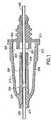
- this embodimentis directed to a needle assembly 210 with a housing 212 having a fluid inlet end 214, a fluid outlet end 216 and a frustum-shaped exterior wall 218 extending between the ends. Exterior wall 218 defines the housing interior 220.
- Housing 212further includes a cylindrical interior wall 224 that extends in the housing interior 220 from fluid inlet end 214 substantially concentrically with cylindrical exterior wall 218 to a vent plug 900. Cylindrical interior wall 224 and vent plug 900 define a flashback chamber 226.
- Needle assembly 210also includes a fluid inlet cannula 236 having an exterior end that defines a sharpened bevel and an interior end 244 that is mounted fixedly in fluid inlet end 214 of housing 212.
- Fluid inlet cannula 236is characterized further by a substantially cylindrical lumen extending between the ends and communicating with the interior of housing 212.
- Needle assembly 210further includes a fluid outlet cannula 252.
- Outlet cannula 252concludes a blunt interior end 254, an exterior end defining a sharpened bevel and a substantially cylindrical lumen extending between the ends. Portions of outlet cannula 252 between the ends are securely affixed in outlet end 216 of housing 212.
- Outlet cannula 252is mounted so that interior end 254 passes substantially coaxially into interior wall 224 and so that interior end 254 of outlet cannula 252 substantially aligns axially with interior end 244 of inlet cannula 236. Additionally, interior end 254 of outlet cannula 252 is spaced only a small distance from interior end 244 of inlet cannula 236. An axial gap between interior end 254 of outlet cannula 252 and interior end 244 of inlet cannula 236 that is less than 0.5mm may result in a flashback that is inconsistent.
- Cylindrical interior wall 224is dimensioned relative to outlet cannula 252 to achieve both desirable flow of blood through assembly 210 and to achieve effective flashback indication.
- cylindrical interior wall 224preferably is dimensioned to provide a radial gap around outlet cannula 252 of about 0.2mm, as indicated by dimension "c" in FIG. 1 . This gap achieves a substantially laminar blood flow within flashback chamber 226 and prevents blood hemolysis.
- the small radial gap between cylindrical inner wall 224 and outlet cannula 252enables a drop of blood to be spread thinly across the radial gap in flashback chamber 226 to provide a magnified flashback indication with a very small volume of blood.
- an easily visualized flashback indicationis achieved quickly at the first appearance of blood from interior end 244 of inlet cannula 236.
- Needle assembly 210further includes a sealable sleeve 261 mounted to fluid outlet end 216 of housing 212 and covering exterior end 258 of outlet cannula 252 when sealable sleeve 261 is in an unbiased condition.
- sealable sleeve 261can be collapsed in response to pressure exerted by the stopper of an evacuated tube for urging exterior end 260 of outlet cannula 252 through both sealable sleeve 261 and stopper of an evacuated tube, as known in the art.
- the above embodimentis described in terms of a vent plug.
- the vent mechanismmay be, for example, a porous vent plug formed from a matrix or carrier material, typically hydrophobic, that is coated with, impregnated with, or otherwise, contains a hydrophilic material that swells on contact with aqueous or water containing substances.
- the hydrophobic carrier materialcan be but is not limited too, high-density polyethylene, polytetrafluoroethylene, ultra-high molecular weight polyethylene, Nylon 6, polypropylene, polyvinylidine fluoride and polyethersulfone. The swellable nature of the hydrophilic material thereby provides the sealing function in the vent upon contact with blood.
- a porous vent plugthat becomes sealed upon contact with blood using biological phenomena, e.g., by clotting and/or cell agglutination that blocks the vent; a superabsorbant material to seal the vent by swelling on contact with an aqueous fluid; or a one-way valve, (e.g., a thin flap such as plastic film covering a vent, a deformable seal such as a rubber or plastic duckbill valve, or a deformable wrap over a vent). It should be noted that any combination of these various mechanisms is also possible.
- FIGS 2-4show embodiments with varying vent plugs.
- FIG. 2shows a vent plug 900a, which is located at the end of the cylindrical inner wall 224a and fitted into a recess 301 in the housing interior non-patient wall 300.
- FIG. 3shows a vent plug in a similar location to that of FIG. 2 , however, vent plug 900b has a shoulder 901b.
- FIG. 4shows a vent plug 900c that is located both within the cylindrical inner wall 224c and the recess 301 in the housing interior non-patient wall 300, and has a shoulder 901c.
- the vent plug location in each of these embodimentsis such that no air can flow out of the flashback chamber 226 into the housing interior 220 without passing through the vent mechanism ( 900 a, b, c ).
- FIGS. 5 and 6provide schematic representations of the needle assembly 210 of FIG. 1 before and after a conventional venipuncture, in which, the needle assembly 210 is connected to a holder (not shown) and punctures the patient's skin to make a vein entry.
- the needle assembly 210Upon vein entry, blood enters the IV cannula 236 and flows toward the flashback chamber 226.
- the bloodflows from inlet cannula 236 into the space between inlet and outlet cannula, such that blood flows both into the outlet cannula 252 and into flashback chamber 226.
- flashback chamber 226indicates successful vein entry and reduces the volume of air present in housing 212 shown in FIG. 6 .
- an evacuated container(not shown), is then inserted into the holder such that exterior end 260 of second cannula 252 penetrates the stopper of the container, as known in the art.
- second cannula 252Upon penetration of the stopper by second cannula 252, a negative pressure gradient is transmitted to chamber 226, causing blood to flow from chamber 226 into the container.
- the needle assemblies described abovedesirably should be small for convenient use, but should be constructed to ensure reliable and rapid flashback.
- FIGS. 5 and 6provide schematic representations of the needle assembly 210 of FIG. 1 for purposes of depicting the application of the ideal gas law.
- Aidentifies the volume of lumen 248 through inlet cannula 236.
- Bdenotes the total volume of the housing interior 220, flashback chamber 226, lumen 242 through outlet cannula 252 and sealable sleeve 261.
- P 1is the pressure within needle assembly 210 before use, and hence substantially equals atmospheric pressure. Atmospheric pressure will vary slightly from time to time and from location to location.
- atmospheric pressure P 1will be assumed to be 760mm Hg.
- P 2 in the preceding equationis the volume of the dead space in needle assembly 210 after vein entry. More particularly, after vein entry, blood will fill lumen 248 of inlet cannula 236, thereby reducing the volume to be occupied by gas in remaining portions of needle assembly 210 and hence increasing the pressure of air in the remaining portion of needle assembly 210.
- a needle assembly with dimensions approximately as shown in FIG. 1will have a pressure P 2 of about 790mm Hg at venous pressure (with tourniquet).
- V 1 in the preceding equationdefines the volume of the total dead spaced in needle assembly 210 before use, and hence will equal A + B as shown in FIG. 5 .
- V 2defines the dead space in the device after vein entry, and with lumen 248 of inlet cannula 236 filled with blood. Hence, V 2 in the preceding equation will equal B.
- dead space in housing 212, outlet cannula 252 and sleeve 261advantageously is at least 25.3 times the volume defined by lumen 248 through inlet cannula 236, and most advantageously is about 26 times the volume of lumen 248.
- other configurationsare possible and will function as described herein.
- outlet cannula 252The immediate response when an evacuated tube is placed in communication with outlet cannula 252 is to draw blood from the vein into tube (not shown).
- the highest-pressure gradientis always maintained between the vein and the evacuated tube.
- vent plug 900inhibits the pressurized air within housing interior 220 from then moving into the flashback chamber 226 and into the inlet cannula 236, which could promote dripping of blood from the IV cannula tip.
- FIG. 7schematically shows a needle assembly 310 with a housing 312 that is substantially identical to housing 212 described and illustrated above.
- Needle assembly 310differs from needle assembly 210 in that a single double end needle cannula 336 is provided and passes entirely through housing 312, More particularly, needle cannula 336 includes a venous entry end 338, a non-patient end 340 and a lumen 342 extending therebetween. Portions of cannula 336 within inner wall 324 include a slot or aperture 344 to provide communication between lumen 342 and flashback chamber 336 within inner wall 324. Needle assembly 310 functions substantially in the same manner as needle assembly 210 described and illustrated above.
- FIGS. 8-11depict a needle assembly in yet an embodiment of the invention.
- the housing interiorincludes a vent plug 900, which seals the flashback chamber 226/326 from the housing interior 220/320.
- the vent plugis described as sealing upon flow of blood into the flashback chamber, thereby inhibiting any pressurized air that may build up within the housing chamber 220/320 (such as upon displacement of air from the flashback chamber 226/326 into the housing chamber 220/320 during the initial flash procedure) from moving in a reverse direction toward the inlet cannula.
- a porous ventis positioned within the housing at a location such that the vent divides the housing into two chambers having sizes and dimensions to establish predetermined volumes thereto. Moreover, the porous vent remains porous to blood and does not seal upon contact with blood. Desirably the blood does not contact the porous vent at the initial flash indication, but such contact occurs at a later point during use of the assembly, as will be described in more detail herein.
- FIGS. 8-11show a needle assembly 410 similar to that described in connection with FIG. 1-6 above.
- needle assembly 410includes a housing 412 having a fluid inlet end or first end 414 and a fluid outlet end or second end 416.
- Needle assembly 410includes exterior wall 418 defining the housing interior. Exterior wall 418 extends generally longitudinally at the first end 414 forming an elongate longitudinal first portion 419 having a first diameter. At second end 416, exterior wall 418 forms a second portion 421 that has a second diameter that is generally larger than the first diameter of the first portion 419.
- housing 412may form a structure having a generally T-shaped cross-section.
- the exterior wall 418 at second end 416may be a separate element 428 that is attachable to main body portion 430 forming housing 412, thereby assisting in manufacture and assembly of needle assembly 410.
- First portion 419 and second portion 421may be arranged relative to each other in a variety of arrangements, so long as they are capable of functioning for transport of air therebetween as discussed herein.
- Needle assembly 410further includes a fluid inlet cannula 436 extending from first end 414 of housing 412.
- Fluid inlet cannula 436includes an exterior end that defines a first puncture tip such as a sharpened bevel at patient puncture tip 438, and extends within first end 414 of housing 412 at open end 429, and may be fixedly mounted therein.
- Fluid inlet cannula 436is characterized further by a substantially cylindrical lumen extending between the ends and communicating with the interior of housing 412.
- Needle assembly 410also includes a second puncture tip such as non-patient puncture tip 462 extending from second end 416 of housing 412. As seen in FIG. 10 , this may be accomplished by providing needle assembly 410 with a second cannula in the form of fluid outlet cannula 452. In particular, the end of fluid outlet cannula 452 may define a sharpened bevel forming non-patient puncture tip 462. Fluid outlet cannula 452 extends within second end 416 of housing 412, and may be fixedly mounted therein. Fluid outlet cannula 452 is characterized further by a substantially cylindrical lumen communicating with the interior of housing 412.
- Outlet cannula 452is mounted within housing 412 so that an interior end 464 passes substantially coaxially therein such that outlet cannula 452 substantially aligns axially with the interior end of inlet cannula 436. Desirably, this is achieved by mounting outlet cannula 452 at a location adjacent second end 416 of housing 412, such that the interior end 464 of outlet cannula 452 extends within housing 412 to a location adjacent the interior end 439 of inlet cannula 436. As seen in FIG.
- the interior end 464 of outlet cannula 452is spaced only a small distance from the interior end 439 of inlet cannula 436, thereby forming an axial gap therebetween for flow of blood into flashback chamber 426 about outlet cannula 452.
- the distance between the interior end 464 of outlet cannula 452 and the interior end 439 of inlet cannula 436 forming the axial gapis sufficient to provide for flow of blood into flashback chamber 426 based upon the patient's blood pressure after venipuncture.
- an axial gap that is less than 0.5mmmay result in a flashback that is inconsistent.
- fluid inlet cannula. 436 and fluid outlet cannula 452are positioned and dimensioned within housing 412 so as to achieve both desirable flow of blood through assembly 410 and to achieve effective flashback indication.
- wall 418 of housing 412is dimensioned to provide a radial gap around outlet cannula 452 of about 0.2mm at an area surrounding the internal end 464 thereof This gap achieves a substantially laminar blood flow within flashback chamber 426 and prevents blood hemolysis.
- the small radial gap between the inner surface of wall 418 and outlet cannula 452 at the area surrounding the internal end 464enables a drop of blood to be spread thinly across the radial gap in flashback chamber 426 to provide a magnified flashback indication with a very small volume of blood.
- an easily visualized flashback indicationis achieved quickly at the first appearance of blood within flashback chamber 426.
- internal end 464 of outlet cannula 452may be partially supported within housing 412, so long as blood flow into flashback chamber 426 is achieved about the internal end 464.
- a single cannulais provided, similar to that embodiment discussed in connection with FIG. 7 .
- Such an arrangementis depicted in the embodiment of FIG. 12A and 12B (shown in connection with a blood collection assembly as will be described in more detail herein).
- the fluid inlet cannula and the fluid outlet cannularepresent one single cannula 470, having a patient puncture tip 438 a non-patient puncture tip 462, and a lumen 442 extending therethrough, and with the body of the cannula 470 being fixedly attached to a portion of the housing 412 and passing entirely through housing 412.
- a portion of cannula 470 extending through housing 412includes one or more openings such as a slot or aperture 444 to provide communication between lumen 442 and flashback chamber 436 within housing 412.
- openingssuch as a slot or aperture 444 to provide communication between lumen 442 and flashback chamber 436 within housing 412.
- FIGS. 12A and 12Btwo separate apertures are shown on opposing sides of cannula 470, although it is contemplated that any number of such openings can be included to provide for blood flow into flashback chamber 436.
- needle assembly 410further includes a sealable sleeve 461 mounted to fluid outlet end 416 of housing 412. This may be accomplished by providing a mounting protrusion 429 at second end 416 of housing 412, such as on element 428, with sealable sleeve 461 representing an elastomeric element that can be frictionally fit or otherwise affixed over protrusion 429. Sealable sleeve 461 covers non-patient puncture tip 462 at the exterior end of outlet cannula 452 when sealable sleeve 461 is in an unbiased condition.
- sealable sleeve 461can be collapsed in response to pressure exerted by the stopper of an evacuated tube for urging exterior end 460 of outlet cannula 452 through both sealable sleeve 461 and the stopper of an evacuated tube, as known in the art.
- FIGS. 8-11further includes a porous vent 910 positioned within the interior of housing 412.
- Porous vent 910is positioned within housing 412 to divide housing 412 into two distinct chambers, namely, a first chamber represented by flashback chamber 426 and a second chamber represented by secondary chamber 427.
- Porous vent 910may be constructed of a suitable material as described above with respect to vent plug 900, albeit without the hydrophilic material that swells on contact.
- porous vent 910is adapted to vent air therethough, and represents a porous structure including a plurality of pores that allow for passage of blood therethrough without sealing from fluid flow therethrough upon contact with blood, as is known in the art with vent plugs including a hydrophilic material.
- porous vent 910at least partially fill with blood due to the negative pressure established within secondary chamber 427.
- Such filled poresin combination with the negative pressure within secondary chamber 427 prevent air flow between the secondary chamber 427 and the flashback chamber 426, and provide for fluid resistance of the blood flow through porous vent 910, as will be described in further detail.
- porous vent 910is positioned within the interior of housing 412 between first portion 419 and second portion 421.
- first portion 419 of housing 412essentially defines the flashback chamber 426
- second portion 421 of housing 412essentially defines the secondary chamber 427.
- porous vent 910may be positioned within the interior of housing 412 at a location spanning the transition between the first diameter of first portion 419 and the second diameter of second portion 421, as shown in the embodiment of FIGS. 12A and 12B .
- porous vent 910is generally a cylindrically-shaped member with a central opening therein axially encircling a portion of the cannula, particularly fluid outlet cannula 452.
- the interior volume of housing 412is defined by the sum of the volumes of flashback chamber 426 and secondary chamber 427 as well as the volume represented by the pores of porous vent 910.
- Such interior volumeis configured so as to provide for certain attributes to the needle assembly 410, in particular with respect to the ability of the secondary chamber 427 to be at least partially evacuated of a portion of the air therein to establish a negative pressure therein upon application of an evacuated tube to needle assembly 410 during use thereof.
- Such negative pressure within secondary chamber 427draws blood through the pores of porous vent 910 based on when blood contacts porous vent 910 and partially fills the pores thereof.
- the overall interior volume of housing 412may be from about 300 mm 3 to about 400 mm 3 .
- Such a volumeis particularly useful for the intended use of needle assembly 410 for conventional venipuncture for drawing a blood sample from a patient using a needle cannula having a conventional gauge for venipuncture as is known in the art.
- Such a volumealso enables the needle assembly to be particularly useful with patients having relatively low blood pressure, in that the interior volume of the housing 412 is sufficient so as to prevent a significant amount of positive pressure build up within the interior volume space during initial venipuncture.
- Porous vent 910is desirably positioned within housing interior so as to define flashback chamber 426 as having a volume that represents from about 5 percent to about 20 percent of the total overall volume of housing 412, desirably from about 7 percent to about 12 percent of the total overall volume of housing 412, including the volume of secondary chamber 427 and the volume of the pores within porous vent 910.
- the remaining internal volume of housing 412defined by the internal volume positioned downstream from the interface between porous vent 910 and flashback chamber 426 including the internal pores of porous vent 910 and the volume of secondary chamber 427, represents a significant portion of the internal volume of housing 412.
- Such a ratio of the flashback chamber 426 to the total overall volume of the housing 412assures that flashback chamber 426 has sufficient volume to properly visualize the initial flash, desirably while preventing blood from fully contacting the porous vent 910 at initial venipuncture, based on the initial build-up of pressure within secondary chamber 427 caused by venous pressure forcing the blood into flashback chamber 426.
- Such volume ratiosare effective for the intended use as described in further detail herein, wherein blood flowing into flashback chamber 426 upon initial venipuncture does not fully contact porous vent 910, and desirably does not contact porous vent 910, and wherein at least a portion of the air is drawn out from secondary chamber 427 based upon application of an evacuated blood collection tube to the needle assembly 410.
- secondary chamber 427can effectively draw blood from within flashback chamber 426 and from within fluid inlet cannula 426 toward secondary chamber 427, such as into and through the pores of porous vent 910, when patient puncture tip 438 is removed from the patient and is exposed to the external environment.
- the total interior volume of the housing 412is about 380 mm 3 , with the flashback chamber 426 having a volume of about 30 mm 3 , the secondary chamber 427 having a volume of about 300 mm 3 , and the pores of the porous vent 910 representing a volume of about 50 mm 3 .
- Needle assembly 410may be assembled as follows. Fluid inlet cannula 436 is positioned through first end 414 of housing 412 such that the open interior end 439 is positioned within an interior portion of housing 412 at first portion 419 and patient puncture tip 438 extends externally of first end 414. Fluid outlet cannula 452 is positioned within housing 412 through the opposite end, such that open internal end 464 is positioned within an interior portion of housing 412 at first portion 419 adjacent interior end 439 of fluid inlet cannula 436, with a slight gap therebetween, and with non-patient puncture tip extending externally of second end 416. Fluid inlet cannula 436 and fluid outlet cannula 452 may be affixed therein in any known manner, desirably through a medical grade adhesive.
- such cannula 470is affixed within housing 412 such that opening 472 is positioned within the interior of housing 412 at first portion 419, with patient puncture tip 438 extending externally of first end 414 and non-patient puncture tip 462 extending externally of second end 416.
- Porous vent 910is then inserted within housing 412 and positioned over fluid outlet cannula 454 (or over the single cannula 470 ), and element 428 is thereafter affixed to the second end 416, enclosing the interior of housing 412. Sealable sleeve 461 is then affixed over protrusion 429. As such, the interior of housing 412 is closed from the external environment, with the sole path for fluid communication between the interior of housing 412 and the external environment being provided through the patient puncture tip 438.
- Needle assembly 410 assembled as suchcan be used in connection with a blood collection tube holder 800, as depicted in the embodiment shown in FIG. 12 . Such assembly may be accomplished through the rear open end of blood collection tube holder 800, so that the entire needle assembly 410 is inserted to a portion where at least patient puncture tip 438 and at least a portion of inlet cannula 436 extend out through the front end of blood collection tube holder 800.
- second portion 421 of needle assembly 410is radially larger than first portion 419, such an insertion and arrangement enables the secondary chamber 427 to be fully contained within the internal space within collection tube holder 800, and with flashback chamber 426 extending out from a front end thereof
- needle assembly 410may be provided with collection tube holder 800 attached thereto.
- Patient puncture tip 438is inserted through the skin of a patient and into the patient's vasculature, desirably into a vein.
- housing 412is an entirely closed structure, and since sealable sleeve 461 closes off the only outlet of housing 412 ( i.e ., fluid outlet cannula 452 ).
- the patient's blood pressurecauses blood to flow through patient puncture tip 438, into fluid inlet cannula 436, and out interior end 439 (or through opening 472 in the embodiment of FIG. 12 ), into flashback chamber 426 surrounding interior end 464 of outlet cannula 452.
- the transparent or translucent nature of housing 412permits visualization of the blood within flashback chamber 426, providing an indication that venipuncture is achieved.
- Flashback chamber 426 and secondary chamber 427are configured through their size and dimensions such that the volumes thereof permit blood to flow into flashback chamber 426 at this initial venipucture, but the build up of air pressure within the pores of porous vent 910 and within secondary chamber 427 prevents blood from fully contacting porous vent 910, and desirably prevents blood from even partially contacting porous vent 910 at the initial venipuncture.
- a sample collection container having a negative pressure thereinsuch as an evacuated blood collection tube (not shown) as is commonly known in the art, is inserted within the tube holder 800.
- the stopper (not shown) of such evacuated containercontacts and displaces sealable sleeve 461, causing non-patient puncture tip 462 to puncture through sealable sleeve 461 and through the stopper of the evacuated container.
- fluid communicationis established between the non-patient puncture tip 462 and the interior of the evacuated collection container.
- the negative pressure within the evacuated collection containerdraws the blood that has collected within flashback chamber 426 into fluid outlet cannula 452 and into the evacuated collection container.
- the negative pressure within the evacuated collection containerwill also draw at least a portion of the air out of the flashback chamber 426 and out of the secondary chamber 427 through the pores of porous vent 910, toward and into the evacuated collection container.
- the close proximity and alignment of fluid outlet cannula 452 and fluid inlet cannula 426causes blood to be drawn from fluid inlet cannula 436 and from the patient, simultaneously with such air being drawn from the flashback chamber 426 and secondary chamber 427.
- Such drawing of airreduces the pressure within the flashback chamber 426 and the secondary chamber 427, establishing a negative pressure therein with respect to the patient's bloodstream and with respect to the external environment.
- This negative pressurethat has been established within the interior of housing 412, and specifically within flashback chamber 426 and secondary chamber 427, draws additional blood from within fluid inlet cannula 436 and from the patient into flashback chamber 426, with the blood contacting porous vent 910.
- the bloodWith such blood filling flashback chamber 426, the blood fully contacts the surface of porous vent 910 that extends within flashback chamber 426, and begins to fill the pores of porous vent 910.
- Such filling of the pores of porous vent 910 that are directly at the interface of porous vent 910 and flashback chamber 426closes off the porous vent from airflow therethrough, but does not fully act as a seal, in that the blood does not cause the material of the porous vent to swell or close off to air flow, but instead merely physically fills the voids within the porous vent.
- secondary chamber 427represents a closed chamber with a negative pressure therein relative to the external environment.
- Secondary chamber 427Since the volume of secondary chamber 427 represents a substantial portion of the overall interior volume of housing 412, a significant portion of interior volume of housing 412 downstream of the filled pores at the interface of porous vent 910 and flashback chamber 426 remains at a negative pressure with respect to the remainder of the interior volume. Secondary chamber 427 will therefore continue to have a drawing effect on the blood within the pores of porous vent 910 and within flashback chamber 426 through the pores of porous vent 910 toward secondary chamber 427, without releasing any air from the secondary chamber 427 in the opposite direction due to the pores of porous vent 910 at the interface of the flashback chamber 426 being filled with blood, thereby effectively preventing air flow through porous vent 910 due to the filled pores.
- the draw created by the negative pressure within secondary chamber 427has a fluid resistance based on the blood filling the pores of porous vent 910 and based on the tortuous path created by the pores of porous vent 910, and therefore is a gradual draw with reduced fluid movement.
- the evacuated collection container and the secondary chamber 427are both at a negative pressure with respect to the external environment (and with respect to the patient's bloodstream), and therefore both effect a draw from the fluid inlet cannula 436.
- This mutual drawing effectmay essentially establish an equilibrium within the flashback chamber 426, such that the blood contained within the flashback chamber 426 is not drawn toward or into either the secondary chamber 427 through the pores of porous vent 910 or into the evacuated collection container through the fluid inlet cannula 436, but instead essentially remains within flashback chamber 426 in a steady state.
- the negative pressure of the evacuated collection containerdraws blood directly from the patient through fluid inlet cannula 436, due to the close proximity and alignment of fluid outlet cannula 452 and fluid inlet cannula 426, as well as due to the equilibrium established within flashback chamber 426 (based on the opposite draw forces between the evacuated collection container and the evacuated secondary chamber 427 ).
- the continual draw of blood into the evacuated collection containergradually causes the pressure within the collection container to increase.
- the containeris removed from the non-patient puncture tip 462, thereby releasing the fluid communication between the non-patient puncture tip 462 and the evacuated collection container, with sealable sleeve 461 then covering and closing off non-patient puncture tip 462. Absent such draw from the negative pressure of the evacuated collection tube, the negative pressure within the secondary chamber 427 effects a slight draw on the blood within flashback chamber 426 through the pores of porous vent 910. Such draw, however, is slow and gradual, due to the tortuous path of blood flow through the pores of porous vent 910.
- Additional evacuated collection containerscan thereafter be inserted into tube holder 800 and used for sample collection through non-patient puncture tip 462 as described above, by placing a second evacuated collection container within the holder 800 and establishing fluid communication between the non-patient puncture tip 462 and the interior of the evacuated collection container by puncturing the stopper, as discussed.
- the evacuated collection container and the secondary chamber 427are both at a negative pressure, and therefore both effect a draw from the fluid inlet cannula. As above, this effect essentially establishes an equilibrium within the flashback chamber 426, thereby preventing the blood contained within the flashback chamber 426 from being drawn toward or into either the secondary chamber 427 (through the porous vent 910 ).
- the negative pressure of the evacuated collection containerdraws blood directly from the patient through fluid inlet cannula 436 as discussed above, due to the close proximity and alignment of fluid outlet cannula 452 and fluid inlet cannula 426.
- the containeris removed from the non-patient puncture tip 462, thereby releasing the fluid communication between the non-patient puncture tip 462 and the evacuated collection container, with sealable sleeve 461 then covering and closing off non-patient puncture tip 462.
- patient puncture tip 438is removed from the vasculature of the patient (i.e., from the bloodstream), thereby exposing the opening of patient puncture tip 438 to the external environment. Since the sole communication path between the housing interior and the external environment is through patient puncture tip 438, the negative pressure established within secondary chamber 427 relative to the external environment will affect a gradual draw on the blood contained within flashback chamber 426 and within fluid inlet cannula 436 toward and through porous vent 910.
- Such drawing effectwill displace and move any blood contained within fluid inlet cannula 436 away from patient puncture tip 438, toward secondary chamber 427, thereby preventing any blood from leaking from patient puncture tip 438 out of fluid inlet cannula 436.
- Such negative pressure within secondary chamber 427may continue to have a gradual drawing effect through the porous vent 910 for a prolonged period of time after removal of patient puncture tip 438 from the patient, and may draw all of the remaining blood contained within fluid inlet cannula 436 and flashback chamber 426 through porous vent 910 and/or into secondary chamber 427. Needle assembly 410 can then be properly disposed of in known manner.
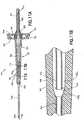
- FIGS. 13A , 13B, and 13Cdepict yet a further embodiment of a needle assembly.
- the needle assembly shown in FIGS. 13A-13Cis similar to the embodiment described above in connection with FIGS. 8-11 , albeit with the secondary chamber further comprising a plurality of interior regions that are in fluid communication with each other, and desirably gas venting fluid communication, to define the interior volume of the secondary chamber.
- needle assembly 510includes a housing 512 having a fluid inlet end or first end 514 and a fluid outlet end or second end 516. Needle assembly 510 further includes a fluid inlet cannula 536 extending from first end 514 of housing 512. Fluid inlet cannula 536 extends between an exterior end that defines a first puncture tip such as a sharpened bevel at patient puncture tip 538, and an interior open end 529 extending within first end 514 of housing 512, and may be fixedly mounted therein. Fluid inlet cannula 536 is characterized further by a substantially cylindrical lumen extending between the ends and communicating with the interior of housing 512.
- Needle assembly 510also includes a second puncture tip such as non-patient puncture tip extending from second end 516 of housing 512, such as through a second cannula in the form of fluid outlet cannula 552.
- a second puncture tipsuch as non-patient puncture tip extending from second end 516 of housing 512, such as through a second cannula in the form of fluid outlet cannula 552.
- the end of fluid outlet cannula 552may define a sharpened bevel forming non-patient puncture tip 562.
- Fluid outlet cannula 552extends within second end 516 of housing 512, and may be fixedly mounted therein. Fluid outlet cannula 552 is characterized further by a substantially cylindrical lumen communicating with the interior of housing 512.
- Outlet cannula 552is mounted within housing 512 so that an interior end 564 passes substantially coaxially therein such that outlet cannula 552 substantially aligns axially with the interior end of inlet cannula 536, in a similar manner as discussed in connection with the embodiment depicted in FIGS. 8-11 described. above.
- the interior end 564 of outlet cannula 552may be spaced only a small distance from the interior end 539 of inlet cannula 536, thereby forming an axial gap therebetween for flow of blood into flashback chamber 526 about outlet cannula 552 as shown in FIG. 13C , or may be a single cannula having an opening therein, as described in connection with the embodiment of FIGS. 12A-12B .
- needle assembly 510includes a generally elongate longitudinal portion at first end 514, which generally includes an interior wall 515 and an exterior wall 517.
- Interior wall 515extends generally longitudinally within housing 512, with a first diameter defining an interior chamber in the form of flashback chamber 526.
- Second end 516defines a second portion having a second diameter that is generally larger than the first diameter of interior wall 515.
- Interior wall 515is dimensioned to provide a radial gap around outlet cannula 552 of about 0.2 mm at an area surrounding the internal end 564 thereof, thereby achieving a substantially laminar blood flow within flashback chamber 526, as discussed above.
- Needle assembly 510may further include a sealable sleeve 561 mounted to fluid outlet end 516 of housing 512, such as through a mounting protrusion 529, as discussed above.
- needle assembly 510further includes a porous vent 910a positioned within the interior of housing 512.
- Porous vent 910ais generally a cylindrically-shaped member with a central opening therein axially spaced from and encircling a portion of the cannula, particularly fluid outlet cannula 452.
- Porous vent 910amay be constructed of any suitable material as described above in connection with the embodiment of FIGS. 8-11 .
- Porous vent 910ais positioned within housing 512 in a manner such that housing 512 is divided into at least two distinct chambers, namely, a first chamber represented by flashback chamber 526 and a second chamber, representing the total internal volume of housing 512 that is positioned downstream of porous vent 910a.
- downstreamis used herein to represent location with respect to the intended flow of blood through the housing 512 of needle assembly 510, i.e., blood flows through housing 512 from patient puncture tip 538 at fluid inlet cannula 536, through open end 539, into flashback chamber 526, into porous vent 910a, and toward the secondary chamber.
- Porous vent 910amay be positioned within the interior of housing 512 at a location spanning the transition between the first end 514 and the second end 516.
- the interior volume of housing 512is defined by the sum of the volumes of the flashback chamber and the secondary chamber as well as the volume represented by the pores of porous vent 910a.
- Such interior volumeis configured so as to provide for certain attributes to the needle assembly 510, in particular with respect to the ability of the secondary chamber to be at least partially evacuated of a portion of the air therein to establish a negative pressure therein upon application of an evacuated tube to needle assembly 510 during use thereof, as described in connection with the embodiments set forth above.
- Such negative pressure within the secondary chamberdraws blood into the pores of porous vent 910a based on when blood contacts porous vent 910a at the interface between the porous vent 910a and flashback chamber 526 and partially fills the pores thereof
- the secondary chambercomprises a plurality of distinct interior regions, such as a first interior region 527a and a second interior region 527b.
- the secondary chamber 427represents a radially enlarged portion at the second end 416 of housing 412, which enlarged portion accommodates the proper size of porous vent 910 and the proper internal volume required for secondary chamber 427 to function in the intended manner ( i.e ., to represent a substantial volume of the total interior volume of housing 512 so as to be able to establish a negative pressure therein during use, as described above).
- the secondary chambermay extend longitudinally along the housing 510. It is important, however, to ensure that sufficient surface area exists between the secondary chamber and the pores of porous vent 910a in order to ensure a sufficient drawing effect once the secondary chamber is evacuated in its intended use. Accordingly, the secondary chamber may be divided into a plurality of regions, such as in the embodiment of FIGS. 13A-13C , in which the secondary chamber includes first interior region 527a and second interior region 527b, with first and second interior regions 527a, 527b in fluid communication with each other through porous vent 910a, and also in fluid communication with respect to flashback chamber 526 downstream of flashback chamber 526.
- the total volume of the secondary chamber downstream of the flashback chamberwhich is made up of a plurality of interior regions separated by the porous vent, is sufficient to achieve the intended use of the device as described herein, by maintaining the secondary chamber as a significant amount of the total volume of the needle housing.
- the number of interior regionscan be any number, so long as the total interior volume of the secondary chamber (represented by the total volume of the combined interior regions positioned downstream of porous vent 910a ), define a downstream secondary chamber volume corresponding to the volume and ratios described above with respect to the embodiment of FIGS. 8-11 .
- First interior region 527a of the secondary chambermay generally be located adjacent the second end 516 of housing 512, while second interior region 527b of the secondary chamber may be positioned generally concentric about a portion of the flashback chamber 526.
- housing 512as a two-part housing, with first end 514 representing a main body portion 530 of the housing, and second end 516 representing a separate body portion 528 of the housing that is attachable to the main body portion 530, forming housing 512.
- main body portion 530 of the housingmay include interior wall 515 defining flashback chamber 526 and exterior wall 517 defining second interior region 527b.
- Main body portion 520extends generally along the axis defining needle assembly 510 to define an elongate longitudinal portion, with interior wall 515 defining a first diameter for flashback chamber 526, and exterior wall 517 defining a second diameter for second interior region 527b.
- the exterior wall of separate body portion 528 at second end 516 of housing 512generally defines the first interior region 527a
- exterior wall 517 of main body portion 530 of housing 512generally defines second interior region 527b.
- second interior region 527bextends distally from the porous vent 910 longitudinally and annularly surrounding a portion of flashback chamber 526.
- both interior wall 515 and exterior wall 517are transparent or translucent, such that the contents of flashback chamber 526 (such as blood flow therein) can be viewable through the second interior region 527b and/or through the first interior region 527a.
- Exterior wall 517 of housing 512may generally taper from a larger diameter to a smaller diameter toward first end 514.
- a portion of exterior wall 517 shown in FIG. 13B at portion 517pmay include a substantially constant diameter for accommodating porous vent 910a therein in a tightly sealed arrangement.
- porous vent 910amay include dimensions that taper to coincide with the interior wall surface along tapering exterior wall 517.
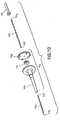
- FIGS. 14-16depict a further embodiment, in which needle assembly 510 is shown in use in connection with a safety blood collection set, including tube holder 810 for accommodating an evacuated blood collection tube (not shown) during a standard blood collection procedure in known manner, and a pivoting safety shield 812 for protecting the needle after use of the blood collection set.
- a safety blood collection setincluding tube holder 810 for accommodating an evacuated blood collection tube (not shown) during a standard blood collection procedure in known manner, and a pivoting safety shield 812 for protecting the needle after use of the blood collection set.
- needle assembly 510works in substantially the same manner as needle assembly 410 described above in connection with FIGS. 8-12 , with first and second interior regions 527a, 527b acting in the same manner as secondary chamber 427 described in the prior embodiment.
- needle assembly 510is provided in combination with a tube holder, such as tube holder 810.
- a tube holdersuch as tube holder 810.
- bloodflows into fluid inlet cannula 536 based on blood pressure of the patient and out the open end 539 thereof, into flashback chamber 526 for visualization of blood flow, but does not fully contact the pores of porous vent 910a.
- an evacuated blood collection containeris inserted into tube holder 810 for piercing by the non-patient puncture tip 562 of fluid outlet cannula 552, which draws blood out from flashback chamber 526 and draws air out from first and second interior regions 527a, 527b, thereby reducing the pressure within flashback chamber 526 and first and second interior regions 527a, 527b, in a manner as described above.
- first and second interior regions 527a, 527bdraw blood from the patient through fluid inlet cannula 536, fully contacting the surface of porous vent 910a at the interface between porous vent 910a and flashback chamber 526 to fill the pores thereof Since the interior volume within first and second interior regions 527a, 527b has been evacuated, first and second interior regions 527a, 527b represent a closed environment with a negative pressure therein, and therefore continue to have a drawing effect on the blood within the filled pores of porous vent 910a and within flashback chamber 526, as discussed above.
- first and second interior regions 527a, 527bdue to the filled pores of porous vent 910a sealing off first and second interior regions 527a, 527b from the external environment, and such negative pressure within first and second interior regions 527a, 527b continues to affect a gradual draw on the blood contained within the pores of porous vent 910a and flashback chamber 526 and within fluid inlet cannula 536 away from patient puncture tip 538, thereby preventing any blood from leaking from patient puncture tip 538.
- continual drawmay cause blood to flow completely through the pores of porous vent 910a and into one or both of first and second interior regions 527a, 527b.
Landscapes
- Health & Medical Sciences (AREA)
- Life Sciences & Earth Sciences (AREA)
- Engineering & Computer Science (AREA)
- Molecular Biology (AREA)
- Animal Behavior & Ethology (AREA)
- Pathology (AREA)
- Physics & Mathematics (AREA)
- Biomedical Technology (AREA)
- Heart & Thoracic Surgery (AREA)
- Medical Informatics (AREA)
- Hematology (AREA)
- Surgery (AREA)
- Biophysics (AREA)
- General Health & Medical Sciences (AREA)
- Public Health (AREA)
- Veterinary Medicine (AREA)
- Vascular Medicine (AREA)
- Manufacturing & Machinery (AREA)
- Measurement Of The Respiration, Hearing Ability, Form, And Blood Characteristics Of Living Organisms (AREA)
- Media Introduction/Drainage Providing Device (AREA)
Description
- The present invention relates to a device for collecting blood samples by performing venipuncture on a patient. More particularly, the present invention relates to a needle assembly for multiple sample blood collection that allows a phlebotomist to determine whether vein entry has occurred when collecting a blood sample from a patient into an evacuated blood collection tube.
- Venipuncture is the primary method used for acquiring blood samples for laboratory testing. In performing venipuncture procedures, a phlebotomist must follow several steps simultaneously. Such steps include assessing the patient's overall physical and psychological condition so as to properly select a venipuncture site and technique. The phlebotomist must also select the proper corresponding equipment, perform the technique so as to control bleeding, and properly collect and identify fluid specimens for testing. The phlebotomist must ascertain all of these coinciding factors, as such factors may adversely affect the distension of the vein and the length of the venipuncture procedure.
- Various venipuncture devices have been developed to address the above-described problems. These devices include products intended to assist the phlebotomist in confirming that vein entry has been made seee.g., United States. Patent Nos.
5,222,502 and5,303,713 . Such a device contains a needle assembly with a housing that defines a chamber therein. A single cannula pointed at both ends is affixed to the housing. The intravenous (IV) end of the cannula is adapted for penetration of a patient's vein. The non-patient end of the cannula has a sealable sleeve and is adapted for penetration of a penetrable stop positioned within an evacuated container. - Upon vein entry with the intravenous end of the cannula, blood will flow through the cannula, into the sealable sleeve and into the housing chamber, which is clear or translucent for visualization ("flashback"). Once air is vented from the flashback chamber, the blood therein is pressurized each time the sealable sleeve is pushed toward the housing chamber upon activation of an evacuated container.
- Due to the length of time between vein entry and flashback, the phlebotomist may erroneously believe that satisfactory vein entry has not been achieved since there is no immediate indication of vein entry in the see-through chamber. The phlebotomist may therefore unnecessarily repeat the venipuncture procedure, requiring replacement of the evacuated container and/or the needle assembly itself. Such a repetitive process prolongs the physical and emotional discomfort endured by the patient. In such cases, a phlebotomist may use a blood collection set to provide some entry indication, and will then incur the cost of the blood collection set, as well as the cost of a discard tube.
- It would therefore be desirable to provide an improved blood collection device that permits blood flow through a relatively short needle directly into a flashback chamber, thereby providing immediate indication of successful vein entry.
WO2006/022716A discloses a needle assembly having a transparent or translucent housing with a flashback chamber and a venting mechanism.US 4,207,870 A discloses a blood sampling assembly having porous vent means.US 4,305,406 A discloses needle assemblies with anti-backflow features.- The invention provides a needle assembly for the extraction of at least one fluid sample into an evacuated container for laboratory testing. The needle assembly provides a clear or translucent housing with sufficient dead space for blood to flow into a flashback chamber for visualization by the user to confirm successful vein entry, with an internal vent mechanism.
- The invention is as defined in the appended claims.
- In one embodiment, the invention relates to a needle assembly comprising a housing defining a housing interior, a cannula having a patient puncture tip extending from a first end of the housing, and a non-patient puncture tip extending from a second end of the housing. The non-patient puncture tip and the patient puncture tip are in fluid communication with each other through the cannula, such that the sole communication path between the housing interior and the external environment is via the patient puncture tip. A porous vent is positioned within the housing interior to separate the housing interior into a first chamber and a second chamber, with the cannula being in fluid communication with the first chamber. The porous vent includes pores for passage of blood therethrough from the first chamber to the second chamber. The first chamber and the second chamber are configured such that upon insertion of the patient needle tip into a patient, blood flows through the cannula and into the first chamber without sealing the porous vent. Upon application of an evacuated container to the non-patient puncture tip, blood is drawn from the first chamber and air is drawn from the second chamber, thereby establishing a negative pressure within the second chamber with respect to an external environment of the needle assembly. Blood can thereafter be drawn into the first chamber and through the porous vent, with a negative pressure maintained in the second chamber.
- In one embodiment, the cannula includes a first end comprising the patient puncture tip and a second end comprising the non-patient puncture tip, with an opening between the first end and the second end providing fluid communication between the cannula and the first chamber of the housing. In an alternate embodiment, the cannula comprises a first cannula having a patient puncture tip, with the needle assembly further comprising a second cannula including the non-patient puncture tip, with the first cannula and the second cannula substantially axially aligned and separated by a gap in fluid communication with the first chamber of the housing. A sleeve may also extend about the non-patient puncture tip.
- In one embodiment, the second chamber may include multiple interior regions in fluid communication, such as a first interior region and a second interior region. The first and second interior regions of the second are in fluid communication with each other through the porous vent.
- In a particular embodiment, the first end of the housing comprises an elongate longitudinal first portion having a first diameter and the second end of the housing comprises a second portion having a second diameter larger than the first diameter of the first portion. In such an embodiment, the porous vent may be positioned within the housing interior between the first portion having a first diameter and the second portion having a second diameter. Alternatively, the porous vent may be positioned within the housing interior at a location spanning the transition between the first diameter of the first position and the second diameter of the second position. In embodiments where the second chamber includes multiple interior regions, such as a first interior region and a second interior region, the first chamber may extend along a portion of the longitudinal first portion, with at least one of the interior regions, such as the second interior region of the second chamber extending longitudinally concentrically about the first chamber. In this manner, the external diameter, and thus the external profile of the needle assembly, can be decreased.
- The invention can be used in a method of preventing leakage of blood from a needle assembly is provided. The method involves receiving blood through a patient puncture tip and into a first chamber of a needle assembly, with the needle assembly including a needle housing defining a housing interior; a cannula having the patient puncture tip extending from a first end of the needle housing; a non-patient puncture tip extending from a second end of the needle housing, the non-patient puncture tip and the patient puncture tip being in fluid communication with each other through the cannula; and a porous vent positioned within the housing interior and separating the housing interior into a first chamber and a second chamber. The cannula is in fluid communication with the first chamber such that the sole communication path between the housing interior and the external environment is via the patient puncture tip, and the porous vent includes pores for passage of blood therethrough from the first chamber into the second chamber. Fluid communication is established between the non-patient puncture tip and an evacuated collection container, such that blood contained within the first chamber is drawn into the evacuated collection container and air is drawn out of the second chamber through the porous vent. As such, a negative pressure is established within the second chamber relative to the external environment of the needle assembly, such that blood flows through the cannula into the first chamber and contacts the porous vent. Blood is then drawn through the pores of the porous vent toward the second chamber such that after removing the patient puncture tip from the vasculature of the patient any blood contained within the cannula is displaced away from the patient puncture tip based upon the negative pressure established within the second chamber.
- Additionally, a further step may include establishing fluid communication between the non-patient puncture tip and a second evacuated collection container prior to drawing blood through the patient puncture tip and through the cannula into the second evacuated collection container, followed by releasing the fluid communication between the non-patient puncture tip and the second evacuated collection container.
- In yet a further embodiment, the invention can be used in a method of collecting a sample of blood from a patient into an evacuated blood collection tube using a blood collection assembly having a patient needle tip and a non-patient needle tip and a housing having a flashback visualization chamber. The method involves using a needle assembly comprising a housing having a porous vent positioned therein to separate an interior of the housing into a first chamber forming the flashback visualization chamber and a second chamber, the first chamber and second chamber being configured such that air is drawn out of the second chamber through the porous vent and into the evacuated blood collection tube along with the blood sample, thereby establishing a negative pressure within the second chamber. The negative pressure causes blood to be drawn into the first chamber and contact the porous vent, such that after the patient needle tip is removed from the patient, the negative pressure within the second chamber draws blood from the patient needle tip toward the second chamber, thereby preventing leakage of blood from the patient needle tip.
FIG. 1 is a cross-sectional view of a typical embodiment of the needle assembly disclosed herein.FIG. 2 is a cross-sectional view of a second embodiment.FIG. 3 is a cross-sectional view of a third embodiment.FIG. 4 is a cross-sectional view of a fourth embodiment.FIG. 5 is a schematic view of the needle assemblyofFIG. 1 prior to use.FIG. 6 is a schematic view similar toFIG. 5 , but showing the first sign of venous entry.FIG. 7 is a schematic view of a fifth embodiment.FIG. 8 is a perspective view of a needle assembly having a flash chamber in a further embodiment.FIG. 9 is a rear perspective view of the needle assembly having a flash chamber ofFIG. 8 .FIG. 10 is an exploded view of the needle assembly having a flash chamber ofFIG. 8 .FIG. 11A is a cross-sectional view of the needle assembly having a flash chamber ofFIG. 8 .FIG. 11B is an enlarged cross-sectional view of a portion of the needle assembly ofFIG. 11A .FIG. 12A is a cross-sectional view of a needle assembly having a flash chamber used in connection with a blood collection assembly in yet a further embodiment.FIG. 12B is an enlarged sectional view of a portion of the needle assembly ofFIG. 12A .FIG. 13A is a cross-sectional view of a needle assembly having a flash chamber used in connection with a blood collection assembly in yet a further embodiment.FIG. 13B is an enlarged sectional view of a portion of the needle assembly ofFIG. 13A .FIG. 13C is an enlarged sectional view of a portion of the needle assemblyofFIG. 13B .FIG. 14 is a perspective view of the needle assembly ofFIG. 13A shown in combination with a blood collection holder, with a needle shield in a shielding position.FIG. 15 is a side view of the needle assembly ofFIG. 15 .FIG. 16 is an enlarged side sectional view of the needle assembly ofFIG. 16 .- The invention provides a needle assembly for blood collection that provides a visual indication of vein entry ("flashback") upon collection of a blood or other fluid sample from a patient into one or more evacuated blood collection tubes and inhibits leakage of the blood or fluid sample from the IV cannula on removal from the patient.
- Various embodiments of the present disclosure are shown in
FIGS. 1-7 . With reference toFIG. 1 , this embodiment is directed to aneedle assembly 210 with ahousing 212 having afluid inlet end 214, afluid outlet end 216 and a frustum-shapedexterior wall 218 extending between the ends.Exterior wall 218 defines thehousing interior 220.Housing 212 further includes a cylindricalinterior wall 224 that extends in thehousing interior 220 fromfluid inlet end 214 substantially concentrically with cylindricalexterior wall 218 to avent plug 900. Cylindricalinterior wall 224 and ventplug 900 define aflashback chamber 226. Needle assembly 210 also includes afluid inlet cannula 236 having an exterior end that defines a sharpened bevel and aninterior end 244 that is mounted fixedly influid inlet end 214 ofhousing 212.Fluid inlet cannula 236 is characterized further by a substantially cylindrical lumen extending between the ends and communicating with the interior ofhousing 212.Needle assembly 210 further includes afluid outlet cannula 252.Outlet cannula 252 concludes a bluntinterior end 254, an exterior end defining a sharpened bevel and a substantially cylindrical lumen extending between the ends. Portions ofoutlet cannula 252 between the ends are securely affixed in outlet end216 ofhousing 212.Outlet cannula 252 is mounted so thatinterior end 254 passes substantially coaxially intointerior wall 224 and so thatinterior end 254 ofoutlet cannula 252 substantially aligns axially withinterior end 244 ofinlet cannula 236. Additionally,interior end 254 ofoutlet cannula 252 is spaced only a small distance frominterior end 244 ofinlet cannula 236. An axial gap betweeninterior end 254 ofoutlet cannula 252 andinterior end 244 ofinlet cannula 236 that is less than 0.5mm may result in a flashback that is inconsistent.- Cylindrical
interior wall 224 is dimensioned relative tooutlet cannula 252 to achieve both desirable flow of blood throughassembly 210 and to achieve effective flashback indication. In particular, cylindricalinterior wall 224 preferably is dimensioned to provide a radial gap aroundoutlet cannula 252 of about 0.2mm, as indicated by dimension "c" inFIG. 1 . This gap achieves a substantially laminar blood flow withinflashback chamber 226 and prevents blood hemolysis. Additionally, the small radial gap between cylindricalinner wall 224 andoutlet cannula 252 enables a drop of blood to be spread thinly across the radial gap inflashback chamber 226 to provide a magnified flashback indication with a very small volume of blood. Thus, an easily visualized flashback indication is achieved quickly at the first appearance of blood frominterior end 244 ofinlet cannula 236. Needle assembly 210 further includes asealable sleeve 261 mounted tofluid outlet end 216 ofhousing 212 and covering exterior end258 ofoutlet cannula 252 whensealable sleeve 261 is in an unbiased condition. However,sealable sleeve 261 can be collapsed in response to pressure exerted by the stopper of an evacuated tube for urgingexterior end 260 ofoutlet cannula 252 through bothsealable sleeve 261 and stopper of an evacuated tube, as known in the art.- The above embodiment is described in terms of a vent plug. However, any vent mechanism is suitable. The vent mechanism may be, for example, a porous vent plug formed from a matrix or carrier material, typically hydrophobic, that is coated with, impregnated with, or otherwise, contains a hydrophilic material that swells on contact with aqueous or water containing substances. The hydrophobic carrier material can be but is not limited too, high-density polyethylene, polytetrafluoroethylene, ultra-high molecular weight polyethylene, Nylon 6, polypropylene, polyvinylidine fluoride and polyethersulfone. The swellable nature of the hydrophilic material thereby provides the sealing function in the vent upon contact with blood. It is also possible to use a porous vent plug that becomes sealed upon contact with blood using biological phenomena, e.g., by clotting and/or cell agglutination that blocks the vent; a superabsorbant material to seal the vent by swelling on contact with an aqueous fluid; or a one-way valve, (e.g., a thin flap such as plastic film covering a vent, a deformable seal such as a rubber or plastic duckbill valve, or a deformable wrap over a vent). It should be noted that any combination of these various mechanisms is also possible.
FIGS 2-4 show embodiments with varying vent plugs.FIG. 2 shows avent plug 900a, which is located at the end of the cylindricalinner wall 224a and fitted into arecess 301 in the housing interiornon-patient wall 300.FIG. 3 shows a vent plug in a similar location to that ofFIG. 2 , however, ventplug 900b has ashoulder 901b.FIG. 4 shows avent plug 900c that is located both within the cylindricalinner wall 224c and therecess 301 in the housing interiornon-patient wall 300, and has a shoulder901c. The vent plug location in each of these embodiments is such that no air can flow out of theflashback chamber 226 into thehousing interior 220 without passing through the vent mechanism (900 a, b, c).FIGS. 5 and6 provide schematic representations of theneedle assembly 210 ofFIG. 1 before and after a conventional venipuncture, in which, theneedle assembly 210 is connected to a holder (not shown) and punctures the patient's skin to make a vein entry. Upon vein entry, blood enters theIV cannula 236 and flows toward theflashback chamber 226. The blood flows frominlet cannula 236 into the space between inlet and outlet cannula, such that blood flows both into theoutlet cannula 252 and intoflashback chamber 226. At this point in time,flashback chamber 226 indicates successful vein entry and reduces the volume of air present inhousing 212 shown inFIG. 6 . Air that was at atmospheric pressure within the lumen of theIV cannula 248,flashback chamber 226,housing interior 220, and the lumen of thenon-patient cannula 262 prior to vein entry, thus experiences compression due to the influence of venous pressure and this air is therefore forced through theIV cannula 236 shown inFIG. 6 into theflashback chamber 226 and through the vent plug intochamber 220. Blood flow intohousing interior 220 is prevented by thevent plug 900, which allows the pressurized air to flow through it, but practically seals, sometimes completely seals, on contact with blood, thereby trapping the compressed air (at venous pressure) inhousing interior 220. Blood flow in the entire needle assembly ceases once the pressure withinchamber 226 and the venous pressure are equal.- Once the steps set forth in the previous paragraph occur, and venous entry is visually confirmed by the phlebotomist, an evacuated container (not shown), is then inserted into the holder such that
exterior end 260 ofsecond cannula 252 penetrates the stopper of the container, as known in the art. Upon penetration of the stopper bysecond cannula 252, a negative pressure gradient is transmitted tochamber 226, causing blood to flow fromchamber 226 into the container. - The needle assemblies described above desirably should be small for convenient use, but should be constructed to ensure reliable and rapid flashback. The occurrence of flashback in the needle assemblies described and illustrated above operate pursuant to the ideal gas law. In particular, at very low densities all gases and vapors approach ideal gas behavior and closely follow the Boyle's and Charles' laws given by:
P1 V1 = P2 V2
where: - P1 denotes the pressure of air within the needle assembly before needle insertion;
- P2 denotes the pressure of air within the needle assembly after vein entry;
- V1 denotes the volume of air within the needle assembly before vein entry; and
- V2 denotes the volume of air within the needle assembly after vein entry.
- Design parameters should keep the needle device as small as possible for easy use, while ensuring an appropriate volume as specified by the preceding equation.
FIGS. 5 and6 provide schematic representations of theneedle assembly 210 ofFIG. 1 for purposes of depicting the application of the ideal gas law. In this regard,A identifies the volume oflumen 248 throughinlet cannula 236. B denotes the total volume of thehousing interior 220,flashback chamber 226, lumen242 throughoutlet cannula 252 andsealable sleeve 261. Referring again to the preceding equation, P1 is the pressure withinneedle assembly 210 before use, and hence substantially equals atmospheric pressure. Atmospheric pressure will vary slightly from time to time and from location to location. However, for purposes of this analysis, atmospheric pressure P1 will be assumed to be 760mm Hg. P2 in the preceding equation is the volume of the dead space inneedle assembly 210 after vein entry. More particularly, after vein entry, blood will filllumen 248 ofinlet cannula 236, thereby reducing the volume to be occupied by gas in remaining portions ofneedle assembly 210 and hence increasing the pressure of air in the remaining portion ofneedle assembly 210. A needle assembly with dimensions approximately as shown inFIG. 1 will have a pressure P2 of about 790mm Hg at venous pressure (with tourniquet). V1 in the preceding equation defines the volume of the total dead spaced inneedle assembly 210 before use, and hence will equalA +B as shown inFIG. 5 . V2 defines the dead space in the device after vein entry, and withlumen 248 ofinlet cannula 236 filled with blood. Hence, V2 in the preceding equation will equalB. These input parameters can be employed to define a minimum desired size for the respective components of needle assembly200 as shown in the following application of the ideal gas law equation. - P1 V1 = P2 V2


- O.038B = 0.962A
- B=25.3A
- Therefore, dead space in
housing 212,outlet cannula 252 andsleeve 261 advantageously is at least 25.3 times the volume defined bylumen 248 throughinlet cannula 236, and most advantageously is about 26 times the volume oflumen 248. However, other configurations are possible and will function as described herein. - The immediate response when an evacuated tube is placed in communication with
outlet cannula 252 is to draw blood from the vein into tube (not shown). The highest-pressure gradient is always maintained between the vein and the evacuated tube. An axially alignedinlet cannula 236 andoutlet cannula 252, therefore provide an unobstructed path for blood flow from the vein into evacuated tube. - When the requisite tubes are filled with blood, the needle assembly is removed from the vein. The sealed nature of the
vent plug 900 inhibits the pressurized air withinhousing interior 220 from then moving into theflashback chamber 226 and into theinlet cannula 236, which could promote dripping of blood from the IV cannula tip. - The preceding embodiments show structurally separate inlet and outlet cannulas that are axially aligned with one other and placed in close end-to-end relationship with one another. However, the principals of the needle assembly described above also can be achieved with a single cannula formed with a transverse slot or aperture within the flashback chamber. For example,
FIG. 7 schematically shows aneedle assembly 310 with ahousing 312 that is substantially identical tohousing 212 described and illustrated above.Needle assembly 310 differs fromneedle assembly 210 in that a single doubleend needle cannula 336 is provided and passes entirely throughhousing 312, More particularly,needle cannula 336 includes avenous entry end 338, anon-patient end 340 and alumen 342 extending therebetween. Portions ofcannula 336 withininner wall 324 include a slot oraperture 344 to provide communication betweenlumen 342 andflashback chamber 336 withininner wall 324.Needle assembly 310 functions substantially in the same manner asneedle assembly 210 described and illustrated above. FIGS. 8-11 depict a needle assembly in yet an embodiment of the invention. In certain embodiments of the needle assembly described with respect toFIGS. 1-7 , the housing interior includes avent plug 900, which seals theflashback chamber 226/326 from thehousing interior 220/320. In such previously described embodiments, the vent plug is described as sealing upon flow of blood into the flashback chamber, thereby inhibiting any pressurized air that may build up within thehousing chamber 220/320 (such as upon displacement of air from theflashback chamber 226/326 into thehousing chamber 220/320 during the initial flash procedure) from moving in a reverse direction toward the inlet cannula. In the embodiment ofFIGS. 8-11 , a porous vent is positioned within the housing at a location such that the vent divides the housing into two chambers having sizes and dimensions to establish predetermined volumes thereto. Moreover, the porous vent remains porous to blood and does not seal upon contact with blood. Desirably the blood does not contact the porous vent at the initial flash indication, but such contact occurs at a later point during use of the assembly, as will be described in more detail herein.- For example,
FIGS. 8-11 show aneedle assembly 410 similar to that described in connection withFIG. 1-6 above. As shown inFIGS. 8-11 ,needle assembly 410 includes ahousing 412 having a fluid inlet end orfirst end 414 and a fluid outlet end orsecond end 416.Needle assembly 410 includesexterior wall 418 defining the housing interior.Exterior wall 418 extends generally longitudinally at thefirst end 414 forming an elongate longitudinal first portion419 having a first diameter. Atsecond end 416,exterior wall 418 forms asecond portion 421 that has a second diameter that is generally larger than the first diameter of the first portion419. Accordingly,housing 412 may form a structure having a generally T-shaped cross-section. Theexterior wall 418 atsecond end 416 may be aseparate element 428 that is attachable tomain body portion 430 forminghousing 412, thereby assisting in manufacture and assembly ofneedle assembly 410. First portion419 andsecond portion 421 may be arranged relative to each other in a variety of arrangements, so long as they are capable of functioning for transport of air therebetween as discussed herein. Needle assembly 410 further includes afluid inlet cannula 436 extending fromfirst end 414 ofhousing 412.Fluid inlet cannula 436 includes an exterior end that defines a first puncture tip such as a sharpened bevel atpatient puncture tip 438, and extends withinfirst end 414 ofhousing 412 atopen end 429, and may be fixedly mounted therein.Fluid inlet cannula 436 is characterized further by a substantially cylindrical lumen extending between the ends and communicating with the interior ofhousing 412.Needle assembly 410 also includes a second puncture tip such asnon-patient puncture tip 462 extending fromsecond end 416 ofhousing 412. As seen inFIG. 10 , this may be accomplished by providingneedle assembly 410 with a second cannula in the form offluid outlet cannula 452. In particular, the end offluid outlet cannula 452 may define a sharpened bevel formingnon-patient puncture tip 462.Fluid outlet cannula 452 extends withinsecond end 416 ofhousing 412, and may be fixedly mounted therein.Fluid outlet cannula 452 is characterized further by a substantially cylindrical lumen communicating with the interior ofhousing 412.Outlet cannula 452 is mounted withinhousing 412 so that aninterior end 464 passes substantially coaxially therein such thatoutlet cannula 452 substantially aligns axially with the interior end ofinlet cannula 436. Desirably, this is achieved by mountingoutlet cannula 452 at a location adjacentsecond end 416 ofhousing 412, such that theinterior end 464 ofoutlet cannula 452 extends withinhousing 412 to a location adjacent theinterior end 439 ofinlet cannula 436. As seen inFIG. 11B , theinterior end 464 ofoutlet cannula 452 is spaced only a small distance from theinterior end 439 ofinlet cannula 436, thereby forming an axial gap therebetween for flow of blood intoflashback chamber 426 aboutoutlet cannula 452. The distance between theinterior end 464 ofoutlet cannula 452 and theinterior end 439 ofinlet cannula 436 forming the axial gap is sufficient to provide for flow of blood intoflashback chamber 426 based upon the patient's blood pressure after venipuncture. In certain embodiments, an axial gap that is less than 0.5mm may result in a flashback that is inconsistent.- As seen in
FIG. 11B , fluid inlet cannula.436 andfluid outlet cannula 452 are positioned and dimensioned withinhousing 412 so as to achieve both desirable flow of blood throughassembly 410 and to achieve effective flashback indication. In particular,wall 418 ofhousing 412 is dimensioned to provide a radial gap aroundoutlet cannula 452 of about 0.2mm at an area surrounding theinternal end 464 thereof This gap achieves a substantially laminar blood flow withinflashback chamber 426 and prevents blood hemolysis. Additionally, the small radial gap between the inner surface ofwall 418 andoutlet cannula 452 at the area surrounding theinternal end 464 enables a drop of blood to be spread thinly across the radial gap inflashback chamber 426 to provide a magnified flashback indication with a very small volume of blood. Thus, an easily visualized flashback indication is achieved quickly at the first appearance of blood withinflashback chamber 426. It is contemplated thatinternal end 464 ofoutlet cannula 452 may be partially supported withinhousing 412, so long as blood flow intoflashback chamber 426 is achieved about theinternal end 464. - In an alternate arrangement, a single cannula is provided, similar to that embodiment discussed in connection with
FIG. 7 . Such an arrangement is depicted in the embodiment ofFIG. 12A and12B (shown in connection with a blood collection assembly as will be described in more detail herein). In such an arrangement, the fluid inlet cannula and the fluid outlet cannula represent onesingle cannula 470, having a patient puncture tip438 anon-patient puncture tip 462, and alumen 442 extending therethrough, and with the body of thecannula 470 being fixedly attached to a portion of thehousing 412 and passing entirely throughhousing 412. A portion ofcannula 470 extending throughhousing 412 includes one or more openings such as a slot oraperture 444 to provide communication betweenlumen 442 andflashback chamber 436 withinhousing 412. In the embodiment seen inFIGS. 12A and12B , two separate apertures are shown on opposing sides ofcannula 470, although it is contemplated that any number of such openings can be included to provide for blood flow intoflashback chamber 436. - Returning to the embodiment of
FIGS. 8-11 ,needle assembly 410 further includes asealable sleeve 461 mounted tofluid outlet end 416 ofhousing 412. This may be accomplished by providing a mountingprotrusion 429 atsecond end 416 ofhousing 412, such as onelement 428, withsealable sleeve 461 representing an elastomeric element that can be frictionally fit or otherwise affixed overprotrusion 429.Sealable sleeve 461 coversnon-patient puncture tip 462 at the exterior end ofoutlet cannula 452 whensealable sleeve 461 is in an unbiased condition. However,sealable sleeve 461 can be collapsed in response to pressure exerted by the stopper of an evacuated tube for urging exterior end460 ofoutlet cannula 452 through bothsealable sleeve 461 and the stopper of an evacuated tube, as known in the art. - The embodiment of
FIGS. 8-11 further includes aporous vent 910 positioned within the interior ofhousing 412.Porous vent 910 is positioned withinhousing 412 to dividehousing 412 into two distinct chambers, namely, a first chamber represented byflashback chamber 426 and a second chamber represented bysecondary chamber 427.Porous vent 910 may be constructed of a suitable material as described above with respect to ventplug 900, albeit without the hydrophilic material that swells on contact. In this manner,porous vent 910 is adapted to vent air therethough, and represents a porous structure including a plurality of pores that allow for passage of blood therethrough without sealing from fluid flow therethrough upon contact with blood, as is known in the art with vent plugs including a hydrophilic material. As discussed in more detail herein, during use ofneedle assembly 410, the internal pores withinporous vent 910 at least partially fill with blood due to the negative pressure established withinsecondary chamber 427. Such filled pores in combination with the negative pressure withinsecondary chamber 427 prevent air flow between thesecondary chamber 427 and theflashback chamber 426, and provide for fluid resistance of the blood flow throughporous vent 910, as will be described in further detail. - Desirably,
porous vent 910 is positioned within the interior ofhousing 412 between first portion419 andsecond portion 421. In this manner, first portion419 ofhousing 412 essentially defines theflashback chamber 426, andsecond portion 421 ofhousing 412 essentially defines thesecondary chamber 427. Alternatively,porous vent 910 may be positioned within the interior ofhousing 412 at a location spanning the transition between the first diameter of first portion419 and the second diameter ofsecond portion 421, as shown in the embodiment ofFIGS. 12A and12B . In any event,porous vent 910 is generally a cylindrically-shaped member with a central opening therein axially encircling a portion of the cannula, particularlyfluid outlet cannula 452. - The interior volume of
housing 412 is defined by the sum of the volumes offlashback chamber 426 andsecondary chamber 427 as well as the volume represented by the pores ofporous vent 910. Such interior volume is configured so as to provide for certain attributes to theneedle assembly 410, in particular with respect to the ability of thesecondary chamber 427 to be at least partially evacuated of a portion of the air therein to establish a negative pressure therein upon application of an evacuated tube toneedle assembly 410 during use thereof. Such negative pressure withinsecondary chamber 427 draws blood through the pores ofporous vent 910 based on when blood contactsporous vent 910 and partially fills the pores thereof. In a particular embodiment of the invention, the overall interior volume ofhousing 412 may be from about 300 mm3 to about 400 mm3. Such a volume is particularly useful for the intended use ofneedle assembly 410 for conventional venipuncture for drawing a blood sample from a patient using a needle cannula having a conventional gauge for venipuncture as is known in the art. Such a volume also enables the needle assembly to be particularly useful with patients having relatively low blood pressure, in that the interior volume of thehousing 412 is sufficient so as to prevent a significant amount of positive pressure build up within the interior volume space during initial venipuncture. Porous vent 910 is desirably positioned within housing interior so as to defineflashback chamber 426 as having a volume that represents from about 5 percent to about 20 percent of the total overall volume ofhousing 412, desirably from about 7 percent to about 12 percent of the total overall volume ofhousing 412, including the volume ofsecondary chamber 427 and the volume of the pores withinporous vent 910. In this manner, the remaining internal volume ofhousing 412, defined by the internal volume positioned downstream from the interface betweenporous vent 910 andflashback chamber 426 including the internal pores ofporous vent 910 and the volume ofsecondary chamber 427, represents a significant portion of the internal volume ofhousing 412. Such a ratio of theflashback chamber 426 to the total overall volume of thehousing 412 assures thatflashback chamber 426 has sufficient volume to properly visualize the initial flash, desirably while preventing blood from fully contacting theporous vent 910 at initial venipuncture, based on the initial build-up of pressure withinsecondary chamber 427 caused by venous pressure forcing the blood intoflashback chamber 426. Such volume ratios are effective for the intended use as described in further detail herein, wherein blood flowing intoflashback chamber 426 upon initial venipuncture does not fully contactporous vent 910, and desirably does not contactporous vent 910, and wherein at least a portion of the air is drawn out fromsecondary chamber 427 based upon application of an evacuated blood collection tube to theneedle assembly 410. In this manner,secondary chamber 427 can effectively draw blood from withinflashback chamber 426 and from withinfluid inlet cannula 426 towardsecondary chamber 427, such as into and through the pores ofporous vent 910, whenpatient puncture tip 438 is removed from the patient and is exposed to the external environment. In one particular embodiment, the total interior volume of thehousing 412 is about 380 mm3, with theflashback chamber 426 having a volume of about 30 mm3, thesecondary chamber 427 having a volume of about 300 mm3, and the pores of theporous vent 910 representing a volume of about 50 mm3.Needle assembly 410 may be assembled as follows.Fluid inlet cannula 436 is positioned throughfirst end 414 ofhousing 412 such that the openinterior end 439 is positioned within an interior portion ofhousing 412 at first portion419 andpatient puncture tip 438 extends externally offirst end 414.Fluid outlet cannula 452 is positioned withinhousing 412 through the opposite end, such that openinternal end 464 is positioned within an interior portion ofhousing 412 at first portion419 adjacentinterior end 439 offluid inlet cannula 436, with a slight gap therebetween, and with non-patient puncture tip extending externally ofsecond end 416.Fluid inlet cannula 436 andfluid outlet cannula 452 may be affixed therein in any known manner, desirably through a medical grade adhesive.- In alternate embodiments including only a
single cannula 470,such cannula 470 is affixed withinhousing 412 such thatopening 472 is positioned within the interior ofhousing 412 at first portion419, withpatient puncture tip 438 extending externally offirst end 414 andnon-patient puncture tip 462 extending externally ofsecond end 416. Porous vent 910 is then inserted withinhousing 412 and positioned over fluid outlet cannula454 (or over the single cannula470), andelement 428 is thereafter affixed to thesecond end 416, enclosing the interior ofhousing 412.Sealable sleeve 461 is then affixed overprotrusion 429. As such, the interior ofhousing 412 is closed from the external environment, with the sole path for fluid communication between the interior ofhousing 412 and the external environment being provided through thepatient puncture tip 438.Needle assembly 410 assembled as such can be used in connection with a bloodcollection tube holder 800, as depicted in the embodiment shown inFIG. 12 . Such assembly may be accomplished through the rear open end of bloodcollection tube holder 800, so that theentire needle assembly 410 is inserted to a portion where at leastpatient puncture tip 438 and at least a portion ofinlet cannula 436 extend out through the front end of bloodcollection tube holder 800. In embodiments wheresecond portion 421 ofneedle assembly 410 is radially larger than first portion419, such an insertion and arrangement enables thesecondary chamber 427 to be fully contained within the internal space withincollection tube holder 800, and withflashback chamber 426 extending out from a front end thereof- In use,
needle assembly 410 may be provided withcollection tube holder 800 attached thereto.Patient puncture tip 438 is inserted through the skin of a patient and into the patient's vasculature, desirably into a vein. Upon venipucture, a closed environment is achieved withinhousing 412, sincehousing 412 is an entirely closed structure, and sincesealable sleeve 461 closes off the only outlet of housing412 (i.e., fluid outlet cannula452). The patient's blood pressure causes blood to flow throughpatient puncture tip 438, intofluid inlet cannula 436, and out interior end439 (or throughopening 472 in the embodiment ofFIG. 12 ), intoflashback chamber 426 surroundinginterior end 464 ofoutlet cannula 452. The transparent or translucent nature ofhousing 412 permits visualization of the blood withinflashback chamber 426, providing an indication that venipuncture is achieved. - Since the interior of
housing 412 is a closed environment, the flow of blood intoflashback chamber 426 causes air to be trapped within the housing interior, including withinflashback chamber 426,porous vent 910 andsecondary chamber 427, as well as withinfluid outlet cannula 452, causing such trapped air to be slightly pressurized therein.Flashback chamber 426 andsecondary chamber 427 are configured through their size and dimensions such that the volumes thereof permit blood to flow intoflashback chamber 426 at this initial venipucture, but the build up of air pressure within the pores ofporous vent 910 and withinsecondary chamber 427 prevents blood from fully contactingporous vent 910, and desirably prevents blood from even partially contactingporous vent 910 at the initial venipuncture. - After such initial venipuncture and flash visualization, a sample collection container having a negative pressure therein, such as an evacuated blood collection tube (not shown) as is commonly known in the art, is inserted within the
tube holder 800. The stopper (not shown) of such evacuated container contacts and displacessealable sleeve 461, causingnon-patient puncture tip 462 to puncture throughsealable sleeve 461 and through the stopper of the evacuated container. At this point, fluid communication is established between thenon-patient puncture tip 462 and the interior of the evacuated collection container. The negative pressure within the evacuated collection container draws the blood that has collected withinflashback chamber 426 intofluid outlet cannula 452 and into the evacuated collection container. Along with the blood withinflashback chamber 426, the negative pressure within the evacuated collection container will also draw at least a portion of the air out of theflashback chamber 426 and out of thesecondary chamber 427 through the pores ofporous vent 910, toward and into the evacuated collection container. In addition, the close proximity and alignment offluid outlet cannula 452 andfluid inlet cannula 426 causes blood to be drawn fromfluid inlet cannula 436 and from the patient, simultaneously with such air being drawn from theflashback chamber 426 andsecondary chamber 427. - Such drawing of air reduces the pressure within the
flashback chamber 426 and thesecondary chamber 427, establishing a negative pressure therein with respect to the patient's bloodstream and with respect to the external environment. This negative pressure that has been established within the interior ofhousing 412, and specifically withinflashback chamber 426 andsecondary chamber 427, draws additional blood from withinfluid inlet cannula 436 and from the patient intoflashback chamber 426, with the blood contactingporous vent 910. With such bloodfilling flashback chamber 426, the blood fully contacts the surface ofporous vent 910 that extends withinflashback chamber 426, and begins to fill the pores ofporous vent 910. Such filling of the pores ofporous vent 910 that are directly at the interface ofporous vent 910 andflashback chamber 426 closes off the porous vent from airflow therethrough, but does not fully act as a seal, in that the blood does not cause the material of the porous vent to swell or close off to air flow, but instead merely physically fills the voids within the porous vent. Moreover, since a portion of the air withinsecondary chamber 427 has been drawn out fromsecondary chamber 427,secondary chamber 427 represents a closed chamber with a negative pressure therein relative to the external environment. Since the volume ofsecondary chamber 427 represents a substantial portion of the overall interior volume ofhousing 412, a significant portion of interior volume ofhousing 412 downstream of the filled pores at the interface ofporous vent 910 andflashback chamber 426 remains at a negative pressure with respect to the remainder of the interior volume.Secondary chamber 427 will therefore continue to have a drawing effect on the blood within the pores ofporous vent 910 and withinflashback chamber 426 through the pores ofporous vent 910 towardsecondary chamber 427, without releasing any air from thesecondary chamber 427 in the opposite direction due to the pores ofporous vent 910 at the interface of theflashback chamber 426 being filled with blood, thereby effectively preventing air flow throughporous vent 910 due to the filled pores. The draw created by the negative pressure withinsecondary chamber 427 has a fluid resistance based on the blood filling the pores ofporous vent 910 and based on the tortuous path created by the pores ofporous vent 910, and therefore is a gradual draw with reduced fluid movement. - At this point, the evacuated collection container and the
secondary chamber 427 are both at a negative pressure with respect to the external environment (and with respect to the patient's bloodstream), and therefore both effect a draw from thefluid inlet cannula 436. This mutual drawing effect may essentially establish an equilibrium within theflashback chamber 426, such that the blood contained within theflashback chamber 426 is not drawn toward or into either thesecondary chamber 427 through the pores ofporous vent 910 or into the evacuated collection container through thefluid inlet cannula 436, but instead essentially remains withinflashback chamber 426 in a steady state. The negative pressure of the evacuated collection container draws blood directly from the patient throughfluid inlet cannula 436, due to the close proximity and alignment offluid outlet cannula 452 andfluid inlet cannula 426, as well as due to the equilibrium established within flashback chamber426 (based on the opposite draw forces between the evacuated collection container and the evacuated secondary chamber427). The continual draw of blood into the evacuated collection container gradually causes the pressure within the collection container to increase. - Once the evacuated collection container is filled with the desired amount of blood, the container is removed from the
non-patient puncture tip 462, thereby releasing the fluid communication between thenon-patient puncture tip 462 and the evacuated collection container, withsealable sleeve 461 then covering and closing offnon-patient puncture tip 462. Absent such draw from the negative pressure of the evacuated collection tube, the negative pressure within thesecondary chamber 427 effects a slight draw on the blood withinflashback chamber 426 through the pores ofporous vent 910. Such draw, however, is slow and gradual, due to the tortuous path of blood flow through the pores ofporous vent 910. - Additional evacuated collection containers can thereafter be inserted into
tube holder 800 and used for sample collection throughnon-patient puncture tip 462 as described above, by placing a second evacuated collection container within theholder 800 and establishing fluid communication between thenon-patient puncture tip 462 and the interior of the evacuated collection container by puncturing the stopper, as discussed. In such further sampling, the evacuated collection container and thesecondary chamber 427 are both at a negative pressure, and therefore both effect a draw from the fluid inlet cannula. As above, this effect essentially establishes an equilibrium within theflashback chamber 426, thereby preventing the blood contained within theflashback chamber 426 from being drawn toward or into either the secondary chamber427 (through the porous vent910). The negative pressure of the evacuated collection container draws blood directly from the patient throughfluid inlet cannula 436 as discussed above, due to the close proximity and alignment offluid outlet cannula 452 andfluid inlet cannula 426. Once any such additional evacuated collection containers are filled with the desired amount of blood, the container is removed from thenon-patient puncture tip 462, thereby releasing the fluid communication between thenon-patient puncture tip 462 and the evacuated collection container, withsealable sleeve 461 then covering and closing offnon-patient puncture tip 462. - Once all of the desired blood samples have been drawn in this manner,
patient puncture tip 438 is removed from the vasculature of the patient (i.e., from the bloodstream), thereby exposing the opening ofpatient puncture tip 438 to the external environment. Since the sole communication path between the housing interior and the external environment is throughpatient puncture tip 438, the negative pressure established withinsecondary chamber 427 relative to the external environment will affect a gradual draw on the blood contained withinflashback chamber 426 and withinfluid inlet cannula 436 toward and throughporous vent 910. Such drawing effect will displace and move any blood contained withinfluid inlet cannula 436 away frompatient puncture tip 438, towardsecondary chamber 427, thereby preventing any blood from leaking frompatient puncture tip 438 out offluid inlet cannula 436. Such negative pressure withinsecondary chamber 427 may continue to have a gradual drawing effect through theporous vent 910 for a prolonged period of time after removal ofpatient puncture tip 438 from the patient, and may draw all of the remaining blood contained withinfluid inlet cannula 436 andflashback chamber 426 throughporous vent 910 and/or intosecondary chamber 427.Needle assembly 410 can then be properly disposed of in known manner. FIGS. 13A ,13B, and13C depict yet a further embodiment of a needle assembly. The needle assembly shown inFIGS. 13A-13C is similar to the embodiment described above in connection withFIGS. 8-11 , albeit with the secondary chamber further comprising a plurality of interior regions that are in fluid communication with each other, and desirably gas venting fluid communication, to define the interior volume of the secondary chamber.- In particular, as depicted in
FIG. 13A ,needle assembly 510 includes ahousing 512 having a fluid inlet end orfirst end 514 and a fluid outlet end orsecond end 516.Needle assembly 510 further includes afluid inlet cannula 536 extending fromfirst end 514 ofhousing 512.Fluid inlet cannula 536 extends between an exterior end that defines a first puncture tip such as a sharpened bevel atpatient puncture tip 538, and an interioropen end 529 extending withinfirst end 514 ofhousing 512, and may be fixedly mounted therein.Fluid inlet cannula 536 is characterized further by a substantially cylindrical lumen extending between the ends and communicating with the interior ofhousing 512. Needle assembly 510 also includes a second puncture tip such as non-patient puncture tip extending fromsecond end 516 ofhousing 512, such as through a second cannula in the form offluid outlet cannula 552. In particular, the end offluid outlet cannula 552 may define a sharpened bevel formingnon-patient puncture tip 562.Fluid outlet cannula 552 extends withinsecond end 516 ofhousing 512, and may be fixedly mounted therein.Fluid outlet cannula 552 is characterized further by a substantially cylindrical lumen communicating with the interior ofhousing 512.Outlet cannula 552 is mounted withinhousing 512 so that aninterior end 564 passes substantially coaxially therein such thatoutlet cannula 552 substantially aligns axially with the interior end ofinlet cannula 536, in a similar manner as discussed in connection with the embodiment depicted inFIGS. 8-11 described. above. For example, theinterior end 564 ofoutlet cannula 552 may be spaced only a small distance from theinterior end 539 ofinlet cannula 536, thereby forming an axial gap therebetween for flow of blood intoflashback chamber 526 aboutoutlet cannula 552 as shown inFIG. 13C , or may be a single cannula having an opening therein, as described in connection with the embodiment ofFIGS. 12A-12B .- As shown in
FIGS. 13A-13C ,needle assembly 510 includes a generally elongate longitudinal portion atfirst end 514, which generally includes an interior wall515 and anexterior wall 517. Interior wall515 extends generally longitudinally withinhousing 512, with a first diameter defining an interior chamber in the form offlashback chamber 526.Second end 516 defines a second portion having a second diameter that is generally larger than the first diameter of interior wall515. Interior wall515 is dimensioned to provide a radial gap aroundoutlet cannula 552 of about 0.2 mm at an area surrounding theinternal end 564 thereof, thereby achieving a substantially laminar blood flow withinflashback chamber 526, as discussed above.Internal end 564 ofoutlet cannula 552 may be supported withinhousing 512, as in the embodiment discussed above.Needle assembly 510 may further include asealable sleeve 561 mounted tofluid outlet end 516 ofhousing 512, such as through a mountingprotrusion 529, as discussed above. - As with the embodiment of
FIGS. 8-11 ,needle assembly 510 further includes a porous vent910a positioned within the interior ofhousing 512. Porous vent910a is generally a cylindrically-shaped member with a central opening therein axially spaced from and encircling a portion of the cannula, particularlyfluid outlet cannula 452. Porous vent910a may be constructed of any suitable material as described above in connection with the embodiment ofFIGS. 8-11 . Porous vent910a is positioned withinhousing 512 in a manner such thathousing 512 is divided into at least two distinct chambers, namely, a first chamber represented byflashback chamber 526 and a second chamber, representing the total internal volume ofhousing 512 that is positioned downstream of porous vent910a. The term downstream is used herein to represent location with respect to the intended flow of blood through thehousing 512 ofneedle assembly 510,i.e., blood flows throughhousing 512 frompatient puncture tip 538 atfluid inlet cannula 536, throughopen end 539, intoflashback chamber 526, into porous vent910a, and toward the secondary chamber. - Porous vent910a may be positioned within the interior of
housing 512 at a location spanning the transition between thefirst end 514 and thesecond end 516. The interior volume ofhousing 512 is defined by the sum of the volumes of the flashback chamber and the secondary chamber as well as the volume represented by the pores of porous vent910a. Such interior volume is configured so as to provide for certain attributes to theneedle assembly 510, in particular with respect to the ability of the secondary chamber to be at least partially evacuated of a portion of the air therein to establish a negative pressure therein upon application of an evacuated tube toneedle assembly 510 during use thereof, as described in connection with the embodiments set forth above. Such negative pressure within the secondary chamber draws blood into the pores of porous vent910a based on when blood contacts porous vent910a at the interface between the porous vent910a andflashback chamber 526 and partially fills the pores thereof - In the embodiment of
FIGS. 13A-13C , the secondary chamber comprises a plurality of distinct interior regions, such as a firstinterior region 527a and a second interior region527b. In particular, in the embodiment ofFIGS. 8-11 , thesecondary chamber 427 represents a radially enlarged portion at thesecond end 416 ofhousing 412, which enlarged portion accommodates the proper size ofporous vent 910 and the proper internal volume required forsecondary chamber 427 to function in the intended manner (i.e., to represent a substantial volume of the total interior volume ofhousing 512 so as to be able to establish a negative pressure therein during use, as described above). When used in connection with traditional blood collection sets, it is desirable to maintain a low profile for the assembly. This may be accomplished by providing for a reduced overall profile, and in particular an overall reduced diameter, of the secondary chamber. - In order to maintain the appropriate volume of the secondary chamber for the intended use, the secondary chamber may extend longitudinally along the
housing 510. It is important, however, to ensure that sufficient surface area exists between the secondary chamber and the pores of porous vent910a in order to ensure a sufficient drawing effect once the secondary chamber is evacuated in its intended use. Accordingly, the secondary chamber may be divided into a plurality of regions, such as in the embodiment ofFIGS. 13A-13C , in which the secondary chamber includes firstinterior region 527a and second interior region527b, with first and secondinterior regions 527a, 527b in fluid communication with each other through porous vent910a, and also in fluid communication with respect toflashback chamber 526 downstream offlashback chamber 526. In this manner, the total volume of the secondary chamber downstream of the flashback chamber, which is made up of a plurality of interior regions separated by the porous vent, is sufficient to achieve the intended use of the device as described herein, by maintaining the secondary chamber as a significant amount of the total volume of the needle housing. - While the present embodiment depicts two
interior regions 527a and527b, it is contemplated that the number of interior regions can be any number, so long as the total interior volume of the secondary chamber (represented by the total volume of the combined interior regions positioned downstream of porous vent910a), define a downstream secondary chamber volume corresponding to the volume and ratios described above with respect to the embodiment ofFIGS. 8-11 . - First
interior region 527a of the secondary chamber may generally be located adjacent thesecond end 516 ofhousing 512, while second interior region527b of the secondary chamber may be positioned generally concentric about a portion of theflashback chamber 526. This may be accomplished by providinghousing 512 as a two-part housing, withfirst end 514 representing amain body portion 530 of the housing, andsecond end 516 representing aseparate body portion 528 of the housing that is attachable to themain body portion 530, forminghousing 512. For example,main body portion 530 of the housing may include interior wall515 definingflashback chamber 526 andexterior wall 517 defining second interior region527b. Main body portion520 extends generally along the axis definingneedle assembly 510 to define an elongate longitudinal portion, with interior wall515 defining a first diameter forflashback chamber 526, andexterior wall 517 defining a second diameter for second interior region527b. The exterior wall ofseparate body portion 528 atsecond end 516 ofhousing 512 generally defines the firstinterior region 527a, andexterior wall 517 ofmain body portion 530 ofhousing 512 generally defines second interior region527b. In this manner, second interior region527b extends distally from theporous vent 910 longitudinally and annularly surrounding a portion offlashback chamber 526. Desirably, both interior wall515 andexterior wall 517 are transparent or translucent, such that the contents of flashback chamber526 (such as blood flow therein) can be viewable through the second interior region527b and/or through the firstinterior region 527a. Exterior wall 517 ofhousing 512 may generally taper from a larger diameter to a smaller diameter towardfirst end 514. A portion ofexterior wall 517 shown inFIG. 13B atportion 517p may include a substantially constant diameter for accommodating porous vent910a therein in a tightly sealed arrangement. Alternatively, porous vent910a may include dimensions that taper to coincide with the interior wall surface along taperingexterior wall 517.FIGS. 14-16 depict a further embodiment, in whichneedle assembly 510 is shown in use in connection with a safety blood collection set, includingtube holder 810 for accommodating an evacuated blood collection tube (not shown) during a standard blood collection procedure in known manner, and apivoting safety shield 812 for protecting the needle after use of the blood collection set.- In use,
needle assembly 510 works in substantially the same manner asneedle assembly 410 described above in connection withFIGS. 8-12 , with first and secondinterior regions 527a, 527b acting in the same manner assecondary chamber 427 described in the prior embodiment. In particular,needle assembly 510 is provided in combination with a tube holder, such astube holder 810. Upon venipuncture offluid inlet cannula 536 with a patient, blood flows intofluid inlet cannula 536 based on blood pressure of the patient and out theopen end 539 thereof, intoflashback chamber 526 for visualization of blood flow, but does not fully contact the pores of porous vent910a. After flash visualization, an evacuated blood collection container is inserted intotube holder 810 for piercing by thenon-patient puncture tip 562 offluid outlet cannula 552, which draws blood out fromflashback chamber 526 and draws air out from first and secondinterior regions 527a, 527b, thereby reducing the pressure withinflashback chamber 526 and first and secondinterior regions 527a, 527b, in a manner as described above. Thereafter, the negative pressure withinflashback chamber 526 and first and secondinterior regions 527a, 527b draws blood from the patient throughfluid inlet cannula 536, fully contacting the surface of porous vent910a at the interface between porous vent910a andflashback chamber 526 to fill the pores thereof Since the interior volume within first and secondinterior regions 527a, 527b has been evacuated, first and secondinterior regions 527a, 527b represent a closed environment with a negative pressure therein, and therefore continue to have a drawing effect on the blood within the filled pores of porous vent910a and withinflashback chamber 526, as discussed above. Once all tubes are filled and removed, the negative pressure is maintained within first and secondinterior regions 527a, 527b due to the filled pores of porous vent910a sealing off first and secondinterior regions 527a, 527b from the external environment, and such negative pressure within first and secondinterior regions 527a, 527b continues to affect a gradual draw on the blood contained within the pores of porous vent910a andflashback chamber 526 and withinfluid inlet cannula 536 away frompatient puncture tip 538, thereby preventing any blood from leaking frompatient puncture tip 538. Such continual draw may cause blood to flow completely through the pores of porous vent910a and into one or both of first and secondinterior regions 527a, 527b. - The relative dimensional calculations, volumes and pressures apply to both illustrated and unillustrated embodiments of the invention. Accordingly, the scope of the as defined by the appending claims is not limited to the specific illustrated embodiments. Various other changes and modifications may be effected therein by one skilled in the art without departing from the scope of the invention.


Claims (16)
- A needle assembly comprising:a housing (212, 312, 412, 512) defining a housing interior (220, 320);a cannula having a patient puncture tip (438) extending from a first end (414) of the housing (212, 312, 412, 512);a non-patient puncture tip (462, 562) extending from a second end (416) of the housing (212, 312, 412, 512), the non-patient puncture tip (462) and the patient puncture tip (438) being in fluid communication with each other through the cannula, wherein the sole communication path between the housing interior and the external environment is via the patient puncture tip (438); anda porous vent (910, 910a) positioned within the housing interior to separate the housing interior into a first chamber (426) and a second chamber (427), the porous vent (910, 910a) positioned within the housing interior to define the first chamber (426) as having a volume of about 5 percent to about 20 percent of the total overall volume of the housing (412), with the cannula being in fluid communication with the first chamber (426), the porous vent (910, 910a) including pores for passage of blood at least partially into the porous vent (910, 910a),wherein the porous vent, the first chamber (426), and the second chamber (427) are configured such that upon insertion of the patient needle tip into a patient blood flows through said cannula and into the first chamber (426) and into contact with the porous vent without sealing the porous vent (910, 910a), and upon application of an evacuated container to said non-patient puncture tip (562), blood is drawn from said first chamber and air is drawn from said second chamber, thereby establishing a negative pressure within said second chamber (427) with respect to an external environment of the needle assembly, and wherein at least a portion of the housing (212, 312, 412, 512) forming said first chamber is formed from a transparent or translucent material.
- The needle assembly of claim 1, wherein the cannula includes a first end comprising the first or patient puncture tip (438) and a second end comprising the second or non-patient puncture tip (462), with an opening between the first end and the second end providing fluid communication between the cannula and the first chamber (426) of the housing (212, 312, 412, 512).
- The needle assembly of claim 1, wherein the cannula comprises a first cannula having a first or patient puncture tip (438), and wherein the needle assembly further comprises a second cannula including the second or non-patient puncture tip (462), the first cannula and the second cannula being substantially axially aligned and separated by a gap in fluid communication with the first chamber (220) of the housing (212, 312, 412, 512).
- The needle assembly of claim 1, further comprising a sleeve (461) extending about the non-patient puncture tip (462).
- The needle assembly of claim 1, wherein upon at least a portion of air being drawn from said first chamber (426) and said second chamber (427), said second chamber draws blood from the first chamber through the porous vent (910, 910a).
- The needle assembly of claim 1, wherein said porous vent (910, 910a) is formed from a porous hydrophobic carrier material.
- The needle assembly of claim 1, wherein the first end (414) of the housing (212, 312, 412, 512) comprises an elongate longitudinal first portion (419) having a first diameter and the second end of the housing (212, 312, 412, 512) comprises a second portion (421) having a second diameter larger than the first diameter of the first portion (419).
- The needle assembly of claim 7, wherein the porous vent (910, 910a) is positioned within the housing interior (220, 320) between the first portion (419) having a first diameter and the second portion (421) having a second diameter.
- The needle assembly of claim 7, wherein the porous vent (910, 910a) is positioned within the housing interior (220, 320) at a location spanning the transition between the first diameter of the first portion (419, 514) and the second diameter of the second portion (421, 516).
- The needle assembly of claim 1, wherein the housing interior (220, 320) has a total volume of from about 300 to about 400 mm3, and the first chamber (426) has a volume from about 5 percent to about 20 percent of the total volume of the housing interior (220, 320).
- The needle assembly of claim 1, wherein the second chamber (512) comprises a first interior region and a second interior region (527a, 527b), the first interior region and the second interior region in fluid communication with each other through the porous vent (910, 910a).
- The needle assembly of claim 11, wherein contents of the first chamber are viewable through at least one of the first interior region and the second interior region (527a, 527b) of the second chamber (512).
- The needle assembly of claim 11, wherein one of the first interior region and the second interior region (527a, 527b) of the second chamber (512) extends distally from the porous vent (910, 910a).
- The needle assembly of claim 13, wherein one of the first interior region and the second interior region (527a, 527b) of the second chamber (512) is longitudinal and annularly surrounds a portion of the first chamber (526).
- The needle assembly of claim 11, wherein the first end (414) of the housing (212, 312, 412, 512) comprises an elongate longitudinal first portion (419) having a first diameter and the second end of the housing (212, 312, 412, 512) comprises a second portion (421) having a second diameter larger than the first diameter of the first portion (419), wherein the porous vent (910, 910a) is positioned within the housing interior (220, 320) between the first portion (419) having a first diameter and the second portion (421) having a second diameter at a location spanning the transition between the first diameter of the first portion (419) and the second diameter of the second portion (421).
- The needle assembly of claim 15, wherein the first chamber (526) extends along a portion of the longitudinal first portion, the first interior region (527a) of the second chamber (512) is positioned adjacent the second portion, and the second interior region (527b) of the second chamber (512) extends longitudinally concentrically about a portion of the first chamber (526).
Applications Claiming Priority (4)
| Application Number | Priority Date | Filing Date | Title |
|---|---|---|---|
| US12/044,354US7766879B2 (en) | 2008-03-07 | 2008-03-07 | Flashback blood collection needle |
| US12/206,273US8795198B2 (en) | 2008-03-07 | 2008-09-08 | Flashback blood collection needle |
| EP08873192.2AEP2285277B1 (en) | 2008-03-07 | 2008-09-09 | Flashback blood collection needle |
| PCT/US2008/075716WO2009110922A1 (en) | 2008-03-07 | 2008-09-09 | Flashback blood collection needle |
Related Parent Applications (2)
| Application Number | Title | Priority Date | Filing Date |
|---|---|---|---|
| EP08873192.2ADivisionEP2285277B1 (en) | 2008-03-07 | 2008-09-09 | Flashback blood collection needle |
| EP08873192.2ADivision-IntoEP2285277B1 (en) | 2008-03-07 | 2008-09-09 | Flashback blood collection needle |
Publications (2)
| Publication Number | Publication Date |
|---|---|
| EP3138494A1 EP3138494A1 (en) | 2017-03-08 |
| EP3138494B1true EP3138494B1 (en) | 2019-08-07 |
Family
ID=40029263
Family Applications (2)
| Application Number | Title | Priority Date | Filing Date |
|---|---|---|---|
| EP08873192.2AActiveEP2285277B1 (en) | 2008-03-07 | 2008-09-09 | Flashback blood collection needle |
| EP16187765.9AActiveEP3138494B1 (en) | 2008-03-07 | 2008-09-09 | Flashback blood collection needle |
Family Applications Before (1)
| Application Number | Title | Priority Date | Filing Date |
|---|---|---|---|
| EP08873192.2AActiveEP2285277B1 (en) | 2008-03-07 | 2008-09-09 | Flashback blood collection needle |
Country Status (10)
| Country | Link |
|---|---|
| US (1) | US8795198B2 (en) |
| EP (2) | EP2285277B1 (en) |
| JP (3) | JP5502763B2 (en) |
| CN (3) | CN102014750B (en) |
| AU (1) | AU2008351992B2 (en) |
| BR (1) | BRPI0822380B8 (en) |
| CA (1) | CA2717855C (en) |
| ES (2) | ES2613584T3 (en) |
| MX (2) | MX345787B (en) |
| WO (1) | WO2009110922A1 (en) |
Families Citing this family (36)
| Publication number | Priority date | Publication date | Assignee | Title |
|---|---|---|---|---|
| RU2267800C1 (en)* | 2004-08-26 | 2006-01-10 | Государственное унитарное предприятие города Москвы-объединенный эколого-технологический и научно-исследовательский центр по обезвреживанию РАО и охране окружающей среды (ГУП МосНПО "Радон") | Alpha-emitting radionuclide identification method |
| EP3108812B1 (en) | 2007-03-07 | 2020-04-29 | Becton, Dickinson and Company | Safety blood collection assembly with indicator |
| US8888713B2 (en) | 2007-03-07 | 2014-11-18 | Becton, Dickinson And Company | Safety blood collection assembly with indicator |
| USD651308S1 (en) | 2008-03-07 | 2011-12-27 | Becton, Dickinson And Company | Safety blood collection assembly |
| US8795198B2 (en) | 2008-03-07 | 2014-08-05 | Becton, Dickinson And Company | Flashback blood collection needle |
| US7766879B2 (en) | 2008-03-07 | 2010-08-03 | Becton, Dickinson And Company | Flashback blood collection needle |
| US8603009B2 (en)* | 2008-03-07 | 2013-12-10 | Becton, Dickinson And Company | Flashback blood collection needle |
| US8323249B2 (en) | 2009-08-14 | 2012-12-04 | The Regents Of The University Of Michigan | Integrated vascular delivery system |
| PL2490592T3 (en)* | 2009-10-22 | 2014-11-28 | Medigard Ltd | Blood flash needle |
| WO2011146769A2 (en) | 2010-05-19 | 2011-11-24 | Tangent Medical Technologies Llc | Integrated vascular delivery system |
| US8814833B2 (en) | 2010-05-19 | 2014-08-26 | Tangent Medical Technologies Llc | Safety needle system operable with a medical device |
| AU2015203668B2 (en)* | 2011-02-01 | 2017-02-09 | Becton, Dickinson And Company | Flashback blood collection needle |
| US9022950B2 (en) | 2012-05-30 | 2015-05-05 | Magnolia Medical Technologies, Inc. | Fluid diversion mechanism for bodily-fluid sampling |
| US9060724B2 (en) | 2012-05-30 | 2015-06-23 | Magnolia Medical Technologies, Inc. | Fluid diversion mechanism for bodily-fluid sampling |
| US9204864B2 (en) | 2012-08-01 | 2015-12-08 | Magnolia Medical Technologies, Inc. | Fluid diversion mechanism for bodily-fluid sampling |
| EP2906269B1 (en)* | 2012-10-11 | 2018-01-03 | Magnolia Medical Technologies, Inc. | System for delivering a fluid to a patient with reduced contamination |
| CN109171766A (en) | 2012-11-30 | 2019-01-11 | 木兰医药技术股份有限公司 | Body fluid barrier means and the method for completely cutting off body fluid using body fluid barrier means |
| CA3183294A1 (en) | 2012-12-04 | 2014-06-12 | Magnolia Medical Technologies, Inc. | Sterile bodily-fluid collection device and methods |
| US10772548B2 (en) | 2012-12-04 | 2020-09-15 | Magnolia Medical Technologies, Inc. | Sterile bodily-fluid collection device and methods |
| CA2937744C (en) | 2014-02-04 | 2022-08-09 | Icu Medical, Inc. | Self-priming systems and methods |
| EP3721854B1 (en) | 2014-03-03 | 2023-04-05 | Magnolia Medical Technologies, Inc. | Apparatus and methods for disinfection of a specimen container |
| WO2016201406A1 (en) | 2015-06-12 | 2016-12-15 | Bullington Gregory J | Devices and methods for syringe-based fluid transfer for bodily-fluid sampling |
| EP4249119A3 (en) | 2015-09-03 | 2023-11-29 | Magnolia Medical Technologies, Inc. | System for maintaining sterility of a specimen container |
| USD806862S1 (en) | 2016-06-06 | 2018-01-02 | Medsource International Llc | Safety I.V. catheter |
| EP4218574A3 (en)* | 2016-11-18 | 2023-09-06 | Magnolia Medical Technologies, Inc. | Systems and methods for sample collection with reduced hemolysis |
| BR112020000944A2 (en)* | 2017-07-17 | 2020-07-14 | Becton, Dickinson And Company | device for trapping an initial blood flow |
| EP4555929A3 (en) | 2017-09-12 | 2025-06-25 | Magnolia Medical Technologies, Inc. | Fluid control device |
| JP7229267B2 (en) | 2017-12-07 | 2023-02-27 | マグノリア メディカル テクノロジーズ,インコーポレイテッド | Fluid control device and method of use |
| US10869993B2 (en)* | 2018-04-05 | 2020-12-22 | Becton, Dickinson And Company | Introducer needle with notches for improved flashback |
| BR112021004090A2 (en)* | 2018-09-06 | 2021-05-25 | Becton, Dickinson And Company | arterial blood gas collection system |
| WO2020163744A1 (en) | 2019-02-08 | 2020-08-13 | Magnolia Medical Technologies, Inc. | Devices and methods for bodily fluid collection and distribution |
| CN113784793B (en) | 2019-03-11 | 2023-09-19 | 木兰医药技术股份有限公司 | Fluid control device and method of using the same |
| CA3169051A1 (en) | 2019-09-10 | 2021-03-18 | Medsource International Llc | An intravenous catheter device |
| JP7664926B2 (en) | 2019-12-11 | 2025-04-18 | マグノリア メディカル テクノロジーズ,インコーポレイテッド | Fluid transfer device with integrated flow-based assay and method of using same - Patents.com |
| US12337123B2 (en) | 2021-05-06 | 2025-06-24 | Medsource Labs, Llc | Safety intravenous cannula |
| US12186497B2 (en) | 2022-01-14 | 2025-01-07 | Medsource International Llc | Intravenous cannula |
Family Cites Families (164)
| Publication number | Priority date | Publication date | Assignee | Title |
|---|---|---|---|---|
| US6003A (en)* | 1849-01-09 | Method of bending shelf from which iron tubes abe made | ||
| US4106497A (en) | 1977-02-04 | 1978-08-15 | Becton, Dickinson And Company | Multiple sample needle assembly with indicator means |
| US4207870A (en) | 1978-06-15 | 1980-06-17 | Becton, Dickinson And Company | Blood sampling assembly having porous vent means vein entry indicator |
| US4305406A (en)* | 1980-06-13 | 1981-12-15 | Becton, Dickinson And Company | Needle assemblies with anti-backflow features |
| US4340068A (en)* | 1980-06-18 | 1982-07-20 | Becton, Dickinson And Company | Multiple sample needle with vein entry indicator |
| US4312362A (en)* | 1980-10-02 | 1982-01-26 | Becton, Dickinson And Company | Single sample needle with vein entry indicator |
| AU7969682A (en) | 1981-03-16 | 1982-09-23 | Becton Dickinson & Company | I.v. needle with vein entry indicator |
| US4572210A (en) | 1981-07-01 | 1986-02-25 | Marquest Medical Products, Inc. | Syringe with means for allowing passage of air while preventing the passage of blood to obtain a gas-free blood sample |
| US4573976A (en) | 1984-05-24 | 1986-03-04 | Dolores A. Smith | Shielded needle |
| US4641663A (en) | 1985-05-17 | 1987-02-10 | Juhn Steven K | Apparatus for collecting specimens |
| US4795443A (en) | 1987-04-16 | 1989-01-03 | Peachtree Medical, Inc. | Syringe sealing device and method |
| US4900307A (en) | 1987-04-29 | 1990-02-13 | Kulli John C | Safety retracting needle for use with syringe |
| US4813426A (en) | 1987-11-09 | 1989-03-21 | Habley Medical Technology Corporation | Shielded safety syringe having a retractable needle |
| US4887998A (en) | 1987-12-14 | 1989-12-19 | Martin Catherine L | Hypodermic needle guard |
| US4840619A (en) | 1988-05-26 | 1989-06-20 | Hughes Elaine L | Syringe |
| US5015241A (en) | 1988-06-20 | 1991-05-14 | Feimer Michael P | Safety system for hypodermic syringe and needle |
| US4894055A (en) | 1988-12-28 | 1990-01-16 | Sudnak Paul J | Needle guard assembly for use with hypodermic syringes and the like |
| US4994046A (en) | 1988-12-30 | 1991-02-19 | Vann T. Wesson | Needle guard for syringe |
| US4923447A (en) | 1989-02-17 | 1990-05-08 | Morgan Michael W | Syringe assembly |
| US5256153A (en) | 1989-03-02 | 1993-10-26 | Hake Lawrence W | Hypodermic needle guard and method to prevent needle stick injuries |
| US5120311A (en) | 1989-11-01 | 1992-06-09 | Medical Safety Products, Inc. | Blood collection tube holder |
| US5356392A (en) | 1990-05-09 | 1994-10-18 | Safety Syringes, Inc. | Shielded blood collection tube holder |
| US5195985A (en) | 1990-05-25 | 1993-03-23 | Hall John E | Syringe having a retractable needle |
| US5070885A (en) | 1990-06-11 | 1991-12-10 | Care Medical Devices, Inc. | Disposable blood collection device |
| US5222502A (en) | 1990-09-26 | 1993-06-29 | Terumo Kabushiki Kaisha | Blood collecting needle |
| US5215534A (en) | 1991-12-02 | 1993-06-01 | Lawrence De Harde | Safety syringe system |
| US5242417A (en) | 1992-01-13 | 1993-09-07 | Paudler Gary M | Self closing hinged syringe guard |
| US5318547A (en) | 1992-01-15 | 1994-06-07 | Altschuler Bruce R | Sheathed hypodermic needle |
| US5246428A (en) | 1992-07-30 | 1993-09-21 | Falknor Donald W | Needle safety mechanism |
| US5295975A (en) | 1992-10-28 | 1994-03-22 | Lockwood Jr Hanford N | Hypodermic needle safety device with sliding outer cover |
| US5295970A (en)* | 1993-02-05 | 1994-03-22 | Becton, Dickinson And Company | Apparatus and method for vascular guide wire insertion with blood flashback containment features |
| US5921964A (en) | 1993-02-08 | 1999-07-13 | Martin; Robin | Safety blood collecting device |
| US5984899A (en) | 1993-02-11 | 1999-11-16 | Beech Medical Products, Inc. | Needle protector device having a lockable protective cover which is unlockable during actuation |
| US5795336A (en) | 1993-02-11 | 1998-08-18 | Beech Medical Products, Inc. | Automatic needle protector having features for facilitating assembly |
| US5389085A (en) | 1993-02-11 | 1995-02-14 | International Medical Consultants, Inc. | Automatic needle protector |
| US5336199A (en) | 1993-11-12 | 1994-08-09 | Castillo Leo S | Medical needle and needle sheath assembly |
| US5348544A (en) | 1993-11-24 | 1994-09-20 | Becton, Dickinson And Company | Single-handedly actuatable safety shield for needles |
| EP0698372B1 (en) | 1994-08-18 | 2002-05-02 | Becton, Dickinson and Company | Pre-assembled safety needle holder |
| US5439449A (en) | 1994-04-22 | 1995-08-08 | E-Z-Em, Inc. | Flow visualization needle system |
| US5466223A (en) | 1994-06-20 | 1995-11-14 | Becton, Dickinson And Company | Needle assembly having single-handedly activatable needle barrier |
| US5411492A (en) | 1994-07-05 | 1995-05-02 | Sturman; Martin | Hypodermic needle protector |
| CA2157999C (en) | 1994-09-23 | 1999-08-03 | Robert B. Odell | Manually pivoted barrier assembly for a piercing element |
| US5501675A (en) | 1994-12-27 | 1996-03-26 | Becton, Dickinson And Company | Safety catheter assembly having safety stop push button |
| US5595566A (en) | 1995-01-31 | 1997-01-21 | Unique Management Enterprises, Inc. | Apparatus for shielding a syringe needle |
| US5599313A (en) | 1995-02-03 | 1997-02-04 | Becton, Dickinson And Company | Needle shield assembly having safety indication features |
| CA2168615A1 (en) | 1995-03-07 | 1996-09-08 | Timothy J. Erskine | Catheter-advancement actuated needle retraction system |
| WO1996029107A1 (en) | 1995-03-17 | 1996-09-26 | Radiometer Medical A/S | Shielding means |
| US5702369A (en) | 1995-06-06 | 1997-12-30 | Mercereau; Steven Frank | Extendable device for enclosing cutting surfaces of surgical instruments |
| US5549558A (en) | 1995-06-09 | 1996-08-27 | Martin; Robin P. | Self sheathing safety needle |
| US5687740A (en) | 1995-06-29 | 1997-11-18 | Becton, Dickinson And Company | Needle holder assembly including sleeve of thermoplastic elastomer |
| US5542932A (en) | 1995-07-20 | 1996-08-06 | Daugherty; Charles W. | Bloodless flashback vent |
| EP0763369B1 (en) | 1995-09-18 | 2002-01-09 | Becton, Dickinson and Company | Needle shield with collapsible cover |
| JP3398531B2 (en) | 1995-10-03 | 2003-04-21 | セイコーインスツルメンツ株式会社 | Recording paper take-up mechanism |
| ATE481124T1 (en) | 1996-02-27 | 2010-10-15 | Braun Melsungen Ag | NEEDLE TIP PROTECTION FOR SUBCUTANEOUS INJECTIONS |
| US6629959B2 (en) | 1996-02-27 | 2003-10-07 | Injectimed, Inc. | Needle tip guard for percutaneous entry needles |
| US5879337A (en) | 1997-02-27 | 1999-03-09 | Injectimed, Inc. | Needle tip guard for hypodermic needles |
| US5688241A (en) | 1996-04-15 | 1997-11-18 | Asbaghi; Hooman Ali | Automatic non-reusable needle guard |
| US5704920A (en) | 1996-05-17 | 1998-01-06 | Becton, Dickinson And Company | Manually driven needle shield assembly |
| US5893845A (en) | 1996-06-21 | 1999-04-13 | Becton Dickinson & Company | Telescoping needle shield |
| US5665075A (en) | 1996-07-03 | 1997-09-09 | Becton, Dickinson And Company | Method of making a needle shield assembly |
| US5672161A (en) | 1996-09-20 | 1997-09-30 | Becton, Dickinson And Company | Needle assembly having single-handedly activated needle barrier |
| US5733265A (en) | 1996-09-25 | 1998-03-31 | Becton Dickinson And Company | Shielded needle assembly |
| US5738665A (en) | 1996-09-26 | 1998-04-14 | Becton, Dickinson And Company | Shield and actuator for needles |
| US6159184A (en) | 1997-03-10 | 2000-12-12 | Safety Syringes, Inc. | Disposable self-shielding unit dose syringe guard |
| US6648856B1 (en) | 1997-05-27 | 2003-11-18 | Jorge Luis Argento | Needle for medical and/or veterinary use that includes an extensible telescopic system that covers the needle avoiding its future use |
| FR2767469B1 (en) | 1997-08-25 | 2000-06-16 | Raphael Mosseri | PROTECTION DEVICE FOR A CUTTING AND / OR PERFORATING TOOL |
| EP1030597B1 (en) | 1997-11-12 | 2007-02-28 | MDC Investment Holdings, Inc. | Fluid collection device with captured rectractable needle |
| IT1304761B1 (en) | 1998-01-20 | 2001-03-29 | Nardino Righi | DISPOSABLE SAFETY SYRINGE. |
| FR2774294B1 (en) | 1998-02-04 | 2000-04-14 | Marc Brunel | DEVICE FOR AUTOMATICALLY INJECTING A DOSE OF MEDICINAL PRODUCT |
| US5957892A (en) | 1998-03-12 | 1999-09-28 | Specialized Health Products, Inc. | Safety catheter insertion apparatus and methods |
| US6749588B1 (en) | 1998-04-09 | 2004-06-15 | Becton Dickinson And Company | Catheter and introducer needle assembly with needle shield |
| US7223258B2 (en) | 1998-08-28 | 2007-05-29 | Becton Dickinson And Company | Safety shield assembly |
| US6436086B1 (en) | 1998-08-28 | 2002-08-20 | Becton Dickinson And Company | Method of using a safety shield assembly and related combinations thereof |
| US6298541B1 (en) | 1998-08-28 | 2001-10-09 | Becton, Dickinson And Company | Method for making a safety shield assembly and related combinations thereof |
| USD442280S1 (en) | 1998-08-28 | 2001-05-15 | Becton Dickinson And Company | Needle shield |
| US6440104B1 (en) | 1998-08-28 | 2002-08-27 | Becton, Dickinson And Company | Safety shield assembly |
| FR2782627B1 (en) | 1998-09-01 | 2001-02-09 | Vygon | ARTERIAL PUNCTURE NEEDLE |
| WO2000023130A1 (en) | 1998-10-16 | 2000-04-27 | Bio-Plexus, Inc. | Releasable locking needle assembly with optional release accessory therefor |
| US6149629A (en) | 1999-05-14 | 2000-11-21 | Specialized Health Products, Inc. | Medical needle safety apparatus and methods |
| US6648855B2 (en) | 1999-08-23 | 2003-11-18 | Becton, Dickinson And Company | Safety needle assembly |
| US6699217B2 (en) | 1999-08-23 | 2004-03-02 | Becton, Dickinson And Company | Safety needle assembly |
| US6780169B2 (en) | 1999-08-23 | 2004-08-24 | Becton, Dickinson And Company | Safety shield assembly |
| US6837877B2 (en) | 1999-08-23 | 2005-01-04 | Becton, Dickinson And Company | Safety shield assembly |
| US6254575B1 (en) | 1999-11-04 | 2001-07-03 | Specialized Health Products | Reaccessible medical needle safety devices and methods |
| US7198618B2 (en) | 1999-11-04 | 2007-04-03 | Tyco Healthcare Group Lp | Safety shield for medical needles |
| US6592556B1 (en) | 2000-07-19 | 2003-07-15 | Tyco Healthcare Group Lp | Medical needle safety apparatus and methods |
| US8226617B2 (en) | 1999-11-04 | 2012-07-24 | Tyco Healthcare Group Lp | Safety shield apparatus and mounting structure for use with medical needle devices |
| PT1607115E (en) | 1999-11-18 | 2009-11-30 | Tyco Healthcare | Safety needle autosheath |
| US6171284B1 (en) | 2000-03-15 | 2001-01-09 | Wang-Hsiang Kao | Syringe needle cover structure |
| DE60104466T2 (en) | 2000-04-04 | 2005-08-04 | Nipro Corp. | Indwelling needle assembly |
| US6471677B2 (en) | 2000-04-06 | 2002-10-29 | Gem Plastics, Inc. | Fluid collection device with protective shield |
| US6972002B2 (en) | 2000-04-28 | 2005-12-06 | Specialized Health Products, Inc. | Passively activated safety shield for a catheter insertion needle |
| US6533760B2 (en) | 2000-05-02 | 2003-03-18 | Becton, Dickinson And Company | Flashback blood collection needle |
| US6613022B1 (en) | 2000-05-05 | 2003-09-02 | Safety Syringes, Inc. | Passive needle guard for syringes |
| US6391004B1 (en) | 2000-07-21 | 2002-05-21 | Retrax Safety Systems, Inc. | Fluid collector assembly |
| DE10044383C2 (en) | 2000-09-08 | 2003-02-06 | Disetronic Licensing Ag | Needle protector |
| JP4013239B2 (en) | 2000-10-23 | 2007-11-28 | ニプロ株式会社 | Indwelling needle assembly |
| US6524277B1 (en) | 2000-12-29 | 2003-02-25 | Ethicon, Inc. | Method and apparatus for an intravascular device showing flashback |
| US6659983B2 (en) | 2001-01-05 | 2003-12-09 | Becton Dickinson And Company | Needle assembly |
| US6773419B2 (en) | 2001-01-05 | 2004-08-10 | Jamieson William Maclean Crawford | Blood collection set |
| US6485469B1 (en) | 2001-01-10 | 2002-11-26 | Sherwood Services Ag | Shielded dental safety needle |
| US6811545B2 (en) | 2001-01-31 | 2004-11-02 | Vincent L. Vaillancourt | Safety needle |
| US6595931B2 (en) | 2001-02-05 | 2003-07-22 | Sherwood Services Ag | Fluid collection holder |
| WO2002070056A1 (en) | 2001-03-02 | 2002-09-12 | Sherwood Services Ag | Passive safety shield |
| US6554807B2 (en) | 2001-04-12 | 2003-04-29 | Peter Gollobin | Protective sheath for winged needles |
| US6712792B2 (en)* | 2001-05-02 | 2004-03-30 | Becton, Dickinson And Company | Flashback blood collection needle |
| AU3708902A (en) | 2001-05-04 | 2002-11-07 | Becton Dickinson & Company | Passively activated safely needle |
| AU2002354638B2 (en) | 2001-07-09 | 2009-01-22 | Becton, Dickinson And Company | Needle shield assembly having hinged needle shield and flexible cannula lock |
| US6716199B2 (en) | 2001-07-18 | 2004-04-06 | Deharde Lawrence G. | Safety syringe system |
| US6860872B2 (en) | 2001-08-20 | 2005-03-01 | Joseph Von Teichert | Safety syringe/catheter |
| US20030050608A1 (en) | 2001-09-12 | 2003-03-13 | Robert Brown | Passive fluid collection device |
| US20030055385A1 (en) | 2001-09-18 | 2003-03-20 | Paul Schooler | Displaceable syringe guard |
| US6695819B2 (en) | 2001-10-19 | 2004-02-24 | Terumo Medical Corporation | Safety needle assembly |
| US6805689B2 (en) | 2001-10-23 | 2004-10-19 | Wei Chen | Safety blood collector device |
| US6984223B2 (en) | 2001-11-13 | 2006-01-10 | Becton, Dickinson And Company | Needle safety device |
| EP1555037B1 (en) | 2001-11-13 | 2012-02-29 | Becton, Dickinson and Company | Shieldable needle assembly |
| US8066678B2 (en) | 2001-12-17 | 2011-11-29 | Bard Access Systems, Inc. | Safety needle with collapsible sheath |
| US6974423B2 (en) | 2002-03-11 | 2005-12-13 | Becton, Dickinson And Company | Needle assembly |
| US6623461B1 (en) | 2002-03-15 | 2003-09-23 | Becton, Dickinson And Company | Forward shielding safety device |
| FR2837107B1 (en) | 2002-03-18 | 2005-02-25 | Sedat | NEEDLE PROTECTION DEVICE FOR SYRINGE, AND INJECTION DEVICE COMPRISING SYRINGE AND PROTECTIVE DEVICE |
| US6918891B2 (en) | 2002-03-21 | 2005-07-19 | Becton Dickinson Co | Safety device |
| US6976976B2 (en) | 2002-03-27 | 2005-12-20 | Safety Syringes, Inc. | Syringe with needle guard injection device |
| CA2419232A1 (en) | 2002-04-04 | 2003-10-04 | Becton, Dickinson And Company | Medical device |
| US7001363B2 (en) | 2002-04-05 | 2006-02-21 | F. Mark Ferguson | Safety shield for medical needles |
| US6835190B2 (en) | 2002-04-17 | 2004-12-28 | Smiths Medical Asd, Inc. | Retractable safety infusion needle |
| US6761704B2 (en) | 2002-05-02 | 2004-07-13 | Becton, Dickinson And Company | Safety blood collection needle assembly |
| EP1362608B1 (en) | 2002-05-15 | 2006-02-01 | Becton Dickinson and Company | Shieldable needle device |
| US6997913B2 (en) | 2002-06-07 | 2006-02-14 | Becton, Dickinson And Company | Needle safety device |
| SG121744A1 (en) | 2002-11-06 | 2006-05-26 | Becton Dickinson Co | Flashback blood collection needle with needle shield |
| US7083600B2 (en) | 2002-08-08 | 2006-08-01 | Advanced Medical Sharps, Inc. | Safety needle and shield |
| US6869415B2 (en) | 2002-11-05 | 2005-03-22 | Vacumate, Llc | Safety device for blood collection |
| US8231583B2 (en) | 2002-12-04 | 2012-07-31 | Becton, Dickinson And Company | Safety needle assembly with passive pivoting shield |
| CN100364481C (en) | 2002-12-16 | 2008-01-30 | 贝克顿·迪金森公司 | Safety needle assembly |
| US6846302B2 (en) | 2002-12-31 | 2005-01-25 | Teva Medical Ltd. | Needle protector device |
| EP1605992B1 (en) | 2003-01-30 | 2018-11-21 | Becton, Dickinson and Company | Holder with safety shield for a drug delivery device |
| US7524308B2 (en) | 2003-04-16 | 2009-04-28 | Becton, Dickinson And Company | Safety shielding needle assembly with passive shielding |
| US7037292B2 (en) | 2003-06-27 | 2006-05-02 | Sherwood Services Ag | Safety needle shield apparatus |
| US8251961B2 (en) | 2003-09-22 | 2012-08-28 | Smiths Medical Asd, Inc. | Safety needle assembly and method for making the same |
| JP2005176928A (en) | 2003-12-16 | 2005-07-07 | Bd Medical Products Pte Ltd | Flashback blood collection needle having needle shield |
| EP1703929B1 (en) | 2003-12-18 | 2009-10-21 | Tecpharma Licensing AG | Releasable injection device |
| US6958054B2 (en) | 2004-01-28 | 2005-10-25 | P. Rowan Smith | Intravenous catheter device |
| US7211065B2 (en) | 2004-02-19 | 2007-05-01 | Miller Stuart H | Enveloping needle stick protection device |
| US8226576B2 (en) | 2004-02-25 | 2012-07-24 | Becton, Dickinson And Company | Safety blood collection holder |
| US20050228345A1 (en) | 2004-04-12 | 2005-10-13 | Chang-Ming Yang | Single-use safety injector structure |
| US20080086085A1 (en) | 2004-05-03 | 2008-04-10 | Leroy Brown | Blood drawing device with flash detection |
| US7530967B2 (en) | 2004-05-03 | 2009-05-12 | Clearview Patient Safety Technologies, Llc | Porous multiple sample sleeve and blood drawing device for flash detection |
| US7226432B2 (en) | 2004-05-03 | 2007-06-05 | Clear View Patient Safety Products, Llc | Blood drawing device |
| US7396343B2 (en) | 2004-05-03 | 2008-07-08 | Clear View Patient Safty Products, Llc | Blood drawing device with flash detection |
| EP1602328A1 (en) | 2004-06-02 | 2005-12-07 | Becton, Dickinson and Company | Flashback Blood Collection Needle |
| US7294119B2 (en) | 2004-06-10 | 2007-11-13 | Safety Syringes, Inc. | Passive delivery system diluents mixing and delivery |
| US7201740B2 (en) | 2004-07-01 | 2007-04-10 | Becton, Dickinson And Company | Forward-shielding blood collection set |
| US8500690B2 (en) | 2004-07-01 | 2013-08-06 | Becton, Dickinson And Company | Passively shielding needle device |
| ES2362188T3 (en) | 2004-08-16 | 2011-06-29 | Becton, Dickinson And Company | BLOOD EXTRACTION NEEDLE WITH REFLUX DISPLAY AREA OR "FLASHBACK". |
| FR2874505B1 (en) | 2004-08-27 | 2007-06-08 | Sedat Sa | INJECTION DEVICE COMPRISING A SYRINGE |
| US20060129064A1 (en) | 2004-11-29 | 2006-06-15 | Becton, Dickinson And Company | Blood collection set with an expanded internal volume |
| US7648480B2 (en) | 2005-03-31 | 2010-01-19 | Terumo Medical Corporation | Safety needle assembly |
| GB0517699D0 (en) | 2005-09-01 | 2005-10-05 | Owen Mumford Ltd | Needle shroud assembly |
| US20070100296A1 (en) | 2005-10-31 | 2007-05-03 | Becton, Dickinson And Company | Single-handedly actuatable shield for needles |
| JP5007793B2 (en) | 2006-09-21 | 2012-08-22 | ニプロ株式会社 | Indwelling needle |
| US7727190B2 (en) | 2007-01-04 | 2010-06-01 | Miller Stuart H | Enveloping needle stick protection device |
| DE102007009340A1 (en) | 2007-02-27 | 2008-08-28 | Tecpharma Licensing Ag | Needle protection device for injection unit, has needle support, which has needle protective sleeve and integrated needle support removal device for removing needle support of injection unit |
| US8795198B2 (en) | 2008-03-07 | 2014-08-05 | Becton, Dickinson And Company | Flashback blood collection needle |
| US7766879B2 (en) | 2008-03-07 | 2010-08-03 | Becton, Dickinson And Company | Flashback blood collection needle |
| US8439870B2 (en) | 2008-09-10 | 2013-05-14 | B. Braun Medical Inc. | Safety needle assembly and methods |
- 2008
- 2008-09-08USUS12/206,273patent/US8795198B2/enactiveActive
- 2008-09-09JPJP2010549628Apatent/JP5502763B2/enactiveActive
- 2008-09-09EPEP08873192.2Apatent/EP2285277B1/enactiveActive
- 2008-09-09BRBRPI0822380Apatent/BRPI0822380B8/enactiveIP Right Grant
- 2008-09-09ESES08873192.2Tpatent/ES2613584T3/enactiveActive
- 2008-09-09MXMX2014007721Apatent/MX345787B/enunknown
- 2008-09-09CACA2717855Apatent/CA2717855C/enactiveActive
- 2008-09-09CNCN2008801287783Apatent/CN102014750B/enactiveActive
- 2008-09-09EPEP16187765.9Apatent/EP3138494B1/enactiveActive
- 2008-09-09CNCN201510181907.7Apatent/CN104905801B/enactiveActive
- 2008-09-09WOPCT/US2008/075716patent/WO2009110922A1/enactiveApplication Filing
- 2008-09-09MXMX2010009785Apatent/MX2010009785A/enactiveIP Right Grant
- 2008-09-09AUAU2008351992Apatent/AU2008351992B2/enactiveActive
- 2008-09-09ESES16187765Tpatent/ES2754375T3/enactiveActive
- 2008-09-09CNCN201310294506.3Apatent/CN103356202B/enactiveActive
- 2013
- 2013-11-21JPJP2013241295Apatent/JP2014061426A/ennot_activeWithdrawn
- 2013-11-21JPJP2013241296Apatent/JP5665949B2/enactiveActive
Non-Patent Citations (1)
| Title |
|---|
| None* |
Also Published As
| Publication number | Publication date |
|---|---|
| AU2008351992B2 (en) | 2013-01-10 |
| CN102014750A (en) | 2011-04-13 |
| CN103356202B (en) | 2015-05-20 |
| EP2285277A1 (en) | 2011-02-23 |
| US20090227896A1 (en) | 2009-09-10 |
| ES2754375T3 (en) | 2020-04-17 |
| CN103356202A (en) | 2013-10-23 |
| EP3138494A1 (en) | 2017-03-08 |
| JP2011528237A (en) | 2011-11-17 |
| BRPI0822380B8 (en) | 2021-06-22 |
| JP5502763B2 (en) | 2014-05-28 |
| CN102014750B (en) | 2013-08-14 |
| JP2014061426A (en) | 2014-04-10 |
| CA2717855C (en) | 2016-11-15 |
| US8795198B2 (en) | 2014-08-05 |
| CA2717855A1 (en) | 2009-09-11 |
| MX345787B (en) | 2017-02-15 |
| AU2008351992A1 (en) | 2009-09-11 |
| CN104905801A (en) | 2015-09-16 |
| CN104905801B (en) | 2018-02-06 |
| BRPI0822380B1 (en) | 2020-01-21 |
| ES2613584T3 (en) | 2017-05-24 |
| JP2014030773A (en) | 2014-02-20 |
| WO2009110922A1 (en) | 2009-09-11 |
| BRPI0822380A2 (en) | 2017-05-09 |
| MX2010009785A (en) | 2010-09-28 |
| JP5665949B2 (en) | 2015-02-04 |
| EP2285277B1 (en) | 2016-11-02 |
Similar Documents
| Publication | Publication Date | Title |
|---|---|---|
| EP3138494B1 (en) | Flashback blood collection needle | |
| US8282605B2 (en) | Flashback blood collection needle | |
| EP3078327B1 (en) | Flashback blood collection needle | |
| EP1796539B1 (en) | Flashback blood collection needle | |
| EP2716218B1 (en) | Flashback Blood Collection Needle | |
| AU2012211447B2 (en) | Flashback blood collection needle | |
| AU2013202972B2 (en) | Flashback blood collection needle | |
| AU2014202181B2 (en) | Flashback blood collection needle | |
| CA2832094C (en) | Flashback blood collection needle |
Legal Events
| Date | Code | Title | Description |
|---|---|---|---|
| PUAI | Public reference made under article 153(3) epc to a published international application that has entered the european phase | Free format text:ORIGINAL CODE: 0009012 | |
| STAA | Information on the status of an ep patent application or granted ep patent | Free format text:STATUS: THE APPLICATION HAS BEEN PUBLISHED | |
| AC | Divisional application: reference to earlier application | Ref document number:2285277 Country of ref document:EP Kind code of ref document:P | |
| AK | Designated contracting states | Kind code of ref document:A1 Designated state(s):AT BE BG CH CY CZ DE DK EE ES FI FR GB GR HR HU IE IS IT LI LT LU LV MC MT NL NO PL PT RO SE SI SK TR | |
| STAA | Information on the status of an ep patent application or granted ep patent | Free format text:STATUS: REQUEST FOR EXAMINATION WAS MADE | |
| 17P | Request for examination filed | Effective date:20170815 | |
| RBV | Designated contracting states (corrected) | Designated state(s):AT BE BG CH CY CZ DE DK EE ES FI FR GB GR HR HU IE IS IT LI LT LU LV MC MT NL NO PL PT RO SE SI SK TR | |
| STAA | Information on the status of an ep patent application or granted ep patent | Free format text:STATUS: EXAMINATION IS IN PROGRESS | |
| 17Q | First examination report despatched | Effective date:20180409 | |
| GRAP | Despatch of communication of intention to grant a patent | Free format text:ORIGINAL CODE: EPIDOSNIGR1 | |
| STAA | Information on the status of an ep patent application or granted ep patent | Free format text:STATUS: GRANT OF PATENT IS INTENDED | |
| INTG | Intention to grant announced | Effective date:20190225 | |
| GRAS | Grant fee paid | Free format text:ORIGINAL CODE: EPIDOSNIGR3 | |
| GRAA | (expected) grant | Free format text:ORIGINAL CODE: 0009210 | |
| STAA | Information on the status of an ep patent application or granted ep patent | Free format text:STATUS: THE PATENT HAS BEEN GRANTED | |
| AC | Divisional application: reference to earlier application | Ref document number:2285277 Country of ref document:EP Kind code of ref document:P | |
| AK | Designated contracting states | Kind code of ref document:B1 Designated state(s):AT BE BG CH CY CZ DE DK EE ES FI FR GB GR HR HU IE IS IT LI LT LU LV MC MT NL NO PL PT RO SE SI SK TR | |
| REG | Reference to a national code | Ref country code:GB Ref legal event code:FG4D | |
| REG | Reference to a national code | Ref country code:CH Ref legal event code:EP Ref country code:AT Ref legal event code:REF Ref document number:1162593 Country of ref document:AT Kind code of ref document:T Effective date:20190815 | |
| REG | Reference to a national code | Ref country code:DE Ref legal event code:R096 Ref document number:602008060883 Country of ref document:DE | |
| REG | Reference to a national code | Ref country code:IE Ref legal event code:FG4D | |
| REG | Reference to a national code | Ref country code:NL Ref legal event code:MP Effective date:20190807 | |
| REG | Reference to a national code | Ref country code:LT Ref legal event code:MG4D | |
| PG25 | Lapsed in a contracting state [announced via postgrant information from national office to epo] | Ref country code:SE Free format text:LAPSE BECAUSE OF FAILURE TO SUBMIT A TRANSLATION OF THE DESCRIPTION OR TO PAY THE FEE WITHIN THE PRESCRIBED TIME-LIMIT Effective date:20190807 Ref country code:NL Free format text:LAPSE BECAUSE OF FAILURE TO SUBMIT A TRANSLATION OF THE DESCRIPTION OR TO PAY THE FEE WITHIN THE PRESCRIBED TIME-LIMIT Effective date:20190807 Ref country code:BG Free format text:LAPSE BECAUSE OF FAILURE TO SUBMIT A TRANSLATION OF THE DESCRIPTION OR TO PAY THE FEE WITHIN THE PRESCRIBED TIME-LIMIT Effective date:20191107 Ref country code:HR Free format text:LAPSE BECAUSE OF FAILURE TO SUBMIT A TRANSLATION OF THE DESCRIPTION OR TO PAY THE FEE WITHIN THE PRESCRIBED TIME-LIMIT Effective date:20190807 Ref country code:LT Free format text:LAPSE BECAUSE OF FAILURE TO SUBMIT A TRANSLATION OF THE DESCRIPTION OR TO PAY THE FEE WITHIN THE PRESCRIBED TIME-LIMIT Effective date:20190807 Ref country code:PT Free format text:LAPSE BECAUSE OF FAILURE TO SUBMIT A TRANSLATION OF THE DESCRIPTION OR TO PAY THE FEE WITHIN THE PRESCRIBED TIME-LIMIT Effective date:20191209 Ref country code:FI Free format text:LAPSE BECAUSE OF FAILURE TO SUBMIT A TRANSLATION OF THE DESCRIPTION OR TO PAY THE FEE WITHIN THE PRESCRIBED TIME-LIMIT Effective date:20190807 Ref country code:NO Free format text:LAPSE BECAUSE OF FAILURE TO SUBMIT A TRANSLATION OF THE DESCRIPTION OR TO PAY THE FEE WITHIN THE PRESCRIBED TIME-LIMIT Effective date:20191107 | |
| PG25 | Lapsed in a contracting state [announced via postgrant information from national office to epo] | Ref country code:GR Free format text:LAPSE BECAUSE OF FAILURE TO SUBMIT A TRANSLATION OF THE DESCRIPTION OR TO PAY THE FEE WITHIN THE PRESCRIBED TIME-LIMIT Effective date:20191108 Ref country code:IS Free format text:LAPSE BECAUSE OF FAILURE TO SUBMIT A TRANSLATION OF THE DESCRIPTION OR TO PAY THE FEE WITHIN THE PRESCRIBED TIME-LIMIT Effective date:20191207 Ref country code:LV Free format text:LAPSE BECAUSE OF FAILURE TO SUBMIT A TRANSLATION OF THE DESCRIPTION OR TO PAY THE FEE WITHIN THE PRESCRIBED TIME-LIMIT Effective date:20190807 | |
| PG25 | Lapsed in a contracting state [announced via postgrant information from national office to epo] | Ref country code:TR Free format text:LAPSE BECAUSE OF FAILURE TO SUBMIT A TRANSLATION OF THE DESCRIPTION OR TO PAY THE FEE WITHIN THE PRESCRIBED TIME-LIMIT Effective date:20190807 | |
| REG | Reference to a national code | Ref country code:ES Ref legal event code:FG2A Ref document number:2754375 Country of ref document:ES Kind code of ref document:T3 Effective date:20200417 | |
| PG25 | Lapsed in a contracting state [announced via postgrant information from national office to epo] | Ref country code:RO Free format text:LAPSE BECAUSE OF FAILURE TO SUBMIT A TRANSLATION OF THE DESCRIPTION OR TO PAY THE FEE WITHIN THE PRESCRIBED TIME-LIMIT Effective date:20190807 Ref country code:EE Free format text:LAPSE BECAUSE OF FAILURE TO SUBMIT A TRANSLATION OF THE DESCRIPTION OR TO PAY THE FEE WITHIN THE PRESCRIBED TIME-LIMIT Effective date:20190807 Ref country code:PL Free format text:LAPSE BECAUSE OF FAILURE TO SUBMIT A TRANSLATION OF THE DESCRIPTION OR TO PAY THE FEE WITHIN THE PRESCRIBED TIME-LIMIT Effective date:20190807 Ref country code:DK Free format text:LAPSE BECAUSE OF FAILURE TO SUBMIT A TRANSLATION OF THE DESCRIPTION OR TO PAY THE FEE WITHIN THE PRESCRIBED TIME-LIMIT Effective date:20190807 | |
| PG25 | Lapsed in a contracting state [announced via postgrant information from national office to epo] | Ref country code:MC Free format text:LAPSE BECAUSE OF FAILURE TO SUBMIT A TRANSLATION OF THE DESCRIPTION OR TO PAY THE FEE WITHIN THE PRESCRIBED TIME-LIMIT Effective date:20190807 Ref country code:SK Free format text:LAPSE BECAUSE OF FAILURE TO SUBMIT A TRANSLATION OF THE DESCRIPTION OR TO PAY THE FEE WITHIN THE PRESCRIBED TIME-LIMIT Effective date:20190807 Ref country code:IS Free format text:LAPSE BECAUSE OF FAILURE TO SUBMIT A TRANSLATION OF THE DESCRIPTION OR TO PAY THE FEE WITHIN THE PRESCRIBED TIME-LIMIT Effective date:20200224 Ref country code:CZ Free format text:LAPSE BECAUSE OF FAILURE TO SUBMIT A TRANSLATION OF THE DESCRIPTION OR TO PAY THE FEE WITHIN THE PRESCRIBED TIME-LIMIT Effective date:20190807 | |
| REG | Reference to a national code | Ref country code:CH Ref legal event code:PL | |
| REG | Reference to a national code | Ref country code:DE Ref legal event code:R097 Ref document number:602008060883 Country of ref document:DE | |
| PLBE | No opposition filed within time limit | Free format text:ORIGINAL CODE: 0009261 | |
| STAA | Information on the status of an ep patent application or granted ep patent | Free format text:STATUS: NO OPPOSITION FILED WITHIN TIME LIMIT | |
| PG2D | Information on lapse in contracting state deleted | Ref country code:IS | |
| PG25 | Lapsed in a contracting state [announced via postgrant information from national office to epo] | Ref country code:IE Free format text:LAPSE BECAUSE OF NON-PAYMENT OF DUE FEES Effective date:20190909 Ref country code:LU Free format text:LAPSE BECAUSE OF NON-PAYMENT OF DUE FEES Effective date:20190909 Ref country code:CH Free format text:LAPSE BECAUSE OF NON-PAYMENT OF DUE FEES Effective date:20190930 Ref country code:LI Free format text:LAPSE BECAUSE OF NON-PAYMENT OF DUE FEES Effective date:20190930 | |
| REG | Reference to a national code | Ref country code:BE Ref legal event code:MM Effective date:20190930 | |
| 26N | No opposition filed | Effective date:20200603 | |
| PG25 | Lapsed in a contracting state [announced via postgrant information from national office to epo] | Ref country code:BE Free format text:LAPSE BECAUSE OF NON-PAYMENT OF DUE FEES Effective date:20190930 Ref country code:SI Free format text:LAPSE BECAUSE OF FAILURE TO SUBMIT A TRANSLATION OF THE DESCRIPTION OR TO PAY THE FEE WITHIN THE PRESCRIBED TIME-LIMIT Effective date:20190807 | |
| PG25 | Lapsed in a contracting state [announced via postgrant information from national office to epo] | Ref country code:CY Free format text:LAPSE BECAUSE OF FAILURE TO SUBMIT A TRANSLATION OF THE DESCRIPTION OR TO PAY THE FEE WITHIN THE PRESCRIBED TIME-LIMIT Effective date:20190807 | |
| PG25 | Lapsed in a contracting state [announced via postgrant information from national office to epo] | Ref country code:HU Free format text:LAPSE BECAUSE OF FAILURE TO SUBMIT A TRANSLATION OF THE DESCRIPTION OR TO PAY THE FEE WITHIN THE PRESCRIBED TIME-LIMIT; INVALID AB INITIO Effective date:20080909 Ref country code:MT Free format text:LAPSE BECAUSE OF FAILURE TO SUBMIT A TRANSLATION OF THE DESCRIPTION OR TO PAY THE FEE WITHIN THE PRESCRIBED TIME-LIMIT Effective date:20190807 | |
| REG | Reference to a national code | Ref country code:AT Ref legal event code:UEP Ref document number:1162593 Country of ref document:AT Kind code of ref document:T Effective date:20190807 | |
| PGFP | Annual fee paid to national office [announced via postgrant information from national office to epo] | Ref country code:DE Payment date:20240820 Year of fee payment:17 | |
| PGFP | Annual fee paid to national office [announced via postgrant information from national office to epo] | Ref country code:GB Payment date:20240820 Year of fee payment:17 | |
| PGFP | Annual fee paid to national office [announced via postgrant information from national office to epo] | Ref country code:FR Payment date:20240820 Year of fee payment:17 | |
| PGFP | Annual fee paid to national office [announced via postgrant information from national office to epo] | Ref country code:AT Payment date:20240821 Year of fee payment:17 | |
| PGFP | Annual fee paid to national office [announced via postgrant information from national office to epo] | Ref country code:IT Payment date:20240820 Year of fee payment:17 | |
| PGFP | Annual fee paid to national office [announced via postgrant information from national office to epo] | Ref country code:ES Payment date:20241001 Year of fee payment:17 |