EP3137249B1 - Rotary tool with improved coupling assembly - Google Patents
Rotary tool with improved coupling assemblyDownload PDFInfo
- Publication number
- EP3137249B1 EP3137249B1EP15786808.4AEP15786808AEP3137249B1EP 3137249 B1EP3137249 B1EP 3137249B1EP 15786808 AEP15786808 AEP 15786808AEP 3137249 B1EP3137249 B1EP 3137249B1
- Authority
- EP
- European Patent Office
- Prior art keywords
- handle assembly
- shaft
- removable
- collar
- collet sleeve
- Prior art date
- Legal status (The legal status is an assumption and is not a legal conclusion. Google has not performed a legal analysis and makes no representation as to the accuracy of the status listed.)
- Active
Links
- 0CC1C(*)CCC1Chemical compoundCC1C(*)CCC10.000description2
Images


Classifications
- A—HUMAN NECESSITIES
- A61—MEDICAL OR VETERINARY SCIENCE; HYGIENE
- A61B—DIAGNOSIS; SURGERY; IDENTIFICATION
- A61B17/00—Surgical instruments, devices or methods
- A61B17/16—Instruments for performing osteoclasis; Drills or chisels for bones; Trepans
- A61B17/1613—Component parts
- A61B17/1622—Drill handpieces
- A61B17/1624—Drive mechanisms therefor
- A—HUMAN NECESSITIES
- A61—MEDICAL OR VETERINARY SCIENCE; HYGIENE
- A61B—DIAGNOSIS; SURGERY; IDENTIFICATION
- A61B17/00—Surgical instruments, devices or methods
- A61B17/16—Instruments for performing osteoclasis; Drills or chisels for bones; Trepans
- A—HUMAN NECESSITIES
- A61—MEDICAL OR VETERINARY SCIENCE; HYGIENE
- A61B—DIAGNOSIS; SURGERY; IDENTIFICATION
- A61B17/00—Surgical instruments, devices or methods
- A61B17/16—Instruments for performing osteoclasis; Drills or chisels for bones; Trepans
- A61B17/1613—Component parts
- A61B17/162—Chucks or tool parts which are to be held in a chuck
- A—HUMAN NECESSITIES
- A61—MEDICAL OR VETERINARY SCIENCE; HYGIENE
- A61B—DIAGNOSIS; SURGERY; IDENTIFICATION
- A61B17/00—Surgical instruments, devices or methods
- A61B17/16—Instruments for performing osteoclasis; Drills or chisels for bones; Trepans
- A61B17/1613—Component parts
- A61B17/1622—Drill handpieces
- A—HUMAN NECESSITIES
- A61—MEDICAL OR VETERINARY SCIENCE; HYGIENE
- A61B—DIAGNOSIS; SURGERY; IDENTIFICATION
- A61B17/00—Surgical instruments, devices or methods
- A61B17/16—Instruments for performing osteoclasis; Drills or chisels for bones; Trepans
- A61B17/1613—Component parts
- A61B17/1633—Sleeves, i.e. non-rotating parts surrounding the bit shaft, e.g. the sleeve forming a single unit with the bit shaft
- B—PERFORMING OPERATIONS; TRANSPORTING
- B23—MACHINE TOOLS; METAL-WORKING NOT OTHERWISE PROVIDED FOR
- B23B—TURNING; BORING
- B23B31/00—Chucks; Expansion mandrels; Adaptations thereof for remote control
- B23B31/005—Cylindrical shanks of tools
- B—PERFORMING OPERATIONS; TRANSPORTING
- B23—MACHINE TOOLS; METAL-WORKING NOT OTHERWISE PROVIDED FOR
- B23B—TURNING; BORING
- B23B31/00—Chucks; Expansion mandrels; Adaptations thereof for remote control
- B23B31/02—Chucks
- B23B31/10—Chucks characterised by the retaining or gripping devices or their immediate operating means
- B23B31/107—Retention by laterally-acting detents, e.g. pins, screws, wedges; Retention by loose elements, e.g. balls
- B23B31/1071—Retention by balls
- A—HUMAN NECESSITIES
- A61—MEDICAL OR VETERINARY SCIENCE; HYGIENE
- A61B—DIAGNOSIS; SURGERY; IDENTIFICATION
- A61B17/00—Surgical instruments, devices or methods
- A61B17/16—Instruments for performing osteoclasis; Drills or chisels for bones; Trepans
- A61B17/1613—Component parts
- A61B17/1631—Special drive shafts, e.g. flexible shafts
- A—HUMAN NECESSITIES
- A61—MEDICAL OR VETERINARY SCIENCE; HYGIENE
- A61B—DIAGNOSIS; SURGERY; IDENTIFICATION
- A61B17/00—Surgical instruments, devices or methods
- A61B2017/00477—Coupling
- B—PERFORMING OPERATIONS; TRANSPORTING
- B23—MACHINE TOOLS; METAL-WORKING NOT OTHERWISE PROVIDED FOR
- B23B—TURNING; BORING
- B23B2231/00—Details of chucks, toolholder shanks or tool shanks
- B23B2231/02—Features of shanks of tools not relating to the operation performed by the tool
- B23B2231/026—Grooves
- B23B2231/0268—Radial grooves
- B—PERFORMING OPERATIONS; TRANSPORTING
- B23—MACHINE TOOLS; METAL-WORKING NOT OTHERWISE PROVIDED FOR
- B23B—TURNING; BORING
- B23B2231/00—Details of chucks, toolholder shanks or tool shanks
- B23B2231/20—Collet chucks
- B23B2231/2078—Jaw carriers, i.e. components retaining the collet itself
- B—PERFORMING OPERATIONS; TRANSPORTING
- B23—MACHINE TOOLS; METAL-WORKING NOT OTHERWISE PROVIDED FOR
- B23B—TURNING; BORING
- B23B2270/00—Details of turning, boring or drilling machines, processes or tools not otherwise provided for
- B23B2270/16—Constructions comprising three or more similar components
Definitions
- This inventionrelates to surgical apparatus and procedures in general, and more particularly to rotary tools of the sort used to drive working elements such as drill bits and burrs.
- a rotary toolcomprising a handle assembly having a high speed motor, and a coupling assembly at the distal end of the handle assembly for releasably connecting a working element (e.g., a drill bit or burr) to the high speed motor, such that the working element (e.g., the drill bit or burr) can be turned by the high speed motor and then used for the desired purpose (e.g., drilling or abrading bone).
- a working elemente.g., a drill bit or burr
- the present inventionprovides a novel coupling assembly for releasably connecting a working element (e.g., a drill bit or burr) to a high speed motor of a handle assembly of a rotary tool.
- a working elemente.g., a drill bit or burr
- the present inventionwill sometimes hereinafter be discussed in the context of a high speed drill bit or burr, however, it should be appreciated that the present invention is also applicable to other working elements, e.g., a dental polishing head, etc.
- the present inventioncomprises the provision and use of a novel coupling assembly for releasably connecting a working element (e.g., a drill bit or burr) to a high speed motor of a handle assembly of a rotary tool.
- a working elemente.g., a drill bit or burr
- the present inventionwill sometimes hereinafter be discussed in the context of a high speed drill bit or burr, however, it should be appreciated that the present invention is also applicable to other working elements, e.g., a dental polishing head, etc.
- Rotary tool 5for turning a working element (e.g., a drill bit or burr) 10.
- Rotary tool 5generally comprises a handle assembly 15 having a distal mount 20 extending distally therefrom, and a nosepiece assembly 22 mountable to, and fully removable from, distal mount 20 of handle assembly 15.
- Nosepiece assembly 22comprises a distal tip 23 for rotatably supporting working element 10.
- handle assembly 15comprises a cavity 25 having a high speed motor 30 (e.g., an 80,000 rpm motor) disposed therein.
- Distal mount 20 of handle assembly 15comprises a cavity 35. Cavity 35 in distal mount 20 may be aligned with cavity 25 in handle assembly 15.
- High speed motor 30turns a shaft 40 which extends into cavity 35 in distal mount 20.
- a coupling assembly 45generally disposed in distal mount 20 of handle assembly 15, releasably receives the shaft 50 of working element 10 and selectively couples the shaft of the working element to high speed motor 30.
- coupling assembly 45generally comprises a collet sleeve 55 which is secured to shaft 40 of high speed motor 30.
- Collet sleeve 55is preferably connected to shaft 40 of high speed motor 30 by a universal joint or a similar type of connector so as to minimize alignment and vibration issues.
- Collet sleeve 55is sized to receive shaft 50 of working element 10 ( Fig. 3 ), and comprises at least one opening 60 extending through the side wall of collet sleeve 55.
- collet sleeve 55comprises three openings 60 extending through the side wall of collet sleeve 55.
- the three openings 60may be equally-circumferentially spaced about the longitudinal axis of collet sleeve 55.
- Collet sleeve 55is rotatably mounted within cavity 35 of distal mount 20, e.g., by a plurality of bearings 65. In this way, when shaft 40 of high speed motor 30 is turned, collet sleeve 55 is also turned.
- a distal bearing 65Acomprising an inner race 66A secured to collet sleeve 55 and an outer race 67A secured to distal mount 20; and a proximal bearing 65B comprising an inner race 66B secured to collet sleeve 55 and an outer race 67B secured to distal mount 20.
- coupling assembly 45In order for coupling assembly 45 to releasably secure shaft 50 of working element 10 to collet sleeve 55, coupling assembly 45 also comprises at least one collet ball 70 (or other locking element) which is disposed in the at least one opening 60 of collet sleeve 55 (where three openings 60 are provided in collet sleeve 55, three collet balls 70 may be provided, with one collet ball 70 being disposed in each opening 60).
- collet ball 70or other locking element
- the at least one opening 60 of collet sleeve 55is configured so that the at least one collet ball 70 can protrude into the central lumen 75 of collet sleeve 55, but the at least one collet ball 70 cannot pass completely into central lumen 75 of collet sleeve 55 due to the provision of shoulders 80 at the innermost points of the at least one opening 60.
- the at least one opening 60comprises at least one tapered opening, in which case shoulders 80 are replaced by the tapering side wall of the at least one tapered opening.
- a cam element 85is disposed about collet sleeve 55.
- Cam element 85comprises a first surface 90 and a second surface 95, with a transition surface 100 disposed therebetween.
- first surface 90 of cam element 85is aligned with the at least one collet ball 70, the at least one collet ball 70 is free to move radially outward to the extent necessary so that the at least one collet ball 70 does not intrude into central lumen 75 of collet sleeve 55; at the same time, when first surface 90 of cam element 85 is aligned with the at least one collet ball 70, first surface 90 will prevent the at least one collet ball 70 from completely exiting the at least one opening 60, so that the at least one collet ball 70 will remain connected to collet sleeve 55.
- first surface 90 of cam element 85when first surface 90 of cam element 85 is aligned with the at least one collet ball 70, first surface 90 will limit radially-outward movement of the at least one collet ball 70 and prevent the at least one collet ball 70 from "completely falling out of” the at least one opening 60 and becoming loose within cavity 35.
- transition surface 100 of cam element 85, and then second surface 95 of cam element 85will engage the at least one collet ball 70, whereby to cam the at least one collet ball 70 radially inwardly, into central lumen 75 of collet sleeve 55 (whereby to secure the shaft 50 of a working element 10 to collet sleeve 55).
- cam element 85 and spring 105rotate in conjunction with collet sleeve 55, with spring 105 extending between the inner race 66A of distal bearing 65A and the distal end of cam element 85.
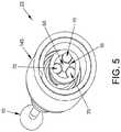
- three collet balls 70are provided, one for each of three equally-circumferentially-spaced openings 60, and shaft 50 of working element 10 has a triangular cross-section ( Fig. 5 ), whereby to provide a secure, stable connection between coupling assembly 45 and the shaft 50 of a working element 10 when the three collet balls 70 are forced radially inwardly into contact with the shaft 50 of a working element.
- the at least one collet ball 70can be replaced by at least one element having a different configuration, e.g., the at least one collet ball 70 may be replaced by at least one pin, by at least one finger, etc.
- a biasing collar 110( Fig. 4 ) is provided to selectively bias cam element 85 distally, against the power of its associated spring 105. More particularly, biasing collar 110 is itself biased distally by a spring 115 (or other biasing element), such that when biasing collar 110 is unconstrained (see below), biasing collar 110 will engage the proximal end of cam element 85 so as to force cam element 85 distally, such that first surface 90 of cam element 85 is aligned with the at least one collet ball 70 ( Fig. 4 ).
- biasing collar 110when biasing collar 110 is forced proximally (see below), against the power of spring 115, cam element 85 is free to move proximally under the power of its associated spring 105, so that transition surface 100 of cam element 85, and then second surface 95 of cam element 85, engage the at least one collet ball 70, whereby to cam the at least one collet ball 70 radially inwardly, into central lumen 75 of collet sleeve 55.
- biasing collar 110rides against the inner surface of mount 20 of handle assembly 15.
- spring 115extends between the outer race 67B of proximal bearing 65B and the proximal end of biasing collar 110.
- biasing collar 110 and spring 115do not rotate with collet sleeve 55 when collet sleeve 55 is rotated by high speed motor 30 of handle assembly 15, as will hereinafter be discussed.
- Meansare provided for (i) selectively holding biasing collar 110 proximally spaced from cam element 85 (even when cam element 85 is biased proximally under the power of spring 105) so that frictional forces are not created between cam element 85 (which rotates with shaft 40 of high speed motor 30) and biasing collar 110 (which does not rotate with shaft 40 of high speed motor 30), and (ii) allowing the user to force biasing collar 110 proximally, against the power of spring 115, so that cam element 85 can move proximally under the power of its associated spring 105 and thereby drive the at least one collet ball 70 into central lumen 75 of collet sleeve 55, whereby to lock the shaft 50 of a working element 10 within coupling assembly 45.
- At least one canted cam slot 120is provided in distal mount 20.
- the at least one canted cam slotis canted with respect to the longitudinal axis of distal mount 20.
- the at least one canted cam slot 120extends proximally and circumferentially between a distalmost surface 125 and a proximalmost surface 130.
- the at least one canted cam slot 120has a substantially straight configuration.
- the at least one canted cam slot 120has a substantially helical configuration.
- the at least one canted cam slot 120also comprises a canted cam extension 135 which extends distally, and circumferentially, from proximalmost surface 130.
- At least one pin (or other element) 140( Fig. 7 ), fixed to biasing collar 110, extends radially through the at least one canted cam slot 120 of distal mount 20, such that by moving the at least one pin 140 from its distalmost position within the at least one canted cam slot 120 ( Figs. 6 and 8 ), biasing collar 110 can be moved from its distalmost position ( Fig. 4 ) to its proximalmost position ( Fig. 9 ).
- biasing collar 110can be moved proximally within distal mount 20 so that cam element 85 is free to move proximally under the power of spring 105, whereby to cam the at least one collet ball 70 radially inwardly, whereby to intrude into central lumen 75 of collet sleeve 55 (e.g., to grip the shaft 50 of a working element 10 inserted into central lumen 75 of collet sleeve 55, or to prevent the shaft 50 of a working element 10 from being inserted into central lumen 75 of collet sleeve 55).
- the at least one pin 140is press fit or otherwise adhered to biasing collar 110.
- biasing collar 110is releasably held proximally spaced from cam element 85 so that cam element 85 can cam the at least one collet ball 70 radially inwardly so as to grip the shaft 50 of a working element 10 (and also so that no frictional forces will be created between rotating cam element 85 and stationary biasing collar 110).
- two canted cam slots 120which may be diametrically-opposed to one another, are provided in mount 20, each having an associated canted cam extension 135, and two diametrically-opposed pins 140 extend radially outward from biasing collar 110 and through the two diametrically-opposed canted cam slots 120 (see Fig. 7 ) .
- Meansare also provided for moving the at least one pin 140 within the at least one canted cam slot 120. More particularly, these means are provided by the aforementioned nosepiece assembly 22.
- nosepiece assembly 22comprises means for supporting the shaft 50 of a working element 10 (e.g., distal tip 23, which may include bearings 142, see Figs. 2 and 3 ) and a locking collar 145 (see Figs. 7 and 11 ) disposed proximal to the aforementioned distal tip 23.
- Locking collar 145is rotatable relative to distal mount 20 of handle assembly 15 when nosepiece assembly 22 is mounted to a handle assembly 15.
- locking collar 145 and distal tip 23rotate as a unit.
- locking collar 145is rotatable relative to distal tip 23.
- locking collar 145is rotatable relative to distal mount 20 of handle assembly 15 when nosepiece assembly 22 is mounted to handle assembly 15.
- distal tip 23is secured against rotation relative to distal mount 20, e.g., by the provision of a keying feature such as male-female connection, where the male feature is provided on one of the distal tip 23 and the distal mount 20, and the female feature is provided on the other of the distal tip 23 and the distal mount 20.
- Locking collar 145generally comprises at least one groove (or slot) 150 for receiving the radially-outermost portion of the at least one pin 140 when nosepiece assembly 22 is mounted on distal mount 20 of handle assembly 15.
- the at least one pin 140is also rotated, causing the at least one pin 140 to move proximally within the at least one canted cam slot 120 of distal mount 120, and hence causing biasing collar 110 to move proximally within distal mount 20 (and hence allowing cam element 85 to move proximally under the power of spring 105, whereby to cam the at least one collet ball 70 radially inwardly into the lumen 75 of collet sleeve 55).
- nosepiece assembly 22comprises two grooves (or slots) 150 for receiving the two diametrically-opposed pins 140.
- first pins 140, two canted cam slots 120, and two grooves (or slots) 150are provided, each of the two pins 140, two canted cam slots 120, and two grooves (or slots) 150 may be diametrically-opposed from one another.
- distal mount 20comprises an L-shaped groove (or slot) 155 ( Fig. 12 ) having a longitudinally-extending section 160 and a circumferentially-extending section 165.
- Locking collar 145 of nosepiece assembly 22comprises a ball 170 ( Fig.
- ball 170is received in longitudinally-extending section 160 when nosepiece assembly 22 is advanced onto distal mount 20 (or retracted off distal mount 20), and ball 170 is received in circumferentially-extending section 165 when locking collar 145 is rotated so as to (i) lock the shaft 50 of a working element 10 to coupling assembly 45 (and hence to handle assembly 15), or (ii) unlock the shaft 50 of a working element 10 from coupling assembly 45 (and hence from handle assembly 15).
- ball 170can be replaced by a corresponding pin or finger or other element which is connected to locking collar 145 and is received in L-shaped groove (or slot) 155.
- nosepiece assembly 22can be mounted to distal mount 20 of handle assembly 15 by aligning ball 170 of nosepiece assembly 22 with longitudinally-extending section 160 of L-shaped groove (or slot) 155 of distal mount 20, and then moving the two parts together until ball 170 is aligned with circumferentially-extending section 165 of L-shaped groove (or slot) 155 of distal mount 20.
- the at least one pin 140 of coupling assembly 45is received in the at least one groove (or slot) 150 of locking collar 145, and as nosepiece assembly 22 is mounted to distal mount 20 of handle assembly 15, the at least one pin 140 of coupling assembly 45 is disposed at the distal end 125 of the at least one canted cam slot 120 of distal mount 20.
- coupling assembly 45is in the position shown in Fig. 4 (i.e., unlocked).
- the shaft 50 of a working element 10may be advanced into, or retracted from, central lumen 75 of collet sleeve 55, since biasing collar 110 will normally force cam element 85 distally, so that the at least one collet ball 70 is free to move radially outward in the at least one opening 60 in collet sleeve 55.
- the shaft 50 of a working element 10can be advanced such that the at least one collet ball 70 is able to settle into at least one recess 175 ( Fig. 13 ) formed in the shaft 50 of a working element 10.
- Locking collar 145may then be rotated, whereby to cause the at least one pin 140 to move within the at least one canted cam slot 120, whereby to force biasing collar 110 proximally.
- cam element 85is free to move proximally, whereby to force the at least one collet ball 70 radially inwardly, whereby to lock shaft 50 of working element (e.g., a drill bit or burr) 10 to coupling 45.
- the at least one pin 140settles into canted cam extension 135 of the at least one canted cam slot 120. With the at least one pin 140 settled into canted cam extension 135 of the at least one canted cam slot 120, biasing collar 110 is held proximally spaced from cam element 85, so that there is no frictional contact between biasing collar 110 (which is rotationally stationary) and cam element 85 (which rotates with collet sleeve 55).
- motor 30may be energized so as to rotate its shaft 40, whereby to rotate collet sleeve 55 of coupling assembly 45, and hence rotate working element 10 (which is releasably secured to collet sleeve 55).
- Working element 10may then be used for its intended purpose, e.g., to drill or abrade bone.
- cam element 85allows the at least one collet ball 70 to move radially outwardly, whereby to free shaft 50 of working element 10 from handle assembly 15.
- the power of spring 115alone is insufficient to drive biasing collar 110 distally (and hence insufficient to drive the at least one pin 140 distally, and hence insufficient to rotate locking collar 145 about distal mount 20).
- manual movement of locking collar 145is required to drive biasing collar 110 distally (and hence to drive the at least one pin 140 distally, and hence to rotate locking collar 145 about distal mount 20) .
- the power of spring 115alone is sufficient to drive biasing collar 110 distally (and hence sufficient to drive the at least one pin 140 distally, and hence sufficient to rotate locking collar 145 about distal mount 20).
- manual motion of locking collar 145is only necessary to move the at least one pin 140 out of canted cam extension 135 and into the at least one canted cam slot 120, and manual motion of locking collar 145 is not thereafter required to drive biasing collar 110 distally (and hence to drive the at least one pin 140 distally, and hence to rotate locking collar 145 about distal mount 20).
- the equally-circumferentially-spaced recesses 175may be provided in sets (e.g., sets of three equally-circumferentially-spaced recesses), and multiple sets of the equally-circumferentially-spaced recesses 175 may be provided in axially-spaced locations along shaft 50 of working element 10, such that shafts of differing lengths may be accommodated.
- setse.g., sets of three equally-circumferentially-spaced recesses
- multiple sets of the equally-circumferentially-spaced recesses 175may be provided in axially-spaced locations along shaft 50 of working element 10, such that shafts of differing lengths may be accommodated.
- Figs. 3 and 13which show four axially-spaced sets of three equally-circumferentially-spaced recesses 175 (i.e., 175A, 175B, 175C, 175D) formed in shaft 50 of working element 10.
- the at least one pin 140may be replaced by at least one other element, e.g., at least one ball.
- the ballmay be retained in a pocket formed in biasing collar 110, and in another pocket formed in locking collar 145, with the ball extending through the at least one canted cam slot 120.
- a pinoffers significant advantages over the use of a ball, since (i) a pin can be press fit to biasing collar 110, which provides a fast and simple connection between biasing collar 110 and the pin; (ii) the height of a pin is independent of the width of the pin, whereas the "height" of a ball is the same as the "width" of the ball - so that as the "height" of the ball is increased to make a secure engagement with locking collar 145, the "width" of the ball must increase as well; and (iii) a pin generally makes a better camming contact with the at least one canted cam slot 120 than a ball. For at least these reasons, it is generally preferred to use a pin (rather than a ball) to connect biasing collar 110 to locking collar 145.
- distal tip 23 of nosepiece assembly 22may include a curved extension 180 for rotatably receiving a working element 10 having a flexible shaft.
- nosepiece assembly 22comprises a curved extension 180 and working element 10 comprises a flexible shaft, it is common to drive the working element 10 at a slower speed than where the working element 10 is substantially straight and rigid, in order to reduce the stress on the flexible shaft of the working element 10 and thereby help preserve its working life.
- handle assembly 15with means for detecting when distal tip 23 of nosepiece assembly 22 comprises a curved extension 180.
- Fig. 1In one preferred form of the invention, and looking now at Fig.
- handle assembly 15can include a plurality of Hall sensors 185, and nosepiece assembly 22 (comprising a distal tip 23 having a curved extension 180) can include a plurality of magnets 190, such that handle assembly 15 can detect when a nosepiece assembly 22 (of the sort comprising a distal tip 23 having a curved extension 180) is mounted to handle assembly 15 (and hence reduce the operating speed of motor 30 so as to preserve the working life of the working element 10).
- bearings 142may be omitted from nosepiece assembly 22, and shaft 50 of a working element 10 may be supported by a simple sliding contact made directly against nosepiece assembly 22.
- nosepiece assembly 22is configured as a separate element from handle assembly 15, and is mountable to, and fully removable from, distal mount 20 of handle assembly 15.
- nosepiece assembly 22as a fully-separable element from handle assembly 15, it is possible to provide a wide variety of different nosepiece assemblies 22, with each nosepiece assembly 22 being configured for a different purpose (e.g., for performing a different task, for supporting a differently-configured working element, etc.), with each nosepiece assembly 22 comprising a distal tip 23 for slidably supporting a working tool 10 and a locking collar 145 for engaging the at least one pin 140 of a coupling assembly 45 disposed in distal mount 20 of handle assembly 15.
- the nosepiece assemblymay be configured to provide an angled shaft configuration.
- a nosepiece assembly 22Awhich comprises the aforementioned locking collar 145 for engaging the at least one pin 140 of coupling assembly 45 of handle assembly 15, and the aforementioned distal tip 23 for slidably receiving the shaft 50 of a working tool 10.
- nosepiece assembly 22Aalso comprises a second coupling assembly 45A, a second locking collar 145A, and a pair of shafts 195, 200.
- Second coupling assembly 45Ais substantially the same as the coupling assembly 45 previously disclosed, except that it is disposed in nosepiece assembly 122A distal to locking collar 145.
- Second locking collar 145Ais provided on nosepiece assembly 22A and is configured to engage the at least one pin 140A of second coupling assembly 45A, whereby to lock or unlock a working element 10 to second coupling assembly 45A.
- Shaft 200is received by the aforementioned coupling assembly 45 in distal mount 20 of handle assembly 15 when nosepiece assembly 22 is mounted to handle assembly 15, such that when locking collar 145 is rotated, shaft 195 is mechanically connected (via coupling assembly 45 in distal mount 20 of handle assembly 15) to drive shaft 40 of high speed motor 30.
- Shaft 195includes a beveled gear 205 at its distal end.
- Shaft 200is connected to collet sleeve 55A of coupling assembly 45A, and includes a beveled gear 210 at its proximal end which is rotatably connected to gear 205 of shaft 195, such that when shaft 40 of high speed motor 30 is rotated, collet sleeve 55A is also rotated (i.e., via the intervening collet sleeve 55 of coupling assembly 45 of handle assembly 15, and via the intervening shaft 195 and shaft 200 of nosepiece assembly 22).
- second coupling 45A of nosepiece assembly 22releasably receives the shaft 50 of working element 10.
- Second locking collar 145A of nosepiece assembly 22Ais used to selectively lock/unlock the shaft 50 of a working element 10 to second coupling assembly 45A of nosepiece 22A.
- nosepiece assembly 22Aby forming nosepiece assembly 22A so that the longitudinal axis of shaft 195 is set at an angle to the longitudinal axis of collet sleeve 55A of second coupling 45A, "off-angle" drilling can be effected without requiring the use of a nosepiece assembly having a curved extension 180 and a drill bit having a flexible shaft. This is a significant advance in the art, since it allows high speed "off angle" drilling or burring to be effected for prolonged periods of time without unduly limiting the life of working element 10.
- the angled shaft nosepiece assembly 22A( Figs. 16-19 ) can be provided as a single assembly, which mounts and dismounts as a unit from distal mount 20 of handle assembly 15.
- a nosepiece assembly 22Bwhich comprises (i) a nosepiece assembly 22C, and (ii) a handle assembly adapter 22D, wherein nosepiece assembly 22C and handle assembly adapter 22D are separable from one another ( Figs. 20-22 ), but may be connected together, e.g., at the time of manufacture, at the time of use, etc. ( Figs. 23 and 24 ), so as to together form the complete nosepiece assembly 22B.
- the nosepiece assembly 22Bmay be an angled shaft nosepiece assembly.
- nosepiece assembly 22Cmay be identical to the aforementioned nosepiece assembly 22, i.e., nosepiece assembly 22C comprises a distal tip 23C and a locking collar 145C.
- handle assembly adapter 22Dmay comprise a distal mount 20D containing a coupling assembly 45D which receives the shaft 50 of a working element 10 and is activated by locking collar 145C of nosepiece assembly 22C.
- handle assembly adapter 22Dmay comprise a shaft 195D for being received in coupling assembly 45 in distal mount 20 of handle assembly 15, and a shaft 200D for transferring the rotation of shaft 195D to collet sleeve 55D of coupling assembly 45D disposed in handle assembly adapter 22D (and hence transferring rotation of shaft 195D to the shaft 50 of a working element 10 disposed in central lumen 75D of collet sleeve 55D).
- handle assembly adapter 22Dcomprises a locking collar 145D for actuating coupling assembly 45 in distal mount 20 of handle assembly 15. It will also be appreciated that in this form of the invention, handle assembly adapter 22D is releasably secured to distal mount 20 of handle assembly 15 by loading locking collar 145D of handle assembly adapter 22D onto distal mount 20 of handle assembly 15 in a manner analogous to the manner in which nosepiece assembly 22 is mounted onto distal mount 20 of handle assembly 15, and in this form of the invention, nosepiece assembly 22C is releasably secured to distal mount 20D of handle assembly adapter 22D by loading locking collar 145C of nosepiece assembly 22C onto distal mount 20D of handle assembly adapter 22D in a manner analogous to the manner in which nosepiece assembly 22 is mounted onto distal mount 20 of handle assembly 15.
- nosepiece assembly 22Bcomprises a first mounting mechanism comprising a locking collar 145D for securing handle assembly adapter 22D to distal mount 20 of handle assembly 15, and a second mounting mechanism for securing nosepiece assembly 22C to distal mount 20D of handle assembly adapter 22D.
- an alternative mounting mechanismmay be used to secure handle assembly adapter 22D to distal mount 20 of handle assembly 15 (while still using a locking collar 145C to secure nosepiece assembly 22C to handle assembly adapter 22D); and/or an alternaive mounting mechanism may be used to secure nosepiece assembly 22C to handle assembly adapter 22D (while still using the aforementioned locking collar 145D to secure handle assembly adapter 22D to distal mount 20 of handle assembly 15).
Landscapes
- Health & Medical Sciences (AREA)
- Surgery (AREA)
- Life Sciences & Earth Sciences (AREA)
- Engineering & Computer Science (AREA)
- Biomedical Technology (AREA)
- Molecular Biology (AREA)
- Orthopedic Medicine & Surgery (AREA)
- Oral & Maxillofacial Surgery (AREA)
- Dentistry (AREA)
- Heart & Thoracic Surgery (AREA)
- Medical Informatics (AREA)
- Nuclear Medicine, Radiotherapy & Molecular Imaging (AREA)
- Animal Behavior & Ethology (AREA)
- General Health & Medical Sciences (AREA)
- Public Health (AREA)
- Veterinary Medicine (AREA)
- Mechanical Engineering (AREA)
- Surgical Instruments (AREA)
- Dental Tools And Instruments Or Auxiliary Dental Instruments (AREA)
Description
US 5,505,737A describes a coupling device for attaching a dissecting tool to a rotary shaft of a surgical instrument. This device has the below mentioned disadvantages.- This invention relates to surgical apparatus and procedures in general, and more particularly to rotary tools of the sort used to drive working elements such as drill bits and burrs.
- In many surgical procedures, it is necessary or desirable to drill or abrade an object, e.g., bone. In these situations, it is common to provide a rotary tool comprising a handle assembly having a high speed motor, and a coupling assembly at the distal end of the handle assembly for releasably connecting a working element (e.g., a drill bit or burr) to the high speed motor, such that the working element (e.g., the drill bit or burr) can be turned by the high speed motor and then used for the desired purpose (e.g., drilling or abrading bone).
- The present invention provides a novel coupling assembly for releasably connecting a working element (e.g., a drill bit or burr) to a high speed motor of a handle assembly of a rotary tool.
- For purposes of clarity of description, the present invention will sometimes hereinafter be discussed in the context of a high speed drill bit or burr, however, it should be appreciated that the present invention is also applicable to other working elements, e.g., a dental polishing head, etc.
- The present invention comprises the provision and use of a novel coupling assembly for releasably connecting a working element (e.g., a drill bit or burr) to a high speed motor of a handle assembly of a rotary tool.
- For purposes of clarity of description, the present invention will sometimes hereinafter be discussed in the context of a high speed drill bit or burr, however, it should be appreciated that the present invention is also applicable to other working elements, e.g., a dental polishing head, etc.
- In one preferred form of the invention, there is provided a surgical device according to independent claim 1.
- In another preferred form of the invention, there is provided a surgical device according to independent claim 4.
- In another preferred form of the invention, there is provided a surgical device according to
independent claim 5. - Preferred embodiments are defined by the dependent claims.
- In another preferred form of the invention, there is provided a method for securing a replaceable bit to a handpiece surgical device according to independent claim 14.
- These and other objects and features of the present invention will be more fully disclosed or rendered obvious by the following detailed description of the preferred embodiments of the invention, which is to be considered together with the accompanying drawings wherein only the rotary tools shown in
Figs. 16-24 are embodiments of the present invention, whereas the rotary tools shown inFigs. 1-15 do not fall within the scope of the appended claims, wherein like numbers refer to like parts and further wherein: Fig. 1 is a schematic view showing a novel rotary tool provided in accordance with the present invention;Fig. 2 is an exploded schematic view of the novel rotary tool shown inFig. 1 ;Fig. 3 is a sectional schematic view of the novel rotary tool shown inFig. 1 ;Figs. 4-13 are schematic views showing construction details of the novel rotary tool shown inFig. 1 ;Figs. 14 and15 are schematic views showing another novel rotary tool provided in accordance with the present invention;Figs. 16 and17 are schematic views showing still another novel rotary tool provided in accordance with the present invention;Figs. 18 and19 are schematic views showing construction details of the novel rotary tool shown inFigs. 16 and17 ;Figs. 20-24 are schematic views showing yet another novel rotary tool provided in accordance with the present invention.- The present invention comprises the provision and use of a novel coupling assembly for releasably connecting a working element (e.g., a drill bit or burr) to a high speed motor of a handle assembly of a rotary tool.
- For purposes of clarity of description, the present invention will sometimes hereinafter be discussed in the context of a high speed drill bit or burr, however, it should be appreciated that the present invention is also applicable to other working elements, e.g., a dental polishing head, etc.
- Looking first at
Figs. 1-3 , there is shown a novelrotary tool 5 for turning a working element (e.g., a drill bit or burr) 10.Rotary tool 5 generally comprises ahandle assembly 15 having adistal mount 20 extending distally therefrom, and anosepiece assembly 22 mountable to, and fully removable from,distal mount 20 ofhandle assembly 15.Nosepiece assembly 22 comprises adistal tip 23 for rotatably supportingworking element 10. - More particularly,
handle assembly 15 comprises acavity 25 having a high speed motor 30 (e.g., an 80,000 rpm motor) disposed therein.Distal mount 20 ofhandle assembly 15 comprises acavity 35.Cavity 35 indistal mount 20 may be aligned withcavity 25 inhandle assembly 15.High speed motor 30 turns ashaft 40 which extends intocavity 35 indistal mount 20. - A
coupling assembly 45, generally disposed indistal mount 20 ofhandle assembly 15, releasably receives theshaft 50 of workingelement 10 and selectively couples the shaft of the working element tohigh speed motor 30. - More particularly, and looking now at
Fig. 4 ,coupling assembly 45 generally comprises acollet sleeve 55 which is secured toshaft 40 ofhigh speed motor 30.Collet sleeve 55 is preferably connected toshaft 40 ofhigh speed motor 30 by a universal joint or a similar type of connector so as to minimize alignment and vibration issues.Collet sleeve 55 is sized to receiveshaft 50 of working element 10 (Fig. 3 ), and comprises at least one opening 60 extending through the side wall ofcollet sleeve 55. In one preferred form of the invention,collet sleeve 55 comprises threeopenings 60 extending through the side wall ofcollet sleeve 55. The threeopenings 60 may be equally-circumferentially spaced about the longitudinal axis ofcollet sleeve 55.Collet sleeve 55 is rotatably mounted withincavity 35 ofdistal mount 20, e.g., by a plurality ofbearings 65. In this way, whenshaft 40 ofhigh speed motor 30 is turned,collet sleeve 55 is also turned. In one preferred form of the invention, there is provided a distal bearing 65A comprising an inner race 66A secured tocollet sleeve 55 and anouter race 67A secured to distalmount 20; and aproximal bearing 65B comprising an inner race 66B secured tocollet sleeve 55 and anouter race 67B secured to distalmount 20. - In order for
coupling assembly 45 to releasablysecure shaft 50 of workingelement 10 tocollet sleeve 55,coupling assembly 45 also comprises at least one collet ball 70 (or other locking element) which is disposed in the at least one opening 60 of collet sleeve 55 (where threeopenings 60 are provided incollet sleeve 55, threecollet balls 70 may be provided, with onecollet ball 70 being disposed in each opening 60). Note that the at least one opening 60 ofcollet sleeve 55 is configured so that the at least onecollet ball 70 can protrude into thecentral lumen 75 ofcollet sleeve 55, but the at least onecollet ball 70 cannot pass completely intocentral lumen 75 ofcollet sleeve 55 due to the provision ofshoulders 80 at the innermost points of the at least one opening 60. In an alternative construction, the at least one opening 60 comprises at least one tapered opening, in whichcase shoulders 80 are replaced by the tapering side wall of the at least one tapered opening. - A
cam element 85 is disposed aboutcollet sleeve 55.Cam element 85 comprises afirst surface 90 and asecond surface 95, with atransition surface 100 disposed therebetween. As will hereinafter be discussed, whenfirst surface 90 ofcam element 85 is aligned with the at least onecollet ball 70, the at least onecollet ball 70 is free to move radially outward to the extent necessary so that the at least onecollet ball 70 does not intrude intocentral lumen 75 ofcollet sleeve 55; at the same time, whenfirst surface 90 ofcam element 85 is aligned with the at least onecollet ball 70,first surface 90 will prevent the at least onecollet ball 70 from completely exiting the at least one opening 60, so that the at least onecollet ball 70 will remain connected tocollet sleeve 55. As a result, whenfirst surface 90 ofcam element 85 is aligned with the at least onecollet ball 70,first surface 90 will limit radially-outward movement of the at least onecollet ball 70 and prevent the at least onecollet ball 70 from "completely falling out of" the at least one opening 60 and becoming loose withincavity 35. However, whencam element 85 is moved proximally (e.g., under the power of aspring 105 or other biasing element),transition surface 100 ofcam element 85, and thensecond surface 95 ofcam element 85, will engage the at least onecollet ball 70, whereby to cam the at least onecollet ball 70 radially inwardly, intocentral lumen 75 of collet sleeve 55 (whereby to secure theshaft 50 of a workingelement 10 to collet sleeve 55). - It should be appreciated that
cam element 85 andspring 105 rotate in conjunction withcollet sleeve 55, withspring 105 extending between the inner race 66A of distal bearing 65A and the distal end ofcam element 85. - Note that in one preferred construction, three
collet balls 70 are provided, one for each of three equally-circumferentially-spacedopenings 60, andshaft 50 of workingelement 10 has a triangular cross-section (Fig. 5 ), whereby to provide a secure, stable connection betweencoupling assembly 45 and theshaft 50 of a workingelement 10 when the threecollet balls 70 are forced radially inwardly into contact with theshaft 50 of a working element. Note also that, if desired, the at least onecollet ball 70 can be replaced by at least one element having a different configuration, e.g., the at least onecollet ball 70 may be replaced by at least one pin, by at least one finger, etc. - A biasing collar 110 (
Fig. 4 ) is provided to selectivelybias cam element 85 distally, against the power of its associatedspring 105. More particularly, biasingcollar 110 is itself biased distally by a spring 115 (or other biasing element), such that when biasingcollar 110 is unconstrained (see below), biasingcollar 110 will engage the proximal end ofcam element 85 so as to forcecam element 85 distally, such thatfirst surface 90 ofcam element 85 is aligned with the at least one collet ball 70 (Fig. 4 ). However, when biasingcollar 110 is forced proximally (see below), against the power ofspring 115,cam element 85 is free to move proximally under the power of its associatedspring 105, so thattransition surface 100 ofcam element 85, and thensecond surface 95 ofcam element 85, engage the at least onecollet ball 70, whereby to cam the at least onecollet ball 70 radially inwardly, intocentral lumen 75 ofcollet sleeve 55. In one preferred form of the invention, biasingcollar 110 rides against the inner surface ofmount 20 ofhandle assembly 15. - Note that
spring 115 extends between theouter race 67B of proximal bearing 65B and the proximal end of biasingcollar 110. - Note also that biasing
collar 110 andspring 115 do not rotate withcollet sleeve 55 whencollet sleeve 55 is rotated byhigh speed motor 30 ofhandle assembly 15, as will hereinafter be discussed. - Means are provided for (i) selectively holding biasing
collar 110 proximally spaced from cam element 85 (even whencam element 85 is biased proximally under the power of spring 105) so that frictional forces are not created between cam element 85 (which rotates withshaft 40 of high speed motor 30) and biasing collar 110 (which does not rotate withshaft 40 of high speed motor 30), and (ii) allowing the user to force biasingcollar 110 proximally, against the power ofspring 115, so thatcam element 85 can move proximally under the power of its associatedspring 105 and thereby drive the at least onecollet ball 70 intocentral lumen 75 ofcollet sleeve 55, whereby to lock theshaft 50 of a workingelement 10 withincoupling assembly 45. - More particularly, and looking now at
Fig. 6 , at least one cantedcam slot 120 is provided indistal mount 20. The at least one canted cam slot is canted with respect to the longitudinal axis ofdistal mount 20. The at least onecanted cam slot 120 extends proximally and circumferentially between adistalmost surface 125 and aproximalmost surface 130. In one preferred form of the invention, the at least onecanted cam slot 120 has a substantially straight configuration. In another preferred form of the invention, the at least onecanted cam slot 120 has a substantially helical configuration. The at least onecanted cam slot 120 also comprises a cantedcam extension 135 which extends distally, and circumferentially, fromproximalmost surface 130. At least one pin (or other element) 140 (Fig. 7 ), fixed to biasingcollar 110, extends radially through the at least onecanted cam slot 120 ofdistal mount 20, such that by moving the at least onepin 140 from its distalmost position within the at least one canted cam slot 120 (Figs. 6 and8 ), biasingcollar 110 can be moved from its distalmost position (Fig. 4 ) to its proximalmost position (Fig. 9 ). Thus, by moving the at least onepin 140 proximally within the at least onecanted cam slot 120, biasingcollar 110 can be moved proximally withindistal mount 20 so thatcam element 85 is free to move proximally under the power ofspring 105, whereby to cam the at least onecollet ball 70 radially inwardly, whereby to intrude intocentral lumen 75 of collet sleeve 55 (e.g., to grip theshaft 50 of a workingelement 10 inserted intocentral lumen 75 ofcollet sleeve 55, or to prevent theshaft 50 of a workingelement 10 from being inserted intocentral lumen 75 of collet sleeve 55). In one preferred form of the invention, the at least onepin 140 is press fit or otherwise adhered to biasingcollar 110. - In addition, by moving the at least one
pin 140 into cantedcam extension 135 of the at least one canted cam slot 120 (Fig. 10 ), biasingcollar 110 is releasably held proximally spaced fromcam element 85 so thatcam element 85 can cam the at least onecollet ball 70 radially inwardly so as to grip theshaft 50 of a working element 10 (and also so that no frictional forces will be created betweenrotating cam element 85 and stationary biasing collar 110). In one preferred form of the invention, twocanted cam slots 120, which may be diametrically-opposed to one another, are provided inmount 20, each having an associatedcanted cam extension 135, and two diametrically-opposedpins 140 extend radially outward from biasingcollar 110 and through the two diametrically-opposed canted cam slots 120 (seeFig. 7 ) . - Means are also provided for moving the at least one
pin 140 within the at least onecanted cam slot 120. More particularly, these means are provided by theaforementioned nosepiece assembly 22. - Looking now at
Figs. 2 ,3 ,7 and11 ,nosepiece assembly 22 comprises means for supporting theshaft 50 of a working element 10 (e.g.,distal tip 23, which may includebearings 142, seeFigs. 2 and3 ) and a locking collar 145 (seeFigs. 7 and11 ) disposed proximal to the aforementioneddistal tip 23. Lockingcollar 145 is rotatable relative todistal mount 20 ofhandle assembly 15 whennosepiece assembly 22 is mounted to ahandle assembly 15. In one preferred form of the invention, lockingcollar 145 anddistal tip 23 rotate as a unit. In another preferred form of the invention, lockingcollar 145 is rotatable relative todistal tip 23. In either case, however, lockingcollar 145 is rotatable relative todistal mount 20 ofhandle assembly 15 whennosepiece assembly 22 is mounted to handleassembly 15. Note that where lockingcollar 145 is rotatable relative todistal tip 23,distal tip 23 is secured against rotation relative todistal mount 20, e.g., by the provision of a keying feature such as male-female connection, where the male feature is provided on one of thedistal tip 23 and thedistal mount 20, and the female feature is provided on the other of thedistal tip 23 and thedistal mount 20. - Locking
collar 145 generally comprises at least one groove (or slot) 150 for receiving the radially-outermost portion of the at least onepin 140 whennosepiece assembly 22 is mounted ondistal mount 20 ofhandle assembly 15. As a result, when lockingcollar 145 is rotated, the at least onepin 140 is also rotated, causing the at least onepin 140 to move proximally within the at least onecanted cam slot 120 ofdistal mount 120, and hence causing biasingcollar 110 to move proximally within distal mount 20 (and hence allowingcam element 85 to move proximally under the power ofspring 105, whereby to cam the at least onecollet ball 70 radially inwardly into thelumen 75 of collet sleeve 55). In one preferred form of the invention, wherecoupling assembly 45 comprises twopins 140 extending through twocanted cam slots 120 ofdistal mount 120,nosepiece assembly 22 comprises two grooves (or slots) 150 for receiving the two diametrically-opposedpins 140. Where twopins 140, twocanted cam slots 120, and two grooves (or slots) 150 are provided, each of the twopins 140, twocanted cam slots 120, and two grooves (or slots) 150 may be diametrically-opposed from one another. - In order to releasably
lock nosepiece assembly 22 todistal mount 20,distal mount 20 comprises an L-shaped groove (or slot) 155 (Fig. 12 ) having a longitudinally-extendingsection 160 and a circumferentially-extendingsection 165. Lockingcollar 145 ofnosepiece assembly 22 comprises a ball 170 (Fig. 11 ) which is received in L-shaped groove (or slot) 155, i.e.,ball 170 is received in longitudinally-extendingsection 160 whennosepiece assembly 22 is advanced onto distal mount 20 (or retracted off distal mount 20), andball 170 is received in circumferentially-extendingsection 165 when lockingcollar 145 is rotated so as to (i) lock theshaft 50 of a workingelement 10 to coupling assembly 45 (and hence to handle assembly 15), or (ii) unlock theshaft 50 of a workingelement 10 from coupling assembly 45 (and hence from handle assembly 15). If desired,ball 170 can be replaced by a corresponding pin or finger or other element which is connected to lockingcollar 145 and is received in L-shaped groove (or slot) 155. - Thus it will be seen that
nosepiece assembly 22 can be mounted todistal mount 20 ofhandle assembly 15 by aligningball 170 ofnosepiece assembly 22 with longitudinally-extendingsection 160 of L-shaped groove (or slot) 155 ofdistal mount 20, and then moving the two parts together untilball 170 is aligned with circumferentially-extendingsection 165 of L-shaped groove (or slot) 155 ofdistal mount 20. As this occurs, the at least onepin 140 ofcoupling assembly 45 is received in the at least one groove (or slot) 150 of lockingcollar 145, and asnosepiece assembly 22 is mounted todistal mount 20 ofhandle assembly 15, the at least onepin 140 ofcoupling assembly 45 is disposed at thedistal end 125 of the at least onecanted cam slot 120 ofdistal mount 20. At this point, couplingassembly 45 is in the position shown inFig. 4 (i.e., unlocked). - Thereafter, the
shaft 50 of a workingelement 10 may be advanced into, or retracted from,central lumen 75 ofcollet sleeve 55, since biasingcollar 110 will normally forcecam element 85 distally, so that the at least onecollet ball 70 is free to move radially outward in the at least oneopening 60 incollet sleeve 55. Theshaft 50 of a workingelement 10 can be advanced such that the at least onecollet ball 70 is able to settle into at least one recess 175 (Fig. 13 ) formed in theshaft 50 of a workingelement 10. Note that in one preferred form of the invention, where three equally-circumferentially-spacedopenings 60 and threecollet balls 70 are provided, three equally-circumferentially-spacedrecesses 175 are also provided, such that each equally-circumferentially-spacedrecess 175 can receive onecollet ball 70. - Locking
collar 145 may then be rotated, whereby to cause the at least onepin 140 to move within the at least onecanted cam slot 120, whereby to force biasingcollar 110 proximally. As this occurs,cam element 85 is free to move proximally, whereby to force the at least onecollet ball 70 radially inwardly, whereby to lockshaft 50 of working element (e.g., a drill bit or burr) 10 tocoupling 45. - At the end of the rotation of locking
collar 145, the at least onepin 140 settles into cantedcam extension 135 of the at least onecanted cam slot 120. With the at least onepin 140 settled into cantedcam extension 135 of the at least onecanted cam slot 120, biasingcollar 110 is held proximally spaced fromcam element 85, so that there is no frictional contact between biasing collar 110 (which is rotationally stationary) and cam element 85 (which rotates with collet sleeve 55). - At this point,
motor 30 may be energized so as to rotate itsshaft 40, whereby to rotatecollet sleeve 55 ofcoupling assembly 45, and hence rotate working element 10 (which is releasably secured to collet sleeve 55). Workingelement 10 may then be used for its intended purpose, e.g., to drill or abrade bone. - Thereafter, when working
element 10 is to be released fromhandle assembly 15, lockingcollar 145 ofnosepiece assembly 22 is rotated again, but this time in the opposite direction, whereby to cause the at least onepin 140 to move out of cantedcam extension 135 of the at least onecanted cam slot 120, and then distally along the at least onecanted cam slot 120, whereby to cause biasingcollar 110 to move distally, such thatcam element 85 also moves distally. As this occurs,cam element 85 allows the at least onecollet ball 70 to move radially outwardly, whereby tofree shaft 50 of workingelement 10 fromhandle assembly 15. - Note that in one preferred form of the invention, when the at least one
pin 140 is in the at least onecanted cam slot 120, the power ofspring 115 alone is insufficient to drive biasingcollar 110 distally (and hence insufficient to drive the at least onepin 140 distally, and hence insufficient to rotate lockingcollar 145 about distal mount 20). In this form of the invention, manual movement of lockingcollar 145 is required to drive biasingcollar 110 distally (and hence to drive the at least onepin 140 distally, and hence to rotate lockingcollar 145 about distal mount 20) . - However, in another form of the invention, when the at least one
pin 140 is in the at least onecanted cam slot 120, the power ofspring 115 alone is sufficient to drive biasingcollar 110 distally (and hence sufficient to drive the at least onepin 140 distally, and hence sufficient to rotate lockingcollar 145 about distal mount 20). In this form of the invention, manual motion of lockingcollar 145 is only necessary to move the at least onepin 140 out of cantedcam extension 135 and into the at least onecanted cam slot 120, and manual motion of lockingcollar 145 is not thereafter required to drive biasingcollar 110 distally (and hence to drive the at least onepin 140 distally, and hence to rotate lockingcollar 145 about distal mount 20). - In one preferred form of the invention, the equally-circumferentially-spaced
recesses 175 may be provided in sets (e.g., sets of three equally-circumferentially-spaced recesses), and multiple sets of the equally-circumferentially-spacedrecesses 175 may be provided in axially-spaced locations alongshaft 50 of workingelement 10, such that shafts of differing lengths may be accommodated. By way of example but not limitation, seeFigs. 3 and13 , which show four axially-spaced sets of three equally-circumferentially-spaced recesses 175 (i.e., 175A, 175B, 175C, 175D) formed inshaft 50 of workingelement 10. - If desired, the at least one
pin 140 may be replaced by at least one other element, e.g., at least one ball. Where a ball is used in place of a pin, the ball may be retained in a pocket formed in biasingcollar 110, and in another pocket formed in lockingcollar 145, with the ball extending through the at least onecanted cam slot 120. However, the use of a pin offers significant advantages over the use of a ball, since (i) a pin can be press fit to biasingcollar 110, which provides a fast and simple connection between biasingcollar 110 and the pin; (ii) the height of a pin is independent of the width of the pin, whereas the "height" of a ball is the same as the "width" of the ball - so that as the "height" of the ball is increased to make a secure engagement with lockingcollar 145, the "width" of the ball must increase as well; and (iii) a pin generally makes a better camming contact with the at least onecanted cam slot 120 than a ball. For at least these reasons, it is generally preferred to use a pin (rather than a ball) to connect biasingcollar 110 to lockingcollar 145. - As seen in
Figs. 14 and15 ,distal tip 23 ofnosepiece assembly 22 may include acurved extension 180 for rotatably receiving a workingelement 10 having a flexible shaft. Note that wherenosepiece assembly 22 comprises acurved extension 180 and workingelement 10 comprises a flexible shaft, it is common to drive the workingelement 10 at a slower speed than where the workingelement 10 is substantially straight and rigid, in order to reduce the stress on the flexible shaft of the workingelement 10 and thereby help preserve its working life. To this end, it can be advantageous to providehandle assembly 15 with means for detecting whendistal tip 23 ofnosepiece assembly 22 comprises acurved extension 180. In one preferred form of the invention, and looking now atFig. 15 , handleassembly 15 can include a plurality ofHall sensors 185, and nosepiece assembly 22 (comprising adistal tip 23 having a curved extension 180) can include a plurality ofmagnets 190, such thathandle assembly 15 can detect when a nosepiece assembly 22 (of the sort comprising adistal tip 23 having a curved extension 180) is mounted to handle assembly 15 (and hence reduce the operating speed ofmotor 30 so as to preserve the working life of the working element 10). - Note that, if desired, and as shown in
Figs. 14 and15 ,bearings 142 may be omitted fromnosepiece assembly 22, andshaft 50 of a workingelement 10 may be supported by a simple sliding contact made directly againstnosepiece assembly 22. - As noted above, in accordance with the present invention,
nosepiece assembly 22 is configured as a separate element fromhandle assembly 15, and is mountable to, and fully removable from,distal mount 20 ofhandle assembly 15. - It should be appreciated that, by providing
nosepiece assembly 22 as a fully-separable element fromhandle assembly 15, it is possible to provide a wide variety ofdifferent nosepiece assemblies 22, with eachnosepiece assembly 22 being configured for a different purpose (e.g., for performing a different task, for supporting a differently-configured working element, etc.), with eachnosepiece assembly 22 comprising adistal tip 23 for slidably supporting a workingtool 10 and alocking collar 145 for engaging the at least onepin 140 of acoupling assembly 45 disposed indistal mount 20 ofhandle assembly 15. - Significantly, the nosepiece assembly may be configured to provide an angled shaft configuration. In this form of the invention, and looking now at
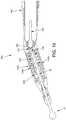
Figs. 16-19 , there is provided anosepiece assembly 22A which comprises theaforementioned locking collar 145 for engaging the at least onepin 140 ofcoupling assembly 45 ofhandle assembly 15, and the aforementioneddistal tip 23 for slidably receiving theshaft 50 of a workingtool 10. However, in this form of the invention,nosepiece assembly 22A also comprises asecond coupling assembly 45A, asecond locking collar 145A, and a pair ofshafts Second coupling assembly 45A is substantially the same as thecoupling assembly 45 previously disclosed, except that it is disposed in nosepiece assembly 122A distal to lockingcollar 145.Second locking collar 145A is provided onnosepiece assembly 22A and is configured to engage the at least onepin 140A ofsecond coupling assembly 45A, whereby to lock or unlock a workingelement 10 tosecond coupling assembly 45A.Shaft 200 is received by theaforementioned coupling assembly 45 indistal mount 20 ofhandle assembly 15 whennosepiece assembly 22 is mounted to handleassembly 15, such that when lockingcollar 145 is rotated,shaft 195 is mechanically connected (viacoupling assembly 45 indistal mount 20 of handle assembly 15) to driveshaft 40 ofhigh speed motor 30.Shaft 195 includes abeveled gear 205 at its distal end.Shaft 200 is connected to colletsleeve 55A ofcoupling assembly 45A, and includes abeveled gear 210 at its proximal end which is rotatably connected to gear 205 ofshaft 195, such that whenshaft 40 ofhigh speed motor 30 is rotated,collet sleeve 55A is also rotated (i.e., via the interveningcollet sleeve 55 ofcoupling assembly 45 ofhandle assembly 15, and via the interveningshaft 195 andshaft 200 of nosepiece assembly 22). In this form of the invention,second coupling 45A ofnosepiece assembly 22 releasably receives theshaft 50 of workingelement 10.Second locking collar 145A ofnosepiece assembly 22A is used to selectively lock/unlock theshaft 50 of a workingelement 10 tosecond coupling assembly 45A ofnosepiece 22A. - Significantly, by forming
nosepiece assembly 22A so that the longitudinal axis ofshaft 195 is set at an angle to the longitudinal axis ofcollet sleeve 55A ofsecond coupling 45A, "off-angle" drilling can be effected without requiring the use of a nosepiece assembly having acurved extension 180 and a drill bit having a flexible shaft. This is a significant advance in the art, since it allows high speed "off angle" drilling or burring to be effected for prolonged periods of time without unduly limiting the life of workingelement 10. - If desired, the angled
shaft nosepiece assembly 22A (Figs. 16-19 ) can be provided as a single assembly, which mounts and dismounts as a unit fromdistal mount 20 ofhandle assembly 15. - Alternatively, if desired, and looking now at
Figs. 20-24 , there is shown anosepiece assembly 22B which comprises (i) anosepiece assembly 22C, and (ii) a handle assembly adapter 22D, whereinnosepiece assembly 22C and handle assembly adapter 22D are separable from one another (Figs. 20-22 ), but may be connected together, e.g., at the time of manufacture, at the time of use, etc. (Figs. 23 and24 ), so as to together form thecomplete nosepiece assembly 22B. Thenosepiece assembly 22B may be an angled shaft nosepiece assembly. - In this form of the invention,
nosepiece assembly 22C may be identical to theaforementioned nosepiece assembly 22, i.e.,nosepiece assembly 22C comprises adistal tip 23C and alocking collar 145C. - In this form of the invention, handle assembly adapter 22D may comprise a
distal mount 20D containing acoupling assembly 45D which receives theshaft 50 of a workingelement 10 and is activated by lockingcollar 145C ofnosepiece assembly 22C. And in this form of the invention, handle assembly adapter 22D may comprise a shaft 195D for being received incoupling assembly 45 indistal mount 20 ofhandle assembly 15, and ashaft 200D for transferring the rotation of shaft 195D tocollet sleeve 55D ofcoupling assembly 45D disposed in handle assembly adapter 22D (and hence transferring rotation of shaft 195D to theshaft 50 of a workingelement 10 disposed incentral lumen 75D ofcollet sleeve 55D). In this form of the invention, handle assembly adapter 22D comprises alocking collar 145D for actuatingcoupling assembly 45 indistal mount 20 ofhandle assembly 15. It will also be appreciated that in this form of the invention, handle assembly adapter 22D is releasably secured todistal mount 20 ofhandle assembly 15 by loadinglocking collar 145D of handle assembly adapter 22D ontodistal mount 20 ofhandle assembly 15 in a manner analogous to the manner in whichnosepiece assembly 22 is mounted ontodistal mount 20 ofhandle assembly 15, and in this form of the invention,nosepiece assembly 22C is releasably secured todistal mount 20D of handle assembly adapter 22D by loadinglocking collar 145C ofnosepiece assembly 22C ontodistal mount 20D of handle assembly adapter 22D in a manner analogous to the manner in whichnosepiece assembly 22 is mounted ontodistal mount 20 ofhandle assembly 15. - Thus it will be seen that, in this form of the invention,
nosepiece assembly 22B comprises a first mounting mechanism comprising alocking collar 145D for securing handle assembly adapter 22D todistal mount 20 ofhandle assembly 15, and a second mounting mechanism for securingnosepiece assembly 22C todistal mount 20D of handle assembly adapter 22D. However, it should also be appreciated that, if desired, an alternative mounting mechanism may be used to secure handle assembly adapter 22D todistal mount 20 of handle assembly 15 (while still using alocking collar 145C to securenosepiece assembly 22C to handle assembly adapter 22D); and/or an alternaive mounting mechanism may be used to securenosepiece assembly 22C to handle assembly adapter 22D (while still using theaforementioned locking collar 145D to secure handle assembly adapter 22D todistal mount 20 of handle assembly 15). - It should be understood that many additional changes in the details, materials, steps and arrangements of parts, which have been herein described and illustrated in order to explain the nature of the present invention, may be made by those skilled in the art while still remaining within the principles and scope of the invention, which is only limited by the appended claims.
Claims (15)
- A surgical device (5) comprising:a handle assembly (15) comprising a rotatable drive shaft;a removable handle assembly adapter (22D) for connection to said handle assembly, said removable handle assembly adapter comprising a rotatable transmission shaft (195, 200) for connection to said rotatable drive shaft of said handle assembly; anda removable nosepiece assembly (22C) for connection to said removable handle assembly adapter and for selectively securing the shaft (50) of a working element (10) to said rotatable transmission shaft of said removable handle assembly adapter;wherein said removable handle assembly adapter and said removable nosepiece assembly each comprise a locking collar (145C, 145D) ; andwherein said removable handle assembly adapter and said handle assembly each comprise a connector assembly, said connector assembly comprising:a housing comprising an opening and a canted slot (120) ;a collet sleeve (55) disposed within said opening and connected to an input shaft, said collet sleeve comprising a lumen for receiving an output shaft;a locking element (70) movable relative to said collet sleeve between (i) a locked position in which said output shaft is secured to said collet sleeve, and (ii) an unlocked position in which said output shaft is not secured to said collet sleeve;a cam element (85) movable relative to said collet sleeve between (i) a first position in which said locking element is free to assume its said unlocked position, and (ii) a second position in which said cam element cams said locking element into said locked position;a biasing collar (110) for biasing said cam element into said first position; andan element (140) extending through said canted slot and secured to said biasing collar and said locking collar, such that rotation of said locking collar causes said element to move within said canted slot, whereby to cause said biasing collar to move said cam element into said first position;such that movement of said locking collar causes said cam element to move between said first position and said second position;wherein the canted slot comprises a distalmost surface (125) and a proximalmost surface (130), and includes a canted cam extension which extends distally, and circumferentially, from the proximalmost surface.
- A surgical device according to 1 wherein said connector assembly of said handle assembly is configured to receive said rotatable transmission shaft of said removable handle assembly adapter whereby to secure said rotatable transmission shaft of said removable handle assembly adapter to said rotatable drive shaft of said handle assembly, and said connector assembly of said removable handle assembly adapter is configured to receive a shaft of a working element, whereby to secure the shaft of the working element to said collet sleeve of said connector assembly of said removable handle assembly adapter.
- A surgical device according to claim 1,
wherein said housing comprises an L-shaped slot (155), and further wherein said locking collar comprises a follower (170) for extending into said L-shaped slot;
wherein said L-shaped slot comprises a first leg (160) and a second leg (165), and further wherein said first leg extends longitudinally along said housing and said second leg extends circumferentially along said housing;
wherein said follower is disposed in said first leg of said L-shaped slot when said locking collar is being mounted onto, or dismounted from, said housing, and further wherein said follower is disposed in said second leg of said L-shaped slot when said locking collar is rotated so as to cause said biasing collar to move said cam element into said second position. - A surgical device comprising:a handle assembly comprising a powered drive shaft (40); and a first connector assembly;a removable nosepiece assembly for connection to said handle assembly, said removable nosepiece assembly comprising:a first shaft (195) with a first shaft engagement portion for connection to said powered drive shaft of said handle assembly;a second shaft (200) with a second shaft engagement portion for connection to the shaft of a working element; anda second connector assembly;wherein each of said first and second connector assemblies comprises:a housing comprising an opening (35) and a canted slot (120);a collet sleeve (55, 55A) disposed within said opening and connected to an input shaft (40, 200), said collet sleeve comprising a lumen (75) for receiving an output shaft (195, 40);a locking element (70) movable relative to said collet sleeve between (i) a locked position in which the output shaft is secured to said collet sleeve, and (ii) an unlocked position in which the output shaft is not secured to said collet sleeve;a cam element (85) movable relative to said collet sleeve between (i) a first position in which said locking element is free to assume its said unlocked position, and (ii) a second position in which said cam element cams said locking element into said locked position;a biasing collar (110) for biasing said cam element into said first position;a locking collar (145, 145A) mounted to said housing such that rotation of said locking collar causes said cam element to move into said second position; andan element (140) extending through said canted slot and secured to said biasing collar and said locking collar, such that rotation of said locking collar causes said element to move within said canted slot, whereby to cause said biasing collar to move said cam element into said first position, andwherein the canted slot comprises a distalmost surface (125) and a proximalmost surface (130), and includes a canted cam extension which extends distally, and circumferentially, from the proximalmost surface.
- A surgical device comprising:a handle assembly comprising a rotatable drive shaft;a removable handle assembly adapter for connection to said handle assembly, said removable handle assembly adapter comprising a rotatable transmission shaft for connection to said rotatable drive shaft of said handle assembly; anda removable nosepiece assembly for connection to said removable handle assembly adapter and for selectively securing the shaft of a working element to said rotatable transmission shaft of said removable handle assembly adapter;wherein said removable handle assembly adapter comprises a removable locking collar and said handle assembly comprises a connector assembly and/or wherein said removable nosepiece assembly comprises a removable locking collar and said removable handle assembly adapter comprises a connector assembly;said connector assembly comprising:a housing comprising an opening and a canted slot (120);a collet sleeve disposed within said opening and connected to an input shaft, said collet sleeve comprising a lumen for receiving an output shaft;a locking element radially movable relative to said collet sleeve between (i) a locked position in which said output shaft is secured to said collet sleeve, and (ii) an unlocked position in which said output shaft is not secured to said collet sleeve;a cam element longitudinally movable relative to said collet sleeve between (i) a first position in which said locking element is free to assume its said unlocked position, and (ii) a second position in which said cam element cams said locking element into said locked position, said cam element being yieldably biased into said second position;a biasing collar (110) for biasing said cam element into said first position; andan element (140) extending through said canted slot and secured to said biasing collar and said locking collar, such that rotation of said locking collar causes said element to move within said canted slot, whereby to cause said biasing collar to move said cam element between said second position and said first position;wherein the canted slot comprises a distalmost surface and a proximalmost surface, and includes a canted cam extension which extends distally, and circumferentially, from the proximalmost surface.
- A surgical device according to claim 5 wherein said handle assembly comprises said connector assembly, and further wherein said rotatable drive shaft of said handle assembly comprises said input shaft, and said transmission shaft comprises said output shaft.
- A surgical device according to claim 5 wherein said removable handle assembly adapter comprises said connector assembly, and further wherein said rotatable transmission shaft of said removable handle assembly adapter comprises said input shaft, and the shaft of a working element comprises said output shaft.
- A surgical device according to claim 5 wherein said handle assembly adapter and said nosepiece assembly both comprise a said locking collar, and wherein said removable handle assembly adapter and said handle assembly both comprise a said connector assembly.
- A surgical device according to claim 5 wherein said removable handle assembly adapter comprises a second rotatable transmission shaft for connection to the shaft of a working element;
wherein said rotatable transmission shaft and said second rotatable transmission shaft are rotationally connected. - A surgical device according to claim 5 wherein said collet sleeve comprises a radial opening for receiving said locking element, and further wherein said collet sleeve comprises a shoulder for limiting radial movement of said locking element.
- A surgical device according to claim 5 wherein said cam element comprises a first surface and a second surface, said second surface being disposed closer to said collet sleeve than said first surface, wherein said first surface of said cam element is in engagement with said locking element when said locking element is in said unlocked position, and further wherein said second surface of said cam element is in engagement with said locking element when said locking element is in said locked position.
- A surgical device according to claim 5 further comprising a spring positioned between said housing and said cam element, wherein said spring biases said cam element into said second position.
- A surgical device according to claim 5 further comprising a spring positioned between said housing and said biasing collar, wherein said spring causes said biasing collar to yieldably bias said cam element into said first position.
- A method for securing a replaceable bit to a handpiece surgical device, said method comprising:providing a surgical device comprising:a handpiece handle assembly comprising a powered rotatable drive shaft;a removable handpiece handle assembly adapter for connection to said handpiecehandle assembly, said removable handpiece handle assembly adapter comprising a rotatable transmission shaft for connection to said powered rotatable drive shaft of said handpiecehandle assembly; anda removable coupling nosepiece assembly for connection to said removable handpiece handle assembly adapter and for selectively securing the shaft of a working element to said rotatable transmission shaft of said removable handpiece handle assembly adapter; wherein said removable handpiece handle assembly adapter comprises a removable locking collar and said handpiece handle assembly comprises a connector assembly and/or wherein said removable coupling nosepiece assembly comprises a removable locking collar and said removable handpiece handle assembly adapter comprises a connector assembly;said connector assembly comprising:a housing comprising an opening and a canted slot;a collet sleeve disposed within said opening and connected to an input shaft, said collet sleeve comprising a lumen for receiving an output shaft;a locking element radially movable relative to said collet sleeve between (i) a locked position in which the said output shaft is secured to said collet sleeve, and (ii) an unlocked position in which the said output shaft is not secured to said collet sleeve;a cam element longitudinally movable relative to said collet sleeve between (i) a first position in which said locking element is free to assume its said unlocked position, and (ii) a second position in which said cam element cams said locking element into said locked position, said cam element being yieldably biased into said second position;a biasing collar for biasing said cam element into said first position;a locking collar removably mounted to said housing;an element extending through said canted slot and secured to said biasing collar and said locking collar, such that rotation of said locking collar causes said element to move within said canted slot, whereby to cause said biasing collar to move said cam element into said first position; andthe canted slot comprising a distalmost surface and a proximalmost surface, and including a canted cam extension which extends distally, and circumferentially, from the proximalmost surface;rotating said locking collar so as to cause said biasing collar to move said cam element into said first position;positioning a shaft in said lumen of said collet sleeve; androtating said locking collar so as to cause said biasing collar to move within said housing so as to allow said cam element to assume its second position.
- A surgical device according to claim 2 wherein said connector assembly of said handle assembly is configured to receive a shaft of a working element, whereby to secure the shaft of the working element to said collet sleeve of said connector assembly of said handle assembly.
Applications Claiming Priority (2)
| Application Number | Priority Date | Filing Date | Title |
|---|---|---|---|
| US201461986607P | 2014-04-30 | 2014-04-30 | |
| PCT/US2015/028436WO2015168364A1 (en) | 2014-04-30 | 2015-04-30 | Rotary tool with improved coupling assembly |
Publications (3)
| Publication Number | Publication Date |
|---|---|
| EP3137249A1 EP3137249A1 (en) | 2017-03-08 |
| EP3137249A4 EP3137249A4 (en) | 2018-01-17 |
| EP3137249B1true EP3137249B1 (en) | 2020-06-03 |
Family
ID=54354325
Family Applications (2)
| Application Number | Title | Priority Date | Filing Date |
|---|---|---|---|
| EP15786808.4AActiveEP3137249B1 (en) | 2014-04-30 | 2015-04-30 | Rotary tool with improved coupling assembly |
| EP15786020.6AActiveEP3052028B1 (en) | 2014-04-30 | 2015-04-30 | Rotary tool with improved coupling assembly |
Family Applications After (1)
| Application Number | Title | Priority Date | Filing Date |
|---|---|---|---|
| EP15786020.6AActiveEP3052028B1 (en) | 2014-04-30 | 2015-04-30 | Rotary tool with improved coupling assembly |
Country Status (5)
| Country | Link |
|---|---|
| US (3) | US9504478B2 (en) |
| EP (2) | EP3137249B1 (en) |
| JP (2) | JP6181323B2 (en) |
| CN (2) | CN106232273B (en) |
| WO (2) | WO2015168359A1 (en) |
Families Citing this family (58)
| Publication number | Priority date | Publication date | Assignee | Title |
|---|---|---|---|---|
| US20150173749A1 (en) | 2013-12-23 | 2015-06-25 | Ethicon Endo-Surgery, Inc. | Surgical staples and staple cartridges |
| US9724092B2 (en) | 2013-12-23 | 2017-08-08 | Ethicon Llc | Modular surgical instruments |
| US9839428B2 (en) | 2013-12-23 | 2017-12-12 | Ethicon Llc | Surgical cutting and stapling instruments with independent jaw control features |
| US20150173756A1 (en) | 2013-12-23 | 2015-06-25 | Ethicon Endo-Surgery, Inc. | Surgical cutting and stapling methods |
| EP3137249B1 (en)* | 2014-04-30 | 2020-06-03 | Gyrus Acmi, Inc., D.B.A. Olympus Surgical | Rotary tool with improved coupling assembly |
| CN106797368B (en)* | 2014-07-07 | 2022-10-11 | 安晟信医疗科技控股公司 | Improved device pairing in view of at least one condition |
| EP3639767B1 (en)* | 2014-08-06 | 2024-07-03 | Stryker Corporation | Cutting accessory for use with a powered surgical handpiece |
| US10219810B2 (en)* | 2015-02-16 | 2019-03-05 | Warsaw Orthopedic, Inc. | Surgical instrument system and method |
| JP6819966B2 (en)* | 2015-06-15 | 2021-01-27 | ヒューマン エクステンションズ リミテッド | Adapters or adapter systems for functionally sterilizing medical devices |
| USD814633S1 (en)* | 2015-08-07 | 2018-04-03 | W&H Dentalwerk Bürmoos GmbH | Drive axle for dental or medical device |
| US10980538B2 (en) | 2015-08-26 | 2021-04-20 | Ethicon Llc | Surgical stapling configurations for curved and circular stapling instruments |
| MX2022009705A (en) | 2015-08-26 | 2022-11-07 | Ethicon Llc | Surgical staples comprising hardness variations for improved fastening of tissue. |
| MX2018002392A (en) | 2015-08-26 | 2018-08-01 | Ethicon Llc | Staple cartridge assembly comprising various tissue compression gaps and staple forming gaps. |
| RU2725081C2 (en) | 2015-08-26 | 2020-06-29 | ЭТИКОН ЭлЭлСи | Strips with surgical staples allowing the presence of staples with variable properties and providing simple loading of the cartridge |
| US10265082B2 (en) | 2015-08-31 | 2019-04-23 | Medtronic Ps Medical, Inc. | Surgical burs |
| US10238390B2 (en) | 2015-09-02 | 2019-03-26 | Ethicon Llc | Surgical staple cartridges with driver arrangements for establishing herringbone staple patterns |
| MX2022006189A (en) | 2015-09-02 | 2022-06-16 | Ethicon Llc | Surgical staple configurations with camming surfaces located between portions supporting surgical staples. |
| FR3044392B1 (en)* | 2015-11-26 | 2019-06-07 | Maquet Sas | LIGHTING APPARATUS WITH A REMOVABLE HANDLE |
| CN105726084B (en)* | 2016-04-19 | 2019-02-15 | 苏州益诺斯医疗科技有限公司 | A kind of medical curved handle abrasive drilling |
| JP6980705B2 (en) | 2016-06-24 | 2021-12-15 | エシコン エルエルシーEthicon LLC | Stapling system for use with wire staples and punched staples |
| JP6957532B2 (en) | 2016-06-24 | 2021-11-02 | エシコン エルエルシーEthicon LLC | Staple cartridges including wire staples and punched staples |
| USD850617S1 (en) | 2016-06-24 | 2019-06-04 | Ethicon Llc | Surgical fastener cartridge |
| US10893863B2 (en) | 2016-06-24 | 2021-01-19 | Ethicon Llc | Staple cartridge comprising offset longitudinal staple rows |
| USD847989S1 (en) | 2016-06-24 | 2019-05-07 | Ethicon Llc | Surgical fastener cartridge |
| USD826405S1 (en) | 2016-06-24 | 2018-08-21 | Ethicon Llc | Surgical fastener |
| US11141162B2 (en)* | 2016-07-08 | 2021-10-12 | Covidien Lp | Loading unit locking collar with linearly actuated release |
| US10709508B2 (en)* | 2016-07-28 | 2020-07-14 | Medtronics Ps Medical, Inc. | Tracked powered drill assembly |
| US11076871B2 (en)* | 2016-08-31 | 2021-08-03 | Medtronic Ps Medical, Inc. | Multiple connection drive shaft |
| US10945727B2 (en) | 2016-12-21 | 2021-03-16 | Ethicon Llc | Staple cartridge with deformable driver retention features |
| US10687810B2 (en) | 2016-12-21 | 2020-06-23 | Ethicon Llc | Stepped staple cartridge with tissue retention and gap setting features |
| US10993715B2 (en) | 2016-12-21 | 2021-05-04 | Ethicon Llc | Staple cartridge comprising staples with different clamping breadths |
| US11684367B2 (en) | 2016-12-21 | 2023-06-27 | Cilag Gmbh International | Stepped assembly having and end-of-life indicator |
| US20180168648A1 (en)* | 2016-12-21 | 2018-06-21 | Ethicon Endo-Surgery, Llc | Durability features for end effectors and firing assemblies of surgical stapling instruments |
| US11083538B2 (en) | 2017-02-17 | 2021-08-10 | American Eagle Instruments, Llc | Dental instrument with removable dental tip and method of assembly |
| GB2568215C (en)* | 2017-05-15 | 2022-07-13 | Zethon Ltd | Coupling mechanism for a surgical device |
| TWI721278B (en)* | 2017-06-15 | 2021-03-11 | 大陸商天津瑞奇外科器械股份有限公司 | Ultrasonic surgical instruments |
| CA3073178A1 (en)* | 2017-08-17 | 2019-02-21 | Stryker Corporation | Surgical handpiece for measuring depth of bore holes and related accessories |
| US11896239B2 (en) | 2017-08-17 | 2024-02-13 | Stryker Corporation | Surgical handpiece system for depth measurement and related accessories |
| US10695073B2 (en) | 2017-08-22 | 2020-06-30 | Arthrex, Inc. | Control system for retrograde drill medical device |
| DE102018112681A1 (en)* | 2018-05-28 | 2019-11-28 | Karl Storz Se & Co. Kg | Self-locking coupling device and method |
| US11376023B2 (en) | 2018-05-31 | 2022-07-05 | Gyms Acmi, Inc. | Medical device having an adaptor for attachment to a working member |
| US10682149B2 (en) | 2018-07-11 | 2020-06-16 | Viant As&O Holdings, Llc | Dual coupling reamer handle |
| US11998668B2 (en)* | 2018-07-24 | 2024-06-04 | Koninklijke Philips N.V. | Workpiece retention mechanism for oral care device |
| US11154306B2 (en)* | 2018-08-24 | 2021-10-26 | Shukla Medical | Surgical tool handle assembly |
| US11534897B2 (en) | 2019-05-09 | 2022-12-27 | Black & Decker Inc. | Modular tool bit holder system |
| CN110170681B (en)* | 2019-06-06 | 2021-07-09 | 深圳市瑞沃德生命科技有限公司 | Mini electric drill |
| CN110301987A (en)* | 2019-06-17 | 2019-10-08 | 兰杰 | A kind of medical surgery surgical instrument |
| US11471168B2 (en)* | 2019-12-20 | 2022-10-18 | Innovations 4 Surgery, LLC | Medical devices and related methods for transforming bone, other tissue, or material |
| US11723672B2 (en)* | 2020-03-18 | 2023-08-15 | Shukla Medical | Chuck assembly for a medical device |
| CN114366227B (en)* | 2020-10-15 | 2023-01-13 | 苏州英途康医疗科技有限公司 | Clip applier and method for driving drive shaft thereof |
| CN114191029B (en)* | 2020-09-18 | 2025-08-29 | 苏州英途康医疗科技有限公司 | Adapter for clip applier and clip applier |
| KR102285936B1 (en)* | 2021-03-04 | 2021-08-04 | 아이메디컴(주) | Power tool for orthopedic surgery |
| HUP2100390A1 (en)* | 2021-11-12 | 2023-05-28 | Emd Kft | Surgical hand instrument and cooperating rotating tool |
| US20230397916A1 (en)* | 2022-06-13 | 2023-12-14 | Stryker Corporation | Surgical Attachments for a Surgical Handpiece System |
| DE102022120351A1 (en) | 2022-08-11 | 2024-02-22 | Aesculap Ag | Shaft coupling and associated assembly procedure |
| CZ310445B6 (en)* | 2022-11-15 | 2025-06-25 | InventiTA Laboratories s.r.o | A surgical instrument for various drilling speeds |
| WO2025014509A1 (en)* | 2023-07-07 | 2025-01-16 | Murray Judson | Dental abutment insert extraction and insertion tool |
| US20250057542A1 (en)* | 2023-08-17 | 2025-02-20 | Medtronic Ps Medical, Inc. | Collar lock and method for locking a shaft within a housing |
Family Cites Families (81)
| Publication number | Priority date | Publication date | Assignee | Title |
|---|---|---|---|---|
| US2491605A (en) | 1946-07-26 | 1949-12-20 | Windsor N Chittenden | Chuck |
| US3576076A (en) | 1969-06-13 | 1971-04-27 | Bernard Weissman | Adjustable rotatable tool and a holder therefor |
| US3672692A (en) | 1970-05-18 | 1972-06-27 | Bilz Otto Werkzeug | Quick-change chucks |
| US3847154A (en)* | 1972-09-22 | 1974-11-12 | Weck & Co Edward | Surgical drill with detachable hand-piece |
| DE2550781A1 (en)* | 1975-11-12 | 1977-05-26 | Elsbett L | CYLINDER HEAD FOR COMBUSTION MACHINES, IN PARTICULAR DIESEL ENGINES |
| US4055185A (en)* | 1976-03-02 | 1977-10-25 | American Sterilizer Company | Rotary drill for surgeons |
| US4112292A (en) | 1976-08-17 | 1978-09-05 | Access Control Systems Proprietary Limited | Magnetic identification apparatus |
| DE2718750C2 (en)* | 1977-04-27 | 1981-12-17 | Kaltenbach & Voigt Gmbh & Co, 7950 Biberach | Clamping device for dental handpieces |
| US4184692A (en) | 1977-05-23 | 1980-01-22 | The Boeing Company | Motor quick-change chuck system for tool having cylindrically shaped adapter portion |
| DE2855359C3 (en) | 1978-12-21 | 1981-07-23 | Kaltenbach & Voigt Gmbh & Co, 7950 Biberach | Dental handpiece |
| US4290617A (en)* | 1979-06-11 | 1981-09-22 | The Boeing Company | Motor quick-change chuck system for tool having cylindrically shaped adapter portion wherein relative longitudinal movement between chuck and tool being driven is eliminated |
| US4705038A (en)* | 1985-01-23 | 1987-11-10 | Dyonics, Inc. | Surgical system for powered instruments |
| US4710079A (en) | 1985-06-11 | 1987-12-01 | T. M. Smith Tool International Corp. | Quick change spindle adapter for tool holder |
| DE3539912A1 (en)* | 1985-11-11 | 1987-05-14 | Hilti Ag | TOOL HOLDER FOR DRILLING AND CHISEL TOOLS |
| US4792327A (en) | 1986-09-15 | 1988-12-20 | Barry Swartz | Lipectomy cannula |
| US4810139A (en) | 1986-11-28 | 1989-03-07 | No-Ma Engineering Incorporated | Quick-change over-spindle adapter |
| US4818157A (en)* | 1986-12-31 | 1989-04-04 | James E. Scapillato | Quick-change adapter and tools for use with the adapter |
| AT388283B (en)* | 1987-08-24 | 1989-05-26 | Buermoos Dentalwerk | DENTAL HANDPIECE |
| DE8715181U1 (en) | 1987-10-17 | 1987-12-03 | Ledermann Gmbh + Co, 7240 Horb | Clamping device |
| US5013194A (en) | 1988-09-08 | 1991-05-07 | Wienhold James L | Chuck assembly for tool bits |
| US4947942A (en)* | 1989-01-31 | 1990-08-14 | Stryker Corporation | Angle drive for a surgical power tool |
| US5188378A (en)* | 1990-01-11 | 1993-02-23 | Wera Werk Hermann Werner Gmbh & Co. | Chuck for polygonal shank ends of tools |
| DE4103663A1 (en)* | 1991-02-07 | 1992-08-20 | Aesculap Ag | SURGICAL HANDPIECE |
| US5312017A (en)* | 1991-08-30 | 1994-05-17 | The Coca-Cola Company | Product identification system for beverage dispenser |
| US5222956A (en) | 1992-07-06 | 1993-06-29 | Altair Instruments, Inc. | Surgical drill collet mechanism and bur |
| JP2520828B2 (en) | 1992-09-28 | 1996-07-31 | 株式会社松浦機械製作所 | Improved tool holder |
| US5363723A (en)* | 1993-02-23 | 1994-11-15 | Ryobi Outdoor Products, Inc. | Angle gear drive |
| US5372465A (en)* | 1993-04-20 | 1994-12-13 | T. M. Smith Tool International Corp. | Quick change spindle adaptor for tool holder |
| US5531697A (en)* | 1994-04-15 | 1996-07-02 | Sims Deltec, Inc. | Systems and methods for cassette identification for drug pumps |
| US5505737A (en)* | 1994-07-01 | 1996-04-09 | Midas Rex Pneumatic Tools, Inc. | Quick release coupling for a dissecting tool |
| US6062575A (en)* | 1994-07-27 | 2000-05-16 | Mednext, Inc. | Tool shaft coupler |
| US6270087B1 (en)* | 1994-07-27 | 2001-08-07 | Mednext, Inc. | Tool shaft coupler |
| US5569256A (en)* | 1995-02-10 | 1996-10-29 | Midas Rex Pneumatic Tools, Inc. | Surgical resection tool with a double quick release |
| US5888200A (en) | 1996-08-02 | 1999-03-30 | Stryker Corporation | Multi-purpose surgical tool system |
| US5755519A (en) | 1996-12-04 | 1998-05-26 | Fargo Electronics, Inc. | Printer ribbon identification sensor |
| US5957634A (en)* | 1997-03-07 | 1999-09-28 | Carpinetti; David J. | Quick change drill extender system |
| US5893851A (en)* | 1997-04-18 | 1999-04-13 | Midas Rex Pneumatic Tools, Inc. | Multiple chuck resecting tool |
| US6037724A (en) | 1997-05-01 | 2000-03-14 | Osteomed Corporation | Electronic controlled surgical power tool |
| CN1204988C (en)* | 1999-07-21 | 2005-06-08 | 布莱克-德克尔公司 | Power Drive Chuck |
| US6179302B1 (en)* | 1999-11-02 | 2001-01-30 | Beere Precision Medical Instruments, Inc. | Adapter for a driver of a rotary tool and method |
| JP4295459B2 (en)* | 2000-02-18 | 2009-07-15 | ストライカー コーポレイション | Surgical instrument cutting accessories |
| CA2725713C (en) | 2001-02-09 | 2012-06-19 | Team Fair Holdings Limited | Irregular-shank tools and drivers therefor |
| US7011661B2 (en)* | 2001-03-21 | 2006-03-14 | Medtronic, Inc. | Surgical instrument with rotary cutting member and quick release coupling arrangement |
| US7066940B2 (en)* | 2001-03-21 | 2006-06-27 | Medtronic, Inc. | Surgical instrument with rotary cutting member and quick release coupling arrangement |
| US7001391B2 (en) | 2001-03-21 | 2006-02-21 | Medtronic, Inc. | Surgical instrument with rotary cutting member and quick release coupling arrangement |
| US6607533B2 (en) | 2001-09-25 | 2003-08-19 | The Anspbell Effort, Inc | Miniature cutter shaft configuration |
| US6733218B2 (en) | 2001-09-25 | 2004-05-11 | The Anspach Effort, Inc. | High speed surgical instrument |
| US6939213B2 (en) | 2002-03-25 | 2005-09-06 | Lhr Technologies, Inc. | Quick change adaptor for rotary machines |
| US6780189B2 (en)* | 2002-06-07 | 2004-08-24 | Medtronic, Inc. | Surgical instrument with a collet locking and indexing system |
| US7559927B2 (en)* | 2002-12-20 | 2009-07-14 | Medtronic Xomed, Inc. | Surgical instrument with telescoping attachment |
| US6953196B1 (en)* | 2003-03-31 | 2005-10-11 | Daniel Huang | Non-inflation adapter for prompt engagement with a shank of a screw driver and a handle |
| US6932382B2 (en) | 2003-10-28 | 2005-08-23 | Fci Americas Technology, Inc. | Hall effect sensor assembly |
| US7641655B2 (en)* | 2003-10-31 | 2010-01-05 | Medtronic, Inc. | Coupling system for surgical instrument |
| US20050167919A1 (en) | 2003-11-14 | 2005-08-04 | Grant Alan H. | Interactive game with action figure identification |
| US7871080B2 (en) | 2004-01-16 | 2011-01-18 | Robert Bosch Gmbh | Tool-less blade clamping apparatus for a reciprocating tool |
| ATE396660T1 (en)* | 2004-02-17 | 2008-06-15 | Bien Air Holding Sa | HANDPIECE FOR DENTAL OR SURGICAL USE WITH LOCKING MECHANISM |
| US7488332B2 (en) | 2004-03-01 | 2009-02-10 | Boston Scientific Scimed, Inc. | Vaso-occlusive coils with non-overlapping sections |
| US8277474B2 (en)* | 2004-05-26 | 2012-10-02 | Medtronic, Inc. | Surgical cutting instrument |
| US20060043684A1 (en)* | 2004-08-31 | 2006-03-02 | Medtronic, Inc. | Surgical instrument with locking element |
| US20060085005A1 (en)* | 2004-10-01 | 2006-04-20 | Kenealy James N Iii | Bone drill system with highly visible depth markings |
| SE528783C2 (en)* | 2004-10-05 | 2007-02-13 | Seco Tools Ab | Tools where the tip and holder have radial support surfaces |
| CN2787154Y (en)* | 2004-12-29 | 2006-06-14 | 石金钞 | Electric thinning drill for jaw |
| WO2006104929A2 (en) | 2005-03-25 | 2006-10-05 | Black & Decker Inc. | Power tool accessory identification system |
| DE102005016049A1 (en)* | 2005-04-07 | 2006-10-12 | Kaltenbach & Voigt Gmbh | Medical handpiece with an angled shaft |
| JP5174658B2 (en) | 2005-06-25 | 2013-04-03 | ストライカー・コーポレイション | Surgical handpiece with small clutch and anti-swing coupling head |
| GB2446514B (en)* | 2007-02-08 | 2011-06-08 | Precimed Sa | Holder for a surgical reamer and single use,flat reamer |
| CN101711129B (en)* | 2007-05-17 | 2012-07-04 | 普罗德克斯有限公司 | Handheld medical device |
| CN201046138Y (en)* | 2007-06-13 | 2008-04-16 | 郭毅军 | Medical flexible axle drive milling handle |
| EP2014423A3 (en) | 2007-06-14 | 2014-01-22 | Black & Decker Inc. | Battery pack identification system |
| US8465492B2 (en)* | 2008-06-30 | 2013-06-18 | Medtronic Xomed, Inc. | Chuck for reciprocating surgical instrument |
| US9242347B2 (en)* | 2009-05-13 | 2016-01-26 | 3M Innovative Properties Company | Quick release connector |
| EP2316356B1 (en)* | 2009-10-28 | 2016-03-23 | Bien-Air Holding SA | Device for coupling between a motor shaft of a surgical instrument and a tool |
| US8529567B2 (en) | 2010-06-03 | 2013-09-10 | Biomet Microfixation, Llc | Surgical device with smart bit recognition collet assembly to set a desired application mode |
| CN201710409U (en)* | 2010-06-24 | 2011-01-19 | 王兵 | Craniotome drill |
| CN103442654B (en) | 2011-04-07 | 2016-05-04 | 新特斯有限责任公司 | There is motor and locking mechanism to hold the surgery drilling instrument of annex and cutter |
| US8801713B2 (en) | 2011-04-07 | 2014-08-12 | DePuy Synthes Products, LLC | Surgical drill instrument with motor and locking mechanism to receive an attachment and a cutting burr |
| EP2693954B1 (en)* | 2012-06-29 | 2022-03-02 | Gyrus ACMI, Inc. | Blade retention mechanism for surgical instrument |
| US8702702B1 (en)* | 2012-10-05 | 2014-04-22 | Gyrus Acmi, Inc. | Surgical cutting instrument with electromechanical cutting |
| US8956355B2 (en)* | 2012-11-30 | 2015-02-17 | Gyrus Acmi, Inc. | Integrated blade assembly and identification circuit |
| US9358036B2 (en)* | 2013-03-12 | 2016-06-07 | Gyrus Acmi, Inc. | Blade positioning device |
| EP3137249B1 (en)* | 2014-04-30 | 2020-06-03 | Gyrus Acmi, Inc., D.B.A. Olympus Surgical | Rotary tool with improved coupling assembly |
- 2015
- 2015-04-30EPEP15786808.4Apatent/EP3137249B1/enactiveActive
- 2015-04-30USUS14/700,336patent/US9504478B2/enactiveActive
- 2015-04-30WOPCT/US2015/028426patent/WO2015168359A1/enactiveApplication Filing
- 2015-04-30JPJP2016556697Apatent/JP6181323B2/ennot_activeExpired - Fee Related
- 2015-04-30USUS14/700,308patent/US9414848B2/enactiveActive
- 2015-04-30WOPCT/US2015/028436patent/WO2015168364A1/enactiveApplication Filing
- 2015-04-30CNCN201580009260.8Apatent/CN106232273B/ennot_activeExpired - Fee Related
- 2015-04-30EPEP15786020.6Apatent/EP3052028B1/enactiveActive
- 2015-04-30JPJP2016543641Apatent/JP6250175B2/ennot_activeExpired - Fee Related
- 2015-04-30CNCN201580002863.5Apatent/CN106163427B/ennot_activeExpired - Fee Related
- 2016
- 2016-11-28USUS15/362,320patent/US10278712B2/enactiveActive
Non-Patent Citations (1)
| Title |
|---|
| None* |
Also Published As
| Publication number | Publication date |
|---|---|
| US9414848B2 (en) | 2016-08-16 |
| WO2015168364A1 (en) | 2015-11-05 |
| US20150313610A1 (en) | 2015-11-05 |
| JP2017500971A (en) | 2017-01-12 |
| US20150313612A1 (en) | 2015-11-05 |
| CN106232273A (en) | 2016-12-14 |
| WO2015168364A8 (en) | 2016-06-09 |
| EP3137249A4 (en) | 2018-01-17 |
| EP3052028B1 (en) | 2020-06-03 |
| EP3052028A1 (en) | 2016-08-10 |
| US9504478B2 (en) | 2016-11-29 |
| JP6250175B2 (en) | 2017-12-20 |
| US20170071608A1 (en) | 2017-03-16 |
| WO2015168359A1 (en) | 2015-11-05 |
| JP6181323B2 (en) | 2017-08-16 |
| WO2015168359A8 (en) | 2016-06-23 |
| EP3052028A4 (en) | 2017-07-05 |
| EP3137249A1 (en) | 2017-03-08 |
| CN106232273B (en) | 2019-03-29 |
| CN106163427B (en) | 2019-07-12 |
| CN106163427A (en) | 2016-11-23 |
| US10278712B2 (en) | 2019-05-07 |
| JP2016538109A (en) | 2016-12-08 |
Similar Documents
| Publication | Publication Date | Title |
|---|---|---|
| EP3137249B1 (en) | Rotary tool with improved coupling assembly | |
| US20210244423A1 (en) | Surgical drill instrument with motor and locking mechanism to receive an attachment and a cutting burr | |
| EP2027822B1 (en) | Rotational atherectomy device with improved exchangeable drive shaft cartridge | |
| EP1386587B1 (en) | Surgical instrument with rotary cutting member | |
| JP4125484B2 (en) | Rotary atherectomy device with replaceable drive shaft cartridge | |
| US7066940B2 (en) | Surgical instrument with rotary cutting member and quick release coupling arrangement | |
| EP1549231B1 (en) | Surgical instrument with rotary cutting member and quick release coupling arrangement | |
| KR101815453B1 (en) | Surgical drill instrument with motor and locking mechanism to receive an attachment and a cutting burr | |
| CN109890542B (en) | Multi-connection drive shaft | |
| CN119908801A (en) | Medical power handles and medical kits |
Legal Events
| Date | Code | Title | Description |
|---|---|---|---|
| STAA | Information on the status of an ep patent application or granted ep patent | Free format text:STATUS: THE INTERNATIONAL PUBLICATION HAS BEEN MADE | |
| PUAI | Public reference made under article 153(3) epc to a published international application that has entered the european phase | Free format text:ORIGINAL CODE: 0009012 | |
| STAA | Information on the status of an ep patent application or granted ep patent | Free format text:STATUS: REQUEST FOR EXAMINATION WAS MADE | |
| 17P | Request for examination filed | Effective date:20160711 | |
| AK | Designated contracting states | Kind code of ref document:A1 Designated state(s):AL AT BE BG CH CY CZ DE DK EE ES FI FR GB GR HR HU IE IS IT LI LT LU LV MC MK MT NL NO PL PT RO RS SE SI SK SM TR | |
| AX | Request for extension of the european patent | Extension state:BA ME | |
| RIN1 | Information on inventor provided before grant (corrected) | Inventor name:EDWARDS, KEVIN, C. Inventor name:CASEY, JAY, A. Inventor name:CONRAD, JESSE Inventor name:WONG, PETER, Y. | |
| DAV | Request for validation of the european patent (deleted) | ||
| DAX | Request for extension of the european patent (deleted) | ||
| REG | Reference to a national code | Ref country code:DE Ref legal event code:R079 Ref document number:602015053824 Country of ref document:DE Free format text:PREVIOUS MAIN CLASS: B23B0031107000 Ipc:A61B0017160000 | |
| A4 | Supplementary search report drawn up and despatched | Effective date:20171215 | |
| RIC1 | Information provided on ipc code assigned before grant | Ipc:B23B 31/107 20060101ALI20171212BHEP Ipc:A61B 17/16 20060101AFI20171212BHEP Ipc:B23B 31/00 20060101ALI20171212BHEP | |
| GRAP | Despatch of communication of intention to grant a patent | Free format text:ORIGINAL CODE: EPIDOSNIGR1 | |
| STAA | Information on the status of an ep patent application or granted ep patent | Free format text:STATUS: GRANT OF PATENT IS INTENDED | |
| INTG | Intention to grant announced | Effective date:20191211 | |
| GRAS | Grant fee paid | Free format text:ORIGINAL CODE: EPIDOSNIGR3 | |
| GRAA | (expected) grant | Free format text:ORIGINAL CODE: 0009210 | |
| STAA | Information on the status of an ep patent application or granted ep patent | Free format text:STATUS: THE PATENT HAS BEEN GRANTED | |
| AK | Designated contracting states | Kind code of ref document:B1 Designated state(s):AL AT BE BG CH CY CZ DE DK EE ES FI FR GB GR HR HU IE IS IT LI LT LU LV MC MK MT NL NO PL PT RO RS SE SI SK SM TR | |
| REG | Reference to a national code | Ref country code:GB Ref legal event code:FG4D | |
| REG | Reference to a national code | Ref country code:CH Ref legal event code:EP Ref country code:AT Ref legal event code:REF Ref document number:1276169 Country of ref document:AT Kind code of ref document:T Effective date:20200615 | |
| REG | Reference to a national code | Ref country code:DE Ref legal event code:R096 Ref document number:602015053824 Country of ref document:DE | |
| REG | Reference to a national code | Ref country code:LT Ref legal event code:MG4D | |
| PG25 | Lapsed in a contracting state [announced via postgrant information from national office to epo] | Ref country code:SE Free format text:LAPSE BECAUSE OF FAILURE TO SUBMIT A TRANSLATION OF THE DESCRIPTION OR TO PAY THE FEE WITHIN THE PRESCRIBED TIME-LIMIT Effective date:20200603 Ref country code:NO Free format text:LAPSE BECAUSE OF FAILURE TO SUBMIT A TRANSLATION OF THE DESCRIPTION OR TO PAY THE FEE WITHIN THE PRESCRIBED TIME-LIMIT Effective date:20200903 Ref country code:GR Free format text:LAPSE BECAUSE OF FAILURE TO SUBMIT A TRANSLATION OF THE DESCRIPTION OR TO PAY THE FEE WITHIN THE PRESCRIBED TIME-LIMIT Effective date:20200904 Ref country code:LT Free format text:LAPSE BECAUSE OF FAILURE TO SUBMIT A TRANSLATION OF THE DESCRIPTION OR TO PAY THE FEE WITHIN THE PRESCRIBED TIME-LIMIT Effective date:20200603 Ref country code:FI Free format text:LAPSE BECAUSE OF FAILURE TO SUBMIT A TRANSLATION OF THE DESCRIPTION OR TO PAY THE FEE WITHIN THE PRESCRIBED TIME-LIMIT Effective date:20200603 | |
| REG | Reference to a national code | Ref country code:NL Ref legal event code:MP Effective date:20200603 | |
| PG25 | Lapsed in a contracting state [announced via postgrant information from national office to epo] | Ref country code:LV Free format text:LAPSE BECAUSE OF FAILURE TO SUBMIT A TRANSLATION OF THE DESCRIPTION OR TO PAY THE FEE WITHIN THE PRESCRIBED TIME-LIMIT Effective date:20200603 Ref country code:HR Free format text:LAPSE BECAUSE OF FAILURE TO SUBMIT A TRANSLATION OF THE DESCRIPTION OR TO PAY THE FEE WITHIN THE PRESCRIBED TIME-LIMIT Effective date:20200603 Ref country code:RS Free format text:LAPSE BECAUSE OF FAILURE TO SUBMIT A TRANSLATION OF THE DESCRIPTION OR TO PAY THE FEE WITHIN THE PRESCRIBED TIME-LIMIT Effective date:20200603 Ref country code:BG Free format text:LAPSE BECAUSE OF FAILURE TO SUBMIT A TRANSLATION OF THE DESCRIPTION OR TO PAY THE FEE WITHIN THE PRESCRIBED TIME-LIMIT Effective date:20200903 | |
| REG | Reference to a national code | Ref country code:AT Ref legal event code:MK05 Ref document number:1276169 Country of ref document:AT Kind code of ref document:T Effective date:20200603 | |
| PG25 | Lapsed in a contracting state [announced via postgrant information from national office to epo] | Ref country code:AL Free format text:LAPSE BECAUSE OF FAILURE TO SUBMIT A TRANSLATION OF THE DESCRIPTION OR TO PAY THE FEE WITHIN THE PRESCRIBED TIME-LIMIT Effective date:20200603 Ref country code:NL Free format text:LAPSE BECAUSE OF FAILURE TO SUBMIT A TRANSLATION OF THE DESCRIPTION OR TO PAY THE FEE WITHIN THE PRESCRIBED TIME-LIMIT Effective date:20200603 | |
| PG25 | Lapsed in a contracting state [announced via postgrant information from national office to epo] | Ref country code:CZ Free format text:LAPSE BECAUSE OF FAILURE TO SUBMIT A TRANSLATION OF THE DESCRIPTION OR TO PAY THE FEE WITHIN THE PRESCRIBED TIME-LIMIT Effective date:20200603 Ref country code:RO Free format text:LAPSE BECAUSE OF FAILURE TO SUBMIT A TRANSLATION OF THE DESCRIPTION OR TO PAY THE FEE WITHIN THE PRESCRIBED TIME-LIMIT Effective date:20200603 Ref country code:PT Free format text:LAPSE BECAUSE OF FAILURE TO SUBMIT A TRANSLATION OF THE DESCRIPTION OR TO PAY THE FEE WITHIN THE PRESCRIBED TIME-LIMIT Effective date:20201006 Ref country code:ES Free format text:LAPSE BECAUSE OF FAILURE TO SUBMIT A TRANSLATION OF THE DESCRIPTION OR TO PAY THE FEE WITHIN THE PRESCRIBED TIME-LIMIT Effective date:20200603 Ref country code:EE Free format text:LAPSE BECAUSE OF FAILURE TO SUBMIT A TRANSLATION OF THE DESCRIPTION OR TO PAY THE FEE WITHIN THE PRESCRIBED TIME-LIMIT Effective date:20200603 Ref country code:AT Free format text:LAPSE BECAUSE OF FAILURE TO SUBMIT A TRANSLATION OF THE DESCRIPTION OR TO PAY THE FEE WITHIN THE PRESCRIBED TIME-LIMIT Effective date:20200603 Ref country code:IT Free format text:LAPSE BECAUSE OF FAILURE TO SUBMIT A TRANSLATION OF THE DESCRIPTION OR TO PAY THE FEE WITHIN THE PRESCRIBED TIME-LIMIT Effective date:20200603 Ref country code:SM Free format text:LAPSE BECAUSE OF FAILURE TO SUBMIT A TRANSLATION OF THE DESCRIPTION OR TO PAY THE FEE WITHIN THE PRESCRIBED TIME-LIMIT Effective date:20200603 | |
| PG25 | Lapsed in a contracting state [announced via postgrant information from national office to epo] | Ref country code:SK Free format text:LAPSE BECAUSE OF FAILURE TO SUBMIT A TRANSLATION OF THE DESCRIPTION OR TO PAY THE FEE WITHIN THE PRESCRIBED TIME-LIMIT Effective date:20200603 Ref country code:PL Free format text:LAPSE BECAUSE OF FAILURE TO SUBMIT A TRANSLATION OF THE DESCRIPTION OR TO PAY THE FEE WITHIN THE PRESCRIBED TIME-LIMIT Effective date:20200603 Ref country code:IS Free format text:LAPSE BECAUSE OF FAILURE TO SUBMIT A TRANSLATION OF THE DESCRIPTION OR TO PAY THE FEE WITHIN THE PRESCRIBED TIME-LIMIT Effective date:20201003 | |
| REG | Reference to a national code | Ref country code:DE Ref legal event code:R097 Ref document number:602015053824 Country of ref document:DE | |
| PLBE | No opposition filed within time limit | Free format text:ORIGINAL CODE: 0009261 | |
| STAA | Information on the status of an ep patent application or granted ep patent | Free format text:STATUS: NO OPPOSITION FILED WITHIN TIME LIMIT | |
| PG25 | Lapsed in a contracting state [announced via postgrant information from national office to epo] | Ref country code:DK Free format text:LAPSE BECAUSE OF FAILURE TO SUBMIT A TRANSLATION OF THE DESCRIPTION OR TO PAY THE FEE WITHIN THE PRESCRIBED TIME-LIMIT Effective date:20200603 | |
| 26N | No opposition filed | Effective date:20210304 | |
| PG25 | Lapsed in a contracting state [announced via postgrant information from national office to epo] | Ref country code:SI Free format text:LAPSE BECAUSE OF FAILURE TO SUBMIT A TRANSLATION OF THE DESCRIPTION OR TO PAY THE FEE WITHIN THE PRESCRIBED TIME-LIMIT Effective date:20200603 | |
| PG25 | Lapsed in a contracting state [announced via postgrant information from national office to epo] | Ref country code:MC Free format text:LAPSE BECAUSE OF FAILURE TO SUBMIT A TRANSLATION OF THE DESCRIPTION OR TO PAY THE FEE WITHIN THE PRESCRIBED TIME-LIMIT Effective date:20200603 | |
| PG25 | Lapsed in a contracting state [announced via postgrant information from national office to epo] | Ref country code:LU Free format text:LAPSE BECAUSE OF NON-PAYMENT OF DUE FEES Effective date:20210430 | |
| REG | Reference to a national code | Ref country code:BE Ref legal event code:MM Effective date:20210430 | |
| PG25 | Lapsed in a contracting state [announced via postgrant information from national office to epo] | Ref country code:CH Free format text:LAPSE BECAUSE OF NON-PAYMENT OF DUE FEES Effective date:20210430 Ref country code:LI Free format text:LAPSE BECAUSE OF NON-PAYMENT OF DUE FEES Effective date:20210430 | |
| REG | Reference to a national code | Ref country code:DE Ref legal event code:R082 Ref document number:602015053824 Country of ref document:DE Representative=s name:NOACK, ANDREAS, DE Ref country code:DE Ref legal event code:R082 Ref document number:602015053824 Country of ref document:DE Representative=s name:GEITZ TRUCKENMUELLER LUCHT CHRIST PATENTANWAEL, DE Ref country code:DE Ref legal event code:R082 Ref document number:602015053824 Country of ref document:DE Representative=s name:GEITZ PATENTANWAELTE PARTG MBB, DE | |
| PG25 | Lapsed in a contracting state [announced via postgrant information from national office to epo] | Ref country code:IE Free format text:LAPSE BECAUSE OF NON-PAYMENT OF DUE FEES Effective date:20210430 | |
| PG25 | Lapsed in a contracting state [announced via postgrant information from national office to epo] | Ref country code:IS Free format text:LAPSE BECAUSE OF FAILURE TO SUBMIT A TRANSLATION OF THE DESCRIPTION OR TO PAY THE FEE WITHIN THE PRESCRIBED TIME-LIMIT Effective date:20201003 | |
| PG25 | Lapsed in a contracting state [announced via postgrant information from national office to epo] | Ref country code:BE Free format text:LAPSE BECAUSE OF NON-PAYMENT OF DUE FEES Effective date:20210430 | |
| PG25 | Lapsed in a contracting state [announced via postgrant information from national office to epo] | Ref country code:HU Free format text:LAPSE BECAUSE OF FAILURE TO SUBMIT A TRANSLATION OF THE DESCRIPTION OR TO PAY THE FEE WITHIN THE PRESCRIBED TIME-LIMIT; INVALID AB INITIO Effective date:20150430 | |
| P01 | Opt-out of the competence of the unified patent court (upc) registered | Effective date:20230518 | |
| PG25 | Lapsed in a contracting state [announced via postgrant information from national office to epo] | Ref country code:CY Free format text:LAPSE BECAUSE OF FAILURE TO SUBMIT A TRANSLATION OF THE DESCRIPTION OR TO PAY THE FEE WITHIN THE PRESCRIBED TIME-LIMIT Effective date:20200603 | |
| REG | Reference to a national code | Ref country code:DE Ref legal event code:R082 Ref document number:602015053824 Country of ref document:DE Representative=s name:NOACK, ANDREAS, DE Ref country code:DE Ref legal event code:R082 Ref document number:602015053824 Country of ref document:DE | |
| PG25 | Lapsed in a contracting state [announced via postgrant information from national office to epo] | Ref country code:MK Free format text:LAPSE BECAUSE OF FAILURE TO SUBMIT A TRANSLATION OF THE DESCRIPTION OR TO PAY THE FEE WITHIN THE PRESCRIBED TIME-LIMIT Effective date:20200603 | |
| PG25 | Lapsed in a contracting state [announced via postgrant information from national office to epo] | Ref country code:TR Free format text:LAPSE BECAUSE OF FAILURE TO SUBMIT A TRANSLATION OF THE DESCRIPTION OR TO PAY THE FEE WITHIN THE PRESCRIBED TIME-LIMIT Effective date:20200603 | |
| REG | Reference to a national code | Ref country code:DE Ref legal event code:R082 Ref document number:602015053824 Country of ref document:DE Representative=s name:NOACK, ANDREAS, DE Ref country code:DE Ref legal event code:R081 Ref document number:602015053824 Country of ref document:DE Owner name:GYRUS ACMI, INC. D/B/A OLYMPUS SURGICAL TECHNO, US Free format text:FORMER OWNER: GYRUS ACMI, INC., SOUTHBOROUGH, MA, US | |
| PG25 | Lapsed in a contracting state [announced via postgrant information from national office to epo] | Ref country code:MT Free format text:LAPSE BECAUSE OF FAILURE TO SUBMIT A TRANSLATION OF THE DESCRIPTION OR TO PAY THE FEE WITHIN THE PRESCRIBED TIME-LIMIT Effective date:20200603 | |
| PGFP | Annual fee paid to national office [announced via postgrant information from national office to epo] | Ref country code:DE Payment date:20250429 Year of fee payment:11 | |
| PGFP | Annual fee paid to national office [announced via postgrant information from national office to epo] | Ref country code:GB Payment date:20250428 Year of fee payment:11 | |
| PGFP | Annual fee paid to national office [announced via postgrant information from national office to epo] | Ref country code:FR Payment date:20250425 Year of fee payment:11 |