EP3137147B1 - Catheter instrument and catheter hub therefore - Google Patents
Catheter instrument and catheter hub thereforeDownload PDFInfo
- Publication number
- EP3137147B1 EP3137147B1EP15786000.8AEP15786000AEP3137147B1EP 3137147 B1EP3137147 B1EP 3137147B1EP 15786000 AEP15786000 AEP 15786000AEP 3137147 B1EP3137147 B1EP 3137147B1
- Authority
- EP
- European Patent Office
- Prior art keywords
- catheter
- needle
- hub
- unit
- spring clip
- Prior art date
- Legal status (The legal status is an assumption and is not a legal conclusion. Google has not performed a legal analysis and makes no representation as to the accuracy of the status listed.)
- Active
Links
Images


Classifications
- A—HUMAN NECESSITIES
- A61—MEDICAL OR VETERINARY SCIENCE; HYGIENE
- A61M—DEVICES FOR INTRODUCING MEDIA INTO, OR ONTO, THE BODY; DEVICES FOR TRANSDUCING BODY MEDIA OR FOR TAKING MEDIA FROM THE BODY; DEVICES FOR PRODUCING OR ENDING SLEEP OR STUPOR
- A61M25/00—Catheters; Hollow probes
- A61M25/01—Introducing, guiding, advancing, emplacing or holding catheters
- A61M25/06—Body-piercing guide needles or the like
- A61M25/0612—Devices for protecting the needle; Devices to help insertion of the needle, e.g. wings or holders
- A61M25/0618—Devices for protecting the needle; Devices to help insertion of the needle, e.g. wings or holders having means for protecting only the distal tip of the needle, e.g. a needle guard
- A61M25/0625—Devices for protecting the needle; Devices to help insertion of the needle, e.g. wings or holders having means for protecting only the distal tip of the needle, e.g. a needle guard with a permanent connection to the needle hub, e.g. a guiding rail, a locking mechanism or a guard advancement mechanism
- A—HUMAN NECESSITIES
- A61—MEDICAL OR VETERINARY SCIENCE; HYGIENE
- A61M—DEVICES FOR INTRODUCING MEDIA INTO, OR ONTO, THE BODY; DEVICES FOR TRANSDUCING BODY MEDIA OR FOR TAKING MEDIA FROM THE BODY; DEVICES FOR PRODUCING OR ENDING SLEEP OR STUPOR
- A61M25/00—Catheters; Hollow probes
- A61M25/0097—Catheters; Hollow probes characterised by the hub
Definitions
- the present inventionrelates to a catheter instrument, comprising a needle hub, a catheter hub, and a spring clip needle guard arranged in the catheter hub for the automatic safety shielding of a needle after its employment for introduction of a catheter tube into the vascular system of a patient. More specifically, the present invention pertains to a catheter hub for such a catheter instrument.
- the catheter tubeis positioned tightly around the needle in such a way as to allow the needle to slide and telescope along the length of the catheter tube.
- the tip of the needleis protruding slightly through the opening of the catheter tube to allow facile penetration through the skin.
- the distal end of the catheter tubeis simultaneously brought into place inside the desired target body cavity of the patient, such as the inside of a blood vessel, for example a vein.
- the needlehas then done its duty in assisting the introduction of the catheter and is withdrawn by being pulled backwards through the catheter.
- the catheteris set in its intended working mode extending over a lengthier period of time and including, for example, periodical administration or infusion of fluids or medications in liquid form, the collection of blood samples and the like.
- An unprotected released needleconstitutes, however, a serious health hazard due to the fact that it may be contaminated with e.g. infectious agents originating from the patient's blood or other body fluids, in combination with the needle tip's inherent ability to easily penetrate skin. Hence, the medical personnel who are handling the released needle may acquire the corresponding disease, e.g. HIV or hepatitis, if by accident contacting it with their skin.
- a released needle tip protectorsIn order to circumvent or alleviate the health hazards associated with such a released needle amongst other things, there has been much effort devoted to the development of various kinds of needle tip protectors with a special focus on automatic variants of a type which may be referred to as being "foolproof".
- EP 1 003 588discloses a safety IV catheter comprising a resilient spring clip normally positioned in the catheter hub.
- the needle of the safety IV catheterpasses through a hole in the spring clip which allows axial movement of the needle.
- the presence of the needleforces parts of the spring clip into a position where these parts locks to the inside of the catheter hub, whereby movement of the spring clip relative the catheter hub is prevented.
- the spring clipsnaps into a position in which it is blocking access to the to the tip of the needle.
- the part of the spring clip that previously locked to the inside of the catheter hubsnap out of this position, whereby movement of the spring clip relative the catheter hub may occur.
- meansare provided, e.g. a slot or a crimp on the needle, to lock the spring clip to the needle, whereby the spring clip is ejected from the catheter hub together with, and positioned on, the needle.
- the above described spring clips, and similar marketed variantsare today made of metal and catheter hubs of a plastic material.
- Disadvantages of the combination of these materials in this applicationinclude the release of e.g. microscopic plastic chips and metallic particles by the scraping of the metal spring clip against the inside of the plastic catheter hub when the former is ejected from the latter upon withdrawal of the needle. These chips and particles may easily be flushed into the bloodstream of a patient upon normal use of the corresponding catheter, and thus represent a serious health hazard to the same.
- WO2013162461discloses a spring clip of plastic material, said spring clip interacting with the lumen of the catheter hub through a base plate thereof,
- WO 2013/187827discloses a catheter unit for use in an intravenous catheter instrument, wherein said catheter unit comprises a catheter hub and a catheter extending distally from the catheter hub according to the preamble of claim 1.
- said catheter unitcomprises a catheter hub and a catheter extending distally from the catheter hub according to the preamble of claim 1.
- the present inventionpreferably seeks to mitigate, alleviate or eliminate one or more of the above-identified deficiencies in the art and disadvantages singly or in any combination and solves at least the above mentioned problems by providing a catheter unit for use in an intravenous catheter instrument, wherein said catheter unit comprises a catheter hub and a catheter extending distally from the catheter hub, said catheter having a lumen being in flow communication with an interior cavity of the catheter hub; wherein the interior cavity is provided with a cooperation groove at a proximal zone of the interior cavity.
- a catheter instrumentcomprising such a catheter unit, is also provided, for the same purpose.
- the safety IV catheter instrument 1000includes a spring clip needle tip shielding device 100, a catheter unit 200 and a needle unit 300, in accordance with Figs. 3 to 5 .
- the catheter unit 200comprises a catheter hub 201 and a catheter 202 extending distally from the catheter hub 201.
- the catheter 202is hollow and tubular, and configured to house a needle stem therein.
- the catheter 202is made of a suitable polymeric material.
- the catheter hub 201is also made of a suitable polymeric material, such as polypropylene or polyethylene, which are cheap plastic materials with good injection molding properties.
- the hollow and tubular configuration of the catheter 202provides a lumen 203 that is in flow communication with an interior cavity 204 of the catheter hub 201.
- the interior cavity 204is positioned in the proximal end of the catheter hub 201, and the proximal opening into the interior cavity 204 may end in a luer fitting, such as a luer lock or luer slip, adapted to receive a tubing set, which in a known manner, administers intravenous fluid into the patient.
- the catheter unit 200thus comprises a catheter hub 201 and a catheter 202 extending distally from the catheter hub 201, said catheter 202 having a lumen 203 being in flow communication with an interior cavity 204 of the catheter hub 201.
- the interior cavity 204has to follow international standards (such as ISO 594/1-1986) in respect of luer fittings.
- ISO 594/1-1986international standards
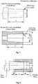
- the dimensions of male and female conical fittingsshall be as given in Table 1, below, and as shown in Figs. 1 and 2 .
- the conicityis 6 degrees according to the standard.
- the catheter 202is secured within an axial passageway in the distal hub section by means of a sleeve received within passageway, which engages the proximal end of the catheter 202.
- This passagewaycommunicates at its proximal end with interior cavity 204, which also acts as a flash chamber, formed in catheter hub 201.
- the distal end of the catheter 202may be tapered, to facilitate introduction into the vein of the patient.
- the needle unit 300 of the catheter instrument 1000comprises a needle hub 301.
- a needle 302extends distally from the needle hub 301.
- the needle hub 301may have an axial opening for receiving the proximal end zone of the needle 302.
- the needle 302comprises a needle shaft and a needle tip, said needle tip forming the distal end point of the needle unit 300.
- the needle hub 301may be hollow and may include a flash chamber at its proximal end.
- the needle 302is received within a hollow tubular catheter 202, the proximal end of which is concentrically affixed within the distal end of a catheter hub 201.
- the needle 302is provided with a bulge.
- the needle unit 300thus comprises a needle hub 301 and a needle 302 with a needle shaft and a needle tip extending distally from the needle hub 301.
- the proximal end of the catheter hub 201is snugly and releasably received in the distal end of the needle hub 301, such that the needle 302 extends through the cavity 204, the passageway and distally beyond the catheter hub 201 and catheter 202 so that the needle tip extends beyond a the distal end of the catheter 202.
- the needle hub 301is connected to the proximal end of the catheter hub 201 and said needle shaft is arranged in the lumen 203 of the catheter 202, in a ready position of said catheter instrument 1000.
- the needle hub 301may be connected to the proximal end of the catheter hub 201 and said needle shaft being arranged in the lumen 203 of the catheter 202, in a ready position of said catheter instrument 1000.
- the distal tip the needle 302 and the catheter 202are inserted into a patient's vein. Thereafter, the health care practitioner manually places the catheter 202 further into the vein and then withdraws the needle by grasping and moving by hand the proximal end of the needle unit 300.
- the luer of the catheter hub 200, in the proximal end of the cavity 204,is then fitted with a source of the fluid that is to be administered into the patient's vein.
- the spring clip needle tip shielding device 100is arranged inside the interior cavity 204 of the catheter hub 201.
- the spring clip needle tip shielding device 100comprises a base plate 101.
- the base plate 101is provided with a hole 102, extending there through, i.e. from the proximal side of the base plate 101 to the distal side of the base plate.
- the hole 102is arranged centrally on the base plate 101, such that arrangement of needle 302 through said hole 102 is facilitated while the needle 302 is arranged in accordance with the ready position of the catheter instrument 1000.
- a first resilient arm 103is extending distally from an attachment point at said base plate 101.
- the attachment pointis located at the periphery of the base plate 101.
- the resilient arm 103has a resting state, from which it may be urged to yield free passage for the needle 302 through said hole 102 in an axial direction of said base plate 101 in a tension state.
- the resilient arm 103is in its tension state when the catheter instrument 1000 is in its ready position.
- the resilient arm 103is adapted for clamping a needle tip of a needle 302 extending through the hole 102 when the resilient arm 103 is in said resting state.
- a straight imaginary line extending longitudinally through said hole 102 in the axial direction of said base plate 101coincides with said at least one resilient arm 103 when said resilient arm 103 is in said resting state.
- Thismay be facilitated by providing the resilient arm 103 with a distal hook element 104, at the distal end of the resilient arm 103.
- the spring clip needle tip shielding device 100may thus be arranged inside the interior cavity 204 of the catheter hub 201, and said needle being arranged through said hole 102 with the resilient arm 103 being urged into its tension state by said needle shaft.
- the spring clip needle tip shielding device 100is manufactured monolithically of a plastic material, with good flexibility and tension maintaining characteristics, such as polycarbonate, so as not to tear up the inner side of the catheter hub 201.
- the resilient arm 103is then dimensioned such that it may be flexed into its tension state when the catheter instrument 1000 is in its ready position.
- the needle unit 300is displaced proximally in relation to the catheter unit 200 and the spring clip needle tip shielding device 100.
- the spring clip needle tip shielding device 100is retained in the catheter hub 201 of the catheter unit 200 through interaction between the base plate 102, in accordance with above.
- the needle 302is displaced proximally in relation to these two.
- the bulge on the needle shaftthen hits the base plate 102, since the bulge has been dimensioned with a somewhat larger diameter than the through hole of the base plate 102. Also, the bulge has been positioned on the needle shaft at a distance from the needle tip largely corresponding to the distance between the base plate 102 and the distal end of the resilient arm 103, such that the spring clip needle tip shielding device 100 may be secured at the distal end of the needle 302 once the needle tip has been displaced proximally beyond the distal end, such as the hook element 104, of the spring clip needle tip shielding device 100. In this position, the spring clip needle tip shielding device 100 is released from the catheter unit 200 through overcoming the frictional force between the base plate 102 and the interior wall of the catheter hub 201, in accordance with above.
- the spring clip needle tip shielding device 100may be provided with more than one resilient arm 103.
- This additional resilient armmay also traverse the central axis of the catheter unit 200, and may thus also be provided with a through hole or a cut-out for letting the needle 301 pass there through.
- An additional resilient armmay further stabilize the positioning of the spring clip needle tip shielding device 100 on the needle shaft 300.
- the second resilient armmay be provided with a distal hook element for central displacement once the needle tip have passed proximally beyond the distal end of the first and second resilient arms 103.
- the spring clip shielding device 100is held in place in the catheter hub 201 through friction between the base plate 102 and the interior wall of the catheter hub 201.
- the base plate 102 of the spring clip needle tip shielding device 100is provided with tongues 105.
- the tongues 105may in turn be provided with cooperation knobs 106.
- the cooperation knobs 106extend laterally outwards from the base plate 102. In this way, the cooperation knobs 106 may flex somewhat to facilitate cooperation between the base plate 102, and thus the spring clip shielding device 100, and the catheter hub 200, and also compensate for discrepancies in shape between the base plate 102 and the lumen of the catheter hub.
- the interior cavity 204is provided with a cooperation groove 205.
- the cooperation groove 205is thus positioned within a distance from the proximal end, i.e. a proximal zone, of the catheter hub 201 of 0.75 mm (M, in Figs. 1 and 2 ), such as 0.5 mm, such as 0.45+/-0.05 mm.
- the cooperation groove 205extends radially in the interior cavity 204, i.e.
- the depth of the cooperation grooveis 0.05 to 0.1 mm, such as 0.06 to 0.08 mm.
- the term "comprises/comprising”does not exclude the presence of other elements or steps.
- a plurality of means, elements or method stepsmay be implemented by e.g. a single unit or processor.
- individual featuresmay be included in different claims, these may possibly advantageously be combined, and the inclusion in different claims does not imply that a combination of features is not feasible and/or advantageous.
- singular referencesdo not exclude a plurality.
- the terms “a”, “an”, “first”, “second” etcdo not preclude a plurality.
Landscapes
- Health & Medical Sciences (AREA)
- Life Sciences & Earth Sciences (AREA)
- Biophysics (AREA)
- Pulmonology (AREA)
- Engineering & Computer Science (AREA)
- Anesthesiology (AREA)
- Biomedical Technology (AREA)
- Heart & Thoracic Surgery (AREA)
- Hematology (AREA)
- Animal Behavior & Ethology (AREA)
- General Health & Medical Sciences (AREA)
- Public Health (AREA)
- Veterinary Medicine (AREA)
- Infusion, Injection, And Reservoir Apparatuses (AREA)
- Media Introduction/Drainage Providing Device (AREA)
Description
- The present invention relates to a catheter instrument, comprising a needle hub, a catheter hub, and a spring clip needle guard arranged in the catheter hub for the automatic safety shielding of a needle after its employment for introduction of a catheter tube into the vascular system of a patient. More specifically, the present invention pertains to a catheter hub for such a catheter instrument.
- The clinical utilization of a pointed hollow needle mounted inside a flexible catheter tube is well known in the medical art for the introduction of a catheter. In such a medical instrument, the catheter tube is positioned tightly around the needle in such a way as to allow the needle to slide and telescope along the length of the catheter tube. Before use, the tip of the needle is protruding slightly through the opening of the catheter tube to allow facile penetration through the skin. Upon puncturing of the skin and introduction of the needle, the distal end of the catheter tube is simultaneously brought into place inside the desired target body cavity of the patient, such as the inside of a blood vessel, for example a vein. The needle has then done its duty in assisting the introduction of the catheter and is withdrawn by being pulled backwards through the catheter. Upon release of the needle, the catheter is set in its intended working mode extending over a lengthier period of time and including, for example, periodical administration or infusion of fluids or medications in liquid form, the collection of blood samples and the like.
- An unprotected released needle constitutes, however, a serious health hazard due to the fact that it may be contaminated with e.g. infectious agents originating from the patient's blood or other body fluids, in combination with the needle tip's inherent ability to easily penetrate skin. Hence, the medical personnel who are handling the released needle may acquire the corresponding disease, e.g. HIV or hepatitis, if by accident contacting it with their skin. In order to circumvent or alleviate the health hazards associated with such a released needle amongst other things, there has been much effort devoted to the development of various kinds of needle tip protectors with a special focus on automatic variants of a type which may be referred to as being "foolproof".
EP 1 003 588 .discloses a safety IV catheter comprising a resilient spring clip normally positioned in the catheter hub. The needle of the safety IV catheter passes through a hole in the spring clip which allows axial movement of the needle. When the needle is in the forward position, i.e. when the safety IV catheter is ready for use, the presence of the needle forces parts of the spring clip into a position where these parts locks to the inside of the catheter hub, whereby movement of the spring clip relative the catheter hub is prevented. As the needle is withdrawn to a point where the tip passes these parts, the spring clip snaps into a position in which it is blocking access to the to the tip of the needle. Simultaneously, the part of the spring clip that previously locked to the inside of the catheter hub snap out of this position, whereby movement of the spring clip relative the catheter hub may occur. As the needle is further withdrawn, means are provided, e.g. a slot or a crimp on the needle, to lock the spring clip to the needle, whereby the spring clip is ejected from the catheter hub together with, and positioned on, the needle.- For various reasons, including e.g. practical, economical and technical reasons, the above described spring clips, and similar marketed variants, are today made of metal and catheter hubs of a plastic material. Disadvantages of the combination of these materials in this application include the release of e.g. microscopic plastic chips and metallic particles by the scraping of the metal spring clip against the inside of the plastic catheter hub when the former is ejected from the latter upon withdrawal of the needle. These chips and particles may easily be flushed into the bloodstream of a patient upon normal use of the corresponding catheter, and thus represent a serious health hazard to the same. This is especially true when the spring clip needs to pass beyond a bulge or something similar within the cavity of the catheter hub, onto which the metal spring clip should be brought into retained position until being released when the needle tip passes the distal part of the metal spring clip. Another disadvantage of the spring clip of this and similar safety IV catheters is the scraping vibration generated as the needle slides through and on the spring clip as it is withdrawn. This scraping vibration, which is due to metal sliding over metal and which can be clearly heard and felt, is highly uncomfortable and worrisome to the patient, who already is in an uncomfortable and exposed situation and may be very anxious.
- For these reasons attempts have been made to manufacture spring clips in materials not destroying the lumen of the catheter hub.
WO2013162461 discloses a spring clip of plastic material, said spring clip interacting with the lumen of the catheter hub through a base plate thereof, WO 2013/187827 discloses a catheter unit for use in an intravenous catheter instrument, wherein said catheter unit comprises a catheter hub and a catheter extending distally from the catheter hub according to the preamble of claim 1. However, there is a risk of the base plate interacting too much with the catheter hub lumen, since the tongues of the spring clip base plate will be in a tension state when arranged in the catheter hub. Therefore, it would be beneficial to develop a catheter instrument with less built-up tension in assembled state, to increase product reliability.- Accordingly, the present invention preferably seeks to mitigate, alleviate or eliminate one or more of the above-identified deficiencies in the art and disadvantages singly or in any combination and solves at least the above mentioned problems by providing a catheter unit for use in an intravenous catheter instrument, wherein said catheter unit comprises a catheter hub and a catheter extending distally from the catheter hub, said catheter having a lumen being in flow communication with an interior cavity of the catheter hub; wherein the interior cavity is provided with a cooperation groove at a proximal zone of the interior cavity.
- A catheter instrument, comprising such a catheter unit, is also provided, for the same purpose.
- Advantageous features of the invention are defined in the dependent claims.
- These and other aspects, features and advantages of which the invention is capable of will be apparent and elucidated from the following description of embodiments of the present invention, reference being made to the accompanying drawings, in which
Fig. 1 is a side view of a male luer fitting and a cross sectional view of a female fitting according to ISO standards;Fig. 2 is a side view of a male luer fitting and a cross sectional view of a female fitting according to ISO standards in cooperation;Fig. 3 is a perspective view of a catheter instrument according to the present invention, comprising a needle unit, a catheter unit, and a spring clip needle tip shielding device;Fig. 4 is a cross-sectional view of a catheter instrument according to the present invention, comprising a needle unit, a catheter unit, and a spring clip needle tip shielding device, and a close up thereof; andFig. 5 is a cross-sectional view of a catheter instrument according to the present invention, comprising a needle unit, a catheter unit, and a spring clip needle tip shielding device, and a close up thereof.- Embodiments of the present invention will be described in more detail below with reference to the accompanying
Figs. 1 and 2 in order for those skilled in the art to be able to carry out the invention. - The safety IV
catheter instrument 1000 includes a spring clip needletip shielding device 100, acatheter unit 200 and aneedle unit 300, in accordance withFigs. 3 to 5 . - The
catheter unit 200 comprises acatheter hub 201 and acatheter 202 extending distally from thecatheter hub 201. Thecatheter 202 is hollow and tubular, and configured to house a needle stem therein. Thecatheter 202 is made of a suitable polymeric material. Thecatheter hub 201 is also made of a suitable polymeric material, such as polypropylene or polyethylene, which are cheap plastic materials with good injection molding properties. The hollow and tubular configuration of thecatheter 202 provides alumen 203 that is in flow communication with aninterior cavity 204 of thecatheter hub 201. Theinterior cavity 204 is positioned in the proximal end of thecatheter hub 201, and the proximal opening into theinterior cavity 204 may end in a luer fitting, such as a luer lock or luer slip, adapted to receive a tubing set, which in a known manner, administers intravenous fluid into the patient. Thecatheter unit 200 thus comprises acatheter hub 201 and acatheter 202 extending distally from thecatheter hub 201, saidcatheter 202 having alumen 203 being in flow communication with aninterior cavity 204 of thecatheter hub 201. - The
interior cavity 204 has to follow international standards (such as ISO 594/1-1986) in respect of luer fittings. The dimensions of male and female conical fittings shall be as given in Table 1, below, and as shown inFigs. 1 and 2 . The conicity is 6 degrees according to the standard.
- The
catheter 202 is secured within an axial passageway in the distal hub section by means of a sleeve received within passageway, which engages the proximal end of thecatheter 202. This passageway communicates at its proximal end withinterior cavity 204, which also acts as a flash chamber, formed incatheter hub 201. The distal end of thecatheter 202 may be tapered, to facilitate introduction into the vein of the patient. - The
needle unit 300 of thecatheter instrument 1000 comprises aneedle hub 301. Aneedle 302 extends distally from theneedle hub 301. Theneedle hub 301 may have an axial opening for receiving the proximal end zone of theneedle 302. Theneedle 302 comprises a needle shaft and a needle tip, said needle tip forming the distal end point of theneedle unit 300. Theneedle hub 301, as is conventional, may be hollow and may include a flash chamber at its proximal end. As is also conventional, theneedle 302 is received within a hollowtubular catheter 202, the proximal end of which is concentrically affixed within the distal end of acatheter hub 201. At the distal end zone of the needle shaft, theneedle 302 is provided with a bulge. Theneedle unit 300 thus comprises aneedle hub 301 and aneedle 302 with a needle shaft and a needle tip extending distally from theneedle hub 301. - In the ready position of the
catheter instrument 1000, the proximal end of thecatheter hub 201 is snugly and releasably received in the distal end of theneedle hub 301, such that theneedle 302 extends through thecavity 204, the passageway and distally beyond thecatheter hub 201 andcatheter 202 so that the needle tip extends beyond a the distal end of thecatheter 202. Thus, theneedle hub 301 is connected to the proximal end of thecatheter hub 201 and said needle shaft is arranged in thelumen 203 of thecatheter 202, in a ready position of saidcatheter instrument 1000. Theneedle hub 301 may be connected to the proximal end of thecatheter hub 201 and said needle shaft being arranged in thelumen 203 of thecatheter 202, in a ready position of saidcatheter instrument 1000. - In use, the distal tip the
needle 302 and thecatheter 202 are inserted into a patient's vein. Thereafter, the health care practitioner manually places thecatheter 202 further into the vein and then withdraws the needle by grasping and moving by hand the proximal end of theneedle unit 300. The luer of thecatheter hub 200, in the proximal end of thecavity 204, is then fitted with a source of the fluid that is to be administered into the patient's vein. - The spring clip needle
tip shielding device 100 is arranged inside theinterior cavity 204 of thecatheter hub 201. The spring clip needletip shielding device 100 comprises abase plate 101. Thebase plate 101 is provided with ahole 102, extending there through, i.e. from the proximal side of thebase plate 101 to the distal side of the base plate. Preferably, thehole 102 is arranged centrally on thebase plate 101, such that arrangement ofneedle 302 through saidhole 102 is facilitated while theneedle 302 is arranged in accordance with the ready position of thecatheter instrument 1000. - A first
resilient arm 103 is extending distally from an attachment point at saidbase plate 101. Preferably, due to manufacturing reasons, the attachment point is located at the periphery of thebase plate 101. Theresilient arm 103 has a resting state, from which it may be urged to yield free passage for theneedle 302 through saidhole 102 in an axial direction of saidbase plate 101 in a tension state. Theresilient arm 103 is in its tension state when thecatheter instrument 1000 is in its ready position. Theresilient arm 103 is adapted for clamping a needle tip of aneedle 302 extending through thehole 102 when theresilient arm 103 is in said resting state. For this reason, a straight imaginary line extending longitudinally through saidhole 102 in the axial direction of saidbase plate 101 coincides with said at least oneresilient arm 103 when saidresilient arm 103 is in said resting state. This may be facilitated by providing theresilient arm 103 with adistal hook element 104, at the distal end of theresilient arm 103. The spring clip needletip shielding device 100 may thus be arranged inside theinterior cavity 204 of thecatheter hub 201, and said needle being arranged through saidhole 102 with theresilient arm 103 being urged into its tension state by said needle shaft. - The spring clip needle
tip shielding device 100 is manufactured monolithically of a plastic material, with good flexibility and tension maintaining characteristics, such as polycarbonate, so as not to tear up the inner side of thecatheter hub 201. Theresilient arm 103 is then dimensioned such that it may be flexed into its tension state when thecatheter instrument 1000 is in its ready position. - After the distal tip of the
needle 302 and thecatheter 202 have been inserted into a patient's vein, theneedle unit 300 is displaced proximally in relation to thecatheter unit 200 and the spring clip needletip shielding device 100. The spring clip needletip shielding device 100 is retained in thecatheter hub 201 of thecatheter unit 200 through interaction between thebase plate 102, in accordance with above. When theneedle unit 300 is displaced proximally in relation to thecatheter unit 200 and the spring clip needletip shielding device 100, also theneedle 302 is displaced proximally in relation to these two. Once the needle tip passes proximally beyond the distal end of theresilient arm 103, such as thehook element 104, the distal end of theresilient arm 103 snaps in front of the needle tip. The bulge on the needle shaft then hits thebase plate 102, since the bulge has been dimensioned with a somewhat larger diameter than the through hole of thebase plate 102. Also, the bulge has been positioned on the needle shaft at a distance from the needle tip largely corresponding to the distance between thebase plate 102 and the distal end of theresilient arm 103, such that the spring clip needletip shielding device 100 may be secured at the distal end of theneedle 302 once the needle tip has been displaced proximally beyond the distal end, such as thehook element 104, of the spring clip needletip shielding device 100. In this position, the spring clip needletip shielding device 100 is released from thecatheter unit 200 through overcoming the frictional force between thebase plate 102 and the interior wall of thecatheter hub 201, in accordance with above. - The spring clip needle
tip shielding device 100 may be provided with more than oneresilient arm 103. This additional resilient arm may also traverse the central axis of thecatheter unit 200, and may thus also be provided with a through hole or a cut-out for letting theneedle 301 pass there through. An additional resilient arm may further stabilize the positioning of the spring clip needletip shielding device 100 on theneedle shaft 300. Also the second resilient arm may be provided with a distal hook element for central displacement once the needle tip have passed proximally beyond the distal end of the first and secondresilient arms 103. - The spring
clip shielding device 100 is held in place in thecatheter hub 201 through friction between thebase plate 102 and the interior wall of thecatheter hub 201. Thebase plate 102 of the spring clip needletip shielding device 100 is provided withtongues 105. Thetongues 105 may in turn be provided withcooperation knobs 106. The cooperation knobs 106 extend laterally outwards from thebase plate 102. In this way, the cooperation knobs 106 may flex somewhat to facilitate cooperation between thebase plate 102, and thus the springclip shielding device 100, and thecatheter hub 200, and also compensate for discrepancies in shape between thebase plate 102 and the lumen of the catheter hub. - In a luer fitting, according to the standard indicated above in Table 1 and
Fig. 1 , there is a tolerance M. This tolerance M may be used for further improving engagement between thebase plate 102 of the springclip shielding device 100 and theinterior cavity 204 of thecatheter hub 201. For this reason, theinterior cavity 204 is provided with acooperation groove 205. Thecooperation groove 205 is thus positioned within a distance from the proximal end, i.e. a proximal zone, of thecatheter hub 201 of 0.75 mm (M, inFigs. 1 and 2 ), such as 0.5 mm, such as 0.45+/-0.05 mm. Thecooperation groove 205 extends radially in theinterior cavity 204, i.e. on the inside of thecatheter hub 201. The depth of the cooperation groove is 0.05 to 0.1 mm, such as 0.06 to 0.08 mm. When receiving the springclip shielding device 100 in theinterior cavity 204 of thecatheter hub 201, the cooperation knobs 106 on thetongues 105 will snap into cooperation with thecatheter hub 200 through first being urged centrally when being pushed distally into the catheter hub, to thereafter relax to snap into thecooperation groove 205, as disclosed inFig. 4 . In this way, theknobs 106, and therebytongues 105 and springclip shielding device 100, will be in a more relaxed state in mounted position, whereby the risk of plastic-to-plastic migration is relieved - hence improving long-term storing of thecatheter instrument 1000. - It is also possible to dimension the relationship between the
groove 205,tongues 105 and theknobs 106, such that thetongues 105 andknobs 106 are in a more relaxed state, but still in physical contact with thegroove 205, as disclosed inFig. 5 . - Although the present invention has been described above with reference to specific embodiments, it is not intended to be limited to the specific form set forth herein. Rather, the invention is limited only by the accompanying claims and, other embodiments than the specific above are equally possible within the scope of these appended claims.
- In the claims, the term "comprises/comprising" does not exclude the presence of other elements or steps. Furthermore, although individually listed, a plurality of means, elements or method steps may be implemented by e.g. a single unit or processor. Additionally, although individual features may be included in different claims, these may possibly advantageously be combined, and the inclusion in different claims does not imply that a combination of features is not feasible and/or advantageous. In addition, singular references do not exclude a plurality. The terms "a", "an", "first", "second" etc do not preclude a plurality.

Claims (6)
- A catheter unit (200) for use in an intravenous catheter instrument (1000), wherein said catheter unit (200) comprises a catheter hub (201) and a catheter (202) extending distally from the catheter hub (201), said catheter (202) having a lumen (203) being in flow communication with an interior cavity (204) of the catheter hub (201);
characterized in that
the interior cavity (204) is provided with a cooperation groove (205) at a proximal zone of the interior cavity (204);
wherein the proximal zone extends distally 0.75 mm from a proximal end of the interior cavity (204). - The catheter unit (200) according to claim 1, wherein the proximal zone extends distally 0.45+/-0.05 mm from a proximal end of the interior cavity (204).
- The catheter unit (200) according to any of the preceding claims, wherein the depth of the cooperation groove (205) is 0.05 to 0.1 mm.
- The catheter unit (200) according to any of the preceding claims, wherein the cooperation groove (205) extends radially in form of a ring on the inside of the catheter hub (201).
- A catheter instrument (1000) comprising a catheter unit (200) according to any of claims 1 to 4, a spring clip needle tip shielding device (100) and a needle unit (300);
wherein the spring clip needle tip shielding device (100) comprises: a base plate (101) with a hole (102) extending there through; at least one resilient arm (103) extending at an attachment point at said base plate (101); wherein said at least one resilient arm (103) has a resting state, from which it may be urged to yield free passage through said hole (102) in an axial direction of said base plate (101) in a tension state, said at least one resilient arm (103) being adapted for clamping a needle tip of a needle (301) extending through said hole (102) when said resilient arm (103) is in said resting state;
wherein said needle unit (300) comprises a needle hub (301) and a needle (302) with a needle shaft and a needle tip extending distally from the needle hub (301);
said needle hub (301) being connected to the proximal end of the catheter hub (201) and said needle shaft being arranged in the lumen (203) of the catheter (202), in a ready position of said catheter instrument (1000), and
said spring clip needle tip shielding device (100) being arranged inside the interior cavity (204) of the catheter hub (201), and said needle being arranged through said hole (102) with the resilient arm (103) being urged into its tension state by said needle shaft. - The catheter instrument (1000) according to claim 5, wherein tongues (105) with knobs (106) on said base plate (102) cooperate releasably with the cooperation groove (205).
Applications Claiming Priority (2)
| Application Number | Priority Date | Filing Date | Title |
|---|---|---|---|
| SE1450499 | 2014-04-28 | ||
| PCT/SE2015/050266WO2015167385A1 (en) | 2014-04-28 | 2015-03-10 | Catheter instrument and catheter hub therefore |
Publications (3)
| Publication Number | Publication Date |
|---|---|
| EP3137147A1 EP3137147A1 (en) | 2017-03-08 |
| EP3137147A4 EP3137147A4 (en) | 2017-12-27 |
| EP3137147B1true EP3137147B1 (en) | 2019-06-19 |
Family
ID=54358967
Family Applications (1)
| Application Number | Title | Priority Date | Filing Date |
|---|---|---|---|
| EP15786000.8AActiveEP3137147B1 (en) | 2014-04-28 | 2015-03-10 | Catheter instrument and catheter hub therefore |
Country Status (5)
| Country | Link |
|---|---|
| US (1) | US20170043135A1 (en) |
| EP (1) | EP3137147B1 (en) |
| CN (1) | CN106456934B (en) |
| ES (1) | ES2744601T3 (en) |
| WO (1) | WO2015167385A1 (en) |
Families Citing this family (17)
| Publication number | Priority date | Publication date | Assignee | Title |
|---|---|---|---|---|
| WO2017151052A1 (en)* | 2016-03-04 | 2017-09-08 | Vigmed Ab | Blood collection device |
| EP3528723B1 (en) | 2016-10-27 | 2023-08-16 | C. R. Bard, Inc. | Intraosseous access device |
| AU2017373953B2 (en) | 2016-12-08 | 2023-05-11 | Abiomed, Inc. | Overmold technique for peel-away introducer design |
| KR102452113B1 (en) | 2017-11-06 | 2022-10-07 | 아비오메드, 인크. | Separable hemostatic valve |
| US10828467B2 (en) | 2017-11-30 | 2020-11-10 | Becton, Dickinson And Company | Catheter assembly |
| ES2991910T3 (en) | 2018-05-16 | 2024-12-05 | Abiomed Inc | Removable cover set |
| US11759235B2 (en) | 2019-09-27 | 2023-09-19 | Bard Access Systems, Inc. | Constant-torque intraosseous access devices and methods thereof |
| CN212879457U (en) | 2019-09-27 | 2021-04-06 | 巴德阿克塞斯系统股份有限公司 | Self-advancing intraosseous access device and intraosseous access device |
| CN212879505U (en) | 2019-09-27 | 2021-04-06 | 巴德阿克塞斯系统股份有限公司 | Intraosseous access device |
| WO2021062215A1 (en) | 2019-09-27 | 2021-04-01 | Bard Access Systems, Inc. | Step needle for intraosseous access device |
| CN113317840A (en) | 2020-02-28 | 2021-08-31 | 巴德阿克塞斯系统股份有限公司 | Flexible intra-osseous obturator |
| WO2021216521A1 (en) | 2020-04-21 | 2021-10-28 | Bard Access Systems , Inc. | Reusable push-activated intraosseous access device |
| CN113749724A (en) | 2020-06-03 | 2021-12-07 | 巴德阿克塞斯系统股份有限公司 | Intraosseous device including sensing obturator |
| CN216167681U (en) | 2020-07-17 | 2022-04-05 | 巴德阿克塞斯系统股份有限公司 | Safety mechanism |
| CN216628654U (en) | 2020-08-25 | 2022-05-31 | 巴德阿克塞斯系统股份有限公司 | Angled intraosseous access system |
| CN215839325U (en) | 2020-09-09 | 2022-02-18 | 巴德阿克塞斯系统股份有限公司 | Suction device for an intraosseous access system |
| CN217960227U (en) | 2021-02-08 | 2022-12-06 | 巴德阿克塞斯系统股份有限公司 | Intraosseous access system |
Family Cites Families (20)
| Publication number | Priority date | Publication date | Assignee | Title |
|---|---|---|---|---|
| US4160450A (en)* | 1977-07-15 | 1979-07-10 | Doherty George O | Outside-the-needle catheter device with needle housing |
| US8382721B2 (en)* | 1997-08-20 | 2013-02-26 | B. Braun Melsungen Ag | Spring clip safety IV catheter |
| US6117108A (en)* | 1997-08-20 | 2000-09-12 | Braun Melsungen Ag | Spring clip safety IV catheter |
| DE20103363U1 (en)* | 2001-02-26 | 2001-05-17 | Braun Melsungen Ag | Protection device for an injection needle |
| US6595954B1 (en)* | 2000-03-13 | 2003-07-22 | Luther Research Partners, Llc | Insertion needle and soft catheter system with tip protector |
| US20040049155A1 (en)* | 2002-06-06 | 2004-03-11 | Schramm John B. | Needle tip protector |
| US20050075609A1 (en)* | 2003-10-01 | 2005-04-07 | Latona Patrick C. | Protective needle clips |
| US7699818B2 (en)* | 2005-02-08 | 2010-04-20 | Paul J. Gilbert | Insertion system and methods for nasogastric tubes |
| US8403886B2 (en)* | 2005-08-08 | 2013-03-26 | Smiths Medical Asd, Inc. | Needle guard clip with lip |
| US8257313B2 (en)* | 2006-08-11 | 2012-09-04 | Becton, Dickinson And Company | Integrated septum and needle tip shield for a catheter assembly |
| US8992483B2 (en)* | 2007-03-27 | 2015-03-31 | Nipro Corporation | Indwelling needle assembly and protector |
| EP2279770B1 (en)* | 2007-07-17 | 2012-07-11 | Poly Medicure Ltd. | Needle |
| SE534021C2 (en)* | 2009-08-13 | 2011-04-05 | Vigmed Ab | Protective device for a catheter needle tip |
| SE535169C2 (en)* | 2010-04-13 | 2012-05-08 | Vigmed Ab | Polymer protective device for a catheter needle tip |
| RU2729036C2 (en)* | 2010-08-05 | 2020-08-03 | Б. Браун Мельзунген Аг | Safe needle device and assembly |
| ES2721902T5 (en)* | 2010-09-23 | 2023-06-28 | Greiner Bio One Gmbh | Needle tip protection device |
| CN202699833U (en)* | 2011-02-09 | 2013-01-30 | 威格米德公司 | Needle tip protection device and catheter device |
| IN2012DE00486A (en)* | 2012-02-21 | 2015-06-05 | Poly Medicure Ltd | |
| SE537334C2 (en)* | 2012-04-27 | 2015-04-07 | Vigmed Ab | Protective device for needle point and mounting device |
| SE537262C2 (en)* | 2012-06-15 | 2015-03-17 | Vigmed Ab | A closed IV catheter system comprising a needle guard device |
- 2015
- 2015-03-10EPEP15786000.8Apatent/EP3137147B1/enactiveActive
- 2015-03-10ESES15786000Tpatent/ES2744601T3/enactiveActive
- 2015-03-10WOPCT/SE2015/050266patent/WO2015167385A1/enactiveApplication Filing
- 2015-03-10CNCN201580019943.1Apatent/CN106456934B/enactiveActive
- 2015-03-10USUS15/307,279patent/US20170043135A1/ennot_activeAbandoned
Non-Patent Citations (1)
| Title |
|---|
| None* |
Also Published As
| Publication number | Publication date |
|---|---|
| EP3137147A4 (en) | 2017-12-27 |
| WO2015167385A1 (en) | 2015-11-05 |
| EP3137147A1 (en) | 2017-03-08 |
| CN106456934B (en) | 2020-04-28 |
| US20170043135A1 (en) | 2017-02-16 |
| CN106456934A (en) | 2017-02-22 |
| ES2744601T3 (en) | 2020-02-25 |
Similar Documents
| Publication | Publication Date | Title |
|---|---|---|
| EP3137147B1 (en) | Catheter instrument and catheter hub therefore | |
| EP2941289B2 (en) | Spring clip needle guard | |
| US11202887B2 (en) | Needle tip shielding device and catheter hub therefore | |
| AU2017375773B2 (en) | Safety needle device | |
| US11406794B2 (en) | Needle hub and IV catheter system comprising such needle hub | |
| US7291130B2 (en) | Safety needle and catheter assembly | |
| US9358348B2 (en) | Safety shield for medical needles | |
| CA2405331C (en) | Safety catheter | |
| EP0830872B1 (en) | Motion lock for insertion needle of a safety catheter | |
| AU2006202547B2 (en) | Safety shield for medical needles | |
| MXPA01003878A (en) | Releasable locking needle assembly with optional release accessory therefor. | |
| JP2933652B2 (en) | Needle penetrating catheter device and insertion method thereof | |
| CA2520353C (en) | Safety needle and catheter assembly | |
| CN112292079A (en) | Squeeze Actuated Blood Collection Kit | |
| HK1234683A1 (en) | Catheter instrument and catheter hub therefor |
Legal Events
| Date | Code | Title | Description |
|---|---|---|---|
| STAA | Information on the status of an ep patent application or granted ep patent | Free format text:STATUS: THE INTERNATIONAL PUBLICATION HAS BEEN MADE | |
| PUAI | Public reference made under article 153(3) epc to a published international application that has entered the european phase | Free format text:ORIGINAL CODE: 0009012 | |
| STAA | Information on the status of an ep patent application or granted ep patent | Free format text:STATUS: REQUEST FOR EXAMINATION WAS MADE | |
| 17P | Request for examination filed | Effective date:20160922 | |
| AK | Designated contracting states | Kind code of ref document:A1 Designated state(s):AL AT BE BG CH CY CZ DE DK EE ES FI FR GB GR HR HU IE IS IT LI LT LU LV MC MK MT NL NO PL PT RO RS SE SI SK SM TR | |
| AX | Request for extension of the european patent | Extension state:BA ME | |
| DAV | Request for validation of the european patent (deleted) | ||
| DAX | Request for extension of the european patent (deleted) | ||
| A4 | Supplementary search report drawn up and despatched | Effective date:20171128 | |
| RIC1 | Information provided on ipc code assigned before grant | Ipc:A61M 25/06 20060101ALI20171122BHEP Ipc:A61M 39/10 20060101ALI20171122BHEP Ipc:A61M 25/00 20060101AFI20171122BHEP | |
| GRAP | Despatch of communication of intention to grant a patent | Free format text:ORIGINAL CODE: EPIDOSNIGR1 | |
| STAA | Information on the status of an ep patent application or granted ep patent | Free format text:STATUS: GRANT OF PATENT IS INTENDED | |
| INTG | Intention to grant announced | Effective date:20190307 | |
| GRAS | Grant fee paid | Free format text:ORIGINAL CODE: EPIDOSNIGR3 | |
| GRAA | (expected) grant | Free format text:ORIGINAL CODE: 0009210 | |
| STAA | Information on the status of an ep patent application or granted ep patent | Free format text:STATUS: THE PATENT HAS BEEN GRANTED | |
| AK | Designated contracting states | Kind code of ref document:B1 Designated state(s):AL AT BE BG CH CY CZ DE DK EE ES FI FR GB GR HR HU IE IS IT LI LT LU LV MC MK MT NL NO PL PT RO RS SE SI SK SM TR | |
| REG | Reference to a national code | Ref country code:GB Ref legal event code:FG4D | |
| REG | Reference to a national code | Ref country code:CH Ref legal event code:EP | |
| REG | Reference to a national code | Ref country code:IE Ref legal event code:FG4D | |
| REG | Reference to a national code | Ref country code:DE Ref legal event code:R096 Ref document number:602015032351 Country of ref document:DE | |
| REG | Reference to a national code | Ref country code:AT Ref legal event code:REF Ref document number:1144695 Country of ref document:AT Kind code of ref document:T Effective date:20190715 | |
| REG | Reference to a national code | Ref country code:SE Ref legal event code:TRGR | |
| REG | Reference to a national code | Ref country code:NL Ref legal event code:MP Effective date:20190619 | |
| PG25 | Lapsed in a contracting state [announced via postgrant information from national office to epo] | Ref country code:HR Free format text:LAPSE BECAUSE OF FAILURE TO SUBMIT A TRANSLATION OF THE DESCRIPTION OR TO PAY THE FEE WITHIN THE PRESCRIBED TIME-LIMIT Effective date:20190619 Ref country code:LT Free format text:LAPSE BECAUSE OF FAILURE TO SUBMIT A TRANSLATION OF THE DESCRIPTION OR TO PAY THE FEE WITHIN THE PRESCRIBED TIME-LIMIT Effective date:20190619 Ref country code:AL Free format text:LAPSE BECAUSE OF FAILURE TO SUBMIT A TRANSLATION OF THE DESCRIPTION OR TO PAY THE FEE WITHIN THE PRESCRIBED TIME-LIMIT Effective date:20190619 Ref country code:NO Free format text:LAPSE BECAUSE OF FAILURE TO SUBMIT A TRANSLATION OF THE DESCRIPTION OR TO PAY THE FEE WITHIN THE PRESCRIBED TIME-LIMIT Effective date:20190919 Ref country code:FI Free format text:LAPSE BECAUSE OF FAILURE TO SUBMIT A TRANSLATION OF THE DESCRIPTION OR TO PAY THE FEE WITHIN THE PRESCRIBED TIME-LIMIT Effective date:20190619 | |
| REG | Reference to a national code | Ref country code:LT Ref legal event code:MG4D | |
| PG25 | Lapsed in a contracting state [announced via postgrant information from national office to epo] | Ref country code:BG Free format text:LAPSE BECAUSE OF FAILURE TO SUBMIT A TRANSLATION OF THE DESCRIPTION OR TO PAY THE FEE WITHIN THE PRESCRIBED TIME-LIMIT Effective date:20190919 Ref country code:LV Free format text:LAPSE BECAUSE OF FAILURE TO SUBMIT A TRANSLATION OF THE DESCRIPTION OR TO PAY THE FEE WITHIN THE PRESCRIBED TIME-LIMIT Effective date:20190619 Ref country code:RS Free format text:LAPSE BECAUSE OF FAILURE TO SUBMIT A TRANSLATION OF THE DESCRIPTION OR TO PAY THE FEE WITHIN THE PRESCRIBED TIME-LIMIT Effective date:20190619 Ref country code:GR Free format text:LAPSE BECAUSE OF FAILURE TO SUBMIT A TRANSLATION OF THE DESCRIPTION OR TO PAY THE FEE WITHIN THE PRESCRIBED TIME-LIMIT Effective date:20190920 | |
| PG25 | Lapsed in a contracting state [announced via postgrant information from national office to epo] | Ref country code:NL Free format text:LAPSE BECAUSE OF FAILURE TO SUBMIT A TRANSLATION OF THE DESCRIPTION OR TO PAY THE FEE WITHIN THE PRESCRIBED TIME-LIMIT Effective date:20190619 Ref country code:RO Free format text:LAPSE BECAUSE OF FAILURE TO SUBMIT A TRANSLATION OF THE DESCRIPTION OR TO PAY THE FEE WITHIN THE PRESCRIBED TIME-LIMIT Effective date:20190619 Ref country code:SK Free format text:LAPSE BECAUSE OF FAILURE TO SUBMIT A TRANSLATION OF THE DESCRIPTION OR TO PAY THE FEE WITHIN THE PRESCRIBED TIME-LIMIT Effective date:20190619 Ref country code:CZ Free format text:LAPSE BECAUSE OF FAILURE TO SUBMIT A TRANSLATION OF THE DESCRIPTION OR TO PAY THE FEE WITHIN THE PRESCRIBED TIME-LIMIT Effective date:20190619 Ref country code:EE Free format text:LAPSE BECAUSE OF FAILURE TO SUBMIT A TRANSLATION OF THE DESCRIPTION OR TO PAY THE FEE WITHIN THE PRESCRIBED TIME-LIMIT Effective date:20190619 Ref country code:PT Free format text:LAPSE BECAUSE OF FAILURE TO SUBMIT A TRANSLATION OF THE DESCRIPTION OR TO PAY THE FEE WITHIN THE PRESCRIBED TIME-LIMIT Effective date:20191021 | |
| REG | Reference to a national code | Ref country code:ES Ref legal event code:FG2A Ref document number:2744601 Country of ref document:ES Kind code of ref document:T3 Effective date:20200225 | |
| PG25 | Lapsed in a contracting state [announced via postgrant information from national office to epo] | Ref country code:IS Free format text:LAPSE BECAUSE OF FAILURE TO SUBMIT A TRANSLATION OF THE DESCRIPTION OR TO PAY THE FEE WITHIN THE PRESCRIBED TIME-LIMIT Effective date:20191019 Ref country code:SM Free format text:LAPSE BECAUSE OF FAILURE TO SUBMIT A TRANSLATION OF THE DESCRIPTION OR TO PAY THE FEE WITHIN THE PRESCRIBED TIME-LIMIT Effective date:20190619 | |
| PG25 | Lapsed in a contracting state [announced via postgrant information from national office to epo] | Ref country code:TR Free format text:LAPSE BECAUSE OF FAILURE TO SUBMIT A TRANSLATION OF THE DESCRIPTION OR TO PAY THE FEE WITHIN THE PRESCRIBED TIME-LIMIT Effective date:20190619 | |
| PG25 | Lapsed in a contracting state [announced via postgrant information from national office to epo] | Ref country code:PL Free format text:LAPSE BECAUSE OF FAILURE TO SUBMIT A TRANSLATION OF THE DESCRIPTION OR TO PAY THE FEE WITHIN THE PRESCRIBED TIME-LIMIT Effective date:20190619 Ref country code:DK Free format text:LAPSE BECAUSE OF FAILURE TO SUBMIT A TRANSLATION OF THE DESCRIPTION OR TO PAY THE FEE WITHIN THE PRESCRIBED TIME-LIMIT Effective date:20190619 | |
| PG25 | Lapsed in a contracting state [announced via postgrant information from national office to epo] | Ref country code:IS Free format text:LAPSE BECAUSE OF FAILURE TO SUBMIT A TRANSLATION OF THE DESCRIPTION OR TO PAY THE FEE WITHIN THE PRESCRIBED TIME-LIMIT Effective date:20200224 | |
| REG | Reference to a national code | Ref country code:DE Ref legal event code:R097 Ref document number:602015032351 Country of ref document:DE | |
| PLBE | No opposition filed within time limit | Free format text:ORIGINAL CODE: 0009261 | |
| STAA | Information on the status of an ep patent application or granted ep patent | Free format text:STATUS: NO OPPOSITION FILED WITHIN TIME LIMIT | |
| PG2D | Information on lapse in contracting state deleted | Ref country code:IS | |
| 26N | No opposition filed | Effective date:20200603 | |
| REG | Reference to a national code | Ref country code:AT Ref legal event code:UEP Ref document number:1144695 Country of ref document:AT Kind code of ref document:T Effective date:20190619 | |
| PG25 | Lapsed in a contracting state [announced via postgrant information from national office to epo] | Ref country code:SI Free format text:LAPSE BECAUSE OF FAILURE TO SUBMIT A TRANSLATION OF THE DESCRIPTION OR TO PAY THE FEE WITHIN THE PRESCRIBED TIME-LIMIT Effective date:20190619 | |
| PG25 | Lapsed in a contracting state [announced via postgrant information from national office to epo] | Ref country code:MC Free format text:LAPSE BECAUSE OF FAILURE TO SUBMIT A TRANSLATION OF THE DESCRIPTION OR TO PAY THE FEE WITHIN THE PRESCRIBED TIME-LIMIT Effective date:20190619 | |
| REG | Reference to a national code | Ref country code:CH Ref legal event code:PL | |
| REG | Reference to a national code | Ref country code:BE Ref legal event code:MM Effective date:20200331 | |
| PG25 | Lapsed in a contracting state [announced via postgrant information from national office to epo] | Ref country code:LU Free format text:LAPSE BECAUSE OF NON-PAYMENT OF DUE FEES Effective date:20200310 | |
| PG25 | Lapsed in a contracting state [announced via postgrant information from national office to epo] | Ref country code:IE Free format text:LAPSE BECAUSE OF NON-PAYMENT OF DUE FEES Effective date:20200310 Ref country code:LI Free format text:LAPSE BECAUSE OF NON-PAYMENT OF DUE FEES Effective date:20200331 Ref country code:CH Free format text:LAPSE BECAUSE OF NON-PAYMENT OF DUE FEES Effective date:20200331 | |
| PG25 | Lapsed in a contracting state [announced via postgrant information from national office to epo] | Ref country code:BE Free format text:LAPSE BECAUSE OF NON-PAYMENT OF DUE FEES Effective date:20200331 | |
| REG | Reference to a national code | Ref country code:GB Ref legal event code:732E Free format text:REGISTERED BETWEEN 20220120 AND 20220126 | |
| PG25 | Lapsed in a contracting state [announced via postgrant information from national office to epo] | Ref country code:MT Free format text:LAPSE BECAUSE OF FAILURE TO SUBMIT A TRANSLATION OF THE DESCRIPTION OR TO PAY THE FEE WITHIN THE PRESCRIBED TIME-LIMIT Effective date:20190619 Ref country code:CY Free format text:LAPSE BECAUSE OF FAILURE TO SUBMIT A TRANSLATION OF THE DESCRIPTION OR TO PAY THE FEE WITHIN THE PRESCRIBED TIME-LIMIT Effective date:20190619 | |
| PG25 | Lapsed in a contracting state [announced via postgrant information from national office to epo] | Ref country code:MK Free format text:LAPSE BECAUSE OF FAILURE TO SUBMIT A TRANSLATION OF THE DESCRIPTION OR TO PAY THE FEE WITHIN THE PRESCRIBED TIME-LIMIT Effective date:20190619 | |
| REG | Reference to a national code | Ref country code:ES Ref legal event code:PC2A Owner name:GREINER BIO-ONE GMBH Effective date:20220705 | |
| REG | Reference to a national code | Ref country code:DE Ref legal event code:R081 Ref document number:602015032351 Country of ref document:DE Owner name:GREINER BIO-ONE GMBH, AT Free format text:FORMER OWNER: VIGMED AB, HELSINGBORG, SE | |
| P01 | Opt-out of the competence of the unified patent court (upc) registered | Effective date:20230526 | |
| PGFP | Annual fee paid to national office [announced via postgrant information from national office to epo] | Ref country code:SE Payment date:20250311 Year of fee payment:11 | |
| PGFP | Annual fee paid to national office [announced via postgrant information from national office to epo] | Ref country code:DE Payment date:20250320 Year of fee payment:11 | |
| PGFP | Annual fee paid to national office [announced via postgrant information from national office to epo] | Ref country code:AT Payment date:20250321 Year of fee payment:11 | |
| PGFP | Annual fee paid to national office [announced via postgrant information from national office to epo] | Ref country code:FR Payment date:20250325 Year of fee payment:11 | |
| PGFP | Annual fee paid to national office [announced via postgrant information from national office to epo] | Ref country code:IT Payment date:20250306 Year of fee payment:11 Ref country code:GB Payment date:20250324 Year of fee payment:11 | |
| PGFP | Annual fee paid to national office [announced via postgrant information from national office to epo] | Ref country code:ES Payment date:20250403 Year of fee payment:11 |