EP3136998B1 - Tissue resectors with cutting wires and hand-operated tissue resector systems - Google Patents
Tissue resectors with cutting wires and hand-operated tissue resector systemsDownload PDFInfo
- Publication number
- EP3136998B1 EP3136998B1EP15785861.4AEP15785861AEP3136998B1EP 3136998 B1EP3136998 B1EP 3136998B1EP 15785861 AEP15785861 AEP 15785861AEP 3136998 B1EP3136998 B1EP 3136998B1
- Authority
- EP
- European Patent Office
- Prior art keywords
- cannula
- tissue
- opening
- cutting wire
- cutting
- Prior art date
- Legal status (The legal status is an assumption and is not a legal conclusion. Google has not performed a legal analysis and makes no representation as to the accuracy of the status listed.)
- Active
Links
Images


Classifications
- A—HUMAN NECESSITIES
- A61—MEDICAL OR VETERINARY SCIENCE; HYGIENE
- A61B—DIAGNOSIS; SURGERY; IDENTIFICATION
- A61B17/00—Surgical instruments, devices or methods
- A61B17/32—Surgical cutting instruments
- A61B17/320016—Endoscopic cutting instruments, e.g. arthroscopes, resectoscopes
- A61B17/32002—Endoscopic cutting instruments, e.g. arthroscopes, resectoscopes with continuously rotating, oscillating or reciprocating cutting instruments
- A61B2017/320024—Morcellators, e.g. having a hollow cutting tube with an annular cutter for morcellating and removing tissue
- A—HUMAN NECESSITIES
- A61—MEDICAL OR VETERINARY SCIENCE; HYGIENE
- A61B—DIAGNOSIS; SURGERY; IDENTIFICATION
- A61B17/00—Surgical instruments, devices or methods
- A61B17/32—Surgical cutting instruments
- A61B17/320016—Endoscopic cutting instruments, e.g. arthroscopes, resectoscopes
- A61B17/32002—Endoscopic cutting instruments, e.g. arthroscopes, resectoscopes with continuously rotating, oscillating or reciprocating cutting instruments
- A61B2017/320032—Details of the rotating or oscillating shaft, e.g. using a flexible shaft
- A—HUMAN NECESSITIES
- A61—MEDICAL OR VETERINARY SCIENCE; HYGIENE
- A61B—DIAGNOSIS; SURGERY; IDENTIFICATION
- A61B17/00—Surgical instruments, devices or methods
- A61B17/32—Surgical cutting instruments
- A61B17/3205—Excision instruments
- A61B17/3207—Atherectomy devices working by cutting or abrading; Similar devices specially adapted for non-vascular obstructions
- A61B17/320758—Atherectomy devices working by cutting or abrading; Similar devices specially adapted for non-vascular obstructions with a rotating cutting instrument, e.g. motor driven
- A61B2017/320775—Morcellators, impeller or propeller like means
- A—HUMAN NECESSITIES
- A61—MEDICAL OR VETERINARY SCIENCE; HYGIENE
- A61B—DIAGNOSIS; SURGERY; IDENTIFICATION
- A61B17/00—Surgical instruments, devices or methods
- A61B17/42—Gynaecological or obstetrical instruments or methods
- A61B2017/4216—Operations on uterus, e.g. endometrium
- A—HUMAN NECESSITIES
- A61—MEDICAL OR VETERINARY SCIENCE; HYGIENE
- A61B—DIAGNOSIS; SURGERY; IDENTIFICATION
- A61B2217/00—General characteristics of surgical instruments
- A61B2217/002—Auxiliary appliance
- A61B2217/005—Auxiliary appliance with suction drainage system
Definitions
- tissue resectorsand, more specifically, to tissue resectors that efficiently aspirate excised tissue.
- tissue resectorsthat employ wires to remove undesired tissue, such as polyps and fibroids, are disclosed.
- Systems and exemplary methods for tissue resectingare also disclosed.
- Morcellationis a process by which undesirable growths, such as benign tumors, polyps and fibroids, are removed from within a subject's body.
- Physicianshave used morcellation in gynecological surgeries.
- high powered electric morcellatorshave been used to laparoscopically extract the uterus (i.e., hysterectomy).
- an electric morcellatorgrinds the entire uterus, including any undiagnosed sarcomas. While the risk is relatively small that these cancerous tissues remain within a woman's body, there is a significant likelihood that any cancerous cells that remain within the body may spread.
- hysteroscopesIn less invasive procedures, smaller morcellators have been used in conjunction with hysteroscopes to remove relatively small uterine polyps (e.g ., polyps with diameters of about 3 cm or less, etc.) and fibroids (which typically have diameters of about 1 cm to about 2 cm).
- Some hysteroscopesare configured to inflate the uterine cavity with fluid or air. With the uterine cavity inflated, a light source of the hysteroscope may illuminate the interior surfaces of the uterus, and a camera of the hysterscope and a display associated with the camera of the hysteroscope may enable a physician to visualize features, such as polyps and fibroids, on interior surfaces of the uterus.
- a morcellatorin conjunction with the hysteroscope to remove any polyps or fibroids that appear on the display. Debris from the morcellation process may be aspirated through the morcellator, and collected for pathology.
- a typical morcellatorincludes an outer cannula with an opening located near its distal end and formed in a portion of the circumference of the outer cannula.
- An inner cannulais positioned within a lumen of the outer cannula, and includes a distal end that defines and blade that communicates with the opening near the distal end of the outer cannula.
- the inner cannulamay rotate within the lumen of the outer cannula, or the inner cannula may move longitudinally back and forth within the outer cannula.
- a polyp or fibroidmay be drawn into the opening in the outer cannula, and then cut with the blade of the inner cannula. Once the polyp or fibroid, or a portion thereof, has been cut from the inner surface of the uterus, it may be drawn, by way of a vacuum, through a lumen in the inner cannula.
- morcellatorincludes an outer cannula that has an outer diameter of 0.114 inch (2.9 mm) (i.e., a cross- sectional area of 0.0102 in 2 or 6.6 mm 2 ) and an inner cannula with an inner diameter of about 0.070 inch (1.8 mm) (i.e., a cross-sectional area of 0.00385 in 2 or 2.5 mm 2 ).
- the available, open cross-sectional area through that deviceonly comprises 37.7% of the overall cross-sectional area occupied by the cannula of that device.
- This documentdoes not disclose an elongated element with a flattened distal end and a cutting feature secured to the flattened distal end that cooperates with the opening through the cannula, wherein the cutting feature includes a cylindrical element with an open proximal end into which the flattened distal end of the elongated element extends, and wherein a slot extends along a portion of a length of the cylindrical element, the cutting wire enables tissue to be aspirated through the lumen of the cannula, and the cutting wire is configured to rotate eccentrically within the lumen of the cannula.
- a tissue resectorincludes a cannula and a cutting wire.
- the cannulahas a lumen within which the cutting wire is positioned.
- the cannulaincludes an opening located at or adjacent to its distal end. The opening may be configured to receive uterine polyps and fibroids.
- a cutting feature at or near a distal end of the cutting wirecooperates with the opening of the cannula in such a way that the cutting feature will cut, slice, shear, chew or tear tissue that is introduced ( e.g ., by suction, etc.) into the opening.
- cuttingFor the sake of simplicity, the acts of cutting, slicing, shearing, chewing, tearing and similar actions are individually and collectively referred to herein as "cutting."
- the use of a cutting wire within a single cannulaprovides for a relatively large cross-sectional area through which tissue may be aspirated through the cannula.
- the open areamay comprise 60% or even 70% of the entire cross-sectional area occupied by the cannula.
- a tissue resector according to this disclosuremay be part of a tissue resector system.
- the tissue resectormay be used with a rooter that operates under manual power, such as that disclosed by U.S. Patent Application Publication No. US 2012/0239008 of Fojtik.
- tissue resectormay be used with a power-driven instrument, such as those used to drive the inner cannulas of existing morcellators, and an appropriate adapter, which translates actions of the power-driven instrument to the features of a tissue resector with a single cannula and a cutting wire.
- a power-driven instrumentsuch as those used to drive the inner cannulas of existing morcellators
- an appropriate adapterwhich translates actions of the power-driven instrument to the features of a tissue resector with a single cannula and a cutting wire.
- tissue resector system not belonging to the inventionincludes an existing tissue resector blade (with an outer cannula and an inner cannula on which a blade is defined), a hand-operated rooter and an adapter for converting actions of the rooter to the features of existing tissue resector blade.
- a tissue resector or tissue resector systemmay be used to remove undesired growths from a woman's uterus, including, without limitation, polyps, fibroids and other undesirable growths. While viewing such a growth, it may be drawn into the opening of a cannula under suction (i.e., a vacuum) applied to the lumen of the cannula. With the tissue in the opening, the cutting wire may be rotated, and its cutting feature may cut tissue from the growth. This process may continue until the growth and immediately adjacent tissues have been removed. The tissues, which are aspirated, may then be collected and evaluated by a pathologist.
- suctioni.e., a vacuum
- a tissue resector 10includes a cannula 20 and a cutting wire 30.
- the cannula 20is an elongated tubular element with a wall 22 that defines a lumen 24 along its length.
- the cannula 20is substantially straight; however, a tissue resector 10 according to this disclosure may include a curved cannula 20 or even a bent cannula 20.
- the cannula 20 of a tissue resector 10may have any of a variety of different dimensions.
- a cannula 20may have an outer diameter of about 5 French (i.e., 0.066 inch; 1.67 mm), about 7 French ( i.e., 0.092 inch; 2.33 mm) or about 9 French ( i.e., 0.118 inch; 3 mm), which may correspond to the size of a hysteroscope ( e.g., to the size of an access lumen through the hysteroscope, etc.) with which the tissue resector 10 is to be used.
- the cannula 20may comprise a hypotube with an outer diameter of 0.115 inch (2.9 mm) and an inner diameter of 0.095 inch (2.4 mm).
- the cannula 20includes an opening 27.
- the opening 27is configured to receive undesirable growths, such as uterine polyps and fibroids.
- the edges 23 of the outer wall 22 that define the opening 27may be configured to facilitate separation of unwanted tissue from adjacent (e.g ., healthy) tissue.
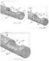
- FIGs. 2A through 2Hillustrate various embodiments of openings 27 in the cannula 20 or a tissue resector 10.
- the cannula 20' depicted by FIG. 2Aincludes an opening 27' through its wall 22' and positioned proximal to the distal end 26' of the cannula 20'.
- This configurationretains the tubularity of distal-most portion of the cannula 20', which may hold a distal end of a cutting wire 30 ( FIGs. 1A and 1B ) in place as the cutting wire 30 is rotated within the lumen 24' of the cannula 20'.
- the opening 27'has a width that is about the same as a diameter of the cannula 20', and is at least partially defined by edges 23' that are oriented longitudinally relative to the length of the cannula 20'.
- the opening 27'is elongated, with its length being oriented along the length of the cannula 20'.
- FIG. 2Bdepicts an embodiment of a cannula 20" that includes an opening 27" with a position and a configuration similar to those of the opening 27' of the embodiment of cannula 20' depicted by FIG. 2A .
- the edges 23" that define the periphery of the opening 27"are configured as blades, with sharper edges adjacent to an interior surface 25" of the lumen 24" than the corresponding edges 23' that define the opening 27' of cannula 20'.
- the edges 23" that define the opening 27"may cut into tissue as a cutting wire 30 ( FIGs. 1A and 1B ) rotates within the lumen 24" that extends through the cannula 20".
- FIG. 2CAnother similarly positioned and configured opening 27'" is depicted by FIG. 2C , but with edges 23''' that include teeth 23 T .
- the teeth 23 Tmay be configured to cut into tissue as a cutting wire 30 ( FIGs. 1A and 1B ) rotates within the lumen 24''' that extends through the cannula 20"'.
- the cannula 20"" depicted by FIG. 2Dincludes an opening 27"" with edges 23"" that comprise serrations 23s. Accordingly, each edge 23"" may include a series of short, curved sections that are adjoined at teeth 23 T "".
- tissue resector 10""' illustrated by FIG. 2Eincludes a cannula 20""' with an opening 27""' that is at least partially defined by edges 23""' that are oriented oblique to the length, or longitudinal axis, of the cannula 20""'.
- tissue resector 110is shown with an opening 127 that extends to the distal end 126 of the cannula 120.
- the portion of the distal end 126 that remainsis closed.
- Such a configurationmay be used with a cutting wire 30' that has a cutting loop 37' at its distal end 36', and may at least partially hold the distal end 36' in place as the cutting wire 30' rotates.
- the edges 123 that define the opening 127may have any configuration, including, but not limited to, a substantially square configuration, or any of the configurations shown in and described in reference to FIGs. 2B through 2E .
- tissue resector 110' shown in FIG. 2Gincludes a cannula 120' with an opening 127' similar in configuration to the opening 127 of the embodiment of cannula 120 depicted by FIG. 2E ; however, the entire distal end 126' of the cannula 120' is open.
- the edges 123' that define the opening 127'may have any configuration, including, but not limited to, a substantially square configuration, or any of the configurations shown in and described in reference to FIGs. 2B through 2E .
- the cannula 220includes an open distal end 226, but no opening that extends into any portion of the circumference ( i.e ., the wall 222) of the cannula 220.
- the distal end 36' of a cutting wire 30'which may be configured ( e.g ., with a loop, etc.) to cut or otherwise separate tissues that are drawn into or otherwise come into contact with the distal end 226 of the cannula 220, may protrude distally beyond the distal end 226 of the cannula 220.
- the cannula 320, 320' of a tissue resector 310,310'may include at least one additional opening 328, 328'.
- Such an opening 328, 328'may tailor the manner in which debris is aspirated through the lumen 324, 324' of the cannula 320, 320' ( e.g., by balancing suction, etc.), or it may provide another location ( i.e., in addition to the opening 327, 327' located closer to the distal end 326, 326' of the cannula 320, 320') at which an undesired growth, such as a uterine polyp or fibroid, may be engaged, severed and aspirated by the tissue resector 310, 310'.
- an undesired growthsuch as a uterine polyp or fibroid
- the opening 328is longitudinally aligned with and located proximal to the opening 327, but is smaller than the opening 327.
- FIG. 3Bshows an embodiment in which the openings 327 and 328 are located on different sides, or at different locations around the circumference, of the cannula 320.
- FIGs. 2A through 2Frespectively show embodiments of cannulas with openings that are that are at least partially defined by edges that are linear or substantially linear, and, with the exception of the embodiment depicted by FIG. 2D , are oriented substantially parallel to the lengths of their respective cannulas
- the edges that define the openings through the illustrated cannulas or any other embodiments of cannulasmay be curved, may include curved sections and/or may be oriented at oblique angles to their respective cannulas.
- the cutting wire 30 of a tissue resector 10may comprise a guide wire of a known type and configuration.
- the cutting wire 30may comprise or consist of a solid filament.
- the cutting wire 30may include a coiled filament, which may surround a solid filament.
- the cutting wire 30may include features that facilitate engagement and/or cutting of tissue, such as grooves or teeth that engage tissue or teeth or a sharpened edge that cuts into tissue.
- the cutting wire 30may include proximal features (e.g., helical grooves, teeth, a helical thread, etc.) that facilitate the proximal movement of tissues through the lumen 24 of the cannula 20 of a tissue resector 10, for example, by breaking down tissues and other materials as they move proximally through the lumen 24, by forcing larger pieces proximally through the lumen 24 or by any other suitable mechanism.
- proximal featurese.g., helical grooves, teeth, a helical thread, etc.
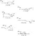
- FIGs. 4A through 4Fdepict a few non-limiting embodiments, not belonging to the invention, of cutting wires 30 that may be used in a tissue resector 10 ( FIGs. 1A and 1B ) according to this disclosure.
- FIG. 4Aan embodiment of a cutting wire 30' is illustrated that is substantially linear along a majority of its length, with a cutting loop 37' at its distal end 36'.
- the cutting loop 37' of the cutting wire 30'may be elongated.
- the length of the cutting loop 37'may be about the same as or exceed the length of an opening 27 ( FIGs. 1A and 1B ) of a cannula 20 ( FIGs. 1A and 1B ) with which the cutting wire 30' is used.
- the width of the cutting loop 37'may be the same as, substantially the same as or less than the inner diameter of the lumen 24 ( FIGs. 1A and 1B ) of a cannula 20 ( FIGs. 1A and 1B ) with which the cutting wire 30' is configured for use.
- both sides of an open cutting loopmay cut into and through tissue.
- a cutting wire 30 with an open cutting loope.g., cutting loop 37', etc.
- tissue twice with each rotationmay be cut tissue twice with each rotation.
- FIG. 4Billustrates an embodiment of cutting wire 30" with a twisted cutting loop 37".
- a twisted cutting loop 37"may have a single twist, imparting it with a configuration that resembles a three-dimensional figure eight.
- a cutting loop 37"may have fewer than one twist or it may include more than one twist.
- the diameter of a twisted loop 37"may be the same as, substantially the same as or less than the inner diameter of the lumen 24 ( FIGs. 1A and 1B ) of a cannula 20 ( FIGs. 1A and 1B ) with which the cutting wire 30" is configured for use.
- a twisted cutting loop 37"may comprise an open loop, or it may comprise a solid, flat element having a helical configuration.
- a cutting wire 30'"may have a cutting feature 37'" formed in its distal end 36"', as illustrated by FIG. 4C .
- the cutting feature 37'"may comprise one or more sharp points, edges, indentations or other features that may enable it to engage and cut tissue.
- FIG. 4DAnother embodiment of cutting wire 130 is shown in FIG. 4D .
- That cutting wire 130includes a cutting element 137 located near its distal end 136.
- the cutting element 137comprises an elongated region of the cutting wire 130 that is offset from a remainder of the length of the cutting wire 130.
- the distance of the offsetmay be the same as, substantially the same as, or less than the radius of a lumen 24 ( FIGs. 1A and 1B ) of a cannula 20 ( FIGs. 1A and 1B ) within which the cutting wire 130 is configured to be positioned.
- the distal end 136 of such a cutting wire 130may be configured to facilitate smooth rotation of the cutting element 137 relative to an opening 27 ( FIGs.
- the distal end 136 of the cutting wire 130is configured complementary to the distal end 26 ( FIGs. 1A and 1B ) of the cannula 20.
- FIG. 4Eillustrates an embodiment of cutting wire 230 with a centering feature 239 along at least a portion of its length, at a location proximal to a cutting element (not shown) of the cutting wire 230.
- the illustrated embodiment of centering feature 239, or any equivalently configured centering feature 239may align an axis of rotation (not shown) of the cutting feature (not shown) with a longitudinal axis through the center of the lumen 24 ( FIGs. 1A and 1B ) of a cannula 20 ( FIGs. 1A and 1B ) with which the cutting wire 230 is to be used.
- Such a configurationmay optimize the stability with which the cutting wire 230 rotates, providing for smooth rotation of the cutting wire 230 within the lumen 24 of the cannula 20.
- FIG. 4FAnother embodiment of cutting wire 330 is shown in FIG. 4F .
- That cutting wire 330includes augers 339 along at least a portion of its length.
- the augers 339may be configured and oriented to facilitate the flow of excised tissue proximally through the lumen 24 ( FIGs. 1A and 1B ) of a cannula 20 ( FIGs. 1A and 1B ) with which the cutting wire 330 is used.
- at least some of the augers 339may be configured and/or oriented to break the excised tissue into smaller pieces, further facilitating the rate at which they may flow proximally through the lumen 24 of the cannula 20.
- the augers 339may have helical configurations, which may comprise one or more Archimedes screws positioned along the length of the cutting wire 330.
- FIG. 4Gillustrates an embodiment of cutting wire 430 of the invention that includes a solid, elongated element 431 with a flattened distal end 432 and a cutter 435 secured to the flattened distal end 432.
- the cutter 435may comprise a cylindrical element with an open proximal end 436, into which the flattened distal end 432 of the elongated element 431 extends.
- a distal end 437 of the cutter 435may also be open ( e.g., to enable samples and/or debris to be aspirated therein, etc.).
- the cutter 435may also include one or more features that may cooperate with an opening 27 through a cannula 20 ( see, e.g., FIG. 1B ).
- a slot 438extends along a portion of a length of the cutter 435, with opposed edges 439 of the slot 438 being configured to cut into body tissue or other materials as the cutting wire 430 is rotated within a lumen 21 of a cannula 20.
- the edges 439may comprise blades, teeth or serrations or other features that enable them to cut readily into and through body tissue or other materials.
- the cutting wire 30 of a tissue resector 10may be of any suitable size (e.g., have an outer diameter) that will cut tissue in the desired manner while enabling the tissue to be aspirated through the lumen 24 of the cannula 20 at an acceptable rate (e.g., at a rate that will minimize the duration of a tissue resection procedure and, thus, the pain suffered by a patient, etc.).
- acceptable rates of aspirationmay be achieved with a tissue resector 10 that has a lumen 24 with an open cross-sectional area (i.e., the cross-sectional area of the lumen 24 minus the cross-sectional area of the cutting wire 30) that is at least 50% of the cross-sectional area of the cannula 20.
- the use of smaller cutting wires 30would provide an even larger percentage of open area (e.g., at least 60%, at least 65%, at least 70%, etc.) and enable even greater rates of aspiration.
- a tissue resector 10may be operated under manual power (i.e., by hand) with a rooter 50, such as that described by U.S. Patent Application Publication No. US 2012/0239008 of Fojtik. Together, the tissue resector 10 and the rooter 50 may provide a tissue resector system 1.
- a rooter 50may easily be used to rotate a cutting wire 30 at about 500 revolutions per minute (rpm), and can generate up to about 3,000 rpm, which may result in about 1,000 cuts per minute and 6,000 cuts per minute, respectively.
- the rooter 50 of a tissue resector system 1may enable rotation of a cutting wire 30 of the tissue resector 10 as the cannula 20 of the tissue resector 10 is held substantially stationary. As the rooter 50 is manually operated, it may spin the cutting wire 30 in a repetitious back-and-forth (i.e ., clockwise and counterclockwise) manner, which may provide for two sets of cutting wire 30 rotations with each pull (or push) on an actuator of the rooter 50.
- a repetitious back-and-forthi.e ., clockwise and counterclockwise
- cutting wire 30'( FIG. 4A ) having an open cutting loop 37' ( FIG. 4A ) is used in the tissue resector system 1, since the cutting loop 37' cuts tissue twice with each rotation of the cutting wire 30', manual operation of the rooter 50 and, thus, hand-operated rotation of the cutting wire 30' may efficiently cut tissue and, thus remove the same from an individual's body.
- a rooter 50that is configured for hand-powered operation may also be used with the limited use (e.g. disposable, etc.) portion 70 of a conventional morcellator, providing another embodiment of tissue resector system 1'.
- adapter 60includes a series of elements that translate the action generated by the rooter 50 to an action that rotates the inner cannula, or blade 72, of a conventional morcellator. More specifically, the adapter 60 may include elements 61 and 62 that are respectively configured to engage a rotatable element of the rooter 50 and a proximal end 73 of the blade 72. Element 62, which is configured to engage the proximal end 73 of the blade 72, may be configured to rotate the blade 72 about an eccentric axis ( e.g. , an axis that enables the blade 72 to move rotational over an inner circumference of a lumen 74 of an outer cannula 76, etc.).
- an eccentric axise.g. , an axis that enables the blade 72 to move rotational over an inner circumference of a lumen 74 of an outer cannula 76, etc.
- the adapter 60may include one or more stationary elements 63 and/or a distal end cap 66 that may be configured to hold the outer cannula 76 that surrounds the blade 72 stationary, even while the blade 72 is rotated within a lumen 74 of the outer cannula 76.
- the adapter 60may include seals 67, 68, which enable movement of the blade 72 within the lumen 74 of the outer cannula 76. while simultaneously enabling the aspiration of body tissues, fluids or the like through the lumen 74 of the outer cannula 76, through the housing 65 of the adapter 60 and through an aspiration port 64 that communicates with an interior of the housing 65 of the adapter 60.
- the seals 67, 68enable a suction (i.e., a vacuum) to be applied to the aspiration port 64 and communicated through the housing 65 of the adapter to the lumen 74 of the outer cannula 76 to drawn tissue, fluid or other materials proximally therethrough.
- a tissue resector 10may also be used with a power-drive instrument 90 of a conventional morcellator when coupled to the power-drive instrument 90 with an appropriately configured adapter 80.
- the adapter 80may be configured to translate rotating action by the power-drive instrument 90 to the cutting wire 30 ( FIGs. 1A and 1B ) of the tissue resector 10 and convert a system that aspirates through the power-drive instrument 90 for communication with the lumen 24 ( FIGs. 1A and 1B ) that extends through the outer cannula 20 ( FIGs. 1A and 1B ) of the tissue resector 10.
Landscapes
- Health & Medical Sciences (AREA)
- Surgery (AREA)
- Life Sciences & Earth Sciences (AREA)
- Biomedical Technology (AREA)
- Nuclear Medicine, Radiotherapy & Molecular Imaging (AREA)
- Engineering & Computer Science (AREA)
- Heart & Thoracic Surgery (AREA)
- Medical Informatics (AREA)
- Molecular Biology (AREA)
- Animal Behavior & Ethology (AREA)
- General Health & Medical Sciences (AREA)
- Public Health (AREA)
- Veterinary Medicine (AREA)
- Orthopedic Medicine & Surgery (AREA)
- Surgical Instruments (AREA)
Description
- A claim to the benefit of the April 28, 2014 filing date of
U.S. Provisional Patent Application No. 61/985,283 - This disclosure relates generally to tissue resectors and, more specifically, to tissue resectors that efficiently aspirate excised tissue. In particular, tissue resectors that employ wires to remove undesired tissue, such as polyps and fibroids, are disclosed. Systems and exemplary methods for tissue resecting are also disclosed.
- Morcellation is a process by which undesirable growths, such as benign tumors, polyps and fibroids, are removed from within a subject's body. Physicians have used morcellation in gynecological surgeries. For example, high powered electric morcellators have been used to laparoscopically extract the uterus (i.e., hysterectomy). Specifically, an electric morcellator grinds the entire uterus, including any undiagnosed sarcomas. While the risk is relatively small that these cancerous tissues remain within a woman's body, there is a significant likelihood that any cancerous cells that remain within the body may spread.
- In less invasive procedures, smaller morcellators have been used in conjunction with hysteroscopes to remove relatively small uterine polyps (e.g., polyps with diameters of about 3 cm or less, etc.) and fibroids (which typically have diameters of about 1 cm to about 2 cm). Some hysteroscopes are configured to inflate the uterine cavity with fluid or air. With the uterine cavity inflated, a light source of the hysteroscope may illuminate the interior surfaces of the uterus, and a camera of the hysterscope and a display associated with the camera of the hysteroscope may enable a physician to visualize features, such as polyps and fibroids, on interior surfaces of the uterus. While the physician is looking at the interior surface of the uterine wall, he or she may operate a morcellator in conjunction with the hysteroscope to remove any polyps or fibroids that appear on the display. Debris from the morcellation process may be aspirated through the morcellator, and collected for pathology.
- The morcellators that are currently used to remove uterine polyps and fibroids are power-driven devices. A typical morcellator includes an outer cannula with an opening located near its distal end and formed in a portion of the circumference of the outer cannula. An inner cannula is positioned within a lumen of the outer cannula, and includes a distal end that defines and blade that communicates with the opening near the distal end of the outer cannula. Depending upon the configurations of the opening and the blade, the inner cannula may rotate within the lumen of the outer cannula, or the inner cannula may move longitudinally back and forth within the outer cannula. In any configuration, a polyp or fibroid may be drawn into the opening in the outer cannula, and then cut with the blade of the inner cannula. Once the polyp or fibroid, or a portion thereof, has been cut from the inner surface of the uterus, it may be drawn, by way of a vacuum, through a lumen in the inner cannula.
- One example of an existing morcellator is the TRUCLEAR® morcellator offered by Smith & Nephew. That morcellator includes an outer cannula that has an outer diameter of 0.114 inch (2.9 mm) (i.e., a cross- sectional area of 0.0102 in2 or 6.6 mm2) and an inner cannula with an inner diameter of about 0.070 inch (1.8 mm) (i.e., a cross-sectional area of 0.00385 in2 or 2.5 mm2). Thus, the available, open cross-sectional area through that device only comprises 37.7% of the overall cross-sectional area occupied by the cannula of that device.
- Hysteroscopy and morcellation can be painful. The relatively small inner diameters of the inner cannulas of existing morcellators limit the rate at which excised tissues (e.g., polyps, fibroids, etc.) may be collected, which unfortunately and undesirably prolongs the morcellation procedure and the pain caused by that procedure. Document
US 2007/0265633 A1 relates to a device directed to rapid surgical removal of the nucleus pulposus from the spin intervertebral space. This document does not disclose an elongated element with a flattened distal end and a cutting feature secured to the flattened distal end that cooperates with the opening through the cannula, wherein the cutting feature includes a cylindrical element with an open proximal end into which the flattened distal end of the elongated element extends, and wherein a slot extends along a portion of a length of the cylindrical element, the cutting wire enables tissue to be aspirated through the lumen of the cannula, and the cutting wire is configured to rotate eccentrically within the lumen of the cannula. - The present invention relates to a tissue resector as defined in appended
claim 1. Preferred embodiments are defined in appended claims. A tissue resector according to this disclosure includes a cannula and a cutting wire. The cannula has a lumen within which the cutting wire is positioned. The cannula includes an opening located at or adjacent to its distal end. The opening may be configured to receive uterine polyps and fibroids. A cutting feature at or near a distal end of the cutting wire cooperates with the opening of the cannula in such a way that the cutting feature will cut, slice, shear, chew or tear tissue that is introduced (e.g., by suction, etc.) into the opening. For the sake of simplicity, the acts of cutting, slicing, shearing, chewing, tearing and similar actions are individually and collectively referred to herein as "cutting." The use of a cutting wire within a single cannula provides for a relatively large cross-sectional area through which tissue may be aspirated through the cannula. - In various embodiments, of the entire cross-sectional area occupied by the cannula, at least 50% may be available for aspiration. In some embodiments (e.g., embodiments where smaller cutting wires are used, etc.), the open area may comprise 60% or even 70% of the entire cross-sectional area occupied by the cannula.
- In another aspect of this disclosure, a tissue resector according to this disclosure may be part of a tissue resector system. In some embodiments, the tissue resector may be used with a rooter that operates under manual power, such as that disclosed by U.S. Patent Application Publication No.
US 2012/0239008 of Fojtik. Such a rooter is also referred to herein as a "hand-powered rooter" and as a "manual spinning instrument." In other embodiments, the tissue resector may be used with a power-driven instrument, such as those used to drive the inner cannulas of existing morcellators, and an appropriate adapter, which translates actions of the power-driven instrument to the features of a tissue resector with a single cannula and a cutting wire. - Another embodiment of tissue resector system not belonging to the invention includes an existing tissue resector blade (with an outer cannula and an inner cannula on which a blade is defined), a hand-operated rooter and an adapter for converting actions of the rooter to the features of existing tissue resector blade.
- As an example of use, a tissue resector or tissue resector system according to this disclosure may be used to remove undesired growths from a woman's uterus, including, without limitation, polyps, fibroids and other undesirable growths. While viewing such a growth, it may be drawn into the opening of a cannula under suction (i.e., a vacuum) applied to the lumen of the cannula. With the tissue in the opening, the cutting wire may be rotated, and its cutting feature may cut tissue from the growth. This process may continue until the growth and immediately adjacent tissues have been removed. The tissues, which are aspirated, may then be collected and evaluated by a pathologist.
- Other aspects, as well as features and advantages of various aspects, of the disclosed subject matter will become apparent to those of ordinary skill in the art through consideration of the ensuing description, the accompanying drawings and the appended claims.
- In the drawings:
FIGs. 1A and 1B depict an embodiment of a tissue resector that includes a cannula and a cutting wire within a lumen of the cannula;FIGs. 2A through 2H depict various embodiments of distal ends of and openings of the cannulas of various embodiments of tissue resectors that incorporate the features shown inFIGs. 1A and 1B ;FIGs. 3A and 3B illustrate some embodiments of cannulas that include two or more openings;FIGs. 4A through 4G show some embodiments, not all belonging to the invention, of cutting wires that may be used with a tissue resector, such as that depicted byFIGs. 1A and 1B ;FIGs. 5A through 5C illustrate an embodiment of a tissue resector system that includes a tissue resector of the type shown inFIGs. 1A and 1B , as well as a hand-powered rooter, withFIG. 5A illustrating the tissue resector system in an assembled state,FIG. 5B providing an exploded view of the elements of the hand-powered rooter and the tissue resector andFIG. 5C providing a cross-sectional representation of the tissue resector system;FIGs. 6A and6B show an embodiment, not belonging to the invention, of an adapter for enabling use a hand-powered rooter with an existing morcellator, as well as an embodiment, not belonging to the invention, of a tissue resector system that includes the hand-powered rooter, the adapter and the morcellator; andFIG. 7 depicts an embodiment, not belonging to the invention, of an adapter for enabling use of a tissue resector of the type illustrated byFIGs. 1A and 1B with a power-drive instrument of a conventional morcellation device, as well as an embodiment, not belonging to the invention, of a tissue resector system including the power-drive instrument, the adapter and the tissue resector.- As shown in
FIGs. 1A and 1B , atissue resector 10 according to this disclosure includes acannula 20 and acutting wire 30. Thecannula 20 is an elongated tubular element with awall 22 that defines alumen 24 along its length. In the illustrated embodiment, thecannula 20 is substantially straight; however, atissue resector 10 according to this disclosure may include acurved cannula 20 or even abent cannula 20. - The
cannula 20 of atissue resector 10 may have any of a variety of different dimensions. Without limitation, acannula 20 may have an outer diameter of about 5 French (i.e., 0.066 inch; 1.67 mm), about 7 French (i.e., 0.092 inch; 2.33 mm) or about 9 French (i.e., 0.118 inch; 3 mm), which may correspond to the size of a hysteroscope (e.g., to the size of an access lumen through the hysteroscope, etc.) with which thetissue resector 10 is to be used. In a specific embodiment, thecannula 20 may comprise a hypotube with an outer diameter of 0.115 inch (2.9 mm) and an inner diameter of 0.095 inch (2.4 mm). - At or near its
distal end 26, thecannula 20 includes anopening 27. Theopening 27 is configured to receive undesirable growths, such as uterine polyps and fibroids. In some embodiments, theedges 23 of theouter wall 22 that define theopening 27 may be configured to facilitate separation of unwanted tissue from adjacent (e.g., healthy) tissue. FIGs. 2A through 2H illustrate various embodiments ofopenings 27 in thecannula 20 or atissue resector 10.- The cannula 20' depicted by
FIG. 2A includes an opening 27' through its wall 22' and positioned proximal to the distal end 26' of the cannula 20'. This configuration retains the tubularity of distal-most portion of the cannula 20', which may hold a distal end of a cutting wire 30 (FIGs. 1A and 1B ) in place as thecutting wire 30 is rotated within the lumen 24' of the cannula 20'. The opening 27' has a width that is about the same as a diameter of the cannula 20', and is at least partially defined by edges 23' that are oriented longitudinally relative to the length of the cannula 20'. The opening 27' is elongated, with its length being oriented along the length of the cannula 20'. FIG. 2B depicts an embodiment of acannula 20" that includes anopening 27" with a position and a configuration similar to those of the opening 27' of the embodiment of cannula 20' depicted byFIG. 2A . However, theedges 23" that define the periphery of theopening 27" are configured as blades, with sharper edges adjacent to aninterior surface 25" of thelumen 24" than the corresponding edges 23' that define the opening 27' of cannula 20'. Thus, theedges 23" that define theopening 27" may cut into tissue as a cutting
wire 30 (FIGs. 1A and 1B ) rotates within thelumen 24" that extends through thecannula 20".- Another similarly positioned and configured opening 27'" is depicted by
FIG. 2C , but with edges 23''' that includeteeth 23T. Theteeth 23T may be configured to cut into tissue as a cutting wire 30 (FIGs. 1A and 1B ) rotates within the lumen 24''' that extends through thecannula 20"'. - The
cannula 20"" depicted byFIG. 2D includes anopening 27"" withedges 23"" that compriseserrations 23s. Accordingly, eachedge 23"" may include a series of short, curved sections that are adjoined atteeth 23T"". - The embodiment of
tissue resector 10""' illustrated byFIG. 2E includes acannula 20""' with anopening 27""' that is at least partially defined byedges 23""' that are oriented oblique to the length, or longitudinal axis, of thecannula 20""'. - In
FIG. 2F , an embodiment oftissue resector 110 is shown with anopening 127 that extends to thedistal end 126 of thecannula 120. In that embodiment, the portion of thedistal end 126 that remains is closed. Such a configuration may be used with a cutting wire 30' that has a cutting loop 37' at its distal end 36', and may at least partially hold the distal end 36' in place as the cutting wire 30' rotates. Theedges 123 that define theopening 127 may have any configuration, including, but not limited to, a substantially square configuration, or any of the configurations shown in and described in reference toFIGs. 2B through 2E . - The embodiment of tissue resector 110' shown in
FIG. 2G includes a cannula 120' with an opening 127' similar in configuration to theopening 127 of the embodiment ofcannula 120 depicted byFIG. 2E ; however, the entire distal end 126' of the cannula 120' is open. The edges 123' that define the opening 127' may have any configuration, including, but not limited to, a substantially square configuration, or any of the configurations shown in and described in reference toFIGs. 2B through 2E . - In the embodiment of
tissue resector 210 depicted byFIG. 2H , thecannula 220 includes an opendistal end 226, but no opening that extends into any portion of the circumference (i.e., the wall 222) of thecannula 220. The distal end 36' of a cutting wire 30', which may be configured (e.g., with a loop, etc.) to cut or otherwise separate tissues that are drawn into or otherwise come into contact with thedistal end 226 of thecannula 220, may protrude distally beyond thedistal end 226 of thecannula 220. - In some embodiments, such as those depicted by
FIGs. 3A and 3B , thecannula 320, 320' of a tissue resector 310,310' may include at least oneadditional opening 328, 328'. Such anopening 328, 328' may tailor the manner in which debris is aspirated through thelumen 324, 324' of thecannula 320, 320' (e.g., by balancing suction, etc.), or it may provide another location (i.e., in addition to theopening 327, 327' located closer to thedistal end 326, 326' of thecannula 320, 320') at which an undesired growth, such as a uterine polyp or fibroid, may be engaged, severed and aspirated by thetissue resector 310, 310'. In the embodiment depicted byFIG. 3A , theopening 328 is longitudinally aligned with and located proximal to theopening 327, but is smaller than theopening 327.FIG. 3B shows an embodiment in which theopenings cannula 320. - While
FIGs. 2A through 2F respectively show embodiments of cannulas with openings that are that are at least partially defined by edges that are linear or substantially linear, and, with the exception of the embodiment depicted byFIG. 2D , are oriented substantially parallel to the lengths of their respective cannulas, the edges that define the openings through the illustrated cannulas or any other embodiments of cannulas may be curved, may include curved sections and/or may be oriented at oblique angles to their respective cannulas. - With returned reference to
FIGs. 1A and 1B , thecutting wire 30 of atissue resector 10 may comprise a guide wire of a known type and configuration. Without limitation, thecutting wire 30 may comprise or consist of a solid filament. Alternatively, thecutting wire 30 may include a coiled filament, which may surround a solid filament. As another alternative, thecutting wire 30 may include features that facilitate engagement and/or cutting of tissue, such as grooves or teeth that engage tissue or teeth or a sharpened edge that cuts into tissue. In still another alternative, thecutting wire 30 may include proximal features (e.g., helical grooves, teeth, a helical thread, etc.) that facilitate the proximal movement of tissues through thelumen 24 of thecannula 20 of atissue resector 10, for example, by breaking down tissues and other materials as they move proximally through thelumen 24, by forcing larger pieces proximally through thelumen 24 or by any other suitable mechanism. FIGs. 4A through 4F depict a few non-limiting embodiments, not belonging to the invention, of cuttingwires 30 that may be used in a tissue resector 10 (FIGs. 1A and 1B ) according to this disclosure.- In
FIG. 4A , an embodiment of a cutting wire 30' is illustrated that is substantially linear along a majority of its length, with a cutting loop 37' at its distal end 36'. The cutting loop 37' of the cutting wire 30' may be elongated. The length of the cutting loop 37' may be about the same as or exceed the length of an opening 27 (FIGs. 1A and 1B ) of a cannula 20 (FIGs. 1A and 1B ) with which the cutting wire 30' is used. The width of the cutting loop 37' may be the same as, substantially the same as or less than the inner diameter of the lumen 24 (FIGs. 1A and 1B ) of a cannula 20 (FIGs. 1A and 1B ) with which the cutting wire 30' is configured for use. - In use, both sides of an open cutting loop, such as the embodiment of cutting loop 37' depicted by
FIG. 4A , may cut into and through tissue. Thus, acutting wire 30 with an open cutting loop (e.g., cutting loop 37', etc.) may cut tissue twice with each rotation. FIG. 4B illustrates an embodiment of cuttingwire 30" with atwisted cutting loop 37". As shown, atwisted cutting loop 37" may have a single twist, imparting it with a configuration that resembles a three-dimensional figure eight. Of course, a cuttingloop 37" may have fewer than one twist or it may include more than one twist. The diameter of a twistedloop 37" may be the same as, substantially the same as or less than the inner diameter of the lumen 24 (FIGs. 1A and 1B ) of a cannula 20 (FIGs. 1A and 1B ) with which thecutting wire 30" is configured for use. Atwisted cutting loop 37" may comprise an open loop, or it may comprise a solid, flat element having a helical configuration.- As another option, a cutting wire 30'" may have a cutting feature 37'" formed in its
distal end 36"', as illustrated byFIG. 4C . The cutting feature 37'" may comprise one or more sharp points, edges, indentations or other features that may enable it to engage and cut tissue. - Another embodiment of cutting
wire 130 is shown inFIG. 4D . Thatcutting wire 130 includes a cutting element 137 located near its distal end 136. The cutting element 137 comprises an elongated region of thecutting wire 130 that is offset from a remainder of the length of thecutting wire 130. The distance of the offset may be the same as, substantially the same as, or less than the radius of a lumen 24 (FIGs. 1A and 1B ) of a cannula 20 (FIGs. 1A and 1B ) within which thecutting wire 130 is configured to be positioned. The distal end 136 of such acutting wire 130 may be configured to facilitate smooth rotation of the cutting element 137 relative to an opening 27 (FIGs. 1A and 1B ) through awall 22 of thecannula 20 with which thecutting wire 130 is configured to be used. In the depicted embodiment, the distal end 136 of thecutting wire 130 is configured complementary to the distal end 26 (FIGs. 1A and 1B ) of thecannula 20. FIG. 4E illustrates an embodiment of cuttingwire 230 with a centeringfeature 239 along at least a portion of its length, at a location proximal to a cutting element (not shown) of thecutting wire 230. The illustrated embodiment of centeringfeature 239, or any equivalently configured centeringfeature 239, may align an axis of rotation (not shown) of the cutting feature (not shown) with a longitudinal axis through the center of the lumen 24 (FIGs. 1A and 1B ) of a cannula 20 (FIGs. 1A and 1B ) with which thecutting wire 230 is to be used. Such a configuration may optimize the stability with which thecutting wire 230 rotates, providing for smooth rotation of thecutting wire 230 within thelumen 24 of thecannula 20.- Another embodiment of cutting
wire 330 is shown inFIG. 4F . Thatcutting wire 330 includes augers 339 along at least a portion of its length. The augers 339 may be configured and oriented to facilitate the flow of excised tissue proximally through the lumen 24 (FIGs. 1A and 1B ) of a cannula 20 (FIGs. 1A and 1B ) with which thecutting wire 330 is used. In some embodiments, at least some of the augers 339 may be configured and/or oriented to break the excised tissue into smaller pieces, further facilitating the rate at which they may flow proximally through thelumen 24 of thecannula 20. In some embodiments may comprise discrete elements. In other embodiments, the augers 339 may have helical configurations, which may comprise one or more Archimedes screws positioned along the length of thecutting wire 330. FIG. 4G illustrates an embodiment of cuttingwire 430 of the invention that includes a solid,elongated element 431 with a flattened distal end 432 and a cutter 435 secured to the flattened distal end 432. The cutter 435 may comprise a cylindrical element with an openproximal end 436, into which the flattened distal end 432 of theelongated element 431 extends. A distal end 437 of the cutter 435 may also be open (e.g., to enable samples and/or debris to be aspirated therein, etc.). The cutter 435 may also include one or more features that may cooperate with anopening 27 through a cannula 20 (see, e.g.,FIG. 1B ). In the illustrated embodiment, aslot 438 extends along a portion of a length of the cutter 435, withopposed edges 439 of theslot 438 being configured to cut into body tissue or other materials as thecutting wire 430 is rotated within a lumen 21 of acannula 20. In some embodiments, theedges 439 may comprise blades, teeth or serrations or other features that enable them to cut readily into and through body tissue or other materials.- Returning reference again to
FIGs. 1A and 1B , thecutting wire 30 of atissue resector 10 may be of any suitable size (e.g., have an outer diameter) that will cut tissue in the desired manner while enabling the tissue to be aspirated through thelumen 24 of thecannula 20 at an acceptable rate (e.g., at a rate that will minimize the duration of a tissue resection procedure and, thus, the pain suffered by a patient, etc.). As an example, acceptable rates of aspiration may be achieved with atissue resector 10 that has alumen 24 with an open cross-sectional area (i.e., the cross-sectional area of thelumen 24 minus the cross-sectional area of the cutting wire 30) that is at least 50% of the cross-sectional area of thecannula 20. In a specific embodiment, acannula 20 with an outer diameter of 0.115 inch (2.9 mm) (i.e., a cross-sectional area of 0.0104 in2 or 6.7 mm2) and an inner diameter of 0.095 inch (2.4 mm) (i.e., a cross-sectional area of 0.00709 in2 or 4.6mm2), when used with a 0.040 inch (1 mm) (i.e., 0.00126 in2 or 0.8 mm2 in cross-sectional area) cuttingwire 30, will have an open cross-sectional area of 0.00583 in2 or 3.8 mm2, which accounts for 56.1% of the entire cross-sectional area occupied by thecannula 20. Of course, the use ofsmaller cutting wires 30 would provide an even larger percentage of open area (e.g., at least 60%, at least 65%, at least 70%, etc.) and enable even greater rates of aspiration. - As illustrated by
FIGs. 5A through 5C , atissue resector 10 according to this disclosure may be operated under manual power (i.e., by hand) with arooter 50, such as that described by U.S. Patent Application Publication No.US 2012/0239008 of Fojtik. Together, thetissue resector 10 and therooter 50 may provide atissue resector system 1. Such arooter 50 may easily be used to rotate acutting wire 30 at about 500 revolutions per minute (rpm), and can generate up to about 3,000 rpm, which may result in about 1,000 cuts per minute and 6,000 cuts per minute, respectively. - The
rooter 50 of atissue resector system 1 may enable rotation of acutting wire 30 of thetissue resector 10 as thecannula 20 of thetissue resector 10 is held substantially stationary. As therooter 50 is manually operated, it may spin thecutting wire 30 in a repetitious back-and-forth (i.e., clockwise and counterclockwise) manner, which may provide for two sets of cuttingwire 30 rotations with each pull (or push) on an actuator of therooter 50. - When an embodiment, not belonging to the invention, of cutting wire 30' (
FIG. 4A ) having an open cutting loop 37' (FIG. 4A ) is used in thetissue resector system 1, since the cutting loop 37' cuts tissue twice with each rotation of the cutting wire 30', manual operation of therooter 50 and, thus, hand-operated rotation of the cutting wire 30' may efficiently cut tissue and, thus remove the same from an individual's body. - Turning now to
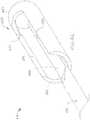
FIGs. 6A and6B , with aproper adapter 60, arooter 50 that is configured for hand-powered operation may also be used with the limited use (e.g. disposable, etc.)portion 70 of a conventional morcellator, providing another embodiment of tissue resector system 1'. - The depicted embodiment, not belonging to the invention, of
adapter 60 includes a series of elements that translate the action generated by therooter 50 to an action that rotates the inner cannula, orblade 72, of a conventional morcellator. More specifically, theadapter 60 may include elements 61 and 62 that are respectively configured to engage a rotatable element of therooter 50 and aproximal end 73 of theblade 72. Element 62, which is configured to engage theproximal end 73 of theblade 72, may be configured to rotate theblade 72 about an eccentric axis (e.g., an axis that enables theblade 72 to move rotational over an inner circumference of alumen 74 of anouter cannula 76, etc.). - In addition, the
adapter 60 may include one or more stationary elements 63 and/or a distal end cap 66 that may be configured to hold theouter cannula 76 that surrounds theblade 72 stationary, even while theblade 72 is rotated within alumen 74 of theouter cannula 76. - In addition, the
adapter 60 may include seals 67, 68, which enable movement of theblade 72 within thelumen 74 of theouter cannula 76. while simultaneously enabling the aspiration of body tissues, fluids or the like through thelumen 74 of theouter cannula 76, through thehousing 65 of theadapter 60 and through anaspiration port 64 that communicates with an interior of thehousing 65 of theadapter 60. Thus, the seals 67, 68 enable a suction (i.e., a vacuum) to be applied to theaspiration port 64 and communicated through thehousing 65 of the adapter to thelumen 74 of theouter cannula 76 to drawn tissue, fluid or other materials proximally therethrough. - As depicted by
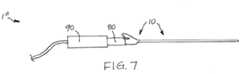
FIG. 7 , in another embodiment, not belonging to the invention, oftissue resector system 1", atissue resector 10 may also be used with a power-drive instrument 90 of a conventional morcellator when coupled to the power-drive instrument 90 with an appropriately configuredadapter 80. Theadapter 80 may be configured to translate rotating action by the power-drive instrument 90 to the cutting wire 30 (FIGs. 1A and 1B ) of thetissue resector 10 and convert a system that aspirates through the power-drive instrument 90 for communication with the lumen 24 (FIGs. 1A and 1B ) that extends through the outer cannula 20 (FIGs. 1A and 1B ) of thetissue resector 10. - Although the foregoing disclosure provides many specifics, these should not be construed as limiting the scope of any of the ensuing claims. Other embodiments may be devised which do not depart from the scopes of the claims. Features from different embodiments may be employed in combination. The scope of each claim is, therefore, indicated and limited only by its plain language.
Claims (12)
- A tissue resector (10), comprising:a cannula (20) including:a wall (22);a lumen (24) defined through the wall (22) and extending along a length of the cannula (20);a distal end (26); andan opening (27) at or adjacent to the distal end (26) and establishing communication between an exterior of the wall (22) and the lumen (24); anda cutting wire (430) within the lumen (24), the cutting wire (430) including:an elongated element (431) with a flattened distal end (432); anda cutting feature secured to the flattened distal end (432) that is configured to cooperate with the opening (27) through the cannula (20);wherein the cutting feature includes a cylindrical element with an open proximal end (436) into which the flattened distal end (432) of the elongated element (431) extends;wherein a slot (438) extends along a portion of a length of the cylindrical element;wherein the cutting wire (430) is sized to enable tissue to be aspirated through the lumen (24) of the cannula (20) while cutting tissue;wherein the cutting wire (430) is configured to rotate eccentrically within the lumen (24) of the cannula (20).
- The tissue resector (10) of claim 1, wherein an open cross-sectional area including a cross-sectional area of the lumen (24) less a cross-sectional area of the cutting wire (430) comprises at least 50% of the cross-sectional area of the cannula (20).
- The tissue resector (10) of claim 2, wherein an outer diameter of the cannula (20) is about 2.9 mm and a diameter of the lumen (24) is about 2.4 mm.
- The tissue resector (10) of claim 3, wherein the cutting wire (430) has an outer diameter of about 1 mm or less.
- The tissue resector (10) of any of claims 1-4, wherein the opening (27) of the cannula (20) is defined through a circumference of the cannula (20).
- The tissue resector (10) of claim 5, wherein the opening (27) of the cannula (20) is spaced proximally from the distal end (26) of the cannula (20).
- The tissue resector (10) of claim 5, wherein the opening (27) of the cannula (20) extends to the distal end (26) of the cannula (20).
- The tissue resector (10) of any of claims 1-4, wherein the opening (27) of the cannula (20) is defined through the distal end (26) of the cannula (20).
- The tissue resector (10) of any of claims 1-8, wherein the opening (27) of the cannula (20) includes at least one edge configured to cut into tissue.
- The tissue resector (10) of any of claims 1-9, wherein the cutting feature of the cutting wire (430) includes at least one edge (439) configured to cut into tissue.
- The tissue resector (10) of any of claims 1-10, wherein the cannula (20) further includes:
at least one secondary opening through the wall (22) of the cannula (20) and located proximal to the opening (27). - A tissue resector system, comprising:a tissue resector (10) according to any of claims 1-11; anda hand-powered rooter for rotating the cutting wire (430) of the tissue resector (10).
Priority Applications (1)
| Application Number | Priority Date | Filing Date | Title |
|---|---|---|---|
| EP19207289.0AEP3653147B1 (en) | 2014-04-28 | 2015-04-28 | Tissue resectors with cutting wires and hand-operated tissue resector systems |
Applications Claiming Priority (2)
| Application Number | Priority Date | Filing Date | Title |
|---|---|---|---|
| US201461985283P | 2014-04-28 | 2014-04-28 | |
| PCT/US2015/028084WO2015168179A1 (en) | 2014-04-28 | 2015-04-28 | Tissue resectors with cutting wires, hand-operated tissue resector systems and associated methods |
Related Child Applications (1)
| Application Number | Title | Priority Date | Filing Date |
|---|---|---|---|
| EP19207289.0ADivisionEP3653147B1 (en) | 2014-04-28 | 2015-04-28 | Tissue resectors with cutting wires and hand-operated tissue resector systems |
Publications (3)
| Publication Number | Publication Date |
|---|---|
| EP3136998A1 EP3136998A1 (en) | 2017-03-08 |
| EP3136998A4 EP3136998A4 (en) | 2017-12-06 |
| EP3136998B1true EP3136998B1 (en) | 2019-11-27 |
Family
ID=54333666
Family Applications (2)
| Application Number | Title | Priority Date | Filing Date |
|---|---|---|---|
| EP15785861.4AActiveEP3136998B1 (en) | 2014-04-28 | 2015-04-28 | Tissue resectors with cutting wires and hand-operated tissue resector systems |
| EP19207289.0AActiveEP3653147B1 (en) | 2014-04-28 | 2015-04-28 | Tissue resectors with cutting wires and hand-operated tissue resector systems |
Family Applications After (1)
| Application Number | Title | Priority Date | Filing Date |
|---|---|---|---|
| EP19207289.0AActiveEP3653147B1 (en) | 2014-04-28 | 2015-04-28 | Tissue resectors with cutting wires and hand-operated tissue resector systems |
Country Status (6)
| Country | Link |
|---|---|
| US (1) | US10376278B2 (en) |
| EP (2) | EP3136998B1 (en) |
| CN (1) | CN106456207B (en) |
| AU (1) | AU2015253317B2 (en) |
| CA (1) | CA2949968C (en) |
| WO (1) | WO2015168179A1 (en) |
Families Citing this family (30)
| Publication number | Priority date | Publication date | Assignee | Title |
|---|---|---|---|---|
| EP3689274A1 (en) | 2007-02-05 | 2020-08-05 | Boston Scientific Limited | Thrombectomy system |
| US9510854B2 (en) | 2008-10-13 | 2016-12-06 | Boston Scientific Scimed, Inc. | Thrombectomy catheter with control box having pressure/vacuum valve for synchronous aspiration and fluid irrigation |
| JP6317751B2 (en) | 2012-11-08 | 2018-04-25 | ボストン サイエンティフィック サイムド,インコーポレイテッドBoston Scientific Scimed,Inc. | System for performing medical procedures |
| US10667836B2 (en)* | 2014-04-28 | 2020-06-02 | Boston Scientific Scimed, Inc. | Tissue resectors, hand operated tissue resecting systems, and associated methods |
| US9883877B2 (en) | 2014-05-19 | 2018-02-06 | Walk Vascular, Llc | Systems and methods for removal of blood and thrombotic material |
| US10561440B2 (en)* | 2015-09-03 | 2020-02-18 | Vesatek, Llc | Systems and methods for manipulating medical devices |
| US10470793B2 (en)* | 2015-09-29 | 2019-11-12 | Merit Medical Systems, Inc. | Devices for rotating medical instruments and related systems and methods |
| EP3600089B1 (en)* | 2017-03-20 | 2023-09-06 | Penumbra, Inc. | Apparatus for removal of intracranial hemorrhage |
| WO2019160508A1 (en)* | 2018-02-19 | 2019-08-22 | Singapore Health Services Pte Ltd | Method and apparatus for shearing tissue at a target surgical site |
| US11678905B2 (en) | 2018-07-19 | 2023-06-20 | Walk Vascular, Llc | Systems and methods for removal of blood and thrombotic material |
| US10576248B2 (en)* | 2018-07-23 | 2020-03-03 | Crossbay Medical, Inc. | Apparatus and method for everting catheter for uterine access for biopsy and cytology |
| US11304713B2 (en) | 2018-09-07 | 2022-04-19 | Merit Medical Systems, Inc. | Thrombosis macerating and aspiration devices for blood vessels |
| US20200113619A1 (en)* | 2018-10-11 | 2020-04-16 | Rebound Therapeutics Corporation | Cautery tool for intracranial surgery |
| WO2020160179A1 (en) | 2019-01-31 | 2020-08-06 | Merit Medical Systems, Inc. | Thrombosis macerating devices for blood vessels |
| US11883058B2 (en) | 2019-03-26 | 2024-01-30 | Covidien Lp | Jaw members, end effector assemblies, and ultrasonic surgical instruments including the same |
| US11234735B2 (en) | 2019-05-20 | 2022-02-01 | Covidien Lp | Tissue resecting instrument including variable drive |
| US11413057B2 (en) | 2019-06-27 | 2022-08-16 | Covidien Lp | Tissue resecting instruments including auxiliary vacuum features |
| US11849924B2 (en) | 2019-06-27 | 2023-12-26 | Covidien Lp | Tissue resecting instruments including tissue collection cartridges |
| US11986194B2 (en) | 2019-09-18 | 2024-05-21 | Merit Medical Systems, Inc. | Torque cable |
| CA3160029A1 (en) | 2019-10-09 | 2021-04-15 | Steven R. Bacich | Apparatus and method for everting catheter for iud delivery and placement in the uterine cavity |
| WO2021158965A1 (en) | 2020-02-07 | 2021-08-12 | 2Mg, Inc. | Devices and methods for removal of material in a vasculature |
| US11317947B2 (en) | 2020-02-18 | 2022-05-03 | Covidien Lp | Tissue resecting instrument |
| US11596429B2 (en)* | 2020-04-20 | 2023-03-07 | Covidien Lp | Tissue resecting instrument |
| US11571233B2 (en) | 2020-11-19 | 2023-02-07 | Covidien Lp | Tissue removal handpiece with integrated suction |
| US12274458B2 (en) | 2021-02-15 | 2025-04-15 | Walk Vascular, Llc | Systems and methods for removal of blood and thrombotic material |
| JP2024506374A (en) | 2021-02-15 | 2024-02-13 | ウォーク バスキュラー, エルエルシー | System and method for removing blood and thrombotic material |
| WO2022221643A1 (en)* | 2021-04-17 | 2022-10-20 | Inquis Medical, Inc. | Devices, systems, and methods for removing obstructive material from body lumens |
| US12364500B2 (en) | 2021-05-26 | 2025-07-22 | Covidien Lp | Tissue resecting instrument |
| WO2023278495A2 (en) | 2021-06-28 | 2023-01-05 | Inquis Medical, Inc. | Apparatuses and methods for controlling removal of obstructive material |
| WO2024097887A2 (en)* | 2022-11-02 | 2024-05-10 | M. I. Millingator, Inc. | Surgical device having multiple modes of tissue removal |
Family Cites Families (20)
| Publication number | Priority date | Publication date | Assignee | Title |
|---|---|---|---|---|
| US4850957A (en)* | 1988-01-11 | 1989-07-25 | American Biomed, Inc. | Atherectomy catheter |
| US4986807A (en)* | 1989-01-23 | 1991-01-22 | Interventional Technologies, Inc. | Atherectomy cutter with radially projecting blade |
| US5087265A (en)* | 1989-02-17 | 1992-02-11 | American Biomed, Inc. | Distal atherectomy catheter |
| US5498258A (en)* | 1994-09-13 | 1996-03-12 | Hakky; Said I. | Laser resectoscope with laser induced mechanical cutting means |
| WO1997017027A1 (en)* | 1995-11-08 | 1997-05-15 | Femrx, Inc. | Electrosurgical device having rollers for ablating and segmenting of tissues |
| US5674235A (en) | 1995-05-10 | 1997-10-07 | Ultralase Technologies International | Ultrasonic surgical cutting instrument |
| US5591187A (en)* | 1995-07-14 | 1997-01-07 | Dekel; Moshe | Laparoscopic tissue retrieval device and method |
| US6669685B1 (en)* | 1997-11-06 | 2003-12-30 | Biolase Technology, Inc. | Tissue remover and method |
| US6217595B1 (en)* | 1996-11-18 | 2001-04-17 | Shturman Cardiology Systems, Inc. | Rotational atherectomy device |
| US6454727B1 (en)* | 1998-03-03 | 2002-09-24 | Senorx, Inc. | Tissue acquisition system and method of use |
| DE19850520B4 (en)* | 1998-11-03 | 2004-10-14 | Karl Storz Gmbh & Co. Kg | Medical instrument for removing tissue |
| US6066153A (en)* | 1999-03-31 | 2000-05-23 | Lev; Avigdor | Device and method for resecting body tissues |
| US6623437B2 (en)* | 2001-08-28 | 2003-09-23 | Rex Medical, L.P. | Tissue biopsy apparatus |
| US20080103504A1 (en)* | 2006-10-30 | 2008-05-01 | Schmitz Gregory P | Percutaneous spinal stenosis treatment |
| US20070265633A1 (en)* | 2006-05-11 | 2007-11-15 | Moon Jon K | Implement and method to extract nucleus from spine intervertebral disc |
| WO2008124650A1 (en)* | 2007-04-06 | 2008-10-16 | Interlace Medical, Inc. | Method, system and device for tissue removal |
| CN102802544B (en)* | 2009-04-02 | 2015-06-24 | 脊柱诊察公司 | Minimally invasive discectomy |
| US9107691B2 (en)* | 2010-10-19 | 2015-08-18 | Distal Access, Llc | Apparatus for rotating medical devices, systems including the apparatus, and associated methods |
| EP2645937A4 (en)* | 2010-12-03 | 2014-06-25 | Barrostat Medical Inc | Methods and devices for metabolic surgery |
| US8574254B2 (en)* | 2011-01-25 | 2013-11-05 | Smith & Nephew, Inc. | Arthroscopic cutting blade |
- 2015
- 2015-04-28EPEP15785861.4Apatent/EP3136998B1/enactiveActive
- 2015-04-28USUS14/698,743patent/US10376278B2/enactiveActive
- 2015-04-28WOPCT/US2015/028084patent/WO2015168179A1/enactiveApplication Filing
- 2015-04-28EPEP19207289.0Apatent/EP3653147B1/enactiveActive
- 2015-04-28CACA2949968Apatent/CA2949968C/enactiveActive
- 2015-04-28CNCN201580035095.3Apatent/CN106456207B/enactiveActive
- 2015-04-28AUAU2015253317Apatent/AU2015253317B2/enactiveActive
Non-Patent Citations (1)
| Title |
|---|
| None* |
Also Published As
| Publication number | Publication date |
|---|---|
| US10376278B2 (en) | 2019-08-13 |
| EP3136998A1 (en) | 2017-03-08 |
| AU2015253317B2 (en) | 2018-06-14 |
| CN106456207B (en) | 2020-09-29 |
| CA2949968A1 (en) | 2015-11-05 |
| WO2015168179A1 (en) | 2015-11-05 |
| AU2015253317A1 (en) | 2016-12-08 |
| CN106456207A (en) | 2017-02-22 |
| US20150305765A1 (en) | 2015-10-29 |
| EP3136998A4 (en) | 2017-12-06 |
| EP3653147B1 (en) | 2022-09-28 |
| EP3653147A1 (en) | 2020-05-20 |
| CA2949968C (en) | 2021-10-12 |
Similar Documents
| Publication | Publication Date | Title |
|---|---|---|
| EP3136998B1 (en) | Tissue resectors with cutting wires and hand-operated tissue resector systems | |
| US11446050B2 (en) | Tissue resectors with cutting wires, hand operated tissue resecting systems and associated methods | |
| EP3384857B1 (en) | Surgical cutting instrument with distal suction capability | |
| US7232439B2 (en) | Bipolar tissue morcellator | |
| US5730752A (en) | Tubular surgical cutters having aspiration flow control ports | |
| US10321929B2 (en) | Apparatus and method for cutting tissue | |
| US11389186B2 (en) | Methods and apparatus for removal of intracranial hemorrhage | |
| US20160045214A1 (en) | Surgical system with expandable shield | |
| US20190083122A1 (en) | Morcellator with rotating feeders | |
| CN117503279A (en) | Endoscope rotary cutting tool and endoscope |
Legal Events
| Date | Code | Title | Description |
|---|---|---|---|
| STAA | Information on the status of an ep patent application or granted ep patent | Free format text:STATUS: THE INTERNATIONAL PUBLICATION HAS BEEN MADE | |
| PUAI | Public reference made under article 153(3) epc to a published international application that has entered the european phase | Free format text:ORIGINAL CODE: 0009012 | |
| STAA | Information on the status of an ep patent application or granted ep patent | Free format text:STATUS: REQUEST FOR EXAMINATION WAS MADE | |
| 17P | Request for examination filed | Effective date:20161124 | |
| AK | Designated contracting states | Kind code of ref document:A1 Designated state(s):AL AT BE BG CH CY CZ DE DK EE ES FI FR GB GR HR HU IE IS IT LI LT LU LV MC MK MT NL NO PL PT RO RS SE SI SK SM TR | |
| AX | Request for extension of the european patent | Extension state:BA ME | |
| DAV | Request for validation of the european patent (deleted) | ||
| DAX | Request for extension of the european patent (deleted) | ||
| RAP1 | Party data changed (applicant data changed or rights of an application transferred) | Owner name:BOSTON SCIENTIFIC SCIMED, INC. | |
| A4 | Supplementary search report drawn up and despatched | Effective date:20171107 | |
| RIC1 | Information provided on ipc code assigned before grant | Ipc:A61B 17/32 20060101AFI20171030BHEP Ipc:A61B 17/42 20060101ALN20171030BHEP Ipc:A61B 17/3207 20060101ALN20171030BHEP | |
| STAA | Information on the status of an ep patent application or granted ep patent | Free format text:STATUS: EXAMINATION IS IN PROGRESS | |
| 17Q | First examination report despatched | Effective date:20190205 | |
| REG | Reference to a national code | Ref country code:DE Ref legal event code:R079 Ref document number:602015042584 Country of ref document:DE Free format text:PREVIOUS MAIN CLASS: A61B0017320500 Ipc:A61B0017320000 | |
| RIC1 | Information provided on ipc code assigned before grant | Ipc:A61B 17/3207 20060101ALN20190508BHEP Ipc:A61B 17/32 20060101AFI20190508BHEP Ipc:A61B 17/42 20060101ALN20190508BHEP | |
| GRAP | Despatch of communication of intention to grant a patent | Free format text:ORIGINAL CODE: EPIDOSNIGR1 | |
| STAA | Information on the status of an ep patent application or granted ep patent | Free format text:STATUS: GRANT OF PATENT IS INTENDED | |
| INTG | Intention to grant announced | Effective date:20190621 | |
| GRAS | Grant fee paid | Free format text:ORIGINAL CODE: EPIDOSNIGR3 | |
| GRAA | (expected) grant | Free format text:ORIGINAL CODE: 0009210 | |
| STAA | Information on the status of an ep patent application or granted ep patent | Free format text:STATUS: THE PATENT HAS BEEN GRANTED | |
| AK | Designated contracting states | Kind code of ref document:B1 Designated state(s):AL AT BE BG CH CY CZ DE DK EE ES FI FR GB GR HR HU IE IS IT LI LT LU LV MC MK MT NL NO PL PT RO RS SE SI SK SM TR | |
| REG | Reference to a national code | Ref country code:GB Ref legal event code:FG4D | |
| REG | Reference to a national code | Ref country code:CH Ref legal event code:EP | |
| REG | Reference to a national code | Ref country code:AT Ref legal event code:REF Ref document number:1205847 Country of ref document:AT Kind code of ref document:T Effective date:20191215 | |
| REG | Reference to a national code | Ref country code:DE Ref legal event code:R096 Ref document number:602015042584 Country of ref document:DE | |
| REG | Reference to a national code | Ref country code:IE Ref legal event code:FG4D | |
| REG | Reference to a national code | Ref country code:NL Ref legal event code:MP Effective date:20191127 | |
| REG | Reference to a national code | Ref country code:LT Ref legal event code:MG4D | |
| PG25 | Lapsed in a contracting state [announced via postgrant information from national office to epo] | Ref country code:LV Free format text:LAPSE BECAUSE OF FAILURE TO SUBMIT A TRANSLATION OF THE DESCRIPTION OR TO PAY THE FEE WITHIN THE PRESCRIBED TIME-LIMIT Effective date:20191127 Ref country code:SE Free format text:LAPSE BECAUSE OF FAILURE TO SUBMIT A TRANSLATION OF THE DESCRIPTION OR TO PAY THE FEE WITHIN THE PRESCRIBED TIME-LIMIT Effective date:20191127 Ref country code:NL Free format text:LAPSE BECAUSE OF FAILURE TO SUBMIT A TRANSLATION OF THE DESCRIPTION OR TO PAY THE FEE WITHIN THE PRESCRIBED TIME-LIMIT Effective date:20191127 Ref country code:LT Free format text:LAPSE BECAUSE OF FAILURE TO SUBMIT A TRANSLATION OF THE DESCRIPTION OR TO PAY THE FEE WITHIN THE PRESCRIBED TIME-LIMIT Effective date:20191127 Ref country code:FI Free format text:LAPSE BECAUSE OF FAILURE TO SUBMIT A TRANSLATION OF THE DESCRIPTION OR TO PAY THE FEE WITHIN THE PRESCRIBED TIME-LIMIT Effective date:20191127 Ref country code:BG Free format text:LAPSE BECAUSE OF FAILURE TO SUBMIT A TRANSLATION OF THE DESCRIPTION OR TO PAY THE FEE WITHIN THE PRESCRIBED TIME-LIMIT Effective date:20200227 Ref country code:GR Free format text:LAPSE BECAUSE OF FAILURE TO SUBMIT A TRANSLATION OF THE DESCRIPTION OR TO PAY THE FEE WITHIN THE PRESCRIBED TIME-LIMIT Effective date:20200228 Ref country code:NO Free format text:LAPSE BECAUSE OF FAILURE TO SUBMIT A TRANSLATION OF THE DESCRIPTION OR TO PAY THE FEE WITHIN THE PRESCRIBED TIME-LIMIT Effective date:20200227 | |
| PG25 | Lapsed in a contracting state [announced via postgrant information from national office to epo] | Ref country code:HR Free format text:LAPSE BECAUSE OF FAILURE TO SUBMIT A TRANSLATION OF THE DESCRIPTION OR TO PAY THE FEE WITHIN THE PRESCRIBED TIME-LIMIT Effective date:20191127 Ref country code:RS Free format text:LAPSE BECAUSE OF FAILURE TO SUBMIT A TRANSLATION OF THE DESCRIPTION OR TO PAY THE FEE WITHIN THE PRESCRIBED TIME-LIMIT Effective date:20191127 Ref country code:IS Free format text:LAPSE BECAUSE OF FAILURE TO SUBMIT A TRANSLATION OF THE DESCRIPTION OR TO PAY THE FEE WITHIN THE PRESCRIBED TIME-LIMIT Effective date:20200327 | |
| PG25 | Lapsed in a contracting state [announced via postgrant information from national office to epo] | Ref country code:AL Free format text:LAPSE BECAUSE OF FAILURE TO SUBMIT A TRANSLATION OF THE DESCRIPTION OR TO PAY THE FEE WITHIN THE PRESCRIBED TIME-LIMIT Effective date:20191127 | |
| PG25 | Lapsed in a contracting state [announced via postgrant information from national office to epo] | Ref country code:DK Free format text:LAPSE BECAUSE OF FAILURE TO SUBMIT A TRANSLATION OF THE DESCRIPTION OR TO PAY THE FEE WITHIN THE PRESCRIBED TIME-LIMIT Effective date:20191127 Ref country code:PT Free format text:LAPSE BECAUSE OF FAILURE TO SUBMIT A TRANSLATION OF THE DESCRIPTION OR TO PAY THE FEE WITHIN THE PRESCRIBED TIME-LIMIT Effective date:20200419 Ref country code:EE Free format text:LAPSE BECAUSE OF FAILURE TO SUBMIT A TRANSLATION OF THE DESCRIPTION OR TO PAY THE FEE WITHIN THE PRESCRIBED TIME-LIMIT Effective date:20191127 Ref country code:CZ Free format text:LAPSE BECAUSE OF FAILURE TO SUBMIT A TRANSLATION OF THE DESCRIPTION OR TO PAY THE FEE WITHIN THE PRESCRIBED TIME-LIMIT Effective date:20191127 Ref country code:RO Free format text:LAPSE BECAUSE OF FAILURE TO SUBMIT A TRANSLATION OF THE DESCRIPTION OR TO PAY THE FEE WITHIN THE PRESCRIBED TIME-LIMIT Effective date:20191127 Ref country code:ES Free format text:LAPSE BECAUSE OF FAILURE TO SUBMIT A TRANSLATION OF THE DESCRIPTION OR TO PAY THE FEE WITHIN THE PRESCRIBED TIME-LIMIT Effective date:20191127 | |
| REG | Reference to a national code | Ref country code:DE Ref legal event code:R097 Ref document number:602015042584 Country of ref document:DE | |
| PG25 | Lapsed in a contracting state [announced via postgrant information from national office to epo] | Ref country code:SM Free format text:LAPSE BECAUSE OF FAILURE TO SUBMIT A TRANSLATION OF THE DESCRIPTION OR TO PAY THE FEE WITHIN THE PRESCRIBED TIME-LIMIT Effective date:20191127 Ref country code:SK Free format text:LAPSE BECAUSE OF FAILURE TO SUBMIT A TRANSLATION OF THE DESCRIPTION OR TO PAY THE FEE WITHIN THE PRESCRIBED TIME-LIMIT Effective date:20191127 | |
| REG | Reference to a national code | Ref country code:AT Ref legal event code:MK05 Ref document number:1205847 Country of ref document:AT Kind code of ref document:T Effective date:20191127 | |
| RAP2 | Party data changed (patent owner data changed or rights of a patent transferred) | Owner name:MINERVA SURGICAL, INC. | |
| PLBE | No opposition filed within time limit | Free format text:ORIGINAL CODE: 0009261 | |
| STAA | Information on the status of an ep patent application or granted ep patent | Free format text:STATUS: NO OPPOSITION FILED WITHIN TIME LIMIT | |
| RAP2 | Party data changed (patent owner data changed or rights of a patent transferred) | Owner name:MINERVA SURGICAL, INC. | |
| 26N | No opposition filed | Effective date:20200828 | |
| PG25 | Lapsed in a contracting state [announced via postgrant information from national office to epo] | Ref country code:PL Free format text:LAPSE BECAUSE OF FAILURE TO SUBMIT A TRANSLATION OF THE DESCRIPTION OR TO PAY THE FEE WITHIN THE PRESCRIBED TIME-LIMIT Effective date:20191127 Ref country code:MC Free format text:LAPSE BECAUSE OF FAILURE TO SUBMIT A TRANSLATION OF THE DESCRIPTION OR TO PAY THE FEE WITHIN THE PRESCRIBED TIME-LIMIT Effective date:20191127 Ref country code:AT Free format text:LAPSE BECAUSE OF FAILURE TO SUBMIT A TRANSLATION OF THE DESCRIPTION OR TO PAY THE FEE WITHIN THE PRESCRIBED TIME-LIMIT Effective date:20191127 Ref country code:SI Free format text:LAPSE BECAUSE OF FAILURE TO SUBMIT A TRANSLATION OF THE DESCRIPTION OR TO PAY THE FEE WITHIN THE PRESCRIBED TIME-LIMIT Effective date:20191127 | |
| REG | Reference to a national code | Ref country code:CH Ref legal event code:PL | |
| PG25 | Lapsed in a contracting state [announced via postgrant information from national office to epo] | Ref country code:CH Free format text:LAPSE BECAUSE OF NON-PAYMENT OF DUE FEES Effective date:20200430 Ref country code:LU Free format text:LAPSE BECAUSE OF NON-PAYMENT OF DUE FEES Effective date:20200428 Ref country code:LI Free format text:LAPSE BECAUSE OF NON-PAYMENT OF DUE FEES Effective date:20200430 Ref country code:FR Free format text:LAPSE BECAUSE OF NON-PAYMENT OF DUE FEES Effective date:20200430 Ref country code:IT Free format text:LAPSE BECAUSE OF FAILURE TO SUBMIT A TRANSLATION OF THE DESCRIPTION OR TO PAY THE FEE WITHIN THE PRESCRIBED TIME-LIMIT Effective date:20191127 | |
| REG | Reference to a national code | Ref country code:BE Ref legal event code:MM Effective date:20200430 | |
| PG25 | Lapsed in a contracting state [announced via postgrant information from national office to epo] | Ref country code:BE Free format text:LAPSE BECAUSE OF NON-PAYMENT OF DUE FEES Effective date:20200430 | |
| PG25 | Lapsed in a contracting state [announced via postgrant information from national office to epo] | Ref country code:TR Free format text:LAPSE BECAUSE OF FAILURE TO SUBMIT A TRANSLATION OF THE DESCRIPTION OR TO PAY THE FEE WITHIN THE PRESCRIBED TIME-LIMIT Effective date:20191127 Ref country code:MT Free format text:LAPSE BECAUSE OF FAILURE TO SUBMIT A TRANSLATION OF THE DESCRIPTION OR TO PAY THE FEE WITHIN THE PRESCRIBED TIME-LIMIT Effective date:20191127 Ref country code:CY Free format text:LAPSE BECAUSE OF FAILURE TO SUBMIT A TRANSLATION OF THE DESCRIPTION OR TO PAY THE FEE WITHIN THE PRESCRIBED TIME-LIMIT Effective date:20191127 | |
| PG25 | Lapsed in a contracting state [announced via postgrant information from national office to epo] | Ref country code:MK Free format text:LAPSE BECAUSE OF FAILURE TO SUBMIT A TRANSLATION OF THE DESCRIPTION OR TO PAY THE FEE WITHIN THE PRESCRIBED TIME-LIMIT Effective date:20191127 | |
| P01 | Opt-out of the competence of the unified patent court (upc) registered | Effective date:20230525 | |
| PGFP | Annual fee paid to national office [announced via postgrant information from national office to epo] | Ref country code:DE Payment date:20250429 Year of fee payment:11 | |
| PGFP | Annual fee paid to national office [announced via postgrant information from national office to epo] | Ref country code:GB Payment date:20250428 Year of fee payment:11 | |
| PGFP | Annual fee paid to national office [announced via postgrant information from national office to epo] | Ref country code:IE Payment date:20250428 Year of fee payment:11 |