EP3134606B1 - Retrievable cement bushing system and methodology - Google Patents
Retrievable cement bushing system and methodologyDownload PDFInfo
- Publication number
- EP3134606B1 EP3134606B1EP14889953.7AEP14889953AEP3134606B1EP 3134606 B1EP3134606 B1EP 3134606B1EP 14889953 AEP14889953 AEP 14889953AEP 3134606 B1EP3134606 B1EP 3134606B1
- Authority
- EP
- European Patent Office
- Prior art keywords
- engagement
- sleeve
- lug
- cement bushing
- recited
- Prior art date
- Legal status (The legal status is an assumption and is not a legal conclusion. Google has not performed a legal analysis and makes no representation as to the accuracy of the status listed.)
- Active
Links
Images


Classifications
- E—FIXED CONSTRUCTIONS
- E21—EARTH OR ROCK DRILLING; MINING
- E21B—EARTH OR ROCK DRILLING; OBTAINING OIL, GAS, WATER, SOLUBLE OR MELTABLE MATERIALS OR A SLURRY OF MINERALS FROM WELLS
- E21B33/00—Sealing or packing boreholes or wells
- E21B33/10—Sealing or packing boreholes or wells in the borehole
- E21B33/12—Packers; Plugs
- E21B33/128—Packers; Plugs with a member expanded radially by axial pressure
- E—FIXED CONSTRUCTIONS
- E21—EARTH OR ROCK DRILLING; MINING
- E21B—EARTH OR ROCK DRILLING; OBTAINING OIL, GAS, WATER, SOLUBLE OR MELTABLE MATERIALS OR A SLURRY OF MINERALS FROM WELLS
- E21B23/00—Apparatus for displacing, setting, locking, releasing or removing tools, packers or the like in boreholes or wells
- E21B23/02—Apparatus for displacing, setting, locking, releasing or removing tools, packers or the like in boreholes or wells for locking the tools or the like in landing nipples or in recesses between adjacent sections of tubing
- E—FIXED CONSTRUCTIONS
- E21—EARTH OR ROCK DRILLING; MINING
- E21B—EARTH OR ROCK DRILLING; OBTAINING OIL, GAS, WATER, SOLUBLE OR MELTABLE MATERIALS OR A SLURRY OF MINERALS FROM WELLS
- E21B23/00—Apparatus for displacing, setting, locking, releasing or removing tools, packers or the like in boreholes or wells
- E21B23/06—Apparatus for displacing, setting, locking, releasing or removing tools, packers or the like in boreholes or wells for setting packers
- E—FIXED CONSTRUCTIONS
- E21—EARTH OR ROCK DRILLING; MINING
- E21B—EARTH OR ROCK DRILLING; OBTAINING OIL, GAS, WATER, SOLUBLE OR MELTABLE MATERIALS OR A SLURRY OF MINERALS FROM WELLS
- E21B33/00—Sealing or packing boreholes or wells
- E21B33/10—Sealing or packing boreholes or wells in the borehole
- E21B33/12—Packers; Plugs
- E—FIXED CONSTRUCTIONS
- E21—EARTH OR ROCK DRILLING; MINING
- E21B—EARTH OR ROCK DRILLING; OBTAINING OIL, GAS, WATER, SOLUBLE OR MELTABLE MATERIALS OR A SLURRY OF MINERALS FROM WELLS
- E21B33/00—Sealing or packing boreholes or wells
- E21B33/10—Sealing or packing boreholes or wells in the borehole
- E21B33/13—Methods or devices for cementing, for plugging holes, crevices or the like
- E21B33/14—Methods or devices for cementing, for plugging holes, crevices or the like for cementing casings into boreholes
- E—FIXED CONSTRUCTIONS
- E21—EARTH OR ROCK DRILLING; MINING
- E21B—EARTH OR ROCK DRILLING; OBTAINING OIL, GAS, WATER, SOLUBLE OR MELTABLE MATERIALS OR A SLURRY OF MINERALS FROM WELLS
- E21B43/00—Methods or apparatus for obtaining oil, gas, water, soluble or meltable materials or a slurry of minerals from wells
- E21B43/02—Subsoil filtering
- E21B43/10—Setting of casings, screens, liners or the like in wells
Definitions
- Hydrocarbon fluidssuch as oil and natural gas are obtained from a subterranean geologic formation, referred to as a reservoir.
- the hydrocarbon fluidsmay be obtained by drilling a well that penetrates the hydrocarbon-bearing formation. Once a wellbore is drilled, various forms of well completion components may be installed to provide control and to enhance the efficiency of producing the various fluids from the reservoir.
- liners or casingmay be deployed downhole and cemented into place.
- a tool stringmay be deployed down through the liners to perform a desired service operation, such as a cementing operation.
- the tool stringmay comprise a retrievable cementing bushing which provides a temporary seal for pressure containment. The pressure containment is helpful in performing certain actions, e.g.
- US 4,281,711describes an apparatus for positioning and bonding a liner in a casing in a well bore with a retrievable pack off bushing therebetween.
- the pack off bushingis constructed and arranged so that it may be retrieved after the positioning and bonding operations are completed along with the well string upon which the liner is initially lowered into the well bore.
- the present inventionresides in a system for containing pressure in a well as defined in claims 1 to 5 and in a method as defined in claims 6 to 10.
- a system and methodologyare provided for pressure containment with a retrievable cement bushing.
- the retrievable cement bushingcomprises a body having an internal longitudinal passage.
- the retrievable cement bushingfurther comprises an engagement lug which cooperates with a sleeve.
- the engagement lugis mounted on the body and is movable to a radially outward position for engagement with a corresponding portion of a surrounding wall, e.g. an internal packer wall.
- the sleeveis sized to receive a slick joint and is movable to a radially inward position relative to the engagement lug so as to hold the engagement lug in the radially outward position.
- the sleeveprotects the slick joint from inwardly directed loading via the engagement lug when the retrievable cement bushing is subjected to differential pressures.
- the disclosure hereingenerally involves a system and methodology for pressure containment in a well via a retrievable cement bushing.
- the retrievable cement bushingcomprises a body having an internal longitudinal passage. Seals may be used to form a sealing engagement with a surrounding wall of a downhole tubular system.
- the retrievable cement bushingfurther comprises an engagement lug which cooperates with a sleeve. In some applications, a plurality of the engagement lugs is arranged to provide engagement lugs spaced circumferentially around the body.
- the engagement lug(or lugs) is mounted on the body and is movable to a radially outward position for engagement with a corresponding portion of the surrounding wall, e.g a packer body wall.
- the sleeveis sized to receive a slick joint therethrough and is movable to a radially inward position relative to the engagement lug so as to hold the engagement lug in the radially outward position engaging the surrounding wall.
- the sleeveprotects the slick joint from inwardly directed loading via the engagement lug when the retrievable cement bushing is subjected to differential pressures.
- the retrievable cement bushingmay be used in a variety of applications.
- the retrievable cement bushingmay be used in a liner hanger running string to provide a temporary seal for pressure containment.
- the pressure containmentallows a hydraulic liner hanger to be set before being disengaged and then retrieved to the surface after desired liner hanger operations have been carried out.
- the retrievable cement bushingcomprises a sleeve disposed at a radially inward position beneath the engagement lug or lugs while the engagement lug or lugs are engaged with a surrounding wall.
- the sleeveis positioned to block the engagement lug or lugs from acting against a slick joint during movement of the slick joint through an internal passage of the retrievable cement bushing.
- the sleeveabsorbs the loading of the engagement lugs due to differential pressures acting on the retrievable cement bushing instead of allowing the engagement lugs to establish loads against the slick joint.
- the sleevenot only protects the slick joint from radially inward directed loads but also protects against premature release of the engagement lugs during axial movement of the slick joint through the retrievable cement bushing. With the sleeve in place beneath the engagement lugs, friction is not able to develop between the engagement lugs and the axially moving slick joint in a manner that could otherwise cause release of the engagement lugs.
- the construction of the retrievable cement bushingalso allows the bushing to be locked in its profile in a surrounding wall, e.g. a surrounding packer wall.
- the slick joint or another suitable toolmay be used to actuate the retrievable cement bushing into the profile of the surrounding wall by causing radial expansion of the engagement lugs into the profile.
- the slick jointalso may be used to lock the sleeve at the radially inward position beneath the engagement lugs of the retrievable cement bushing so that premature release does not occur.
- the retrievable cement bushingis useful in many applications were pressure integrity is desired.
- a liner hanger stringis employed and comprises a running string used to run and set a liner hanger and a liner top packer.
- the running stringis disconnected after the hanger is set. Following completion of a cementing operation, the running string is used to set the liner top packer and then is pulled out to the surface.
- the retrievable cement bushingis located at the interface of the running string and the packer (sometimes the hanger) to provide a seal barrier. If there is no seal at this interface, pumped fluids in the drill pipe are circulated up the annulus from the running string rather than being circulated down to the casing shoe for proper cementing of the liner string.
- the retrievable cement bushingalso enables pressure testing of the packer from the annulus.
- the retrievable cement bushingWhile running downhole into the well in at least some applications, the retrievable cement bushing remains latched in its profile in a surrounding wall, e.g. in the surrounding wall of a packer, and provides a seal between itself and the surrounding wall.
- the retrievable cement bushingalso may comprise internal seals which provide a seal between the retrievable cement bushing and a slick joint of a running string as the slick joint passes through the inside of the retrievable cement bushing.
- the retrievable cement bushingis able to provide external and internal seals while also taking the loading imparted due to pressures acting on the retrievable cement bushing.
- the retrievable cement bushingcomprises at least one engagement lug which enables the retrievable cement bushing to be latched into the packer profile (or other suitable profile). The at least one engagement lug allows the retrievable cement bushing to be retrieved with minimal force applied during pulling of the running string out of hole.
- the well system 20comprises a tool string 22 deployed in a surrounding tubular system 24 positioned within a wellbore 26.
- the wellbore 26may be an open wellbore or a cased wellbore lined by a casing 28.
- the surrounding tubular system 24may comprise a liner system having a variety of components, including packers and other completion related components.
- tool string 22may comprise a variety of components, including a retrievable cement bushing 30.
- the retrievable cement bushing 30may be releasably latched into a surrounding wall 32 of a component, e.g. packer, of tubular system 24 during running downhole into wellbore 26.
- tool string 22also may comprise other types of components.
- componentsinclude a hydraulic running tool 34, an internal packer 36, and a junk bonnet 38.
- the various tool string componentsmay be connected together by a variety of subs and/or other tubular components. The selection of tool string components can vary depending on the parameters of a given well servicing application.
- the retrievable cement bushing 30comprises a body 40 to which an engagement lug 42 is movably mounted.
- the engagement lug 42may be an individual engagement lug or a plurality of engagement lugs.
- the engagement lug 42comprises a plurality of engagement lugs 42 which are circumferentially mounted around the body 40.
- the engagement lug or lugs 42may be mounted for radial movement which is movement between a radially inward or retracted position and a radially outward or expanded position.
- the movement of the engagement lug or lugs 42 between the radially inward position and the radially outward positionmay be movement along a straight, angular, curved, or other suitable path depending on the structure of body 34 and engagement lug 42.
- the plurality of engagement lugs 42is movably mounted on a center body portion 44 of body 40.
- the center body portion 44is constructed to guide the engagement lugs 42 as the engagement lugs 42 transition between their radially inward and radially outward positions.
- body 40also may comprise other components including a top adapter 46.
- body 40comprises an internal longitudinal passage 48 extending therethrough.
- the retrievable cement bushing 30also comprises a sleeve 50 slidably mounted within body 40 for longitudinal movement along internal longitudinal passage 48.
- the sleeve 50has a hollow interior 52 generally aligned with and extending internal longitudinal passage 48 through the retrievable cement bushing 30.
- the sleeve 50is movable in a longitudinal direction to a radially inward position relative to the engagement lug or lugs 42. Once moved to the radially inward position, the sleeve 50 holds the engagement lug or lugs 42 in a radially outward position for engagement with wall 32.
- sleeve 50further comprises a radially expanded portion 54 located to act against the engagement lugs 42 when the sleeve 50 is moved to the radially inward position illustrated in Figure 2 .
- the radially expanded portion 54also may comprise a lead end 56 having a sloped surface 58.
- the sloped surface 58is oriented to facilitate transition of the engagement lugs 42 from a radially inward position to a radially outward position as the sleeve 50 is moved in a longitudinal direction to the illustrated radially inward position relative to engagement lugs 42.
- movement of the sleeve 50 from a non-actuated position (engagement lugs 42 radially inward) to an actuated position (engagement lugs 42 radially outward)involves longitudinal movement of the sleeve 50 relative to body 40 in an upward or uphole direction from a lead or bottom end of the retrievable cement bushing 30.
- the retrievable cement bushing 30also may comprise a retention member 60 which releasably secures the sleeve 50 at the radially inward position relative to engagement lugs 42.
- the retention member 60may comprise an individual member or a plurality of members.
- the retention member 60may comprise a retainer 62 positioned between sleeve 50 and the at least one engagement lug 42.
- the retainer 62comprises a C-ring 64 captured between an internal feature 66 of the engagement lugs 42 and an external feature 68 of the sleeve 50 to releasably secure the sleeve 50 to the engagement lugs 42.
- the retainer 62may comprise a chamfered or otherwise sloped lead surface 70 oriented to facilitate further longitudinal movement of sleeve 50 into body 40 so as to shift the radially expanded portion 54 from beneath engagement lugs 42 and to thus release the retrievable cement bushing 30 from the surrounding wall 32 when the retrievable cement bushing 30 is to be retrieved uphole.
- the retention member 60also may comprise at least one locking lug 72 positioned to selectively lock the sleeve 50 at the radially inward position relative to the engagement lugs 42.
- a plurality of the locking lugs 72is mounted to sleeve 50.
- the locking lug or lugs 72may be pivotably mounted to sleeve 50 for pivotable movement in a radially outward direction to a locked position, as illustrated in Figure 2 .
- each locking lug 72engages an abutment surface 74 of the corresponding engagement lug 42 to secure the sleeve 50 and to thus lock the engagement lugs 42 in the radially outward position.
- Each locking lug 72also may comprise a sloped or otherwise configured surface 76 oriented to facilitate transition of the locking lug 72 from an unlocked to a locked position, as explained in greater detail below.
- the retrievable cement bushing 30also may comprise a variety of other features.
- the retrievable cement bushing 30may comprise an external seal or seals 78 positioned on the body 40 to form a seal between body 40 and the surrounding wall 32.
- the retrievable cement bushing 30also may comprise an internal seal or seals 80 mounted in the body 50 along the internal longitudinal passage 48.
- the internal seal or seals 80may be designed to form a seal between the retrievable cement bushing 30 and an internal slick joint slidably received along internal longitudinal passage 48, as described in greater detail below.
- the external and internal seals 78, 80may be positioned at a variety of locations along body 40 and/or at other suitable locations along retrievable cement bushing 30.
- the retrievable cement bushing 30also may comprise other components, such as components to guide the engagement lugs 42 during translation between the radially inward and radially outward positions.
- a sliding feature 82e.g. a plurality of slide pins, may be positioned at longitudinal ends of the engagement lug or lugs 42.
- the engagement lugs 42also may be retained by a top retainer ring 84 and a bottom retainer ring 86.
- the retainer rings 84, 86secure the sliding features 82 in a manner which facilitates sliding radial movement of the engagement lug or lugs 42.
- the bottom retainer ring 86may be secured in place by a nose member 88.
- the nose member 88also may have features which guide the radial movement of the engagement lugs 42 as they are moved between the radially inward and outward positions.
- a variety of fastenerse.g. set screws, may be used to secure the bushing components when constructing retrievable cement bushing 30.
- set screws or other fastenersmay be used to secure center body portion 44 with top adapter 46, top retainer ring 84 with center body portion 44, and bottom retainer ring 86 with nose member 88.
- the retrievable cement bushing 30is illustrated as engaged with the surrounding wall 32.
- the surrounding wall 32comprises a wall of a packer body 90 which forms part of a packer 92 of the surrounding tubular system 24.
- the wall 32comprises a radially inward engagement feature 94 having a profile selected to latch with a radially outward engagement feature 96 disposed along the radially outer surface of the engagement lug or lugs 42.
- the engagement feature 96 of engagement lugs 42moves into engagement with the corresponding engagement feature 94 of wall 32/packer 92 to latch the retrievable cement bushing 30 at the desired location with respect to the surrounding wall 32 of tubular system 24.
- the retrievable cement bushing 30may be moved via tool string 22 into position within surrounding wall 32.
- the sleeve 50is then shifted longitudinally to the radially inward position relative to the surrounding engagement lugs 42.
- the sleeve 50may be pushed into the body 40 from a bottom end so that the leading edge surface 58 of the sleeve 50 pushes the engagement lugs 42 outwardly to the illustrated, radially outward position in which engagement features 96 latch into corresponding engagement features 94 of wall 32.
- the sleeve 50may be shifted by a slick joint having an appropriate tool or by another suitable tool.)
- retainer 62e.g.
- the retainer 62may be used to lock the sleeve 50 with respect to the body 40 of the retrievable cement bushing 30 in one direction.
- a slick joint 98can be installed through a top end of the retrievable cement bushing 30 and moved longitudinally through the retrievable cement bushing 30 along internal longitudinal passage 48, as illustrated in Figure 4 .
- the slick joint 98is sized and the engagement surfaces 76 of locking lugs 72 are oriented so that the slick joint 98 contacts surfaces 76 and forces the locking lugs 72 to pivot radially outwardly when the slick joint 98 is initially moved through retrievable cement bushing 30 along internal longitudinal passage 48.
- the retainer 62effectively blocks movement of the sleeve 50 from the radially inward position while the slick joint 98 is being assembled.
- the locking lugs 72are shifted radially outward to their locking position, they work with retainer 62 to lock the sleeve 50 against movement in both directions.
- the retrievable cement bushing 30is locked in position within surrounding wall 32 and sleeve 50 is similarly locked in position within body 40 to allow movement of the slick joint 98 up-and-down through the sleeve 50 and through the overall retrievable cement bushing 30.
- the sleeve 50blocks radially inward movement of engagement lugs 42 and thus prevents premature release of the retrievable cement bushing 26.
- the sleeve 50also protects the slick joint 98 from loading by the engagement lugs 42 during longitudinal movement of the slick joint through the retrievable cement bushing 30.
- the well system 20may be formed with a wide variety of components for use in many types of environments and applications.
- well system 20may comprise a variety of tubing strings, completion components, well servicing devices, and/or other components depending on the parameters of a given environment and application.
- the well system 20also may be used in a variety of wells, including vertical wells, deviated wells, and multilateral wells.
- the retrievable cement bushing 30may utilize many types of components in various configurations and constructed from many types of materials.
- the structure of the body and engagement lug or lugsmay vary.
- the seal systemsmay vary in structure, positioning, seal number, and arrangement.
- the engagement features and locking features on the sleeve, engagement lugs, and/or surrounding wall structurealso may be designed according to the application, environment, and component arrangement. Additionally, the size, construction, and arrangement of many of the components can be selected based on numerous environmental parameters and other parameters of a given application.
Landscapes
- Life Sciences & Earth Sciences (AREA)
- Engineering & Computer Science (AREA)
- Geology (AREA)
- Mining & Mineral Resources (AREA)
- Physics & Mathematics (AREA)
- Environmental & Geological Engineering (AREA)
- Fluid Mechanics (AREA)
- General Life Sciences & Earth Sciences (AREA)
- Geochemistry & Mineralogy (AREA)
- Earth Drilling (AREA)
- Consolidation Of Soil By Introduction Of Solidifying Substances Into Soil (AREA)
Description
- Hydrocarbon fluids such as oil and natural gas are obtained from a subterranean geologic formation, referred to as a reservoir. The hydrocarbon fluids may be obtained by drilling a well that penetrates the hydrocarbon-bearing formation. Once a wellbore is drilled, various forms of well completion components may be installed to provide control and to enhance the efficiency of producing the various fluids from the reservoir. In some applications, liners or casing may be deployed downhole and cemented into place. A tool string may be deployed down through the liners to perform a desired service operation, such as a cementing operation. The tool string may comprise a retrievable cementing bushing which provides a temporary seal for pressure containment. The pressure containment is helpful in performing certain actions, e.g. setting a hydraulic liner hanger and facilitating the cementing operation by preventing cement from backing up through an interior of the liner hanger.
US 4,281,711 describes an apparatus for positioning and bonding a liner in a casing in a well bore with a retrievable pack off bushing therebetween. The pack off bushing is constructed and arranged so that it may be retrieved after the positioning and bonding operations are completed along with the well string upon which the liner is initially lowered into the well bore. - The present invention resides in a system for containing pressure in a well as defined in claims 1 to 5 and in a method as defined in claims 6 to 10. In general, a system and methodology are provided for pressure containment with a retrievable cement bushing. The retrievable cement bushing comprises a body having an internal longitudinal passage. The retrievable cement bushing further comprises an engagement lug which cooperates with a sleeve. The engagement lug is mounted on the body and is movable to a radially outward position for engagement with a corresponding portion of a surrounding wall, e.g. an internal packer wall. The sleeve is sized to receive a slick joint and is movable to a radially inward position relative to the engagement lug so as to hold the engagement lug in the radially outward position. The sleeve protects the slick joint from inwardly directed loading via the engagement lug when the retrievable cement bushing is subjected to differential pressures.
- The scope of protection of the current invention is solely defined by the appended claims.
- Certain embodiments of the disclosure will hereafter be described with reference to the accompanying drawings, wherein like reference numerals denote like elements. It should be understood, however, that the accompanying figures illustrate the various implementations described herein and are not meant to limit the scope of various technologies described herein, and:
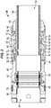
Figure 1 is an illustration of an example of a well system having a tool string with a retrievable cement bushing, according to an embodiment of the disclosure;Figure 2 is a cross-sectional view of an example of the retrievable cement bushing, according to an embodiment of the disclosure;Figure 3 is a cross-sectional view of an example of the retrievable cement bushing disposed in a surrounding well tubular, such as a surrounding packer body, according to an embodiment of the disclosure; andFigure 4 is a cross-sectional view of an example of the retrievable cement bushing disposed in a surrounding well tubular and having a slick joint extending therethrough, according to an embodiment of the disclosure.- In the following description, numerous details are set forth to provide an understanding of some embodiments of the present disclosure.
- The disclosure herein generally involves a system and methodology for pressure containment in a well via a retrievable cement bushing. The retrievable cement bushing comprises a body having an internal longitudinal passage. Seals may be used to form a sealing engagement with a surrounding wall of a downhole tubular system. The retrievable cement bushing further comprises an engagement lug which cooperates with a sleeve. In some applications, a plurality of the engagement lugs is arranged to provide engagement lugs spaced circumferentially around the body.
- The engagement lug (or lugs) is mounted on the body and is movable to a radially outward position for engagement with a corresponding portion of the surrounding wall, e.g a packer body wall. The sleeve is sized to receive a slick joint therethrough and is movable to a radially inward position relative to the engagement lug so as to hold the engagement lug in the radially outward position engaging the surrounding wall. The sleeve protects the slick joint from inwardly directed loading via the engagement lug when the retrievable cement bushing is subjected to differential pressures.
- The retrievable cement bushing may be used in a variety of applications. For example, the retrievable cement bushing may be used in a liner hanger running string to provide a temporary seal for pressure containment. The pressure containment allows a hydraulic liner hanger to be set before being disengaged and then retrieved to the surface after desired liner hanger operations have been carried out.
- As described in greater detail below, the retrievable cement bushing comprises a sleeve disposed at a radially inward position beneath the engagement lug or lugs while the engagement lug or lugs are engaged with a surrounding wall. The sleeve is positioned to block the engagement lug or lugs from acting against a slick joint during movement of the slick joint through an internal passage of the retrievable cement bushing. In other words, the sleeve absorbs the loading of the engagement lugs due to differential pressures acting on the retrievable cement bushing instead of allowing the engagement lugs to establish loads against the slick joint.
- The sleeve not only protects the slick joint from radially inward directed loads but also protects against premature release of the engagement lugs during axial movement of the slick joint through the retrievable cement bushing. With the sleeve in place beneath the engagement lugs, friction is not able to develop between the engagement lugs and the axially moving slick joint in a manner that could otherwise cause release of the engagement lugs. The construction of the retrievable cement bushing also allows the bushing to be locked in its profile in a surrounding wall, e.g. a surrounding packer wall. Depending on the application, the slick joint or another suitable tool may be used to actuate the retrievable cement bushing into the profile of the surrounding wall by causing radial expansion of the engagement lugs into the profile. The slick joint also may be used to lock the sleeve at the radially inward position beneath the engagement lugs of the retrievable cement bushing so that premature release does not occur.
- The retrievable cement bushing is useful in many applications were pressure integrity is desired. In cementing applications, for example, a liner hanger string is employed and comprises a running string used to run and set a liner hanger and a liner top packer. The running string is disconnected after the hanger is set. Following completion of a cementing operation, the running string is used to set the liner top packer and then is pulled out to the surface. In this type of application, the retrievable cement bushing is located at the interface of the running string and the packer (sometimes the hanger) to provide a seal barrier. If there is no seal at this interface, pumped fluids in the drill pipe are circulated up the annulus from the running string rather than being circulated down to the casing shoe for proper cementing of the liner string. The retrievable cement bushing also enables pressure testing of the packer from the annulus.
- While running downhole into the well in at least some applications, the retrievable cement bushing remains latched in its profile in a surrounding wall, e.g. in the surrounding wall of a packer, and provides a seal between itself and the surrounding wall. The retrievable cement bushing also may comprise internal seals which provide a seal between the retrievable cement bushing and a slick joint of a running string as the slick joint passes through the inside of the retrievable cement bushing. Thus, the retrievable cement bushing is able to provide external and internal seals while also taking the loading imparted due to pressures acting on the retrievable cement bushing. The retrievable cement bushing comprises at least one engagement lug which enables the retrievable cement bushing to be latched into the packer profile (or other suitable profile). The at least one engagement lug allows the retrievable cement bushing to be retrieved with minimal force applied during pulling of the running string out of hole.
- Referring generally to
Figure 1 , an example of awell system 20 is illustrated. Thewell system 20 comprises atool string 22 deployed in a surroundingtubular system 24 positioned within awellbore 26. Thewellbore 26 may be an open wellbore or a cased wellbore lined by acasing 28. In some embodiments, the surroundingtubular system 24 may comprise a liner system having a variety of components, including packers and other completion related components. Similarly,tool string 22 may comprise a variety of components, including a retrievable cement bushing 30. The retrievable cement bushing 30 may be releasably latched into a surroundingwall 32 of a component, e.g. packer, oftubular system 24 during running downhole intowellbore 26. - Depending on the application,
tool string 22 also may comprise other types of components. Examples of such components include ahydraulic running tool 34, aninternal packer 36, and ajunk bonnet 38. The various tool string components may be connected together by a variety of subs and/or other tubular components. The selection of tool string components can vary depending on the parameters of a given well servicing application. - Referring generally to
Figure 2 , an example of theretrievable cement bushing 30 is illustrated. In this example, theretrievable cement bushing 30 comprises abody 40 to which anengagement lug 42 is movably mounted. Theengagement lug 42 may be an individual engagement lug or a plurality of engagement lugs. In the specific embodiment illustrated, theengagement lug 42 comprises a plurality of engagement lugs 42 which are circumferentially mounted around thebody 40. The engagement lug or lugs 42 may be mounted for radial movement which is movement between a radially inward or retracted position and a radially outward or expanded position. However, the movement of the engagement lug or lugs 42 between the radially inward position and the radially outward position may be movement along a straight, angular, curved, or other suitable path depending on the structure ofbody 34 andengagement lug 42. - In the example illustrated in
Figure 2 , the plurality of engagement lugs 42 is movably mounted on acenter body portion 44 ofbody 40. Thecenter body portion 44 is constructed to guide the engagement lugs 42 as the engagement lugs 42 transition between their radially inward and radially outward positions. In some applications,body 40 also may comprise other components including atop adapter 46. Furthermore,body 40 comprises an internallongitudinal passage 48 extending therethrough. - The
retrievable cement bushing 30 also comprises asleeve 50 slidably mounted withinbody 40 for longitudinal movement along internallongitudinal passage 48. Thesleeve 50 has ahollow interior 52 generally aligned with and extending internallongitudinal passage 48 through theretrievable cement bushing 30. Thesleeve 50 is movable in a longitudinal direction to a radially inward position relative to the engagement lug or lugs 42. Once moved to the radially inward position, thesleeve 50 holds the engagement lug or lugs 42 in a radially outward position for engagement withwall 32. - In the example illustrated,
sleeve 50 further comprises a radially expandedportion 54 located to act against the engagement lugs 42 when thesleeve 50 is moved to the radially inward position illustrated inFigure 2 . The radially expandedportion 54 also may comprise alead end 56 having a slopedsurface 58. The slopedsurface 58 is oriented to facilitate transition of the engagement lugs 42 from a radially inward position to a radially outward position as thesleeve 50 is moved in a longitudinal direction to the illustrated radially inward position relative to engagement lugs 42. In many applications, movement of thesleeve 50 from a non-actuated position (engagement lugs 42 radially inward) to an actuated position (engagement lugs 42 radially outward) involves longitudinal movement of thesleeve 50 relative tobody 40 in an upward or uphole direction from a lead or bottom end of theretrievable cement bushing 30. - As illustrated, the
retrievable cement bushing 30 also may comprise aretention member 60 which releasably secures thesleeve 50 at the radially inward position relative to engagement lugs 42. Theretention member 60 may comprise an individual member or a plurality of members. For example, theretention member 60 may comprise aretainer 62 positioned betweensleeve 50 and the at least oneengagement lug 42. In the example illustrated, theretainer 62 comprises a C-ring 64 captured between aninternal feature 66 of the engagement lugs 42 and anexternal feature 68 of thesleeve 50 to releasably secure thesleeve 50 to the engagement lugs 42. Theretainer 62 may comprise a chamfered or otherwise slopedlead surface 70 oriented to facilitate further longitudinal movement ofsleeve 50 intobody 40 so as to shift the radially expandedportion 54 from beneath engagement lugs 42 and to thus release theretrievable cement bushing 30 from the surroundingwall 32 when theretrievable cement bushing 30 is to be retrieved uphole. - The
retention member 60 also may comprise at least one lockinglug 72 positioned to selectively lock thesleeve 50 at the radially inward position relative to the engagement lugs 42. In the illustrated example, a plurality of the locking lugs 72 is mounted tosleeve 50. By way of example, the locking lug or lugs 72 may be pivotably mounted tosleeve 50 for pivotable movement in a radially outward direction to a locked position, as illustrated inFigure 2 . In the locked position, each lockinglug 72 engages anabutment surface 74 of thecorresponding engagement lug 42 to secure thesleeve 50 and to thus lock the engagement lugs 42 in the radially outward position. Each lockinglug 72 also may comprise a sloped or otherwise configuredsurface 76 oriented to facilitate transition of the lockinglug 72 from an unlocked to a locked position, as explained in greater detail below. - The
retrievable cement bushing 30 also may comprise a variety of other features. For example, theretrievable cement bushing 30 may comprise an external seal or seals 78 positioned on thebody 40 to form a seal betweenbody 40 and the surroundingwall 32. Theretrievable cement bushing 30 also may comprise an internal seal or seals 80 mounted in thebody 50 along the internallongitudinal passage 48. The internal seal or seals 80 may be designed to form a seal between theretrievable cement bushing 30 and an internal slick joint slidably received along internallongitudinal passage 48, as described in greater detail below. The external andinternal seals body 40 and/or at other suitable locations alongretrievable cement bushing 30. - The
retrievable cement bushing 30 also may comprise other components, such as components to guide the engagement lugs 42 during translation between the radially inward and radially outward positions. For example, a slidingfeature 82, e.g. a plurality of slide pins, may be positioned at longitudinal ends of the engagement lug or lugs 42. The engagement lugs 42 also may be retained by atop retainer ring 84 and abottom retainer ring 86. The retainer rings 84, 86 secure the slidingfeatures 82 in a manner which facilitates sliding radial movement of the engagement lug or lugs 42. In the example illustrated, thebottom retainer ring 86 may be secured in place by anose member 88. Thenose member 88 also may have features which guide the radial movement of the engagement lugs 42 as they are moved between the radially inward and outward positions. A variety of fasteners, e.g. set screws, may be used to secure the bushing components when constructingretrievable cement bushing 30. For example, set screws or other fasteners may be used to securecenter body portion 44 withtop adapter 46,top retainer ring 84 withcenter body portion 44, andbottom retainer ring 86 withnose member 88. - With additional reference to
Figure 3 , theretrievable cement bushing 30 is illustrated as engaged with the surroundingwall 32. In this example, the surroundingwall 32 comprises a wall of apacker body 90 which forms part of apacker 92 of the surroundingtubular system 24. As illustrated, thewall 32 comprises a radiallyinward engagement feature 94 having a profile selected to latch with a radiallyoutward engagement feature 96 disposed along the radially outer surface of the engagement lug or lugs 42. In other words, theengagement feature 96 of engagement lugs 42 moves into engagement with thecorresponding engagement feature 94 ofwall 32/packer 92 to latch theretrievable cement bushing 30 at the desired location with respect to the surroundingwall 32 oftubular system 24. - For example, the
retrievable cement bushing 30 may be moved viatool string 22 into position within surroundingwall 32. Thesleeve 50 is then shifted longitudinally to the radially inward position relative to the surrounding engagement lugs 42. For example, thesleeve 50 may be pushed into thebody 40 from a bottom end so that theleading edge surface 58 of thesleeve 50 pushes the engagement lugs 42 outwardly to the illustrated, radially outward position in which engagement features 96 latch into corresponding engagement features 94 ofwall 32. (Thesleeve 50 may be shifted by a slick joint having an appropriate tool or by another suitable tool.) As thesleeve 50 is shifted longitudinally,retainer 62, e.g. C-ring 64, collapses and moves longitudinally until captured in position between theinternal feature 66 of the engagement lugs 42 and theexternal feature 68 ofsleeve 50. Theretainer 62 may be used to lock thesleeve 50 with respect to thebody 40 of theretrievable cement bushing 30 in one direction. - At this stage, a slick joint 98 can be installed through a top end of the
retrievable cement bushing 30 and moved longitudinally through theretrievable cement bushing 30 along internallongitudinal passage 48, as illustrated inFigure 4 . The slick joint 98 is sized and the engagement surfaces 76 of locking lugs 72 are oriented so that the slick joint 98 contacts surfaces 76 and forces the locking lugs 72 to pivot radially outwardly when the slick joint 98 is initially moved throughretrievable cement bushing 30 along internallongitudinal passage 48. Theretainer 62 effectively blocks movement of thesleeve 50 from the radially inward position while the slick joint 98 is being assembled. - Once the locking lugs 72 are shifted radially outward to their locking position, they work with
retainer 62 to lock thesleeve 50 against movement in both directions. At this stage, theretrievable cement bushing 30 is locked in position within surroundingwall 32 andsleeve 50 is similarly locked in position withinbody 40 to allow movement of the slick joint 98 up-and-down through thesleeve 50 and through the overallretrievable cement bushing 30. Thesleeve 50 blocks radially inward movement of engagement lugs 42 and thus prevents premature release of theretrievable cement bushing 26. Thesleeve 50 also protects the slick joint 98 from loading by the engagement lugs 42 during longitudinal movement of the slick joint through theretrievable cement bushing 30. - The
well system 20 may be formed with a wide variety of components for use in many types of environments and applications. For example, wellsystem 20 may comprise a variety of tubing strings, completion components, well servicing devices, and/or other components depending on the parameters of a given environment and application. Thewell system 20 also may be used in a variety of wells, including vertical wells, deviated wells, and multilateral wells. - Similarly, the
retrievable cement bushing 30 may utilize many types of components in various configurations and constructed from many types of materials. For example, the structure of the body and engagement lug or lugs may vary. Similarly, the seal systems may vary in structure, positioning, seal number, and arrangement. The engagement features and locking features on the sleeve, engagement lugs, and/or surrounding wall structure also may be designed according to the application, environment, and component arrangement. Additionally, the size, construction, and arrangement of many of the components can be selected based on numerous environmental parameters and other parameters of a given application. - Although a few embodiments of the disclosure have been described in detail above, those of ordinary skill in the art will readily appreciate that many modifications are possible without materially departing from the teachings of this disclosure. It is noted however that the scope of protection of the current invention is solely defined by the appended claims.
Claims (10)
- A system for containing pressure in a well, comprising:
a retrievable cement bushing (30) comprising:a body (40) having an internal longitudinal passage (48) therethrough;an engagement lug (42) mounted on the body, the engagement lug (42) being movable in a radially outward direction and having an outer engagement feature oriented to engage a corresponding feature in a surrounding wall (32);a sleeve (50) having a hollow interior (52) sized to receive a slick joint (98), the sleeve (50) being movable to a radially inward position relative to the engagement lug (42), the sleeve (50) holding the engagement lug (42) in a radially outward position when the sleeve (50) is located at the radially inward position;characterized bya retention member (60) comprising: a retainer (62) positioned between the sleeve (50) and the engagement lug (42) and at least one locking lug (72) pivotably mounted to the sleeve (50) for pivotable movement in a radially outward direction to a locked position, the at least one locking lug (72) being positioned to selectively lock the sleeve (50) at the radially inward position relative to the engagement lug (42). - The system as recited in claim 1, wherein the engagement lug (42) comprises a plurality of engagement lugs (42) circumferentially disposed about the body (40).
- The system as recited in claim 1, further comprising at least one of: an external seal (78) mounted on the body (40) and an internal seal (80) mounted on the body (40).
- The system as recited in claim 1, wherein the retainer (62) comprises a C-ring (64) captured between an internal feature of the engagement lug and an external feature of the sleeve to secure the sleeve to the engagement lug.
- The system as recited in claim 1, wherein the at least one locking lug (72) has a sloped surface oriented for engagement with the slick joint (98) such that movement of the slick joint (98) through the internal longitudinal passage (48) forces the at least one locking lug (72) radially outward to a locking position.
- A method, comprising:providing a retrievable cement bushing (30) with a body (40) and an engagement lug (42) mounted for movement in a generally radial direction with respect to the body (40);using a sleeve (50) along an internal longitudinal passage (48) of the body (40) to selectively hold the engagement lug (42) in a radially outward position for engagement with a corresponding engagement feature of a surrounding wall (32); andsecuring the sleeve (50) at a radially inward position relative to the engagement lug (42) via a retention member (60),
characterized in that the retention member (60) comprises: a retainer (62) positioned between the sleeve (50) and the engagement lug (42) and at least one locking lug (72) pivotably mounted to the sleeve (50) for pivotable movement in a radially outward direction to a locked position, the at least one locking lug (72) being positioned to selectively lock the sleeve (50) at the radially inward position relative to the engagement lug (42). - The method as recited in claim 6, further comprising mounting the retrievable cement bushing (30) into a tool string (22).
- The method as recited in claim 7, further comprising running the tool string (22) downhole into a wellbore and performing a cementing operation while containing pressure in the wellbore via the retrievable cement bushing (30), wherein the retainer (62) of the retention member (60) is in the form of a C-ring (64).
- The method as recited in claim 6, further comprising actuating the at least one locking lug (72) to a locked position via a slick joint (98).
- The method as recited in claim 6, wherein using the sleeve (50) comprises using the sleeve (50) to hold the engagement lug (42) in engagement with a surrounding packer body (90).
Applications Claiming Priority (1)
| Application Number | Priority Date | Filing Date | Title |
|---|---|---|---|
| PCT/US2014/035317WO2015163891A1 (en) | 2014-04-24 | 2014-04-24 | Retrievable cement bushing system and methodology |
Publications (3)
| Publication Number | Publication Date |
|---|---|
| EP3134606A1 EP3134606A1 (en) | 2017-03-01 |
| EP3134606A4 EP3134606A4 (en) | 2017-11-01 |
| EP3134606B1true EP3134606B1 (en) | 2020-02-05 |
Family
ID=54332922
Family Applications (1)
| Application Number | Title | Priority Date | Filing Date |
|---|---|---|---|
| EP14889953.7AActiveEP3134606B1 (en) | 2014-04-24 | 2014-04-24 | Retrievable cement bushing system and methodology |
Country Status (5)
| Country | Link |
|---|---|
| US (2) | US10145201B2 (en) |
| EP (1) | EP3134606B1 (en) |
| CA (1) | CA2946167C (en) |
| SA (1) | SA516380117B1 (en) |
| WO (1) | WO2015163891A1 (en) |
Families Citing this family (3)
| Publication number | Priority date | Publication date | Assignee | Title |
|---|---|---|---|---|
| US9938787B2 (en)* | 2016-02-10 | 2018-04-10 | Dril-Quip, Inc. | Fully supported c-ring slip retention system |
| AR119425A1 (en)* | 2019-07-19 | 2021-12-15 | Schlumberger Technology Bv | REMOVABLE ADAPTER FOR SHORT CASING HANGER SYSTEMS |
| CN120251150A (en)* | 2025-06-06 | 2025-07-04 | 淮北矿业股份有限公司 | A plugging device suitable for inclined drilling |
Family Cites Families (14)
| Publication number | Priority date | Publication date | Assignee | Title |
|---|---|---|---|---|
| US3920075A (en)* | 1974-02-08 | 1975-11-18 | Texas Iron Works | Method for positioning a liner on a tubular member in a well bore with a retrievable pack off bushing therebetween |
| US4562889A (en) | 1984-04-13 | 1986-01-07 | Braddick Britt O | Method and apparatus for rotating and reciprocating well bore liner |
| US4690220A (en) | 1985-05-01 | 1987-09-01 | Texas Iron Works, Inc. | Tubular member anchoring arrangement and method |
| US5472055A (en) | 1994-08-30 | 1995-12-05 | Smith International, Inc. | Liner hanger setting tool |
| US5884702A (en) | 1996-03-01 | 1999-03-23 | Smith International, Inc. | Liner assembly and method |
| US6302203B1 (en) | 2000-03-17 | 2001-10-16 | Schlumberger Technology Corporation | Apparatus and method for communicating with devices positioned outside a liner in a wellbore |
| US6655456B1 (en) | 2001-05-18 | 2003-12-02 | Dril-Quip, Inc. | Liner hanger system |
| US6695060B1 (en) | 2002-09-19 | 2004-02-24 | Michael J. Guidry, Jr. | Downhole pumping system |
| US7373988B2 (en) | 2003-09-05 | 2008-05-20 | Smith International, Inc. | Liner running system and method |
| US7581596B2 (en)* | 2006-03-24 | 2009-09-01 | Dril-Quip, Inc. | Downhole tool with C-ring closure seat and method |
| BRPI0705242B1 (en) | 2006-04-27 | 2018-02-06 | Dril-Quip, Inc. | COATING HANGER ASSEMBLY AND METHOD FOR OPERATING A WELL BACKGROUND HANGER ASSEMBLY |
| US8939220B2 (en) | 2010-01-07 | 2015-01-27 | Smith International, Inc. | Expandable slip ring for use with liner hangers and liner top packers |
| US8662178B2 (en)* | 2011-09-29 | 2014-03-04 | Halliburton Energy Services, Inc. | Responsively activated wellbore stimulation assemblies and methods of using the same |
| US9062520B2 (en)* | 2012-03-26 | 2015-06-23 | Schlumberger Technology Corporation | Retrievable cementing bushing system |
- 2014
- 2014-04-24USUS15/306,060patent/US10145201B2/ennot_activeExpired - Fee Related
- 2014-04-24EPEP14889953.7Apatent/EP3134606B1/enactiveActive
- 2014-04-24CACA2946167Apatent/CA2946167C/enactiveActive
- 2014-04-24WOPCT/US2014/035317patent/WO2015163891A1/enactiveApplication Filing
- 2016
- 2016-10-23SASA516380117Apatent/SA516380117B1/enunknown
- 2018
- 2018-11-20USUS16/196,994patent/US10301901B2/ennot_activeExpired - Fee Related
Non-Patent Citations (1)
| Title |
|---|
| None* |
Also Published As
| Publication number | Publication date |
|---|---|
| US20170044862A1 (en) | 2017-02-16 |
| US20190085653A1 (en) | 2019-03-21 |
| EP3134606A1 (en) | 2017-03-01 |
| EP3134606A4 (en) | 2017-11-01 |
| CA2946167A1 (en) | 2015-10-29 |
| SA516380117B1 (en) | 2022-12-26 |
| US10301901B2 (en) | 2019-05-28 |
| US10145201B2 (en) | 2018-12-04 |
| CA2946167C (en) | 2021-04-27 |
| WO2015163891A1 (en) | 2015-10-29 |
Similar Documents
| Publication | Publication Date | Title |
|---|---|---|
| US9447662B2 (en) | Abandonment and containment system for gas wells | |
| CA2153643C (en) | Sleeve valve flow control device with locator shifter | |
| US10240428B2 (en) | Packer assembly with thermal expansion buffers and isolation methods | |
| CA2434346C (en) | Retrievable packer having a positively operated support ring | |
| US9303477B2 (en) | Methods and apparatus for cementing wells | |
| EP2675985B1 (en) | Travel joint having an infinite slot mechanism for space out operations in a wellbore | |
| US8561690B2 (en) | Expansion cone assembly for setting a liner hanger in a wellbore casing | |
| US9587460B2 (en) | System and method for deploying a casing patch | |
| CN114364861B (en) | Ball tee release device | |
| US11492861B2 (en) | Packer assembly for use within a borehole | |
| CN108119107B (en) | Liner hanger setting tool and method of use thereof | |
| US10301901B2 (en) | Retrievable cement bushing system and methodology | |
| US20150060049A1 (en) | Retractable Collet Assembly for Liner String Installation in a Wellbore | |
| US8371388B2 (en) | Apparatus and method for installing a liner string in a wellbore casing | |
| US8936102B2 (en) | Packer assembly having barrel slips that divert axial loading to the wellbore | |
| US20150060086A1 (en) | Running Tool with Retractable Collet for Liner String Installation in a Wellbore | |
| NO341850B1 (en) | Packer assembly, barrel slip for a packer assembly, and method for diverting axial loading to a wellbore from a packer assembly | |
| US20250012157A1 (en) | Wellbore Tubular Anchor Sub and Seal for Modular Completion Interface | |
| WO2015034489A1 (en) | Running tool with retractable collet for liner string installation in a wellbore | |
| NO20240845A1 (en) | Single trip, debris tolerant lock mandrel with equalizing prong |
Legal Events
| Date | Code | Title | Description |
|---|---|---|---|
| STAA | Information on the status of an ep patent application or granted ep patent | Free format text:STATUS: THE INTERNATIONAL PUBLICATION HAS BEEN MADE | |
| PUAI | Public reference made under article 153(3) epc to a published international application that has entered the european phase | Free format text:ORIGINAL CODE: 0009012 | |
| STAA | Information on the status of an ep patent application or granted ep patent | Free format text:STATUS: REQUEST FOR EXAMINATION WAS MADE | |
| 17P | Request for examination filed | Effective date:20161021 | |
| AK | Designated contracting states | Kind code of ref document:A1 Designated state(s):AL AT BE BG CH CY CZ DE DK EE ES FI FR GB GR HR HU IE IS IT LI LT LU LV MC MK MT NL NO PL PT RO RS SE SI SK SM TR | |
| AX | Request for extension of the european patent | Extension state:BA ME | |
| RIN1 | Information on inventor provided before grant (corrected) | Inventor name:JAVED, ASIF Inventor name:HALL, JAMES | |
| DAX | Request for extension of the european patent (deleted) | ||
| REG | Reference to a national code | Ref country code:DE Ref legal event code:R079 Ref document number:602014060758 Country of ref document:DE Free format text:PREVIOUS MAIN CLASS: E21B0033120000 Ipc:E21B0033130000 | |
| A4 | Supplementary search report drawn up and despatched | Effective date:20171004 | |
| RIC1 | Information provided on ipc code assigned before grant | Ipc:E21B 23/02 20060101ALI20170927BHEP Ipc:E21B 33/13 20060101AFI20170927BHEP | |
| STAA | Information on the status of an ep patent application or granted ep patent | Free format text:STATUS: EXAMINATION IS IN PROGRESS | |
| 17Q | First examination report despatched | Effective date:20180620 | |
| GRAP | Despatch of communication of intention to grant a patent | Free format text:ORIGINAL CODE: EPIDOSNIGR1 | |
| STAA | Information on the status of an ep patent application or granted ep patent | Free format text:STATUS: GRANT OF PATENT IS INTENDED | |
| INTG | Intention to grant announced | Effective date:20190830 | |
| GRAS | Grant fee paid | Free format text:ORIGINAL CODE: EPIDOSNIGR3 | |
| GRAA | (expected) grant | Free format text:ORIGINAL CODE: 0009210 | |
| STAA | Information on the status of an ep patent application or granted ep patent | Free format text:STATUS: THE PATENT HAS BEEN GRANTED | |
| AK | Designated contracting states | Kind code of ref document:B1 Designated state(s):AL AT BE BG CH CY CZ DE DK EE ES FI FR GB GR HR HU IE IS IT LI LT LU LV MC MK MT NL NO PL PT RO RS SE SI SK SM TR | |
| REG | Reference to a national code | Ref country code:GB Ref legal event code:FG4D | |
| REG | Reference to a national code | Ref country code:AT Ref legal event code:REF Ref document number:1230017 Country of ref document:AT Kind code of ref document:T Effective date:20200215 | |
| REG | Reference to a national code | Ref country code:DE Ref legal event code:R096 Ref document number:602014060758 Country of ref document:DE | |
| REG | Reference to a national code | Ref country code:IE Ref legal event code:FG4D | |
| REG | Reference to a national code | Ref country code:CH Ref legal event code:EP | |
| REG | Reference to a national code | Ref country code:NO Ref legal event code:T2 Effective date:20200205 | |
| REG | Reference to a national code | Ref country code:NL Ref legal event code:MP Effective date:20200205 | |
| PG25 | Lapsed in a contracting state [announced via postgrant information from national office to epo] | Ref country code:PT Free format text:LAPSE BECAUSE OF FAILURE TO SUBMIT A TRANSLATION OF THE DESCRIPTION OR TO PAY THE FEE WITHIN THE PRESCRIBED TIME-LIMIT Effective date:20200628 Ref country code:RS Free format text:LAPSE BECAUSE OF FAILURE TO SUBMIT A TRANSLATION OF THE DESCRIPTION OR TO PAY THE FEE WITHIN THE PRESCRIBED TIME-LIMIT Effective date:20200205 Ref country code:FI Free format text:LAPSE BECAUSE OF FAILURE TO SUBMIT A TRANSLATION OF THE DESCRIPTION OR TO PAY THE FEE WITHIN THE PRESCRIBED TIME-LIMIT Effective date:20200205 | |
| REG | Reference to a national code | Ref country code:LT Ref legal event code:MG4D | |
| PG25 | Lapsed in a contracting state [announced via postgrant information from national office to epo] | Ref country code:HR Free format text:LAPSE BECAUSE OF FAILURE TO SUBMIT A TRANSLATION OF THE DESCRIPTION OR TO PAY THE FEE WITHIN THE PRESCRIBED TIME-LIMIT Effective date:20200205 Ref country code:IS Free format text:LAPSE BECAUSE OF FAILURE TO SUBMIT A TRANSLATION OF THE DESCRIPTION OR TO PAY THE FEE WITHIN THE PRESCRIBED TIME-LIMIT Effective date:20200605 Ref country code:GR Free format text:LAPSE BECAUSE OF FAILURE TO SUBMIT A TRANSLATION OF THE DESCRIPTION OR TO PAY THE FEE WITHIN THE PRESCRIBED TIME-LIMIT Effective date:20200506 Ref country code:BG Free format text:LAPSE BECAUSE OF FAILURE TO SUBMIT A TRANSLATION OF THE DESCRIPTION OR TO PAY THE FEE WITHIN THE PRESCRIBED TIME-LIMIT Effective date:20200505 Ref country code:LV Free format text:LAPSE BECAUSE OF FAILURE TO SUBMIT A TRANSLATION OF THE DESCRIPTION OR TO PAY THE FEE WITHIN THE PRESCRIBED TIME-LIMIT Effective date:20200205 Ref country code:SE Free format text:LAPSE BECAUSE OF FAILURE TO SUBMIT A TRANSLATION OF THE DESCRIPTION OR TO PAY THE FEE WITHIN THE PRESCRIBED TIME-LIMIT Effective date:20200205 | |
| PGFP | Annual fee paid to national office [announced via postgrant information from national office to epo] | Ref country code:GB Payment date:20200520 Year of fee payment:7 | |
| PG25 | Lapsed in a contracting state [announced via postgrant information from national office to epo] | Ref country code:NL Free format text:LAPSE BECAUSE OF FAILURE TO SUBMIT A TRANSLATION OF THE DESCRIPTION OR TO PAY THE FEE WITHIN THE PRESCRIBED TIME-LIMIT Effective date:20200205 | |
| PG25 | Lapsed in a contracting state [announced via postgrant information from national office to epo] | Ref country code:CZ Free format text:LAPSE BECAUSE OF FAILURE TO SUBMIT A TRANSLATION OF THE DESCRIPTION OR TO PAY THE FEE WITHIN THE PRESCRIBED TIME-LIMIT Effective date:20200205 Ref country code:RO Free format text:LAPSE BECAUSE OF FAILURE TO SUBMIT A TRANSLATION OF THE DESCRIPTION OR TO PAY THE FEE WITHIN THE PRESCRIBED TIME-LIMIT Effective date:20200205 Ref country code:SM Free format text:LAPSE BECAUSE OF FAILURE TO SUBMIT A TRANSLATION OF THE DESCRIPTION OR TO PAY THE FEE WITHIN THE PRESCRIBED TIME-LIMIT Effective date:20200205 Ref country code:EE Free format text:LAPSE BECAUSE OF FAILURE TO SUBMIT A TRANSLATION OF THE DESCRIPTION OR TO PAY THE FEE WITHIN THE PRESCRIBED TIME-LIMIT Effective date:20200205 Ref country code:DK Free format text:LAPSE BECAUSE OF FAILURE TO SUBMIT A TRANSLATION OF THE DESCRIPTION OR TO PAY THE FEE WITHIN THE PRESCRIBED TIME-LIMIT Effective date:20200205 Ref country code:ES Free format text:LAPSE BECAUSE OF FAILURE TO SUBMIT A TRANSLATION OF THE DESCRIPTION OR TO PAY THE FEE WITHIN THE PRESCRIBED TIME-LIMIT Effective date:20200205 Ref country code:LT Free format text:LAPSE BECAUSE OF FAILURE TO SUBMIT A TRANSLATION OF THE DESCRIPTION OR TO PAY THE FEE WITHIN THE PRESCRIBED TIME-LIMIT Effective date:20200205 Ref country code:SK Free format text:LAPSE BECAUSE OF FAILURE TO SUBMIT A TRANSLATION OF THE DESCRIPTION OR TO PAY THE FEE WITHIN THE PRESCRIBED TIME-LIMIT Effective date:20200205 | |
| REG | Reference to a national code | Ref country code:DE Ref legal event code:R119 Ref document number:602014060758 Country of ref document:DE | |
| REG | Reference to a national code | Ref country code:AT Ref legal event code:MK05 Ref document number:1230017 Country of ref document:AT Kind code of ref document:T Effective date:20200205 | |
| PG25 | Lapsed in a contracting state [announced via postgrant information from national office to epo] | Ref country code:MC Free format text:LAPSE BECAUSE OF FAILURE TO SUBMIT A TRANSLATION OF THE DESCRIPTION OR TO PAY THE FEE WITHIN THE PRESCRIBED TIME-LIMIT Effective date:20200205 | |
| REG | Reference to a national code | Ref country code:CH Ref legal event code:PL | |
| PLBE | No opposition filed within time limit | Free format text:ORIGINAL CODE: 0009261 | |
| STAA | Information on the status of an ep patent application or granted ep patent | Free format text:STATUS: NO OPPOSITION FILED WITHIN TIME LIMIT | |
| 26N | No opposition filed | Effective date:20201106 | |
| PG25 | Lapsed in a contracting state [announced via postgrant information from national office to epo] | Ref country code:AT Free format text:LAPSE BECAUSE OF FAILURE TO SUBMIT A TRANSLATION OF THE DESCRIPTION OR TO PAY THE FEE WITHIN THE PRESCRIBED TIME-LIMIT Effective date:20200205 Ref country code:IT Free format text:LAPSE BECAUSE OF FAILURE TO SUBMIT A TRANSLATION OF THE DESCRIPTION OR TO PAY THE FEE WITHIN THE PRESCRIBED TIME-LIMIT Effective date:20200205 Ref country code:DE Free format text:LAPSE BECAUSE OF NON-PAYMENT OF DUE FEES Effective date:20201103 Ref country code:LU Free format text:LAPSE BECAUSE OF NON-PAYMENT OF DUE FEES Effective date:20200424 Ref country code:FR Free format text:LAPSE BECAUSE OF NON-PAYMENT OF DUE FEES Effective date:20200430 Ref country code:LI Free format text:LAPSE BECAUSE OF NON-PAYMENT OF DUE FEES Effective date:20200430 Ref country code:CH Free format text:LAPSE BECAUSE OF NON-PAYMENT OF DUE FEES Effective date:20200430 | |
| REG | Reference to a national code | Ref country code:BE Ref legal event code:MM Effective date:20200430 | |
| PG25 | Lapsed in a contracting state [announced via postgrant information from national office to epo] | Ref country code:PL Free format text:LAPSE BECAUSE OF FAILURE TO SUBMIT A TRANSLATION OF THE DESCRIPTION OR TO PAY THE FEE WITHIN THE PRESCRIBED TIME-LIMIT Effective date:20200205 Ref country code:BE Free format text:LAPSE BECAUSE OF NON-PAYMENT OF DUE FEES Effective date:20200430 Ref country code:SI Free format text:LAPSE BECAUSE OF FAILURE TO SUBMIT A TRANSLATION OF THE DESCRIPTION OR TO PAY THE FEE WITHIN THE PRESCRIBED TIME-LIMIT Effective date:20200205 | |
| PG25 | Lapsed in a contracting state [announced via postgrant information from national office to epo] | Ref country code:IE Free format text:LAPSE BECAUSE OF NON-PAYMENT OF DUE FEES Effective date:20200424 | |
| GBPC | Gb: european patent ceased through non-payment of renewal fee | Effective date:20210424 | |
| PG25 | Lapsed in a contracting state [announced via postgrant information from national office to epo] | Ref country code:GB Free format text:LAPSE BECAUSE OF NON-PAYMENT OF DUE FEES Effective date:20210424 | |
| PG25 | Lapsed in a contracting state [announced via postgrant information from national office to epo] | Ref country code:TR Free format text:LAPSE BECAUSE OF FAILURE TO SUBMIT A TRANSLATION OF THE DESCRIPTION OR TO PAY THE FEE WITHIN THE PRESCRIBED TIME-LIMIT Effective date:20200205 Ref country code:MT Free format text:LAPSE BECAUSE OF FAILURE TO SUBMIT A TRANSLATION OF THE DESCRIPTION OR TO PAY THE FEE WITHIN THE PRESCRIBED TIME-LIMIT Effective date:20200205 Ref country code:CY Free format text:LAPSE BECAUSE OF FAILURE TO SUBMIT A TRANSLATION OF THE DESCRIPTION OR TO PAY THE FEE WITHIN THE PRESCRIBED TIME-LIMIT Effective date:20200205 | |
| PG25 | Lapsed in a contracting state [announced via postgrant information from national office to epo] | Ref country code:MK Free format text:LAPSE BECAUSE OF FAILURE TO SUBMIT A TRANSLATION OF THE DESCRIPTION OR TO PAY THE FEE WITHIN THE PRESCRIBED TIME-LIMIT Effective date:20200205 Ref country code:AL Free format text:LAPSE BECAUSE OF FAILURE TO SUBMIT A TRANSLATION OF THE DESCRIPTION OR TO PAY THE FEE WITHIN THE PRESCRIBED TIME-LIMIT Effective date:20200205 | |
| P01 | Opt-out of the competence of the unified patent court (upc) registered | Effective date:20231208 | |
| PGFP | Annual fee paid to national office [announced via postgrant information from national office to epo] | Ref country code:NO Payment date:20250409 Year of fee payment:12 |