EP3131614B1 - Intravenous catheter apparatus - Google Patents
Intravenous catheter apparatusDownload PDFInfo
- Publication number
- EP3131614B1 EP3131614B1EP16705703.3AEP16705703AEP3131614B1EP 3131614 B1EP3131614 B1EP 3131614B1EP 16705703 AEP16705703 AEP 16705703AEP 3131614 B1EP3131614 B1EP 3131614B1
- Authority
- EP
- European Patent Office
- Prior art keywords
- needle
- proximal
- catheter
- distal
- chamber
- Prior art date
- Legal status (The legal status is an assumption and is not a legal conclusion. Google has not performed a legal analysis and makes no representation as to the accuracy of the status listed.)
- Active
Links
- 238000001990intravenous administrationMethods0.000titleclaimsdescription26
- 239000012530fluidSubstances0.000claimsdescription6
- 230000000717retained effectEffects0.000claimsdescription6
- 238000007373indentationMethods0.000claimsdescription4
- 230000000295complement effectEffects0.000claimsdescription3
- 239000000463materialSubstances0.000description8
- 230000008901benefitEffects0.000description4
- 238000004519manufacturing processMethods0.000description4
- 238000010276constructionMethods0.000description3
- 230000007423decreaseEffects0.000description3
- 238000003780insertionMethods0.000description2
- 230000037431insertionEffects0.000description2
- 238000012986modificationMethods0.000description2
- 230000004048modificationEffects0.000description2
- 238000007789sealingMethods0.000description2
- 210000003462veinAnatomy0.000description2
- 238000003466weldingMethods0.000description2
- 208000035049Blood-Borne InfectionsDiseases0.000description1
- 208000027418Wounds and injuryDiseases0.000description1
- 239000000853adhesiveSubstances0.000description1
- 230000001070adhesive effectEffects0.000description1
- 230000004888barrier functionEffects0.000description1
- 230000005540biological transmissionEffects0.000description1
- 230000008859changeEffects0.000description1
- 238000002788crimpingMethods0.000description1
- 230000006378damageEffects0.000description1
- 238000001746injection mouldingMethods0.000description1
- 208000014674injuryDiseases0.000description1
- 239000002184metalSubstances0.000description1
- 238000000034methodMethods0.000description1
- 238000000465mouldingMethods0.000description1
- 230000008569processEffects0.000description1
- 230000001012protectorEffects0.000description1
- 230000002792vascularEffects0.000description1
Images

Classifications
- A—HUMAN NECESSITIES
- A61—MEDICAL OR VETERINARY SCIENCE; HYGIENE
- A61M—DEVICES FOR INTRODUCING MEDIA INTO, OR ONTO, THE BODY; DEVICES FOR TRANSDUCING BODY MEDIA OR FOR TAKING MEDIA FROM THE BODY; DEVICES FOR PRODUCING OR ENDING SLEEP OR STUPOR
- A61M25/00—Catheters; Hollow probes
- A61M25/01—Introducing, guiding, advancing, emplacing or holding catheters
- A61M25/06—Body-piercing guide needles or the like
- A61M25/0612—Devices for protecting the needle; Devices to help insertion of the needle, e.g. wings or holders
- A61M25/0618—Devices for protecting the needle; Devices to help insertion of the needle, e.g. wings or holders having means for protecting only the distal tip of the needle, e.g. a needle guard
- A—HUMAN NECESSITIES
- A61—MEDICAL OR VETERINARY SCIENCE; HYGIENE
- A61M—DEVICES FOR INTRODUCING MEDIA INTO, OR ONTO, THE BODY; DEVICES FOR TRANSDUCING BODY MEDIA OR FOR TAKING MEDIA FROM THE BODY; DEVICES FOR PRODUCING OR ENDING SLEEP OR STUPOR
- A61M25/00—Catheters; Hollow probes
- A61M25/0097—Catheters; Hollow probes characterised by the hub
- A—HUMAN NECESSITIES
- A61—MEDICAL OR VETERINARY SCIENCE; HYGIENE
- A61M—DEVICES FOR INTRODUCING MEDIA INTO, OR ONTO, THE BODY; DEVICES FOR TRANSDUCING BODY MEDIA OR FOR TAKING MEDIA FROM THE BODY; DEVICES FOR PRODUCING OR ENDING SLEEP OR STUPOR
- A61M25/00—Catheters; Hollow probes
- A61M25/01—Introducing, guiding, advancing, emplacing or holding catheters
- A61M25/06—Body-piercing guide needles or the like
- A61M25/0606—"Over-the-needle" catheter assemblies, e.g. I.V. catheters
- A—HUMAN NECESSITIES
- A61—MEDICAL OR VETERINARY SCIENCE; HYGIENE
- A61M—DEVICES FOR INTRODUCING MEDIA INTO, OR ONTO, THE BODY; DEVICES FOR TRANSDUCING BODY MEDIA OR FOR TAKING MEDIA FROM THE BODY; DEVICES FOR PRODUCING OR ENDING SLEEP OR STUPOR
- A61M25/00—Catheters; Hollow probes
- A61M25/01—Introducing, guiding, advancing, emplacing or holding catheters
- A61M25/06—Body-piercing guide needles or the like
- A61M25/0612—Devices for protecting the needle; Devices to help insertion of the needle, e.g. wings or holders
- A61M25/0637—Butterfly or winged devices, e.g. for facilitating handling or for attachment to the skin
Definitions
- the inventiongenerally relates to an intravenous catheter apparatus. More particularly, the invention relates to an intravenous catheter apparatus comprising a catheter hub arranged at a proximal end of a catheter tube and having an inner surface defining a housing; a needle having a needle tip and extending through the housing and the catheter tube when in a ready position; and a needle guard slidably arranged on the needle and received in the housing when the needle is in its ready position, wherein the needle guard is configured to guard the needle tip upon withdrawal of the needle from the catheter hub.
- An intravenous catheter apparatus of this kindis generally known.
- the needle guardserves to prevent a person handling the intravenous catheter apparatus from accidentally coming into contact with the needle tip after placement of the catheter tube in and subsequent removal of the needle from a patient's vein. Thereby, the intravenous catheter apparatus helps to avoid unwanted transmission of blood borne diseases.
- the needlewhen the needle is withdrawn from a patient, the needle grates or otherwise causes friction or creates a drag as it slides / passes through a catheter, a catheter hub or through a needle guard creating drag or a withdrawal force.
- US 2015/0151058 A1discloses a safety needle assembly having a first hub attached to a flexible tube and a second hub attached to a needle projecting through the flexible tube.
- a needle guardis positioned in an interior cavity of the first hub.
- the needle guardhas a proximal wall having an opening and two arms each with an end and wherein the two ends are spaced from and biased toward the needle in a ready position.
- US 2009/0281499 A1relates to a safety clip device for shielding and retaining a tip of an introducer needle following the insertion of a vascular catheter.
- the safety clip deviceincludes a sleeve having an interlock system for locking together the sleeve and the catheter adapter.
- the sleevehouses a safety clip wherein a portion of the introducer needle extends through the safety clip and is pinched between the arm portions of the safety clip.
- the tip of the introducer needleis withdrawn from the catheter adapter, the tip of the introducer needle is retained in the safety clip, whereafter the safety clip is retained within the sleeve and the sleeve is released from the catheter adapter for safe disposal.
- WO 2013/190407 A1relates to a needle guard for use in a medical device, in particular for in particular for use in a catheter device, including a base portion having a needle passage extending in an axial direction from a proximal side of said base portion through said base portion to a distal side of said base portion wherein a needle shaft having a principle outer profile can be movably arranged in said needle passage; first and second arms extending substantially in said axial direction from said distal side of said base portion, wherein said first arm has a distal region and a proximal region; and a distal wall transversely arranged at said distal region of said first arm.
- EP 1 803 477 A2discloses a needle tip protector including a pair of aperture members with spring arms urging the aperture members out of alignment to create a barrier for a needle tip.
- a primary object and advantage of the present inventionis to provide an intravenous catheter apparatus that significantly decreases the withdrawal force required and friction caused as a needle is withdrawn through a catheter hub being protected by a needle guard.
- Another object and advantage of the present inventionis to provide an improved intravenous catheter apparatus which is inexpensive to manufacture, efficient, effective and simple in its construction and use.
- the present inventionrelates to an intravenous catheter apparatus comprising: a catheter tube; a catheter hub having a distal section and a proximal section, wherein the distal section is joined to the catheter tube and the proximal section defines a housing; a needle extending through the catheter hub and the catheter tube and defining an axial direction, wherein the needle has opposite proximal and distal ends, the distal end forming a needle tip; a needle hub attached to the proximal end of the needle; a needle guard slidably arranged on the needle, wherein the needle guard is movably retained in the housing of the catheter hub when the needle extends through the catheter hub and the catheter tube, and wherein the needle guard is removable from the catheter hub once the needle tip is received in the needle guard upon withdrawal of the needle from the catheter tube; and wherein the housing defines a chamber at one end thereof ensuring that a first and second arms of the needle guard do not engage or interact with an inner surface of the chamber prior and during venipuncture of a
- the needlemay have a needle feature close to its needle tip, which interacts with a proportional base of the needle guard, e.g. a curving or a bulge or any other change in profile. Thereby, it can be prevented that the needle is retracted out of the needle guard, which is known in the art.
- a proportional base of the needle guarde.g. a curving or a bulge or any other change in profile.
- the catheter hubis made of two parts, a first part having a distal end section and a second part having a proximal end section.
- the first and second partsdefine the housing to receive the needle guard which is movably arranged on the needle shaft.
- the chamberis formed by an indentation in the housing for accommodating the first and second arm such that none of the arms deflected by the needle contacts an inner surface of the chamber. Through such indentation the overall outer dimensions of the housing and the catheter hub can be kept small, while it is still provided that the first and second arm of the needle guard do not contact the inner wall surface of the chamber.
- first and second parts of the catheter hubmay be joined by complementary end portions, which preferably as such extend at an angle with regard to the axial direction. This ensures that both parts are aligned concentrically towards each other. Thereby, the assembly of such a catheter hub can be made easier.
- end portionsmay be stepped, which enlarges their contact area for a better mutual interconnection.
- the first and second partmay form the chamber, in particular, the distal end section of the first part and the proximal end section of the second part may form the chamber, which ensures that no undercut has to be formed in either one of the first and second part.
- the inner surface of the chambermay be parallel to the axial direction and defined only by one of the first or second part.
- the inner surface of the chamberis defined by either the distal end section of the first part or the proximal end section of the second part. More preferably the inner surface of the chamber is defined by the proximal end section of the second part.
- the intravenous catheter apparatusmay be provided such that the other one of the first or second part comprises a surface joined with the inner surface of the one of the first or second part, which surface is inclined towards the inside of the housing in a proximal direction of the catheter hub, wherein the surface has a smaller inside diameter at its innermost end than a distance between outermost points of the arms in their deflected state inside the chamber.
- the first partcomprises the surface joined with the inner surface of the second part.
- the distal end section of the first partcomprises the surface joined with the inner surface of the proximal end section of the second part.
- Such a surfaceserves as a stop for the arms in their deflected state such that they cannot be pulled out of the catheter hub in the proximal axial direction as long as the needle deflects them outward in the ready position of the needle guard.
- the inclination of the surfacesupports that the arms are directed inwards when the needle guard is pulled out in the retracted position, even if they have been plastically deformed by the needle in their deflected state.
- proximalrefers to a region of the device or parts thereof or a location on the device which is closest to, for example, a user using the device.
- distalrefers to a region of the device which is farthest from the user, for example, the distal region of a needle will be the region of the needle containing the needle tip which is to be inserted e.g. into a patient's vein.
- the intravenous catheter apparatus 10includes a catheter hub 12 having a fluid path 11, a catheter tube 14 and a needle 20.
- the catheter hub 12has a distal end 22 and a proximal end 24, wherein the catheter tube 14 is arranged adjacent to the distal end 22 of the catheter hub 12.
- the needle 20has a needle shaft 28, a needle tip at a distal section of the needle shaft 28 and a needle hub 16 attached to a proximal section 36 of the needle shaft 28.
- An enlargement (not shown) of the needle 20is provided between the distal section and the proximal section 36 of the needle shaft 28.
- the enlargementhas a maximum dimension in a direction transverse to the needle shaft 28, which is greater than the outer diameter of the distal or proximal section 36.
- the enlargementcan be made, for example, by crimping the needle shaft 28.
- a needle guard 26is movably arranged on the needle shaft 28 and retained in the catheter hub 12 prior to use of the catheter apparatus 10 as shown in Fig. 3 .
- the needle guard 26has a base portion 44, a first arm 40, a second arm 42 and a distal wall 18.
- the distal wall 18is arranged at a distal end of the first arm 40 and extends in a direction transverse to an axial direction A of the needle 20.
- a tension element 46for example, a rubber band or the like, surrounds the first and second arms 40, 42.
- the first and second arms 40, 42 of the needle guard 26extend generally in the axial direction A from a distal side 60 of the base portion 44, i.e. generally parallel to the needle shaft 28.
- the needle shaft 28moves relative to the needle guard 26 until the needle tip is received in the needle guard 26.
- the enlargement of the needle shaft 28engages with the base portion 44 of the needle guard 26 via a stopping element 38 such that the needle guard 26 can be pulled out of the catheter hub 12 together with the needle 20.
- An axial movement of the needle 20 relative to the needle guard 26is now limited, as the distal wall 18 blocks the needle tip axially and the engagement between the enlargement and the base portion 44 via the stopping element 38 prevents the needle tip from being removed via the base portion 44, i.e. the needle tip is safely surrounded by the needle guard 26.
- the catheter hub 12is made of two parts, i.e. a first part 12a and a second part 12b comprising the fluid path 11.
- the first part 12ahas a distal end section 50 and the second part 12b has a proximal end section 52.
- the first part 12ais part of a housing 48 to receive a needle guard 26 which is movably arranged on the needle shaft 28 of the needle 20.
- the distal end 22 of the second part 12bis connected to a catheter tube 14.
- the distal end section 50 of the first part 12ais configured to be assembled with the proximal end section 52 of the second part 12b in various ways in a fluid tight manner, such as by adhesive sealing, ultrasonic welding, heated die, radio frequency sealing, mechanical seal (snap fit), insert molding, laser welding etc., ensuring a leak free joint. It is also possible to join the two parts 12a, 12b to one another, for example, using threads, interference, or snap-fit. In particular, as can be seen in Figs. 2 and 3 , the first and second parts 12a and 12b are joined by complementary stepped end portions
- the housing 48is defined by the first and second parts 12a and 12b of the catheter hub 12 that houses the needle guard 26 and is configured such that it defines a chamber 54 at one end of the second part 12b.
- the chamber 54is configured to provide room/space for the needle guard 26 in its ready position.
- the chamber 54is formed by an indentation in the housing 48 for accommodating the first and second arms 40 and 42 such that none of the arms 40 and 42 deflected by the needle 20 contact the inner surface 56 of the chamber 54.
- the chamber 54is arranged in the proximal end section 52 of the second part 12b and defined by the first and second parts 12a and 12b, which are stuck together in axial direction by means of stepped surface areas 57, 59 of the two parts 12a, 12b.
- the first arm 40deflects outward of the needle guard 26 such that the distal wall 18 of the first arm 40 is supported on the needle shaft 28. Further, in this ready position, the first and second arms 40, 42 do not engage or interact with an inner wall/surface 56 of the chamber 54 prior and during venipuncture of a patient.
- the inner surface 56is parallel to the axial direction A and defined only by the second part 12b. This non-contact of the first and second arms 40, 42 with the inner surface 56 of the chamber 54 significantly decreases the withdrawal force required and friction caused when a needle 20 is withdrawn through a catheter hub 12 being protected by a needle guard 26 after use.
- the first part 12acomprises a surface 58 which is inclined towards the inside of the housing 48 in a proximal direction of the catheter hub 12.
- This chamfered surface 58forms a radial shoulder and serves as an axial stop in the proximal direction of the catheter hub 12 for the arms 40, 42 in their ready position.
- the surface 58has a smaller inside diameter at its innermost end than a distance between outermost points of the arms 40 and 42 in their deflected state inside the chamber 54. In other words, the arms 40, 42 cannot pass this surface 58 in the ready position, as shown in Fig. 3 . However, in this retracted position, the arms 40, 42 have swung radially inwardly and can pass the chamfered surface 58.
- the needle guard 26is arranged in the catheter hub 12 near a proximal end 24 of the needle shaft 28.
- the needle 20extends completely through the needle guard 26, thereby deflecting the first arm 40 of the needle guard 26 outwards, i.e. at an angle to the axial direction A, such that the distal wall 18 of the first arm 40 is supported on the needle shaft 28.
- the needle 20is withdrawn from the catheter tube 14 and the needle shaft 28 moves through the needle guard 26 while the needle guard 26 is retained in the catheter hub 12.
- a restoring force of the tension element 46 and the first arm's 40 inherent elasticityensure that the first arm 40 of the needle guard 26 is moved back into alignment with the axial direction A, so that the needle tip is blocked by being axially covered by the distal wall 18 of the needle guard 26, i.e. the needle tip is prevented from axially projecting out of the needle guard 26.
- the catheter apparatus 10is particularly inexpensive to manufacture if the base portion 44, the first and second arms 40, 42 are integrally made from a first material.
- the first materialmay, for example, be a plastic material.
- the base portion 44, the first and second arms 40, 42could be manufactured by injection molding.
- the base portion 44, and one of the first and second arms 40, 42could be integrally made from a first material, e.g. a plastic material, and the other one of the first and second arms 40, 42 could be made from a second material different from said first material.
- said other one of the first and second arms 40, 42could include a strip of material having spring-like properties, e.g. a strip of sheet metal, providing the above-mentioned inherent elasticity.
- the construction and shape of the improved intravenous catheter apparatus 10 of the present disclosureprovides a simple configuration.
- the simple design of the intravenous catheter apparatus 10is advantageous in a clinical setting because it smoothens the whole catheterization process thereby reducing injury or discomfort to a patient.
- such designgreatly reduces manufacturing costs and is efficient, effective and simple in its construction and use.
Landscapes
- Health & Medical Sciences (AREA)
- Life Sciences & Earth Sciences (AREA)
- Biophysics (AREA)
- Pulmonology (AREA)
- Engineering & Computer Science (AREA)
- Anesthesiology (AREA)
- Biomedical Technology (AREA)
- Heart & Thoracic Surgery (AREA)
- Hematology (AREA)
- Animal Behavior & Ethology (AREA)
- General Health & Medical Sciences (AREA)
- Public Health (AREA)
- Veterinary Medicine (AREA)
- Infusion, Injection, And Reservoir Apparatuses (AREA)
- Media Introduction/Drainage Providing Device (AREA)
Description
- The invention generally relates to an intravenous catheter apparatus. More particularly, the invention relates to an intravenous catheter apparatus comprising a catheter hub arranged at a proximal end of a catheter tube and having an inner surface defining a housing; a needle having a needle tip and extending through the housing and the catheter tube when in a ready position; and a needle guard slidably arranged on the needle and received in the housing when the needle is in its ready position, wherein the needle guard is configured to guard the needle tip upon withdrawal of the needle from the catheter hub.
- An intravenous catheter apparatus of this kind is generally known. The needle guard serves to prevent a person handling the intravenous catheter apparatus from accidentally coming into contact with the needle tip after placement of the catheter tube in and subsequent removal of the needle from a patient's vein. Thereby, the intravenous catheter apparatus helps to avoid unwanted transmission of blood borne diseases.
- Generally, when the needle is withdrawn from a patient, the needle grates or otherwise causes friction or creates a drag as it slides / passes through a catheter, a catheter hub or through a needle guard creating drag or a withdrawal force.
- It is desired to provide an intravenous catheter apparatus that significantly decreases the withdrawal force required and friction caused as a needle is withdrawn through a catheter hub being protected by a needle guard.
US 2015/0151058 A1 discloses a safety needle assembly having a first hub attached to a flexible tube and a second hub attached to a needle projecting through the flexible tube. A needle guard is positioned in an interior cavity of the first hub. The needle guard has a proximal wall having an opening and two arms each with an end and wherein the two ends are spaced from and biased toward the needle in a ready position.US 2009/0281499 A1 relates to a safety clip device for shielding and retaining a tip of an introducer needle following the insertion of a vascular catheter. The safety clip device includes a sleeve having an interlock system for locking together the sleeve and the catheter adapter. The sleeve houses a safety clip wherein a portion of the introducer needle extends through the safety clip and is pinched between the arm portions of the safety clip. As the tip of the introducer needle is withdrawn from the catheter adapter, the tip of the introducer needle is retained in the safety clip, whereafter the safety clip is retained within the sleeve and the sleeve is released from the catheter adapter for safe disposal.WO 2013/190407 A1 relates to a needle guard for use in a medical device, in particular for in particular for use in a catheter device, including a base portion having a needle passage extending in an axial direction from a proximal side of said base portion through said base portion to a distal side of said base portion wherein a needle shaft having a principle outer profile can be movably arranged in said needle passage; first and second arms extending substantially in said axial direction from said distal side of said base portion, wherein said first arm has a distal region and a proximal region; and a distal wall transversely arranged at said distal region of said first arm.EP 1 803 477 A2 discloses a needle tip protector including a pair of aperture members with spring arms urging the aperture members out of alignment to create a barrier for a needle tip.- A primary object and advantage of the present invention is to provide an intravenous catheter apparatus that significantly decreases the withdrawal force required and friction caused as a needle is withdrawn through a catheter hub being protected by a needle guard.
- Another object and advantage of the present invention is to provide an improved intravenous catheter apparatus which is inexpensive to manufacture, efficient, effective and simple in its construction and use.
- Accordingly, the present invention relates to an intravenous catheter apparatus comprising: a catheter tube; a catheter hub having a distal section and a proximal section, wherein the distal section is joined to the catheter tube and the proximal section defines a housing; a needle extending through the catheter hub and the catheter tube and defining an axial direction, wherein the needle has opposite proximal and distal ends, the distal end forming a needle tip; a needle hub attached to the proximal end of the needle; a needle guard slidably arranged on the needle, wherein the needle guard is movably retained in the housing of the catheter hub when the needle extends through the catheter hub and the catheter tube, and wherein the needle guard is removable from the catheter hub once the needle tip is received in the needle guard upon withdrawal of the needle from the catheter tube; and wherein the housing defines a chamber at one end thereof ensuring that a first and second arms of the needle guard do not engage or interact with an inner surface of the chamber prior and during venipuncture of a patient, as further defined in claim 1.
- As well known in the art, the needle may have a needle feature close to its needle tip, which interacts with a proportional base of the needle guard, e.g. a curving or a bulge or any other change in profile. Thereby, it can be prevented that the needle is retracted out of the needle guard, which is known in the art.
- In an embodiment, the catheter hub is made of two parts, a first part having a distal end section and a second part having a proximal end section. The first and second parts define the housing to receive the needle guard which is movably arranged on the needle shaft.
- The chamber is formed by an indentation in the housing for accommodating the first and second arm such that none of the arms deflected by the needle contacts an inner surface of the chamber. Through such indentation the overall outer dimensions of the housing and the catheter hub can be kept small, while it is still provided that the first and second arm of the needle guard do not contact the inner wall surface of the chamber.
- Further, the first and second parts of the catheter hub may be joined by complementary end portions, which preferably as such extend at an angle with regard to the axial direction. This ensures that both parts are aligned concentrically towards each other. Thereby, the assembly of such a catheter hub can be made easier.
- These end portions may be stepped, which enlarges their contact area for a better mutual interconnection.
- The first and second part may form the chamber, in particular, the distal end section of the first part and the proximal end section of the second part may form the chamber, which ensures that no undercut has to be formed in either one of the first and second part.
- The inner surface of the chamber may be parallel to the axial direction and defined only by one of the first or second part. Preferably the inner surface of the chamber is defined by either the distal end section of the first part or the proximal end section of the second part. More preferably the inner surface of the chamber is defined by the proximal end section of the second part. The advantage in this lies in the fact that only one of the two parts forming the catheter hub has to be dimensioned very precisely in order to ensure an inner surface with a well-controlled and large enough diameter such that none of the arms contact said inner surface. In this regard, it is advantageous that the inner surface of the chamber is defined by the second part comprising the
fluid path 11. In this case only the second part requires more precise manufacturing while the first part can be manufactured without the necessity for tight tolerances. - The intravenous catheter apparatus according to one embodiment of the invention may be provided such that the other one of the first or second part comprises a surface joined with the inner surface of the one of the first or second part, which surface is inclined towards the inside of the housing in a proximal direction of the catheter hub, wherein the surface has a smaller inside diameter at its innermost end than a distance between outermost points of the arms in their deflected state inside the chamber. Preferably, the first part comprises the surface joined with the inner surface of the second part. Preferably, the distal end section of the first part comprises the surface joined with the inner surface of the proximal end section of the second part. Such a surface serves as a stop for the arms in their deflected state such that they cannot be pulled out of the catheter hub in the proximal axial direction as long as the needle deflects them outward in the ready position of the needle guard. On the other hand, the inclination of the surface supports that the arms are directed inwards when the needle guard is pulled out in the retracted position, even if they have been plastically deformed by the needle in their deflected state.
- The foregoing and other objects, features, and advantages of the invention will be apparent from the following detailed description taken in conjunction with the accompanying drawings, wherein:
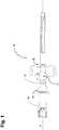
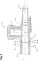
Fig. 1 is a top view of the intravenous catheter apparatus according to the present invention.Fig. 2 is a cross-sectional side view of the two parts forming a catheter hub according to the present invention.Fig. 3 is a cross-sectional side view of the two parts being joined together forming the catheter hub with a needle guard according to the present invention.- Embodiments of the presently disclosed invention will now be described in detail with reference to the drawings wherein like reference numerals designate identical or corresponding elements. In the drawings and in the description, the term "proximal" refers to a region of the device or parts thereof or a location on the device which is closest to, for example, a user using the device. In contrast to this, the term "distal" refers to a region of the device which is farthest from the user, for example, the distal region of a needle will be the region of the needle containing the needle tip which is to be inserted e.g. into a patient's vein.
- Referring to
Figs. 1-3 anintravenous catheter apparatus 10 in accordance with the invention is illustrated. Theintravenous catheter apparatus 10 includes acatheter hub 12 having afluid path 11, acatheter tube 14 and a needle 20. Thecatheter hub 12 has adistal end 22 and aproximal end 24, wherein thecatheter tube 14 is arranged adjacent to thedistal end 22 of thecatheter hub 12. The needle 20 has a needle shaft 28, a needle tip at a distal section of the needle shaft 28 and aneedle hub 16 attached to aproximal section 36 of the needle shaft 28. An enlargement (not shown) of the needle 20 is provided between the distal section and theproximal section 36 of the needle shaft 28. The enlargement has a maximum dimension in a direction transverse to the needle shaft 28, which is greater than the outer diameter of the distal orproximal section 36. The enlargement can be made, for example, by crimping the needle shaft 28. - Prior to use of the
catheter apparatus 10, the needle 20 is received in thecatheter hub 12 andcatheter tube 14, such that the needle shaft 28 extends through the length of thecatheter tube 14. Aneedle guard 26 is movably arranged on the needle shaft 28 and retained in thecatheter hub 12 prior to use of thecatheter apparatus 10 as shown inFig. 3 . Theneedle guard 26 has abase portion 44, afirst arm 40, asecond arm 42 and adistal wall 18. Thedistal wall 18 is arranged at a distal end of thefirst arm 40 and extends in a direction transverse to an axial direction A of the needle 20. Atension element 46, for example, a rubber band or the like, surrounds the first andsecond arms second arms needle guard 26 extend generally in the axial direction A from adistal side 60 of thebase portion 44, i.e. generally parallel to the needle shaft 28. - In one of the preferred embodiments, upon withdrawal of the needle 20 from the
catheter tube 14 andcatheter hub 12 the needle shaft 28 moves relative to theneedle guard 26 until the needle tip is received in theneedle guard 26. Once the needle tip is received in theneedle guard 26 the enlargement of the needle shaft 28 engages with thebase portion 44 of theneedle guard 26 via a stoppingelement 38 such that theneedle guard 26 can be pulled out of thecatheter hub 12 together with the needle 20. An axial movement of the needle 20 relative to theneedle guard 26 is now limited, as thedistal wall 18 blocks the needle tip axially and the engagement between the enlargement and thebase portion 44 via the stoppingelement 38 prevents the needle tip from being removed via thebase portion 44, i.e. the needle tip is safely surrounded by theneedle guard 26. - Referring now to
Fig. 2 , thecatheter hub 12 is made of two parts, i.e. afirst part 12a and asecond part 12b comprising thefluid path 11. Thefirst part 12a has adistal end section 50 and thesecond part 12b has aproximal end section 52. Thefirst part 12a is part of ahousing 48 to receive aneedle guard 26 which is movably arranged on the needle shaft 28 of the needle 20. Thedistal end 22 of thesecond part 12b is connected to acatheter tube 14. - The
distal end section 50 of thefirst part 12a is configured to be assembled with theproximal end section 52 of thesecond part 12b in various ways in a fluid tight manner, such as by adhesive sealing, ultrasonic welding, heated die, radio frequency sealing, mechanical seal (snap fit), insert molding, laser welding etc., ensuring a leak free joint. It is also possible to join the twoparts Figs. 2 and3 , the first andsecond parts - As illustrated in
Figs. 2 and3 , thehousing 48 is defined by the first andsecond parts catheter hub 12 that houses theneedle guard 26 and is configured such that it defines achamber 54 at one end of thesecond part 12b. Thechamber 54 is configured to provide room/space for theneedle guard 26 in its ready position. Thechamber 54 is formed by an indentation in thehousing 48 for accommodating the first andsecond arms arms inner surface 56 of thechamber 54. In this embodiment, thechamber 54 is arranged in theproximal end section 52 of thesecond part 12b and defined by the first andsecond parts surface areas parts - In this ready position, the
first arm 40 deflects outward of theneedle guard 26 such that thedistal wall 18 of thefirst arm 40 is supported on the needle shaft 28. Further, in this ready position, the first andsecond arms surface 56 of thechamber 54 prior and during venipuncture of a patient. Theinner surface 56 is parallel to the axial direction A and defined only by thesecond part 12b. This non-contact of the first andsecond arms inner surface 56 of thechamber 54 significantly decreases the withdrawal force required and friction caused when a needle 20 is withdrawn through acatheter hub 12 being protected by aneedle guard 26 after use. Moreover, thefirst part 12a comprises asurface 58 which is inclined towards the inside of thehousing 48 in a proximal direction of thecatheter hub 12. Thischamfered surface 58 forms a radial shoulder and serves as an axial stop in the proximal direction of thecatheter hub 12 for thearms surface 58 has a smaller inside diameter at its innermost end than a distance between outermost points of thearms chamber 54. In other words, thearms surface 58 in the ready position, as shown inFig. 3 . However, in this retracted position, thearms surface 58. - As shown in
Figs. 2 and3 , prior to the use of theintravenous catheter apparatus 10, theneedle guard 26 is arranged in thecatheter hub 12 near aproximal end 24 of the needle shaft 28. In this situation, the needle 20 extends completely through theneedle guard 26, thereby deflecting thefirst arm 40 of theneedle guard 26 outwards, i.e. at an angle to the axial direction A, such that thedistal wall 18 of thefirst arm 40 is supported on the needle shaft 28. Following the insertion of thecatheter tube 14 into a patient, the needle 20 is withdrawn from thecatheter tube 14 and the needle shaft 28 moves through theneedle guard 26 while theneedle guard 26 is retained in thecatheter hub 12. Once the needle tip passes the transversedistal wall 18 of theneedle guard 26, while being retracted, such that the needle shaft 28 no longer supports thedistal wall 18, a restoring force of thetension element 46 and the first arm's 40 inherent elasticity ensure that thefirst arm 40 of theneedle guard 26 is moved back into alignment with the axial direction A, so that the needle tip is blocked by being axially covered by thedistal wall 18 of theneedle guard 26, i.e. the needle tip is prevented from axially projecting out of theneedle guard 26. - The
catheter apparatus 10 is particularly inexpensive to manufacture if thebase portion 44, the first andsecond arms base portion 44, the first andsecond arms - Alternatively, the
base portion 44, and one of the first andsecond arms second arms second arms - The construction and shape of the improved
intravenous catheter apparatus 10 of the present disclosure provides a simple configuration. The simple design of theintravenous catheter apparatus 10 is advantageous in a clinical setting because it smoothens the whole catheterization process thereby reducing injury or discomfort to a patient. In addition, such design greatly reduces manufacturing costs and is efficient, effective and simple in its construction and use. - Although this invention has been disclosed in the context of certain preferred embodiments and examples, it will be understood by those skilled in the art that the present invention extends beyond the specifically disclosed embodiments to other alternative embodiments and obvious modifications thereof. Thus, from the foregoing description, it will be apparent to one of ordinary skill in the art that many changes and modifications can be made thereto without departing from the scope of the invention as set forth in the claims. Accordingly, it is not intended that the scope of the foregoing description be limited to the exact description set forth above, but rather that such description be construed as encompassing such features that reside in the present invention. The scope of the present invention herein disclosed is not limited by the particular disclosed embodiments described above but determined only by a fair reading of the appended claims.
- 10
- intravenous catheter apparatus
- 11
- fluid path
- 12
- catheter hub
- 12a
- first part of catheter hub
- 12b
- second part of catheter hub
- 14
- catheter tube
- 16
- needle hub
- 18
- distal wall
- 20
- needle
- 22
- distal end
- 24
- proximal end
- 26
- needle guard
- 28
- needle shaft
- 36
- proximal section
- 38
- stopping element
- 40
- first arm
- 42
- second arm
- 44
- base portion
- 46
- tension element
- 48
- housing
- 50
- distal end section
- 52
- proximal end section
- 54
- chamber
- 56
- inner surface/wall
- 57
- stepped surface of
part 12a - 58
- inclined inner surface
- 59
- stepped surface of
part 12b - 60
- distal side
- A
- axial direction
Claims (8)
- An intravenous catheter apparatus (10) comprising:a catheter tube (14);a catheter hub (12) having a distal end (22) and a proximal end (24), wherein the distal end (22) is joined to the catheter tube (14) and the proximal end (24) defines a housing (48);a needle (20) extending through the catheter hub (12) and the catheter tube (14) and defining an axial direction (A), wherein the needle (20) has opposite proximal and distal ends, the distal end forming a needle tip;a needle hub (16) attached to the proximal end of the needle (20);a needle guard (26) slidably arranged on the needle (20), wherein the needle guard (26) is movably retained in the housing (48) of the catheter hub (12), when the needle (20) extends through the catheter hub (12) and the catheter tube (14), wherein the needle guard (26) is removable from the catheter hub (12) once the needle tip is received in the needle guard (26) upon withdrawal of the needle (20) from the catheter tube (14), and wherein the housing (48) defines a chamber (54) at one end thereof ensuring that a first and second arm (40, 42) of the needle guard (26) do not engage or interact with an inner surface (56) of the chamber (54) prior and during venipuncture of a patientthe chamber (54) is formed by an indentation in the housing (48) for accommodating the first and second arm (40, 42) such that none of the arms (40, 42) deflected by the needle (20) contact the inner surface (56) of the chamber (54),characterised in that the catheter hub (12) is made of two parts, a proximal part (12a) with a distal end section (50) and a distal part (12b) with a proximal end section (52), wherein the Inner surface (56) of the chamber (54) is defined by the proximal end section (52) of the distal part (12b).
- The intravenous catheter apparatus (10) as claimed in claim 1, wherein the proximal and distal parts (12a, 12b) define the housing (48) to receive the needle guard (26) which is movably arranged on the needle (20).
- The intravenous catheter apparatus (10) as claimed In claim 1 or 2, wherein a distal end section (50) of the proximal part (12a) is joined with a proximal end section (52) of the distal part (12b) in a fluid tight manner.
- The intravenous catheter apparatus (10) as claimed In any one of claims 1 to 3, wherein the proximal and distal parts (12a, 12b) are joined by complementary end portions (57, 59).
- The intravenous catheter apparatus (10) as claimed in claim 4, wherein the end portions (57, 59) are stepped.
- The Intravenous catheter apparatus (10) as claimed in any one of claims 1 to 5, wherein the proximal and distal parts (12a, 12b) form the chamber (54).
- The intravenous catheter apparatus (10) as claimed in claim 6, wherein the inner surface (56) of the chamber (54) is parallel to the axial direction (A) and defined only by the distal part (12b).
- The intravenous catheter apparatus (10) as claimed in claim 7, wherein the proximal part (12a) comprises a surface (58) joined with the inner surface (56) of the distal part (12b), which surface (58) is inclined towards the inside of the housing (48) in a proximal direction of the catheter hub (12), wherein the surface (58) has a smaller inside diameter at its innermost end than a distance between outermost points of the arms (40, 42) in their deflected state inside the chamber (54).
Applications Claiming Priority (2)
| Application Number | Priority Date | Filing Date | Title |
|---|---|---|---|
| IN1916DE2015 | 2015-06-27 | ||
| PCT/IB2016/050536WO2017001942A1 (en) | 2015-06-27 | 2016-02-03 | Intravenous catheter apparatus |
Publications (2)
| Publication Number | Publication Date |
|---|---|
| EP3131614A1 EP3131614A1 (en) | 2017-02-22 |
| EP3131614B1true EP3131614B1 (en) | 2018-08-22 |
Family
ID=55521756
Family Applications (1)
| Application Number | Title | Priority Date | Filing Date |
|---|---|---|---|
| EP16705703.3AActiveEP3131614B1 (en) | 2015-06-27 | 2016-02-03 | Intravenous catheter apparatus |
Country Status (4)
| Country | Link |
|---|---|
| US (1) | US10335579B2 (en) |
| EP (1) | EP3131614B1 (en) |
| ES (1) | ES2689910T3 (en) |
| WO (1) | WO2017001942A1 (en) |
Families Citing this family (2)
| Publication number | Priority date | Publication date | Assignee | Title |
|---|---|---|---|---|
| EP3919110B1 (en) | 2017-03-24 | 2024-11-20 | Poly Medicure Limited | A fluid administration medical apparatus |
| EP3630257A4 (en) | 2017-05-26 | 2021-03-17 | Piper Access, LLC | Catheter delivery devices, systems, and methods |
Family Cites Families (9)
| Publication number | Priority date | Publication date | Assignee | Title |
|---|---|---|---|---|
| US8382721B2 (en)* | 1997-08-20 | 2013-02-26 | B. Braun Melsungen Ag | Spring clip safety IV catheter |
| DE20210394U1 (en)* | 2002-07-04 | 2002-09-12 | B. Braun Melsungen Ag, 34212 Melsungen | catheter introducer |
| EP1803477A3 (en)* | 2004-02-13 | 2007-07-18 | Smiths Medical ASD, Inc. | Catheter with needle tip protector |
| US8992483B2 (en)* | 2007-03-27 | 2015-03-31 | Nipro Corporation | Indwelling needle assembly and protector |
| US7828774B2 (en)* | 2008-05-12 | 2010-11-09 | Harding Weston F | Sleeved clip safety |
| US8398597B2 (en)* | 2008-06-17 | 2013-03-19 | Becton, Dickinson And Company | Needle shield and interlock |
| MX2014015901A (en)* | 2012-06-19 | 2015-03-03 | Poly Medicure Ltd | Needle guard. |
| US10918837B2 (en)* | 2013-12-04 | 2021-02-16 | B. Braun Melsungen Ag | Safety needle assemblies and related methods |
| SG10201809504QA (en)* | 2014-04-29 | 2018-11-29 | Braun Melsungen Ag | Valved catheter assemblies and related methods |
- 2016
- 2016-02-03EPEP16705703.3Apatent/EP3131614B1/enactiveActive
- 2016-02-03WOPCT/IB2016/050536patent/WO2017001942A1/ennot_activeCeased
- 2016-02-03USUS15/022,458patent/US10335579B2/enactiveActive
- 2016-02-03ESES16705703.3Tpatent/ES2689910T3/enactiveActive
Non-Patent Citations (1)
| Title |
|---|
| None* |
Also Published As
| Publication number | Publication date |
|---|---|
| US20170197062A1 (en) | 2017-07-13 |
| WO2017001942A1 (en) | 2017-01-05 |
| US10335579B2 (en) | 2019-07-02 |
| EP3131614A1 (en) | 2017-02-22 |
| ES2689910T3 (en) | 2018-11-16 |
Similar Documents
| Publication | Publication Date | Title |
|---|---|---|
| EP3135333B1 (en) | Intravenous catheter apparatus | |
| US10729889B2 (en) | Needle devices with dual diameter cannula and related methods | |
| KR101707008B1 (en) | Catheter apparatus | |
| JP6925319B2 (en) | Catheter devices with valves and related methods | |
| EP2498841B1 (en) | Iv-catheter insertion device | |
| US9687633B2 (en) | Safety needle devices and related methods | |
| EP2817060B1 (en) | Catheter apparatus | |
| EP2735330B1 (en) | An improved needle tip guard | |
| EP2566543B1 (en) | Needle safety device for medical devices | |
| EP3131614B1 (en) | Intravenous catheter apparatus | |
| JP7512300B2 (en) | Intravenous Catheter Device | |
| HK40033690B (en) | Needle safety device and assembly | |
| HK40033690A (en) | Needle safety device and assembly | |
| HK1255008B (en) | Needle devices with dual diameter cannula and related methods | |
| HK1239576A1 (en) | Needle safety device and assembly | |
| HK1184087A (en) | Needle safety device and assembly |
Legal Events
| Date | Code | Title | Description |
|---|---|---|---|
| STAA | Information on the status of an ep patent application or granted ep patent | Free format text:STATUS: THE INTERNATIONAL PUBLICATION HAS BEEN MADE | |
| PUAI | Public reference made under article 153(3) epc to a published international application that has entered the european phase | Free format text:ORIGINAL CODE: 0009012 | |
| STAA | Information on the status of an ep patent application or granted ep patent | Free format text:STATUS: REQUEST FOR EXAMINATION WAS MADE | |
| 17P | Request for examination filed | Effective date:20160307 | |
| AK | Designated contracting states | Kind code of ref document:A1 Designated state(s):AL AT BE BG CH CY CZ DE DK EE ES FI FR GB GR HR HU IE IS IT LI LT LU LV MC MK MT NL NO PL PT RO RS SE SI SK SM TR | |
| AX | Request for extension of the european patent | Extension state:BA ME | |
| STAA | Information on the status of an ep patent application or granted ep patent | Free format text:STATUS: EXAMINATION IS IN PROGRESS | |
| 17Q | First examination report despatched | Effective date:20170518 | |
| GRAP | Despatch of communication of intention to grant a patent | Free format text:ORIGINAL CODE: EPIDOSNIGR1 | |
| STAA | Information on the status of an ep patent application or granted ep patent | Free format text:STATUS: GRANT OF PATENT IS INTENDED | |
| GRAJ | Information related to disapproval of communication of intention to grant by the applicant or resumption of examination proceedings by the epo deleted | Free format text:ORIGINAL CODE: EPIDOSDIGR1 | |
| STAA | Information on the status of an ep patent application or granted ep patent | Free format text:STATUS: EXAMINATION IS IN PROGRESS | |
| DAV | Request for validation of the european patent (deleted) | ||
| DAX | Request for extension of the european patent (deleted) | ||
| INTG | Intention to grant announced | Effective date:20180105 | |
| INTC | Intention to grant announced (deleted) | ||
| GRAP | Despatch of communication of intention to grant a patent | Free format text:ORIGINAL CODE: EPIDOSNIGR1 | |
| STAA | Information on the status of an ep patent application or granted ep patent | Free format text:STATUS: GRANT OF PATENT IS INTENDED | |
| INTG | Intention to grant announced | Effective date:20180314 | |
| GRAS | Grant fee paid | Free format text:ORIGINAL CODE: EPIDOSNIGR3 | |
| GRAA | (expected) grant | Free format text:ORIGINAL CODE: 0009210 | |
| STAA | Information on the status of an ep patent application or granted ep patent | Free format text:STATUS: THE PATENT HAS BEEN GRANTED | |
| AK | Designated contracting states | Kind code of ref document:B1 Designated state(s):AL AT BE BG CH CY CZ DE DK EE ES FI FR GB GR HR HU IE IS IT LI LT LU LV MC MK MT NL NO PL PT RO RS SE SI SK SM TR | |
| REG | Reference to a national code | Ref country code:GB Ref legal event code:FG4D | |
| REG | Reference to a national code | Ref country code:CH Ref legal event code:EP | |
| REG | Reference to a national code | Ref country code:AT Ref legal event code:REF Ref document number:1031752 Country of ref document:AT Kind code of ref document:T Effective date:20180915 | |
| REG | Reference to a national code | Ref country code:IE Ref legal event code:FG4D | |
| REG | Reference to a national code | Ref country code:DE Ref legal event code:R096 Ref document number:602016005014 Country of ref document:DE | |
| REG | Reference to a national code | Ref country code:ES Ref legal event code:FG2A Ref document number:2689910 Country of ref document:ES Kind code of ref document:T3 Effective date:20181116 | |
| REG | Reference to a national code | Ref country code:NL Ref legal event code:MP Effective date:20180822 | |
| REG | Reference to a national code | Ref country code:LT Ref legal event code:MG4D | |
| PG25 | Lapsed in a contracting state [announced via postgrant information from national office to epo] | Ref country code:FI Free format text:LAPSE BECAUSE OF FAILURE TO SUBMIT A TRANSLATION OF THE DESCRIPTION OR TO PAY THE FEE WITHIN THE PRESCRIBED TIME-LIMIT Effective date:20180822 Ref country code:GR Free format text:LAPSE BECAUSE OF FAILURE TO SUBMIT A TRANSLATION OF THE DESCRIPTION OR TO PAY THE FEE WITHIN THE PRESCRIBED TIME-LIMIT Effective date:20181123 Ref country code:RS Free format text:LAPSE BECAUSE OF FAILURE TO SUBMIT A TRANSLATION OF THE DESCRIPTION OR TO PAY THE FEE WITHIN THE PRESCRIBED TIME-LIMIT Effective date:20180822 Ref country code:IS Free format text:LAPSE BECAUSE OF FAILURE TO SUBMIT A TRANSLATION OF THE DESCRIPTION OR TO PAY THE FEE WITHIN THE PRESCRIBED TIME-LIMIT Effective date:20181222 Ref country code:NO Free format text:LAPSE BECAUSE OF FAILURE TO SUBMIT A TRANSLATION OF THE DESCRIPTION OR TO PAY THE FEE WITHIN THE PRESCRIBED TIME-LIMIT Effective date:20181122 Ref country code:NL Free format text:LAPSE BECAUSE OF FAILURE TO SUBMIT A TRANSLATION OF THE DESCRIPTION OR TO PAY THE FEE WITHIN THE PRESCRIBED TIME-LIMIT Effective date:20180822 Ref country code:BG Free format text:LAPSE BECAUSE OF FAILURE TO SUBMIT A TRANSLATION OF THE DESCRIPTION OR TO PAY THE FEE WITHIN THE PRESCRIBED TIME-LIMIT Effective date:20181122 Ref country code:SE Free format text:LAPSE BECAUSE OF FAILURE TO SUBMIT A TRANSLATION OF THE DESCRIPTION OR TO PAY THE FEE WITHIN THE PRESCRIBED TIME-LIMIT Effective date:20180822 Ref country code:LT Free format text:LAPSE BECAUSE OF FAILURE TO SUBMIT A TRANSLATION OF THE DESCRIPTION OR TO PAY THE FEE WITHIN THE PRESCRIBED TIME-LIMIT Effective date:20180822 | |
| REG | Reference to a national code | Ref country code:AT Ref legal event code:MK05 Ref document number:1031752 Country of ref document:AT Kind code of ref document:T Effective date:20180822 | |
| PG25 | Lapsed in a contracting state [announced via postgrant information from national office to epo] | Ref country code:AL Free format text:LAPSE BECAUSE OF FAILURE TO SUBMIT A TRANSLATION OF THE DESCRIPTION OR TO PAY THE FEE WITHIN THE PRESCRIBED TIME-LIMIT Effective date:20180822 Ref country code:LV Free format text:LAPSE BECAUSE OF FAILURE TO SUBMIT A TRANSLATION OF THE DESCRIPTION OR TO PAY THE FEE WITHIN THE PRESCRIBED TIME-LIMIT Effective date:20180822 Ref country code:HR Free format text:LAPSE BECAUSE OF FAILURE TO SUBMIT A TRANSLATION OF THE DESCRIPTION OR TO PAY THE FEE WITHIN THE PRESCRIBED TIME-LIMIT Effective date:20180822 | |
| PG25 | Lapsed in a contracting state [announced via postgrant information from national office to epo] | Ref country code:PL Free format text:LAPSE BECAUSE OF FAILURE TO SUBMIT A TRANSLATION OF THE DESCRIPTION OR TO PAY THE FEE WITHIN THE PRESCRIBED TIME-LIMIT Effective date:20180822 Ref country code:RO Free format text:LAPSE BECAUSE OF FAILURE TO SUBMIT A TRANSLATION OF THE DESCRIPTION OR TO PAY THE FEE WITHIN THE PRESCRIBED TIME-LIMIT Effective date:20180822 Ref country code:CZ Free format text:LAPSE BECAUSE OF FAILURE TO SUBMIT A TRANSLATION OF THE DESCRIPTION OR TO PAY THE FEE WITHIN THE PRESCRIBED TIME-LIMIT Effective date:20180822 Ref country code:AT Free format text:LAPSE BECAUSE OF FAILURE TO SUBMIT A TRANSLATION OF THE DESCRIPTION OR TO PAY THE FEE WITHIN THE PRESCRIBED TIME-LIMIT Effective date:20180822 Ref country code:EE Free format text:LAPSE BECAUSE OF FAILURE TO SUBMIT A TRANSLATION OF THE DESCRIPTION OR TO PAY THE FEE WITHIN THE PRESCRIBED TIME-LIMIT Effective date:20180822 | |
| REG | Reference to a national code | Ref country code:DE Ref legal event code:R097 Ref document number:602016005014 Country of ref document:DE | |
| PG25 | Lapsed in a contracting state [announced via postgrant information from national office to epo] | Ref country code:DK Free format text:LAPSE BECAUSE OF FAILURE TO SUBMIT A TRANSLATION OF THE DESCRIPTION OR TO PAY THE FEE WITHIN THE PRESCRIBED TIME-LIMIT Effective date:20180822 Ref country code:SM Free format text:LAPSE BECAUSE OF FAILURE TO SUBMIT A TRANSLATION OF THE DESCRIPTION OR TO PAY THE FEE WITHIN THE PRESCRIBED TIME-LIMIT Effective date:20180822 Ref country code:SK Free format text:LAPSE BECAUSE OF FAILURE TO SUBMIT A TRANSLATION OF THE DESCRIPTION OR TO PAY THE FEE WITHIN THE PRESCRIBED TIME-LIMIT Effective date:20180822 | |
| PLBE | No opposition filed within time limit | Free format text:ORIGINAL CODE: 0009261 | |
| STAA | Information on the status of an ep patent application or granted ep patent | Free format text:STATUS: NO OPPOSITION FILED WITHIN TIME LIMIT | |
| 26N | No opposition filed | Effective date:20190523 | |
| PG25 | Lapsed in a contracting state [announced via postgrant information from national office to epo] | Ref country code:SI Free format text:LAPSE BECAUSE OF FAILURE TO SUBMIT A TRANSLATION OF THE DESCRIPTION OR TO PAY THE FEE WITHIN THE PRESCRIBED TIME-LIMIT Effective date:20180822 | |
| PG25 | Lapsed in a contracting state [announced via postgrant information from national office to epo] | Ref country code:TR Free format text:LAPSE BECAUSE OF FAILURE TO SUBMIT A TRANSLATION OF THE DESCRIPTION OR TO PAY THE FEE WITHIN THE PRESCRIBED TIME-LIMIT Effective date:20180822 | |
| PG25 | Lapsed in a contracting state [announced via postgrant information from national office to epo] | Ref country code:MT Free format text:LAPSE BECAUSE OF NON-PAYMENT OF DUE FEES Effective date:20190203 Ref country code:PT Free format text:LAPSE BECAUSE OF FAILURE TO SUBMIT A TRANSLATION OF THE DESCRIPTION OR TO PAY THE FEE WITHIN THE PRESCRIBED TIME-LIMIT Effective date:20181222 | |
| PGFP | Annual fee paid to national office [announced via postgrant information from national office to epo] | Ref country code:IE Payment date:20210216 Year of fee payment:6 Ref country code:CH Payment date:20210216 Year of fee payment:6 Ref country code:MC Payment date:20210217 Year of fee payment:6 Ref country code:LU Payment date:20210218 Year of fee payment:6 | |
| PG25 | Lapsed in a contracting state [announced via postgrant information from national office to epo] | Ref country code:CY Free format text:LAPSE BECAUSE OF FAILURE TO SUBMIT A TRANSLATION OF THE DESCRIPTION OR TO PAY THE FEE WITHIN THE PRESCRIBED TIME-LIMIT Effective date:20180822 | |
| PGFP | Annual fee paid to national office [announced via postgrant information from national office to epo] | Ref country code:BE Payment date:20210218 Year of fee payment:6 | |
| PG25 | Lapsed in a contracting state [announced via postgrant information from national office to epo] | Ref country code:HU Free format text:LAPSE BECAUSE OF FAILURE TO SUBMIT A TRANSLATION OF THE DESCRIPTION OR TO PAY THE FEE WITHIN THE PRESCRIBED TIME-LIMIT; INVALID AB INITIO Effective date:20160203 | |
| REG | Reference to a national code | Ref country code:DE Ref legal event code:R082 Ref document number:602016005014 Country of ref document:DE Representative=s name:THUM, MOETSCH, WEICKERT PATENTANWAELTE PARTG M, DE Ref country code:DE Ref legal event code:R082 Ref document number:602016005014 Country of ref document:DE Representative=s name:THUM & PARTNER THUM MOETSCH WEICKERT PATENTANW, DE | |
| PG25 | Lapsed in a contracting state [announced via postgrant information from national office to epo] | Ref country code:MK Free format text:LAPSE BECAUSE OF FAILURE TO SUBMIT A TRANSLATION OF THE DESCRIPTION OR TO PAY THE FEE WITHIN THE PRESCRIBED TIME-LIMIT Effective date:20180822 | |
| PG25 | Lapsed in a contracting state [announced via postgrant information from national office to epo] | Ref country code:MC Free format text:LAPSE BECAUSE OF NON-PAYMENT OF DUE FEES Effective date:20220228 | |
| REG | Reference to a national code | Ref country code:CH Ref legal event code:PL | |
| REG | Reference to a national code | Ref country code:BE Ref legal event code:MM Effective date:20220228 | |
| PG25 | Lapsed in a contracting state [announced via postgrant information from national office to epo] | Ref country code:LU Free format text:LAPSE BECAUSE OF NON-PAYMENT OF DUE FEES Effective date:20220203 | |
| PG25 | Lapsed in a contracting state [announced via postgrant information from national office to epo] | Ref country code:LI Free format text:LAPSE BECAUSE OF NON-PAYMENT OF DUE FEES Effective date:20220228 Ref country code:IE Free format text:LAPSE BECAUSE OF NON-PAYMENT OF DUE FEES Effective date:20220203 Ref country code:CH Free format text:LAPSE BECAUSE OF NON-PAYMENT OF DUE FEES Effective date:20220228 | |
| PG25 | Lapsed in a contracting state [announced via postgrant information from national office to epo] | Ref country code:BE Free format text:LAPSE BECAUSE OF NON-PAYMENT OF DUE FEES Effective date:20220228 | |
| P01 | Opt-out of the competence of the unified patent court (upc) registered | Effective date:20230524 | |
| PGFP | Annual fee paid to national office [announced via postgrant information from national office to epo] | Ref country code:DE Payment date:20250218 Year of fee payment:10 | |
| PGFP | Annual fee paid to national office [announced via postgrant information from national office to epo] | Ref country code:ES Payment date:20250318 Year of fee payment:10 | |
| PGFP | Annual fee paid to national office [announced via postgrant information from national office to epo] | Ref country code:FR Payment date:20250220 Year of fee payment:10 | |
| PGFP | Annual fee paid to national office [announced via postgrant information from national office to epo] | Ref country code:IT Payment date:20250228 Year of fee payment:10 Ref country code:GB Payment date:20250220 Year of fee payment:10 |