EP3131358B1 - Control signaling for transmissions over contiguous and non-contiguous frequency bands - Google Patents
Control signaling for transmissions over contiguous and non-contiguous frequency bandsDownload PDFInfo
- Publication number
- EP3131358B1 EP3131358B1EP16190949.4AEP16190949AEP3131358B1EP 3131358 B1EP3131358 B1EP 3131358B1EP 16190949 AEP16190949 AEP 16190949AEP 3131358 B1EP3131358 B1EP 3131358B1
- Authority
- EP
- European Patent Office
- Prior art keywords
- resource
- resource allocation
- clusters
- contiguous
- cluster
- Prior art date
- Legal status (The legal status is an assumption and is not a legal conclusion. Google has not performed a legal analysis and makes no representation as to the accuracy of the status listed.)
- Active
Links
Images


Classifications
- H—ELECTRICITY
- H04—ELECTRIC COMMUNICATION TECHNIQUE
- H04W—WIRELESS COMMUNICATION NETWORKS
- H04W72/00—Local resource management
- H04W72/12—Wireless traffic scheduling
- H04W72/1263—Mapping of traffic onto schedule, e.g. scheduled allocation or multiplexing of flows
- H04W72/1268—Mapping of traffic onto schedule, e.g. scheduled allocation or multiplexing of flows of uplink data flows
- H—ELECTRICITY
- H04—ELECTRIC COMMUNICATION TECHNIQUE
- H04B—TRANSMISSION
- H04B1/00—Details of transmission systems, not covered by a single one of groups H04B3/00 - H04B13/00; Details of transmission systems not characterised by the medium used for transmission
- H04B1/69—Spread spectrum techniques
- H04B1/713—Spread spectrum techniques using frequency hopping
- H—ELECTRICITY
- H04—ELECTRIC COMMUNICATION TECHNIQUE
- H04L—TRANSMISSION OF DIGITAL INFORMATION, e.g. TELEGRAPHIC COMMUNICATION
- H04L1/00—Arrangements for detecting or preventing errors in the information received
- H04L1/12—Arrangements for detecting or preventing errors in the information received by using return channel
- H04L1/16—Arrangements for detecting or preventing errors in the information received by using return channel in which the return channel carries supervisory signals, e.g. repetition request signals
- H04L1/18—Automatic repetition systems, e.g. Van Duuren systems
- H04L1/1812—Hybrid protocols; Hybrid automatic repeat request [HARQ]
- H—ELECTRICITY
- H04—ELECTRIC COMMUNICATION TECHNIQUE
- H04L—TRANSMISSION OF DIGITAL INFORMATION, e.g. TELEGRAPHIC COMMUNICATION
- H04L1/00—Arrangements for detecting or preventing errors in the information received
- H04L1/12—Arrangements for detecting or preventing errors in the information received by using return channel
- H04L1/16—Arrangements for detecting or preventing errors in the information received by using return channel in which the return channel carries supervisory signals, e.g. repetition request signals
- H04L1/18—Automatic repetition systems, e.g. Van Duuren systems
- H04L1/1867—Arrangements specially adapted for the transmitter end
- H04L1/1893—Physical mapping arrangements
- H—ELECTRICITY
- H04—ELECTRIC COMMUNICATION TECHNIQUE
- H04L—TRANSMISSION OF DIGITAL INFORMATION, e.g. TELEGRAPHIC COMMUNICATION
- H04L5/00—Arrangements affording multiple use of the transmission path
- H—ELECTRICITY
- H04—ELECTRIC COMMUNICATION TECHNIQUE
- H04L—TRANSMISSION OF DIGITAL INFORMATION, e.g. TELEGRAPHIC COMMUNICATION
- H04L5/00—Arrangements affording multiple use of the transmission path
- H04L5/0001—Arrangements for dividing the transmission path
- H04L5/0003—Two-dimensional division
- H04L5/0005—Time-frequency
- H04L5/0007—Time-frequency the frequencies being orthogonal, e.g. OFDM(A) or DMT
- H04L5/0012—Hopping in multicarrier systems
- H—ELECTRICITY
- H04—ELECTRIC COMMUNICATION TECHNIQUE
- H04L—TRANSMISSION OF DIGITAL INFORMATION, e.g. TELEGRAPHIC COMMUNICATION
- H04L5/00—Arrangements affording multiple use of the transmission path
- H04L5/0001—Arrangements for dividing the transmission path
- H04L5/0014—Three-dimensional division
- H04L5/0023—Time-frequency-space
- H—ELECTRICITY
- H04—ELECTRIC COMMUNICATION TECHNIQUE
- H04L—TRANSMISSION OF DIGITAL INFORMATION, e.g. TELEGRAPHIC COMMUNICATION
- H04L5/00—Arrangements affording multiple use of the transmission path
- H04L5/003—Arrangements for allocating sub-channels of the transmission path
- H04L5/0044—Allocation of payload; Allocation of data channels, e.g. PDSCH or PUSCH
- H04L5/0046—Determination of the number of bits transmitted on different sub-channels
- H—ELECTRICITY
- H04—ELECTRIC COMMUNICATION TECHNIQUE
- H04L—TRANSMISSION OF DIGITAL INFORMATION, e.g. TELEGRAPHIC COMMUNICATION
- H04L5/00—Arrangements affording multiple use of the transmission path
- H04L5/003—Arrangements for allocating sub-channels of the transmission path
- H04L5/0048—Allocation of pilot signals, i.e. of signals known to the receiver
- H—ELECTRICITY
- H04—ELECTRIC COMMUNICATION TECHNIQUE
- H04L—TRANSMISSION OF DIGITAL INFORMATION, e.g. TELEGRAPHIC COMMUNICATION
- H04L5/00—Arrangements affording multiple use of the transmission path
- H04L5/003—Arrangements for allocating sub-channels of the transmission path
- H04L5/0053—Allocation of signalling, i.e. of overhead other than pilot signals
- H—ELECTRICITY
- H04—ELECTRIC COMMUNICATION TECHNIQUE
- H04W—WIRELESS COMMUNICATION NETWORKS
- H04W72/00—Local resource management
- H04W72/04—Wireless resource allocation
- H04W72/044—Wireless resource allocation based on the type of the allocated resource
- H04W72/0453—Resources in frequency domain, e.g. a carrier in FDMA
- H—ELECTRICITY
- H04—ELECTRIC COMMUNICATION TECHNIQUE
- H04W—WIRELESS COMMUNICATION NETWORKS
- H04W72/00—Local resource management
- H04W72/12—Wireless traffic scheduling
- H—ELECTRICITY
- H04—ELECTRIC COMMUNICATION TECHNIQUE
- H04W—WIRELESS COMMUNICATION NETWORKS
- H04W72/00—Local resource management
- H04W72/20—Control channels or signalling for resource management
- H04W72/23—Control channels or signalling for resource management in the downlink direction of a wireless link, i.e. towards a terminal
- H04W72/232—Control channels or signalling for resource management in the downlink direction of a wireless link, i.e. towards a terminal the control data signalling from the physical layer, e.g. DCI signalling
- H—ELECTRICITY
- H04—ELECTRIC COMMUNICATION TECHNIQUE
- H04W—WIRELESS COMMUNICATION NETWORKS
- H04W72/00—Local resource management
- H04W72/20—Control channels or signalling for resource management
- H04W72/23—Control channels or signalling for resource management in the downlink direction of a wireless link, i.e. towards a terminal
Definitions
- the present inventionrelates generally to wireless communication systems and, more particularly, to a structure of scheduling assignments for the transmission of data signals.
- a communication systemconsists of a DownLink (DL), supporting the transmission of signals from a base station (Node B) to User Equipments (UEs), and an UpLink (UL), supporting the transmission of signals from UEs to the Node B.
- DLDownLink
- UEUser Equipment
- ULUpLink
- a UEalso commonly referred to as a terminal or a mobile station, may be fixed or mobile and may be a wireless device, a cellular phone, a personal computer device, etc.
- a Node Bis generally a fixed station and may also be referred to as a Base Transceiver System (BTS), an access point, or some other terminology.
- BTSBase Transceiver System
- the DL signalsconsist of data signals, carrying information content, control signals, and Reference Signals (RS), which are also known as pilot signals.
- the Node Bconveys DL data signals through a Physical Downlink Shared CHannel (PDSCH).
- the UEsconvey UL data signals through a Physical Uplink Shared CHannel (PUSCH).
- the DL control signalsmay be of a broadcast or a UE-specific nature. Broadcast control signals convey system information to all UEs. UE-specific control signals can be used, among other purposes, to provide, to UEs, Scheduling Assignments (SAs) for PDSCH reception (DL SAs) or PUSCH transmission (UL SAs). SAs are transmitted through a Physical Downlink Control CHannel (PDCCH).
- SAsScheduling Assignments
- DL SAsPDSCH reception
- UL SAsPUSCH transmission
- SAsare transmitted through a Physical Downlink Control CHannel (PDCCH).
- the PDCCHis usually a major part of the total DL overhead and directly impacts the achievable DL system throughput.
- One method for reducing the PDCCH overheadis to scale the PDCCH size according to its required resources during each Transmission Time Interval (TTI).
- TTITransmission Time Interval
- a Control Channel Format Indicator (CCFI) parameter transmitted through a Physical Control Format Indicator CHannel (PCFICH)indicates the number of Orthogonal Frequency Division Multiplexing (OFDM) symbols occupied by the PDCCH.
- OFDMOrthogonal Frequency Division Multiplexing
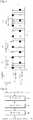
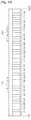
- FIG. 1A structure for the PDCCH and PDSCH transmission in the DL TTI is shown in FIG. 1 .
- the DL TTIis assumed to consist of a single sub-frame 110 having M OFDM symbols.
- a PDCCH 120occupies the first N OFDM symbols and a PDSCH 130 occupies the remaining M-N OFDM symbols.
- a PCFICH 140is transmitted in some sub-carriers, also referred to as Resource Elements (REs), of the first OFDM symbol.
- Some OFDM symbolsmay contain RS REs, 150 and 160, for each of the Node B transmitter antennas. In FIG. 1 , it is assumed that there are two Node B transmitter antennas.
- HARQHybrid Automatic Repeat reQuest
- PHICHPhysical Hybrid-HARQ Indicator CHannel
- the Node Bseparately encodes and transmits each of the UL SAs and DL SAs in the PDCCH.
- An SA encoding processis illustrated in FIG. 2 .
- the DL SA or UL SA information bits 210respectively conveying the information scheduling PDSCH reception or PUSCH transmission by a UE, are appended with Cyclic Redundancy Check (CRC) bits in step 220, and are subsequently encoded in step 230, for example using a convolutional code.
- CRCCyclic Redundancy Check
- the bitsare rate matched to the assigned PDCCH resources in step 240, and transmitted in step 250.
- each UEmay perform multiple decoding operations to determine whether it is assigned a DL SA or an UL SA in the corresponding sub-frame.
- the CRC of each SAis scrambled with an IDentity (ID) of the UE the SA is intended for.
- IDan IDentity
- a UEcan determine whether an SA is intended for the UE by performing a CRC check.
- the inverse operationsare performed to decode an SA as illustrated in FIG. 3 .
- the received SA 310is rate de-matched in step 320, decoded in step 330, and after the CRC is extracted in step 340, the SA information bits are obtained in step 350.
- the CRC checkpasses, the SA is considered to be intended for the UE.
- Single-Carrier Frequency Division Multiple Access(SC-FDMA) is assumed to be the transmission method.
- a sub-frame 410includes two slots.
- Each slot 420includes seven symbols used for the transmission of data or control signals.
- Each symbol 430further includes a Cyclic Prefix (CP) to mitigate interference due to channel propagation effects.
- PUSCH transmission in one slotmay be in the same or different part of the operating BandWidth (BW) than the PUSCH transmission in the other slot.
- PUSCH transmission in different BWs in each slotis referred to as Frequency Hopping (FH).
- FHFrequency Hopping
- the transmission BWis assumed to consist of frequency resource units, which are referred to as Physical Resource Blocks (PRBs).
- PRBsPhysical Resource Blocks
- Each PRBis further assumed to consist of N sc RB REs, and a UE is allocated M PUSCH consecutive PRBs 450 for its PUSCH transmission.
- a conventional UL SAis described through an set of Information Elements (IEs) in Table 1. Additional IEs or a different number of bits for the indicative IEs in Table 1 may apply.
- the order of the IEs in a UL SAcan be arbitrary.
- the length of the CRC (UE ID)is assumed to be 16 bits but other values, such as 20 bits or 24 bits, may be used instead.
- IEs of an UL SA for PUSCH Transmission in Contiguous PRBs InformationElement Number of Bits Comment Indication of UL SA 1 Indicates that the SA is for UL Transmission Resource Allocation (RA) 11 Assignment of Consecutive PRBs (total 50 PRBs) Modulation and Coding Scheme (MCS) 5 MCS Levels New Data Indicator (NDI) 1 New Data Indicator (synchronous HARQ) Transmission Power Control (TPC) 2 Power control commands Cyclic Shift Indicator (CSI) 3 SDMA (maximum of 8 UEs) Frequency Hopping (FH) 1 Frequency Hopping (Yes/No) Channel Quality Indicator (CQI) Request 1 Include CQI report (Yes/No) Unused Bit 1 To align the UL SA size with a DL SA size CRC (UE ID) 16 UE ID masked in the CRC TOTAL 42
- the first IEdifferentiates the UL SA from an SA used for a different purpose, such as, for example, for PDSCH scheduling (DL SA).
- the UL SA and the DL SAare desired to have the same size in order for both SAs to be examined with a single decoding operation at the UE.
- the second IEis a Resource Allocation (RA) IE, which specifies the assigned PRBs for PUSCH transmission.
- RAResource Allocation
- the number of required bitsis 11.
- the UL SAis assumed to contain an RA IE.
- the third IEindicates a Modulation and Coding Scheme (MCS) for the PUSCH transmission.
- MCSModulation and Coding Scheme
- the modulationmay be QPSK, QAM16, or QAM64, while the coding rate may take discrete values between, for example, 1/16 and 1.
- Some values of the MCS IEmay be reserved to be used in support of HARQ.
- the last 3 of the 32 MCS valuesmay be used to indicate a Redundancy Version (RV) for a packet retransmission for the same Transport Block (TB).
- RVRedundancy Version
- TBTransport Block
- the MCSis determined from the MCS of the previous SA for the same TB, which is assumed to be specified with one of the first 29 MCS values.
- the fourth IEis a New Data Indicator (NDI).
- NDIis set to 1 if a new TB should be transmitted, while it is set to 0 if the same TB, as in a previous transmission, should be transmitted by the UE (synchronous HARQ is assumed).
- the fifth IEprovides a Transmission Power Control (TPC) command for power adjustments of the PUSCH transmission.
- TPCTransmission Power Control
- the 2 bits of the TPC IE in the UL SA, [00, 01, 10, 11]may respectively correspond to [-1, 0, 1, 3] deciBel (dB) adjustments of the PUSCH transmission power.
- the sixth IEis a Cyclic Shift (CS) Indicator (CSI) enabling the use of a different CS for a Constant Amplitude Zero Auto-Correlation (CAZAC) sequence assumed to be used for RS transmission in FIG. 4 .
- CSCyclic Shift
- CAZACConstant Amplitude Zero Auto-Correlation
- the different CS of a CAZAC sequenceadequately separated in time, can result in orthogonal CAZAC sequences. This property can be used to orthogonally multiplex the RS transmission from different UEs in the same PRBs, in order to support Spatial Division Multiple Access (SDMA) for PUSCH transmissions.
- SDMASpatial Division Multiple Access
- the seventh IEindicates whether the UE should apply FH to its PUSCH transmission. For example, if the FH IE value is set to 1, the UE applies FH to its PUSCH transmission as previously explained and described in greater detail below.
- the eighth IEindicates whether the UE should include a Channel Quality Indicator (CQI) report in its PUSCH transmission.
- CQI reportprovides the Node B with information about channel conditions the UE experiences in the DL. This information can enable the Node B to select parameters for PDSCH transmission to that UE, such as the MCS and PRBs, so that a performance metric, such as the system throughput or the UE throughput, is improved.
- the ninth IEis an unused bit, set to a predetermined value such as 0, which is assumed to be needed to pad the UL SA size in order to make it equal to the size of a DL SA.
- the transmission mode for the UL SA described in Table 1corresponds to PUSCH transmission from a single UE antenna or to antenna transmission diversity.
- a different UL SAcan be defined for a transmission mode corresponding to PUSCH transmission from a UE using a Multiple Input Multiple Output (MIMO) transmission principle.
- MIMOMultiple Input Multiple Output
- the PUSCH transmission in the first slotis at the PRBs specified by the RA IE in the UL SA, and the PUSCH transmission in the second slot is at an equal number of PRBs whose starting point is obtained by adding ⁇ N RB PUSCH / 2 ⁇ to the starting point of the PRBs in the first slot, where ⁇ ⁇ is the "floor" operation which rounds a number to its immediately lower integer.
- PRBs 530A total of 5 PRBs 540 are allocated to the PUSCH transmission by a UE starting from PRB 11 550 in the first slot and PRB number 31 560 in the second slot.
- PRBs 540A total of 5 PRBs 540 are allocated to the PUSCH transmission by a UE starting from PRB 11 550 in the first slot and PRB number 31 560 in the second slot.
- DFT-S-OFDMDFT-Spread-OFDM
- FIG. 6A block diagram of the transmitter functions for clustered OFDM signaling is illustrated in FIG. 6 .
- Encoded data bits 610are applied to a DFT 620, RE mapping 630 for the assigned transmission BW are selected through control of localized Frequency Division Multiple Access (FDMA) 640 (zeros are mapped to non-selected REs).
- FDMAFrequency Division Multiple Access
- IFFTInverse Fast Fourier Transform
- time windowing filtering 670is applied and the signal 680 is transmitted.
- Additional transmitter circuitrysuch as a digital-to-analog converter, analog filters, and transmitter antennas are not shown.
- the encoding and modulation process for the data bitsis omitted.
- the selected REs after the DFTmay be in a single cluster of contiguous REs 690 or they may be in multiple clusters of contiguous REs 695.
- the reverse (complementary) transmitter operationsare performed as illustrated in FIG. 7 .
- an antennareceives a Radio-Frequency (RF) analog signal and after further processing units (such as filters, amplifiers, frequency down-converters, and analog-to-digital converters) which are not shown
- digital signal 710is filtered at time windowing 720 and continues through CP removal 730.
- the receiver unitapplies an FFT 740, demaps the REs 760 used by the transmitter through control of the reception bandwidth 750 (zeros are appended for the remaining REs), applies an Inverse DFT (IDFT) 770 and obtains received coded data bits 780.
- IFTInverse DFT
- a first issueis to avoid introducing different UL SA sizes depending on the number of clusters specified by the RA IE in the UL SA. Assuming that the remaining IEs, as described in Table 1, remain unchanged, different RA IE sizes for addressing a different number of PRB clusters will lead to different UL SA sizes. Since a UE cannot know in advance the number of its allocated PRB clusters, it will have to decode each UL SA corresponding to each possible RA size. This will lead to an increase in the number of decoding operations the UE needs to perform and a respective increase in the PDCCH decoding complexity.
- the number of decoding operations for the UL SAsis doubled relative to their respective number when only allocation of one cluster of PRBs is supported.
- a second issueis that by allowing a large number for clusters of PRBs to be allocated, the respective size of the RA IE in the UL SA may substantially increase, thereby leading to an increase in the total UL SA size and an increase in the associated PDCCH overhead.
- Prior art document R1-084077 from 3GPP TSG-RAN Meeting #54bis; Pub. October 2008is a 3GPP change request document which discloses a downlink resource allocation type where a one bit flag indicates whether localized virtual resource blocks or distributed virtual resource blocks are assigned.
- an aspect of the present inventionprovides methods and apparatus for the transmission of a data signal with a certain transmission mode by a UE over a contiguous bandwidth or over multiple non-contiguous clusters with each cluster having a contiguous bandwidth.
- a methodfor transmitting a data signal from a User Equipment (UE) to a Node B in a communication system using a transmission mode.
- the data signalis transmitted over a single contiguous bandwidth in response to a first scheduling assignment received at the UE from the Node B.
- the data signalis transmitted over multiple non-contiguous clusters in response to a second scheduling assignment received at the UE from the Node B.
- Each non-contiguous clusterhas a contiguous bandwidth.
- a size of the first scheduling assignmentis substantially equal to the size of the second scheduling assignment.
- a methodfor transmitting a data signal from a User Equipment (UE) to a Node B in a communication system using a transmission mode.
- the data signalis transmitted over a single contiguous bandwidth in response to a scheduling assignment having a plurality of information elements received at the UE from the Node B, when one of the plurality of information elements has a first value.
- the plurality of information elementsinclude binary elements.
- the data signalis transmitted over multiple non-contiguous clusters with each cluster having a contiguous bandwidth in response to the scheduling assignment, when the one of the plurality of information elements has a second value.
- a User Equipment (UE) apparatusfor transmitting data signals to a Node B using a transmission mode.
- the UE apparatusincludes a transmitter operating in a first mode for transmitting a data signal over a single contiguous bandwidth in response to a first scheduling assignment received at the UE from the Node B.
- the UE apparatusalso includes a transmitter operating in a second mode for transmitting a data signal over multiple non-contiguous clusters in response to a second scheduling assignment received at the UE from the Node B.
- Each non-contiguous clusterhas a contiguous bandwidth.
- a size of the first scheduling assignmentis substantially equal to a size of the second scheduling assignment.
- a User Equipment (UE) apparatusfor transmitting a data signal to a Node B using a transmission mode.
- the UE apparatusincludes a transmitter operating in a first mode for transmitting the data signal over a single contiguous bandwidth in response to a scheduling assignment having a plurality of information elements received at the UE from the Node B, when one of the plurality of information elements has a first value, wherein the plurality of information elements include binary elements.
- the UE apparatusalso includes a transmitter operating in a second mode for transmitting the data signal over multiple non-contiguous clusters with each cluster having a contiguous bandwidth, in response to the scheduling assignment, when the one of the plurality of information elements has a second value.
- the present inventioncan provide methods and apparatus for the transmission of a data signal with a certain transmission mode by a UE over a contiguous bandwidth or over multiple non-contiguous clusters with each cluster having a contiguous bandwidth.
- FDMFrequency Division Multiplexing
- OFDMFrequency Division Multiplexing
- FDMAFrequency Division Multiple Access
- DFT-S-OFDMDFT-Spread OFDMA
- SC?OFDMASC-OFDM
- the inventionconsiders that the same UL SA is used for contiguous PRB allocations and for non-contiguous PRB allocations.
- the number of PRB clusters addressable by the UL SAis limited to one (contiguous PRB allocations) and two (non-contiguous PRB allocations).
- the UEcan be semi-statically or dynamically informed as to whether the PUSCH transmission is in contiguous PRBs or in non-contiguous PRBs by the Node B.
- Semi-static configuration of the PUSCH transmission structurecan be through higher layer signaling, such as Radio Resource Control (RRC) signaling.
- RRCRadio Resource Control
- Dynamic configurationcan be through the UL SA.
- FH for non-contiguous PRB allocationsis not supported because the additional diversity gain is negligible compared to that achieved with FH for contiguous PRB allocations together with multiple transmission or reception antennas.
- the FH bitis included to supplement the RA IE, as FH is not supported, and a value of 1 for the unused bit, which is now the "RA Indication" IE (in case of dynamic configuration), is considered as valid.
- a first cluster 810begins from the lowest N RB PUSCH
- a second cluster 830begins from the highest N RB PUSCH
- the interpretation of the RA IE for non-contiguous PRB allocations over two clustersis subsequently described for an embodiment of the present invention considering the RA IE size of 12 bits in Table 2.
- the first 6 bitsare used to address RBGs in the first cluster and the second 6 bits are used to address RBGs in the second cluster.
- PRBscan be respectively addressed in the first cluster and in the second cluster.
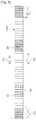
- FIG. 9illustrates the addressable RBGs in each cluster for the setup in FIG 5 , according to an embodiment of the present invention.
- a first cluster 910consists of the first 30 N RB PUSCH
- a second cluster 920consists of the last 30 N RB PUSCH
- the number of bits in the RA IE to address the RBGs in each clustermay not be sufficiently enough to capture each PRB of the N RB PUSCH
- PRB Set 1930 includes non-addressable PRBs, but this occurs only when the second cluster consists of only RBG 1.
- PRB Set 2940 consists of non-addressable PRBs, but this occurs only when the first cluster consists of only RBG 1.
- the RBG size of the first clustermay also be different than the RBG size of the second cluster.
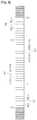
- PRBscan be respectively addressed in the first cluster and in the second cluster as shown according to an embodiment of the present invention in FIG. 10 .
- Both a first cluster 1010 and a second cluster 1020span all N RB PUSCH
- PRBsAnother aspect in FIG. 10 is the numbering of the RBGs for the second cluster, which, in general, can begin from the same BW side as the one for the first cluster.
- the full overlap of the first and second clusters in FIG. 10is only a coincidence of the assumed N RB HO value and full overlapping is not expected in general. This concept is illustrated according to an embodiment of the present invention in FIG. 11 , where the value of N RB HO may be interpreted as being equal to zero.
- PRBsmay be predetermined or informed to the UEs through 1 bit in a broadcast channel.
- the first cluster 1110 and the second cluster 1120span 40 PRBs and they partially overlap.
- the non-addressable PRBs, "PRB Set 1" 1130 and “PRB Set 2” 1140consist of only 2 PRBs and the probability of occurrence is negligible.
- PRB Set 1requires scheduling of the first cluster only in the first RBG, that the second RBG is not scheduled, and the second cluster needs to address the PRBs in "PRB Set 1".
- the overall UE procedure for processing a UL SAis described in FIG. 12 , according to an embodiment of the present invention.
- the UEfirst receives broadcast channels in step 1210, transmitted from the Node B, which inform the UE of the N RB UL value (UL operating bandwidth), and of the N RB HO value in step 1220.
- a broadcast channelmay also provide the RBG size G, or this size can be linked to the value of N RB UL
- PRBsis also linked to the value of N RB UL (or to the value of N RB DL corresponding to the DL operating BW which may be obtained from a broadcast channel prior to the UL operating BW).
- N RB UL25 50, or 100 PRBs
- the size of the RA IEis 9, 11, or 13 bits, respectively, in case of a single cluster.
- the RA sizemay be supplemented with the 1 bit from the FH IE.
- the size of the RA IEis 10, 12, or 14 bits, respectively, with half of these bits allocated to the first cluster and half allocated to the second cluster.
- a broadcast channelmay also inform the UE whether the PRB allocation in the RA IE of the UL SA is for PUSCH transmissions over N RB UL
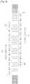
- the embodiments of the present inventionalso consider that the UL BW can be divided into a number of non-overlapping bands with each band constituting a separately addressable cluster.
- the UL BWmay consist of all N RB UL
- a few RBGssuch as for example RBG 7 1360 in the second cluster 1340, may contain fewer PRBs than the remaining RBGs if the total number of PRBs cannot be equally divided into an integer number of RBGs of equal size.
- PRBs12 bits are required for two clusters (six bits per cluster), with each cluster consisting of eight RBGs and one PRB for a total of nine addressable elements, and 13 bits are required for three clusters (four bits for the first and third clusters and five bits for the second cluster) as shown in FIG. 13 . Therefore, the RA IE requires 13 bits and for two clusters, one of these bits is set to a predetermined value such as 0.
- Both a first cluster 1410 and a second cluster 1420consist of 12 RBGs and one PRB 1430A, 1430B.
- the number of bits required for the allocation in each clusteris seven, resulting to a total of 14 RA bits for addressing both clusters.
- FIG. 15an alternative partitioning of the RBGs in the two clusters is illustrated in FIG. 15 , according to an embodiment of the present invention.
- This partitioningmaximizes the utilization of the number of bits in each of the two parts of the RA IE in order to address as many as possible elements in each part. Since a maximum of 10 contiguously allocated elements can be addressed with six bits and a maximum of 15 contiguously allocated elements can be addressed with seven bits, the partitioning in FIG. 15 considers that a first cluster 1510 consists of 10 RBGs and a second cluster 1520 consist of 15 RBGs.
Landscapes
- Engineering & Computer Science (AREA)
- Signal Processing (AREA)
- Computer Networks & Wireless Communication (AREA)
- Mobile Radio Communication Systems (AREA)
- Digital Transmission Methods That Use Modulated Carrier Waves (AREA)
Description
- The present invention relates generally to wireless communication systems and, more particularly, to a structure of scheduling assignments for the transmission of data signals.
- A communication system consists of a DownLink (DL), supporting the transmission of signals from a base station (Node B) to User Equipments (UEs), and an UpLink (UL), supporting the transmission of signals from UEs to the Node B. A UE, also commonly referred to as a terminal or a mobile station, may be fixed or mobile and may be a wireless device, a cellular phone, a personal computer device, etc. A Node B is generally a fixed station and may also be referred to as a Base Transceiver System (BTS), an access point, or some other terminology.
- DL signals consist of data signals, carrying information content, control signals, and Reference Signals (RS), which are also known as pilot signals. The Node B conveys DL data signals through a Physical Downlink Shared CHannel (PDSCH). The UEs convey UL data signals through a Physical Uplink Shared CHannel (PUSCH). The DL control signals may be of a broadcast or a UE-specific nature. Broadcast control signals convey system information to all UEs. UE-specific control signals can be used, among other purposes, to provide, to UEs, Scheduling Assignments (SAs) for PDSCH reception (DL SAs) or PUSCH transmission (UL SAs). SAs are transmitted through a Physical Downlink Control CHannel (PDCCH).
- The PDCCH is usually a major part of the total DL overhead and directly impacts the achievable DL system throughput. One method for reducing the PDCCH overhead is to scale the PDCCH size according to its required resources during each Transmission Time Interval (TTI). In 3GPP Long Term Evolution (LTE), where the Node B uses Orthogonal Frequency Division Multiple Access (OFDMA) as the DL transmission method, a Control Channel Format Indicator (CCFI) parameter transmitted through a Physical Control Format Indicator CHannel (PCFICH) indicates the number of Orthogonal Frequency Division Multiplexing (OFDM) symbols occupied by the PDCCH.
- A structure for the PDCCH and PDSCH transmission in the DL TTI is shown in
FIG. 1 . The DL TTI is assumed to consist of asingle sub-frame 110 having M OFDM symbols. APDCCH 120 occupies the first N OFDM symbols and aPDSCH 130 occupies the remaining M-N OFDM symbols. A PCFICH 140 is transmitted in some sub-carriers, also referred to as Resource Elements (REs), of the first OFDM symbol. Some OFDM symbols may contain RS REs, 150 and 160, for each of the Node B transmitter antennas. InFIG. 1 , it is assumed that there are two Node B transmitter antennas. Among the main purposes of the RS are to enable a UE to obtain an estimate for the DL channel medium it experiences and to perform other measurements and functions as they are known in the art. Additional control channels may be transmitted in the PDCCH region but, for brevity, they are not shown inFIG. 1 . For example, assuming the use of Hybrid Automatic Repeat reQuest (HARQ) for PUSCH transmissions, a Physical Hybrid-HARQ Indicator CHannel (PHICH) may be transmitted by the Node B to indicate to UEs whether their previous PUSCH transmissions were correctly or incorrectly received by the Node B. - The Node B separately encodes and transmits each of the UL SAs and DL SAs in the PDCCH. An SA encoding process is illustrated in
FIG. 2 . The DL SA or ULSA information bits 210, respectively conveying the information scheduling PDSCH reception or PUSCH transmission by a UE, are appended with Cyclic Redundancy Check (CRC) bits instep 220, and are subsequently encoded instep 230, for example using a convolutional code. The bits are rate matched to the assigned PDCCH resources instep 240, and transmitted instep 250. As a consequence, each UE may perform multiple decoding operations to determine whether it is assigned a DL SA or an UL SA in the corresponding sub-frame. Typically, the CRC of each SA is scrambled with an IDentity (ID) of the UE the SA is intended for. After descrambling using its ID, a UE can determine whether an SA is intended for the UE by performing a CRC check. - At the UE receiver, the inverse operations are performed to decode an SA as illustrated in
FIG. 3 . The received SA 310, is rate de-matched instep 320, decoded instep 330, and after the CRC is extracted instep 340, the SA information bits are obtained instep 350. As previously described, if the CRC check passes, the SA is considered to be intended for the UE. - A structure for the PUSCH transmission in the UL TTI, which is assumed to consist of one sub-frame, is shown in
FIG. 4 . Single-Carrier Frequency Division Multiple Access (SC-FDMA) is assumed to be the transmission method. Asub-frame 410 includes two slots. Eachslot 420 includes seven symbols used for the transmission of data or control signals. Eachsymbol 430 further includes a Cyclic Prefix (CP) to mitigate interference due to channel propagation effects. PUSCH transmission in one slot may be in the same or different part of the operating BandWidth (BW) than the PUSCH transmission in the other slot. PUSCH transmission in different BWs in each slot is referred to as Frequency Hopping (FH). Some symbols in each slot may be used forRS transmission 440 to provide channel estimation and to enable coherent demodulation of the received signal. The transmission BW is assumed to consist of frequency resource units, which are referred to as Physical Resource Blocks (PRBs). Each PRB is further assumed to consist of

consecutive PRBs 450 for its PUSCH transmission. - A conventional UL SA is described through an set of Information Elements (IEs) in Table 1. Additional IEs or a different number of bits for the indicative IEs in Table 1 may apply. The order of the IEs in a UL SA can be arbitrary. The length of the CRC (UE ID) is assumed to be 16 bits but other values, such as 20 bits or 24 bits, may be used instead.
[Table 1] IEs of an UL SA for PUSCH Transmission in Contiguous PRBs Information Element Number of Bits Comment Indication of UL SA 1 Indicates that the SA is for UL Transmission Resource Allocation (RA) 11 Assignment of Consecutive PRBs (total 50 PRBs) Modulation and Coding Scheme (MCS) 5 MCS Levels New Data Indicator (NDI) 1 New Data Indicator (synchronous HARQ) Transmission Power Control (TPC) 2 Power control commands Cyclic Shift Indicator (CSI) 3 SDMA (maximum of 8 UEs) Frequency Hopping (FH) 1 Frequency Hopping (Yes/No) Channel Quality Indicator (CQI) Request 1 Include CQI report (Yes/No) Unused Bit 1 To align the UL SA size with a DL SA size CRC (UE ID) 16 UE ID masked in the CRC TOTAL 42 - The first IE differentiates the UL SA from an SA used for a different purpose, such as, for example, for PDSCH scheduling (DL SA). The UL SA and the DL SA are desired to have the same size in order for both SAs to be examined with a single decoding operation at the UE.
- The second IE is a Resource Allocation (RA) IE, which specifies the assigned PRBs for PUSCH transmission. With SC-FDMA, the signal transmission BW is contiguous. For an operating BW of

- PRBs, the number of possible contiguous PRB allocations to a UE is


- PRBs assumed in Table 1, the number of required bits is 11. In general, regardless of the transmission method, the UL SA is assumed to contain an RA IE.
- The third IE indicates a Modulation and Coding Scheme (MCS) for the PUSCH transmission. With 5 bits, a total of 32 MCS values can be supported. For example, the modulation may be QPSK, QAM16, or QAM64, while the coding rate may take discrete values between, for example, 1/16 and 1. Some values of the MCS IE may be reserved to be used in support of HARQ. For example, the last 3 of the 32 MCS values may be used to indicate a Redundancy Version (RV) for a packet retransmission for the same Transport Block (TB). In that case, the MCS is determined from the MCS of the previous SA for the same TB, which is assumed to be specified with one of the first 29 MCS values.
- The fourth IE is a New Data Indicator (NDI). The NDI is set to 1 if a new TB should be transmitted, while it is set to 0 if the same TB, as in a previous transmission, should be transmitted by the UE (synchronous HARQ is assumed).
- The fifth IE provides a Transmission Power Control (TPC) command for power adjustments of the PUSCH transmission. For example, the 2 bits of the TPC IE in the UL SA, [00, 01, 10, 11], may respectively correspond to [-1, 0, 1, 3] deciBel (dB) adjustments of the PUSCH transmission power.
- The sixth IE is a Cyclic Shift (CS) Indicator (CSI) enabling the use of a different CS for a Constant Amplitude Zero Auto-Correlation (CAZAC) sequence assumed to be used for RS transmission in
FIG. 4 . The different CS of a CAZAC sequence, adequately separated in time, can result in orthogonal CAZAC sequences. This property can be used to orthogonally multiplex the RS transmission from different UEs in the same PRBs, in order to support Spatial Division Multiple Access (SDMA) for PUSCH transmissions. - The seventh IE indicates whether the UE should apply FH to its PUSCH transmission. For example, if the FH IE value is set to 1, the UE applies FH to its PUSCH transmission as previously explained and described in greater detail below.
- The eighth IE indicates whether the UE should include a Channel Quality Indicator (CQI) report in its PUSCH transmission. The CQI report provides the Node B with information about channel conditions the UE experiences in the DL. This information can enable the Node B to select parameters for PDSCH transmission to that UE, such as the MCS and PRBs, so that a performance metric, such as the system throughput or the UE throughput, is improved.
- The ninth IE is an unused bit, set to a predetermined value such as 0, which is assumed to be needed to pad the UL SA size in order to make it equal to the size of a DL SA.
- The transmission mode for the UL SA described in Table 1 corresponds to PUSCH transmission from a single UE antenna or to antenna transmission diversity. A different UL SA can be defined for a transmission mode corresponding to PUSCH transmission from a UE using a Multiple Input Multiple Output (MIMO) transmission principle.
- In an FH operation, a total number of PUSCH PRBs is defined as


FIG. 5 where
PRBs 510,
PRBs 520, which are equally divided on each side of the BW, and
PRBs 530. A total of 5PRBs 540 are allocated to the PUSCH transmission by a UE starting from PRB 11 550 in the first slot and PRB number 31 560 in the second slot. Several other realizations of the FH operation are also possible.- In addition to SC-FDMA, where the signal transmission is over a contiguous BW (single cluster of consecutive PRBs with RA IE as described in Table 1), the same transmitter and receiver structure can be used for signal transmission over multiple clusters (non-contiguous sets of PRBs). Because a Discrete Fourier Transform (DFT) is applied to the signal transmission, this method is known as DFT-Spread-OFDM (DFT-S-OFDM). For a single cluster, DFT-S-OFDM is identical to SC-FDMA. For a number of clusters equal to the number of REs in the operating BW, DFT-S-OFDM becomes identical to conventional OFDM.
- A block diagram of the transmitter functions for clustered OFDM signaling is illustrated in
FIG. 6 . Encodeddata bits 610 are applied to aDFT 620, RE mapping 630 for the assigned transmission BW are selected through control of localized Frequency Division Multiple Access (FDMA) 640 (zeros are mapped to non-selected REs). Inverse Fast Fourier Transform (IFFT) 650 and CP insertion is performed,time windowing filtering 670 is applied and thesignal 680 is transmitted. Additional transmitter circuitry such as a digital-to-analog converter, analog filters, and transmitter antennas are not shown. Also, the encoding and modulation process for the data bits is omitted. The selected REs after the DFT may be in a single cluster ofcontiguous REs 690 or they may be in multiple clusters ofcontiguous REs 695. - At the receiver, the reverse (complementary) transmitter operations are performed as illustrated in
FIG. 7 . After an antenna receives a Radio-Frequency (RF) analog signal and after further processing units (such as filters, amplifiers, frequency down-converters, and analog-to-digital converters) which are not shown,digital signal 710 is filtered attime windowing 720 and continues throughCP removal 730. Subsequently, the receiver unit applies anFFT 740, demaps theREs 760 used by the transmitter through control of the reception bandwidth 750 (zeros are appended for the remaining REs), applies an Inverse DFT (IDFT) 770 and obtains receivedcoded data bits 780. Well known receiver functionalities such as channel estimation, demodulation, and decoding are not shown. - There are several issues associated with the design of the control signaling required for supporting contiguous PRB allocations in conjunction with the control signaling required for supporting non-contiguous PRB allocations for a given transmission mode.
- A first issue is to avoid introducing different UL SA sizes depending on the number of clusters specified by the RA IE in the UL SA. Assuming that the remaining IEs, as described in Table 1, remain unchanged, different RA IE sizes for addressing a different number of PRB clusters will lead to different UL SA sizes. Since a UE cannot know in advance the number of its allocated PRB clusters, it will have to decode each UL SA corresponding to each possible RA size. This will lead to an increase in the number of decoding operations the UE needs to perform and a respective increase in the PDCCH decoding complexity. For example, if allocations of one cluster of PRBs and allocations of two clusters of PRBs are supported, with each requiring a different UL SA size, the number of decoding operations for the UL SAs is doubled relative to their respective number when only allocation of one cluster of PRBs is supported.
- A second issue is that by allowing a large number for clusters of PRBs to be allocated, the respective size of the RA IE in the UL SA may substantially increase, thereby leading to an increase in the total UL SA size and an increase in the associated PDCCH overhead.
- Prior art documentR1-084077 from 3GPP TSG-RAN Meeting #54bis; Pub. October 2008, is a 3GPP change request document which discloses a downlink resource allocation type where a one bit flag indicates whether localized virtual resource blocks or distributed virtual resource blocks are assigned.
- Therefore, there is a need to support control signaling for scheduling PUSCH transmissions over non-contiguous PRB allocations by limiting the number of PRB clusters addressable in the RA IE of the respective UL SA.
- There is another need to avoid increasing the number of decoding operations associated with UL SAs supporting PUSCH transmissions over non-contiguous PRB allocations.
- Finally, there is another need to maintain a small UL SA size for supporting PUSCH transmissions over non-contiguous PRB allocations to avoid increasing the PDCCH overhead.
- The present invention has been made to address at least the above problems and/or disadvantages and to provide at least the advantages described below. Accordingly, an aspect of the present invention provides methods and apparatus for the transmission of a data signal with a certain transmission mode by a UE over a contiguous bandwidth or over multiple non-contiguous clusters with each cluster having a contiguous bandwidth.
- According to one aspect of the present invention, a method is provided for transmitting a data signal from a User Equipment (UE) to a Node B in a communication system using a transmission mode. The data signal is transmitted over a single contiguous bandwidth in response to a first scheduling assignment received at the UE from the Node B. The data signal is transmitted over multiple non-contiguous clusters in response to a second scheduling assignment received at the UE from the Node B. Each non-contiguous cluster has a contiguous bandwidth. A size of the first scheduling assignment is substantially equal to the size of the second scheduling assignment.
- According to another aspect of the present invention, a method is provided for transmitting a data signal from a User Equipment (UE) to a Node B in a communication system using a transmission mode. The data signal is transmitted over a single contiguous bandwidth in response to a scheduling assignment having a plurality of information elements received at the UE from the Node B, when one of the plurality of information elements has a first value. The plurality of information elements include binary elements. The data signal is transmitted over multiple non-contiguous clusters with each cluster having a contiguous bandwidth in response to the scheduling assignment, when the one of the plurality of information elements has a second value.
- According to an additional aspect of the present invention, a User Equipment (UE) apparatus is provided for transmitting data signals to a Node B using a transmission mode. The UE apparatus includes a transmitter operating in a first mode for transmitting a data signal over a single contiguous bandwidth in response to a first scheduling assignment received at the UE from the Node B. The UE apparatus also includes a transmitter operating in a second mode for transmitting a data signal over multiple non-contiguous clusters in response to a second scheduling assignment received at the UE from the Node B. Each non-contiguous cluster has a contiguous bandwidth. A size of the first scheduling assignment is substantially equal to a size of the second scheduling assignment.
- According to a further aspect of the present invention a User Equipment (UE) apparatus is provided for transmitting a data signal to a Node B using a transmission mode. The UE apparatus includes a transmitter operating in a first mode for transmitting the data signal over a single contiguous bandwidth in response to a scheduling assignment having a plurality of information elements received at the UE from the Node B, when one of the plurality of information elements has a first value, wherein the plurality of information elements include binary elements. The UE apparatus also includes a transmitter operating in a second mode for transmitting the data signal over multiple non-contiguous clusters with each cluster having a contiguous bandwidth, in response to the scheduling assignment, when the one of the plurality of information elements has a second value.
- The present invention can provide methods and apparatus for the transmission of a data signal with a certain transmission mode by a UE over a contiguous bandwidth or over multiple non-contiguous clusters with each cluster having a contiguous bandwidth.
- The above and other aspects, features, and advantages of the present invention will be more apparent from the following detailed description when taken in conjunction with the accompanying drawings, in which:
FIG. 1 is a diagram illustrating a DL sub-frame structure for PDCCH and PDSCH transmissions in the DL of the communication system;FIG. 2 is a block diagram illustrating an encoding process for a scheduling assignment;FIG. 3 is a block diagram illustrating a decoding process for a scheduling assignment;FIG. 4 is a diagram illustrating a UL sub-frame structure;FIG. 5 is a diagram illustrating the application of the frequency hopping operation for data signal transmission in the UL of the communication system;FIG. 6 is a block diagram illustrating a DFT-S-FDMA transmitter;FIG. 7 is a block diagram illustrating a DFT-S-FDMA receiver;FIG. 8 is a diagram illustrating a resource allocation mapping for DFT-S-FDMA signal transmission in two non-contiguous clusters of contiguous bandwidth, according to an embodiment of the present invention;FIG. 9 is a diagram illustrating a first addressing method of resource block groups for the resource allocation mapping for DFT-S-FDMA signal transmission in two non-contiguous clusters of contiguous bandwidth, according to an embodiment of the present invention;FIG. 10 is a diagram illustrating a second method for addressing resource block groups over the PUSCH hopping bandwidth for the resource allocation mapping for DFT-S-FDMA signal transmission in two non-contiguous clusters of contiguous bandwidth, according to an embodiment of the present invention;FIG. 11 is a diagram illustrating the second method for addressing resource block groups over the operating bandwidth for the resource allocation mapping for DFT-S-FDMA signal transmission in two non-contiguous clusters of contiguous bandwidth, according to an embodiment of the present invention;FIG. 12 is a block diagram illustrating the overall UE procedure for processing an UL scheduling assignment, according to an embodiment of the present invention;FIG. 13 is a diagram illustrating the division of the UL bandwidth into a number of non-overlapping frequency bands with each band constituting a separately addressable cluster, according to an embodiment of the present invention;FIG. 14 is a diagram illustrating the adaptation of the resource block group size used as the bandwidth unit for data signal transmission on the number of assigned clusters, according to an embodiment of the present invention; andFIG. 15 is a diagram illustrating a partitioning of the resource block groups in order to obtain the same number of bits for specifying the resource allocation when the partitioning of the scheduling bandwidth is over two or three clusters, according to an embodiment of the present invention.- The invention made is disclosed in the attached set of independent claims. Further embodiments are disclosed in the attached set of dependent claims.
- Embodiments of the present invention are described in detail with reference to the accompanying drawings. The same or similar components may be designated by the same or similar reference numerals although they are illustrated indifferent drawings. Detailed descriptions of constructions or processes known in the art may be omitted to avoid obscuring the subject matter of the present invention.
- Additionally, although the present invention is described in relation to an OFDMA communication system, it also applies to all Frequency Division Multiplexing (FDM) systems in general and to SC-FDMA, OFDM, Frequency Division Multiple Access (FDMA), DFT-S-OFDM, DFT-Spread OFDMA, SC?OFDMA, and SC-OFDM in particular.
- The invention considers that the same UL SA is used for contiguous PRB allocations and for non-contiguous PRB allocations. In an embodiment of the present invention, the number of PRB clusters addressable by the UL SA is limited to one (contiguous PRB allocations) and two (non-contiguous PRB allocations).
- The UE can be semi-statically or dynamically informed as to whether the PUSCH transmission is in contiguous PRBs or in non-contiguous PRBs by the Node B. Semi-static configuration of the PUSCH transmission structure can be through higher layer signaling, such as Radio Resource Control (RRC) signaling. Dynamic configuration can be through the UL SA.
- An embodiment of the present invention considers that enabling the use of the same UL SA for addressing contiguous and non-contiguous PRB allocations is based on the following principles:
- a) The unused bit in the UL SA described in Table 1 is utilized to indicate whether the RA is for contiguous PRB allocations (for example, a value of 0) or for non-contiguous PRB allocations (for example, a value of 1). In the following description, this bit is assumed to correspond to a "RA indication" IE. This is applicable for dynamic configuration of the PUSCH transmission structure. Otherwise, for RRC configuration, the unused bit in the UL SA described in Table 1 may remain unutilized.
- b) FH may not be applicable for non-contiguous PRB allocations. Then, the corresponding 1 bit in the FH IE may be utilized to supplement the existing RA IE in the UL SA or it may be utilized for other purposes.
- c) When the "RA Indication" IE is for non-contiguous PRB allocations:
- a. The RA IE also includes the 1 bit from the FH IE.
- b. The addressable PRBs may include only the


- c. The addressable PRBs may be grouped in RB Groups (RBGs) of G > 1 PRBs.
- d. Half of the bits of the RA IE may be used to address the first PRB cluster and the remaining half may be used to address the second PRB cluster. If the number of bits R in the RA IE is not even, then


- e. The PRBs of the first cluster start from the lowest frequency (lowest numbered PRB) and are indexed in an ascending order while the PRBs of the second cluster start from the highest frequency (highest numbered PRB) and are indexed in a descending order.
- FH for non-contiguous PRB allocations is not supported because the additional diversity gain is negligible compared to that achieved with FH for contiguous PRB allocations together with multiple transmission or reception antennas.
- The interpretation of the UL SA IEs described in Table 1 with non-contiguous PRB allocations is described in Table 2. In this embodiment of the present invention, the FH bit is included to supplement the RA IE, as FH is not supported, and a value of 1 for the unused bit, which is now the "RA Indication" IE (in case of dynamic configuration), is considered as valid.
[Table 2] IEs of an UL SA for PUSCH Transmission in 2 PRBs Clusters Information IE Number of Bits Comment Indication of UL SA 1 May indicate that the SA is for UL Transmission Resource Allocation (RA) 11+1=12 Assignment of Consecutive PRBs (total 50 PRBs) Modulation and Coding Scheme (MCS) 5 MCS Levels New Data Indicator (NDI) 1 New Data Indicator (synchronous HARQ) Transmission Power Control (TPC) 2 Power control commands Cyclic Shift Indicator (CSI) 3 SDMA (maximum of S UEs) Frequency Hopping (FH) N/A Frequency Hopping (Yes/No) Channel Quality Indicator (CQI) Request 1 Include CQI report (Yes/No) RA Indication Bit 1 Value of 1 indicates 2 PRB Clusters CRC (UE ID) 16 UE ID masked in the CRC TOTAL 4 2 - As previously described for dynamic configuration, when the RA indication bit is 1, half of the bits of the RA IE are interpreted as indicating the contiguous PRBs for the first cluster and the remaining half are interpreted as indicating the contiguous PRBs for the second cluster. Moreover, the PRBs are allocated in groups of G PRBs. Using the setup of
FIG. 5 as reference, the RA principle of this embodiment of the present invention for 2 clusters is illustrated inFIG. 8 . A first cluster 810 begins from the lowest
- PRBs, which are grouped into
RBG 1,RBG 2, etc. 820, with each RBG having
- PRBs. A
second cluster 830 begins from the highest
- PRBs, which are also grouped into the
respective RBG 1,RBG 2, etc. 840, with each RBG again having
- The interpretation of the RA IE for non-contiguous PRB allocations over two clusters is subsequently described for an embodiment of the present invention considering the RA IE size of 12 bits in Table 2. The first 6 bits are used to address RBGs in the first cluster and the second 6 bits are used to address RBGs in the second cluster. With 6 bits, the total number of contiguous RBGs that can be addressed is 10. Therefore, for

- PRBs per RBG, the first 30 and the last 30 of the

- PRBs can be respectively addressed in the first cluster and in the second cluster.
FIG. 9 illustrates the addressable RBGs in each cluster for the setup inFIG 5 , according to an embodiment of the present invention. Afirst cluster 910 consists of the first 30
- PRBs, starting from the lowest one, resulting in 10 RBGs. A
second cluster 920 consists of the last 30
- PRBs, again resulting in 10 RBGs. The number of bits in the RA IE to address the RBGs in each cluster may not be sufficiently enough to capture each PRB of the

- PRBs. However, the occurrence of scheduling decisions that cannot be achieved due to non-addressable PRBs is rare. For the setup in
FIG. 9 , "PRB Set 1" 930 includes non-addressable PRBs, but this occurs only when the second cluster consists ofonly RBG 1. Similarly, "PRB Set 2" 940 consists of non-addressable PRBs, but this occurs only when the first cluster consists ofonly RBG 1. These occurrences are highly non-typical and have a negligible impact on the average user throughput and on the average cell throughput of the communication system. - The RBG size of the first cluster may also be different than the RBG size of the second cluster. For example, the first cluster may use

- PRBs per RBG while the second cluster may use

- PRBs per RBG. The tradeoff from having a smaller RBG size for the second cluster is the increased RA granularity at the expense of a reduced range of captured PRBs by the RA IE. However, this reduced range is not important given that the cluster with the larger RBG size can practically address the entire BW.
- To avoid having non-addressable PRBs, such as "
PRB Set 1" inFIG. 9 , the RBG size may be increased. For example, for the setup inFIG. 9 , by increasing the RBG size to
- PRBs per RBG, the first 40 and the last 40 of the

- PRBs can be respectively addressed in the first cluster and in the second cluster as shown according to an embodiment of the present invention in
FIG. 10 . Both afirst cluster 1010 and asecond cluster 1020 span all
- PRBs. Another aspect in
FIG. 10 is the numbering of the RBGs for the second cluster, which, in general, can begin from the same BW side as the one for the first cluster. The full overlap of the first and second clusters inFIG. 10 is only a coincidence of the assumed
FIG. 11 , where the value of
- In order to provide scheduling capability over the entire operating BW of

- PRBs, which also corresponds to the case of

first cluster 1110 may start from the leftmost (bottom) side of the operating BW and asecond cluster 1120 may start from the rightmost (top) side of the operating BW, as shown inFIG. 11 , where it is again assumed that the RBG size is
- PRBs. Whether the RA IE addresses PRBs over the entire operating BW of

- PRBs or over only the

- PRBs may be predetermined or informed to the UEs through 1 bit in a broadcast channel. The
first cluster 1110 and thesecond cluster 1120 span 40 PRBs and they partially overlap. The non-addressable PRBs, "PRB Set 1" 1130 and "PRB Set 2" 1140 consist of only 2 PRBs and the probability of occurrence is negligible. For example, "PRB Set 1" requires scheduling of the first cluster only in the first RBG, that the second RBG is not scheduled, and the second cluster needs to address the PRBs in "PRB Set 1". - The overall UE procedure for processing a UL SA is described in
FIG. 12 , according to an embodiment of the present invention. The UE first receives broadcast channels instep 1210, transmitted from the Node B, which inform the UE of the

step 1220. The UE can then compute the


- . For example, for


- PRBs, is also linked to the value of


- PRBs (the entire UL operating BW) or over only

- PRBs; otherwise, the selected option can be included in the specifications for the system operation.
- The embodiments of the present invention also consider that the UL BW can be divided into a number of non-overlapping bands with each band constituting a separately addressable cluster. The UL BW may consist of all

- PRBs or it may consist of only the

- PRBs.
FIG. 13 illustrates this principle, according to an embodiment of the present invention, where all
- PRBs are considered and are divided into


example RBG 7 1360 in thesecond cluster 1340, may contain fewer PRBs than the remaining RBGs if the total number of PRBs cannot be equally divided into an integer number of RBGs of equal size. - The interpretation of the UL SA IEs described in Table 1 in case of non-contiguous PRB allocations is described in Table 3. As this UL SA assigns only non-contiguous PRB allocations and has a different size than the UL SA for contiguous only PRB allocations, there is no need to have an IE to discriminate between the two UL SAs, even in the case of dynamic configuration for each of the two PUSCH transmission structures.
[Table 3] IEs of an UL SA for PUSCH Transmission in two or three PRBs Clusters. Information IE Number of Bits Comment Cluster Number Indicator (CNI) 1 Indicates number of PUSCH Clusters (2 or 3) Resource Allocation (RA) 13 Assignment of Consecutive PRBs (total 50 PRBs) Modulation and Coding Scheme (MCS) 5 MCS Levels New Data Indicator (NDI) 1 New Data Indicator (synchronous HARQ) Transmission Power Control (TPC) 2 Power control commands Cyclic Shift Indicator (CSI) 3 SDMA (maximum of 8 UEs) Frequency Hopping (FH) 1 Frequency Hopping (Yes/No) Channel Quality Indicator (CQI) Request 1 Include CQI report (Yes/No) CRC (UE ID) 16 UE ID masked in the CRC TOTAL 43 - The difference of the UL SA in Table 3 relative to the UL SA in Table 1 is in the following IEs:
- a) Cluster Number Indicator (CNI): This IE is unique to the UL SA in Table 3 and indicates the number of clusters for the scheduled PUSCH transmission and its value determined the interpretation of the RA IE.
- b) RA: Depending on the CNI value, the RA IE addresses two or three clusters. If the CNI indicates two clusters, the number of RA bits is divided into two parts with an equal number of bits if the RA size is an even number. Otherwise, the first part has one more bit than the second part. If the CNI indicates three clusters, the number of RA bits is divided into three parts with an equal number of bits if the RA size is a multiple of three. Otherwise, the middle part has one more (or one less) bit than the first and third parts.
- For example, for

- PRBs and an RBG size of

- PRBs, 12 bits are required for two clusters (six bits per cluster), with each cluster consisting of eight RBGs and one PRB for a total of nine addressable elements, and 13 bits are required for three clusters (four bits for the first and third clusters and five bits for the second cluster) as shown in
FIG. 13 . Therefore, the RA IE requires 13 bits and for two clusters, one of these bits is set to a predetermined value such as 0. - An alternative embodiment of the present invention considers that the RBG size depends on the number of assigned clusters. For example, a smaller RBG size can be assigned to a smaller number of clusters. This is illustrated in
FIG. 14 , according to an embodiment of the present invention, where for two clusters the RBG size is
- . For three clusters, the RBG size is

- . Both a
first cluster 1410 and asecond cluster 1420 consist of 12 RBGs and onePRB - In order to obtain the same number of bits for the RA IE when the partitioning of the scheduling BW is over two and three clusters, an alternative partitioning of the RBGs in the two clusters is illustrated in
FIG. 15 , according to an embodiment of the present invention. This partitioning maximizes the utilization of the number of bits in each of the two parts of the RA IE in order to address as many as possible elements in each part. Since a maximum of 10 contiguously allocated elements can be addressed with six bits and a maximum of 15 contiguously allocated elements can be addressed with seven bits, the partitioning inFIG. 15 considers that afirst cluster 1510 consists of 10 RBGs and asecond cluster 1520 consist of 15 RBGs. The total number of RA bits is 13, which is the same as the one for three clusters and RBG size of
FIG. 13 .


Claims (11)
- A communication method between a user equipment, UE, and a node B in a communication system, the communication method comprising:receiving (1210) a scheduling assignment including a resource allocation indication, a resource allocation, a modulation and coding scheme, MCS, and a frequency hopping information element, from the node B; andtransmitting data on resource blocks indicated by the scheduling assignment to the node B,wherein the resource allocation indication indicates whether the resource allocation is for a cluster of at least one contiguous resource block or two clusters of resource blocks, wherein each of the two clusters of resource blocks comprises one or more consecutive resource block groups,wherein the frequency hopping information element is used as part of the resource allocation to specify the assigned resource blocks if the resource allocation is for the two clusters (1310, 1320) of resource blocks.
- The method of claim 1, wherein the one frequency hopping information element is used for indicating on/off of frequency hopping if the resource allocation is for the set of at least one contiguous resource block.
- The method of claim 1, wherein if the resource allocation is for the two clusters of resource blocks, a half of bits of the resource allocation is for a former half of bits of the two clusters and the other half of bits of the resource allocation is for a latter half of bits of the two clusters.
- The method of claim 1, wherein a size of the resource block groups depends on a system bandwidth.
- A communication method between a user equipment, UE, and a node B in a communication system, the communication method comprising:transmitting a scheduling assignment including a resource allocation indication, a resource allocation, a modulation and coding scheme, MCS, and a frequency hopping information element, to the UE; andreceiving data on resource blocks indicated by the scheduling assignment from the UE,wherein the resource allocation indication indicates whether the resource allocation is for a cluster of at least one contiguous resource block or two clusters of resource blocks, wherein each of the two clusters comprises one or more consecutive resource block groups,wherein the frequency hopping information element is used as part of the resource allocation to specify the assigned resource blocks if the resource allocation is for the two clusters of resource blocks.
- The method of claim 5, wherein the frequency hopping information element is used for indicating on/off of frequency hopping if the resource allocation is for the cluster of at least one contiguous resource block.
- The method of claim 5, wherein if the resource allocation is for the two clusters of resource blocks, a half of bits of the resource allocation is for a former half of bits of the two clusters and the other half of bits of the resource allocation is for a latter half of bits of the two clusters.
- The method of claim 5, wherein a size of the resource block groups depends on a system bandwidth.
- An apparatus of a user equipment, UE, for transmitting data to a node B in a communication system, the apparatus comprising:a receiver configured to receive a scheduling assignment including a resource allocation indication, a resource allocation, a modulation and coding scheme, MCS, and a frequency hopping information element, from the node B; anda transmitter configured to transmit data on resource blocks indicated by the scheduling assignment to the node B,wherein the resource allocation indication indicates whether the resource allocation is for a cluster of at least one contiguous resource block or two clusters of resource blocks, wherein each of the two clusters comprises one or more consecutive resource block groups,wherein the frequency hopping information element is used as part of the resource allocation to specify the assigned resource blocks if the resource allocation is for the two clusters of resource blocks.
- An apparatus of a Node B for receiving data from a user equipment, UE, in a communication system, the apparatus comprising:a transmitter configured to transmit a scheduling assignment including a resource allocation indication, a resource allocation, a modulation and coding scheme, MCS, and a frequency hopping information element, to the UE; anda receiver configured to receive data on resource blocks indicated by the scheduling assignment from the UE,wherein the resource allocation indication indicates whether the resource allocation is for a cluster of at least one contiguous resource block or two clusters of resource blocks, wherein each of the two clusters comprises one or more consecutive resource block groups,wherein the frequency hopping information element is used as part of the resource allocation to specify the assigned resource blocks if the resource allocation is for the two sets of resource blocks.
- The apparatus of claim 9 or 10, adapted to perform the method of one of claims 2 to 4 and 6 to 8.
Applications Claiming Priority (3)
| Application Number | Priority Date | Filing Date | Title |
|---|---|---|---|
| US14868209P | 2009-01-30 | 2009-01-30 | |
| EP10736034.9AEP2384599B1 (en) | 2009-01-30 | 2010-01-29 | Control signaling for transmissions over contiguous and non-contiguous frequency bands |
| PCT/KR2010/000547WO2010087643A2 (en) | 2009-01-30 | 2010-01-29 | Control signaling for transmissions over contiguous and non-contiguous frequency bands |
Related Parent Applications (1)
| Application Number | Title | Priority Date | Filing Date |
|---|---|---|---|
| EP10736034.9ADivisionEP2384599B1 (en) | 2009-01-30 | 2010-01-29 | Control signaling for transmissions over contiguous and non-contiguous frequency bands |
Publications (2)
| Publication Number | Publication Date |
|---|---|
| EP3131358A1 EP3131358A1 (en) | 2017-02-15 |
| EP3131358B1true EP3131358B1 (en) | 2020-09-23 |
Family
ID=42396200
Family Applications (2)
| Application Number | Title | Priority Date | Filing Date |
|---|---|---|---|
| EP10736034.9AActiveEP2384599B1 (en) | 2009-01-30 | 2010-01-29 | Control signaling for transmissions over contiguous and non-contiguous frequency bands |
| EP16190949.4AActiveEP3131358B1 (en) | 2009-01-30 | 2010-01-29 | Control signaling for transmissions over contiguous and non-contiguous frequency bands |
Family Applications Before (1)
| Application Number | Title | Priority Date | Filing Date |
|---|---|---|---|
| EP10736034.9AActiveEP2384599B1 (en) | 2009-01-30 | 2010-01-29 | Control signaling for transmissions over contiguous and non-contiguous frequency bands |
Country Status (9)
| Country | Link |
|---|---|
| US (3) | US8160016B2 (en) |
| EP (2) | EP2384599B1 (en) |
| JP (4) | JP5194177B2 (en) |
| KR (1) | KR101640624B1 (en) |
| CN (2) | CN103648171B (en) |
| AU (1) | AU2010208778B2 (en) |
| CA (1) | CA2750580C (en) |
| ES (1) | ES2608810T3 (en) |
| WO (1) | WO2010087643A2 (en) |
Families Citing this family (40)
| Publication number | Priority date | Publication date | Assignee | Title |
|---|---|---|---|---|
| JP2596544Y2 (en) | 1993-12-24 | 1999-06-14 | 積水化成品工業株式会社 | Resin lightweight laminate |
| US8730933B2 (en)* | 2008-09-18 | 2014-05-20 | Qualcomm Incorporated | Method and apparatus for multiplexing data and reference signal in a wireless communication system |
| US8687575B2 (en) | 2008-11-14 | 2014-04-01 | Panasonic Corporation | Wireless communication terminal apparatus, wireless communication base station apparatus, and cluster constellation setting method |
| US8379581B2 (en)* | 2008-12-08 | 2013-02-19 | Sharp Kabushiki Kaisha | Systems and methods for uplink power control |
| SMT201800526T1 (en) | 2009-02-18 | 2018-11-09 | Sun Patent Trust | Scheduling apparatus and scheduling method |
| US20120002633A1 (en)* | 2009-03-17 | 2012-01-05 | Mitsubishi Electric Corporation | Communication system, communication apparatus, and frequency allocation method |
| WO2010140826A2 (en)* | 2009-06-03 | 2010-12-09 | Samsung Electronics Co., Ltd. | Selective application of frequency hopping for transmission of control signals |
| US9288026B2 (en)* | 2009-06-22 | 2016-03-15 | Qualcomm Incorporated | Transmission of reference signal on non-contiguous clusters of resources |
| WO2011016252A1 (en)* | 2009-08-07 | 2011-02-10 | パナソニック株式会社 | Radio base station and radio communication method |
| US9055576B2 (en)* | 2009-10-08 | 2015-06-09 | Qualcomm Incorporated | Uplink resource allocation for LTE advanced |
| JP5528123B2 (en)* | 2010-01-05 | 2014-06-25 | シャープ株式会社 | COMMUNICATION DEVICE, COMMUNICATION DEVICE CONTROL PROGRAM, AND INTEGRATED CIRCUIT |
| JP4912478B2 (en)* | 2010-02-09 | 2012-04-11 | シャープ株式会社 | Mobile station apparatus, radio communication method and circuit apparatus |
| US9407409B2 (en)* | 2010-02-23 | 2016-08-02 | Qualcomm Incorporated | Channel state information reference signals |
| JP5455228B2 (en)* | 2010-04-05 | 2014-03-26 | 株式会社Nttドコモ | Base station apparatus and user terminal |
| US8886250B2 (en) | 2010-06-18 | 2014-11-11 | Qualcomm Incorporated | Channel quality reporting for different types of subframes |
| US9515773B2 (en)* | 2010-04-13 | 2016-12-06 | Qualcomm Incorporated | Channel state information reporting in a wireless communication network |
| US20110250919A1 (en) | 2010-04-13 | 2011-10-13 | Qualcomm Incorporated | Cqi estimation in a wireless communication network |
| US9307431B2 (en) | 2010-04-13 | 2016-04-05 | Qualcomm Incorporated | Reporting of channel properties in heterogeneous networks |
| US9350475B2 (en) | 2010-07-26 | 2016-05-24 | Qualcomm Incorporated | Physical layer signaling to user equipment in a wireless communication system |
| US9485069B2 (en)* | 2010-04-15 | 2016-11-01 | Qualcomm Incorporated | Transmission and reception of proximity detection signal for peer discovery |
| US9510335B2 (en)* | 2010-05-26 | 2016-11-29 | Lg Electronics Inc. | Method and apparatus for transceiving control information for uplink multi-antenna transmission |
| US20130121278A1 (en)* | 2010-06-01 | 2013-05-16 | Lg Electronics Inc. | Method and apparatus for allocating resources in a wireless communication system |
| MY156711A (en)* | 2010-06-21 | 2016-03-15 | Panasonic Ip Corp America | Wireless Communication Apparatus, Allocated Resource Notifying Method and Data Allocating Method |
| US9148204B2 (en)* | 2010-06-21 | 2015-09-29 | Qualcomm Incorporated | Physical resource block (PRB) bundling for open loop beamforming |
| US9136953B2 (en) | 2010-08-03 | 2015-09-15 | Qualcomm Incorporated | Interference estimation for wireless communication |
| WO2012064248A1 (en)* | 2010-11-12 | 2012-05-18 | Telefonaktiebolaget L M Ericsson (Publ) | Multi-standard radio network node configuration data handling for network operation |
| US8855000B2 (en) | 2011-04-28 | 2014-10-07 | Qualcomm Incorporated | Interference estimation using data traffic power and reference signal power |
| JP5432210B2 (en)* | 2011-05-02 | 2014-03-05 | 株式会社Nttドコモ | User terminal, radio base station, downlink control channel receiving method, and mobile communication system |
| JP5832913B2 (en)* | 2012-01-27 | 2015-12-16 | シャープ株式会社 | COMMUNICATION SYSTEM, MOBILE STATION DEVICE, BASE STATION DEVICE, COMMUNICATION METHOD, AND INTEGRATED CIRCUIT |
| WO2013182507A2 (en)* | 2012-06-05 | 2013-12-12 | Telefonica, S.A. | A method for radio resources usage reporting in a lte network and uses thereof for interference reduction and for energy optimization |
| EP2962485B1 (en) | 2013-03-01 | 2019-08-21 | Intel IP Corporation | Wireless local area network (wlan) traffic offloading |
| US11240842B2 (en)* | 2016-01-08 | 2022-02-01 | Acer Incorporated | Device and method of handling transmission/reception for serving cell |
| WO2017126579A1 (en)* | 2016-01-20 | 2017-07-27 | 株式会社Nttドコモ | User terminal, wireless base station, and wireless communication method |
| WO2017222137A2 (en)* | 2016-06-22 | 2017-12-28 | Lg Electronics Inc. | Method and apparatus for allocating resources to fdr-mode ue in a wireless communication system |
| EP3480967B1 (en)* | 2016-06-30 | 2021-05-19 | Panasonic Intellectual Property Corporation of America | Transmitting device and transmitting method |
| GB2555612B (en)* | 2016-11-04 | 2021-06-16 | Tcl Communication Ltd | Systems and methods for allocation of wireless resources |
| CN110612762B (en) | 2017-06-08 | 2024-05-17 | Oppo广东移动通信有限公司 | Data transmission method, terminal device and network device |
| SG11202001883VA (en)* | 2017-09-08 | 2020-04-29 | Guangdong Oppo Mobile Telecommunications Corp Ltd | Method and apparatus for determining frequency hopping of channel, and computer storage medium |
| KR102542403B1 (en) | 2017-09-29 | 2023-06-12 | 삼성전자 주식회사 | Resource configuraiton and data transmission and reception method and apparatus in wirelss cellular communication system |
| WO2019095232A1 (en)* | 2017-11-16 | 2019-05-23 | 富士通株式会社 | Resource indication method, device and communication system |
Family Cites Families (43)
| Publication number | Priority date | Publication date | Assignee | Title |
|---|---|---|---|---|
| US6018528A (en)* | 1994-04-28 | 2000-01-25 | At&T Corp | System and method for optimizing spectral efficiency using time-frequency-code slicing |
| US6307868B1 (en)* | 1995-08-25 | 2001-10-23 | Terayon Communication Systems, Inc. | Apparatus and method for SCDMA digital data transmission using orthogonal codes and a head end modem with no tracking loops |
| GB9901356D0 (en)* | 1999-01-22 | 1999-03-10 | Central Research Lab Ltd | Method of and apparatus for the transmission of a plurality of signals |
| US7227884B2 (en)* | 2000-02-28 | 2007-06-05 | Aeroastro, Inc. | Spread-spectrum receiver with progressive fourier transform |
| KR100659198B1 (en)* | 2000-05-17 | 2006-12-21 | 유티스타콤코리아 유한회사 | Base station system of mobile communication system |
| JP2002112326A (en) | 2000-10-02 | 2002-04-12 | Ntt Docomo Inc | Radio resource allocation method and base station apparatus |
| US7577118B2 (en)* | 2001-07-24 | 2009-08-18 | Intel Corporation | System and method of classifying remote users according to link quality, and scheduling wireless transmission of information to the to the users based upon the classifications |
| US8134994B2 (en)* | 2003-02-14 | 2012-03-13 | Alcatel Lucent | Method of scheduling on downlink and transmitting on uplink dedicated channels |
| US20070183515A1 (en)* | 2004-02-27 | 2007-08-09 | Matsushita Electric Industrial Co., Ltd. | Method and apparataus for transmitting data in a multi-antenna wireless system |
| KR20060006725A (en)* | 2004-07-16 | 2006-01-19 | 삼성전자주식회사 | Method and apparatus for parameter determination for autonomous transmission in mobile communication system supporting enhanced uplink dedicated channel |
| US7961609B2 (en)* | 2004-07-20 | 2011-06-14 | Qualcomm Incorporated | Packet aware scheduler in wireless communication systems |
| WO2007015529A1 (en)* | 2005-08-03 | 2007-02-08 | Matsushita Electric Industrial Co., Ltd. | Base station apparatus, communication terminal apparatus, and multicarrier communication method |
| US9209956B2 (en) | 2005-08-22 | 2015-12-08 | Qualcomm Incorporated | Segment sensitive scheduling |
| US20090022098A1 (en)* | 2005-10-21 | 2009-01-22 | Robert Novak | Multiplexing schemes for ofdma |
| US7853205B2 (en) | 2005-11-02 | 2010-12-14 | Texas Instruments Incorporated | Methods for improving transmission efficiency of control channels in communication systems |
| WO2007065272A1 (en)* | 2005-12-08 | 2007-06-14 | Nortel Networks Limited | Resource assignment systems and methods |
| TWI533721B (en) | 2006-01-31 | 2016-05-11 | 內數位科技公司 | Method and apparatus for providing and utilizing non-competitive basic channels in a wireless communication system |
| US20070211657A1 (en)* | 2006-03-09 | 2007-09-13 | Motorola, Inc. | Apparatus and Method for Assigning Time Domain Resources to a Receiver |
| JP4732935B2 (en)* | 2006-03-20 | 2011-07-27 | 株式会社エヌ・ティ・ティ・ドコモ | Base station, mobile station and method |
| CN100473225C (en)* | 2006-04-30 | 2009-03-25 | 中兴通讯股份有限公司 | A resource allocation method for a wireless network access system with asymmetric bandwidth capability |
| KR100860663B1 (en)* | 2006-05-15 | 2008-09-26 | 삼성전자주식회사 | Apparatus and method for allocating resource in orthogonal frequency division multiple access system |
| JP4295300B2 (en)* | 2006-08-22 | 2009-07-15 | 株式会社エヌ・ティ・ティ・ドコモ | Transmitting apparatus and transmitting method |
| US8571120B2 (en)* | 2006-09-22 | 2013-10-29 | Texas Instruments Incorporated | Transmission of acknowledge/not acknowledge (ACK/NACK) bits and their embedding in the reference signal |
| CA2663976A1 (en)* | 2006-10-24 | 2008-05-02 | Qualcomm Incorporated | Enabling resource partitioning for wireless communication systems |
| US8755270B2 (en)* | 2007-02-05 | 2014-06-17 | Telefonaktiebolaget L M Ericsson (Publ) | Congestion/load indication for high speed packet access |
| US8073062B2 (en)* | 2007-02-08 | 2011-12-06 | Motorola Mobility, Inc. | Method and apparatus for downlink resource allocation in an orthogonal frequency division multiplexing communication system |
| US8570959B2 (en)* | 2007-03-01 | 2013-10-29 | Ntt Docomo, Inc. | Base station apparatus and communication control method |
| US8639259B2 (en) | 2007-03-01 | 2014-01-28 | Ntt Docomo, Inc. | Base station apparatus and communication control method |
| US7933238B2 (en) | 2007-03-07 | 2011-04-26 | Motorola Mobility, Inc. | Method and apparatus for transmission within a multi-carrier communication system |
| US20080232401A1 (en)* | 2007-03-20 | 2008-09-25 | Sassan Ahmadi | LOGICAL AND TRANSPORT CHANNEL STRUCTURES FOR MOBILE WiMAX WIRELESS SYSTEMS |
| KR100912503B1 (en)* | 2007-06-13 | 2009-08-17 | 한국전자통신연구원 | Resource allocation method, map composition method and resource allocation information transmission method in mobile communication system |
| US8238297B2 (en)* | 2007-07-31 | 2012-08-07 | Samsung Electronics Co., Ltd | Method and system for dimensioning scheduling assignments in a communication system |
| GB2451510A (en)* | 2007-08-02 | 2009-02-04 | Nec Corp | Signalling of dynamic allocation of subcarriers in OFDM systems |
| US8467367B2 (en)* | 2007-08-06 | 2013-06-18 | Qualcomm Incorporated | Multiplexing and transmission of traffic data and control information in a wireless communication system |
| US20090067391A1 (en)* | 2007-09-11 | 2009-03-12 | Zukang Shen | Separate Rank and CQI Feedback in Wireless Networks |
| US9974060B2 (en)* | 2007-09-12 | 2018-05-15 | Apple Inc. | Systems and methods for uplink signalling |
| WO2009082120A2 (en)* | 2007-12-20 | 2009-07-02 | Lg Electronics Inc. | Method for transmitting data in wireless communication system |
| EP2077646A1 (en)* | 2008-01-05 | 2009-07-08 | Panasonic Corporation | Control channel signaling using code points for indicating the scheduling mode |
| RU2469512C2 (en)* | 2008-02-11 | 2012-12-10 | Нокиа Корпорейшн | Response to preamble of random access channel with flexible dedication of upperlink resources |
| US8509161B2 (en)* | 2008-08-11 | 2013-08-13 | Sharp Kabushiki Kaisha | Systems and methods for OFDMA and SC-FDMA switching |
| US8245092B2 (en)* | 2008-11-03 | 2012-08-14 | Apple Inc. | Method for efficient control signaling of two codeword to one codeword transmission |
| US8379581B2 (en)* | 2008-12-08 | 2013-02-19 | Sharp Kabushiki Kaisha | Systems and methods for uplink power control |
| US9462560B2 (en) | 2010-02-10 | 2016-10-04 | Panasonic Intellectual Property Corporation Of America | Wireless communication terminal device, wireless communication base station device, and wireless communication method |
- 2010
- 2010-01-29CNCN201310589217.6Apatent/CN103648171B/enactiveActive
- 2010-01-29CACA2750580Apatent/CA2750580C/enactiveActive
- 2010-01-29KRKR1020117020239Apatent/KR101640624B1/enactiveActive
- 2010-01-29JPJP2011547798Apatent/JP5194177B2/enactiveActive
- 2010-01-29ESES10736034.9Tpatent/ES2608810T3/enactiveActive
- 2010-01-29AUAU2010208778Apatent/AU2010208778B2/ennot_activeCeased
- 2010-01-29EPEP10736034.9Apatent/EP2384599B1/enactiveActive
- 2010-01-29CNCN201080006213.5Apatent/CN102301813B/enactiveActive
- 2010-01-29WOPCT/KR2010/000547patent/WO2010087643A2/ennot_activeCeased
- 2010-01-29EPEP16190949.4Apatent/EP3131358B1/enactiveActive
- 2010-02-01USUS12/697,815patent/US8160016B2/enactiveActive
- 2012
- 2012-03-15USUS13/421,192patent/US9065592B2/enactiveActive
- 2012-12-06JPJP2012267029Apatent/JP5519761B2/enactiveActive
- 2014
- 2014-04-03JPJP2014076863Apatent/JP5650859B2/enactiveActive
- 2014-11-13JPJP2014230525Apatent/JP6001621B2/enactiveActive
- 2015
- 2015-06-22USUS14/745,953patent/US9930665B2/enactiveActive
Non-Patent Citations (1)
| Title |
|---|
| None* |
Also Published As
| Publication number | Publication date |
|---|---|
| EP2384599A2 (en) | 2011-11-09 |
| JP2012516611A (en) | 2012-07-19 |
| CN102301813A (en) | 2011-12-28 |
| EP3131358A1 (en) | 2017-02-15 |
| CN103648171B (en) | 2017-08-25 |
| CA2750580A1 (en) | 2010-08-05 |
| AU2010208778A1 (en) | 2011-07-14 |
| JP6001621B2 (en) | 2016-10-05 |
| US20150289274A1 (en) | 2015-10-08 |
| US9065592B2 (en) | 2015-06-23 |
| US20120176989A1 (en) | 2012-07-12 |
| US9930665B2 (en) | 2018-03-27 |
| JP5519761B2 (en) | 2014-06-11 |
| WO2010087643A3 (en) | 2010-10-21 |
| WO2010087643A2 (en) | 2010-08-05 |
| AU2010208778B2 (en) | 2014-05-15 |
| KR20110116038A (en) | 2011-10-24 |
| CN102301813B (en) | 2017-07-28 |
| JP2013048493A (en) | 2013-03-07 |
| EP2384599B1 (en) | 2016-09-28 |
| JP2015065678A (en) | 2015-04-09 |
| US8160016B2 (en) | 2012-04-17 |
| CA2750580C (en) | 2016-05-10 |
| JP2014123998A (en) | 2014-07-03 |
| ES2608810T3 (en) | 2017-04-17 |
| EP2384599A4 (en) | 2013-01-23 |
| JP5650859B2 (en) | 2015-01-07 |
| JP5194177B2 (en) | 2013-05-08 |
| KR101640624B1 (en) | 2016-07-19 |
| CN103648171A (en) | 2014-03-19 |
| US20100195604A1 (en) | 2010-08-05 |
Similar Documents
| Publication | Publication Date | Title |
|---|---|---|
| EP3131358B1 (en) | Control signaling for transmissions over contiguous and non-contiguous frequency bands | |
| US9661624B2 (en) | Resource allocation signalling | |
| KR102017735B1 (en) | Extending physical downlink control channels | |
| EP2446683B1 (en) | Indicating dynamic allocation of component carriers in multi-component carrier systems | |
| EP2524454B1 (en) | Apparatus and method for enabling low latency transmissions in the uplink of a communication system | |
| US8320325B2 (en) | Method and apparatus for mapping and detecting control channel | |
| US20100272019A1 (en) | Multiplexing large payloads of control information from user equipments | |
| WO2020063723A1 (en) | Transmission techniques for a wireless communication system | |
| KR20110010683A (en) | Method and apparatus for uplink transmission in wireless communication system | |
| CN104521306B (en) | resource allocation signaling |
Legal Events
| Date | Code | Title | Description |
|---|---|---|---|
| PUAI | Public reference made under article 153(3) epc to a published international application that has entered the european phase | Free format text:ORIGINAL CODE: 0009012 | |
| STAA | Information on the status of an ep patent application or granted ep patent | Free format text:STATUS: REQUEST FOR EXAMINATION WAS MADE | |
| 17P | Request for examination filed | Effective date:20160927 | |
| AC | Divisional application: reference to earlier application | Ref document number:2384599 Country of ref document:EP Kind code of ref document:P | |
| AK | Designated contracting states | Kind code of ref document:A1 Designated state(s):AT BE BG CH CY CZ DE DK EE ES FI FR GB GR HR HU IE IS IT LI LT LU LV MC MK MT NL NO PL PT RO SE SI SK SM TR | |
| STAA | Information on the status of an ep patent application or granted ep patent | Free format text:STATUS: EXAMINATION IS IN PROGRESS | |
| 17Q | First examination report despatched | Effective date:20180502 | |
| RIC1 | Information provided on ipc code assigned before grant | Ipc:H04L 1/18 20060101ALI20200430BHEP Ipc:H04W 72/12 20090101AFI20200430BHEP Ipc:H04L 5/00 20060101ALI20200430BHEP Ipc:H04W 72/04 20090101ALN20200430BHEP | |
| RIC1 | Information provided on ipc code assigned before grant | Ipc:H04L 1/18 20060101ALI20200507BHEP Ipc:H04W 72/04 20090101ALN20200507BHEP Ipc:H04L 5/00 20060101ALI20200507BHEP Ipc:H04W 72/12 20090101AFI20200507BHEP | |
| RIC1 | Information provided on ipc code assigned before grant | Ipc:H04W 72/04 20090101ALN20200604BHEP Ipc:H04W 72/12 20090101AFI20200604BHEP Ipc:H04L 5/00 20060101ALI20200604BHEP Ipc:H04L 1/18 20060101ALI20200604BHEP | |
| GRAP | Despatch of communication of intention to grant a patent | Free format text:ORIGINAL CODE: EPIDOSNIGR1 | |
| STAA | Information on the status of an ep patent application or granted ep patent | Free format text:STATUS: GRANT OF PATENT IS INTENDED | |
| INTG | Intention to grant announced | Effective date:20200713 | |
| RIC1 | Information provided on ipc code assigned before grant | Ipc:H04W 72/04 20090101ALN20200703BHEP Ipc:H04L 5/00 20060101ALI20200703BHEP Ipc:H04W 72/12 20090101AFI20200703BHEP Ipc:H04L 1/18 20060101ALI20200703BHEP | |
| GRAS | Grant fee paid | Free format text:ORIGINAL CODE: EPIDOSNIGR3 | |
| GRAA | (expected) grant | Free format text:ORIGINAL CODE: 0009210 | |
| STAA | Information on the status of an ep patent application or granted ep patent | Free format text:STATUS: THE PATENT HAS BEEN GRANTED | |
| AC | Divisional application: reference to earlier application | Ref document number:2384599 Country of ref document:EP Kind code of ref document:P | |
| AK | Designated contracting states | Kind code of ref document:B1 Designated state(s):AT BE BG CH CY CZ DE DK EE ES FI FR GB GR HR HU IE IS IT LI LT LU LV MC MK MT NL NO PL PT RO SE SI SK SM TR | |
| REG | Reference to a national code | Ref country code:GB Ref legal event code:FG4D | |
| REG | Reference to a national code | Ref country code:CH Ref legal event code:EP | |
| REG | Reference to a national code | Ref country code:DE Ref legal event code:R096 Ref document number:602010065532 Country of ref document:DE | |
| REG | Reference to a national code | Ref country code:IE Ref legal event code:FG4D | |
| REG | Reference to a national code | Ref country code:AT Ref legal event code:REF Ref document number:1317724 Country of ref document:AT Kind code of ref document:T Effective date:20201015 | |
| REG | Reference to a national code | Ref country code:NL Ref legal event code:FP | |
| PG25 | Lapsed in a contracting state [announced via postgrant information from national office to epo] | Ref country code:HR Free format text:LAPSE BECAUSE OF FAILURE TO SUBMIT A TRANSLATION OF THE DESCRIPTION OR TO PAY THE FEE WITHIN THE PRESCRIBED TIME-LIMIT Effective date:20200923 Ref country code:SE Free format text:LAPSE BECAUSE OF FAILURE TO SUBMIT A TRANSLATION OF THE DESCRIPTION OR TO PAY THE FEE WITHIN THE PRESCRIBED TIME-LIMIT Effective date:20200923 Ref country code:BG Free format text:LAPSE BECAUSE OF FAILURE TO SUBMIT A TRANSLATION OF THE DESCRIPTION OR TO PAY THE FEE WITHIN THE PRESCRIBED TIME-LIMIT Effective date:20201223 Ref country code:NO Free format text:LAPSE BECAUSE OF FAILURE TO SUBMIT A TRANSLATION OF THE DESCRIPTION OR TO PAY THE FEE WITHIN THE PRESCRIBED TIME-LIMIT Effective date:20201223 Ref country code:GR Free format text:LAPSE BECAUSE OF FAILURE TO SUBMIT A TRANSLATION OF THE DESCRIPTION OR TO PAY THE FEE WITHIN THE PRESCRIBED TIME-LIMIT Effective date:20201224 Ref country code:FI Free format text:LAPSE BECAUSE OF FAILURE TO SUBMIT A TRANSLATION OF THE DESCRIPTION OR TO PAY THE FEE WITHIN THE PRESCRIBED TIME-LIMIT Effective date:20200923 | |
| REG | Reference to a national code | Ref country code:AT Ref legal event code:MK05 Ref document number:1317724 Country of ref document:AT Kind code of ref document:T Effective date:20200923 | |
| PG25 | Lapsed in a contracting state [announced via postgrant information from national office to epo] | Ref country code:LV Free format text:LAPSE BECAUSE OF FAILURE TO SUBMIT A TRANSLATION OF THE DESCRIPTION OR TO PAY THE FEE WITHIN THE PRESCRIBED TIME-LIMIT Effective date:20200923 | |
| REG | Reference to a national code | Ref country code:LT Ref legal event code:MG4D | |
| PG25 | Lapsed in a contracting state [announced via postgrant information from national office to epo] | Ref country code:EE Free format text:LAPSE BECAUSE OF FAILURE TO SUBMIT A TRANSLATION OF THE DESCRIPTION OR TO PAY THE FEE WITHIN THE PRESCRIBED TIME-LIMIT Effective date:20200923 Ref country code:SM Free format text:LAPSE BECAUSE OF FAILURE TO SUBMIT A TRANSLATION OF THE DESCRIPTION OR TO PAY THE FEE WITHIN THE PRESCRIBED TIME-LIMIT Effective date:20200923 Ref country code:PT Free format text:LAPSE BECAUSE OF FAILURE TO SUBMIT A TRANSLATION OF THE DESCRIPTION OR TO PAY THE FEE WITHIN THE PRESCRIBED TIME-LIMIT Effective date:20210125 Ref country code:RO Free format text:LAPSE BECAUSE OF FAILURE TO SUBMIT A TRANSLATION OF THE DESCRIPTION OR TO PAY THE FEE WITHIN THE PRESCRIBED TIME-LIMIT Effective date:20200923 Ref country code:CZ Free format text:LAPSE BECAUSE OF FAILURE TO SUBMIT A TRANSLATION OF THE DESCRIPTION OR TO PAY THE FEE WITHIN THE PRESCRIBED TIME-LIMIT Effective date:20200923 Ref country code:LT Free format text:LAPSE BECAUSE OF FAILURE TO SUBMIT A TRANSLATION OF THE DESCRIPTION OR TO PAY THE FEE WITHIN THE PRESCRIBED TIME-LIMIT Effective date:20200923 | |
| PG25 | Lapsed in a contracting state [announced via postgrant information from national office to epo] | Ref country code:PL Free format text:LAPSE BECAUSE OF FAILURE TO SUBMIT A TRANSLATION OF THE DESCRIPTION OR TO PAY THE FEE WITHIN THE PRESCRIBED TIME-LIMIT Effective date:20200923 Ref country code:IS Free format text:LAPSE BECAUSE OF FAILURE TO SUBMIT A TRANSLATION OF THE DESCRIPTION OR TO PAY THE FEE WITHIN THE PRESCRIBED TIME-LIMIT Effective date:20210123 Ref country code:AT Free format text:LAPSE BECAUSE OF FAILURE TO SUBMIT A TRANSLATION OF THE DESCRIPTION OR TO PAY THE FEE WITHIN THE PRESCRIBED TIME-LIMIT Effective date:20200923 Ref country code:ES Free format text:LAPSE BECAUSE OF FAILURE TO SUBMIT A TRANSLATION OF THE DESCRIPTION OR TO PAY THE FEE WITHIN THE PRESCRIBED TIME-LIMIT Effective date:20200923 | |
| REG | Reference to a national code | Ref country code:DE Ref legal event code:R097 Ref document number:602010065532 Country of ref document:DE | |
| PG25 | Lapsed in a contracting state [announced via postgrant information from national office to epo] | Ref country code:SK Free format text:LAPSE BECAUSE OF FAILURE TO SUBMIT A TRANSLATION OF THE DESCRIPTION OR TO PAY THE FEE WITHIN THE PRESCRIBED TIME-LIMIT Effective date:20200923 | |
| PLBE | No opposition filed within time limit | Free format text:ORIGINAL CODE: 0009261 | |
| STAA | Information on the status of an ep patent application or granted ep patent | Free format text:STATUS: NO OPPOSITION FILED WITHIN TIME LIMIT | |
| PG25 | Lapsed in a contracting state [announced via postgrant information from national office to epo] | Ref country code:MC Free format text:LAPSE BECAUSE OF FAILURE TO SUBMIT A TRANSLATION OF THE DESCRIPTION OR TO PAY THE FEE WITHIN THE PRESCRIBED TIME-LIMIT Effective date:20200923 Ref country code:DK Free format text:LAPSE BECAUSE OF FAILURE TO SUBMIT A TRANSLATION OF THE DESCRIPTION OR TO PAY THE FEE WITHIN THE PRESCRIBED TIME-LIMIT Effective date:20200923 Ref country code:SI Free format text:LAPSE BECAUSE OF FAILURE TO SUBMIT A TRANSLATION OF THE DESCRIPTION OR TO PAY THE FEE WITHIN THE PRESCRIBED TIME-LIMIT Effective date:20200923 | |
| REG | Reference to a national code | Ref country code:CH Ref legal event code:PL | |
| 26N | No opposition filed | Effective date:20210624 | |
| PG25 | Lapsed in a contracting state [announced via postgrant information from national office to epo] | Ref country code:LU Free format text:LAPSE BECAUSE OF NON-PAYMENT OF DUE FEES Effective date:20210129 | |
| REG | Reference to a national code | Ref country code:BE Ref legal event code:MM Effective date:20210131 | |
| PG25 | Lapsed in a contracting state [announced via postgrant information from national office to epo] | Ref country code:IT Free format text:LAPSE BECAUSE OF FAILURE TO SUBMIT A TRANSLATION OF THE DESCRIPTION OR TO PAY THE FEE WITHIN THE PRESCRIBED TIME-LIMIT Effective date:20200923 | |
| PG25 | Lapsed in a contracting state [announced via postgrant information from national office to epo] | Ref country code:LI Free format text:LAPSE BECAUSE OF NON-PAYMENT OF DUE FEES Effective date:20210131 Ref country code:CH Free format text:LAPSE BECAUSE OF NON-PAYMENT OF DUE FEES Effective date:20210131 | |
| PG25 | Lapsed in a contracting state [announced via postgrant information from national office to epo] | Ref country code:IE Free format text:LAPSE BECAUSE OF NON-PAYMENT OF DUE FEES Effective date:20210129 | |
| PG25 | Lapsed in a contracting state [announced via postgrant information from national office to epo] | Ref country code:BE Free format text:LAPSE BECAUSE OF NON-PAYMENT OF DUE FEES Effective date:20210131 | |
| PG25 | Lapsed in a contracting state [announced via postgrant information from national office to epo] | Ref country code:HU Free format text:LAPSE BECAUSE OF FAILURE TO SUBMIT A TRANSLATION OF THE DESCRIPTION OR TO PAY THE FEE WITHIN THE PRESCRIBED TIME-LIMIT; INVALID AB INITIO Effective date:20100129 Ref country code:CY Free format text:LAPSE BECAUSE OF FAILURE TO SUBMIT A TRANSLATION OF THE DESCRIPTION OR TO PAY THE FEE WITHIN THE PRESCRIBED TIME-LIMIT Effective date:20200923 | |
| PG25 | Lapsed in a contracting state [announced via postgrant information from national office to epo] | Ref country code:MK Free format text:LAPSE BECAUSE OF FAILURE TO SUBMIT A TRANSLATION OF THE DESCRIPTION OR TO PAY THE FEE WITHIN THE PRESCRIBED TIME-LIMIT Effective date:20200923 | |
| PG25 | Lapsed in a contracting state [announced via postgrant information from national office to epo] | Ref country code:TR Free format text:LAPSE BECAUSE OF FAILURE TO SUBMIT A TRANSLATION OF THE DESCRIPTION OR TO PAY THE FEE WITHIN THE PRESCRIBED TIME-LIMIT Effective date:20200923 | |
| PG25 | Lapsed in a contracting state [announced via postgrant information from national office to epo] | Ref country code:MT Free format text:LAPSE BECAUSE OF FAILURE TO SUBMIT A TRANSLATION OF THE DESCRIPTION OR TO PAY THE FEE WITHIN THE PRESCRIBED TIME-LIMIT Effective date:20200923 | |
| PGFP | Annual fee paid to national office [announced via postgrant information from national office to epo] | Ref country code:NL Payment date:20241223 Year of fee payment:16 | |
| PGFP | Annual fee paid to national office [announced via postgrant information from national office to epo] | Ref country code:GB Payment date:20241223 Year of fee payment:16 | |
| PGFP | Annual fee paid to national office [announced via postgrant information from national office to epo] | Ref country code:FR Payment date:20241224 Year of fee payment:16 | |
| PGFP | Annual fee paid to national office [announced via postgrant information from national office to epo] | Ref country code:DE Payment date:20241223 Year of fee payment:16 |