EP3130306A1 - Dental or dental-surgical ultrasonic tool - Google Patents
Dental or dental-surgical ultrasonic toolDownload PDFInfo
- Publication number
- EP3130306A1 EP3130306A1EP15180669.2AEP15180669AEP3130306A1EP 3130306 A1EP3130306 A1EP 3130306A1EP 15180669 AEP15180669 AEP 15180669AEP 3130306 A1EP3130306 A1EP 3130306A1
- Authority
- EP
- European Patent Office
- Prior art keywords
- dental
- tool
- channel
- ultrasonic
- distal end
- Prior art date
- Legal status (The legal status is an assumption and is not a legal conclusion. Google has not performed a legal analysis and makes no representation as to the accuracy of the status listed.)
- Granted
Links
- 239000007788liquidSubstances0.000claimsabstractdescription117
- 238000002604ultrasonographyMethods0.000claimsdescription27
- 239000012530fluidSubstances0.000claimsdescription19
- 238000007599dischargingMethods0.000claimsdescription3
- 238000001356surgical procedureMethods0.000claimsdescription2
- 210000000988bone and boneAnatomy0.000description15
- 238000001816coolingMethods0.000description6
- 239000000110cooling liquidSubstances0.000description3
- 230000000694effectsEffects0.000description3
- 239000011248coating agentSubstances0.000description2
- 238000000576coating methodMethods0.000description2
- 239000000463materialSubstances0.000description2
- 239000002245particleSubstances0.000description2
- 230000002093peripheral effectEffects0.000description2
- 229910000831SteelInorganic materials0.000description1
- NRTOMJZYCJJWKI-UHFFFAOYSA-NTitanium nitrideChemical compound[Ti]#NNRTOMJZYCJJWKI-UHFFFAOYSA-N0.000description1
- 230000015572biosynthetic processEffects0.000description1
- 230000007797corrosionEffects0.000description1
- 238000005260corrosionMethods0.000description1
- 239000002184metalSubstances0.000description1
- 238000007493shaping processMethods0.000description1
- 239000010959steelSubstances0.000description1
- 230000007704transitionEffects0.000description1
Images
Classifications
- A—HUMAN NECESSITIES
- A61—MEDICAL OR VETERINARY SCIENCE; HYGIENE
- A61C—DENTISTRY; APPARATUS OR METHODS FOR ORAL OR DENTAL HYGIENE
- A61C8/00—Means to be fixed to the jaw-bone for consolidating natural teeth or for fixing dental prostheses thereon; Dental implants; Implanting tools
- A61C8/0089—Implanting tools or instruments
- A—HUMAN NECESSITIES
- A61—MEDICAL OR VETERINARY SCIENCE; HYGIENE
- A61C—DENTISTRY; APPARATUS OR METHODS FOR ORAL OR DENTAL HYGIENE
- A61C1/00—Dental machines for boring or cutting ; General features of dental machines or apparatus, e.g. hand-piece design
- A61C1/0061—Air and water supply systems; Valves specially adapted therefor
- A61C1/0069—Fluid temperature control
- A—HUMAN NECESSITIES
- A61—MEDICAL OR VETERINARY SCIENCE; HYGIENE
- A61C—DENTISTRY; APPARATUS OR METHODS FOR ORAL OR DENTAL HYGIENE
- A61C1/00—Dental machines for boring or cutting ; General features of dental machines or apparatus, e.g. hand-piece design
- A61C1/08—Machine parts specially adapted for dentistry
- A61C1/14—Tool-holders, i.e. operating tool holders, e.g. burr holders
- A61C1/148—Non-rotating tool holders, e.g. vibrating, oscillating, nutating
- A—HUMAN NECESSITIES
- A61—MEDICAL OR VETERINARY SCIENCE; HYGIENE
- A61C—DENTISTRY; APPARATUS OR METHODS FOR ORAL OR DENTAL HYGIENE
- A61C17/00—Devices for cleaning, polishing, rinsing or drying teeth, teeth cavities or prostheses; Saliva removers; Dental appliances for receiving spittle
- A61C17/16—Power-driven cleaning or polishing devices
- A61C17/20—Power-driven cleaning or polishing devices using ultrasonics
- A—HUMAN NECESSITIES
- A61—MEDICAL OR VETERINARY SCIENCE; HYGIENE
- A61C—DENTISTRY; APPARATUS OR METHODS FOR ORAL OR DENTAL HYGIENE
- A61C3/00—Dental tools or instruments
- A61C3/02—Tooth drilling or cutting instruments; Instruments acting like a sandblast machine
- A61C3/03—Instruments operated by vibration
- A—HUMAN NECESSITIES
- A61—MEDICAL OR VETERINARY SCIENCE; HYGIENE
- A61B—DIAGNOSIS; SURGERY; IDENTIFICATION
- A61B17/00—Surgical instruments, devices or methods
- A61B17/16—Instruments for performing osteoclasis; Drills or chisels for bones; Trepans
- A61B17/1644—Instruments for performing osteoclasis; Drills or chisels for bones; Trepans using fluid other than turbine drive fluid
- A61B2017/1651—Instruments for performing osteoclasis; Drills or chisels for bones; Trepans using fluid other than turbine drive fluid for cooling
- A—HUMAN NECESSITIES
- A61—MEDICAL OR VETERINARY SCIENCE; HYGIENE
- A61B—DIAGNOSIS; SURGERY; IDENTIFICATION
- A61B17/00—Surgical instruments, devices or methods
- A61B17/32—Surgical cutting instruments
- A61B17/320068—Surgical cutting instruments using mechanical vibrations, e.g. ultrasonic
- A61B2017/320084—Irrigation sleeves
- A—HUMAN NECESSITIES
- A61—MEDICAL OR VETERINARY SCIENCE; HYGIENE
- A61C—DENTISTRY; APPARATUS OR METHODS FOR ORAL OR DENTAL HYGIENE
- A61C1/00—Dental machines for boring or cutting ; General features of dental machines or apparatus, e.g. hand-piece design
- A61C1/02—Dental machines for boring or cutting ; General features of dental machines or apparatus, e.g. hand-piece design characterised by the drive of the dental tools
- A61C1/05—Dental machines for boring or cutting ; General features of dental machines or apparatus, e.g. hand-piece design characterised by the drive of the dental tools with turbine drive
- A61C1/052—Ducts for supplying driving or cooling fluid, e.g. air, water
- A61C1/055—Ducts for supplying driving or cooling fluid, e.g. air, water through the working tool, e.g. hollow burr
- A—HUMAN NECESSITIES
- A61—MEDICAL OR VETERINARY SCIENCE; HYGIENE
- A61C—DENTISTRY; APPARATUS OR METHODS FOR ORAL OR DENTAL HYGIENE
- A61C8/00—Means to be fixed to the jaw-bone for consolidating natural teeth or for fixing dental prostheses thereon; Dental implants; Implanting tools
- A61C8/0089—Implanting tools or instruments
- A61C8/0092—Implanting tools or instruments for sinus lifting
Definitions
- the present inventionrelates to a dental or dental surgical ultrasound tool having an elongated tool body, a connection device for detachable connection to an ultrasound source, a liquid line and a working portion which is designed to penetrate by means of ultrasonic vibrations transmitted from the ultrasound source in a bone to be treated.
- Such a dental or dental surgical ultrasound toolis known from the patent specification US 8,109,931 B2 known.
- an opening connected to the liquid lineis provided at the distal end of the working section.
- the present inventionhas for its object to provide a dental or dental surgical ultrasonic tool whose distribution of the cooling liquid, cooling effect for the entire tip and its handling is improved.
- the dental or dental surgical ultrasound toolcomprises an elongate tool body, a connection device for releasably connecting the ultrasound tool to an ultrasound source, the connection device being provided at a first end of the tool body, a working section provided at a second end of the tool body and extending along extends along a longitudinal axis and which is adapted to penetrate due to the ultrasonic vibrations generated by the ultrasonic source and transmitted via the connecting device and the tool body in a bone to be treated, and a liquid line which extends through the tool body in the direction of the working portion and terminating in at least one opening which is provided for the discharge of a liquid flowing in the liquid line from the ultrasonic tool.
- the working sectionhas a distal end face with a plurality of cutting edges and a lateral surface extending from the distal end face in the direction of the tool body, wherein at least one channel is provided in the lateral surface for the liquid line, which extends from the distal end face in the direction of the tool body.
- the at least one opening of the liquid lineis on the lateral surface of the working section in the at least one channel to the liquid line or arranged immediately adjacent to the at least one channel to the liquid line.
- the provision of the at least one opening of the liquid line, preferably of a plurality of openings, on the lateral surface of the working sectioncauses a better distribution of the cooling liquid over the entire working section and thus a greater cooling effect, especially if the working section has already penetrated into the bone and thus not only the distal end face, but also on the lateral lateral surface of the working portion, a cooling is advantageous.
- the arrangement of the at least one opening of the liquid line, preferably of a plurality of openings, in or immediately adjacent to the at least one channel to the liquid lineensures that the liquid reaches the distal end face and thus also to the treatment site, so that these two areas be sufficiently supplied with liquid and cooled.
- the at least one channel to the liquid line according to this first embodimentis either straight, i. formed substantially parallel to the longitudinal axis of the working portion, or helically around the longitudinal axis of the working portion, as described in detail below.
- the dental or dental ultrasonic surgical toolcomprises an elongate tool body, a connection device for releasably connecting the ultrasonic tool to an ultrasonic source, the connection device being provided at a first end of the tool body, a working section provided at a second end of the tool body and extending along extends along a longitudinal axis and which is adapted to penetrate due to the ultrasonic vibrations generated by the ultrasonic source and transmitted via the connecting device and the tool body in a bone to be treated, and a liquid line which extends through the tool body in the direction of the working portion and terminating in at least one opening which is provided for the discharge of a liquid flowing in the liquid line from the ultrasonic tool.
- the working sectionhas a distal end face with a plurality of cutting edges and a lateral surface extending from the distal end face in the direction of the tool body, wherein at least one channel for the liquid line is provided in the lateral surface, which extends from the distal end face in the direction of the tool body helically about the longitudinal axis of the working section.
- the ultrasound toolprimarily vibrates forward and back along the longitudinal axis of the working section during operation, it forms over the entire circumference of the Bone, by providing at least one helical channel, contemplates a smoother or more homogeneous cut in the bone (on the sidewall of the cavity) as compared to a channel that is parallel to the longitudinal axis of the working section.
- the userrotates the ultrasonic tool about the longitudinal axis of the working section during the advance of the ultrasonic tool into the bone. This turning by the user is also facilitated (it is less "bumpy") because the cut in the bone is smoother or more homogeneous through the at least one helical channel.
- the elongated tool bodyis preferably cylindrical at least at a portion or over its entire length.
- the elongate tool bodypreferably has a bend, so that the tool body in particular has two sections arranged at an angle to one another. The angle of these two sections to each other, for example, between 5 ° - 90 °, preferably between 10 ° - 75 °.
- the connecting deviceis designed for the detachable connection of the ultrasonic tool to an ultrasound source and, in particular, for the detachable connection to a liquid source.
- the connection devicecomprises, for example, a tubular element with an inner bore and an inner thread provided on the wall of the inner bore.
- the connecting device and the ultrasonic toolare thus screwed onto a receivable in the inner bore threaded pin which is connected to an ultrasonic source and in particular a liquid source.
- the grub screwis preferably part of a hand-held handpiece.
- the connecting devicepreferably has a larger outer diameter than the tool body and is in particular a tapered portion, the preferably has at least one approach surface for a tool for screwing the ultrasonic tool on the threaded pin, connected to the first end of the tool body.
- the working section provided at a second end of the tool bodyhas a substantially cylindrical outer circumference.
- the length of the working sectionis preferably several times less than the length of the tool body.
- the axial extent of the working section along its longitudinal axispreferably extends from a free end of the ultrasonic tool, on which in particular the distal end face is arranged, to at least that end of the at least one channel to the liquid line, which faces the adjoining tool body.
- the outer diameter of the working portionis preferably about the same size or larger than the outer diameter of the tool body. In the latter case, a tapered transition section is preferably provided for the elongated tool body, which is optionally formed as part of the working section or subsequently thereto.
- the working sectionhas a distal end face with a plurality of cutting edges and a lateral surface extending from the distal end face in the direction of the tool body, wherein in the, preferably substantially cylindrical, shell surface at least one channel is provided for the liquid line extending from the distal end face in Direction of the tool body extends.
- the at least one channel to the liquid lineis either straight, i. substantially parallel to the longitudinal axis of the working section, or helically formed about the longitudinal axis of the working section.
- the at least one channelpreferably terminates at the distal end face and / or is connected thereto in such a way that fluid flowing in the channel is transferable or transferable to the distal end face and / or to the treatment site and / or liquid from the distal end face and / or the treatment site in the at least one channel can pass.
- At least one webis preferably provided on the working section. If there are several channels on the working section, one bar separates two channels from each other.
- the course of the at least one webpreferably corresponds substantially to that of the at least one channel, ie the at least one web is either substantially parallel to the longitudinal axis of the working portion or helically formed about the longitudinal axis of the working portion.
- the at least one webpreferably terminates at the distal end face or forms a common edge with the distal end face.
- at least one cutting edge of the distal end faceadjoins the free, distal end of the at least one web.
- the at least one webis increased relative to the at least one channel, or the at least one channel is formed as a depression relative to the at least one web.
- the cutting edgesextend radially from a center of the distal end surface toward the periphery of the distal end surface or in the direction of the lateral surface.
- each cutting edgeforms a ridge or comb of two surfaces inclined from the cutting edge in the direction of the distal end surface or of the tool body.
- each of these inclined surfacescontacted at its lowest point another inclined surface of the nearest cutting edge, whereby between two adjacent cutting edges each have a recess or a groove is formed.
- This depression or channelis preferably provided for conducting liquid, as will be described in detail below.
- the free or distal end portion of the at least one ridge at a peripheral edge of the distal end faceis connected for the most part with a cutting edge and its inclined surfaces.
- the at least one channelis connected in a fluid-transmitting manner with the depression or groove at a peripheral edge of the distal end face.
- the liquid conduit which extends through the tool body in the direction of the working portionis preferably formed as a cylindrical bore in the tool body.
- the liquid lineends in at least one opening which is provided for the exit of a liquid flowing in the liquid line from the ultrasonic tool.
- the liquid lineis connected to the connection device, in particular with its inner bore, or continues in the inner bore of the connection device. If the liquid line terminates in a plurality of openings for the discharge of a liquid, the liquid line branches, in particular in the region of the working section or immediately thereafter, preferably into a plurality of line arms for supplying the plurality of openings.
- the at least one openingwhich is provided for the exit of a liquid flowing in the liquid line from the ultrasonic tool, is optionally arranged on the lateral surface of the working section or on the distal end face.
- the at least one openingis arranged on the lateral surface in the at least one channel to the liquid line or immediately adjacent to the at least one channel to the liquid line or in the center of the distal end face.
- a plurality of openingsfor example two, three or four openings, are provided for the exit of a liquid flowing in the liquid line from the ultrasonic tool.
- these openingscan all be arranged on the lateral surface of the working section, in particular in a plurality of channels for the liquid line or immediately following these channels.
- At least one openingare arranged on the lateral surface of the working section, in particular in one channel or several channels for the liquid line or immediately thereafter this channel or channels, and there is at least one (further) opening of the liquid line at the distal Face provided. This achieves a particularly good supply of the entire working section including the distal end face with liquid and a particularly good cooling performance.
- channels and a plurality of openings of the liquid lineare provided, wherein in or on a channel in each case only one opening is arranged.
- no opening of the liquid lineis provided at least in or at one, in particular helically extending around the longitudinal axis of the working portion, channel.
- the number of openings of the liquid line, which are arranged in or on one, in particular helically extending around the longitudinal axis of the working portion, channelis less than the number of (all) channels, so that at least in and on a channel no opening the liquid line is provided.
- This at least one, in particular helically extending around the longitudinal axis of the working portion, channel without openings of the liquid lineis in particular designed to conduct away fluid from the distal end face and / or the treatment site.
- the at least one channelwhich extends in particular helically around the longitudinal axis of the working section, preferably has a depth which increases in the direction of the distal end face.
- the increase in depth in the direction of the distal end face (starting from the lowest depth)is between 4% and 25%, preferably between 5% and 15%.
- the increasing depth of the at least one channelcauses a preferential flow of the liquid in the channel, in particular the liquid which has leaked out of the openings of the liquid line and is passed on through the channel, in the direction of the distal end face.
- at least one channelhas a constant depth, in particular a channel, which is designed to conduct fluid away from the distal end face and / or the treatment site, for example a channel mentioned above with no openings of the liquid line.
- the pitch of the at least one helically extending around the longitudinal axis of the working portion channelis about 5 mm - 50 mm, preferably about 15 mm - 25 mm.
- the slopedefines the length of the path or the helical channel, which is covered by a complete revolution (by 360 °) of the working section, in particular the helical channel.
- the conical thread increase or the taper of the helical channel in the direction of the distal end faceis preferably in about 3% -25%, in particular in about 5% -15%, preferably between 8% -9%.
- the at least one helical channelwinds at a rotational angle in the range between 45 ° and 180 ° about the longitudinal axis of the working portion.
- the at least one helical channelwinds, for example, about 1/8 to 1 ⁇ 4 rotation about the longitudinal axis of the working section.
- the at least one opening of the liquid lineis provided in that half of the at least one, in particular helically extending around the longitudinal axis of the working portion, channel which is arranged closer to the distal end face.
- the at least one opening of the liquid lineis provided in that half of the at least one, in particular helically extending around the longitudinal axis of the working portion, channel which is arranged closer to the distal end face.
- grooves for the conduction of liquidare provided on the distal end face, between the cutting edges, which are connected to the at least one, in particular helically extending around the longitudinal axis of the working portion, channel or open into this.
- the groovesare formed, in particular, by surfaces projecting from the cutting edges and inclined in the direction of the lateral surface of the working section or of the tool body.
- the grooves for guiding liquidextend radially from a center of the distal end face in the direction of the circumference of the distal end face.
- the distal end faceis thus formed in a star shape with outgoing from its center, alternately arranged grooves and cutting edges.
- the cutting edges and the channels for guiding liquidare inclined in the direction of a recess arranged centrally in the distal end face.
- an opening of the liquid lineis provided in the center or the depression of the distal end face.
- a liquid path formed on the ultrasonic toolwhich comprises the following elements: the liquid line, the at least one opening for the exit of a liquid flowing in the liquid line from the ultrasonic tool, the at least one, in particular helically around the longitudinal axis of the working portion extending channel and the channels for conducting fluid at the distal end face.
- the fluid pathis adapted to direct a fluid through said elements of the ultrasound tool to the distal end surface and / or a treatment site, thereby allowing excellent cooling of the entire working section and distribution of the fluid to the bone being processed and the working section.
- the fluid pathfurther comprises at least one, in particular helically extending around the longitudinal axis of the working portion, channel, which is adapted to conduct liquid away from the distal end face and / or the treatment site.
- at least one channel for discharging the liquidin particular, no opening is provided for the exit of a liquid flowing in the liquid line.
- material removed by the cutting materialis also taken away from the liquid by the liquid and removed from the treatment site, whereby the removal effect of the cutting elements is improved.
- a coating for protection against corrosionis provided, for example, a titanium-nitride coating.
- a dental or dental surgical treatment devicecomprises an ultrasonic tool described above and an ultrasonic source for generating ultrasonic vibrations connectable to the ultrasonic tool so that the ultrasonic vibrations generated by the ultrasonic source are transferable to the ultrasonic tool.
- the ultrasound sourceis designed, for example, as a piezo oscillator or as a magnetostrictive oscillator.
- the ultrasound sourceis preferably arranged in a dental or dental surgical handpiece.
- the treatment device or the handpiecepreferably comprises at least one of the following components: A tool connection device for detachable connection to the ultrasonic tool, which in particular comprises the threaded pin described above; an electrical or electronic control for operating the treatment device or the handpiece, in particular the ultrasonic source; a vibration transmitter or a sonotrode for transmitting the ultrasonic vibrations generated by the ultrasonic source to the ultrasonic tool; a lighting device, preferably with LEDs, in particular with an annular light-emitting surface on the end facing in operation of the treatment point, wherein the annular light-emitting surface surrounds the ultrasonic tool; at least one conduit for transferring the liquid from a liquid source to the ultrasonic tool.
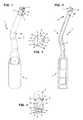
- dental or dental surgical ultrasonic tool 1comprises an elongated tool body 2, a connecting device 3 for releasably connecting the ultrasonic tool 1 to an ultrasonic source, a working section 4 which extends along a longitudinal axis 5 and which is formed on the basis of generated by the ultrasonic source and on the Connecting device 3 and the tool body 2 transmitted ultrasonic vibrations to penetrate into a bone to be treated, and a liquid line 6, which extends through the tool body 2 in the direction of the working portion 4 and in several, For example, two, 7A, 7B openings, which are provided for the exit of a fluid flowing in the liquid conduit 6 from the ultrasonic tool 1 ends.
- the elongate tool body 2has a bend 2A, so that the working section 4 or its longitudinal axis 5 are arranged at an angle to the connecting device 3.
- the elongated tool body 2further comprises a first end, on which the connection device 3 is provided, and a second end, to which the working section 4 connects.
- the working section 4has a distal end face 8 with several, for example five, cutting edges 9 and a lateral surface 10 extending from the distal end face 8 in the direction of the tool body 2.
- a lateral surface 10a plurality, for example five, channels 11 are provided to the liquid line.
- the channels 11extend in each case from the distal end face 8 in the direction of the tool body 2.
- the channelsare distributed uniformly on the lateral surface 10 at a distance from one another.
- the liquid line 6opens with its openings 7A, 7B on the lateral surface 10 of the working section 4.
- the openings 7A, 7Bare arranged in the channels 11, wherein in a channel 11 in each case only one opening 7A, 7B is located.
- only one of openings 7A, 7Bis provided in two channels 11 and the other three helical channels 11 have no opening 7A, 7B of the liquid line 6.
- the helical channels with the openings 7A, 7Bare preferably separated by at least one helical channel 11 without openings 7A, 7B.
- connection between the substantially centrally disposed in the tool body 2 liquid line 6 and the openings 7 A, 7 Bis accomplished by a plurality of line arms 6 A, wherein each of the openings 7 A, 7 B is connected via a separate line arm 6 A with the liquid line 6.
- the line arms 6Aare arranged at an angle to the liquid line 6.
- the channels 11 to the liquid lineextend helically around the longitudinal axis 5 of the working portion 4, with a rotation angle of approximately 70 °.
- the helical channels 11are separated by likewise helical webs 12.
- the channels 11are formed with respect to the webs 12 as depressions in the lateral surface 10.
- a plurality of, for example five, grooves 13 for conducting liquidare provided between the cutting edges 9 between the cutting edges 9 between the cutting edges 9 between the cutting edges 9 between the cutting edges 9 between the cutting edges 9 between the cutting edges 9 between the cutting edges 9 between the cutting edges 9 between the cutting edges 9 between the cutting edges 9 between the cutting edges 9 between the cutting edges 9 between the cutting edges 9 between the cutting edges 9 between the cutting edges 9 between the cutting edges 9 between the cutting edges 9 between the cutting edges 9 are provided a plurality of, for example five, grooves 13 for conducting liquid.
- the grooves 13are formed by projecting from the cutting edges 9, in the direction of the lateral surface 10 of the working portion 4 or the tool body 2 inclined surfaces 16. In each case a groove 13 is connected to a helically extending about the longitudinal axis 5 of the working portion 4 channel 11.
- the cutting edges 9 and the channels 13 for conducting liquidextend radially from a center of the distal end face 8.
- the cutting edges 9 and the grooves 13are furthermore inclined in the direction of a recess
- those helical channels 11, which have no openings 7A, 7B and which are part of the fluid path 15,are intended to lead fluid away from the distal end face 8 and / or the treatment site in the direction of the tool body 2.
Landscapes
- Health & Medical Sciences (AREA)
- Life Sciences & Earth Sciences (AREA)
- General Health & Medical Sciences (AREA)
- Veterinary Medicine (AREA)
- Oral & Maxillofacial Surgery (AREA)
- Public Health (AREA)
- Dentistry (AREA)
- Animal Behavior & Ethology (AREA)
- Epidemiology (AREA)
- Orthopedic Medicine & Surgery (AREA)
- Engineering & Computer Science (AREA)
- Water Supply & Treatment (AREA)
- Otolaryngology (AREA)
- Dental Tools And Instruments Or Auxiliary Dental Instruments (AREA)
- Surgical Instruments (AREA)
- Surgery (AREA)
- Nuclear Medicine, Radiotherapy & Molecular Imaging (AREA)
- Biomedical Technology (AREA)
- Heart & Thoracic Surgery (AREA)
- Medical Informatics (AREA)
- Molecular Biology (AREA)
Abstract
Translated fromGermanDescription
Translated fromGermanDie vorliegende Erfindung betrifft ein dentales oder dentalchirurgisches Ultraschallwerkzeug mit einem länglichen Werkzeugkörper, einer Anschlussvorrichtung zum lösbaren Anschluss an eine Ultraschallquelle, einer Flüssigkeitsleitung und einem Arbeitsabschnitt, der ausgebildet ist, mittels von der Ultraschallquelle übertragener Ultraschallschwingungen in einen zu behandelnden Knochen einzudringen.The present invention relates to a dental or dental surgical ultrasound tool having an elongated tool body, a connection device for detachable connection to an ultrasound source, a liquid line and a working portion which is designed to penetrate by means of ultrasonic vibrations transmitted from the ultrasound source in a bone to be treated.
Ein derartiges dentales oder dentalchirurgisches Ultraschallwerkzeug ist aus der Patentschrift
Der vorliegenden Erfindung liegt die Aufgabe zugrunde ein dentales oder dentalchirurgisches Ultraschallwerkzeug zu schaffen, dessen Verteilung der Kühlflüssigkeit, Kühlwirkung für die gesamte Spitze und dessen Handhabung verbessert ist.The present invention has for its object to provide a dental or dental surgical ultrasonic tool whose distribution of the cooling liquid, cooling effect for the entire tip and its handling is improved.
Diese Aufgabe wird gemäß der vorliegenden Erfindung durch ein dentales oder dentalchirurgisches Ultraschallwerkzeug mit den Merkmalen der Ansprüche 1 und 2 gelöst. Besonders vorteilhafte Ausführungsformen sind in den Unteransprüchen angeführt.This object is achieved according to the present invention by a dental or dental ultrasonic surgical tool with the features of
Gemäß einem ersten Ausführungsbeispiel umfasst das dentale oder dentalchirurgische Ultraschallwerkzeug einen länglichen Werkzeugkörper, eine Anschlussvorrichtung zum lösbaren Anschluss des Ultraschallwerkzeugs an eine Ultraschallquelle, wobei die Anschlussvorrichtung an einem ersten Ende des Werkzeugkörpers vorgesehen ist, einen an einem zweiten Ende des Werkzeugkörpers vorgesehenen Arbeitsabschnitt, der sich entlang einer Längsachse erstreckt und der ausgebildet ist, aufgrund der von der Ultraschallquelle erzeugten und über die Anschlussvorrichtung und den Werkzeugkörper übertragenen Ultraschallschwingungen in einen zu behandelnden Knochen einzudringen, und eine Flüssigkeitsleitung, die sich durch den Werkzeugkörper in Richtung des Arbeitsabschnitts erstreckt und in zumindest einer Öffnung endet, die zum Austritt einer in der Flüssigkeitsleitung fließenden Flüssigkeit aus dem Ultraschallwerkzeug vorgesehen ist. Der Arbeitsabschnitt weist eine distale Stirnfläche mit mehreren Schneidkanten und eine sich von der distalen Stirnfläche in Richtung des Werkzeugkörpers erstreckende Mantelfläche auf, wobei in der Mantelfläche zumindest ein Kanal zur Flüssigkeitsleitung vorgesehen ist, der sich von der distalen Stirnfläche in Richtung des Werkzeugkörpers erstreckt. Die zumindest eine Öffnung der Flüssigkeitsleitung ist an der Mantelfläche des Arbeitsabschnitts in dem zumindest einen Kanal zur Flüssigkeitsleitung oder unmittelbar anschließend an den zumindest einen Kanal zur Flüssigkeitsleitung angeordnet.According to a first embodiment, the dental or dental surgical ultrasound tool comprises an elongate tool body, a connection device for releasably connecting the ultrasound tool to an ultrasound source, the connection device being provided at a first end of the tool body, a working section provided at a second end of the tool body and extending along extends along a longitudinal axis and which is adapted to penetrate due to the ultrasonic vibrations generated by the ultrasonic source and transmitted via the connecting device and the tool body in a bone to be treated, and a liquid line which extends through the tool body in the direction of the working portion and terminating in at least one opening which is provided for the discharge of a liquid flowing in the liquid line from the ultrasonic tool. The working section has a distal end face with a plurality of cutting edges and a lateral surface extending from the distal end face in the direction of the tool body, wherein at least one channel is provided in the lateral surface for the liquid line, which extends from the distal end face in the direction of the tool body. The at least one opening of the liquid line is on the lateral surface of the working section in the at least one channel to the liquid line or arranged immediately adjacent to the at least one channel to the liquid line.
Das Vorsehen der zumindest einen Öffnung der Flüssigkeitsleitung, vorzugsweise von mehreren Öffnungen, an der Mantelfläche des Arbeitsabschnitts bewirkt eine bessere Verteilung der Kühlflüssigkeit auf dem gesamten Arbeitsabschnitt und damit eine stärkere Kühlwirkung, insbesondere wenn der Arbeitsabschnitt bereits in den Knochen eingedrungen ist und somit nicht nur an der distalen Stirnfläche, sondern auch an der seitlichen Mantelfläche des Arbeitsabschnitts eine Kühlung vorteilhaft ist. Durch die Anordnung der zumindest einen Öffnung der Flüssigkeitsleitung, vorzugsweise von mehreren Öffnungen, in dem oder unmittelbar anschließend an den zumindest einen Kanal zur Flüssigkeitsleitung wird sichergestellt, dass die Flüssigkeit zur distalen Stirnfläche und damit auch an die Behandlungsstelle gelangt, so dass auch diese beiden Bereiche ausreichend mit Flüssigkeit versorgt und gekühlt werden.The provision of the at least one opening of the liquid line, preferably of a plurality of openings, on the lateral surface of the working section causes a better distribution of the cooling liquid over the entire working section and thus a greater cooling effect, especially if the working section has already penetrated into the bone and thus not only the distal end face, but also on the lateral lateral surface of the working portion, a cooling is advantageous. The arrangement of the at least one opening of the liquid line, preferably of a plurality of openings, in or immediately adjacent to the at least one channel to the liquid line ensures that the liquid reaches the distal end face and thus also to the treatment site, so that these two areas be sufficiently supplied with liquid and cooled.
Der zumindest eine Kanal zur Flüssigkeitsleitung ist gemäß diesem ersten Ausführungsbeispiel entweder gerade, d.h. im Wesentlichen parallel zur Längsachse des Arbeitsabschnitts, oder wendelförmig um die Längsachse des Arbeitsabschnitts ausgebildet, so wie dies im Folgenden im Detail beschrieben ist.The at least one channel to the liquid line according to this first embodiment is either straight, i. formed substantially parallel to the longitudinal axis of the working portion, or helically around the longitudinal axis of the working portion, as described in detail below.
Gemäß einem zweiten Ausführungsbeispiel umfasst das dentale oder dentalchirurgische Ultraschallwerkzeug einen länglichen Werkzeugkörper, eine Anschlussvorrichtung zum lösbaren Anschluss des Ultraschallwerkzeugs an eine Ultraschallquelle, wobei die Anschlussvorrichtung an einem ersten Ende des Werkzeugkörpers vorgesehen ist, einen an einem zweiten Ende des Werkzeugkörpers vorgesehenen Arbeitsabschnitt, der sich entlang einer Längsachse erstreckt und der ausgebildet ist, aufgrund der von der Ultraschallquelle erzeugten und über die Anschlussvorrichtung und den Werkzeugkörper übertragenen Ultraschallschwingungen in einen zu behandelnden Knochen einzudringen, und eine Flüssigkeitsleitung, die sich durch den Werkzeugkörper in Richtung des Arbeitsabschnitts erstreckt und in zumindest einer Öffnung endet, die zum Austritt einer in der Flüssigkeitsleitung fließenden Flüssigkeit aus dem Ultraschallwerkzeug vorgesehen ist. Der Arbeitsabschnitt weist eine distale Stirnfläche mit mehreren Schneidkanten und eine sich von der distalen Stirnfläche in Richtung des Werkzeugkörpers erstreckende Mantelfläche auf, wobei in der Mantelfläche zumindest ein Kanal zur Flüssigkeitsleitung vorgesehen ist, der sich von der distalen Stirnfläche in Richtung des Werkzeugkörpers wendelförmig um die Längsachse des Arbeitsabschnitts erstreckt.According to a second embodiment, the dental or dental ultrasonic surgical tool comprises an elongate tool body, a connection device for releasably connecting the ultrasonic tool to an ultrasonic source, the connection device being provided at a first end of the tool body, a working section provided at a second end of the tool body and extending along extends along a longitudinal axis and which is adapted to penetrate due to the ultrasonic vibrations generated by the ultrasonic source and transmitted via the connecting device and the tool body in a bone to be treated, and a liquid line which extends through the tool body in the direction of the working portion and terminating in at least one opening which is provided for the discharge of a liquid flowing in the liquid line from the ultrasonic tool. The working section has a distal end face with a plurality of cutting edges and a lateral surface extending from the distal end face in the direction of the tool body, wherein at least one channel for the liquid line is provided in the lateral surface, which extends from the distal end face in the direction of the tool body helically about the longitudinal axis of the working section.
Durch die wendelförmige Ausbildung des zumindest einen Kanals zur Flüssigkeitsleitung wird insbesondere eine verbesserte Ausformung der Kavität im Knochen und eine erleichterte Handhabung des Ultraschallwerkzeugs erreicht: Da das Ultraschallwerkzeug während des Betriebs primär entlang der Längsachse des Arbeitsabschnitts vorwärts und zurück vibriert, entsteht über den gesamten Umfang des Knochens betrachtet durch das Vorsehen von zumindest einem wendelförmigen Kanal ein glatterer oder homogenerer Schnitt im Knochen (an der Seitenwand der Kavität) im Vergleich zu einem Kanal, der parallel zur Längsachse des Arbeitsabschnitts verläuft. Um eine gleichmäßige Formung der durch das Ultraschallwerkzeug in dem Knochen gebildeten Kavität zu erreichen, dreht der Anwender während des Vordringens des Ultraschallwerkzeugs in den Knochen das Ultraschallwerkzeug um die Längsachse des Arbeitsabschnitts. Dieses Drehen durch den Anwender wird ebenfalls erleichtert (es ist weniger "holprig"), da der Schnitt im Knochen durch den zumindest einen wendelförmigen Kanal glatter oder homogener ist.In particular, improved formation of the cavity in the bone and easier handling of the ultrasound tool are achieved by the helical design of the at least one channel for fluid conduction. Since the ultrasound tool primarily vibrates forward and back along the longitudinal axis of the working section during operation, it forms over the entire circumference of the Bone, by providing at least one helical channel, contemplates a smoother or more homogeneous cut in the bone (on the sidewall of the cavity) as compared to a channel that is parallel to the longitudinal axis of the working section. In order to achieve a uniform shaping of the cavity formed by the ultrasonic tool in the bone, the user rotates the ultrasonic tool about the longitudinal axis of the working section during the advance of the ultrasonic tool into the bone. This turning by the user is also facilitated (it is less "bumpy") because the cut in the bone is smoother or more homogeneous through the at least one helical channel.
Die im Folgenden genannten Eigenschaften und Merkmale beziehen sich jeweils auf beide im Vorstehenden genannte Ausführungsbeispiele:
- Das dentale oder dentalchirurgische Ultraschallwerkzeug ist vorzugsweise aus Metall gefertigt, insbesondere aus Stahl.
- The dental or dental surgical ultrasound tool is preferably made of metal, in particular of steel.
Der längliche Werkzeugkörper ist vorzugsweise zumindest an einem Abschnitt oder über seine gesamte Länge zylindrisch ausgebildet. Der längliche Werkzeugkörper weist vorzugsweise eine Biegung auf, so dass der Werkzeugkörper insbesondere zwei gewinkelt zueinander angeordnete Abschnitt aufweist. Der Winkel dieser beiden Abschnitte zueinander beträgt zum Beispiel zwischen 5° - 90°, bevorzugt zwischen 10° - 75°.The elongated tool body is preferably cylindrical at least at a portion or over its entire length. The elongate tool body preferably has a bend, so that the tool body in particular has two sections arranged at an angle to one another. The angle of these two sections to each other, for example, between 5 ° - 90 °, preferably between 10 ° - 75 °.
Die Anschlussvorrichtung ist zum lösbaren Anschluss des Ultraschallwerkzeugs an eine Ultraschallquelle und insbesondere auch zum lösbaren Anschluss an eine Flüssigkeitsquelle ausgebildet. Die Anschlussvorrichtung umfasst zum Beispiel ein rohrförmiges Element mit einer Innenbohrung und einem an der Wand der Innenbohrung vorgesehenen Innengewinde. Die Anschlussvorrichtung und das Ultraschallwerkzeug sind somit auf einen in der Innenbohrung aufnehmbaren Gewindestift aufschraubbar, der mit einer Ultraschallquelle und insbesondere einer Flüssigkeitsquelle verbunden ist. Der Gewindestift ist vorzugsweise Teil eines mit einer Hand haltbaren Handstücks.The connecting device is designed for the detachable connection of the ultrasonic tool to an ultrasound source and, in particular, for the detachable connection to a liquid source. The connection device comprises, for example, a tubular element with an inner bore and an inner thread provided on the wall of the inner bore. The connecting device and the ultrasonic tool are thus screwed onto a receivable in the inner bore threaded pin which is connected to an ultrasonic source and in particular a liquid source. The grub screw is preferably part of a hand-held handpiece.
Die Anschlussvorrichtung weist bevorzugt einen größeren Außendurchmesser als der Werkzeugkörper auf und ist insbesondere über einen sich verjüngenden Abschnitt, der vorzugsweise zumindest eine Ansatzfläche für ein Werkzeug zum Aufschrauben des Ultraschallwerkzeugs auf den Gewindestift aufweist, mit dem ersten Ende des Werkzeugkörpers verbunden.The connecting device preferably has a larger outer diameter than the tool body and is in particular a tapered portion, the preferably has at least one approach surface for a tool for screwing the ultrasonic tool on the threaded pin, connected to the first end of the tool body.
Der an einem zweiten Ende des Werkzeugkörpers vorgesehene Arbeitsabschnitt weist einen im Wesentlichen zylindrischen Außenumfang auf. Die Länge des Arbeitsabschnitts ist vorzugsweise um ein mehrfaches geringer als die Länge des Werkzeugkörpers. Die axiale Ausdehnung des Arbeitsabschnitts entlang seiner Längsachse erstreckt sich vorzugsweise von einem freien Ende des Ultraschallwerkzeugs, an dem insbesondere die distale Stirnfläche angeordnet ist, bis zumindest zu jenem Ende des zumindest einen Kanals zur Flüssigkeitsleitung, das dem anschließenden Werkzeugkörper zugewandt ist. Der Außendurchmesser des Arbeitsabschnitts ist vorzugsweise in etwa gleich groß oder größer wie der Außendurchmesser des Werkzeugkörpers. In letzterem Fall ist vorzugsweise ein sich verjüngender Übergangsabschnitt zum dem länglichen Werkzeugkörper vorgesehen, der wahlweise als Teil des Arbeitsabschnitts oder daran anschließend ausgebildet ist.The working section provided at a second end of the tool body has a substantially cylindrical outer circumference. The length of the working section is preferably several times less than the length of the tool body. The axial extent of the working section along its longitudinal axis preferably extends from a free end of the ultrasonic tool, on which in particular the distal end face is arranged, to at least that end of the at least one channel to the liquid line, which faces the adjoining tool body. The outer diameter of the working portion is preferably about the same size or larger than the outer diameter of the tool body. In the latter case, a tapered transition section is preferably provided for the elongated tool body, which is optionally formed as part of the working section or subsequently thereto.
Der Arbeitsabschnitt weist eine distale Stirnfläche mit mehreren Schneidkanten und eine sich von der distalen Stirnfläche in Richtung des Werkzeugkörpers erstreckende Mantelfläche auf, wobei in der, vorzugsweise im Wesentlichen zylindrisch ausgebildeten, Mantelfläche zumindest ein Kanal zur Flüssigkeitsleitung vorgesehen ist, der sich von der distalen Stirnfläche in Richtung des Werkzeugkörpers erstreckt.The working section has a distal end face with a plurality of cutting edges and a lateral surface extending from the distal end face in the direction of the tool body, wherein in the, preferably substantially cylindrical, shell surface at least one channel is provided for the liquid line extending from the distal end face in Direction of the tool body extends.
Je nach Ausführungsbeispiel ist der zumindest ein Kanal zur Flüssigkeitsleitung entweder gerade, d.h. im Wesentlichen parallel zur Längsachse des Arbeitsabschnitts, oder wendelförmig um die Längsachse des Arbeitsabschnitts ausgebildet. Der zumindest eine Kanal endet vorzugsweise an der distalen Stirnfläche und / oder ist mit dieser derart verbunden, dass in dem Kanal fließende Flüssigkeit auf die distale Stirnfläche und / oder auf die Behandlungsstelle übertragbar oder weiterleitbar ist und / oder Flüssigkeit von der distalen Stirnfläche und / oder der Behandlungsstelle in den zumindest ein Kanal übertreten kann.Depending on the embodiment, the at least one channel to the liquid line is either straight, i. substantially parallel to the longitudinal axis of the working section, or helically formed about the longitudinal axis of the working section. The at least one channel preferably terminates at the distal end face and / or is connected thereto in such a way that fluid flowing in the channel is transferable or transferable to the distal end face and / or to the treatment site and / or liquid from the distal end face and / or the treatment site in the at least one channel can pass.
Anschließend an den zumindest einen Kanal, insbesondere in Umfangsrichtung seitlich des Kanals, ist vorzugsweise zumindest ein Steg an dem Arbeitsabschnitt vorgesehen. Bei Vorhandensein mehrerer Kanäle auf dem Arbeitsabschnitt trennt jeweils ein Steg zwei Kanäle voneinander. Der Verlauf des zumindest eine Stegs entspricht vorzugsweise im Wesentlichen dem des zumindest einen Kanals, d.h. der zumindest eine Steg ist entweder im Wesentlichen parallel zur Längsachse des Arbeitsabschnitts oder wendelförmig um die Längsachse des Arbeitsabschnitts ausgebildet. Entsprechend endet der zumindest eine Steg vorzugsweise an der distalen Stirnfläche oder bildet mit der distalen Stirnfläche eine gemeinsame Kante. Besonders bevorzugt schließt an das freie, distale Ende des zumindest einen Stegs zumindest eine Schneidkante der distalen Stirnfläche an. Vorzugsweise ist der zumindest eine Steg erhöht gegenüber dem zumindest einen Kanal oder der zumindest eine Kanal ist als Vertiefung gegenüber dem zumindest einen Steg geformt.Subsequent to the at least one channel, in particular in the circumferential direction laterally of the channel, at least one web is preferably provided on the working section. If there are several channels on the working section, one bar separates two channels from each other. The course of the at least one web preferably corresponds substantially to that of the at least one channel, ie the at least one web is either substantially parallel to the longitudinal axis of the working portion or helically formed about the longitudinal axis of the working portion. Accordingly, the at least one web preferably terminates at the distal end face or forms a common edge with the distal end face. Particularly preferably, at least one cutting edge of the distal end face adjoins the free, distal end of the at least one web. Preferably, the at least one web is increased relative to the at least one channel, or the at least one channel is formed as a depression relative to the at least one web.
Vorzugsweise erstrecken sich die Schneidkanten radial von einem Mittelpunkt der distalen Stirnfläche in Richtung der Peripherie der distalen Stirnfläche oder in Richtung der Mantelfläche. Vorzugsweise bildet jede Schneidkante einen Grat oder Kamm zweier von der Schneidkante in Richtung der distalen Stirnfläche oder des Werkzeugkörpers geneigter Flächen. Vorzugsweise kontaktiert jeder dieser geneigten Flächen an ihrer tiefsten Stelle eine weitere geneigte Fläche der nächstgelegenen Schneidkante, wodurch zwischen zwei benachbarten Schneidkanten jeweils eine Vertiefung oder eine Rinne gebildet ist. Diese Vertiefung oder Rinne ist vorzugsweise zur Leitung von Flüssigkeit vorgesehen, so wie dies im Nachstehenden noch im Detail beschrieben ist.Preferably, the cutting edges extend radially from a center of the distal end surface toward the periphery of the distal end surface or in the direction of the lateral surface. Preferably, each cutting edge forms a ridge or comb of two surfaces inclined from the cutting edge in the direction of the distal end surface or of the tool body. Preferably, each of these inclined surfaces contacted at its lowest point another inclined surface of the nearest cutting edge, whereby between two adjacent cutting edges each have a recess or a groove is formed. This depression or channel is preferably provided for conducting liquid, as will be described in detail below.
Vorzugsweise ist der freie oder distale Endabschnitt des zumindest einen Stegs an einer Umfangskante der distalen Stirnfläche zu einem überwiegenden Teil mit einer Schneidkante und deren geneigten Flächen verbunden. Vorzugsweise ist der zumindest eine Kanal an einer Umfangskante der distalen Stirnfläche flüssigkeitsübertragend mit der Vertiefung oder Rinne verbunden.Preferably, the free or distal end portion of the at least one ridge at a peripheral edge of the distal end face is connected for the most part with a cutting edge and its inclined surfaces. Preferably, the at least one channel is connected in a fluid-transmitting manner with the depression or groove at a peripheral edge of the distal end face.
Die Flüssigkeitsleitung, die sich durch den Werkzeugkörper in Richtung des Arbeitsabschnitts erstreckt, ist vorzugsweise als zylindrische Bohrung in dem Werkzeugkörper ausgebildet. Die Flüssigkeitsleitung endet in zumindest einer Öffnung, die zum Austritt einer in der Flüssigkeitsleitung fließenden Flüssigkeit aus dem Ultraschallwerkzeug vorgesehen ist. Die Flüssigkeitsleitung ist mit der Anschlussvorrichtung, insbesondere mit deren Innenbohrung, verbunden oder setzt sich in der Innenbohrung der Anschlussvorrichtung fort. Falls die Flüssigkeitsleitung in mehreren Öffnungen zum Austritt einer Flüssigkeit endet, so verzweigt sich die Flüssigkeitsleitung, insbesondere im Bereich des Arbeitsabschnitts oder unmittelbar daran anschließend, vorzugsweise in mehrere Leitungsarme zur Versorgung der mehreren Öffnungen.The liquid conduit which extends through the tool body in the direction of the working portion is preferably formed as a cylindrical bore in the tool body. The liquid line ends in at least one opening which is provided for the exit of a liquid flowing in the liquid line from the ultrasonic tool. The liquid line is connected to the connection device, in particular with its inner bore, or continues in the inner bore of the connection device. If the liquid line terminates in a plurality of openings for the discharge of a liquid, the liquid line branches, in particular in the region of the working section or immediately thereafter, preferably into a plurality of line arms for supplying the plurality of openings.
Die zumindest eine Öffnung, die zum Austritt einer in der Flüssigkeitsleitung fließenden Flüssigkeit aus dem Ultraschallwerkzeug vorgesehen ist, ist wahlweise an der Mantelfläche des Arbeitsabschnitts oder an der distalen Stirnfläche angeordnet. Vorzugsweise ist die zumindest eine Öffnung an der Mantelfläche in dem zumindest einen Kanal zur Flüssigkeitsleitung oder unmittelbar anschließend an den zumindest einen Kanal zur Flüssigkeitsleitung oder im Zentrum der distalen Stirnfläche angeordnet.The at least one opening, which is provided for the exit of a liquid flowing in the liquid line from the ultrasonic tool, is optionally arranged on the lateral surface of the working section or on the distal end face. Preferably, the at least one opening is arranged on the lateral surface in the at least one channel to the liquid line or immediately adjacent to the at least one channel to the liquid line or in the center of the distal end face.
Vorzugsweise sind mehrere Öffnungen, zum Beispiel zwei, drei oder vier Öffnungen, zum Austritt einer in der Flüssigkeitsleitung fließenden Flüssigkeit aus dem Ultraschallwerkzeug vorgesehen. Diese Öffnungen können wahlweise alle an der Mantelfläche des Arbeitsabschnitts angeordnet sein, insbesondere in mehreren Kanälen zur Flüssigkeitsleitung oder unmittelbar anschließend an diese Kanäle. Durch das Vorsehen mehrerer Öffnungen der Flüssigkeitsleitung an der Mantelfläche des Arbeitsabschnitts wird insbesondere eine verbesserte Verteilung der Flüssigkeit an der Mantelfläche oder dem Umfang des Ultraschallwerkzeugs erreicht. Alternativ ist zumindest eine Öffnung, bevorzugt sind mehrere Öffnungen, an der Mantelfläche des Arbeitsabschnitts angeordnet, insbesondere in einem Kanal oder mehreren Kanälen zur Flüssigkeitsleitung oder unmittelbar anschließend diesen Kanal oder diese Kanäle, und es ist zumindest eine (weitere) Öffnung der Flüssigkeitsleitung an der distalen Stirnfläche vorgesehen. Damit wird eine besonderes gute Versorgung des gesamten Arbeitsabschnitts einschließlich der distalen Stirnfläche mit Flüssigkeit und eine besonders gute Kühlleistung erzielt.Preferably, a plurality of openings, for example two, three or four openings, are provided for the exit of a liquid flowing in the liquid line from the ultrasonic tool. Optionally, these openings can all be arranged on the lateral surface of the working section, in particular in a plurality of channels for the liquid line or immediately following these channels. By providing a plurality of openings of the liquid line on the lateral surface of the working section in particular an improved distribution of the liquid is achieved on the lateral surface or the circumference of the ultrasonic tool. Alternatively, at least one opening, preferably a plurality of openings, are arranged on the lateral surface of the working section, in particular in one channel or several channels for the liquid line or immediately thereafter this channel or channels, and there is at least one (further) opening of the liquid line at the distal Face provided. This achieves a particularly good supply of the entire working section including the distal end face with liquid and a particularly good cooling performance.
Vorzugsweise sind mehrere, sich insbesondere wendelförmig um die Längsachse des Arbeitsabschnitts erstreckende, Kanäle und mehrere Öffnungen der Flüssigkeitsleitung vorgesehen, wobei in oder an einem Kanal jeweils nur eine Öffnung angeordnet ist.Preferably, several, in particular helically extending around the longitudinal axis of the working portion, channels and a plurality of openings of the liquid line are provided, wherein in or on a channel in each case only one opening is arranged.
Vorzugsweise ist zumindest in oder an einem, sich insbesondere wendelförmig um die Längsachse des Arbeitsabschnitts erstreckenden, Kanal keine Öffnung der Flüssigkeitsleitung vorgesehen. Insbesondere ist die Anzahl der Öffnungen der Flüssigkeitsleitung, die in oder an einem, sich insbesondere wendelförmig um die Längsachse des Arbeitsabschnitts erstreckenden, Kanal angeordnet sind, geringer ist als die Anzahl der (aller) Kanäle, so dass zumindest in und an einem Kanal keine Öffnung der Flüssigkeitsleitung vorgesehen ist. Dieser zumindest eine, sich insbesondere wendelförmig um die Längsachse des Arbeitsabschnitts erstreckenden, Kanal ohne Öffnungen der Flüssigkeitsleitung ist insbesondere dazu ausgebildet ist, Flüssigkeit von der distalen Stirnfläche und / oder der Behandlungsstelle wegzuleiten.Preferably, no opening of the liquid line is provided at least in or at one, in particular helically extending around the longitudinal axis of the working portion, channel. In particular, the number of openings of the liquid line, which are arranged in or on one, in particular helically extending around the longitudinal axis of the working portion, channel, is less than the number of (all) channels, so that at least in and on a channel no opening the liquid line is provided. This at least one, in particular helically extending around the longitudinal axis of the working portion, channel without openings of the liquid line is in particular designed to conduct away fluid from the distal end face and / or the treatment site.
Vorzugsweise weist der zumindest eine, sich insbesondere wendelförmig um die Längsachse des Arbeitsabschnitts erstreckende, Kanal eine in Richtung der distalen Stirnfläche zunehmende Tiefe auf. Die Zunahme der Tiefe in Richtung der distalen Stirnfläche beträgt (ausgehend von der geringsten Tiefe) zum Beispiel zwischen 4% und 25%, vorzugsweise zwischen 5% und 15%. Die zunehmende Tiefe des zumindest einen Kanals bewirkt ein bevorzugtes Fließen der Flüssigkeit in dem Kanal, insbesondere der aus der Öffnungen der Flüssigkeitsleitung ausgetretenen und durch den Kanal weitergeleiteten Flüssigkeit, in Richtung der distalen Stirnfläche. Vorzugsweise weist zumindest ein Kanal eine konstante Tiefe auf, insbesondere ein Kanal, der dazu ausgebildet ist, Flüssigkeit von der distalen Stirnfläche und / oder der Behandlungsstelle wegzuleiten, zum Beispiel ein im Vorstehenden genannter Kanal ohne Öffnungen der Flüssigkeitsleitung.The at least one channel, which extends in particular helically around the longitudinal axis of the working section, preferably has a depth which increases in the direction of the distal end face. For example, the increase in depth in the direction of the distal end face (starting from the lowest depth) is between 4% and 25%, preferably between 5% and 15%. The increasing depth of the at least one channel causes a preferential flow of the liquid in the channel, in particular the liquid which has leaked out of the openings of the liquid line and is passed on through the channel, in the direction of the distal end face. Preferably, at least one channel has a constant depth, in particular a channel, which is designed to conduct fluid away from the distal end face and / or the treatment site, for example a channel mentioned above with no openings of the liquid line.
Vorzugsweise beträgt die Steigung des zumindest einen sich wendelförmig um die Längsachse des Arbeitsabschnitts erstreckende Kanals etwa 5 mm - 50 mm, vorzugsweise etwa 15 mm - 25 mm. Die Steigung definiert dabei die Länge des Wegs oder des wendelförmigen Kanals, der durch eine vollständige Umdrehung (um 360°) des Arbeitsabschnitts, insbesondere des wendelförmigen Kanals, zurückgelegt wird. Der kegelige Gewindeanstieg oder die Verjüngung des wendelförmigen Kanals in Richtung der distalen Stirnfläche beträgt vorzugsweise in etwa 3% - 25%, insbesondere in etwa 5% - 15%, vorzugsweise zwischen 8 % - 9 %.Preferably, the pitch of the at least one helically extending around the longitudinal axis of the working portion channel is about 5 mm - 50 mm, preferably about 15 mm - 25 mm. The slope defines the length of the path or the helical channel, which is covered by a complete revolution (by 360 °) of the working section, in particular the helical channel. The conical thread increase or the taper of the helical channel in the direction of the distal end face is preferably in about 3% -25%, in particular in about 5% -15%, preferably between 8% -9%.
Vorzugsweise windet der zumindest eine wendelförmige Kanal sich mit einem Drehwinkel im Bereich zwischen 45° und 180° um die Längsachse des Arbeitsabschnitts. Der zumindest eine wendelförmige Kanal windet sich zum Beispiel mit in etwa einer 1/8 bis ¼-Drehung um die Längsachse des Arbeitsabschnitts.Preferably, the at least one helical channel winds at a rotational angle in the range between 45 ° and 180 ° about the longitudinal axis of the working portion. The at least one helical channel winds, for example, about 1/8 to ¼ rotation about the longitudinal axis of the working section.
Vorzugsweise ist die zumindest eine Öffnung der Flüssigkeitsleitung in jener Hälfte des zumindest einen, sich insbesondere wendelförmig um die Längsachse des Arbeitsabschnitts erstreckenden, Kanals vorgesehen, die näher zur distalen Stirnfläche angeordnet ist. Damit ist eine optimale Versorgung und Kühlung der Mantelfläche des Arbeitsabschnitts, der daran angrenzenden Knochenschicht, der distalen Stirnfläche und der damit bearbeiteten Knochenfläche erzielbar.Preferably, the at least one opening of the liquid line is provided in that half of the at least one, in particular helically extending around the longitudinal axis of the working portion, channel which is arranged closer to the distal end face. For an optimal supply and cooling of the lateral surface of the working portion, the adjoining bone layer, the distal end face and the processed bone surface can be achieved.
Wie im Vorstehenden bereits beschrieben sind an der distalen Stirnfläche, zwischen den Schneidkanten Rinnen zur Leitung von Flüssigkeit vorgesehen, die mit dem zumindest einen, sich insbesondere wendelförmig um die Längsachse des Arbeitsabschnitts erstreckenden, Kanal verbunden sind oder in diesen münden. Die Rinnen sind insbesondere durch von den Schneidkanten entspringende, in Richtung der Mantelfläche des Arbeitsabschnitts oder des Werkzeugkörpers geneigte Flächen gebildet. Durch die Rinnen ist eine optimale Leitung der Flüssigkeit von der zumindest einen Öffnung der Flüssigkeitsleitung durch den zumindest einen Kanal bis an die distale Stirnfläche und / oder die Behandlungsstelle und / oder eine optimale Ableitung der Flüssigkeit und insbesondere darin enthaltener Partikel, zum Beispiel durch die Schneidkanten abgetragener Knochenpartikel, von der distalen Stirnfläche und / oder der Behandlungsstelle weg (in Richtung des Werkzeugkörpers) möglich.As already described above, grooves for the conduction of liquid are provided on the distal end face, between the cutting edges, which are connected to the at least one, in particular helically extending around the longitudinal axis of the working portion, channel or open into this. The grooves are formed, in particular, by surfaces projecting from the cutting edges and inclined in the direction of the lateral surface of the working section or of the tool body. Through the grooves, an optimal conduction of the liquid from the at least one opening of the liquid line through the at least one channel to the distal end face and / or the treatment site and / or an optimal discharge of the liquid and in particular Particles contained therein, for example, by the cutting edges of ablated bone particles, from the distal end face and / or the treatment point away (in the direction of the tool body) possible.
Vorzugsweise erstrecken sich die Rinnen zur Leitung von Flüssigkeit, insbesondere entsprechend den Schneidkanten, radial von einem Mittelpunkt der distalen Stirnfläche in Richtung des Umfangs der distalen Stirnfläche. Die distale Stirnfläche ist damit sternförmig mit von ihrem Mittelpunkt ausgehenden, abwechselnd angeordneten Rinnen und Schneidkanten ausgebildet. Vorzugsweise sind die Schneidkanten und die Rinnen zur Leitung von Flüssigkeit in Richtung einer zentral in der distalen Stirnfläche angeordneten Vertiefung geneigt. Besonders bevorzugt ist in dem Mittelpunkt oder der Vertiefung der distalen Stirnfläche eine Öffnung der Flüssigkeitsleitung vorgesehen.Preferably, the grooves for guiding liquid, in particular corresponding to the cutting edges, extend radially from a center of the distal end face in the direction of the circumference of the distal end face. The distal end face is thus formed in a star shape with outgoing from its center, alternately arranged grooves and cutting edges. Preferably, the cutting edges and the channels for guiding liquid are inclined in the direction of a recess arranged centrally in the distal end face. Particularly preferably, an opening of the liquid line is provided in the center or the depression of the distal end face.
Vorzugsweise ist ein an dem Ultraschallwerkzeug ausgebildeter Flüssigkeitspfad vorgesehen, der folgende, im Vorstehenden genannten Elemente umfasst: die Flüssigkeitsleitung, die zumindest eine Öffnung zum Austritt einer in der Flüssigkeitsleitung fließenden Flüssigkeit aus dem Ultraschallwerkzeug, den zumindest einen, sich insbesondere wendelförmig um die Längsachse des Arbeitsabschnitts erstreckenden, Kanal und die Rinnen zur Leitung von Flüssigkeit an der distalen Stirnfläche. Der Flüssigkeitspfad ist insbesondere dazu ausgebildet, eine Flüssigkeit durch diese genannten Elemente des Ultraschallwerkzeugs an die distale Stirnfläche und / oder eine Behandlungsstelle zu leiten, wodurch eine ausgezeichnete Kühlung des gesamten Arbeitsabschnitts und Verteilung der Flüssigkeit auf den zu bearbeitenden Knochen und den Arbeitsabschnitt möglich ist.Preferably, a liquid path formed on the ultrasonic tool is provided, which comprises the following elements: the liquid line, the at least one opening for the exit of a liquid flowing in the liquid line from the ultrasonic tool, the at least one, in particular helically around the longitudinal axis of the working portion extending channel and the channels for conducting fluid at the distal end face. In particular, the fluid path is adapted to direct a fluid through said elements of the ultrasound tool to the distal end surface and / or a treatment site, thereby allowing excellent cooling of the entire working section and distribution of the fluid to the bone being processed and the working section.
Besonders bevorzugt umfasst der Flüssigkeitspfad des Weiteren zumindest einen, sich insbesondere wendelförmig um die Längsachse des Arbeitsabschnitts erstreckenden, Kanal, der ausgebildet ist, Flüssigkeit von der distalen Stirnfläche und / oder der Behandlungsstelle wegzuleiten. In oder an diesem zumindest eine Kanal zum Ableiten der Flüssigkeit ist insbesondere keine Öffnung zum Austritt einer in der Flüssigkeitsleitung fließenden Flüssigkeit vorgesehen. Von der Flüssigkeit wird insbesondere auch durch die Schneidelemente abgetragenes Material mitgenommen und von der Behandlungsstelle entfernt, wodurch die Abtragungswirkung der Schneidelemente verbessert wird.Particularly preferably, the fluid path further comprises at least one, in particular helically extending around the longitudinal axis of the working portion, channel, which is adapted to conduct liquid away from the distal end face and / or the treatment site. In or on this at least one channel for discharging the liquid, in particular, no opening is provided for the exit of a liquid flowing in the liquid line. In particular, material removed by the cutting material is also taken away from the liquid by the liquid and removed from the treatment site, whereby the removal effect of the cutting elements is improved.
Vorzugsweise ist an zumindest einem Abschnitt des Ultraschallwerkzeugs, insbesondere an dem Arbeitsabschnitt und / oder an zumindest einem Teil des Körpers, eine Beschichtung zum Schutz vor Korrosion vorgesehen, zum Beispiel eine Titan-Nitrid-Beschichtung.Preferably, at least a portion of the ultrasonic tool, in particular on the working portion and / or on at least a part of the body, a coating for protection against corrosion is provided, for example, a titanium-nitride coating.
Eine dentale oder dentalchirurgische Behandlungsvorrichtung umfasst ein im Vorstehenden beschriebenes Ultraschallwerkzeug und eine Ultraschallquelle zur Erzeugung von Ultraschallschwingungen, die mit dem Ultraschallwerkzeug verbindbar ist, so dass die von der Ultraschallquelle erzeugten Ultraschallschwingungen auf das Ultraschallwerkzeug übertragbar sind. Die Ultraschallquelle ist zum Beispiel als Piezoschwinger oder als magnetostriktiver Schwinger ausgebildet. Die Ultraschallquelle ist bevorzugt in einem dentalen oder dentalchirurgischen Handstück angeordnet.A dental or dental surgical treatment device comprises an ultrasonic tool described above and an ultrasonic source for generating ultrasonic vibrations connectable to the ultrasonic tool so that the ultrasonic vibrations generated by the ultrasonic source are transferable to the ultrasonic tool. The ultrasound source is designed, for example, as a piezo oscillator or as a magnetostrictive oscillator. The ultrasound source is preferably arranged in a dental or dental surgical handpiece.
Die Behandlungsvorrichtung oder das Handstück umfassen bevorzugt zumindest ein weiteres der folgenden Bauteile: Eine Werkzeugverbindungsvorrichtung zur lösbaren Verbindung mit dem Ultraschallwerkzeug, die insbesondere den im Vorstehenden beschriebenen Gewindestift umfasst; eine elektrische oder elektronische Steuerung zum Betrieb der Behandlungsvorrichtung oder des Handstücks, insbesondere der Ultraschallquelle; einen Schwingungsüberträger oder eine Sonotrode zum Übertragen der von der Ultraschallquelle erzeugten Ultraschallschwingungen auf das Ultraschallwerkzeug; eine Beleuchtungsvorrichtung, vorzugsweise mit LEDs, insbesondere mit einer ringförmigen Lichtabgabefläche an dem im Betrieb der Behandlungsstelle zugewandten Ende, wobei die ringförmige Lichtabgabefläche das Ultraschallwerkzeug umgibt; zumindest eine Leitung zum Übertragen der Flüssigkeit von einer Flüssigkeitsquelle an das Ultraschallwerkzeug.The treatment device or the handpiece preferably comprises at least one of the following components: A tool connection device for detachable connection to the ultrasonic tool, which in particular comprises the threaded pin described above; an electrical or electronic control for operating the treatment device or the handpiece, in particular the ultrasonic source; a vibration transmitter or a sonotrode for transmitting the ultrasonic vibrations generated by the ultrasonic source to the ultrasonic tool; a lighting device, preferably with LEDs, in particular with an annular light-emitting surface on the end facing in operation of the treatment point, wherein the annular light-emitting surface surrounds the ultrasonic tool; at least one conduit for transferring the liquid from a liquid source to the ultrasonic tool.
Die Erfindung wird nachfolgend anhand eines bevorzugten Ausführungsbeispiels und Bezug nehmend auf die beigefügten Zeichnungen erläutert. Es zeigt die
Figur 1 eine perspektivische Ansicht eines dentalen oder dentalchirurgischen Ultraschallwerkzeugs;Figur 2Figur 1 ;Figur 3Figur 1 ;Figur 4Figur 1 .
FIG. 1 a perspective view of a dental or dental surgical ultrasound tool;FIG. 2 a sectional view through the ultrasonic tool ofFIG. 1 ;FIG. 3 an enlarged view of the distal end portion of the ultrasonic tool ofFIG. 1 ;FIG. 4 a front view of the working portion of the ultrasonic tool ofFIG. 1 ,
Das in den
Zur Erleichterung der Handhabung des Ultraschallwerkzeugs 1 weist der längliche Werkzeugkörper 2 eine Biegung 2A auf, so dass der Arbeitsabschnitt 4 oder dessen Längsachse 5 gewinkelt zur Anschlussvorrichtung 3 angeordnet sind. Der längliche Werkzeugkörper 2 umfasst des Weiteren ein erstes Ende, an dem die Anschlussvorrichtung 3 vorgesehen ist, und ein zweites Ende, an das der Arbeitsabschnitt 4 anschließt.To facilitate the handling of the ultrasonic tool 1, the
Der Arbeitsabschnitt 4 weist eine distale Stirnfläche 8 mit mehreren, zum Beispiel fünf, Schneidkanten 9 und eine sich von der distalen Stirnfläche 8 in Richtung des Werkzeugkörpers 2 erstreckende Mantelfläche 10 auf. In der Mantelfläche 10 sind mehrere, zum Beispiel fünf, Kanäle 11 zur Flüssigkeitsleitung vorgesehen. Die Kanäle 11 erstrecken sich jeweils von der distalen Stirnfläche 8 in Richtung des Werkzeugkörpers 2. Die Kanäle sind gleichmäßig voneinander beabstandet auf der Mantelfläche 10 verteilt.The working
Die Flüssigkeitsleitung 6 mündet mit ihren Öffnungen 7A, 7B an der Mantelfläche 10 des Arbeitsabschnitts 4. Die Öffnungen 7A, 7B sind in den Kanälen 11 angeordnet, wobei sich in einem Kanal 11 jeweils nur eine Öffnung 7A, 7B befindet. Wie insbesondere aus den
Die Verbindung zwischen der im Wesentlichen zentral in dem Werkzeugkörper 2 angeordneten Flüssigkeitsleitung 6 und den Öffnungen 7A, 7B ist durch mehrere Leitungsarme 6A bewerkstelligt, wobei jede der Öffnungen 7A, 7B über einen eigenen Leitungsarm 6A mit der Flüssigkeitsleitung 6 verbunden ist. Die Leitungsarme 6A sind gewinkelt zur Flüssigkeitsleitung 6 angeordnet.The connection between the substantially centrally disposed in the
Die Kanäle 11 zur Flüssigkeitsleitung erstrecken sich wendelförmig um die Längsachse 5 des Arbeitsabschnitts 4, mit einem Drehwinkel von in etwa 70°. Die wendelförmigen Kanäle 11 sind durch ebenfalls wendelförmige Stege 12 voneinander getrennt. Die Kanäle 11 sind in Bezug auf die Stege 12 als Vertiefungen in die Mantelfläche 10 ausgebildet.The
An der distalen Stirnfläche 8, zwischen den Schneidkanten 9 sind mehrere, zum Beispiel fünf, Rinnen 13 zur Leitung von Flüssigkeit vorgesehen. Die Rinnen 13 sind durch von den Schneidkanten 9 entspringende, in Richtung der Mantelfläche 10 des Arbeitsabschnitts 4 oder des Werkzeugkörpers 2 geneigte Flächen 16 gebildet. Jeweils eine Rinne 13 ist mit einem sich wendelförmig um die Längsachse 5 des Arbeitsabschnitts 4 erstreckenden Kanal 11 verbunden. Die Schneidkanten 9 und die Rinnen 13 zur Leitung von Flüssigkeit erstrecken sich radial von einem Mittelpunkt der distalen Stirnfläche 8. Die Schneidkanten 9 und die Rinnen 13 sind des Weiteren in Richtung einer zentral um den Mittelpunkt der distalen Stirnfläche 8 angeordneten Vertiefung 14 geneigt.At the
Die Flüssigkeitsleitung 6, die beiden Öffnungen 7A, 7B zum Austritt einer in der Flüssigkeitsleitung 6 fließenden Flüssigkeit, die sich wendelförmig um die Längsachse 5 des Arbeitsabschnitts 4 erstreckenden Kanäle 11, insbesondere jene Kanäle 11, in oder an denen die Öffnungen 7A, 7B angeordnet sind, und die Rinnen 13 an der distalen Stirnfläche 8 bilden zusammen einen Flüssigkeitspfad 15, um eine Flüssigkeit von der Flüssigkeitsleitung 6 bis an die distale Stirnfläche 8 und / oder eine Behandlungsstelle zu leiten und den Arbeitsabschnitt 4 und die Behandlungsstelle zu kühlen. Insbesondere jene wendelförmigen Kanäle 11, die keine Öffnungen 7A, 7B aufweisen und die Teil des Flüssigkeitspfads 15 sind, sind dazu vorgesehen, Flüssigkeit von der distalen Stirnfläche 8 und / oder der Behandlungsstelle in Richtung des Werkzeugkörpers 2 wegzuleiten.The
Die Erfindung ist nicht auf das beschriebene Ausführungsbeispiele beschränkt, sondern umfasst alle Ausführungen, die das prinzipielle, sinngemäße Funktionsprinzip der Erfindung gemäß den Ansprüchen anwenden oder beinhalten. Des Weiteren ist jedes beschriebene oder dargestellte Merkmal mit jedem anderen beschriebenen oder dargestellten Merkmal kombinierbar.The invention is not limited to the exemplary embodiments described, but encompasses all embodiments which apply or include the basic, analogous operating principle of the invention according to the claims. Furthermore, any feature described or illustrated may be combined with any other feature described or illustrated.
Claims (15)
Translated fromGermanmehrere, sich insbesondere wendelförmig um die Längsachse (5) des Arbeitsabschnitts (4) erstreckende, Kanäle (11), diedurch, insbesondere wendelförmige, Stege (12) voneinander getrennt sind.Dental or dental surgical ultrasound tool (1) according to claim 1 or 2,characterized by
a plurality of, in particular helically around the longitudinal axis (5) of the working portion (4) extending channels (11) which areseparated by , in particular helical, webs (12).
mehrere, sich insbesondere wendelförmig um die Längsachse (5) des Arbeitsabschnitts (4) erstreckende, Kanäle (11) und mehrere Öffnungen (7A, 7B) der Flüssigkeitsleitung (6), wobei in oder an einem Kanal (11) jeweils nur eine Öffnung (7A, 7B) angeordnet ist.Dental or dental surgical ultrasound tool (1) according to one of claims 1-3,characterized by
a plurality of channels (11) extending in particular helically around the longitudinal axis (5) of the working section (4) and a plurality of openings (7A, 7B) of the liquid line (6), wherein in or on a channel (11) only one opening ( 7A, 7B) is arranged.
zumindest in oder an einem, sich insbesondere wendelförmig um die Längsachse (5) des Arbeitsabschnitts (4) erstreckenden, Kanal (11) keine Öffnung (7A, 7B) der Flüssigkeitsleitung (6) vorgesehen ist.Dental or dental surgical ultrasound tool (1) according to one of the preceding claims,characterized in that
at least in or on one, in particular helically around the longitudinal axis (5) of the working section (4) extending, channel (11) no opening (7A, 7B) of the liquid line (6) is provided.
der zumindest eine, sich insbesondere wendelförmig um die Längsachse (5) des Arbeitsabschnitts (4) erstreckende, Kanal (11) eine in Richtung der distalen Stirnfläche (8) zunehmende Tiefe aufweist.Dental or dental surgical ultrasound tool (1) according to one of the preceding claims,characterized in that
the at least one, in particular helically around the longitudinal axis (5) of the working portion (4) extending, channel (11) in the direction of the distal end face (8) increasing depth.
die Steigung des zumindest einen sich wendelförmig um die Längsachse (5) des Arbeitsabschnitts (4) erstreckende Kanals (11) etwa 5 mm - 50 mm beträgt.Dental or dental surgical ultrasound tool (1) according to one of claims 2-6,characterized in that
the pitch of the at least one helically around the longitudinal axis (5) of the working portion (4) extending channel (11) is about 5 mm - 50 mm.
der zumindest eine sich wendelförmig um die Längsachse (5) des Arbeitsabschnitts (4) erstreckende Kanal (11) sich mit einem Drehwinkel im Bereich zwischen 45° und 180° um die Längsachse (5) windet.Dental or dental surgical ultrasound tool (1) according to one of claims 2-7,characterized in that
the at least one helically around the longitudinal axis (5) of the working portion (4) extending channel (11) winds at a rotational angle in the range between 45 ° and 180 ° about the longitudinal axis (5).
die zumindest eine Öffnung (7A, 7B) der Flüssigkeitsleitung (6) in jener Hälfte des zumindest einen, sich insbesondere wendelförmig um die Längsachse (5) des Arbeitsabschnitts (4) erstreckenden, Kanals (11) vorgesehen ist, die näher zur distalen Stirnfläche (8) angeordnet ist.Dental or dental surgical ultrasound tool (1) according to one of claims 1-8,characterized in that
the at least one opening (7A, 7B) of the liquid line (6) is provided in that half of the at least one channel (11) extending in particular helically around the longitudinal axis (5) of the working section (4), which is closer to the distal end face (Fig. 8) is arranged.
an der distalen Stirnfläche (8), zwischen den Schneidkanten (9) Rinnen (13) zur Leitung von Flüssigkeit vorgesehen sind, die mit dem zumindest einen, sich insbesondere wendelförmig um die Längsachse (5) des Arbeitsabschnitts (4) erstreckenden, Kanal (11) verbunden sind oder in diesen münden.Dental or dental surgical ultrasound tool (1) according to any one of claims 1-9,characterized in that
on the distal end face (8), between the cutting edges (9) are provided channels (13) for conducting liquid, which are connected to the at least one channel (11) extending in particular helically around the longitudinal axis (5) of the working section (4) ) are connected or result in these.
die Schneidkanten (9) und die Rinnen (13) zur Leitung von Flüssigkeit sich radial von einem Mittelpunkt der distalen Stirnfläche (8) erstrecken.Dental or dental surgical ultrasound tool (1) according to claim 10,characterized in that
the cutting edges (9) and the liquid flow channels (13) extend radially from a center of the distal end surface (8).
die Schneidkanten (9) und die Rinnen (13) zur Leitung von Flüssigkeit in Richtung einer zentral in der distalen Stirnfläche (8) angeordneten Vertiefung (14) geneigt sind.Dental or dental surgical ultrasound tool (1) according to claim 10 or 11,characterized in that
the cutting edges (9) and the channels (13) for guiding liquid are inclined in the direction of a depression (14) arranged centrally in the distal end face (8).
einen an dem Ultraschallwerkzeug (1) ausgebildeten Flüssigkeitspfad (15), der die Flüssigkeitsleitung (6), die zumindest eine Öffnung (7A, 7B) zum Austritt einer in der Flüssigkeitsleitung (6) fließenden Flüssigkeit aus dem Ultraschallwerkzeug (1), den zumindest einen, sich insbesondere wendelförmig um die Längsachse (5) des Arbeitsabschnitts (4) erstreckenden, Kanal (11) und die Rinnen (13) zur Leitung von Flüssigkeit an der distalen Stirnfläche (8) umfasst, um eine Flüssigkeitdurch die Flüssigkeitsleitung (6), die zumindest eine Öffnung (7A, 7B), den zumindest einen, sich insbesondere wendelförmig um die Längsachse (5) des Arbeitsabschnitts (4) erstreckenden, Kanal (11) und die Rinnen (13) zur Leitung von Flüssigkeit an die distale Stirnfläche (8) und / oder eine Behandlungsstelle zu leiten.Dental or dental surgical ultrasound tool (1) according to one of the preceding claims,characterized by
a liquid path (15) formed on the ultrasonic tool (1), the liquid line (6), the at least one opening (7A, 7B) for discharging a liquid flowing in the liquid line (6) from the ultrasonic tool (1), the at least one in particular helically around the longitudinal axis (5) of the working section (4) extending channel (11) and the channels (13) for conducting liquid at the distal end face (8) to a liquidthrough the liquid line (6), the at least one opening (7A, 7B), the at least one, in particular helically around the longitudinal axis (5) of the working portion (4) extending channel (11) and the grooves (13) for conducting liquid to the distal end face (8 ) and / or to direct a treatment site.
der Flüssigkeitspfad (15) des Weiteren einen, sich insbesondere wendelförmig um die Längsachse (5) des Arbeitsabschnitts (4) erstreckenden, Kanal (11) aufweist, der ausgebildet ist, Flüssigkeit von der distalen Stirnfläche (8) und / oder der Behandlungsstelle wegzuleiten.Dental or dental surgical ultrasound tool (1) according to claim 13,characterized in that
the fluid path (15) further comprises a channel (11), in particular helically extending around the longitudinal axis (5) of the working portion (4), adapted to direct fluid away from the distal end surface (8) and / or the treatment site.
Priority Applications (4)
| Application Number | Priority Date | Filing Date | Title |
|---|---|---|---|
| EP15180669.2AEP3130306B1 (en) | 2015-08-12 | 2015-08-12 | Dental or dental-surgical ultrasonic tool |
| PCT/EP2016/069191WO2017025618A1 (en) | 2015-08-12 | 2016-08-12 | Ultrasound tool for dentistry or dental surgery |
| KR1020187003865AKR102019304B1 (en) | 2015-08-12 | 2016-08-12 | Ultrasound Tools for Dentistry or Dental Surgery |
| US15/889,030US10470844B2 (en) | 2015-08-12 | 2018-02-05 | Dental or dental surgical ultrasonic tool |
Applications Claiming Priority (1)
| Application Number | Priority Date | Filing Date | Title |
|---|---|---|---|
| EP15180669.2AEP3130306B1 (en) | 2015-08-12 | 2015-08-12 | Dental or dental-surgical ultrasonic tool |
Publications (2)
| Publication Number | Publication Date |
|---|---|
| EP3130306A1true EP3130306A1 (en) | 2017-02-15 |
| EP3130306B1 EP3130306B1 (en) | 2018-10-10 |
Family
ID=53836461
Family Applications (1)
| Application Number | Title | Priority Date | Filing Date |
|---|---|---|---|
| EP15180669.2AActiveEP3130306B1 (en) | 2015-08-12 | 2015-08-12 | Dental or dental-surgical ultrasonic tool |
Country Status (4)
| Country | Link |
|---|---|
| US (1) | US10470844B2 (en) |
| EP (1) | EP3130306B1 (en) |
| KR (1) | KR102019304B1 (en) |
| WO (1) | WO2017025618A1 (en) |
Cited By (1)
| Publication number | Priority date | Publication date | Assignee | Title |
|---|---|---|---|---|
| CN107744401A (en)* | 2017-11-14 | 2018-03-02 | 北京水木天蓬医疗技术有限公司 | Ultrasonic osteotome head |
Families Citing this family (3)
| Publication number | Priority date | Publication date | Assignee | Title |
|---|---|---|---|---|
| CN110313989B (en)* | 2019-07-05 | 2020-11-17 | 上海交通大学 | Clamping device suitable for dental robot implants cell-phone |
| RU2740427C1 (en)* | 2020-04-03 | 2021-01-14 | Артем Александрович Махалов | Method for extraperitoneal ligation of vaginal process of peritoneum under ultrasound control in congenital inguinal hernias, hydrocele and spermatic cord hydrocyst in children and instrument for implementation thereof |
| EP4329664B1 (en)* | 2021-04-26 | 2025-10-15 | King's College London | Tip for a vibrating scaler and a vibrating scaler |
Citations (8)
| Publication number | Priority date | Publication date | Assignee | Title |
|---|---|---|---|---|
| US4021920A (en)* | 1973-06-18 | 1977-05-10 | Horst Kirschner | Drilling or milling apparatus for the working of live bone, particularly for dentistry |
| US5022857A (en)* | 1988-12-19 | 1991-06-11 | Matsutani Seisakusho Co., Ltd. | Dental burr and dental handpiece |
| US5575650A (en)* | 1995-03-03 | 1996-11-19 | Core-Vent Corporation | Cutting drill for endosseous implants |
| EP1974680A1 (en)* | 2007-03-26 | 2008-10-01 | Soadco, S.L. | Removable coupling system for motor operated surgical tools |
| US20100178631A1 (en)* | 2009-01-13 | 2010-07-15 | Antonio Jose Gordils Wallis | Maxillary Bone Cutting and Injection System and Method of Using the Same |
| US20110143308A1 (en)* | 2008-08-21 | 2011-06-16 | Gangnam Chicago Dental Clinic , 7F | Piezo insert for implant surgical operation |
| US20110229845A1 (en)* | 2010-03-17 | 2011-09-22 | Chun-Leon Chen | Ultrasonic dental implant tool set |
| US8109931B2 (en) | 2005-06-21 | 2012-02-07 | Piezosurgery, Inc. | Implant site preparation method and relative piezoelectric surgical device |
Family Cites Families (4)
| Publication number | Priority date | Publication date | Assignee | Title |
|---|---|---|---|---|
| US4911639A (en)* | 1985-11-21 | 1990-03-27 | Jacklich John J | Handpiece for use in root canal procedures |
| WO2008038307A1 (en)* | 2006-09-25 | 2008-04-03 | Piezosurgery S.R.L. | Handpiece with surgical tool to perform holes in bone tissues. |
| KR20140105744A (en)* | 2011-11-10 | 2014-09-02 | 호메이욘 에이치. 자데흐 | Improved surgical tips for piezoelectric bone surgery |
| KR101310062B1 (en)* | 2012-02-17 | 2013-09-24 | (주)동일기연 | A ultrasonics wave surgical tip |
- 2015
- 2015-08-12EPEP15180669.2Apatent/EP3130306B1/enactiveActive
- 2016
- 2016-08-12KRKR1020187003865Apatent/KR102019304B1/ennot_activeExpired - Fee Related
- 2016-08-12WOPCT/EP2016/069191patent/WO2017025618A1/ennot_activeCeased
- 2018
- 2018-02-05USUS15/889,030patent/US10470844B2/ennot_activeExpired - Fee Related
Patent Citations (8)
| Publication number | Priority date | Publication date | Assignee | Title |
|---|---|---|---|---|
| US4021920A (en)* | 1973-06-18 | 1977-05-10 | Horst Kirschner | Drilling or milling apparatus for the working of live bone, particularly for dentistry |
| US5022857A (en)* | 1988-12-19 | 1991-06-11 | Matsutani Seisakusho Co., Ltd. | Dental burr and dental handpiece |
| US5575650A (en)* | 1995-03-03 | 1996-11-19 | Core-Vent Corporation | Cutting drill for endosseous implants |
| US8109931B2 (en) | 2005-06-21 | 2012-02-07 | Piezosurgery, Inc. | Implant site preparation method and relative piezoelectric surgical device |
| EP1974680A1 (en)* | 2007-03-26 | 2008-10-01 | Soadco, S.L. | Removable coupling system for motor operated surgical tools |
| US20110143308A1 (en)* | 2008-08-21 | 2011-06-16 | Gangnam Chicago Dental Clinic , 7F | Piezo insert for implant surgical operation |
| US20100178631A1 (en)* | 2009-01-13 | 2010-07-15 | Antonio Jose Gordils Wallis | Maxillary Bone Cutting and Injection System and Method of Using the Same |
| US20110229845A1 (en)* | 2010-03-17 | 2011-09-22 | Chun-Leon Chen | Ultrasonic dental implant tool set |
Cited By (3)
| Publication number | Priority date | Publication date | Assignee | Title |
|---|---|---|---|---|
| CN107744401A (en)* | 2017-11-14 | 2018-03-02 | 北京水木天蓬医疗技术有限公司 | Ultrasonic osteotome head |
| US11779366B2 (en) | 2017-11-14 | 2023-10-10 | Beijing Smtp Technology Co., Ltd. | Ultrasonic osteotome bit |
| CN107744401B (en)* | 2017-11-14 | 2024-05-07 | 北京水木天蓬医疗技术有限公司 | Ultrasonic bone knife head |
Also Published As
| Publication number | Publication date |
|---|---|
| KR20180030600A (en) | 2018-03-23 |
| US20180153642A1 (en) | 2018-06-07 |
| US10470844B2 (en) | 2019-11-12 |
| KR102019304B1 (en) | 2019-09-06 |
| WO2017025618A1 (en) | 2017-02-16 |
| EP3130306B1 (en) | 2018-10-10 |
Similar Documents
| Publication | Publication Date | Title |
|---|---|---|
| EP2111805B1 (en) | Bone graft harvesting drill | |
| EP1129812B1 (en) | Laser Instrument | |
| EP0827719B1 (en) | Medical or dental laser instrument, in particular for treating dental root canals | |
| DE8912490U1 (en) | Surgical probe and suction device | |
| EP0186656B1 (en) | Anchorage nail | |
| EP3130306B1 (en) | Dental or dental-surgical ultrasonic tool | |
| EP1301103B1 (en) | Treatment element for an appliance for cleaning dental interstices, a method and device for the production thereof | |
| EP1488752A1 (en) | Intramedullary nail, in particular for the neck of the femur | |
| EP0682921B1 (en) | Medical or dental handpiece | |
| DE2754098A1 (en) | DENTAL INSTRUMENT FOR THE MECHANICAL PROCESSING OF TOOTH ROOT CANALS | |
| DE202006017876U1 (en) | bone punch | |
| DE102012200666A1 (en) | sonotrode | |
| DE112014007101T5 (en) | GRINDING BRUSH | |
| DE3930645C2 (en) | Dental instrument | |
| DE102014207502B4 (en) | rotary tool and tool head | |
| EP0898941B1 (en) | Medical or dental handpiece with a cutting tool | |
| EP2610024B1 (en) | Holder for a milling and/or drilling tool. | |
| EP2745797B1 (en) | An acoustically driveable cutting tool | |
| EP2422738A2 (en) | Sonic and ultrasonic dental instrument, sonic head coupling device and sonic tool | |
| EP2995274B1 (en) | Handheld dental instrument and head housing for the same | |
| DE19736237A1 (en) | Medical or dental tool | |
| EP1293173A2 (en) | Rotating instrument for dental surgery with passage for coolant | |
| DE3539892C2 (en) | ||
| EP0882523A2 (en) | Cleaning device | |
| DE2946552C2 (en) |
Legal Events
| Date | Code | Title | Description |
|---|---|---|---|
| PUAI | Public reference made under article 153(3) epc to a published international application that has entered the european phase | Free format text:ORIGINAL CODE: 0009012 | |
| STAA | Information on the status of an ep patent application or granted ep patent | Free format text:STATUS: REQUEST FOR EXAMINATION WAS MADE | |
| 17P | Request for examination filed | Effective date:20160630 | |
| AK | Designated contracting states | Kind code of ref document:A1 Designated state(s):AL AT BE BG CH CY CZ DE DK EE ES FI FR GB GR HR HU IE IS IT LI LT LU LV MC MK MT NL NO PL PT RO RS SE SI SK SM TR | |
| AX | Request for extension of the european patent | Extension state:BA ME | |
| STAA | Information on the status of an ep patent application or granted ep patent | Free format text:STATUS: EXAMINATION IS IN PROGRESS | |
| 17Q | First examination report despatched | Effective date:20171201 | |
| GRAP | Despatch of communication of intention to grant a patent | Free format text:ORIGINAL CODE: EPIDOSNIGR1 | |
| STAA | Information on the status of an ep patent application or granted ep patent | Free format text:STATUS: GRANT OF PATENT IS INTENDED | |
| INTG | Intention to grant announced | Effective date:20180504 | |
| GRAJ | Information related to disapproval of communication of intention to grant by the applicant or resumption of examination proceedings by the epo deleted | Free format text:ORIGINAL CODE: EPIDOSDIGR1 | |
| STAA | Information on the status of an ep patent application or granted ep patent | Free format text:STATUS: EXAMINATION IS IN PROGRESS | |
| GRAR | Information related to intention to grant a patent recorded | Free format text:ORIGINAL CODE: EPIDOSNIGR71 | |
| GRAS | Grant fee paid | Free format text:ORIGINAL CODE: EPIDOSNIGR3 | |
| STAA | Information on the status of an ep patent application or granted ep patent | Free format text:STATUS: GRANT OF PATENT IS INTENDED | |
| INTC | Intention to grant announced (deleted) | ||
| INTG | Intention to grant announced | Effective date:20180703 | |
| GRAA | (expected) grant | Free format text:ORIGINAL CODE: 0009210 | |
| STAA | Information on the status of an ep patent application or granted ep patent | Free format text:STATUS: THE PATENT HAS BEEN GRANTED | |
| AK | Designated contracting states | Kind code of ref document:B1 Designated state(s):AL AT BE BG CH CY CZ DE DK EE ES FI FR GB GR HR HU IE IS IT LI LT LU LV MC MK MT NL NO PL PT RO RS SE SI SK SM TR | |
| REG | Reference to a national code | Ref country code:GB Ref legal event code:FG4D Free format text:NOT ENGLISH | |
| REG | Reference to a national code | Ref country code:CH Ref legal event code:EP Ref country code:AT Ref legal event code:REF Ref document number:1050352 Country of ref document:AT Kind code of ref document:T Effective date:20181015 | |
| REG | Reference to a national code | Ref country code:IE Ref legal event code:FG4D Free format text:LANGUAGE OF EP DOCUMENT: GERMAN | |
| REG | Reference to a national code | Ref country code:DE Ref legal event code:R096 Ref document number:502015006312 Country of ref document:DE | |
| REG | Reference to a national code | Ref country code:NL Ref legal event code:MP Effective date:20181010 | |
| REG | Reference to a national code | Ref country code:LT Ref legal event code:MG4D | |
| PG25 | Lapsed in a contracting state [announced via postgrant information from national office to epo] | Ref country code:NL Free format text:LAPSE BECAUSE OF FAILURE TO SUBMIT A TRANSLATION OF THE DESCRIPTION OR TO PAY THE FEE WITHIN THE PRESCRIBED TIME-LIMIT Effective date:20181010 | |
| PG25 | Lapsed in a contracting state [announced via postgrant information from national office to epo] | Ref country code:BG Free format text:LAPSE BECAUSE OF FAILURE TO SUBMIT A TRANSLATION OF THE DESCRIPTION OR TO PAY THE FEE WITHIN THE PRESCRIBED TIME-LIMIT Effective date:20190110 Ref country code:NO Free format text:LAPSE BECAUSE OF FAILURE TO SUBMIT A TRANSLATION OF THE DESCRIPTION OR TO PAY THE FEE WITHIN THE PRESCRIBED TIME-LIMIT Effective date:20190110 Ref country code:PL Free format text:LAPSE BECAUSE OF FAILURE TO SUBMIT A TRANSLATION OF THE DESCRIPTION OR TO PAY THE FEE WITHIN THE PRESCRIBED TIME-LIMIT Effective date:20181010 Ref country code:HR Free format text:LAPSE BECAUSE OF FAILURE TO SUBMIT A TRANSLATION OF THE DESCRIPTION OR TO PAY THE FEE WITHIN THE PRESCRIBED TIME-LIMIT Effective date:20181010 Ref country code:LV Free format text:LAPSE BECAUSE OF FAILURE TO SUBMIT A TRANSLATION OF THE DESCRIPTION OR TO PAY THE FEE WITHIN THE PRESCRIBED TIME-LIMIT Effective date:20181010 Ref country code:FI Free format text:LAPSE BECAUSE OF FAILURE TO SUBMIT A TRANSLATION OF THE DESCRIPTION OR TO PAY THE FEE WITHIN THE PRESCRIBED TIME-LIMIT Effective date:20181010 Ref country code:IS Free format text:LAPSE BECAUSE OF FAILURE TO SUBMIT A TRANSLATION OF THE DESCRIPTION OR TO PAY THE FEE WITHIN THE PRESCRIBED TIME-LIMIT Effective date:20190210 Ref country code:ES Free format text:LAPSE BECAUSE OF FAILURE TO SUBMIT A TRANSLATION OF THE DESCRIPTION OR TO PAY THE FEE WITHIN THE PRESCRIBED TIME-LIMIT Effective date:20181010 Ref country code:LT Free format text:LAPSE BECAUSE OF FAILURE TO SUBMIT A TRANSLATION OF THE DESCRIPTION OR TO PAY THE FEE WITHIN THE PRESCRIBED TIME-LIMIT Effective date:20181010 | |
| PG25 | Lapsed in a contracting state [announced via postgrant information from national office to epo] | Ref country code:GR Free format text:LAPSE BECAUSE OF FAILURE TO SUBMIT A TRANSLATION OF THE DESCRIPTION OR TO PAY THE FEE WITHIN THE PRESCRIBED TIME-LIMIT Effective date:20190111 Ref country code:PT Free format text:LAPSE BECAUSE OF FAILURE TO SUBMIT A TRANSLATION OF THE DESCRIPTION OR TO PAY THE FEE WITHIN THE PRESCRIBED TIME-LIMIT Effective date:20190210 Ref country code:SE Free format text:LAPSE BECAUSE OF FAILURE TO SUBMIT A TRANSLATION OF THE DESCRIPTION OR TO PAY THE FEE WITHIN THE PRESCRIBED TIME-LIMIT Effective date:20181010 Ref country code:RS Free format text:LAPSE BECAUSE OF FAILURE TO SUBMIT A TRANSLATION OF THE DESCRIPTION OR TO PAY THE FEE WITHIN THE PRESCRIBED TIME-LIMIT Effective date:20181010 Ref country code:AL Free format text:LAPSE BECAUSE OF FAILURE TO SUBMIT A TRANSLATION OF THE DESCRIPTION OR TO PAY THE FEE WITHIN THE PRESCRIBED TIME-LIMIT Effective date:20181010 | |
| REG | Reference to a national code | Ref country code:DE Ref legal event code:R097 Ref document number:502015006312 Country of ref document:DE | |
| PG25 | Lapsed in a contracting state [announced via postgrant information from national office to epo] | Ref country code:CZ Free format text:LAPSE BECAUSE OF FAILURE TO SUBMIT A TRANSLATION OF THE DESCRIPTION OR TO PAY THE FEE WITHIN THE PRESCRIBED TIME-LIMIT Effective date:20181010 Ref country code:DK Free format text:LAPSE BECAUSE OF FAILURE TO SUBMIT A TRANSLATION OF THE DESCRIPTION OR TO PAY THE FEE WITHIN THE PRESCRIBED TIME-LIMIT Effective date:20181010 | |
| PLBE | No opposition filed within time limit | Free format text:ORIGINAL CODE: 0009261 | |
| STAA | Information on the status of an ep patent application or granted ep patent | Free format text:STATUS: NO OPPOSITION FILED WITHIN TIME LIMIT | |
| PG25 | Lapsed in a contracting state [announced via postgrant information from national office to epo] | Ref country code:SK Free format text:LAPSE BECAUSE OF FAILURE TO SUBMIT A TRANSLATION OF THE DESCRIPTION OR TO PAY THE FEE WITHIN THE PRESCRIBED TIME-LIMIT Effective date:20181010 Ref country code:SM Free format text:LAPSE BECAUSE OF FAILURE TO SUBMIT A TRANSLATION OF THE DESCRIPTION OR TO PAY THE FEE WITHIN THE PRESCRIBED TIME-LIMIT Effective date:20181010 Ref country code:EE Free format text:LAPSE BECAUSE OF FAILURE TO SUBMIT A TRANSLATION OF THE DESCRIPTION OR TO PAY THE FEE WITHIN THE PRESCRIBED TIME-LIMIT Effective date:20181010 Ref country code:RO Free format text:LAPSE BECAUSE OF FAILURE TO SUBMIT A TRANSLATION OF THE DESCRIPTION OR TO PAY THE FEE WITHIN THE PRESCRIBED TIME-LIMIT Effective date:20181010 | |
| 26N | No opposition filed | Effective date:20190711 | |
| PG25 | Lapsed in a contracting state [announced via postgrant information from national office to epo] | Ref country code:SI Free format text:LAPSE BECAUSE OF FAILURE TO SUBMIT A TRANSLATION OF THE DESCRIPTION OR TO PAY THE FEE WITHIN THE PRESCRIBED TIME-LIMIT Effective date:20181010 | |
| PG25 | Lapsed in a contracting state [announced via postgrant information from national office to epo] | Ref country code:TR Free format text:LAPSE BECAUSE OF FAILURE TO SUBMIT A TRANSLATION OF THE DESCRIPTION OR TO PAY THE FEE WITHIN THE PRESCRIBED TIME-LIMIT Effective date:20181010 | |
| PG25 | Lapsed in a contracting state [announced via postgrant information from national office to epo] | Ref country code:LU Free format text:LAPSE BECAUSE OF NON-PAYMENT OF DUE FEES Effective date:20190812 Ref country code:MC Free format text:LAPSE BECAUSE OF FAILURE TO SUBMIT A TRANSLATION OF THE DESCRIPTION OR TO PAY THE FEE WITHIN THE PRESCRIBED TIME-LIMIT Effective date:20181010 | |
| REG | Reference to a national code | Ref country code:BE Ref legal event code:MM Effective date:20190831 | |
| PG25 | Lapsed in a contracting state [announced via postgrant information from national office to epo] | Ref country code:IE Free format text:LAPSE BECAUSE OF NON-PAYMENT OF DUE FEES Effective date:20190812 | |
| PG25 | Lapsed in a contracting state [announced via postgrant information from national office to epo] | Ref country code:BE Free format text:LAPSE BECAUSE OF NON-PAYMENT OF DUE FEES Effective date:20190831 | |
| PG25 | Lapsed in a contracting state [announced via postgrant information from national office to epo] | Ref country code:CY Free format text:LAPSE BECAUSE OF FAILURE TO SUBMIT A TRANSLATION OF THE DESCRIPTION OR TO PAY THE FEE WITHIN THE PRESCRIBED TIME-LIMIT Effective date:20181010 | |
| PG25 | Lapsed in a contracting state [announced via postgrant information from national office to epo] | Ref country code:HU Free format text:LAPSE BECAUSE OF FAILURE TO SUBMIT A TRANSLATION OF THE DESCRIPTION OR TO PAY THE FEE WITHIN THE PRESCRIBED TIME-LIMIT; INVALID AB INITIO Effective date:20150812 Ref country code:MT Free format text:LAPSE BECAUSE OF FAILURE TO SUBMIT A TRANSLATION OF THE DESCRIPTION OR TO PAY THE FEE WITHIN THE PRESCRIBED TIME-LIMIT Effective date:20181010 | |
| REG | Reference to a national code | Ref country code:AT Ref legal event code:MM01 Ref document number:1050352 Country of ref document:AT Kind code of ref document:T Effective date:20200812 | |
| PG25 | Lapsed in a contracting state [announced via postgrant information from national office to epo] | Ref country code:AT Free format text:LAPSE BECAUSE OF NON-PAYMENT OF DUE FEES Effective date:20200812 | |
| PG25 | Lapsed in a contracting state [announced via postgrant information from national office to epo] | Ref country code:MK Free format text:LAPSE BECAUSE OF FAILURE TO SUBMIT A TRANSLATION OF THE DESCRIPTION OR TO PAY THE FEE WITHIN THE PRESCRIBED TIME-LIMIT Effective date:20181010 | |
| PGFP | Annual fee paid to national office [announced via postgrant information from national office to epo] | Ref country code:IT Payment date:20220825 Year of fee payment:8 Ref country code:GB Payment date:20220822 Year of fee payment:8 Ref country code:DE Payment date:20220819 Year of fee payment:8 | |
| PGFP | Annual fee paid to national office [announced via postgrant information from national office to epo] | Ref country code:FR Payment date:20220823 Year of fee payment:8 | |
| PGFP | Annual fee paid to national office [announced via postgrant information from national office to epo] | Ref country code:CH Payment date:20220824 Year of fee payment:8 | |
| P01 | Opt-out of the competence of the unified patent court (upc) registered | Effective date:20230531 | |
| REG | Reference to a national code | Ref country code:DE Ref legal event code:R119 Ref document number:502015006312 Country of ref document:DE | |
| REG | Reference to a national code | Ref country code:CH Ref legal event code:PL | |
| GBPC | Gb: european patent ceased through non-payment of renewal fee | Effective date:20230812 | |
| PG25 | Lapsed in a contracting state [announced via postgrant information from national office to epo] | Ref country code:CH Free format text:LAPSE BECAUSE OF NON-PAYMENT OF DUE FEES Effective date:20230831 | |
| PG25 | Lapsed in a contracting state [announced via postgrant information from national office to epo] | Ref country code:GB Free format text:LAPSE BECAUSE OF NON-PAYMENT OF DUE FEES Effective date:20230812 | |
| PG25 | Lapsed in a contracting state [announced via postgrant information from national office to epo] | Ref country code:IT Free format text:LAPSE BECAUSE OF NON-PAYMENT OF DUE FEES Effective date:20230812 Ref country code:GB Free format text:LAPSE BECAUSE OF NON-PAYMENT OF DUE FEES Effective date:20230812 Ref country code:FR Free format text:LAPSE BECAUSE OF NON-PAYMENT OF DUE FEES Effective date:20230831 Ref country code:DE Free format text:LAPSE BECAUSE OF NON-PAYMENT OF DUE FEES Effective date:20240301 |