EP3127187B1 - Antenna assembly - Google Patents
Antenna assemblyDownload PDFInfo
- Publication number
- EP3127187B1 EP3127187B1EP15773361.9AEP15773361AEP3127187B1EP 3127187 B1EP3127187 B1EP 3127187B1EP 15773361 AEP15773361 AEP 15773361AEP 3127187 B1EP3127187 B1EP 3127187B1
- Authority
- EP
- European Patent Office
- Prior art keywords
- antenna
- reflector
- primary
- feed
- antenna assembly
- Prior art date
- Legal status (The legal status is an assumption and is not a legal conclusion. Google has not performed a legal analysis and makes no representation as to the accuracy of the status listed.)
- Active
Links
Images


Classifications
- H—ELECTRICITY
- H01—ELECTRIC ELEMENTS
- H01Q—ANTENNAS, i.e. RADIO AERIALS
- H01Q1/00—Details of, or arrangements associated with, antennas
- H01Q1/06—Means for the lighting or illuminating of antennas, e.g. for purpose of warning
- H—ELECTRICITY
- H01—ELECTRIC ELEMENTS
- H01Q—ANTENNAS, i.e. RADIO AERIALS
- H01Q1/00—Details of, or arrangements associated with, antennas
- H01Q1/40—Radiating elements coated with or embedded in protective material
- H01Q1/405—Radome integrated radiating elements
- H—ELECTRICITY
- H01—ELECTRIC ELEMENTS
- H01Q—ANTENNAS, i.e. RADIO AERIALS
- H01Q1/00—Details of, or arrangements associated with, antennas
- H01Q1/42—Housings not intimately mechanically associated with radiating elements, e.g. radome
- H—ELECTRICITY
- H01—ELECTRIC ELEMENTS
- H01Q—ANTENNAS, i.e. RADIO AERIALS
- H01Q1/00—Details of, or arrangements associated with, antennas
- H01Q1/42—Housings not intimately mechanically associated with radiating elements, e.g. radome
- H01Q1/421—Means for correcting aberrations introduced by a radome
- H—ELECTRICITY
- H01—ELECTRIC ELEMENTS
- H01Q—ANTENNAS, i.e. RADIO AERIALS
- H01Q13/00—Waveguide horns or mouths; Slot antennas; Leaky-waveguide antennas; Equivalent structures causing radiation along the transmission path of a guided wave
- H01Q13/02—Waveguide horns
- H—ELECTRICITY
- H01—ELECTRIC ELEMENTS
- H01Q—ANTENNAS, i.e. RADIO AERIALS
- H01Q13/00—Waveguide horns or mouths; Slot antennas; Leaky-waveguide antennas; Equivalent structures causing radiation along the transmission path of a guided wave
- H01Q13/02—Waveguide horns
- H01Q13/025—Multimode horn antennas; Horns using higher mode of propagation
- H01Q13/0258—Orthomode horns
- H—ELECTRICITY
- H01—ELECTRIC ELEMENTS
- H01Q—ANTENNAS, i.e. RADIO AERIALS
- H01Q19/00—Combinations of primary active antenna elements and units with secondary devices, e.g. with quasi-optical devices, for giving the antenna a desired directional characteristic
- H01Q19/10—Combinations of primary active antenna elements and units with secondary devices, e.g. with quasi-optical devices, for giving the antenna a desired directional characteristic using reflecting surfaces
- H01Q19/18—Combinations of primary active antenna elements and units with secondary devices, e.g. with quasi-optical devices, for giving the antenna a desired directional characteristic using reflecting surfaces having two or more spaced reflecting surfaces
- H01Q19/19—Combinations of primary active antenna elements and units with secondary devices, e.g. with quasi-optical devices, for giving the antenna a desired directional characteristic using reflecting surfaces having two or more spaced reflecting surfaces comprising one main concave reflecting surface associated with an auxiliary reflecting surface
- H01Q19/193—Combinations of primary active antenna elements and units with secondary devices, e.g. with quasi-optical devices, for giving the antenna a desired directional characteristic using reflecting surfaces having two or more spaced reflecting surfaces comprising one main concave reflecting surface associated with an auxiliary reflecting surface with feed supported subreflector
- H—ELECTRICITY
- H01—ELECTRIC ELEMENTS
- H01Q—ANTENNAS, i.e. RADIO AERIALS
- H01Q21/00—Antenna arrays or systems
- H01Q21/24—Combinations of antenna units polarised in different directions for transmitting or receiving circularly and elliptically polarised waves or waves linearly polarised in any direction
- H01Q21/245—Combinations of antenna units polarised in different directions for transmitting or receiving circularly and elliptically polarised waves or waves linearly polarised in any direction provided with means for varying the polarisation
- H—ELECTRICITY
- H01—ELECTRIC ELEMENTS
- H01Q—ANTENNAS, i.e. RADIO AERIALS
- H01Q25/00—Antennas or antenna systems providing at least two radiating patterns
- H01Q25/001—Crossed polarisation dual antennas
- H—ELECTRICITY
- H01—ELECTRIC ELEMENTS
- H01Q—ANTENNAS, i.e. RADIO AERIALS
- H01Q25/00—Antennas or antenna systems providing at least two radiating patterns
- H01Q25/04—Multimode antennas
- H—ELECTRICITY
- H01—ELECTRIC ELEMENTS
- H01Q—ANTENNAS, i.e. RADIO AERIALS
- H01Q9/00—Electrically-short antennas having dimensions not more than twice the operating wavelength and consisting of conductive active radiating elements
- H01Q9/04—Resonant antennas
- H01Q9/0407—Substantially flat resonant element parallel to ground plane, e.g. patch antenna
- H01Q9/0421—Substantially flat resonant element parallel to ground plane, e.g. patch antenna with a shorting wall or a shorting pin at one end of the element
- H—ELECTRICITY
- H04—ELECTRIC COMMUNICATION TECHNIQUE
- H04B—TRANSMISSION
- H04B7/00—Radio transmission systems, i.e. using radiation field
- H04B7/02—Diversity systems; Multi-antenna system, i.e. transmission or reception using multiple antennas
- H04B7/10—Polarisation diversity; Directional diversity
- H—ELECTRICITY
- H01—ELECTRIC ELEMENTS
- H01Q—ANTENNAS, i.e. RADIO AERIALS
- H01Q15/00—Devices for reflection, refraction, diffraction or polarisation of waves radiated from an antenna, e.g. quasi-optical devices
- H01Q15/14—Reflecting surfaces; Equivalent structures
- H01Q15/16—Reflecting surfaces; Equivalent structures curved in two dimensions, e.g. paraboloidal
Definitions
- the apparatusmay be used for accessing the internet, even in relatively remote regions, and in particular may operate as multiple-input, multiple-output (MIMO) antennas having a single emitter which is capable of directing multiple (e.g., three or more) beams therefrom.
- MIMOmultiple-input, multiple-output
- the wireless transmission stations described hereinmay be configured for indoor, outdoor, or indoor and outdoor use.
- RFradio frequency
- MIMO antenna technologyuses a spatial multiplexing technique for transmitting data at high speeds without further increasing the system's bandwidth, by using multiple antennas at the transmitter or receiver to transmit different data simultaneously.
- the use of multiple antennasmay be expensive in both actual cost and in the footprint and size of the arrangement.
- a MIMO antennamay use an isolation element, i.e. a separate feature, or may use a structure in which the radiators are widely separated from one another. In these cases, providing the desired isolation basically involves providing a sufficient distance between two antennas, even in cases where a separate isolation element is used.
- Households and businesses in areas without wired connectionsmay rely on fixed wireless services for some of these services (e.g., broadband access).
- Fixed wireless servicescan be made more attractive to customers by effectively leverage existing customer premises equipment (CPE).
- the antennasare produced to be reliable, easy to manufacture, and easy to use.
- these antennashave a sufficiently large bandwidth in an appropriate band.
- the devicesare compact, yet have minimal line radiation and other sources of noise.
- the systemsmay include user-friendly devices including amplifying, broadband radios/antenna that are robust (including for use in outdoor regions), and easy to install and use.
- antennasthat may be used for MIMO operation that may resolve the problems described above and provide an antenna having a single emitter adapted to emit three or more independent beams using a patterned antenna radiating emitter. These antennas may therefore also be referred to as multi-focal-point antennas.
- the antennas described hereincan provide isolation of the three or more beams even using a single (relatively small) emitter.
- the devices described hereinmay also be of particular use to deliver broadband data services to remote and under-served regions, for which traditional broadband (e.g., wired or cabled delivery) is not available or possible.
- Delivering high performance networking in underserved and underpenetrated regionsis challenging because of the lack of durable and powerful systems, including antenna-based systems, capable of operating with sufficient flexibility to provide point-to-point as well as point-to-multipoint communication between client stations (e.g., home or business locations) and an internet service provider, including wireless internet service providers.
- the systems described hereinmay also be of particular use when delivering information in congested urban areas, which may otherwise provide numerous barriers to transmission.
- apparatusese.g., devices and systems
- methods of operating themthat may address the issue raised above.
- US2011/181479Adiscloses a feed assembly for a reflector antenna including an aperture common to low, mid and high frequency bands.
- US2011/0068988Adiscloses a multi-beam, multiband antenna with a main reflector, multiple feed horns and a sub-reflector.
- CN202042599Udiscloses a dual reflector antenna with an antenna dome.
- an antenna assembly and a method of transmitting radio frequency (RF) signals from an antenna assemblyas defined in the appended claims.
- antenna assembliesmay be configured as wireless transmission stations, such as wireless broadband access devices. These antenna assemblies may include a primary feed with a single emitting/receiving plate (e.g., patterned antenna radiating emitter) that this adapted to transmit and receive electromagnetic energy in three or more independent beams.
- the emitting/receiving platemay be referred to herein as an emitter, or a patterned antenna radiating emitter, or the like.
- the patterned antenna radiating emitteris configured so that a plurality of three or more independent (and isolated from each other) input feeds connect to the patterned antenna radiating emitter.
- any of the antenna assemblies described hereinmay also be configured to include dual antenna reflectors for transmission of the multiple beams in the same direction (e.g., from the same pair of dual reflectors).
- the emitted RF signalswhich may be referred to as beams, are emitted from the primary feed, and may include a plurality (2 or more, e.g., 3, 4, 5, etc.) of beams that are differently polarized.
- the beamsmay be rotated versions of each other, including orthogonal beams.
- the same primary feed, including a single emitting surfacemay be used to emit all of the differently polarized beams.
- Each differently polarized beamis emitted from a different portion of the patterned antenna emitting surface of the primary feed, so that the differently polarized beams are directed to the secondary reflector, which is positioned opposite from the patterned antenna emitting surface of the primary feed and reflects the emitted beams towards the primary reflector that is oriented to direct the beams outward, away from the patterned antenna emitting surface of the primary feed.
- Each differently polarized beammay be reflected from a different sub-region of the secondary reflector and then from a sub-region of the primary reflector.
- the secondary reflectoris a generally convex reflector that directs the electromagnetic energy (beam) towards the primary reflector.
- the primary reflectoris a generally concave reflector that directs the electromagnetic energy.
- the secondary reflectoris within a concavity formed in the parabolic primary reflector.
- the differently polarized beamsmay be emitted in the same direction from the primary reflector, and the phase front of all of the beams may be uniform.
- Any of these apparatusesmay include a shaped radome over the primary (and secondary) reflector to help tune (e.g., by lensing through the radome) the phase front of the RF energy transmitted through the radome.
- a pair of radomesmay be used, including one that is curved to act as a lens to make the phase front of emitted RF signals more uniform.
- RF signals (beams)may be received by the apparatus in a similar way, e.g., reflected by the primary reflector to the second reflector and onto the patterned antenna emitting surface of the primary feed.
- the antenna assemblies and methods described herein, including devices and systems,may be wireless broadband access devices that are configurable as a point-to-point or point-to-multipoint stations.
- any of the antenna assemblies described hereinmay include radio circuitry for generating and/or receiving RF signals of different polarizations (e.g., n different polarizations, where n is greater than 2, greater than 3, etc.).
- the radio (e.g., control) circuitrymay be configured to control transmission and receipt of broadband information to and from the antenna.
- multi-focal-point antenna devicehaving a single emitter adapted to emit three or more independent beams.
- Such devicesmay include: a patterned antenna radiating emitter, wherein the patterned antenna radiating emitter comprises a sheet of metal having a plurality of cut-out regions along one or more edges of the patterned antenna radiating emitter; n antenna input feeds, where n is 3 or more, separately extending to the patterned antenna radiating emitter, wherein each of the n antenna input feeds are independent and electrically isolated from each other; and a radio circuitry coupled to each of the n antenna input feeds, wherein the radio circuitry is configured to transmit radio frequency (RF) signals so that each of the n antenna input feeds transmits at a different polarization, wherein the patterned antenna radiating emitter emits n beams in which each of the n beams is differently polarized, and wherein the beams do not couple with each other.
- RFradio frequency
- each of the n beamsmay act as a separate "antenna" for MIMO, as each beam will have a different path between the transmitter and receiver.
- a single antennacapable of producing multiple antenna beams from a single emitter element, as described herein, may be used in a MIMO configuration.
- any of the devices described hereinmay include a primary reflector that separately reflects each of the beams.
- the reflectormay have n wedge-shaped surface regions, each of the n surface regions reflecting one or the n emitted beams.
- the apparatusmay also include a secondary reflector having n wedge-shaped surface regions, each of the n surface regions may reflect one of the n emitted beams to one of the n surface regions of the primary reflector.
- nis 3.
- the resulting beamsmay be 120 degrees off from each other (e.g., equally spaced), or in some variations spaced differently relative to each other (e.g., two and 90 degrees apart from each other and 180 degrees apart from the third, etc.).
- nis four, and the beams are, e.g., 90 degrees from each other.
- nmay be any integer greater than 3 (e.g., 3, 4, 5, 6, 7, 8, 9, 10, etc.).
- the shape of the patterned antenna radiating emittermay be any appropriate shape.
- the shapeis generally planar in a central region, with edge regions folded downward.
- the patterned antenna regionmay include cut-out regions at the edges and/or in the central (planar) region.
- the patterned antenna radiating emitterhas a generally triangular, rectangular, hexagonal, circular, etc. shape.
- the shape of the patterned antenna radiating emittermay be generally triangular shape.
- the central region (between the bent edges)may be flat or substantially flat.
- a patterned antenna radiating emittermay comprise a flat central surface with one or more edges folded down away from a central plane of the patterned antenna radiating emitter.
- the n antenna input feedsmay be directly coupled to n edge regions of the patterned antenna radiating emitter.
- the patterned antenna radiating emittermay be formed of a single sheet of metal.
- the patterned antenna radiating emitterincludes a cut-out region (e.g., hole, opening, passage, etc.) through which a structure may pass, such as a lightpipe, LED, or the like.
- the cut-out regionmay be in the center of the patterned antenna radiating emitter.
- a patterned antenna radiating emittermay include a central opening for passing a light port.
- the apparatusmay include a lightpipe passing through the patterned antenna radiating emitter.
- the apparatus, and the patterned antenna radiating emitter in particularis adapted (e.g., the patterned antenna radiating emitter is sized) to operate in both a 5 GHz and a 2 GHz regime.
- the patterned antenna radiating emittermay have an emitting surface having an average diameter of between about 5 cm and 12 cm. Because the emitting surface (e.g., the flat/planar central surface) may be irregularly shaped, including non-circular, triangular, or asymmetrically shaped, the diameter may refer to the maximum or average diameter.
- the radio circuitrymay be configured to transmit radio frequency (RF) signals so that each of the n antenna input feeds transmits at a different polarization, spectral signal and/or delay.
- RFradio frequency
- multi-focal-point antenna deviceshaving a single emitter adapted to emit three or more independent beams that may be used as a multiple input, multiple output (MIMO) antenna.
- a devicemay include: a base plate; a unitary patterned antenna radiating emitter positioned above the base plate, wherein the patterned antenna radiating emitter comprises a single sheet of metal having a plurality of cut-out regions along one or more outer edges of the patterned antenna radiating emitter; n antenna input feeds, where n is 3 or more, extending through the base plate to the patterned antenna radiating emitter, wherein each of the n antenna input feeds are independent and electrically isolated from each other; and a radio circuitry coupled to each of the n antenna input feeds, wherein the radio circuitry is configured to transmit radio frequency (RF) signals so that each of the n antenna input feeds transmits at a different polarization, spectral signal and/or delay, wherein the patterned antenna radiating emitter emits n
- RFradio frequency
- the base platemay be configured as a ground plate in any of the variations described herein.
- the antenna devices described hereininclude a triple focal-point antenna device having a single emitter adapted to emit three independent beams, the device comprising: a patterned antenna radiating emitter, wherein the patterned antenna radiating emitter comprises a sheet of metal having a plurality of cut-out regions along one or more outer edges; three antenna input feeds each separately extending to the patterned antenna radiating emitter, wherein each of the three antenna input feeds are independent and electrically isolated from each other; and a radio circuitry coupled to each of the three antenna input feeds, wherein the radio circuitry is configured to transmit radio frequency (RF) signals so that each of the three antenna input feeds transmits at a different polarization, wherein the patterned antenna radiating emitter emits three independent and uncoupled beams.
- RFradio frequency
- the patterned antenna radiating emittermay generally have a triangular shape, and may be flat (at least in the central region; the edges may be folded downward).
- the antenna input feedsmay be connected to a portion of the folded-down edge.
- the patterned antenna radiating emittermay include a central opening for passing a light port, and a lightpipe may pass through the patterned antenna radiating emitter.
- the three antenna input feedsmay be directly coupled to three edge regions of the patterned antenna radiating emitter.
- the patterned antenna radiating emittermay be formed of a single sheet of metal.
- the patterned antenna radiating emittermay be sized to operate in both a 5 GHz and a 2 GHz regime.
- the patterned antenna radiating emittermay comprise an emitting surface having an average diameter of between about 5 cm and 12 cm.
- the radio circuitryis configured to transmit radio frequency (RF) signals so that each of the three antenna input feeds transmits at a different polarization, spectral signal and/or delay.
- RFradio frequency
- the antenna deviceis configured as a triple focal-point antenna device having a single emitter adapted to emit three independent beams that may be used as a multiple input, multiple output (MIMO) antenna.
- a devicemay include: a base plate; a generally triangular antenna radiating emitter positioned above the base plate, wherein the generally triangular antenna radiating emitter comprises a sheet of metal having a plurality of cut-out regions along one or more outer edges; a light port opening through a central region of the generally triangular antenna radiating emitter; three antenna input feeds extending through the base plate to the triangular antenna radiating emitter, wherein each of the three antenna input feeds are independent and electrically isolated from each other; and a radio circuitry coupled to each of the three antenna input feeds, wherein the radio circuitry is configured to transmit radio frequency (RF) signals so that each of the three antenna input feeds transmits at a different polarization, spectral signal and/or delay, wherein the triangular antenna radiating emitter emits
- wireless transmission stationsincluding wireless broadband access devices.
- Any of the antennas described hereinmay be configured as part of a broadband access device and/or wireless access point ("AP").
- APwireless access point
- These apparatuses, including devices and systems,may be wireless broadband access devices that are configurable as a point-to-point or point-to-multipoint stations.
- the apparatuses described hereinmay include an antenna and control circuitry configured to control transmission and receipt of broadband information to and from the antenna.
- the antennas described hereinmay also be configured and/or referred to as planar antennas.
- an antenna assemblyincludes a feed horn antenna emitting n signals, where n ⁇ 2, a primary reflector, a secondary reflector, and a collector.
- a feed horn antennamay have a waveguide that interposes a horn and a radiator configured to emit n beams, where each beam can comprise a signal.
- the primary reflectorhas n regions, each region directing electric energy waves corresponding uniquely to one of the n signals, each region having a parabolic surface.
- the secondary reflectormay have n regions, each region directing electric energy waves corresponding uniquely to one of the n signals toward its corresponding region of the primary reflector, each region having a hyperbolic surface.
- the collectormay absorbs only a portion of the electric energy waves directed toward the secondary reflector, the portion of the waves consists of only those waves which may otherwise reflect back to the feed horn antenna.
- any of the antenna assemblies described hereinmay be configured to direct the emitted beams (rather than acting as omnidirectional or semi-omnidirectional).
- any of these examplesmay include at least one reflector, though in particular variations including two (or more) reflectors are described.
- an antenna assemblymay include: a primary reflector having a concave reflecting surface configured to direct electromagnetic energy; a secondary reflector within the primary reflector having a convex reflecting surface configured to direct electromagnetic energy toward the primary reflector; a primary feed having a patterned emitting surface; two or more (e.g., three) antenna input feeds each connected to the patterned antenna emitting surface of the primary feed; and two or more (e.g., three) connectors exposed on an external surface of the antenna assembly wherein each connector is configured to couple to one of the two or more antenna input feeds and configured to transmit radio frequency (RF) signals at a different polarization to each of the antenna input feeds.
- RFradio frequency
- the connectorsmay be antenna input connectors and may couple to a separate radio device or (in some variations) an integrated radio device having radio circuitry so that the connectors connect the radio circuit to each of the antenna input feeds and to transmit radio frequency (RF) signals at a different polarization to each of the antenna input feeds.
- the connectorsmay be on an outer surface (e.g., of the housing connected to or continuous with the primary reflector), or they may be covered (e.g., by a door, housing, etc.) that protects them from the elements. They may generally be accessed by an installer for connecting the radio device to the antenna.
- the antenna assemblyincludes the radio device, which may be integrated with the antenna assembly or attachable/removable from it.
- An antenna assemblymay include: a primary reflector having a concave reflecting surface configured to direct electromagnetic energy; a secondary reflector within the primary reflector having a convex reflecting surface configured to direct electromagnetic energy toward the primary reflector; a primary feed having a patterned emitting surface; a first radome extending across the concave reflecting surface of the primary reflector; a second radome having a curved surface and extending within the concave reflecting surface of the primary reflector from an outer edge of the concave reflecting surface to the secondary reflector; three or more antenna input feeds each connected to the patterned antenna emitting surface of the primary feed; and three or more connectors exposed on an external surface of the antenna assembly wherein each connector is configured to couple to one of the three or more antenna input feeds and configured to transmit radio frequency (RF) signals at a different polarization to each of the antenna input feeds.
- the radio assemblymay also include a radio circuit coupled to each of the three or more antenna input feeds (through the connectors) and configured to transmit radio frequency (RF) signals
- an antenna assemblymay include: a primary reflector having a concave reflecting surface configured to direct electromagnetic energy; a secondary reflector within the primary reflector having a convex reflecting surface configured to direct electromagnetic energy toward the primary reflector; a primary feed having a patterned emitting surface; and three or more antenna input feeds each connected to the patterned antenna emitting surface of the primary feed, wherein each of the three or more antenna input feeds are independent and electrically isolated from each other; and radio circuitry coupled to each of the three or more antenna input feeds and configured to transmit radio frequency (RF) signals at a different polarization to each of the antenna input feeds, wherein the patterned emitting surface of the primary feed emits a separate beam corresponding to each of the different polarizations, and wherein each of the beams reflect from the secondary reflector onto a different portion of the primary reflector.
- RFradio frequency
- the antenna assemblymay also include a shaped radome across the primary reflector that acts as a lens so that the phase front of the emitted RF signals is more uniform.
- any of these apparatusesmay include a first radome extending across the concave reflecting surface of the primary reflector and a second radome having a curved surface and extending within the concave reflecting surface of the primary reflector from an outer edge of the concave reflecting surface to the secondary reflector.
- Any of these antenna assembliesmay include a feed horn surrounding the primary feed.
- the primary reflectormay be parabolic reflector, e.g., may have a parabolic interior surface. This interior surface may form a cavity.
- the secondary reflectormay be a reflective hyperbolic exterior surface (e.g., having a convex outer surface).
- the secondary reflectormay be supported within the cavity formed by the primary reflector by one or more supports, and/or it may be supported on (and/or integrated with) a shaped radome covering all or part of the opening or mouth formed by the concave inner surface of the primary reflector.
- the secondary reflector(which may also be referred to as a convex reflector) may be connected to a secondary radome that is within the opening formed by the concave primary reflector.
- the secondary radomemay be shaped so that signals emitted from the antenna assembly to have a uniform phase front.
- this lensing radomemay be used in conjunction with a primary radome (e.g., an outer radome covering the opening of the primary reflector), it may be used alone, without any other (e.g., "primary") radome.
- the first reflector, second reflector and primary feedare configured so that radio frequency signals at different polarizations are emitted from different regions of the primary reflector.
- Differently polarized signalsare sent to the patterned emitting surface from different (and independent antenna feeds), and emitted from the patterned emitting surface at different locations so that they hit the secondary reflector (located opposite the patterned emitting surface) at different regions. These different regions may overlap or be non-overlapping.
- the differently polarized RF signalsare reflected from different sub-regions (overlapping or non-overlapping) of the primary reflector.
- the first reflector, second reflector and primary feedare configured so that radio frequency signals at different polarizations are emitted in the same direction from the antenna assembly but from different regions of the primary reflector.
- RFradio frequency
- described hereinare methods for transmitting radio frequency (RF) signals from an antenna assembly including: transmitting a first RF signal at a first polarization from an emitting surface of a primary feed towards a secondary reflector, reflecting the first RF signal from the secondary reflector to a first portion of a primary reflector, reflecting the first RF signal from the primary reflector to emit the first RF signal from the antenna assembly in a first direction; and transmitting a second RF signal at a second polarization from the emitting surface of the primary feed towards the secondary reflector, reflecting the second RF signal from the secondary reflector to a second portion of the primary reflector, reflecting the second RF signal from the primary reflector to emit the second RF signal from the antenna assembly in the first direction.
- RFradio frequency
- Any of these methodsmay also include transmitting a third RF signal at a third polarization from the emitting surface of the primary feed towards the secondary reflector, reflecting the third RF signal from the secondary reflector to a third portion of the primary reflector, reflecting the third RF signal from the primary reflector to emit the third RF signal from the antenna assembly in the first direction.
- a method of transmitting radio frequency (RF) signals from an antenna assemblymay include: transmitting a first RF signal at a first polarization from an emitting surface of a primary feed towards a secondary reflector, reflecting the first RF signal from the secondary reflector to a first portion of a primary reflector, reflecting the first RF signal from the primary reflector to emit the first RF signal from the antenna assembly in a first direction; transmitting a second RF signal at a second polarization from the emitting surface of the primary feed towards the secondary reflector, reflecting the second RF signal from the secondary reflector to a second portion of the primary reflector, reflecting the second RF signal from the primary reflector to emit the second RF signal from the antenna assembly in the first direction; transmitting a third RF signal at a third polarization from the emitting surface of the primary feed towards the secondary reflector, reflecting the third RF signal from the secondary reflector to a third portion of the primary reflector, reflecting the third RF signal from the primary reflector to emit the third RF signal from
- any of these methodsmay include passing the first and second RF signals through a shaped radome within (including over) a parabolic cavity formed by the primary reflector.
- the shaped radomemay operate as a lens, so that RF signals transmitted through the radome from the device have a more uniform phase front.
- the methodmay include passing the first and second RF signals through a shaped radome within a parabolic cavity formed by the primary reflector and through a flat radome covering the parabolic cavity of the primary reflector.
- any of these methodsmay include passing the first and second RF signals through a shaped radome so that first and second RF signals emitted from the antenna assembly have a uniform phase front.
- Any of these methodsmay also include transmitting the first RF signal from a radio circuit through a first antenna input feed to the emitting surface of the primary feed and transmitting the second RF signal from the radio circuit to a second antenna input feed to the emitting surface of the primary feed.
- first portion of a primary reflector and the second portion of the primary reflectormay comprise different but overlapping regions; alternatively, the first portion of a primary reflector and the second portion of the primary reflector may comprise non-overlapping regions.
- an array antennamay be used.
- An array antennamay also be referred to as a patch array antenna or patch antenna, and may be formed of a plurality of antenna radiating elements each having a radiating surface.
- the antenna arraysmay also be configured and/or referred to as planar antennas or planar array antennas.
- an antenna assemblymay include a primary reflector directing electric energy waves, a secondary reflector directing electric energy waves toward the primary reflector, a feed horn antenna directing electric energy waves toward the secondary reflector.
- the feed horn antennamay include a shorted patch antenna array positioned at an opening to the feed horn.
- the apparatusmay include a collector absorbs only a portion of the electric energy waves directed toward the secondary reflector. The portion of the waves consists of only those waves which may otherwise reflect back to the feed horn antenna.
- the collectormay be an orthogonal mode transducer probe.
- apparatusese.g., compact radio frequency antenna apparatuses
- the apparatusmay be particularly compact because the lightpipe may be configured to pass through the primary feed.
- the primary feedis configured to be relatively large (e.g., a unitary primary feed as described herein, between 1-8 inches in average diameter)
- the primary feedmay have an emitting surface that includes a hole or aperture through which the lightpipe may pass.
- the light from the lightpipemay be used to provide a visual indicator of the status of the device, such as on/off, transmitting/receiving, quality of signal connection(s), etc.
- a compact RF antenna apparatus having a lightpipemayinclude: a base of printed circuit material including a light emitting diode (LED); a primary feed held above the PCB comprising a flat emitting surface with an aperture therethrough; a lightpipe extending from the LED though the aperture of the primary feed, the lightpipe comprising a stem portion coupled to an emission portion of the LED and extending through the aperture to a cap and an illumination region on or around the cap; and a radio circuitry on the PCB and coupled to the primary feed, wherein the radio circuitry is configured to transmit RF signals to and from the primary feed.
- LEDlight emitting diode
- a compact radio frequency (RF) antenna devicehaving a lightpipe
- the devicecomprising: a base of printed circuit material including a light emitting diode (LED); a primary feed comprising a sheet of metal having a flat emitting surface with an aperture through the emitting surface, wherein the primary feed is separated from the base by a plurality of antenna input feeds extending from the PCB; a lightpipe extending from the LED though the aperture of the primary feed, the lightpipe comprising a stem portion coupled to an emission portion of the LED and extending through the aperture to a cap comprising a translucent illumination region; and a radio circuitry on the PCB and coupled to the primary feed through the plurality of antenna input feeds, wherein the radio circuitry is configured to transmit RF signals to and from the primary feed through the plurality of antenna input feeds.
- a base of printed circuit materialincluding a light emitting diode (LED); a primary feed comprising a sheet of metal having a flat emitting surface with an aperture through the emitting surface, wherein the primary
- any of these antenna devicesmay be configured as an access point.
- These apparatusmay include a housing, e.g., a shallow dish-shaped housing enclosing the PCB, primary feed and radio circuitry.
- the apparatusmay also include a cover, which may mate with the cap region of the lightpipe, or may include a translucent or transparent region allowing light to pass from the lightpipe through the cover.
- the primary feedmay be connected (e.g., directly connected) to the PCB by grounding pins or legs and at least one feed point.
- the stem of the lighpipemay be pyramidal or conical.
- the stem portion of the lightpipemay be funnel-shaped, e.g., having a conical mouth at the end of the stem.
- the mouthmay be larger perimeter than the stem.
- the lightpipemay include a circular mouth distal to the LED and stem; in some variations the lightpipe includes a square mouth.
- the mouth of the lightpipemay be textured to diffuse light from the LED.
- the cap of the lightpipemay be partially or completely translucent, e.g., it may include a translucent ring. In general, the cap may be configured to cover the mouth of the lightpipe.
- the stem of the lightpipemay encompass the LED.
- the lightpipemay include comprises a polycarbonate material. The lightpipe may be oriented perpendicular to the PCB.
- wireless antenna assembliesincluding transmission stations, which may include a radio and antenna (e.g. combined radio and antenna), for providing wireless broadband access configured for outdoor and/or indoor use to provide point-to-point or point-to-multipoint communication.
- antennasthat may be used as part of a wireless transmission station.
- a wireless transmission station apparatusesmay include a closed housing that may be sealed or otherwise made weatherproof/waterproof, an integrated bracket mount forming part of the housing, and an internal space housing one or more reflectors, and an emitter (e.g., a primary feed having a single emitter surface that receives input from multiple antenna feeds each carrying a differently polarized RF signal.
- the devicealso includes a bracket the engages (and may be locked/secured) to the bracket mount on the rear of the housing to secure the device to pole, stand, or any other mount.
- the bracket and bracket mountare ball-and-docket brackets/mounts that permit adjustment of the position of the housing and thereby the antenna.
- the brackete.g., a socket
- the bracketis configured as a fixed bracket, i.e., the bracket is in a permanently fixed position (non-moveable) relative to the housing or is formed as part of the housing.
- the bracket mount and bracketmay be configured to cooperate to allow the angle of the device (e.g., the altitudinal angle of the device relative to the pole or mount to which it has been attached) to be selected. Once selected, the angle may be fixed. In some variations, the angle may be permanently fixed, while in other variations the angle may be later adjusted.
- the bracketmay include a lock or locking element that may be fixed and/or released to allow adjustment.
- any of the features of one examplemay be combined with features of any of the other examples.
- any of the various housing configurationsmay be used with any of the mount sub-systems described herein.
- the following terms and phrasesshould be read in their most general form. The general meaning of each of these terms or phrases is illustrative but not limiting.
- antennasconvert electromagnetic radiation into electrical currents and vice versa.
- An antennamay include an arrangement of conductor(s) that generate a radiating electromagnetic field in response to an applied alternating voltage and the associated alternating electric current, or can be placed in an electromagnetic field so that the field will induce an alternating current in the antenna and a voltage between its terminals.
- wireless communication systemgenerally refers to a coupling of EMF's (electromagnetic fields) between a sender and a receiver.
- EMF'selectromagnetic fields
- many wireless communication systemsoperate with senders and receivers using modulation onto carrier frequencies of between about 2.4 GHz and about 5 GHz.
- carrier frequenciese.g. 2.4 GHz and about 5 GHz.
- wireless communication systemsmight operate, at least in part, with vastly distinct EMF frequencies, e.g. ELF (extremely low frequencies) or using light (e.g., lasers), as is sometimes used for communication with satellites or spacecraft.
- an "AP”might refer to a device capable of wireless communication with wireless stations, capable of wire-line or wireless communication with other AP's, and capable of wire-line or wireless communication with a control unit.
- some examples AP'smight communicate with devices external to the wireless communication system (e.g., an extranet, internet, or intranet), using an L2/L3 network.
- devices external to the wireless communication systeme.g., an extranet, internet, or intranet
- filtergenerally refers to signal manipulation techniques, whether analog, digital, or otherwise, in which signals modulated onto distinct carrier frequencies can be separated, with the effect that those signals can be individually processed.
- a single band-pass, high-pass, or low-pass filter for the approximately 2.4 GHz rangeis sufficient to distinguish the approximately 2.4 GHz range from the approximately 5 GHz range, but that such a single band-pass, high-pass, or low-pass filter has drawbacks in distinguishing each particular channel within the approximately 2.4 GHz range or has drawbacks in distinguishing each particular channel within the approximately 5 GHz range.
- a 1 st set of signal filtersmight be used to distinguish those channels collectively within the approximately 2.4 GHz range from those channels collectively within the approximately 5 GHz range.
- a 2 nd set of signal filtersmight be used to separately distinguish individual channels within the approximately 2.4 GHz range, while a 3 rd set of signal filters might be used to separately distinguish individual channels within the approximately 5 GHz range.
- isolation techniquegenerally refer to any device or technique involving reducing the amount of noise perceived on a 1 st channel when signals are concurrently communicated on a 2 nd channel. This is sometimes referred to herein as “crosstalk”, “interference”, or “noise”.
- nucleic regiongenerally refer to regions in which an operating antenna (or antenna part) has relatively little EMF effect on those particular regions. This has the effect that EMF radiation emitted or received within those regions are often relatively unaffected by EMF radiation emitted or received within other regions of the operating antenna (or antenna part).
- radiogenerally refer to (1) devices capable of wireless communication while concurrently using multiple antennae, frequencies, or some other combination or conjunction of techniques, or (2) techniques involving wireless communication while concurrently using multiple antennae, frequencies, or some other combination or conjunction of techniques.
- polarizationgenerally refers to signals having a selected polarization. Differently polarized signals include signal that are phase shifted relative to each other by some amount, e.g., horizontal polarization, vertical polarization, right circular polarization, left circular polarization.
- orthogonalgenerally refers to relative a lack of interaction between a 1 st signal and a 2 nd signal, in cases in which that 1 st signal and 2 nd signal are polarized. For example and without limitation, a 1 st EMF signal having horizontal polarization should have relatively little interaction with a 2 nd EMF signal having vertical polarization.
- wireless stationgenerally refer to devices capable of operation within a wireless communication system, in which at least some of their communication potentially uses wireless techniques.
- patch antennaor "microstrip antenna” generally refers to an antenna formed by suspending a single metal patch over a ground plane.
- the assemblymay be contained inside a plastic radome, which protects the antenna structure from damage.
- a patch antennais often constructed on a dielectric substrate to provide for electrical isolation.
- dual polarizedgenerally refers to antennas or systems formed to radiate electromagnetic radiation polarized in two modes. Generally the two modes are horizontal radiation and vertical radiation. Similarly, multiple polarizations may refer to systems configured to emit RF signals at more than 2 (e.g., 3 or more) polarizations.
- patchgenerally refers to a metal patch suspended over a ground plane. Patches are used in the construction of patch antennas and often are operable to provide for radiation or impedance matching of antennas.
- apparatusesincluding a single primary feed that includes a single continuous emitting/radiating surface that receives input from a plurality of antenna feeds transmitting independent RF signals at different polarizations. These differently polarized signals may each be emitted from the emitter surface in different beams.
- the antenna assembliesinclude two or more reflectors for directing the different beams emitted in a particular direction, having a relatively uniform phase front.
- the primary feed, first (e.g., primary) reflector and second (e.g., secondary) reflectormay be arranged so that the different beams reflect off of different portions of the first and second reflectors but are directed in the same direction.
- the primary reflectormay be parabolic and the secondary reflector (typically, but not necessarily) may be within the cavity formed by the primary reflector, opposite from the primary feed.
- any of the antenna assemblies(which may be referred to as antenna apparatuses and include antenna system and antenna devices) are particularly useful for MIMO, as they may provide different paths for the signals having different polarizations.
- a primary feed with a single emitting surface and multiple (e.g., 3 or more) antenna feedsmay be used with a radio circuit supplying RF signals at different polarizations as an omnidirectional, e.g., 360 degree, (or semi-omnidirectional, e.g., between 180 and 360 degrees, between 225 and 360 degrees, between 270 degree and 360 degrees, etc.).
- omnidirectionale.g., 360 degree
- semi-omnidirectionale.g., between 180 and 360 degrees, between 225 and 360 degrees, between 270 degree and 360 degrees, etc.
- wireless transmission stationsmay include radio circuity and one or more antennae (e.g. combined radio and antenna) for providing wireless broadband access configured for outdoor and/or indoor use to provide point-to-point or point-to-multipoint communication.
- multi-focal-point antenna deviceshaving a single emitter adapted to emit three or more independent beams.
- the multi-focal point antennamay include a single patterned antenna radiating emitter and n antenna input feeds that are each independent and electrically isolated from each other.
- a wireless transmission station apparatusmay include a closed housing that may be sealed or otherwise made weatherproof/waterproof, an integrated bracket mount forming part of the housing, and an internal space housing one or more antennas.
- the devicemay also include a bracket the engages (and may be locked/secured) to the bracket mount on the rear of the housing to secure the device to pole, stand, or any other mount.
- a bracket and bracket mountmay be ball-and-docket brackets/mounts that permit adjustment of the position of the housing and thereby the antenna.
- the brackete.g., a socket
- the bracketmay be configured as a fixed bracket, i.e., the bracket may be in a permanently fixed position (non-moveable) relative to the housing or may be formed as part of the housing.
- the bracket mount and bracketmay be configured to cooperate to allow the angle of the device (e.g., the altitudinal angle of the device relative to the pole or mount to which it has been attached) to be selected. Once selected, the angle may be fixed. The angle may be permanently fixed, or the angle may be later adjusted.
- the bracketmay include a lock or locking element that may be fixed and/or released to allow adjustment.
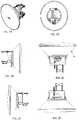
- FIGS. 1A-Fshow one variation of the conical shaped antenna assembly.
- FIG. 1Ashows an isometric view with the radome cover.
- FIG. 1Bshows a back view.
- FIG. 1Cshows a bottom view.
- FIG. 1Dshows a left view.
- FIG. 1Eshows a right view.
- FIG. 1Fshows a top view.
- the antenna assemblyincludes a substantially conical (and/or parabolic) primary reflector 11 having a base.
- a secondary reflector(not visible) is suspended proximate to an antenna positioned at the base.
- the vertex end of the conical shaped antenna assemblymay be electrically coupled to a final amplifier of a radio transmitter (not shown) such that the apex may function as an antenna feed point or feed area.
- the antennamay be impedance matched to the amplifier either by constructing the antenna assembly to predetermined dimensions or through an additional circuit (not shown) tuned to the impedance of the transmission system.
- the antennaWhen the radiator transmitter is transmitting, the antenna may be electrically excited at the frequency of transmission and radiate energy away from the antenna.
- FIGs. 2A-Fshows the front section of the assembly shown in FIG. 1 without the radome.
- FIG. 2Ashows an isometric view.
- FIG. 2Bshows a cross-sectional view.
- FIG. 2Cshows a top view.
- FIG. 2Dshows a back view.
- FIG. 2Eshows a left view.
- FIG. 2Fshows a right view.
- the primary reflector 11has a parabolic interior surface and a base.
- a rubber cowlencompasses the outer edge of the primary reflector. A portion of the cowl extends beyond the radome.
- the radomefits in the upper edge of the primary reflector. The cowl when mated to the radome protects the assembly from environmental conditions such as birds, rain, and sunlight thereby creating a waterproof and weatherproof seal.
- the primary reflectoris preferably made of aluminum.
- a support structureconnects a secondary reflector 13 to the primary reflector in an on-axis configuration.
- An antenna submount assemblyinterposes the primary and secondary reflectors such that the secondary reflector presents a reflective hyperbolic surface or convex surface to the antenna submount assembly.
- a shroudcovers the antenna submount assembly.
- the supporting structureconnects the secondary reflector to the primary reflector.
- the supporting structure 15includes three vertical shackles, e.g. three plastic arms. The arms are evenly distributed along the perimeter of the secondary reflector.
- This variationmay operate as a Cassegrain antenna, where a feed antenna is mounted at or behind the surface of the concave main parabolic reflector dish and is aimed at a smaller convex secondary reflector suspended in front of the primary reflector.
- the beam of radio waves from the feedilluminates the secondary reflector, which reflects it back to the main reflector dish, which reflects it forward again to form the desired beam.
- FIG. 3A and FIG. 3Bin concert, show an exploded view of the assembly shown in FIG. 1 .
- FIG. 3Bshows an expanded view of the antenna submount assembly 31.
- the antenna submount assemblyattaches behind the secondary reflector.
- a horn flange 35is centrally positioned on a base.
- a feed antennais secured to a plate.
- An O-ringinterposes the base and the plate.
- the feed antennacollects the signal from the secondary reflector and directs it to an orthomode transducer (OMT) probe.
- OMTorthomode transducer
- the primary feedis configured to couple to just two antenna feed inputs that each couple to a connector of a pair of connectors 33 (e.g., one for vertical polarization and one for horizontal polarization), as described in greater detail, three or more polarizations may be emitted from a primary feed, and particularly a primary feed 15 having an appropriate pattern of cut-out regions on metal emitter/radiator surface.
- This example of an OMT probemay also be referred to as a polarization duplexer. They are typically used to either combine or to separate two orthogonally polarized microwave signal paths. One of the paths forms the uplink, which is transmitted over the same waveguide as the received signal path, or downlink path. OMT probes are used with feed horn antennas to isolate orthogonal polarizations of a signal and to transceive signals to different ports.
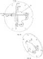
- FIG. 4A and FIG. 4Bshow close-up views of additional examples of the secondary reflector shown in FIG. 3 .
- the secondary reflectorhas a parabolic interior surface and a reflective hyperbolic exterior surface. This is an on-axis reflector configuration.
- the interior surface of the secondary reflectoris lined by a concentric support structure.
- the base of the secondary reflectorcovers the horn of the feed horn antenna. Alternatively, the interior surface of the secondary reflector may be continuous.
- FIG. 5shows a cross-sectional view of the feed horn antenna shown in FIGS. 1A-1F .
- the feed hornhas a narrow beamwidth/higher gain to focus its radiation on the smaller secondary reflector.
- the angular widthsubtends the feed horn typically 10-15 degrees.
- the phase center of the hornis placed at the focal point of the secondary reflector.
- the feed hornincludes a waveguide having an unvarying cross-sectional area and a horn that flares outward.
- the materialmay be made of metal.
- the primary feedis seated at the base of the waveguide.
- Each of the resonant arms (antenna inputs) of the primary feedattaches to the baseplate.
- the baseplateis attached via screws to the feed horn.
- the sudden end of the conductive wallsmay cause an abrupt impedance change at the aperture, from the wave impedance in the waveguide to the impedance of free space.
- this impedance-stepreflects a significant fraction of the wave energy back down the guide toward the source, so that not all of the power is radiated.
- the ends of the waveguidemay be flared out to form a horn.
- the taper of the hornchanges the impedance gradually along the horn's length. This acts like an impedance matching transformer, allowing most of the wave energy to radiate out the end of the horn into space, with minimal reflection.
- the taperfunctions similarly to a tapered transmission line, or an optical medium with a smoothly varying refractive index.
- the wide aperture of the hornprojects the waves in a narrow beam.
- the surface area of the horn that gives minimum reflected poweris an exponential taper.
- Conical and pyramidal hornsmay be used because they have straight sides and are easier to design and fabricate.
- FIG. 6shows a close-up top-down view of the radiator shown in FIG. 5 .
- FIG. 7A and 7Bshow a close-up expanded perspective of the antenna shown in FIG. 5 .
- the radiatoris a cross-shaped shorted primary feed 15.
- the primary feedis described with respect to a Cartesian coordinate system with axis labels x and y.
- the x and y axesare perpendicular with respect to one another.
- x-axial resonant armsthere are two x-axial resonant arms, each having a center line parallel to the x-axis.
- the x-axisis positioned between first and the second x-axial center lines.
- the y-axisis positioned between the first and the second y-axial center lines.
- the originis positioned at the intersection of the x-axis and the y-axis.
- the armsare opposing, such that a shorting wall to ground is positioned at the distal ends, e.g. away from the origin.
- the armsare offset such that the spacing between their corresponding center lines is ⁇ /2 where ⁇ is the wavelength of the antenna.
- ⁇ /2.
- the antennais further tuned by the shape of the patch in the x, y, and z axes.
- a slotis positioned within the patch.
- the slotradiates electromagnetic waves.
- the shape and size of the slot, as well as the driving frequency,determine the radiation distribution pattern.
- the radiatoris a patch made of a metal sheet mounted above a ground plane using dielectric spacers (not shown).
- the radiatormay be formed from an electrically conductive material of the type conventionally found in antenna radiators such as aluminum, copper and other malleable metals.
- the radiatormay be stamped from a single piece of electrically conductive material.
- a feed horndirects electric energy waves from a single substrate primary feed toward a secondary reflector.
- the feed hornincludes a waveguide connected to a horn.
- the primary feed(emitting surface) is positioned at the opening to the waveguide.
- the secondary reflectordirects the electric energy waves toward a primary reflector.
- the primary reflectorreceives reflected electric energy waves and directs the waves towards the secondary reflector.
- a collectorabsorbs only a portion of the reflected electric energy waves, the portion of the waves consists of only those waves which may otherwise reflect back to the primary feed.
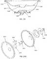
- FIGS. 8A-8GAnother variation of an antenna assembly is shown in FIGS. 8A-8G .
- the antenna assemblyincludes three inputs for three differently polarized RF signals, each of which may be emitted by the same primary feed toward a secondary reflector and a primary reflector for transmission from the assembly in the same direction with a uniform or near-uniform phase front.
- FIG. 8Aillustrates one variation of an antenna assembly
- FIG. 8Bshows an exploded view of this example
- the device 10includes a shaped radome 101 covering the outer opening of the primary reflector 103.
- the radomefits in the upper edge of a primary reflector 103.
- a secondary reflector(not visible in FIGS. 8A and 8B , but illustrated below in FIGS. 8C-1E ) is supported by the back side of the radome and is centrally positioned.
- FIG. 8Cis a back view of the radome of FIGS. 8A and 8B , showing the secondary reflector 104.
- FIG. 8Dis a side view of the radome including the secondary reflector attached at the center of the radome on the inner side
- FIG. 8Eis a sectional view through the radome.
- the secondary reflector 104which in this example is on the radome, may be positioned so that it reflects the different beams to the primary reflector and out of the antenna.
- the secondary reflector 104has a curved, convex outer surface, so that the RF signals are reflected within the primary reflector so that the primary reflector reflects the RF signals out of the apparatus, though the shaped radome which may help make the phase front of the RF signals more uniform.
- An antenna submount assembly 107attaches behind the secondary reflector at the base of the primary reflector 103.
- the antennamay collect the signal from the secondary reflector and direct it to an orthomode transducer (OMT) probe, which is also referred to as the primary feed having the emitter (or in the apparatuses described herein, a patterned emitter) 110.
- OMTorthomode transducer
- the OMT probeabsorbs the collected signal and conducts it to the connector (not shown).
- An OMT probemay also be referred to as a polarization multiplexer, and may be used to either combine or to separate orthogonally polarized microwave signal paths.
- OMT probesmay be used with (or without) feed horn antennas to isolate orthogonal polarizations of a signal and to transceive signals to different ports.
- the primary feed(including the patterned emitter) is a planar element 110, which is described in greater detail below, and may allow multiple beams having different polarizations to be directed from the same emitter (and thus, the same antenna apparatus). The beams may be independent and isolated from each other.
- the RF signals of different polarizationsare fed into the primary feed by different, and independent, antenna feeds, and the resulting RF signal beam leaves the emitter surface in different locations for the different polarizations, thereby reflecting from different regions of the primary and secondary reflectors in this example.
- rear housing 115covers the antenna submount assembly (emitter 110, PCB 112, and plate/horn 113). Within the rear housing 115, a probe housing holds the primary feed.
- a bracket assembly for mounting to a pole 121is attached to the back of the shroud and may include a locking/lockable adjustable elevation bracket 123.
- FIGS. 9A to 9Eillustrate different views of the assembly of FIGS. 8A-1B , from front ( FIG. 9A ), top ( FIG. 9B ), bottom ( FIG. 9C ), left side ( FIG. 9D ), and right side ( FIG. 9E ).
- FIGS. 10A-10Dillustrate the antenna submount assembly of the apparatus shown in FIGS. 8A-8E .
- FIG. 10Aillustrates the antenna submount assembly with a cover or cap 305.
- FIG. 10Billustrates the antenna submount assembly without the antenna cover, showing the emitter 310 and back plate 313.
- the back plate 113, 313may be configured as (or may include) a horn (and in such variations may be referred to as a horn), as shown below in FIG. 12C .
- FIG. 10Cis another view of the antenna submount assembly similar to that shown in FIG. 10B , but with the plate/horn portion removed, showing the emitter mounted to the supporting printed circuit board (PCB 312).
- PCB 312printed circuit board
- the PCBmay include the antenna circuitry, including radio circuitry and is shown connecting (via cable 355 connector) to one or more other devices, for processing the signals received and/or transmitted by the antenna apparatus.
- the circuitryis located on the back side of the support (PCB 312) and may include connections through the PCB to the isolated and independent feeds 342.
- FIG. 10Dshows a back view of the subassembly of FIG. 10C , illustrating the back of the PCB 312, including circuitry and the connection to the emitter.
- a central opening 365 through the emitteris visible in FIG. 10D , showing through which another element, such as a fiber optic or other lightpipe may be passed.
- the back of the apparatusmay include a plurality of connectors for connecting the antenna feeds to radio circuitry.
- the PCBacts as a substrate holding the emitter and radio circuitry; in some variations a separate substrate (or additional substrate(s)) may be used, including a ground plate.
- each antenna pathhas a corresponding sector for the primary and the secondary reflectors, and each sector may be optimized to improve the gain. These sectors (region s on the primary and secondary reflector) may be separate or overlapping.
- the multi-focal point antenna assembly shown in FIGS. 8A-8Eis a tripole antenna that may operate similar to a "planar inverted F type" antenna, in which the emitting surface includes both a shorting pin or shorting post on one side and a feed (feed point) along another side.
- a single feedis connected to a patch emitting surface and the overall dimensions of the surface are typically rectangular (or square) having a path length that adds up to a fraction (e.g., a quarter or half) of the desired wavelength.
- the emitters descried hereintypically have 3 or more feed points (feeds) corresponding to the beams to be emitted, and have three or more shorting posts, pins or surfaces.
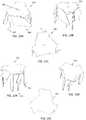
- FIGS. 11A-11Cillustrate an example of a primary feed having an emitter for a multi-focal point antenna, as described herein.
- the primary feed having a single (patterned) emitter shown in FIGS. 11A-11Cis the same as the primary feed shown in the example of FIGS. 8A-8E .
- the primary feedincludes an upper flat surface 466 (radiating/emission surface).
- FIG. 11Ashows a side perspective view of this primary feed.
- the emission (flat, upper) surfaceincludes an opening 465 that may be used to pass another element (such as a lightpipe, e.g., fiber optic, etc.).
- the overall shape of the primary feed in FIGS. 11A-11Cis roughly triangular, as is apparent in the top view shown in FIG.
- the outer circumferenceincludes folded-down regions and non-folded down regions (e.g., flaps 467) and/or cut-out regions (not shown in this example) which may slightly alter the overall triangular shape.
- the emitter shown in FIG. 11A-11Cis triangularly symmetric, so that each 120 degree radial slice of the device, taken from the top center of the emitter (as in FIG. 11B ), is repeated.
- the multi-focal emitters (primary feeds) described herein for emitting n beamsinclude n feeds.
- three antenna feeds (442, 442', 442")are shown, and the primary feed is configured to emit three beams, with each beam in a slightly different direction.
- three separate shorting (grounding) regions (pins, posts, etc.) 452, 452', 452"are shown.
- Each of the antenna feedsis typically isolated (electrically isolated) and independent of each other, and feeds onto the same plate/plane.
- the antenna feedseach connect to a folded-over flap region that is adjacent to the shorting element (pin or post).
- electrical energy fed by each antenna feedmay result in emission of an RF signal having a slightly different average vector (e.g., beam angle/polarization).
- the beamsmay be, in some cases, orthogonal to each other.
- FIGS. 12A and 12Billustrate an alternative variation of an antenna subassembly including a primary feed and an emitter and backing (PCB) also including radio circuitry for a multi-focal-point antenna.
- the sub-assembly shown in FIG. 12Aincludes a horn 513 around the emitter element 510.
- the subassemblymay also include feed lines from the radio circuitry connected to and feeding the feeds attached to the resonating emitter plate, and a DC-shorting plate (e.g., a ground plane/plate) that is connecting the ground and the top plate through the aforementioned shorting pins/posts.
- FIG. 12Bshows the subassembly of FIG. 12A with the horn removed.
- the primary feed having an emitter shown in FIGS. 12A-12Bhas a slightly different geometry than the emitter of FIGS. 11A-11C .
- the primary feed element(with an emitter or emitter surface, also referred to as a radiator) is a made of a metal sheet having a central planar region, with one or more folded-down regions from which the feed and shorting posts/pins connect, as illustrated.
- This emitters described hereinmay be referred to as patterned antenna radiating emitter (or simply patterned emitters), because they may include repeated patterns of flaps (e.g., islands) and cut-out regions; these patterned regions may be radially repeated to form the overall pattern of the emitter.
- the cut-out regionsmay be notches in the edge of the emitting surface, or inside the periphery of the emitting surface. In some variations the cut-out regions are on the folded-over regions continuous with the flat upper surface.
- the patterned emitter of the primary feedmay be mounted above a ground plane using dielectric spacers (not shown). In general, the patterned emitter may be formed from an electrically conductive material of the type conventionally found in antenna radiators, such as aluminum, copper and other malleable metals.
- the primary feed(including the emitter/radiator surface) may be stamped from a single piece of electrically conductive material.
- FIG. 12Cis a side perspective view of the antenna subassembly of FIGS. 12A and 12B , showing the primary feed with a patterned antenna radiating emitter 510 projecting slightly above the horn 513 from the base plate of the PCB.
- the multi-beam primary feeds including patterned antenna radiating emittersmay be generally shaped as an equilateral triangle (e.g., having a "trianguloid" shape). In some variations an apex of each triangle is grounded and there are three antenna feed points (antenna input feed points), each proximate to one of the apices.
- One or more opening, hole, slot, etc.e.g., in FIGS. 11A-11C the opening is triangularly shaped
- the primary feedmay be shaped such that energy entering from each antenna input feed does not interfere with energy from other antenna input feeds.
- the topology of the antenna as well as slot shape and positionmay be chosen according to the desired performance characteristics.
- the primary feed 610includes a flat planar emitting surface, and three antenna input feeds 642, each connected to flap bent down from the upper emitting surface, and three shorting (ground) pins/posts 652.
- the primary feedalso includes a small opening/slot 665in the center of the upper emitting surface.
- FIGS. 13B and 13Cshow another side perspective view and a top view, respectively, of the same primary feed with an antenna radiating element.
- the antenna input feedsmay be insulated or covered along at least part of their length by a surrounding sheath.
- the exemplary primary feed having an antenna radiating element 710 in FIGS. 14A-14Cis generally triangular in shape (trainguloid), but does not include a central opening/slot.
- the planar emitting surfaceis fed by three antenna input feeds 742 connected to a bent-over flap region that is positioned adjacent to a shorting pin/post 752 which connects to the upper planar emitting surface by a separate flap region.
- a multi-beam antenna system having a single primary feed with a single emitteris configured so that it includes a primary reflector 103 and a secondary reflector, as discussed above.
- the primary reflector and secondary reflectorshave different regions that are targeted by each of the different beams to/from the patterned antenna radiating emitter surface. For example, for each radiating element, there may be a corresponding "wedge" (e.g., radial region) of the primary reflector and a corresponding wedge (e.g., region) of the secondary reflector that direct energy from each beam.
- each wedgespans 120 approximately degrees.
- alignment markingsmay be included on the reflectors to ensure that each antenna path is centrally positioned within the respective wedge.
- This configurationmay effectively allow multiple "beams" (as from multiple, offset antennas) to be handled by a single antenna.
- a primary feed with an emitter(such as the ones shown in FIGS. 11A , 13A or 14A ) having multiple antenna input feed points, e.g. 3, may be positioned within a feed horn, as shown.
- the emitter of the primary feed in these examplesis a triangular-shaped shorted emitter with three antenna paths, however other variations may include more than three independent antenna input feeds and corresponding paths (e.g., four, five, six, seven, eight, or more feeds and a corresponding number of paths/beams).
- the emitterWhen a driving frequency is applied to the primary feed's emitter surface, the emitter typically radiates electromagnetic waves.
- the horn(when present) is on-axis with the origins of the primary and the secondary reflectors.
- the hornmay have a slightly larger diameter than that of the secondary reflector.
- the hornmay have a subtended angle such that for each sector (corresponding to each of the beams), the antenna signal is received and directed from the secondary reflector to the primary reflector.
- the flare of the hornmay be optimized for each sector.
- this apparatusis not limited to tripole sector antennas, but may include antenna assemblies that have a primary feed fed by more than three antenna input feeds (e.g. n feeds) capable of detecting/emitting n signals paths, where n ⁇ 2 (and particularly n ⁇ 3).
- the apparatusmay also include a primary reflector, a secondary reflector, and a collector (including a primary feed).
- the antennamay be referred to as a feed horn antenna.
- the antennamay have a waveguide that interposes a horn and a radiator configured to emit n independent beams in different (average) directions, each transmitting a signal.
- a primary reflectorwhen used may have n regions, each region directing electric energy waves corresponding uniquely to one of the n signals, each region a portion of a parabolic surface.
- a secondary reflectormay have n regions, each region directing electric energy waves corresponding uniquely to one of the n signals toward its corresponding region of the primary reflector, and each region may have a hyperbolic (e.g., convex) surface.
- the collectormay absorb only a portion of the electric energy waves directed toward the secondary reflector, the portion of the waves consists of only those waves which may otherwise reflect back to the feed horn antenna.
- any of the antenna systems described hereinmay also be configured to have a single reflector.
- a secondary reflectoris not included, but the primary feed of the antenna is suspended above the base of a primary reflector.
- the energymay exit the antenna and reflects off the primary reflector portion in a corresponding sector.
- the feed horn antenna(including the primary feed) can also emit n signals, where n ⁇ 2.
- the variations shownare not drawn to scale.
- the (average or net) output of each antenna signalmay be positioned along a unique ray.
- the raysare equally distributed and the corresponding radii are the same length.
- the raysare symmetric along the 0 and 180 rays or along the 90 and 270 degree rays.
- the raysare not evenly distributed and the corresponding radii have dissimilar lengths
- an adjustable bracketis included.
- an L-shaped bracketis shown in FIG. 8A and 8B , and is positioned adjacent the rear housing.
- One end of the L-shaped bracketincludes a housing hole that receives the threaded portion of the rear housing.
- On opposing edges of the housing holethere are two extended lips. The lips, when a quarter turn twist is applied, secure the bracket to the base of the partially threaded support.
- the opposite end of the brackethas an alignment slot and an anchor hole. There are alignment markings positioned near the alignment slot indicating angles.
- the detents and the radially positioned postsorient and secure the bracket with respect to the rear housing.
- This examplealso includes a pole bracket having two holes that are separated by a distance of at least the diameter of a pole.
- the pole bracketfurther includes an alignment post.
- a U-bolt having two threaded endsis shown positioned to fit into the holes of the bracket.
- the L-shaped bracketmay be attached to a pole (not shown) when the U-bolt is positioned through the pole bracket and then the bracket.
- the alignment post of the pole bracketmoves within the alignment slot of the L-shaped bracket.
- the combination of the U-bolt and the pole bracketis used to adjust the tension.
- the antenna assemblyis attached when the rear housing is positioned into the housing hole and a quarter turn is applied. The operator can pivot the antenna assembly about the thread closest to the alignment slot.
- a method of operating the antenna assemblymay generally include transmitting at least n directional antenna signals, where n ⁇ 2, from a single emitting element of the antenna; the method may include transmitting each of the n beams towards a reflector that has a unique corresponding region for each antenna signal.
- the reflectormay receive reflected electric energy waves by the reflector.
- a collectormay absorb only a portion of the reflected electric energy waves, the portion of the waves consists of only those waves which may otherwise reflect back to the single substrate antenna array.
- a method of operating the antenna assemblymay also or alternatively include transmitting at least n directional antenna signals, where n ⁇ 2, from a single emitter towards a secondary reflector that has a unique corresponding region for each antenna signal (beam).
- the n directional antenna signalsmay be directed by a feed horn.
- the electric energy wavesmay from a secondary reflector that is directed towards primary reflector that has a unique corresponding region for each antenna signal (beam).
- the primary reflectormay receive reflected electric energy waves.
- the secondary reflectormay receive reflected electric energy waves by the primary reflector and direct it to a collector.
- a collectormay absorb only a portion of the reflected electric energy waves, e.g., the portion of the waves consisting of only those waves which may otherwise reflect back to the single substrate antenna array.
- the n directional antenna signalsmay be aligned with the corresponding regions on the reflectors.
- FIGS. 15A and 15Billustrate another variation of a wireless transmission stations having a multi-focal point antenna with a single emitter adapted to emit three or more independent beams.
- the apparatusis configured as an access point from which multiple beams may be transmitted/received, allowing for a single antenna that can operate as a MIMO device.
- the entire devicemay has a relatively small footprint (as shown in FIG. 15A ), with an outer dome-like cover and a central region that may light up to indicate the status of the device (e.g., on/off, transmitting/receiving, error, etc.).
- the devicemay be mounted on an interior or exterior surface (e.g., ceiling, wall, etc.). An exploded view of this apparatus is shown in FIG. 15B .
- the outer cover (top cover) 802is removed and the component parts (or assemblies of parts) are shown in a partially exploded view.
- the indicator lighte.g., LED
- the indicator lightincludes a lightpipe 804 having a cover (LED cover 806).
- a washer or illumination ringmay also be included.
- the lightpipewill be described in more detail below.
- a bottom cover 808may also be included, and may enclose the emitter 810 and radio circuitry 812.
- the antennadoes not include a reflector. Instead, the emitter directly received and/or transmits.
- FIG. 16is a top view of the interior of the wireless access point of FIG. 15A with the enclosure and lightpipe cover removed, showing a top view of the interior of the device, looking down on the lightpipe which is on top of the emitter.
- the emitter in this examplealso includes a hole through which the lightpipe passes.
- the circuitryis schematically illustrated in this example. The emitter is connected above the PCB including the circuitry.
- FIGS. 17A and 17Bare cross-sectional views through the xz and xy axes, respectively, showing the relationship between the emitter, lightpipe and radio circuitry.
- the emitteris connected via three feeds (though, as discussed above, more than three feeds may be used in some variation having an emitter configured to emit more than three beams) connected to an overhanging region of the planar emitting surface. In these figures three ground (shorting) connections are also made to the planar surface of the emitter.
- FIG. 18is another top view of the interior of the wireless access point similar to that shown in FIG. 16 , but with the lightpipe removed, showing the planar emitting (top) surface of the emitter.
- FIGS. 21A-21BA more detailed view of the primary feed having a single emitter is shown in FIGS. 21A-21B.
- FIG. 21Ais a front perspective view of a primary feed having an emitter (with another variation of a patterned antenna radiating emitter).
- the overall shape of the emitteris also approximately triangular (trianguloid), with notched/cut-out region along the edges of the planar top emitting surface; in addition one or more flaps or islands are folded down away from (and perpendicular to) the flat emitting top surface.
- the three antenna input feeds 1442 and shorting posts/pins 1452are each connected to a folded-over flap region; the feeds may be insulated.
- the antenna input feedsare typically connect to a feed line and thus to the radio circuitry; the shorting posts/pins may be connected to a ground.
- the antenna input feedmay connect to a connector (e.g., RF signal input connector) to connect to a radio circuitry (e.g., a radio device).
- Each connectormay correspond to one of the antenna input feeds.
- the antenna input feed linesmay be isolated from each other and independent of each other, and arranged along with the shorting pins/posts so that three (in this example) independent beams are emitted in three distinct directions.
- FIGS. 22A and 22BAnother variation of an emitter is shown in FIGS. 22A and 22B ; the primary feed with a single emitter in this example does not include an opening (slot) through the planar emitting surface as in the variation shown in FIGS. 21A-21B and 15A-15B . Instead, the planar emitting surface extends completely across the surface. Both feeds 1542 and shorting posts/pins 1552 are also included and arranged similarly to the arrangement shown in FIGS. 21A-21B .
- the wireless access point systemconsists of a bottom enclosure, e.g. shallow dish shaped housing, having a printed circuit board (PCB) contained within.
- the PCBcontains radio circuitry to provide wireless access functionality.
- a primary feed with a radiator element having an opening (slot, aperture, etc.)may be directly connected to the PCB by grounding (shorting) pins or legs and at least one feed point, such that the element is suspended above the printed circuit board (PCB).
- a light emitting diodeis electrically connected to the PCB, as shown in FIGS. 17A and 17B .
- a covermates to the top enclosure.
- a stem portion of a lightpipe 1216encompasses the emission portion of an LED and extends through the aperture and the hole of the cover.
- An O-ringinterposes the bottom rim of the lightpipe and the top enclosure.
- the coveris comparable in size to the cross-sectional area of the lightpipe and covers the lightpipe.
- a cable for Ethernet accesselectrically connected to the circuitry, may extend through the mated enclosures.
- a lightpipeis funnel-shaped, having a conical mouth and a stem.
- the mouthhas a larger perimeter than the stem.
- the stemencompasses the LED.
- the rim of the mouthextends beyond the cover of the access point.
- the mouthmay be shaped as a cone.
- the lightpiperedirects the LED light output to the desired location with minimal loss of intensity.
- the lightpipeis made of a polycarbonate material.
- the example shown in FIGS. 15A-19Bis a vertical lightpipe, however, angled or planar lightpipes may also be used, or other light guides (including fiber optics) may be used.
- FIGS. 19A and 19Bhas a circular mouth.
- FIG. 19Ais a cross-sectional perspective view and FIG. 19B is a top view of the lightpipe.
- the mouthhas a shallow profile and is dome shaped.
- FIGS. 20A and 20BAnother variation is shown in FIGS. 20A and 20B .
- the lightpipehas a square mouth.
- FIG. 20Ais a cross-sectional perspective view.
- FIG. 20Bis a top view of the lightpipe.
- the mouthhas a shallow profile and is shaped as a truncated square pyramid.
- the aperture of the radiator elementmay be a polygon, e.g.
- the aperture through the emittermay be an opening having a portion large enough to accept the stem of the lightpipe.
- the shape, diameter, or depth of the mouth, length of diameter of the stemmay all vary, and the surface of the conical mouth of the lightpipe may be textured, etc. to effect light extraction from the LED. Further the top of the enclosure may be textured to effect light extraction.
- the front of the antenna assemblyis shown.
- the front of the antenna assemblyincludes a primary radome 2313 coving the opening into the primary reflector 2303 which includes a parabolic inner surface (not visible in FIGS. 23A or 23B ).
- the apparatusincludes four connectors 2309 (antenna input connectors) that are coupled to the four antenna input feeds connecting to the primary feed, as will be described below in reference to FIGS.
- antenna input feedsmay be connected to a radio device having two or more antenna output lines.
- a radio device having a vertical and horizontal polarization outputs/inputsmay be connected to the antenna device so that each of the four antenna inputs 2309 (antenna polarization RF signal inputs) is connected to either the vertical polarization, a shifted (e.g., inverted, phase shifted, etc.) version of the vertical polarization output/input.
- pair of outputsmay be the same, but may be inverted (e.g., +vertical polarization/-vertical polarization, etc.).
- FIGS. 23D and 23Eillustrate the inside of the opening formed within the primary reflector having a parabolic inner surface, after removing the outer (primary) radome covering the opening and an inner (secondary) radome that is shaped.
- the sub-assembly including the primary feed 2321in FIG. 23E ) is covered by a cap or sub-radome 2318; in FIG. 23E this protective cap/sub-radome 2318 has been removed, showing the upper (radiator) surface of the primary feed 2321.
- FIGS. 24A and 24Billustrate the antenna sub-assembly including the primary feed 2321.
- the sub-assemblyincludes the ground plate 2405 and a horn portion 2402 around the primary feed 2321.
- FIG. 24Bthe sub-assembly is shown without the horn, showing that the primary feed is connected via multiple projections 2409 to the ground, and there are four (in FIG. 24B , only two are visible) antenna input feeds 2407 that feed onto the emitter surface of the primary feed.
- the primary feed in this exampleis approximately square, having a plurality of cut-out regions that may help form the four separate beams corresponding to the separate antenna input feeds (and therefore separate polarized RF signals).
- FIG. 23Fa cross-section through the antenna assembly of FIG. 23A is shown.
- the arrangement of the primary reflector 2303, secondary reflector 2304 and primary feed 2321is shown.
- a primary radome 2313covers the opening into the primary reflector 2303, and within the primary reflector is a secondary radome 2314 that is shaped to lens RF signals transmitted through the secondary radome so the phase front of the transmitted RF signals is uniform (or approximately uniform).
- FIG. 23Gis an exploded view of the apparatus of FIG.
- RF signals(e.g., having different polarizations) applied to each of the antenna input feeds 2407 may be transmitted as separate beams from the primary feed (e.g., the patterned antenna emitting surface), to be reflected off of the secondary reflector that is arranged immediately opposite from the patterned antenna emitting surface of the primary feed, and then reflected off of the primary reflector for transmission out of the apparatus. This is illustrated in FIG. 25 .
- a first RF signalmay be applied (e.g., by a radio circuitry) to a first antenna input feed (via a first antenna input connector 2501).
- This first RF signalmay be transmitted via the first antenna input feed to the emitter surface of the primary feed, where it is emitted as a first beam 2504 from a first region of the emitting/radiating surface, as shown by the arrow extending from the right side of the primary feed.
- This first beamis reflected by the convex secondary reflector opposite the primary feed, to the parabolic wall of the primary reflector, as shown by the arrows, and then emitted in a directional beam from the apparatus.
- a similar processmay occur with each beams formed by RF signals from each of the other antenna input feeds, such as the beam 2506 emitted in response to an applied RF signal from a second antenna input connector 2503.
- the resulting beam for the RF signal emitted by the emitter/radiator surface of the primary feedis centered at a different portion of the emitter surface.
- the beamis reflected from a different region (sector) of the secondary reflector and primary reflector.
- both beams(and indeed all of the beams emitted by the primary feed exit the apparatus in approximately the same direction.
- the RF signals emittedmay also have an approximately uniform phase front when leaving the apparatus.
- references to a structure or feature that is disposed "adjacent" another featuremay have portions that overlap or underlie the adjacent feature.
- the devicemay be otherwise oriented (rotated 90 degrees or at other orientations) and the spatially relative descriptors used herein interpreted accordingly.
- the terms “upwardly”, “downwardly”, “vertical”, “horizontal” and the likeare used herein for the purpose of explanation only unless specifically indicated otherwise.
- first and secondmay be used herein to describe various features/elements (including steps), these features/elements should not be limited by these terms, unless the context indicates otherwise. These terms may be used to distinguish one feature/element from another feature/element. Thus, a first feature/element discussed below could be termed a second feature/element, and similarly, a second feature/element discussed below could be termed a first feature/element without departing from the teachings of the present invention.
- a numeric valuemay have a value that is +/- 0.1% of the stated value (or range of values), +/- 1% of the stated value (or range of values), +/- 2% of the stated value (or range of values), +/- 5% of the stated value (or range of values), +/- 10% of the stated value (or range of values), etc. Any numerical range recited herein is intended to include all sub-ranges subsumed therein.
Landscapes
- Physics & Mathematics (AREA)
- Electromagnetism (AREA)
- Engineering & Computer Science (AREA)
- Computer Networks & Wireless Communication (AREA)
- Signal Processing (AREA)
- Aerials With Secondary Devices (AREA)
- Variable-Direction Aerials And Aerial Arrays (AREA)
Description
- Described herein are wireless radio and antenna apparatuses and methods that may form part of a broadband wireless system. The apparatus may be used for accessing the internet, even in relatively remote regions, and in particular may operate as multiple-input, multiple-output (MIMO) antennas having a single emitter which is capable of directing multiple (e.g., three or more) beams therefrom. The wireless transmission stations described herein may be configured for indoor, outdoor, or indoor and outdoor use.
- There is an increasing demand for radio frequency (RF) communication systems to provide high-speed data transmissions in a reliable manner. In order to enable high-speed data transmission over a wireless channel, which uses limited bandwidth and power, it may be important to increase capacity. The reliability of reception signals may be greatly degraded by fading, shadowing, wave attenuation, interference, etc. An antenna that is capable of multiple input/multiple output (MIMO) operation, without requiring a number of separate antennas and/or separate antenna emitters, that could be reliably and inexpensively manufactured and provide reliable operation may address these problems and provide numerous other advantages.
- Typically, MIMO antenna technology uses a spatial multiplexing technique for transmitting data at high speeds without further increasing the system's bandwidth, by using multiple antennas at the transmitter or receiver to transmit different data simultaneously. However, the use of multiple antennas may be expensive in both actual cost and in the footprint and size of the arrangement. Thus, it would be particularly beneficial to provide an antenna that may operate in a MIMO configuration, and particularly in ani xp arrangement (where i is a positive integer greater than 3, andp is some integer greater than 2), allowing operation with multiple streams of RF data from a single compact antenna, and particularly an antenna having a single emitter.
- To date, most MIMO antennas have an arrayed antenna structure that uses multiple radiators (emitters), and since a multiple number of radiators are used, there can be interference occurring between the radiators. Such interference can distort the radiating pattern or create a mutual coupling effect among the radiators. In order to minimize interference between radiators, a MIMO antenna may use an isolation element, i.e. a separate feature, or may use a structure in which the radiators are widely separated from one another. In these cases, providing the desired isolation basically involves providing a sufficient distance between two antennas, even in cases where a separate isolation element is used. However, since the demand for smaller terminals is an ongoing requirement, and since providing a sufficient distance between multiple antennas not only is very difficult but also runs contrary to providing smaller terminal sizes, there is a need for an isolation technique that can be applied for multiple antennas that are positioned relatively closely to one another.
- Households and businesses in areas without wired connections (e.g., in regions that cannot be reached via conventional communication media, such as optical cables, copper cables, and/or other fixed wire-based technologies) may rely on fixed wireless services for some of these services (e.g., broadband access). Fixed wireless services can be made more attractive to customers by effectively leverage existing customer premises equipment (CPE).
- There is a growing need to develop systems to deliver broadband to remote and under-served regions, for which traditional broadband (e.g., wired or cabled delivery) is not available or possible. Delivering high performance networking in underserved and underpenetrated regions is challenging because of the lack of durable and powerful systems, including antenna-based systems, capable of operating with sufficient flexibility to provide point-to-point as well as point-to-multipoint communication between client stations (e.g., home or business locations) and an internet service provider, including wireless internet service providers.
- To keep the costs of these devices down, so that they may be provided to even underserved communities at a reasonable price, the antennas are produced to be reliable, easy to manufacture, and easy to use. In addition, these antennas have a sufficiently large bandwidth in an appropriate band. Further, the devices are compact, yet have minimal line radiation and other sources of noise.
- The systems may include user-friendly devices including amplifying, broadband radios/antenna that are robust (including for use in outdoor regions), and easy to install and use. Described herein are antennas that may be used for MIMO operation that may resolve the problems described above and provide an antenna having a single emitter adapted to emit three or more independent beams using a patterned antenna radiating emitter. These antennas may therefore also be referred to as multi-focal-point antennas. As described in greater detail below, the antennas described herein can provide isolation of the three or more beams even using a single (relatively small) emitter.
- The devices described herein may also be of particular use to deliver broadband data services to remote and under-served regions, for which traditional broadband (e.g., wired or cabled delivery) is not available or possible. Delivering high performance networking in underserved and underpenetrated regions is challenging because of the lack of durable and powerful systems, including antenna-based systems, capable of operating with sufficient flexibility to provide point-to-point as well as point-to-multipoint communication between client stations (e.g., home or business locations) and an internet service provider, including wireless internet service providers. In addition, the systems described herein may also be of particular use when delivering information in congested urban areas, which may otherwise provide numerous barriers to transmission. Thus, described herein are apparatuses (e.g., devices and systems) and methods of operating them that may address the issue raised above.
US2011/181479A discloses a feed assembly for a reflector antenna including an aperture common to low, mid and high frequency bands.US2011/0068988A discloses a multi-beam, multiband antenna with a main reflector, multiple feed horns and a sub-reflector.CN202042599U discloses a dual reflector antenna with an antenna dome.- According to the present invention, there are provided an antenna assembly and a method of transmitting radio frequency (RF) signals from an antenna assembly as defined in the appended claims.
- Described herein are antenna assemblies that may be configured as wireless transmission stations, such as wireless broadband access devices. These antenna assemblies may include a primary feed with a single emitting/receiving plate (e.g., patterned antenna radiating emitter) that this adapted to transmit and receive electromagnetic energy in three or more independent beams. The emitting/receiving plate may be referred to herein as an emitter, or a patterned antenna radiating emitter, or the like. The patterned antenna radiating emitter is configured so that a plurality of three or more independent (and isolated from each other) input feeds connect to the patterned antenna radiating emitter.
- Any of the antenna assemblies described herein may also be configured to include dual antenna reflectors for transmission of the multiple beams in the same direction (e.g., from the same pair of dual reflectors). The emitted RF signals, which may be referred to as beams, are emitted from the primary feed, and may include a plurality (2 or more, e.g., 3, 4, 5, etc.) of beams that are differently polarized. For example, the beams may be rotated versions of each other, including orthogonal beams. The same primary feed, including a single emitting surface may be used to emit all of the differently polarized beams. Each differently polarized beam is emitted from a different portion of the patterned antenna emitting surface of the primary feed, so that the differently polarized beams are directed to the secondary reflector, which is positioned opposite from the patterned antenna emitting surface of the primary feed and reflects the emitted beams towards the primary reflector that is oriented to direct the beams outward, away from the patterned antenna emitting surface of the primary feed. Each differently polarized beam may be reflected from a different sub-region of the secondary reflector and then from a sub-region of the primary reflector. The secondary reflector is a generally convex reflector that directs the electromagnetic energy (beam) towards the primary reflector. The primary reflector is a generally concave reflector that directs the electromagnetic energy. The secondary reflector is within a concavity formed in the parabolic primary reflector. In variations including dual reflectors, the differently polarized beams may be emitted in the same direction from the primary reflector, and the phase front of all of the beams may be uniform. Any of these apparatuses may include a shaped radome over the primary (and secondary) reflector to help tune (e.g., by lensing through the radome) the phase front of the RF energy transmitted through the radome. In some variations a pair of radomes may be used, including one that is curved to act as a lens to make the phase front of emitted RF signals more uniform. RF signals (beams) may be received by the apparatus in a similar way, e.g., reflected by the primary reflector to the second reflector and onto the patterned antenna emitting surface of the primary feed.
- The antenna assemblies and methods described herein, including devices and systems, may be wireless broadband access devices that are configurable as a point-to-point or point-to-multipoint stations.
- Any of the antenna assemblies described herein may include radio circuitry for generating and/or receiving RF signals of different polarizations (e.g.,n different polarizations, wheren is greater than 2, greater than 3, etc.). The radio (e.g., control) circuitry may be configured to control transmission and receipt of broadband information to and from the antenna.
- For example, described herein are multi-focal-point antenna device having a single emitter adapted to emit three or more independent beams. Such devices may include: a patterned antenna radiating emitter, wherein the patterned antenna radiating emitter comprises a sheet of metal having a plurality of cut-out regions along one or more edges of the patterned antenna radiating emitter;n antenna input feeds, wheren is 3 or more, separately extending to the patterned antenna radiating emitter, wherein each of then antenna input feeds are independent and electrically isolated from each other; and a radio circuitry coupled to each of the n antenna input feeds, wherein the radio circuitry is configured to transmit radio frequency (RF) signals so that each of then antenna input feeds transmits at a different polarization, wherein the patterned antenna radiating emitter emits n beams in which each of the n beams is differently polarized, and wherein the beams do not couple with each other.
- In operation, each of then beams may act as a separate "antenna" for MIMO, as each beam will have a different path between the transmitter and receiver. Thus, a single antenna capable of producing multiple antenna beams from a single emitter element, as described herein, may be used in a MIMO configuration.
- Any of the devices described herein may include a primary reflector that separately reflects each of the beams. For example, the reflector may haven wedge-shaped surface regions, each of then surface regions reflecting one or the n emitted beams. The apparatus may also include a secondary reflector havingn wedge-shaped surface regions, each of then surface regions may reflect one of then emitted beams to one of then surface regions of the primary reflector.
- In some variations, n is 3. The resulting beams may be 120 degrees off from each other (e.g., equally spaced), or in some variations spaced differently relative to each other (e.g., two and 90 degrees apart from each other and 180 degrees apart from the third, etc.). In some variations, n is four, and the beams are, e.g., 90 degrees from each other. In general,n may be any integer greater than 3 (e.g., 3, 4, 5, 6, 7, 8, 9, 10, etc.).
- In general, the shape of the patterned antenna radiating emitter may be any appropriate shape. The shape is generally planar in a central region, with edge regions folded downward. The patterned antenna region may include cut-out regions at the edges and/or in the central (planar) region. In some variations the patterned antenna radiating emitter has a generally triangular, rectangular, hexagonal, circular, etc. shape. For example, the shape of the patterned antenna radiating emitter may be generally triangular shape. As mentioned, the central region (between the bent edges) may be flat or substantially flat.
- For example, a patterned antenna radiating emitter may comprise a flat central surface with one or more edges folded down away from a central plane of the patterned antenna radiating emitter. Then antenna input feeds may be directly coupled ton edge regions of the patterned antenna radiating emitter. The patterned antenna radiating emitter may be formed of a single sheet of metal.
- In some variations the patterned antenna radiating emitter includes a cut-out region (e.g., hole, opening, passage, etc.) through which a structure may pass, such as a lightpipe, LED, or the like. The cut-out region may be in the center of the patterned antenna radiating emitter. For example, a patterned antenna radiating emitter may include a central opening for passing a light port. Thus, in general, the apparatus may include a lightpipe passing through the patterned antenna radiating emitter.
- In some variations the apparatus, and the patterned antenna radiating emitter in particular, is adapted (e.g., the patterned antenna radiating emitter is sized) to operate in both a 5 GHz and a 2 GHz regime. For example, the patterned antenna radiating emitter may have an emitting surface having an average diameter of between about 5 cm and 12 cm. Because the emitting surface (e.g., the flat/planar central surface) may be irregularly shaped, including non-circular, triangular, or asymmetrically shaped, the diameter may refer to the maximum or average diameter.
- In general, the radio circuitry may be configured to transmit radio frequency (RF) signals so that each of then antenna input feeds transmits at a different polarization, spectral signal and/or delay.
- Thus, described herein are multi-focal-point antenna devices having a single emitter adapted to emit three or more independent beams that may be used as a multiple input, multiple output (MIMO) antenna. For example, such a device may include: a base plate; a unitary patterned antenna radiating emitter positioned above the base plate, wherein the patterned antenna radiating emitter comprises a single sheet of metal having a plurality of cut-out regions along one or more outer edges of the patterned antenna radiating emitter;n antenna input feeds, wheren is 3 or more, extending through the base plate to the patterned antenna radiating emitter, wherein each of the n antenna input feeds are independent and electrically isolated from each other; and a radio circuitry coupled to each of then antenna input feeds, wherein the radio circuitry is configured to transmit radio frequency (RF) signals so that each of then antenna input feeds transmits at a different polarization, spectral signal and/or delay, wherein the patterned antenna radiating emitter emitsn independent and uncoupled beams.
- The base plate may be configured as a ground plate in any of the variations described herein.
- In one example, the antenna devices described herein include a triple focal-point antenna device having a single emitter adapted to emit three independent beams, the device comprising: a patterned antenna radiating emitter, wherein the patterned antenna radiating emitter comprises a sheet of metal having a plurality of cut-out regions along one or more outer edges; three antenna input feeds each separately extending to the patterned antenna radiating emitter, wherein each of the three antenna input feeds are independent and electrically isolated from each other; and a radio circuitry coupled to each of the three antenna input feeds, wherein the radio circuitry is configured to transmit radio frequency (RF) signals so that each of the three antenna input feeds transmits at a different polarization, wherein the patterned antenna radiating emitter emits three independent and uncoupled beams. As mentioned above, the patterned antenna radiating emitter may generally have a triangular shape, and may be flat (at least in the central region; the edges may be folded downward). The antenna input feeds may be connected to a portion of the folded-down edge. As mentioned, the patterned antenna radiating emitter may include a central opening for passing a light port, and a lightpipe may pass through the patterned antenna radiating emitter.
- For example, the three antenna input feeds may be directly coupled to three edge regions of the patterned antenna radiating emitter. The patterned antenna radiating emitter may be formed of a single sheet of metal. The patterned antenna radiating emitter may be sized to operate in both a 5 GHz and a 2 GHz regime. For example, the patterned antenna radiating emitter may comprise an emitting surface having an average diameter of between about 5 cm and 12 cm.
- In some variations the radio circuitry is configured to transmit radio frequency (RF) signals so that each of the three antenna input feeds transmits at a different polarization, spectral signal and/or delay.
- In some variations the antenna device is configured as a triple focal-point antenna device having a single emitter adapted to emit three independent beams that may be used as a multiple input, multiple output (MIMO) antenna. For example, a device may include: a base plate; a generally triangular antenna radiating emitter positioned above the base plate, wherein the generally triangular antenna radiating emitter comprises a sheet of metal having a plurality of cut-out regions along one or more outer edges; a light port opening through a central region of the generally triangular antenna radiating emitter; three antenna input feeds extending through the base plate to the triangular antenna radiating emitter, wherein each of the three antenna input feeds are independent and electrically isolated from each other; and a radio circuitry coupled to each of the three antenna input feeds, wherein the radio circuitry is configured to transmit radio frequency (RF) signals so that each of the three antenna input feeds transmits at a different polarization, spectral signal and/or delay, wherein the triangular antenna radiating emitter emits three independent and uncoupled beams.
- Also described herein are wireless transmission stations, including wireless broadband access devices. Any of the antennas described herein may be configured as part of a broadband access device and/or wireless access point ("AP"). These apparatuses, including devices and systems, may be wireless broadband access devices that are configurable as a point-to-point or point-to-multipoint stations. In general, the apparatuses described herein may include an antenna and control circuitry configured to control transmission and receipt of broadband information to and from the antenna. The antennas described herein may also be configured and/or referred to as planar antennas. As mentioned, in some variations, an antenna assembly includes a feed horn antenna emittingn signals, wheren ≥ 2, a primary reflector, a secondary reflector, and a collector. Some of the antennas described herein are configure as feed horn antennas. A feed horn antenna may have a waveguide that interposes a horn and a radiator configured to emitn beams, where each beam can comprise a signal. The primary reflector hasn regions, each region directing electric energy waves corresponding uniquely to one of then signals, each region having a parabolic surface. The secondary reflector may haven regions, each region directing electric energy waves corresponding uniquely to one of then signals toward its corresponding region of the primary reflector, each region having a hyperbolic surface. The collector may absorbs only a portion of the electric energy waves directed toward the secondary reflector, the portion of the waves consists of only those waves which may otherwise reflect back to the feed horn antenna.
- As mentioned, any of the antenna assemblies described herein may be configured to direct the emitted beams (rather than acting as omnidirectional or semi-omnidirectional). Thus, any of these examples may include at least one reflector, though in particular variations including two (or more) reflectors are described.
- For example, an antenna assembly may include: a primary reflector having a concave reflecting surface configured to direct electromagnetic energy; a secondary reflector within the primary reflector having a convex reflecting surface configured to direct electromagnetic energy toward the primary reflector; a primary feed having a patterned emitting surface; two or more (e.g., three) antenna input feeds each connected to the patterned antenna emitting surface of the primary feed; and two or more (e.g., three) connectors exposed on an external surface of the antenna assembly wherein each connector is configured to couple to one of the two or more antenna input feeds and configured to transmit radio frequency (RF) signals at a different polarization to each of the antenna input feeds.
- In general, the connectors may be antenna input connectors and may couple to a separate radio device or (in some variations) an integrated radio device having radio circuitry so that the connectors connect the radio circuit to each of the antenna input feeds and to transmit radio frequency (RF) signals at a different polarization to each of the antenna input feeds. The connectors may be on an outer surface (e.g., of the housing connected to or continuous with the primary reflector), or they may be covered (e.g., by a door, housing, etc.) that protects them from the elements. They may generally be accessed by an installer for connecting the radio device to the antenna. In some variations the antenna assembly includes the radio device, which may be integrated with the antenna assembly or attachable/removable from it.
- An antenna assembly may include: a primary reflector having a concave reflecting surface configured to direct electromagnetic energy; a secondary reflector within the primary reflector having a convex reflecting surface configured to direct electromagnetic energy toward the primary reflector; a primary feed having a patterned emitting surface; a first radome extending across the concave reflecting surface of the primary reflector; a second radome having a curved surface and extending within the concave reflecting surface of the primary reflector from an outer edge of the concave reflecting surface to the secondary reflector; three or more antenna input feeds each connected to the patterned antenna emitting surface of the primary feed; and three or more connectors exposed on an external surface of the antenna assembly wherein each connector is configured to couple to one of the three or more antenna input feeds and configured to transmit radio frequency (RF) signals at a different polarization to each of the antenna input feeds. The radio assembly may also include a radio circuit coupled to each of the three or more antenna input feeds (through the connectors) and configured to transmit radio frequency (RF) signals at a different polarization to each of the antenna input feeds.
- For example, an antenna assembly may include: a primary reflector having a concave reflecting surface configured to direct electromagnetic energy; a secondary reflector within the primary reflector having a convex reflecting surface configured to direct electromagnetic energy toward the primary reflector; a primary feed having a patterned emitting surface; and three or more antenna input feeds each connected to the patterned antenna emitting surface of the primary feed, wherein each of the three or more antenna input feeds are independent and electrically isolated from each other; and radio circuitry coupled to each of the three or more antenna input feeds and configured to transmit radio frequency (RF) signals at a different polarization to each of the antenna input feeds, wherein the patterned emitting surface of the primary feed emits a separate beam corresponding to each of the different polarizations, and wherein each of the beams reflect from the secondary reflector onto a different portion of the primary reflector.
- In any of these examples, the antenna assembly may also include a shaped radome across the primary reflector that acts as a lens so that the phase front of the emitted RF signals is more uniform. For example, any of these apparatuses may include a first radome extending across the concave reflecting surface of the primary reflector and a second radome having a curved surface and extending within the concave reflecting surface of the primary reflector from an outer edge of the concave reflecting surface to the secondary reflector.
- Any of these antenna assemblies may include a feed horn surrounding the primary feed.
- As mentioned above, the primary reflector may be parabolic reflector, e.g., may have a parabolic interior surface. This interior surface may form a cavity. The secondary reflector may be a reflective hyperbolic exterior surface (e.g., having a convex outer surface). The secondary reflector may be supported within the cavity formed by the primary reflector by one or more supports, and/or it may be supported on (and/or integrated with) a shaped radome covering all or part of the opening or mouth formed by the concave inner surface of the primary reflector. For example, the secondary reflector (which may also be referred to as a convex reflector) may be connected to a secondary radome that is within the opening formed by the concave primary reflector. In any of the variations described herein the secondary radome may be shaped so that signals emitted from the antenna assembly to have a uniform phase front. Although this lensing radome may be used in conjunction with a primary radome (e.g., an outer radome covering the opening of the primary reflector), it may be used alone, without any other (e.g., "primary") radome.
- In general, the first reflector, second reflector and primary feed are configured so that radio frequency signals at different polarizations are emitted from different regions of the primary reflector. Differently polarized signals are sent to the patterned emitting surface from different (and independent antenna feeds), and emitted from the patterned emitting surface at different locations so that they hit the secondary reflector (located opposite the patterned emitting surface) at different regions. These different regions may overlap or be non-overlapping. Once reflected from specific (overlapping or non-overlapping) sub-regions of the secondary reflector, the differently polarized RF signals are reflected from different sub-regions (overlapping or non-overlapping) of the primary reflector. Thus, the first reflector, second reflector and primary feed are configured so that radio frequency signals at different polarizations are emitted in the same direction from the antenna assembly but from different regions of the primary reflector.
- Also described herein are methods for transmitting RF signals using any of the apparatuses described herein. For example, described herein are methods of transmitting radio frequency (RF) signals from an antenna assembly including: transmitting a first RF signal at a first polarization from an emitting surface of a primary feed towards a secondary reflector, reflecting the first RF signal from the secondary reflector to a first portion of a primary reflector, reflecting the first RF signal from the primary reflector to emit the first RF signal from the antenna assembly in a first direction; and transmitting a second RF signal at a second polarization from the emitting surface of the primary feed towards the secondary reflector, reflecting the second RF signal from the secondary reflector to a second portion of the primary reflector, reflecting the second RF signal from the primary reflector to emit the second RF signal from the antenna assembly in the first direction.
- Any of these methods may also include transmitting a third RF signal at a third polarization from the emitting surface of the primary feed towards the secondary reflector, reflecting the third RF signal from the secondary reflector to a third portion of the primary reflector, reflecting the third RF signal from the primary reflector to emit the third RF signal from the antenna assembly in the first direction.
- For example, a method of transmitting radio frequency (RF) signals from an antenna assembly may include: transmitting a first RF signal at a first polarization from an emitting surface of a primary feed towards a secondary reflector, reflecting the first RF signal from the secondary reflector to a first portion of a primary reflector, reflecting the first RF signal from the primary reflector to emit the first RF signal from the antenna assembly in a first direction; transmitting a second RF signal at a second polarization from the emitting surface of the primary feed towards the secondary reflector, reflecting the second RF signal from the secondary reflector to a second portion of the primary reflector, reflecting the second RF signal from the primary reflector to emit the second RF signal from the antenna assembly in the first direction; transmitting a third RF signal at a third polarization from the emitting surface of the primary feed towards the secondary reflector, reflecting the third RF signal from the secondary reflector to a third portion of the primary reflector, reflecting the third RF signal from the primary reflector to emit the third RF signal from the antenna assembly in the first direction; and passing the first, second and third RF signals through a curved radome to adjust the phase front of the first, second and third RF signals so that they are uniform.
- As mentioned, any of these methods may include passing the first and second RF signals through a shaped radome within (including over) a parabolic cavity formed by the primary reflector. The shaped radome may operate as a lens, so that RF signals transmitted through the radome from the device have a more uniform phase front. For example, the method may include passing the first and second RF signals through a shaped radome within a parabolic cavity formed by the primary reflector and through a flat radome covering the parabolic cavity of the primary reflector. Thus, any of these methods may include passing the first and second RF signals through a shaped radome so that first and second RF signals emitted from the antenna assembly have a uniform phase front.
- Any of these methods may also include transmitting the first RF signal from a radio circuit through a first antenna input feed to the emitting surface of the primary feed and transmitting the second RF signal from the radio circuit to a second antenna input feed to the emitting surface of the primary feed.
- As mentioned, the first portion of a primary reflector and the second portion of the primary reflector may comprise different but overlapping regions; alternatively, the first portion of a primary reflector and the second portion of the primary reflector may comprise non-overlapping regions.
- Although the majority of the apparatuses described herein include a single primary feed with a single patterned antenna emitting surface, in some variations a plurality of antenna emitting surfaces may be used, particularly with the configuration of the dual reflectors described herein. For example, an array antenna may be used. An array antenna may also be referred to as a patch array antenna or patch antenna, and may be formed of a plurality of antenna radiating elements each having a radiating surface. The antenna arrays may also be configured and/or referred to as planar antennas or planar array antennas.
- For example, in one variation an antenna assembly may include a primary reflector directing electric energy waves, a secondary reflector directing electric energy waves toward the primary reflector, a feed horn antenna directing electric energy waves toward the secondary reflector. The feed horn antenna may include a shorted patch antenna array positioned at an opening to the feed horn. The apparatus may include a collector absorbs only a portion of the electric energy waves directed toward the secondary reflector. The portion of the waves consists of only those waves which may otherwise reflect back to the feed horn antenna. The collector may be an orthogonal mode transducer probe.
- Also described herein are apparatuses (e.g., compact radio frequency antenna apparatuses) having a lightpipe. The apparatus may be particularly compact because the lightpipe may be configured to pass through the primary feed. Although the primary feed is configured to be relatively large (e.g., a unitary primary feed as described herein, between 1-8 inches in average diameter), the primary feed may have an emitting surface that includes a hole or aperture through which the lightpipe may pass. The light from the lightpipe may be used to provide a visual indicator of the status of the device, such as on/off, transmitting/receiving, quality of signal connection(s), etc.
- For example, a compact RF antenna apparatus having a lightpipe mayinclude: a base of printed circuit material including a light emitting diode (LED); a primary feed held above the PCB comprising a flat emitting surface with an aperture therethrough; a lightpipe extending from the LED though the aperture of the primary feed, the lightpipe comprising a stem portion coupled to an emission portion of the LED and extending through the aperture to a cap and an illumination region on or around the cap; and a radio circuitry on the PCB and coupled to the primary feed, wherein the radio circuitry is configured to transmit RF signals to and from the primary feed.
- Thus, a compact radio frequency (RF) antenna device having a lightpipe, the device comprising: a base of printed circuit material including a light emitting diode (LED); a primary feed comprising a sheet of metal having a flat emitting surface with an aperture through the emitting surface, wherein the primary feed is separated from the base by a plurality of antenna input feeds extending from the PCB; a lightpipe extending from the LED though the aperture of the primary feed, the lightpipe comprising a stem portion coupled to an emission portion of the LED and extending through the aperture to a cap comprising a translucent illumination region; and a radio circuitry on the PCB and coupled to the primary feed through the plurality of antenna input feeds, wherein the radio circuitry is configured to transmit RF signals to and from the primary feed through the plurality of antenna input feeds.
- In general, any of these antenna devices may be configured as an access point. These apparatus may include a housing, e.g., a shallow dish-shaped housing enclosing the PCB, primary feed and radio circuitry. The apparatus may also include a cover, which may mate with the cap region of the lightpipe, or may include a translucent or transparent region allowing light to pass from the lightpipe through the cover.
- Any of the primary feeds described herein may be used. For example, the primary feed may be connected (e.g., directly connected) to the PCB by grounding pins or legs and at least one feed point.
- The stem of the lighpipe may be pyramidal or conical. The stem portion of the lightpipe may be funnel-shaped, e.g., having a conical mouth at the end of the stem. The mouth may be larger perimeter than the stem. The lightpipe may include a circular mouth distal to the LED and stem; in some variations the lightpipe includes a square mouth. The mouth of the lightpipe may be textured to diffuse light from the LED.
- The cap of the lightpipe may be partially or completely translucent, e.g., it may include a translucent ring. In general, the cap may be configured to cover the mouth of the lightpipe. The stem of the lightpipe may encompass the LED. The lightpipe may include comprises a polycarbonate material. The lightpipe may be oriented perpendicular to the PCB.
FIGs. 1A-1F show one variation of a conical shaped antenna assembly.FIG. 1A shows an isometric view with the (outer or primary) radome cover.FIG. 1B shows a back view.FIG. 1C shows a bottom view.FIG. 1D shows a left view.FIG. 1E shows a right view.FIG. 1F shows a top view.FIGs. 2A-2F shows the front section of the assembly shown inFIG. 1 without the outer radome.FIG. 2A shows an isometric view.FIG. 2B shows a cross-sectional view.FIG. 2C shows a top view.FIG. 2D shows a back view.FIG. 2E shows a left view.FIG. 2F shows a right view.FIG. 3A and FIG. 3B show an exploded view of the assembly shown inFIGS. 1A-1F .FIG. 4A and FIG. 4B show close-up views of the variations of the secondary reflector shown inFIG. 3A .FIG. 5 shows a cross-sectional view of the feed horn antenna shown inFIGS. 1A-1F .FIG. 6 shows a close-up top-down view of the radiator shown inFIG. 5 .FIG. 7A and FIG. 7B show a close-up expanded perspective of the variation of the antenna primary feed shown inFIG. 5 .FIG. 8A shows one variation of an antenna assembly confirmed having a single emitter element (a patterned antenna radiating emitter) that is configured to direct multiple beams at different polarization, spectral signal and/or delays that are reflected by primary and secondary reflectors and directed out of the assembly in the same direction.FIG. 8B is an exploded view of the apparatus ofFIG. 8A .FIGS. 8C, 8D and 8E show a shaped radome including a secondary reflector, which may be included with some variations of an antenna assembly.FIGS. 9A, 9B, 9C, 9D and 9E show front, top, bottom, left side and right side views, respectively, of the apparatus ofFIGS. 8A and 8B .FIGS. 10A illustrates one variation of a primary feed having a single emitter, and radio circuitry for an antenna assembly. In this example, the primary feed is covered by a cap (e.g., radome element).FIG. 10B shows the same components but with the radome cover removed, exposing the primary feed including the single patterned antenna radiating emitter and a horn region.FIG. 10C shows the same components as inFIG. 10B , but with the horn removed, exposing the base (e.g., PCB) to which the primary feed is coupled.FIG. 10D shows a back view of the base to which the primary feed ofFIG. 10C is coupled.FIGS. 11A, 11B and 11C illustrate a first perspective, top and second perspective view, respectively of one variation of a primary feed having a patterned antenna radiating emitter.FIGS. 12A and 12B show an alternative view of a primary feed including an emitter, and radio circuitry for a multi-focal-point antenna.FIG. 12A includes a horn element that is not shown inFIG. 12B .FIG. 12C is a side view of the components shown inFIG. 12A , including the horn.FIGS. 13A, 13B and 13C are top perspective, side perspective and top views, respectively, of another variation of a primary feed including a single (unitary) patterned antenna radiating emitter.FIGS. 14A, 14B and 14C are top perspective, side perspective, and top views, respectively of another variation of a primary feed including a single patterned antenna radiating emitter.FIG. 15A is a perspective view of one variation of a wireless access point configured as a multi-focal-point antenna having a single primary feed with a single emitter that directs multiple beams at different polarization, spectral signal and/or delays. This variation is omni-directional (or semi-omnidirectional) compared to similar devices shown inFIGS. 1A-1F ,9A-9F and23A-23F .FIG. 15B is an exploded view of the apparatus ofFIG. 15A , illustrating the single patterned antenna radiating emitter configured to emit three beams and control (radio) circuitry.FIG. 16 shows the wireless access point ofFIG. 15A with the enclosure and lightpipe cover removed.FIG. 17A is a cross-sectional view along the x-z axis.FIG. 17B is a cross-sectional view along the x-y axis.FIG. 18 is a top view illustrating the emitter element (a generally triangular antenna radiating emitter) and radio circuitry of the wireless access point ofFIG. 15A .FIGS. 19A and 19B are sections through emitter, radio circuitry and lightpipe of the apparatus shown inFIGS. 9A-11 ), in which the lightpipe has a circular mouth.FIG. 19A is a cross-sectional perspective view.FIG. 19B is a top view of the lightpipe.FIGS. 20A and 20B illustrate a variation similar to that shown inFIGS. 19A and 19B , in which the lightpipe has a square mouth.FIG. 20A is a cross-sectional perspective view.FIG. 20B is a top view of the lightpipe.FIGS. 21A and 21B show perspective and top views, respectively of a generally triangular antenna radiating emitter of a primary feed.FIGS. 22A and 22B show an alternatively variation of a generally triangular antenna radiating emitter (which does not include a central aperture for a lightpipe).FIG. 23A-23F illustrate another variation of an antenna apparatus including a single primary feed with a single emitter (patterned antenna radiating emitter).FIG. 23A shows a front view.FIG. 23B is a back view (showing four connectors for connecting to a radio device including an RF radio device).FIG. 23C is another view of the back of the antenna assembly ofFIG.23A , showing the mounting and connectors.FIGS. 23D and 23E show view of the inside of the primary parabolic reflector of the device ofFIG. 23A , showing the inner reflective surface of the primary parabolic reflector (the secondary parabolic reflector and radome have been removed in these figures). InFIG. 23A a covering is shown covering the primary feed. This covering (which is also a radome) is shown removed inFIG. 23E , exposing the primary feed, and particularly the emitting surface (patterned antenna radiating emitter).FIG. 23F is a cross-section through the antenna apparatus ofFIG. 23A , showing the primary reflector and within the primary reflector a second reflector opposite the primary feed (comprising a patterned antenna radiating emitter) having four independent antenna feed inputs (two are visible) connected to the single patterned antenna radiating emitter.FIG. 23G is an exploded view of the apparatus ofFIG. 23A .FIG. 24A and 24B show alternative views of the primary feed having a patterned antenna radiating emitter with multiple antenna input feeds connecting at different locations to the same patterned antenna radiating emitter.FIG. 24A includes a horn element that shown missing inFIG. 24B .FIG. 25 is a schematic approximation of the paths taken by different RF signals beams extending from the patterned antenna radiating emitter of an antenna apparatus such as the one shown inFIGS. 23A-23G .- In general, described herein are wireless antenna assemblies, including transmission stations, which may include a radio and antenna (e.g. combined radio and antenna), for providing wireless broadband access configured for outdoor and/or indoor use to provide point-to-point or point-to-multipoint communication. Also described herein are antennas that may be used as part of a wireless transmission station.
- A wireless transmission station apparatuses, including devices and/or apparatuses, may include a closed housing that may be sealed or otherwise made weatherproof/waterproof, an integrated bracket mount forming part of the housing, and an internal space housing one or more reflectors, and an emitter (e.g., a primary feed having a single emitter surface that receives input from multiple antenna feeds each carrying a differently polarized RF signal. In some variations, the device also includes a bracket the engages (and may be locked/secured) to the bracket mount on the rear of the housing to secure the device to pole, stand, or any other mount. In some variations the bracket and bracket mount are ball-and-docket brackets/mounts that permit adjustment of the position of the housing and thereby the antenna. In some variations the bracket (e.g., a socket) is configured as a fixed bracket, i.e., the bracket is in a permanently fixed position (non-moveable) relative to the housing or is formed as part of the housing. The bracket mount and bracket may be configured to cooperate to allow the angle of the device (e.g., the altitudinal angle of the device relative to the pole or mount to which it has been attached) to be selected. Once selected, the angle may be fixed. In some variations, the angle may be permanently fixed, while in other variations the angle may be later adjusted. The bracket may include a lock or locking element that may be fixed and/or released to allow adjustment. Although different examples of apparatuses (including devices and systems) configured as wireless transmission stations and/or antenna are described and illustrated, any of the features of one example may be combined with features of any of the other examples. For example, any of the various housing configurations may be used with any of the mount sub-systems described herein. The following terms and phrases should be read in their most general form. The general meaning of each of these terms or phrases is illustrative but not limiting.
- The terms "antenna", "antenna system", "antenna assembly" and the like, generally refer to any device that is designed to transmit or receive electromagnetic radiation. In other words, antennas convert electromagnetic radiation into electrical currents and vice versa. An antenna may include an arrangement of conductor(s) that generate a radiating electromagnetic field in response to an applied alternating voltage and the associated alternating electric current, or can be placed in an electromagnetic field so that the field will induce an alternating current in the antenna and a voltage between its terminals.
- The phrase "wireless communication system" generally refers to a coupling of EMF's (electromagnetic fields) between a sender and a receiver. For example and without limitation, many wireless communication systems operate with senders and receivers using modulation onto carrier frequencies of between about 2.4 GHz and about 5 GHz. However, in the context of this disclosure, there is no particular reason why there should be any such limitation. For example and without limitation, wireless communication systems might operate, at least in part, with vastly distinct EMF frequencies, e.g. ELF (extremely low frequencies) or using light (e.g., lasers), as is sometimes used for communication with satellites or spacecraft.
- The phrase "access point", the term "AP", and the like, generally refer to any devices capable of operation within a wireless communication system, in which at least some of their communication is potentially with wireless stations. For example, an "AP" might refer to a device capable of wireless communication with wireless stations, capable of wire-line or wireless communication with other AP's, and capable of wire-line or wireless communication with a control unit. Additionally, some examples AP's might communicate with devices external to the wireless communication system (e.g., an extranet, internet, or intranet), using an L2/L3 network. However, in the context of this disclosure, there is no particular reason why there should be any such limitation. For example, one or more AP's might communicate wirelessly, while zero or more AP's might optionally communicate using a wire-line communication link.
- The term "filter", and the like, generally refers to signal manipulation techniques, whether analog, digital, or otherwise, in which signals modulated onto distinct carrier frequencies can be separated, with the effect that those signals can be individually processed.
- By way of example, in systems in which frequencies both in the approximately 2.4 GHz range and the approximately 5 GHz range are concurrently used, it might occur that a single band-pass, high-pass, or low-pass filter for the approximately 2.4 GHz range is sufficient to distinguish the approximately 2.4 GHz range from the approximately 5 GHz range, but that such a single band-pass, high-pass, or low-pass filter has drawbacks in distinguishing each particular channel within the approximately 2.4 GHz range or has drawbacks in distinguishing each particular channel within the approximately 5 GHz range. In such cases, a 1st set of signal filters might be used to distinguish those channels collectively within the approximately 2.4 GHz range from those channels collectively within the approximately 5 GHz range. A 2nd set of signal filters might be used to separately distinguish individual channels within the approximately 2.4 GHz range, while a 3rd set of signal filters might be used to separately distinguish individual channels within the approximately 5 GHz range.
- The phrase "isolation technique", the term "isolate", and the like, generally refer to any device or technique involving reducing the amount of noise perceived on a 1st channel when signals are concurrently communicated on a 2nd channel. This is sometimes referred to herein as "crosstalk", "interference", or "noise".
- The phrase "null region", the term "null", and the like, generally refer to regions in which an operating antenna (or antenna part) has relatively little EMF effect on those particular regions. This has the effect that EMF radiation emitted or received within those regions are often relatively unaffected by EMF radiation emitted or received within other regions of the operating antenna (or antenna part).
- The term "radio", and the like, generally refer to (1) devices capable of wireless communication while concurrently using multiple antennae, frequencies, or some other combination or conjunction of techniques, or (2) techniques involving wireless communication while concurrently using multiple antennae, frequencies, or some other combination or conjunction of techniques.
- The terms "polarization", and the like, generally refers to signals having a selected polarization. Differently polarized signals include signal that are phase shifted relative to each other by some amount, e.g., horizontal polarization, vertical polarization, right circular polarization, left circular polarization. The term "orthogonal" generally refers to relative a lack of interaction between a 1st signal and a 2nd signal, in cases in which that 1st signal and 2nd signal are polarized. For example and without limitation, a 1st EMF signal having horizontal polarization should have relatively little interaction with a 2nd EMF signal having vertical polarization.
- The phrase "wireless station" (WS), "mobile station" (MS), and the like, generally refer to devices capable of operation within a wireless communication system, in which at least some of their communication potentially uses wireless techniques.
- The phrase "patch antenna" or "microstrip antenna" generally refers to an antenna formed by suspending a single metal patch over a ground plane. The assembly may be contained inside a plastic radome, which protects the antenna structure from damage. A patch antenna is often constructed on a dielectric substrate to provide for electrical isolation.
- The phrase "dual polarized" generally refers to antennas or systems formed to radiate electromagnetic radiation polarized in two modes. Generally the two modes are horizontal radiation and vertical radiation. Similarly, multiple polarizations may refer to systems configured to emit RF signals at more than 2 (e.g., 3 or more) polarizations.
- The phrase "patch" generally refers to a metal patch suspended over a ground plane. Patches are used in the construction of patch antennas and often are operable to provide for radiation or impedance matching of antennas.
- In some variations, described herein are apparatuses including a single primary feed that includes a single continuous emitting/radiating surface that receives input from a plurality of antenna feeds transmitting independent RF signals at different polarizations. These differently polarized signals may each be emitted from the emitter surface in different beams. In some variations the antenna assemblies include two or more reflectors for directing the different beams emitted in a particular direction, having a relatively uniform phase front. The primary feed, first (e.g., primary) reflector and second (e.g., secondary) reflector may be arranged so that the different beams reflect off of different portions of the first and second reflectors but are directed in the same direction. The primary reflector may be parabolic and the secondary reflector (typically, but not necessarily) may be within the cavity formed by the primary reflector, opposite from the primary feed.
- In general, any of the antenna assemblies (which may be referred to as antenna apparatuses and include antenna system and antenna devices) are particularly useful for MIMO, as they may provide different paths for the signals having different polarizations.
- In some variations a primary feed with a single emitting surface and multiple (e.g., 3 or more) antenna feeds may be used with a radio circuit supplying RF signals at different polarizations as an omnidirectional, e.g., 360 degree, (or semi-omnidirectional, e.g., between 180 and 360 degrees, between 225 and 360 degrees, between 270 degree and 360 degrees, etc.).
- For example, described herein are wireless transmission stations that may include radio circuity and one or more antennae (e.g. combined radio and antenna) for providing wireless broadband access configured for outdoor and/or indoor use to provide point-to-point or point-to-multipoint communication. In particular, described herein are multi-focal-point antenna devices having a single emitter adapted to emit three or more independent beams. The multi-focal point antenna may include a single patterned antenna radiating emitter andn antenna input feeds that are each independent and electrically isolated from each other.
- A wireless transmission station apparatus may include a closed housing that may be sealed or otherwise made weatherproof/waterproof, an integrated bracket mount forming part of the housing, and an internal space housing one or more antennas. The device may also include a bracket the engages (and may be locked/secured) to the bracket mount on the rear of the housing to secure the device to pole, stand, or any other mount. A bracket and bracket mount may be ball-and-docket brackets/mounts that permit adjustment of the position of the housing and thereby the antenna. The bracket (e.g., a socket) may be configured as a fixed bracket, i.e., the bracket may be in a permanently fixed position (non-moveable) relative to the housing or may be formed as part of the housing. The bracket mount and bracket may be configured to cooperate to allow the angle of the device (e.g., the altitudinal angle of the device relative to the pole or mount to which it has been attached) to be selected. Once selected, the angle may be fixed. The angle may be permanently fixed, or the angle may be later adjusted. The bracket may include a lock or locking element that may be fixed and/or released to allow adjustment. Although different examples of apparatuses (including devices and systems) configured as wireless transmission stations and/or antenna are described and illustrated, any of the features of one example may be combined with features of any of the other examples. For example, any of the various housing configurations may be used with any of the mount sub-systems described herein. The following terms and phrases should be read in their most general form. The general meaning of each of these terms or phrases is illustrative but not limiting.
FIGS. 1A-F show one variation of the conical shaped antenna assembly.FIG. 1A shows an isometric view with the radome cover.FIG. 1B shows a back view.FIG. 1C shows a bottom view.FIG. 1D shows a left view.FIG. 1E shows a right view.FIG. 1F shows a top view. The antenna assembly includes a substantially conical (and/or parabolic)primary reflector 11 having a base. A secondary reflector (not visible) is suspended proximate to an antenna positioned at the base. In operation, the vertex end of the conical shaped antenna assembly may be electrically coupled to a final amplifier of a radio transmitter (not shown) such that the apex may function as an antenna feed point or feed area. The antenna may be impedance matched to the amplifier either by constructing the antenna assembly to predetermined dimensions or through an additional circuit (not shown) tuned to the impedance of the transmission system. When the radiator transmitter is transmitting, the antenna may be electrically excited at the frequency of transmission and radiate energy away from the antenna.FIGs. 2A-F shows the front section of the assembly shown inFIG. 1 without the radome.FIG. 2A shows an isometric view.FIG. 2B shows a cross-sectional view.FIG. 2C shows a top view.FIG. 2D shows a back view.FIG. 2E shows a left view.FIG. 2F shows a right view. Theprimary reflector 11 has a parabolic interior surface and a base. A rubber cowl encompasses the outer edge of the primary reflector. A portion of the cowl extends beyond the radome. The radome fits in the upper edge of the primary reflector. The cowl when mated to the radome protects the assembly from environmental conditions such as birds, rain, and sunlight thereby creating a waterproof and weatherproof seal. The primary reflector is preferably made of aluminum. A support structure connects asecondary reflector 13 to the primary reflector in an on-axis configuration. An antenna submount assembly interposes the primary and secondary reflectors such that the secondary reflector presents a reflective hyperbolic surface or convex surface to the antenna submount assembly. A shroud covers the antenna submount assembly.- The supporting structure connects the secondary reflector to the primary reflector. In this variation, the supporting
structure 15 includes three vertical shackles, e.g. three plastic arms. The arms are evenly distributed along the perimeter of the secondary reflector. - This variation may operate as a Cassegrain antenna, where a feed antenna is mounted at or behind the surface of the concave main parabolic reflector dish and is aimed at a smaller convex secondary reflector suspended in front of the primary reflector. The beam of radio waves from the feed illuminates the secondary reflector, which reflects it back to the main reflector dish, which reflects it forward again to form the desired beam.
FIG. 3A and FIG. 3B , in concert, show an exploded view of the assembly shown inFIG. 1 .FIG. 3B shows an expanded view of theantenna submount assembly 31. The antenna submount assembly attaches behind the secondary reflector. Ahorn flange 35 is centrally positioned on a base. A feed antenna is secured to a plate. An O-ring interposes the base and the plate. The feed antenna collects the signal from the secondary reflector and directs it to an orthomode transducer (OMT) probe. The OMT probe absorbs the collected signal and conducts it to the connector (not shown). Although in this example, the primary feed is configured to couple to just two antenna feed inputs that each couple to a connector of a pair of connectors 33 (e.g., one for vertical polarization and one for horizontal polarization), as described in greater detail, three or more polarizations may be emitted from a primary feed, and particularly aprimary feed 15 having an appropriate pattern of cut-out regions on metal emitter/radiator surface.- This example of an OMT probe may also be referred to as a polarization duplexer. They are typically used to either combine or to separate two orthogonally polarized microwave signal paths. One of the paths forms the uplink, which is transmitted over the same waveguide as the received signal path, or downlink path. OMT probes are used with feed horn antennas to isolate orthogonal polarizations of a signal and to transceive signals to different ports.
FIG. 4A and FIG. 4B show close-up views of additional examples of the secondary reflector shown inFIG. 3 . For both views, the secondary reflector has a parabolic interior surface and a reflective hyperbolic exterior surface. This is an on-axis reflector configuration. The interior surface of the secondary reflector is lined by a concentric support structure. The base of the secondary reflector covers the horn of the feed horn antenna. Alternatively, the interior surface of the secondary reflector may be continuous.FIG. 5 shows a cross-sectional view of the feed horn antenna shown inFIGS. 1A-1F . The feed horn has a narrow beamwidth/higher gain to focus its radiation on the smaller secondary reflector. The angular width subtends the feed horn typically 10-15 degrees. Typically, the phase center of the horn is placed at the focal point of the secondary reflector. The feed horn includes a waveguide having an unvarying cross-sectional area and a horn that flares outward. The material may be made of metal. The primary feed is seated at the base of the waveguide. Each of the resonant arms (antenna inputs) of the primary feed attaches to the baseplate. The baseplate is attached via screws to the feed horn.- In operation, if a simple open-ended waveguide is used in the antenna, without the horn, the sudden end of the conductive walls may cause an abrupt impedance change at the aperture, from the wave impedance in the waveguide to the impedance of free space. When radio waves travelling through the waveguide hit the opening, this impedance-step reflects a significant fraction of the wave energy back down the guide toward the source, so that not all of the power is radiated. In one variation, to improve performance, the ends of the waveguide may be flared out to form a horn. The taper of the horn changes the impedance gradually along the horn's length. This acts like an impedance matching transformer, allowing most of the wave energy to radiate out the end of the horn into space, with minimal reflection. The taper functions similarly to a tapered transmission line, or an optical medium with a smoothly varying refractive index. In addition, the wide aperture of the horn projects the waves in a narrow beam.
- The surface area of the horn that gives minimum reflected power is an exponential taper. Conical and pyramidal horns may be used because they have straight sides and are easier to design and fabricate.
FIG. 6 shows a close-up top-down view of the radiator shown inFIG. 5 .FIG. 7A and 7B show a close-up expanded perspective of the antenna shown inFIG. 5 . In this variation, the radiator is a cross-shaped shortedprimary feed 15. The primary feed is described with respect to a Cartesian coordinate system with axis labels x and y. The x and y axes are perpendicular with respect to one another.- In the illustrative example, there are two x-axial resonant arms, each having a center line parallel to the x-axis. The function describing the first x-axial center line is X1=a, where a is a constant. The function describing the second x-axial center line is X2=b, where b is a constant. Similarly, there are two y-axial resonant arms, each having a center line parallel to the y-axis. The function describing the first y-axial center line is Y1=c, where c is a constant. The function describing the second y-axial center line is Y2=d, where d is a constant. In this example, the x-axis is positioned between first and the second x-axial center lines. The y-axis is positioned between the first and the second y-axial center lines. The origin is positioned at the intersection of the x-axis and the y-axis. For each pair of axial resonant arms, the arms are opposing, such that a shorting wall to ground is positioned at the distal ends, e.g. away from the origin. The arms are offset such that the spacing between their corresponding center lines is λ/2 where λ is the wavelength of the antenna. Thus, |X1 - X2|=|Y1 - Y2|=λ/2. The antenna is further tuned by the shape of the patch in the x, y, and z axes.
- A slot is positioned within the patch. When the patch is driven as an antenna by a driving frequency, the slot radiates electromagnetic waves. The shape and size of the slot, as well as the driving frequency, determine the radiation distribution pattern.
- The radiator is a patch made of a metal sheet mounted above a ground plane using dielectric spacers (not shown). The radiator may be formed from an electrically conductive material of the type conventionally found in antenna radiators such as aluminum, copper and other malleable metals. The radiator may be stamped from a single piece of electrically conductive material.
- An illustrative example of a method for operating the aforementioned antenna assemblies is described herein. In transmitting mode, a feed horn directs electric energy waves from a single substrate primary feed toward a secondary reflector. The feed horn includes a waveguide connected to a horn. The primary feed (emitting surface) is positioned at the opening to the waveguide. The secondary reflector directs the electric energy waves toward a primary reflector. In receiving mode, the primary reflector receives reflected electric energy waves and directs the waves towards the secondary reflector. A collector absorbs only a portion of the reflected electric energy waves, the portion of the waves consists of only those waves which may otherwise reflect back to the primary feed.
- Another variation of an antenna assembly is shown in
FIGS. 8A-8G . In this example, the antenna assembly includes three inputs for three differently polarized RF signals, each of which may be emitted by the same primary feed toward a secondary reflector and a primary reflector for transmission from the assembly in the same direction with a uniform or near-uniform phase front. - For example,
FIG. 8A illustrates one variation of an antenna assembly, andFIG. 8B shows an exploded view of this example. In this variation of a wireless transmission station, thedevice 10 includes a shapedradome 101 covering the outer opening of theprimary reflector 103. In this example, the radome fits in the upper edge of aprimary reflector 103. A secondary reflector (not visible inFIGS. 8A and 8B , but illustrated below inFIGS. 8C-1E ) is supported by the back side of the radome and is centrally positioned. FIG. 8C is a back view of the radome ofFIGS. 8A and 8B , showing thesecondary reflector 104.FIG. 8D is a side view of the radome including the secondary reflector attached at the center of the radome on the inner side, andFIG. 8E is a sectional view through the radome. As will be discussed in greater detail below, thesecondary reflector 104, which in this example is on the radome, may be positioned so that it reflects the different beams to the primary reflector and out of the antenna. Thesecondary reflector 104 has a curved, convex outer surface, so that the RF signals are reflected within the primary reflector so that the primary reflector reflects the RF signals out of the apparatus, though the shaped radome which may help make the phase front of the RF signals more uniform.- An antenna submount assembly 107 (also referred to as the housing front) attaches behind the secondary reflector at the base of the
primary reflector 103. When receiving signals, the antenna may collect the signal from the secondary reflector and direct it to an orthomode transducer (OMT) probe, which is also referred to as the primary feed having the emitter (or in the apparatuses described herein, a patterned emitter) 110. The OMT probe absorbs the collected signal and conducts it to the connector (not shown). An OMT probe may also be referred to as a polarization multiplexer, and may be used to either combine or to separate orthogonally polarized microwave signal paths. OMT probes may be used with (or without) feed horn antennas to isolate orthogonal polarizations of a signal and to transceive signals to different ports. InFIG. 8A and 8B , the primary feed (including the patterned emitter) is aplanar element 110, which is described in greater detail below, and may allow multiple beams having different polarizations to be directed from the same emitter (and thus, the same antenna apparatus). The beams may be independent and isolated from each other. When emitted by the patterned emitter of the primary feed, the RF signals of different polarizations are fed into the primary feed by different, and independent, antenna feeds, and the resulting RF signal beam leaves the emitter surface in different locations for the different polarizations, thereby reflecting from different regions of the primary and secondary reflectors in this example. - In
FIGS. 8A and 8B ,rear housing 115 covers the antenna submount assembly (emitter 110,PCB 112, and plate/horn 113). Within therear housing 115, a probe housing holds the primary feed. A bracket assembly for mounting to apole 121 is attached to the back of the shroud and may include a locking/lockableadjustable elevation bracket 123. FIGS. 9A to 9E illustrate different views of the assembly ofFIGS. 8A-1B , from front (FIG. 9A ), top (FIG. 9B ), bottom (FIG. 9C ), left side (FIG. 9D ), and right side (FIG. 9E ).FIGS. 10A-10D illustrate the antenna submount assembly of the apparatus shown inFIGS. 8A-8E . For example,FIG. 10A illustrates the antenna submount assembly with a cover orcap 305.FIG. 10B illustrates the antenna submount assembly without the antenna cover, showing theemitter 310 andback plate 313. Theback plate FIG. 12C .FIG. 10C is another view of the antenna submount assembly similar to that shown inFIG. 10B , but with the plate/horn portion removed, showing the emitter mounted to the supporting printed circuit board (PCB 312). In some variations the PCB may include the antenna circuitry, including radio circuitry and is shown connecting (viacable 355 connector) to one or more other devices, for processing the signals received and/or transmitted by the antenna apparatus. In some variations the circuitry is located on the back side of the support (PCB 312) and may include connections through the PCB to the isolated andindependent feeds 342. For example,FIG. 10D shows a back view of the subassembly ofFIG. 10C , illustrating the back of thePCB 312, including circuitry and the connection to the emitter. Acentral opening 365 through the emitter is visible inFIG. 10D , showing through which another element, such as a fiber optic or other lightpipe may be passed. In some variations, the back of the apparatus may include a plurality of connectors for connecting the antenna feeds to radio circuitry.- In this example, the PCB acts as a substrate holding the emitter and radio circuitry; in some variations a separate substrate (or additional substrate(s)) may be used, including a ground plate.
- In the antenna subassembly shown in
FIGS. 10A-10C , there are three antenna paths, as the emitter may operate with three separate and beams and is fed by three electrically isolated and independent antenna feeds. In the example multi-focal point antenna assembly shown inFIGS. 8A-8E , each antenna path (beam) has a corresponding sector for the primary and the secondary reflectors, and each sector may be optimized to improve the gain. These sectors (region s on the primary and secondary reflector) may be separate or overlapping. - The multi-focal point antenna assembly shown in
FIGS. 8A-8E is a tripole antenna that may operate similar to a "planar inverted F type" antenna, in which the emitting surface includes both a shorting pin or shorting post on one side and a feed (feed point) along another side. However, in a traditional planar inverted F type antennas a single feed is connected to a patch emitting surface and the overall dimensions of the surface are typically rectangular (or square) having a path length that adds up to a fraction (e.g., a quarter or half) of the desired wavelength. Because the patch is shorted to ground at the end, the current at the end of the patch antenna is not forced to be zero (and may therefore have the same current-voltage distribution as a half-wave patch antenna). Unlike traditional planar inverted F type antennas, the emitters descried herein typically have 3 or more feed points (feeds) corresponding to the beams to be emitted, and have three or more shorting posts, pins or surfaces. FIGS. 11A-11C illustrate an example of a primary feed having an emitter for a multi-focal point antenna, as described herein. The primary feed having a single (patterned) emitter shown inFIGS. 11A-11C is the same as the primary feed shown in the example ofFIGS. 8A-8E . In this variation, the primary feed includes an upper flat surface 466 (radiating/emission surface).FIG. 11A shows a side perspective view of this primary feed. In this example, the emission (flat, upper) surface includes anopening 465 that may be used to pass another element (such as a lightpipe, e.g., fiber optic, etc.). The overall shape of the primary feed inFIGS. 11A-11C is roughly triangular, as is apparent in the top view shown inFIG. 11B , although only approximately triangular. In this example, the outer circumference includes folded-down regions and non-folded down regions (e.g., flaps 467) and/or cut-out regions (not shown in this example) which may slightly alter the overall triangular shape. The emitter shown inFIG. 11A-11C is triangularly symmetric, so that each 120 degree radial slice of the device, taken from the top center of the emitter (as inFIG. 11B ), is repeated.- In general, the multi-focal emitters (primary feeds) described herein for emitting n beams include n feeds. In
FIGS. 11A-11C three antenna feeds (442, 442', 442") are shown, and the primary feed is configured to emit three beams, with each beam in a slightly different direction. In addition, three separate shorting (grounding) regions (pins, posts, etc.) 452, 452', 452" are shown. Each of the antenna feeds is typically isolated (electrically isolated) and independent of each other, and feeds onto the same plate/plane. In this example, the antenna feeds each connect to a folded-over flap region that is adjacent to the shorting element (pin or post). In practice, electrical energy fed by each antenna feed may result in emission of an RF signal having a slightly different average vector (e.g., beam angle/polarization). The beams may be, in some cases, orthogonal to each other. FIGS. 12A and 12B illustrate an alternative variation of an antenna subassembly including a primary feed and an emitter and backing (PCB) also including radio circuitry for a multi-focal-point antenna. In this example, the sub-assembly shown inFIG. 12A includes ahorn 513 around theemitter element 510. The subassembly may also include feed lines from the radio circuitry connected to and feeding the feeds attached to the resonating emitter plate, and a DC-shorting plate (e.g., a ground plane/plate) that is connecting the ground and the top plate through the aforementioned shorting pins/posts.FIG. 12B shows the subassembly ofFIG. 12A with the horn removed.- The primary feed having an emitter shown in
FIGS. 12A-12B has a slightly different geometry than the emitter ofFIGS. 11A-11C . In general the primary feed element (with an emitter or emitter surface, also referred to as a radiator) is a made of a metal sheet having a central planar region, with one or more folded-down regions from which the feed and shorting posts/pins connect, as illustrated. This emitters described herein may be referred to as patterned antenna radiating emitter (or simply patterned emitters), because they may include repeated patterns of flaps (e.g., islands) and cut-out regions; these patterned regions may be radially repeated to form the overall pattern of the emitter. The cut-out regions may be notches in the edge of the emitting surface, or inside the periphery of the emitting surface. In some variations the cut-out regions are on the folded-over regions continuous with the flat upper surface. The patterned emitter of the primary feed may be mounted above a ground plane using dielectric spacers (not shown). In general, the patterned emitter may be formed from an electrically conductive material of the type conventionally found in antenna radiators, such as aluminum, copper and other malleable metals. The primary feed (including the emitter/radiator surface) may be stamped from a single piece of electrically conductive material. FIG. 12C is a side perspective view of the antenna subassembly ofFIGS. 12A and 12B , showing the primary feed with a patternedantenna radiating emitter 510 projecting slightly above thehorn 513 from the base plate of the PCB.- Some, but not all, examples of the multi-beam primary feeds including patterned antenna radiating emitters may be generally shaped as an equilateral triangle (e.g., having a "trianguloid" shape). In some variations an apex of each triangle is grounded and there are three antenna feed points (antenna input feed points), each proximate to one of the apices. One or more opening, hole, slot, etc. (e.g., in
FIGS. 11A-11C the opening is triangularly shaped) may be positioned within the primary feed (e.g., emitter surface). The opening(s) may be centered on the upper plane of the emitter surface or it may be offset. The primary feed may be shaped such that energy entering from each antenna input feed does not interfere with energy from other antenna input feeds. The topology of the antenna as well as slot shape and position may be chosen according to the desired performance characteristics. FIGS. 13A-13C and 14A-14C illustrate alternative variations of multi-beam primary feeds having patterned antenna radiating emitters that may be used; each of these examples, like the variation shown inFIGS. 11A-11C , is configured to emit three beams (e.g., n =3).. InFIGS. 13A-13C , theprimary feed 610 includes a flat planar emitting surface, and three antenna input feeds 642, each connected to flap bent down from the upper emitting surface, and three shorting (ground) pins/posts 652. The primary feed also includes a small opening/slot 665in the center of the upper emitting surface.FIGS. 13B and 13C show another side perspective view and a top view, respectively, of the same primary feed with an antenna radiating element. As shown inFIG. 13C , the antenna input feeds may be insulated or covered along at least part of their length by a surrounding sheath.- The exemplary primary feed having an
antenna radiating element 710 inFIGS. 14A-14C , likeFIGS. 13A-13C , is generally triangular in shape (trainguloid), but does not include a central opening/slot. The planar emitting surface is fed by three antenna input feeds 742 connected to a bent-over flap region that is positioned adjacent to a shorting pin/post 752 which connects to the upper planar emitting surface by a separate flap region. - The antenna primary feeds described herein are used with two or more antenna reflectors to further guide the emission of the beams a particular direction, as discussed above. For example, returning to
FIGS. 8A and 8B , a multi-beam antenna system having a single primary feed with a single emitter is configured so that it includes aprimary reflector 103 and a secondary reflector, as discussed above. The primary reflector and secondary reflectors have different regions that are targeted by each of the different beams to/from the patterned antenna radiating emitter surface. For example, for each radiating element, there may be a corresponding "wedge" (e.g., radial region) of the primary reflector and a corresponding wedge (e.g., region) of the secondary reflector that direct energy from each beam. In the example ofFIGS. 8A-8E , each wedge spans 120 approximately degrees. In embodiment in which the different beams may result in unequal wedge sizes (e.g., when the wedge may have unequal arcs), alignment markings may be included on the reflectors to ensure that each antenna path is centrally positioned within the respective wedge. This configuration may effectively allow multiple "beams" (as from multiple, offset antennas) to be handled by a single antenna. A primary feed with an emitter (such as the ones shown inFIGS. 11A ,13A or 14A ) having multiple antenna input feed points, e.g. 3, may be positioned within a feed horn, as shown. The emitter of the primary feed in these examples is a triangular-shaped shorted emitter with three antenna paths, however other variations may include more than three independent antenna input feeds and corresponding paths (e.g., four, five, six, seven, eight, or more feeds and a corresponding number of paths/beams). - When a driving frequency is applied to the primary feed's emitter surface, the emitter typically radiates electromagnetic waves. The shape and size of the primary feed, as well as the driving frequency, typically determine the radiation distribution pattern. In the examples shown, the horn (when present) is on-axis with the origins of the primary and the secondary reflectors. The horn may have a slightly larger diameter than that of the secondary reflector. The horn may have a subtended angle such that for each sector (corresponding to each of the beams), the antenna signal is received and directed from the secondary reflector to the primary reflector. The flare of the horn may be optimized for each sector.
- As mentioned above, this apparatus is not limited to tripole sector antennas, but may include antenna assemblies that have a primary feed fed by more than three antenna input feeds (e.g.n feeds) capable of detecting/emittingn signals paths, wheren ≥ 2 (and particularly n ≥ 3). In some variations the apparatus may also include a primary reflector, a secondary reflector, and a collector (including a primary feed). In some variations, the antenna may be referred to as a feed horn antenna. The antenna may have a waveguide that interposes a horn and a radiator configured to emitn independent beams in different (average) directions, each transmitting a signal. Although the electromagnetic profile on the primary feed with an emitting element may be complex, it may be simplistically thought of as havingn different emitting "regions" on the emitting surface that each emits a beam. Similarly, a primary reflector (when used) may haven regions, each region directing electric energy waves corresponding uniquely to one of then signals, each region a portion of a parabolic surface. A secondary reflector may haven regions, each region directing electric energy waves corresponding uniquely to one of then signals toward its corresponding region of the primary reflector, and each region may have a hyperbolic (e.g., convex) surface. The collector (primary feed) may absorb only a portion of the electric energy waves directed toward the secondary reflector, the portion of the waves consists of only those waves which may otherwise reflect back to the feed horn antenna.
- Any of the antenna systems described herein may also be configured to have a single reflector. For example, in some variations a secondary reflector is not included, but the primary feed of the antenna is suspended above the base of a primary reflector. For each antenna path, the energy may exit the antenna and reflects off the primary reflector portion in a corresponding sector. In this variation, the feed horn antenna (including the primary feed) can also emitn signals, wheren ≥ 2.
- The variations shown are not drawn to scale. In each variation, when referencing the origin of the polar coordinate system, the (average or net) output of each antenna signal may be positioned along a unique ray. In some variations the rays are equally distributed and the corresponding radii are the same length. In some variations, the rays are symmetric along the 0 and 180 rays or along the 90 and 270 degree rays. In some variations, the rays are not evenly distributed and the corresponding radii have dissimilar lengths
- In the systems shown in
FIGS. 8A-8E above, an adjustable bracket is included. For example, an L-shaped bracket is shown inFIG. 8A and 8B , and is positioned adjacent the rear housing. One end of the L-shaped bracket includes a housing hole that receives the threaded portion of the rear housing. In this variation, there are two diametrically opposed curved slots proximate the housing hole, each receiving one of the radially positioned alignment posts. On opposing edges of the housing hole, there are two extended lips. The lips, when a quarter turn twist is applied, secure the bracket to the base of the partially threaded support. The opposite end of the bracket has an alignment slot and an anchor hole. There are alignment markings positioned near the alignment slot indicating angles. In one variation, the detents and the radially positioned posts orient and secure the bracket with respect to the rear housing. This example also includes a pole bracket having two holes that are separated by a distance of at least the diameter of a pole. The pole bracket further includes an alignment post. A U-bolt having two threaded ends is shown positioned to fit into the holes of the bracket. - In operation, first, the L-shaped bracket may be attached to a pole (not shown) when the U-bolt is positioned through the pole bracket and then the bracket. The alignment post of the pole bracket moves within the alignment slot of the L-shaped bracket. The combination of the U-bolt and the pole bracket is used to adjust the tension. After it is secure, the antenna assembly is attached when the rear housing is positioned into the housing hole and a quarter turn is applied. The operator can pivot the antenna assembly about the thread closest to the alignment slot.
- A method of operating the antenna assembly may generally include transmitting at leastn directional antenna signals, wheren ≥ 2, from a single emitting element of the antenna; the method may include transmitting each of then beams towards a reflector that has a unique corresponding region for each antenna signal. The reflector may receive reflected electric energy waves by the reflector. A collector may absorb only a portion of the reflected electric energy waves, the portion of the waves consists of only those waves which may otherwise reflect back to the single substrate antenna array.
- A method of operating the antenna assembly may also or alternatively include transmitting at leastn directional antenna signals, wheren ≥ 2, from a single emitter towards a secondary reflector that has a unique corresponding region for each antenna signal (beam). Then directional antenna signals may be directed by a feed horn. The electric energy waves may from a secondary reflector that is directed towards primary reflector that has a unique corresponding region for each antenna signal (beam). The primary reflector may receive reflected electric energy waves. The secondary reflector may receive reflected electric energy waves by the primary reflector and direct it to a collector. A collector may absorb only a portion of the reflected electric energy waves, e.g., the portion of the waves consisting of only those waves which may otherwise reflect back to the single substrate antenna array. In any of these examples, the n directional antenna signals may be aligned with the corresponding regions on the reflectors.
FIGS. 15A and 15B illustrate another variation of a wireless transmission stations having a multi-focal point antenna with a single emitter adapted to emit three or more independent beams. In this example, the apparatus is configured as an access point from which multiple beams may be transmitted/received, allowing for a single antenna that can operate as a MIMO device. The entire device may has a relatively small footprint (as shown inFIG. 15A ), with an outer dome-like cover and a central region that may light up to indicate the status of the device (e.g., on/off, transmitting/receiving, error, etc.). The device may be mounted on an interior or exterior surface (e.g., ceiling, wall, etc.). An exploded view of this apparatus is shown inFIG. 15B .- In
FIG. 15B , the outer cover (top cover) 802 is removed and the component parts (or assemblies of parts) are shown in a partially exploded view. In this example, the indicator light (e.g., LED) includes alightpipe 804 having a cover (LED cover 806). A washer or illumination ring may also be included. The lightpipe will be described in more detail below. Abottom cover 808 may also be included, and may enclose theemitter 810 andradio circuitry 812. In the variation shown inFIGS. 15A-15B , which is configured as an access point, the antenna does not include a reflector. Instead, the emitter directly received and/or transmits. FIG. 16 is a top view of the interior of the wireless access point ofFIG. 15A with the enclosure and lightpipe cover removed, showing a top view of the interior of the device, looking down on the lightpipe which is on top of the emitter. The emitter in this example also includes a hole through which the lightpipe passes. The circuitry is schematically illustrated in this example. The emitter is connected above the PCB including the circuitry.FIGS. 17A and 17B are cross-sectional views through the xz and xy axes, respectively, showing the relationship between the emitter, lightpipe and radio circuitry. The emitter is connected via three feeds (though, as discussed above, more than three feeds may be used in some variation having an emitter configured to emit more than three beams) connected to an overhanging region of the planar emitting surface. In these figures three ground (shorting) connections are also made to the planar surface of the emitter.FIG. 18 is another top view of the interior of the wireless access point similar to that shown inFIG. 16 , but with the lightpipe removed, showing the planar emitting (top) surface of the emitter. A more detailed view of the primary feed having a single emitter is shown inFIGS. 21A-21B. FIG. 21A is a front perspective view of a primary feed having an emitter (with another variation of a patterned antenna radiating emitter). In this example, the overall shape of the emitter is also approximately triangular (trianguloid), with notched/cut-out region along the edges of the planar top emitting surface; in addition one or more flaps or islands are folded down away from (and perpendicular to) the flat emitting top surface. The three antenna input feeds 1442 and shorting posts/pins 1452 are each connected to a folded-over flap region; the feeds may be insulated. The antenna input feeds are typically connect to a feed line and thus to the radio circuitry; the shorting posts/pins may be connected to a ground. The antenna input feed may connect to a connector (e.g., RF signal input connector) to connect to a radio circuitry (e.g., a radio device). Each connector may correspond to one of the antenna input feeds. As discussed above, the antenna input feed lines may be isolated from each other and independent of each other, and arranged along with the shorting pins/posts so that three (in this example) independent beams are emitted in three distinct directions.- Another variation of an emitter is shown in
FIGS. 22A and 22B ; the primary feed with a single emitter in this example does not include an opening (slot) through the planar emitting surface as in the variation shown inFIGS. 21A-21B and15A-15B . Instead, the planar emitting surface extends completely across the surface. Both feeds 1542 and shorting posts/pins 1552 are also included and arranged similarly to the arrangement shown inFIGS. 21A-21B . - Returning now to
FIGS. 19A and 19B , these figures show sectional and top perspective views, respectively, of the inner assembly (lightpipe, radio circuitry and primary feed) of an access point such as the one shown inFIGS. 15A-15B . In this example, the wireless access point system consists of a bottom enclosure, e.g. shallow dish shaped housing, having a printed circuit board (PCB) contained within. The PCB contains radio circuitry to provide wireless access functionality. A primary feed with a radiator element having an opening (slot, aperture, etc.) may be directly connected to the PCB by grounding (shorting) pins or legs and at least one feed point, such that the element is suspended above the printed circuit board (PCB). Within a portion of the opening, a light emitting diode is electrically connected to the PCB, as shown inFIGS. 17A and 17B . A cover mates to the top enclosure. In this example, a stem portion of alightpipe 1216 encompasses the emission portion of an LED and extends through the aperture and the hole of the cover. An O-ring interposes the bottom rim of the lightpipe and the top enclosure. The cover is comparable in size to the cross-sectional area of the lightpipe and covers the lightpipe. A cable for Ethernet access, electrically connected to the circuitry, may extend through the mated enclosures. - In some variations, a lightpipe is funnel-shaped, having a conical mouth and a stem. The mouth has a larger perimeter than the stem. The stem encompasses the LED. The rim of the mouth extends beyond the cover of the access point. The mouth may be shaped as a cone. In general, the lightpipe redirects the LED light output to the desired location with minimal loss of intensity. In some variations the lightpipe is made of a polycarbonate material. The example shown in
FIGS. 15A-19B is a vertical lightpipe, however, angled or planar lightpipes may also be used, or other light guides (including fiber optics) may be used. - The lightpipe shown in
FIGS. 19A and 19B has a circular mouth.FIG. 19A is a cross-sectional perspective view andFIG. 19B is a top view of the lightpipe. The mouth has a shallow profile and is dome shaped. Another variation is shown inFIGS. 20A and 20B . InFIGS. 20A and 20B the lightpipe has a square mouth.FIG. 20A is a cross-sectional perspective view.FIG. 20B is a top view of the lightpipe. The mouth has a shallow profile and is shaped as a truncated square pyramid. In general, the aperture of the radiator element may be a polygon, e.g. a triangle, rectangle, pentagon, etc., and the aperture through the emitter may be an opening having a portion large enough to accept the stem of the lightpipe. The shape, diameter, or depth of the mouth, length of diameter of the stem may all vary, and the surface of the conical mouth of the lightpipe may be textured, etc. to effect light extraction from the LED. Further the top of the enclosure may be textured to effect light extraction. FIGS. 23A-23F illustrate another variation of an antenna assembly including a single primary feed that is fed byn = 4 antenna input feeds and capable of handling (transmitting, receiving) four radio frequency (RF) beams from the same primary feed. In the example shown, e.g., inFIG. 23A , the front of the antenna assembly is shown. In this example, the front of the antenna assembly includes aprimary radome 2313 coving the opening into theprimary reflector 2303 which includes a parabolic inner surface (not visible inFIGS. 23A or 23B ). InFIG. 23B , the apparatus includes four connectors 2309 (antenna input connectors) that are coupled to the four antenna input feeds connecting to the primary feed, as will be described below in reference toFIGS. 23E-G . These antenna input feeds may be connected to a radio device having two or more antenna output lines. For example a radio device having a vertical and horizontal polarization outputs/inputs may be connected to the antenna device so that each of the four antenna inputs 2309 (antenna polarization RF signal inputs) is connected to either the vertical polarization, a shifted (e.g., inverted, phase shifted, etc.) version of the vertical polarization output/input. In some variations pair of outputs may be the same, but may be inverted (e.g., +vertical polarization/-vertical polarization, etc.).FIGS. 23D and 23E illustrate the inside of the opening formed within the primary reflector having a parabolic inner surface, after removing the outer (primary) radome covering the opening and an inner (secondary) radome that is shaped. InFIG. 23D , the sub-assembly including the primary feed 2321 (inFIG. 23E ) is covered by a cap or sub-radome 2318; inFIG. 23E this protective cap/sub-radome 2318 has been removed, showing the upper (radiator) surface of theprimary feed 2321.FIGS. 24A and 24B illustrate the antenna sub-assembly including theprimary feed 2321. InFIG. 24A , the sub-assembly includes theground plate 2405 and ahorn portion 2402 around theprimary feed 2321. InFIG. 24B the sub-assembly is shown without the horn, showing that the primary feed is connected viamultiple projections 2409 to the ground, and there are four (inFIG. 24B , only two are visible) antenna input feeds 2407 that feed onto the emitter surface of the primary feed. The primary feed in this example is approximately square, having a plurality of cut-out regions that may help form the four separate beams corresponding to the separate antenna input feeds (and therefore separate polarized RF signals).- Returning now to
FIG. 23F , a cross-section through the antenna assembly ofFIG. 23A is shown. In this example, the arrangement of theprimary reflector 2303,secondary reflector 2304 andprimary feed 2321 is shown. Aprimary radome 2313 covers the opening into theprimary reflector 2303, and within the primary reflector is asecondary radome 2314 that is shaped to lens RF signals transmitted through the secondary radome so the phase front of the transmitted RF signals is uniform (or approximately uniform).FIG. 23G is an exploded view of the apparatus ofFIG. 23A (without the optional separate primary radome) RF signals (e.g., having different polarizations) applied to each of the antenna input feeds 2407 may be transmitted as separate beams from the primary feed (e.g., the patterned antenna emitting surface), to be reflected off of the secondary reflector that is arranged immediately opposite from the patterned antenna emitting surface of the primary feed, and then reflected off of the primary reflector for transmission out of the apparatus. This is illustrated inFIG. 25 . - In
FIG. 25 , the two independent beams are schematically shown on a cross-section identical to the cross-section shown inFIG. 23F , illustrating transmission of two differently polarized beams from theapparatus 2504, 2505. As shown, a first RF signal may be applied (e.g., by a radio circuitry) to a first antenna input feed (via a first antenna input connector 2501). This first RF signal may be transmitted via the first antenna input feed to the emitter surface of the primary feed, where it is emitted as afirst beam 2504 from a first region of the emitting/radiating surface, as shown by the arrow extending from the right side of the primary feed. This first beam is reflected by the convex secondary reflector opposite the primary feed, to the parabolic wall of the primary reflector, as shown by the arrows, and then emitted in a directional beam from the apparatus. A similar process may occur with each beams formed by RF signals from each of the other antenna input feeds, such as thebeam 2506 emitted in response to an applied RF signal from a secondantenna input connector 2503. In this example, the resulting beam for the RF signal emitted by the emitter/radiator surface of the primary feed is centered at a different portion of the emitter surface. Thus, the beam is reflected from a different region (sector) of the secondary reflector and primary reflector. Because of the arrangement of the inner (secondary) reflector, primary feed, and the primary reflector, both beams (and indeed all of the beams emitted by the primary feed exit the apparatus in approximately the same direction. Because of the shaped radome, the RF signals emitted may also have an approximately uniform phase front when leaving the apparatus. - When a feature or element is herein referred to as being "on" another feature or element, it can be directly on the other feature or element or intervening features and/or elements may also be present. In contrast, when a feature or element is referred to as being "directly on" another feature or element, there are no intervening features or elements present. It will also be understood that, when a feature or element is referred to as being "connected", "attached" or "coupled" to another feature or element, it can be directly connected, attached or coupled to the other feature or element or intervening features or elements may be present. In contrast, when a feature or element is referred to as being "directly connected", "directly attached" or "directly coupled" to another feature or element, there are no intervening features or elements present. Although described or shown with respect to one embodiment, the features and elements so described or shown can apply to other embodiments. It will also be appreciated by those of skill in the art that references to a structure or feature that is disposed "adjacent" another feature may have portions that overlap or underlie the adjacent feature.
- Terminology used herein is for the purpose of describing particular embodiments only and is not intended to be limiting of the invention. For example, as used herein, the singular forms "a", "an" and "the" are intended to include the plural forms as well, unless the context clearly indicates otherwise. It will be further understood that the terms "comprises" and/or "comprising," when used in this specification, specify the presence of stated features, steps, operations, elements, and/or components, but do not preclude the presence or addition of one or more other features, steps, operations, elements, components, and/or groups thereof. As used herein, the term "and/or" includes any and all combinations of one or more of the associated listed items and may be abbreviated as "/".
- Spatially relative terms, such as "under", "below", "lower", "over", "upper" and the like, may be used herein for ease of description to describe one element or feature's relationship to another element(s) or feature(s) as illustrated in the figures. It will be understood that the spatially relative terms are intended to encompass different orientations of the device in use or operation in addition to the orientation depicted in the figures. For example, if a device in the figures is inverted, elements described as "under" or "beneath" other elements or features would then be oriented "over" the other elements or features. Thus, the exemplary term "under" can encompass both an orientation of over and under. The device may be otherwise oriented (rotated 90 degrees or at other orientations) and the spatially relative descriptors used herein interpreted accordingly. Similarly, the terms "upwardly", "downwardly", "vertical", "horizontal" and the like are used herein for the purpose of explanation only unless specifically indicated otherwise.
- Although the terms "first" and "second" may be used herein to describe various features/elements (including steps), these features/elements should not be limited by these terms, unless the context indicates otherwise. These terms may be used to distinguish one feature/element from another feature/element. Thus, a first feature/element discussed below could be termed a second feature/element, and similarly, a second feature/element discussed below could be termed a first feature/element without departing from the teachings of the present invention.
- As used herein in the specification and claims, including as used in the examples and unless otherwise expressly specified, all numbers may be read as if prefaced by the word "about" or "approximately," even if the term does not expressly appear. The phrase "about" or "approximately" may be used when describing magnitude and/or position to indicate that the value and/or position described is within a reasonable expected range of values and/or positions. For example, a numeric value may have a value that is +/- 0.1% of the stated value (or range of values), +/- 1% of the stated value (or range of values), +/- 2% of the stated value (or range of values), +/- 5% of the stated value (or range of values), +/- 10% of the stated value (or range of values), etc. Any numerical range recited herein is intended to include all sub-ranges subsumed therein.
- The foregoing description is provided primarily for exemplary purposes and should not be interpreted to limit the scope of the invention as it is set forth in the claims.
- The examples and illustrations included herein show, by way of illustration and not of limitation, specific embodiments in which the subject matter may be practiced. As mentioned, other embodiments may be utilized and derived there from, such that structural and logical substitutions and changes may be made without departing from the scope of the claims. Combinations of the above embodiments, and other embodiments not specifically described herein, will be apparent to those of skill in the art upon reviewing the above description.
Claims (12)
- An antenna assembly comprising:a primary reflector (11) having a concave reflecting surface configured to direct electromagnetic energy;a secondary reflector (13) within a concavity formed in the primary reflector having a convex reflecting surface configured to direct electromagnetic energy toward the primary reflector;a primary feed (15) having a patterned emitting surface;three or more antenna input feeds (642) each connected to the patterned antenna emitting surface of the primary feed; andthree or more connectors (2309) exposed on an external surface of the antenna assembly wherein each connector is configured to couple to one of the three or more antenna input feeds and configured to transmit radio frequency, RF, signals for a different polarization to each of the antenna input feeds, whereinthe patterned emitting surface comprises a flat surface (466) having one or more openings (465) therethrough and a plurality of folded-over regions (467) continuous with the flat upper surface; andthe patterned emitting surface is configured to emit the RF signals having different polarizations from different locations for the different polarizations towards the secondary reflector, wherein the patterned emitting surface, the primary and the secondary reflectors are configured such that beams corresponding to the different polarizations are reflected from different regions of the primary and secondary reflectors.
- An antenna assembly according to claim 1, further comprising:
a radome (2314) having a curved surface and extending within the concavity of the reflecting surface of the primary reflector from an outer edge of the concave reflecting surface to the secondary reflector. - The antenna assembly of claim 2, further comprising another radome (2313) extending across the concave reflecting surface of the primary reflector.
- An antenna assembly according to claim 1 or 3, wherein the patterned emitting surface of the primary feed is configured to emit a separate beam corresponding to each of the different polarizations, and wherein each of the beams are configured to reflect from the secondary reflector onto a different portion of the primary reflector.
- The antenna assembly of claim 1 or 2, further comprising a radio circuit (312) coupled to the three or more connectors and configured to transmit radio frequency (RF) signals for a different polarization to each of the antenna input feeds.
- The antenna assembly of claim 1, 2 or 4, further comprising a feed horn surrounding the primary feed.
- The antenna assembly of claim 1, 2 or 4, wherein the primary reflector has a parabolic interior surface.
- The antenna assembly of claim 1, 2 or 4, wherein the secondary reflector comprises a reflective hyperbolic exterior surface.
- The antenna assembly of claim 2 wherein the secondary radome is shaped so that signals emitted from the antenna assembly have a uniform phase front.
- The antenna assembly of claim 1, 2 or 4, wherein the first reflector, second reflector and primary feed are configured so that radio frequency signals at different polarizations are emitted from different regions of the primary reflector.
- The antenna assembly of claim 1, 2 or 4, wherein the first reflector, second reflector and primary feed are configured so that radio frequency signals at different polarizations are emitted in the same direction from the antenna assembly but from different regions of the primary reflector.
- A method of transmitting radio frequency, RF, signals from an antenna assembly according to any one of the preceding claims, the method comprising:transmitting a first RF signal at a first polarization from an emitting surface of a primary feed (15) towards a secondary reflector (13), reflecting the first RF signal from the secondary reflector to a first portion of a primary reflector (11), reflecting the first RF signal from the primary reflector to emit the first RF signal from the antenna assembly in a first direction; andtransmitting a second RF signal at a second polarization from the emitting surface of the primary feed (15) towards the secondary reflector (13), reflecting the second RF signal from the secondary reflector to a second portion of the primary reflector, reflecting the second RF signal from the primary reflector to emit the second RF signal from the antenna assembly in the first direction.
Priority Applications (2)
| Application Number | Priority Date | Filing Date | Title |
|---|---|---|---|
| PL15773361TPL3127187T3 (en) | 2014-04-01 | 2015-04-01 | Antenna assembly |
| EP20200061.8AEP3780261B1 (en) | 2014-04-01 | 2015-04-01 | Antenna assembly |
Applications Claiming Priority (4)
| Application Number | Priority Date | Filing Date | Title |
|---|---|---|---|
| US201461973750P | 2014-04-01 | 2014-04-01 | |
| US201461978755P | 2014-04-11 | 2014-04-11 | |
| US201462073833P | 2014-10-31 | 2014-10-31 | |
| PCT/US2015/023801WO2015153717A1 (en) | 2014-04-01 | 2015-04-01 | Antenna assembly |
Related Child Applications (2)
| Application Number | Title | Priority Date | Filing Date |
|---|---|---|---|
| EP20200061.8ADivisionEP3780261B1 (en) | 2014-04-01 | 2015-04-01 | Antenna assembly |
| EP20200061.8ADivision-IntoEP3780261B1 (en) | 2014-04-01 | 2015-04-01 | Antenna assembly |
Publications (3)
| Publication Number | Publication Date |
|---|---|
| EP3127187A1 EP3127187A1 (en) | 2017-02-08 |
| EP3127187A4 EP3127187A4 (en) | 2017-11-29 |
| EP3127187B1true EP3127187B1 (en) | 2020-11-11 |
Family
ID=54191644
Family Applications (2)
| Application Number | Title | Priority Date | Filing Date |
|---|---|---|---|
| EP15773361.9AActiveEP3127187B1 (en) | 2014-04-01 | 2015-04-01 | Antenna assembly |
| EP20200061.8AActiveEP3780261B1 (en) | 2014-04-01 | 2015-04-01 | Antenna assembly |
Family Applications After (1)
| Application Number | Title | Priority Date | Filing Date |
|---|---|---|---|
| EP20200061.8AActiveEP3780261B1 (en) | 2014-04-01 | 2015-04-01 | Antenna assembly |
Country Status (7)
| Country | Link |
|---|---|
| US (6) | US9941570B2 (en) |
| EP (2) | EP3127187B1 (en) |
| CN (1) | CN104981941B (en) |
| CY (1) | CY1123896T1 (en) |
| DK (1) | DK3127187T3 (en) |
| PL (1) | PL3127187T3 (en) |
| WO (1) | WO2015153717A1 (en) |
Families Citing this family (178)
| Publication number | Priority date | Publication date | Assignee | Title |
|---|---|---|---|---|
| US10879619B2 (en) | 2009-06-04 | 2020-12-29 | Ubiquiti Inc. | Microwave system |
| US9634373B2 (en) | 2009-06-04 | 2017-04-25 | Ubiquiti Networks, Inc. | Antenna isolation shrouds and reflectors |
| US8836601B2 (en) | 2013-02-04 | 2014-09-16 | Ubiquiti Networks, Inc. | Dual receiver/transmitter radio devices with choke |
| US9496620B2 (en) | 2013-02-04 | 2016-11-15 | Ubiquiti Networks, Inc. | Radio system for long-range high-speed wireless communication |
| US10009065B2 (en) | 2012-12-05 | 2018-06-26 | At&T Intellectual Property I, L.P. | Backhaul link for distributed antenna system |
| US9113347B2 (en) | 2012-12-05 | 2015-08-18 | At&T Intellectual Property I, Lp | Backhaul link for distributed antenna system |
| US9543635B2 (en) | 2013-02-04 | 2017-01-10 | Ubiquiti Networks, Inc. | Operation of radio devices for long-range high-speed wireless communication |
| US20160218406A1 (en) | 2013-02-04 | 2016-07-28 | John R. Sanford | Coaxial rf dual-polarized waveguide filter and method |
| US9525524B2 (en) | 2013-05-31 | 2016-12-20 | At&T Intellectual Property I, L.P. | Remote distributed antenna system |
| US9999038B2 (en) | 2013-05-31 | 2018-06-12 | At&T Intellectual Property I, L.P. | Remote distributed antenna system |
| WO2015054567A1 (en) | 2013-10-11 | 2015-04-16 | Ubiquiti Networks, Inc. | Wireless radio system optimization by persistent spectrum analysis |
| US8897697B1 (en) | 2013-11-06 | 2014-11-25 | At&T Intellectual Property I, Lp | Millimeter-wave surface-wave communications |
| EP3127187B1 (en) | 2014-04-01 | 2020-11-11 | Ubiquiti Inc. | Antenna assembly |
| US10069580B2 (en) | 2014-06-30 | 2018-09-04 | Ubiquiti Networks, Inc. | Wireless radio device alignment tools and methods |
| US9692101B2 (en) | 2014-08-26 | 2017-06-27 | At&T Intellectual Property I, L.P. | Guided wave couplers for coupling electromagnetic waves between a waveguide surface and a surface of a wire |
| US9768833B2 (en) | 2014-09-15 | 2017-09-19 | At&T Intellectual Property I, L.P. | Method and apparatus for sensing a condition in a transmission medium of electromagnetic waves |
| US10063280B2 (en) | 2014-09-17 | 2018-08-28 | At&T Intellectual Property I, L.P. | Monitoring and mitigating conditions in a communication network |
| US9615269B2 (en) | 2014-10-02 | 2017-04-04 | At&T Intellectual Property I, L.P. | Method and apparatus that provides fault tolerance in a communication network |
| US9685992B2 (en) | 2014-10-03 | 2017-06-20 | At&T Intellectual Property I, L.P. | Circuit panel network and methods thereof |
| US9503189B2 (en) | 2014-10-10 | 2016-11-22 | At&T Intellectual Property I, L.P. | Method and apparatus for arranging communication sessions in a communication system |
| US9762289B2 (en) | 2014-10-14 | 2017-09-12 | At&T Intellectual Property I, L.P. | Method and apparatus for transmitting or receiving signals in a transportation system |
| US9973299B2 (en) | 2014-10-14 | 2018-05-15 | At&T Intellectual Property I, L.P. | Method and apparatus for adjusting a mode of communication in a communication network |
| US9780834B2 (en) | 2014-10-21 | 2017-10-03 | At&T Intellectual Property I, L.P. | Method and apparatus for transmitting electromagnetic waves |
| US9769020B2 (en) | 2014-10-21 | 2017-09-19 | At&T Intellectual Property I, L.P. | Method and apparatus for responding to events affecting communications in a communication network |
| US9312919B1 (en) | 2014-10-21 | 2016-04-12 | At&T Intellectual Property I, Lp | Transmission device with impairment compensation and methods for use therewith |
| US9577306B2 (en) | 2014-10-21 | 2017-02-21 | At&T Intellectual Property I, L.P. | Guided-wave transmission device and methods for use therewith |
| US9653770B2 (en) | 2014-10-21 | 2017-05-16 | At&T Intellectual Property I, L.P. | Guided wave coupler, coupling module and methods for use therewith |
| US9627768B2 (en) | 2014-10-21 | 2017-04-18 | At&T Intellectual Property I, L.P. | Guided-wave transmission device with non-fundamental mode propagation and methods for use therewith |
| US9520945B2 (en) | 2014-10-21 | 2016-12-13 | At&T Intellectual Property I, L.P. | Apparatus for providing communication services and methods thereof |
| US9461706B1 (en) | 2015-07-31 | 2016-10-04 | At&T Intellectual Property I, Lp | Method and apparatus for exchanging communication signals |
| US9544006B2 (en) | 2014-11-20 | 2017-01-10 | At&T Intellectual Property I, L.P. | Transmission device with mode division multiplexing and methods for use therewith |
| US10009067B2 (en) | 2014-12-04 | 2018-06-26 | At&T Intellectual Property I, L.P. | Method and apparatus for configuring a communication interface |
| US10340573B2 (en) | 2016-10-26 | 2019-07-02 | At&T Intellectual Property I, L.P. | Launcher with cylindrical coupling device and methods for use therewith |
| US10243784B2 (en) | 2014-11-20 | 2019-03-26 | At&T Intellectual Property I, L.P. | System for generating topology information and methods thereof |
| US9742462B2 (en) | 2014-12-04 | 2017-08-22 | At&T Intellectual Property I, L.P. | Transmission medium and communication interfaces and methods for use therewith |
| US9954287B2 (en) | 2014-11-20 | 2018-04-24 | At&T Intellectual Property I, L.P. | Apparatus for converting wireless signals and electromagnetic waves and methods thereof |
| US9800327B2 (en) | 2014-11-20 | 2017-10-24 | At&T Intellectual Property I, L.P. | Apparatus for controlling operations of a communication device and methods thereof |
| US9997819B2 (en) | 2015-06-09 | 2018-06-12 | At&T Intellectual Property I, L.P. | Transmission medium and method for facilitating propagation of electromagnetic waves via a core |
| US9878808B2 (en)* | 2015-01-08 | 2018-01-30 | The Boeing Company | Spacecraft and spacecraft radiator panels with composite face-sheets |
| US10144036B2 (en) | 2015-01-30 | 2018-12-04 | At&T Intellectual Property I, L.P. | Method and apparatus for mitigating interference affecting a propagation of electromagnetic waves guided by a transmission medium |
| US9876570B2 (en) | 2015-02-20 | 2018-01-23 | At&T Intellectual Property I, Lp | Guided-wave transmission device with non-fundamental mode propagation and methods for use therewith |
| FR3033670B1 (en)* | 2015-03-10 | 2018-10-12 | Arianegroup Sas | ANTENNA REFLECTOR, ESPECIALLY FOR SPACE ENGINE |
| US9749013B2 (en) | 2015-03-17 | 2017-08-29 | At&T Intellectual Property I, L.P. | Method and apparatus for reducing attenuation of electromagnetic waves guided by a transmission medium |
| US9705561B2 (en) | 2015-04-24 | 2017-07-11 | At&T Intellectual Property I, L.P. | Directional coupling device and methods for use therewith |
| US10224981B2 (en) | 2015-04-24 | 2019-03-05 | At&T Intellectual Property I, Lp | Passive electrical coupling device and methods for use therewith |
| US9793954B2 (en) | 2015-04-28 | 2017-10-17 | At&T Intellectual Property I, L.P. | Magnetic coupling device and methods for use therewith |
| US9948354B2 (en) | 2015-04-28 | 2018-04-17 | At&T Intellectual Property I, L.P. | Magnetic coupling device with reflective plate and methods for use therewith |
| US9490869B1 (en) | 2015-05-14 | 2016-11-08 | At&T Intellectual Property I, L.P. | Transmission medium having multiple cores and methods for use therewith |
| US9748626B2 (en) | 2015-05-14 | 2017-08-29 | At&T Intellectual Property I, L.P. | Plurality of cables having different cross-sectional shapes which are bundled together to form a transmission medium |
| US9871282B2 (en) | 2015-05-14 | 2018-01-16 | At&T Intellectual Property I, L.P. | At least one transmission medium having a dielectric surface that is covered at least in part by a second dielectric |
| US10650940B2 (en) | 2015-05-15 | 2020-05-12 | At&T Intellectual Property I, L.P. | Transmission medium having a conductive material and methods for use therewith |
| US9917341B2 (en) | 2015-05-27 | 2018-03-13 | At&T Intellectual Property I, L.P. | Apparatus and method for launching electromagnetic waves and for modifying radial dimensions of the propagating electromagnetic waves |
| US9866309B2 (en) | 2015-06-03 | 2018-01-09 | At&T Intellectual Property I, Lp | Host node device and methods for use therewith |
| US10103801B2 (en) | 2015-06-03 | 2018-10-16 | At&T Intellectual Property I, L.P. | Host node device and methods for use therewith |
| US10812174B2 (en) | 2015-06-03 | 2020-10-20 | At&T Intellectual Property I, L.P. | Client node device and methods for use therewith |
| US9912381B2 (en) | 2015-06-03 | 2018-03-06 | At&T Intellectual Property I, Lp | Network termination and methods for use therewith |
| US9913139B2 (en) | 2015-06-09 | 2018-03-06 | At&T Intellectual Property I, L.P. | Signal fingerprinting for authentication of communicating devices |
| US9608692B2 (en) | 2015-06-11 | 2017-03-28 | At&T Intellectual Property I, L.P. | Repeater and methods for use therewith |
| US10142086B2 (en) | 2015-06-11 | 2018-11-27 | At&T Intellectual Property I, L.P. | Repeater and methods for use therewith |
| US9820146B2 (en) | 2015-06-12 | 2017-11-14 | At&T Intellectual Property I, L.P. | Method and apparatus for authentication and identity management of communicating devices |
| US9667317B2 (en) | 2015-06-15 | 2017-05-30 | At&T Intellectual Property I, L.P. | Method and apparatus for providing security using network traffic adjustments |
| US9640850B2 (en) | 2015-06-25 | 2017-05-02 | At&T Intellectual Property I, L.P. | Methods and apparatus for inducing a non-fundamental wave mode on a transmission medium |
| US9865911B2 (en) | 2015-06-25 | 2018-01-09 | At&T Intellectual Property I, L.P. | Waveguide system for slot radiating first electromagnetic waves that are combined into a non-fundamental wave mode second electromagnetic wave on a transmission medium |
| US9509415B1 (en) | 2015-06-25 | 2016-11-29 | At&T Intellectual Property I, L.P. | Methods and apparatus for inducing a fundamental wave mode on a transmission medium |
| US10044409B2 (en) | 2015-07-14 | 2018-08-07 | At&T Intellectual Property I, L.P. | Transmission medium and methods for use therewith |
| US9853342B2 (en) | 2015-07-14 | 2017-12-26 | At&T Intellectual Property I, L.P. | Dielectric transmission medium connector and methods for use therewith |
| US9847566B2 (en) | 2015-07-14 | 2017-12-19 | At&T Intellectual Property I, L.P. | Method and apparatus for adjusting a field of a signal to mitigate interference |
| US10320586B2 (en) | 2015-07-14 | 2019-06-11 | At&T Intellectual Property I, L.P. | Apparatus and methods for generating non-interfering electromagnetic waves on an insulated transmission medium |
| US10148016B2 (en) | 2015-07-14 | 2018-12-04 | At&T Intellectual Property I, L.P. | Apparatus and methods for communicating utilizing an antenna array |
| US9628116B2 (en) | 2015-07-14 | 2017-04-18 | At&T Intellectual Property I, L.P. | Apparatus and methods for transmitting wireless signals |
| US10341142B2 (en) | 2015-07-14 | 2019-07-02 | At&T Intellectual Property I, L.P. | Apparatus and methods for generating non-interfering electromagnetic waves on an uninsulated conductor |
| US10170840B2 (en) | 2015-07-14 | 2019-01-01 | At&T Intellectual Property I, L.P. | Apparatus and methods for sending or receiving electromagnetic signals |
| US9882257B2 (en) | 2015-07-14 | 2018-01-30 | At&T Intellectual Property I, L.P. | Method and apparatus for launching a wave mode that mitigates interference |
| US10033107B2 (en) | 2015-07-14 | 2018-07-24 | At&T Intellectual Property I, L.P. | Method and apparatus for coupling an antenna to a device |
| US10205655B2 (en) | 2015-07-14 | 2019-02-12 | At&T Intellectual Property I, L.P. | Apparatus and methods for communicating utilizing an antenna array and multiple communication paths |
| US9722318B2 (en) | 2015-07-14 | 2017-08-01 | At&T Intellectual Property I, L.P. | Method and apparatus for coupling an antenna to a device |
| US10033108B2 (en) | 2015-07-14 | 2018-07-24 | At&T Intellectual Property I, L.P. | Apparatus and methods for generating an electromagnetic wave having a wave mode that mitigates interference |
| US9608740B2 (en) | 2015-07-15 | 2017-03-28 | At&T Intellectual Property I, L.P. | Method and apparatus for launching a wave mode that mitigates interference |
| US9793951B2 (en) | 2015-07-15 | 2017-10-17 | At&T Intellectual Property I, L.P. | Method and apparatus for launching a wave mode that mitigates interference |
| US10090606B2 (en) | 2015-07-15 | 2018-10-02 | At&T Intellectual Property I, L.P. | Antenna system with dielectric array and methods for use therewith |
| US9948333B2 (en) | 2015-07-23 | 2018-04-17 | At&T Intellectual Property I, L.P. | Method and apparatus for wireless communications to mitigate interference |
| US9912027B2 (en) | 2015-07-23 | 2018-03-06 | At&T Intellectual Property I, L.P. | Method and apparatus for exchanging communication signals |
| US9871283B2 (en) | 2015-07-23 | 2018-01-16 | At&T Intellectual Property I, Lp | Transmission medium having a dielectric core comprised of plural members connected by a ball and socket configuration |
| US9749053B2 (en) | 2015-07-23 | 2017-08-29 | At&T Intellectual Property I, L.P. | Node device, repeater and methods for use therewith |
| US9735833B2 (en) | 2015-07-31 | 2017-08-15 | At&T Intellectual Property I, L.P. | Method and apparatus for communications management in a neighborhood network |
| US9967173B2 (en) | 2015-07-31 | 2018-05-08 | At&T Intellectual Property I, L.P. | Method and apparatus for authentication and identity management of communicating devices |
| USD816645S1 (en)* | 2015-08-24 | 2018-05-01 | Ubiquiti Networks, Inc. | Shrouded microwave antenna reflector |
| CN108353232B (en) | 2015-09-11 | 2020-09-29 | 优倍快公司 | Compact broadcast access point device |
| US9904535B2 (en) | 2015-09-14 | 2018-02-27 | At&T Intellectual Property I, L.P. | Method and apparatus for distributing software |
| US10009063B2 (en) | 2015-09-16 | 2018-06-26 | At&T Intellectual Property I, L.P. | Method and apparatus for use with a radio distributed antenna system having an out-of-band reference signal |
| US10079661B2 (en) | 2015-09-16 | 2018-09-18 | At&T Intellectual Property I, L.P. | Method and apparatus for use with a radio distributed antenna system having a clock reference |
| US10136434B2 (en) | 2015-09-16 | 2018-11-20 | At&T Intellectual Property I, L.P. | Method and apparatus for use with a radio distributed antenna system having an ultra-wideband control channel |
| US9769128B2 (en) | 2015-09-28 | 2017-09-19 | At&T Intellectual Property I, L.P. | Method and apparatus for encryption of communications over a network |
| US9729197B2 (en) | 2015-10-01 | 2017-08-08 | At&T Intellectual Property I, L.P. | Method and apparatus for communicating network management traffic over a network |
| US9876264B2 (en) | 2015-10-02 | 2018-01-23 | At&T Intellectual Property I, Lp | Communication system, guided wave switch and methods for use therewith |
| US10355367B2 (en) | 2015-10-16 | 2019-07-16 | At&T Intellectual Property I, L.P. | Antenna structure for exchanging wireless signals |
| US10665942B2 (en) | 2015-10-16 | 2020-05-26 | At&T Intellectual Property I, L.P. | Method and apparatus for adjusting wireless communications |
| CA3007345A1 (en)* | 2015-12-18 | 2017-06-22 | Thales Alenia Space Italia S.P.A. Con Unico Socio | Double-reflector antenna and related antenna system for use on board low-earth-orbit satellites for high-throughput data downlink and/or for telemetry, tracking and command |
| US10018426B2 (en) | 2016-05-12 | 2018-07-10 | The Boeing Company | Composite heat pipes and sandwich panels, radiator panels, and spacecraft with composite heat pipes |
| US11108149B2 (en)* | 2016-07-05 | 2021-08-31 | Commscope Technologies Llc | Radome, reflector, and feed assemblies for microwave antennas |
| US20180248954A1 (en)* | 2016-07-19 | 2018-08-30 | Xenio Corporation | Establishing and configuring iot devices |
| US9912419B1 (en) | 2016-08-24 | 2018-03-06 | At&T Intellectual Property I, L.P. | Method and apparatus for managing a fault in a distributed antenna system |
| US9860075B1 (en) | 2016-08-26 | 2018-01-02 | At&T Intellectual Property I, L.P. | Method and communication node for broadband distribution |
| US10291311B2 (en) | 2016-09-09 | 2019-05-14 | At&T Intellectual Property I, L.P. | Method and apparatus for mitigating a fault in a distributed antenna system |
| US11032819B2 (en) | 2016-09-15 | 2021-06-08 | At&T Intellectual Property I, L.P. | Method and apparatus for use with a radio distributed antenna system having a control channel reference signal |
| US10340600B2 (en) | 2016-10-18 | 2019-07-02 | At&T Intellectual Property I, L.P. | Apparatus and methods for launching guided waves via plural waveguide systems |
| US10135147B2 (en) | 2016-10-18 | 2018-11-20 | At&T Intellectual Property I, L.P. | Apparatus and methods for launching guided waves via an antenna |
| US10135146B2 (en) | 2016-10-18 | 2018-11-20 | At&T Intellectual Property I, L.P. | Apparatus and methods for launching guided waves via circuits |
| US9991580B2 (en) | 2016-10-21 | 2018-06-05 | At&T Intellectual Property I, L.P. | Launcher and coupling system for guided wave mode cancellation |
| US10811767B2 (en) | 2016-10-21 | 2020-10-20 | At&T Intellectual Property I, L.P. | System and dielectric antenna with convex dielectric radome |
| US10374316B2 (en) | 2016-10-21 | 2019-08-06 | At&T Intellectual Property I, L.P. | System and dielectric antenna with non-uniform dielectric |
| US9876605B1 (en) | 2016-10-21 | 2018-01-23 | At&T Intellectual Property I, L.P. | Launcher and coupling system to support desired guided wave mode |
| US10312567B2 (en) | 2016-10-26 | 2019-06-04 | At&T Intellectual Property I, L.P. | Launcher with planar strip antenna and methods for use therewith |
| US10291334B2 (en) | 2016-11-03 | 2019-05-14 | At&T Intellectual Property I, L.P. | System for detecting a fault in a communication system |
| US10498044B2 (en) | 2016-11-03 | 2019-12-03 | At&T Intellectual Property I, L.P. | Apparatus for configuring a surface of an antenna |
| US10224634B2 (en) | 2016-11-03 | 2019-03-05 | At&T Intellectual Property I, L.P. | Methods and apparatus for adjusting an operational characteristic of an antenna |
| US10225025B2 (en) | 2016-11-03 | 2019-03-05 | At&T Intellectual Property I, L.P. | Method and apparatus for detecting a fault in a communication system |
| US10340603B2 (en) | 2016-11-23 | 2019-07-02 | At&T Intellectual Property I, L.P. | Antenna system having shielded structural configurations for assembly |
| US10535928B2 (en) | 2016-11-23 | 2020-01-14 | At&T Intellectual Property I, L.P. | Antenna system and methods for use therewith |
| US10090594B2 (en) | 2016-11-23 | 2018-10-02 | At&T Intellectual Property I, L.P. | Antenna system having structural configurations for assembly |
| US10340601B2 (en) | 2016-11-23 | 2019-07-02 | At&T Intellectual Property I, L.P. | Multi-antenna system and methods for use therewith |
| US10178445B2 (en) | 2016-11-23 | 2019-01-08 | At&T Intellectual Property I, L.P. | Methods, devices, and systems for load balancing between a plurality of waveguides |
| US10361489B2 (en) | 2016-12-01 | 2019-07-23 | At&T Intellectual Property I, L.P. | Dielectric dish antenna system and methods for use therewith |
| US10305190B2 (en) | 2016-12-01 | 2019-05-28 | At&T Intellectual Property I, L.P. | Reflecting dielectric antenna system and methods for use therewith |
| US9927517B1 (en) | 2016-12-06 | 2018-03-27 | At&T Intellectual Property I, L.P. | Apparatus and methods for sensing rainfall |
| US10382976B2 (en) | 2016-12-06 | 2019-08-13 | At&T Intellectual Property I, L.P. | Method and apparatus for managing wireless communications based on communication paths and network device positions |
| US10135145B2 (en) | 2016-12-06 | 2018-11-20 | At&T Intellectual Property I, L.P. | Apparatus and methods for generating an electromagnetic wave along a transmission medium |
| US10020844B2 (en) | 2016-12-06 | 2018-07-10 | T&T Intellectual Property I, L.P. | Method and apparatus for broadcast communication via guided waves |
| US10727599B2 (en) | 2016-12-06 | 2020-07-28 | At&T Intellectual Property I, L.P. | Launcher with slot antenna and methods for use therewith |
| US10694379B2 (en) | 2016-12-06 | 2020-06-23 | At&T Intellectual Property I, L.P. | Waveguide system with device-based authentication and methods for use therewith |
| US10637149B2 (en) | 2016-12-06 | 2020-04-28 | At&T Intellectual Property I, L.P. | Injection molded dielectric antenna and methods for use therewith |
| US10755542B2 (en) | 2016-12-06 | 2020-08-25 | At&T Intellectual Property I, L.P. | Method and apparatus for surveillance via guided wave communication |
| US10439675B2 (en) | 2016-12-06 | 2019-10-08 | At&T Intellectual Property I, L.P. | Method and apparatus for repeating guided wave communication signals |
| US10819035B2 (en) | 2016-12-06 | 2020-10-27 | At&T Intellectual Property I, L.P. | Launcher with helical antenna and methods for use therewith |
| US10326494B2 (en) | 2016-12-06 | 2019-06-18 | At&T Intellectual Property I, L.P. | Apparatus for measurement de-embedding and methods for use therewith |
| US10168695B2 (en) | 2016-12-07 | 2019-01-01 | At&T Intellectual Property I, L.P. | Method and apparatus for controlling an unmanned aircraft |
| US10139820B2 (en) | 2016-12-07 | 2018-11-27 | At&T Intellectual Property I, L.P. | Method and apparatus for deploying equipment of a communication system |
| US10547348B2 (en) | 2016-12-07 | 2020-01-28 | At&T Intellectual Property I, L.P. | Method and apparatus for switching transmission mediums in a communication system |
| US10027397B2 (en) | 2016-12-07 | 2018-07-17 | At&T Intellectual Property I, L.P. | Distributed antenna system and methods for use therewith |
| US10446936B2 (en) | 2016-12-07 | 2019-10-15 | At&T Intellectual Property I, L.P. | Multi-feed dielectric antenna system and methods for use therewith |
| US10359749B2 (en) | 2016-12-07 | 2019-07-23 | At&T Intellectual Property I, L.P. | Method and apparatus for utilities management via guided wave communication |
| US10243270B2 (en) | 2016-12-07 | 2019-03-26 | At&T Intellectual Property I, L.P. | Beam adaptive multi-feed dielectric antenna system and methods for use therewith |
| US10389029B2 (en) | 2016-12-07 | 2019-08-20 | At&T Intellectual Property I, L.P. | Multi-feed dielectric antenna system with core selection and methods for use therewith |
| US9893795B1 (en) | 2016-12-07 | 2018-02-13 | At&T Intellectual Property I, Lp | Method and repeater for broadband distribution |
| US9911020B1 (en) | 2016-12-08 | 2018-03-06 | At&T Intellectual Property I, L.P. | Method and apparatus for tracking via a radio frequency identification device |
| US10601494B2 (en) | 2016-12-08 | 2020-03-24 | At&T Intellectual Property I, L.P. | Dual-band communication device and method for use therewith |
| US10069535B2 (en) | 2016-12-08 | 2018-09-04 | At&T Intellectual Property I, L.P. | Apparatus and methods for launching electromagnetic waves having a certain electric field structure |
| US9998870B1 (en) | 2016-12-08 | 2018-06-12 | At&T Intellectual Property I, L.P. | Method and apparatus for proximity sensing |
| US10326689B2 (en) | 2016-12-08 | 2019-06-18 | At&T Intellectual Property I, L.P. | Method and system for providing alternative communication paths |
| US10938108B2 (en) | 2016-12-08 | 2021-03-02 | At&T Intellectual Property I, L.P. | Frequency selective multi-feed dielectric antenna system and methods for use therewith |
| US10916969B2 (en) | 2016-12-08 | 2021-02-09 | At&T Intellectual Property I, L.P. | Method and apparatus for providing power using an inductive coupling |
| US10103422B2 (en) | 2016-12-08 | 2018-10-16 | At&T Intellectual Property I, L.P. | Method and apparatus for mounting network devices |
| US10777873B2 (en) | 2016-12-08 | 2020-09-15 | At&T Intellectual Property I, L.P. | Method and apparatus for mounting network devices |
| US10389037B2 (en) | 2016-12-08 | 2019-08-20 | At&T Intellectual Property I, L.P. | Apparatus and methods for selecting sections of an antenna array and use therewith |
| US10530505B2 (en) | 2016-12-08 | 2020-01-07 | At&T Intellectual Property I, L.P. | Apparatus and methods for launching electromagnetic waves along a transmission medium |
| US10411356B2 (en) | 2016-12-08 | 2019-09-10 | At&T Intellectual Property I, L.P. | Apparatus and methods for selectively targeting communication devices with an antenna array |
| US10264586B2 (en) | 2016-12-09 | 2019-04-16 | At&T Mobility Ii Llc | Cloud-based packet controller and methods for use therewith |
| US9838896B1 (en) | 2016-12-09 | 2017-12-05 | At&T Intellectual Property I, L.P. | Method and apparatus for assessing network coverage |
| US10340983B2 (en) | 2016-12-09 | 2019-07-02 | At&T Intellectual Property I, L.P. | Method and apparatus for surveying remote sites via guided wave communications |
| US9973940B1 (en) | 2017-02-27 | 2018-05-15 | At&T Intellectual Property I, L.P. | Apparatus and methods for dynamic impedance matching of a guided wave launcher |
| US10298293B2 (en) | 2017-03-13 | 2019-05-21 | At&T Intellectual Property I, L.P. | Apparatus of communication utilizing wireless network devices |
| US10778333B2 (en) | 2017-05-17 | 2020-09-15 | RF elements s.r.o. | Modular electromagnetic antenna assemblies and methods of assembling and/or disassembling |
| CN107492720B (en)* | 2017-08-15 | 2020-07-07 | 上海航天测控通信研究所 | Satellite-borne nadir and limb integrated detection antenna feeder system and method |
| US10784586B2 (en)* | 2017-10-22 | 2020-09-22 | MMRFIC Technology Pvt. Ltd. | Radio frequency antenna incorporating transmitter and receiver feeder with reduced occlusion |
| US11536760B2 (en) | 2017-11-28 | 2022-12-27 | Ase Test, Inc. | Testing device, testing system, and testing method |
| US10575188B1 (en)* | 2018-01-19 | 2020-02-25 | Everest Networks, Inc. | Overhead wireless access point deployments for arenas, stadiums and other venues |
| US11063344B2 (en)* | 2018-02-20 | 2021-07-13 | Samsung Electronics Co., Ltd. | High gain and large bandwidth antenna incorporating a built-in differential feeding scheme |
| KR102467935B1 (en)* | 2018-04-18 | 2022-11-17 | 삼성전자 주식회사 | An antenna module including dielectric material and an electronic device including the antenna module |
| CN111989824B (en) | 2018-07-05 | 2023-04-18 | 康普技术有限责任公司 | Multi-band base station antenna with radome impact cancellation features |
| WO2020040996A1 (en)* | 2018-08-24 | 2020-02-27 | Commscope Technologies Llc | Sidelobe suppression in multi-beam base station antennas |
| JP6635566B1 (en)* | 2019-01-18 | 2020-01-29 | 国立研究開発法人宇宙航空研究開発機構 | antenna |
| USD904359S1 (en)* | 2019-03-19 | 2020-12-08 | Telefrontier Co., Ltd. | Dual reflector antenna |
| CN111525279B (en)* | 2020-05-28 | 2021-08-31 | 广东盛路通信科技股份有限公司 | Double-frequency parabolic antenna combining feed-forward type and feed-backward type |
| CN111641048B (en)* | 2020-06-04 | 2021-07-27 | 肇庆市祥嘉盛科技有限公司 | Novel dual-polarized double-paraboloid antenna |
| CN112531347B (en)* | 2020-11-30 | 2022-06-21 | 湖北三江航天险峰电子信息有限公司 | High-temperature-resistant miniaturized double-ridge horn antenna |
| TWM647654U (en)* | 2022-12-29 | 2023-10-21 | 正文科技股份有限公司 | Multiple polarized dish antenna |
| KR102725485B1 (en)* | 2023-05-24 | 2024-11-04 | (주)두타기술 | Device that increases beam width of antenna |
| WO2025049965A1 (en)* | 2023-08-31 | 2025-03-06 | Galtronics Usa, Inc. | Improvements in multibeam antenna base station technology |
Family Cites Families (461)
| Publication number | Priority date | Publication date | Assignee | Title |
|---|---|---|---|---|
| US2455888A (en) | 1944-08-12 | 1948-12-07 | Rca Corp | Antenna |
| US2460869A (en) | 1946-03-14 | 1949-02-08 | Rca Corp | Antenna |
| US3155975A (en) | 1962-05-07 | 1964-11-03 | Ryan Aeronautical Co | Circular polarization antenna composed of an elongated microstrip with a plurality of space staggered radiating elements |
| US3140491A (en) | 1963-01-24 | 1964-07-07 | Boeing Co | Diffraction shield consisting of notched ring which frames passive reflector |
| US3633208A (en) | 1968-10-28 | 1972-01-04 | Hughes Aircraft Co | Shaped-beam antenna for earth coverage from a stabilized satellite |
| US3599219A (en) | 1969-01-29 | 1971-08-10 | Andrew Corp | Backlobe reduction in reflector-type antennas |
| US3696433A (en) | 1970-07-17 | 1972-10-03 | Teledyne Ryan Aeronautical Co | Resonant slot antenna structure |
| US3739392A (en) | 1971-07-29 | 1973-06-12 | Sperry Rand Corp | Base-band radiation and reception system |
| US3825874A (en) | 1973-07-05 | 1974-07-23 | Itt | Electrical connector |
| JPS5495157U (en) | 1977-12-17 | 1979-07-05 | ||
| US4613868A (en) | 1983-02-03 | 1986-09-23 | Ball Corporation | Method and apparatus for matched impedance feeding of microstrip-type radio frequency antenna structure |
| JPS59157576A (en) | 1983-02-27 | 1984-09-06 | Anritsu Corp | Spectrum analyzer |
| US4626863A (en) | 1983-09-12 | 1986-12-02 | Andrew Corporation | Low side lobe Gregorian antenna |
| US4598178A (en) | 1983-12-16 | 1986-07-01 | Rollins William L | Means for critically damping a dynamic loudspeaker |
| US4658262A (en) | 1985-02-19 | 1987-04-14 | Duhamel Raymond H | Dual polarized sinuous antennas |
| US4788554A (en) | 1985-03-28 | 1988-11-29 | Satellite Technology Services, Inc. | Plated plastic injection molded horn for antenna |
| US4758842A (en) | 1986-05-19 | 1988-07-19 | Hughes Aircraft Company | Horn antenna array phase matched over large bandwidths |
| JPH0817396B2 (en) | 1987-03-30 | 1996-02-21 | 株式会社東芝 | Optical data transmission method and device |
| US4757324A (en) | 1987-04-23 | 1988-07-12 | Rca Corporation | Antenna array with hexagonal horns |
| FR2623020B1 (en) | 1987-11-05 | 1990-02-16 | Alcatel Espace | DEVICE FOR EXCITTING A CIRCULAR POLARIZATION WAVEGUIDE BY A PLANE ANTENNA |
| US4918459A (en) | 1989-02-27 | 1990-04-17 | Teso John S De | Apparatus for protecting antennas |
| US5428636A (en) | 1993-05-03 | 1995-06-27 | Norand Corporation | Radio frequency local area network |
| WO1990015394A1 (en) | 1989-06-02 | 1990-12-13 | Aisi Research Corporation | Appliance interface for exchanging data |
| US4992866A (en) | 1989-06-29 | 1991-02-12 | Morgan Jack B | Camera selection and positioning system and method |
| DE4005272A1 (en) | 1990-02-20 | 1991-08-22 | Bosch Gmbh Robert | METHOD FOR ZF BANDWIDTH SWITCHING AND ZF BANDWIDTH SWITCHING DEVICE |
| US5103459B1 (en) | 1990-06-25 | 1999-07-06 | Qualcomm Inc | System and method for generating signal waveforms in a cdma cellular telephone system |
| US5191349A (en) | 1990-08-08 | 1993-03-02 | Honeywell Inc. | Apparatus and method for an amplitude monopulse directional antenna |
| GB9019487D0 (en) | 1990-09-06 | 1990-10-24 | Ncr Co | Carrier detection for a wireless local area network |
| CA2057961C (en) | 1991-05-06 | 2000-06-13 | Robert Paff | Graphical workstation for integrated security system |
| US5394436A (en) | 1991-10-01 | 1995-02-28 | Norand Corporation | Radio frequency local area network |
| US6714559B1 (en) | 1991-12-04 | 2004-03-30 | Broadcom Corporation | Redundant radio frequency network having a roaming terminal communication protocol |
| US5940771A (en) | 1991-05-13 | 1999-08-17 | Norand Corporation | Network supporting roaming, sleeping terminals |
| US6374311B1 (en) | 1991-10-01 | 2002-04-16 | Intermec Ip Corp. | Communication network having a plurality of bridging nodes which transmit a beacon to terminal nodes in power saving state that it has messages awaiting delivery |
| US5844893A (en) | 1991-05-14 | 1998-12-01 | Norand Corporation | System for coupling host computer meanswith base transceiver units on a local area network |
| US5523768A (en) | 1991-05-30 | 1996-06-04 | Conifer Corporation | Integrated feed and down converter apparatus |
| US5307515A (en) | 1991-08-05 | 1994-04-26 | Ford Motor Company | Adjacent channel controller for radio receiver |
| US5151920A (en) | 1991-09-10 | 1992-09-29 | Ncr Corporation | Radio LAN station with improved frame delimiter detection in a spread spectrum environment |
| US5504746A (en) | 1991-10-01 | 1996-04-02 | Norand Corporation | Radio frequency local area network |
| EP1246404B1 (en) | 1991-10-01 | 2006-03-22 | Broadcom Corporation | A radio frequency local area network |
| US5402136A (en) | 1991-10-04 | 1995-03-28 | Naohisa Goto | Combined capacitive loaded monopole and notch array with slits for multiple resonance and impedance matching pins |
| JP2825389B2 (en) | 1991-11-22 | 1998-11-18 | 株式会社東芝 | FM receiver |
| US5422887A (en) | 1991-11-27 | 1995-06-06 | Ncr Corporation | Medium access protocol for wireless local area network |
| DE4208605A1 (en) | 1992-03-18 | 1993-09-23 | Blaupunkt Werke Gmbh | CIRCUIT ARRANGEMENT FOR NEXT CHANNEL RECOGNITION AND SUPPRESSION IN A BROADCAST RECEIVER |
| US5406260A (en) | 1992-12-18 | 1995-04-11 | Chrimar Systems, Inc. | Network security system for detecting removal of electronic equipment |
| JPH06197293A (en) | 1992-12-25 | 1994-07-15 | Toshiba Corp | Speaker set speaker system |
| JP3358836B2 (en) | 1992-12-25 | 2002-12-24 | 株式会社東芝 | Reflective speaker system |
| US7019770B1 (en) | 1993-03-12 | 2006-03-28 | Telebuyer, Llc | Videophone system for scrutiny monitoring with computer control |
| US5374911A (en) | 1993-04-21 | 1994-12-20 | Hughes Aircraft Company | Tandem cavity thermal compensation |
| US5521983A (en) | 1993-10-28 | 1996-05-28 | Vectra Corporation | Speaker system for use in high background noise environments |
| IL107506A (en) | 1993-11-05 | 1998-02-08 | State Rafael Armamentry Of Def | Method and apparatus for reducing sidelobes of antennas within radomes |
| US5960344A (en) | 1993-12-20 | 1999-09-28 | Norand Corporation | Local area network having multiple channel wireless access |
| US5546397A (en) | 1993-12-20 | 1996-08-13 | Norand Corporation | High reliability access point for wireless local area network |
| US5621662A (en) | 1994-02-15 | 1997-04-15 | Intellinet, Inc. | Home automation system |
| US5760749A (en) | 1994-03-17 | 1998-06-02 | Fujitsu Limited | Antenna integral-type transmitter/receiver system |
| DE59504379D1 (en) | 1994-04-14 | 1999-01-14 | Siemens Ag | Connectors for backplane wiring |
| US5510975A (en) | 1994-07-01 | 1996-04-23 | Atlantic Software, Inc. | Method of logical operations in home automation |
| US5872594A (en) | 1994-09-20 | 1999-02-16 | Thompson; Paul A. | Method for open loop camera control using a motion model to control camera movement |
| US5503566A (en) | 1994-10-05 | 1996-04-02 | Wang; Tsan C. | Computer network distribution system |
| JPH08154062A (en) | 1994-11-28 | 1996-06-11 | Nec Corp | Band switched receiving system using signal quality |
| US5625365A (en) | 1995-03-10 | 1997-04-29 | Trimble Navigation Limited | Dual-frequency microwave radio antenna system |
| US5661494A (en) | 1995-03-24 | 1997-08-26 | The United States Of America As Represented By The Administrator Of The National Aeronautics And Space Administration | High performance circularly polarized microstrip antenna |
| US5608413A (en) | 1995-06-07 | 1997-03-04 | Hughes Aircraft Company | Frequency-selective antenna with different signal polarizations |
| US6795852B1 (en) | 1995-09-11 | 2004-09-21 | Nomadix, Inc. | Automatic network connection |
| US5936542A (en) | 1995-09-11 | 1999-08-10 | Nomadix, Llc | Convention ID badge system |
| US5666126A (en) | 1995-09-18 | 1997-09-09 | California Amplifier | Multi-staged antenna optimized for reception within multiple frequency bands |
| US5805111A (en) | 1995-12-01 | 1998-09-08 | Honeywell Inc. | Method and apparatus for accomplishing extended range TCAS |
| US5966102A (en) | 1995-12-14 | 1999-10-12 | Ems Technologies, Inc. | Dual polarized array antenna with central polarization control |
| US5815120A (en) | 1996-02-28 | 1998-09-29 | International Business Machines Corporation | Radio frequency local area network adapter card structure and method of manufacture |
| US5706428A (en) | 1996-03-14 | 1998-01-06 | Lucent Technologies Inc. | Multirate wireless data communication system |
| GB2311697B (en) | 1996-03-22 | 1999-07-28 | Matsushita Electric Industrial Co Ltd | Wireless communication system and method and system for detection of position of radio mobile station |
| US5734350A (en) | 1996-04-08 | 1998-03-31 | Xertex Technologies, Inc. | Microstrip wide band antenna |
| US6194992B1 (en) | 1997-04-24 | 2001-02-27 | Nomadix, Llc | Mobile web |
| US6697415B1 (en) | 1996-06-03 | 2004-02-24 | Broadcom Corporation | Spread spectrum transceiver module utilizing multiple mode transmission |
| JP2853658B2 (en) | 1996-06-04 | 1999-02-03 | 日本電気株式会社 | Antenna support structure |
| DE29610283U1 (en) | 1996-06-12 | 1996-08-29 | Alcatel Kabel AG & Co., 30179 Hannover | Device for covering the aperture of an antenna |
| US5760739A (en) | 1996-08-14 | 1998-06-02 | Pauli; Richard A. | Method and apparatus for aiming a directional antenna |
| US6137449A (en) | 1996-09-26 | 2000-10-24 | Kildal; Per-Simon | Reflector antenna with a self-supported feed |
| US6192282B1 (en) | 1996-10-01 | 2001-02-20 | Intelihome, Inc. | Method and apparatus for improved building automation |
| US6529234B2 (en) | 1996-10-15 | 2003-03-04 | Canon Kabushiki Kaisha | Camera control system, camera server, camera client, control method, and storage medium |
| US7031295B2 (en) | 1996-11-07 | 2006-04-18 | Harris Corporation | System and method for minimizing guard time in a time division duplex communication system |
| US6130892A (en) | 1997-03-12 | 2000-10-10 | Nomadix, Inc. | Nomadic translator or router |
| WO1998040990A1 (en) | 1997-03-12 | 1998-09-17 | Nomadix, Llc | Nomadic translator or router |
| US6091717A (en) | 1997-05-05 | 2000-07-18 | Nokia Mobile Phones Limited | Method for scheduling packet data transmission |
| DE69838926T2 (en) | 1997-05-09 | 2009-01-02 | Nippon Telegraph And Telephone Corp. | Antenna and method for its production |
| US6206724B1 (en) | 1997-06-06 | 2001-03-27 | Tommy Y. Leung | Combined connector for ethernet and modem cables |
| JP3710257B2 (en) | 1997-06-10 | 2005-10-26 | キヤノン株式会社 | Camera control system, control method thereof, and storage medium storing program for executing control |
| US7349333B2 (en) | 1997-07-30 | 2008-03-25 | At&T Delaware Intellectual Property, Inc. | Associated systems and methods for providing data services using idle cell resources |
| US6396906B1 (en) | 1997-09-25 | 2002-05-28 | At&T Corp. | Telephone answering system that automatically calls back a caller who has left a message |
| DE19753839C1 (en) | 1997-12-04 | 1999-04-29 | Siemens Ag | For coaxial angle plug-type connection unit |
| AU7097398A (en) | 1997-12-29 | 1999-07-19 | Chung Hsin-Hsien | Low cost high performance portable phased array antenna system for satellite communication |
| EP0929172B1 (en) | 1998-01-06 | 2010-06-02 | MOSAID Technologies Inc. | Multicarrier modulation system, with variable symbol rates |
| US6643496B1 (en) | 1998-03-31 | 2003-11-04 | Canon Kabushiki Kaisha | System, method, and apparatus for adjusting packet transmission rates based on dynamic evaluation of network characteristics |
| US20030207660A1 (en) | 1998-04-06 | 2003-11-06 | Cheyne Robert H. | Surfaces with antimicrobial cured in place |
| US6437692B1 (en) | 1998-06-22 | 2002-08-20 | Statsignal Systems, Inc. | System and method for monitoring and controlling remote devices |
| US6334057B1 (en) | 1998-06-30 | 2001-12-25 | Telefonaktiebolaget Lm Ericsson (Publ) | Channel allocation in a telecommunications system with asymmetric uplink and downlink traffic |
| JP2000040915A (en) | 1998-07-23 | 2000-02-08 | Alps Electric Co Ltd | Planar antenna |
| JP3241672B2 (en) | 1998-07-31 | 2001-12-25 | 三菱電機株式会社 | Interference wave detection device and interference wave detection method |
| US6359647B1 (en) | 1998-08-07 | 2002-03-19 | Philips Electronics North America Corporation | Automated camera handoff system for figure tracking in a multiple camera system |
| US6292098B1 (en) | 1998-08-31 | 2001-09-18 | Hitachi, Ltd. | Surveillance system and network system |
| US6036539A (en) | 1998-11-03 | 2000-03-14 | Component Equipment Company, Inc. | Shielded cable connector that establishes a ground connection between a cable housing and an electrical connector body |
| US6113431A (en) | 1998-12-04 | 2000-09-05 | Wong; Shen-Chia | Flat F-port coaxial electrical connector |
| US6636894B1 (en) | 1998-12-08 | 2003-10-21 | Nomadix, Inc. | Systems and methods for redirecting users having transparent computer access to a network using a gateway device having redirection capability |
| US7194554B1 (en) | 1998-12-08 | 2007-03-20 | Nomadix, Inc. | Systems and methods for providing dynamic network authorization authentication and accounting |
| US6429827B1 (en) | 1998-12-28 | 2002-08-06 | Transystem, Inc. | Integrated MMDS antenna with reflector mounted on a totally sealed single-body dipole-transceiver base |
| US6567482B1 (en) | 1999-03-05 | 2003-05-20 | Telefonaktiebolaget Lm Ericsson (Publ) | Method and apparatus for efficient synchronization in spread spectrum communications |
| WO2000065856A1 (en) | 1999-04-22 | 2000-11-02 | Mitsubishi Denki Kabushiki Kaisha | Mobile communcation device and intermittent reception control method |
| WO2000074306A2 (en) | 1999-05-28 | 2000-12-07 | Basic Resources, Inc. | Wireless transceiver network employing node-to-node data messaging |
| CH690393A5 (en) | 1999-06-28 | 2000-08-15 | Armand D Touboul | Aircraft passenger stereophonic headset having two plastic holder jack aircraft configuration and breakable plastic section allowing single jack other stereophonic applications use |
| US6208310B1 (en) | 1999-07-13 | 2001-03-27 | Trw Inc. | Multimode choked antenna feed horn |
| US6169522B1 (en) | 1999-09-03 | 2001-01-02 | Motorola, Inc. | Combined mechanical scanning and digital beamforming antenna |
| US6954859B1 (en) | 1999-10-08 | 2005-10-11 | Axcess, Inc. | Networked digital security system and methods |
| AU1098301A (en) | 1999-10-22 | 2001-05-08 | Nomadix, Inc. | Methods and apparatus for establishing dynamic tunnel access sessions in a communication network |
| US7117526B1 (en) | 1999-10-22 | 2006-10-03 | Nomadix, Inc. | Method and apparatus for establishing dynamic tunnel access sessions in a communication network |
| US6789110B1 (en) | 1999-10-22 | 2004-09-07 | Nomadix, Inc. | Information and control console for use with a network gateway interface |
| US6868399B1 (en) | 1999-10-22 | 2005-03-15 | Nomadix, Inc. | Systems and methods for integrating a network gateway device with management systems |
| EP1855429A3 (en) | 1999-10-22 | 2010-03-24 | Nomadix, Inc. | Systems and methods for dynamic bandwidth management on a per subscriber basis in a communication network |
| AU1340401A (en) | 1999-10-22 | 2001-05-08 | Nomadix, Inc. | Systems and methods for redirecting users attempting to access a network site |
| WO2001031885A2 (en) | 1999-10-22 | 2001-05-03 | Nomadix, Inc. | Gateway device having an xml interface and associated method |
| US6857009B1 (en) | 1999-10-22 | 2005-02-15 | Nomadix, Inc. | System and method for network access without reconfiguration |
| US7197556B1 (en) | 1999-10-22 | 2007-03-27 | Nomadix, Inc. | Location-based identification for use in a communications network |
| US6865169B1 (en) | 1999-11-02 | 2005-03-08 | Ipwireless, Inc. | Cellular wireless internet access system using spread spectrum and internet protocol |
| US6320553B1 (en) | 1999-12-14 | 2001-11-20 | Harris Corporation | Multiple frequency reflector antenna with multiple feeds |
| US6823223B2 (en) | 1999-12-30 | 2004-11-23 | Microsoft Corporation | Method and apparatus for providing distributed scene programming of a home automation and control system |
| US7526539B1 (en) | 2000-01-04 | 2009-04-28 | Pni Corporation | Method and apparatus for a distributed home-automation-control (HAC) window |
| CA2397430A1 (en) | 2000-01-14 | 2001-07-19 | Breck W. Lovinggood | Repeaters for wireless communication systems |
| US6313798B1 (en) | 2000-01-21 | 2001-11-06 | Centurion Wireless Technologies, Inc. | Broadband microstrip antenna having a microstrip feedline trough formed in a radiating element |
| DE60107076T2 (en) | 2000-01-31 | 2005-11-24 | Aeptec Microsystems, Inc. | ACCESSORY DEVICE FOR BROADBAND COMMUNICATIONS |
| US6522305B2 (en) | 2000-02-25 | 2003-02-18 | Andrew Corporation | Microwave antennas |
| US6184840B1 (en) | 2000-03-01 | 2001-02-06 | Smartant Telecomm Co., Ltd. | Parabolic reflector antenna |
| US6252559B1 (en) | 2000-04-28 | 2001-06-26 | The Boeing Company | Multi-band and polarization-diversified antenna system |
| JP5306566B2 (en) | 2000-05-01 | 2013-10-02 | アイロボット コーポレーション | Method and system for remotely controlling a mobile robot |
| US6845297B2 (en) | 2000-05-01 | 2005-01-18 | Irobot Corporation | Method and system for remote control of mobile robot |
| US6491545B1 (en) | 2000-05-05 | 2002-12-10 | Molex Incorporated | Modular shielded coaxial cable connector |
| KR100544217B1 (en) | 2000-05-05 | 2006-01-23 | 노마딕스, 인코포레이티드 | Network usage monitoring device and related methods |
| AU6043001A (en) | 2000-05-18 | 2001-11-26 | Ipaxis Holdings, Ltd. | Portable, self-contained satellite transceiver |
| JP3755865B2 (en) | 2000-06-26 | 2006-03-15 | 日本航空電子工業株式会社 | connector |
| US6326922B1 (en) | 2000-06-29 | 2001-12-04 | Worldspace Corporation | Yagi antenna coupled with a low noise amplifier on the same printed circuit board |
| MXPA03000798A (en) | 2000-07-27 | 2004-03-18 | Interdigital Tech Corp | Adaptive uplink/downlink timeslot assignment in a hybrid wireless time division multiple access/code division multiple access communication system. |
| US7352770B1 (en) | 2000-08-04 | 2008-04-01 | Intellon Corporation | Media access control protocol with priority and contention-free intervals |
| US6386913B1 (en) | 2000-08-14 | 2002-05-14 | Fci Usa, Inc. | Electrical connector for micro co-axial conductors |
| US6411258B1 (en) | 2000-10-16 | 2002-06-25 | Andrew Corporation | Planar antenna array for point-to-point communications |
| FR2815475B1 (en) | 2000-10-18 | 2003-01-17 | Thomson Multimedia Sa | WAVEGUIDE FILTER |
| US7839926B1 (en) | 2000-11-17 | 2010-11-23 | Metzger Raymond R | Bandwidth management and control |
| US20110058036A1 (en) | 2000-11-17 | 2011-03-10 | E-Watch, Inc. | Bandwidth management and control |
| US6437757B1 (en) | 2001-01-12 | 2002-08-20 | Lockheed Martin Corporation | Low profile antenna radome element with rib reinforcements |
| US6766142B2 (en) | 2001-01-23 | 2004-07-20 | Qualcomm Incorporated | System and method for adaptive equalization in a wireless communication system |
| US6810426B2 (en) | 2001-01-30 | 2004-10-26 | Nomadix, Inc. | Methods and systems providing fair queuing and priority scheduling to enhance quality of service in a network |
| US6507324B2 (en) | 2001-02-06 | 2003-01-14 | Harris Broadband Wireless Access, Inc. | Antenna quick connect/disconnect system and method |
| GB2372174B (en) | 2001-02-12 | 2003-07-16 | Matsushita Electric Industrial Co Ltd | Intermediate frequency planning in radio transmitters and receivers |
| US6462710B1 (en) | 2001-02-16 | 2002-10-08 | Ems Technologies, Inc. | Method and system for producing dual polarization states with controlled RF beamwidths |
| US6563473B2 (en) | 2001-02-22 | 2003-05-13 | Ems Technologies Canada, Ltd. | Low sidelobe contiguous-parabolic reflector array |
| US6386914B1 (en) | 2001-03-26 | 2002-05-14 | Amphenol Corporation | Electrical connector having mixed grounded and non-grounded contacts |
| US7065051B2 (en) | 2001-03-27 | 2006-06-20 | Intel Corporation | Management and scheduling of data that is wirelessly transmitted between a base transceiver station and subscriber units |
| US6760577B2 (en) | 2001-03-29 | 2004-07-06 | Maxim Integrated Products, Inc. | Alignment methods and apparatus for I/Q phase and amplitude error correction and image rejection improvement |
| JP2002299940A (en) | 2001-03-30 | 2002-10-11 | Mitsubishi Electric Corp | parabolic antenna |
| US7065326B2 (en) | 2001-05-02 | 2006-06-20 | Trex Enterprises Corporation | Millimeter wave communications system with a high performance modulator circuit |
| US7155196B1 (en) | 2001-05-17 | 2006-12-26 | Cypress Semiconductor Corp. | Intermediate frequency tuner |
| US6566976B2 (en) | 2001-06-12 | 2003-05-20 | Northrop Grumman Corporation | Symmetric orthomode coupler for cellular application |
| KR20020095556A (en) | 2001-06-14 | 2002-12-27 | (주)유피텍 | RF communication device with separated-antennas for receiving and transmitting |
| US6593892B2 (en) | 2001-07-03 | 2003-07-15 | Tyco Electronics Logistics Ag | Collinear coaxial slot-fed-biconical array antenna |
| US7136361B2 (en) | 2001-07-05 | 2006-11-14 | At&T Corp. | Hybrid coordination function (HCF) access through tiered contention and overlapped wireless cell mitigation |
| GB0117578D0 (en) | 2001-07-19 | 2001-09-12 | Zarlink Semiconductor Ltd | Tuner |
| US6697027B2 (en)* | 2001-08-23 | 2004-02-24 | John P. Mahon | High gain, low side lobe dual reflector microwave antenna |
| WO2003023987A1 (en) | 2001-09-07 | 2003-03-20 | Remec, Inc. | Transceiver assembly |
| WO2003039043A1 (en) | 2001-10-16 | 2003-05-08 | Telefonaktiebolaget Lm Ericsson | Synchronisation of mobile equipment in time division duplex cdma system |
| US6650294B2 (en) | 2001-11-26 | 2003-11-18 | Telefonaktiebolaget Lm Ericsson (Publ) | Compact broadband antenna |
| DE60213746T2 (en) | 2001-11-28 | 2007-08-16 | Matsushita Electric Industrial Co., Ltd., Kadoma | Security system for a house |
| US7483984B1 (en) | 2001-12-19 | 2009-01-27 | Boingo Wireless, Inc. | Method and apparatus for accessing networks by a mobile device |
| WO2003065084A1 (en) | 2002-01-31 | 2003-08-07 | Donnelly Corporation | Vehicle accessory module |
| US6844862B1 (en) | 2002-02-11 | 2005-01-18 | Lockheed Martin Corporation | Wide angle paraconic reflector antenna |
| US6738582B1 (en) | 2002-03-26 | 2004-05-18 | Martisse Networks | Synchronization system for all optical slotted ring dynamic networks |
| US6795035B2 (en) | 2002-03-28 | 2004-09-21 | Lucent Technologies Inc. | System for antenna sidelobe modification |
| US7117043B1 (en) | 2002-03-28 | 2006-10-03 | Integrator.Com | Method for programming a programmable logic controller |
| US6788258B2 (en) | 2002-04-09 | 2004-09-07 | Arc Wireless Solutions, Inc. | Partially shared antenna aperture |
| US7254191B2 (en) | 2002-04-22 | 2007-08-07 | Cognio, Inc. | System and method for real-time spectrum analysis in a radio device |
| US6728517B2 (en) | 2002-04-22 | 2004-04-27 | Cognio, Inc. | Multiple-input multiple-output radio transceiver |
| US7221917B2 (en) | 2002-05-01 | 2007-05-22 | Ibiquity Digital Corporation | Adjacent channel interference mitigation for FM digital audio broadcasting receivers |
| KR100440583B1 (en) | 2002-05-16 | 2004-07-19 | 한국전자통신연구원 | A Method and Apparatus of Management and Control of UPnP Device in Home Network from the Internet |
| US6618017B1 (en) | 2002-05-20 | 2003-09-09 | The United States Of America As Represented By The Secretary Of The Navy | GPS conformal antenna having a parasitic element |
| US7212837B1 (en) | 2002-05-24 | 2007-05-01 | Airespace, Inc. | Method and system for hierarchical processing of protocol information in a wireless LAN |
| US6865794B2 (en) | 2002-05-29 | 2005-03-15 | Koninklijke Philips Electronics N.V. | Alignment tool, assembly tool and method for a poly-plane workpiece |
| US7113763B2 (en) | 2002-06-03 | 2006-09-26 | Nokia Corporation | Bluetooth access point and remote bluetooth modules for powerline based networking |
| US6817876B2 (en) | 2002-06-07 | 2004-11-16 | Switchcraft, Inc. | High frequency coaxial jack |
| US20030233660A1 (en) | 2002-06-18 | 2003-12-18 | Bellsouth Intellectual Property Corporation | Device interaction |
| US7295812B2 (en) | 2002-06-26 | 2007-11-13 | Nokia Corporation | Method and apparatus providing adaptable current consumption for mobile station based on macrocell/microcell determination |
| JP4003591B2 (en) | 2002-07-11 | 2007-11-07 | ソニー株式会社 | Monitoring system, monitoring method and program |
| US6933858B2 (en) | 2002-08-23 | 2005-08-23 | General Electric Company | System and method for detecting obstacles within the area of a railroad grade crossing using a phase modulated microwave signal |
| WO2004032343A2 (en) | 2002-10-02 | 2004-04-15 | University Of Florida | Single chip radio with integrated antenna |
| TW544059U (en) | 2002-10-09 | 2003-07-21 | Insight Solutions Inc | Stereo speaker |
| US7752334B2 (en) | 2002-10-15 | 2010-07-06 | Nomadix, Inc. | Intelligent network address translator and methods for network address translation |
| US8208364B2 (en) | 2002-10-25 | 2012-06-26 | Qualcomm Incorporated | MIMO system with multiple spatial multiplexing modes |
| US7030831B2 (en) | 2002-11-14 | 2006-04-18 | Wifi-Plus, Inc. | Multi-polarized feeds for dish antennas |
| JP2004186769A (en) | 2002-11-29 | 2004-07-02 | Toshiba Corp | Communication system, communication control method, and communication control terminal |
| US6816127B2 (en) | 2002-12-09 | 2004-11-09 | Centurion Wireless Technologies, Inc. | Low profile tri-filar, single feed, circularly polarized helical antenna |
| US7548531B2 (en) | 2002-12-16 | 2009-06-16 | Avaya Inc. | Poll scheduling for periodic traffic sources |
| US6679728B1 (en) | 2002-12-27 | 2004-01-20 | Insert Enterprise Co., Ltd. | Mini BNC connector |
| US7206557B2 (en) | 2003-01-08 | 2007-04-17 | Lucent Technologies Inc. | Method and apparatus for suppressing local oscillator leakage in a wireless transmitter |
| US7440785B2 (en) | 2003-03-07 | 2008-10-21 | Nortel Networks Limited | Method and apparatus for enhancing link range in a wireless network using self-configurable antenna |
| US7317774B2 (en) | 2003-02-13 | 2008-01-08 | Honeywell International, Inc. | Systems and methods for reducing harmonic interference effects in analog to digital conversion |
| JP3947122B2 (en) | 2003-03-24 | 2007-07-18 | 株式会社オートネットワーク技術研究所 | Wire connection structure to equipment shield case |
| ATE450026T1 (en) | 2003-04-14 | 2009-12-15 | American Power Conv Corp | EXPANDABLE SENSOR MONITORING, ALERT PROCESSING AND NOTIFICATION SYSTEM AND METHODS |
| CN100472941C (en) | 2003-04-24 | 2009-03-25 | 皇家飞利浦电子股份有限公司 | Quadrature modulator and its calibration method |
| US6879287B2 (en) | 2003-05-24 | 2005-04-12 | Agency For Science, Technology And Research | Packaged integrated antenna for circular and linear polarizations |
| JP2007501542A (en) | 2003-08-01 | 2007-01-25 | コーニンクレッカ フィリップス エレクトロニクス エヌ ヴィ | BSS switch module for wireless devices |
| US20050048835A1 (en) | 2003-08-27 | 2005-03-03 | Darren Clark | Coaxial cable splitter connector |
| US8351914B2 (en) | 2003-08-29 | 2013-01-08 | Sony Mobile Communications Ab | Method and system for registration of licensed modules in mobile devices |
| KR100519968B1 (en) | 2003-12-09 | 2005-10-13 | 삼성전자주식회사 | Digital cable receiver capable of improving a reception performance for addition signal in Out-Of-Band and a mehtod receiving thereof |
| JP4612906B2 (en) | 2003-09-12 | 2011-01-12 | キヤノン株式会社 | Method, apparatus and computer program for transmitting sequence |
| US7362826B2 (en) | 2003-09-29 | 2008-04-22 | Silicon Laboratories, Inc. | Receiver including an oscillation circuit for generating an image rejection calibration tone |
| US6997753B2 (en) | 2003-10-22 | 2006-02-14 | Gore Enterprise Holdings, Inc. | Apparatus, system and method for improved calibration and measurement of differential devices |
| US9026070B2 (en) | 2003-12-18 | 2015-05-05 | Qualcomm Incorporated | Low-power wireless diversity receiver with multiple receive paths |
| US7991379B2 (en) | 2003-12-19 | 2011-08-02 | Vixs Systems, Inc. | RF transmitter and receiver front-end |
| GB0329783D0 (en) | 2003-12-23 | 2004-01-28 | Roke Manor Research | TDD for satcom application |
| US7785138B2 (en) | 2004-01-12 | 2010-08-31 | Ortronics, Inc. | Wireless access point installation on an outlet box |
| US8031650B2 (en) | 2004-03-03 | 2011-10-04 | Sipco, Llc | System and method for monitoring remote devices with a dual-mode wireless communication protocol |
| US7868257B2 (en) | 2004-03-09 | 2011-01-11 | Nec Corporation | Via transmission lines for multilayer printed circuit boards |
| US9729342B2 (en) | 2010-12-20 | 2017-08-08 | Icontrol Networks, Inc. | Defining and implementing sensor triggered response rules |
| US10156959B2 (en) | 2005-03-16 | 2018-12-18 | Icontrol Networks, Inc. | Cross-client sensor user interface in an integrated security network |
| US7086898B2 (en) | 2004-03-25 | 2006-08-08 | Adc Telecommunications, Inc. | Coaxial cable Y-splitter assembly with an integral splitter body and method |
| US20050245254A1 (en) | 2004-04-29 | 2005-11-03 | Hall Lawrence A | Wireless access point (WAP) |
| US7430442B2 (en) | 2004-04-30 | 2008-09-30 | Shiping He | Miniature bidirectional amplifier |
| US7212172B2 (en) | 2004-06-30 | 2007-05-01 | Harris Stratex Networks Operating Corporation | System and method for a radio/antenna interface |
| US7209080B2 (en)* | 2004-07-01 | 2007-04-24 | Raytheon Co. | Multiple-port patch antenna |
| JP3995004B2 (en) | 2004-07-12 | 2007-10-24 | 日本電気株式会社 | Null fill antenna, omni antenna, radio equipment |
| US6998538B1 (en) | 2004-07-30 | 2006-02-14 | Ulectra Corporation | Integrated power and data insulated electrical cable having a metallic outer jacket |
| JP4426936B2 (en) | 2004-09-14 | 2010-03-03 | 株式会社ゼネラル リサーチ オブ エレクトロニックス | Scanning receiver |
| US7783259B2 (en) | 2004-09-28 | 2010-08-24 | Microtune (Texas), L.P. | System and method of eliminating or minimizing LO-related interference from tuners |
| US7904024B2 (en) | 2004-09-28 | 2011-03-08 | Zoran Corporation | System and method of eliminating or minimizing Lo-Related interference from tuners |
| US7555658B2 (en) | 2004-09-30 | 2009-06-30 | Regents Of The University Of California | Embedded electronics building blocks for user-configurable monitor/control networks |
| US20060079230A1 (en) | 2004-10-13 | 2006-04-13 | Russell Thomas C | System and methods for redundant networks |
| WO2006044783A2 (en) | 2004-10-15 | 2006-04-27 | Terabeam Wireless | System and method of polarity reversal for reload detection |
| US8000737B2 (en) | 2004-10-15 | 2011-08-16 | Sky Cross, Inc. | Methods and apparatuses for adaptively controlling antenna parameters to enhance efficiency and maintain antenna size compactness |
| US7499700B2 (en) | 2004-12-10 | 2009-03-03 | Motorola, Inc. | Method and apparatus for mobile station management and system |
| DE602004013456T2 (en) | 2004-12-17 | 2009-06-04 | Verigy (Singapore) Pte. Ltd. | pin connector |
| WO2006067922A1 (en) | 2004-12-21 | 2006-06-29 | Matsushita Electric Industrial Co., Ltd. | Wireless node power supply managing method |
| JP4308299B2 (en)* | 2004-12-27 | 2009-08-05 | テレフオンアクチーボラゲット エル エム エリクソン(パブル) | Triple polarized patch antenna |
| US8825871B2 (en) | 2005-03-16 | 2014-09-02 | Icontrol Networks, Inc. | Controlling data routing among networks |
| WO2006110308A2 (en) | 2005-03-28 | 2006-10-19 | Radiolink Networks, Inc. | Aligned duplex antennae with high isolation |
| US7295165B2 (en) | 2005-04-22 | 2007-11-13 | The Boeing Company | Phased array antenna choke plate method and apparatus |
| BRPI0520213B1 (en)* | 2005-04-29 | 2018-06-19 | Telefonaktiebolaget Lm Ericsson | ANTENNA SET |
| US7696940B1 (en) | 2005-05-04 | 2010-04-13 | hField Technologies, Inc. | Wireless networking adapter and variable beam width antenna |
| US20060253205A1 (en) | 2005-05-09 | 2006-11-09 | Michael Gardiner | Method and apparatus for tabular process control |
| US7542752B2 (en) | 2005-05-13 | 2009-06-02 | Go Net Systems Ltd. | Method and device for adjacent channels operation |
| US7274975B2 (en) | 2005-06-06 | 2007-09-25 | Gridpoint, Inc. | Optimized energy management system |
| TWI264881B (en) | 2005-06-13 | 2006-10-21 | Airoha Technology Inc | Method and apparatus for RF signal demodulation |
| US7286095B2 (en) | 2005-06-20 | 2007-10-23 | Harris Corporation | Inverted feed discone antenna and related methods |
| US7353114B1 (en) | 2005-06-27 | 2008-04-01 | Google Inc. | Markup language for an interactive geographic information system |
| US7733835B2 (en) | 2005-07-20 | 2010-06-08 | Interdigital Technology Corporation | Method and system for reducing power consumption of a wireless transmit/receive unit |
| KR100736043B1 (en) | 2005-08-17 | 2007-07-06 | 삼성전자주식회사 | Tuner and apparatus for receiving broadcast signal including same |
| US20070075909A1 (en) | 2005-10-03 | 2007-04-05 | Andrew Corporation | Integrated Satellite Communications Outdoor Unit |
| US7272129B2 (en) | 2005-10-13 | 2007-09-18 | Motorola, Inc. | Method and apparatus for synchronizing a node within an ad-hoc communication system |
| KR101313785B1 (en) | 2005-10-28 | 2013-10-01 | 코닌클리케 필립스 일렉트로닉스 엔.브이. | Multiple antenna transmission with variable diversity gain |
| US8042048B2 (en) | 2005-11-17 | 2011-10-18 | Att Knowledge Ventures, L.P. | System and method for home automation |
| US8160664B1 (en) | 2005-12-05 | 2012-04-17 | Meru Networks | Omni-directional antenna supporting simultaneous transmission and reception of multiple radios with narrow frequency separation |
| WO2007066273A2 (en) | 2005-12-05 | 2007-06-14 | Nxp B.V. | Feedforward sigma-delta ad converter with an optimized built-in filter function |
| JP2007156779A (en) | 2005-12-05 | 2007-06-21 | Hitachi Ltd | Sensor network system, base station, and sensing data relay method |
| FR2894391B1 (en) | 2005-12-06 | 2008-01-04 | Alcatel Sa | RADIO COMMUNICATION ANTENNA WITH RADOME AND METHOD FOR ASSEMBLING SUCH A RADIO RADIO ANTENNA WITH RADOME |
| JP4647486B2 (en) | 2005-12-27 | 2011-03-09 | 京セラ株式会社 | Transceiver circuit |
| US7308766B2 (en) | 2006-01-09 | 2007-12-18 | Rodney Leroie Wallace | Satellite antenna alignment device and method |
| US7715800B2 (en) | 2006-01-13 | 2010-05-11 | Airdefense, Inc. | Systems and methods for wireless intrusion detection using spectral analysis |
| FR2896891B1 (en) | 2006-01-27 | 2008-08-22 | Legrand Snc | REMOVABLE ELECTRICAL POWER INJECTION DEVICE FOR ETHERNET NETWORK |
| JP4901233B2 (en) | 2006-02-14 | 2012-03-21 | 株式会社日立製作所 | Monitoring system, monitoring method, and monitoring program |
| WO2007119289A1 (en) | 2006-03-16 | 2007-10-25 | Mitsubishi Electric Corporation | Antenna assembly and method for manufacturing the same |
| JP2007259001A (en) | 2006-03-23 | 2007-10-04 | Nec Corp | Antenna system and manufacturing method thereof |
| US7881690B2 (en) | 2006-04-07 | 2011-02-01 | Belair Networks Inc. | System and method for zero intermediate frequency filtering of information communicated in wireless networks |
| US7734038B2 (en) | 2006-05-01 | 2010-06-08 | Ortronics, Inc. | Electrical receptacle with open corner region |
| CN101090011B (en) | 2006-06-14 | 2010-09-22 | 北京富纳特创新科技有限公司 | Electromagnetic shielded cable |
| US7800551B2 (en) | 2006-06-27 | 2010-09-21 | Mccown James Charles | Passive parabolic antenna, wireless communication system and method of boosting signal strength of a subscriber module antenna |
| US7668621B2 (en) | 2006-07-05 | 2010-02-23 | The United States Of America As Represented By The United States Department Of Energy | Robotic guarded motion system and method |
| US7587260B2 (en) | 2006-07-05 | 2009-09-08 | Battelle Energy Alliance, Llc | Autonomous navigation system and method |
| US7974738B2 (en) | 2006-07-05 | 2011-07-05 | Battelle Energy Alliance, Llc | Robotics virtual rail system and method |
| US7801644B2 (en) | 2006-07-05 | 2010-09-21 | Battelle Energy Alliance, Llc | Generic robot architecture |
| US7620477B2 (en) | 2006-07-05 | 2009-11-17 | Battelle Energy Alliance, Llc | Robotic intelligence kernel |
| US8073564B2 (en) | 2006-07-05 | 2011-12-06 | Battelle Energy Alliance, Llc | Multi-robot control interface |
| US8271132B2 (en) | 2008-03-13 | 2012-09-18 | Battelle Energy Alliance, Llc | System and method for seamless task-directed autonomy for robots |
| US7584020B2 (en) | 2006-07-05 | 2009-09-01 | Battelle Energy Alliance, Llc | Occupancy change detection system and method |
| CN101940024A (en) | 2006-08-08 | 2011-01-05 | 北电网络有限公司 | Wireless communication method and system in multiple operating environments |
| US8755804B2 (en) | 2006-08-18 | 2014-06-17 | Wifi Rail, Inc | System for providing redundant communication with mobile devices |
| US20080051053A1 (en) | 2006-08-24 | 2008-02-28 | Orest Fedan | Dynamic, low if, image interference avoidance receiver |
| US20080048927A1 (en) | 2006-08-25 | 2008-02-28 | Fumikazu Hoshi | Variable directivity antenna and information processing device |
| US7636559B2 (en) | 2006-08-31 | 2009-12-22 | Microtune (Texas), L.P. | RF filter adjustment based on LC variation |
| US20080056125A1 (en) | 2006-09-06 | 2008-03-06 | Nokia Corporation | Congestion control in a wireless network |
| US7570965B2 (en) | 2006-09-29 | 2009-08-04 | Broadcom Corporation | Method and system for compensating for using a transmitter to calibrate a receiver for channel equalization |
| CN101536462B (en) | 2006-09-29 | 2013-12-04 | 诺玛迪克斯公司 | Content injection system and method |
| US7796632B2 (en) | 2006-09-29 | 2010-09-14 | Motorola, Inc. | Transmission channel bandwidth selection for communications between multi-bandwidth nodes |
| US7419397B2 (en) | 2006-11-13 | 2008-09-02 | Caterpillar Inc. | High voltage connector assembly |
| US7848263B2 (en) | 2006-11-28 | 2010-12-07 | Marvell International, Ltd. | Simplified auto-configuration and service discovery in ad-hoc networks |
| US8619136B2 (en) | 2006-12-01 | 2013-12-31 | Centurylink Intellectual Property Llc | System and method for home monitoring using a set top box |
| TWM317657U (en) | 2006-12-08 | 2007-08-21 | Advanced Connectek Inc | Antenna array |
| US7724198B2 (en) | 2006-12-12 | 2010-05-25 | Southwest Research Institute | System and method for path alignment of directional antennas |
| FR2910655B1 (en) | 2006-12-22 | 2009-02-27 | Thales Sa | METHOD FOR RESERVATION AND DYNAMIC ALLOCATION OF TIME CRANES IN A NETWORK WITH SERVICE GUARANTEE |
| US9635680B2 (en) | 2006-12-28 | 2017-04-25 | Google Technology Holdings LLC | Method and apparatus for multiplexing signals having different protocols |
| KR100826381B1 (en) | 2007-01-02 | 2008-05-02 | 삼성전기주식회사 | Distance measuring device with adjustable range and distance resolution |
| US20080165735A1 (en) | 2007-01-05 | 2008-07-10 | Jen-Jee Chen | Handoff method of mobile device utilizing dynamic tunnel |
| JP4928275B2 (en) | 2007-01-10 | 2012-05-09 | キヤノン株式会社 | Camera control apparatus and control method thereof |
| US7791466B2 (en) | 2007-01-12 | 2010-09-07 | International Business Machines Corporation | System and method for event detection utilizing sensor based surveillance |
| US7865252B2 (en) | 2007-01-26 | 2011-01-04 | Autani Corporation | Upgradeable automation devices, systems, architectures, and methods |
| JP4413934B2 (en) | 2007-02-08 | 2010-02-10 | 株式会社東芝 | Wireless communication apparatus and wireless communication method |
| US8014554B2 (en) | 2007-02-21 | 2011-09-06 | Ming Xu | Automatic tilt speaker |
| KR100866629B1 (en) | 2007-02-27 | 2008-11-03 | 주식회사 엠티아이 | Self-Diplexing Antenna with Improved Transceiver Separation and Antenna Isolation |
| JP5061650B2 (en) | 2007-02-28 | 2012-10-31 | ソニー株式会社 | Electronic equipment unit |
| US7675911B2 (en) | 2007-03-01 | 2010-03-09 | Samsung Electronics Co., Ltd. | Method and system for acknowledgements in wireless communications |
| US7978656B2 (en) | 2007-03-26 | 2011-07-12 | Qualcomm Incorporated | Sequence numbering for distributed wireless networks |
| US7804920B2 (en) | 2007-03-30 | 2010-09-28 | Intel Corporation | Closed loop adaptive clock RFI mitigation |
| US20080261548A1 (en) | 2007-04-19 | 2008-10-23 | Krone Andrew W | System and method for selecting an intermediate frequency |
| JP2010525690A (en) | 2007-04-29 | 2010-07-22 | 中国移▲動▼通信集▲団▼公司 | Network connection communication processing apparatus and system, and communication connection adaptation method |
| WO2008154514A2 (en) | 2007-06-08 | 2008-12-18 | Sunsight Holdings, Llc | Alignment tool for directional antennas |
| US9444633B2 (en) | 2007-06-29 | 2016-09-13 | Centurylink Intellectual Property Llc | Method and apparatus for providing power over a data network |
| US8310335B2 (en) | 2007-09-07 | 2012-11-13 | Verizon Patent And Licensing Inc. | Network-based access and control of home automation systems |
| US7557764B2 (en) | 2007-10-11 | 2009-07-07 | Krajicek William F | Means for mounting a portable satellite antenna on a vehicle |
| US8154398B2 (en) | 2007-10-23 | 2012-04-10 | La Crosse Technology | Remote location monitoring |
| FR2923323B1 (en) | 2007-11-07 | 2011-04-08 | Alcatel Lucent | ANTENNA WITH REFLECTIVE TRAP |
| US8385869B2 (en) | 2007-11-07 | 2013-02-26 | Qualcomm, Incorporated | Embedded module receiver noise profiling |
| EP2234204A4 (en) | 2007-12-07 | 2010-12-22 | Nec Corp | PARABOLIC ANTENNA |
| US20090157844A1 (en) | 2007-12-13 | 2009-06-18 | Telefonaktiebolaget Lm Ericsson (Publ) | Network automatic discovery method and system |
| CN101904052B (en) | 2007-12-20 | 2013-04-10 | 原田工业株式会社 | Patch antenna device |
| US20090191751A1 (en) | 2008-01-28 | 2009-07-30 | Lockheed Martin Corporation | Coaxial cable alignment enhancer for use within coaxial cable assemblies so as to ensure the proper coaxial disposition of the coaxial cable contact members of coaxial cable electrical connectors |
| US8446327B2 (en) | 2008-02-01 | 2013-05-21 | Powerwave Technologies, Inc. | Compound two-way antenna with installation compensator |
| ATE551753T1 (en) | 2008-02-04 | 2012-04-15 | Commw Scient Ind Res Org | CIRCULAR POLARIZED GROUP ANTENNA |
| JP4467623B2 (en) | 2008-03-19 | 2010-05-26 | 富士通株式会社 | Update management program, management node, update management method, and cluster system |
| US8228257B2 (en) | 2008-03-21 | 2012-07-24 | First Rf Corporation | Broadband antenna system allowing multiple stacked collinear devices |
| US8451819B2 (en) | 2008-03-26 | 2013-05-28 | Qualcomm Incorporated | Methods and apparatus for uplink frame synchronization in a subscriber station |
| WO2009121053A2 (en) | 2008-03-28 | 2009-10-01 | On-Net Surveillance Systems, Inc. | Method and systems for video collection and analysis thereof |
| US8666420B2 (en) | 2008-04-02 | 2014-03-04 | Cisco Technology, Inc. | Building wireless routing structures using out of band signaling |
| US20100152600A1 (en) | 2008-04-03 | 2010-06-17 | Kai Sensors, Inc. | Non-contact physiologic motion sensors and methods for use |
| US8300615B2 (en) | 2008-04-04 | 2012-10-30 | Powerwave Cognition, Inc. | Synchronization of time in a mobile ad-hoc network |
| US7845837B2 (en) | 2008-04-10 | 2010-12-07 | Burton Technologies, Llc | Push-in socket assembly |
| US8270767B2 (en) | 2008-04-16 | 2012-09-18 | Johnson Controls Technology Company | Systems and methods for providing immersive displays of video camera information from a plurality of cameras |
| KR200450128Y1 (en) | 2008-04-18 | 2010-09-06 | 주식회사 윈미디텍 | Speaker combined wireless access point |
| WO2009131219A1 (en) | 2008-04-25 | 2009-10-29 | 日本電気株式会社 | Sheet radome mounting structure |
| WO2009142983A1 (en) | 2008-05-23 | 2009-11-26 | Alliant Techsystems Inc. | Broadband patch antenna and antenna system |
| US7868845B2 (en) | 2008-05-27 | 2011-01-11 | Dish Network L.L.C. | Securing ring and assemblies |
| US8249105B2 (en) | 2008-05-30 | 2012-08-21 | Motorola Solutions, Inc. | Method for aggregating frames in a wireless communication network |
| US20090307255A1 (en) | 2008-06-06 | 2009-12-10 | Johnson Controls Technology Company | Graphical management of building devices |
| US8351551B2 (en) | 2008-06-14 | 2013-01-08 | Texas Instruments Incorporated | Opportunistic intermediate frequency selection for communication receivers |
| US8665170B2 (en)* | 2008-06-30 | 2014-03-04 | Tyco Electronics Corporation | Antenna assembly having multiple antenna elements with hemispherical coverage |
| US8429435B1 (en) | 2008-07-25 | 2013-04-23 | Autani Corporation | Automation devices, systems, architectures, and methods for energy management and other applications |
| JP5537000B2 (en) | 2008-08-13 | 2014-07-02 | 富士通株式会社 | Multimedia broadcasting / broadcasting service communication control method and apparatus |
| US8181736B2 (en) | 2008-08-14 | 2012-05-22 | Harman International Industries, Incorporated | Phase plug and acoustic lens for direct radiating loudspeaker |
| US7973718B2 (en) | 2008-08-28 | 2011-07-05 | Hong Kong Applied Science And Technology Research Institute Co., Ltd. | Systems and methods employing coupling elements to increase antenna isolation |
| US20100097473A1 (en) | 2008-10-20 | 2010-04-22 | Johnson Controls Technology Company | Device for connecting video cameras to networks and clients |
| US8060582B2 (en) | 2008-10-22 | 2011-11-15 | Google Inc. | Geocoding personal information |
| WO2010049113A1 (en) | 2008-10-27 | 2010-05-06 | Nec Europe Ltd. | A method for entry of a base station into a network and a network |
| US9078183B2 (en) | 2008-10-31 | 2015-07-07 | Samsung Electronics Co., Ltd. | Data forwarding method and system for vertical handover |
| US20100115415A1 (en) | 2008-10-31 | 2010-05-06 | Hickey James P | Graphic for network switches |
| RU2380802C1 (en)* | 2008-11-17 | 2010-01-27 | Джи-хо Ан | Compact multibeam mirror antenna |
| US8165041B2 (en) | 2008-12-15 | 2012-04-24 | Microsoft Corporation | Peer to multi-peer routing |
| US20100152897A1 (en) | 2008-12-16 | 2010-06-17 | MULLER Jeffrey | Method & apparatus for controlling the attitude of a camera associated with a robotic device |
| US8306634B2 (en) | 2008-12-23 | 2012-11-06 | Samsung Electronics Co., Ltd. | Adaptive and user location-based power saving system |
| US8072384B2 (en) | 2009-01-14 | 2011-12-06 | Laird Technologies, Inc. | Dual-polarized antenna modules |
| JP5187222B2 (en) | 2009-02-16 | 2013-04-24 | 日本電気株式会社 | Antenna device, radome, and unnecessary radiation wave prevention method |
| US8224496B2 (en) | 2009-02-20 | 2012-07-17 | International Business Machines Corporation | Modular power control system to manage power consumption |
| US20100232400A1 (en) | 2009-03-11 | 2010-09-16 | Sony Corporation | Virtualizing single radio for multiple wireless interfaces in home mesh network |
| US8031744B2 (en) | 2009-03-16 | 2011-10-04 | Microsoft Corporation | Full-duplex wireless communications |
| US20110090880A1 (en) | 2009-04-09 | 2011-04-21 | Qualcomm Incorporated | Wireless communication utilizing mixed protocols |
| US8638211B2 (en) | 2009-04-30 | 2014-01-28 | Icontrol Networks, Inc. | Configurable controller and interface for home SMA, phone and multimedia |
| US9231630B2 (en) | 2009-05-05 | 2016-01-05 | San Diego, CA | Radio device having dynamic intermediate frequency scaling |
| US8698675B2 (en) | 2009-05-12 | 2014-04-15 | Ruckus Wireless, Inc. | Mountable antenna elements for dual band antenna |
| US20100298957A1 (en) | 2009-05-15 | 2010-11-25 | Synergy Elements, Inc. | Multi-function sensor for home automation |
| CA2762163C (en) | 2009-05-18 | 2017-12-12 | Alarm.Com Incorporated | Remote device control and energy monitoring |
| CN101895017A (en) | 2009-05-20 | 2010-11-24 | 旭丽电子(广州)有限公司 | Built-in multi-antenna module |
| US8255469B2 (en) | 2009-05-29 | 2012-08-28 | Nokia Corporation | Method and apparatus for locating communities over an ad-hoc mesh network |
| US8466847B2 (en) | 2009-06-04 | 2013-06-18 | Ubiquiti Networks, Inc. | Microwave system |
| US9634373B2 (en) | 2009-06-04 | 2017-04-25 | Ubiquiti Networks, Inc. | Antenna isolation shrouds and reflectors |
| US8836601B2 (en) | 2013-02-04 | 2014-09-16 | Ubiquiti Networks, Inc. | Dual receiver/transmitter radio devices with choke |
| US8493279B2 (en) | 2009-06-04 | 2013-07-23 | Ubiquiti Networks, Inc. | Antenna feed system |
| US9496620B2 (en) | 2013-02-04 | 2016-11-15 | Ubiquiti Networks, Inc. | Radio system for long-range high-speed wireless communication |
| US9184497B2 (en)* | 2009-06-05 | 2015-11-10 | Koninklijke Philips N.V. | Lighting device with built-in RF antenna |
| US8077113B2 (en) | 2009-06-12 | 2011-12-13 | Andrew Llc | Radome and shroud enclosure for reflector antenna |
| US20110030037A1 (en) | 2009-07-07 | 2011-02-03 | Vadim Olshansky | Zone migration in network access |
| US8334815B2 (en) | 2009-07-20 | 2012-12-18 | Kvh Industries, Inc. | Multi-feed antenna system for satellite communications |
| US7934952B2 (en) | 2009-07-29 | 2011-05-03 | Ubiquiti Networks | Coaxial cable connector system and method |
| US8400997B2 (en) | 2009-08-01 | 2013-03-19 | Ubiquiti Networks, Inc. | Wireless network communication system and method |
| US9277021B2 (en) | 2009-08-21 | 2016-03-01 | Avaya Inc. | Sending a user associated telecommunication address |
| US20110053536A1 (en) | 2009-09-03 | 2011-03-03 | Provigent Ltd | Receiver with re-demodulation |
| US8184064B2 (en) | 2009-09-16 | 2012-05-22 | Ubiquiti Networks | Antenna system and method |
| US8184061B2 (en) | 2009-09-16 | 2012-05-22 | Ubiquiti Networks | Antenna system and method |
| US9281561B2 (en) | 2009-09-21 | 2016-03-08 | Kvh Industries, Inc. | Multi-band antenna system for satellite communications |
| KR101610956B1 (en) | 2009-10-01 | 2016-04-08 | 삼성전자주식회사 | Wideband rf receiver in wireless communications systmem and control method therefor |
| US8219059B2 (en) | 2009-11-13 | 2012-07-10 | Ubiquiti Networks, Inc. | Adjacent channel optimized receiver |
| US8830267B2 (en) | 2009-11-16 | 2014-09-09 | Alliance For Sustainable Energy, Llc | Augmented reality building operations tool |
| US20110121734A1 (en) | 2009-11-25 | 2011-05-26 | Ryan Bernard Pape | Light emitting diode (led) beacon |
| US9083083B2 (en) | 2009-12-11 | 2015-07-14 | Commscope Technologies Llc | Radome attachment band clamp |
| JP5417151B2 (en) | 2009-12-18 | 2014-02-12 | 株式会社東芝 | Optical wiring cable and optical power control method |
| US9100815B2 (en) | 2010-01-25 | 2015-08-04 | Qualcomm Incorporated | Physical-layer system prioritization and communication session management within a wireless communications system |
| US8537068B2 (en)* | 2010-01-26 | 2013-09-17 | Raytheon Company | Method and apparatus for tri-band feed with pseudo-monopulse tracking |
| US8588806B2 (en) | 2010-02-26 | 2013-11-19 | Thl Holding Company, Llc | Wireless device and methods for use in a paging network |
| EP2545725A4 (en) | 2010-03-08 | 2016-06-15 | Nokia Solutions & Networks Oy | Method, network element and system for scheduling communication link |
| US8781423B2 (en) | 2010-04-14 | 2014-07-15 | Cisco Technology, Inc. | Signal interference detection and avoidance via spectral analysis |
| GB2479916A (en) | 2010-04-29 | 2011-11-02 | Nec Corp | Access rights management of locally held data based on network connection status of mobile device |
| US8715016B2 (en) | 2010-05-25 | 2014-05-06 | Tyco Electronics Corporation | Electrical connector with signal and power connections |
| US8959139B2 (en) | 2010-05-28 | 2015-02-17 | Juniper Networks, Inc. | Application-layer traffic optimization service endpoint type attribute |
| US8774880B2 (en) | 2010-07-23 | 2014-07-08 | Blackberry Limited | Mobile wireless communications device with electrically conductive continuous ring and related methods |
| FR2963487B1 (en) | 2010-08-02 | 2013-03-22 | Alcatel Lucent | PARABOLIC REFLECTOR ANTENNA |
| KR101023789B1 (en) | 2010-10-15 | 2011-03-21 | (주)금광이앤티 | Wireless connector with speaker |
| US8607054B2 (en) | 2010-10-15 | 2013-12-10 | Microsoft Corporation | Remote access to hosted virtual machines by enterprise users |
| US8375118B2 (en) | 2010-11-18 | 2013-02-12 | Verizon Patent And Licensing Inc. | Smart home device management |
| KR101068766B1 (en) | 2010-11-26 | 2011-09-30 | (주)대우건설 | Integrated Wireless Ap Unit |
| JP5204835B2 (en) | 2010-12-02 | 2013-06-05 | 株式会社バッファロー | Wireless LAN apparatus and control method thereof |
| US20120176608A1 (en) | 2011-01-07 | 2012-07-12 | Mccown James Charles | System and method for antenna alignment |
| US8941976B1 (en) | 2011-01-25 | 2015-01-27 | Western Digital Technologies, Inc. | Configurable powerline Ethernet adapter and power supply |
| EP2479969B1 (en) | 2011-01-25 | 2013-11-20 | Escaux NV | A network abstraction gateway and corresponding method to abstract an endpoint |
| CN103403898B (en)* | 2011-01-27 | 2016-10-19 | 盖尔创尼克斯有限公司 | Broadband Dual Polarized Antenna |
| CN202042599U (en) | 2011-02-21 | 2011-11-16 | 华为技术有限公司 | Dual reflector antenna |
| TWI442200B (en) | 2011-03-02 | 2014-06-21 | Ind Tech Res Inst | Method and apparatus of binding sensors and actuators automatically |
| US8428183B2 (en) | 2011-04-01 | 2013-04-23 | Opnext Subsystems, Inc. | In-phase and quadrature pattern alignment for quadrature phase shift keying optical transmitters |
| US8554043B2 (en) | 2011-04-06 | 2013-10-08 | Preformed Line Products Company | Adaptable connection enclosure |
| JP5722112B2 (en)* | 2011-04-22 | 2015-05-20 | 日本無線株式会社 | Double-reflector antenna feeder |
| US8489065B2 (en) | 2011-05-03 | 2013-07-16 | Robert M Green | Mobile device controller application for any security system |
| CN102800992B (en)* | 2011-06-03 | 2015-11-18 | 深圳光启高等理工研究院 | A kind of Cassegrain metamaterial antenna |
| US9151572B1 (en) | 2011-07-03 | 2015-10-06 | Jeffrey M. Sieracki | Aiming and alignment system for a shell firing weapon and method therefor |
| US8718560B2 (en) | 2011-07-07 | 2014-05-06 | Cisco Technology, Inc. | Dynamic clear channel assessment using spectrum intelligent interference nulling |
| US8666319B2 (en) | 2011-07-15 | 2014-03-04 | Cisco Technology, Inc. | Mitigating effects of identified interference with adaptive CCA threshold |
| CN103999001A (en) | 2011-08-04 | 2014-08-20 | 维维恩特公司 | System automation via an alarm system |
| US9247512B2 (en) | 2011-08-25 | 2016-01-26 | Ubiquiti Networks | Adaptive synchronous protocol for minimizing latency in TDD systems |
| US8581795B2 (en) | 2011-09-01 | 2013-11-12 | Andrew Llc | Low sidelobe reflector antenna |
| US8443071B2 (en) | 2011-10-04 | 2013-05-14 | Advanergy, Inc. | Data server system and method |
| US9462210B2 (en) | 2011-11-04 | 2016-10-04 | Remote TelePointer, LLC | Method and system for user interface for interactive devices using a mobile device |
| CN102412916B (en) | 2011-11-17 | 2015-11-11 | 大唐移动通信设备有限公司 | A kind of VSA |
| KR101931601B1 (en) | 2011-11-17 | 2019-03-13 | 삼성전자주식회사 | Method and apparatus for handling security key to authenticate with a mobile station in a radio communication system |
| US9281559B2 (en) | 2011-11-29 | 2016-03-08 | Harris Corporation | Method for directed antenna alignment through augmented reality |
| JP5445574B2 (en) | 2011-12-22 | 2014-03-19 | オンキヨー株式会社 | Channel divider, audio reproduction system including the same, and method for setting channel divider crossover frequency |
| US8804622B1 (en) | 2011-12-30 | 2014-08-12 | Juniper Networks, Inc. | Wireless access points with modular attachments |
| US20130201316A1 (en) | 2012-01-09 | 2013-08-08 | May Patents Ltd. | System and method for server based control |
| TW201332214A (en)* | 2012-01-26 | 2013-08-01 | Galtronics Corp Ltd | Broadband dual-polarized antenna |
| US8736503B2 (en) | 2012-01-30 | 2014-05-27 | The United States Of America As Represented By The Secretary Of The Army | Compact Rotman lens using metamaterials |
| US8723747B2 (en)* | 2012-03-20 | 2014-05-13 | Kvh Industries, Inc. | Polarization phase device and a feed assembly using the same in the antenna system |
| US9225071B2 (en) | 2012-04-06 | 2015-12-29 | Ubiquiti Networks, Inc. | Antenna assembly for long-range high-speed wireless communications |
| KR101874081B1 (en) | 2012-06-07 | 2018-07-03 | 에스케이테크엑스 주식회사 | Cloud Service Supporting Method And System based on a Enhanced Security |
| CN102749511B (en) | 2012-06-12 | 2015-08-12 | 大唐移动通信设备有限公司 | Distributed frequency spectrum analyser and apply the method that it carries out spectrum analysis |
| KR20130141939A (en) | 2012-06-18 | 2013-12-27 | (주)도넛시스템엘에스아이 | Security method for single use of device interlocking mobile terminal, and mobile host and device apparatus using the same |
| US10326678B2 (en) | 2012-06-27 | 2019-06-18 | Ubiquiti Networks, Inc. | Method and apparatus for controlling power to an electrical load based on sensor data |
| US9338740B2 (en) | 2012-07-18 | 2016-05-10 | Alcatel Lucent | Method and apparatus for selecting a wireless access point |
| JP6230537B2 (en)* | 2012-07-25 | 2017-11-15 | 株式会社ユーシン | Switch device |
| US20140169194A1 (en) | 2012-09-07 | 2014-06-19 | Suman Banerjee | Method, System and Program Product for Detecting Wireless Interferers |
| US9531550B2 (en) | 2012-10-19 | 2016-12-27 | Ubiquiti Networks, Inc. | Wireless gateway adapter for a power-over-ethernet port |
| US8761142B2 (en) | 2012-10-19 | 2014-06-24 | Ubiquiti Networks, Inc. | Distributed seamless roaming in wireless networks |
| US9270013B2 (en)* | 2012-10-25 | 2016-02-23 | Cambium Networks, Ltd | Reflector arrangement for attachment to a wireless communications terminal |
| US20140118203A1 (en) | 2012-11-01 | 2014-05-01 | John R. Sanford | Coax coupled slot antenna |
| US9325570B2 (en) | 2012-11-16 | 2016-04-26 | Ubiquiti Networks, Inc. | Network routing system |
| US9270792B2 (en) | 2012-11-21 | 2016-02-23 | Ubiquiti Networks, Inc. | Method and system for improving wireless link efficiency |
| US20160218406A1 (en) | 2013-02-04 | 2016-07-28 | John R. Sanford | Coaxial rf dual-polarized waveguide filter and method |
| US9543635B2 (en) | 2013-02-04 | 2017-01-10 | Ubiquiti Networks, Inc. | Operation of radio devices for long-range high-speed wireless communication |
| US9397820B2 (en) | 2013-02-04 | 2016-07-19 | Ubiquiti Networks, Inc. | Agile duplexing wireless radio devices |
| US9531067B2 (en) | 2013-02-08 | 2016-12-27 | Ubiquiti Networks, Inc. | Adjustable-tilt housing with flattened dome shape, array antenna, and bracket mount |
| US9733797B2 (en) | 2013-02-08 | 2017-08-15 | Ubiquiti Networks, Inc. | Radio system for long-range high speed wireless communication |
| US20140245160A1 (en) | 2013-02-22 | 2014-08-28 | Ubiquiti Networks, Inc. | Mobile application for monitoring and controlling devices |
| CN104412541B (en) | 2013-03-05 | 2019-05-10 | 优倍快网络公司 | Cable and Extender Units |
| CN105190463B (en) | 2013-03-13 | 2017-04-12 | 流量控制有限责任公司 | Methodology to define optimal sun position using the capability provided by smart phone technology |
| US8750156B1 (en) | 2013-03-15 | 2014-06-10 | DGS Global Systems, Inc. | Systems, methods, and devices for electronic spectrum management for identifying open space |
| CN203300805U (en)* | 2013-05-21 | 2013-11-20 | 深圳市华信天线技术有限公司 | Satellite antenna equipment |
| CN105408675B (en)* | 2013-07-30 | 2019-02-19 | 飞利浦照明控股有限公司 | Lighting fixtures and luminaires including integrated antennas |
| WO2015015493A2 (en) | 2013-08-02 | 2015-02-05 | Verifood, Ltd. | Spectrometry system and method, spectroscopic devices and systems |
| WO2015054567A1 (en) | 2013-10-11 | 2015-04-16 | Ubiquiti Networks, Inc. | Wireless radio system optimization by persistent spectrum analysis |
| US9780892B2 (en) | 2014-03-05 | 2017-10-03 | Mimosa Networks, Inc. | System and method for aligning a radio using an automated audio guide |
| US9912053B2 (en)* | 2014-03-17 | 2018-03-06 | Ubiquiti Networks, Inc. | Array antennas having a plurality of directional beams |
| EP3127187B1 (en) | 2014-04-01 | 2020-11-11 | Ubiquiti Inc. | Antenna assembly |
| WO2015184193A1 (en)* | 2014-05-30 | 2015-12-03 | Lutron Electronics Co., Inc. | Wireless control device |
| US10069580B2 (en) | 2014-06-30 | 2018-09-04 | Ubiquiti Networks, Inc. | Wireless radio device alignment tools and methods |
| CN108353232B (en) | 2015-09-11 | 2020-09-29 | 优倍快公司 | Compact broadcast access point device |
| JP6797764B2 (en) | 2017-08-09 | 2020-12-09 | 日本電波工業株式会社 | Crystal oscillator and its manufacturing method |
- 2015
- 2015-04-01EPEP15773361.9Apatent/EP3127187B1/enactiveActive
- 2015-04-01WOPCT/US2015/023801patent/WO2015153717A1/enactiveApplication Filing
- 2015-04-01CNCN201580000144.XApatent/CN104981941B/enactiveActive
- 2015-04-01USUS14/676,641patent/US9941570B2/enactiveActive
- 2015-04-01EPEP20200061.8Apatent/EP3780261B1/enactiveActive
- 2015-04-01DKDK15773361.9Tpatent/DK3127187T3/enactive
- 2015-04-01USUS14/676,600patent/US9912034B2/enactiveActive
- 2015-04-01PLPL15773361Tpatent/PL3127187T3/enunknown
- 2018
- 2018-04-09USUS15/948,879patent/US10566676B2/enactiveActive
- 2020
- 2020-02-18USUS16/794,015patent/US11196141B2/enactiveActive
- 2021
- 2021-02-08CYCY20211100106Tpatent/CY1123896T1/enunknown
- 2021-11-04USUS17/519,028patent/US11978945B2/enactiveActive
- 2024
- 2024-04-03USUS18/626,117patent/US20240266709A1/enactivePending
Non-Patent Citations (1)
| Title |
|---|
| None* |
Also Published As
| Publication number | Publication date |
|---|---|
| US9912034B2 (en) | 2018-03-06 |
| US20150280329A1 (en) | 2015-10-01 |
| CN104981941A (en) | 2015-10-14 |
| US11978945B2 (en) | 2024-05-07 |
| EP3127187A4 (en) | 2017-11-29 |
| US11196141B2 (en) | 2021-12-07 |
| US20240266709A1 (en) | 2024-08-08 |
| CN104981941B (en) | 2018-02-02 |
| DK3127187T3 (en) | 2021-02-08 |
| EP3780261A1 (en) | 2021-02-17 |
| US20220059922A1 (en) | 2022-02-24 |
| EP3780261B1 (en) | 2022-11-23 |
| US20180233799A1 (en) | 2018-08-16 |
| US9941570B2 (en) | 2018-04-10 |
| WO2015153717A1 (en) | 2015-10-08 |
| US10566676B2 (en) | 2020-02-18 |
| EP3127187A1 (en) | 2017-02-08 |
| CY1123896T1 (en) | 2022-05-27 |
| US20200185809A1 (en) | 2020-06-11 |
| PL3127187T3 (en) | 2021-05-31 |
| US20150280328A1 (en) | 2015-10-01 |
Similar Documents
| Publication | Publication Date | Title |
|---|---|---|
| US11978945B2 (en) | Compact radio frequency antenna apparatuses | |
| US8847825B2 (en) | High-power-capable circularly polarized patch antenna apparatus and method | |
| US6642899B2 (en) | Omnidirectional antenna for a computer system | |
| CN206379471U (en) | Parabola antenna reflection unit and the chokes guard apparatus for antenna system | |
| US20170229773A1 (en) | Antenna isolation shrouds and reflectors | |
| US8493279B2 (en) | Antenna feed system | |
| TWI437760B (en) | Systems, methods and devices for a ku/ka band transmitter-receiver | |
| US20030085845A1 (en) | Collinear coaxial slot-fed-biconical array antenna | |
| US7006053B2 (en) | Adjustable reflector system for fixed dipole antenna | |
| JP2005512347A (en) | Flat slot antenna for vehicle communication and method of making and designing the same | |
| WO2014070298A1 (en) | Coax coupled slot antenna | |
| US7239288B2 (en) | Access point antenna for a wireless local area network | |
| EP1746685A2 (en) | Apparatus and method for local broadcasting in the twenty-six megahertz short wave band | |
| US20020005806A1 (en) | Dual band antenna | |
| US11784401B1 (en) | Combination driven and parasitic element circularly polarized antenna | |
| WO2024213936A1 (en) | Application of a metasurface lens | |
| US7095383B2 (en) | Field configurable radiation antenna device | |
| CN222966329U (en) | A Luneburg lens antenna | |
| US12355158B1 (en) | Vivaldi antenna structures with concurrent transmit and receive | |
| Bhavsar et al. | Measurement of antenna radiation patterns laboratory manual | |
| JP2001257523A (en) | Base station antenna device | |
| Otasowie | Microwave Antenna Performance Metrics | |
| CN119340637A (en) | Omnidirectional indoor antenna and electronic equipment | |
| KR200299722Y1 (en) | Beam variable antenna |
Legal Events
| Date | Code | Title | Description |
|---|---|---|---|
| STAA | Information on the status of an ep patent application or granted ep patent | Free format text:STATUS: THE INTERNATIONAL PUBLICATION HAS BEEN MADE | |
| PUAI | Public reference made under article 153(3) epc to a published international application that has entered the european phase | Free format text:ORIGINAL CODE: 0009012 | |
| STAA | Information on the status of an ep patent application or granted ep patent | Free format text:STATUS: REQUEST FOR EXAMINATION WAS MADE | |
| 17P | Request for examination filed | Effective date:20160907 | |
| AK | Designated contracting states | Kind code of ref document:A1 Designated state(s):AL AT BE BG CH CY CZ DE DK EE ES FI FR GB GR HR HU IE IS IT LI LT LU LV MC MK MT NL NO PL PT RO RS SE SI SK SM TR | |
| AX | Request for extension of the european patent | Extension state:BA ME | |
| DAV | Request for validation of the european patent (deleted) | ||
| DAX | Request for extension of the european patent (deleted) | ||
| A4 | Supplementary search report drawn up and despatched | Effective date:20171026 | |
| RIC1 | Information provided on ipc code assigned before grant | Ipc:H01Q 25/00 20060101ALI20171020BHEP Ipc:H01Q 13/02 20060101ALI20171020BHEP Ipc:H01Q 15/16 20060101ALN20171020BHEP Ipc:H01Q 19/19 20060101AFI20171020BHEP Ipc:H01Q 21/24 20060101ALI20171020BHEP Ipc:H01Q 1/40 20060101ALI20171020BHEP Ipc:H01Q 1/42 20060101ALN20171020BHEP | |
| RAP1 | Party data changed (applicant data changed or rights of an application transferred) | Owner name:UBIQUITI INC. | |
| REG | Reference to a national code | Ref country code:DE Ref legal event code:R079 Ref document number:602015061901 Country of ref document:DE Free format text:PREVIOUS MAIN CLASS: H01Q0015140000 Ipc:H01Q0019190000 | |
| RIC1 | Information provided on ipc code assigned before grant | Ipc:H01Q 1/42 20060101ALN20200416BHEP Ipc:H01Q 1/40 20060101ALI20200416BHEP Ipc:H01Q 15/16 20060101ALI20200416BHEP Ipc:H01Q 19/19 20060101AFI20200416BHEP Ipc:H01Q 21/24 20060101ALI20200416BHEP Ipc:H01Q 13/02 20060101ALI20200416BHEP Ipc:H01Q 25/00 20060101ALI20200416BHEP | |
| GRAP | Despatch of communication of intention to grant a patent | Free format text:ORIGINAL CODE: EPIDOSNIGR1 | |
| STAA | Information on the status of an ep patent application or granted ep patent | Free format text:STATUS: GRANT OF PATENT IS INTENDED | |
| RIC1 | Information provided on ipc code assigned before grant | Ipc:H01Q 1/42 20060101ALN20200430BHEP Ipc:H01Q 13/02 20060101ALI20200430BHEP Ipc:H01Q 21/24 20060101ALI20200430BHEP Ipc:H01Q 25/00 20060101ALI20200430BHEP Ipc:H01Q 19/19 20060101AFI20200430BHEP Ipc:H01Q 15/16 20060101ALI20200430BHEP Ipc:H01Q 1/40 20060101ALI20200430BHEP | |
| INTG | Intention to grant announced | Effective date:20200526 | |
| RIC1 | Information provided on ipc code assigned before grant | Ipc:H01Q 1/40 20060101ALI20200511BHEP Ipc:H01Q 25/00 20060101ALI20200511BHEP Ipc:H01Q 15/16 20060101ALI20200511BHEP Ipc:H01Q 21/24 20060101ALI20200511BHEP Ipc:H01Q 1/42 20060101ALN20200511BHEP Ipc:H01Q 19/19 20060101AFI20200511BHEP Ipc:H01Q 13/02 20060101ALI20200511BHEP | |
| GRAS | Grant fee paid | Free format text:ORIGINAL CODE: EPIDOSNIGR3 | |
| GRAA | (expected) grant | Free format text:ORIGINAL CODE: 0009210 | |
| STAA | Information on the status of an ep patent application or granted ep patent | Free format text:STATUS: THE PATENT HAS BEEN GRANTED | |
| AK | Designated contracting states | Kind code of ref document:B1 Designated state(s):AL AT BE BG CH CY CZ DE DK EE ES FI FR GB GR HR HU IE IS IT LI LT LU LV MC MK MT NL NO PL PT RO RS SE SI SK SM TR | |
| REG | Reference to a national code | Ref country code:GB Ref legal event code:FG4D | |
| REG | Reference to a national code | Ref country code:CH Ref legal event code:EP | |
| REG | Reference to a national code | Ref country code:AT Ref legal event code:REF Ref document number:1334337 Country of ref document:AT Kind code of ref document:T Effective date:20201115 | |
| REG | Reference to a national code | Ref country code:DE Ref legal event code:R096 Ref document number:602015061901 Country of ref document:DE | |
| REG | Reference to a national code | Ref country code:IE Ref legal event code:FG4D | |
| REG | Reference to a national code | Ref country code:DK Ref legal event code:T3 Effective date:20210202 | |
| REG | Reference to a national code | Ref country code:SE Ref legal event code:TRGR | |
| REG | Reference to a national code | Ref country code:NL Ref legal event code:FP | |
| REG | Reference to a national code | Ref country code:AT Ref legal event code:MK05 Ref document number:1334337 Country of ref document:AT Kind code of ref document:T Effective date:20201111 | |
| PG25 | Lapsed in a contracting state [announced via postgrant information from national office to epo] | Ref country code:FI Free format text:LAPSE BECAUSE OF FAILURE TO SUBMIT A TRANSLATION OF THE DESCRIPTION OR TO PAY THE FEE WITHIN THE PRESCRIBED TIME-LIMIT Effective date:20201111 Ref country code:RS Free format text:LAPSE BECAUSE OF FAILURE TO SUBMIT A TRANSLATION OF THE DESCRIPTION OR TO PAY THE FEE WITHIN THE PRESCRIBED TIME-LIMIT Effective date:20201111 Ref country code:PT Free format text:LAPSE BECAUSE OF FAILURE TO SUBMIT A TRANSLATION OF THE DESCRIPTION OR TO PAY THE FEE WITHIN THE PRESCRIBED TIME-LIMIT Effective date:20210311 Ref country code:NO Free format text:LAPSE BECAUSE OF FAILURE TO SUBMIT A TRANSLATION OF THE DESCRIPTION OR TO PAY THE FEE WITHIN THE PRESCRIBED TIME-LIMIT Effective date:20210211 Ref country code:GR Free format text:LAPSE BECAUSE OF FAILURE TO SUBMIT A TRANSLATION OF THE DESCRIPTION OR TO PAY THE FEE WITHIN THE PRESCRIBED TIME-LIMIT Effective date:20210212 | |
| PGFP | Annual fee paid to national office [announced via postgrant information from national office to epo] | Ref country code:IT Payment date:20210310 Year of fee payment:7 Ref country code:CZ Payment date:20210317 Year of fee payment:7 | |
| PG25 | Lapsed in a contracting state [announced via postgrant information from national office to epo] | Ref country code:IS Free format text:LAPSE BECAUSE OF FAILURE TO SUBMIT A TRANSLATION OF THE DESCRIPTION OR TO PAY THE FEE WITHIN THE PRESCRIBED TIME-LIMIT Effective date:20210311 Ref country code:BG Free format text:LAPSE BECAUSE OF FAILURE TO SUBMIT A TRANSLATION OF THE DESCRIPTION OR TO PAY THE FEE WITHIN THE PRESCRIBED TIME-LIMIT Effective date:20210211 Ref country code:AT Free format text:LAPSE BECAUSE OF FAILURE TO SUBMIT A TRANSLATION OF THE DESCRIPTION OR TO PAY THE FEE WITHIN THE PRESCRIBED TIME-LIMIT Effective date:20201111 | |
| REG | Reference to a national code | Ref country code:LT Ref legal event code:MG9D | |
| PG25 | Lapsed in a contracting state [announced via postgrant information from national office to epo] | Ref country code:HR Free format text:LAPSE BECAUSE OF FAILURE TO SUBMIT A TRANSLATION OF THE DESCRIPTION OR TO PAY THE FEE WITHIN THE PRESCRIBED TIME-LIMIT Effective date:20201111 | |
| PG25 | Lapsed in a contracting state [announced via postgrant information from national office to epo] | Ref country code:SM Free format text:LAPSE BECAUSE OF FAILURE TO SUBMIT A TRANSLATION OF THE DESCRIPTION OR TO PAY THE FEE WITHIN THE PRESCRIBED TIME-LIMIT Effective date:20201111 Ref country code:EE Free format text:LAPSE BECAUSE OF FAILURE TO SUBMIT A TRANSLATION OF THE DESCRIPTION OR TO PAY THE FEE WITHIN THE PRESCRIBED TIME-LIMIT Effective date:20201111 Ref country code:SK Free format text:LAPSE BECAUSE OF FAILURE TO SUBMIT A TRANSLATION OF THE DESCRIPTION OR TO PAY THE FEE WITHIN THE PRESCRIBED TIME-LIMIT Effective date:20201111 Ref country code:RO Free format text:LAPSE BECAUSE OF FAILURE TO SUBMIT A TRANSLATION OF THE DESCRIPTION OR TO PAY THE FEE WITHIN THE PRESCRIBED TIME-LIMIT Effective date:20201111 Ref country code:LT Free format text:LAPSE BECAUSE OF FAILURE TO SUBMIT A TRANSLATION OF THE DESCRIPTION OR TO PAY THE FEE WITHIN THE PRESCRIBED TIME-LIMIT Effective date:20201111 | |
| REG | Reference to a national code | Ref country code:DE Ref legal event code:R097 Ref document number:602015061901 Country of ref document:DE | |
| PGFP | Annual fee paid to national office [announced via postgrant information from national office to epo] | Ref country code:SE Payment date:20210413 Year of fee payment:7 Ref country code:DK Payment date:20210412 Year of fee payment:7 | |
| PLBE | No opposition filed within time limit | Free format text:ORIGINAL CODE: 0009261 | |
| STAA | Information on the status of an ep patent application or granted ep patent | Free format text:STATUS: NO OPPOSITION FILED WITHIN TIME LIMIT | |
| 26N | No opposition filed | Effective date:20210812 | |
| PG25 | Lapsed in a contracting state [announced via postgrant information from national office to epo] | Ref country code:AL Free format text:LAPSE BECAUSE OF FAILURE TO SUBMIT A TRANSLATION OF THE DESCRIPTION OR TO PAY THE FEE WITHIN THE PRESCRIBED TIME-LIMIT Effective date:20201111 | |
| PG25 | Lapsed in a contracting state [announced via postgrant information from national office to epo] | Ref country code:SI Free format text:LAPSE BECAUSE OF FAILURE TO SUBMIT A TRANSLATION OF THE DESCRIPTION OR TO PAY THE FEE WITHIN THE PRESCRIBED TIME-LIMIT Effective date:20201111 Ref country code:ES Free format text:LAPSE BECAUSE OF FAILURE TO SUBMIT A TRANSLATION OF THE DESCRIPTION OR TO PAY THE FEE WITHIN THE PRESCRIBED TIME-LIMIT Effective date:20201111 Ref country code:MC Free format text:LAPSE BECAUSE OF FAILURE TO SUBMIT A TRANSLATION OF THE DESCRIPTION OR TO PAY THE FEE WITHIN THE PRESCRIBED TIME-LIMIT Effective date:20201111 | |
| PG25 | Lapsed in a contracting state [announced via postgrant information from national office to epo] | Ref country code:LU Free format text:LAPSE BECAUSE OF NON-PAYMENT OF DUE FEES Effective date:20210401 | |
| REG | Reference to a national code | Ref country code:BE Ref legal event code:MM Effective date:20210430 | |
| PG25 | Lapsed in a contracting state [announced via postgrant information from national office to epo] | Ref country code:FR Free format text:LAPSE BECAUSE OF NON-PAYMENT OF DUE FEES Effective date:20210430 Ref country code:CH Free format text:LAPSE BECAUSE OF NON-PAYMENT OF DUE FEES Effective date:20210430 Ref country code:LI Free format text:LAPSE BECAUSE OF NON-PAYMENT OF DUE FEES Effective date:20210430 | |
| PG25 | Lapsed in a contracting state [announced via postgrant information from national office to epo] | Ref country code:IE Free format text:LAPSE BECAUSE OF NON-PAYMENT OF DUE FEES Effective date:20210401 | |
| PG25 | Lapsed in a contracting state [announced via postgrant information from national office to epo] | Ref country code:IS Free format text:LAPSE BECAUSE OF FAILURE TO SUBMIT A TRANSLATION OF THE DESCRIPTION OR TO PAY THE FEE WITHIN THE PRESCRIBED TIME-LIMIT Effective date:20210311 | |
| PG25 | Lapsed in a contracting state [announced via postgrant information from national office to epo] | Ref country code:BE Free format text:LAPSE BECAUSE OF NON-PAYMENT OF DUE FEES Effective date:20210430 | |
| PGFP | Annual fee paid to national office [announced via postgrant information from national office to epo] | Ref country code:CY Payment date:20220324 Year of fee payment:8 | |
| PG25 | Lapsed in a contracting state [announced via postgrant information from national office to epo] | Ref country code:CZ Free format text:LAPSE BECAUSE OF NON-PAYMENT OF DUE FEES Effective date:20220401 | |
| REG | Reference to a national code | Ref country code:DK Ref legal event code:EBP Effective date:20220430 | |
| REG | Reference to a national code | Ref country code:SE Ref legal event code:EUG | |
| PG25 | Lapsed in a contracting state [announced via postgrant information from national office to epo] | Ref country code:SE Free format text:LAPSE BECAUSE OF NON-PAYMENT OF DUE FEES Effective date:20220402 | |
| PG25 | Lapsed in a contracting state [announced via postgrant information from national office to epo] | Ref country code:DK Free format text:LAPSE BECAUSE OF NON-PAYMENT OF DUE FEES Effective date:20220430 | |
| PG25 | Lapsed in a contracting state [announced via postgrant information from national office to epo] | Ref country code:IT Free format text:LAPSE BECAUSE OF NON-PAYMENT OF DUE FEES Effective date:20220401 Ref country code:HU Free format text:LAPSE BECAUSE OF FAILURE TO SUBMIT A TRANSLATION OF THE DESCRIPTION OR TO PAY THE FEE WITHIN THE PRESCRIBED TIME-LIMIT; INVALID AB INITIO Effective date:20150401 | |
| PG25 | Lapsed in a contracting state [announced via postgrant information from national office to epo] | Ref country code:CY Free format text:LAPSE BECAUSE OF NON-PAYMENT OF DUE FEES Effective date:20230401 | |
| PG25 | Lapsed in a contracting state [announced via postgrant information from national office to epo] | Ref country code:MK Free format text:LAPSE BECAUSE OF FAILURE TO SUBMIT A TRANSLATION OF THE DESCRIPTION OR TO PAY THE FEE WITHIN THE PRESCRIBED TIME-LIMIT Effective date:20201111 | |
| PG25 | Lapsed in a contracting state [announced via postgrant information from national office to epo] | Ref country code:TR Free format text:LAPSE BECAUSE OF FAILURE TO SUBMIT A TRANSLATION OF THE DESCRIPTION OR TO PAY THE FEE WITHIN THE PRESCRIBED TIME-LIMIT Effective date:20201111 | |
| PG25 | Lapsed in a contracting state [announced via postgrant information from national office to epo] | Ref country code:MT Free format text:LAPSE BECAUSE OF FAILURE TO SUBMIT A TRANSLATION OF THE DESCRIPTION OR TO PAY THE FEE WITHIN THE PRESCRIBED TIME-LIMIT Effective date:20201111 | |
| PGFP | Annual fee paid to national office [announced via postgrant information from national office to epo] | Ref country code:NL Payment date:20250314 Year of fee payment:11 | |
| PGFP | Annual fee paid to national office [announced via postgrant information from national office to epo] | Ref country code:LV Payment date:20250304 Year of fee payment:11 | |
| PGFP | Annual fee paid to national office [announced via postgrant information from national office to epo] | Ref country code:PL Payment date:20250307 Year of fee payment:11 | |
| PGFP | Annual fee paid to national office [announced via postgrant information from national office to epo] | Ref country code:GB Payment date:20250306 Year of fee payment:11 | |
| PGFP | Annual fee paid to national office [announced via postgrant information from national office to epo] | Ref country code:DE Payment date:20250305 Year of fee payment:11 |