EP3121999B1 - Method for regulating temperatures in a wireless building management system - Google Patents
Method for regulating temperatures in a wireless building management systemDownload PDFInfo
- Publication number
- EP3121999B1 EP3121999B1EP16186768.4AEP16186768AEP3121999B1EP 3121999 B1EP3121999 B1EP 3121999B1EP 16186768 AEP16186768 AEP 16186768AEP 3121999 B1EP3121999 B1EP 3121999B1
- Authority
- EP
- European Patent Office
- Prior art keywords
- building
- processing circuit
- damper
- space
- controllers
- Prior art date
- Legal status (The legal status is an assumption and is not a legal conclusion. Google has not performed a legal analysis and makes no representation as to the accuracy of the status listed.)
- Active
Links
- 238000000034methodMethods0.000titleclaimsdescription27
- 230000001105regulatory effectEffects0.000title1
- 238000012545processingMethods0.000claimsdescription83
- 230000001143conditioned effectEffects0.000claimsdescription9
- 238000009529body temperature measurementMethods0.000claimsdescription4
- 230000008859changeEffects0.000claimsdescription4
- 238000004891communicationMethods0.000description26
- 238000009423ventilationMethods0.000description22
- 238000004088simulationMethods0.000description21
- 238000011217control strategyMethods0.000description11
- 230000006399behaviorEffects0.000description10
- 230000004044responseEffects0.000description8
- 230000005540biological transmissionEffects0.000description7
- OKTJSMMVPCPJKN-UHFFFAOYSA-NCarbonChemical compound[C]OKTJSMMVPCPJKN-UHFFFAOYSA-N0.000description6
- 229910052799carbonInorganic materials0.000description6
- 238000010586diagramMethods0.000description6
- 239000012855volatile organic compoundSubstances0.000description6
- 238000004458analytical methodMethods0.000description5
- 238000010276constructionMethods0.000description5
- 238000009434installationMethods0.000description5
- 238000012423maintenanceMethods0.000description4
- 238000004519manufacturing processMethods0.000description4
- 238000005259measurementMethods0.000description4
- 230000008569processEffects0.000description4
- 238000013499data modelMethods0.000description3
- 230000007613environmental effectEffects0.000description3
- 238000003306harvestingMethods0.000description3
- 238000010438heat treatmentMethods0.000description3
- 239000000523sampleSubstances0.000description3
- 230000009471actionEffects0.000description2
- 238000004364calculation methodMethods0.000description2
- 238000001816coolingMethods0.000description2
- 238000013500data storageMethods0.000description2
- 238000005516engineering processMethods0.000description2
- 230000003287optical effectEffects0.000description2
- 238000009428plumbingMethods0.000description2
- WHXSMMKQMYFTQS-UHFFFAOYSA-NLithiumChemical compound[Li]WHXSMMKQMYFTQS-UHFFFAOYSA-N0.000description1
- 238000009435building constructionMethods0.000description1
- 238000013479data entryMethods0.000description1
- 238000011161developmentMethods0.000description1
- 238000005265energy consumptionMethods0.000description1
- 238000009432framingMethods0.000description1
- 238000011835investigationMethods0.000description1
- 229910052744lithiumInorganic materials0.000description1
- 230000007257malfunctionEffects0.000description1
- 230000001932seasonal effectEffects0.000description1
- 238000003860storageMethods0.000description1
- 238000012384transportation and deliveryMethods0.000description1
- 238000011282treatmentMethods0.000description1
- 230000000007visual effectEffects0.000description1
- 238000012800visualizationMethods0.000description1
- XLYOFNOQVPJJNP-UHFFFAOYSA-NwaterSubstancesOXLYOFNOQVPJJNP-UHFFFAOYSA-N0.000description1
- 230000003442weekly effectEffects0.000description1
Images


Classifications
- H—ELECTRICITY
- H04—ELECTRIC COMMUNICATION TECHNIQUE
- H04W—WIRELESS COMMUNICATION NETWORKS
- H04W16/00—Network planning, e.g. coverage or traffic planning tools; Network deployment, e.g. resource partitioning or cells structures
- H04W16/18—Network planning tools
- H04W16/20—Network planning tools for indoor coverage or short range network deployment
- H—ELECTRICITY
- H04—ELECTRIC COMMUNICATION TECHNIQUE
- H04L—TRANSMISSION OF DIGITAL INFORMATION, e.g. TELEGRAPHIC COMMUNICATION
- H04L67/00—Network arrangements or protocols for supporting network services or applications
- H04L67/01—Protocols
- H04L67/12—Protocols specially adapted for proprietary or special-purpose networking environments, e.g. medical networks, sensor networks, networks in vehicles or remote metering networks
- H—ELECTRICITY
- H04—ELECTRIC COMMUNICATION TECHNIQUE
- H04L—TRANSMISSION OF DIGITAL INFORMATION, e.g. TELEGRAPHIC COMMUNICATION
- H04L69/00—Network arrangements, protocols or services independent of the application payload and not provided for in the other groups of this subclass
- H04L69/18—Multiprotocol handlers, e.g. single devices capable of handling multiple protocols
- H—ELECTRICITY
- H04—ELECTRIC COMMUNICATION TECHNIQUE
- H04L—TRANSMISSION OF DIGITAL INFORMATION, e.g. TELEGRAPHIC COMMUNICATION
- H04L12/00—Data switching networks
- H04L12/28—Data switching networks characterised by path configuration, e.g. LAN [Local Area Networks] or WAN [Wide Area Networks]
- H04L12/2803—Home automation networks
- H04L12/2816—Controlling appliance services of a home automation network by calling their functionalities
- H04L12/282—Controlling appliance services of a home automation network by calling their functionalities based on user interaction within the home
- H—ELECTRICITY
- H04—ELECTRIC COMMUNICATION TECHNIQUE
- H04L—TRANSMISSION OF DIGITAL INFORMATION, e.g. TELEGRAPHIC COMMUNICATION
- H04L12/00—Data switching networks
- H04L12/28—Data switching networks characterised by path configuration, e.g. LAN [Local Area Networks] or WAN [Wide Area Networks]
- H04L12/2803—Home automation networks
- H04L12/2823—Reporting information sensed by appliance or service execution status of appliance services in a home automation network
- H—ELECTRICITY
- H04—ELECTRIC COMMUNICATION TECHNIQUE
- H04L—TRANSMISSION OF DIGITAL INFORMATION, e.g. TELEGRAPHIC COMMUNICATION
- H04L12/00—Data switching networks
- H04L12/28—Data switching networks characterised by path configuration, e.g. LAN [Local Area Networks] or WAN [Wide Area Networks]
- H04L12/2803—Home automation networks
- H04L2012/284—Home automation networks characterised by the type of medium used
- H04L2012/2841—Wireless
- H—ELECTRICITY
- H04—ELECTRIC COMMUNICATION TECHNIQUE
- H04L—TRANSMISSION OF DIGITAL INFORMATION, e.g. TELEGRAPHIC COMMUNICATION
- H04L12/00—Data switching networks
- H04L12/28—Data switching networks characterised by path configuration, e.g. LAN [Local Area Networks] or WAN [Wide Area Networks]
- H04L12/2803—Home automation networks
- H04L2012/2847—Home automation networks characterised by the type of home appliance used
- H04L2012/285—Generic home appliances, e.g. refrigerators
Definitions
- the present inventionrelates to building systems, building data modeling, and building automation.
- Building information modelinghas been employed to assist in planning and implementation of various building systems. For example, it is known to provide building models during the development stage of a building project to aid in the selection of equipment, and to assist in formulating a construction plan.
- a building modelwill often contain granular details about the structural elements of a building, such as framing details, foundation details, wall details and the like.
- Building modelscontain data identifying the two-dimensional or three-dimensional interrelationships among elements.
- Building modelsare typically stored as databases, and can be used by third parties for many purposes. While basic building construction can be planned and implemented using the building model, the building model can have additional purposes, such as for use in thermal load simulation analysis, or electrical power load simulation analysis.
- US 2006/185818 A1e.g. describes a control system provided for automatically setting up and controlling a climate control system for a building having one or more zones and one or more thermostats in communication with the associated heating or cooling components of the climate control system.
- US 2006/0202834 A1discloses a method to easily retrieve real-time information from a large number of sensors connected to a network, such as e.g.
- the present inventionaddresses the above need, as well as others, by providing a method for identifying the controller for a ventilation damper in a building network.
- the inventive methodcomprises:
- a related building systemtypically includes a communication network, a plurality of wireless nodes, a plurality of passive wireless devices, a plurality of sensors, and a processing circuit.
- the wireless nodesare disposed within a building and are operably coupled to the communication network.
- Each passive wireless deviceis affixed to an object within the building, and contains first information regarding at least one property of the object.
- Each the passive wireless deviceis configured to communicate wirelessly to the wireless nodes using power derived from communication signals detected in the passive wireless device.
- the sensorsare configured to generate second information representative of sensed temperature throughout the building, each sensor operably connected to the communication network.
- the processing circuitis operably coupled to receive the first information from the wireless devices and the second information from the sensors.
- the processing circuitis configured to generate control information regarding the building based on the first information and the second information.
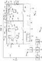
- Figs. 1 and 2show an exemplary embodiment of a building system related to the invention implemented in a portion of a building. More specifically, Fig. 1 shows a building system 100 in a portion or area 102 of a building that includes a communication network 104, a plurality of wireless nodes 106 within a building operably coupled to the communication network 104, a plurality of passive wireless devices 108a, 108b, ... 108n, and a processing circuit 110. In this embodiment, the building system 100 also includes sensor units 111 disposed through the building area 102.
- Fig. 2shows a schematic block diagram of the building system 100 of Fig. 1 apart from the building area 102.
- the building area 102includes a first space 112 in the form of an office, a second space 114 in the form of a conference room, and a third space 116 in the form of a hallway.
- the specifics of the layout of the building area 102 and spaces 112, 114 and 116are given by way of example only for the purposes of exposition. Those of ordinary skill in the art may readily adapt the principles described herein to any number of building layouts.
- the first space 112includes a chair 142, walls 144-147, a computer workstation 148, a telephone set 150, a window 154 and a desk 156.
- a ventilation damper 158is disposed above the ceiling space of the space 112, and is responsible for delivering conditioned air to the first space 112.
- the conditioned airmay be chilled air or heated air, and includes both recirculated and fresh air.
- the ventilation damper 158receives the conditioned air from air handling units and ventilation ducts, not shown, but which are known in the art.
- the ventilation damper 158may be used to control the temperature and/or fresh air content of the first space 112.
- a controllernot shown provides control output signals to the ventilation damper 158 to further open or close the damper 158 responsive to sensed conditions within the first space 112 and other factors.
- the second space 114includes fours chair 162-165, four walls 166-168, 147 (shared wall), a conference table 170, a side table 172, a desk lamp 174 and a window 176.
- a ventilation damper 178is disposed above the ceiling space of the space 114.
- the ventilation damper 178operates in substantially the same manner as the damper 158 of the first space 112.
- the ventilation damper 178is configured to deliver controlled amounts of conditioned air to the second space 114.
- the third space 116includes three wall segments 146, 166 and 180, a photocopier device 182, and a ventilation damper 184.
- the ventilation damper 184is disposed above the ceiling space or plenum of the space 116, and operates in substantially the same manner as the damper 158 of the first space 112.
- the ventilation damper 184is configured to deliver controlled amounts of conditioned air to the third space 116.
- each passive wireless device 108xis affixed to or within an object within the building area 102.
- the objectmay be a fixture, such as on a wall, window, carpeting, structural beams, HVAC structures, overhead lighting, and electrical and plumbing fixtures.
- the objectmay be a furnishing, such as tables, lamps, chairs, desks, window treatments and the like.
- the objectmay be electrical in nature, such as photocopiers, printers, telephones, lamps and lights.
- all of such objectshave a passive wireless device 108x.
- the passive wireless devices 108a, 108b, 108c and 108dare disposed on the four walls 144, 145, 146 and 147 of the first space 112
- the passive wireless devices 108e, 108fare disposed, respectively, on the chair 142 and desk 156 of the first space 112
- the passive wireless devices 108g, 108hare disposed on the windows 154, 176 of the first and second spaces 112, 114
- the passive wireless devices 108i, 108jare disposed respectively, the computer workstation 148 and telephone set 150 of the first space 112.
- Other passive wireless devicesare disposed on like objects within the building area 102.
- Each passive wireless device 108xcontains first information regarding at least one property of the object to which it is affixed.
- each passive wireless device 108xincludes information regarding a plurality of physical characteristics of the object to which it is attached. Such physical characteristics can include physical dimensions, thermal properties, manufacturer ID, object type ID, and date of manufacture, as well as subsets thereof. The physical characteristics can be specific to the type of object.
- the stored physical characteristics of an electrical devicesuch as the printer/copier 182, the computer 148 or telephone set 150 may include energy consumption information, and/or thermal energy (heat) generating properties.
- the stored physical characteristics of a window(e.g. 154, 176) may include optical properties and thermal properties.
- Each of the passive wireless devices 108xis configured to communicate wirelessly to at least one of the wireless nodes 106 using power derived from communication signals detected in the passive wireless device 108x.
- the passive wireless devices 108xmay suitably include so-called radio frequency identification (RFID) technology, which is known in the art.
- RFIDradio frequency identification
- the passive wireless device 108xreceives a signal from the wireless node 106 and transmits a response that includes stored data.
- the passive wireless device 108xharvests power from the received signal to perform the responsive transmission.
- RFIDradio frequency identification
- Fig. 3shows a block schematic diagram of an exemplary embodiment of a passive wireless device 108x.
- the passive wireless device 108xincludes an antenna 301, an RF circuit 302, a power harvest circuit 304, and a data processing circuit 306.
- the antenna 301can take any suitable for form RF transmission and reception, and is operably connected to the RF circuit 302.
- the RF circuit 302is an RF receiver and transmitter that is configured to operated on frequencies typically used for RFID operations. Multiple bands are currently in use for RFID operation. Devices operating in these frequency ranges are known.
- the power harvest circuit 304is a circuit that is operably coupled to obtain energy from RF signals received by the RF circuit 302, and is configured to provide that energy as bias power for the data processing circuit 306 and the RF circuit 302.
- the data processing circuit 306includes a memory 308 that stores information regarding the object to which the passive wireless device 108x is attached. Such information may include physical dimensions of the object, the identification of the object, the manufacturer of the object, thermal, optical and/or electrical properties of the object, and the date of manufacture of the object.
- the memory 308can store information regarding the "carbon shadow" of the object.
- the carbon shadowis the "carbon footprint” of the object in relation to its manufacture, storage, delivery and installation into the building area 102. If the object is electrical in nature, its carbon footprint information may include information regarding the average power consumption of the object or other measure of its energy usage. Accordingly, it will be appreciated that the processing circuit 110 of Fig. 1 can be used to track the carbon footprint of the building based on the information stored in the passive wireless devices 108x.
- the passive wireless device 108xin general, it will be appreciated that the passive wireless device 108x can be a so-called battery-assisted passive RFID device wherein a battery is included for powering the data processing circuit 306. In such a device, the energy from received RF signals is still used for transmission of responsive signals via the RF circuit 302.
- the sensor units 111include sensors for various conditions monitored and/or controlled by building systems.
- the sensor units 111can include temperature sensors, air flow sensors, light sensors, volatile organic compound sensors, or the like.
- each of the sensor units 111is a wireless sensor unit that includes multiple sensors, including microelecromechanical systems (MEMS) sensors.
- MEMSmicroelecromechanical systems
- the sensor units 111preferably comprise the sensors used for normal building automation operations such as, for example, temperature and ventilation control.
- Fig. 4shows an exemplary configuration of a multi-purpose sensor unit 400 that may be used as one or more of the sensor units 111.
- the sensor unit 400is a microsystem that employs a suite of MEMS sensors 402 that can any measure any combination of temperature, air flow, humidity, light, CO 2 , volatile organic compounds (VOCs).
- the microsystem sensor unit 400may also incorporate processing circuitry 404, as well as radio frequency transmission circuitry 406.
- General examples of MEMS devices having processing circuitry and RF capabilityare discussed in U.S. patent application with Pub. No. 2004/0008651 A1 entitled “Building System with Reduced Wiring Requirements and Apparatus for Use Therein", filed Jan. 28, 2003, and U.S. patent application with Pub. No. 2004/0144849A1, filed Sep. 26, 2003 , entitled “Building Control System Using Integrated MEMS Device”.
- the wireless nodes 106are disposed throughout the building area 102. As illustrated in Fig. 2 , the wireless nodes 106 are configured to communicate wirelessly with the sensor units 111 and the passive wireless devices 108x. The wireless nodes 106 are preferably also configured to communicate with the processing circuit 110 via a communication network 104 that extends substantially throughout the building area 102.
- the communication network 104may suitably comprise an Ethernet-based network, a wireless LAN (WLAN), or a combination of both.
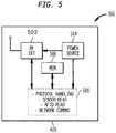
- Fig. 5shows an exemplary embodiment of a wireless node 106 that is configured for use with a communication network 104 in the form of a WLAN.
- the wireless node 106includes an RF communication circuit 502, a power source 504, a memory 506 and a processing circuit 508.
- the RF communication circuit 502includes an RF transmitter and receiver that is configured to controllably transmit and receive RF signals in the frequencies employed by the communication network 104, the sensor units 106, and the passive wireless devices 108x.
- the RF transceiver circuit 502is capable of transmitting and receiving wireless local area networks (WLANs), RFID tag signals, and Bluetooth signals.
- the RF communication circuit 502is further configured to demodulate the RF signals based on the one of the three wireless communication schemes being employed by the communication network 104, the sensor units 106, and the passive wireless devices 108x.
- the power source 504is a source of electrical power for use by the communication circuit 502, the memory 506 and the processing circuit 508.
- the power source 504may suitably include a long life lithium cell, or the like.
- electrical powermay also be derived from such a connection or another connection.
- the processing circuit 508includes circuitry for processing data transmitted using the three communication schemes employed by the communication network 104, the wireless sensor units 111, and the passive wireless devices 108x. Accordingly, the processing circuit 508 includes logic for protocol handling, as well as data formatting, for data received from the sensors 111, the passive wireless devices 108x, and the communication network 104. The processing circuit 508 further includes logic for controlling the operation of the RF communication circuit 502.
- the processing circuit 508is further programmed to carry out the operations (or to cause the elements 502 and 504 to carry out operations) attributed to the wireless node 106 as described herein.
- the processing circuit 508carries out operations stored as software code, which may be stored all or in part in the memory 506.
- the memory 506preferably also contains a list, table or data base that identifies the wireless passive devices 108x that have been previously detected by the wireless node 106. Such data enables the wireless node 106 to discover new passive wireless devices 108x, or detected when a passive wireless device 108x has been removed.
- the functionality of the wireless node 106 and the sensor unit 111can be combined into one device, at least in some circumstances.
- the wireless node 106could include controller functionality for an automation system, such as a controller for a ventilation damper, water valve, lighting fixture, or the like.
- the processing circuit 110 in this embodimentis part of a computer workstation 130 that includes a user interface 132, and a communication circuit 134.
- the processing circuit 110is also connected to data storage 136, which may or may not be all or partially included at the workstation 130.
- the data storage 136stores, among other things, a building data model 137, or building model 137, which can be generated or updated as described herein.
- the building data model 137is a database or other collection of data files that models the structures and operations of a building.
- the general architecture of such modelsis known, and typically include for each object in the model, its attributes and an identification of other objects in the model that it interacts with, or is connected to.
- the model 137differs from known building models by containing far more granular information about the building, including objects resulting from use of the building (such as furniture, equipment, and even occupancy), and the manner in which the model 137 is updated and used. Other differences will become readily apparent through the description.
- the processing circuit 110is operably coupled via the communication circuit 134 and network 104 to receive the information regarding the wireless devices 108x from the wireless nodes 106.
- the processing circuit 110is configured to update (or even generate) the building model 137 based at least in part on the information stored in the passive wireless devices 108x.
- the processing circuit 110can be used to enhance the building model 137 stored in the data store 136 by incorporating thermal properties obtained from passive wireless devices 108g, 108h affixed to windows 154, 176 in the building area 102. Such information can be used by simulation programs or planning programs that develop heating, cooling and ventilation strategies.
- the processing circuit 110may enhance the building model 137 by incorporating thermal (heat generating) properties obtained from the passive wireless devices 108i, 108j, affixed to electrical devices, such as the computer workstation 148 and the telephone set 150.
- the processing circuit 110is further configured to obtain information regarding the building conditions from the sensor units 111. Such information may be used for developing control strategies, adjusting real-time control operations, or providing a visualization (display) of the present conditions (or trends) within the building area 102.
- the processing circuit 110further employs the user interface 132 to display information regarding the model 137 and/or sensed conditions in the building 102. Because the processing circuit 110 has access to an accurate model 137 and to sensor values from the sensors 111, the processing circuit can provide intuitive displays of building layouts with information regarding the conditions sensed therein. Because the sensor units 111 in some embodiments are capable of sensing multiple environmental conditions, the processing circuit 110 can contemporaneously display information showing multiple conditions in a space within a displayed floor plan of the space, including objects located therein, if desired.
- wireless nodes 106, passive wireless devices 108x and processing circuit 110can provide multiple enhancements or improvements to building data models.
- the wireless nodes 106 and passive wireless devices 108xcan be used to help identify the location of new objects moved into a space, or a changed location of an existing object, thereby allowing for update of the building model 137. For example, if the wall 147 between the spaces 112 and 114 is moved two feet to the left, then the wireless nodes 106 can detect the movement through performing a location operation to determine the location of the passive wireless device 108d.
- Fig. 6shows a first set of operations that may be carried out in by the system 100.
- Fig. 6shows operations used by the system 100 to generate updates to a building model.
- the processing circuit 110obtains new data for the building model 137 stored in the data store 136 based on information generated using the passive wireless devices 108x.
- the informationincludes the identification and location of an object newly disposed at a location within the building area 102.
- the informationmay include obtaining other characteristics of the object from its passive wireless device, such as physical characteristics, carbon footprint information, and the like.
- Fig. 7shows an exemplary set of operations that may be used by the wireless nodes 106 and the passive wireless device 108x to obtain location, identification and other characteristics of a newly located object within the building area 102.
- a first wireless node 106sends probe RF signal to discover any passive wireless objects not previously detected. Such signals are intended to generate a substantially instantaneous response from passive wireless devices.
- the first wireless node 106receives a response signal from a passive wireless device 108x that has not been previously detected by the first wireless node 106.
- the first wireless node 106determines a distance d1 to the passive wireless device 108x, based on the time differential between transmission (step 702) and receipt of the response (step 704).
- the first wireless node 106may transmit a separate ranging signal to the new RFID device and determine the distance d1 based on the time differential between transmission of the ranging signal and receipt of the response from the new RFID device.
- a second wireless node 106also sends probe RF signal to discover any passive wireless objects not previously detected.
- the second wireless node 106receives a response signal from the new passive wireless device 108x.
- substantially every location within the building area 102is preferably within the wireless communication range of at least two wireless nodes 106. Accordingly, the placement of an object anywhere within the building area 102 results in at least two wireless nodes being able to detect the object's passive wireless device 108x.
- the first wireless node 106determines a distance d2 to the passive wireless device 108x, based on the time differential between transmission (step 708) and receipt of the response (step 710).
- a processing circuitdetermines the location of the new passive wireless device 108x based on d1, d2, the locations of the first and second wireless nodes 106, and other information.
- the other informationmay be another distance d3 to another wireless node 106, obtained in the same manner as d1 and d2.
- the additional distance value d3enables location via triangulation calculation.
- the other informationcan be information regarding the layout of the building area. For example, for any two wireless nodes 106 in Fig. 1 having determined distances d1, d2 to an unknown object, the intersection of d1, d2 will only define two points in a two-dimensional coordinate scheme. However, one of those two points will not be within the area 102.
- the processing circuitcan determine in step 712 the absolute location of a point, based on the two distances d1 and d2 from known locations of the wireless sensors, in a two-dimensional coordinate scheme. Such information is often sufficient even for three-dimensional coordinate schemes for objects that can safely be assumed to be located on the floor, such as tables, chairs, and large photocopiers. Otherwise, approximations are sufficient.
- the processing circuit that carries out step 714may suitably be the processing circuit 110. However, it will be appreciated that the processing circuit 508 of the one of the wireless nodes 106 may also carry this calculation, as well as other processing circuits.
- the first (or second) wireless nodeobtains any physical characterisitic information regarding the object based on the information stored in the memory of the passive wireless device 108x. While such information can be obtained in step 702 or 708, obtaining extensive information in those steps could interfere with the ability to obtain a proper distance measurement because there can be a delay introduced by retrieving information from the memory 308 of the passive wireless device 108x. Thus, obtaining stored information in a separate step allows for a simplified distance measurement probe signal in steps 702 and 708.
- step 602the processing circuit 110 performs step 604.
- step 604the processing circuit 110 updates the building model 137.
- the processing circuit 110may first add the object to the building model file, and then link the object to the model 137 based on the location information and/or other information.
- the processing circuit 110may also add other logical links, such as the logical position of the object in a system, such as an HVAC or fire system, if applicable.
- Methods of adding new elements to an existing building model using the object ID, the object location, and preferably physical dimensionsare known. Properties such as thermal properties, age, electrical properties and the like may be added if they are 1) supported by the model 137 and 2) provided by the passive wireless sensor 108x.
- the processing circuit 110receives any information regarding objects within the building model 137 that have been moved within, or removed from, the area 102.
- the various wireless nodes 106are configured to periodically check to see if objects previously detected by the nodes 106 are still detectable. Location of previously detected objects may be re-verified using a process similar to that described above in connection with Fig. 7 . If the nodes 106 (and processing circuit 110) detect that an object device that is currently in the building model 137 has been moved within the area 102 or completely removed, then the nodes 106 notify the processing circuit 110. In step 606, the processing circuit 110 receives the notification. In step 608, the processing circuit 110 updates the building model 137 accordingly.
- Steps 602, 604, 606 and 608can be repeated until all new, newly moved, or removed devices have been processed to update the model 137.
- system 100 of Fig. 1provides a method in which a building model stored in a data store can be updated in an ongoing manner. This process can be used during phases of commissioning the building as well as during day to day operation of the building. Thus, the building model can be kept current without requiring significant amounts of manual data entry. Thus, in contrast to prior practices, the system 100 maintains a building model during ongoing operation of the building, long after the initial construction and commissioning of the building have been completed.
- the processing circuit 110is further configured to update the building model 137 with a representation of occupants within a building.
- the building model 137would thus include information regarding occupants and their location within the building area 100.
- the system 100 of Fig. 1may be enhanced to incorporate passive wireless devices 108x disposed on the occupants of a building.
- each person within a buildingmay be required to wear an identification (or other security) badge.
- a badgewould include an RFID device (passive wireless device 108x).
- the system 100may then use operations similar to those discussed above in connection with Figs. 6 and 7 to identify the presence and location of occupants within the building.
- the model 137may be updated to include a quasi-real time representation of the current occupancy of a building.
- the system 100can use operations similar to those of Figs. 6 and 7 to track or trend occupancy on an hourly, daily, weekly and/or seasonal basis. Using the locating operations of Fig. 7 , the occupancy may be trended on a room-by-room basis.
- Such informationmay be incorporated into the building model 137, or stored as a related database.
- the system 100 described aboveenhances intelligent building control by combining the ongoing, updated model 137 with building operation data, as well as occupancy trends. As discussed above, updated building models can assist in improved building control strategies.
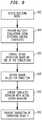
- the operations of Fig. 8show how the system 100 may be used to determine HVAC control strategies using simulation.
- the present embodimentfeatures generating simulations using a building model 137 with current and accurate thermal modeling information.
- the system 100can evaluate the accuracy of one or more simulations by using the sensor units 111 to detect the actual conditions of the system when a simulated control strategy is actually carried out.
- the thermal behavior of the occupantsmay also be incorporated into the simulation using the stored occupancy trend data.
- the processing circuit 110obtains access to the building model 137 that has been updated as described above.
- a modelprovides an accurate representation of all, or nearly all, objects within the building.
- the building model 137can include (or separately access) an occupancy model for each space 112, 114 and 116 of the building. As discussed above, such an occupancy model may be obtained by detecting occupants in real-time with the spaces 112, 114 and 116, and accumulating occupancy data over time.
- the processing circuitcauses multiple simulations to be performed.
- Each of the simulationscan specify conditions such as outdoor weather, the time of day, and the control strategy.
- multiple simulationsare performed by varying the control strategy, but using constant weather conditions.
- Various simulation methodsare known. These known simulation methods use the building model 137 to efficiently predict system behavior in response to a particular set of control operations. Because the model 137 as described herein can include thermal properties of various objects, such as electrical devices, windows, and can estimate the thermal contribution of occupants based on the occupancy trends, the simulation can be more comprehensive and accurate then previous simulation methods.
- the processing circuit 110can cause the HVAC system to perform control operations in accordance with a selected one of the simulations.
- analysis of the simulationsmay indicate a control strategy that is particularly efficient for a given set of circumstances (weather, time of day, season).
- the processing circuit 110 in step 806causes that control strategy to be implemented by the HVAC system.
- the processing circuit 110can communicate control strategy information to and HVAC control station, not shown, or directly to controllers, not shown, that control the ventilation dampers 158, 178 and 184.
- the processing circuit 110 and workstation 130also comprise a control station of one or more building automation systems.
- step 808the processing circuit 110 obtains values form sensor units 111 that identify the conditions in the building area 102 after the control strategy has been implemented.
- the sensor units 111communicate information regarding sensed conditions (temperature, humidity, CO 2 , VOCs, and/or flow) to the processing circuit 110 via the wireless nodes 106 and the network 112.
- step 810the processing circuit 110 compares the actual behavior of the system, based on the sensor information obtained in step 808, to the simulated behavior predicted in step 804.
- the simulationcan be granular, providing simulated behavior with respect to temperature and other conditions for each space 112, 114 and 116. Because the spaces 112, 114 and 116 have individual sensor units 111, the processing circuit 110 also has granular sensor data.
- the comparison in step 810can include a space by space analysis of the differences between the simulated behavior and the actual behavior.
- the processing circuit 110provides a visual indication of the results of the comparison, and at a minimum, and indication of where the simulation and the actual conditions varied significantly. A technician receiving such an indication may then determine the cause of the variance.
- a variance between a simulated behavior of an HVAC system and the actual behaviorcan be the result of errors in the building model 137.
- a variancecan indicate an equipment malfunction, or even equipment or structural components in need of maintenance. Accordingly, by displaying or otherwise indicating the existence and location of a significant variance between a simulated system performance and an actual system performance, maintenance issues in the building system can be discovered and corrected in a timely manner to help the system behave more efficiently.
- the processing circuit 110uses accumulated sensor values from the sensors 111 to develop granular trends of various sensed conditions in the spaces 112, 114 and 116.
- the processing circuit 110is further configured to correlate the sensed condition trends with occupancy trends within each space 112, 114, and 116.
- the processing circuit 110can then cause graphical or textual display of the result of the correlation.
- the processing circuit 110may identify a correlation in VOCs during high usage times of the conference room space 114.
- the processing circuit 110displays such a correlation. With the information made known, investigative and/or corrective action may be taken.
- the processing circuit 110may employ the same methods to correlate sensed environmental conditions with characteristics of objects in the building based on the information in the model 137.
- the processing circuit 110is configured to determine correlations between particular environmental conditions sensed by the sensor units 111 and physical characteristics of objects in a space as stored in the model 137.
- the processing circuit 110may identify a correlation between a certain manufacture of carpet (from the model 137) and excessive VOCs (as sensed by sensor units 111), or excessive heat in areas that include a certain model of photocopier.
- the processing circuit 110provides a display of such correlations so that further analysis, investigation, and/or corrective action can be taken.
- Fig. 9shows a different set of operations that may be carried out using the structures of the system 100.
- a ventilation dampere.g. dampers 158, 178 and 184
- a field controller or field panelsuch as a Siemens model TEC controller.
- the field controllersare typically located near, but not necessarily in the same room as, the ventilation damper it controls.
- Fig. 6 and 7can be used to identify the physical location and other properties of a newly installed damper.
- the methods of Figs. 6 and 7cannot necessarily be used to identify which controller is responsible for controlling the operation of the ventilation damper, as that is an installation issue. It is not likely that an installation technician would have the responsibility or capability of updating a passive wireless device 108x on a damper to indicate how it is connected to the HVAC system.
- the processing circuit 110can identify and locate the new damper, but cannot "connect" the damper to a field controller within the building model 137.
- a large open area in an office complexmay include multiple zones having multiple dampers and two or more field controllers.
- Fig. 10shows a situation in which the three dampers 158, 178 and 184 are possibly controlled by two controllers 1008 and 1010. While the individuals that installed the dampers 158, 178 and 184 would likely know which controllers specifically control each of the dampers, such information is not stored on their respective passive wireless devices 108x, and thus is not readily available for updating the building model 137. Even if the HVAC system has very clear identification of the controller that controls each damper, the physical location of such controller may not be stored in a format readily usable by a building model.
- Fig. 9The operations of Fig. 9 are employed to help determine which controller (as identified in the building model 137) controls a particular damper within the system 100. For example, consider an example in which the processing circuit 110 attempts to determine the controller that controls the damper 158.
- the processing circuitidentifies a plurality of controllers, e.g. controllers 1008, 1010 that are within a predefined distance to the damper in question, e.g. damper 158.
- the processing circuit 110identifies these controllers using the location information for the controllers and the damper 158.
- the locationmay suitably be obtained from the building model 137, generated as described herein. For example, the locations of the dampers 158, 178 and 184 and the controllers 1008, 1010 would have been determined using the operations of Fig. 7 .
- step 904the processing circuit 110 identifies the N controllers that are closest to the damper, e.g. damper 158.
- the number Nmay suitably be four. In the example described herein, only two controllers 1008 and 1010 are candidates, and therefore step 904 is not necessary. However, in the event that many controllers are within the "predefined" distance of a controller in question, the processing circuit 110 limits the candidate controllers to the closest N controllers.
- the processing circuit 110then, in step 906, sequentially causes each of the selected N controllers to change the flow of chilled air (or heated air) in a defined manner.
- each controllergenerates an output signal that causes its attached damper or dampers to open or close, thereby allow more or less condition air.
- Such an operationis intended to alter the temperature in the particular space in which the damper 158 is located. If a particular controller controls the damper 158, then the more or less chilled (or heated) air would be admitted to the space as a result of the changed output signal. If, however, a particular controller does not control the damper 158, then the temperature near the damper 158 will not be affect much, if at all.
- step 908the processing circuit 110 obtains sensor measurements from the sensor unit 111 closest to the damper in question, i.e. damper 158.
- the processing circuit 110records the sensor output corresponding to the times when each of the selected controllers altered its respective output flow signal to its connected dampers. As discussed above, if a candidate controller is configured to control the damper 158, then a significant temperature change will be detected. However, if a candidate controller is configured to control some other damper, then the measured temperature near the damper 158 will not be effected.
- step 910the processing circuit 110 identifies the controller that most affected the temperature in the vicinity of the damper 158.
- step 912the processing circuit 110 stores in the building model 137 a link between the damper 158 and the identified controller.
Landscapes
- Engineering & Computer Science (AREA)
- Computer Networks & Wireless Communication (AREA)
- Signal Processing (AREA)
- Automation & Control Theory (AREA)
- General Health & Medical Sciences (AREA)
- Medical Informatics (AREA)
- Health & Medical Sciences (AREA)
- Computing Systems (AREA)
- Human Computer Interaction (AREA)
- Computer Security & Cryptography (AREA)
- Air Conditioning Control Device (AREA)
- Mobile Radio Communication Systems (AREA)
- Selective Calling Equipment (AREA)
Description
- The present invention relates to building systems, building data modeling, and building automation.
- Building information modeling has been employed to assist in planning and implementation of various building systems. For example, it is known to provide building models during the development stage of a building project to aid in the selection of equipment, and to assist in formulating a construction plan. A building model will often contain granular details about the structural elements of a building, such as framing details, foundation details, wall details and the like.
- Existing building information models contain data identifying the two-dimensional or three-dimensional interrelationships among elements. Building models are typically stored as databases, and can be used by third parties for many purposes. While basic building construction can be planned and implemented using the building model, the building model can have additional purposes, such as for use in thermal load simulation analysis, or electrical power load simulation analysis.
- As construction progresses, further detail regarding the building becomes available, and in some cases, variations from the model occur. For example, during the construction process, equipment is selected, and details regarding ventilation, heating, plumbing, electrical and other elements are identified. The building model can be enhanced based on these additional details, providing a more comprehensive and accurate model.
- Historically, maintenance of the building model becomes more difficult and time-consuming as the building process progresses. Because the actual construction involves several subcontractors, each with several employees, it is difficult to update the building model in a comprehensive and reliable manner. As a result, the building model is often somewhat obsolete and has limited utility and reliability once the building has been constructed and is in use.
In this context,US 2006/185818 A1 e.g. describes a control system provided for automatically setting up and controlling a climate control system for a building having one or more zones and one or more thermostats in communication with the associated heating or cooling components of the climate control system.US 2006/0202834 A1 discloses a method to easily retrieve real-time information from a large number of sensors connected to a network, such as e.g. a control system network in buildings. In order to know an exact location of a functional device in a control system network, the location or position may be determined using a wireless distance measurement as disclosed inUS 2006/0074494 A1 . However, none of the prior art documents is able to teach the use of a building control network when setting up the operation of a wireless functional device within the network. Such installation or setup typically requires the knowledge of the link between the wireless device and the correct controller. - When setting up or replacing a new wireless device, it is not immediately obvious to the central control network which controller is responsible for the wireless device.
- Accordingly, there is a need for a method to identify the correct controller for a wireless device in such a building control network.
- The present invention addresses the above need, as well as others, by providing a method for identifying the controller for a ventilation damper in a building network.. The inventive method comprises:
- a) using a processing circuit operably coupled to a wireless device to identify a plurality N of controllers disposed within a predefined distance to a damper in a space;
- b) select one of the plurality of N controllers;
- c) obtain a temperature measurement within the space with a sensor unit;
- d) cause the selected controller to change the flow of conditioned air into the space by generating an output signal that causes the damper or dampers for which the controller is responsible to open or close, thereby allowing more or less conditioned air to flow out;
- e) after a first duration of time, obtain an updated temperature measurement with said sensor unit within the space;
- f) select other controllers of the plurality of N controllers, and for each of the other controllers of the plurality N, sequentially repeat steps c), d) and e);
- g) identify the controller from the plurality N that most affected the temperature in the vicinity of the damper.
- A related building system typically includes a communication network, a plurality of wireless nodes, a plurality of passive wireless devices, a plurality of sensors, and a processing circuit. The wireless nodes are disposed within a building and are operably coupled to the communication network. Each passive wireless device is affixed to an object within the building, and contains first information regarding at least one property of the object. Each the passive wireless device is configured to communicate wirelessly to the wireless nodes using power derived from communication signals detected in the passive wireless device. The sensors are configured to generate second information representative of sensed temperature throughout the building, each sensor operably connected to the communication network. The processing circuit is operably coupled to receive the first information from the wireless devices and the second information from the sensors. The processing circuit is configured to generate control information regarding the building based on the first information and the second information.
- The above described features and advantages, as well as others, will become more readily apparent to those of ordinary skill in the art by reference to the following detailed description and accompanying drawings.
Fig. 1 shows an exemplary embodiment of a building system related to the invention in a portion or area of a building.Fig. 2 shows a schematic block diagram of the building system ofFig. 1 apart from the building.Fig. 3 shows a block schematic diagram of an exemplary embodiment of a passive wireless device that may be used in the building system ofFig. 1 .Fig. 4 shows a block schematic diagram of an exemplary embodiment of a sensor unit that may be used in the building system ofFig. 1 .Fig. 5 shows a block schematic diagram of an exemplary embodiment of a wireless node that may be used in the building system ofFig. 1 .Fig. 6 shows a first set of operations that may be carried out in by the system ofFig. 1 .Fig. 7 shows an exemplary set of operations that may be used by the wireless nodes and the passive wireless device obtain location, identification and other characteristics of a newly located object within a building space.Fig. 8 shows an exemplary set of operations for simulating control strategies using a building model generated at least in part using the system ofFig. 1 .Fig. 9 shows a second set of operations that may be carried out in by the system ofFig. 1 according to an embodiment of the present invention.Fig. 10 shows an exemplary layout of controllers, ventilation dampers and sensors in the building area shownFig. 1 .Figs. 1 and2 show an exemplary embodiment of a building system related to the invention implemented in a portion of a building. More specifically,Fig. 1 shows abuilding system 100 in a portion orarea 102 of a building that includes acommunication network 104, a plurality ofwireless nodes 106 within a building operably coupled to thecommunication network 104, a plurality of passivewireless devices processing circuit 110. In this embodiment, thebuilding system 100 also includessensor units 111 disposed through thebuilding area 102.Fig. 2 shows a schematic block diagram of thebuilding system 100 ofFig. 1 apart from thebuilding area 102.- Referring specifically to
Fig. 1 , thebuilding area 102 includes afirst space 112 in the form of an office, asecond space 114 in the form of a conference room, and athird space 116 in the form of a hallway. The specifics of the layout of thebuilding area 102 andspaces - The
first space 112 includes achair 142, walls 144-147, acomputer workstation 148, atelephone set 150, awindow 154 and adesk 156. Aventilation damper 158 is disposed above the ceiling space of thespace 112, and is responsible for delivering conditioned air to thefirst space 112. The conditioned air may be chilled air or heated air, and includes both recirculated and fresh air. Theventilation damper 158 receives the conditioned air from air handling units and ventilation ducts, not shown, but which are known in the art. In general, theventilation damper 158 may be used to control the temperature and/or fresh air content of thefirst space 112. To this end, a controller, not shown provides control output signals to theventilation damper 158 to further open or close thedamper 158 responsive to sensed conditions within thefirst space 112 and other factors. - The
second space 114 includes fours chair 162-165, four walls 166-168, 147 (shared wall), a conference table 170, a side table 172, adesk lamp 174 and awindow 176. Aventilation damper 178 is disposed above the ceiling space of thespace 114. Theventilation damper 178 operates in substantially the same manner as thedamper 158 of thefirst space 112. In particular, theventilation damper 178 is configured to deliver controlled amounts of conditioned air to thesecond space 114. - The
third space 116 includes threewall segments photocopier device 182, and aventilation damper 184. Theventilation damper 184 is disposed above the ceiling space or plenum of thespace 116, and operates in substantially the same manner as thedamper 158 of thefirst space 112. In particular, theventilation damper 184 is configured to deliver controlled amounts of conditioned air to thethird space 116. - Referring again generally to
Figs. 1 and2 , each passive wireless device 108x is affixed to or within an object within thebuilding area 102. The object may be a fixture, such as on a wall, window, carpeting, structural beams, HVAC structures, overhead lighting, and electrical and plumbing fixtures. The object may be a furnishing, such as tables, lamps, chairs, desks, window treatments and the like. The object may be electrical in nature, such as photocopiers, printers, telephones, lamps and lights. Preferably, all of such objects have a passive wireless device 108x. - By way of example, the
passive wireless devices walls first space 112, thepassive wireless devices 108e, 108f are disposed, respectively, on thechair 142 anddesk 156 of thefirst space 112, thepassive wireless devices windows second spaces passive wireless devices 108i, 108j are disposed respectively, thecomputer workstation 148 and telephone set 150 of thefirst space 112. Other passive wireless devices are disposed on like objects within thebuilding area 102. - Each passive wireless device 108x contains first information regarding at least one property of the object to which it is affixed. In a preferred embodiment, each passive wireless device 108x includes information regarding a plurality of physical characteristics of the object to which it is attached. Such physical characteristics can include physical dimensions, thermal properties, manufacturer ID, object type ID, and date of manufacture, as well as subsets thereof. The physical characteristics can be specific to the type of object. For example, the stored physical characteristics of an electrical device such as the printer/
copier 182, thecomputer 148 or telephone set 150 may include energy consumption information, and/or thermal energy (heat) generating properties. The stored physical characteristics of a window (e.g. 154, 176) may include optical properties and thermal properties. - Each of the passive wireless devices 108x is configured to communicate wirelessly to at least one of the
wireless nodes 106 using power derived from communication signals detected in the passive wireless device 108x. Thus, for the example, the passive wireless devices 108x may suitably include so-called radio frequency identification (RFID) technology, which is known in the art. The passive wireless device 108x receives a signal from thewireless node 106 and transmits a response that includes stored data. The passive wireless device 108x harvests power from the received signal to perform the responsive transmission. Such technologies are generally known. Fig. 3 shows a block schematic diagram of an exemplary embodiment of a passive wireless device 108x. The passive wireless device 108x includes anantenna 301, anRF circuit 302, apower harvest circuit 304, and adata processing circuit 306. Theantenna 301 can take any suitable for form RF transmission and reception, and is operably connected to theRF circuit 302. TheRF circuit 302 is an RF receiver and transmitter that is configured to operated on frequencies typically used for RFID operations. Multiple bands are currently in use for RFID operation. Devices operating in these frequency ranges are known. Thepower harvest circuit 304 is a circuit that is operably coupled to obtain energy from RF signals received by theRF circuit 302, and is configured to provide that energy as bias power for thedata processing circuit 306 and theRF circuit 302. Thedata processing circuit 306 includes amemory 308 that stores information regarding the object to which the passive wireless device 108x is attached. Such information may include physical dimensions of the object, the identification of the object, the manufacturer of the object, thermal, optical and/or electrical properties of the object, and the date of manufacture of the object.- In some embodiments, the
memory 308 can store information regarding the "carbon shadow" of the object. The carbon shadow is the "carbon footprint" of the object in relation to its manufacture, storage, delivery and installation into thebuilding area 102. If the object is electrical in nature, its carbon footprint information may include information regarding the average power consumption of the object or other measure of its energy usage. Accordingly, it will be appreciated that theprocessing circuit 110 ofFig. 1 can be used to track the carbon footprint of the building based on the information stored in the passive wireless devices 108x. - Referring again the passive wireless device 108x in general, it will be appreciated that the passive wireless device 108x can be a so-called battery-assisted passive RFID device wherein a battery is included for powering the
data processing circuit 306. In such a device, the energy from received RF signals is still used for transmission of responsive signals via theRF circuit 302. - Referring again to
Figs. 1 and2 , thesensor units 111 include sensors for various conditions monitored and/or controlled by building systems. For example, thesensor units 111 can include temperature sensors, air flow sensors, light sensors, volatile organic compound sensors, or the like. In one embodiment, each of thesensor units 111 is a wireless sensor unit that includes multiple sensors, including microelecromechanical systems (MEMS) sensors. Thesensor units 111 preferably comprise the sensors used for normal building automation operations such as, for example, temperature and ventilation control. Fig. 4 shows an exemplary configuration of a multi-purpose sensor unit 400 that may be used as one or more of thesensor units 111. The sensor unit 400 is a microsystem that employs a suite ofMEMS sensors 402 that can any measure any combination of temperature, air flow, humidity, light, CO2, volatile organic compounds (VOCs). The microsystem sensor unit 400 may also incorporateprocessing circuitry 404, as well as radiofrequency transmission circuitry 406. General examples of MEMS devices having processing circuitry and RF capability are discussed inU.S. patent application with Pub. No. 2004/0008651 A1 entitled "Building System with Reduced Wiring Requirements and Apparatus for Use Therein", filed Jan. 28, 2003, andU.S. patent application with Pub. No. 2004/0144849A1, filed Sep. 26, 2003 , entitled "Building Control System Using Integrated MEMS Device".- Referring again to
Fig 1 , thewireless nodes 106 are disposed throughout thebuilding area 102. As illustrated inFig. 2 , thewireless nodes 106 are configured to communicate wirelessly with thesensor units 111 and the passive wireless devices 108x. Thewireless nodes 106 are preferably also configured to communicate with theprocessing circuit 110 via acommunication network 104 that extends substantially throughout thebuilding area 102. Thecommunication network 104 may suitably comprise an Ethernet-based network, a wireless LAN (WLAN), or a combination of both. Fig. 5 shows an exemplary embodiment of awireless node 106 that is configured for use with acommunication network 104 in the form of a WLAN. However, it will be appreciated that other embodiments of thewireless node 106 would be configured to communicate via a network cable, and thus are only "wireless" in the sense that such nodes communicate withsensor units 111 and passive wireless devices 108x in a wireless manner. Referring to the embodiment ofFig. 5 , thewireless node 106 includes anRF communication circuit 502, apower source 504, amemory 506 and aprocessing circuit 508.- In the embodiment described herein, the
RF communication circuit 502 includes an RF transmitter and receiver that is configured to controllably transmit and receive RF signals in the frequencies employed by thecommunication network 104, thesensor units 106, and the passive wireless devices 108x. Thus, for example, theRF transceiver circuit 502 is capable of transmitting and receiving wireless local area networks (WLANs), RFID tag signals, and Bluetooth signals. TheRF communication circuit 502 is further configured to demodulate the RF signals based on the one of the three wireless communication schemes being employed by thecommunication network 104, thesensor units 106, and the passive wireless devices 108x. - The
power source 504 is a source of electrical power for use by thecommunication circuit 502, thememory 506 and theprocessing circuit 508. Thepower source 504 may suitably include a long life lithium cell, or the like. However, in an embodiment wherein thewireless node 106 connects physically to thecommunication network 104, electrical power may also be derived from such a connection or another connection. - In any event, the
processing circuit 508 includes circuitry for processing data transmitted using the three communication schemes employed by thecommunication network 104, thewireless sensor units 111, and the passive wireless devices 108x. Accordingly, theprocessing circuit 508 includes logic for protocol handling, as well as data formatting, for data received from thesensors 111, the passive wireless devices 108x, and thecommunication network 104. Theprocessing circuit 508 further includes logic for controlling the operation of theRF communication circuit 502. - In addition, the
processing circuit 508 is further programmed to carry out the operations (or to cause theelements wireless node 106 as described herein. To this end, theprocessing circuit 508 carries out operations stored as software code, which may be stored all or in part in thememory 506. Thememory 506 preferably also contains a list, table or data base that identifies the wireless passive devices 108x that have been previously detected by thewireless node 106. Such data enables thewireless node 106 to discover new passive wireless devices 108x, or detected when a passive wireless device 108x has been removed. - It will be appreciated that the functionality of the
wireless node 106 and thesensor unit 111 can be combined into one device, at least in some circumstances. In addition, it is noted thewireless node 106 could include controller functionality for an automation system, such as a controller for a ventilation damper, water valve, lighting fixture, or the like. - Referring again to
Figs. 1 and2 , theprocessing circuit 110 in this embodiment is part of acomputer workstation 130 that includes auser interface 132, and acommunication circuit 134. Theprocessing circuit 110 is also connected todata storage 136, which may or may not be all or partially included at theworkstation 130. Thedata storage 136 stores, among other things, abuilding data model 137, orbuilding model 137, which can be generated or updated as described herein. - The
building data model 137 is a database or other collection of data files that models the structures and operations of a building. The general architecture of such models is known, and typically include for each object in the model, its attributes and an identification of other objects in the model that it interacts with, or is connected to. In the embodiments described herein, themodel 137 differs from known building models by containing far more granular information about the building, including objects resulting from use of the building (such as furniture, equipment, and even occupancy), and the manner in which themodel 137 is updated and used. Other differences will become readily apparent through the description. - In general, the
processing circuit 110 is operably coupled via thecommunication circuit 134 andnetwork 104 to receive the information regarding the wireless devices 108x from thewireless nodes 106. Theprocessing circuit 110 is configured to update (or even generate) thebuilding model 137 based at least in part on the information stored in the passive wireless devices 108x. In a simplified example, theprocessing circuit 110 can be used to enhance thebuilding model 137 stored in thedata store 136 by incorporating thermal properties obtained frompassive wireless devices windows building area 102. Such information can be used by simulation programs or planning programs that develop heating, cooling and ventilation strategies. Likewise, theprocessing circuit 110 may enhance thebuilding model 137 by incorporating thermal (heat generating) properties obtained from thepassive wireless devices 108i, 108j, affixed to electrical devices, such as thecomputer workstation 148 and thetelephone set 150. - The
processing circuit 110 is further configured to obtain information regarding the building conditions from thesensor units 111. Such information may be used for developing control strategies, adjusting real-time control operations, or providing a visualization (display) of the present conditions (or trends) within thebuilding area 102. - The
processing circuit 110 further employs theuser interface 132 to display information regarding themodel 137 and/or sensed conditions in thebuilding 102. Because theprocessing circuit 110 has access to anaccurate model 137 and to sensor values from thesensors 111, the processing circuit can provide intuitive displays of building layouts with information regarding the conditions sensed therein. Because thesensor units 111 in some embodiments are capable of sensing multiple environmental conditions, theprocessing circuit 110 can contemporaneously display information showing multiple conditions in a space within a displayed floor plan of the space, including objects located therein, if desired. - The above described combination of
wireless nodes 106, passive wireless devices 108x andprocessing circuit 110 can provide multiple enhancements or improvements to building data models. In some embodiments, thewireless nodes 106 and passive wireless devices 108x can be used to help identify the location of new objects moved into a space, or a changed location of an existing object, thereby allowing for update of thebuilding model 137. For example, if thewall 147 between thespaces wireless nodes 106 can detect the movement through performing a location operation to determine the location of thepassive wireless device 108d. - To this end,
Fig. 6 shows a first set of operations that may be carried out in by thesystem 100.Fig. 6 shows operations used by thesystem 100 to generate updates to a building model. - In
step 602, theprocessing circuit 110 obtains new data for thebuilding model 137 stored in thedata store 136 based on information generated using the passive wireless devices 108x. The information includes the identification and location of an object newly disposed at a location within thebuilding area 102. In addition, the information may include obtaining other characteristics of the object from its passive wireless device, such as physical characteristics, carbon footprint information, and the like. Fig. 7 shows an exemplary set of operations that may be used by thewireless nodes 106 and the passive wireless device 108x to obtain location, identification and other characteristics of a newly located object within thebuilding area 102.- In
step 702, afirst wireless node 106 sends probe RF signal to discover any passive wireless objects not previously detected. Such signals are intended to generate a substantially instantaneous response from passive wireless devices. In step 704, thefirst wireless node 106 receives a response signal from a passive wireless device 108x that has not been previously detected by thefirst wireless node 106. Instep 706, thefirst wireless node 106 determines a distanced1 to the passive wireless device 108x, based on the time differential between transmission (step 702) and receipt of the response (step 704). Alternatively, thefirst wireless node 106 may transmit a separate ranging signal to the new RFID device and determine the distanced1 based on the time differential between transmission of the ranging signal and receipt of the response from the new RFID device. - In
step 708, asecond wireless node 106 also sends probe RF signal to discover any passive wireless objects not previously detected. Instep 710, thesecond wireless node 106 receives a response signal from the new passive wireless device 108x. To this end, it is noted that substantially every location within thebuilding area 102 is preferably within the wireless communication range of at least twowireless nodes 106. Accordingly, the placement of an object anywhere within thebuilding area 102 results in at least two wireless nodes being able to detect the object's passive wireless device 108x. Instep 712, thefirst wireless node 106 determines a distanced2 to the passive wireless device 108x, based on the time differential between transmission (step 708) and receipt of the response (step 710). - In step 714, a processing circuit determines the location of the new passive wireless device 108x based ond1, d2, the locations of the first and
second wireless nodes 106, and other information. The other information may be another distanced3 to anotherwireless node 106, obtained in the same manner asd1 andd2. The additional distance valued3 enables location via triangulation calculation. Alternatively, the other information can be information regarding the layout of the building area. For example, for any twowireless nodes 106 inFig. 1 having determined distancesd1, d2 to an unknown object, the intersection ofd1, d2 will only define two points in a two-dimensional coordinate scheme. However, one of those two points willnot be within thearea 102. Accordingly, the processing circuit can determine instep 712 the absolute location of a point, based on the two distancesd1 andd2 from known locations of the wireless sensors, in a two-dimensional coordinate scheme. Such information is often sufficient even for three-dimensional coordinate schemes for objects that can safely be assumed to be located on the floor, such as tables, chairs, and large photocopiers. Otherwise, approximations are sufficient. - The processing circuit that carries out step 714 may suitably be the
processing circuit 110. However, it will be appreciated that theprocessing circuit 508 of the one of thewireless nodes 106 may also carry this calculation, as well as other processing circuits. - In
step 716, the first (or second) wireless node obtains any physical characterisitic information regarding the object based on the information stored in the memory of the passive wireless device 108x. While such information can be obtained instep memory 308 of the passive wireless device 108x. Thus, obtaining stored information in a separate step allows for a simplified distance measurement probe signal insteps - It will be noted that other methods of identifying newly located passive wireless devices, determining their location, and obtaining the information about the object on which the passive wireless device is attached may be employed using the
wireless nodes 106. To this end, U.S. Patent ApplicationUS2006/0073794A1 describes a method in which location coordinates and information content of RFID tags in a building environment may be obtained. Referring again toFig. 6 , afterstep 602, theprocessing circuit 110 performsstep 604. Instep 604, theprocessing circuit 110 updates thebuilding model 137. For example, if the object is a new object in thebuilding area 102, such as new furniture, or a new compute workstation, theprocessing circuit 110 may first add the object to the building model file, and then link the object to themodel 137 based on the location information and/or other information. Theprocessing circuit 110 may also add other logical links, such as the logical position of the object in a system, such as an HVAC or fire system, if applicable. Methods of adding new elements to an existing building model using the object ID, the object location, and preferably physical dimensions are known. Properties such as thermal properties, age, electrical properties and the like may be added if they are 1) supported by themodel 137 and 2) provided by the passive wireless sensor 108x. - In
step 606, theprocessing circuit 110 receives any information regarding objects within thebuilding model 137 that have been moved within, or removed from, thearea 102. To this end, thevarious wireless nodes 106 are configured to periodically check to see if objects previously detected by thenodes 106 are still detectable. Location of previously detected objects may be re-verified using a process similar to that described above in connection withFig. 7 . If the nodes 106 (and processing circuit 110) detect that an object device that is currently in thebuilding model 137 has been moved within thearea 102 or completely removed, then thenodes 106 notify theprocessing circuit 110. Instep 606, theprocessing circuit 110 receives the notification. Instep 608, theprocessing circuit 110 updates thebuilding model 137 accordingly. Steps model 137. Accordingly,system 100 ofFig. 1 provides a method in which a building model stored in a data store can be updated in an ongoing manner. This process can be used during phases of commissioning the building as well as during day to day operation of the building. Thus, the building model can be kept current without requiring significant amounts of manual data entry. Thus, in contrast to prior practices, thesystem 100 maintains a building model during ongoing operation of the building, long after the initial construction and commissioning of the building have been completed.- It is further known that the presence of occupants can affect building behavior. Accordingly, in some embodiments of the
system 100, theprocessing circuit 110 is further configured to update thebuilding model 137 with a representation of occupants within a building. Thebuilding model 137 would thus include information regarding occupants and their location within thebuilding area 100. - To this end, the
system 100 ofFig. 1 may be enhanced to incorporate passive wireless devices 108x disposed on the occupants of a building. For example, each person within a building may be required to wear an identification (or other security) badge. Such a badge would include an RFID device (passive wireless device 108x). Thesystem 100 may then use operations similar to those discussed above in connection withFigs. 6 and7 to identify the presence and location of occupants within the building. Themodel 137 may be updated to include a quasi-real time representation of the current occupancy of a building. In the alternative, or in addition, thesystem 100 can use operations similar to those ofFigs. 6 and7 to track or trend occupancy on an hourly, daily, weekly and/or seasonal basis. Using the locating operations ofFig. 7 , the occupancy may be trended on a room-by-room basis. Such information may be incorporated into thebuilding model 137, or stored as a related database. - The
system 100 described above enhances intelligent building control by combining the ongoing, updatedmodel 137 with building operation data, as well as occupancy trends. As discussed above, updated building models can assist in improved building control strategies. - For example, the operations of
Fig. 8 show how thesystem 100 may be used to determine HVAC control strategies using simulation. In contrast to prior HVAC simulation techniques, the present embodiment features generating simulations using abuilding model 137 with current and accurate thermal modeling information. In addition, thesystem 100 can evaluate the accuracy of one or more simulations by using thesensor units 111 to detect the actual conditions of the system when a simulated control strategy is actually carried out. In addition, in contrast to prior art simulations, the thermal behavior of the occupants may also be incorporated into the simulation using the stored occupancy trend data. - Referring to
Fig. 8 , instep 802, the processing circuit 110 (or another processing circuit) obtains access to thebuilding model 137 that has been updated as described above. Such a model provides an accurate representation of all, or nearly all, objects within the building. In addition, optionally, thebuilding model 137 can include (or separately access) an occupancy model for eachspace spaces - In
step 804, the processing circuit causes multiple simulations to be performed. Each of the simulations can specify conditions such as outdoor weather, the time of day, and the control strategy. In one embodiment, multiple simulations are performed by varying the control strategy, but using constant weather conditions. Various simulation methods are known. These known simulation methods use thebuilding model 137 to efficiently predict system behavior in response to a particular set of control operations. Because themodel 137 as described herein can include thermal properties of various objects, such as electrical devices, windows, and can estimate the thermal contribution of occupants based on the occupancy trends, the simulation can be more comprehensive and accurate then previous simulation methods. - In
step 806, theprocessing circuit 110 can cause the HVAC system to perform control operations in accordance with a selected one of the simulations. To this end, analysis of the simulations may indicate a control strategy that is particularly efficient for a given set of circumstances (weather, time of day, season). Theprocessing circuit 110 instep 806 causes that control strategy to be implemented by the HVAC system. To this end, theprocessing circuit 110 can communicate control strategy information to and HVAC control station, not shown, or directly to controllers, not shown, that control theventilation dampers processing circuit 110 andworkstation 130 also comprise a control station of one or more building automation systems. - In
step 808, theprocessing circuit 110 obtains valuesform sensor units 111 that identify the conditions in thebuilding area 102 after the control strategy has been implemented. To this end, thesensor units 111 communicate information regarding sensed conditions (temperature, humidity, CO2, VOCs, and/or flow) to theprocessing circuit 110 via thewireless nodes 106 and thenetwork 112. - In
step 810, theprocessing circuit 110 compares the actual behavior of the system, based on the sensor information obtained instep 808, to the simulated behavior predicted instep 804. As discussed above, the simulation can be granular, providing simulated behavior with respect to temperature and other conditions for eachspace spaces individual sensor units 111, theprocessing circuit 110 also has granular sensor data. Thus, the comparison instep 810 can include a space by space analysis of the differences between the simulated behavior and the actual behavior. - In
step 812, theprocessing circuit 110 provides a visual indication of the results of the comparison, and at a minimum, and indication of where the simulation and the actual conditions varied significantly. A technician receiving such an indication may then determine the cause of the variance. A variance between a simulated behavior of an HVAC system and the actual behavior can be the result of errors in thebuilding model 137. Alternatively, a variance can indicate an equipment malfunction, or even equipment or structural components in need of maintenance. Accordingly, by displaying or otherwise indicating the existence and location of a significant variance between a simulated system performance and an actual system performance, maintenance issues in the building system can be discovered and corrected in a timely manner to help the system behave more efficiently. - In another operation that does not necessarily involve simulation, the
processing circuit 110 uses accumulated sensor values from thesensors 111 to develop granular trends of various sensed conditions in thespaces processing circuit 110 is further configured to correlate the sensed condition trends with occupancy trends within eachspace processing circuit 110 can then cause graphical or textual display of the result of the correlation. - In this manner, problems that manifest themselves in spaces during high occupancy times can be addressed. For example, the
processing circuit 110 may identify a correlation in VOCs during high usage times of theconference room space 114. Theprocessing circuit 110 displays such a correlation. With the information made known, investigative and/or corrective action may be taken. - Similarly, the
processing circuit 110 may employ the same methods to correlate sensed environmental conditions with characteristics of objects in the building based on the information in themodel 137. For example, theprocessing circuit 110 is configured to determine correlations between particular environmental conditions sensed by thesensor units 111 and physical characteristics of objects in a space as stored in themodel 137. For, example, theprocessing circuit 110 may identify a correlation between a certain manufacture of carpet (from the model 137) and excessive VOCs (as sensed by sensor units 111), or excessive heat in areas that include a certain model of photocopier. Theprocessing circuit 110 provides a display of such correlations so that further analysis, investigation, and/or corrective action can be taken. Fig. 9 shows a different set of operations that may be carried out using the structures of thesystem 100. In particular, one of the issues in the installation and maintenance of a building HVAC system is tracking how ventilation dampers (or other actuators) are controlled. In particular, a ventilation damper (e.g. dampers - When a damper is installed or replaced within a building, the methods of
Fig. 6 and7 can be used to identify the physical location and other properties of a newly installed damper. However, the methods ofFigs. 6 and7 cannot necessarily be used to identify which controller is responsible for controlling the operation of the ventilation damper, as that is an installation issue. It is not likely that an installation technician would have the responsibility or capability of updating a passive wireless device 108x on a damper to indicate how it is connected to the HVAC system. Thus, theprocessing circuit 110 can identify and locate the new damper, but cannot "connect" the damper to a field controller within thebuilding model 137. - For example, a large open area in an office complex may include multiple zones having multiple dampers and two or more field controllers.
Fig. 10 shows a situation in which the threedampers controllers dampers building model 137. Even if the HVAC system has very clear identification of the controller that controls each damper, the physical location of such controller may not be stored in a format readily usable by a building model. - The operations of
Fig. 9 are employed to help determine which controller (as identified in the building model 137) controls a particular damper within thesystem 100. For example, consider an example in which theprocessing circuit 110 attempts to determine the controller that controls thedamper 158. - In
step 902, the processing circuit identifies a plurality of controllers,e.g. controllers e.g. damper 158. Theprocessing circuit 110 identifies these controllers using the location information for the controllers and thedamper 158. The location may suitably be obtained from thebuilding model 137, generated as described herein. For example, the locations of thedampers controllers Fig. 7 . - In
step 904, theprocessing circuit 110 identifies the N controllers that are closest to the damper,e.g. damper 158. The numberN may suitably be four. In the example described herein, only twocontrollers processing circuit 110 limits the candidate controllers to the closest N controllers. - The
processing circuit 110 then, instep 906, sequentially causes each of the selected N controllers to change the flow of chilled air (or heated air) in a defined manner. As a result, each controller generates an output signal that causes its attached damper or dampers to open or close, thereby allow more or less condition air. - Such an operation is intended to alter the temperature in the particular space in which the
damper 158 is located. If a particular controller controls thedamper 158, then the more or less chilled (or heated) air would be admitted to the space as a result of the changed output signal. If, however, a particular controller does not control thedamper 158, then the temperature near thedamper 158 will not be affect much, if at all. - In
step 908, theprocessing circuit 110 obtains sensor measurements from thesensor unit 111 closest to the damper in question, i.e.damper 158. Theprocessing circuit 110 records the sensor output corresponding to the times when each of the selected controllers altered its respective output flow signal to its connected dampers. As discussed above, if a candidate controller is configured to control thedamper 158, then a significant temperature change will be detected. However, if a candidate controller is configured to control some other damper, then the measured temperature near thedamper 158 will not be effected. - In
step 910, theprocessing circuit 110 identifies the controller that most affected the temperature in the vicinity of thedamper 158. Instep 912, theprocessing circuit 110 stores in the building model 137 a link between thedamper 158 and the identified controller.
Claims (7)
- A method, comprising:a) using a processing circuit (110) operably coupled to a wireless device (108x) to identify a plurality N of controllers (1008, 1010) disposed within a predefined distance to a damper (158) in a space;b) select one of the plurality of N controllers (1008, 1010);c) obtain a temperature measurement within the space with a sensor unit (111);d) cause the selected controller (1008, 1010) to change the flow of conditioned air into the space by generating an output signal that causes the damper (158) or dampers for which the controller (1008, 1010) is responsible to open or close, thereby allowing more or less conditioned air to flow out;e) after a first duration of time, obtain an updated temperature measurement with said sensor unit (111) within the space;f) select other controllers (1008, 1010) of the plurality of N controllers (1008, 1010), and for each of the other controllers (1008, 1010) of the plurality N, sequentially repeat steps c), d) and e);g) identify the controller (1008, 1010) from the plurality N that most affected the temperature in the vicinity of the damper (158).
- The method of claim 1, wherein step a) further comprises employing a wireless node (106) disposed proximate the space to communicate with the wireless device (108x) on a controller (1008, 1010).
- The method of claim 1, further comprising, after step a) determining a distance between each of the controllers (1008, 1010) and the damper (158) within the space.
- The method of claim 3, further comprising, identifying the N candidate controllers (1008, 1010) based on the determined distance between each of the controllers (1008, 1010) and the damper (158).
- The method of claim 1, further comprising updating a building model (137) to link the damper (158) and the identified controller (1008, 1010).
- The method of claim 1, further comprising controlling the temperature in the space using the identified controller (1008, 1010).
- The method of one of the preceding claims,characterized in that the wireless device (108x) is a passive wireless device (108x).
Applications Claiming Priority (3)
| Application Number | Priority Date | Filing Date | Title |
|---|---|---|---|
| US9381608P | 2008-09-03 | 2008-09-03 | |
| EP09752542.2AEP2345206B8 (en) | 2008-09-03 | 2009-09-03 | Wireless building management system using a building model |
| PCT/US2009/055888WO2010028149A2 (en) | 2008-09-03 | 2009-09-03 | Wireless building management system and method using a building model |
Related Parent Applications (2)
| Application Number | Title | Priority Date | Filing Date |
|---|---|---|---|
| EP09752542.2ADivision-IntoEP2345206B8 (en) | 2008-09-03 | 2009-09-03 | Wireless building management system using a building model |
| EP09752542.2ADivisionEP2345206B8 (en) | 2008-09-03 | 2009-09-03 | Wireless building management system using a building model |
Publications (2)
| Publication Number | Publication Date |
|---|---|
| EP3121999A1 EP3121999A1 (en) | 2017-01-25 |
| EP3121999B1true EP3121999B1 (en) | 2019-08-07 |
Family
ID=41461075
Family Applications (4)
| Application Number | Title | Priority Date | Filing Date |
|---|---|---|---|
| EP16186768.4AActiveEP3121999B1 (en) | 2008-09-03 | 2009-09-03 | Method for regulating temperatures in a wireless building management system |
| EP09752542.2AActiveEP2345206B8 (en) | 2008-09-03 | 2009-09-03 | Wireless building management system using a building model |
| EP09792227.2AActiveEP2347543B1 (en) | 2008-09-03 | 2009-09-03 | Passive and active wireless building management system |
| EP16186770.0AActiveEP3122000B1 (en) | 2008-09-03 | 2009-09-03 | Controller setup method in a wireless building management system |
Family Applications After (3)
| Application Number | Title | Priority Date | Filing Date |
|---|---|---|---|
| EP09752542.2AActiveEP2345206B8 (en) | 2008-09-03 | 2009-09-03 | Wireless building management system using a building model |
| EP09792227.2AActiveEP2347543B1 (en) | 2008-09-03 | 2009-09-03 | Passive and active wireless building management system |
| EP16186770.0AActiveEP3122000B1 (en) | 2008-09-03 | 2009-09-03 | Controller setup method in a wireless building management system |
Country Status (8)
| Country | Link |
|---|---|
| US (2) | US8315839B2 (en) |
| EP (4) | EP3121999B1 (en) |
| KR (3) | KR20110082129A (en) |
| CN (2) | CN102204163B (en) |
| BR (3) | BRPI0918805A2 (en) |
| CA (4) | CA2979772C (en) |
| MX (2) | MX2011002358A (en) |
| WO (2) | WO2010028149A2 (en) |
Families Citing this family (72)
| Publication number | Priority date | Publication date | Assignee | Title |
|---|---|---|---|---|
| US7861969B2 (en) | 2007-05-24 | 2011-01-04 | The Boeing Company | Shaped composite stringers and methods of making |
| US7879276B2 (en) | 2007-11-08 | 2011-02-01 | The Boeing Company | Foam stiffened hollow composite stringer |
| US8540921B2 (en) | 2008-11-25 | 2013-09-24 | The Boeing Company | Method of forming a reinforced foam-filled composite stringer |
| US20100253156A1 (en)* | 2009-04-07 | 2010-10-07 | Jeffrey Iott | Sensor device powered through rf harvesting |
| US8500066B2 (en) | 2009-06-12 | 2013-08-06 | The Boeing Company | Method and apparatus for wireless aircraft communications and power system using fuselage stringers |
| US8570152B2 (en)* | 2009-07-23 | 2013-10-29 | The Boeing Company | Method and apparatus for wireless sensing with power harvesting of a wireless signal |
| US8617687B2 (en) | 2009-08-03 | 2013-12-31 | The Boeing Company | Multi-functional aircraft structures |
| JP5649590B2 (en)* | 2010-02-12 | 2015-01-07 | 三菱電機株式会社 | Air conditioning system management device |
| US8606374B2 (en)* | 2010-09-14 | 2013-12-10 | Nest Labs, Inc. | Thermodynamic modeling for enclosures |
| US8659392B2 (en)* | 2010-09-22 | 2014-02-25 | General Electric Company | System and method for determining the location of wireless sensors |
| US20120259594A1 (en)* | 2011-04-08 | 2012-10-11 | Azam Khan | Bim based 3-d visualization |
| US10586181B2 (en) | 2011-04-12 | 2020-03-10 | Autodesk, Inc. | Generation of occupant activities based on recorded occupant behavior |
| US9292972B2 (en) | 2011-05-17 | 2016-03-22 | Autodesk, Inc. | Occupant centric capture and visualization of building performance data |
| US9342928B2 (en) | 2011-06-29 | 2016-05-17 | Honeywell International Inc. | Systems and methods for presenting building information |
| US8760103B2 (en) | 2011-09-30 | 2014-06-24 | Honeywell International Inc. | Actuator power control circuit having fail-safe bypass switching |
| US9981529B2 (en) | 2011-10-21 | 2018-05-29 | Honeywell International Inc. | Actuator having a test mode |
| US8749182B2 (en) | 2011-11-08 | 2014-06-10 | Honeywell International Inc. | Actuator having an adjustable auxiliary output |
| US8922140B2 (en) | 2011-11-09 | 2014-12-30 | Honeywell International Inc. | Dual potentiometer address and direction selection for an actuator |
| US10113762B2 (en) | 2011-11-09 | 2018-10-30 | Honeywell International Inc. | Actuator having an adjustable running time |
| US8588983B2 (en) | 2011-11-09 | 2013-11-19 | Honeywell International Inc. | Actuator with diagnostics |
| US9041319B2 (en) | 2011-11-09 | 2015-05-26 | Honeywell International Inc. | Actuator having an address selector |
| CN102567922A (en)* | 2012-01-17 | 2012-07-11 | 南昌工程学院 | Construction project management system platform based on BIM (Building Information Modeling) network technology and application method of construction project management system |
| US9488994B2 (en)* | 2012-03-29 | 2016-11-08 | Honeywell International Inc. | Method and system for configuring wireless sensors in an HVAC system |
| US9519731B2 (en)* | 2012-08-01 | 2016-12-13 | Honeywell International Inc. | Determining a heating, ventilation, and air conditioning model for a building |
| TWI503781B (en)* | 2012-08-28 | 2015-10-11 | Webim Services Co Ltd | Stereo building model managing system and the method thereof |
| EP2704365B1 (en) | 2012-08-31 | 2016-02-03 | Nxp B.V. | Method for establishing control relationships, configuration device, networked device and computer program product |
| US9396293B2 (en) | 2012-11-06 | 2016-07-19 | Cenergistic Llc | Adjustment simulation method for energy consumption |
| KR20140096717A (en)* | 2013-01-29 | 2014-08-06 | 한국전자통신연구원 | BIM-based building energy management apparatus and method |
| US10216869B2 (en)* | 2013-05-10 | 2019-02-26 | Trane International Inc. | System and method for simulating multiple BACnet devices and objects |
| US9106171B2 (en) | 2013-05-17 | 2015-08-11 | Honeywell International Inc. | Power supply compensation for an actuator |
| US9727667B2 (en) | 2013-06-10 | 2017-08-08 | Honeywell International Inc. | Generating a three dimensional building management system |
| US9747610B2 (en) | 2013-11-22 | 2017-08-29 | At&T Intellectual Property I, Lp | Method and apparatus for determining presence |
| US9380425B2 (en) | 2013-12-05 | 2016-06-28 | At&T Mobility Ii Llc | Systems, methods, and computer-readable storage devices for generating and using a radio-frequency map of an area |
| CN104765329B (en)* | 2014-03-11 | 2019-02-05 | 北京博锐尚格节能技术股份有限公司 | A kind of 3D energy consumption methods of exhibiting, apparatus and system |
| US9571986B2 (en)* | 2014-05-07 | 2017-02-14 | Johnson Controls Technology Company | Systems and methods for detecting and using equipment location in a building management system |
| US10437448B2 (en)* | 2014-07-08 | 2019-10-08 | Honeywell International Inc. | System and method for auto-configuration of devices in building information model |
| US9732977B2 (en) | 2014-09-02 | 2017-08-15 | Johnson Controls Technology Company | Systems and methods for configuring and communicating with HVAC devices |
| US10291292B2 (en) | 2014-09-02 | 2019-05-14 | Johnson Controls Technology Company | Wireless sensor with near field communication circuit |
| EP4148589A1 (en)* | 2015-02-13 | 2023-03-15 | Eutech Cybernetic | Integration platform to enable operational intelligence and user journeys for smart cities and the internet of things |
| US10386800B2 (en) | 2015-02-24 | 2019-08-20 | Siemens Industry, Inc. | Variable air volume modeling for an HVAC system |
| US10274382B1 (en)* | 2015-03-12 | 2019-04-30 | Alarm.Com Incorporated | Proactive management of appliances |
| EP3274976A1 (en) | 2015-03-24 | 2018-01-31 | Carrier Corporation | Systems and methods for providing a graphical user interface indicating intruder threat levels for a building |
| CN107646118B (en)* | 2015-03-24 | 2022-04-15 | 开利公司 | System and method for determining RF sensor performance in relation to floor plans |
| DK3275204T3 (en) | 2015-03-24 | 2020-09-21 | Carrier Corp | SYSTEM AND METHOD FOR COLLECTING AND ANALYZING MULTI-DIMENSIONAL BUILDING INFORMATION |
| EP3274932A1 (en) | 2015-03-24 | 2018-01-31 | Carrier Corporation | Integrated system for sales, installation, and maintenance of building systems |
| CN107660299B (en) | 2015-03-24 | 2021-02-26 | 开利公司 | Floor plan based planning for building systems |
| US10230326B2 (en) | 2015-03-24 | 2019-03-12 | Carrier Corporation | System and method for energy harvesting system planning and performance |
| WO2016154326A1 (en) | 2015-03-24 | 2016-09-29 | Carrier Corporation | Floor plan coverage based auto pairing and parameter setting |
| WO2016154321A1 (en) | 2015-03-24 | 2016-09-29 | Carrier Corporation | Floor-plan based learning and registration of distributed devices |
| US10982868B2 (en) | 2015-05-04 | 2021-04-20 | Johnson Controls Technology Company | HVAC equipment having locating systems and methods |
| CA2931736C (en) | 2015-10-29 | 2022-04-19 | Trevor Boicey | Heat energy management system |
| DE102015120358A1 (en)* | 2015-11-25 | 2017-06-01 | Enervision Gmbh | Method for operating a room controller |
| US10606223B2 (en) | 2015-12-03 | 2020-03-31 | At&T Intellectual Property I, L.P. | Mobile-based environmental control |
| DE102016102402A1 (en)* | 2016-02-11 | 2017-08-17 | Rwe Effizienz Gmbh | Home automation system |
| US10278027B2 (en)* | 2016-05-03 | 2019-04-30 | Johnson Controls Technology Company | Targeted alert system with location-based and role-based alert distribution |
| US10481574B2 (en)* | 2016-05-04 | 2019-11-19 | Johnson Controls Technology Company | Building alarm management system with mobile device notifications |
| US10402360B2 (en)* | 2016-06-10 | 2019-09-03 | Johnson Controls Technology Company | Building management system with automatic equipment discovery and equipment model distribution |
| US9905126B2 (en)* | 2016-06-14 | 2018-02-27 | Intel Corporation | Home environment management method and apparatus |
| US10642598B2 (en) | 2017-10-06 | 2020-05-05 | Johnson Controls Technology Company | Building management system with plug and play device registration and configuration |
| US11368534B2 (en) | 2017-10-06 | 2022-06-21 | Johnson Controls Tyco IP Holdings LLP | Building management system with device cloud registration and data adaptor |
| US11262741B2 (en) | 2017-10-06 | 2022-03-01 | Johnson Controls Tyco IP Holdings LLP | Building management system with automatic binding of equipment data |
| US11360468B2 (en) | 2017-10-06 | 2022-06-14 | Johnson Controls Tyco IP Holdings LLP | Building management system with cloud-based timeseries service |
| US12063124B2 (en) | 2017-10-06 | 2024-08-13 | Tyco Fire & Security Gmbh | Building management system with adapting IoT hub |
| CN111562745A (en)* | 2019-02-14 | 2020-08-21 | 开利公司 | Intelligent control system and intelligent control method |
| US12270561B2 (en)* | 2019-07-16 | 2025-04-08 | Tyco Fire & Security Gmbh | Systems and methods for automated system identification |
| US11774122B2 (en)* | 2019-07-16 | 2023-10-03 | Johnson Controls Tyco IP Holdings LLP | Building control system with adaptive online system identification |
| US12301661B2 (en)* | 2019-12-06 | 2025-05-13 | Zurn Water, Llc | Water management system and user interface |
| US11402813B2 (en)* | 2020-01-06 | 2022-08-02 | Honeywell International Inc. | Wall mountable universal backplane |
| US11108865B1 (en) | 2020-07-27 | 2021-08-31 | Zurn Industries, Llc | Battery powered end point device for IoT applications |
| US11480358B2 (en) | 2021-02-25 | 2022-10-25 | Synapse Wireless, Inc. | Machine learning systems for modeling and balancing the activity of air quality devices in industrial applications |
| CN113705463B (en)* | 2021-08-30 | 2024-02-20 | 安徽大学 | Factory footprint extraction method and system based on multi-scale gate control intensive connection |
| US11555734B1 (en) | 2022-02-18 | 2023-01-17 | Zurn Industries, Llc | Smart and cloud connected detection mechanism and real-time internet of things (IoT) system management |
Family Cites Families (34)
| Publication number | Priority date | Publication date | Assignee | Title |
|---|---|---|---|---|
| US6389010B1 (en)* | 1995-10-05 | 2002-05-14 | Intermec Ip Corp. | Hierarchical data collection network supporting packetized voice communications among wireless terminals and telephones |
| US6922558B2 (en)* | 1998-03-06 | 2005-07-26 | Don Delp | Integrated building control and information system with wireless networking |
| US6944622B1 (en)* | 2000-01-20 | 2005-09-13 | International Business Machines Corporation | User interface for automated project management |
| US7010594B2 (en)* | 2000-05-26 | 2006-03-07 | Isochron, Llc | System using environmental sensor and intelligent management and control transceiver for monitoring and controlling remote computing resources |
| US6971063B1 (en)* | 2000-07-28 | 2005-11-29 | Wireless Valley Communications Inc. | System, method, and apparatus for portable design, deployment, test, and optimization of a communication network |
| JP3790159B2 (en)* | 2001-12-27 | 2006-06-28 | 日立エンジニアリング株式会社 | Wireless communication system |
| AU2003210706A1 (en) | 2002-01-28 | 2003-09-02 | Siemens Building Technologies, Inc. | Building system with reduced wiring requirements and apparatus for use therein |
| US6718277B2 (en)* | 2002-04-17 | 2004-04-06 | Hewlett-Packard Development Company, L.P. | Atmospheric control within a building |
| US7295960B2 (en)* | 2003-01-22 | 2007-11-13 | Wireless Valley Communications, Inc. | System and method for automated placement or configuration of equipment for obtaining desired network performance objectives |
| US7295119B2 (en)* | 2003-01-22 | 2007-11-13 | Wireless Valley Communications, Inc. | System and method for indicating the presence or physical location of persons or devices in a site specific representation of a physical environment |
| US20040144849A1 (en) | 2003-01-28 | 2004-07-29 | Osman Ahmed | Building control system using integrated MEMS devices |
| US20050194456A1 (en)* | 2004-03-02 | 2005-09-08 | Tessier Patrick C. | Wireless controller with gateway |
| US7512450B2 (en)* | 2004-03-25 | 2009-03-31 | Siemens Building Technologies, Inc. | Method and apparatus for generating a building system model |
| US7383148B2 (en)* | 2004-03-25 | 2008-06-03 | Siemens Building Technologies, Inc. | Method and apparatus for graphically displaying a building system |
| US7130720B2 (en)* | 2004-06-23 | 2006-10-31 | Fisher James L | Radio frequency enabled control of environmental zones |
| US7545267B2 (en) | 2004-09-17 | 2009-06-09 | Siemens Building Technologies, Inc. | Arrangement and method for product information interaction with building control system elements |
| US7378980B2 (en)* | 2004-09-29 | 2008-05-27 | Siemens Building Technologies, Inc. | Triangulation of position for automated building control components |
| US7382271B2 (en)* | 2004-09-29 | 2008-06-03 | Siemens Building Technologies, Inc. | Automated position detection for wireless building automation devices |
| CN1287726C (en)* | 2004-11-25 | 2006-12-06 | 中国科学院计算技术研究所 | Medical treatment monitoring system, apparatus and method based on wireless sensor network |
| US7455225B1 (en)* | 2005-02-22 | 2008-11-25 | Sabioso, Inc. | Method and system for monitoring and controlling goods while in transit |
| US7448435B2 (en)* | 2005-02-23 | 2008-11-11 | Emerson Electric Co. | System and method for controlling a multi-zone heating or cooling system |
| JP4885463B2 (en)* | 2005-03-03 | 2012-02-29 | 株式会社日立製作所 | Sensor network system, sensor data processing method and program |
| JP4335181B2 (en)* | 2005-07-27 | 2009-09-30 | シャープ株式会社 | Sensor network system and sensor device control method thereof |
| US20070115951A1 (en)* | 2005-11-22 | 2007-05-24 | Jeyhan Karaoguz | System and method providing location based wireless resource identification |
| US7965178B1 (en)* | 2005-09-26 | 2011-06-21 | Schmutter Bruce E | System and method for integrated facility and fireground management |
| WO2007042371A1 (en)* | 2005-10-14 | 2007-04-19 | Siemens Aktiengesellschaft | Device for controlling the room temperature in a building using a predictive control device |
| US7579955B2 (en)* | 2006-08-11 | 2009-08-25 | Intermec Ip Corp. | Device and method for selective backscattering of wireless communications signals |
| US7758407B2 (en)* | 2006-09-26 | 2010-07-20 | Siemens Industry, Inc. | Ventilation control based on occupancy |
| US8339096B2 (en)* | 2006-11-20 | 2012-12-25 | Semiconductor Energy Laboratory Co., Ltd. | Wireless power receiving device |
| US20090065596A1 (en)* | 2007-05-09 | 2009-03-12 | Johnson Controls Technology Company | Systems and methods for increasing building space comfort using wireless devices |
| US20080277486A1 (en)* | 2007-05-09 | 2008-11-13 | Johnson Controls Technology Company | HVAC control system and method |
| US7769888B2 (en)* | 2007-06-15 | 2010-08-03 | Silver Spring Networks, Inc. | Method and system for providing network and routing protocols for utility services |
| WO2009018215A1 (en)* | 2007-07-31 | 2009-02-05 | Johnson Controls Technology Company | Devices for receiving and using energy from a building environment |
| US7986701B2 (en)* | 2008-06-13 | 2011-07-26 | Honeywell International Inc. | Wireless building control system bridge |
- 2009
- 2009-09-03EPEP16186768.4Apatent/EP3121999B1/enactiveActive
- 2009-09-03EPEP09752542.2Apatent/EP2345206B8/enactiveActive
- 2009-09-03USUS12/553,753patent/US8315839B2/enactiveActive
- 2009-09-03EPEP09792227.2Apatent/EP2347543B1/enactiveActive
- 2009-09-03KRKR1020117007599Apatent/KR20110082129A/ennot_activeCeased
- 2009-09-03BRBRPI0918805Apatent/BRPI0918805A2/ennot_activeApplication Discontinuation
- 2009-09-03WOPCT/US2009/055888patent/WO2010028149A2/enactiveApplication Filing
- 2009-09-03MXMX2011002358Apatent/MX2011002358A/enactiveIP Right Grant
- 2009-09-03BRBRPI0918239-0Apatent/BRPI0918239B1/enactiveIP Right Grant
- 2009-09-03MXMX2011002355Apatent/MX2011002355A/enactiveIP Right Grant
- 2009-09-03CNCN200980143342.6Apatent/CN102204163B/enactiveActive
- 2009-09-03CACA2979772Apatent/CA2979772C/enactiveActive
- 2009-09-03KRKR1020117007799Apatent/KR101298563B1/enactiveActive
- 2009-09-03EPEP16186770.0Apatent/EP3122000B1/enactiveActive
- 2009-09-03CACA2735864Apatent/CA2735864C/enactiveActive
- 2009-09-03CACA2896430Apatent/CA2896430C/enactiveActive
- 2009-09-03BRBR122020001578-0Apatent/BR122020001578B1/enactiveIP Right Grant
- 2009-09-03WOPCT/US2009/055871patent/WO2010028135A2/enactiveApplication Filing
- 2009-09-03CACA2735865Apatent/CA2735865C/enactiveActive
- 2009-09-03CNCN2009801421556Apatent/CN102217231B/enactiveActive
- 2009-09-03KRKR1020167002499Apatent/KR101749005B1/enactiveActive
- 2009-09-03USUS12/553,802patent/US8326465B2/enactiveActive
Non-Patent Citations (1)
| Title |
|---|
| None* |
Also Published As
Similar Documents
| Publication | Publication Date | Title |
|---|---|---|
| EP3121999B1 (en) | Method for regulating temperatures in a wireless building management system | |
| CN109790991B (en) | Equipment management system, air conditioner management system, communication condition adjustment method | |
| KR101298188B1 (en) | An apparatus and method of configuring a device in a network | |
| US7953419B2 (en) | Method for integration of network nodes | |
| US20160327293A1 (en) | Hvac equipment having locating systems and methods | |
| US20090045939A1 (en) | Locating devices using wireless communications | |
| Wang et al. | Energy conservation through flexible HVAC management in large spaces: An IPS-based demand-driven control (IDC) system | |
| US11564300B2 (en) | Real time locating system having lighting control devices | |
| CN105629907B (en) | area control system and automatic configuration method thereof | |
| Peffer et al. | Writing controls sequences for buildings: from HVAC industry enclave to hacker’s weekend project | |
| KR20230115105A (en) | Internet of things integration device based on monitoring indoor environment | |
| KR102554606B1 (en) | Smart indoor air quality management system and method for automatically managing multiple air management devices based on measured indoor air quality | |
| Cowan et al. | Integrated Controls Package for High Performance Interior Retrofit [Slides] | |
| CN108351625A (en) | Gesture control of the building automation system component during installation and/or maintenance |
Legal Events
| Date | Code | Title | Description |
|---|---|---|---|
| PUAI | Public reference made under article 153(3) epc to a published international application that has entered the european phase | Free format text:ORIGINAL CODE: 0009012 | |
| STAA | Information on the status of an ep patent application or granted ep patent | Free format text:STATUS: THE APPLICATION HAS BEEN PUBLISHED | |
| AC | Divisional application: reference to earlier application | Ref document number:2345206 Country of ref document:EP Kind code of ref document:P | |
| AK | Designated contracting states | Kind code of ref document:A1 Designated state(s):AT BE BG CH CY CZ DE DK EE ES FI FR GB GR HR HU IE IS IT LI LT LU LV MC MK MT NL NO PL PT RO SE SI SK SM TR | |
| STAA | Information on the status of an ep patent application or granted ep patent | Free format text:STATUS: REQUEST FOR EXAMINATION WAS MADE | |
| 17P | Request for examination filed | Effective date:20170721 | |
| RBV | Designated contracting states (corrected) | Designated state(s):AT BE BG CH CY CZ DE DK EE ES FI FR GB GR HR HU IE IS IT LI LT LU LV MC MK MT NL NO PL PT RO SE SI SK SM TR | |
| STAA | Information on the status of an ep patent application or granted ep patent | Free format text:STATUS: EXAMINATION IS IN PROGRESS | |
| 17Q | First examination report despatched | Effective date:20180711 | |
| GRAP | Despatch of communication of intention to grant a patent | Free format text:ORIGINAL CODE: EPIDOSNIGR1 | |
| STAA | Information on the status of an ep patent application or granted ep patent | Free format text:STATUS: GRANT OF PATENT IS INTENDED | |
| RIC1 | Information provided on ipc code assigned before grant | Ipc:H04L 29/08 20060101ALI20190218BHEP Ipc:H04W 16/20 20090101ALI20190218BHEP Ipc:H04L 12/24 20060101AFI20190218BHEP Ipc:H04L 12/28 20060101ALN20190218BHEP | |
| INTG | Intention to grant announced | Effective date:20190318 | |
| GRAS | Grant fee paid | Free format text:ORIGINAL CODE: EPIDOSNIGR3 | |
| GRAA | (expected) grant | Free format text:ORIGINAL CODE: 0009210 | |
| STAA | Information on the status of an ep patent application or granted ep patent | Free format text:STATUS: THE PATENT HAS BEEN GRANTED | |
| AC | Divisional application: reference to earlier application | Ref document number:2345206 Country of ref document:EP Kind code of ref document:P | |
| AK | Designated contracting states | Kind code of ref document:B1 Designated state(s):AT BE BG CH CY CZ DE DK EE ES FI FR GB GR HR HU IE IS IT LI LT LU LV MC MK MT NL NO PL PT RO SE SI SK SM TR | |
| REG | Reference to a national code | Ref country code:GB Ref legal event code:FG4D | |
| REG | Reference to a national code | Ref country code:CH Ref legal event code:EP Ref country code:CH Ref legal event code:NV Representative=s name:SIEMENS SCHWEIZ AG, CH Ref country code:AT Ref legal event code:REF Ref document number:1165517 Country of ref document:AT Kind code of ref document:T Effective date:20190815 | |
| REG | Reference to a national code | Ref country code:DE Ref legal event code:R096 Ref document number:602009059424 Country of ref document:DE | |
| REG | Reference to a national code | Ref country code:IE Ref legal event code:FG4D | |
| REG | Reference to a national code | Ref country code:NL Ref legal event code:MP Effective date:20190807 | |
| REG | Reference to a national code | Ref country code:LT Ref legal event code:MG4D | |
| PG25 | Lapsed in a contracting state [announced via postgrant information from national office to epo] | Ref country code:PT Free format text:LAPSE BECAUSE OF FAILURE TO SUBMIT A TRANSLATION OF THE DESCRIPTION OR TO PAY THE FEE WITHIN THE PRESCRIBED TIME-LIMIT Effective date:20191209 Ref country code:BG Free format text:LAPSE BECAUSE OF FAILURE TO SUBMIT A TRANSLATION OF THE DESCRIPTION OR TO PAY THE FEE WITHIN THE PRESCRIBED TIME-LIMIT Effective date:20191107 Ref country code:SE Free format text:LAPSE BECAUSE OF FAILURE TO SUBMIT A TRANSLATION OF THE DESCRIPTION OR TO PAY THE FEE WITHIN THE PRESCRIBED TIME-LIMIT Effective date:20190807 Ref country code:NL Free format text:LAPSE BECAUSE OF FAILURE TO SUBMIT A TRANSLATION OF THE DESCRIPTION OR TO PAY THE FEE WITHIN THE PRESCRIBED TIME-LIMIT Effective date:20190807 Ref country code:HR Free format text:LAPSE BECAUSE OF FAILURE TO SUBMIT A TRANSLATION OF THE DESCRIPTION OR TO PAY THE FEE WITHIN THE PRESCRIBED TIME-LIMIT Effective date:20190807 Ref country code:LT Free format text:LAPSE BECAUSE OF FAILURE TO SUBMIT A TRANSLATION OF THE DESCRIPTION OR TO PAY THE FEE WITHIN THE PRESCRIBED TIME-LIMIT Effective date:20190807 Ref country code:FI Free format text:LAPSE BECAUSE OF FAILURE TO SUBMIT A TRANSLATION OF THE DESCRIPTION OR TO PAY THE FEE WITHIN THE PRESCRIBED TIME-LIMIT Effective date:20190807 Ref country code:NO Free format text:LAPSE BECAUSE OF FAILURE TO SUBMIT A TRANSLATION OF THE DESCRIPTION OR TO PAY THE FEE WITHIN THE PRESCRIBED TIME-LIMIT Effective date:20191107 | |
| REG | Reference to a national code | Ref country code:AT Ref legal event code:MK05 Ref document number:1165517 Country of ref document:AT Kind code of ref document:T Effective date:20190807 | |
| PG25 | Lapsed in a contracting state [announced via postgrant information from national office to epo] | Ref country code:ES Free format text:LAPSE BECAUSE OF FAILURE TO SUBMIT A TRANSLATION OF THE DESCRIPTION OR TO PAY THE FEE WITHIN THE PRESCRIBED TIME-LIMIT Effective date:20190807 Ref country code:GR Free format text:LAPSE BECAUSE OF FAILURE TO SUBMIT A TRANSLATION OF THE DESCRIPTION OR TO PAY THE FEE WITHIN THE PRESCRIBED TIME-LIMIT Effective date:20191108 Ref country code:IS Free format text:LAPSE BECAUSE OF FAILURE TO SUBMIT A TRANSLATION OF THE DESCRIPTION OR TO PAY THE FEE WITHIN THE PRESCRIBED TIME-LIMIT Effective date:20191207 Ref country code:LV Free format text:LAPSE BECAUSE OF FAILURE TO SUBMIT A TRANSLATION OF THE DESCRIPTION OR TO PAY THE FEE WITHIN THE PRESCRIBED TIME-LIMIT Effective date:20190807 | |
| PG25 | Lapsed in a contracting state [announced via postgrant information from national office to epo] | Ref country code:TR Free format text:LAPSE BECAUSE OF FAILURE TO SUBMIT A TRANSLATION OF THE DESCRIPTION OR TO PAY THE FEE WITHIN THE PRESCRIBED TIME-LIMIT Effective date:20190807 | |
| PG25 | Lapsed in a contracting state [announced via postgrant information from national office to epo] | Ref country code:IT Free format text:LAPSE BECAUSE OF FAILURE TO SUBMIT A TRANSLATION OF THE DESCRIPTION OR TO PAY THE FEE WITHIN THE PRESCRIBED TIME-LIMIT Effective date:20190807 Ref country code:RO Free format text:LAPSE BECAUSE OF FAILURE TO SUBMIT A TRANSLATION OF THE DESCRIPTION OR TO PAY THE FEE WITHIN THE PRESCRIBED TIME-LIMIT Effective date:20190807 Ref country code:AT Free format text:LAPSE BECAUSE OF FAILURE TO SUBMIT A TRANSLATION OF THE DESCRIPTION OR TO PAY THE FEE WITHIN THE PRESCRIBED TIME-LIMIT Effective date:20190807 Ref country code:PL Free format text:LAPSE BECAUSE OF FAILURE TO SUBMIT A TRANSLATION OF THE DESCRIPTION OR TO PAY THE FEE WITHIN THE PRESCRIBED TIME-LIMIT Effective date:20190807 Ref country code:EE Free format text:LAPSE BECAUSE OF FAILURE TO SUBMIT A TRANSLATION OF THE DESCRIPTION OR TO PAY THE FEE WITHIN THE PRESCRIBED TIME-LIMIT Effective date:20190807 Ref country code:DK Free format text:LAPSE BECAUSE OF FAILURE TO SUBMIT A TRANSLATION OF THE DESCRIPTION OR TO PAY THE FEE WITHIN THE PRESCRIBED TIME-LIMIT Effective date:20190807 | |
| PG25 | Lapsed in a contracting state [announced via postgrant information from national office to epo] | Ref country code:MC Free format text:LAPSE BECAUSE OF FAILURE TO SUBMIT A TRANSLATION OF THE DESCRIPTION OR TO PAY THE FEE WITHIN THE PRESCRIBED TIME-LIMIT Effective date:20190807 Ref country code:SK Free format text:LAPSE BECAUSE OF FAILURE TO SUBMIT A TRANSLATION OF THE DESCRIPTION OR TO PAY THE FEE WITHIN THE PRESCRIBED TIME-LIMIT Effective date:20190807 Ref country code:IS Free format text:LAPSE BECAUSE OF FAILURE TO SUBMIT A TRANSLATION OF THE DESCRIPTION OR TO PAY THE FEE WITHIN THE PRESCRIBED TIME-LIMIT Effective date:20200224 Ref country code:SM Free format text:LAPSE BECAUSE OF FAILURE TO SUBMIT A TRANSLATION OF THE DESCRIPTION OR TO PAY THE FEE WITHIN THE PRESCRIBED TIME-LIMIT Effective date:20190807 Ref country code:CZ Free format text:LAPSE BECAUSE OF FAILURE TO SUBMIT A TRANSLATION OF THE DESCRIPTION OR TO PAY THE FEE WITHIN THE PRESCRIBED TIME-LIMIT Effective date:20190807 | |
| REG | Reference to a national code | Ref country code:DE Ref legal event code:R097 Ref document number:602009059424 Country of ref document:DE | |
| PLBE | No opposition filed within time limit | Free format text:ORIGINAL CODE: 0009261 | |
| STAA | Information on the status of an ep patent application or granted ep patent | Free format text:STATUS: NO OPPOSITION FILED WITHIN TIME LIMIT | |
| PG2D | Information on lapse in contracting state deleted | Ref country code:IS | |
| PG25 | Lapsed in a contracting state [announced via postgrant information from national office to epo] | Ref country code:IE Free format text:LAPSE BECAUSE OF NON-PAYMENT OF DUE FEES Effective date:20190903 Ref country code:LU Free format text:LAPSE BECAUSE OF NON-PAYMENT OF DUE FEES Effective date:20190903 | |
| REG | Reference to a national code | Ref country code:BE Ref legal event code:MM Effective date:20190930 | |
| 26N | No opposition filed | Effective date:20200603 | |
| PG25 | Lapsed in a contracting state [announced via postgrant information from national office to epo] | Ref country code:SI Free format text:LAPSE BECAUSE OF FAILURE TO SUBMIT A TRANSLATION OF THE DESCRIPTION OR TO PAY THE FEE WITHIN THE PRESCRIBED TIME-LIMIT Effective date:20190807 Ref country code:BE Free format text:LAPSE BECAUSE OF NON-PAYMENT OF DUE FEES Effective date:20190930 | |
| PG25 | Lapsed in a contracting state [announced via postgrant information from national office to epo] | Ref country code:CY Free format text:LAPSE BECAUSE OF FAILURE TO SUBMIT A TRANSLATION OF THE DESCRIPTION OR TO PAY THE FEE WITHIN THE PRESCRIBED TIME-LIMIT Effective date:20190807 | |
| PG25 | Lapsed in a contracting state [announced via postgrant information from national office to epo] | Ref country code:MT Free format text:LAPSE BECAUSE OF FAILURE TO SUBMIT A TRANSLATION OF THE DESCRIPTION OR TO PAY THE FEE WITHIN THE PRESCRIBED TIME-LIMIT Effective date:20190807 Ref country code:HU Free format text:LAPSE BECAUSE OF FAILURE TO SUBMIT A TRANSLATION OF THE DESCRIPTION OR TO PAY THE FEE WITHIN THE PRESCRIBED TIME-LIMIT; INVALID AB INITIO Effective date:20090903 | |
| REG | Reference to a national code | Ref country code:DE Ref legal event code:R079 Ref document number:602009059424 Country of ref document:DE Free format text:PREVIOUS MAIN CLASS: H04L0012240000 Ipc:H04L0041000000 | |
| PG25 | Lapsed in a contracting state [announced via postgrant information from national office to epo] | Ref country code:MK Free format text:LAPSE BECAUSE OF FAILURE TO SUBMIT A TRANSLATION OF THE DESCRIPTION OR TO PAY THE FEE WITHIN THE PRESCRIBED TIME-LIMIT Effective date:20190807 | |
| PGFP | Annual fee paid to national office [announced via postgrant information from national office to epo] | Ref country code:FR Payment date:20240916 Year of fee payment:16 | |
| PGFP | Annual fee paid to national office [announced via postgrant information from national office to epo] | Ref country code:DE Payment date:20241118 Year of fee payment:16 | |
| PGFP | Annual fee paid to national office [announced via postgrant information from national office to epo] | Ref country code:GB Payment date:20241007 Year of fee payment:16 | |
| PGFP | Annual fee paid to national office [announced via postgrant information from national office to epo] | Ref country code:CH Payment date:20241203 Year of fee payment:16 |