EP3121789A1 - Method and system for convolutional neural network regression based 2d/3d image registration - Google Patents
Method and system for convolutional neural network regression based 2d/3d image registrationDownload PDFInfo
- Publication number
- EP3121789A1 EP3121789A1EP16180616.1AEP16180616AEP3121789A1EP 3121789 A1EP3121789 A1EP 3121789A1EP 16180616 AEP16180616 AEP 16180616AEP 3121789 A1EP3121789 A1EP 3121789A1
- Authority
- EP
- European Patent Office
- Prior art keywords
- transformation parameters
- parameter space
- lir
- features
- plane
- Prior art date
- Legal status (The legal status is an assumption and is not a legal conclusion. Google has not performed a legal analysis and makes no representation as to the accuracy of the status listed.)
- Granted
Links
Images


Classifications
- G—PHYSICS
- G06—COMPUTING OR CALCULATING; COUNTING
- G06T—IMAGE DATA PROCESSING OR GENERATION, IN GENERAL
- G06T7/00—Image analysis
- G06T7/30—Determination of transform parameters for the alignment of images, i.e. image registration
- G06T7/33—Determination of transform parameters for the alignment of images, i.e. image registration using feature-based methods
- G—PHYSICS
- G06—COMPUTING OR CALCULATING; COUNTING
- G06T—IMAGE DATA PROCESSING OR GENERATION, IN GENERAL
- G06T3/00—Geometric image transformations in the plane of the image
- G06T3/14—Transformations for image registration, e.g. adjusting or mapping for alignment of images
- G—PHYSICS
- G06—COMPUTING OR CALCULATING; COUNTING
- G06F—ELECTRIC DIGITAL DATA PROCESSING
- G06F18/00—Pattern recognition
- G06F18/20—Analysing
- G06F18/24—Classification techniques
- G06F18/241—Classification techniques relating to the classification model, e.g. parametric or non-parametric approaches
- G06F18/2415—Classification techniques relating to the classification model, e.g. parametric or non-parametric approaches based on parametric or probabilistic models, e.g. based on likelihood ratio or false acceptance rate versus a false rejection rate
- G—PHYSICS
- G06—COMPUTING OR CALCULATING; COUNTING
- G06N—COMPUTING ARRANGEMENTS BASED ON SPECIFIC COMPUTATIONAL MODELS
- G06N3/00—Computing arrangements based on biological models
- G06N3/02—Neural networks
- G06N3/04—Architecture, e.g. interconnection topology
- G—PHYSICS
- G06—COMPUTING OR CALCULATING; COUNTING
- G06N—COMPUTING ARRANGEMENTS BASED ON SPECIFIC COMPUTATIONAL MODELS
- G06N3/00—Computing arrangements based on biological models
- G06N3/02—Neural networks
- G06N3/04—Architecture, e.g. interconnection topology
- G06N3/0464—Convolutional networks [CNN, ConvNet]
- G—PHYSICS
- G06—COMPUTING OR CALCULATING; COUNTING
- G06N—COMPUTING ARRANGEMENTS BASED ON SPECIFIC COMPUTATIONAL MODELS
- G06N3/00—Computing arrangements based on biological models
- G06N3/02—Neural networks
- G06N3/08—Learning methods
- G—PHYSICS
- G06—COMPUTING OR CALCULATING; COUNTING
- G06N—COMPUTING ARRANGEMENTS BASED ON SPECIFIC COMPUTATIONAL MODELS
- G06N3/00—Computing arrangements based on biological models
- G06N3/02—Neural networks
- G06N3/08—Learning methods
- G06N3/09—Supervised learning
- G—PHYSICS
- G06—COMPUTING OR CALCULATING; COUNTING
- G06T—IMAGE DATA PROCESSING OR GENERATION, IN GENERAL
- G06T7/00—Image analysis
- G06T7/0002—Inspection of images, e.g. flaw detection
- G06T7/0012—Biomedical image inspection
- G—PHYSICS
- G06—COMPUTING OR CALCULATING; COUNTING
- G06T—IMAGE DATA PROCESSING OR GENERATION, IN GENERAL
- G06T2200/00—Indexing scheme for image data processing or generation, in general
- G06T2200/04—Indexing scheme for image data processing or generation, in general involving 3D image data
- G—PHYSICS
- G06—COMPUTING OR CALCULATING; COUNTING
- G06T—IMAGE DATA PROCESSING OR GENERATION, IN GENERAL
- G06T2207/00—Indexing scheme for image analysis or image enhancement
- G06T2207/10—Image acquisition modality
- G06T2207/10072—Tomographic images
- G06T2207/10081—Computed x-ray tomography [CT]
- G—PHYSICS
- G06—COMPUTING OR CALCULATING; COUNTING
- G06T—IMAGE DATA PROCESSING OR GENERATION, IN GENERAL
- G06T2207/00—Indexing scheme for image analysis or image enhancement
- G06T2207/10—Image acquisition modality
- G06T2207/10072—Tomographic images
- G06T2207/10088—Magnetic resonance imaging [MRI]
- G—PHYSICS
- G06—COMPUTING OR CALCULATING; COUNTING
- G06T—IMAGE DATA PROCESSING OR GENERATION, IN GENERAL
- G06T2207/00—Indexing scheme for image analysis or image enhancement
- G06T2207/10—Image acquisition modality
- G06T2207/10116—X-ray image
- G—PHYSICS
- G06—COMPUTING OR CALCULATING; COUNTING
- G06T—IMAGE DATA PROCESSING OR GENERATION, IN GENERAL
- G06T2207/00—Indexing scheme for image analysis or image enhancement
- G06T2207/10—Image acquisition modality
- G06T2207/10116—X-ray image
- G06T2207/10124—Digitally reconstructed radiograph [DRR]
- G—PHYSICS
- G06—COMPUTING OR CALCULATING; COUNTING
- G06T—IMAGE DATA PROCESSING OR GENERATION, IN GENERAL
- G06T2207/00—Indexing scheme for image analysis or image enhancement
- G06T2207/20—Special algorithmic details
- G06T2207/20021—Dividing image into blocks, subimages or windows
- G—PHYSICS
- G06—COMPUTING OR CALCULATING; COUNTING
- G06T—IMAGE DATA PROCESSING OR GENERATION, IN GENERAL
- G06T2207/00—Indexing scheme for image analysis or image enhancement
- G06T2207/20—Special algorithmic details
- G06T2207/20081—Training; Learning
- G—PHYSICS
- G06—COMPUTING OR CALCULATING; COUNTING
- G06T—IMAGE DATA PROCESSING OR GENERATION, IN GENERAL
- G06T2207/00—Indexing scheme for image analysis or image enhancement
- G06T2207/20—Special algorithmic details
- G06T2207/20084—Artificial neural networks [ANN]
- G—PHYSICS
- G06—COMPUTING OR CALCULATING; COUNTING
- G06T—IMAGE DATA PROCESSING OR GENERATION, IN GENERAL
- G06T2207/00—Indexing scheme for image analysis or image enhancement
- G06T2207/30—Subject of image; Context of image processing
- G06T2207/30004—Biomedical image processing
- G—PHYSICS
- G06—COMPUTING OR CALCULATING; COUNTING
- G06T—IMAGE DATA PROCESSING OR GENERATION, IN GENERAL
- G06T2207/00—Indexing scheme for image analysis or image enhancement
- G06T2207/30—Subject of image; Context of image processing
- G06T2207/30004—Biomedical image processing
- G06T2207/30052—Implant; Prosthesis
Definitions
- the present inventionrelates to two dimensional (2D) to three dimensional (3D) medical image registration, and more particularly, to deep learning based 2D/3D medical image registration.
- Two dimensional (2D) to three dimensional (3D) image registrationis an important technology in medical imaging and image-guided interventions.
- 2D/3D image registrationcan be used to bring pre-operative 3D medical image data and intra-operative 2D medical image data into the same coordinate system to facilitate accurate diagnosis and/or provided advanced image guidance.
- the pre-operative 3D medical image datagenerally includes computed tomography (CT), cone-beam CT (CBCT), magnetic resonance imaging (MRI), and/or computer aided design (CAD) models of medical devices, while the intra-operative 2D medical image data is typically X-ray images.
- CTcomputed tomography
- CBCTcone-beam CT
- MRImagnetic resonance imaging
- CADcomputer aided design
- 2D/3D image registrationis typically achieved using intensity-based methods.
- intensity-based 2D/3D image registration methodsin order to register a 3D X-ray attenuation map provided by CT or CBCT (or converted from another imaging modality), a simulated X-ray image, referred to as a digitally reconstructed radiograph (DRR), is derived from the 3D attenuation map by simulating the attenuation of virtual X-rays.
- An optimizeris then employed to maximize an intensity-based similarity measure between the DRR and X-ray images.
- Intensity-based methodsare able to achieve high registration accuracy, but suffer drawbacks including long computation time and small capture range.
- intensity-based methodsinvolve a large number of evaluations of the similarity measure, each requiring heavy computation in rendering the DRR, such methods typically result in running times greater than one second, and therefore are not suitable for real-time applications.
- similarity measures to be optimized in intensity-based methodsare often highly non-convex, the optimizer has a high chance of getting trapped into a local maxima, which leads to such methods having a small capture range in which high registration accuracy can be achieved.
- the present inventionprovides a method and system for 2D/3D medical image registration deep learning-based regression.
- Embodiments of the present inventionachieve real-time 2D/3D medical image registration with a large capture range and high accuracy.
- Embodiments of the present inventiontrain convolutional neural network (CNN) regressors to determine a mapping from a 2D medical image and digitally reconstructed radiograph (DRR) generated from a 3D medical image to the difference of their underlying transformation parameters.
- Embodiments of the present inventionutilize a local image residual (LIR) feature to simplify the underlying mapping to be captured by the CNN regressors
- Embodiments of the present inventionutilize parameter space partitioning (PSP) to partition the transformation parameter space into zones and train CNN regressors in each zone separately.
- Embodiments of the present inventionutilize hierarchical parameter regression (HPR) to decompose the transformation parameters and regress them in a hierarchical manner.
- HPRhierarchical parameter regression
- a parameter space zoneis determined based on transformation parameters corresponding to a digitally reconstructed radiograph (DRR) generated from the 3D medical image.
- DRRdigitally reconstructed radiograph
- LIRLocal image residual
- Updated transformation parametersare calculated based on the LIR features using a hierarchical series of regressors trained for the determined parameter space zone.
- the hierarchical series of regressorsincludes a plurality of regressors each of which calculates updates for a respective subset of the transformation parameters.
- the present inventionrelates to a method and system for 2D/3D medical image registration using deep learning-based regression. Embodiments of the present invention are described herein to give a visual understanding of the 2D/3D medical image registration method.
- a digital imageis often composed of digital representations of one or more objects (or shapes).
- the digital representation of an objectis often described herein in terms of identifying and manipulating the objects. Such manipulations are virtual manipulations accomplished in the memory or other circuitry / hardware of a computer system. Accordingly, is to be understood that embodiments of the present invention may be performed within a computer system using data stored within the computer system.
- Embodiments of the present inventionare described herein as registering a 3D X-ray attenuation map provided by a CT or CBCT with a 2D X-ray image in real-time.
- 3D modalitiessuch as MRI or a CAD model, can be converted to a 3D X-ray attenuation map before performing the 2D/3D registration.
- I p⁇ ⁇ L p r dr , where I ( p ) is the intensity of the X-ray image at point p , L(p,r) is the ray from the X-ray source to point p , parameterized by r, and ⁇ ( ⁇ ) is the X-ray attenuation coefficient.
- Equation (1)⁇ J T ⁇ 1 ⁇ L p r dr .
- Lis determined by the X-ray imaging system
- Jis provided by the 3D data (e.g., CT intensity)
- Tis to be estimated based on the input X-ray image I .
- a synthetic X-ray image I ( ⁇ )can be computed following Equation (3) using a well-known Ray-Casting algorithm, and the generated synthetic image is referred to as a digitally reconstructed radiograph (DRR).
- DRRdigitally reconstructed radiograph
- a rigid-body 3D transformation Tcan be parameterized by a vector t with six components.
- the transformationis parameterized by three in-plane transformation parameters and three out-of-plane transformation parameters.
- FIG. 1illustrates effects of the six transformation parameters according to an embodiment of the present invention.
- the in-plane transformation parametersinclude two in-plane translation parameters, t x 102 and t y 104, and 1 in-plane rotation parameter t ⁇ 108.
- the effects of the in-plant transformation parameters 102, 104, and 108are approximately 2D rigid-body transformations.
- the out-of-plane transformation parametersinclude one out-of-plane translation parameter t z 106, and two out-of-plane rotation parameters t ⁇ 110 and t ⁇ 112.
- the effects of the out-of-plane translation 106 and rotations 110 and 112are scaling and shape changes, respectively.
- FIG. 2illustrates an example of X-ray perspective geometry.
- X-ray beamsare transmitted from the X-ray source 202 through an object 204, resulting in an image projected onto the X-ray imaging plane 206.
- the horizontal axis, vertical axis, and normal direction of the X-ray imaging plane 206are denoted as e x , e y , and e z , respectively.
- the center of the X-ray imaging plane 206is denoted as c p .
- e ⁇ and e btwo orthogonal axes are defined, denoted as e ⁇ and e b , and a reference point (preferably at the geometric center) is selected and denoted as c o .
- Equation (3)we denote the X-ray image with transformation parameters t as I t , where the variables L and j are omitted for simplicity because they are non-varying for a given 2D/3D registration task.
- the inputs for the 2D/3D registrationare: (1) a 3D object described by its X-ray attenuation map J ; (2) an X-ray image I t gt , where t gt denotes the unknown ground truth transformation parameters; and (3) initial transformation parameters t ini .
- the 2D/3D registration problemcan be formulated as a regression problem, where a set of machine-learning based regressors f ( ⁇ ) are trained based on training data to learn a mapping from a feature X ( t ini , I t gt ) extracted from the inputs to parameter residuals, t gt - t ini , as long as the initial transformation parameters t ini are within a capture range ⁇ of the ground truth transformation parameters t gt : t gt ⁇ t ini ⁇ f X t ini I t gt , ⁇ t gt ⁇ t in ⁇ ⁇ .
- Equation (4)is equivalent to the range of optimization-based registration methods.
- the problem formulationcan be expressed as designing a feature extractor X ( ⁇ ) and training regressors f ( ⁇ ), such that: ⁇ t ⁇ f X t I t + ⁇ t , ⁇ ⁇ t ⁇ ⁇ .
- Embodiments of the present invention described belowdiscuss in detail how the feature ( X ( t ,I t + ⁇ t )) is calculated and how the regressors f ( ⁇ ) are designed, trained, and applied, to achieve accurate, real-time 2D/3D medical image registration.
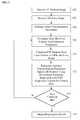
- FIG. 3illustrates a method for 2D/3D medical image registration using convolutional neural network (CNN) regression according to an embodiment of the present invention.
- the CNN regression-based 2D/3D registration method of FIG. 3can be referred to as Pose Estimation via Hierarchical Learning (PEHL).
- PEHLPose Estimation via Hierarchical Learning
- a 3D medical imageis received.
- the 3D medical imageis a 3D X-ray attenuation map.
- the 3D medical imagemay be a 3D X-ray attenuation map acquired using a computed tomography (CT) or cone-beam CT (CBCT) image acquisition device.
- CTcomputed tomography
- CBCTcone-beam CT
- the 3D medical imagemay be a 3D X-ray attenuation map generated by converting a 3D image, such as a 3D magnetic resonance imaging (MRI) image or a 3D computer aided design (CAD) image of a medical device or other object to a 3D X-ray attenuation map.
- MRImagnetic resonance imaging
- CADcomputer aided design
- the 3D medical imagemay be a pre-operative image acquired prior to a surgical procedure.
- the 3D medical imagemay be received directly from an image acquisition device, such as a CT or CBCT image acquisition device, or may be received by loading a previously generated or stored image from a memory or storage of a computer system.
- a 2D X-ray imageis received.
- the 2D X-ray imagemay be a frame in a sequence of X-ray images.
- the 2D X-ray imagemay be an intra-operative X-ray image received in a sequence of X-ray images acquired during a surgical procedure to guide the surgical procedure.
- the X-ray imagemay be received directly from an X-ray image acquisition device or may be received by loading a previously acquired X-ray image from a memory or storage of a computer system.
- the X-ray imageis received from the X-ray image acquisition device in real-time as it is acquired.
- initial transformation parametersare acquired.
- the initial transformation parametersare estimated by generating an initial DRR from the 3D medical image based on the X-ray image.
- the initial DRR having the initial transformation parameterscan be estimated using well-known techniques for generating a DRR to approximate a 2D X-ray image. For example, a well-understood template matching method can be used to estimate the initial transformation parameters and generate the initial DRR.
- a parameter space zoneis determined based on the current transformation parameters.
- the parameter space zoneis determined based on the current out-of-plane rotation transformation parameters.
- the parameter space zoneis determined based on the initial out-of-plane rotation transformation parameters.
- the parameter space zoneis determined by the most recently updated out-of-plane rotation transformation parameters.
- the method of FIG. 3utilizes regressors that are trained to recover the mapping from a feature X ( t ,I t + ⁇ t ) to the transformation parameter residuals ⁇ t . Since the feature naturally depends on t , the target mapping could vary significantly as t changes, which makes it highly complex and difficult to be accurately recovered. Ideally, it would be beneficial to extract a feature that is sensitive to the parameter residuals ⁇ t , and is insensitive to the transformations parameters t. Such a feature is referred to as a pose-index feature, and the property can be expressed as: X t 1 I t 1 + ⁇ t ⁇ X t 2 I t 2 + ⁇ t ⁇ t 1 t 2 .
- the method of FIG. 3uses regions of interest (ROIs) to make X ( t ,I t + ⁇ t ) invariant to the in-plane and scaling parameters, (t x , t y , t z , t ⁇ ).
- ROIsregions of interest
- the parameter space spanned by t ⁇ and t ⁇is partitioned into a plurality zones.
- the parameter space spanned by t ⁇ and t ⁇is partitioned into a plurality of zones by partitioning the parameter space into a grid of a specified size, such that each square in the grid covers a particular degrees area, which is set as a zone.
- the parameter space spanned by t ⁇ and t ⁇is partitioned into an 18 x 18 grid (determined empirically by the present inventors). Each square in the grid covers a 20 x 20 degrees area, and is set as a separate zone.
- the local image residual (LIR) introduced hereinis approximately pose-indexed , i.e.,: X k t 1 I t 1 + ⁇ t ⁇ X k t 2 I t 2 + ⁇ t ⁇ t 1 t 2 ⁇ ⁇ k , where X k ( ⁇ , ⁇ ) denotes the LIR feature extractor for the k -th zone, and ⁇ k denotes the area covered by the k -th zone.
- the regressorsare trained separately for each zone to recover the simplified mapping that is insensitive to t .
- LIR featuresare extracted from local patches of the DRR image and the X-ray image.
- the features for regressionare selected separately for each zone.
- the feature extraction method for one zoneis described herein, and the same method is applied for each zone.
- the LIR featureis calculated as the difference between the DRR rendered using the current transformation parameters t, denoted as It, and the X-ray image I t + ⁇ t in local patches.
- a number of 3D pointsare extracted from the 3D medical image.
- the 3D pointscorrespond to 2D edges and represent the 3D model of the target object.
- a square local ROIis uniquely determined in the 2D imaging plane, which can be described by a triplet, ( q , w, ⁇ ) , denoting the ROI's center, width, and orientation, respectively.
- the center qis the 2D projection of p using transformation parameters t.
- the width ww 0 • D / t z , where w 0 is the size of the ROI (e.g., in mm) and D is the distance between the X-ray source and detector.
- the orientation ⁇t ⁇ , so that it is always aligned with the target object.
- H p t ⁇is defined that extracts the image patch in the ROI determined by p and t, and re-samples the image patch to a fixed size (e.g., 52 x 52 in an exemplary implementation).
- P⁇ p 1 , ..., p N ⁇
- H p t I tapproximately invariant to t. Since the difference between H p t I t and H p t I t + ⁇ t is merely an additional 2D transformation caused by ⁇ t , H p t I t + ⁇ t is also approximately invariant to t .
- FIG. 4illustrates a workflow for calculating local image residual (LIR) features according to an embodiment of the present invention.
- FIG. 4illustrates LIR feature extraction as demonstrated on X-ray Echo Fusion data.
- image 402is an X-ray image ( I t + ⁇ t )
- image 404is a DRR ( I t ) rendered from a 3D model of a target object.
- image patches 406 H p t I t + ⁇ t and 408 H p t I tcorresponding to local ROIs determined from each 3D point p i and the transformation parameters t are extracted from the X-ray image 402 and the DRR 404, respectively.
- Each of the image patches 406 extracted from the X-ray image 402is subtracted from the corresponding one of the image patches 408 extracted from the DRR 404 to calculate the set of FIR features 410 ( X ( t , ⁇ t , P )).
- the 3D points used for calculating the FIR featuresare extracted separately for each zone.
- the 3D points of the 3D medical imagecan be calculated once for each zone prior to the surgical procedure and stored in a memory or storage of a computer system (e.g., in a database).
- the locations of the 3D points for the current zonecan then be retrieved and used to calculate the FIR features.
- the 3D pointsare extracted separately for each zone as follows. First, 3D points that correspond to edges are extracted as candidates.
- the candidatesare extracted by thresholding pixels with high gradient magnitudes in a synthetic X-ray image (i.e., generated using DRR) with t ⁇ and t ⁇ at the center of the zone, and then back-projecting them to the corresponding 3D structures.
- the intensity of the n-th pixel of H p i t j I t j ⁇ H p i t j I t j + ⁇ t kis denoted as h n,i,j,k .
- the candidate listis filtered by selecting the candidate with the largest ratio: F i / E i in the list, and then removing candidates with ROIs that have more than a certain percentage (e.g., 25%) overlapping area. This process can be repeated until the list is empty.
- updated transformation parametersare determined based on the LIR features using hierarchical parameter regression with CNN regressors trained for the current zone.
- the transformation parametersinstead of regressing the six transformation parameters together, which makes the mapping to be regressed extremely complex as multiple confounding factors are involved, the transformation parameters are divided into multiple groups, which are regressed hierarchically.
- the transformation parametersare divided into the following three groups and regressed hierarchically:
- the transformation parameters in Group 1are the easiest to be estimated, because they cause simple while dominant 2D transformations of the object in the projection image that are less affected by the variations of the parameters in the other two groups.
- the parameter in Group 3is the most difficult to be estimated, because it only causes subtle scaling of the object in the projection image.
- the difficulty in estimating parameters in Group 2falls in between. Accordingly, the three groups of transformation parameters are regressed sequentially from the easiest group (Group 1) to the most difficult group (Group 3). After a group of parameters are regressed, the LIR feature X ( t ,I t + ⁇ t ) is re-calculated using the already estimated updated translation parameters in the regression of the next group.
- mapping to be regressed for each groupis simplified by limiting the dimension and removing the compounding factors comping from those parameters in previous groups.
- the regression for each groupis performed by respective regressors trained for each group for the current zone. That is, for each zone, separate regressors are hierarchically trained for each group of transformation parameters.
- FIG. 5illustrates an algorithm for performing pose estimation via hierarchical regression (PHEL) according to an embodiment of the present invention.
- the algorithm of FIG. 5shows how steps of the method of FIG. 3 are implemented in an advantageous embodiment.
- the algorithm 500inputs and initial transformation parameters t, the X-ray image I , and a number of iterations k to be performed.
- the set of 3D points P for the zone covering ( t ⁇ , t ⁇ )is retrieved.
- the set of trained regressors f ( ⁇ ) for the zone covering ( t ⁇ , t ⁇ )is retrieved.
- the set of trained regressors f ( ⁇ ), for the current zoneincludes regressors trained for each group of transformation parameters for that zone.
- the LIR features X ( t , ⁇ t , P )are calculated using Equation (9).
- Steps 508 - 516provide details regarding the implementation of step 312 of FIG. 3 .
- the in-plane transformation parameters t x , t y , and t ⁇are updated using a first trained regressor f ⁇ x,y, ⁇ ⁇ for the current zone.
- the first trained regressor f x,y, ⁇calculates values for ⁇ t x , ⁇ t y , and ⁇ t ⁇ based on the LIR features X, and these values are added to the previous values for the in-plane transformation parameters t x , t y , and t ⁇ .
- the LIR features X ( t , ⁇ t , P )are re-calculated using Equation (9) with the updated values for the in-plane transformation parameters t x , t y , and t ⁇ .
- the out-of-plane rotation transformation parameters t ⁇ and t ⁇are updated using a second trained regressor f ⁇ ⁇ , ⁇ ⁇ for the current zone.
- the second trained regressor f ⁇ ⁇ , ⁇ ⁇calculates values for ⁇ t ⁇ and ⁇ t ⁇ based on the re-calculated LIR features X, and these values are added to the previous values for the out-of-plane rotation transformation parameters t ⁇ and t ⁇ .
- the LIR features X ( t , ⁇ t , P )are re-calculated using Equation (9) with the updated values for the in-plane transformation parameters t x , t y , t ⁇ and the updated values for the out-of-plane rotation transformation parameters t ⁇ , t ⁇
- the out-of-plane translation transformation parameter t zis updated using a third trained regressor f z for the current zone.
- the third trained regressor f zcalculates a value for ⁇ t z based on the re-calculated LIR features X, and this value is added to the previous value for the out-of-plane translation transformation parameter t z .
- Steps 502-516are repeated for k iterations, and the transformation parameters resulting from the current iterations is used as the starting position for the next iteration.
- the algorithmoutputs the final transformation parameters t , which provides the transformation that registers the 3D medical image to the coordinate system of the 2D X-ray image.
- the CNN regression modelshould be flexible enough to capture the complex mapping from X ( t , ⁇ t ) to ⁇ t x ; and (2) the CNN should be light-weighted enough to be forwarded in real-time and stored in Random Access Memory (RAM).
- RAMRandom Access Memory
- Managing the memory footprintis important because regressors trained for all zones (324 in total) should be loaded to RAM for optimal speed.
- the following CNN regression modelis employed to address these challenges.
- FIG. 6illustrates the architecture of a CNN regression model 600 trained for each group of transformation parameters in each zone according to an embodiment of the present invention.
- the input of the CNN regression model 600includes N input channels 602, corresponding to N LIR features.
- the CNN regression modelincludes N CNNs 604, and a respective one of the CNNs 604 is applied to each one of the input channels 602 for feature extraction.
- FIG. 7illustrates a structure of the CNN applied to each input channel according to an embodiment of the present invention.
- the CNN 700 of FIG. 7shows the structure for each of the N CNNs 604 of FIG. 6 . As shown in FIG.
- the CNN 700includes five layers, including two 5 x 5 convolutional layers (C1) 702 and (C2) 706, each followed by a 2 x 2 max pooling layer (P1) 704 and (P2) 708 with stride 2, and a fully connected layer (F1) 710 with 100 Rectified Linear Unit (ReLU) activation neurons.
- C1 702 and C2convolutional layers
- P1 704 and P22 x 2 max pooling layer
- F1 710with 100 Rectified Linear Unit (ReLU) activation neurons.
- the feature vectors extracted by the CNNs 604 from all of the input channels 602are then concatenated (606) and connected to another fully connected layer (F2) 608 with 250 ReLU activation neurons.
- the output layer (F3) 610is fully connected to F2 608, with each output node corresponding to one translation parameter in the group.
- the CNN regression model trained for group 1 for each zonehas three output nodes
- the CNN regression model trained for group 2 for each zonehas two output nodes
- the CNN regression model trained for group 3 for each zonehas one output node. Since the N input channels 602 have the same nature, i.e., they are LIR features at different locations, the weights in the N CNNs 604 are shared to reduce the memory footprint by N times.
- the present inventorsempirically selected the size of the ROI, which led to N ⁇ 18.
- N ⁇ 18the number of parameters in the group.
- the weightsare stored as 32-bit float, around 2.5 MB is required for each group in each zone.
- the CNN regression modelscan be trained exclusively on synthetic X-ray images, because they provide reliable ground truth labels with little need for laborious manual annotation, and the amount of real X-ray images may be limited.
- 25,000 pairs of t and ⁇ tare generated.
- the parameters tfollow a uniform distribution with t ⁇ and t ⁇ constrained in the zone.
- the parameter errors ⁇ talso follow a uniform distribution, while three different ranges are used for the three groups, as shown in Table 1, below.
- the distribution ranges of ⁇ t for Group 1are the target capture range that the regressors are designed for.
- Table 1Groug 1 Group 2 Group 3 ⁇ t x ⁇ u (-1.5,1.5) ⁇ t x ⁇ u (-0.2,0.2) ⁇ t x ⁇ u (-0.15,0.15) ⁇ t y ⁇ u (-1.5,1.5) ⁇ t y ⁇ u (-0.2,0.2), ⁇ t y ⁇ u (-0.15,0.15) ⁇ t z ⁇ u (-15,15) ⁇ t z ⁇ u (-15,15) ⁇ t z ⁇ u (-15,15) ⁇ t ⁇ ⁇ u (-3,3) ⁇ t ⁇ ⁇ u (-0.5,0.5) ⁇ t ⁇ ⁇ u (-0.5,0.5) ⁇ t ⁇ ⁇ u (-0.5,0.5) ⁇ t ⁇ ⁇ u (-15,15) ⁇ t ⁇ ⁇ u (-15,15) ⁇ t ⁇ ⁇ u (-0.75,0.75) ⁇ t ⁇ ⁇ u (-15, 15) ⁇ t ⁇ ⁇ u (-15,15
- W i ⁇ D i , W i + 1 :W i + V i + 1 , where i is the iteration index, V is the momentum variable, K i is the learning rate at the i -th iteration, and ⁇ ⁇ ⁇ ⁇ W
- the derivative ⁇ ⁇ ⁇ Wis calculated using back-propagation. For weights share in multiple paths, their derivatives in all paths are back-propagated separately and summed up for the weight update.
- the weightscan be initialized using the Xavier method and mini-batch SGD can be performed for a number of iterations (e.g., 12,500 iterations (32 epochs)).
- the stop conditionmay be a predetermined number of iterations, as shown in the algorithm 500 of FIG. 5 .
- the stop conditioncan be when the transformation parameters converge such that changes to the values of the transformation parameters in the most recent update are less than a predetermined threshold. If the stop condition is not met, the method returns to step 308, and steps 308-314 are repeated, starting with the current transformation parameters. When the stop condition is met, the method proceeds to step 316.
- the registration resultsare output.
- the final transformation parametersare output, and the transformation parameters provide a transformation that registers the 3D medical image to the coordinate system of the X-ray image.
- Information from the 3D medical imagecan then be projected or overlaid onto the X-ray image.
- a DDRcan be generated using the final transformation parameters and the DDR can be overlaid on the X-ray image to provide locations of organs or other anatomical structures that are more visible or defined in the 3D medical image than in the X-ray image.
- the resulting fused imagecan be displayed on a display device in real-time during the surgical procedure.
- the method of FIG. 3can be repeated in real-time for each X-ray image in a sequence of X-ray images.
- the methodreturns to step 304 for each X-ray image that is acquired, and in step 306, after the registration method is performed for a first X-ray image, the final transformation parameters determined for each X-ray image can be used as the initial transformation parameters for each subsequent X-ray image.
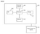
- Computer 802contains a processor 804, which controls the overall operation of the computer 802 by executing computer program instructions which define such operation.
- the computer program instructionsmay be stored in a storage device 812 (e.g., magnetic disk) and loaded into memory 810 when execution of the computer program instructions is desired.
- a storage device 812e.g., magnetic disk
- FIGS. 3 and 5the steps of the methods of FIGS. 3 and 5 may be defined by the computer program instructions stored in the memory 810 and/or storage 812 and controlled by the processor 804 executing the computer program instructions.
- An image acquisition device 820such as X-ray image acquisition device, CT image acquisition device, etc., can be connected to the computer 802 to input image data to the computer 802. It is possible to implement the image acquisition device 820 and the computer 802 as one device. It is also possible that the image acquisition device 820 and the computer 802 communicate wirelessly through a network. In a possible embodiment, the computer 802 can be located remotely with respect to the image acquisition device 820 and the method steps described herein can be performed as part of a server or cloud based service. In this case, the method steps may be performed on a single computer or distributed between multiple networked computers. The computer 802 also includes one or more network interfaces 806 for communicating with other devices via a network.
- the computer 802also includes other input/output devices 808 that enable user interaction with the computer 802 (e.g., display, keyboard, mouse, speakers, buttons, etc.). Such input/output devices 808 may be used in conjunction with a set of computer programs as an annotation tool to annotate volumes received from the image acquisition device 820.
- input/output devices 808may be used in conjunction with a set of computer programs as an annotation tool to annotate volumes received from the image acquisition device 820.
- FIG. 8is a high level representation of some of the components of such a computer for illustrative purposes.
Landscapes
- Engineering & Computer Science (AREA)
- Physics & Mathematics (AREA)
- Theoretical Computer Science (AREA)
- General Physics & Mathematics (AREA)
- Data Mining & Analysis (AREA)
- Life Sciences & Earth Sciences (AREA)
- General Health & Medical Sciences (AREA)
- Health & Medical Sciences (AREA)
- General Engineering & Computer Science (AREA)
- Evolutionary Computation (AREA)
- Artificial Intelligence (AREA)
- Mathematical Physics (AREA)
- Computing Systems (AREA)
- Biomedical Technology (AREA)
- Biophysics (AREA)
- Computational Linguistics (AREA)
- Software Systems (AREA)
- Molecular Biology (AREA)
- Computer Vision & Pattern Recognition (AREA)
- Nuclear Medicine, Radiotherapy & Molecular Imaging (AREA)
- Radiology & Medical Imaging (AREA)
- Medical Informatics (AREA)
- Quality & Reliability (AREA)
- Probability & Statistics with Applications (AREA)
- Bioinformatics & Cheminformatics (AREA)
- Bioinformatics & Computational Biology (AREA)
- Evolutionary Biology (AREA)
- Image Analysis (AREA)
Abstract
Description
- The present invention relates to two dimensional (2D) to three dimensional (3D) medical image registration, and more particularly, to deep learning based 2D/3D medical image registration.
- Two dimensional (2D) to three dimensional (3D) image registration is an important technology in medical imaging and image-guided interventions. 2D/3D image registration can be used to bring pre-operative 3D medical image data and intra-operative 2D medical image data into the same coordinate system to facilitate accurate diagnosis and/or provided advanced image guidance. For example, the pre-operative 3D medical image data generally includes computed tomography (CT), cone-beam CT (CBCT), magnetic resonance imaging (MRI), and/or computer aided design (CAD) models of medical devices, while the intra-operative 2D medical image data is typically X-ray images.
- 2D/3D image registration is typically achieved using intensity-based methods. In such intensity-based 2D/3D image registration methods, in order to register a 3D X-ray attenuation map provided by CT or CBCT (or converted from another imaging modality), a simulated X-ray image, referred to as a digitally reconstructed radiograph (DRR), is derived from the 3D attenuation map by simulating the attenuation of virtual X-rays. An optimizer is then employed to maximize an intensity-based similarity measure between the DRR and X-ray images. Intensity-based methods are able to achieve high registration accuracy, but suffer drawbacks including long computation time and small capture range. Because intensity-based methods involve a large number of evaluations of the similarity measure, each requiring heavy computation in rendering the DRR, such methods typically result in running times greater than one second, and therefore are not suitable for real-time applications. In addition, because the similarity measures to be optimized in intensity-based methods are often highly non-convex, the optimizer has a high chance of getting trapped into a local maxima, which leads to such methods having a small capture range in which high registration accuracy can be achieved.
- The present invention provides a method and system for 2D/3D medical image registration deep learning-based regression. Embodiments of the present invention achieve real-
time 2D/3D medical image registration with a large capture range and high accuracy. Embodiments of the present invention train convolutional neural network (CNN) regressors to determine a mapping from a 2D medical image and digitally reconstructed radiograph (DRR) generated from a 3D medical image to the difference of their underlying transformation parameters. Embodiments of the present invention utilize a local image residual (LIR) feature to simplify the underlying mapping to be captured by the CNN regressors Embodiments of the present invention utilize parameter space partitioning (PSP) to partition the transformation parameter space into zones and train CNN regressors in each zone separately. Embodiments of the present invention utilize hierarchical parameter regression (HPR) to decompose the transformation parameters and regress them in a hierarchical manner. - In one embodiment of the present invention, a parameter space zone is determined based on transformation parameters corresponding to a digitally reconstructed radiograph (DRR) generated from the 3D medical image. Local image residual (LIR) features are calculated from local patches of the DRR and the X-ray image based on a set of 3D points in the 3D medical image extracted for the determined parameter space zone. Updated transformation parameters are calculated based on the LIR features using a hierarchical series of regressors trained for the determined parameter space zone. The hierarchical series of regressors includes a plurality of regressors each of which calculates updates for a respective subset of the transformation parameters.
- These and other advantages of the invention will be apparent to those of ordinary skill in the art by reference to the following detailed description and the accompanying drawings.
FIG. 1 illustrates effects of the six transformation parameters according to an embodiment of the present invention;FIG. 2 illustrates an example of X-ray perspective geometry;FIG. 3 illustrates a method for 2D/3D medical image registration using convolutional neural network (CNN) regression according to an embodiment of the present invention;FIG. 4 illustrates a workflow for calculating local image residual (LIR) features according to an embodiment of the present invention;FIG. 5 illustrates an algorithm for performing pose estimation via hierarchical regression (PHEL) according to an embodiment of the present invention;FIG. 6 illustrates the architecture of a CNN regression model trained for each group of transformation parameters in each zone according to an embodiment of the present invention;FIG. 7 illustrates a structure of the CNN applied to each input channel according to an embodiment of the present invention; andFIG. 8 is a high-level block diagram of a computer capable of implementing the present invention.- The present invention relates to a method and system for 2D/3D medical image registration using deep learning-based regression. Embodiments of the present invention are described herein to give a visual understanding of the 2D/3D medical image registration method. A digital image is often composed of digital representations of one or more objects (or shapes). The digital representation of an object is often described herein in terms of identifying and manipulating the objects. Such manipulations are virtual manipulations accomplished in the memory or other circuitry / hardware of a computer system. Accordingly, is to be understood that embodiments of the present invention may be performed within a computer system using data stored within the computer system.
- Embodiments of the present invention are described herein as registering a 3D X-ray attenuation map provided by a CT or CBCT with a 2D X-ray image in real-time. Depending on the application, other 3D modalities, such as MRI or a CAD model, can be converted to a 3D X-ray attenuation map before performing the 2D/3D registration.
- Assuming that the X-ray imaging system corrects the beam divergence and the X-ray sensor has a logarithm static response, X-ray image generation can be described by the following model:


- A rigid-
body 3D transformationT can be parameterized by a vectort with six components. According to an advantageous embodiment, the transformation is parameterized by three in-plane transformation parameters and three out-of-plane transformation parameters.FIG. 1 illustrates effects of the six transformation parameters according to an embodiment of the present invention. As shown in,FIG. 1 , the in-plane transformation parameters include two in-plane translation parameters,t x 102 andt rotation parametert θ 108. The effects of the in-plant transformation parameters translation parameter t z 106, and two out-of-planerotation parameterst α 110 andt β 112. The effects of the out-of-plane translation 106 androtations - Mathematical definitions of the in-plane and out-of-plane parameters are given as follows.
FIG. 2 illustrates an example of X-ray perspective geometry. As shown inFIG. 2 , X-ray beams are transmitted from the X-ray source 202 through anobject 204, resulting in an image projected onto theX-ray imaging plane 206. The horizontal axis, vertical axis, and normal direction of theX-ray imaging plane 206 are denoted asex, ey, andez, respectively. The center of theX-ray imaging plane 206 is denoted ascp. On the object to be registered 204, two orthogonal axes are defined, denoted aseα andeb, and a reference point (preferably at the geometric center) is selected and denoted asco. The translation parameters,tx, ty, andtz, are defined as:


- The in-plane rotation parametertθ, also referred to as "yaw", is defined as the angle betweeney and the projection ofeα on the imaging plane:

- The out-of-plane rotation parametertα, also referred to as "pitch", is defined as the angle betweeneα and its projection on the imaging plane:

- The out-of-plane rotation parametertβ, also referred to as "roll", is defined as the angle betweeneb and the projection ofez on the plane perpendicular toeα:

- Based on Equation (3), we denote the X-ray image with transformation parameterst asIt, where the variables L andj are omitted for simplicity because they are non-varying for a given 2D/3D registration task. The inputs for the 2D/3D registration are: (1) a 3D object described by its X-ray attenuation mapJ; (2) an X-ray imageIt
gt , wheretgt denotes the unknown ground truth transformation parameters; and (3) initial transformation parameterstini. The 2D/3D registration problem can be formulated as a regression problem, where a set of machine-learning based regressorsf(·) are trained based on training data to learn a mapping from a featureX (tini,Itgt ) extracted from the inputs to parameter residuals,tgt -tini, as long as the initial transformation parameterstini are within a capture range∈ of the ground truth transformation parameterstgt:
- An estimation oftgt is then obtained by applying the regressors and incorporating the estimated parameter residuals intotini:

- It is worth noting that the range∈ in Equation (4) is equivalent to the range of optimization-based registration methods. Based on Equation (4), the problem formulation can be expressed as designing a feature extractorX(·) and training regressorsf(·), such that:

- Embodiments of the present invention described below discuss in detail how the feature (X(t,It+δt)) is calculated and how the regressorsf(·) are designed, trained, and applied, to achieve accurate, real-
time 2D/3D medical image registration. FIG. 3 illustrates a method for 2D/3D medical image registration using convolutional neural network (CNN) regression according to an embodiment of the present invention. The CNN regression-based 2D/3D registration method ofFIG. 3 can be referred to as Pose Estimation via Hierarchical Learning (PEHL). Referring toFIG. 3 , atstep 302, a 3D medical image is received. In an advantageous embodiment, the 3D medical image is a 3D X-ray attenuation map. For example, the 3D medical image may be a 3D X-ray attenuation map acquired using a computed tomography (CT) or cone-beam CT (CBCT) image acquisition device. Alternatively, the 3D medical image may be a 3D X-ray attenuation map generated by converting a 3D image, such as a 3D magnetic resonance imaging (MRI) image or a 3D computer aided design (CAD) image of a medical device or other object to a 3D X-ray attenuation map. Techniques for converting such images to a 3D X-ray attenuation map are well known. In an advantageous embodiment, the 3D medical image may be a pre-operative image acquired prior to a surgical procedure. The 3D medical image may be received directly from an image acquisition device, such as a CT or CBCT image acquisition device, or may be received by loading a previously generated or stored image from a memory or storage of a computer system.- At
step 304, a 2D X-ray image is received. The 2D X-ray image may be a frame in a sequence of X-ray images. In an advantageous embodiment, the 2D X-ray image may be an intra-operative X-ray image received in a sequence of X-ray images acquired during a surgical procedure to guide the surgical procedure. The X-ray image may be received directly from an X-ray image acquisition device or may be received by loading a previously acquired X-ray image from a memory or storage of a computer system. In an advantageous embodiment, the X-ray image is received from the X-ray image acquisition device in real-time as it is acquired. - At
step 306, initial transformation parameters are acquired. The initial transformation parameters are estimated by generating an initial DRR from the 3D medical image based on the X-ray image. The initial DRR having the initial transformation parameters can be estimated using well-known techniques for generating a DRR to approximate a 2D X-ray image. For example, a well-understood template matching method can be used to estimate the initial transformation parameters and generate the initial DRR. - At
step 308, a parameter space zone is determined based on the current transformation parameters. In an advantageous implementation, the parameter space zone is determined based on the current out-of-plane rotation transformation parameters. In the first iteration ofstep 308, the parameter space zone is determined based on the initial out-of-plane rotation transformation parameters. In each subsequent iteration ofstep 308, the parameter space zone is determined by the most recently updated out-of-plane rotation transformation parameters. - The method of
FIG. 3 utilizes regressors that are trained to recover the mapping from a featureX(t,It+δt) to the transformation parameter residualsδt. Since the feature naturally depends ont, the target mapping could vary significantly as t changes, which makes it highly complex and difficult to be accurately recovered. Ideally, it would be beneficial to extract a feature that is sensitive to the parameter residualsδt, and is insensitive to the transformations parameterst. Such a feature is referred to as a pose-index feature, and the property can be expressed as:
step 310, the method ofFIG. 3 uses regions of interest (ROIs) to makeX(t,It+δt) invariant to the in-plane and scaling parameters,(tx, ty, tz, tθ). However, we are unable to makeX(t,It+δt) invariant totα andtβ because these parameters cause complex appearance changes in the projection image. According to an embodiment of the present invention, to solve this problem, the parameter space spanned bytα andtβ is partitioned into a plurality zones. The parameter space spanned bytα andtβ is partitioned into a plurality of zones by partitioning the parameter space into a grid of a specified size, such that each square in the grid covers a particular degrees area, which is set as a zone. In an advantageous implementation, the parameter space spanned bytα andtβ is partitioned into an 18 x 18 grid (determined empirically by the present inventors). Each square in the grid covers a 20 x 20 degrees area, and is set as a separate zone. As will be discussed in greater detail in connection withstep 310, for the out-of-plane rotation transformation parameterstα andtβ within each zone, the local image residual (LIR) introduced herein is approximately pose-indexed , i.e.,:
- Returning to
FIG. 3 , atstep 310, LIR features are extracted from local patches of the DRR image and the X-ray image. The features for regression are selected separately for each zone. The feature extraction method for one zone is described herein, and the same method is applied for each zone. The LIR feature is calculated as the difference between the DRR rendered using the current transformation parameterst, denoted asIt, and the X-ray imageIt+δt in local patches. To determine the locations, sizes, orientations of the local patches, a number of 3D points are extracted from the 3D medical image. The 3D points correspond to 2D edges and represent the 3D model of the target object. Given a 3D pointp and transformation parameterst, a square local ROI is uniquely determined in the 2D imaging plane, which can be described by a triplet, (q, w, φ), denoting the ROI's center, width, and orientation, respectively. The centerq is the 2D projection ofp using transformation parameterst. The width w = w0• D/tz, where w0 is the size of the ROI (e.g., in mm) andD is the distance between the X-ray source and detector. The orientationφ =tθ, so that it is always aligned with the target object. An operator
N 3D points, P = {p1,...,pN}, the LIR feature is then calculated as:
- In the local areaof It, the effect of varyingtα andtβ within a zone is approximately a 2D translation. Therefore, by extracting the local patches from ROIs selected based ont, the effects of all six translation parameters int are compensated, making


FIG. 4 illustrates a workflow for calculating local image residual (LIR) features according to an embodiment of the present invention.FIG. 4 illustrates LIR feature extraction as demonstrated on X-ray Echo Fusion data. As shown inFIG. 4 ,image 402 is an X-ray image (It+δt) andimage 404 is a DRR (It) rendered from a 3D model of a target object. Given aset 3D pointsP, image patches 406

X-ray image 402 and theDRR 404, respectively. Each of theimage patches 406 extracted from theX-ray image 402 is subtracted from the corresponding one of theimage patches 408 extracted from theDRR 404 to calculate the set of FIR features 410 (X(t, δt,P)).- The 3D points used for calculating the FIR features are extracted separately for each zone. In an exemplary implementation, the 3D points of the 3D medical image can be calculated once for each zone prior to the surgical procedure and stored in a memory or storage of a computer system (e.g., in a database). When performing registration of the 3D medical image with X-ray images acquired in real-time, the locations of the 3D points for the current zone can then be retrieved and used to calculate the FIR features. The 3D points are extracted separately for each zone as follows. First, 3D points that correspond to edges are extracted as candidates. Specifically, the candidates are extracted by thresholding pixels with high gradient magnitudes in a synthetic X-ray image (i.e., generated using DRR) withtα andtβ at the center of the zone, and then back-projecting them to the corresponding 3D structures. The formation model of gradients in X-ray images can be expressed as:


- The condition in Equation (12) ensures that the 3D structure aroundL(p,r) "essentially generates" the 2D gradientg(p) because the contribution ofη(·) within a small neighborhood (e.g., σ = 2 mm) ofL(p,r0) leads to the majority (i.e., ≥ 90%) of the magnitude ofg(p). In other words, we find the dominant 3D structure corresponding to the gradient in the X-ray image.
- Once the candidates are extracted, the candidates are filtered so that only ones leading to LIR features satisfying Equation (7) and also not significantly overlapped are kept. This is achieved by randomly generating


- Returning to
FIG. 3 , atstep 312, updated transformation parameters are determined based on the LIR features using hierarchical parameter regression with CNN regressors trained for the current zone. According to an advantageous embodiment of the present invention, instead of regressing the six transformation parameters together, which makes the mapping to be regressed extremely complex as multiple confounding factors are involved, the transformation parameters are divided into multiple groups, which are regressed hierarchically. According to an advantageous implementation, the transformation parameters are divided into the following three groups and regressed hierarchically: - Group 1: In-plane transformation parameters:δtx, δty, andδtθ;
- Group 2: Out-of-plane rotation transformation parameters:δtα andδtβ;
- Group 3: Out-of-plane translation transformation parameter:δtz.
- Among the three groups, the transformation parameters in
Group 1 are the easiest to be estimated, because they cause simple while dominant 2D transformations of the object in the projection image that are less affected by the variations of the parameters in the other two groups. The parameter inGroup 3 is the most difficult to be estimated, because it only causes subtle scaling of the object in the projection image. The difficulty in estimating parameters in Group 2 falls in between. Accordingly, the three groups of transformation parameters are regressed sequentially from the easiest group (Group 1) to the most difficult group (Group 3). After a group of parameters are regressed, the LIR featureX(t,It+δt) is re-calculated using the already estimated updated translation parameters in the regression of the next group. This way, the mapping to be regressed for each group is simplified by limiting the dimension and removing the compounding factors comping from those parameters in previous groups. The regression for each group is performed by respective regressors trained for each group for the current zone. That is, for each zone, separate regressors are hierarchically trained for each group of transformation parameters. FIG. 5 illustrates an algorithm for performing pose estimation via hierarchical regression (PHEL) according to an embodiment of the present invention. The algorithm ofFIG. 5 shows how steps of the method ofFIG. 3 are implemented in an advantageous embodiment. As shown inFIG. 5 , thealgorithm 500 inputs and initial transformation parameterst, the X-ray imageI, and a number of iterationsk to be performed. Atstep 502, the set of 3D pointsP for the zone covering (tα, tβ) is retrieved. Atstep 504, the set of trained regressorsf(·) for the zone covering (tα, tβ) is retrieved. The set of trained regressorsf(·), for the current zone includes regressors trained for each group of transformation parameters for that zone. Atstep 506, the LIR featuresX(t,δt,P) are calculated using Equation (9).- Steps 508 - 516 provide details regarding the implementation of
step 312 ofFIG. 3 . Atstep 508, the in-plane transformation parameterstx, ty, andtθ are updated using a first trained regressorf{x,y,θ} for the current zone. The first trained regressorfx,y,θ calculates values forδtx,δty, andδtθ based on the LIR featuresX, and these values are added to the previous values for the in-plane transformation parameterstx, ty, andtθ. Atstep 510, the LIR featuresX(t,δt,P) are re-calculated using Equation (9) with the updated values for the in-plane transformation parameterstx, ty, andtθ. Atstep 512, the out-of-plane rotation transformation parameterstα andtβ are updated using a second trained regressorf{α,β} for the current zone. The second trained regressorf{α,β} calculates values forδtα andδtβ based on the re-calculated LIR featuresX, and these values are added to the previous values for the out-of-plane rotation transformation parameterstα andtβ. Atstep 514, the LIR featuresX(t,δt,P) are re-calculated using Equation (9) with the updated values for the in-plane transformation parameterstx, ty, tθ and the updated values for the out-of-plane rotation transformation parameterstα, tβ Atstep 516, the out-of-plane translation transformation parametertz is updated using a third trained regressorfz for the current zone. The third trained regressorfz calculates a value forδtz based on the re-calculated LIR featuresX, and this value is added to the previous value for the out-of-plane translation transformation parametertz. - Steps 502-516 are repeated for k iterations, and the transformation parameters resulting from the current iterations is used as the starting position for the next iteration. The number of iterationsk can be determined empirically. In an exemplary implementation,k = 3 iterations can be used. At
step 518, the algorithm outputs the final transformation parameterst, which provides the transformation that registers the 3D medical image to the coordinate system of the 2D X-ray image. - In the hierarchical regression approach used in
step 312 ofFIG. 3 and the algorithm ofFIG. 5 , designing the CNN regression model are two-fold: (1) the CNN regression model should be flexible enough to capture the complex mapping fromX(t,δt) toδtx; and (2) the CNN should be light-weighted enough to be forwarded in real-time and stored in Random Access Memory (RAM). Managing the memory footprint is important because regressors trained for all zones (324 in total) should be loaded to RAM for optimal speed. In an advantageous embodiment, the following CNN regression model is employed to address these challenges. - Network Structure:
FIG. 6 illustrates the architecture of aCNN regression model 600 trained for each group of transformation parameters in each zone according to an embodiment of the present invention. According to Equation (9), the input of theCNN regression model 600 includesN input channels 602, corresponding toN LIR features. The CNN regression model includesN CNNs 604, and a respective one of theCNNs 604 is applied to each one of theinput channels 602 for feature extraction.FIG. 7 illustrates a structure of the CNN applied to each input channel according to an embodiment of the present invention. TheCNN 700 ofFIG. 7 shows the structure for each of theN CNNs 604 ofFIG. 6 . As shown inFIG. 7 , theCNN 700 includes five layers, including two 5 x 5 convolutional layers (C1) 702 and (C2) 706, each followed by a 2 x 2 max pooling layer (P1) 704 and (P2) 708 with stride 2, and a fully connected layer (F1) 710 with 100 Rectified Linear Unit (ReLU) activation neurons. Returning toFIG. 6 , the feature vectors extracted by theCNNs 604 from all of theinput channels 602 are then concatenated (606) and connected to another fully connected layer (F2) 608 with 250 ReLU activation neurons. The output layer (F3) 610 is fully connected toF2 608, with each output node corresponding to one translation parameter in the group. For example, the CNN regression model trained forgroup 1 for each zone has three output nodes, the CNN regression model trained for group 2 for each zone has two output nodes, and the CNN regression model trained forgroup 3 for each zone has one output node. Since theN input channels 602 have the same nature, i.e., they are LIR features at different locations, the weights in theN CNNs 604 are shared to reduce the memory footprint byN times. - In an exemplary implementation, the present inventors empirically selected the size of the ROI, which led toN ≈ 18. In this implementation, using the
CNN model 600 shown inFIG. 6 with weight sharing, there are in total 660,500 weights for each group in each zone, excluding the output layer, which only has 250 x Nt weights, whereNt is the number of parameters in the group. If the weights are stored as 32-bit float, around 2.5 MB is required for each group in each zone. Given 3 groups and 324 zones, there are in total 972 CNN regression models and pre-loading all of them into RAM requires 2.39 GB, which is manageable for modern computers. - Training: In an advantageous implementation, the CNN regression models can be trained exclusively on synthetic X-ray images, because they provide reliable ground truth labels with little need for laborious manual annotation, and the amount of real X-ray images may be limited. In an exemplary implementation, for each group in each zone, 25,000 pairs oft andδt are generated. The parameterst follow a uniform distribution withtα andtβ constrained in the zone. The parameter errorsδt also follow a uniform distribution, while three different ranges are used for the three groups, as shown in Table 1, below. The distribution ranges ofδt for
Group 1 are the target capture range that the regressors are designed for. The distribution ranges ofδtx, δty, andδtθ are reduced for Group 2, because they are close to zero after the regressors in the first group are applied. For the same reason, the distribution in the ranges ofδtα andδtβ are reduced forGroup 3. For each pair oft andδt, a synthetic X-ray imageIt+δt is generated and the LIR featuresX(t,It+δt) are calculated using Equation (9).Table 1 Groug 1Group 2 Group 3δtx ∼u(-1.5,1.5) δtx ∼u(-0.2,0.2) δtx ∼u (-0.15,0.15) δty ∼u(-1.5,1.5) δty ∼u(-0.2,0.2), δty∼u(-0.15,0.15) δtz ∼u(-15,15) δtz ∼u(-15,15) δtz ∼u(-15,15) δtθ ∼u(-3,3) δtθ ∼u(-0.5,0.5) δtθ ∼u(-0.5,0.5) δtα ∼u(-15,15) δtα ∼u(-15,15) δtα ∼u(-0.75,0.75) δtβ∼u(-15, 15) δtβ ∼u(-15,15) δtβ ∼u (-0.75,0.75) - The objective function to be minimized during the training is the Euclidean loss, defined as:


- Returning to
FIG. 3 , atstep 314, it is determined whether a stop condition is met. For example, the stop condition may be a predetermined number of iterations, as shown in thealgorithm 500 ofFIG. 5 . Alternatively, the stop condition can be when the transformation parameters converge such that changes to the values of the transformation parameters in the most recent update are less than a predetermined threshold. If the stop condition is not met, the method returns to step 308, and steps 308-314 are repeated, starting with the current transformation parameters. When the stop condition is met, the method proceeds to step 316. - At
step 316, the registration results are output. In particular, the final transformation parameters are output, and the transformation parameters provide a transformation that registers the 3D medical image to the coordinate system of the X-ray image. Information from the 3D medical image can then be projected or overlaid onto the X-ray image. For example, a DDR can be generated using the final transformation parameters and the DDR can be overlaid on the X-ray image to provide locations of organs or other anatomical structures that are more visible or defined in the 3D medical image than in the X-ray image. The resulting fused image can be displayed on a display device in real-time during the surgical procedure. - The method of
FIG. 3 can be repeated in real-time for each X-ray image in a sequence of X-ray images. In this case, the method returns to step 304 for each X-ray image that is acquired, and instep 306, after the registration method is performed for a first X-ray image, the final transformation parameters determined for each X-ray image can be used as the initial transformation parameters for each subsequent X-ray image. - The above-described methods for 2D/3D medical image registration may be implemented on a computer using well-known computer processors, memory units, storage devices, computer software, and other components. A high-level block diagram of such a computer is illustrated in
FIG. 8 .Computer 802 contains aprocessor 804, which controls the overall operation of thecomputer 802 by executing computer program instructions which define such operation. The computer program instructions may be stored in a storage device 812 (e.g., magnetic disk) and loaded intomemory 810 when execution of the computer program instructions is desired. Thus, the steps of the methods ofFIGS. 3 and5 may be defined by the computer program instructions stored in thememory 810 and/orstorage 812 and controlled by theprocessor 804 executing the computer program instructions. Animage acquisition device 820, such as X-ray image acquisition device, CT image acquisition device, etc., can be connected to thecomputer 802 to input image data to thecomputer 802. It is possible to implement theimage acquisition device 820 and thecomputer 802 as one device. It is also possible that theimage acquisition device 820 and thecomputer 802 communicate wirelessly through a network. In a possible embodiment, thecomputer 802 can be located remotely with respect to theimage acquisition device 820 and the method steps described herein can be performed as part of a server or cloud based service. In this case, the method steps may be performed on a single computer or distributed between multiple networked computers. Thecomputer 802 also includes one ormore network interfaces 806 for communicating with other devices via a network. Thecomputer 802 also includes other input/output devices 808 that enable user interaction with the computer 802 (e.g., display, keyboard, mouse, speakers, buttons, etc.). Such input/output devices 808 may be used in conjunction with a set of computer programs as an annotation tool to annotate volumes received from theimage acquisition device 820. One skilled in the art will recognize that an implementation of an actual computer could contain other components as well, and thatFIG. 8 is a high level representation of some of the components of such a computer for illustrative purposes. - The foregoing Detailed Description is to be understood as being in every respect illustrative and exemplary, but not restrictive, and the scope of the invention disclosed herein is not to be determined from the Detailed Description, but rather from the claims as interpreted according to the full breadth permitted by the patent laws. It is to be understood that the embodiments shown and described herein are only illustrative of the principles of the present invention and that various modifications may be implemented by those skilled in the art without departing from the scope and spirit of the invention. Those skilled in the art could implement various other feature combinations without departing from the scope and spirit of the invention.


Claims (19)
- A method for registering a 3D medical image with a 2D X-ray image, comprising:determining a parameter space zone based on transformation parameters corresponding to a digitally reconstructed radiograph (DRR) generated from the 3D medical image;calculating local image residual (LIR) features from local patches of the DRR and the X-ray image based on a set of 3D points in the 3D medical image extracted for the determined parameter space zone; andcalculating updated transformation parameters based on the LIR features using a hierarchical series of regressors trained for the determined parameter space zone, wherein the hierarchical series of regressors includes a plurality of regressors each of which calculates updates for a respective subset of the transformation parameters.
- The method of claim 1, wherein the transformation parameters include two in-plane translational transformation parameters, one out-of-plane translation transformation parameter, two out-of-plant rotation transformation parameters, and one out-of-plane translation transformation parameter, in particular wherein determining a parameter space zone based on transformation parameters corresponding to a digitally reconstructed radiograph (DRR) generated from the 3D medical image comprises:determining the parameter space zone based on the two out-of-plane rotation transformation parameters, in particular wherein a parameter space of the two out-of-plane rotation transformation parameters is partitioned into a predetermined number of parameter space zones, each covering a predetermined area of the parameter space of the two out-of-plane rotation transformation parameters.
- The method of claim 2, wherein calculating updated transformation parameters based on the LIR features using a hierarchical series of regressors trained for the determined parameter space zone comprises:calculating updates for the in-plane translational transformation parameters and the in-plane rotational transformation parameter based on the LIR features using a first convolutional neural network (CNN) regressor trained for the determined parameter space zone;re-calculating the LIR features based on the updated in-plane translational transformation parameters and in-plane rotational transformation parameter; calculating updates for the out-of-plane rotational transformation parameters based on the LIR features using a second CNN regressor trained for the determined parameter space zone;re-calculating the LIR features based on the updated out-of-plane rotational transformation parameters; and
calculating updates for the out-of-plane translational transformation parameter based on the LIR features using a third CNN regressor trained for the determined parameter space zone. - The method of claim 1, wherein the hierarchical series of regressors is a hierarchical series of trained convolutional neural network (CNN) regressors.
- The method of claim 1, wherein calculating local image residual (LIR) features from local patches of the DRR and the X-ray image based on a set of 3D points in the 3D medical image extracted for the determined parameter space zone comprises:for each 3D point in the set of 3D points, extracting corresponding local image patches in the DRR and the X-ray image based on a 2D region of interest determined for the 3D; andcalculating the LIR features by subtracting each local image patch extracted in the X-ray image from the corresponding local image patch extracted in the DRR.
- The method of claim 7, wherein the set of 3D points extracted for the determined parameter space zone includes 3D points corresponding to 2D edges in the DRR or further comprising:extracting the 3D points for the determined parameter space zone by:generating candidate 3D points in the 3D medical image for the parameter space zone by thresholding pixels in a 2D DRR centered in the parameter space zone with high gradient magnitudes and back-projecting the pixels with high gradient magnitudes to corresponding 3D structures in the 3D medical image; andfiltering the candidate 3D points to select candidate 3D points with LIR feature values that are invariant to the transformation parameters but sensitive to transformation parameter residuals and remove candidate 3D points with overlapping regions of interest.
- The method of claim 1, further comprising:repeating determining the parameter space zone, calculating the LIR features, and calculating the updated transformation parameters for a plurality of iterations or further comprising:repeating determining a parameter space zone, calculating LIR features, andcalculating updated transformation parameters for a second X-ray image, starting with the updated transformation parameters calculated to register the 3D medical image to the X-ray image as initial transformation parameters for registering the 3D medical image to the second X-ray image.
- An apparatus for registering a 3D medical image with a 2D X-ray image, comprising:means for determining a parameter space zone based on transformation parameters corresponding to a digitally reconstructed radiograph (DRR) generated from the 3D medical image;means for calculating local image residual (LIR) features from local patches of the DRR and the X-ray image based on a set of 3D points in the 3D medical image extracted for the determined parameter space zone; andmeans for calculating updated transformation parameters based on the LIR features using a hierarchical series of regressors trained for the determined parameter space zone, wherein the hierarchical series of regressors includes a plurality of regressors each of which calculates updates for a respective subset of the transformation parameters.
- The apparatus of claim 8, wherein the transformation parameters include two in-plane translational transformation parameters, one out-of-plane translation transformation parameter, two out-of-plant rotation transformation parameters, and one out-of-plane translation transformation parameter.
- The apparatus of claim 9, wherein the means for determining a parameter space zone based on transformation parameters corresponding to a digitally reconstructed radiograph (DRR) generated from the 3D medical image comprises:means for determining the parameter space zone based on the two out-of-plane rotation transformation parameters.
- The apparatus of claim 10, wherein a parameter space of the two out-of-plane rotation transformation parameters is partitioned into a predetermined number of parameter space zones, each covering a predetermined area of the parameter space of the two out-of-plane rotation transformation parameters.
- The apparatus of claim 9, wherein the means for calculating updated transformation parameters based on the LIR features using a hierarchical series of regressors trained for the determined parameter space zone comprises:means for calculating updates for the in-plane translational transformation parameters and the in-plane rotational transformation parameter based on the LIR features using a first convolutional neural network (CNN) regressor trained for the determined parameter space zone;means for re-calculating the LIR features based on the updated in-plane translational transformation parameters and in-plane rotational transformation parameter;means for calculating updates for the out-of-plane rotational transformation parameters based on the LIR features using a second CNN regressor trained for the determined parameter space zone;
means for re-calculating the LIR features based on the updated out-of-plane rotational transformation parameters; and
means for calculating updates for the out-of-plane translational transformation parameter based on the LIR features using a third CNN regressor trained for the determined parameter space zone. - The apparatus of claim 8, wherein the hierarchical series of regressors is a hierarchical series of trained convolutional neural network (CNN) regressors or wherein the means for calculating local image residual (LIR) features from local patches of the DRR and the X-ray image based on a set of 3D points in the 3D medical image extracted for the determined parameter space zone comprises:means for extracting, for each 3D point in the set of 3D points, corresponding local image patches in the DRR and the X-ray image based on a 2D region of interest determined for the 3D; andmeans for calculating the LIR features by subtracting each local image patch extracted in the X-ray image from the corresponding local image patch extracted in the DRR.
- A non-transitory computer readable medium storing computer program instructions for registering a 3D medical image with a 2D X-ray image, the computer program instructions when executed by a processor cause the processor to perform operations comprising:determining a parameter space zone based on transformation parameters corresponding to a digitally reconstructed radiograph (DRR) generated from the 3D medical image;calculating local image residual (LIR) features from local patches of the DRR and the X-ray image based on a set of 3D points in the 3D medical image extracted for the determined parameter space zone; andcalculating updated transformation parameters based on the LIR features using a hierarchical series of regressors trained for the determined parameter space zone, wherein the hierarchical series of regressors includes a plurality of regressors each of which calculates updates for a respective subset of the transformation parameters.
- The non-transitory computer readable medium of claim 14, wherein the transformation parameters include two in-plane translational transformation parameters, one out-of-plane translation transformation parameter, two out-of-plant rotation transformation parameters, and one out-of-plane translation transformation parameter.
- The non-transitory computer readable medium of claim 15, wherein determining a parameter space zone based on transformation parameters corresponding to a digitally reconstructed radiograph (DRR) generated from the 3D medical image comprises:determining the parameter space zone based on the two out-of-plane rotation transformation parameters.
- The non-transitory computer readable medium of claim 16, wherein a parameter space of the two out-of-plane rotation transformation parameters is partitioned into a predetermined number of parameter space zones, each covering a predetermined area of the parameter space of the two out-of-plane rotation transformation parameters.
- The non-transitory computer readable medium of claim 15, wherein calculating updated transformation parameters based on the LIR features using a hierarchical series of regressors trained for the determined parameter space zone comprises:calculating updates for the in-plane translational transformation parameters and the in-plane rotational transformation parameter based on the LIR features using a first convolutional neural network (CNN) regressor trained for the determined parameter space zone;re-calculating the LIR features based on the updated in-plane translational transformation parameters and in-plane rotational transformation parameter; calculating updates for the out-of-plane rotational transformation parameters based on the LIR features using a second CNN regressor trained for the determined parameter space zone;re-calculating the LIR features based on the updated out-of-plane rotational transformation parameters; and
calculating updates for the out-of-plane translational transformation parameter based on the LIR features using a third CNN regressor trained for the determined parameter space zone. - The non-transitory computer readable medium of claim 14, wherein the hierarchical series of regressors is a hierarchical series of trained convolutional neural network (CNN) regressors or wherein calculating local image residual (LIR) features from local patches of the DRR and the X-ray image based on a set of 3D points in the 3D medical image extracted for the determined parameter space zone comprises:for each 3D point in the set of 3D points, extracting corresponding local image patches in the DRR and the X-ray image based on a 2D region of interest determined for the 3D; andcalculating the LIR features by subtracting each local image patch extracted in the X-ray image from the corresponding local image patch extracted in the DRR.
Applications Claiming Priority (3)
| Application Number | Priority Date | Filing Date | Title |
|---|---|---|---|
| US201562195430P | 2015-07-22 | 2015-07-22 | |
| US201562215326P | 2015-09-08 | 2015-09-08 | |
| US15/207,033US10235606B2 (en) | 2015-07-22 | 2016-07-11 | Method and system for convolutional neural network regression based 2D/3D image registration |
Publications (2)
| Publication Number | Publication Date |
|---|---|
| EP3121789A1true EP3121789A1 (en) | 2017-01-25 |
| EP3121789B1 EP3121789B1 (en) | 2018-01-24 |
Family
ID=56883505
Family Applications (1)
| Application Number | Title | Priority Date | Filing Date |
|---|---|---|---|
| EP16180616.1AActiveEP3121789B1 (en) | 2015-07-22 | 2016-07-21 | Method and system for convolutional neural network regression based 2d/3d image registration |
Country Status (3)
| Country | Link |
|---|---|
| US (1) | US10235606B2 (en) |
| EP (1) | EP3121789B1 (en) |
| CN (1) | CN106651750B (en) |
Cited By (29)
| Publication number | Priority date | Publication date | Assignee | Title |
|---|---|---|---|---|
| CN107665492A (en)* | 2017-06-29 | 2018-02-06 | 南京信息工程大学 | Colon and rectum panorama numeral pathological image tissue segmentation methods based on depth network |
| CN109190649A (en)* | 2018-07-02 | 2019-01-11 | 北京陌上花科技有限公司 | A kind of optimization method and device of deep learning network model server |
| WO2019038246A1 (en)* | 2017-08-24 | 2019-02-28 | Agfa Nv | A method of generating an enhanced tomographic image of an object |
| EP3480780A1 (en)* | 2017-11-01 | 2019-05-08 | Siemens Healthcare GmbH | Determining a transformation between coordinate frames of sets of image data |
| CN109961435A (en)* | 2019-04-02 | 2019-07-02 | 上海联影医疗科技有限公司 | Brain image acquisition methods, device, equipment and storage medium |
| EP3591616A1 (en) | 2018-07-03 | 2020-01-08 | Promaton Holding B.V. | Automated determination of a canonical pose of a 3d dental structure and superimposition of 3d dental structures using deep learning |
| CN111709976A (en)* | 2020-08-24 | 2020-09-25 | 湖南国科智瞳科技有限公司 | Rapid registration method and system for microscopic image and computer equipment |
| CN112561972A (en)* | 2020-12-29 | 2021-03-26 | 上海应用技术大学 | Medical Image Registration Methods |
| EP3913578A1 (en)* | 2020-05-20 | 2021-11-24 | Therenva | Method and system for resetting of images containing anatomical structures |
| EP3942565A1 (en)* | 2019-03-18 | 2022-01-26 | Medtronic Navigation, Inc. | System and method for imaging |
| US11379975B2 (en) | 2017-06-30 | 2022-07-05 | Promaton Holding B.V. | Classification and 3D modelling of 3D dento-maxillofacial structures using deep learning methods |
| US11455774B2 (en) | 2017-12-22 | 2022-09-27 | Promaton Holding B.V. | Automated 3D root shape prediction using deep learning methods |
| US11494957B2 (en) | 2018-04-26 | 2022-11-08 | Promaton Holding B.V. | Automated correction of metal affected voxel representations of x-ray data using deep learning techniques |
| US11568533B2 (en) | 2017-10-02 | 2023-01-31 | Promaton Holding B.V. | Automated classification and taxonomy of 3D teeth data using deep learning methods |
| US11704537B2 (en) | 2017-04-28 | 2023-07-18 | Microsoft Technology Licensing, Llc | Octree-based convolutional neural network |
| US11980506B2 (en) | 2019-07-29 | 2024-05-14 | Augmedics Ltd. | Fiducial marker |
| US12044858B2 (en) | 2022-09-13 | 2024-07-23 | Augmedics Ltd. | Adjustable augmented reality eyewear for image-guided medical intervention |
| US12063345B2 (en) | 2015-03-24 | 2024-08-13 | Augmedics Ltd. | Systems for facilitating augmented reality-assisted medical procedures |
| US12076196B2 (en) | 2019-12-22 | 2024-09-03 | Augmedics Ltd. | Mirroring in image guided surgery |
| US12141702B2 (en) | 2018-12-17 | 2024-11-12 | Promaton Holding B.V. | Automated semantic segmentation of non-euclidean 3D data sets using deep learning |
| US12150821B2 (en) | 2021-07-29 | 2024-11-26 | Augmedics Ltd. | Rotating marker and adapter for image-guided surgery |
| US12159420B2 (en) | 2021-12-01 | 2024-12-03 | GE Precision Healthcare LLC | Methods and systems for image registration |
| US12178666B2 (en) | 2019-07-29 | 2024-12-31 | Augmedics Ltd. | Fiducial marker |
| US12186028B2 (en) | 2020-06-15 | 2025-01-07 | Augmedics Ltd. | Rotating marker for image guided surgery |
| US12201384B2 (en) | 2018-11-26 | 2025-01-21 | Augmedics Ltd. | Tracking systems and methods for image-guided surgery |
| US12232923B2 (en) | 2018-09-04 | 2025-02-25 | Promaton Holding B.V. | Automated orthodontic treatment planning using deep learning |
| US12239385B2 (en) | 2020-09-09 | 2025-03-04 | Augmedics Ltd. | Universal tool adapter |
| US12354227B2 (en) | 2022-04-21 | 2025-07-08 | Augmedics Ltd. | Systems for medical image visualization |
| US12417595B2 (en) | 2021-08-18 | 2025-09-16 | Augmedics Ltd. | Augmented-reality surgical system using depth sensing |
Families Citing this family (63)
| Publication number | Priority date | Publication date | Assignee | Title |
|---|---|---|---|---|
| US9892344B1 (en)* | 2015-11-30 | 2018-02-13 | A9.Com, Inc. | Activation layers for deep learning networks |
| US20170337682A1 (en) | 2016-05-18 | 2017-11-23 | Siemens Healthcare Gmbh | Method and System for Image Registration Using an Intelligent Artificial Agent |
| US10235771B2 (en)* | 2016-11-11 | 2019-03-19 | Qualcomm Incorporated | Methods and systems of performing object pose estimation |
| DE102017205113A1 (en)* | 2017-03-27 | 2018-09-27 | Siemens Aktiengesellschaft | Determining the pose of an X-ray unit relative to an object based on a digital model of the object |
| CN107123137B (en)* | 2017-04-28 | 2020-05-22 | 上海联影医疗科技有限公司 | Medical image processing method and equipment |
| US11049244B2 (en) | 2017-06-16 | 2021-06-29 | Rensselaer Polytechnic Institute | Systems and methods for integrating tomographic image reconstruction and radiomics using neural networks |
| CN107346430A (en)* | 2017-06-29 | 2017-11-14 | 济南浪潮高新科技投资发展有限公司 | A kind of nuclear magnetic resonance image auto-screening method |
| US10818019B2 (en) | 2017-08-14 | 2020-10-27 | Siemens Healthcare Gmbh | Dilated fully convolutional network for multi-agent 2D/3D medical image registration |
| CN107507234B (en)* | 2017-08-29 | 2019-11-01 | 北京大学 | Cone beam computed tomography image and x-ray image method for registering |
| US10679384B2 (en) | 2017-09-29 | 2020-06-09 | General Electric Company | Systems and methods for deep learning-based image reconstruction |
| US11126914B2 (en)* | 2017-10-11 | 2021-09-21 | General Electric Company | Image generation using machine learning |
| CN107798697A (en)* | 2017-10-26 | 2018-03-13 | 中国科学院深圳先进技术研究院 | A kind of medical image registration method based on convolutional neural networks, system and electronic equipment |
| WO2019112658A1 (en)* | 2017-12-05 | 2019-06-13 | Siemens Medical Solutions Usa, Inc. | Improved multi-focal non-parallel collimator-based imaging |
| CN108038456B (en)* | 2017-12-19 | 2024-01-26 | 中科视拓(北京)科技有限公司 | Anti-deception method in face recognition system |
| US10489943B2 (en) | 2018-02-28 | 2019-11-26 | General Electric Company | System and method for sparse image reconstruction |
| US11980507B2 (en) | 2018-05-02 | 2024-05-14 | Augmedics Ltd. | Registration of a fiducial marker for an augmented reality system |
| CN108846829B (en)* | 2018-05-23 | 2021-03-23 | 平安科技(深圳)有限公司 | Lesion site recognition device, computer device, and readable storage medium |
| US12322161B2 (en) | 2018-06-18 | 2025-06-03 | Teledyne Flir Commercial Systems, Inc. | Closed loop automatic dataset creation systems and methods |
| WO2020014286A1 (en)* | 2018-07-12 | 2020-01-16 | Flir Commercial Systems, Inc. | Closed loop automatic dataset creation systems and methods |
| EP3586748B1 (en)* | 2018-06-26 | 2020-06-24 | Siemens Healthcare GmbH | Method for operating a medical imaging device and imaging device |
| CN109064502B (en)* | 2018-07-11 | 2021-10-22 | 西北工业大学 | A multi-source image registration method based on the combination of deep learning and artificially designed features |
| US20200019968A1 (en)* | 2018-07-11 | 2020-01-16 | Capital One Services, Llc | System and method for authenticating transactions from a mobile device |
| EP3598161A1 (en)* | 2018-07-18 | 2020-01-22 | Siemens Healthcare GmbH | Generating setting parameters for a magnetic resonance imaging sequence using a conditional generative artificial neural network |
| KR102615196B1 (en) | 2018-08-21 | 2023-12-18 | 삼성전자주식회사 | Method and device to train object detection model |
| CN109035316B (en)* | 2018-08-28 | 2020-12-18 | 北京安德医智科技有限公司 | Registration method and equipment for nuclear magnetic resonance image sequence |
| CN109350100A (en)* | 2018-09-27 | 2019-02-19 | 上海联影医疗科技有限公司 | Medical imaging procedure, medical imaging devices and computer readable storage medium |
| CN109410289B (en)* | 2018-11-09 | 2021-11-12 | 中国科学院精密测量科学与技术创新研究院 | Deep learning high undersampling hyperpolarized gas lung MRI reconstruction method |
| US12045318B2 (en)* | 2018-11-14 | 2024-07-23 | Intuitive Surgical Operations, Inc. | Convolutional neural networks for efficient tissue segmentation |
| US10929708B2 (en) | 2018-12-10 | 2021-02-23 | International Business Machines Corporation | Deep learning network for salient region identification in images |
| US10963757B2 (en) | 2018-12-14 | 2021-03-30 | Industrial Technology Research Institute | Neural network model fusion method and electronic device using the same |
| US11354791B2 (en)* | 2018-12-19 | 2022-06-07 | General Electric Company | Methods and system for transforming medical images into different styled images with deep neural networks |
| US10832392B2 (en)* | 2018-12-19 | 2020-11-10 | Siemens Healthcare Gmbh | Method, learning apparatus, and medical imaging apparatus for registration of images |
| CN111210467A (en)* | 2018-12-27 | 2020-05-29 | 上海商汤智能科技有限公司 | Image processing method, image processing device, electronic equipment and computer readable storage medium |
| US11227418B2 (en)* | 2018-12-28 | 2022-01-18 | General Electric Company | Systems and methods for deep learning-based image reconstruction |
| EP3674870B1 (en)* | 2018-12-29 | 2025-02-19 | Dassault Systèmes | Learning a neural network for inference of editable feature trees |
| US11557107B2 (en) | 2019-01-02 | 2023-01-17 | Bank Of America Corporation | Intelligent recognition and extraction of numerical data from non-numerical graphical representations |
| CN113614735A (en)* | 2019-02-01 | 2021-11-05 | 西门子股份公司 | Dense 6-DoF gesture object detector |
| CN109978863B (en)* | 2019-03-27 | 2021-10-08 | 北京青燕祥云科技有限公司 | Target detection method based on X-ray image and computer equipment |
| DE102019109789A1 (en) | 2019-04-12 | 2020-10-15 | Fraunhofer-Gesellschaft zur Förderung der angewandten Forschung e.V. | Method and computer program for time-resolved calculation of a deformation of a body |
| KR102170176B1 (en)* | 2019-05-17 | 2020-10-26 | 충남대학교병원 | Learning method for virtual patch generation model, and correcting apparatus and method for x-ray computed tomography image using the same |
| US10922543B2 (en)* | 2019-05-23 | 2021-02-16 | The Boeing Company | System and method for co-registering terrain data and image data |
| JP7313192B2 (en) | 2019-05-27 | 2023-07-24 | キヤノンメディカルシステムズ株式会社 | Diagnosis support device and X-ray CT device |
| CN110544274B (en)* | 2019-07-18 | 2022-03-29 | 山东师范大学 | Multispectral-based fundus image registration method and system |
| DE102019212929A1 (en)* | 2019-08-28 | 2021-03-04 | Friedrich-Alexander-Universität Erlangen-Nürnberg | Register a 2D image with a 3D image |
| US11389127B2 (en)* | 2019-09-30 | 2022-07-19 | Siemens Healthcare Gmbh | Spectral CT-based 511 KeV for positron emission tomography |
| US11424037B2 (en) | 2019-11-22 | 2022-08-23 | International Business Machines Corporation | Disease simulation in medical images |
| CN112884820B (en)* | 2019-11-29 | 2024-06-25 | 杭州三坛医疗科技有限公司 | Image initial registration and neural network training method, device and equipment |
| EP4150564A1 (en)* | 2020-05-13 | 2023-03-22 | EOS Imaging | Medical imaging conversion method and associated medical imaging 3d model personalization method |
| EP3955166A3 (en)* | 2020-08-06 | 2022-02-23 | Nokia Technologies Oy | Training in neural networks |
| CN112308764B (en)* | 2020-10-12 | 2024-11-26 | 杭州三坛医疗科技有限公司 | Image registration method and device |
| CN112614169B (en)* | 2020-12-24 | 2022-03-25 | 电子科技大学 | 2D/3D spine CT (computed tomography) level registration method based on deep learning network |
| CN114693750A (en)* | 2020-12-29 | 2022-07-01 | 杭州三坛医疗科技有限公司 | Image registration method and device |
| US11295460B1 (en)* | 2021-01-04 | 2022-04-05 | Proprio, Inc. | Methods and systems for registering preoperative image data to intraoperative image data of a scene, such as a surgical scene |
| US20240164738A1 (en)* | 2021-03-23 | 2024-05-23 | The Johns Hopkins University | Motion correction for digital subtraction angiography |
| CN113160289B (en)* | 2021-03-31 | 2022-02-01 | 哈尔滨工业大学(深圳) | Industrial printed matter image registration method and device based on deep learning |
| US11896445B2 (en) | 2021-07-07 | 2024-02-13 | Augmedics Ltd. | Iliac pin and adapter |
| US12141990B2 (en)* | 2021-09-15 | 2024-11-12 | Shanghai United Imaging Intelligence Co., Ltd. | Image registration |
| US11941827B2 (en)* | 2021-10-19 | 2024-03-26 | Datalogic Ip Tech S.R.L. | System and method of 3D point cloud registration with multiple 2D images |
| TWI838785B (en)* | 2022-07-06 | 2024-04-11 | 中國醫藥大學 | Three dimension medical image constructing method |
| CN115984251B (en)* | 2023-02-14 | 2023-05-09 | 成都泰莱生物科技有限公司 | Lung nodule classification method and product based on lung CT and polygene methylation |
| CN115830020B (en)* | 2023-02-14 | 2023-04-28 | 成都泰莱生物科技有限公司 | Lung nodule feature extraction method, classification method, device and medium |
| WO2024254487A2 (en)* | 2023-06-09 | 2024-12-12 | Northwestern University | Robust single-view cone-beam x-ray pose estimation |
| CN118608583B (en)* | 2024-06-18 | 2025-03-21 | 中国科学院深圳先进技术研究院 | A 2D-3D medical image registration method, device, computer equipment and storage medium |
Citations (2)
| Publication number | Priority date | Publication date | Assignee | Title |
|---|---|---|---|---|
| WO2005024721A2 (en)* | 2003-08-29 | 2005-03-17 | Accuray, Inc. | 2d/3d image registration in image-guided radiosurgery |
| US20120039519A1 (en)* | 2007-05-09 | 2012-02-16 | Case Western Reserve University | Systems and methods for generating images for identifying diseases |
Family Cites Families (4)
| Publication number | Priority date | Publication date | Assignee | Title |
|---|---|---|---|---|
| US7893218B2 (en)* | 2003-06-16 | 2011-02-22 | Stowers Institute For Medical Research | Antibodies that specifically bind SOST peptides |
| JP5906015B2 (en)* | 2007-12-18 | 2016-04-20 | コーニンクレッカ フィリップス エヌ ヴェKoninklijke Philips N.V. | 2D / 3D image registration based on features |
| AU2017204494B2 (en)* | 2016-09-01 | 2019-06-13 | Casio Computer Co., Ltd. | Diagnosis assisting device, image processing method in diagnosis assisting device, and non-transitory storage medium having stored therein program |
| EP3513265B1 (en)* | 2016-09-14 | 2024-09-18 | Nauto, Inc. | Method for near-collision determination |
- 2016
- 2016-07-11USUS15/207,033patent/US10235606B2/enactiveActive
- 2016-07-21EPEP16180616.1Apatent/EP3121789B1/enactiveActive
- 2016-07-22CNCN201610581340.7Apatent/CN106651750B/enactiveActive
Patent Citations (2)
| Publication number | Priority date | Publication date | Assignee | Title |
|---|---|---|---|---|
| WO2005024721A2 (en)* | 2003-08-29 | 2005-03-17 | Accuray, Inc. | 2d/3d image registration in image-guided radiosurgery |
| US20120039519A1 (en)* | 2007-05-09 | 2012-02-16 | Case Western Reserve University | Systems and methods for generating images for identifying diseases |
Cited By (43)
| Publication number | Priority date | Publication date | Assignee | Title |
|---|---|---|---|---|
| US12206837B2 (en) | 2015-03-24 | 2025-01-21 | Augmedics Ltd. | Combining video-based and optic-based augmented reality in a near eye display |
| US12063345B2 (en) | 2015-03-24 | 2024-08-13 | Augmedics Ltd. | Systems for facilitating augmented reality-assisted medical procedures |
| US11704537B2 (en) | 2017-04-28 | 2023-07-18 | Microsoft Technology Licensing, Llc | Octree-based convolutional neural network |
| CN107665492B (en)* | 2017-06-29 | 2020-11-10 | 南京信息工程大学 | A deep network-based tissue segmentation method for colorectal panoramic digital pathological images |
| CN107665492A (en)* | 2017-06-29 | 2018-02-06 | 南京信息工程大学 | Colon and rectum panorama numeral pathological image tissue segmentation methods based on depth network |
| US11379975B2 (en) | 2017-06-30 | 2022-07-05 | Promaton Holding B.V. | Classification and 3D modelling of 3D dento-maxillofacial structures using deep learning methods |
| WO2019038246A1 (en)* | 2017-08-24 | 2019-02-28 | Agfa Nv | A method of generating an enhanced tomographic image of an object |
| CN110998651A (en)* | 2017-08-24 | 2020-04-10 | 爱克发有限公司 | A method for generating enhanced tomographic images of objects |
| US11568533B2 (en) | 2017-10-02 | 2023-01-31 | Promaton Holding B.V. | Automated classification and taxonomy of 3D teeth data using deep learning methods |
| US10929989B2 (en) | 2017-11-01 | 2021-02-23 | Siemens Healthcare Gmbh | Determining a transformation between coordinate frames of sets of image data |
| EP3480780A1 (en)* | 2017-11-01 | 2019-05-08 | Siemens Healthcare GmbH | Determining a transformation between coordinate frames of sets of image data |
| US11455774B2 (en) | 2017-12-22 | 2022-09-27 | Promaton Holding B.V. | Automated 3D root shape prediction using deep learning methods |
| US11494957B2 (en) | 2018-04-26 | 2022-11-08 | Promaton Holding B.V. | Automated correction of metal affected voxel representations of x-ray data using deep learning techniques |
| CN109190649A (en)* | 2018-07-02 | 2019-01-11 | 北京陌上花科技有限公司 | A kind of optimization method and device of deep learning network model server |
| CN109190649B (en)* | 2018-07-02 | 2021-10-01 | 北京陌上花科技有限公司 | An optimization method and device for a deep learning network model server |
| WO2020007941A1 (en) | 2018-07-03 | 2020-01-09 | Promaton Holding B.V. | Automated determination of a canonical pose of a 3d objects and superimposition of 3d objects using deep learning |
| US12229993B2 (en) | 2018-07-03 | 2025-02-18 | Promaton Holding B.V. | Automated determination of a canonical pose of a 3D objects and superimposition of 3D objects using deep learning |
| EP3591616A1 (en) | 2018-07-03 | 2020-01-08 | Promaton Holding B.V. | Automated determination of a canonical pose of a 3d dental structure and superimposition of 3d dental structures using deep learning |
| US12232923B2 (en) | 2018-09-04 | 2025-02-25 | Promaton Holding B.V. | Automated orthodontic treatment planning using deep learning |
| US12201384B2 (en) | 2018-11-26 | 2025-01-21 | Augmedics Ltd. | Tracking systems and methods for image-guided surgery |
| US12141702B2 (en) | 2018-12-17 | 2024-11-12 | Promaton Holding B.V. | Automated semantic segmentation of non-euclidean 3D data sets using deep learning |
| EP3942565A1 (en)* | 2019-03-18 | 2022-01-26 | Medtronic Navigation, Inc. | System and method for imaging |
| CN109961435A (en)* | 2019-04-02 | 2019-07-02 | 上海联影医疗科技有限公司 | Brain image acquisition methods, device, equipment and storage medium |
| CN109961435B (en)* | 2019-04-02 | 2022-02-22 | 上海联影医疗科技股份有限公司 | Brain image acquisition method, device, equipment and storage medium |
| US12178666B2 (en) | 2019-07-29 | 2024-12-31 | Augmedics Ltd. | Fiducial marker |
| US11980506B2 (en) | 2019-07-29 | 2024-05-14 | Augmedics Ltd. | Fiducial marker |
| US12383369B2 (en) | 2019-12-22 | 2025-08-12 | Augmedics Ltd. | Mirroring in image guided surgery |
| US12076196B2 (en) | 2019-12-22 | 2024-09-03 | Augmedics Ltd. | Mirroring in image guided surgery |
| FR3110744A1 (en)* | 2020-05-20 | 2021-11-26 | Therenva | Method and system for registering images containing anatomical structures |
| EP3913578A1 (en)* | 2020-05-20 | 2021-11-24 | Therenva | Method and system for resetting of images containing anatomical structures |
| US11900620B2 (en) | 2020-05-20 | 2024-02-13 | Therenva | Method and system for registering images containing anatomical structures |
| US12186028B2 (en) | 2020-06-15 | 2025-01-07 | Augmedics Ltd. | Rotating marker for image guided surgery |
| CN111709976A (en)* | 2020-08-24 | 2020-09-25 | 湖南国科智瞳科技有限公司 | Rapid registration method and system for microscopic image and computer equipment |
| US12239385B2 (en) | 2020-09-09 | 2025-03-04 | Augmedics Ltd. | Universal tool adapter |
| CN112561972A (en)* | 2020-12-29 | 2021-03-26 | 上海应用技术大学 | Medical Image Registration Methods |
| CN112561972B (en)* | 2020-12-29 | 2024-04-16 | 上海应用技术大学 | Medical image registration method |
| US12150821B2 (en) | 2021-07-29 | 2024-11-26 | Augmedics Ltd. | Rotating marker and adapter for image-guided surgery |
| US12417595B2 (en) | 2021-08-18 | 2025-09-16 | Augmedics Ltd. | Augmented-reality surgical system using depth sensing |
| US12159420B2 (en) | 2021-12-01 | 2024-12-03 | GE Precision Healthcare LLC | Methods and systems for image registration |
| US12354227B2 (en) | 2022-04-21 | 2025-07-08 | Augmedics Ltd. | Systems for medical image visualization |
| US12412346B2 (en) | 2022-04-21 | 2025-09-09 | Augmedics Ltd. | Methods for medical image visualization |
| US12044856B2 (en) | 2022-09-13 | 2024-07-23 | Augmedics Ltd. | Configurable augmented reality eyewear for image-guided medical intervention |
| US12044858B2 (en) | 2022-09-13 | 2024-07-23 | Augmedics Ltd. | Adjustable augmented reality eyewear for image-guided medical intervention |
Also Published As
| Publication number | Publication date |
|---|---|
| US20170024634A1 (en) | 2017-01-26 |
| US10235606B2 (en) | 2019-03-19 |
| CN106651750B (en) | 2020-05-19 |
| CN106651750A (en) | 2017-05-10 |
| EP3121789B1 (en) | 2018-01-24 |
Similar Documents
| Publication | Publication Date | Title |
|---|---|---|
| EP3121789B1 (en) | Method and system for convolutional neural network regression based 2d/3d image registration | |
| Miao et al. | Real-time 2D/3D registration via CNN regression | |
| Miao et al. | A CNN regression approach for real-time 2D/3D registration | |
| EP3800617B1 (en) | A computer-implemented method for registering low dimensional images with a high dimensional image, a method for training an artificial neural network useful in finding landmarks in low dimensional images, a computer program and a system for registering low dimensional images with a high dimensional image | |
| JP7325954B2 (en) | Medical image processing device, medical image processing program, learning device and learning program | |
| EP3406196A1 (en) | X-ray system and method for standing subject | |
| Zheng et al. | Pairwise domain adaptation module for CNN-based 2-D/3-D registration | |
| JP6325322B2 (en) | Medical image processing apparatus, medical image processing method, and medical image processing program | |
| US20160012586A1 (en) | Scan region determining apparatus | |
| Heimann et al. | Real-time ultrasound transducer localization in fluoroscopy images by transfer learning from synthetic training data | |
| JP2018530401A5 (en) | ||
| Grimm et al. | Pose-dependent weights and domain randomization for fully automatic x-ray to ct registration | |
| JP2009536857A5 (en) | Deformable registration of images for image-guided radiation therapy | |
| CN113129308A (en) | Image segmentation method, device and non-transitory computer readable storage medium | |
| Zheng et al. | Scaled, patient-specific 3D vertebral model reconstruction based on 2D lateral fluoroscopy | |
| US12361553B2 (en) | System and methods for inferring thickness of object classes of interest in two-dimensional medical images using deep neural networks | |
| CN111563496A (en) | Continuous learning for automatic view planning for image acquisition | |
| US11908047B2 (en) | Generating synthetic x-ray images and object annotations from CT scans for augmenting x-ray abnormality assessment systems | |
| Xie et al. | Feature‐based rectal contour propagation from planning CT to cone beam CT | |
| CN113574610A (en) | System and method for imaging | |
| CN113614781A (en) | System and method for identifying objects in an image | |
| Zheng | Statistical shape model‐based reconstruction of a scaled, patient‐specific surface model of the pelvis from a single standard AP x‐ray radiograph | |
| EP2742483B1 (en) | Image processing method | |
| Miao et al. | Convolutional neural networks for robust and real-time 2-D/3-D registration | |
| US8867809B2 (en) | Image processing method |
Legal Events
| Date | Code | Title | Description |
|---|---|---|---|
| PUAI | Public reference made under article 153(3) epc to a published international application that has entered the european phase | Free format text:ORIGINAL CODE: 0009012 | |
| STAA | Information on the status of an ep patent application or granted ep patent | Free format text:STATUS: REQUEST FOR EXAMINATION WAS MADE | |
| 17P | Request for examination filed | Effective date:20160725 | |
| AK | Designated contracting states | Kind code of ref document:A1 Designated state(s):AL AT BE BG CH CY CZ DE DK EE ES FI FR GB GR HR HU IE IS IT LI LT LU LV MC MK MT NL NO PL PT RO RS SE SI SK SM TR | |
| AX | Request for extension of the european patent | Extension state:BA ME | |
| RBV | Designated contracting states (corrected) | Designated state(s):AL AT BE BG CH CY CZ DE DK EE ES FI FR GB GR HR HU IE IS IT LI LT LU LV MC MK MT NL NO PL PT RO RS SE SI SK SM TR | |
| REG | Reference to a national code | Ref country code:DE Ref legal event code:R079 Ref document number:602016001448 Country of ref document:DE Free format text:PREVIOUS MAIN CLASS: G06T0007000000 Ipc:G06T0007330000 | |
| RIC1 | Information provided on ipc code assigned before grant | Ipc:G06T 7/33 20170101AFI20170705BHEP | |
| GRAP | Despatch of communication of intention to grant a patent | Free format text:ORIGINAL CODE: EPIDOSNIGR1 | |
| STAA | Information on the status of an ep patent application or granted ep patent | Free format text:STATUS: GRANT OF PATENT IS INTENDED | |
| INTG | Intention to grant announced | Effective date:20170811 | |
| GRAS | Grant fee paid | Free format text:ORIGINAL CODE: EPIDOSNIGR3 | |
| GRAA | (expected) grant | Free format text:ORIGINAL CODE: 0009210 | |
| STAA | Information on the status of an ep patent application or granted ep patent | Free format text:STATUS: THE PATENT HAS BEEN GRANTED | |
| AK | Designated contracting states | Kind code of ref document:B1 Designated state(s):AL AT BE BG CH CY CZ DE DK EE ES FI FR GB GR HR HU IE IS IT LI LT LU LV MC MK MT NL NO PL PT RO RS SE SI SK SM TR | |
| REG | Reference to a national code | Ref country code:GB Ref legal event code:FG4D | |
| REG | Reference to a national code | Ref country code:CH Ref legal event code:EP | |
| REG | Reference to a national code | Ref country code:AT Ref legal event code:REF Ref document number:966178 Country of ref document:AT Kind code of ref document:T Effective date:20180215 | |
| REG | Reference to a national code | Ref country code:IE Ref legal event code:FG4D | |
| REG | Reference to a national code | Ref country code:DE Ref legal event code:R096 Ref document number:602016001448 Country of ref document:DE | |
| REG | Reference to a national code | Ref country code:NL Ref legal event code:FP | |
| REG | Reference to a national code | Ref country code:LT Ref legal event code:MG4D | |
| REG | Reference to a national code | Ref country code:DE Ref legal event code:R082 Ref document number:602016001448 Country of ref document:DE Ref country code:DE Ref legal event code:R081 Ref document number:602016001448 Country of ref document:DE Owner name:UNIVERSITY OF BRITISH COLUMBIA, VANCOUVER, CA Free format text:FORMER OWNERS: SIEMENS MEDICAL SOLUTIONS USA, INC., MALVERN, PA., US; UNIVERSITY OF BRITISH COLUMBIA, VANCOUVER, BRITISH COLUMBIA, CA Ref country code:DE Ref legal event code:R081 Ref document number:602016001448 Country of ref document:DE Owner name:SIEMENS HEALTHCARE GMBH, DE Free format text:FORMER OWNERS: SIEMENS MEDICAL SOLUTIONS USA, INC., MALVERN, PA., US; UNIVERSITY OF BRITISH COLUMBIA, VANCOUVER, BRITISH COLUMBIA, CA | |
| REG | Reference to a national code | Ref country code:AT Ref legal event code:MK05 Ref document number:966178 Country of ref document:AT Kind code of ref document:T Effective date:20180124 | |
| REG | Reference to a national code | Ref country code:GB Ref legal event code:732E Free format text:REGISTERED BETWEEN 20180607 AND 20180613 | |
| REG | Reference to a national code | Ref country code:FR Ref legal event code:PLFP Year of fee payment:3 | |
| PG25 | Lapsed in a contracting state [announced via postgrant information from national office to epo] | Ref country code:ES Free format text:LAPSE BECAUSE OF FAILURE TO SUBMIT A TRANSLATION OF THE DESCRIPTION OR TO PAY THE FEE WITHIN THE PRESCRIBED TIME-LIMIT Effective date:20180124 Ref country code:HR Free format text:LAPSE BECAUSE OF FAILURE TO SUBMIT A TRANSLATION OF THE DESCRIPTION OR TO PAY THE FEE WITHIN THE PRESCRIBED TIME-LIMIT Effective date:20180124 Ref country code:NO Free format text:LAPSE BECAUSE OF FAILURE TO SUBMIT A TRANSLATION OF THE DESCRIPTION OR TO PAY THE FEE WITHIN THE PRESCRIBED TIME-LIMIT Effective date:20180424 Ref country code:CY Free format text:LAPSE BECAUSE OF FAILURE TO SUBMIT A TRANSLATION OF THE DESCRIPTION OR TO PAY THE FEE WITHIN THE PRESCRIBED TIME-LIMIT Effective date:20180124 Ref country code:LT Free format text:LAPSE BECAUSE OF FAILURE TO SUBMIT A TRANSLATION OF THE DESCRIPTION OR TO PAY THE FEE WITHIN THE PRESCRIBED TIME-LIMIT Effective date:20180124 Ref country code:FI Free format text:LAPSE BECAUSE OF FAILURE TO SUBMIT A TRANSLATION OF THE DESCRIPTION OR TO PAY THE FEE WITHIN THE PRESCRIBED TIME-LIMIT Effective date:20180124 | |
| REG | Reference to a national code | Ref country code:NL Ref legal event code:PD Owner name:UNIVERSITY OF BRITISH COLUMBIA; CA Free format text:DETAILS ASSIGNMENT: CHANGE OF OWNER(S), ASSIGNMENT Effective date:20180531 | |
| PG25 | Lapsed in a contracting state [announced via postgrant information from national office to epo] | Ref country code:IS Free format text:LAPSE BECAUSE OF FAILURE TO SUBMIT A TRANSLATION OF THE DESCRIPTION OR TO PAY THE FEE WITHIN THE PRESCRIBED TIME-LIMIT Effective date:20180524 Ref country code:LV Free format text:LAPSE BECAUSE OF FAILURE TO SUBMIT A TRANSLATION OF THE DESCRIPTION OR TO PAY THE FEE WITHIN THE PRESCRIBED TIME-LIMIT Effective date:20180124 Ref country code:GR Free format text:LAPSE BECAUSE OF FAILURE TO SUBMIT A TRANSLATION OF THE DESCRIPTION OR TO PAY THE FEE WITHIN THE PRESCRIBED TIME-LIMIT Effective date:20180425 Ref country code:PL Free format text:LAPSE BECAUSE OF FAILURE TO SUBMIT A TRANSLATION OF THE DESCRIPTION OR TO PAY THE FEE WITHIN THE PRESCRIBED TIME-LIMIT Effective date:20180124 Ref country code:RS Free format text:LAPSE BECAUSE OF FAILURE TO SUBMIT A TRANSLATION OF THE DESCRIPTION OR TO PAY THE FEE WITHIN THE PRESCRIBED TIME-LIMIT Effective date:20180124 Ref country code:SE Free format text:LAPSE BECAUSE OF FAILURE TO SUBMIT A TRANSLATION OF THE DESCRIPTION OR TO PAY THE FEE WITHIN THE PRESCRIBED TIME-LIMIT Effective date:20180124 Ref country code:BG Free format text:LAPSE BECAUSE OF FAILURE TO SUBMIT A TRANSLATION OF THE DESCRIPTION OR TO PAY THE FEE WITHIN THE PRESCRIBED TIME-LIMIT Effective date:20180424 Ref country code:AT Free format text:LAPSE BECAUSE OF FAILURE TO SUBMIT A TRANSLATION OF THE DESCRIPTION OR TO PAY THE FEE WITHIN THE PRESCRIBED TIME-LIMIT Effective date:20180124 | |
| REG | Reference to a national code | Ref country code:FR Ref legal event code:TQ Owner name:UNIVERSITY OF BRITISH COLUMBIA, CA Effective date:20180914 Ref country code:FR Ref legal event code:TQ Owner name:SIEMENS HEALTHCARE GMBH, DE Effective date:20180914 | |
| REG | Reference to a national code | Ref country code:DE Ref legal event code:R097 Ref document number:602016001448 Country of ref document:DE | |
| PG25 | Lapsed in a contracting state [announced via postgrant information from national office to epo] | Ref country code:IT Free format text:LAPSE BECAUSE OF FAILURE TO SUBMIT A TRANSLATION OF THE DESCRIPTION OR TO PAY THE FEE WITHIN THE PRESCRIBED TIME-LIMIT Effective date:20180124 Ref country code:AL Free format text:LAPSE BECAUSE OF FAILURE TO SUBMIT A TRANSLATION OF THE DESCRIPTION OR TO PAY THE FEE WITHIN THE PRESCRIBED TIME-LIMIT Effective date:20180124 Ref country code:EE Free format text:LAPSE BECAUSE OF FAILURE TO SUBMIT A TRANSLATION OF THE DESCRIPTION OR TO PAY THE FEE WITHIN THE PRESCRIBED TIME-LIMIT Effective date:20180124 | |
| PG25 | Lapsed in a contracting state [announced via postgrant information from national office to epo] | Ref country code:DK Free format text:LAPSE BECAUSE OF FAILURE TO SUBMIT A TRANSLATION OF THE DESCRIPTION OR TO PAY THE FEE WITHIN THE PRESCRIBED TIME-LIMIT Effective date:20180124 Ref country code:SM Free format text:LAPSE BECAUSE OF FAILURE TO SUBMIT A TRANSLATION OF THE DESCRIPTION OR TO PAY THE FEE WITHIN THE PRESCRIBED TIME-LIMIT Effective date:20180124 Ref country code:CZ Free format text:LAPSE BECAUSE OF FAILURE TO SUBMIT A TRANSLATION OF THE DESCRIPTION OR TO PAY THE FEE WITHIN THE PRESCRIBED TIME-LIMIT Effective date:20180124 Ref country code:SK Free format text:LAPSE BECAUSE OF FAILURE TO SUBMIT A TRANSLATION OF THE DESCRIPTION OR TO PAY THE FEE WITHIN THE PRESCRIBED TIME-LIMIT Effective date:20180124 | |
| PLBE | No opposition filed within time limit | Free format text:ORIGINAL CODE: 0009261 | |
| STAA | Information on the status of an ep patent application or granted ep patent | Free format text:STATUS: NO OPPOSITION FILED WITHIN TIME LIMIT | |
| 26N | No opposition filed | Effective date:20181025 | |
| PG25 | Lapsed in a contracting state [announced via postgrant information from national office to epo] | Ref country code:SI Free format text:LAPSE BECAUSE OF FAILURE TO SUBMIT A TRANSLATION OF THE DESCRIPTION OR TO PAY THE FEE WITHIN THE PRESCRIBED TIME-LIMIT Effective date:20180124 | |
| PG25 | Lapsed in a contracting state [announced via postgrant information from national office to epo] | Ref country code:LU Free format text:LAPSE BECAUSE OF NON-PAYMENT OF DUE FEES Effective date:20180721 Ref country code:MC Free format text:LAPSE BECAUSE OF FAILURE TO SUBMIT A TRANSLATION OF THE DESCRIPTION OR TO PAY THE FEE WITHIN THE PRESCRIBED TIME-LIMIT Effective date:20180124 | |
| REG | Reference to a national code | Ref country code:BE Ref legal event code:MM Effective date:20180731 | |
| REG | Reference to a national code | Ref country code:IE Ref legal event code:MM4A | |
| PG25 | Lapsed in a contracting state [announced via postgrant information from national office to epo] | Ref country code:IE Free format text:LAPSE BECAUSE OF NON-PAYMENT OF DUE FEES Effective date:20180721 | |
| PG25 | Lapsed in a contracting state [announced via postgrant information from national office to epo] | Ref country code:BE Free format text:LAPSE BECAUSE OF NON-PAYMENT OF DUE FEES Effective date:20180731 | |
| PG25 | Lapsed in a contracting state [announced via postgrant information from national office to epo] | Ref country code:MT Free format text:LAPSE BECAUSE OF NON-PAYMENT OF DUE FEES Effective date:20180721 | |
| REG | Reference to a national code | Ref country code:CH Ref legal event code:PL | |
| PG25 | Lapsed in a contracting state [announced via postgrant information from national office to epo] | Ref country code:TR Free format text:LAPSE BECAUSE OF FAILURE TO SUBMIT A TRANSLATION OF THE DESCRIPTION OR TO PAY THE FEE WITHIN THE PRESCRIBED TIME-LIMIT Effective date:20180124 | |
| PG25 | Lapsed in a contracting state [announced via postgrant information from national office to epo] | Ref country code:CH Free format text:LAPSE BECAUSE OF NON-PAYMENT OF DUE FEES Effective date:20190731 Ref country code:PT Free format text:LAPSE BECAUSE OF FAILURE TO SUBMIT A TRANSLATION OF THE DESCRIPTION OR TO PAY THE FEE WITHIN THE PRESCRIBED TIME-LIMIT Effective date:20180124 Ref country code:LI Free format text:LAPSE BECAUSE OF NON-PAYMENT OF DUE FEES Effective date:20190731 | |
| PG25 | Lapsed in a contracting state [announced via postgrant information from national office to epo] | Ref country code:HU Free format text:LAPSE BECAUSE OF FAILURE TO SUBMIT A TRANSLATION OF THE DESCRIPTION OR TO PAY THE FEE WITHIN THE PRESCRIBED TIME-LIMIT; INVALID AB INITIO Effective date:20160721 Ref country code:MK Free format text:LAPSE BECAUSE OF NON-PAYMENT OF DUE FEES Effective date:20180124 Ref country code:RO Free format text:LAPSE BECAUSE OF FAILURE TO SUBMIT A TRANSLATION OF THE DESCRIPTION OR TO PAY THE FEE WITHIN THE PRESCRIBED TIME-LIMIT Effective date:20180124 | |
| REG | Reference to a national code | Ref country code:DE Ref legal event code:R081 Ref document number:602016001448 Country of ref document:DE Owner name:UNIVERSITY OF BRITISH COLUMBIA, VANCOUVER, CA Free format text:FORMER OWNERS: SIEMENS HEALTHCARE GMBH, MUENCHEN, DE; UNIVERSITY OF BRITISH COLUMBIA, VANCOUVER, BRITISH COLUMBIA, CA Ref country code:DE Ref legal event code:R081 Ref document number:602016001448 Country of ref document:DE Owner name:SIEMENS HEALTHINEERS AG, DE Free format text:FORMER OWNERS: SIEMENS HEALTHCARE GMBH, MUENCHEN, DE; UNIVERSITY OF BRITISH COLUMBIA, VANCOUVER, BRITISH COLUMBIA, CA | |
| PGFP | Annual fee paid to national office [announced via postgrant information from national office to epo] | Ref country code:DE Payment date:20240919 Year of fee payment:9 | |
| PGFP | Annual fee paid to national office [announced via postgrant information from national office to epo] | Ref country code:GB Payment date:20240805 Year of fee payment:9 | |
| PGFP | Annual fee paid to national office [announced via postgrant information from national office to epo] | Ref country code:FR Payment date:20240712 Year of fee payment:9 | |
| PGFP | Annual fee paid to national office [announced via postgrant information from national office to epo] | Ref country code:NL Payment date:20250709 Year of fee payment:10 |