EP3121107A1 - Chain ring - Google Patents
Chain ringDownload PDFInfo
- Publication number
- EP3121107A1 EP3121107A1EP16001308.2AEP16001308AEP3121107A1EP 3121107 A1EP3121107 A1EP 3121107A1EP 16001308 AEP16001308 AEP 16001308AEP 3121107 A1EP3121107 A1EP 3121107A1
- Authority
- EP
- European Patent Office
- Prior art keywords
- teeth
- tooth
- group
- chain
- chainring
- Prior art date
- Legal status (The legal status is an assumption and is not a legal conclusion. Google has not performed a legal analysis and makes no representation as to the accuracy of the status listed.)
- Granted
Links
Images


Classifications
- F—MECHANICAL ENGINEERING; LIGHTING; HEATING; WEAPONS; BLASTING
- F16—ENGINEERING ELEMENTS AND UNITS; GENERAL MEASURES FOR PRODUCING AND MAINTAINING EFFECTIVE FUNCTIONING OF MACHINES OR INSTALLATIONS; THERMAL INSULATION IN GENERAL
- F16H—GEARING
- F16H55/00—Elements with teeth or friction surfaces for conveying motion; Worms, pulleys or sheaves for gearing mechanisms
- F16H55/02—Toothed members; Worms
- F16H55/30—Chain-wheels
- B—PERFORMING OPERATIONS; TRANSPORTING
- B62—LAND VEHICLES FOR TRAVELLING OTHERWISE THAN ON RAILS
- B62M—RIDER PROPULSION OF WHEELED VEHICLES OR SLEDGES; POWERED PROPULSION OF SLEDGES OR SINGLE-TRACK CYCLES; TRANSMISSIONS SPECIALLY ADAPTED FOR SUCH VEHICLES
- B62M9/00—Transmissions characterised by use of an endless chain, belt, or the like
- B62M9/04—Transmissions characterised by use of an endless chain, belt, or the like of changeable ratio
- B62M9/06—Transmissions characterised by use of an endless chain, belt, or the like of changeable ratio using a single chain, belt, or the like
- B62M9/10—Transmissions characterised by use of an endless chain, belt, or the like of changeable ratio using a single chain, belt, or the like involving different-sized wheels, e.g. rear sprocket chain wheels selectively engaged by the chain, belt, or the like
Definitions
- the present inventionrelates to sprockets, and more particularly to single chain rings for use with a known chain in a bicycle powertrain system including a bicycle crank.
- Bicycles and other chain-driven vehiclestypically use one or more chain rings and a set of rear scar-mounted pinions connected to the chain ring via a chain.
- Various mechanismsare used to hold the chain on the chainring and the pinions. These mechanisms include chain locks, chain tensioners, chain catchers, derailleur assemblies, and the like.
- the chainring on each bicyclemay contact the chainstay of the bicycle frame when the crank is in a position where high loads are exerted by the rider, causing elastic deformation of the bicycle frame and the crank assembly. This can cause damage to the frame and the chainring and cause other problems.
- the document EP 0 934 871 B1shows a pinion assembly in which individual pinions were machined material removal, to prevent dirt deposits and to allow climbing aids for the chain during shifts.
- the inventionhas for its object to provide a chain ring, which allows improved drive chain handling, especially for bicycles that are driven successfully and reliably in rough and challenging terrain, the production of the chain ring according to the invention is simple and inexpensive with high functionality and life of the chain ring ,
- the present inventionprovides a single chainring for a bicycle front crank assembly for engaging a drive chain.
- the single chain ringwhere "single" means only a single one, encompasses one the plurality of teeth formed in the circumference of the chain ring, the plurality of teeth having an even number of teeth.
- the plurality of teethincludes a first group of teeth and a second group of teeth alternately arranged between the first group of teeth. The number of the first group of teeth and the second group of teeth is the same.
- Each first and second group of teethincludes an outer side and an inner side that is opposite to the outer side.
- Each tooth of the first tooth groupincludes at least a first protrusion on the outside, and each tooth of the second tooth group is formed without a protrusion.
- the first projectionis formed by a material deformation on the outside, which is achieved starting from the inside or from the outside.
- the inventionprovides that the first projection is formed by a material application on the outside.
- the chain ringis simply machined by local material forming such that the desired projections form on the first group of teeth. Extensive forming operations that occur over the entire circumference of the chain ring are not required. As a result, the basic structure of the chain ring can be obtained and intervene only at this by forming processing, where actually to achieve improved chain guide properties interventions are required, namely on the teeth of the first group of teeth.
- Both invention alternativesoffer the advantage of a relatively low processing cost with the result of significantly improved chain guiding properties over the prior art.
- the inventionmay further provide a single chain ring of the type described above for a bicycle front crank assembly for engaging a drive chain, the drive chain comprising overlapping inner and outer links, the chain ring being formed around a circumference of the chain Chain ring formed plurality of teeth, and the plurality of teeth having an even number of teeth.
- the plurality of teethincludes a first group of teeth and a second group of teeth alternately arranged between the first group of teeth.
- the first group of teeth and the second group of teethare equal in number.
- Each first group of teeth and second group of teethincludes an outer side and an inner side that is opposite to the outer side.
- Each outside and inside of each second group of teethdefines a recess formed in the chain ring along the second group of teeth.
- the inventionfurther relates to a bicycle crank assembly comprising a bicycle crank arm and a single chainring of the type described above, which is attached to the bicycle crank arm and engageable with a drive chain.
- the single chain ringincludes a plurality of teeth formed around a circumference of the chain ring, the plurality of teeth having an even number of teeth.
- the plurality of teethincludes a first group of teeth and a second group of teeth alternately arranged between the first group of teeth.
- the first group of teeth and the second group of teethare equal in number.
- Each first and second group of teethincludes an outer side and an inner side that is opposite to the outer side.
- Each tooth of the first tooth groupincludes at least one protrusion on the outside, and each tooth of the second tooth group is formed without a first protrusion on the outside and the inside.
- the chain ring described abovemay, according to one embodiment, have a second projection on the inside of the first group of teeth. It can be provided that the second projection is formed by a material deformation on the outside, which is made from the inside or from the outside, or by a material application on the outside.
- the first protrusionhas a first width and the second protrusion has a second width, wherein the first width is equal to the second width.
- the first widthmay be greater than the second width or vice versa.
- the first or / and the second projectionmay be produced by impressing, wherein material of the Tooth is impressed from one side and "pressed out” to form the projection on the other side of the tooth from the tooth in the desired shape. This happens because approximately a forming tool is attached to one side of the tooth and locally deforms the tooth, so that the tooth is formed a recess, indentation or depression. It is thereby achieved that material flows in a desired manner on the other side of the tooth for achieving the projection.
- a development of the inventionprovides that the second projection is provided by material deformation above the impression for the first projection.
- a development of the inventionprovides that the first and / or the second projection is produced by impressing, wherein material of the tooth on one side of the Tooth is impressed locally, so that for forming the at least one projection material on the same side of the tooth emerges near the local imprint.
- the materialis not forced so to speak through the tooth, but locally deformed so that it emerges laterally from the deformation on the same side of the tooth to form the projection.
- a development of this variant of the inventionprovides that for forming two projections on one and the same side of the tooth material emerges on both sides of the local impression.
- the toothis locally deformed by impressing that the material is displaced during forming in a region on both sides of the indentation and bulges there to form the two projections on the same side of the tooth. It is possible that there are two substantially linear projections along the embossing, when the latter is elongated.
- a development of the inventionprovides that the protruding material forming at least one projection extends at least in sections around the local impression. This also allows more complex projection structures to be achieved.
- the thickness of the toothin the deepest area of the indentation on the outside and inside of each tooth, the thickness of the tooth may be up to 30% of its original thickness be reduced. In the region of the at least one projection, the thickness of the tooth can be increased by 30-50%.
- the indentationmay be limited to a local area or may be implemented in a radial length extending over 30% up to 100% of the radial height of the tooth.
- the projectionsare preferably rounded and sharp edges are avoided. The same applies to the design of the impressions.
- the material applicationis made of metal or a plastic material or a synthetic resin material, preferably a fiber-reinforced plastic material or a fiber-reinforced synthetic resin material. So the material application can be achieved by build-up welding, order soldering or by local application of the plastic material or synthetic resin material.
- the toothcan be roughened locally.
- the toothis provided in the area of the material application with at least one recess and / or at least one opening, into which or in which the applied material extends at least in sections. This makes it easier to anchor the applied material to the tooth or even to the tooth.
- a development of the inventionprovides that each outer side and each inner side of each second tooth group defines a recess formed in the chain ring along every second tooth group.
- each tooth of the first tooth group and the second tooth groupcomprises a front flank, wherein the front flank comprises a projecting tip section, which is designed to guide the chain.
- each tooth of the first group of teeth and the second group of teethincludes a trailing edge, the trailing edge comprising a hook portion adapted to guide the chain.
- each tooth of the first tooth group and the second tooth groupcomprises a front flank and a rear flank, wherein the front flank of each tooth comprises a projecting tip section.
- each toothcomprises a hook portion.
- the hook portionmay comprise a substantially radially oriented portion.
- the projecting tip portion and a hook portion of an adjacent toothcooperate to guide the chain.
- each tooth of the first tooth groupcomprises a radially outer chamfer which has a first extent along the outside of each tooth.
- each tooth of the second tooth groupcomprises a radially outer chamfer which has a second extent along the outside of each tooth.
- each tooth of the first tooth groupcomprises an outer chamfer having a first extent
- each tooth of the second tooth groupcomprises an outer chamfer having a second extent
- the first Extensionis smaller than the second extension
- chain ring of the type described abovecan be further provided according to a development of the invention that define each of the inner sides and the outer sides of each second group of teeth formed in the chain ring recess.
- each recessis defined by an axially extending base surface and a radially extending wall.
- the inventionfurther relates to a single chainring for a bicycle front crank assembly for engaging in a drive chain, wherein the drive chain comprises overlapping arranged inner and outer connecting elements, wherein the chain ring is formed in the manner described above.
- the present inventionfurther relates to a bicycle crank assembly, comprising: a bicycle crank arm; and a single chain ring of the type described above, which is mounted on the bicycle crank arm, and is engageable with a drive chain.
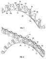
- Reference numeral 10essentially indicates a conventional roller drive chain for a bicycle or similar chain driven device.
- the drive chain 10essentially comprises outer chain links 12 and inner chain links 14 which are pivotally attached and connected to the outer chain links via bolts 16, 18.
- the outer chain links 12are alternately and overlapped with the inner chain links 14.
- the outer chain links 12include paired outer link plates 20, and the inner chain links include paired inner link plates 22.
- rollers 24are disposed about the bolts 16, 18.
- the plates 20, 22are provided with openings 30 at their ends 32.
- the bolts 16 and 18extend through and protrude from the apertures 30, although non-protruding bolts are generally considered optimal.
- the bolts 16 and 18are riveted at their ends 34, 36 during assembly of the roller chain 10. While the bolt 16 is made of a round rod, the bolt 18 may also be made of a tubular rod, as in the Fig. 2 Roller chain 10 shown reduced in size, which assists in determining the position of the roller chain 10, extends between the two circular ends 32 of each of the outer connecting plates 20 and the inner connecting plates 22nd
- the overlapping outer connectors 12 and inner connectors 14form corresponding and alternating outer connection spaces 40 and inner connection spaces 42.
- the outer connection spaces 40are openings defined by outer connection plates 20 and rollers 24 are set.
- the inner connection spaces 42are openings defined by the inner connection plates 22 and the rollers 24.
- the inner connecting spaces 42are substantially rectangular, wherein the longitudinal axis of the rectangle with the longitudinal axis A of the chain 10 (in the viewing direction Fig. 1 ) matches.
- the axial length of the inner connecting spaces 40is determined by the distance between the rollers 24, while the distance between the inner connecting plates 22 determines the transverse extent of the inner connecting spaces.
- the outer connection spaces 40have substantially the shape of a "cross” or in other words a "plus".
- the axial length of the outer connection spaces 40is determined by the distance between the rollers 24, while the distance between the outer connection plates 20 determines the transverse extent of the outer connection spaces.
- the transverse distance between the outer connecting plates 20is greater than the distance between the inner connecting plates 22. Since the transverse extent of the rollers 24 determines the spacing of the inner plates 22, the rollers define the transverse spacing D1 of the inner connecting plates 42. Similarly, since the outer plates 20 are positioned on the bolts 16 (or 18) on the outer sides of the inner link plates 22, the transverse distance D2 of the outer link plates 40 is determined by the sum of the transverse extent of the rollers 24 and the thickness of the two inner link plates ,
- a chain ring 50 having a known chain 10 shown for explanation of the background of the inventionis used.
- Chain ringstypically have a high number of teeth compared to sprocket cassettes, for example, 20 or more teeth.
- a crank or crank arm 48is attached to a typical position and to the chain ring 50 in a known manner.
- the crank side of the chain ring 50is in Fig. 3 shown, wherein the crank side is the outer side 54 of the chain ring.
- the outsideshows away from the vehicle to which the chain ring is attached.
- the opposite side of the outer side 54 of the chain ring 50is the inner side 56.
- the inner side 56points in the direction of the vehicle.
- the force applied to the crank arm 48causes rotation of the chain ring in one direction (clockwise).
- the rotation of the chain ring 50creates a pull on the chain 10, which is thus moved over the chain ring.
- the chain ring 50has a plurality of teeth 52 formed around the periphery 51 of the chain ring.
- the total number of varieties of teethis an even number.
- the plurality of teeth 52includes a first group of teeth 58 and a second group of teeth 60 arranged in an alternating manner. The number of first groups of teeth and second groups of teeth is the same.
- the first group of teeth 58which is adapted to be received by and for fitting in the outer connection spaces 40
- a second group of teeth 60is provided, which is adapted for receiving and for fitting in the inner connection spaces 42.
- the shape of the chain ring periphery 51may be substantially circular or non-circular, that is, for example, elliptical, oval, polygonal or parabolic. All examples of a chain ring are shown here with a circular periphery 51.
- Each tooth of the first group of teethis formed for engagement with the chain 10 via the outer connection spaces 40.
- Each tooth of the second group of teeth 60is formed for engagement with the chain 10 via the inner connection spaces 42.
- each tooth of the second group of teeth 60has a shape whose cross-sectional view is substantially rectangular, in particular at or near the base or root of the teeth.
- the cross-sectional viewresults from a section taken along a plane that is parallel to the top 80 of the teeth and extends through a base circle position of the teeth, ie, half the distance between the root circle and the outside circle.
- each tooth of the second group of teeth 60should be closely related to the formation of each of the internal connection spaces 42 (FIG. Fig. 1 ).
- the illustrated cross section of each tooth of the second set of teethshows the outside 54 as being substantially planar and the inside 56 also as being substantially planar.
- Each tooth of the second group of teeth 60can fill over approximately 75% of the axial distance D1 of a corresponding space in the chain 10.
- each tooth of the second set of teeth 60fills over approximately 80% of D 1 of the corresponding space in the chain 10.
- each tooth of the second group of teeth 60fills over approximately 85% of D 1 of the corresponding space in the chain 10.
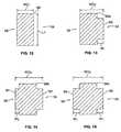
- each of the alternative variants of the teeth 58a, 58b, 58c of the first group of teeth 58(see Fig. 3 ) a shape that is in a cross-sectional view through the tooth, as in Fig. 12 is shown to have the same longitudinal length L T as the second group 60 (FIG. Fig. 12 ).
- Each tooth of the first tooth group 58can fill over approximately 75% of the distance D 2 of a corresponding space in the chain 10.
- each tooth of the first set of teeth 58fills over approximately 80% of D 2 of the corresponding space in the chain 10.
- each tooth of the first set of teeth 58performs over approximately 85% of D 2 of the corresponding space in the chain 10.
- Each tooth of the first group of teeth 58has an additional feature on the outside or a first projection 62 on the outside 54 of each alternative tooth 58a, 58b and 58c.
- the inside 56 of the tooth 58amay be the same (ie, without a protrusion) as the inside 56 of each of the second groups of teeth 60.
- the first protrusion 62is formed to fit into a corresponding part of the outer connecting spaces 40 of the chain 10 (FIG. Fig. 1 ) and has a width W 1 .
- the projection 62contributes to holding the chain 10 on the chain ring 50 (FIG. Fig. 3 ) at.
- the protrusion 62ensures that the total width WO 2 of each tooth 58 a around the extent of the projection 62 is greater than the overall width WO 1 .
- Fig. 14shows another embodiment of a tooth 58b of the first group of teeth 58.
- the tooth 58bis similar to that in Figs Fig. 13 formed teeth, with the additional feature of an inner or second projection 64 on the inside 56 of the teeth.
- the projection 64has a width W 2 which is smaller than the width W 1 of the projection 62 of the tooth 58 a, or alternatively greater than W 1 .
- the projections 62, 64ensure that the total width WO 3 of each tooth 58b is greater than the total width WO 1 of each tooth 60 by the extent of the projections 62, 64. Furthermore, WO 3 is greater than WO 2 .
- Fig. 15shows a further embodiment of a tooth 58c of the first group of teeth 58.
- the tooth 58cis similar to that in FIG Fig. 14 formed tooth, with an inner or second projection 66 on the inside 56 of the tooth.
- the projection 66has a width W 1 which is equal to the width W 1 of the projection 62 of the tooth 58 a.
- the protrusions 62, 66ensure that a total width WO 4 of each tooth 58 c around the extent of the protrusions 62, 66 is greater than the total width WO 1 of each tooth 60.
- WO 4is larger than WO 3 .
- teeth 58include protrusions provided along the side or sides of each tooth in a position to effectively assist in positioning the chain on the toothed ring 50, including positions that are close or at the base of each tooth or higher at each tooth 58.
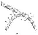
- the Fig. 4 and 6show an outer side 54 of the chain ring 50 and the drive direction DD.
- the first group of teeth 58is arranged alternately with the second group of teeth 60.
- the configuration of the second group of teeth 60may be defined with respect to the outsides and inner sides 54, 56 of each tooth 60 by forming an inner connection receiving recess 72 in the chainring 50 that reflects a material removed on the sides of the teeth 60.
- the inner connection receiving recess 72also serves to define the cross sectional shape of each tooth group 58.
- the inner connection receiving recess 72defines the outer sides and inner sides 54, 56 of each tooth and extends from the leading edge 68 of each of the tooth groups 58 to a trailing edge 70 of an adjacent tooth group 58 in drive direction DD.
- Each inner connection receiving recess 72is for receiving the length L P of an inner connecting plate 22 of the chain (FIG. Fig. 6 ) educated.
- Each recess 72has a base surface 72a extending in an axial direction and a wall 72b (FIG. Fig. 7 ) extending radially.
- the base surface 72amay have a slightly curved contour and may be formed substantially in the shape of a "U".
- Fig. 5shows the profile of each tooth of the teeth 58, 60 in detail.
- the inner connection receiving recess 72is formed in the chainring 50 and extends along the sides of each of the second groups of teeth 60 and from the loading side of a front or leading edge 68 of one of the groups of teeth 58 to a trailing edge 70 of an adjacent group of teeth 58 in the drive direction DD.
- the recess 72is designed to reduce the length L P (FIG. Fig. 6 ) of an inner connecting plate 22.
- Each toothmay have an upper surface 80.
- the base surface 72amay extend to the top surface 80 of each of the teeth 58.
- the leading edge 68 of each toothincludes a contact zone 74 on which a roller 24 (FIG. Fig. 1 ) touches the tooth.
- an optional tip section 76is provided above the contact zone 74.
- the roller 24does not contact the tip section 76 under normal driving conditions.
- the tip portion 76may project forward from a line drawn along the contact zone 74 by a distance T.
- the projecting tip portion 76provides a prior engagement of a chain link member than a chain without a tip portion and provides better guidance of the chain.
- An optional hook feature 78is a feature that may be formed on the trailing edge 70 of each tooth 58,60.
- the hook feature 78is positioned along the trailing edge 70 and may cooperate with the tip portion 76 to better guide the chain.
- the hook feature 78may include a portion of the trailing edge 70 that coincides with the radial direction R.
- each tooth of the first group of teeth 58 and the teeth of the second group of teeth 60 of the chain ring 50is arranged in an alternating manner.
- An optional feature of the teeth of each of the first set of teeth 58 and the second set of teeth 60is a corresponding outer chamfer 82a, 82b.
- Each tooth of the first group of teeth 58has an outer chamfer 82a, which may be a curved surface on the outside 54 or a shoulder of each tooth.
- Each tooth of the second group of teeth 60has an outer chamfer 82b, which may be a curved surface on the outside 54 or shoulder of each tooth.
- each tooth 60may have an extension C 1 which is greater relative to the extent C 2 of the outer chamfer 82 a of each tooth 58.
- the chain ring 50includes a chain 10 positioned and engaged thereon.
- Outer chain links 12are positioned on the first tooth tip 58.
- Inner chain links 14are positioned on the second group of teeth 60.
- the 10 and 11show a corresponding front view of the chain ring 50 without chain 10 and with chain.
- An optional feature of all the teeth 58, 60 of the chain ring 50is an offset OS of the mid point of the tooth tip or top 80 from the centerline CL toward the inside 56 of the chain ring. This offset feature provides better guidance of the chain on one side of the chainring.
- the link ring 50includes a number of teeth 58, 60.
- a link 1 of a chain engaged with the chain ring 50is represented by line L 1
- link 2 and link 3are represented respectively by lines L 2 , L 3 .
- Each line L 1-3draws the axes of each chain roller 24 between the centers.
- the hook feature 58is shown on the trailing edge 70 of each tooth 58, 60.
- the hook feature 78is positioned along the trailing edge 70 and may cooperate with the tip portion 76 of the leading edge 68 to better guide the chain.
- the hook feature 78may include a portion of the trailing edge 70 that coincide in the radial direction R.
- the hook feature 78has a radially outermost extent 78a, where the hook feature and the Connecting center lines L 1-3 intersect. Alternatively, the outermost extent 78a may be higher than the center lines L 1-3 so that there is more room for engaging the rollers in the teeth in the drive direction.
- the curved line 90is the path of the rollers 24 as they exit the engagement of the tooth.
- the chain 10is positioned on one of the first groups of teeth 58 with each of the outer chain links 12 and on one of the second groups of teeth 60 with each of the inner chain links 14.
- the chain ring 50is rotated by the crank 48, the chain 10 is pulled around the chain ring, and the outer chain links 12 and the inner chain links 14 are sequentially engaged with the respective first and second gear groups 58, 60.
- various features of the chain ring 50are for guiding and maintaining the chain on the chain ring.
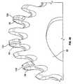
- protrusions 100are provided on the teeth 58 of the first group of teeth on the outside 102. These projections 100 are achieved in that on the inside 104 of the chain ring 50 oblong indentations 106 are made. When attaching these indentations 106, the material of the teeth 58 of the first group of teeth is set in a flow state and the protrusions 100 are formed by a suitable shape. These extend as you go in FIG. 19 The size of the projections 100 is determined by the size of the indentations 106 and, of course, by the shape on the outside of the teeth 58.
- the protrusion 100 on the teeth 58 of the first group of teethintroduces an imposed chain inwardly against a chain shedding, thus improving the chain guiding characteristics.
- FIG. 20shows a further embodiment of the invention, in which the chain ring 50 is substantially the chain ring 50 of the embodiment according to the Figures 17-19 equivalent.
- a further projection 108is provided above the indentation 106 on the inside of the teeth 58. This too is produced by material deformation. Also for this further projection 108 on the Inside the teeth 58 of the first group of teeth material may be used which is deformed by the indentation 106.
- This further projection 108is formed like a reinforced burr and prevents the misplacement of the chain, because the inner straps of the chain on the widened in the region of the tooth head teeth of the first group of teeth no longer fit.
- FIGS. 21 to 25show a further embodiment of the invention, wherein the explanation focuses on the representation of different views and sectional views of a tooth 58 of the first group of teeth.
- this specially designed tooth 58exemplifies teeth of the first group of teeth provided on a chain ring 50 of the type described above.
- These teeth 58also have indentations 106.
- these teeth 58 on both sides, ie on the inside and on the outside, corresponding indentations 106have.
- the impressions 106are elongated. By such an impression 106 material is displaced during the forming process. This flows and deforms into protrusions 110, 112.
- the protrusions 110, 112each extend longitudinally along the embossment 106 and surround it with curved sections 114, 116 in a head region of the tooth 58.
- FIGS. 23 to 25show that the indentations 106 are partially surrounded by the projections 110, 112. They also show how deep the indentations 106 penetrate into the tooth 58 and to what extent the projections 110, 112 protrude.
- the toothmay, in principle, assume more than 20% up to 50% of its actual thickness without deformation, independently of the specific embodiments described in detail above. In the region of the lowest point of the indentations 106, the tooth can be reduced to up to 30% of its original thickness.
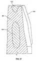
- Figures 26 and 27show a further embodiment of the invention.
- the teeth 58 of the first group of teeth of the chain ring 50are provided on the outside and on its inside with a coating 120 of applied glass fiber reinforced plastic material.
- the desired protrusionsare achieved on both sides of the teeth 58 on their outside and inside.
- the sectional view according to FIG. 27detects, have the teeth 58 of the first group of teeth in its radially outer region a recess 122 and in its central region a recess 124.
- These recessesallow the plastic material of the coating 120 to not only surround the outside and inside of the teeth 58, but also to extend through the teeth 58 through the recesses 122 and 124. This can ensure that the glass fiber reinforced plastic material of the coating 120 remains safe, durable and reliable on the teeth 58.
- additional materialsuch as fiberglass-reinforced plastic material of the coating 120 in the example, makes it possible to produce projections of any shape with little manufacturing effort and at low cost.
- additional materialsuch as fiberglass-reinforced plastic material of the coating 120 in the example.
- metal materialcan also be applied by build-up welding or soldering by way of order soldering.
- As a basic bodycan be an easy to judge, use flat hardened steel chain ring, which has high wear resistance and is inexpensive to produce.
Landscapes
- Engineering & Computer Science (AREA)
- General Engineering & Computer Science (AREA)
- Mechanical Engineering (AREA)
- Chemical & Material Sciences (AREA)
- Combustion & Propulsion (AREA)
- Transportation (AREA)
- Gears, Cams (AREA)
- Devices For Conveying Motion By Means Of Endless Flexible Members (AREA)
Abstract
Translated fromGermanDescription
Translated fromGermanDie vorliegende Erfindung betrifft Kettenräder bzw. Kettenringe, und insbesondere Einzelkettenringe zur Verwendung mit einer bekannten Kette in einem Fahrradantriebstrangsystem, das eine Fahrradkurbel umfasst. Fahrräder und andere kettenangetriebene Fahrzeuge verwenden in der Regel einen oder mehrere Kettenringe und einen Satz von an einer hinteren Narbe angebrachten Ritzeln, die mit dem Kettenring über eine Kette verbunden sind. Es werden verschiedene Mechanismen zum Halten der Kette an dem Kettenring und den Ritzeln verwendet. Diese Mechanismen umfassen Kettensicherungen, Kettenspanner, Kettenfänger, Schaltwerkanordnungen und dergleichen.The present invention relates to sprockets, and more particularly to single chain rings for use with a known chain in a bicycle powertrain system including a bicycle crank. Bicycles and other chain-driven vehicles typically use one or more chain rings and a set of rear scar-mounted pinions connected to the chain ring via a chain. Various mechanisms are used to hold the chain on the chainring and the pinions. These mechanisms include chain locks, chain tensioners, chain catchers, derailleur assemblies, and the like.
Während des Fahrens eines Fahrrads mit einem kettengetriebenen Antriebsstrang ist die Handhabung der Kette und der Kettenringeingriff für einen sicheren und effektiven Antrieb des Fahrrads besonders wichtig. Die Kette mit dem Kettenring in Eingriff zu halten, kann schwierig sein. Insbesondere bei Fahrrädern mit Gangschaltungen können erhebliche Veränderungen in der Kettenspannung und dynamische Bewegungen der Kette auftreten, vor allem während des Fahrens im Gelände.While riding a bicycle with a chain drive train, chain handling and chainring engagement are particularly important for safe and effective drive of the bicycle. Keeping the chain engaged with the chainring can be difficult. Significant changes in the chain tension and dynamic movements of the chain, especially during off-road driving, can occur especially in bicycles with gears.
Darüber hinaus kann der Kettenring bei jedem Fahrrad die Kettenstrebe des Fahrradrahmens berühren, wenn sich die Kurbel in einer Position befindet, in der hohe Lasten von dem Fahrer ausgeübt werden, was eine elastische Deformation des Fahrradrahmens und der Kurbelanordnung verursacht. Dies kann zu Schäden an dem Rahmen und an dem Kettenring führen und andere Probleme verursachen.In addition, the chainring on each bicycle may contact the chainstay of the bicycle frame when the crank is in a position where high loads are exerted by the rider, causing elastic deformation of the bicycle frame and the crank assembly. This can cause damage to the frame and the chainring and cause other problems.
Aus dem Stand der Technik ist eine Vielzahl von Kettenrädern, Kettenringen aber auch Ritzeln bekannt, bei denen die Zähne lokal deformiert sind, um Steighilfen für die Kette zu ermöglichen oder um die Kettenführungseigenschaften zu verbessern.From the prior art, a variety of sprockets, chain rings but also sprockets are known in which the teeth are locally deformed to allow climbing aids for the chain or to improve the chain guiding properties.
Beispielsweise wird auf das Dokument
Das Dokument
Das Dokument
Das Dokument
Schließlich zeigt das Dokument
Der vorstehend beschriebene Stand der Technik hat einerseits Nachteile, insbesondere weil die Fertigung aufwändig und damit kostenintensiv ist, und unterliegt darüber hinaus dem Problem, dass sich nicht zuverlässig und dauerhaft die gewünschten Kettenführungseigenschaften einstellen.On the one hand, the prior art described above has disadvantages, in particular because the production is complicated and thus expensive, and is also subject to the problem that the desired chain guidance properties are not reliably and permanently established.
Die Erfindung setzt sich zur Aufgabe, einen Kettenring bereitzustellen, der eine verbesserte Antriebskettenhandhabung ermöglicht, insbesondere für Fahrräder, die erfolgreich und zuverlässig im groben und anspruchsvollen Gelände gefahren werden, wobei die Herstellung des erfindungsgemäßen Kettenrings einfach und kostengünstig bei hoher Funktionalität und Lebensdauer des Kettenrings erfolgt.The invention has for its object to provide a chain ring, which allows improved drive chain handling, especially for bicycles that are driven successfully and reliably in rough and challenging terrain, the production of the chain ring according to the invention is simple and inexpensive with high functionality and life of the chain ring ,
Diese Aufgabe wird durch einen Kettenring mit den Merkmalen des Patentanspruchs 1 gelöst.This object is achieved by a chain ring with the features of
Weiterbildungen der Erfindung finden sich in den abhängigen Ansprüchen und in der nachfolgenden Beschreibung wieder.Further developments of the invention can be found in the dependent claims and in the following description.
Die vorliegende Erfindung stellt gemäß einer Ausführungsform einen Einzelkettenring für eine Fahrradvorderkurbelanordnung zum Eingreifen in eine Antriebskette bereit. Der Einzelkettenring, wobei "Einzel" nur einen einzigen bedeutet, umfasst eine um den Umfang des Kettenrings ausgebildete Vielzahl von Zähnen, wobei die Vielzahl der Zähne eine gerade Anzahl an Zähnen aufweist. Die Vielzahl der Zähne umfasst eine erste Zahngruppe und eine zweite Zahngruppe, die alternierend zwischen der ersten Zahngruppe angeordnet ist. Die Anzahl der ersten Zahngruppe und der zweiten Zahngruppe ist gleich. Jede erste und zweite Zahngruppe umfasst eine Außenseite und eine Innenseite, die der Außenseite entgegengesetzt ist. Jeder Zahn der ersten Zahngruppe umfasst wenigstens einen ersten Vorsprung an der Außenseite, und jeder Zahn der zweiten Zahngruppe ist ohne einen Vorsprung ausgebildet. Erfindungsgemäß ist ferner vorgesehen, dass der erste Vorsprung von einer Materialverformung an der Außenseite gebildet ist, die von der Innenseite oder von der Außenseite ausgehend erreicht wird. Alternativ ist erfindungsgemäß vorgesehen, dass der erste Vorsprung von einem Materialauftrag an der Außenseite gebildet ist.The present invention, according to one embodiment, provides a single chainring for a bicycle front crank assembly for engaging a drive chain. The single chain ring, where "single" means only a single one, encompasses one the plurality of teeth formed in the circumference of the chain ring, the plurality of teeth having an even number of teeth. The plurality of teeth includes a first group of teeth and a second group of teeth alternately arranged between the first group of teeth. The number of the first group of teeth and the second group of teeth is the same. Each first and second group of teeth includes an outer side and an inner side that is opposite to the outer side. Each tooth of the first tooth group includes at least a first protrusion on the outside, and each tooth of the second tooth group is formed without a protrusion. According to the invention it is further provided that the first projection is formed by a material deformation on the outside, which is achieved starting from the inside or from the outside. Alternatively, the invention provides that the first projection is formed by a material application on the outside.
Bei der ersten Erfindungsalternative wird der Kettenring einfach durch lokale Materialumformung derart bearbeitet, dass sich die gewünschten Vorsprünge an der ersten Zahngruppe ausbilden. Umfangreiche Umformbearbeitungsvorgänge, die sich etwa über den gesamten Umfang des Kettenrings ergeben, sind nicht erforderlich. Dadurch lässt sich die Grundstruktur des Kettenrings erhalten und nur dort an dieser durch Umformbearbeitung eingreifen, wo auch tatsächlich zum Erreichen verbesserter Kettenführungseigenschaften Eingriffe erforderlich sind, nämlich an den Zähnen der ersten Zahngruppe.In the first alternative of the invention, the chain ring is simply machined by local material forming such that the desired projections form on the first group of teeth. Extensive forming operations that occur over the entire circumference of the chain ring are not required. As a result, the basic structure of the chain ring can be obtained and intervene only at this by forming processing, where actually to achieve improved chain guide properties interventions are required, namely on the teeth of the first group of teeth.
Das gleiche Prinzip gilt für die zweite Erfindungsalternative, bei der lokal Materialauftrag erfolgt, beispielsweise durch An- oder Umspritzen, Auftragsschweißen oder Aufbringen von Lotmaterial, um die Zähne der ersten Zahngruppe in dem mit der Kette zusammenwirkenden Bereichen breiter auszugestalten. Auch bei dieser Erfindungsalternative muss der Kettenring nur lokal durch Materialauftrag bearbeitet werden.The same principle applies to the second invention alternative, in which material is applied locally, for example by coating or encapsulation, build-up welding or application of solder material in order to make the teeth of the first group of teeth broader in the area interacting with the chain. Even with this invention alternative, the chain ring must be processed only locally by applying material.
Beide Erfindungsalternativen bieten den Vorteil eines relativ geringen Bearbeitungsaufwands mit dem Ergebnis deutlich verbesserter Kettenführungseigenschaften gegenüber dem Stand der Technik.Both invention alternatives offer the advantage of a relatively low processing cost with the result of significantly improved chain guiding properties over the prior art.
Die Erfindung kann ferner einen Einzelkettenring der vorstehend beschriebenen Art für eine Fahrradvorderkurbelanordnung für den Eingriff in eine Antriebskette bereitstellen, wobei die Antriebskette überlappend angeordnete innere und äußere Verbindungselemente umfasst, wobei der Kettenring eine um einen Umfang des Kettenrings ausgebildete Vielzahl von Zähnen aufweist, und die Vielzahl an Zähnen eine gerade Anzahl an Zähnen aufweist. Die Vielzahl der Zähne umfasst eine erste Zahngruppe und eine zweite Zahngruppe, die alternierend zwischen der ersten Zahngruppe angeordnet ist. Die erste Zahngruppe und die zweite Zahngruppe sind von der Anzahl her gleich. Jede erste Zahngruppe und zweite Zahngruppe umfasst eine Außenseite und eine Innenseite, die der Außenseite entgegengesetzt ist. Jede Außenseite und jede Innenseite jeder zweiten Zahngruppe definiert eine in dem Kettenring entlang der zweiten Zahngruppe ausgebildete Ausnehmung.The invention may further provide a single chain ring of the type described above for a bicycle front crank assembly for engaging a drive chain, the drive chain comprising overlapping inner and outer links, the chain ring being formed around a circumference of the chain Chain ring formed plurality of teeth, and the plurality of teeth having an even number of teeth. The plurality of teeth includes a first group of teeth and a second group of teeth alternately arranged between the first group of teeth. The first group of teeth and the second group of teeth are equal in number. Each first group of teeth and second group of teeth includes an outer side and an inner side that is opposite to the outer side. Each outside and inside of each second group of teeth defines a recess formed in the chain ring along the second group of teeth.
Die Erfindung betrifft ferner eine Fahrradkurbelanordnung, die einen Fahrradkurbelarm und einen Einzelkettenring der vorstehend beschriebenen Art umfasst, der an dem Fahrradkurbelarm angebracht und mit einer Antriebskette in Eingriff bringbar ist. Der Einzelkettenring umfasst eine um einen Umfang des Kettenrings ausgebildete Vielzahl von Zähnen, wobei die Vielzahl von Zähnen eine gerade Anzahl an Zähnen aufweist. Die Vielzahl der Zähne umfasst eine erste Zahngruppe und eine zweite Zahngruppe, die alternierend zwischen der ersten Zahngruppe angeordnet ist. Die erste Zahngruppe und die zweite Zahngruppe sind von ihrer Anzahl her gleich. Jede erste und zweite Zahngruppe umfasst eine Außenseite und eine Innenseite, die der Außenseite entgegengesetzt ist. Jeder Zahn der ersten Zahngruppe umfasst wenigstens einen Vorsprung an der Außenseite und jeder Zahn der zweiten Zahngruppe ist ohne einen ersten Vorsprung an der Außenseite und der Innenseite ausgebildet.The invention further relates to a bicycle crank assembly comprising a bicycle crank arm and a single chainring of the type described above, which is attached to the bicycle crank arm and engageable with a drive chain. The single chain ring includes a plurality of teeth formed around a circumference of the chain ring, the plurality of teeth having an even number of teeth. The plurality of teeth includes a first group of teeth and a second group of teeth alternately arranged between the first group of teeth. The first group of teeth and the second group of teeth are equal in number. Each first and second group of teeth includes an outer side and an inner side that is opposite to the outer side. Each tooth of the first tooth group includes at least one protrusion on the outside, and each tooth of the second tooth group is formed without a first protrusion on the outside and the inside.
Der voranstehend beschriebene Kettenring kann gemäß einer Ausführungsform einen zweiten Vorsprung an der Innenseite der ersten Zahngruppe aufweisen. Dabei kann vorgesehen sein, dass der zweite Vorsprung von einer Materialverformung an der Außenseite gebildet ist, die von der Innenseite oder von der Außenseite ausgehend hergestellt ist, oder von einer Materialauftrag an der Außenseite.The chain ring described above may, according to one embodiment, have a second projection on the inside of the first group of teeth. It can be provided that the second projection is formed by a material deformation on the outside, which is made from the inside or from the outside, or by a material application on the outside.
Bei dem Kettenring der voranstehend beschriebenen Art kann gemäß einer Ausführungsform der vorliegenden Erfindung ferner vorgesehen sein, dass der erste Vorsprung eine erste Breite und der zweite Vorsprung eine zweite Breite hat, wobei die erste Breite gleich der zweiten Breite ist. Alternativ kann gemäß einer Weiterbildung der Erfindung die erste Breite größer als die zweite Breite sein oder umgekehrt.In the chainring of the above-described type, according to an embodiment of the present invention, it may be further provided that the first protrusion has a first width and the second protrusion has a second width, wherein the first width is equal to the second width. Alternatively, according to an embodiment of the invention, the first width may be greater than the second width or vice versa.
Bezüglich der ersten Erfindungsalternative kann vorgesehen sein, dass der erste oder/und der zweite Vorsprung durch Einprägen hergestellt ist, wobei Material des Zahns von der einen Seite eingeprägt und zum Ausbilden des Vorsprungs auf der anderen Seite des Zahns aus dem Zahn in der gewünschten Form "herausgedrückt" ist. Dies geschieht dadurch, dass etwa ein Umformwerkzeug auf der einen Seite des Zahns angesetzt wird und den Zahn lokal deformiert, so dass am Zahn eine Ausnehmung, Einpragung oder Vertiefung entsteht. Dadurch wird erreicht, dass Material in gewünschter Weise auf die andere Seite des Zahns zum Erzielen des Vorsprungs fließt.With regard to the first alternative of the invention, provision may be made for the first or / and the second projection to be produced by impressing, wherein material of the Tooth is impressed from one side and "pressed out" to form the projection on the other side of the tooth from the tooth in the desired shape. This happens because approximately a forming tool is attached to one side of the tooth and locally deforms the tooth, so that the tooth is formed a recess, indentation or depression. It is thereby achieved that material flows in a desired manner on the other side of the tooth for achieving the projection.
Eine Weiterbildung der Erfindung sieht vor, dass der zweite Vorsprung durch Materialumformung oberhalb der Einprägung für den erste Vorsprung vorgesehen ist.A development of the invention provides that the second projection is provided by material deformation above the impression for the first projection.
Alternativ zu der vorstehend beschriebenen Fertigungsmöglichkeit des Einprägens und "Durchdrückens" von Zahnmaterial von der einen Zahnseite zur anderen sieht eine Weiterbildung der Erfindung vor, dass der erste oder/und der zweite Vorsprung durch Einprägen hergestellt ist, wobei Material des Zahns an der einen Seite des Zahns lokal eingeprägt wird, so dass zum Ausbilden des wenigstens einen Vorsprungs Material auf derselben Seite des Zahns nahe der lokalen Einprägung hervortritt. Bei dieser Erfindungsvariante wird also das Material nicht sozusagen durch den Zahn hindurch gedrückt, sondern lokal deformiert, so dass es seitlich der Deformation auf derselben Seite des Zahns zum Ausbilden des Vorsprungs hervortritt.As an alternative to the above-described production possibility of impressing and "pushing" tooth material from one tooth side to the other, a development of the invention provides that the first and / or the second projection is produced by impressing, wherein material of the tooth on one side of the Tooth is impressed locally, so that for forming the at least one projection material on the same side of the tooth emerges near the local imprint. In this variant of the invention, therefore, the material is not forced so to speak through the tooth, but locally deformed so that it emerges laterally from the deformation on the same side of the tooth to form the projection.
Eine Weiterbildung diese Erfindungsvariante sieht vor, dass zum Ausbilden zweier Vorsprünge auf ein und derselben Seite des Zahns Material beidseits der lokalen Einprägung hervortritt. Mit anderen Worten wird der Zahn lokal derart durch Einprägen deformiert, dass das Material beim Umformen in einen Bereich beidseits der Einprägung verdrängt wird und sich dort zum Ausbilden der beiden Vorsprünge auf derselben Seite des Zahns auswölbt. Dabei ist es möglich, dass sich zwei im Wesentlichen lineare Vorsprünge entlang der Einprägung ergeben, wenn Letztere länglich ausgebildet ist. Eine Weiterbildung der Erfindung sieht vor, dass sich das hervortretende, wenigstens einen Vorsprung bildende Material zumindest abschnittsweise um die lokale Einprägung herum erstreckt. So lassen sich auch komplexere Vorsprungsstrukturen erzielen.A development of this variant of the invention provides that for forming two projections on one and the same side of the tooth material emerges on both sides of the local impression. In other words, the tooth is locally deformed by impressing that the material is displaced during forming in a region on both sides of the indentation and bulges there to form the two projections on the same side of the tooth. It is possible that there are two substantially linear projections along the embossing, when the latter is elongated. A development of the invention provides that the protruding material forming at least one projection extends at least in sections around the local impression. This also allows more complex projection structures to be achieved.
Hinsichtlich der Dimensionen kann im tiefsten Bereich der Einprägung bzw. der einander gegenüberliegenden Einprägung auf der Außenseite und der Innenseite des jeweiligen Zahns die Dicke des Zahns auf bis zu 30 % seiner ursprünglichen Dicke reduziert sein. Im Bereich des wenigstens einen Vorsprungs kann die Dicke des Zahns um 30 - 50 % vergrößert sein.In terms of dimensions, in the deepest area of the indentation on the outside and inside of each tooth, the thickness of the tooth may be up to 30% of its original thickness be reduced. In the region of the at least one projection, the thickness of the tooth can be increased by 30-50%.
Die Einprägung kann sich auf einen lokalen Bereich beschränken oder kann in einer radialen Länge ausgeführt sein, die sich über 30 % bis zu 100 % der radialen Höhe des Zahns erstreckt. Die Vorsprünge sind vorzugsweise gerundet ausgebildet und es werden scharfe Kanten vermieden. Gleiches gilt für die Ausgestaltung der Einprägungen.The indentation may be limited to a local area or may be implemented in a radial length extending over 30% up to 100% of the radial height of the tooth. The projections are preferably rounded and sharp edges are avoided. The same applies to the design of the impressions.
Bezüglich der vorstehend erwähnten zweiten Erfindungsalternative des Materialauftrags kann vorgesehen sein, dass der Materialauftrag aus Metall oder einem Kunststoffmaterial oder einem Kunstharzmaterial, vorzugsweise einem faserverstärkten Kunststoffmaterial oder einem faserverstärkten Kunstharzmaterial hergestellt ist. So kann der Materialauftrag durch Auftragsschweißen, Auftragslöten oder durch lokales Anbringen des Kunststoffmaterials bzw. Kunstharzmaterials erreicht werden.With regard to the above-mentioned second alternative of the invention of material application, it may be provided that the material application is made of metal or a plastic material or a synthetic resin material, preferably a fiber-reinforced plastic material or a fiber-reinforced synthetic resin material. So the material application can be achieved by build-up welding, order soldering or by local application of the plastic material or synthetic resin material.
Zur Fixierung des aufgetragenen Materials kann der Zahn lokal aufgeraut werden. Bevorzugt ist erfindungsgemäß jedoch vorgesehen, dass der Zahn im Bereich des Materialauftrags mit wenigstens einer Ausnehmung oder/und wenigstens einem Durchbruch versehen ist, in die bzw. in den sich das aufgetragene Material zumindest Abschnittsweise hinein erstreckt. Dadurch lässt sich das aufgetragene Material besser am Zahn oder sogar im Zahn verankern.To fix the applied material, the tooth can be roughened locally. Preferably, however, according to the invention it is provided that the tooth is provided in the area of the material application with at least one recess and / or at least one opening, into which or in which the applied material extends at least in sections. This makes it easier to anchor the applied material to the tooth or even to the tooth.
Eine Weiterbildung der Erfindung sieht vor, dass jede Außenseite und jede Innenseite jeder zweiten Zahngruppe eine in dem Kettenring entlang jeder zweiten Zahngruppe ausgebildete Ausnehmung definiert.A development of the invention provides that each outer side and each inner side of each second tooth group defines a recess formed in the chain ring along every second tooth group.
Bei dem voranstehend beschriebenen Kettenring kann gemäß einer Weiterbildung der Erfindung ferner vorgesehen sein, dass jeder Zahn der ersten Zahngruppe und der zweiten Zahngruppe eine vordere Flanke umfasst, wobei die vordere Flanke einen vorstehenden Spitzenabschnitt umfasst, der zum Führen der Kette ausgebildet ist.In the case of the chain ring described above, according to a development of the invention, it can further be provided that each tooth of the first tooth group and the second tooth group comprises a front flank, wherein the front flank comprises a projecting tip section, which is designed to guide the chain.
Bei dem voranstehend beschriebenen Kettenring kann gemäß einer Ausführungsform der Erfindung ferner vorgesehen sein, dass jeder Zahn der ersten Zahngruppe und der zweiten Zahngruppe eine hintere Flanke umfasst, wobei die hintere Flanke einen Hakenabschnitt umfasst, der zum Führen der Kette ausgebildet ist.In the chain ring described above, according to an embodiment of the invention, it may further be provided that each tooth of the first group of teeth and the second group of teeth includes a trailing edge, the trailing edge comprising a hook portion adapted to guide the chain.
Bei dem Kettenring der voranstehend beschriebenen Art kann gemäß einer Weiterbildung der Erfindung ferner vorgesehen sein, dass jeder Zahn der ersten Zahngruppe und der zweiten Zahngruppe eine vordere Flanke und eine hintere Flanke umfasst, wobei die vordere Flanke von jedem Zahn einen vorstehenden Spitzenabschnitt umfasst.In the chain ring of the type described above, according to a further development of the invention, it can further be provided that each tooth of the first tooth group and the second tooth group comprises a front flank and a rear flank, wherein the front flank of each tooth comprises a projecting tip section.
Bei dem voranstehend beschriebenen Kettenring kann gemäß einer Weiterbildung der Erfindung ferner vorgesehen sein, dass die hintere Flanke jedes Zahns einen Hakenabschnitt umfasst.In the chain ring described above, according to an embodiment of the invention may further be provided that the trailing edge of each tooth comprises a hook portion.
Bei dem voranstehend beschriebenen Kettenring kann gemäß einer Ausführungsform der Erfindung der Hakenabschnitt einen im Wesentlichen radial orientierten Abschnitt umfassen.In the chain ring described above, according to an embodiment of the invention, the hook portion may comprise a substantially radially oriented portion.
Bei dem voranstehend beschriebenen Kettenring kann gemäß einer Weiterbildung der Erfindung vorgesehen sein, dass der vorstehende Spitzenabschnitt und ein Hakenabschnitt eines benachbarten Zahns zum Führen der Kette zusammenwirken.In the chain ring described above may be provided according to an embodiment of the invention that the projecting tip portion and a hook portion of an adjacent tooth cooperate to guide the chain.
Bei dem Kettenring der voranstehend beschriebenen Art kann gemäß einer Weiterbildung der Erfindung ferner vorgesehen sein, dass jeder Zahn der ersten Zahngruppe eine radial äußere Fase umfasst, die eine erste Erstreckung entlang der Außenseite jedes Zahnes aufweist.In the case of the chain ring of the type described above, according to an embodiment of the invention, it can further be provided that each tooth of the first tooth group comprises a radially outer chamfer which has a first extent along the outside of each tooth.
Bei dem Kettenring der voranstehend beschriebenen Art kann gemäß einer Weiterbildung der Erfindung ferner vorgesehen sein, dass jeder Zahn der zweiten Zahngruppe eine radial äußere Fase umfasst, die eine zweite Erstreckung entlang der Außenseite jedes Zahnes hat.In the chain ring of the type described above, according to a development of the invention, it can further be provided that each tooth of the second tooth group comprises a radially outer chamfer which has a second extent along the outside of each tooth.
Bei dem Kettenring der voranstehend beschriebenen Art kann gemäß einer Weiterbildung der Erfindung ferner vorgesehen sein, dass jeder Zahn der ersten Zahngruppe eine äußere Fase mit einer ersten Erstreckung umfasst, und jeder Zahn der zweiten Zahngruppe eine äußere Fase mit einer zweiten Umstreckung umfasst, und die erste Erstreckung kleiner als die zweite Erstreckung ist.In the chain ring of the type described above, according to a further development of the invention, it can further be provided that each tooth of the first tooth group comprises an outer chamfer having a first extent, and each tooth of the second tooth group comprises an outer chamfer having a second extent, and the first Extension is smaller than the second extension.
Bei dem Kettenring der voranstehend beschriebenen Art kann gemäß einer Weiterbildung der Erfindung ferner vorgesehen sein, dass jede der Innenseiten und der Außenseiten jeder zweiten Zahngruppe eine in dem Kettenring ausgebildete Ausnehmung definieren.In the chain ring of the type described above can be further provided according to a development of the invention that define each of the inner sides and the outer sides of each second group of teeth formed in the chain ring recess.
Bei dem voranstehend beschriebenen Kettenring kann gemäß einer Weiterbildung der Erfindung ferner vorgesehen sein, dass jede Ausnehmung durch eine sich axial erstreckende Basisfläche und eine sich radial erstreckende Wand definiert wird.In the chain ring described above, according to an embodiment of the invention may further be provided that each recess is defined by an axially extending base surface and a radially extending wall.
Die Erfindung betrifft ferner einen Einzelkettenring für eine Fahrradvorderkurbelanordnung zum Eingreifen in eine Antriebskette, wobei die Antriebskette überlappend angeordnete innere und äußere Verbindungselemente umfasst, wobei der Kettenring in der vorstehend beschriebenen Art ausgebildet ist..The invention further relates to a single chainring for a bicycle front crank assembly for engaging in a drive chain, wherein the drive chain comprises overlapping arranged inner and outer connecting elements, wherein the chain ring is formed in the manner described above.
Die vorliegende Erfindung betrifft ferner eine Fahrradkurbelanordnung, aufweisend: einen Fahrradkurbelarm; und
einen Einzelkettenring der vorstehend beschriebenen Art, der an dem Fahrradkurbelarm angebracht ist, und mit einer Antriebskette in Eingriff bringbar ist.The present invention further relates to a bicycle crank assembly, comprising: a bicycle crank arm; and
a single chain ring of the type described above, which is mounted on the bicycle crank arm, and is engageable with a drive chain.
Diese und andere Merkmale und Vorteile der vorliegenden Erfindung werden von der nachstehenden Beschreibung einer oder mehrerer Ausführungsformen der vorliegenden Erfindung mit Bezug auf die beigefügten Figuren ersichtlich.These and other features and advantages of the present invention will become apparent from the following description of one or more embodiments of the present invention with reference to the accompanying drawings.
Es stellen dar:
- Fig. 1
- eine Draufsicht einer herkömmlichen Antriebskette;
- Fig. 2
- eine Seitenansicht der herkömmlichen Antriebskette gemäß
Fig. 1 ; - Fig. 3
- eine isometrische Ansicht einer Kombination der Antriebskette und eines Kettenrings zur einführenden Erläuterung der Erfindung, die miteinander in einem Antriebsstrang in Eingriff stehen;
- Fig. 4
- eine Seitenansicht des Kettenrings aus
Figur 3 ; - Fig. 5
- eine vergrößerte Ansicht des Kettenrings gemäß
Fig. 4 ; - Fig. 6
- eine Seitenansicht einer Kombination einer Antriebskette und eines Kettenrings gemäß zur Erläuterung der vorliegenden Erfindung, die mit einer Antriebskette mit entfernten äußeren Verbindungsplatten in Eingriff steht;
- Fig. 7
- eine isometrische Vorderansicht des Kettenrings aus
Fig. 6 ; - Fig. 8
- eine isometrische Vorderansicht des Kettenrings gemäß
Fig. 7 , im Eingriff mit einer Antriebskette; - Fig. 9
- eine isometrische Rückansicht des Kettenrings gemäß
Fig. 7 , im Eingriff mit einer Antriebskette; - Fig. 10
- eine Vorderansicht des Kettenrings aus
Fig. 9 ; - Fig. 11
- eine Vorderansicht des Kettenrings aus
Fig. 10 im Eingriff mit einer Antriebskette; - Fig. 12
- eine Querschnittsansicht entlang der Schnittlinie B-B gemäß
Fig. 5 eines Typs eines Zahnradzahns gemäß einer Zahngruppe; - Fig. 13-15
- Querschnittsansichten entlang der Schnittlinie A-A gemäß
Fig. 5 von alternativen Varianten eines Zahnradzahns, die sich von dem Zahn gemäßFig. 12 unterscheiden und gemäß einer anderen Zahngruppe ausgebildet sind; - Fig. 16
- eine teilweise Seitenansicht des Kettenrings zur Erläuterung der Erfindung mit den Rollen einer Kette im Eingriff mit den Zähnen des Kettenrings;
- Fig. 17
- eine perspektivische Ansicht einer ersten Ausführungsform eines erfindungsgemäßen Kettenrings;
- Fig. 18
- eine weitere perspektivische Ansicht der ersten Ausführungsform des erfindungsgemäßen Kettenrings;
- Fig. 19
- eine weitere perspektivische Ansicht der ersten Ausführungsform des erfindungsgemäßen Kettenrings;
- Fig. 20
- eine perspektivische Ansicht einer zweiten Ausführungsform des erfindungsgemäßen Kettenrings;
- Fig. 21
- eine perspektivische Ansicht eines Zahns einer dritten Ausführungsform des erfindungsgemäßen Kettenrings;
- Fig. 22
- eine Schnittansicht durch den Zahn aus
Figur 21 entlang der Schnittlinie I-I; - Fig. 23
- eine Draufsicht auf den Zahn aus
Figur 21 ; - Fig. 24
- eine Schnittansicht durch den Zahn aus
Figur 21 entlang der Schnittlinie II-II; - Fig. 25
- eine Schnittansicht durch den Zahn aus
Figur 21 entlang der Schnittlinie III-III; - Fig. 26
- eine perspektivische Ansicht eines Zahns einer vierten Ausführungsform des erfindungsgemäßen Kettenrings, und
- Fig. 27
- eine perspektivische Querschnittsansicht durch einen Zahn entlang der Schnittlinie IV aus
Figur 26 .
- Fig. 1
- a plan view of a conventional drive chain;
- Fig. 2
- a side view of the conventional drive chain according to
Fig. 1 ; - Fig. 3
- an isometric view of a combination of the drive chain and a chain ring for an introductory explanation of the invention, which are engaged with each other in a drive train;
- Fig. 4
- a side view of the chain ring
FIG. 3 ; - Fig. 5
- an enlarged view of the chain ring according to
Fig. 4 ; - Fig. 6
- a side view of a combination of a drive chain and a chain ring according to the explanation of the present invention, which is in engagement with a drive chain with remote outer connection plates;
- Fig. 7
- an isometric front view of the chain ring
Fig. 6 ; - Fig. 8
- an isometric front view of the chain ring according to
Fig. 7 in engagement with a drive chain; - Fig. 9
- an isometric rear view of the chain ring according to
Fig. 7 in engagement with a drive chain; - Fig. 10
- a front view of the chain ring
Fig. 9 ; - Fig. 11
- a front view of the chain ring
Fig. 10 engaged with a drive chain; - Fig. 12
- a cross-sectional view along the section line BB according to
Fig. 5 a type of gear tooth according to a group of teeth; - Fig. 13-15
- Cross-sectional views along the section line AA according to
Fig. 5 alternative variants of a gear tooth extending from the tooth according toFig. 12 differ and are formed according to another group of teeth; - Fig. 16
- a partial side view of the chain ring for explaining the invention with the rollers of a chain in engagement with the teeth of the chain ring;
- Fig. 17
- a perspective view of a first embodiment of a chain ring according to the invention;
- Fig. 18
- a further perspective view of the first embodiment of the chain ring according to the invention;
- Fig. 19
- a further perspective view of the first embodiment of the chain ring according to the invention;
- Fig. 20
- a perspective view of a second embodiment of the chain ring according to the invention;
- Fig. 21
- a perspective view of a tooth of a third embodiment of the chain ring according to the invention;
- Fig. 22
- a sectional view through the tooth
FIG. 21 along the section line II; - Fig. 23
- a top view of the tooth
FIG. 21 ; - Fig. 24
- a sectional view through the tooth
FIG. 21 along the section line II-II; - Fig. 25
- a sectional view through the tooth
FIG. 21 along the section line III-III; - Fig. 26
- a perspective view of a tooth of a fourth embodiment of the chain ring according to the invention, and
- Fig. 27
- a perspective cross-sectional view through a tooth along the section line IV
FIG. 26 ,
Die bevorzugten Ausführungsformen der Erfindung werden nachstehend mit Bezug auf die Figuren beschrieben. Dabei dienen die
Mit Bezug auf die
Die äußeren Kettenverbindungselemente 12 umfassen paarweise äußere Verbindungsplatten 20 und die inneren Kettenverbindungselemente umfassen paarweise innere Verbindungsplatten 22. Typischerweise sind Rollen 24 um die Bolzen 16, 18 herum angeordnet. Die Platten 20, 22 sind mit Öffnungen 30 an ihren Enden 32 versehen. Die Bolzen 16 und 18 erstrecken sich durch und stehen aus den Öffnungen 30 vor, obwohl nicht vorstehende Bolzen im Allgemeinen als optimal angesehen werden. Die Bolzen 16 und 18 werden an ihren Enden 34, 36 während des Zusammensetzens der Rollenkette 10 vernietet. Während der Bolzen 16 aus einem Rundstab hergestellt ist, kann der Bolzen 18 auch aus einem rohrförmigen Stab hergestellt sein, wie bei der in
Wie am deutlichsten in
Die inneren Verbindungsräume 42 sind im Wesentlichen rechteckig ausgebildet, wobei die Längsachse des Rechtecks mit der Längsachse A der Kette 10 (in der Blickrichtung gemäß
Wie in
Wie erkennbar ist, ist der Querabstand zwischen den äußeren Verbindungsplatten 20 größer als der Abstand zwischen den inneren Verbindungsplatten 22. Da die Quererstreckung der Rollen 24 den Abstand der inneren Platten 22 bestimmt, legen die Rollen den Querabstand D1 der inneren Verbindungsplatten 42 fest. Da in ähnlicher Weise die äußeren Platten 20 an den Bolzen 16 (oder 18) an den Außenseiten der inneren Verbindungsplatten 22 positioniert sind, wird der Querabstand D2 der äußeren Verbindungsplatten 40 von der Summe der Quererstreckung der Rollen 24 und der Dicke der beiden inneren Verbindungsplatten festgelegt.As can be seen, the transverse distance between the outer connecting
In
Im Allgemeinen bewirkt die auf den Kurbelarm 48 (beispielsweise in einer abwärtigen Richtung) ausgeübte Kraft eine Rotation des Kettenrings in einer Richtung (im Uhrzeigersinn). Die Rotation des Kettenrings 50 erzeugt einen Zug auf die Kette 10, die derart über den Kettenring bewegt wird.In general, the force applied to the crank arm 48 (eg, in a downward direction) causes rotation of the chain ring in one direction (clockwise). The rotation of the
Der Kettenring 50 hat eine Vielzahl von Zähnen 52, die um den Umfang 51 des Kettenrings herum ausgebildet sind. Die Gesamtanzahl der Vielzahl der Zähne ist eine gerade Zahl. Die Vielzahl der Zähne 52 umfasst eine erste Zahngruppe 58 und eine zweite Zahngruppe 60, die in alternierender Weise angeordnet sind. Die Anzahl der ersten Zahngruppen und der zweiten Zahngruppen ist gleich. Bei diesem Kettenring aber auch bei der Erfindung ist die erste Zahngruppe 58, die zur Aufnahme durch und zum Einpassen in die äußeren Verbindungsräume 40 ausgebildet ist, und eine zweite Zahngruppe 60 vorgesehen, die zur Aufnahme durch und zum Einpassen in die inneren Verbindungsräume 42 ausgebildet ist.The
Die Form des Kettenringumfangs 51 kann im Wesentlichen kreisförmig oder nicht kreisförmig sein, das heißt beispielsweise elliptisch, oval, polygon oder parabolisch. Alle Beispiele eines Kettenrings sind hier mit einem kreisförmigen Umfang 51 gezeigt.The shape of the
Jeder Zahn der ersten Zahngruppe ist zum Eingriff mit der Kette 10 über die äußeren Verbindungsräume 40 ausgebildet. Jeder Zahn der zweiten Zahngruppe 60 ist zum Eingriff mit der Kette 10 über die inneren Verbindungsräume 42 ausgebildet.Each tooth of the first group of teeth is formed for engagement with the
Wendet man sich nun
Der rechteckförmige Querschnitt und die Gesamtbreite WO1 jedes Zahns der zweiten Zahngruppe 60 sollte eng auf die Ausbildung jedes der inneren Verbindungsräume 42 (
Wendet man sich den
Jeder Zahn der ersten Zahngruppe 58 hat ein zusätzliches Merkmal an der Außenseite oder einen ersten Vorsprung 62 an der Außenseite 54 an jedem alternativen Zahn 58a, 58b und 58c. Wie in
Es ist ersichtlich, dass verschiedene Ausbildungen der Zähne 58 Vorsprünge umfassen, die entlang der Seite oder der Seiten von jedem Zahn in einer Position vorgesehen sind, an der sie effektiv zum Positionieren der Kette auf dem Zahnring 50 beitragen, wobei Positionen umfasst sind, die nahe oder an der Basis jedes Zahns oder höher an jedem Zahn 58 liegen.It will be appreciated that various configurations of the
Die
Die Konfiguration der zweiten Zahngruppe 60 kann mit Bezug auf die Außenseiten und Innenseiten 54, 56 jedes Zahns 60 durch Formen einer inneren Verbindungsaufnahmeausnehmung 72 in dem Kettenring 50 definiert sein, die ein an den Seiten der Zähne 60 abgenommenes Material widerspiegelt. Die innere Verbindungsaufnahmeausnehmung 72 dient ebenfalls zum Festlegen der Querschnittsform jeder Zahngruppe 58. Die innere Verbindungsaufnahmeausnehmung 72 legt die Außenseiten und Innenseiten 54, 56 jedes Zahns fest und erstreckt sich von der vorderen Flanke 68 jeder der Zahngruppen 58 zu einer hinteren Flanke 70 einer benachbarten Zahngruppe 58 in Antriebsrichtung DD. Jede innere Verbindungsaufnahmeausnehmung 72 ist zum Aufnehmen der Länge LP einer inneren Verbindungsplatte 22 der Kette (
Oberhalb der Kontaktzone 74 ist ein optionaler Spitzenabschnitt 76 vorgesehen. Die Rolle 24 kontaktiert den Spitzenabschnitt 76 unter normalen Antriebsbedingungen nicht. Der Spitzenabschnitt 76 kann vorwärtig von einer entlang der Kontaktzone 74 gezogenen Linie um eine Distanz T vorstehen. Der vorstehende Spitzenabschnitt 76 bewirkt einen früheren Eingriff eines Kettenverbindungselements als bei einer Kette ohne Spitzenabschnitt und stellt eine bessere Führung der Kette bereit.Above the
Ein optionales Hakenmerkmal 78 ist ein Merkmal, das an der hinteren Flanke 70 jedes Zahns 58, 60 ausgebildet sein kann. Das Hakenmerkmal 78 ist entlang der hinteren Flanke 70 positioniert und kann mit dem Spitzenabschnitt 76 zur besseren Führung der Kette zusammenwirken. Das Hakenmerkmal 78 kann einen Abschnitt der hinteren Flanke 70 umfassen, der mit der radialen Richtung R übereinstimmt.An
Wendet man sich nun
Die
Gemäß
Das Hakenmerkmal 58 ist an der hinteren Flanke 70 jedes Zahns 58, 60 gezeigt. Das Hakenmerkmal 78 ist entlang der hinteren Flanke 70 positioniert und kann mit dem Spitzenabschnitt 76 der vorderen Flanke 68 zum besseren Führen der Kette zusammenwirken. Das Hakenmerkmal 78 kann einen Abschnitt der hinteren Flanke 70 umfassen, die in der radialen Richtung R übereinstimmen. Das Hakenmerkmal 78 hat eine radial äußerste Erstreckung 78a, wo das Hakenmerkmal und die Verbindungsmittellinien L1-3 sich schneiden. Alternativ kann die äußerste Erstreckung 78a höher als die Mittellinien L1-3 sein, so dass mehr Raum für den Eingriff der Rollen in die Zähne in Antriebsrichtung gegeben ist. Die gekrümmte Linie 90 ist der Pfad der Rollen 24, wenn sie den Eingriff des Zahns verlassen.The
Im Betrieb ist die Kette 10 mit jedem der äußeren Kettenverbindungselemente 12 auf einem der ersten Zahngruppen 58 und mit jedem der inneren Kettenverbindungselemente 14 auf einer der zweiten Zahngruppen 60 positioniert. Wenn der Kettenring 50 mittels der Kurbel 48 rotiert wird, wird die Kette 10 um den Kettenring gezogen, und die äußeren Kettenverbindungselemente 12 und die inneren Kettenverbindungselemente 14 werden sequentiell mit den entsprechenden ersten und zweiten Zahngruppen 58, 60 in Eingriff gebracht. Wie voranstehend detailliert beschrieben wurde, dienen verschiedene Merkmale des Kettenrings 50 zum Führen und zum Halten der Kette auf dem Kettenring.In operation, the
Wendet man sich nun den speziellen Ausführungsformen der Erfindung zu, für die die vorstehenden allgemeinen Erläuterungen gleichsam weitgehend gelten, und wendet man sich dabei insbesondere der ersten Ausführungsform zu, wie sie den
Der Vorsprung 100 an den Zähnen 58 der ersten Zahngruppe führt eine aufgelegte Kette gegen einen Kettenabwurf nach innen und verbessert so die Kettenführungseigenschaften.The
Dieser weitere Vorsprung 108 ist wie ein verstärkter Grat ausgebildet und verhindert das Falschauflegen der Kette, weil die Innenlaschen der Kette auf die so im Bereich des Zahnkopfes verbreiterten Zähne der ersten Zahngruppe nicht mehr passen.This
Die
Im Bereich der größten Höhe der Vorsprünge kann der Zahn unabhängig von den vorstehend im Einzelnen geschilderten speziellen Ausgestaltungen grundsätzlich um mehr als 20 % bis zu 50 % seiner eigentlichen Dicke ohne Deformation annehmen. Im Bereich der tiefsten Stelle der Einprägungen 106 kann der Zahn auf bis zu 30 % seiner ursprünglichen Dicke reduziert sein.In the region of the greatest height of the projections, the tooth may, in principle, assume more than 20% up to 50% of its actual thickness without deformation, independently of the specific embodiments described in detail above. In the region of the lowest point of the
Ferner erkennt man in der
Das Auftragen von zusätzlichem Material, wie im Beispielsfall glasfaserverstärktes Kunststoffmaterial des Überzugs 120, erlaubt es, Vorsprünge beliebiger Form unter geringem fertigungstechnischem Aufwand und unter geringen Kosten herzustellen. Dadurch lassen sich vorteilhaft die Kettenführungseigenschaften des Kettenrings 50 beeinflussen. Alternativ kann auch Metallmaterial durch Auftragsschweißen oder Lotmaterial durch Auftragslöten aufgetragen werden. Als Grundkörper lässt sich ein einfach zu richtender, flacher gehärteter Kettenring aus Stahl einsetzen, der hohe Verschleißfestigkeit aufweist und kostengünstig herstellbar ist.The application of additional material, such as fiberglass-reinforced plastic material of the
Während die Erfindung mit Bezug auf die beigefügten Ausführungsformen beschrieben wurde, ist es ersichtlich, dass verschiedene Änderungen innerhalb des Schutzbereichs des erfinderischen Konzepts vorgenommen werden können. Dementsprechend wird die Erfindung durch die offenbarten Ausführungsformen nicht beschränkt, sondern weist den vollen Schutzbereich der folgenden Ansprüche auf.While the invention has been described with reference to the accompanying embodiments, it will be understood that various changes may be made within the scope of the inventive concept. Accordingly, the invention is not limited by the disclosed embodiments, but has the full scope of the following claims.
Claims (15)
Translated fromGermanApplications Claiming Priority (2)
| Application Number | Priority Date | Filing Date | Title |
|---|---|---|---|
| DE102013009492.5ADE102013009492B4 (en) | 2013-06-05 | 2013-06-05 | Chain ring |
| EP14001836.7AEP2810864B1 (en) | 2013-06-05 | 2014-05-27 | Chainring |
Related Parent Applications (2)
| Application Number | Title | Priority Date | Filing Date |
|---|---|---|---|
| EP14001836.7ADivisionEP2810864B1 (en) | 2013-06-05 | 2014-05-27 | Chainring |
| EP14001836.7ADivision-IntoEP2810864B1 (en) | 2013-06-05 | 2014-05-27 | Chainring |
Publications (2)
| Publication Number | Publication Date |
|---|---|
| EP3121107A1true EP3121107A1 (en) | 2017-01-25 |
| EP3121107B1 EP3121107B1 (en) | 2021-06-23 |
Family
ID=50846739
Family Applications (2)
| Application Number | Title | Priority Date | Filing Date |
|---|---|---|---|
| EP16001308.2AActiveEP3121107B1 (en) | 2013-06-05 | 2014-05-27 | Chain ring |
| EP14001836.7AActiveEP2810864B1 (en) | 2013-06-05 | 2014-05-27 | Chainring |
Family Applications After (1)
| Application Number | Title | Priority Date | Filing Date |
|---|---|---|---|
| EP14001836.7AActiveEP2810864B1 (en) | 2013-06-05 | 2014-05-27 | Chainring |
Country Status (5)
| Country | Link |
|---|---|
| US (2) | US9719590B2 (en) |
| EP (2) | EP3121107B1 (en) |
| CN (1) | CN104229057B (en) |
| DE (1) | DE102013009492B4 (en) |
| TW (1) | TWI628378B (en) |
Families Citing this family (45)
| Publication number | Priority date | Publication date | Assignee | Title |
|---|---|---|---|---|
| US8820192B2 (en) | 2009-04-29 | 2014-09-02 | Race Face Prerformance Products Inc. | Bicycle crank arm and insert therefore |
| US9394986B2 (en)* | 2014-02-10 | 2016-07-19 | Wolf Tooth Components, LLC | Sprocket |
| US9581230B2 (en) | 2014-02-10 | 2017-02-28 | Wolf Tooth Components, LLC | Sprocket |
| US9581229B2 (en)* | 2014-02-10 | 2017-02-28 | Wolf Tooth Components, LLC | Sprocket |
| US9394987B2 (en)* | 2014-02-10 | 2016-07-19 | Wolf Tooth Components, LLC | Sprocket |
| US9669899B2 (en) | 2014-02-27 | 2017-06-06 | Eko Sport, Inc. | Alternating tooth chain ring |
| US9404565B2 (en)* | 2014-04-08 | 2016-08-02 | Wolf Tooth Components, LLC | Sprocket |
| US9581231B2 (en)* | 2014-04-08 | 2017-02-28 | Wolf Tooth Components, LLC | Sprocket |
| US9625027B2 (en)* | 2014-04-08 | 2017-04-18 | Wolf Tooth Components, LLC | Sprocket |
| US10107377B2 (en)* | 2014-08-25 | 2018-10-23 | Shimano Inc. | Bicycle sprocket |
| EP3283792B1 (en) | 2015-04-13 | 2024-12-25 | Eko Sport, Inc. | Chain ring with teeth oppositely laterally engaging a drive chain |
| DE102015008662A1 (en) | 2015-07-03 | 2017-01-05 | Sram Deutschland Gmbh | Single sprocket for a bicycle forward crank assembly |
| US10703441B2 (en)* | 2015-07-03 | 2020-07-07 | Sram Deutschland Gmbh | Drive arrangement for a bicycle |
| US20170101159A1 (en)* | 2015-10-09 | 2017-04-13 | Shimano Inc. | Bicycle sprocket and bicycle sprocket assembly |
| DE102015016767A1 (en) | 2015-12-23 | 2017-06-29 | Sram Deutschland Gmbh | Drive arrangement of a bicycle with a multiple sprocket arrangement |
| EP3239035A1 (en) | 2016-04-11 | 2017-11-01 | Fox Factory, Inc. | Bicycle front sprocket |
| US10359106B2 (en)* | 2016-06-24 | 2019-07-23 | Shimano Inc. | Bicycle sprocket and bicycle sprocket assembly |
| US10247291B2 (en)* | 2016-06-24 | 2019-04-02 | Shimano Inc. | Bicycle sprocket and bicycle sprocket assembly |
| US20170016524A1 (en)* | 2016-09-28 | 2017-01-19 | Chao-Yuan Cheng | Bicycle sprocket wheel |
| DE102016015433A1 (en)* | 2016-12-23 | 2018-06-28 | Sram Deutschland Gmbh | Multiple sprocket assembly and bicycle drive with such a multiple sprocket arrangement |
| US10295041B2 (en)* | 2016-12-26 | 2019-05-21 | Shimano Inc. | Bicycle sprocket and bicycle sprocket assembly |
| US10577050B2 (en)* | 2016-12-26 | 2020-03-03 | Shimano Inc. | Bicycle sprocket |
| TW201825811A (en)* | 2017-01-03 | 2018-07-16 | 榮輪科技股份有限公司 | Manufacturing method of single chain wheel forming an intermediate tooth with a thickness for allowing an inner width of an inner panel of a chain to be smoothly fitted therein |
| US10378637B2 (en)* | 2017-01-19 | 2019-08-13 | Shimano Inc. | Bicycle sprocket |
| DE102018203025A1 (en)* | 2017-03-03 | 2018-09-06 | Shimano Inc. | Bicycle Sprocket Assembly and Bicycle Driveline |
| US11014628B2 (en) | 2017-04-28 | 2021-05-25 | Fox Factory, Inc. | Cinch direct mount 2X ring system |
| CN113650718B (en) | 2017-05-12 | 2022-08-23 | 米兰达兄弟有限公司 | Narrow and wide fluted disc |
| US10774915B2 (en)* | 2017-05-30 | 2020-09-15 | Shimano Inc. | Bicycle sprocket assembly |
| US10550925B2 (en)* | 2017-06-02 | 2020-02-04 | Shimano Inc. | Bicycle sprocket |
| US10378638B2 (en)* | 2017-06-15 | 2019-08-13 | Tien Hsin Industries Co., Ltd. | Bicycle sprocket |
| US10808824B2 (en)* | 2017-07-13 | 2020-10-20 | Shimano Inc. | Bicycle sprocket assembly |
| DE102017012035A1 (en)* | 2017-12-22 | 2019-06-27 | Sram Deutschland Gmbh | Simply sprocket |
| USD847034S1 (en)* | 2018-03-09 | 2019-04-30 | Sram Llc | Chainring for a bicycle |
| EP3636535B1 (en)* | 2018-10-09 | 2023-08-02 | Miranda & Irmão Lda. | Drive chain system |
| US11300192B2 (en)* | 2018-11-28 | 2022-04-12 | D3 Innovation Inc. | Chainring for a bicycle |
| US12227262B2 (en) | 2018-12-07 | 2025-02-18 | Fox Factory, Inc. | Mid-sprocket assembly |
| US11359709B2 (en)* | 2018-12-18 | 2022-06-14 | Fox Factory, Inc. | Chainring |
| US11680633B2 (en)* | 2019-02-08 | 2023-06-20 | Fox Factory, Inc. | Chainring |
| DE102020211481A1 (en)* | 2019-10-08 | 2021-04-08 | Sram Deutschland Gmbh | BICYCLE CHAIN WITH PARTIALLY REDUCED OUTER CONTOUR OF THE INNER PLATE |
| US11441666B2 (en)* | 2020-01-23 | 2022-09-13 | Cnh Industrial America Llc | Sprocket for agricultural vehicle |
| TW202227317A (en)* | 2020-11-30 | 2022-07-16 | 德商矢倫德國股份有限公司 | Bicycle pinion having only one release or catching tooth for each gearshift-assisting face-side depression, and having a stabilizing tooth in the region of the depression |
| US12145691B2 (en) | 2021-05-25 | 2024-11-19 | Fox Factory, Inc. | Crank impact and wear protection article |
| EP4239221B1 (en)* | 2022-03-03 | 2024-04-03 | Marcin Golec | An improved bicycle chainring and a bicycle comprising the bicycle chainring |
| US12379023B2 (en)* | 2023-06-28 | 2025-08-05 | Sunstar Singapore Pte. Ltd. | Sprocket |
| TWD232927S (en)* | 2023-09-25 | 2024-08-11 | 桂盟企業股份有限公司 臺南市新化區中山路41號 (中華民國) | Gear part |
Citations (9)
| Publication number | Priority date | Publication date | Assignee | Title |
|---|---|---|---|---|
| US3654814A (en) | 1970-09-08 | 1972-04-11 | Moscow K Richmond | Sprocket |
| US3745851A (en) | 1971-12-23 | 1973-07-17 | North American Rockwell | Power toothed transmission device |
| DE2816137A1 (en) | 1978-04-14 | 1979-10-25 | Willi Strohmeyer Maschinenbau | Pressed sheet metal chain wheel - has tooth tips formed by bending tooth profile in loop extending from plane of sheet |
| FR2545902A1 (en) | 1983-05-13 | 1984-11-16 | Gauchon Ets Louis | Revolving toothed member for a chain drive system, and method of manufacture |
| US4867733A (en) | 1987-01-23 | 1989-09-19 | Honda Giken Kogyo Kabushiki Kaisha | Chain drive system |
| WO1998006962A1 (en) | 1996-08-14 | 1998-02-19 | Sunstar Giken Kabushiki Kaisha | Sprocket |
| EP0934871B1 (en) | 1998-02-04 | 2006-03-29 | Shimano Inc. | Bicycle sprocket |
| EP1764296A1 (en)* | 2005-09-15 | 2007-03-21 | Campagnolo Srl | Toothed wheel of a bicycle drivetrain |
| DE202012012533U1 (en)* | 2011-12-06 | 2013-03-22 | Sram, Llc | Kettering |
Family Cites Families (88)
| Publication number | Priority date | Publication date | Assignee | Title |
|---|---|---|---|---|
| US495584A (en) | 1893-04-18 | Herbert guthrie | ||
| US528145A (en) | 1894-10-30 | Bicycle | ||
| US513589A (en) | 1894-01-30 | Bicycle | ||
| US591270A (en) | 1897-10-05 | Sprocket-wheel | ||
| US619537A (en)* | 1899-02-14 | bufford | ||
| US596289A (en) | 1897-12-28 | William thomas smith | ||
| US613756A (en) | 1898-11-08 | Sprocket-wheel | ||
| US530058A (en) | 1894-11-27 | Driving-gear for bicycles | ||
| US515449A (en) | 1894-02-27 | Bicycle | ||
| US611170A (en) | 1898-09-20 | James howard | ||
| US590649A (en) | 1897-09-28 | Sprocket wheel and chain | ||
| US586991A (en) | 1897-07-27 | Drive-gear | ||
| US556254A (en) | 1896-03-10 | Charles w | ||
| US431529A (en) | 1890-07-01 | Signments | ||
| US536816A (en) | 1895-04-02 | Combined dynamo-electric generator and current-director | ||
| US586862A (en) | 1897-07-20 | Wire-stretching and staple-pulling device | ||
| US257445A (en) | 1882-01-03 | 1882-05-02 | Francis m | |
| US702841A (en) | 1901-06-25 | 1902-06-17 | William Frederick Williams | Elliptic chain driving-gear. |
| US1482896A (en) | 1919-08-20 | 1924-02-05 | Hiram H Huntington | Sprocket wheel |
| US1835406A (en) | 1922-05-16 | 1931-12-08 | Kirsten Boeing Engineering Co | Power transmitting mechanism |
| US2602343A (en) | 1949-11-26 | 1952-07-08 | Joy Mfg Co | Chain drive |
| DE1086957B (en)* | 1954-06-12 | 1960-08-11 | Winkelhofer & Soehne Joh | Chain drive with a roller or sleeve chain |
| GB825336A (en) | 1957-03-05 | 1959-12-16 | Juy Lucien Charles Hippolyte | Improvements in or relating to sprocket-wheels |
| US3375022A (en) | 1965-12-14 | 1968-03-26 | Green William P | Drives for bicycles |
| JPS4980736A (en) | 1972-12-07 | 1974-08-03 | ||
| JPS5642489B2 (en) | 1974-12-28 | 1981-10-05 | ||
| US3969947A (en) | 1975-05-22 | 1976-07-20 | Gehl Company | Tapered tooth sprocket |
| US4144773A (en) | 1976-07-12 | 1979-03-20 | Addicks Lyle F | Bicycle sprocket wheel |
| JPS53108054U (en) | 1977-02-05 | 1978-08-30 | ||
| JPS53165964U (en) | 1977-06-02 | 1978-12-26 | ||
| US4154327A (en) | 1977-10-31 | 1979-05-15 | Haeussinger John D | Convertible bicycle hub |
| US4174642A (en)* | 1978-02-09 | 1979-11-20 | Gehl Company | Chain drive including sprocket having alternate wide and narrow teeth |
| US4240303A (en) | 1978-09-27 | 1980-12-23 | Mosley Earnest D | Chain sprocket with opposite frangible side guide plates |
| JPS5642489U (en)* | 1979-09-08 | 1981-04-18 | ||
| JPS6010955Y2 (en) | 1980-02-13 | 1985-04-12 | 株式会社シマノ | gear crank device |
| EP0047092B1 (en) | 1980-08-18 | 1985-12-04 | Shimano Industrial Company Limited | Gear crank for pedal vehicle |
| JPS59153682A (en) | 1983-02-19 | 1984-09-01 | 株式会社シマノ | Chain gear for bicycle |
| US4501575A (en) | 1983-08-22 | 1985-02-26 | Lapeyre Fernand S | Multi-speed transmission for BMX bicycles and the like |
| JPS60149484U (en)* | 1984-03-15 | 1985-10-04 | 株式会社シマノ | Multi-stage front chain gear for bicycles |
| JPS628181A (en) | 1985-07-04 | 1987-01-16 | Canon Inc | electrostatic separator |
| JPS6228128A (en) | 1985-07-31 | 1987-02-06 | Shimano & Co Ltd | Manufacture of oval gear |
| JPH01171795A (en) | 1987-12-24 | 1989-07-06 | Daito Sanshin Kk | Cutting machine |
| JPH02103890A (en) | 1988-10-12 | 1990-04-16 | Sanyo Electric Co Ltd | Electronic range |
| JP2848834B2 (en) | 1988-12-17 | 1999-01-20 | 株式会社シマノ | Multi-stage gear crank for bicycle |
| JP3164805B2 (en) | 1990-02-28 | 2001-05-14 | 株式会社シマノ | Multi-stage sprocket device for bicycle |
| JPH04325390A (en) | 1991-04-23 | 1992-11-13 | Maeda Kogyo Kk | Multi-stage sprocket device for bicycle |
| FR2682349B1 (en) | 1991-10-11 | 1997-08-14 | Michel Sassi | NON-CIRCULAR TRAY FOR BICYCLE CRANKSET. |
| US5285701A (en) | 1992-05-26 | 1994-02-15 | Danial Parachinni | Gearing mechanism for high speed bicycles |
| JP2607331Y2 (en) | 1993-12-28 | 2001-07-09 | 株式会社シマノ | Bicycle chain gear |
| US5759124A (en) | 1995-10-18 | 1998-06-02 | National Science Council | Multistage sprocket used in a bicycle rear derailleur system |
| US5921879A (en)* | 1996-07-25 | 1999-07-13 | Cloyes Gear And Products, Inc. | Random engagement roller chain sprocket with staged meshing and flank relief to provide improved noise characteristics |
| JP4061836B2 (en) | 1996-08-14 | 2008-03-19 | サンスター技研株式会社 | sprocket |
| US6761657B2 (en) | 1996-12-19 | 2004-07-13 | Cloyes Gear And Products, Inc. | Roller chain sprocket with added chordal pitch reduction |
| US7074147B2 (en)* | 1998-08-25 | 2006-07-11 | Cloyes Gear And Products, Inc. | Roller chain sprocket with symmetric cushion rings |
| US7416500B2 (en) | 1996-12-19 | 2008-08-26 | Cloyes Gear And Products, Inc. | Random engagement roller chain sprocket and timing chain system including same |
| US5876159A (en) | 1997-04-23 | 1999-03-02 | Industrial Technology Research Institute | Sprocket trimming method for the multi-stage sprocket assembly |
| TW331290U (en) | 1997-08-01 | 1998-05-01 | Tracer Company Ltd | Improved structure of a chain wheel assembly of a bicycle |
| US6045472A (en) | 1997-12-30 | 2000-04-04 | National Science Council | Integrated up-and downshifting configuration of a multistage sprocket assembly for a bicycle |
| US6139456A (en) | 1999-01-13 | 2000-10-31 | Lii; Jia-Miin | Bicycle sprocket |
| US6190275B1 (en) | 1999-05-26 | 2001-02-20 | Gregory J. Ciancio | Bicycle chain anti-snare device |
| US6340338B1 (en) | 2000-09-13 | 2002-01-22 | Shimano Inc. | Bicycle sprocket |
| US6666786B2 (en) | 2000-12-29 | 2003-12-23 | Shimano Inc. | Chamfered sprocket assembly |
| US6500084B2 (en) | 2001-01-25 | 2002-12-31 | Borgwarner, Inc. | Sprocket system for inverted tooth chain |
| JP2005524810A (en) | 2002-05-06 | 2005-08-18 | クロイズ ギア アンド プロダクツ インコーポレイテッド | Buffered sprocket and improved silent chain for its use |
| JP4376503B2 (en)* | 2002-10-25 | 2009-12-02 | ボルグワーナー・モールステック・ジャパン株式会社 | Sprocket for silent chain and manufacturing method thereof |
| US7128672B2 (en) | 2003-04-16 | 2006-10-31 | Chalin Cluster Corporation | Cluster sprockets for bicycle transmissions and other prime movers |
| TWM243426U (en) | 2003-09-17 | 2004-09-11 | Yi-Ling Wen | Chain plate for bicycle |
| DE10347784B4 (en) | 2003-10-10 | 2017-04-06 | Sram Deutschland Gmbh | Low noise derailleur |
| US7585240B2 (en) | 2005-02-03 | 2009-09-08 | Shimano Inc. | Bicycle sprocket assembly |
| JP2006248290A (en) | 2005-03-09 | 2006-09-21 | Shimano Inc | Sprocket for bicycle |
| US7686721B2 (en) | 2005-05-11 | 2010-03-30 | Shimano Inc. | Bicycle chainring |
| US8092329B2 (en) | 2005-08-31 | 2012-01-10 | Wick Werks, LLC | Bicycle chain rings with ramps |
| US8617015B2 (en) | 2005-09-27 | 2013-12-31 | Wick Werks, LLC | Bicycle chain rings |
| JP2007071302A (en)* | 2005-09-07 | 2007-03-22 | Tsubakimoto Chain Co | Sintered sprocket having projection |
| US7824287B2 (en) | 2005-12-02 | 2010-11-02 | Shimano Inc. | Bicycle sprocket |
| JP2007198403A (en) | 2006-01-23 | 2007-08-09 | Toyota Motor Corp | Power transmission device |
| DE102006022343B4 (en) | 2006-05-12 | 2010-04-15 | Shimano Inc., Sakai | Multicomponent gear |
| TW200846244A (en) | 2007-05-30 | 2008-12-01 | Tian Hsin Inc Co Ltd | Structural improvement of chain wheel |
| TW201000360A (en) | 2008-06-25 | 2010-01-01 | Tien Hsin Industries Co Ltd | Sprocket structure |
| US9376165B2 (en) | 2009-10-16 | 2016-06-28 | Shimano Inc. | Bicycle sprocket |
| JP5642489B2 (en) | 2010-10-07 | 2014-12-17 | 日東電工株式会社 | Heat resistant low thermal conductive foam |
| CN103748003B (en) | 2011-08-23 | 2017-02-15 | 崔闰皙 | Asymmetric elliptical chain gear for bicycle |
| JP2013096447A (en) | 2011-10-28 | 2013-05-20 | Tsubakimoto Chain Co | Sprocket and chain transmission device |
| US9062758B2 (en) | 2011-12-06 | 2015-06-23 | Sram, Llc | Chainring |
| US9581230B2 (en)* | 2014-02-10 | 2017-02-28 | Wolf Tooth Components, LLC | Sprocket |
| US9581231B2 (en)* | 2014-04-08 | 2017-02-28 | Wolf Tooth Components, LLC | Sprocket |
| US9625027B2 (en)* | 2014-04-08 | 2017-04-18 | Wolf Tooth Components, LLC | Sprocket |
| US9328814B2 (en)* | 2014-06-16 | 2016-05-03 | Sram, Llc | Clad chainring |
- 2013
- 2013-06-05DEDE102013009492.5Apatent/DE102013009492B4/enactiveActive
- 2014
- 2014-05-16TWTW103117302Apatent/TWI628378B/enactive
- 2014-05-27EPEP16001308.2Apatent/EP3121107B1/enactiveActive
- 2014-05-27EPEP14001836.7Apatent/EP2810864B1/enactiveActive
- 2014-06-03CNCN201410242473.2Apatent/CN104229057B/enactiveActive
- 2014-06-05USUS14/297,261patent/US9719590B2/enactiveActive
- 2017
- 2017-06-14USUS15/622,608patent/US10724621B2/enactiveActive
Patent Citations (9)
| Publication number | Priority date | Publication date | Assignee | Title |
|---|---|---|---|---|
| US3654814A (en) | 1970-09-08 | 1972-04-11 | Moscow K Richmond | Sprocket |
| US3745851A (en) | 1971-12-23 | 1973-07-17 | North American Rockwell | Power toothed transmission device |
| DE2816137A1 (en) | 1978-04-14 | 1979-10-25 | Willi Strohmeyer Maschinenbau | Pressed sheet metal chain wheel - has tooth tips formed by bending tooth profile in loop extending from plane of sheet |
| FR2545902A1 (en) | 1983-05-13 | 1984-11-16 | Gauchon Ets Louis | Revolving toothed member for a chain drive system, and method of manufacture |
| US4867733A (en) | 1987-01-23 | 1989-09-19 | Honda Giken Kogyo Kabushiki Kaisha | Chain drive system |
| WO1998006962A1 (en) | 1996-08-14 | 1998-02-19 | Sunstar Giken Kabushiki Kaisha | Sprocket |
| EP0934871B1 (en) | 1998-02-04 | 2006-03-29 | Shimano Inc. | Bicycle sprocket |
| EP1764296A1 (en)* | 2005-09-15 | 2007-03-21 | Campagnolo Srl | Toothed wheel of a bicycle drivetrain |
| DE202012012533U1 (en)* | 2011-12-06 | 2013-03-22 | Sram, Llc | Kettering |
Also Published As
| Publication number | Publication date |
|---|---|
| CN104229057A (en) | 2014-12-24 |
| US20140364259A1 (en) | 2014-12-11 |
| US20170276229A1 (en) | 2017-09-28 |
| US10724621B2 (en) | 2020-07-28 |
| EP2810864A1 (en) | 2014-12-10 |
| TW201506282A (en) | 2015-02-16 |
| DE102013009492B4 (en) | 2023-10-19 |
| TWI628378B (en) | 2018-07-01 |
| DE102013009492A1 (en) | 2014-12-11 |
| EP2810864B1 (en) | 2016-09-21 |
| CN104229057B (en) | 2019-09-03 |
| US9719590B2 (en) | 2017-08-01 |
| EP3121107B1 (en) | 2021-06-23 |
Similar Documents
| Publication | Publication Date | Title |
|---|---|---|
| EP2810864B1 (en) | Chainring | |
| DE102012025875B3 (en) | Bicycle chain ring for a bicycle crank assembly for engaging a drive chain | |
| EP3339158B1 (en) | Sprocket, multi-gear sprocket assembly and bicycle transmission with such a multi-gear sprocket assembly | |
| DE102010027228B4 (en) | Multiple sprocket arrangement for bicycles | |
| DE2829424C3 (en) | Roller chain | |
| EP1245862B1 (en) | Driving chain for a bicycle or similar | |
| EP3557094B1 (en) | Chain locking link | |
| EP3501962B1 (en) | Single chain wheel | |
| DE102010053547A1 (en) | Method and device for producing an internally and externally toothed cup-shaped sheet metal part | |
| EP3769923B1 (en) | Guide rail for a motor chain saw and method for producing a guide rail | |
| DE102017006618A1 (en) | Chain connecting link | |
| DE3700422A1 (en) | STEERING- OR STEERING WHEEL | |
| DE102008053346A1 (en) | Distance element for attachment to a sheet metal part, assembly part and method for its production | |
| WO2022268678A1 (en) | Belt drive and toothed belt with tooth-side protrusions | |
| DE102015221765B3 (en) | Cylinder assembly with a bottom and apparatus for establishing a positive connection between the bottom and a cylinder | |
| AT407075B (en) | COMBINATION OF A TIMING BELT AND A TIMING BELT | |
| DE10127139A1 (en) | Drive chain with improved fit onto sprocket wheel has the inner links extended at each end to cover the gaps between the outer links | |
| DE102022207514B3 (en) | Gear wheel with an outer ring gear | |
| EP3141776B1 (en) | Role chain internal tab | |
| DE102023204844A1 (en) | drive belt | |
| DE102010064733B4 (en) | Multiple pinion arrangement for bicycles | |
| DE102012217395A1 (en) | pulley |
Legal Events
| Date | Code | Title | Description |
|---|---|---|---|
| PUAI | Public reference made under article 153(3) epc to a published international application that has entered the european phase | Free format text:ORIGINAL CODE: 0009012 | |
| STAA | Information on the status of an ep patent application or granted ep patent | Free format text:STATUS: REQUEST FOR EXAMINATION WAS MADE | |
| 17P | Request for examination filed | Effective date:20160609 | |
| AC | Divisional application: reference to earlier application | Ref document number:2810864 Country of ref document:EP Kind code of ref document:P | |
| AK | Designated contracting states | Kind code of ref document:A1 Designated state(s):AL AT BE BG CH CY CZ DE DK EE ES FI FR GB GR HR HU IE IS IT LI LT LU LV MC MK MT NL NO PL PT RO RS SE SI SK SM TR | |
| STAA | Information on the status of an ep patent application or granted ep patent | Free format text:STATUS: EXAMINATION IS IN PROGRESS | |
| 17Q | First examination report despatched | Effective date:20190522 | |
| RIN1 | Information on inventor provided before grant (corrected) | Inventor name:HANKE, JOACHIM Inventor name:REITER, MARKUS | |
| GRAP | Despatch of communication of intention to grant a patent | Free format text:ORIGINAL CODE: EPIDOSNIGR1 | |
| STAA | Information on the status of an ep patent application or granted ep patent | Free format text:STATUS: GRANT OF PATENT IS INTENDED | |
| INTG | Intention to grant announced | Effective date:20210122 | |
| GRAS | Grant fee paid | Free format text:ORIGINAL CODE: EPIDOSNIGR3 | |
| GRAA | (expected) grant | Free format text:ORIGINAL CODE: 0009210 | |
| STAA | Information on the status of an ep patent application or granted ep patent | Free format text:STATUS: THE PATENT HAS BEEN GRANTED | |
| AC | Divisional application: reference to earlier application | Ref document number:2810864 Country of ref document:EP Kind code of ref document:P | |
| AK | Designated contracting states | Kind code of ref document:B1 Designated state(s):AL AT BE BG CH CY CZ DE DK EE ES FI FR GB GR HR HU IE IS IT LI LT LU LV MC MK MT NL NO PL PT RO RS SE SI SK SM TR | |
| REG | Reference to a national code | Ref country code:GB Ref legal event code:FG4D Free format text:NOT ENGLISH | |
| REG | Reference to a national code | Ref country code:CH Ref legal event code:EP | |
| REG | Reference to a national code | Ref country code:DE Ref legal event code:R096 Ref document number:502014015696 Country of ref document:DE Ref country code:AT Ref legal event code:REF Ref document number:1404096 Country of ref document:AT Kind code of ref document:T Effective date:20210715 | |
| REG | Reference to a national code | Ref country code:IE Ref legal event code:FG4D Free format text:LANGUAGE OF EP DOCUMENT: GERMAN | |
| REG | Reference to a national code | Ref country code:NL Ref legal event code:FP | |
| REG | Reference to a national code | Ref country code:LT Ref legal event code:MG9D | |
| REG | Reference to a national code | Ref country code:DE Ref legal event code:R082 Ref document number:502014015696 Country of ref document:DE Representative=s name:THUM, MOETSCH, WEICKERT PATENTANWAELTE PARTG M, DE Ref country code:DE Ref legal event code:R082 Ref document number:502014015696 Country of ref document:DE Representative=s name:THUM & PARTNER THUM MOETSCH WEICKERT PATENTANW, DE | |
| PG25 | Lapsed in a contracting state [announced via postgrant information from national office to epo] | Ref country code:LT Free format text:LAPSE BECAUSE OF FAILURE TO SUBMIT A TRANSLATION OF THE DESCRIPTION OR TO PAY THE FEE WITHIN THE PRESCRIBED TIME-LIMIT Effective date:20210623 Ref country code:FI Free format text:LAPSE BECAUSE OF FAILURE TO SUBMIT A TRANSLATION OF THE DESCRIPTION OR TO PAY THE FEE WITHIN THE PRESCRIBED TIME-LIMIT Effective date:20210623 Ref country code:HR Free format text:LAPSE BECAUSE OF FAILURE TO SUBMIT A TRANSLATION OF THE DESCRIPTION OR TO PAY THE FEE WITHIN THE PRESCRIBED TIME-LIMIT Effective date:20210623 Ref country code:BG Free format text:LAPSE BECAUSE OF FAILURE TO SUBMIT A TRANSLATION OF THE DESCRIPTION OR TO PAY THE FEE WITHIN THE PRESCRIBED TIME-LIMIT Effective date:20210923 | |
| PG25 | Lapsed in a contracting state [announced via postgrant information from national office to epo] | Ref country code:LV Free format text:LAPSE BECAUSE OF FAILURE TO SUBMIT A TRANSLATION OF THE DESCRIPTION OR TO PAY THE FEE WITHIN THE PRESCRIBED TIME-LIMIT Effective date:20210623 Ref country code:GR Free format text:LAPSE BECAUSE OF FAILURE TO SUBMIT A TRANSLATION OF THE DESCRIPTION OR TO PAY THE FEE WITHIN THE PRESCRIBED TIME-LIMIT Effective date:20210924 Ref country code:NO Free format text:LAPSE BECAUSE OF FAILURE TO SUBMIT A TRANSLATION OF THE DESCRIPTION OR TO PAY THE FEE WITHIN THE PRESCRIBED TIME-LIMIT Effective date:20210923 Ref country code:RS Free format text:LAPSE BECAUSE OF FAILURE TO SUBMIT A TRANSLATION OF THE DESCRIPTION OR TO PAY THE FEE WITHIN THE PRESCRIBED TIME-LIMIT Effective date:20210623 Ref country code:SE Free format text:LAPSE BECAUSE OF FAILURE TO SUBMIT A TRANSLATION OF THE DESCRIPTION OR TO PAY THE FEE WITHIN THE PRESCRIBED TIME-LIMIT Effective date:20210623 | |
| PG25 | Lapsed in a contracting state [announced via postgrant information from national office to epo] | Ref country code:EE Free format text:LAPSE BECAUSE OF FAILURE TO SUBMIT A TRANSLATION OF THE DESCRIPTION OR TO PAY THE FEE WITHIN THE PRESCRIBED TIME-LIMIT Effective date:20210623 Ref country code:CZ Free format text:LAPSE BECAUSE OF FAILURE TO SUBMIT A TRANSLATION OF THE DESCRIPTION OR TO PAY THE FEE WITHIN THE PRESCRIBED TIME-LIMIT Effective date:20210623 Ref country code:SK Free format text:LAPSE BECAUSE OF FAILURE TO SUBMIT A TRANSLATION OF THE DESCRIPTION OR TO PAY THE FEE WITHIN THE PRESCRIBED TIME-LIMIT Effective date:20210623 Ref country code:SM Free format text:LAPSE BECAUSE OF FAILURE TO SUBMIT A TRANSLATION OF THE DESCRIPTION OR TO PAY THE FEE WITHIN THE PRESCRIBED TIME-LIMIT Effective date:20210623 Ref country code:ES Free format text:LAPSE BECAUSE OF FAILURE TO SUBMIT A TRANSLATION OF THE DESCRIPTION OR TO PAY THE FEE WITHIN THE PRESCRIBED TIME-LIMIT Effective date:20210623 Ref country code:PT Free format text:LAPSE BECAUSE OF FAILURE TO SUBMIT A TRANSLATION OF THE DESCRIPTION OR TO PAY THE FEE WITHIN THE PRESCRIBED TIME-LIMIT Effective date:20211025 Ref country code:RO Free format text:LAPSE BECAUSE OF FAILURE TO SUBMIT A TRANSLATION OF THE DESCRIPTION OR TO PAY THE FEE WITHIN THE PRESCRIBED TIME-LIMIT Effective date:20210623 | |
| PG25 | Lapsed in a contracting state [announced via postgrant information from national office to epo] | Ref country code:PL Free format text:LAPSE BECAUSE OF FAILURE TO SUBMIT A TRANSLATION OF THE DESCRIPTION OR TO PAY THE FEE WITHIN THE PRESCRIBED TIME-LIMIT Effective date:20210623 | |
| REG | Reference to a national code | Ref country code:DE Ref legal event code:R097 Ref document number:502014015696 Country of ref document:DE | |
| PG25 | Lapsed in a contracting state [announced via postgrant information from national office to epo] | Ref country code:DK Free format text:LAPSE BECAUSE OF FAILURE TO SUBMIT A TRANSLATION OF THE DESCRIPTION OR TO PAY THE FEE WITHIN THE PRESCRIBED TIME-LIMIT Effective date:20210623 | |
| PLBE | No opposition filed within time limit | Free format text:ORIGINAL CODE: 0009261 | |
| STAA | Information on the status of an ep patent application or granted ep patent | Free format text:STATUS: NO OPPOSITION FILED WITHIN TIME LIMIT | |
| 26N | No opposition filed | Effective date:20220324 | |
| PG25 | Lapsed in a contracting state [announced via postgrant information from national office to epo] | Ref country code:AL Free format text:LAPSE BECAUSE OF FAILURE TO SUBMIT A TRANSLATION OF THE DESCRIPTION OR TO PAY THE FEE WITHIN THE PRESCRIBED TIME-LIMIT Effective date:20210623 | |
| PG25 | Lapsed in a contracting state [announced via postgrant information from national office to epo] | Ref country code:IT Free format text:LAPSE BECAUSE OF FAILURE TO SUBMIT A TRANSLATION OF THE DESCRIPTION OR TO PAY THE FEE WITHIN THE PRESCRIBED TIME-LIMIT Effective date:20210623 | |
| REG | Reference to a national code | Ref country code:CH Ref legal event code:PL | |
| REG | Reference to a national code | Ref country code:BE Ref legal event code:MM Effective date:20220531 | |
| GBPC | Gb: european patent ceased through non-payment of renewal fee | Effective date:20220527 | |
| PG25 | Lapsed in a contracting state [announced via postgrant information from national office to epo] | Ref country code:MC Free format text:LAPSE BECAUSE OF FAILURE TO SUBMIT A TRANSLATION OF THE DESCRIPTION OR TO PAY THE FEE WITHIN THE PRESCRIBED TIME-LIMIT Effective date:20210623 Ref country code:LU Free format text:LAPSE BECAUSE OF NON-PAYMENT OF DUE FEES Effective date:20220527 Ref country code:LI Free format text:LAPSE BECAUSE OF NON-PAYMENT OF DUE FEES Effective date:20220531 Ref country code:CH Free format text:LAPSE BECAUSE OF NON-PAYMENT OF DUE FEES Effective date:20220531 | |
| PG25 | Lapsed in a contracting state [announced via postgrant information from national office to epo] | Ref country code:IE Free format text:LAPSE BECAUSE OF NON-PAYMENT OF DUE FEES Effective date:20220527 | |
| PG25 | Lapsed in a contracting state [announced via postgrant information from national office to epo] | Ref country code:GB Free format text:LAPSE BECAUSE OF NON-PAYMENT OF DUE FEES Effective date:20220527 Ref country code:BE Free format text:LAPSE BECAUSE OF NON-PAYMENT OF DUE FEES Effective date:20220531 | |
| P01 | Opt-out of the competence of the unified patent court (upc) registered | Effective date:20230523 | |
| REG | Reference to a national code | Ref country code:AT Ref legal event code:MM01 Ref document number:1404096 Country of ref document:AT Kind code of ref document:T Effective date:20220527 | |
| PG25 | Lapsed in a contracting state [announced via postgrant information from national office to epo] | Ref country code:AT Free format text:LAPSE BECAUSE OF NON-PAYMENT OF DUE FEES Effective date:20220527 | |
| PG25 | Lapsed in a contracting state [announced via postgrant information from national office to epo] | Ref country code:HU Free format text:LAPSE BECAUSE OF FAILURE TO SUBMIT A TRANSLATION OF THE DESCRIPTION OR TO PAY THE FEE WITHIN THE PRESCRIBED TIME-LIMIT; INVALID AB INITIO Effective date:20140527 | |
| PG25 | Lapsed in a contracting state [announced via postgrant information from national office to epo] | Ref country code:MK Free format text:LAPSE BECAUSE OF FAILURE TO SUBMIT A TRANSLATION OF THE DESCRIPTION OR TO PAY THE FEE WITHIN THE PRESCRIBED TIME-LIMIT Effective date:20210623 Ref country code:CY Free format text:LAPSE BECAUSE OF FAILURE TO SUBMIT A TRANSLATION OF THE DESCRIPTION OR TO PAY THE FEE WITHIN THE PRESCRIBED TIME-LIMIT Effective date:20210623 | |
| PG25 | Lapsed in a contracting state [announced via postgrant information from national office to epo] | Ref country code:MT Free format text:LAPSE BECAUSE OF FAILURE TO SUBMIT A TRANSLATION OF THE DESCRIPTION OR TO PAY THE FEE WITHIN THE PRESCRIBED TIME-LIMIT Effective date:20210623 | |
| PGFP | Annual fee paid to national office [announced via postgrant information from national office to epo] | Ref country code:NL Payment date:20250521 Year of fee payment:12 | |
| PGFP | Annual fee paid to national office [announced via postgrant information from national office to epo] | Ref country code:DE Payment date:20250526 Year of fee payment:12 | |
| PGFP | Annual fee paid to national office [announced via postgrant information from national office to epo] | Ref country code:FR Payment date:20250528 Year of fee payment:12 |