EP3120817B1 - Wound treatment assembly - Google Patents
Wound treatment assemblyDownload PDFInfo
- Publication number
- EP3120817B1 EP3120817B1EP15002171.5AEP15002171AEP3120817B1EP 3120817 B1EP3120817 B1EP 3120817B1EP 15002171 AEP15002171 AEP 15002171AEP 3120817 B1EP3120817 B1EP 3120817B1
- Authority
- EP
- European Patent Office
- Prior art keywords
- wound
- wound care
- tubular film
- care system
- patient
- Prior art date
- Legal status (The legal status is an assumption and is not a legal conclusion. Google has not performed a legal analysis and makes no representation as to the accuracy of the status listed.)
- Active
Links
- 206010052428WoundDiseases0.000titledescription76
- 208000027418Wounds and injuryDiseases0.000titledescription76
- 230000000149penetrating effectEffects0.000claimsdescription8
- 230000004323axial lengthEffects0.000claimsdescription5
- XLYOFNOQVPJJNP-UHFFFAOYSA-NwaterSubstancesOXLYOFNOQVPJJNP-UHFFFAOYSA-N0.000claimsdescription4
- 238000007789sealingMethods0.000claimsdescription3
- 230000006978adaptationEffects0.000claimsdescription2
- 239000007921spraySubstances0.000claimsdescription2
- 230000003019stabilising effectEffects0.000claims3
- 150000001875compoundsChemical class0.000claims2
- 239000011505plasterSubstances0.000claims1
- 229910052710siliconInorganic materials0.000claims1
- 239000010703siliconSubstances0.000claims1
- 239000000463materialSubstances0.000description11
- 230000000087stabilizing effectEffects0.000description8
- 238000002560therapeutic procedureMethods0.000description8
- 239000002313adhesive filmSubstances0.000description7
- 210000003414extremityAnatomy0.000description7
- 210000000245forearmAnatomy0.000description5
- 230000029663wound healingEffects0.000description5
- 210000003423ankleAnatomy0.000description3
- 210000000629knee jointAnatomy0.000description3
- 210000002414legAnatomy0.000description3
- 230000006641stabilisationEffects0.000description3
- 238000011105stabilizationMethods0.000description3
- 206010017076FractureDiseases0.000description2
- 206010061599Lower limb fractureDiseases0.000description2
- 210000005069earsAnatomy0.000description2
- 210000000416exudates and transudateAnatomy0.000description2
- 208000015181infectious diseaseDiseases0.000description2
- 238000000034methodMethods0.000description2
- 210000000689upper legAnatomy0.000description2
- 206010016970Foot fractureDiseases0.000description1
- 206010016997Forearm fractureDiseases0.000description1
- 206010019114Hand fractureDiseases0.000description1
- 206010034246Pelvic fracturesDiseases0.000description1
- 239000011358absorbing materialSubstances0.000description1
- 239000000853adhesiveSubstances0.000description1
- 230000001070adhesive effectEffects0.000description1
- 230000015572biosynthetic processEffects0.000description1
- 230000037237body shapeEffects0.000description1
- 210000000988bone and boneAnatomy0.000description1
- 239000003795chemical substances by applicationSubstances0.000description1
- 230000001684chronic effectEffects0.000description1
- 239000000945fillerSubstances0.000description1
- 239000006260foamSubstances0.000description1
- 239000011888foilSubstances0.000description1
- 210000002683footAnatomy0.000description1
- 239000012634fragmentSubstances0.000description1
- 230000035876healingEffects0.000description1
- 238000003780insertionMethods0.000description1
- 230000037431insertionEffects0.000description1
- 238000004519manufacturing processMethods0.000description1
- 230000037368penetrate the skinEffects0.000description1
- 229920001296polysiloxanePolymers0.000description1
- 239000011148porous materialSubstances0.000description1
- 230000001737promoting effectEffects0.000description1
- 230000002787reinforcementEffects0.000description1
- 210000004872soft tissueAnatomy0.000description1
- 230000007704transitionEffects0.000description1
- 210000000707wristAnatomy0.000description1
Images


Classifications
- A—HUMAN NECESSITIES
- A61—MEDICAL OR VETERINARY SCIENCE; HYGIENE
- A61F—FILTERS IMPLANTABLE INTO BLOOD VESSELS; PROSTHESES; DEVICES PROVIDING PATENCY TO, OR PREVENTING COLLAPSING OF, TUBULAR STRUCTURES OF THE BODY, e.g. STENTS; ORTHOPAEDIC, NURSING OR CONTRACEPTIVE DEVICES; FOMENTATION; TREATMENT OR PROTECTION OF EYES OR EARS; BANDAGES, DRESSINGS OR ABSORBENT PADS; FIRST-AID KITS
- A61F15/00—Auxiliary appliances for wound dressings; Dispensing containers for dressings or bandages
- A61F15/004—Bandage protectors
- A—HUMAN NECESSITIES
- A61—MEDICAL OR VETERINARY SCIENCE; HYGIENE
- A61F—FILTERS IMPLANTABLE INTO BLOOD VESSELS; PROSTHESES; DEVICES PROVIDING PATENCY TO, OR PREVENTING COLLAPSING OF, TUBULAR STRUCTURES OF THE BODY, e.g. STENTS; ORTHOPAEDIC, NURSING OR CONTRACEPTIVE DEVICES; FOMENTATION; TREATMENT OR PROTECTION OF EYES OR EARS; BANDAGES, DRESSINGS OR ABSORBENT PADS; FIRST-AID KITS
- A61F13/00—Bandages or dressings; Absorbent pads
- A61F13/05—Bandages or dressings; Absorbent pads specially adapted for use with sub-pressure or over-pressure therapy, wound drainage or wound irrigation, e.g. for use with negative-pressure wound therapy [NPWT]
- A—HUMAN NECESSITIES
- A61—MEDICAL OR VETERINARY SCIENCE; HYGIENE
- A61B—DIAGNOSIS; SURGERY; IDENTIFICATION
- A61B17/00—Surgical instruments, devices or methods
- A61B17/56—Surgical instruments or methods for treatment of bones or joints; Devices specially adapted therefor
- A61B17/58—Surgical instruments or methods for treatment of bones or joints; Devices specially adapted therefor for osteosynthesis, e.g. bone plates, screws or setting implements
- A61B17/60—Surgical instruments or methods for treatment of bones or joints; Devices specially adapted therefor for osteosynthesis, e.g. bone plates, screws or setting implements for external osteosynthesis, e.g. distractors, contractors
- A—HUMAN NECESSITIES
- A61—MEDICAL OR VETERINARY SCIENCE; HYGIENE
- A61F—FILTERS IMPLANTABLE INTO BLOOD VESSELS; PROSTHESES; DEVICES PROVIDING PATENCY TO, OR PREVENTING COLLAPSING OF, TUBULAR STRUCTURES OF THE BODY, e.g. STENTS; ORTHOPAEDIC, NURSING OR CONTRACEPTIVE DEVICES; FOMENTATION; TREATMENT OR PROTECTION OF EYES OR EARS; BANDAGES, DRESSINGS OR ABSORBENT PADS; FIRST-AID KITS
- A61F13/00—Bandages or dressings; Absorbent pads
- A61F13/06—Bandages or dressings; Absorbent pads specially adapted for feet or legs; Corn-pads; Corn-rings
- A61F13/08—Elastic stockings; for contracting aneurisms
- A—HUMAN NECESSITIES
- A61—MEDICAL OR VETERINARY SCIENCE; HYGIENE
- A61F—FILTERS IMPLANTABLE INTO BLOOD VESSELS; PROSTHESES; DEVICES PROVIDING PATENCY TO, OR PREVENTING COLLAPSING OF, TUBULAR STRUCTURES OF THE BODY, e.g. STENTS; ORTHOPAEDIC, NURSING OR CONTRACEPTIVE DEVICES; FOMENTATION; TREATMENT OR PROTECTION OF EYES OR EARS; BANDAGES, DRESSINGS OR ABSORBENT PADS; FIRST-AID KITS
- A61F13/00—Bandages or dressings; Absorbent pads
- A61F13/10—Bandages or dressings; Absorbent pads specially adapted for fingers, hands or arms; Finger-stalls; Nail-protectors
- A—HUMAN NECESSITIES
- A61—MEDICAL OR VETERINARY SCIENCE; HYGIENE
- A61F—FILTERS IMPLANTABLE INTO BLOOD VESSELS; PROSTHESES; DEVICES PROVIDING PATENCY TO, OR PREVENTING COLLAPSING OF, TUBULAR STRUCTURES OF THE BODY, e.g. STENTS; ORTHOPAEDIC, NURSING OR CONTRACEPTIVE DEVICES; FOMENTATION; TREATMENT OR PROTECTION OF EYES OR EARS; BANDAGES, DRESSINGS OR ABSORBENT PADS; FIRST-AID KITS
- A61F17/00—First-aid kits
- A—HUMAN NECESSITIES
- A61—MEDICAL OR VETERINARY SCIENCE; HYGIENE
- A61M—DEVICES FOR INTRODUCING MEDIA INTO, OR ONTO, THE BODY; DEVICES FOR TRANSDUCING BODY MEDIA OR FOR TAKING MEDIA FROM THE BODY; DEVICES FOR PRODUCING OR ENDING SLEEP OR STUPOR
- A61M1/00—Suction or pumping devices for medical purposes; Devices for carrying-off, for treatment of, or for carrying-over, body-liquids; Drainage systems
- A61M1/90—Negative pressure wound therapy devices, i.e. devices for applying suction to a wound to promote healing, e.g. including a vacuum dressing
- A61M1/91—Suction aspects of the dressing
- A61M1/915—Constructional details of the pressure distribution manifold
- A—HUMAN NECESSITIES
- A61—MEDICAL OR VETERINARY SCIENCE; HYGIENE
- A61M—DEVICES FOR INTRODUCING MEDIA INTO, OR ONTO, THE BODY; DEVICES FOR TRANSDUCING BODY MEDIA OR FOR TAKING MEDIA FROM THE BODY; DEVICES FOR PRODUCING OR ENDING SLEEP OR STUPOR
- A61M1/00—Suction or pumping devices for medical purposes; Devices for carrying-off, for treatment of, or for carrying-over, body-liquids; Drainage systems
- A61M1/90—Negative pressure wound therapy devices, i.e. devices for applying suction to a wound to promote healing, e.g. including a vacuum dressing
- A61M1/91—Suction aspects of the dressing
- A61M1/917—Suction aspects of the dressing specially adapted for covering whole body parts
- A—HUMAN NECESSITIES
- A61—MEDICAL OR VETERINARY SCIENCE; HYGIENE
- A61M—DEVICES FOR INTRODUCING MEDIA INTO, OR ONTO, THE BODY; DEVICES FOR TRANSDUCING BODY MEDIA OR FOR TAKING MEDIA FROM THE BODY; DEVICES FOR PRODUCING OR ENDING SLEEP OR STUPOR
- A61M27/00—Drainage appliance for wounds or the like, i.e. wound drains, implanted drains
- A—HUMAN NECESSITIES
- A61—MEDICAL OR VETERINARY SCIENCE; HYGIENE
- A61F—FILTERS IMPLANTABLE INTO BLOOD VESSELS; PROSTHESES; DEVICES PROVIDING PATENCY TO, OR PREVENTING COLLAPSING OF, TUBULAR STRUCTURES OF THE BODY, e.g. STENTS; ORTHOPAEDIC, NURSING OR CONTRACEPTIVE DEVICES; FOMENTATION; TREATMENT OR PROTECTION OF EYES OR EARS; BANDAGES, DRESSINGS OR ABSORBENT PADS; FIRST-AID KITS
- A61F13/00—Bandages or dressings; Absorbent pads
- A61F2013/00089—Wound bandages
- A61F2013/00093—Wound bandages tubular
- A—HUMAN NECESSITIES
- A61—MEDICAL OR VETERINARY SCIENCE; HYGIENE
- A61F—FILTERS IMPLANTABLE INTO BLOOD VESSELS; PROSTHESES; DEVICES PROVIDING PATENCY TO, OR PREVENTING COLLAPSING OF, TUBULAR STRUCTURES OF THE BODY, e.g. STENTS; ORTHOPAEDIC, NURSING OR CONTRACEPTIVE DEVICES; FOMENTATION; TREATMENT OR PROTECTION OF EYES OR EARS; BANDAGES, DRESSINGS OR ABSORBENT PADS; FIRST-AID KITS
- A61F13/00—Bandages or dressings; Absorbent pads
- A61F2013/00089—Wound bandages
- A61F2013/00246—Wound bandages in a special way pervious to air or vapours
- A61F2013/00259—Wound bandages in a special way pervious to air or vapours thin film
- A—HUMAN NECESSITIES
- A61—MEDICAL OR VETERINARY SCIENCE; HYGIENE
- A61M—DEVICES FOR INTRODUCING MEDIA INTO, OR ONTO, THE BODY; DEVICES FOR TRANSDUCING BODY MEDIA OR FOR TAKING MEDIA FROM THE BODY; DEVICES FOR PRODUCING OR ENDING SLEEP OR STUPOR
- A61M2210/00—Anatomical parts of the body
- A61M2210/08—Limbs
Definitions
- the inventionrelates to a wound care kit according to the preamble of claim 1.
- Wound care arrangementsare used in particular in the context of so-called vacuum therapy. It has been shown that in particular the healing of chronic wounds can be promoted by applying negative pressure to these wounds. It has also proven to be advantageous if the wound is covered or filled with an open-pore foam or gauze as the filling material, the wound for producing a closed wound space containing the wound and optionally the filling material and on the wound or the filling material facing away from the cover, a suction port is attached, via which the wound space can be connected to a suction device designed to generate negative pressure. In other arrangements, a flange of the suction connection is covered by the cover device or received in a pocket surrounding an opening of the cover device.
- the suction connectioncan be made, for example, with a connection device of the suction connection, for example, on a connection device of the form of a pipe socket and on the other hand be equipped with a hose that can be connected to a suction device.
- the covering devicecan be designed, for example, as a film-like material which is applied in an airtight manner to the skin surface adjacent to the wound.
- Wound care arrangementsthat can be used in the context of vacuum therapy are, for example, in the EP 0 620 720 B1 described.
- Suction connectionswhich can be used in the context of vacuum therapy and which can be connected to a suction device via a hose are, for example, in the WO 03/073970 A1 , of the WO 2008/014358 A2 and the WO 2009/124548 A1 described.
- a suction connectiondesignated as a suction head, with projections serving to guide the flow in the region of the boundary surface of the suction connection facing the wound is shown in FIG EP 1 018 967 B1 described.
- suction connectionare formed on the boundary surface facing the filler material by channels delimited by which the wound exudate is to be directed in the direction of a suction opening.
- WO 2010/011148 A1describes a wound care arrangement which can be used in the context of vacuum therapy and which has an impermeable tube which can be pulled over an extremity of the human body and a perforated body which is to be arranged between the wound and the tube. With the perforated body, a space is created between the impermeable hose and the wound bed, in which a negative pressure can be generated by means of a hose connection which can be sealed against the impermeable hose.
- EP 1 162 932 B1describes a wound care arrangement with a covering made of a plastic material and a fluid-absorbing material contained in the covering.
- the wound care arrangement described in this documentis intended to protect wounds. Due to the lack of a hose connection, it is not suitable for use in vacuum therapy.
- the wound care arrangementcan have a water-vapor-permeable film tube which is used to treat wounds on the extremities, for example the foot, ankle, forearm, arm, hand, and is positioned over the extremity and positioned with respect to the wound in such a way that the wound is sealed with the covering device.
- the covering devicecan then be attached to the skin adjacent to the wound using the adhesive film.
- the adhesive filmis pulled off a roll and wound around one end of the hose in such a way that it adheres to the covering device on the one hand and to the skin on the other hand.
- the object of the inventionis to expand the field of application of wound care arrangements which are suitable for vacuum therapy.
- this objectis achieved by a wound care kit according to claim 1.
- Foil tubes of such wound care kitscan also be used for wound care if the wound is in the area of a so-called external fixator. It is a holding system attached through the skin from the outside, which serves to immobilize part of the body.
- the inventionis based on the idea that a wound care arrangement to be applied in the area of an external fixator can be pulled over the entire external fixator without impairing wound healing. It was recognized in the context of the invention that it is different for the success of vacuum therapy than in the EP 2 636 417 and the WO 2010/011148 A1 does not suggest it is of crucial importance to adapt the covering device to the body shape.
- an oversize of the covering devicecan easily be accepted because this oversize by applying the vacuum to the Wounds is reduced so that it does not impair wound healing.
- the covering devicecan easily enclose the holding system exposed outside the patient, so that the excess can also be maintained in this area.
- the film tubeis designed in the form of a circular cylinder jacket or a truncated cone jacket, that is to say it is rectangular or trapezoidal in an axial section plane.
- the film tubecan be adapted to the shape of an arm or a leg at one axial end. It can then be easily pulled with the oversized opening over any extremities to which an external fixator can be attached. In the area of the oversized opening, the covering device can then be attached to the skin in a sealing manner using suitable adhesive strips.
- An application aidsuch as a stable ring with a circumference adapted to the circumference of the opening or a net can be assigned to the film tube of a wound care kit according to the invention.
- the desired circumferential opening lengthcan also be achieved by stretching an expandable material, such as a parafilm, used to manufacture the film tube.
- a wound care kit according to the inventioncan be applied in a particularly variable manner for the care of wounds in the region of different extremities, which are supplied with an external fixator, if a film tube, possibly with little stretchability, is particularly preferred over an axial length of 40 cm or more, in particular 50 cm or more 75 cm or more a circumferential length, ie has a length in a plane perpendicular to the axis of 70 cm or more, in particular 100 cm or more.
- the film tube of a wound care kit according to the inventionis assembled during application depending on the anatomical conditions.
- the film tubehas a visible marking, such as one which facilitates the adaptation to the wound space and the axial length the corresponding length of film tube sections is equipped.
- the "pin-track infection" frequently observed during treatment with the help of an external fixator, infection of the soft tissues around the pin sites, i.e. the locations at which the holding system penetrates the skincan be avoided if the covering device has a filling device for filling between the patient's skin, the covering device and a patient's skin when a negative pressure is generated between the covering device and the patient's skin Stabilizing device emerging cavity is assigned. In this way, a negative pressure promoting wound healing can be maintained in the entire wound area, including the pin site.
- the filling devicecan run around the patient's skin-penetrating rods of the external fixator, wherein an outer boundary surface of the filling device can be frustoconical.
- the filling devicecan have a slot in an axial plane of the filling device that facilitates the insertion of the rods of the external fixator into a cavity that axially penetrates the filling device.
- filling devicesin the form of deformable gauze can be used.
- the film tube of a wound care kit according to the inventionis expediently accommodated together with the filling device in a sterile or sterilizable package.
- the wound care tubecan then be stored and used in a sterile condition.
- the film tubecan be accommodated in the sterile package in a gathered form or on a carrier, such as a cardboard carrier, in a wound form.
- Further application aidssuch as threads, ears (removal or application aid) or the like can be contained in the sterile package.
- the film tubehas contact areas which can be produced by separate reinforcement strips and which have increased tear resistance. These contact areas can come into contact with the stabilizing elements of the external fixator exposed outside the patient without risk of damage.
- a wound care kitaccordingly has a wound care arrangement and an external fixator with a stabilization element which is at least partially exposed outside the patient when treating a patient, the film tube of the wound care arrangement being dimensioned such that it can completely accommodate the external fixator when treating the patient.
- the film tube of a wound care kit according to the inventionmust be dimensioned such that it does not only cover the forearm of the patient, but also the rods penetrating the forearm and the connecting rods, so that a negative pressure can be generated within the space formed between the patient's skin and the film tube and containing the external fixator.
- the film tube of a wound care kit according to the inventionis to be dimensioned if the external fixator is used to fix a lower or upper leg fracture, a pelvic fracture, a broken hand, a broken foot or the like. In any case, care must be taken to ensure that the film tube can accommodate not only the part of the body to be treated, but also the corresponding external fixator during the treatment.
- a wound care kit according to the inventioncan have stabilizing elements in the form of nails, pins or the like.
- the nails, pins, screws or the likecan be assigned covers or upholstery.
- the stabilizing deviceis covered by a cover or padding is kept separate from the film tube.
- each individual stabilizing elementsuch as each individual screw, each individual nail or the like, is assigned an individual covering or padding.
- the wound care kitin addition to the stabilizing elements, the film tube and possibly the filling devices, also include repair agents such as spray plasters, a gel mass or the like Sealing leaks in the film tube.
- repair agentssuch as spray plasters, a gel mass or the like Sealing leaks in the film tube.
- the filling devices describedcan also be provided in the form of a gel mass, such as a wound silicone, or a filling cone in the wound care kit.
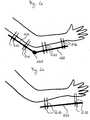
- the wound care kit showncomprises a total of eight stabilizing elements in the form of nails 112 which penetrate the skin of a patient in the forearm and upper arm area and connecting rods 120 which are articulated to one another via a joint 125.
- the connecting rods 120 and the joint 125are exposed outside the patient and form an external fixator that can be used to fix a fracture in the forearm, upper arm and elbow area.
- a film tube 140 made of a water-vapor-permeable material and sealed at one axial end 142is sealed over the arm of the patient and the external fixator.
- the opening 144 of the film tube facing away from the airtightly closed end 142is dimensioned such that the introduction of the patient's extremities into the film tube is not hindered by the external fixator.
- the process of inserting the patient's arm into the film tubeis in the Figures 1b and 1c shown.
- the edge of the film tube surrounding the opening 144is connected to the patient's skin in an air-tight manner by means of adhesive films 150, so that a between the patient's skin and the film tube airtight, but water vapor permeable wound space is created.
- a negative pressurecan be generated in this wound space via a suction connection (not shown), by means of which wound healing is promoted.
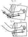
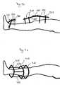
- Embodiment of the invention showndiffers only in that from the Figure 1 Embodiment shown that it has an external fixator with only four nails 210 penetrating the patient's skin and a connecting rod 220.
- the external fixatoris designed to fix a fracture in the area of the wrist.
- the film tube 240which is based on the Figure 2 The embodiment explained is shorter than the film tube 140 which is shown in FIG Figure 1 explained embodiment, since it only has to reach into the elbow area.
- the film tube 240which is hermetically sealed at one axial end 242, is connected hermetically to the patient's skin with the aid of adhesive films 250. This creates a wound space that is sealed airtight but permeable to water vapor and can be evacuated via a suction connection (not shown).
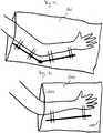
- the embodiment showndiffers essentially from that based on FIG Figures 1 and 2 Embodiment shown that it is designed to treat a wound in the region of a leg.
- the embodiment of the invention shown in FIG. 3comprises a total of six nails 310 penetrating the patient's skin and three connecting rods 320. Two of the nails penetrating the patient's skin are attached in the region of the patient's ankle, a further stabilization aid 325 is provided bridging the ankle. The remaining nails 310 are attached on both sides of the patient's knee joint and are connected to one another via connecting rods 320 which are connected to one another in the region of the knee joint via a joint 325.
- wound care kitan airtightly sealed film tube 340 at an axial end 342, which is dimensioned such that it can be placed with an opening 344 over the leg and the external fixator, as in FIGS Figures 3b and 3c shown.
- an edge surrounding the opening 344can be connected to the patient's skin in an airtight manner by means of adhesive films 350, so as to create an airtight but water vapor-permeable wound space which can be evacuated via a suction connection (not shown).
- the axial length of the film tubeis more than 90 cm.
- the opening circumference length in the area of the opening 344 of the film tubeis more than 120 cm.
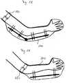
- the embodiment of the invention showndiffers essentially only from that with reference to FIG Figure 3 Embodiment shown that it is intended for treating a wound in the region of a lower leg fracture.
- the external fixator in Figure 4The illustrated embodiment of the invention comprises three stabilization rings 410 which run around the lower leg of the patient and which are fastened to the bone fragments to be connected to one another by means of nails penetrating the patient's skin.
- the circumferential rings 410are connected to one another by means of connecting rods 420.
- a film tube 400which is closed airtightly at an axial end 442, is placed over the lower leg with the external fixator attached to it and connected airtightly to the patient's skin using adhesive films 450.
- the airtight connection to the patient's skincan be adjusted accordingly Figure 4d above the patient's knee joint.
- the wound spacecan be evacuated with the aid of a suction connection, not shown in the drawing, in order to promote wound healing.
- FIG. 5The embodiment of the invention shown differs essentially only from that based on FIG Figure 4 Embodiment shown that the nails penetrating the patient's skin using connecting rods 520 are connected to one another without the use of stabilizing rings.
- filling devices 680 in the shape of a truncated conecan be provided, with which the formation of a cavity between the nails, the film tube and the patient's skin can be prevented.
- the inventionis not limited to the exemplary embodiments explained with reference to the drawing. Rather, with appropriate dimensioning of the film tube, the invention can also be used for negative pressure treatment in the pelvic area, upper arm area, thigh area, etc.
Landscapes
- Health & Medical Sciences (AREA)
- Heart & Thoracic Surgery (AREA)
- Life Sciences & Earth Sciences (AREA)
- Engineering & Computer Science (AREA)
- Biomedical Technology (AREA)
- Animal Behavior & Ethology (AREA)
- General Health & Medical Sciences (AREA)
- Public Health (AREA)
- Veterinary Medicine (AREA)
- Vascular Medicine (AREA)
- Anesthesiology (AREA)
- Hematology (AREA)
- Orthopedic Medicine & Surgery (AREA)
- Surgery (AREA)
- Medical Informatics (AREA)
- Molecular Biology (AREA)
- Nuclear Medicine, Radiotherapy & Molecular Imaging (AREA)
- Epidemiology (AREA)
- Otolaryngology (AREA)
- Surgical Instruments (AREA)
- Materials For Medical Uses (AREA)
- Media Introduction/Drainage Providing Device (AREA)
- Cosmetics (AREA)
Description
Translated fromGermanDie Erfindung betrifft eine Wundversorgungskit nach dem Oberbegriff des Patentanspruchs 1.The invention relates to a wound care kit according to the preamble of claim 1.
Wundversorgungsanordnungen gemäß dem Oberbegriff des Patentanspruchs 1 werden insbesondere im Rahmen der sogenannten Vakuumtherapie eingesetzt. Es hat sich gezeigt, dass im Besonderen die Heilung chronischer Wunden durch Anlegen von Unterdruck an diese Wunden gefördert werden kann. Dabei hat es sich weiter als vorteilhaft erwiesen, wenn die Wunde mit einem offenporigen Schaum oder Gaze als Füllmaterial abgedeckt bzw. gefüllt wird, die Wunde zur Erzeugung eines die Wunde und gegebenenfalls das Füllmaterial enthaltenden abgeschlossenen Wundraums abgedeckt und auf der der Wunde bzw. dem Füllmaterial abgewandten Seite der Abdeckeinrichtung ein Sauganschluss angebracht wird, über den der Wundraum mit einer zum Erzeugen von Unterdruck ausgelegten Saugeinrichtung verbunden werden kann. Bei anderen Anordnungen wird ein Flansch des Sauganschlusses von der Abdeckeinrichtung abgedeckt oder in einer eine Öffnung der Abdeckeinrichtung umlaufenden Tasche aufgenommen. Der Sauganschluss kann beispielsweise mit einem einerseits an einer beispielsweise in Form eines Rohrstutzens ausgeführten Verbindungseinrichtung des Sauganschlusses und andererseits mit einem an eine Saugeinrichtung anschließbaren Schlauch ausgestattet sein. Die Abdeckeinrichtung kann beispielsweise als folienartiges Material ausgeführt sein, welches an die der Wunde benachbarten Hautfläche luftdicht angelegt wird.Wound care arrangements according to the preamble of claim 1 are used in particular in the context of so-called vacuum therapy. It has been shown that in particular the healing of chronic wounds can be promoted by applying negative pressure to these wounds. It has also proven to be advantageous if the wound is covered or filled with an open-pore foam or gauze as the filling material, the wound for producing a closed wound space containing the wound and optionally the filling material and on the wound or the filling material facing away from the cover, a suction port is attached, via which the wound space can be connected to a suction device designed to generate negative pressure. In other arrangements, a flange of the suction connection is covered by the cover device or received in a pocket surrounding an opening of the cover device. The suction connection can be made, for example, with a connection device of the suction connection, for example, on a connection device of the form of a pipe socket and on the other hand be equipped with a hose that can be connected to a suction device. The covering device can be designed, for example, as a film-like material which is applied in an airtight manner to the skin surface adjacent to the wound.
Wundversorgungsanordnungen, die im Rahmen der Vakuumtherapie einsetzbar sind, sind beispielsweise in der
In der
Im Rahmen der Vakuumtherapie einsetzbare Sauganschlüsse, welche über einen Schlauch mit einer Saugeinrichtung verbunden werden können, sind beispielsweise in der
In der
In der
In der
Das Einsatzgebiet bekannter Wundversorgungsanordnungen der eingangs beschriebenen Art ist begrenzt. Angesichts dieser Probleme im Stand der Technik liegt der Erfindung die Aufgabe zugrunde, das Einsatzgebiet von Wundversorgungsanordnungen, die für die Vakuumtherapie geeignet sind, zu erweitern.The field of use of known wound care arrangements of the type described in the introduction is limited. In view of these problems in the prior art, the object of the invention is to expand the field of application of wound care arrangements which are suitable for vacuum therapy.
Erfindungsgemäß wird diese Aufgabe durch ein Wundversorgungskit gemäß Patentanspruch 1 gelöst.According to the invention, this object is achieved by a wound care kit according to claim 1.
Folienschläuche derartiger Wundversorgungskits sind auch dann noch zur Wundversorgung einsetzbar, wenn die Wunde im Bereich eines sogenannten Fixateurs externe liegt. Dabei handelt es sich um ein durch die Haut von außen befestigtes Haltesystem, das dazu dient, einen Teil des Körpers ruhigzustellen. Die Erfindung beruht auf dem Gedanken, dass eine im Bereich eines Fixateur Externe anzulegende Wundversorgungsanordnung ohne Beeinträchtigung der Wundheilung über den gesamten Fixateur Externe gezogen werden kann. Dabei wurde im Rahmen der Erfindung erkannt, dass es für den Erfolg der Vakuumtherapie anders als in der
Als besonders zweckmäßig hat es sich erwiesen, wenn der Folienschlauch kreiszylindermantel- oder kegelstumpfmantelförmig ausgelegt ist, d.h. in einer Axialschnittebene rechteck- oder trapezförmig ausgeführt ist. Zusätzlich oder alternativ kann der Folienschlauch an einem axialen Ende an die Form eines Arms oder eines Beins angepasst sein. Er kann dann ohne weiteres mit der überdimensionierten Öffnung über beliebige Extremitäten gezogen werden, an die ein Fixateur Externe angelegt sein kann. Im Bereich der überdimensionierten Öffnung kann die Abdeckeinrichtung anschließend mit geeignetem Haftstreifen an der Haut dichtend befestigt werden. In diesem Zusammenhang wird Bezug genommen auf den Offenbarungsgehalt der
Dem Folienschlauch eines erfindungsgemäßen Wundversorgungskits kann eine Applikationshilfe wie etwa ein stabiler Ring mit einem an die Öffnungsumfangslänge angepassten Umfang oder ein Netz zugeordnet sein. Im Besonderen bei Einsatz einer Applikationshilfe in Form eines stabilen Rings kann die gewünschte Öffnungsumfangslänge auch durch Dehnen eines zur Herstellung des Folienschlauchs eingesetzten dehnbaren Materials, wie etwa eines Parafilms, erreicht werden.An application aid such as a stable ring with a circumference adapted to the circumference of the opening or a net can be assigned to the film tube of a wound care kit according to the invention. In particular when using an application aid in the form of a stable ring, the desired circumferential opening length can also be achieved by stretching an expandable material, such as a parafilm, used to manufacture the film tube.
Ein erfindungsgemäßes Wundversorgungskit ist besonders variabel zur Versorgung von Wunden im Bereich unterschiedlicher Extremitäten, die mit einem Fixateur Externe versorgt sind, anlegbar, wenn ein Folienschlauch ggf. geringer Dehnbarkeit über eine axiale Länge von 40 cm oder mehr, insbesondere 50 cm oder mehr, besonders bevorzugt 75 cm oder mehr eine Umfangslänge, d.h. eine Länge in einer senkrecht zur Achse verlaufenden Ebene, von 70 cm oder mehr, insbesondere 100 cm oder mehr aufweist.A wound care kit according to the invention can be applied in a particularly variable manner for the care of wounds in the region of different extremities, which are supplied with an external fixator, if a film tube, possibly with little stretchability, is particularly preferred over an axial length of 40 cm or more, in particular 50 cm or more 75 cm or more a circumferential length, ie has a length in a plane perpendicular to the axis of 70 cm or more, in particular 100 cm or more.
Im Rahmen der Erfindung hat es sich weiter als zweckmäßig erwiesen, wenn der Folienschlauch eines erfindungsgemäßen Wundversorgungskits bei der Applikation in Abhängigkeit von den anatomischen Gegebenheiten konfektioniert wird. In diesem Zusammenhang ist es zweckmäßig, wenn der Folienschlauch mit einer sichtbaren Markierung, wie etwa einer das Anpassen an den Wundraum erleichternden und die axiale Länge entsprechender Folienschlauchabschnitte angebenden Längenmarkierungen ausgestattet ist.In the context of the invention, it has also proven to be expedient if the film tube of a wound care kit according to the invention is assembled during application depending on the anatomical conditions. In this context, it is expedient if the film tube has a visible marking, such as one which facilitates the adaptation to the wound space and the axial length the corresponding length of film tube sections is equipped.
Die bei der Behandlung mit Hilfe eines Fixateur Externe häufig beobachtete "Pin-Track-Infektion", d.h. eine Infektion der Weichteile um die Pinstellen, d.h. die Stellen, an denen das Haltesytem die Haut durchdringt, kann vermieden werden, wenn der Abdeckrichtung eine Fülleinrichtung zum Füllen eines bei Erzeugen eines Unterdrucks zwischen der Abdeckeinrichtung und der Haut des Patienten zwischen der Haut des Patienten, der Abdeckeinrichtung und einer die Haut des Patienten durchdringenden Stabilisierungseinrichtung entstehenden Hohlraums zugeordnet ist. So kann in dem gesamten Wundraum, einschließlich der Pinstelle, ein die Wundheilung fördernder Unterdruck aufrechterhalten werden.The "pin-track infection" frequently observed during treatment with the help of an external fixator, infection of the soft tissues around the pin sites, i.e. the locations at which the holding system penetrates the skin can be avoided if the covering device has a filling device for filling between the patient's skin, the covering device and a patient's skin when a negative pressure is generated between the covering device and the patient's skin Stabilizing device emerging cavity is assigned. In this way, a negative pressure promoting wound healing can be maintained in the entire wound area, including the pin site.
Die Fülleinrichtung kann die Haut des Patienten durchdringende Stangen des Fixateur Externe umlaufen, wobei eine äußere Begrenzungsfläche der Fülleinrichtung kegelstumpfförmig ausgeführt sein kann. So kann die Fülleinrichtung einen das Einführen der Stangen des Fixateur Externe in einen die Fülleinrichtung axial durchsetzenden Hohlraum erleichternden Schlitz in einer Axialebene der Fülleinrichtung aufweisen.The filling device can run around the patient's skin-penetrating rods of the external fixator, wherein an outer boundary surface of the filling device can be frustoconical. For example, the filling device can have a slot in an axial plane of the filling device that facilitates the insertion of the rods of the external fixator into a cavity that axially penetrates the filling device.
Alternativ oder zusätzlich zu Fülleinrichtungen mit kegelstumpfmantelförmiger Begrenzungsfläche können Fülleinrichtungen in Form von verformbarer Gaze zum Einsatz kommen.As an alternative or in addition to filling devices with a frustoconical boundary surface, filling devices in the form of deformable gauze can be used.
Zweckmäßigerweise ist der Folienschlauch eines erfindungsgemäßen Wundversorgungskits gegebenenfalls zusammen mit der Fülleinrichtung in einer sterilen bzw. sterilisierbaren Packung aufgenommen. Der Wundversorgungsschlauch kann dann in sterilem Zustand gelagert und eingesetzt werden. In diesem Zusammenhang hat es sich als besonders zweckmäßig erwiesen, wenn der Schlauch so in der Packung aufgenommen ist, dass die Entnahme des Schlauchs aus der Packung keine Probleme bereitet. Dazu kann der Folienschlauch in der sterilen Packung in geraffter Form oder auf einem Träger, wie etwa einem Kartonträger, in gewickelter Form aufgenommen sein. In der sterilen Packung können weitere Applikationshilfen wie Fäden, Ohren (Entnahme- bzw. Applikationshilfe) oder ähnliches enthalten sein. In diesem Zusammenhang ist beispielsweise daran gedacht, den Folienschlauch mit zusätzlichen "Ohren" zu versehen, an denen der Folienschlauch ohne Gefahr von Beschädigung angefasst und entnommen werden kann.The film tube of a wound care kit according to the invention is expediently accommodated together with the filling device in a sterile or sterilizable package. The wound care tube can then be stored and used in a sterile condition. In this connection, it has proven to be particularly expedient if the hose is accommodated in the package in such a way that the hose is not problematic to remove from the package. For this purpose, the film tube can be accommodated in the sterile package in a gathered form or on a carrier, such as a cardboard carrier, in a wound form. Further application aids such as threads, ears (removal or application aid) or the like can be contained in the sterile package. In this context, it is contemplated, for example, to provide the film tube with additional "ears" on which the film tube can be gripped and removed without risk of damage.
Zur Vermeidung von Beschädigungen des Folienschlauchs bei der Applikation und/oder während der Unterdrucktherapie ist es zweckmäßig, wenn der Folienschlauch gegebenenfalls durch separate Verstärkungsstreifen herstellbare Kontaktbereiche erhöhter Reißfestigkeit aufweist. Diese Kontaktbereiche können ohne Gefahr einer Beschädigung in Anlage an die außerhalb des Patienten freiliegenden Stabilisierungselemente des Fixateur Externe gelangen.To avoid damage to the film tube during application and / or during negative pressure therapy, it is expedient if the film tube has contact areas which can be produced by separate reinforcement strips and which have increased tear resistance. These contact areas can come into contact with the stabilizing elements of the external fixator exposed outside the patient without risk of damage.
Ein erfindungsgemäßes Wundversorgungskit weist demnach eine Wundversorgungsanordnung sowie einen Fixateur Externe mit einem bei der Behandlung eines Patienten zumindest teilweise außerhalb des Patienten freiliegenden Stabilisierungselement auf, wobei der Folienschlauch der Wundversorgungsanordnung so dimensioniert ist, dass er den Fixateur Externe bei der Behandlung des Patienten vollständig aufnehmen kann.A wound care kit according to the invention accordingly has a wound care arrangement and an external fixator with a stabilization element which is at least partially exposed outside the patient when treating a patient, the film tube of the wound care arrangement being dimensioned such that it can completely accommodate the external fixator when treating the patient.
Wenn beispielsweise ein Fixateur Externe zum Stabilisieren eines Unterarmbruchs eingesetzt wird und die Haut des Patienten durchdringende Stangen aufweist, die außerhalb des Patienten mit Hilfe einer Verbindungsstange gegebenenfalls variabler Länge verbunden werden, ist der Folienschlauch eines erfindungsgemäßen Wundversorgungskits so zu dimensionieren, dass er nicht nur den Unterarm des Patienten, sondern auch die den Unterarm durchdringenden Stangen und die Verbindungsstangen aufnehmen kann, so dass ein Unterdruck innerhalb des zwischen der Haut des Patienten und dem Folienschlauch gebildeten und den Fixateur Externe enthaltenden Raum erzeugt werden kann.If, for example, an external fixator is used to stabilize a forearm fracture and the patient's skin has penetrating rods that are connected outside of the patient with the help of a connecting rod, which may be of variable length, the film tube of a wound care kit according to the invention must be dimensioned such that it does not only cover the forearm of the patient, but also the rods penetrating the forearm and the connecting rods, so that a negative pressure can be generated within the space formed between the patient's skin and the film tube and containing the external fixator.
Ähnlich ist der Folienschlauch eines erfindungsgemäßen Wundversorgungskits zu dimensionieren, wenn der Fixateur Externe zum Fixieren eines Unter- oder Oberschenkelbruchs, eines Beckenbruchs, eines Handbruchs, eines Fußbruchs oder dergleichen eingesetzt wird. In jedem Fall ist dafür Sorge zu tragen, dass der Folienschlauch nicht nur das zu behandelnde Körperteil, sondern auch den entsprechenden Fixateur Externe bei der Behandlung aufnehmen kann.Similarly, the film tube of a wound care kit according to the invention is to be dimensioned if the external fixator is used to fix a lower or upper leg fracture, a pelvic fracture, a broken hand, a broken foot or the like. In any case, care must be taken to ensure that the film tube can accommodate not only the part of the body to be treated, but also the corresponding external fixator during the treatment.
Ein erfindungsgemäßes Wundversorgungskit kann Stabilisierungselemente in Form von Nägeln, Stiften oder dergleichen aufweisen. Zur Vermeidung einer Beschädigung des Folienschlauchs während Transport und Lagerung eines erfindungsgemäßen Wundversorgungskits können den Nägeln, Stiften, Schrauben oder dergleichen Abdeckungen oder Polsterungen zugeordnet sein. Dabei ist bei einer Ausführungsform der Erfindung daran gedacht, dass die Stabilisierungseinrichtung insgesamt durch eine Abdeckung oder Polsterung von dem Folienschlauch getrennt gehalten wird. Alternativ ist auch an solche Ausführungsformen gedacht, bei denen jedem einzelnen Stabilisierungselement, wie etwa jeder einzelnen Schraube, jedem einzelnen Nagel oder dergleichen eine einzelne Abdeckung bzw. Polsterung zugeordnet ist. Für den Fall, dass trotz der beschriebenen Maßnahmen Beschädigungen des Folienschlauchs auftreten, ist bei einer besonders bevorzugten Ausführungsform der Erfindung daran gedacht, dass das Wundversorgungskit neben den Stabilisierungselementen, dem Folienschlauch und gegebenenfalls den Fülleinrichtungen auch Reparaturmittel, wie etwa Spraypflaster, eine Gelmasse oder dergleichen zum Abdichten undichter Stellen in dem Folienschlauch aufweist. Die beschriebenen Fülleinrichtungen können auch in Form einer Gelmasse, wie etwa eines Wundsilikons, oder eines Füllkegels in dem Wundversorgungskit bereitgestellt werden.A wound care kit according to the invention can have stabilizing elements in the form of nails, pins or the like. To avoid damage to the film tube during transport and storage of a wound care kit according to the invention, the nails, pins, screws or the like can be assigned covers or upholstery. In one embodiment of the invention, the stabilizing device is covered by a cover or padding is kept separate from the film tube. As an alternative, such embodiments are also envisaged in which each individual stabilizing element, such as each individual screw, each individual nail or the like, is assigned an individual covering or padding. In the event that, despite the measures described, damage to the film tube occurs, in a particularly preferred embodiment of the invention it is contemplated that the wound care kit, in addition to the stabilizing elements, the film tube and possibly the filling devices, also include repair agents such as spray plasters, a gel mass or the like Sealing leaks in the film tube. The filling devices described can also be provided in the form of a gel mass, such as a wound silicone, or a filling cone in the wound care kit.
Nachstehend wird die Erfindung unter Bezugnahme auf die Zeichnung, auf die hinsichtlich aller erfindungswesentlichen und in der Beschreibung nicht näher herausgestellten Einzelheiten ausdrücklich verwiesen wird, erläutert. In der Zeichnung zeigt:
Fig. 1 ein Wundversorgungskit gemäß einer ersten Ausführungsform der Erfindung,Fig. 2 ein Wundversorgungskit gemäß einer zweiten Ausführungsform der Erfindung,Fig. 3 ein Wundversorgungskit gemäß einer dritten Ausführungsform der Erfindung,Fig. 4 ein Wundversorgungskit gemäß einer vierten Ausführungsform der Erfindung,Fig. 5 ein Wundversorgungskit gemäß einer fünften Ausführungsform der Erfindung, undFig. 6 ein Wundversorgungskit gemäß einer sechsten Ausführungsform der Erfindung.
Fig. 1 a wound care kit according to a first embodiment of the invention,Fig. 2 a wound care kit according to a second embodiment of the invention,Fig. 3 a wound care kit according to a third embodiment of the invention,Fig. 4 a wound care kit according to a fourth embodiment of the invention,Fig. 5 a wound care kit according to a fifth embodiment of the invention, andFig. 6 a wound care kit according to a sixth embodiment of the invention.
Das in
Die in
Die in
Die in
Die in
Die Erfindung ist nicht auf die anhand der Zeichnung erläuterten Ausführungsbeispiele beschränkt. Vielmehr kann die Erfindung bei entsprechender Dimensionierung des Folienschlauchs auch zur Unterdruckbehandlung im Beckenbereich, Oberarmbereich, Oberschenkelbereich usw. eingesetzt werden.The invention is not limited to the exemplary embodiments explained with reference to the drawing. Rather, with appropriate dimensioning of the film tube, the invention can also be used for negative pressure treatment in the pelvic area, upper arm area, thigh area, etc.
Claims (12)
- A wound care system comprising
a wound care arrangement with a means of covering which can be fixed to the skin surrounding the wound and creates an enclosed wound space containing the wound, with said covering having a tubular film and portions at least of the covering being water vapour-permeable, and with a suction connection by means of which a vacuum can be created in the wound space, wherein the tubular film has an opening with an opening circumference length of 80 cm or more, in particular 130 cm or more, and
an external fixator having at least one stabilising element which is at least partially exposed outside of a patient during treatment of the patient, wherein the tubular film is dimensioned to fully enclose the external fixator during treatment of the patient. - The wound care system according to claim 1,characterised by a repair means, such as a spray plaster, gel compound or similar for sealing leaks in the tubular film.
- The wound care system according to claim 1 or 2,characterised by a filling device, such as a gel compound, in particular wound silicon, and/or at least a cone surrounding a stabilising element.
- The wound care system according to one of the preceding claims,characterised in that the tubular film is designed as a sleeve with a circular cylinder shape or truncated cone shape.
- The wound care system according to one of claims 1 to 3,characterised in that the tubular film is adapted to the shape of an arm or leg.
- The wound care system according to one of the preceding claims,characterised in that an application aid, such as a ring adapted to the opening circumference length, or a mesh, is associated with the tubular film.
- The wound care system according to one of the preceding claims,characterised in that the tubular film has a circumference length of 70 cm or more, in particular 100 cm or more over an axial length of 40 cm or more, in particular 50 cm or more, particularly preferably 75 cm or more.
- The wound care system according to one of the preceding claims,characterised in that the tubular film has a visible marking, such as a length marking indicating the axial length and facilitating adaptation to the wound space.
- The wound care system according to one of the preceding claims,characterised in that a filling device for filling a cavity created in the wound space between the skin of the patient, the covering and a stabilising device penetrating the skin of the patient when a vacuum is produced is associated with the covering.
- The wound care system according to one of the preceding claims,characterised in that the tubular film is sterilely packaged, optionally together with the filling device.
- The wound care system according to claim 10,characterised in that the tubular film is sterilely packaged in a gathered-up state or wound onto a carrier, such as a cardboard carrier.
- The wound care system according to one of the preceding claims,characterised in that the tubular film may have contact areas with increased tear resistance optionally created by separate stiffening strips.
Priority Applications (7)
| Application Number | Priority Date | Filing Date | Title |
|---|---|---|---|
| EP15002171.5AEP3120817B1 (en) | 2015-07-22 | 2015-07-22 | Wound treatment assembly |
| MX2016009543AMX387499B (en) | 2015-07-22 | 2016-07-21 | WOUND TREATMENT ASSEMBLY. |
| RU2016130022ARU2720104C2 (en) | 2015-07-22 | 2016-07-22 | Wound dressing kit |
| CN201610581999.2ACN106361497A (en) | 2015-07-22 | 2016-07-22 | Wound care device |
| US15/216,857US20170043067A1 (en) | 2015-07-22 | 2016-07-22 | Wound care device |
| CA2936919ACA2936919A1 (en) | 2015-07-22 | 2016-07-22 | Wound care device |
| AU2016206362AAU2016206362B2 (en) | 2015-07-22 | 2016-07-22 | Wound care device |
Applications Claiming Priority (1)
| Application Number | Priority Date | Filing Date | Title |
|---|---|---|---|
| EP15002171.5AEP3120817B1 (en) | 2015-07-22 | 2015-07-22 | Wound treatment assembly |
Publications (2)
| Publication Number | Publication Date |
|---|---|
| EP3120817A1 EP3120817A1 (en) | 2017-01-25 |
| EP3120817B1true EP3120817B1 (en) | 2020-07-01 |
Family
ID=53719597
Family Applications (1)
| Application Number | Title | Priority Date | Filing Date |
|---|---|---|---|
| EP15002171.5AActiveEP3120817B1 (en) | 2015-07-22 | 2015-07-22 | Wound treatment assembly |
Country Status (7)
| Country | Link |
|---|---|
| US (1) | US20170043067A1 (en) |
| EP (1) | EP3120817B1 (en) |
| CN (1) | CN106361497A (en) |
| AU (1) | AU2016206362B2 (en) |
| CA (1) | CA2936919A1 (en) |
| MX (1) | MX387499B (en) |
| RU (1) | RU2720104C2 (en) |
Families Citing this family (3)
| Publication number | Priority date | Publication date | Assignee | Title |
|---|---|---|---|---|
| CN107397983A (en)* | 2017-08-29 | 2017-11-28 | 浙江保尔曼生物科技有限公司 | Wound healing and bone regeneration instrument |
| CN112914911A (en)* | 2021-02-25 | 2021-06-08 | 李斌斌 | Infectious diseases branch of academic or vocational study is with wound nursing device |
| CN115844618B (en)* | 2023-03-01 | 2023-05-09 | 吉林大学 | Limb restraint device for PICC (peripherally inserted central catheter) |
Family Cites Families (19)
| Publication number | Priority date | Publication date | Assignee | Title |
|---|---|---|---|---|
| US4846164A (en)* | 1987-08-07 | 1989-07-11 | Martz Joel D | Vapor permeable dressing |
| GB2265314B (en)* | 1989-11-29 | 1994-05-18 | South Glamorgan Health Authori | Protective articles. |
| US5645081A (en) | 1991-11-14 | 1997-07-08 | Wake Forest University | Method of treating tissue damage and apparatus for same |
| GB9523253D0 (en) | 1995-11-14 | 1996-01-17 | Mediscus Prod Ltd | Portable wound treatment apparatus |
| GB9719520D0 (en) | 1997-09-12 | 1997-11-19 | Kci Medical Ltd | Surgical drape and suction heads for wound treatment |
| US6152925A (en)* | 1998-03-04 | 2000-11-28 | University Of Iowa Research Foundation | Method and apparatus for external fixation of an elbow |
| MXPA01007589A (en) | 1999-01-26 | 2003-06-24 | Ark Therapeutics Ltd | Protective cover for injured limbs. |
| EP1487389B1 (en) | 2002-02-28 | 2011-10-05 | KCI Medical Resources | External catheter access to vacuum bandage |
| GB0712735D0 (en) | 2006-07-26 | 2007-08-08 | Smith & Nephew | Dressing |
| US7931651B2 (en)* | 2006-11-17 | 2011-04-26 | Wake Lake University Health Sciences | External fixation assembly and method of use |
| WO2009124548A1 (en) | 2008-04-11 | 2009-10-15 | Coloplast A/S | Wound cover device |
| KR20100007548A (en) | 2008-07-14 | 2010-01-22 | 주식회사 바이오알파 | Medical suction head |
| WO2010011148A1 (en) | 2008-07-24 | 2010-01-28 | Frederick George | Negative pressure wound therapy system |
| DE102009019646B4 (en) | 2009-04-30 | 2015-04-30 | Lohmann & Rauscher Gmbh | Wound covering and method of manufacture |
| DE102010034819A1 (en)* | 2010-08-19 | 2012-02-23 | Paul Hartmann Ag | Use of a polyurethane foam as wound dressing in negative pressure therapy |
| WO2012083935A1 (en)* | 2010-12-23 | 2012-06-28 | Alfons Erdmann | Device for suctioning a fluid from a cover of a body part |
| DE102012205408A1 (en)* | 2011-04-09 | 2012-10-11 | Klaus Junig | Device for squeezing out tissue fluid of leg for treatment of edema, has pump in fluid communication with interior of sleeve, and control unit for alternately controlling pump and valve that is in fluid communication with sleeve interior |
| EP2636417B1 (en) | 2012-03-05 | 2017-04-26 | Lohmann & Rauscher GmbH | Wound treatment assembly and covering device for same |
| EP2852419B1 (en)* | 2012-05-22 | 2019-11-20 | Smith & Nephew plc | Wound closure device |
- 2015
- 2015-07-22EPEP15002171.5Apatent/EP3120817B1/enactiveActive
- 2016
- 2016-07-21MXMX2016009543Apatent/MX387499B/enunknown
- 2016-07-22USUS15/216,857patent/US20170043067A1/ennot_activeAbandoned
- 2016-07-22CNCN201610581999.2Apatent/CN106361497A/enactivePending
- 2016-07-22AUAU2016206362Apatent/AU2016206362B2/enactiveActive
- 2016-07-22RURU2016130022Apatent/RU2720104C2/enactive
- 2016-07-22CACA2936919Apatent/CA2936919A1/enactivePending
Non-Patent Citations (1)
| Title |
|---|
| None* |
Also Published As
| Publication number | Publication date |
|---|---|
| MX2016009543A (en) | 2017-07-24 |
| RU2016130022A (en) | 2018-01-25 |
| AU2016206362B2 (en) | 2020-11-05 |
| US20170043067A1 (en) | 2017-02-16 |
| AU2016206362A1 (en) | 2017-02-09 |
| RU2720104C2 (en) | 2020-04-24 |
| EP3120817A1 (en) | 2017-01-25 |
| MX387499B (en) | 2025-03-18 |
| CA2936919A1 (en) | 2017-01-22 |
| CN106361497A (en) | 2017-02-01 |
Similar Documents
| Publication | Publication Date | Title |
|---|---|---|
| EP2822613B1 (en) | Wound treatment assembly and covering device for same | |
| EP0734229B1 (en) | Device for stimulating the formation of new tissues in extensive and deep wounds | |
| DE69825767T2 (en) | SUCTION HEAD FOR WOUND TREATMENT AND COMBINATION WITH A SURGICAL COVER | |
| EP2968021B1 (en) | Finger-stall | |
| EP3117806A1 (en) | Wound treatment assembly | |
| EP2858613B1 (en) | Medicinal product for the care of an individual | |
| DE69220339T2 (en) | Rope-like wound dressing | |
| EP3120817B1 (en) | Wound treatment assembly | |
| EP2335661B1 (en) | Cutting aid for wound dressing for suppression therapy | |
| EP3400920B1 (en) | Dressing for treating a wound | |
| DE102014216139A1 (en) | Wound dressing kit for the treatment of wound cavities | |
| EP1603498A1 (en) | Device for the analgesic immobilisation of broken ribs | |
| DE202010012324U1 (en) | Suction device for wound treatment | |
| WO2004112666A1 (en) | Dressing | |
| DE202019003243U1 (en) | Optic patches | |
| EP4491165A1 (en) | Wound dressing with a tamponade unit and use of a wound dressing | |
| DE102011106540A1 (en) | Gas-tight cover for pipe used in medical field, has sleeve portion designed as prism with three lateral surfaces that adjoin one another at acute angles in cross-section of prism | |
| DE202012010235U1 (en) | Orthopedic aid | |
| EP4275661A1 (en) | Splint device and system comprising such a splint | |
| EP1466566A1 (en) | Infection prevention device for transcutaneous implants | |
| DE102020113639A1 (en) | Device for receiving a limb stump of a patient | |
| DE202015104246U1 (en) | Finger film dressing | |
| DE202016104332U1 (en) | Finger film dressing | |
| DE202014010037U1 (en) | Device for the removal of wound secretions from body cavities and wounds | |
| HK1228244A1 (en) | Wound care arrangement |
Legal Events
| Date | Code | Title | Description |
|---|---|---|---|
| PUAI | Public reference made under article 153(3) epc to a published international application that has entered the european phase | Free format text:ORIGINAL CODE: 0009012 | |
| STAA | Information on the status of an ep patent application or granted ep patent | Free format text:STATUS: REQUEST FOR EXAMINATION WAS MADE | |
| 17P | Request for examination filed | Effective date:20150722 | |
| AK | Designated contracting states | Kind code of ref document:A1 Designated state(s):AL AT BE BG CH CY CZ DE DK EE ES FI FR GB GR HR HU IE IS IT LI LT LU LV MC MK MT NL NO PL PT RO RS SE SI SK SM TR | |
| AX | Request for extension of the european patent | Extension state:BA ME | |
| RIC1 | Information provided on ipc code assigned before grant | Ipc:A61F 13/00 20060101ALI20191218BHEP Ipc:A61F 17/00 20060101ALI20191218BHEP Ipc:A61F 13/02 20060101ALI20191218BHEP Ipc:A61F 13/06 20060101ALI20191218BHEP Ipc:A61F 15/00 20060101AFI20191218BHEP Ipc:A61F 13/08 20060101ALI20191218BHEP Ipc:A61M 1/00 20060101ALI20191218BHEP Ipc:A61F 13/10 20060101ALI20191218BHEP | |
| GRAP | Despatch of communication of intention to grant a patent | Free format text:ORIGINAL CODE: EPIDOSNIGR1 | |
| STAA | Information on the status of an ep patent application or granted ep patent | Free format text:STATUS: GRANT OF PATENT IS INTENDED | |
| INTG | Intention to grant announced | Effective date:20200131 | |
| GRAS | Grant fee paid | Free format text:ORIGINAL CODE: EPIDOSNIGR3 | |
| GRAA | (expected) grant | Free format text:ORIGINAL CODE: 0009210 | |
| STAA | Information on the status of an ep patent application or granted ep patent | Free format text:STATUS: THE PATENT HAS BEEN GRANTED | |
| AK | Designated contracting states | Kind code of ref document:B1 Designated state(s):AL AT BE BG CH CY CZ DE DK EE ES FI FR GB GR HR HU IE IS IT LI LT LU LV MC MK MT NL NO PL PT RO RS SE SI SK SM TR | |
| REG | Reference to a national code | Ref country code:CH Ref legal event code:EP Ref country code:CH Ref legal event code:NV Representative=s name:E. BLUM AND CO. AG PATENT- UND MARKENANWAELTE , CH Ref country code:AT Ref legal event code:REF Ref document number:1285454 Country of ref document:AT Kind code of ref document:T Effective date:20200715 | |
| REG | Reference to a national code | Ref country code:IE Ref legal event code:FG4D Free format text:LANGUAGE OF EP DOCUMENT: GERMAN | |
| REG | Reference to a national code | Ref country code:DE Ref legal event code:R096 Ref document number:502015012889 Country of ref document:DE | |
| REG | Reference to a national code | Ref country code:NL Ref legal event code:FP | |
| REG | Reference to a national code | Ref country code:LT Ref legal event code:MG4D | |
| PG25 | Lapsed in a contracting state [announced via postgrant information from national office to epo] | Ref country code:BG Free format text:LAPSE BECAUSE OF FAILURE TO SUBMIT A TRANSLATION OF THE DESCRIPTION OR TO PAY THE FEE WITHIN THE PRESCRIBED TIME-LIMIT Effective date:20201001 | |
| PG25 | Lapsed in a contracting state [announced via postgrant information from national office to epo] | Ref country code:PT Free format text:LAPSE BECAUSE OF FAILURE TO SUBMIT A TRANSLATION OF THE DESCRIPTION OR TO PAY THE FEE WITHIN THE PRESCRIBED TIME-LIMIT Effective date:20201102 Ref country code:FI Free format text:LAPSE BECAUSE OF FAILURE TO SUBMIT A TRANSLATION OF THE DESCRIPTION OR TO PAY THE FEE WITHIN THE PRESCRIBED TIME-LIMIT Effective date:20200701 Ref country code:LT Free format text:LAPSE BECAUSE OF FAILURE TO SUBMIT A TRANSLATION OF THE DESCRIPTION OR TO PAY THE FEE WITHIN THE PRESCRIBED TIME-LIMIT Effective date:20200701 Ref country code:GR Free format text:LAPSE BECAUSE OF FAILURE TO SUBMIT A TRANSLATION OF THE DESCRIPTION OR TO PAY THE FEE WITHIN THE PRESCRIBED TIME-LIMIT Effective date:20201002 Ref country code:NO Free format text:LAPSE BECAUSE OF FAILURE TO SUBMIT A TRANSLATION OF THE DESCRIPTION OR TO PAY THE FEE WITHIN THE PRESCRIBED TIME-LIMIT Effective date:20201001 Ref country code:ES Free format text:LAPSE BECAUSE OF FAILURE TO SUBMIT A TRANSLATION OF THE DESCRIPTION OR TO PAY THE FEE WITHIN THE PRESCRIBED TIME-LIMIT Effective date:20200701 Ref country code:CZ Free format text:LAPSE BECAUSE OF FAILURE TO SUBMIT A TRANSLATION OF THE DESCRIPTION OR TO PAY THE FEE WITHIN THE PRESCRIBED TIME-LIMIT Effective date:20200701 Ref country code:SE Free format text:LAPSE BECAUSE OF FAILURE TO SUBMIT A TRANSLATION OF THE DESCRIPTION OR TO PAY THE FEE WITHIN THE PRESCRIBED TIME-LIMIT Effective date:20200701 Ref country code:HR Free format text:LAPSE BECAUSE OF FAILURE TO SUBMIT A TRANSLATION OF THE DESCRIPTION OR TO PAY THE FEE WITHIN THE PRESCRIBED TIME-LIMIT Effective date:20200701 | |
| PG25 | Lapsed in a contracting state [announced via postgrant information from national office to epo] | Ref country code:PL Free format text:LAPSE BECAUSE OF FAILURE TO SUBMIT A TRANSLATION OF THE DESCRIPTION OR TO PAY THE FEE WITHIN THE PRESCRIBED TIME-LIMIT Effective date:20200701 Ref country code:RS Free format text:LAPSE BECAUSE OF FAILURE TO SUBMIT A TRANSLATION OF THE DESCRIPTION OR TO PAY THE FEE WITHIN THE PRESCRIBED TIME-LIMIT Effective date:20200701 Ref country code:LV Free format text:LAPSE BECAUSE OF FAILURE TO SUBMIT A TRANSLATION OF THE DESCRIPTION OR TO PAY THE FEE WITHIN THE PRESCRIBED TIME-LIMIT Effective date:20200701 Ref country code:IS Free format text:LAPSE BECAUSE OF FAILURE TO SUBMIT A TRANSLATION OF THE DESCRIPTION OR TO PAY THE FEE WITHIN THE PRESCRIBED TIME-LIMIT Effective date:20201101 | |
| PG25 | Lapsed in a contracting state [announced via postgrant information from national office to epo] | Ref country code:MC Free format text:LAPSE BECAUSE OF FAILURE TO SUBMIT A TRANSLATION OF THE DESCRIPTION OR TO PAY THE FEE WITHIN THE PRESCRIBED TIME-LIMIT Effective date:20200701 | |
| REG | Reference to a national code | Ref country code:DE Ref legal event code:R097 Ref document number:502015012889 Country of ref document:DE | |
| PG25 | Lapsed in a contracting state [announced via postgrant information from national office to epo] | Ref country code:DK Free format text:LAPSE BECAUSE OF FAILURE TO SUBMIT A TRANSLATION OF THE DESCRIPTION OR TO PAY THE FEE WITHIN THE PRESCRIBED TIME-LIMIT Effective date:20200701 Ref country code:EE Free format text:LAPSE BECAUSE OF FAILURE TO SUBMIT A TRANSLATION OF THE DESCRIPTION OR TO PAY THE FEE WITHIN THE PRESCRIBED TIME-LIMIT Effective date:20200701 Ref country code:RO Free format text:LAPSE BECAUSE OF FAILURE TO SUBMIT A TRANSLATION OF THE DESCRIPTION OR TO PAY THE FEE WITHIN THE PRESCRIBED TIME-LIMIT Effective date:20200701 Ref country code:SM Free format text:LAPSE BECAUSE OF FAILURE TO SUBMIT A TRANSLATION OF THE DESCRIPTION OR TO PAY THE FEE WITHIN THE PRESCRIBED TIME-LIMIT Effective date:20200701 Ref country code:LU Free format text:LAPSE BECAUSE OF NON-PAYMENT OF DUE FEES Effective date:20200722 | |
| PLBE | No opposition filed within time limit | Free format text:ORIGINAL CODE: 0009261 | |
| STAA | Information on the status of an ep patent application or granted ep patent | Free format text:STATUS: NO OPPOSITION FILED WITHIN TIME LIMIT | |
| PG25 | Lapsed in a contracting state [announced via postgrant information from national office to epo] | Ref country code:AL Free format text:LAPSE BECAUSE OF FAILURE TO SUBMIT A TRANSLATION OF THE DESCRIPTION OR TO PAY THE FEE WITHIN THE PRESCRIBED TIME-LIMIT Effective date:20200701 | |
| 26N | No opposition filed | Effective date:20210406 | |
| PG25 | Lapsed in a contracting state [announced via postgrant information from national office to epo] | Ref country code:SK Free format text:LAPSE BECAUSE OF FAILURE TO SUBMIT A TRANSLATION OF THE DESCRIPTION OR TO PAY THE FEE WITHIN THE PRESCRIBED TIME-LIMIT Effective date:20200701 | |
| PG25 | Lapsed in a contracting state [announced via postgrant information from national office to epo] | Ref country code:IE Free format text:LAPSE BECAUSE OF NON-PAYMENT OF DUE FEES Effective date:20200722 Ref country code:SI Free format text:LAPSE BECAUSE OF FAILURE TO SUBMIT A TRANSLATION OF THE DESCRIPTION OR TO PAY THE FEE WITHIN THE PRESCRIBED TIME-LIMIT Effective date:20200701 | |
| PG25 | Lapsed in a contracting state [announced via postgrant information from national office to epo] | Ref country code:TR Free format text:LAPSE BECAUSE OF FAILURE TO SUBMIT A TRANSLATION OF THE DESCRIPTION OR TO PAY THE FEE WITHIN THE PRESCRIBED TIME-LIMIT Effective date:20200701 Ref country code:MT Free format text:LAPSE BECAUSE OF FAILURE TO SUBMIT A TRANSLATION OF THE DESCRIPTION OR TO PAY THE FEE WITHIN THE PRESCRIBED TIME-LIMIT Effective date:20200701 Ref country code:CY Free format text:LAPSE BECAUSE OF FAILURE TO SUBMIT A TRANSLATION OF THE DESCRIPTION OR TO PAY THE FEE WITHIN THE PRESCRIBED TIME-LIMIT Effective date:20200701 | |
| PG25 | Lapsed in a contracting state [announced via postgrant information from national office to epo] | Ref country code:MK Free format text:LAPSE BECAUSE OF FAILURE TO SUBMIT A TRANSLATION OF THE DESCRIPTION OR TO PAY THE FEE WITHIN THE PRESCRIBED TIME-LIMIT Effective date:20200701 | |
| PGFP | Annual fee paid to national office [announced via postgrant information from national office to epo] | Ref country code:NL Payment date:20220822 Year of fee payment:8 | |
| PGFP | Annual fee paid to national office [announced via postgrant information from national office to epo] | Ref country code:BE Payment date:20220822 Year of fee payment:8 | |
| P01 | Opt-out of the competence of the unified patent court (upc) registered | Effective date:20230516 | |
| REG | Reference to a national code | Ref country code:NL Ref legal event code:MM Effective date:20230801 | |
| REG | Reference to a national code | Ref country code:BE Ref legal event code:MM Effective date:20230731 | |
| PG25 | Lapsed in a contracting state [announced via postgrant information from national office to epo] | Ref country code:NL Free format text:LAPSE BECAUSE OF NON-PAYMENT OF DUE FEES Effective date:20230801 | |
| PG25 | Lapsed in a contracting state [announced via postgrant information from national office to epo] | Ref country code:NL Free format text:LAPSE BECAUSE OF NON-PAYMENT OF DUE FEES Effective date:20230801 | |
| PG25 | Lapsed in a contracting state [announced via postgrant information from national office to epo] | Ref country code:BE Free format text:LAPSE BECAUSE OF NON-PAYMENT OF DUE FEES Effective date:20230731 | |
| PGFP | Annual fee paid to national office [announced via postgrant information from national office to epo] | Ref country code:DE Payment date:20240719 Year of fee payment:10 | |
| PGFP | Annual fee paid to national office [announced via postgrant information from national office to epo] | Ref country code:GB Payment date:20240723 Year of fee payment:10 | |
| PGFP | Annual fee paid to national office [announced via postgrant information from national office to epo] | Ref country code:FR Payment date:20240724 Year of fee payment:10 | |
| PGFP | Annual fee paid to national office [announced via postgrant information from national office to epo] | Ref country code:CH Payment date:20240801 Year of fee payment:10 | |
| PGFP | Annual fee paid to national office [announced via postgrant information from national office to epo] | Ref country code:AT Payment date:20240718 Year of fee payment:10 | |
| PGFP | Annual fee paid to national office [announced via postgrant information from national office to epo] | Ref country code:IT Payment date:20240731 Year of fee payment:10 |