EP3119464B1 - Intermittent catheters having hydration/gripper devices - Google Patents
Intermittent catheters having hydration/gripper devicesDownload PDFInfo
- Publication number
- EP3119464B1 EP3119464B1EP15710353.2AEP15710353AEP3119464B1EP 3119464 B1EP3119464 B1EP 3119464B1EP 15710353 AEP15710353 AEP 15710353AEP 3119464 B1EP3119464 B1EP 3119464B1
- Authority
- EP
- European Patent Office
- Prior art keywords
- fluid
- hydration device
- catheter shaft
- catheter
- package
- Prior art date
- Legal status (The legal status is an assumption and is not a legal conclusion. Google has not performed a legal analysis and makes no representation as to the accuracy of the status listed.)
- Active
Links
Images


Classifications
- A—HUMAN NECESSITIES
- A61—MEDICAL OR VETERINARY SCIENCE; HYGIENE
- A61M—DEVICES FOR INTRODUCING MEDIA INTO, OR ONTO, THE BODY; DEVICES FOR TRANSDUCING BODY MEDIA OR FOR TAKING MEDIA FROM THE BODY; DEVICES FOR PRODUCING OR ENDING SLEEP OR STUPOR
- A61M25/00—Catheters; Hollow probes
- A61M25/0043—Catheters; Hollow probes characterised by structural features
- A61M25/0045—Catheters; Hollow probes characterised by structural features multi-layered, e.g. coated
- A—HUMAN NECESSITIES
- A61—MEDICAL OR VETERINARY SCIENCE; HYGIENE
- A61M—DEVICES FOR INTRODUCING MEDIA INTO, OR ONTO, THE BODY; DEVICES FOR TRANSDUCING BODY MEDIA OR FOR TAKING MEDIA FROM THE BODY; DEVICES FOR PRODUCING OR ENDING SLEEP OR STUPOR
- A61M25/00—Catheters; Hollow probes
- A61M25/002—Packages specially adapted therefor ; catheter kit packages
- A—HUMAN NECESSITIES
- A61—MEDICAL OR VETERINARY SCIENCE; HYGIENE
- A61M—DEVICES FOR INTRODUCING MEDIA INTO, OR ONTO, THE BODY; DEVICES FOR TRANSDUCING BODY MEDIA OR FOR TAKING MEDIA FROM THE BODY; DEVICES FOR PRODUCING OR ENDING SLEEP OR STUPOR
- A61M25/00—Catheters; Hollow probes
- A61M25/0043—Catheters; Hollow probes characterised by structural features
- A—HUMAN NECESSITIES
- A61—MEDICAL OR VETERINARY SCIENCE; HYGIENE
- A61M—DEVICES FOR INTRODUCING MEDIA INTO, OR ONTO, THE BODY; DEVICES FOR TRANSDUCING BODY MEDIA OR FOR TAKING MEDIA FROM THE BODY; DEVICES FOR PRODUCING OR ENDING SLEEP OR STUPOR
- A61M25/00—Catheters; Hollow probes
- A61M25/0067—Catheters; Hollow probes characterised by the distal end, e.g. tips
- A61M25/0068—Static characteristics of the catheter tip, e.g. shape, atraumatic tip, curved tip or tip structure
- A—HUMAN NECESSITIES
- A61—MEDICAL OR VETERINARY SCIENCE; HYGIENE
- A61M—DEVICES FOR INTRODUCING MEDIA INTO, OR ONTO, THE BODY; DEVICES FOR TRANSDUCING BODY MEDIA OR FOR TAKING MEDIA FROM THE BODY; DEVICES FOR PRODUCING OR ENDING SLEEP OR STUPOR
- A61M25/00—Catheters; Hollow probes
- A61M25/01—Introducing, guiding, advancing, emplacing or holding catheters
- A61M25/0105—Steering means as part of the catheter or advancing means; Markers for positioning
- A61M25/0111—Aseptic insertion devices
- A—HUMAN NECESSITIES
- A61—MEDICAL OR VETERINARY SCIENCE; HYGIENE
- A61M—DEVICES FOR INTRODUCING MEDIA INTO, OR ONTO, THE BODY; DEVICES FOR TRANSDUCING BODY MEDIA OR FOR TAKING MEDIA FROM THE BODY; DEVICES FOR PRODUCING OR ENDING SLEEP OR STUPOR
- A61M27/00—Drainage appliance for wounds or the like, i.e. wound drains, implanted drains
- A—HUMAN NECESSITIES
- A61—MEDICAL OR VETERINARY SCIENCE; HYGIENE
- A61M—DEVICES FOR INTRODUCING MEDIA INTO, OR ONTO, THE BODY; DEVICES FOR TRANSDUCING BODY MEDIA OR FOR TAKING MEDIA FROM THE BODY; DEVICES FOR PRODUCING OR ENDING SLEEP OR STUPOR
- A61M25/00—Catheters; Hollow probes
- A61M25/0043—Catheters; Hollow probes characterised by structural features
- A61M25/0045—Catheters; Hollow probes characterised by structural features multi-layered, e.g. coated
- A61M2025/0046—Coatings for improving slidability
- A—HUMAN NECESSITIES
- A61—MEDICAL OR VETERINARY SCIENCE; HYGIENE
- A61M—DEVICES FOR INTRODUCING MEDIA INTO, OR ONTO, THE BODY; DEVICES FOR TRANSDUCING BODY MEDIA OR FOR TAKING MEDIA FROM THE BODY; DEVICES FOR PRODUCING OR ENDING SLEEP OR STUPOR
- A61M25/00—Catheters; Hollow probes
- A61M25/0043—Catheters; Hollow probes characterised by structural features
- A61M2025/0062—Catheters; Hollow probes characterised by structural features having features to improve the sliding of one part within another by using lubricants or surfaces with low friction
- A—HUMAN NECESSITIES
- A61—MEDICAL OR VETERINARY SCIENCE; HYGIENE
- A61M—DEVICES FOR INTRODUCING MEDIA INTO, OR ONTO, THE BODY; DEVICES FOR TRANSDUCING BODY MEDIA OR FOR TAKING MEDIA FROM THE BODY; DEVICES FOR PRODUCING OR ENDING SLEEP OR STUPOR
- A61M2202/00—Special media to be introduced, removed or treated
- A61M2202/04—Liquids
- A61M2202/0496—Urine
- A—HUMAN NECESSITIES
- A61—MEDICAL OR VETERINARY SCIENCE; HYGIENE
- A61M—DEVICES FOR INTRODUCING MEDIA INTO, OR ONTO, THE BODY; DEVICES FOR TRANSDUCING BODY MEDIA OR FOR TAKING MEDIA FROM THE BODY; DEVICES FOR PRODUCING OR ENDING SLEEP OR STUPOR
- A61M2205/00—General characteristics of the apparatus
- A61M2205/02—General characteristics of the apparatus characterised by a particular materials
- A61M2205/0222—Materials for reducing friction
- A—HUMAN NECESSITIES
- A61—MEDICAL OR VETERINARY SCIENCE; HYGIENE
- A61M—DEVICES FOR INTRODUCING MEDIA INTO, OR ONTO, THE BODY; DEVICES FOR TRANSDUCING BODY MEDIA OR FOR TAKING MEDIA FROM THE BODY; DEVICES FOR PRODUCING OR ENDING SLEEP OR STUPOR
- A61M2209/00—Ancillary equipment
- A61M2209/06—Packaging for specific medical equipment
- A—HUMAN NECESSITIES
- A61—MEDICAL OR VETERINARY SCIENCE; HYGIENE
- A61M—DEVICES FOR INTRODUCING MEDIA INTO, OR ONTO, THE BODY; DEVICES FOR TRANSDUCING BODY MEDIA OR FOR TAKING MEDIA FROM THE BODY; DEVICES FOR PRODUCING OR ENDING SLEEP OR STUPOR
- A61M25/00—Catheters; Hollow probes
- A61M25/0017—Catheters; Hollow probes specially adapted for long-term hygiene care, e.g. urethral or indwelling catheters to prevent infections
Definitions
- the present disclosuregenerally relates to intermittent catheters. More particularly, the present disclosure relates to intermittent catheters having an associated device for hydrating and/or gripping the catheter.
- Intermittent catheterizationis a good option for many users who suffer from various abnormalities and pathologies of the urinary system and its nerve supply.
- cathetersare typically provided as single use, individually packaged items and may include a gel-lubricant or hydrophilic coating as a lubricant for reducing friction during insertion into the urethra.
- a userapplies a gel-lubricant, such as a water-based gel-lubricant, to the surface of the shaft of the catheter, which reduces friction for ease of insertion into the urethra.
- a gel-lubricantsuch as a water-based gel-lubricant
- the gel- lubricantis supplied with the packaged catheter, in which case the gel-lubricant may be applied to the catheter shaft just before or during the packaging operation or as the catheter shaft is being inserted by the user.
- hydrophilic materialWhen a hydrophilic material is used as a lubricant, a thin coating of hydrophilic material is applied to the outer surface of the catheter shaft, and may subsequently be radiation- or heat-cured. When this coating is activated by swelling in contact with a hydrating liquid or wetting agent such as water, it provides a hydrated surface having an extremely low coefficient of friction.
- a hydrating liquid or wetting agentsuch as water
- This productprovides a sterile, individually packaged, single-use catheter in a dry state or condition. The user opens the package, pours water into the package, waits 30 seconds, and then removes the catheter from the package, which is now ready for insertion.
- Other examplesprovide the amount of wetting agent necessary for immersion of the catheter shaft in a separate compartment of the package.
- the usermust open the separate compartment of the package to allow the wetting agent to enter the catheter shaft-containing chamber for direct contact with the hydrophilic coated surface.
- the catheteris then removed from the package and the catheter shaft is inserted into the urethra.
- the ready-to-use catheteris provided in a package that already contains enough loose wetting agent to cause it to be immersed. In such an example, the user simply opens the package and removes the catheter therefrom, and then inserts the catheter shaft into the urethra, without the need to add the wetting agent.
- an intermittent catheterincludes a catheter shaft extending between a proximal end portion and a distal end portion, with a drainage member associated with the distal end portion of the catheter shaft.
- a hydration deviceencircles at least a portion of the drainage member and defines a hydrating fluid- containing reservoir in fluid communication with at least one fluid-release port.
- the hydration deviceis configured to be manipulated by a user to move the at least one fluid-release port from a closed condition to an open condition to flow at least a portion of the hydrating fluid out of the reservoir via the at least one fluid- release port for covering at least a portion of the catheter shaft.
- an intermittent catheterin another aspect, includes a catheter shaft extending between a proximal end portion and a distal end portion, with an introducer tip associated with the proximal end portion of the catheter shaft.
- the introducer tiphas proximal and distal sections, with the distal section having a barrel portion and a rim portion surrounding the barrel portion.
- the rim portionis in contact with the barrel portion in at least one location and spaced away from the barrel portion in at least one location to define at least one opening between the barrel and rim portions.
- a methodfor hydrating an intermittent catheter. The method involves providing an intermittent catheter including a catheter shaft extending between a proximal end portion and a distal end portion. A drainage member is associated with the distal end portion of the catheter shaft, and a hydration device encircles at least a portion of the drainage member.
- the hydration devicedefines a hydrating fluid-containing reservoir in fluid communication with at least one fluid-release port. The hydration device is manipulated to move the at least one fluid-release port from a closed condition to an open condition to flow at least a portion of the hydrating fluid out of the reservoir via the at least one fluid-release port, thereby covering at least a portion of the catheter shaft with the hydrating fluid.
- a method for hydrating an intermittent catheterinvolves providing an intermittent catheter including a catheter shaft extending between a proximal end portion and a distal end portion, with an introducer tip associated with the proximal end portion.
- a hydrating fluidis applied to the catheter shaft and the introducer tip, with the hydrating fluid first being applied to a portion of the catheter shaft positioned distally of the introducer tip.
- the hydrating fluidthen flows proximally along the catheter shaft to contact a distal section of the introducer tip.
- the hydrating fluidnext flows proximally through at least one opening defined by the distal section of the introducer tip to contact a proximal section of the introducer tip.
- an intermittent catheter systemas defined in claim 1 and a method of hydrating an intermittent catheter as defined in claim 9.
- further advantageous embodimentsfollow from the dependent claims.
- Figs. 1-3show a distal portion of an intermittent catheter 10 according to an aspect of the present disclosure.
- the intermittent catheter 10will be described herein in terms of its applicability for catheterization of a male urethra, but it should be understood that catheters according to the present disclosure may be used for other applications as well.
- the illustrated intermittent catheter 10includes a generally flexible catheter shaft 12, which extends between a closed proximal end portion 14 ( Fig. 18 ) and an open distal end portion 16.
- the catheter shaft 12may be provided generally according to conventional design, such as with one or more openings or eyes 18 associated with the proximal end portion 14 for flowing a fluid from the outside environment into the hollow interior of the catheter shaft 12.
- the distal end portion 16is illustrated with an associated drainage member, such as a funnel 20, which may be a generally rigid component that is secured to the distal end portion 16 of the catheter shaft 12.
- the drainage funnel 20may be configured to direct fluid from out of the interior of the catheter shaft 12 to a collection container or disposal device, such as a toilet.
- the catheter shaft 12may be provided as a hydrophilic catheter shaft, in which case it may include a hydrophilic outer surface along at least a portion of its length. If provided, the hydrophilic portion of the catheter shaft becomes lubricious when wetted or hydrated with a hydration fluid, such as water or saline. All or a portion of the catheter shaft itself may have hydrophilic properties or, alternatively, a coating may be applied to at least a portion of the outer surface of the catheter shaft to give the coated portion hydrophilic properties.
- the intermittent catheter 10further includes a hydration device 22.
- a hydration deviceis intended to refer broadly to a device of the type to be described herein, rather than being limited to particular uses or fluid contents.
- a “hydration device”may be used for either hydrating or lubricating a portion of a catheter shaft and may contain either a hydrating or lubricating fluid, as will be described below.
- the hydration device 22is associated with and encircles at least a portion of the drainage funnel 20 ( Figs. 1 and 3 ).
- Fig. 2shows a step of the process of assembling the intermittent catheter 10, in which the proximal end portion 14 of the catheter shaft 12 is advanced into a central cavity 24 defined by the generally tubular hydration device 22.
- the hydration device 22is advanced distally along the catheter shaft 12 until the drainage funnel 20 is at least partially positioned within the cavity 24, as in Figs. 1 and 3 .
- the cavity 24 of the hydration device 22is configured to engage and be retained upon the drainage funnel 20, such that the hydration device 22 remains connected to the hydration device 22 after pressing the hydration device 22 distally onto the drainage funnel 20.
- the cavity 24 of the hydration device 22may have a shape that complements the shape of the drainage funnel 20.
- the hydration device 22(or at least the portion thereof which defines the cavity 24) may have intermediate rigidity (i.e., greater flexibility than the drainage funnel 20 and greater rigidity than the catheter shaft 12), which may be advantageous to allow the hydration device 22 to temporarily deform and pass over the contours of the drainage funnel 20 as it is pressed onto the drainage funnel 20.
- the hydration device 22includes a reservoir 26, which is defined between proximal and distal ends 28 and 30 and inner and outer walls 32 and 34 of the hydration device 22.
- the reservoir 26is at least partially filled with a hydrating fluid F, which is applied to at least a portion of the catheter shaft 12 prior to insertion of the catheter shaft 12 into a body lumen.
- the nature of the hydrating fluid Fmay vary without departing from the scope of the present disclosure.
- the hydrating fluidcomprises water or another wetting fluid, which interacts with hydrophilic material of the catheter shaft 12 to provide a lubricated surface.
- a gel or oil or other lubricating fluidmay be provided as a hydrating fluid F, and the present disclosure is not limited to a particular hydrating or lubricating fluid.
- the reservoir 26is at least partially filled with the hydrating fluid F prior to advancing the hydration device 22 onto the drainage funnel 20, but it is also within the scope of the present disclosure for the hydration device 22 to be secured to the drainage funnel 20 prior to adding the hydrating fluid F into the reservoir 26.
- the reservoir 26is provided in fluid communication with at least one fluid-release port or vent or seal 36.
- the proximal end 28includes a pair of fluid-release ports 36, which are positioned on opposite sides of the cavity 24, but it within the scope of the present disclosure for the hydration device 22 to include only one fluid-release port or more than two fluid-release ports and/or for the fluid-release port(s) to be located at a different position than shown in Figs. 1-3 .
- the hydration device 22is resiliently deformable in the vicinity of the fluid-release ports 36, such that the fluid-release ports 36 may be manipulated by a user to move the fluid-release ports between a closed condition ( Figs. 1 and 2 ) and an open condition ( Fig. 3 ).
- the fluid-release ports 36provide seals, which prevents the release of hydrating fluid F from the reservoir 26.
- the fluid-release ports 36are at least partially open to allow for at least a portion of the hydrating fluid F to flow out of the reservoir 26 via the fluid-release ports 36.
- the fluid-release portions 36may be sealed by any suitable means such as, but not limited to, friction, a heat seal, or an adhesive.
- the intermittent catheter 10is oriented with the drainage funnel 20 positioned above the catheter shaft 12.
- the hydration device 22is then manipulated by a user to move at least one of the fluid-release ports 36 from the closed condition to the open condition to allow at least a portion of the hydrating fluid F to flow out of the reservoir 26 via the fluid-release port(s) 36 to cover at least a portion of the catheter shaft 12.
- the hydrating fluid Fwill wet the hydrophilic surface of the catheter shaft 12 (when a hydrophilic catheter shaft or coating is employed) or otherwise lubricate the catheter shaft 12 (when the catheter shaft is formed of a non-hydrophilic material and omits a hydrophilic coating).
- the hydrating fluid Fwill flow from the distal end portion 16 of the catheter shaft 12 down to the proximal end portion 14 via gravity, thereby covering and coating the catheter shaft 12 for increased lubricity.
- the catheter shaft 12When the catheter shaft 12 has been lubricated by the application of hydrating fluid F, it may be advanced into a body lumen.
- the proximal end portion 14 of the catheter shaft 12is advanced into and through a urethra until the proximal end portion 14 reaches the bladder.
- urine contained within the bladderwill flow into the interior of the catheter shaft 12 via the eye(s) 18.
- the urinethen flows from the proximal end portion 14 of the catheter shaft 12 to the distal end portion 16, where it exits the intermittent catheter 12 via the drainage funnel 20. Thereafter, the catheter shaft 12 may be retracted from the urethra and the intermittent catheter 10 may be disposed of.
- the hydration device 22may be manipulated in any suitable manner to open the fluid-release port(s) 36.
- the outer wall 34 of the hydration device 22is pinched or squeezed to move it toward the inner wall 32 ( Fig. 3 ), which causes the fluid-release port(s) 36 to resiliently deform from the closed condition to the open condition.
- squeezing the hydration device 22increases the pressure within the reservoir 26 until the pressure overcomes the strength of the seal, which bursts or yields to allow the release of hydrating fluid F.
- the outer wall 34may be textured or contoured for improved handling.
- the outer wall 34 of the hydration device 22includes a gripping portion 38, which is sufficiently flexible to be moved toward the inner wall 32.
- the outer surface of the illustrated gripping portion 38has a smaller diameter than the outer surface of the outer wall 34, which may be sized and configured to receive the digits of a user, as shown in Fig. 3 .
- the outer wall 34may be thinner at the gripping portion 38 than at other portions or may otherwise be more flexible than other portions of the outer wall 34, with the smaller diameter serving to encourage the user to place his digits onto the gripping portion 38.
- At least a portion of the outer surface of the gripping portion 38may be textured or contoured (e.g., with ribs or knurls or the like) for improved handling.
- the material composition of the hydration device 22 or only the gripping portion 38 thereofmay also provide improved handling.
- the hydration device 22 or only the gripping portion 38 thereofmay be formed of a soft elastomeric material, such as silicone, which may be gripped by a user without the digits of the user sliding along the hydration device 22 or gripping portion 38.
- Figs. 4-7illustrate an intermittent catheter 10a with a variation of the hydration device 22 of Figs. 1-3 .
- the hydration device 22ais similar to the hydration device 22 of Figs. 1-3 , but with a differently configured gripping portion 38a.
- the gripping portion 38ais positioned approximately midway between the proximal and distal ends 28 and 30 of the hydration device 22, whereas the gripping portion 38a of the hydration device 22a of Figs. 4-7 is positioned closer to the proximal end 28 than the distal end 30.
- the gripping portion(if provided) may be positioned closer to the distal end of the hydration device than to the proximal end. Additionally, the gripping portion 38 of Figs. 1-3 is shown as being generally flat and featureless, while the gripping portion 38a of Figs. 4-7 is shown with ribs 40 for improved gripping and handling.
- Fig. 6is an end view of the hydration device 22a, with the fluid-release ports 36 in a closed condition.
- Fig. 7shows the hydration device 22a being manipulated by pinching or squeezing, which causes the fluid-release ports 36 to move from the closed condition to an open condition, as described above.
- the fluid-release ports 36are configured as radial slits, which are positioned on opposite sides of the cavity 24 of the hydration device 22a in a common line or plane (e.g., along a diameter of the hydration device 22a). When the fluid-release ports 36 are oriented as shown in Figs.
- the hydration device 22amay be best opened by squeezing or pinching the hydration device 22a along the same line or in the same plane in which the fluid-release ports 36 lie, as shown in Figs. 7 , although they may also be opened by pinching or squeezing the hydration device 22a along a different line or in a different (preferably non-perpendicular) plane.
- the hydration devicehas a preferred line or plane of manipulation
- the hydration device or the gripping portionmay be configured to alert the user to the preferred line or plane of manipulation.
- the hydration devicemay have graphics or colors that highlight the preferred line or plane of manipulation or may be non-symmetrical to alert the user to the preferred line or plane of manipulation.
- Figs. 8 and 9illustrate an alternative embodiment of a hydration device 22b.
- the hydration device 22bincludes fluid-release ports 36a and 36b positioned in more than one line or plane.
- Each fluid-release portmay be in fluid communication with a common reservoir.
- a hydration devicemay be provided with a plurality of reservoirs, with each reservoir being in fluid communication with one or more different fluid-release ports.
- pinching or squeezing or otherwise manipulating the hydration device 22b along one line or planemay cause selected fluid-release ports to open to a different extent than other fluid-release ports.
- the fluid-release ports 36a which lie in that same line or planewill tend to open to a greater extent than the fluid-release ports 36b that are arranged along another line or plane.
- the fluid-release ports 36a and 36bare defined as slits oriented perpendicular to the line or plane of manipulation, the fluid-release ports 36b may tend to remain in the closed condition, as shown in Fig. 9 .
- the hydration device 22bis manipulated along a vertical line or plane (in the orientation of Figs. 8 and 9 )
- the fluid-release ports 36b arranged along that same line or in that same planewill tend to open, whereas the fluid-release ports 36a arranged along the perpendicular line or plane will tend to remain closed.
- the hydration device 22bis manipulated along a line or plane that is different from (and preferably non-perpendicular to) the line or plane in which a fluid-release port 36a, 36b is defined (e.g., in non-vertical, non-horizontal line or plane in the orientation of Figs. 8 and 9 ), it may tend to cause that fluid-release port 36a, 36b to open. Accordingly, the hydration device 22b of Figs. 8 and 9 may be considered to be substantially omni-directional, to the extent that at least one of the fluid-release ports 36a, 36b will be at least partially opened regardless of the line(s) or plane(s) in which the hydration device 22b is manipulated.
- a more direction-dependent configuratione.g., the configuration of Figs. 6 and 7
- an omni-directional configurationas in the configuration of Figs. 8 and 9
- Figs. 1-9show hydration devices having fluid-release ports that are spaced away from the central cavity of the hydration device, but it is also within the scope of the present disclosure for at least one of the fluid-release ports to be in fluid communication with the central cavity (i.e., extending between the reservoir and the cavity).
- Figs. 10-17illustrate an intermittent catheter 10c having a hydration device 22c that may be provided generally according to the foregoing description of the hydration devices of Figs. 1-9 , except that at least one fluid-release port 36c is in fluid communication with the cavity 24 defined inwardly of the inner wall 32 of the hydration device 22c.
- the fluid-release ports 36cmay be configured to move between closed and open conditions by either deformation of the fluid-release ports 36c or by movement of the hydration device 22c with respect to the drainage funnel 20. If the fluid-release ports 36c are configured to be deformed, then they may be provided as slits (as in the embodiments of Figs. 1-9 ), with the hydration device 22c being pinched or squeezed or otherwise manipulated as described above to move the fluid-release ports 36c between open and closed conditions.
- hydrating fluid Fflows out of the reservoir 26, through the fluid-release ports 36c, and into the cavity 24, where it contacts the drainage funnel 20 and/or the catheter shaft 12 for lubrication prior to advancement of the catheter shaft 12 into a body lumen.
- the fluid-release ports 36care configured to be moved into an open condition by movement of the hydration device 22c with respect to the drainage funnel 20, the fluid-release ports 36c may be defined by open passages ( Fig. 13 ) rather than slits. Fluid flow through the fluid-release ports 36c may be initially prevented by a portion of the drainage funnel 20 overlaying or plugging the fluid-release ports 36c ( Figs. 10-12 ). The fluid-release ports 36c may be moved from this closed condition to an open condition by moving the hydration device 22c proximally along the catheter shaft 12, away from the drainage funnel 20 ( Figs. 14-17 ).
- the hydration device 22cremoves the blockage from the fluid-release ports 36c, thereby allowing hydrating fluid F to flow out of the reservoir 26, through the fluid-release ports 36c, and into contact with the catheter shaft 12 for lubrication.
- the hydration device 22cmay be formed of a more rigid material than what may be preferred when the fluid-release ports are opened by pinching or squeezing.
- the hydrating devicemay be used as a gripper device for handling the intermittent catheter.
- Fig. 18shows a hydration device 22d secured to the drainage funnel 20 of an intermittent catheter 10d. If the hydration device 22d is configured to release hydrating fluid by pinching or squeezing or the like, then it may be moved proximally along the catheter shaft 12 ( Fig. 19 ) after being manipulated. Alternatively, the hydration device 22d may be moved proximally along the catheter shaft 12 prior to or while manipulating the hydration device 22d to release hydrating fluid. If the hydration device 22d is configured to be moved proximally along the catheter shaft 12, then it may continue releasing hydrating fluid as it is moved away from the drainage funnel 20 and along the catheter shaft 12.
- the hydration device 22dWith the hydration device 22d encircling the catheter shaft 12, it may be pinched or squeezed to move the outer wall 34 into engagement with the inner wall 32, which may then be further pressed inwardly to engage the catheter shaft 12. This causes the hydration device 22d to grip the catheter shaft 12, thereby allowing the user to handle and manipulate the catheter shaft 12 (including advancing the proximal end portion 14 of the catheter shaft 12 into a body lumen) by holding the hydration device 22d rather than the lubricated catheter shaft 12.
- the hydration device 22dmay include one or more features or formations for improved functionality as a gripper device.
- Fig. 20shows the outer wall 34 of the hydration device 22d having an extension or gripping aid 42, which may be associated with the gripping portion 38 (if provided).
- the extension 42is positioned on an inner surface of the outer wall 34, within the reservoir 26, and extends toward the inner wall 32, preferably without contacting the inner wall 32. When the outer wall 34 is pressed toward the inner wall 32, the extension 42 is brought into contact with the outer surface of the inner wall 32. Compared to a hydration device omitting an extension, the extension 42 effectively positions the outer wall 34 closer to the inner wall 32, thereby allowing for a smaller deformation of the outer wall 34 to effectively place the outer wall 34 into contact with the inner wall 32.
- Fig. 21shows an embodiment in which both the outer and inner walls 34 and 32 of the hydration device 22e of the intermittent catheter 10e include radially inwardly extending extensions or gripping aids 42 and 44.
- the extension 44 of the inner wall 32is positioned on an inner surface of the inner wall 32, within the central cavity 24 of the hydration device 22e.
- the extension 44 of the inner wall 32is generally aligned with the gripping portion 38 and/or the extension 42 of the outer wall 34, if provided.
- the extension 44effectively positions the inner wall 32 closer to the catheter shaft 12, thereby allowing for a smaller deformation of the inner wall 32 to effectively place the inner wall 32 into contact with the catheter shaft 12.
- Providing both extensions 42 and 44may be advantageous by decreasing the force required to grip the catheter shaft 12 with the hydration device 22e, but it is also within the scope of the present disclosure for only one of the walls of the hydration device to include an extension or for neither of the walls to include an extension.
- Figs. 22 and 23show an intermittent catheter 10f positioned within a sealed package 46.
- the hydration device 22may be manipulated (e.g., by pinching or squeezing or being moved proximally along the catheter shaft 12) to release hydrating fluid F into the sealed package 46 ( Fig. 23 ).
- the package 46may be manipulated (e.g., by rotating or shaking it) to agitate the hydrating fluid F within the package 46, thereby better coating the catheter shaft 12 with hydrating fluid F.
- the package 46may be opened to remove the intermittent catheter 10f for advancement into a body lumen, as described above.
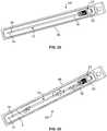
- Fig. 24illustrates an alternative embodiment of a package 46a that may be preferred for use in combination with an intermittent catheter 10g having a hydration device 22 that is manipulated by proximal movement away from the drainage funnel 20. While the package 46a of Fig. 24 may be preferred for use with a hydration device that is manipulated by proximal relative movement, it is also within the scope of the present disclosure for the illustrated package 46a to be used in combination with a hydration device that is configured to be otherwise manipulated for releasing hydrating fluid.
- the package 46a of Fig. 24includes an additional seal 48, which may seal the package 46a against the hydration device 22.
- the package 46ais separated into first and second sections 50 and 52, preferably with the intermittent catheter 10g being fully positioned within the second or lower section 52 of the package 46a.
- the first section 50 of the package 46a(which may be an unsealed section) may be manipulated to partially separate or break or open the sealed second section 50, without separating or opening the seal 48 between the package 46a and the hydration device 22.
- the first section 50 of the package 46aincludes or defines a formation 54, such as a finger hole, for improved gripping and handling of the package 46a by a user when manipulating the first section 50.
- the sealed second section 50is only separated to the extent necessary to access the distal end of the drainage funnel 20, as shown in Fig. 25 .
- Fig. 26shows the seal 48 being present between the distal end or portion of the hydrating device 22 and the package 46a to provide a fluid-tight interface, but it is within the scope of the present disclosure for the seal 48 be between the package 46a and other surfaces of the hydrating device 22.
- the hydration device 22may be manipulated to release hydrating fluid F into the second section 52 of the package 46a.
- Figs. 26 and 27show the drainage funnel 20 being moved distally with respect to the hydration device 22 to release hydrating fluid F, but it is within the scope of the present disclosure for the hydration device 22 to be otherwise manipulated to release hydrating fluid F.
- the package 46aWith hydrating fluid F in the second section 52 of the package 46a, the package 46a may be manipulated (e.g., by rotating or shaking it) to agitate the hydrating fluid F within the second section 52, thereby better coating the catheter shaft 12 with hydrating fluid F.
- the fluid-tight seal 48 between the package 46a and the hydration device 22remains intact, hydrating fluid F is prevented from leaking out of the second section 52 between the hydration device 22 and the seal 48, even when the package 46a is inverted ( Fig. 28 ).
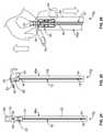
- the seal 48may be peeled apart or broken or opened to separate the package 46a from the hydration device 22, allowing the hydration device 22 and the intermittent catheter 10g to be removed ( Fig. 29 ) for advancement into a body lumen, as described above.
- Figs. 30 and 31illustrate an embodiment of an intermittent catheter 10h having a protective sleeve 56 surrounding at least a portion of the catheter shaft 12 to separate the enclosed portion of the catheter shaft 12 from the outside environment.
- the protective sleeve 56may be sealed to the hydration device 22 at or adjacent to a distal portion of the sleeve 56 and sealed about the catheter shaft 12 at or adjacent to a proximal portion of the sleeve 56.
- the hydration device 22Prior to advancement of the catheter shaft 12 into a body lumen, the hydration device 22 may be manipulated (as described above) to release hydrating fluid F into the sleeve 56, as shown in Fig.
- the catheter shaft 12may be moved proximally with respect to the sleeve 56 (while handling the catheter shaft 12 with the sleeve 56) to advance the lubricated catheter shaft 12 into a body lumen.
- the hydration device 22it may be preferred for the hydration device 22 to remain secured to the drainage funnel 20 during use, but it is also within the scope of the present disclosure for the hydration device 22 to be moved off of the drainage funnel 20 during use.
- Figs. 32 and 33illustrate an embodiment of an intermittent catheter 10i having a protective sleeve 56 and an introducer tip 58.
- the intermittent catheter 12may be initially positioned within a package 46 of the type described herein or according to any other suitable design.
- the introducer tip 58may be initially positioned within a protective cap 60 that encircles and covers a proximal section of the introducer tip 58.
- the introducer tip 58may be provided according to conventional design, associated with the proximal end portion 14 of the catheter shaft 12 and having a proximal section which is advanced into the body lumen prior to proximally advancing the catheter shaft 12 out of the introducer tip 58 and into the body lumen.
- the protective sleeve 56may be sealed to the hydration device 22 at or adjacent to a distal portion of the sleeve 56 and sealed to a distal section of the introducer tip 58 at or adjacent to a proximal portion of the sleeve 56.
- the hydration device 22may be manipulated (as described above) to release hydrating fluid F into the sleeve 56, as shown in Fig. 33 , to wet or lubricate the portion of the catheter shaft 12 positioned within the sleeve 56. Thereafter, the cap 60 may be removed from the introducer tip 58 and then the proximal section of the introducer tip 58 may be positioned within a body lumen.
- the catheter shaft 12may be moved proximally with respect to the introducer tip 58 to advance the wetted or lubricated catheter shaft 12 out of the introducer tip 58 and into the body lumen.
- the hydration device 22it may be preferred for the hydration device 22 to remain secured to the drainage funnel 20 during use, but it is also within the scope of the present disclosure for the hydration device 22 to be moved off of the drainage funnel 20 during use.
- Figs. 34 and 35illustrate another embodiment of an intermittent catheter 10j having a protective sleeve 56 and an introducer tip 58.
- the intermittent catheter 10j of Figs. 34 and 35may be configured and used according to the foregoing description of the embodiment of Figs. 32 and 33 , but with the inclusion of a second protective sleeve 62.
- the second sleeve 62which is secured at one end to the drainage funnel 20 and at another end to the hydration device 22 in the illustrated embodiment, may be substantially identical to the first sleeve 56 or may be differently configured.
- the hydration device 22may be moved proximally along the catheter shaft 12 (e.g., when being used as a gripper device) without uncovering the portion of the catheter shaft 12 that is distal of the hydration device 22.
- the hydration device 22is of the type that is manipulated by squeezing to release hydrating fluid, the user may regulate the amount of hydrating fluid F applied to the catheter shaft 12 by squeezing the hydration device 22 while advancing the hydration device 22 along the catheter shaft 12. This may be especially preferred when the fluid is a lubricating fluid, such as an oil or gel.
- Fig. 36illustrates an embodiment of an intermittent catheter 10k having an alternative package 64.
- the intermittent catheter 10kincludes a catheter shaft 12 extending between a drainage funnel 20 at its distal end portion 16 and an introducer tip 66 at its proximal end portion.
- the drainage funnel 20preferably includes an associated hydration device 22 of the type described herein.
- the introducer tip 66 of the intermittent catheter 10k of Fig. 36may be provided according to conventional design, but preferably is configured as shown in Figs. 37 and 38 .
- the introducer tip 66 of Figs. 37 and 38includes a proximal section 68 configured to be advanced into a body lumen.
- the proximal section 68may include a proximal end 70 that is configured to move from a closed condition to an open condition for proximal passage of the catheter shaft 12 therethrough.
- the proximal end 70 of the introducer tip 66is defined by a plurality of flaps or petals that close the hollow proximal section 68 of the introducer tip 66 in the illustrated closed condition, but are sufficiently flexed to be pressed outwardly as the catheter shaft 12 is advanced proximally with respect to the introducer tip 66 to open the proximal end 70 for advancement of the catheter shaft 12 out of the introducer tip 66 and into a body lumen.
- the introducer tip 66also includes a distal section 72 having a greater diameter than the proximal section 68.
- the illustrated distal section 72includes a barrel portion 74 and a rim portion 76.
- the illustrated barrel section 74is generally tubular or annular and substantially coaxial with the proximal section 68 of the introducer tip 66.
- the barrel portion 74is configured to have a greater diameter than the body lumen into which the proximal section 68 is to be advanced. By such a configuration, the barrel portion 74 abuts the body when the introducer tip 66 has been sufficiently advanced into the body lumen, thereby preventing over-insertion of the introducer tip 66 into the body lumen.
- the rim portion 76may be generally tubular or annular and surround or encircle the barrel portion 74.
- the illustrated rim portion 76is in contact with the barrel portion 74 in at least one location and spaced away from the barrel portion 74 in at least one location so as to define at least one opening 78 between the barrel portion 74 and the rim portion 76.
- the rim portion 76contacts the barrel portion 74 at two locations and spaced away from the barrel portion 74 at two locations to define two openings 78 between the barrel portion 74 and the rim portion 76.
- the barrel portion 74is substantially symmetrical and defines two diametrically opposed, mirror-image openings 78, but it is also within the scope of the present disclosure for the barrel and rim portions to define more than two openings and/or differently shaped openings and/or openings that are differently arranged around the barrel portion.
- the introducer tip 66 of Figs. 37 and 38may be advantageous in that its openings 78 allow for hydrating fluid released from the hydration device 22 to flow proximally along the catheter shaft 12 and then through the openings 78 to contact and lubricate the proximal section 68 of the introducer tip 66.
- the catheter shaft 12, drainage funnel 20, hydration device 22, and introducer tip 66are positioned within a sleeve package 64, as shown in Fig. 36 .
- the sleeve package 64is similar to the package 46a of Fig. 24 , but includes an additional seal, which defines a third section.
- the sleeve package 64includes proximal and distal end seals 80 and 82 at or adjacent to its ends. Two opposing surfaces or sheets of the sleeve package 64 are sealed together to seal the interior of the sleeve package 64 from the outside environment.
- the sleeve package 64further includes proximal and distal intermediate seals 84 and 86, with the proximal intermediate seal 84 being between the sleeve package 64 and the rim portion 76 of the introducer tip 66, and the distal intermediate seal 86 being between the sleeve package 64 and the hydration device 22.
- a sealed proximal chamber 88is defined between the proximal end seal 80 and the proximal intermediate seal 84 and receives a portion of the introducer tip 66 (namely, the proximal section 68 of the introducer tip 66).
- a sealed distal chamber 90is defined between the distal end seal 82 and the distal intermediate seal 86 and receives a portion of the drainage funnel 20.
- a sealed intermediate chamber 92is defined between the proximal intermediate seal 84 and the distal intermediate seal 86 and receives a portion of the catheter shaft 12.
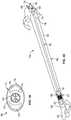
- the distal end seal 82may be opened by a user (e.g., by tearing it or peeling it apart) to open the sealed distal chamber 90, thereby allowing direct access to the drainage funnel 20 and/or a portion of the hydration device 22 ( Fig. 39 ).
- the usermay manipulate the hydration device 22 to release hydrating fluid F into the sealed intermediate chamber 92, where it contacts and coats the catheter shaft 12.
- the hydrating fluidflows proximally along the catheter shaft 12 and through the openings 78 of the introducer tip 66 into the sealed proximal chamber 88, where the hydrating fluid lubricates the proximal section 68 of the introducer tip 66.
- the hydrating fluidmay be a lubricant itself or a fluid that interacts with a coating of the introducer tip 66 (e.g., a hydrophilic coating) to lubricate the introducer tip 66.
- a coating of the introducer tip 66e.g., a hydrophilic coating
- the hydrating fluidmay be released prior to opening the sealed distal section 90.
- the usermay open the proximal end seal 80 (e.g., by tearing it or peeling it apart) to open the sealed proximal chamber 88.
- the intermediate seals 84 and 86remain intact, thereby maintaining the integrity of the sealed intermediate section 92 of the sleeve package 64, which acts as a protective sleeve during use of the intermittent catheter 10k.
- the introducer tip 66may be advanced into the body lumen up to the point that the barrel portion 74 of the distal section 72 contacts the body.
- the catheter shaft 12may be advanced proximally with respect to the introducer tip 66 (e.g., by gripping the hydration device 22 and moving it and the catheter shaft 12 toward the body lumen) to advance the catheter shaft 12 proximally out of the introducer tip 66 and into the body lumen, as described above.
Landscapes
- Health & Medical Sciences (AREA)
- Life Sciences & Earth Sciences (AREA)
- Hematology (AREA)
- Animal Behavior & Ethology (AREA)
- Engineering & Computer Science (AREA)
- Anesthesiology (AREA)
- Biomedical Technology (AREA)
- Heart & Thoracic Surgery (AREA)
- Veterinary Medicine (AREA)
- Public Health (AREA)
- General Health & Medical Sciences (AREA)
- Pulmonology (AREA)
- Biophysics (AREA)
- Otolaryngology (AREA)
- Media Introduction/Drainage Providing Device (AREA)
- External Artificial Organs (AREA)
Description
- The present disclosure generally relates to intermittent catheters. More particularly, the present disclosure relates to intermittent catheters having an associated device for hydrating and/or gripping the catheter.
- Intermittent catheterization is a good option for many users who suffer from various abnormalities and pathologies of the urinary system and its nerve supply. Such catheters are typically provided as single use, individually packaged items and may include a gel-lubricant or hydrophilic coating as a lubricant for reducing friction during insertion into the urethra.
- Regarding gel-coated catheters, a user applies a gel-lubricant, such as a water-based gel-lubricant, to the surface of the shaft of the catheter, which reduces friction for ease of insertion into the urethra. In some instances, the gel- lubricant is supplied with the packaged catheter, in which case the gel-lubricant may be applied to the catheter shaft just before or during the packaging operation or as the catheter shaft is being inserted by the user.
- When a hydrophilic material is used as a lubricant, a thin coating of hydrophilic material is applied to the outer surface of the catheter shaft, and may subsequently be radiation- or heat-cured. When this coating is activated by swelling in contact with a hydrating liquid or wetting agent such as water, it provides a hydrated surface having an extremely low coefficient of friction. One form of this product provides a sterile, individually packaged, single-use catheter in a dry state or condition. The user opens the package, pours water into the package, waits 30 seconds, and then removes the catheter from the package, which is now ready for insertion. Other examples provide the amount of wetting agent necessary for immersion of the catheter shaft in a separate compartment of the package. In such examples, the user must open the separate compartment of the package to allow the wetting agent to enter the catheter shaft-containing chamber for direct contact with the hydrophilic coated surface. The catheter is then removed from the package and the catheter shaft is inserted into the urethra. In yet another example, the ready-to-use catheter is provided in a package that already contains enough loose wetting agent to cause it to be immersed. In such an example, the user simply opens the package and removes the catheter therefrom, and then inserts the catheter shaft into the urethra, without the need to add the wetting agent.
- Examples of such known catheter systems are disclosed in
US 2001/001443 andUS 2005/043715 . - There are several aspects of the present subject matter which may be embodied separately or together in the devices and systems described below. These aspects may be employed alone or in combination with other aspects of the subject matter described herein, and the description of these aspects together is not intended to preclude the use of these aspects separately or the claiming of such aspects separately or in different combinations as set forth in the claims appended hereto. In one aspect, an intermittent catheter includes a catheter shaft extending between a proximal end portion and a distal end portion, with a drainage member associated with the distal end portion of the catheter shaft. A hydration device encircles at least a portion of the drainage member and defines a hydrating fluid- containing reservoir in fluid communication with at least one fluid-release port. The hydration device is configured to be manipulated by a user to move the at least one fluid-release port from a closed condition to an open condition to flow at least a portion of the hydrating fluid out of the reservoir via the at least one fluid- release port for covering at least a portion of the catheter shaft.
- In another aspect, an intermittent catheter includes a catheter shaft extending between a proximal end portion and a distal end portion, with an introducer tip associated with the proximal end portion of the catheter shaft. The introducer tip has proximal and distal sections, with the distal section having a barrel portion and a rim portion surrounding the barrel portion. The rim portion is in contact with the barrel portion in at least one location and spaced away from the barrel portion in at least one location to define at least one opening between the barrel and rim portions.
- In yet another aspect, a method is provided for hydrating an intermittent catheter. The method involves providing an intermittent catheter including a catheter shaft extending between a proximal end portion and a distal end portion. A drainage member is associated with the distal end portion of the catheter shaft, and a hydration device encircles at least a portion of the drainage member. The hydration device defines a hydrating fluid-containing reservoir in fluid communication with at least one fluid-release port. The hydration device is manipulated to move the at least one fluid-release port from a closed condition to an open condition to flow at least a portion of the hydrating fluid out of the reservoir via the at least one fluid-release port, thereby covering at least a portion of the catheter shaft with the hydrating fluid.
- In another aspect, a method is provided for hydrating an intermittent catheter. The method involves providing an intermittent catheter including a catheter shaft extending between a proximal end portion and a distal end portion, with an introducer tip associated with the proximal end portion. A hydrating fluid is applied to the catheter shaft and the introducer tip, with the hydrating fluid first being applied to a portion of the catheter shaft positioned distally of the introducer tip. The hydrating fluid then flows proximally along the catheter shaft to contact a distal section of the introducer tip. The hydrating fluid next flows proximally through at least one opening defined by the distal section of the introducer tip to contact a proximal section of the introducer tip.
- In accordance with the present invention, there is provided an intermittent catheter system as defined in claim 1 and a method of hydrating an intermittent catheter as defined in claim 9. In addition, further advantageous embodiments follow from the dependent claims.
Fig. 1 is a perspective view of an intermittent catheter having a hydration device according to an aspect of the present disclosure;Fig. 2 is a perspective view of the intermittent catheter ofFig. 1 , showing the hydration device being secured to a drainage funnel of the catheter;Fig. 3 is a perspective view of the intermittent catheter ofFig. 1 , with the hydration device being manipulated to release a hydrating fluid;Fig. 4 is a perspective view of an alternative embodiment of an intermittent catheter having a hydration device;Fig. 5 is a side elevational view of the intermittent catheter ofFig. 4 ;Fig. 6 is an end view of the hydration device ofFig. 4 , with fluid-release ports thereof in a closed condition;Fig. 7 is an end view of the hydration device ofFig. 4 , with fluid-release ports thereof in an open condition;Fig. 8 is an end view of an alternative embodiment of a hydration device, with fluid-release ports thereof in a closed condition;Fig. 9 is an end view of the hydration device ofFig. 8 , with fluid-release ports thereof in an open condition;Fig. 10 is a perspective view of another alternative embodiment of an intermittent catheter having a hydration device;Fig. 11 is a side elevational view of the intermittent catheter ofFig. 10 ;Fig. 12 is a cross-sectional view of the intermittent catheter ofFig. 10 ;Fig. 13 is a cross-sectional view of the hydration device ofFig. 10 ;Fig. 14 is a side elevational view of the intermittent catheter ofFig. 10 , with the hydration device being separated from a drainage funnel to release hydrating fluid from the hydration device;Fig. 15 is a front elevational view of the intermittent catheter ofFig. 10 , with the hydration device separated from the drainage funnel to release hydrating fluid from the hydration device;Figs. 16 and17 are cross-sectional view of the intermittent catheter ofFig. 10 , with the hydration device separated from the drainage funnel to release hydrating fluid from the hydration device;Figs. 18 and 19 are perspective views of an intermittent catheter having a hydration device, with the hydration device being used as a gripper device;Fig. 20 is a cross-sectional view of the hydration device ofFig. 18 ;Fig. 21 is a cross-sectional view of an alternative embodiment of a hydration device which may be used as a gripper device;Fig. 22 is a perspective view of an intermittent catheter incorporating a package;Fig. 23 is a perspective view of the intermittent catheter ofFig. 22 , with a hydration device of the intermittent catheter releasing hydrating fluid into the package to contact a catheter shaft of the intermittent catheter;Fig. 24 is a side elevational view of an alternative embodiment of an intermittent catheter incorporating a package;Fig. 25 is a side elevational view of the intermittent catheter ofFig. 24 , with a distal portion of the package being opened to access a drainage funnel and hydration device of the catheter;Figs. 26 and27 are side elevational views of the intermittent catheter ofFig. 24 , with the hydration device being manipulated to release hydrating fluid therefrom into the package to contact a catheter shaft of the catheter;Fig. 28 is a perspective view of the intermittent catheter ofFig. 24 , with the package being manipulated to apply hydrating fluid to the catheter shaft;Fig. 29 is a perspective view of the intermittent catheter ofFig. 24 , with the intermittent catheter being removed from the package for use;Fig. 30 is a perspective view of an embodiment of an intermittent catheter having a hydration device and a sleeve;Fig. 31 is a perspective view of the intermittent catheter ofFig. 30 , with the hydration device having been manipulated to release hydrating fluid into the sleeve;Fig. 32 is a perspective view of an embodiment of an intermittent catheter having a sleeve secured to a hydration device and an introducer tip, positioned within a package;Fig. 33 is a perspective view of the intermittent catheter ofFig. 32 , removed from the package for use;Fig. 34 is a perspective view of an embodiment of an intermittent catheter having a pair of sleeves secured to a hydration device, with the hydration device in an initial position;Fig. 35 is a perspective view of the intermittent catheter ofFig. 34 , with the hydration device moved proximally along a catheter shaft of the catheter;Fig. 36 is a perspective view of an embodiment of an intermittent catheter positioned within a sleeve package;Fig. 37 is a perspective view of an introducer tip of the intermittent catheter ofFig. 36 ;Fig. 38 is a top plan view of the introducer tip of the intermittent catheter ofFig. 38 ; andFig. 39 is a perspective view of the intermittent catheter ofFig. 36 , with a sealed proximal chamber and a sealed distal chamber of the sleeve package being opened for use of the catheter.- The embodiments disclosed herein are for the purpose of providing a description of the present subject matter, and it is understood that the subject matter may be embodied in various other forms and combinations not shown in detail. Therefore, specific embodiments and features disclosed herein are not to be interpreted as limiting the subject matter as defined in the accompanying claims.
- References to "embodiments" throughout the description which are not under the scope of the appended claims represent possible examples and are therefore not part of the present invention unless the context clearly dictates otherwise. The invention is defined by the appended claims.
Figs. 1-3 show a distal portion of anintermittent catheter 10 according to an aspect of the present disclosure. Theintermittent catheter 10 will be described herein in terms of its applicability for catheterization of a male urethra, but it should be understood that catheters according to the present disclosure may be used for other applications as well.- The illustrated
intermittent catheter 10 includes a generallyflexible catheter shaft 12, which extends between a closed proximal end portion 14 (Fig. 18 ) and an opendistal end portion 16. Thecatheter shaft 12 may be provided generally according to conventional design, such as with one or more openings oreyes 18 associated with theproximal end portion 14 for flowing a fluid from the outside environment into the hollow interior of thecatheter shaft 12. Thedistal end portion 16 is illustrated with an associated drainage member, such as afunnel 20, which may be a generally rigid component that is secured to thedistal end portion 16 of thecatheter shaft 12. Thedrainage funnel 20 may be configured to direct fluid from out of the interior of thecatheter shaft 12 to a collection container or disposal device, such as a toilet. Thecatheter shaft 12 may be provided as a hydrophilic catheter shaft, in which case it may include a hydrophilic outer surface along at least a portion of its length. If provided, the hydrophilic portion of the catheter shaft becomes lubricious when wetted or hydrated with a hydration fluid, such as water or saline. All or a portion of the catheter shaft itself may have hydrophilic properties or, alternatively, a coating may be applied to at least a portion of the outer surface of the catheter shaft to give the coated portion hydrophilic properties. - The
intermittent catheter 10 further includes ahydration device 22. As used herein, the term "hydration device" is intended to refer broadly to a device of the type to be described herein, rather than being limited to particular uses or fluid contents. For example, it should be understood that a "hydration device" may be used for either hydrating or lubricating a portion of a catheter shaft and may contain either a hydrating or lubricating fluid, as will be described below. - The
hydration device 22 is associated with and encircles at least a portion of the drainage funnel 20 (Figs. 1 and3 ).Fig. 2 shows a step of the process of assembling theintermittent catheter 10, in which theproximal end portion 14 of thecatheter shaft 12 is advanced into acentral cavity 24 defined by the generallytubular hydration device 22. Thehydration device 22 is advanced distally along thecatheter shaft 12 until thedrainage funnel 20 is at least partially positioned within thecavity 24, as inFigs. 1 and3 . Preferably, thecavity 24 of thehydration device 22 is configured to engage and be retained upon thedrainage funnel 20, such that thehydration device 22 remains connected to thehydration device 22 after pressing thehydration device 22 distally onto thedrainage funnel 20. In one embodiment, thecavity 24 of thehydration device 22 may have a shape that complements the shape of thedrainage funnel 20. The hydration device 22 (or at least the portion thereof which defines the cavity 24) may have intermediate rigidity (i.e., greater flexibility than thedrainage funnel 20 and greater rigidity than the catheter shaft 12), which may be advantageous to allow thehydration device 22 to temporarily deform and pass over the contours of thedrainage funnel 20 as it is pressed onto thedrainage funnel 20. - The
hydration device 22 includes areservoir 26, which is defined between proximal anddistal ends outer walls hydration device 22. Thereservoir 26 is at least partially filled with a hydrating fluid F, which is applied to at least a portion of thecatheter shaft 12 prior to insertion of thecatheter shaft 12 into a body lumen. The nature of the hydrating fluid F may vary without departing from the scope of the present disclosure. For example, in one embodiment, the hydrating fluid comprises water or another wetting fluid, which interacts with hydrophilic material of thecatheter shaft 12 to provide a lubricated surface. In other embodiments, a gel or oil or other lubricating fluid may be provided as a hydrating fluid F, and the present disclosure is not limited to a particular hydrating or lubricating fluid. Preferably, thereservoir 26 is at least partially filled with the hydrating fluid F prior to advancing thehydration device 22 onto thedrainage funnel 20, but it is also within the scope of the present disclosure for thehydration device 22 to be secured to thedrainage funnel 20 prior to adding the hydrating fluid F into thereservoir 26. - The
reservoir 26 is provided in fluid communication with at least one fluid-release port or vent orseal 36. In the illustrated embodiment, theproximal end 28 includes a pair of fluid-release ports 36, which are positioned on opposite sides of thecavity 24, but it within the scope of the present disclosure for thehydration device 22 to include only one fluid-release port or more than two fluid-release ports and/or for the fluid-release port(s) to be located at a different position than shown inFigs. 1-3 . Thehydration device 22 is resiliently deformable in the vicinity of the fluid-release ports 36, such that the fluid-release ports 36 may be manipulated by a user to move the fluid-release ports between a closed condition (Figs. 1 and 2 ) and an open condition (Fig. 3 ). In the closed condition, the fluid-release ports 36 provide seals, which prevents the release of hydrating fluid F from thereservoir 26. In the open condition, the fluid-release ports 36 are at least partially open to allow for at least a portion of the hydrating fluid F to flow out of thereservoir 26 via the fluid-release ports 36. The fluid-release portions 36 may be sealed by any suitable means such as, but not limited to, friction, a heat seal, or an adhesive. - In use, the
intermittent catheter 10 is oriented with thedrainage funnel 20 positioned above thecatheter shaft 12. Thehydration device 22 is then manipulated by a user to move at least one of the fluid-release ports 36 from the closed condition to the open condition to allow at least a portion of the hydrating fluid F to flow out of thereservoir 26 via the fluid-release port(s) 36 to cover at least a portion of thecatheter shaft 12. The hydrating fluid F will wet the hydrophilic surface of the catheter shaft 12 (when a hydrophilic catheter shaft or coating is employed) or otherwise lubricate the catheter shaft 12 (when the catheter shaft is formed of a non-hydrophilic material and omits a hydrophilic coating). By positioning thedrainage funnel 20 above thecatheter shaft 12, the hydrating fluid F will flow from thedistal end portion 16 of thecatheter shaft 12 down to theproximal end portion 14 via gravity, thereby covering and coating thecatheter shaft 12 for increased lubricity. - When the
catheter shaft 12 has been lubricated by the application of hydrating fluid F, it may be advanced into a body lumen. In one exemplary procedure, theproximal end portion 14 of thecatheter shaft 12 is advanced into and through a urethra until theproximal end portion 14 reaches the bladder. When theproximal end portion 14 is positioned within the bladder, urine contained within the bladder will flow into the interior of thecatheter shaft 12 via the eye(s) 18. The urine then flows from theproximal end portion 14 of thecatheter shaft 12 to thedistal end portion 16, where it exits theintermittent catheter 12 via thedrainage funnel 20. Thereafter, thecatheter shaft 12 may be retracted from the urethra and theintermittent catheter 10 may be disposed of. - The
hydration device 22 may be manipulated in any suitable manner to open the fluid-release port(s) 36. For example, in one embodiment, theouter wall 34 of thehydration device 22 is pinched or squeezed to move it toward the inner wall 32 (Fig. 3 ), which causes the fluid-release port(s) 36 to resiliently deform from the closed condition to the open condition. When the fluid-release ports 36 are sealed by an adhesive or heat seal or the like, squeezing thehydration device 22 increases the pressure within thereservoir 26 until the pressure overcomes the strength of the seal, which bursts or yields to allow the release of hydrating fluid F. If thehydration device 22 is configured to be manipulated by squeezing or pinching, theouter wall 34 may be textured or contoured for improved handling. For example, in the illustrated embodiment, theouter wall 34 of thehydration device 22 includes a grippingportion 38, which is sufficiently flexible to be moved toward theinner wall 32. The outer surface of the illustrated grippingportion 38 has a smaller diameter than the outer surface of theouter wall 34, which may be sized and configured to receive the digits of a user, as shown inFig. 3 . Theouter wall 34 may be thinner at the grippingportion 38 than at other portions or may otherwise be more flexible than other portions of theouter wall 34, with the smaller diameter serving to encourage the user to place his digits onto the grippingportion 38. At least a portion of the outer surface of the grippingportion 38 may be textured or contoured (e.g., with ribs or knurls or the like) for improved handling. The material composition of thehydration device 22 or only the grippingportion 38 thereof may also provide improved handling. For example, thehydration device 22 or only the grippingportion 38 thereof may be formed of a soft elastomeric material, such as silicone, which may be gripped by a user without the digits of the user sliding along thehydration device 22 or grippingportion 38. Figs. 4-7 illustrate anintermittent catheter 10a with a variation of thehydration device 22 ofFigs. 1-3 . In the embodiment ofFigs. 4-7 , thehydration device 22a is similar to thehydration device 22 ofFigs. 1-3 , but with a differently configured grippingportion 38a. In the embodiment ofFigs. 1-3 , the grippingportion 38a is positioned approximately midway between the proximal anddistal ends hydration device 22, whereas thegripping portion 38a of thehydration device 22a ofFigs. 4-7 is positioned closer to theproximal end 28 than thedistal end 30. In other embodiments, the gripping portion (if provided) may be positioned closer to the distal end of the hydration device than to the proximal end. Additionally, the grippingportion 38 ofFigs. 1-3 is shown as being generally flat and featureless, while the grippingportion 38a ofFigs. 4-7 is shown withribs 40 for improved gripping and handling.Fig. 6 is an end view of thehydration device 22a, with the fluid-release ports 36 in a closed condition.Fig. 7 shows thehydration device 22a being manipulated by pinching or squeezing, which causes the fluid-release ports 36 to move from the closed condition to an open condition, as described above. In the illustrated embodiment, the fluid-release ports 36 are configured as radial slits, which are positioned on opposite sides of thecavity 24 of thehydration device 22a in a common line or plane (e.g., along a diameter of thehydration device 22a). When the fluid-release ports 36 are oriented as shown inFigs. 6 and 7 , they may be best opened by squeezing or pinching thehydration device 22a along the same line or in the same plane in which the fluid-release ports 36 lie, as shown inFigs. 7 , although they may also be opened by pinching or squeezing thehydration device 22a along a different line or in a different (preferably non-perpendicular) plane. If the hydration device has a preferred line or plane of manipulation, the hydration device or the gripping portion (if provided) may be configured to alert the user to the preferred line or plane of manipulation. For example, the hydration device may have graphics or colors that highlight the preferred line or plane of manipulation or may be non-symmetrical to alert the user to the preferred line or plane of manipulation.Figs. 8 and 9 illustrate an alternative embodiment of ahydration device 22b. In the embodiment ofFigs. 8 and 9 , thehydration device 22b includes fluid-release ports cavity 24 of thehydration device 22b, but it is also within the scope of the present disclosure for there to be a different number of fluid-release ports and for the fluid-release ports to be non-symmetrically arranged around thecavity 24. Each fluid-release port may be in fluid communication with a common reservoir. Alternatively, a hydration device may be provided with a plurality of reservoirs, with each reservoir being in fluid communication with one or more different fluid-release ports.- With fluid-
release ports hydration device 22b along one line or plane may cause selected fluid-release ports to open to a different extent than other fluid-release ports. For example, in the orientation ofFigs. 8 and 9 , pinching or squeezing or manipulating thehydration device 22b along a horizontal line or in a horizontal plane (as inFig. 9 ), the fluid-release ports 36a which lie in that same line or plane will tend to open to a greater extent than the fluid-release ports 36b that are arranged along another line or plane. If the fluid-release ports release ports 36b may tend to remain in the closed condition, as shown inFig. 9 . Similarly, if thehydration device 22b is manipulated along a vertical line or plane (in the orientation ofFigs. 8 and 9 ), the fluid-release ports 36b arranged along that same line or in that same plane will tend to open, whereas the fluid-release ports 36a arranged along the perpendicular line or plane will tend to remain closed. - If the
hydration device 22b is manipulated along a line or plane that is different from (and preferably non-perpendicular to) the line or plane in which a fluid-release port Figs. 8 and 9 ), it may tend to cause that fluid-release port hydration device 22b ofFigs. 8 and 9 may be considered to be substantially omni-directional, to the extent that at least one of the fluid-release ports hydration device 22b is manipulated. In certain applications, a more direction-dependent configuration (e.g., the configuration ofFigs. 6 and 7 ) may be advantageous, whereas an omni-directional configuration (as in the configuration ofFigs. 8 and 9 ) may be preferred for other applications. Figs. 1-9 show hydration devices having fluid-release ports that are spaced away from the central cavity of the hydration device, but it is also within the scope of the present disclosure for at least one of the fluid-release ports to be in fluid communication with the central cavity (i.e., extending between the reservoir and the cavity). For example,Figs. 10-17 illustrate anintermittent catheter 10c having ahydration device 22c that may be provided generally according to the foregoing description of the hydration devices ofFigs. 1-9 , except that at least one fluid-release port 36c is in fluid communication with thecavity 24 defined inwardly of theinner wall 32 of thehydration device 22c.- The fluid-
release ports 36c may be configured to move between closed and open conditions by either deformation of the fluid-release ports 36c or by movement of thehydration device 22c with respect to thedrainage funnel 20. If the fluid-release ports 36c are configured to be deformed, then they may be provided as slits (as in the embodiments ofFigs. 1-9 ), with thehydration device 22c being pinched or squeezed or otherwise manipulated as described above to move the fluid-release ports 36c between open and closed conditions. When the fluid-release ports 36c have been moved into the open condition, hydrating fluid F flows out of thereservoir 26, through the fluid-release ports 36c, and into thecavity 24, where it contacts thedrainage funnel 20 and/or thecatheter shaft 12 for lubrication prior to advancement of thecatheter shaft 12 into a body lumen. - If the fluid-
release ports 36c are configured to be moved into an open condition by movement of thehydration device 22c with respect to thedrainage funnel 20, the fluid-release ports 36c may be defined by open passages (Fig. 13 ) rather than slits. Fluid flow through the fluid-release ports 36c may be initially prevented by a portion of thedrainage funnel 20 overlaying or plugging the fluid-release ports 36c (Figs. 10-12 ). The fluid-release ports 36c may be moved from this closed condition to an open condition by moving thehydration device 22c proximally along thecatheter shaft 12, away from the drainage funnel 20 (Figs. 14-17 ). So moving thehydration device 22c removes the blockage from the fluid-release ports 36c, thereby allowing hydrating fluid F to flow out of thereservoir 26, through the fluid-release ports 36c, and into contact with thecatheter shaft 12 for lubrication. If this mechanism is selected for opening the fluid-release ports 36c, thehydration device 22c may be formed of a more rigid material than what may be preferred when the fluid-release ports are opened by pinching or squeezing. However, it may be advantageous for at least theinner wall 32 of thehydration device 22c to be semi-flexible to allow thehydration device 22c to be pressed onto thedrainage funnel 20 for an interference fit and later separated from thedrainage funnel 20 to release hydrating fluid F. - After releasing hydrating fluid (or while releasing hydrating fluid), the hydrating device may be used as a gripper device for handling the intermittent catheter. For example,
Fig. 18 shows ahydration device 22d secured to thedrainage funnel 20 of anintermittent catheter 10d. If thehydration device 22d is configured to release hydrating fluid by pinching or squeezing or the like, then it may be moved proximally along the catheter shaft 12 (Fig. 19 ) after being manipulated. Alternatively, thehydration device 22d may be moved proximally along thecatheter shaft 12 prior to or while manipulating thehydration device 22d to release hydrating fluid. If thehydration device 22d is configured to be moved proximally along thecatheter shaft 12, then it may continue releasing hydrating fluid as it is moved away from thedrainage funnel 20 and along thecatheter shaft 12. - With the
hydration device 22d encircling thecatheter shaft 12, it may be pinched or squeezed to move theouter wall 34 into engagement with theinner wall 32, which may then be further pressed inwardly to engage thecatheter shaft 12. This causes thehydration device 22d to grip thecatheter shaft 12, thereby allowing the user to handle and manipulate the catheter shaft 12 (including advancing theproximal end portion 14 of thecatheter shaft 12 into a body lumen) by holding thehydration device 22d rather than the lubricatedcatheter shaft 12. - The
hydration device 22d may include one or more features or formations for improved functionality as a gripper device. For example,Fig. 20 shows theouter wall 34 of thehydration device 22d having an extension orgripping aid 42, which may be associated with the gripping portion 38 (if provided). Theextension 42 is positioned on an inner surface of theouter wall 34, within thereservoir 26, and extends toward theinner wall 32, preferably without contacting theinner wall 32. When theouter wall 34 is pressed toward theinner wall 32, theextension 42 is brought into contact with the outer surface of theinner wall 32. Compared to a hydration device omitting an extension, theextension 42 effectively positions theouter wall 34 closer to theinner wall 32, thereby allowing for a smaller deformation of theouter wall 34 to effectively place theouter wall 34 into contact with theinner wall 32. Fig. 21 shows an embodiment in which both the outer andinner walls hydration device 22e of theintermittent catheter 10e include radially inwardly extending extensions orgripping aids extension 44 of theinner wall 32 is positioned on an inner surface of theinner wall 32, within thecentral cavity 24 of thehydration device 22e. Preferably, theextension 44 of theinner wall 32 is generally aligned with the grippingportion 38 and/or theextension 42 of theouter wall 34, if provided. When theinner wall 32 is pressed toward thecatheter shaft 12, theextension 44 is brought into contact with thecatheter shaft 12. Compared to a hydration device omitting such an extension, theextension 44 effectively positions theinner wall 32 closer to thecatheter shaft 12, thereby allowing for a smaller deformation of theinner wall 32 to effectively place theinner wall 32 into contact with thecatheter shaft 12. Providing bothextensions catheter shaft 12 with thehydration device 22e, but it is also within the scope of the present disclosure for only one of the walls of the hydration device to include an extension or for neither of the walls to include an extension.- In addition to the basic components illustrated in
Figs. 1-21 , intermittent catheters according to the present disclosure may be provided with additional components without departing from the scope of the present disclosure. For example,Figs. 22 and 23 show anintermittent catheter 10f positioned within a sealedpackage 46. In the embodiment ofFigs. 22 and 23 , thehydration device 22 may be manipulated (e.g., by pinching or squeezing or being moved proximally along the catheter shaft 12) to release hydrating fluid F into the sealed package 46 (Fig. 23 ). Thepackage 46 may be manipulated (e.g., by rotating or shaking it) to agitate the hydrating fluid F within thepackage 46, thereby better coating thecatheter shaft 12 with hydrating fluid F. Thereafter, thepackage 46 may be opened to remove theintermittent catheter 10f for advancement into a body lumen, as described above. Fig. 24 illustrates an alternative embodiment of apackage 46a that may be preferred for use in combination with anintermittent catheter 10g having ahydration device 22 that is manipulated by proximal movement away from thedrainage funnel 20. While thepackage 46a ofFig. 24 may be preferred for use with a hydration device that is manipulated by proximal relative movement, it is also within the scope of the present disclosure for the illustratedpackage 46a to be used in combination with a hydration device that is configured to be otherwise manipulated for releasing hydrating fluid.- Compared to the
package 46 ofFigs. 22 and 23 , thepackage 46a ofFig. 24 includes anadditional seal 48, which may seal thepackage 46a against thehydration device 22. Thepackage 46a is separated into first andsecond sections intermittent catheter 10g being fully positioned within the second orlower section 52 of thepackage 46a. - In use, the
first section 50 of thepackage 46a (which may be an unsealed section) may be manipulated to partially separate or break or open the sealedsecond section 50, without separating or opening theseal 48 between thepackage 46a and thehydration device 22. In the illustrated embodiment, thefirst section 50 of thepackage 46a includes or defines aformation 54, such as a finger hole, for improved gripping and handling of thepackage 46a by a user when manipulating thefirst section 50. Preferably, the sealedsecond section 50 is only separated to the extent necessary to access the distal end of thedrainage funnel 20, as shown inFig. 25 . When thesecond section 50 has only been separated to this limited extent, theseal 48 between thehydration device 22 and thepackage 46a remains intact, thereby retaining a fluid-tight interface therebetween.Fig. 26 shows theseal 48 being present between the distal end or portion of the hydratingdevice 22 and thepackage 46a to provide a fluid-tight interface, but it is within the scope of the present disclosure for theseal 48 be between thepackage 46a and other surfaces of the hydratingdevice 22. - With the
second section 50 partially opened, thehydration device 22 may be manipulated to release hydrating fluid F into thesecond section 52 of thepackage 46a.Figs. 26 and27 show thedrainage funnel 20 being moved distally with respect to thehydration device 22 to release hydrating fluid F, but it is within the scope of the present disclosure for thehydration device 22 to be otherwise manipulated to release hydrating fluid F. - With hydrating fluid F in the
second section 52 of thepackage 46a, thepackage 46a may be manipulated (e.g., by rotating or shaking it) to agitate the hydrating fluid F within thesecond section 52, thereby better coating thecatheter shaft 12 with hydrating fluid F. As the fluid-tight seal 48 between thepackage 46a and thehydration device 22 remains intact, hydrating fluid F is prevented from leaking out of thesecond section 52 between thehydration device 22 and theseal 48, even when thepackage 46a is inverted (Fig. 28 ). Thereafter, theseal 48 may be peeled apart or broken or opened to separate thepackage 46a from thehydration device 22, allowing thehydration device 22 and theintermittent catheter 10g to be removed (Fig. 29 ) for advancement into a body lumen, as described above. Figs. 30 and 31 illustrate an embodiment of anintermittent catheter 10h having aprotective sleeve 56 surrounding at least a portion of thecatheter shaft 12 to separate the enclosed portion of thecatheter shaft 12 from the outside environment. Theprotective sleeve 56 may be sealed to thehydration device 22 at or adjacent to a distal portion of thesleeve 56 and sealed about thecatheter shaft 12 at or adjacent to a proximal portion of thesleeve 56. Prior to advancement of thecatheter shaft 12 into a body lumen, thehydration device 22 may be manipulated (as described above) to release hydrating fluid F into thesleeve 56, as shown inFig. 31 , to lubricate the portion of thecatheter shaft 12 positioned within thesleeve 56. Thereafter, thecatheter shaft 12 may be moved proximally with respect to the sleeve 56 (while handling thecatheter shaft 12 with the sleeve 56) to advance the lubricatedcatheter shaft 12 into a body lumen. In the embodiment ofFigs. 30 and 31 , it may be preferred for thehydration device 22 to remain secured to thedrainage funnel 20 during use, but it is also within the scope of the present disclosure for thehydration device 22 to be moved off of thedrainage funnel 20 during use.Figs. 32 and 33 illustrate an embodiment of anintermittent catheter 10i having aprotective sleeve 56 and anintroducer tip 58. Theintermittent catheter 12 may be initially positioned within apackage 46 of the type described herein or according to any other suitable design. Theintroducer tip 58 may be initially positioned within aprotective cap 60 that encircles and covers a proximal section of theintroducer tip 58. Theintroducer tip 58 may be provided according to conventional design, associated with theproximal end portion 14 of thecatheter shaft 12 and having a proximal section which is advanced into the body lumen prior to proximally advancing thecatheter shaft 12 out of theintroducer tip 58 and into the body lumen. Theprotective sleeve 56 may be sealed to thehydration device 22 at or adjacent to a distal portion of thesleeve 56 and sealed to a distal section of theintroducer tip 58 at or adjacent to a proximal portion of thesleeve 56.- Prior to advancement of the
introducer tip 58 and thecatheter shaft 12 into a body lumen, thehydration device 22 may be manipulated (as described above) to release hydrating fluid F into thesleeve 56, as shown inFig. 33 , to wet or lubricate the portion of thecatheter shaft 12 positioned within thesleeve 56. Thereafter, thecap 60 may be removed from theintroducer tip 58 and then the proximal section of theintroducer tip 58 may be positioned within a body lumen. With theintroducer tip 58 partially positioned within the body lumen, thecatheter shaft 12 may be moved proximally with respect to theintroducer tip 58 to advance the wetted or lubricatedcatheter shaft 12 out of theintroducer tip 58 and into the body lumen. In the embodiment ofFigs. 32 and 33 , it may be preferred for thehydration device 22 to remain secured to thedrainage funnel 20 during use, but it is also within the scope of the present disclosure for thehydration device 22 to be moved off of thedrainage funnel 20 during use. Figs. 34 and 35 illustrate another embodiment of anintermittent catheter 10j having aprotective sleeve 56 and anintroducer tip 58. Theintermittent catheter 10j ofFigs. 34 and 35 may be configured and used according to the foregoing description of the embodiment ofFigs. 32 and 33 , but with the inclusion of a secondprotective sleeve 62. Thesecond sleeve 62, which is secured at one end to thedrainage funnel 20 and at another end to thehydration device 22 in the illustrated embodiment, may be substantially identical to thefirst sleeve 56 or may be differently configured. By providing asecond sleeve 62, thehydration device 22 may be moved proximally along the catheter shaft 12 (e.g., when being used as a gripper device) without uncovering the portion of thecatheter shaft 12 that is distal of thehydration device 22. Additionally, if thehydration device 22 is of the type that is manipulated by squeezing to release hydrating fluid, the user may regulate the amount of hydrating fluid F applied to thecatheter shaft 12 by squeezing thehydration device 22 while advancing thehydration device 22 along thecatheter shaft 12. This may be especially preferred when the fluid is a lubricating fluid, such as an oil or gel.Fig. 36 illustrates an embodiment of anintermittent catheter 10k having analternative package 64. In the embodiment ofFig. 36 , theintermittent catheter 10k includes acatheter shaft 12 extending between adrainage funnel 20 at itsdistal end portion 16 and anintroducer tip 66 at its proximal end portion. Thedrainage funnel 20 preferably includes an associatedhydration device 22 of the type described herein.- The
introducer tip 66 of theintermittent catheter 10k ofFig. 36 may be provided according to conventional design, but preferably is configured as shown inFigs. 37 and38 . Theintroducer tip 66 ofFigs. 37 and38 includes aproximal section 68 configured to be advanced into a body lumen. Theproximal section 68 may include aproximal end 70 that is configured to move from a closed condition to an open condition for proximal passage of thecatheter shaft 12 therethrough. For example, in the illustrated embodiment theproximal end 70 of theintroducer tip 66 is defined by a plurality of flaps or petals that close the hollowproximal section 68 of theintroducer tip 66 in the illustrated closed condition, but are sufficiently flexed to be pressed outwardly as thecatheter shaft 12 is advanced proximally with respect to theintroducer tip 66 to open theproximal end 70 for advancement of thecatheter shaft 12 out of theintroducer tip 66 and into a body lumen. - The
introducer tip 66 also includes adistal section 72 having a greater diameter than theproximal section 68. The illustrateddistal section 72 includes abarrel portion 74 and arim portion 76. The illustratedbarrel section 74 is generally tubular or annular and substantially coaxial with theproximal section 68 of theintroducer tip 66. Thebarrel portion 74 is configured to have a greater diameter than the body lumen into which theproximal section 68 is to be advanced. By such a configuration, thebarrel portion 74 abuts the body when theintroducer tip 66 has been sufficiently advanced into the body lumen, thereby preventing over-insertion of theintroducer tip 66 into the body lumen. As for therim portion 76, it may be generally tubular or annular and surround or encircle thebarrel portion 74. The illustratedrim portion 76 is in contact with thebarrel portion 74 in at least one location and spaced away from thebarrel portion 74 in at least one location so as to define at least oneopening 78 between thebarrel portion 74 and therim portion 76. In a preferred embodiment, therim portion 76 contacts thebarrel portion 74 at two locations and spaced away from thebarrel portion 74 at two locations to define twoopenings 78 between thebarrel portion 74 and therim portion 76. In the illustrated embodiment, thebarrel portion 74 is substantially symmetrical and defines two diametrically opposed, mirror-image openings 78, but it is also within the scope of the present disclosure for the barrel and rim portions to define more than two openings and/or differently shaped openings and/or openings that are differently arranged around the barrel portion. Theintroducer tip 66 ofFigs. 37 and38 may be advantageous in that itsopenings 78 allow for hydrating fluid released from thehydration device 22 to flow proximally along thecatheter shaft 12 and then through theopenings 78 to contact and lubricate theproximal section 68 of theintroducer tip 66. - The
catheter shaft 12,drainage funnel 20,hydration device 22, andintroducer tip 66 are positioned within asleeve package 64, as shown inFig. 36 . Thesleeve package 64 is similar to thepackage 46a ofFig. 24 , but includes an additional seal, which defines a third section. In particular, thesleeve package 64 includes proximal and distal end seals 80 and 82 at or adjacent to its ends. Two opposing surfaces or sheets of thesleeve package 64 are sealed together to seal the interior of thesleeve package 64 from the outside environment. Thesleeve package 64 further includes proximal and distalintermediate seals intermediate seal 84 being between thesleeve package 64 and therim portion 76 of theintroducer tip 66, and the distalintermediate seal 86 being between thesleeve package 64 and thehydration device 22. A sealedproximal chamber 88 is defined between theproximal end seal 80 and the proximalintermediate seal 84 and receives a portion of the introducer tip 66 (namely, theproximal section 68 of the introducer tip 66). A sealeddistal chamber 90 is defined between thedistal end seal 82 and the distalintermediate seal 86 and receives a portion of thedrainage funnel 20. A sealedintermediate chamber 92 is defined between the proximalintermediate seal 84 and the distalintermediate seal 86 and receives a portion of thecatheter shaft 12. - In use, the
distal end seal 82 may be opened by a user (e.g., by tearing it or peeling it apart) to open the sealeddistal chamber 90, thereby allowing direct access to thedrainage funnel 20 and/or a portion of the hydration device 22 (Fig. 39 ). With the sealeddistal chamber 90 opened, the user may manipulate thehydration device 22 to release hydrating fluid F into the sealedintermediate chamber 92, where it contacts and coats thecatheter shaft 12. The hydrating fluid flows proximally along thecatheter shaft 12 and through theopenings 78 of theintroducer tip 66 into the sealedproximal chamber 88, where the hydrating fluid lubricates theproximal section 68 of theintroducer tip 66. The hydrating fluid may be a lubricant itself or a fluid that interacts with a coating of the introducer tip 66 (e.g., a hydrophilic coating) to lubricate theintroducer tip 66. Alternatively, rather than opening the sealeddistal section 90 prior to releasing the hydrating fluid, it is also within the scope of the present disclosure for the hydrating fluid to be released prior to opening the sealeddistal section 90. - When the
catheter shaft 12 and/or theproximal section 68 of theintroducer tip 66 have been lubricated, the user may open the proximal end seal 80 (e.g., by tearing it or peeling it apart) to open the sealedproximal chamber 88. Theintermediate seals intermediate section 92 of thesleeve package 64, which acts as a protective sleeve during use of theintermittent catheter 10k. - With both the sealed
proximal chamber 88 and the sealeddistal chamber 90 opened, theintroducer tip 66 may be advanced into the body lumen up to the point that thebarrel portion 74 of thedistal section 72 contacts the body. At that point, thecatheter shaft 12 may be advanced proximally with respect to the introducer tip 66 (e.g., by gripping thehydration device 22 and moving it and thecatheter shaft 12 toward the body lumen) to advance thecatheter shaft 12 proximally out of theintroducer tip 66 and into the body lumen, as described above. - Aspects of the present subject matter described above may be beneficial alone or in combination with one or more other aspects.
- It will be understood that the embodiments described above are illustrative of some of the applications of the principles of the present subject matter. Numerous modifications may be made by those skilled in the art without departing from the scope of the claimed subject matter, including those combinations of features that are individually disclosed or claimed herein. For these reasons, the scope hereof is not limited to the above description but is as set forth in the following claims.
Claims (15)
- An intermittent catheter system (10, 10a, 10c, 10d, 10e, 10f, 10g, 10h, 10i, 10j) comprising:a catheter shaft (12) extending between a proximal end portion (14) and a distal end portion (16);a drainage funnel (20) associated with the distal end portion (16) of the catheter shaft;a hydration device (22, 22a, 22b, 22c, 22d, 22e) encircling at least a portion of the drainage funnel and defining a hydrating fluid-containing reservoir (26) in fluid communication with at least one fluid-release port (36, 36a, 36b, 36c); anda sealed package (46, 46a) in which the catheter shaft, the drainage funnel, and the hydration device are removably received, wherein the hydration device is configured to be manipulated while at least partially positioned within the sealed package by a user to move the at least one fluid-release port from a closed condition to an open condition to flow at least a portion of the hydrating fluid out of the reservoir via the at least one fluid-release port for covering at least a portion of the catheter shaft and, after being removed from the package with the catheter shaft and the drainage funnel, to be moved proximally along the catheter shaft for handling the catheter shaft.
- The intermittent catheter system of claim 1, wherein the hydration device defines a central cavity (24) and the at least one fluid-release port is in fluid communication with the central cavity.
- The intermittent catheter system of claim 2, wherein the hydration device is configured to be squeezed by a user to move the at least one fluid-release port from the closed condition to the open condition.
- The intermittent catheter system of claim 2, wherein the hydration device is configured to be moved proximally along the catheter shaft to move the at least one fluid-release port from the closed condition to the open condition.
- The intermittent catheter system of claim 1, wherein the hydration device defines a central cavity and the at least one fluid-release port is spaced away from the central cavity.
- The intermittent catheter system of claim 5, wherein the hydration device is configured to be squeezed by a user to move the at least one fluid-release port from the closed condition to the open condition.
- The intermittent catheter system of any one of the preceding claims, wherein the package includes first and second sections (50, 52), with the first section of the package being configured to be manipulated to partially open the second section prior to moving the at least one fluid-release port from the closed condition to the open condition and the second section of the package being configured to be more fully opened after moving the at least one fluid-release port from the closed condition to the open condition.
- The intermittent catheter system of any one of the preceding claims, wherein the reservoir is defined between inner and outer walls (32, 34) of the hydration device, the outer wall including a gripping portion (38, 38a) that is sufficiently flexible to be moved toward and into engagement with the inner wall, and preferably further comprising an extension (42) associated with the gripping portion of the outer wall and positioned within the reservoir, the extension extending toward and spaced away from the inner wall, wherein the extension is configured to engage the inner wall when the gripping portion of the outer wall is moved toward the inner wall, and the inner wall of the hydration device is preferably sufficiently flexible such that movement of the outer wall into engagement with the inner wall moves at least a portion of the inner wall into engagement with the catheter shaft.
- A method of hydrating an intermittent catheter comprising:providing an intermittent catheter within a sealed package, the intermittent catheter including a catheter shaft extending between a proximal end portion and a distal end portion, a drainage funnel associated with the distal end portion of the catheter shaft, and a hydration device encircling at least a portion of the drainage funnel and defining a hydrating fluid-containing reservoir in fluid communication with at least one fluid-release port;manipulating the hydration device while the hydration device is at least partially positioned within the sealed package to move the at least one fluid-release port from a closed condition to an open condition to flow at least a portion of the hydrating fluid out of the reservoir via the at least one fluid-release port, thereby covering at least a portion of the catheter shaft with the hydrating fluid;removing the intermittent catheter from the package; andmoving the hydration device proximally along the catheter shaft to handle the catheter shaft.
- The method of claim 9, wherein said manipulating the hydration device includes flowing said at least a portion of the hydrating fluid out of the reservoir via a fluid-release port in fluid communication with a central cavity defined by the hydration device.
- The method of any one of claims 9-10, wherein said manipulating the hydration device includes squeezing the hydration device.
- The method of any one of claims 9-10, wherein said manipulating the hydration device includes moving the hydration device proximally along the catheter shaft.
- The method of claim 9, wherein said manipulating the hydration device includes flowing said at least a portion of the hydrating fluid out of the reservoir via a fluid-release port that is spaced away from a central cavity defined by the hydration device.
- The method of claim 13, wherein said manipulating the hydration device includes squeezing the hydration device.
- The method of any one of claims 9-14, wherein the package includes first and second sections and further comprising
opening the first section of the package prior to manipulating the hydration device and
opening the second section of the package after covering at least a portion of the catheter shaft with the hydrating fluid.
Applications Claiming Priority (2)
| Application Number | Priority Date | Filing Date | Title |
|---|---|---|---|
| US201461954095P | 2014-03-17 | 2014-03-17 | |
| PCT/US2015/018300WO2015142506A1 (en) | 2014-03-17 | 2015-03-02 | Intermittent catheters having hydration/gripper devices |
Publications (3)
| Publication Number | Publication Date |
|---|---|
| EP3119464A1 EP3119464A1 (en) | 2017-01-25 |
| EP3119464B1true EP3119464B1 (en) | 2020-09-16 |
| EP3119464B2 EP3119464B2 (en) | 2023-08-23 |
Family
ID=52684700
Family Applications (1)
| Application Number | Title | Priority Date | Filing Date |
|---|---|---|---|
| EP15710353.2AActiveEP3119464B2 (en) | 2014-03-17 | 2015-03-02 | Intermittent catheters having hydration/gripper devices |
Country Status (9)
| Country | Link |
|---|---|
| US (1) | US10207076B2 (en) |
| EP (1) | EP3119464B2 (en) |
| AU (1) | AU2015231930B2 (en) |
| CA (1) | CA2941263C (en) |
| DK (1) | DK3119464T4 (en) |
| ES (1) | ES2824430T5 (en) |
| HU (1) | HUE051860T2 (en) |
| LT (1) | LT3119464T (en) |
| WO (1) | WO2015142506A1 (en) |
Cited By (2)
| Publication number | Priority date | Publication date | Assignee | Title |
|---|---|---|---|---|
| US11406525B2 (en) | 2017-11-09 | 2022-08-09 | 11 Health And Technologies Limited | Ostomy monitoring system and method |
| US12357494B2 (en) | 2020-10-15 | 2025-07-15 | Convatec Technologies Inc. | Ostomy systems and methods |
Families Citing this family (36)
| Publication number | Priority date | Publication date | Assignee | Title |
|---|---|---|---|---|
| WO2009135141A1 (en) | 2008-05-01 | 2009-11-05 | Bristol-Myers Squibb Company | Rectal drain appliance |
| CN108578044A (en) | 2011-03-17 | 2018-09-28 | 康沃特克科技公司 | High barrier elastomer excrement conduit or ostomy bag |
| PL3027266T3 (en) | 2013-08-01 | 2023-09-04 | Convatec Technologies Inc. | Self-closing bag connector |
| WO2015200702A1 (en)* | 2014-06-27 | 2015-12-30 | Covidien Lp | Cleaning device for catheter and catheter including the same |
| WO2016033234A1 (en) | 2014-08-26 | 2016-03-03 | C.R. Bard, Inc | Urinary catheter |
| WO2016206701A1 (en) | 2015-06-26 | 2016-12-29 | Coloplast A/S | A urinary catheter assembly |
| US10639451B2 (en)* | 2015-09-25 | 2020-05-05 | Hollister Incorporated, Inc. | Applicators for gripping urinary catheters and catheter assemblies including the same |
| DK3222316T3 (en)* | 2016-03-24 | 2018-07-30 | Teleflex Life Sciences | Ready-to-use catheter device and method of manufacturing a ready-to-use catheter device |
| KR101834784B1 (en)* | 2016-05-20 | 2018-04-19 | (주)에스엠허스 | Pre-jellied the tube holder for medical treatment |
| US11167107B2 (en) | 2016-09-27 | 2021-11-09 | Coloplast A/S | Hydrated catheter with sleeve |
| US20180153387A1 (en)* | 2016-12-07 | 2018-06-07 | Dr. Prosper Abitbol | Lubricant applicator device and method of an insertion tube of an endoscope |
| US11376395B2 (en) | 2017-07-12 | 2022-07-05 | Hollister Incorporated | Ready-to-use urinary catheter assembly |
| GB201721955D0 (en)* | 2017-12-27 | 2018-02-07 | Convatec Ltd | Catheter wetting devices |
| GB201721956D0 (en) | 2017-12-27 | 2018-02-07 | Convatec Ltd | Female catheter locator tip |
| HUE066403T2 (en) | 2018-06-19 | 2024-07-28 | Hollister Inc | Female urinary catheter deployment devices and methods of using the same |
| US11571117B2 (en)* | 2018-07-04 | 2023-02-07 | Dennis Lewis | Apparatus and methods for lubricating devices introduced into a body of a patient |
| DK180417B1 (en) | 2018-07-20 | 2021-04-22 | Coloplast As | INTERMITTING URINCATHER FITTING |
| USD893514S1 (en) | 2018-11-08 | 2020-08-18 | 11 Health And Technologies Limited | Display screen or portion thereof with graphical user interface |
| MX2021005900A (en)* | 2018-11-21 | 2021-08-11 | Coloplast As | An intermittent urinary catheter. |
| US11771584B2 (en) | 2018-12-20 | 2023-10-03 | Coloplast A/S | Urine collecting bag |
| CA3140906A1 (en) | 2019-06-11 | 2020-12-17 | Convatec Technologies Inc. | Urine collection bags for use with catheter products, kits incorporating the same, and methods therefor |
| US20220409859A1 (en)* | 2019-10-28 | 2022-12-29 | Hollister Incorporated | Urinary catheters and methods for preventing bacterial infections |
| US12128193B2 (en)* | 2020-03-23 | 2024-10-29 | Becton, Dickinson And Company | Extension set with a patency instrument |
| US12201800B2 (en)* | 2020-03-27 | 2025-01-21 | Becton, Dickinson And Company | Extension set and related systems and methods |
| GB202006056D0 (en)* | 2020-04-24 | 2020-06-10 | Convatec Ltd | A catheter |
| GB202006059D0 (en) | 2020-04-24 | 2020-06-10 | Convatec Ltd | A wetting mechanism for a catheter |
| EP4138972B1 (en) | 2020-04-24 | 2023-11-22 | ConvaTec Limited | A wetting mechanism for a catheter |
| GB202006055D0 (en) | 2020-04-24 | 2020-06-10 | Convatec Ltd | A wetting mechanism for a catheter |
| EP3932438A1 (en)* | 2020-07-02 | 2022-01-05 | Dentsply IH AB | Hydrophilic medical device assembly |
| GB202105826D0 (en)* | 2021-04-23 | 2021-06-09 | Convatec Ltd | An intermittent catheter |
| GB202105827D0 (en)* | 2021-04-23 | 2021-06-09 | Convatec Ltd | An intermittent catheter |
| WO2024006709A1 (en)* | 2022-07-01 | 2024-01-04 | Convatec Inc. | Packaged lubricated ready-to-use intermittent urinary catheter |
| US20240016512A1 (en)* | 2022-07-12 | 2024-01-18 | Boston Scientific Scimed, Inc. | Thrombectomy Apparatuses and Methods |
| EP4583952A1 (en)* | 2022-09-26 | 2025-07-16 | ConvaTec Limited | Intermittent catheter |
| WO2024226427A1 (en)* | 2023-04-24 | 2024-10-31 | Hollister Incorporated | Urinary catheter assembly with guidance device |
| WO2024226429A1 (en)* | 2023-04-24 | 2024-10-31 | Hollister Incorporated | Urinary catheter with introducing aid |
Citations (16)
| Publication number | Priority date | Publication date | Assignee | Title |
|---|---|---|---|---|
| US6065597A (en) | 1996-06-14 | 2000-05-23 | Astra Aktiebolag | Catheter package |
| US20010001443A1 (en) | 1996-09-18 | 2001-05-24 | Coloplast A/S | Ready-to-use urinary catheter assembly |
| US20030018302A1 (en) | 2001-07-19 | 2003-01-23 | Kavanagh Seamus T. | Lubricating and gripping device for urinary catheter package |
| WO2003008029A2 (en) | 2001-07-19 | 2003-01-30 | Hollister Incorporated | Urinary catheter package and lubricator therefor with combined gripping and sealing means |
| US20050043715A1 (en) | 2002-04-30 | 2005-02-24 | Daniel Nestenborg | Catheter assembly |
| US20050070882A1 (en) | 2003-06-27 | 2005-03-31 | Inmed Corporation | Bladder catheter set |
| US20060196783A1 (en) | 2005-03-03 | 2006-09-07 | Bruun Bo K | Package for a medical device |
| WO2007050685A2 (en) | 2005-10-27 | 2007-05-03 | C.R. Bard, Inc. | Enhanced pre-wetted intermittent catheter with lubricious coating |
| US20090208362A1 (en) | 2005-11-23 | 2009-08-20 | Dwa Technologies, Inc. | High elevated temperature strength nano aluminum-matrix-composite alloy and the method to make the same |
| EP2106821A1 (en) | 2008-03-31 | 2009-10-07 | Astra Tech AB | Catheter assembly comprising a tubular member having pleated regions, and a method of activating the same |
| US20100258568A1 (en) | 2007-11-29 | 2010-10-14 | Coloplast A/S | Assembly for Wetting a Medical Device |
| WO2011019359A1 (en) | 2009-08-13 | 2011-02-17 | C. R. Bard, Inc. | Catheter having internal hydrating fluid storage and/or catheter package using the same and method of making and/or using the same |
| US20120110951A1 (en) | 2010-11-04 | 2012-05-10 | Curan B.V. | Package with catheter |
| US20120316515A1 (en) | 2009-12-23 | 2012-12-13 | C.R. Bard ,Inc. | Catheter Assembly/Package Utilizing a Hydrating/Hydrogel Sleeve and Method ofMaking and Using the Same |
| EP2609955A1 (en) | 2011-12-27 | 2013-07-03 | Dentsply IH AB | Catheter assembly with resealable opening |
| CN203315517U (en) | 2013-06-28 | 2013-12-04 | 广州维力医疗器械股份有限公司 | Moistening device for hydrophilic urethral catheter |
Family Cites Families (24)
| Publication number | Priority date | Publication date | Assignee | Title |
|---|---|---|---|---|
| US3154080A (en) | 1962-05-24 | 1964-10-27 | Rowlax Lab Co | Aseptic catheter and introducer |
| CA1136943A (en)* | 1978-10-20 | 1982-12-07 | Christopher A. Nowacki | Catheterization unit |
| US4652259A (en) | 1984-04-10 | 1987-03-24 | Neil Alexander G B O | Catheter assembly |
| US4834711A (en) | 1987-08-14 | 1989-05-30 | Greenfield Albert R | Dispensing appliance for insertion and maintenance of catheters, tubes and other articles of therapy |
| US5242428A (en) | 1991-10-04 | 1993-09-07 | Aubrey Palestrant | Apparatus for wetting hydrophilic-coated guide wires and catheters |
| US5454798A (en)* | 1993-05-14 | 1995-10-03 | Mentor Corporation | Disposable urine bag |
| DE4412754C2 (en) | 1994-04-13 | 1999-09-30 | Via Log Medikalprodukte Gmbh K | Medical instrument packaging |
| SE9600276D0 (en) | 1996-01-25 | 1996-01-25 | Astra Ab | A wetting device for wetting a hydrophilic catheter and a urine collection bag incorporating said device |
| US6053905A (en)* | 1998-02-23 | 2000-04-25 | Tyco International (Us) Inc. | Self contained urethral catheter assembly with lubricating chamber |
| GB9921149D0 (en)* | 1999-09-07 | 1999-11-10 | United Bristol Healthcare Nhs | Lubricator for medical instrument |
| JP4298875B2 (en)* | 1999-11-10 | 2009-07-22 | テルモ株式会社 | Package |
| US20020103467A1 (en)* | 2001-01-31 | 2002-08-01 | Kubalak Thomas P. | Urine collection bags for urinary catheter systems |
| US7037303B2 (en)* | 2001-07-06 | 2006-05-02 | Opticon Medical, Inc. | Urinary flow control valve |
| ES2683748T5 (en)* | 2003-08-08 | 2024-07-22 | Hollister Inc | Steam hydration of a hydrophilic catheter in a container |
| WO2005058139A2 (en) | 2003-12-16 | 2005-06-30 | Levey John M | Endoscope lubricating and gripping device |
| WO2006121508A2 (en) | 2005-05-06 | 2006-11-16 | Hollister Incorporated | Two-piece lubricant housing for urinary catheter packages |
| US7601158B2 (en)* | 2006-07-17 | 2009-10-13 | Colorado Catheter Company, Inc. | Devices for handling catheter assembly |
| US20090099532A1 (en) | 2007-10-15 | 2009-04-16 | Cuevas Brian J | Assembly for lubricating a portion of a medical device |
| US7963908B2 (en) | 2007-10-29 | 2011-06-21 | Kevin Lindberg | Device to lubricate a penis or medical apparatus |
| US20090208368A1 (en)† | 2008-02-14 | 2009-08-20 | Kent Waldrep | Urinary catheter, catheter packaging assembly and method of use |
| JP2012533399A (en) | 2009-07-22 | 2012-12-27 | シー・アール・バード・インコーポレーテッド | Pre-wet hydrophilic / intermittent catheter and its use |
| WO2011116126A2 (en)* | 2010-03-16 | 2011-09-22 | Adapta Medical, Inc. | Catheter reservoir seals |
| EP3272383A1 (en) | 2012-03-05 | 2018-01-24 | Dentsply IH AB | Catheter with partially slitted insertion aid |
| AU2013219138B2 (en)* | 2012-08-29 | 2017-02-16 | Sayco Pty Ltd | Catheter grip and catheter assembly |
- 2015
- 2015-03-02EPEP15710353.2Apatent/EP3119464B2/enactiveActive
- 2015-03-02AUAU2015231930Apatent/AU2015231930B2/enactiveActive
- 2015-03-02WOPCT/US2015/018300patent/WO2015142506A1/enactiveApplication Filing
- 2015-03-02ESES15710353Tpatent/ES2824430T5/enactiveActive
- 2015-03-02HUHUE15710353Apatent/HUE051860T2/enunknown
- 2015-03-02LTLTEP15710353.2Tpatent/LT3119464T/enunknown
- 2015-03-02USUS15/111,887patent/US10207076B2/enactiveActive
- 2015-03-02CACA2941263Apatent/CA2941263C/enactiveActive
- 2015-03-02DKDK15710353.2Tpatent/DK3119464T4/enactive
Patent Citations (18)
| Publication number | Priority date | Publication date | Assignee | Title |
|---|---|---|---|---|
| US6065597A (en) | 1996-06-14 | 2000-05-23 | Astra Aktiebolag | Catheter package |
| US20010001443A1 (en) | 1996-09-18 | 2001-05-24 | Coloplast A/S | Ready-to-use urinary catheter assembly |
| EP1642610A2 (en) | 1996-09-18 | 2006-04-05 | Coloplast A/S | A ready-to-use urinary catheter assembly |
| US20030018302A1 (en) | 2001-07-19 | 2003-01-23 | Kavanagh Seamus T. | Lubricating and gripping device for urinary catheter package |
| WO2003008029A2 (en) | 2001-07-19 | 2003-01-30 | Hollister Incorporated | Urinary catheter package and lubricator therefor with combined gripping and sealing means |
| US20050043715A1 (en) | 2002-04-30 | 2005-02-24 | Daniel Nestenborg | Catheter assembly |
| EP2027881A1 (en) | 2003-06-27 | 2009-02-25 | Willy Rüsch GmbH | Bladder catheter set |
| US20050070882A1 (en) | 2003-06-27 | 2005-03-31 | Inmed Corporation | Bladder catheter set |
| US20060196783A1 (en) | 2005-03-03 | 2006-09-07 | Bruun Bo K | Package for a medical device |
| WO2007050685A2 (en) | 2005-10-27 | 2007-05-03 | C.R. Bard, Inc. | Enhanced pre-wetted intermittent catheter with lubricious coating |
| US20090208362A1 (en) | 2005-11-23 | 2009-08-20 | Dwa Technologies, Inc. | High elevated temperature strength nano aluminum-matrix-composite alloy and the method to make the same |
| US20100258568A1 (en) | 2007-11-29 | 2010-10-14 | Coloplast A/S | Assembly for Wetting a Medical Device |
| EP2106821A1 (en) | 2008-03-31 | 2009-10-07 | Astra Tech AB | Catheter assembly comprising a tubular member having pleated regions, and a method of activating the same |
| WO2011019359A1 (en) | 2009-08-13 | 2011-02-17 | C. R. Bard, Inc. | Catheter having internal hydrating fluid storage and/or catheter package using the same and method of making and/or using the same |
| US20120316515A1 (en) | 2009-12-23 | 2012-12-13 | C.R. Bard ,Inc. | Catheter Assembly/Package Utilizing a Hydrating/Hydrogel Sleeve and Method ofMaking and Using the Same |
| US20120110951A1 (en) | 2010-11-04 | 2012-05-10 | Curan B.V. | Package with catheter |
| EP2609955A1 (en) | 2011-12-27 | 2013-07-03 | Dentsply IH AB | Catheter assembly with resealable opening |
| CN203315517U (en) | 2013-06-28 | 2013-12-04 | 广州维力医疗器械股份有限公司 | Moistening device for hydrophilic urethral catheter |
Cited By (2)
| Publication number | Priority date | Publication date | Assignee | Title |
|---|---|---|---|---|
| US11406525B2 (en) | 2017-11-09 | 2022-08-09 | 11 Health And Technologies Limited | Ostomy monitoring system and method |
| US12357494B2 (en) | 2020-10-15 | 2025-07-15 | Convatec Technologies Inc. | Ostomy systems and methods |
Also Published As
| Publication number | Publication date |
|---|---|
| AU2015231930B2 (en) | 2019-03-28 |
| AU2015231930A1 (en) | 2016-08-04 |
| DK3119464T4 (en) | 2023-11-20 |
| US20160339205A1 (en) | 2016-11-24 |
| CA2941263C (en) | 2019-07-02 |
| US10207076B2 (en) | 2019-02-19 |
| EP3119464A1 (en) | 2017-01-25 |
| LT3119464T (en) | 2020-10-26 |
| ES2824430T5 (en) | 2024-02-23 |
| HUE051860T2 (en) | 2021-03-29 |
| WO2015142506A1 (en) | 2015-09-24 |
| EP3119464B2 (en) | 2023-08-23 |
| CA2941263A1 (en) | 2015-09-24 |
| ES2824430T3 (en) | 2021-05-12 |
| DK3119464T3 (en) | 2020-11-02 |
Similar Documents
| Publication | Publication Date | Title |
|---|---|---|
| EP3119464B1 (en) | Intermittent catheters having hydration/gripper devices | |
| US12343481B2 (en) | Urinary catheter assemblies having a sleeve | |
| US10406322B2 (en) | Catheter assemblies having a protective lubricious sleeve | |
| EP3478353B1 (en) | Urinary catheter with sealed chamber | |
| EP4138972B1 (en) | A wetting mechanism for a catheter | |
| EP2651485B1 (en) | A catheter assembly | |
| CA2999856C (en) | Applicators for gripping urinary catheters and catheter assemblies including the same | |
| EP3294395B1 (en) | Telescopic urinary catheter assemblies |
Legal Events
| Date | Code | Title | Description |
|---|---|---|---|
| STAA | Information on the status of an ep patent application or granted ep patent | Free format text:STATUS: THE INTERNATIONAL PUBLICATION HAS BEEN MADE | |
| PUAI | Public reference made under article 153(3) epc to a published international application that has entered the european phase | Free format text:ORIGINAL CODE: 0009012 | |
| STAA | Information on the status of an ep patent application or granted ep patent | Free format text:STATUS: REQUEST FOR EXAMINATION WAS MADE | |
| 17P | Request for examination filed | Effective date:20160922 | |
| AK | Designated contracting states | Kind code of ref document:A1 Designated state(s):AL AT BE BG CH CY CZ DE DK EE ES FI FR GB GR HR HU IE IS IT LI LT LU LV MC MK MT NL NO PL PT RO RS SE SI SK SM TR | |
| AX | Request for extension of the european patent | Extension state:BA ME | |
| DAV | Request for validation of the european patent (deleted) | ||
| DAX | Request for extension of the european patent (deleted) | ||
| GRAP | Despatch of communication of intention to grant a patent | Free format text:ORIGINAL CODE: EPIDOSNIGR1 | |
| STAA | Information on the status of an ep patent application or granted ep patent | Free format text:STATUS: GRANT OF PATENT IS INTENDED | |
| INTG | Intention to grant announced | Effective date:20200507 | |
| GRAS | Grant fee paid | Free format text:ORIGINAL CODE: EPIDOSNIGR3 | |
| GRAA | (expected) grant | Free format text:ORIGINAL CODE: 0009210 | |
| STAA | Information on the status of an ep patent application or granted ep patent | Free format text:STATUS: THE PATENT HAS BEEN GRANTED | |
| AK | Designated contracting states | Kind code of ref document:B1 Designated state(s):AL AT BE BG CH CY CZ DE DK EE ES FI FR GB GR HR HU IE IS IT LI LT LU LV MC MK MT NL NO PL PT RO RS SE SI SK SM TR | |
| REG | Reference to a national code | Ref country code:GB Ref legal event code:FG4D | |
| REG | Reference to a national code | Ref country code:CH Ref legal event code:EP | |
| REG | Reference to a national code | Ref country code:DE Ref legal event code:R096 Ref document number:602015059128 Country of ref document:DE | |
| REG | Reference to a national code | Ref country code:IE Ref legal event code:FG4D | |
| REG | Reference to a national code | Ref country code:AT Ref legal event code:REF Ref document number:1313594 Country of ref document:AT Kind code of ref document:T Effective date:20201015 | |
| REG | Reference to a national code | Ref country code:NL Ref legal event code:FP | |
| REG | Reference to a national code | Ref country code:DK Ref legal event code:T3 Effective date:20201029 | |
| REG | Reference to a national code | Ref country code:SE Ref legal event code:TRGR | |
| PG25 | Lapsed in a contracting state [announced via postgrant information from national office to epo] | Ref country code:BG Free format text:LAPSE BECAUSE OF FAILURE TO SUBMIT A TRANSLATION OF THE DESCRIPTION OR TO PAY THE FEE WITHIN THE PRESCRIBED TIME-LIMIT Effective date:20201216 Ref country code:HR Free format text:LAPSE BECAUSE OF FAILURE TO SUBMIT A TRANSLATION OF THE DESCRIPTION OR TO PAY THE FEE WITHIN THE PRESCRIBED TIME-LIMIT Effective date:20200916 Ref country code:NO Free format text:LAPSE BECAUSE OF FAILURE TO SUBMIT A TRANSLATION OF THE DESCRIPTION OR TO PAY THE FEE WITHIN THE PRESCRIBED TIME-LIMIT Effective date:20201216 Ref country code:GR Free format text:LAPSE BECAUSE OF FAILURE TO SUBMIT A TRANSLATION OF THE DESCRIPTION OR TO PAY THE FEE WITHIN THE PRESCRIBED TIME-LIMIT Effective date:20201217 Ref country code:FI Free format text:LAPSE BECAUSE OF FAILURE TO SUBMIT A TRANSLATION OF THE DESCRIPTION OR TO PAY THE FEE WITHIN THE PRESCRIBED TIME-LIMIT Effective date:20200916 | |
| REG | Reference to a national code | Ref country code:AT Ref legal event code:MK05 Ref document number:1313594 Country of ref document:AT Kind code of ref document:T Effective date:20200916 | |
| PG25 | Lapsed in a contracting state [announced via postgrant information from national office to epo] | Ref country code:LV Free format text:LAPSE BECAUSE OF FAILURE TO SUBMIT A TRANSLATION OF THE DESCRIPTION OR TO PAY THE FEE WITHIN THE PRESCRIBED TIME-LIMIT Effective date:20200916 Ref country code:RS Free format text:LAPSE BECAUSE OF FAILURE TO SUBMIT A TRANSLATION OF THE DESCRIPTION OR TO PAY THE FEE WITHIN THE PRESCRIBED TIME-LIMIT Effective date:20200916 | |
| REG | Reference to a national code | Ref country code:HU Ref legal event code:AG4A Ref document number:E051860 Country of ref document:HU | |
| PG25 | Lapsed in a contracting state [announced via postgrant information from national office to epo] | Ref country code:CZ Free format text:LAPSE BECAUSE OF FAILURE TO SUBMIT A TRANSLATION OF THE DESCRIPTION OR TO PAY THE FEE WITHIN THE PRESCRIBED TIME-LIMIT Effective date:20200916 Ref country code:PT Free format text:LAPSE BECAUSE OF FAILURE TO SUBMIT A TRANSLATION OF THE DESCRIPTION OR TO PAY THE FEE WITHIN THE PRESCRIBED TIME-LIMIT Effective date:20210118 Ref country code:SM Free format text:LAPSE BECAUSE OF FAILURE TO SUBMIT A TRANSLATION OF THE DESCRIPTION OR TO PAY THE FEE WITHIN THE PRESCRIBED TIME-LIMIT Effective date:20200916 Ref country code:RO Free format text:LAPSE BECAUSE OF FAILURE TO SUBMIT A TRANSLATION OF THE DESCRIPTION OR TO PAY THE FEE WITHIN THE PRESCRIBED TIME-LIMIT Effective date:20200916 Ref country code:EE Free format text:LAPSE BECAUSE OF FAILURE TO SUBMIT A TRANSLATION OF THE DESCRIPTION OR TO PAY THE FEE WITHIN THE PRESCRIBED TIME-LIMIT Effective date:20200916 | |
| REG | Reference to a national code | Ref country code:ES Ref legal event code:FG2A Ref document number:2824430 Country of ref document:ES Kind code of ref document:T3 Effective date:20210512 | |
| PG25 | Lapsed in a contracting state [announced via postgrant information from national office to epo] | Ref country code:AL Free format text:LAPSE BECAUSE OF FAILURE TO SUBMIT A TRANSLATION OF THE DESCRIPTION OR TO PAY THE FEE WITHIN THE PRESCRIBED TIME-LIMIT Effective date:20200916 Ref country code:AT Free format text:LAPSE BECAUSE OF FAILURE TO SUBMIT A TRANSLATION OF THE DESCRIPTION OR TO PAY THE FEE WITHIN THE PRESCRIBED TIME-LIMIT Effective date:20200916 Ref country code:PL Free format text:LAPSE BECAUSE OF FAILURE TO SUBMIT A TRANSLATION OF THE DESCRIPTION OR TO PAY THE FEE WITHIN THE PRESCRIBED TIME-LIMIT Effective date:20200916 Ref country code:IS Free format text:LAPSE BECAUSE OF FAILURE TO SUBMIT A TRANSLATION OF THE DESCRIPTION OR TO PAY THE FEE WITHIN THE PRESCRIBED TIME-LIMIT Effective date:20210116 | |
| REG | Reference to a national code | Ref country code:DE Ref legal event code:R026 Ref document number:602015059128 Country of ref document:DE | |
| PLBI | Opposition filed | Free format text:ORIGINAL CODE: 0009260 | |
| PG25 | Lapsed in a contracting state [announced via postgrant information from national office to epo] | Ref country code:SK Free format text:LAPSE BECAUSE OF FAILURE TO SUBMIT A TRANSLATION OF THE DESCRIPTION OR TO PAY THE FEE WITHIN THE PRESCRIBED TIME-LIMIT Effective date:20200916 | |
| PLAF | Information modified related to communication of a notice of opposition and request to file observations + time limit | Free format text:ORIGINAL CODE: EPIDOSCOBS2 | |
| PLAX | Notice of opposition and request to file observation + time limit sent | Free format text:ORIGINAL CODE: EPIDOSNOBS2 | |
| 26 | Opposition filed | Opponent name:CONVATEC LIMITED Effective date:20210615 Opponent name:DENTSPLY IH AB Effective date:20210616 | |
| PG25 | Lapsed in a contracting state [announced via postgrant information from national office to epo] | Ref country code:SI Free format text:LAPSE BECAUSE OF FAILURE TO SUBMIT A TRANSLATION OF THE DESCRIPTION OR TO PAY THE FEE WITHIN THE PRESCRIBED TIME-LIMIT Effective date:20200916 | |
| PG25 | Lapsed in a contracting state [announced via postgrant information from national office to epo] | Ref country code:MC Free format text:LAPSE BECAUSE OF FAILURE TO SUBMIT A TRANSLATION OF THE DESCRIPTION OR TO PAY THE FEE WITHIN THE PRESCRIBED TIME-LIMIT Effective date:20200916 | |
| REG | Reference to a national code | Ref country code:CH Ref legal event code:PL | |
| PLBB | Reply of patent proprietor to notice(s) of opposition received | Free format text:ORIGINAL CODE: EPIDOSNOBS3 | |
| PLAB | Opposition data, opponent's data or that of the opponent's representative modified | Free format text:ORIGINAL CODE: 0009299OPPO | |
| REG | Reference to a national code | Ref country code:BE Ref legal event code:MM Effective date:20210331 | |
| R26 | Opposition filed (corrected) | Opponent name:DENTSPLY IH AB Effective date:20210616 | |
| PG25 | Lapsed in a contracting state [announced via postgrant information from national office to epo] | Ref country code:LI Free format text:LAPSE BECAUSE OF NON-PAYMENT OF DUE FEES Effective date:20210331 Ref country code:LU Free format text:LAPSE BECAUSE OF NON-PAYMENT OF DUE FEES Effective date:20210302 Ref country code:CH Free format text:LAPSE BECAUSE OF NON-PAYMENT OF DUE FEES Effective date:20210331 | |
| PG25 | Lapsed in a contracting state [announced via postgrant information from national office to epo] | Ref country code:IS Free format text:LAPSE BECAUSE OF FAILURE TO SUBMIT A TRANSLATION OF THE DESCRIPTION OR TO PAY THE FEE WITHIN THE PRESCRIBED TIME-LIMIT Effective date:20210116 | |
| PG25 | Lapsed in a contracting state [announced via postgrant information from national office to epo] | Ref country code:BE Free format text:LAPSE BECAUSE OF NON-PAYMENT OF DUE FEES Effective date:20210331 | |
| P01 | Opt-out of the competence of the unified patent court (upc) registered | Effective date:20230520 | |
| PG25 | Lapsed in a contracting state [announced via postgrant information from national office to epo] | Ref country code:CY Free format text:LAPSE BECAUSE OF FAILURE TO SUBMIT A TRANSLATION OF THE DESCRIPTION OR TO PAY THE FEE WITHIN THE PRESCRIBED TIME-LIMIT Effective date:20200916 | |
| PUAH | Patent maintained in amended form | Free format text:ORIGINAL CODE: 0009272 | |
| STAA | Information on the status of an ep patent application or granted ep patent | Free format text:STATUS: PATENT MAINTAINED AS AMENDED | |
| 27A | Patent maintained in amended form | Effective date:20230823 | |
| AK | Designated contracting states | Kind code of ref document:B2 Designated state(s):AL AT BE BG CH CY CZ DE DK EE ES FI FR GB GR HR HU IE IS IT LI LT LU LV MC MK MT NL NO PL PT RO RS SE SI SK SM TR | |
| REG | Reference to a national code | Ref country code:DE Ref legal event code:R102 Ref document number:602015059128 Country of ref document:DE | |
| REG | Reference to a national code | Ref country code:NL Ref legal event code:FP | |
| REG | Reference to a national code | Ref country code:DK Ref legal event code:T4 Effective date:20231115 | |
| REG | Reference to a national code | Ref country code:SE Ref legal event code:RPEO | |
| REG | Reference to a national code | Ref country code:ES Ref legal event code:DC2A Ref document number:2824430 Country of ref document:ES Kind code of ref document:T5 Effective date:20240223 | |
| PG25 | Lapsed in a contracting state [announced via postgrant information from national office to epo] | Ref country code:MK Free format text:LAPSE BECAUSE OF FAILURE TO SUBMIT A TRANSLATION OF THE DESCRIPTION OR TO PAY THE FEE WITHIN THE PRESCRIBED TIME-LIMIT Effective date:20200916 | |
| PG25 | Lapsed in a contracting state [announced via postgrant information from national office to epo] | Ref country code:MT Free format text:LAPSE BECAUSE OF FAILURE TO SUBMIT A TRANSLATION OF THE DESCRIPTION OR TO PAY THE FEE WITHIN THE PRESCRIBED TIME-LIMIT Effective date:20200916 | |
| PGFP | Annual fee paid to national office [announced via postgrant information from national office to epo] | Ref country code:SE Payment date:20250312 Year of fee payment:11 | |
| PGFP | Annual fee paid to national office [announced via postgrant information from national office to epo] | Ref country code:DE Payment date:20250327 Year of fee payment:11 | |
| PGFP | Annual fee paid to national office [announced via postgrant information from national office to epo] | Ref country code:DK Payment date:20250325 Year of fee payment:11 Ref country code:LT Payment date:20250218 Year of fee payment:11 Ref country code:NL Payment date:20250327 Year of fee payment:11 | |
| PGFP | Annual fee paid to national office [announced via postgrant information from national office to epo] | Ref country code:HU Payment date:20250220 Year of fee payment:11 | |
| PGFP | Annual fee paid to national office [announced via postgrant information from national office to epo] | Ref country code:IE Payment date:20250327 Year of fee payment:11 | |
| PGFP | Annual fee paid to national office [announced via postgrant information from national office to epo] | Ref country code:FR Payment date:20250325 Year of fee payment:11 | |
| PGFP | Annual fee paid to national office [announced via postgrant information from national office to epo] | Ref country code:GB Payment date:20250327 Year of fee payment:11 Ref country code:IT Payment date:20250319 Year of fee payment:11 | |
| PGFP | Annual fee paid to national office [announced via postgrant information from national office to epo] | Ref country code:ES Payment date:20250401 Year of fee payment:11 |