EP3119302B1 - Balloon design to reduce distal length - Google Patents
Balloon design to reduce distal lengthDownload PDFInfo
- Publication number
- EP3119302B1 EP3119302B1EP15764253.9AEP15764253AEP3119302B1EP 3119302 B1EP3119302 B1EP 3119302B1EP 15764253 AEP15764253 AEP 15764253AEP 3119302 B1EP3119302 B1EP 3119302B1
- Authority
- EP
- European Patent Office
- Prior art keywords
- balloon
- distal
- expandable element
- proximal
- medical device
- Prior art date
- Legal status (The legal status is an assumption and is not a legal conclusion. Google has not performed a legal analysis and makes no representation as to the accuracy of the status listed.)
- Active
Links
Images


Classifications
- A—HUMAN NECESSITIES
- A61—MEDICAL OR VETERINARY SCIENCE; HYGIENE
- A61M—DEVICES FOR INTRODUCING MEDIA INTO, OR ONTO, THE BODY; DEVICES FOR TRANSDUCING BODY MEDIA OR FOR TAKING MEDIA FROM THE BODY; DEVICES FOR PRODUCING OR ENDING SLEEP OR STUPOR
- A61M25/00—Catheters; Hollow probes
- A61M25/10—Balloon catheters
- A61M25/1011—Multiple balloon catheters
- A—HUMAN NECESSITIES
- A61—MEDICAL OR VETERINARY SCIENCE; HYGIENE
- A61B—DIAGNOSIS; SURGERY; IDENTIFICATION
- A61B18/00—Surgical instruments, devices or methods for transferring non-mechanical forms of energy to or from the body
- A61B18/04—Surgical instruments, devices or methods for transferring non-mechanical forms of energy to or from the body by heating
- A61B18/12—Surgical instruments, devices or methods for transferring non-mechanical forms of energy to or from the body by heating by passing a current through the tissue to be heated, e.g. high-frequency current
- A61B18/14—Probes or electrodes therefor
- A61B18/1492—Probes or electrodes therefor having a flexible, catheter-like structure, e.g. for heart ablation
- A—HUMAN NECESSITIES
- A61—MEDICAL OR VETERINARY SCIENCE; HYGIENE
- A61B—DIAGNOSIS; SURGERY; IDENTIFICATION
- A61B18/00—Surgical instruments, devices or methods for transferring non-mechanical forms of energy to or from the body
- A61B18/02—Surgical instruments, devices or methods for transferring non-mechanical forms of energy to or from the body by cooling, e.g. cryogenic techniques
- A—HUMAN NECESSITIES
- A61—MEDICAL OR VETERINARY SCIENCE; HYGIENE
- A61B—DIAGNOSIS; SURGERY; IDENTIFICATION
- A61B18/00—Surgical instruments, devices or methods for transferring non-mechanical forms of energy to or from the body
- A61B2018/00053—Mechanical features of the instrument of device
- A61B2018/00214—Expandable means emitting energy, e.g. by elements carried thereon
- A61B2018/0022—Balloons
- A61B2018/0025—Multiple balloons
- A—HUMAN NECESSITIES
- A61—MEDICAL OR VETERINARY SCIENCE; HYGIENE
- A61B—DIAGNOSIS; SURGERY; IDENTIFICATION
- A61B18/00—Surgical instruments, devices or methods for transferring non-mechanical forms of energy to or from the body
- A61B2018/00315—Surgical instruments, devices or methods for transferring non-mechanical forms of energy to or from the body for treatment of particular body parts
- A61B2018/00345—Vascular system
- A61B2018/00351—Heart
- A61B2018/00357—Endocardium
- A—HUMAN NECESSITIES
- A61—MEDICAL OR VETERINARY SCIENCE; HYGIENE
- A61B—DIAGNOSIS; SURGERY; IDENTIFICATION
- A61B18/00—Surgical instruments, devices or methods for transferring non-mechanical forms of energy to or from the body
- A61B2018/00571—Surgical instruments, devices or methods for transferring non-mechanical forms of energy to or from the body for achieving a particular surgical effect
- A61B2018/00577—Ablation
- A—HUMAN NECESSITIES
- A61—MEDICAL OR VETERINARY SCIENCE; HYGIENE
- A61B—DIAGNOSIS; SURGERY; IDENTIFICATION
- A61B18/00—Surgical instruments, devices or methods for transferring non-mechanical forms of energy to or from the body
- A61B18/02—Surgical instruments, devices or methods for transferring non-mechanical forms of energy to or from the body by cooling, e.g. cryogenic techniques
- A61B2018/0212—Surgical instruments, devices or methods for transferring non-mechanical forms of energy to or from the body by cooling, e.g. cryogenic techniques using an instrument inserted into a body lumen, e.g. catheter
- A—HUMAN NECESSITIES
- A61—MEDICAL OR VETERINARY SCIENCE; HYGIENE
- A61M—DEVICES FOR INTRODUCING MEDIA INTO, OR ONTO, THE BODY; DEVICES FOR TRANSDUCING BODY MEDIA OR FOR TAKING MEDIA FROM THE BODY; DEVICES FOR PRODUCING OR ENDING SLEEP OR STUPOR
- A61M25/00—Catheters; Hollow probes
- A61M25/10—Balloon catheters
- A61M25/1011—Multiple balloon catheters
- A61M2025/1013—Multiple balloon catheters with concentrically mounted balloons, e.g. being independently inflatable
- A—HUMAN NECESSITIES
- A61—MEDICAL OR VETERINARY SCIENCE; HYGIENE
- A61M—DEVICES FOR INTRODUCING MEDIA INTO, OR ONTO, THE BODY; DEVICES FOR TRANSDUCING BODY MEDIA OR FOR TAKING MEDIA FROM THE BODY; DEVICES FOR PRODUCING OR ENDING SLEEP OR STUPOR
- A61M25/00—Catheters; Hollow probes
- A61M25/10—Balloon catheters
- A61M2025/1043—Balloon catheters with special features or adapted for special applications
- A61M2025/1065—Balloon catheters with special features or adapted for special applications having a balloon which is inversely attached to the shaft at the distal or proximal end
Definitions
- the present inventionprovides devices comprising catheters having balloons configured to reduce the distal length of the device and to reduce likelihood of delamination of the balloon from the catheter body.
- Tissue ablationis used in numerous medical procedures to treat a patient.
- Ablationcan be performed to remove undesired tissue such as cancer cells.
- Ablation proceduresmay also involve the modification of the tissue without removal, such as to stop electrical propagation through the tissue in patients with an arrhythmia.
- the ablationis often performed by passing energy, such as electrical energy, through one or more electrodes causing the tissue in contact with the electrodes to heats up to an ablative temperature, but may also be performed by freezing the tissue with the use of a cryoablation catheter.
- Cryoablation catheterstypically include an expandable element, such as a balloon, at the distal end.
- an expandable elementsuch as a balloon
- the distal end of the balloonis often attached to a device distal tip, which may extend distally beyond the balloon.
- a balloon catheter with a distal tipcan be difficult to position within the body, for example the right or left atrium of the heart.
- the distal endmust be articulated with great accuracy to contact the balloon with the target tissue. Additionally, this technique is often performed in a very small space.
- a catheter with a long distal tip (one that extends past the distal neck of the balloon) or a balloon with extended distal and/or proximal neckscan exaggerate steering problems.
- US2005203597discloses a catheter for treating arrhythmia comprising a catheter shaft of a double-cylinder structure where an inner shaft is slidably inserted in an outer shaft, a balloon installed so as to straddle between the tip portion of the inner shaft and the tip portion of the outer shaft, a pair of high frequency current-carrying electrodes of which at least one electrode is provided inside the balloon, and a temperature sensor for monitoring the temperature in the balloon.
- US2010241070discloses a balloon catheter that may include a catheter shaft having a proximal end and a distal end, the catheter shaft having a core having an outer surface, the core extending to the distal end of the catheter shaft, the catheter shaft having a tubular member disposed about the core, the tubular member having an inner surface and an outer surface, and an inflation lumen between the tubular member inner surface and the tubular member outer surface, and an inflatable member having a proximal cone, a distal cone and a central section therebetween, the proximal and distal cones defining an inflation cavity, the inflatable member further comprising a proximal waist affixing the proximal cone to the outer surface of the tubular member and a distal waist affixing the distal cone to the outer surface of the core.
- US 2011/152762discloses a similar arrangement.
- a cryoablation catheter with a shortened distal tipthat not only is more easily manipulated within small spaces, but that also includes a balloon that is more resistant to delamination from the catheter body or shaft by making use of the balloon pressure to help reduce the tensile stress on the sealing or bonding agent.
- Currently used devices with balloons having everted necksexperience the opposite effect, with the balloon pressure contributing to delamination. Additionally, glue joints are not particularly good at resisting tensile stress, unless in compression. It is another object to provide a method of using a cryoablation catheter with a shortened distal tip.
- the present inventionadvantageously provides a medical device as claimed in claim 1.
- a medical device for thermally affecting tissueincludes an elongate body, a shaft that is movably disposed within the elongate body, a first balloon disposed within a second balloon, each balloon defining a chamber and having at least one proximal adhesive junction and at least one distal adhesive junction, the second balloon when expanded defining a substantially continuous surface with the distal end of the shaft.
- the at least one distal adhesive junction of the first balloonmay be between the first balloon and the shaft and extend within the chamber of the first balloon
- the at least one distal adhesive junction of the second balloonmay be between the second balloon and the first balloon and extend within the chamber of the first balloon.
- the first balloonmay be asymmetrically positioned within the second balloon, with the at least one proximal adhesive junction of the first balloon being one proximal adhesive junction between the first balloon and the elongate body and extending within the chamber of the first balloon, and the at least one proximal adhesive junction of the second balloon being one proximal adhesive junction between the second balloon and the elongate body and extending proximally along the elongate body external to the chamber of the first balloon.
- the proximal adhesive junction of the first balloonmay be located a distance along the elongate body from the proximal adhesive junction of the second balloon, the distance defining an interstitial space between the first balloon and the second balloon.
- the at least one distal adhesive junction of the first balloonmay define a length that is greater than the length defined by the at least one distal adhesive junction of the second balloon.
- the first balloonmay be symmetrically positioned within the second balloon, with the at least one proximal adhesive junction of the first balloon including an adhesive junction between the first balloon and the elongate body and the second balloon, the at least one proximal adhesive junction of the first balloon and the at least one adhesive junction of the second balloon both extending within the chamber of the first balloon.
- the first balloonmay be symmetrically positioned within the second balloon, the at least one proximal adhesive junction of the first balloon being one proximal adhesive junction between the first balloon and the elongate body and extending within the chamber of the first balloon, and the at least one proximal adhesive junction of the second balloon being one proximal adhesive junction between the second balloon and the elongate body and extending proximally along the elongate body external to the chamber of the first balloon.
- the at least one distal adhesive junction and the at least one proximal adhesive junction of the first balloonmay extend within the chamber of the first balloon each define a length of approximately 10% to 30% of the total inflated balloon length.
- the second balloondefines a distal face when inflated, and the shaft is coterminous with the distal face.
- the first, inner balloonmay have a distal neck coupled to the distal portion of the shaft to form a distal seal that is substantially coterminous with the distal portion of the shaft; there may be a fluid injection conduit disposed within the chamber of the first balloon; the first balloon being symmetrically positioned within the second balloon, with the proximal seal of the first balloon comprising an adhesive junction between the first balloon and the distal portion of the catheter body and extending within the chamber of the first balloon, and the proximal seal of the second balloon comprising an adhesive junction between the second balloon and the distal portion of the catheter body at a distance proximal to the proximal seal of the first balloon, the proximal seal of the second balloon extending externally to the chamber of the first balloon; the at least one distal seal of the first balloon comprising an adhesive junction between the first balloon and the distal portion of the shaft and also comprising an adhesive junction between the first and second
- the present disclosureprovides a medical system, specifically, a balloon catheter, that is more easily navigated within the body of a patient and that includes a balloon that is more resistant to bursting and delamination.
- a medical systemconstructed in accordance with principles of the disclosure is shown in FIG. 1A and generally designated as "10."
- the system 10generally includes a medical device 12 that may be coupled to a control unit 14 or operating console.
- the medical device 12may generally include one or more treatment regions, including at least one balloon 16, for energetic or other therapeutic interaction between the medical device 12 and a treatment site.
- the treatment region(s)may deliver, for example, cryogenic therapy, radiofrequency energy, or other energetic transfer with a tissue area in proximity to the treatment region(s), including cardiac tissue.
- the medical device 12may include an elongate body 18 passable through a patient's vasculature and/or proximate to a tissue region for diagnosis or treatment, such as a catheter, sheath, or intravascular introducer.
- the elongate body 18may define a proximal portion 20 and a distal portion 22, and may further include one or more lumens disposed within the elongate body 18 thereby providing mechanical, electrical, and/or fluid communication between the proximal portion of the elongate body 18 and the distal portion of the elongate body 18, as discussed in more detail below.
- the medical device 12may include a rigid or semi-rigid shaft 24 at least partially disposed within a portion of the elongate body 18.
- the shaft 24may extend or otherwise protrude from a distal end of the elongate body 18, and may be movable with respect to the elongate body 18 in longitudinal and rotational directions. That is, the shaft 24 may be slidably and/or rotatably moveable with respect to the elongate body 18.
- the shaft 24may further define a lumen 26 therein for the introduction and passage of a guide wire.
- the shaft 24may comprise a plurality of sections, each section having a varying diameter, with the shaft terminating in or otherwise including an area having a larger diameter than the rest of the shaft 24, which may be referred to as a distal tip 28.
- the distal tip 28may define an opening and passage therethrough that is in communication with the shaft lumen 26.
- the balloon 16may be attached to the distal tip 28.
- the shaft 24may have a single continuous diameter with the balloon 16 being attached to the shaft proximate the distal end of the shaft.
- the medical device 12may further include a fluid delivery conduit 30 traversing at least a portion of the elongate body 18 and towards the distal portion 22.
- the delivery conduit 30may be coupled to or otherwise extend from the distal portion 22 of the elongate body 18 into the balloon 16.
- the delivery conduit 30may, for example, be wrapped or coiled about at least a portion of the shaft 24 within the balloon, as shown in FIG. 1A .
- the delivery conduit 30may be otherwise coupled to the shaft 24 of the medical device 12, or may be disposed within the shaft 24 with the shaft defining one or more openings through which fluid may pass into the balloon (for example, as shown in FIG. 4 ).
- the fluid delivery conduit 30may be flexible, constructed from a shape memory material (such as Nitinol), and/or include other controllably deformable materials that allow the fluid delivery conduit 30 to be manipulated into a plurality of different geometric configurations, shapes, and/or dimensions.
- a fluid delivery conduitis not expressly shown in FIGS. 5-9 for simplicity, it will be understood that the devices shown in all figures may have any suitable, fluid delivery conduit including those shown in FIGS. 1A and 4 .
- the fluid delivery conduit 30may define a lumen therein for the passage or delivery of a fluid from the proximal portion of the elongate body 18 and/or the control unit 14 to the distal portion and/or treatment region of the medical device 12.
- the fluid delivery conduit 30may further include one or more apertures or openings therein to provide for the dispersion or directed ejection of fluid from the lumen to the interior chamber 34 of the balloon 16.
- the medical device 12may further include a handle 44 coupled to the proximal portion 20 of the elongate body 18.
- the handle 44can include circuitry for identification and/or use in controlling of the medical device 12 or another component of the system 10.
- the handle 44may include one or more pressure sensors 46 to monitor the fluid pressure within the medical device 12.
- the handle 44may be provided with a fitting 48 for receiving a guide wire that may be passed into the guide wire lumen 26.
- the handle 44may also include connectors 50 that are matable directly to a fluid supply/exhaust and control unit 14 or indirectly by way of one or more umbilicals.
- the handle 44may further include blood detection circuitry in fluid and/or optical communication with the injection, exhaust and/or interstitial lumens.
- the handle 44may also include a pressure relief valve in fluid communication with the fluid delivery conduit 30 and/or exhaust lumen to automatically open under a predetermined threshold value in the event that value is exceeded.
- the handle 44may also include one or more actuation or control features that allow a user to control, deflect, steer, or otherwise manipulate a distal portion of the medical device from the proximal portion of the medical device.
- the handle 44may include one or more components such as a lever or knob 52 for manipulating the elongate body 18 and/or additional components of the medical device 12.
- a pull wire with a proximal end and a distal endmay have its distal end anchored to the elongate body 18 at or near the distal portion 22.
- a proximal end of the pull wire 54may be anchored to an element such as a cam in communication with and responsive to the lever 52.
- a distal end of the pull wire 54may be attached or coupled to a portion of elongate body 18 or the shaft 24.
- the pull wire 54may be coupled to a coupling element 55 that is, in turn, coupled to the shaft 24 (as shown in the figures).
- the pull wire 54may be coupled to the device in any manner suitable to create at least one point of inflection (that is, a location at which the device may bend during navigation through the patient's vasculature) in a desired location on the elongate body 18 and/or the treatment element.
- the medical device 12may include an actuator element 56 that is movably coupled to the proximal portion of the elongate body 18 and/or the handle 44.
- the actuator element 56may further be coupled to a proximal portion of the shaft 24 such that manipulating the actuator element 56 in a longitudinal direction causes the shaft 24 to slide towards either of the proximal or distal portions of the elongate body 18.
- the actuator element 56may include a thumb-slide, a push-button, a rotating lever, or other mechanical structure for providing a movable coupling to the elongate body 18, the handle 44, and/or the shaft 24.
- the actuator element 56may be movably coupled to the handle 44 such that the actuator element is movable into individual, distinct positions, and is able to be releasably secured in any one of the distinct positions.
- the handle 44may also include one or more rotational actuator elements for rotating the shaft 24 and/or a guide wire.
- the control unit 14may include one or more computers 58 that include one or more processors for receiving signals from one or more sensors throughout the system 10, and or for the automatic, semi-automatic, and/or manual operation of the system.
- the system 10may include one or more computers 58 having one or more user input devices by which a user can program system parameters such as the inflation and deflation of a balloon, circulation of coolant through the fluid delivery and recovery conduits, and/or the operation of one or more electrodes or other thermal delivery elements.
- the usermay use the user input devices to override the automatic operation of the system 10 either programmed into or predetermined by the control unit 14.
- the system 10may further include one or more sensors to monitor the operating parameters throughout the system, including for example, pressure, temperature, flow rates, volume, or the like in the control unit 14 and/or the medical device 12, in addition to monitoring, recording or otherwise conveying measurements or conditions within the medical device 12 or the ambient environment at the distal portion of the medical device 12.
- the sensor(s)may be in communication with the control unit 14 for initiating or triggering one or more alerts or therapeutic delivery modifications during operation of the medical device 12.
- One or more valves, controllers, or the likemay be in communication with the sensor(s) to provide for the controlled dispersion or circulation of fluid through the lumens/fluid paths of the medical device 12.
- Such valves, controllers, or the likemay be located in a portion of the medical device 12 and/or in the control unit 14.
- a fluid supply 60 including a coolant, cryogenic refrigerant, or the like, an exhaust or scavenging system for recovering or venting expended fluid for re-use or disposal, as well as various control mechanisms for the medical systemmay be housed in the control unit 14.
- the consolemay also include pumps, valves, controllers or the like to recover and/or re-circulate fluid delivered to the handle, the elongate body, and/or the fluid pathways of the medical device 12.
- a vacuum pump 62 in the control unit 14may create a low-pressure environment in one or more conduits within the medical device 12 so that fluid is drawn into the conduit(s)/lumen(s) of the elongate body 18, away from the distal portion and towards the proximal portion of the elongate body 18.
- the control unit 14may include a fluid recovery reservoir 64 that is in fluid communication with a fluid recovery conduit 66 that is, in turn, in fluid communication with the balloon 16.
- the control unit 14may include one or more controllers, processors, and/or software modules containing instructions or algorithms to provide for the automated operation and performance of the features, sequences, or procedures described herein.
- the medical device 12may be in fluid communication with a cryogenic fluid source to cryogenically treat selected tissue, it is also contemplated that the medical device 12 may alternatively or additionally include one or more electrically conductive portions or electrodes thereon coupled to a radiofrequency generator or power source as a treatment or diagnostic mechanism.
- the elongate body 18may generally include an inner lumen 67, one or more pull wire lumens 68, and, optionally, one or more outer lumens 70.
- the inner lumen 67may be sheathed by or defined by a layer of braided wire and/or a layer of Teflon (not shown for simplicity).
- the sheath 24 and fluid delivery conduit 30may be disposed within the inner lumen 67, and the space within the inner lumen 67 surrounding the sheath 24 may be in communication with the vacuum 62 for the removal of expanded coolant from the distal end of the device.
- One or more pull wires 54may be located within the one or more pull wire lumens 68 on the outside of the inner lumen 67, although the pull wire 54 is shown in FIGS. 1A and 4-9
- the one or more outer lumens 70may serve as conduits for additional fluids, wires, sensors, or the like. However, it will be understood that other suitable configurations of interior components and lumens may also be used.
- At least one balloon 16may be at the distal portion of the medical device 12.
- the at least one balloon 16may be coupled to a portion of the elongate body 18 and also coupled to a portion of the shaft 24 to contain a portion of the fluid delivery conduit 30 therein, as shown and discussed in more detail in FIGS. 2-9 .
- Each balloon 16may each define an interior chamber or region 34.
- coolant or fluid dispersed from the fluid delivery conduit 30may circulate within the interior chamber 34, and the interior chamber 34 may be in fluid communication with the fluid recovery conduit 66 defined by or included in the elongate body 18 for the removal of dispersed coolant from the interior chamber 34 of the balloon 16.
- an additional fluid delivery conduit and/or fluid recovery conduitmay fluidly connect the additional balloons to the control unit 14.
- the at least one balloon 16may further include one or more material layers providing for puncture resistance, radiopacity, or the like.
- the distal end of the shaft 24, for example, the distal tip 28,is rounded to match the curvature of a balloon 16 when inflated, such that the balloon 16 defines a distal face 72 having a substantially continuous surface, without the shaft 24 protruding beyond the balloon distal face 72.
- the distal tip 28 or distal end of the shaft 24is manufactured with a curved distal surface that matches a curve in the balloon distal face 72, enhancing the continuity between the shaft 24 and the distal face 72.
- the shaftis depicted in FIGS. 2 and 3 as "24/28" to include embodiments in which the balloon 16 is generally coupled to the distal portion of the shaft 24 and embodiments in which the balloon 16 is coupled to a distal tip 28 in particular.
- the distal face 72is slightly curved or arcuate, creating an atraumatic surface for safe navigation through the patient's vasculature and within the patient's heart.
- a substantially continuous arcuate surface without any projectionsfacilitates steering of the distal end of the medical device within the patient, especially in small spaces such as the chambers of the heart or vasculature.
- the balloonis shown in the figures as having a substantially spherical or rounded cubic shape, it will be understood that the balloon may have any suitable shape that allows for the inclusion of a shortened distal tip.
- the medical device 12may include a single balloon 16, as seen in FIGS. 4 and 5 ; this device, however, is not claimed.
- the balloon 16may have a proximal neck 80 at which the balloon 16 is coupled, by an adhesive junction or other joining means, to the distal portion 22 of the elongate body 18, and may further have a distal neck 82 at which the balloon 16 is coupled, by an adhesive junction or other joining means, to a distal portion of the shaft 24, such as the distal tip 28.
- the distal neck 80 of the balloon 16may be turned inward (in a distal-to-proximal direction) extending within the chamber 34 of the balloon 16. This may be referred to as the distal neck 80 being inverted.
- the inward extension of the distal neck 80may form a distal seal 84 that is substantially coterminous with the shaft 24, and may define a length of approximately 10% to 30% of the total length of the balloon 16 when the balloon is in an inflated state.
- the length of the inflated and uninflated balloonmay be measured as a straightline distance between the proximalmost point and the distalmost point of the balloon 16.
- all sealswhich may also be referred to as "adhesive junctions," are stylistically depicted with hash marks for clarity.
- the expandable elementmay be substantially toroidal in shape, with the proximal neck 80 also being inverted (that is, turned inward, extending in a proximal-to-distal direction).
- an outer surface of the proximal neck 80may be bonded, adhered, or otherwise in contact with and attached to an outer surface of the distal portion 22 of the elongate body 18 to create a proximal seal 86 extending within the balloon interior chamber 34.
- the proximal seal 86may define a length of approximately 10% to 30% of the total length of the balloon 16 when in an inflated state.
- the balloon 16may include a proximal neck 80 that is everted (that is, turned outward, extending in a distal-to-proximal direction).
- a proximal neck 80that is, turned outward, extending in a distal-to-proximal direction.
- an inner surface of the proximal neck 80may be bonded, adhered, or otherwise in contact with and attached to an outer surface of the distal portion 22 of the elongate body 18 to create a proximal seal 86 extending without (that is, being external to) the balloon interior chamber 34 along an outer surface of the distal portion 22 of the elongate body 18.
- proximal neck 80may be coupled to the distal portion 22 of the elongate body 18 such that the proximal neck 80 (proximate the balloon chamber 34) and the elongate body 18 are coterminous (for example, as shown in FIG. 4 ), or the proximal neck 80 may be coupled to the distal portion 22 of the elongate body 18 such that a portion of the elongate body 18 extends within the chamber 34 (for example, as shown in FIG. 5 ).
- the balloon 16may define a distal face 72 that has a substantially continuous surface that facilitates navigation of the device within the patient.
- the medical device 12includes two balloons.
- FIGS. 6-9show a medical device 12 having an inner balloon 88 and an outer balloon 90.
- the inner 88 and outer 90 balloons togethermay comprise the treatment element 91.
- the inner balloon 88may contain a portion of the fluid delivery conduit 30 therein, and the outer balloon 90 may be disposed about the inner balloon 88.
- the inner 88 and outer 90 balloons in FIGS. 6-9may be substantially similar to the single balloon 16 shown and described in the other figures, in composition, function, attachment, etc.
- the inner 88 and outer 90 balloonsmay be located substantially adjacent to or in contact with each other, and may define an interstitial space 92 between the balloons 88, 90 to facilitate detection and prevention of leaks from the first 88.
- one or more sensorsmay be located within the interstitial space to detect fluid leaks.
- the interstitial space 92may be very thin, even absent in some areas, especially when the inner balloon 88 is inflated and in contact with the outer balloon 90. In the embodiments shown in FIGS. 7 and 9 , however, the interstitial space 92 may be larger in at least a portion of the treatment element.
- the two-balloon configurationadds strength to the treatment element, in that a delamination force resulting from inflation of the inner balloon 88 would have to overcome the seals of both the inner and outer balloons for the treatment element 91 to delaminate.
- each of the inner 88 and outer 90 balloonshave a proximal neck 94, 96 coupled to an outer surface of the distal portion 22 of the elongate body 18, and a distal neck 98, 100 coupled to a portion of the shaft 24, for example, the distal tip 28.
- the outer balloon 90defines a distal face 72 that has a substantially continuous surface that facilitates navigation of the device within the patient.
- the shaft 24 or distal tip 28is substantially coterminous with the distal balloon 90.
- the inner balloon 88may be substantially toroidal in shape, with the proximal neck 94 being inverted (that is, turned inward, in a proximal-to-distal direction) to form a first proximal seal 102 between an outer surface of the proximal neck 94 and an outer surface of the distal portion 22 of the elongate body 18, and the distal neck 98 being inverted (that is, turned inward, in a distal-to-proximal direction) to form a first distal seal 104 between an outer surface of the distal neck 98 and a distal portion of the shaft 24 (for example, the distal tip 28), each seal 102, 104 extending within the interior chamber 34 of the inner balloon 88.
- first proximal seal 102 and the first distal seal 104 of the inner balloon 88may be attached to the elongate body 18 and shaft 24, respectively.
- a second portion of each neck 94, 98may be in contact with or substantially in contact with, but not attached to, a portion of the proximal and distal necks of the outer balloon 90.
- fluid leaking from the inner balloon 88may more easily flow between the inner 88 and outer 90 balloons for detection by a leak-detection sensor disposed in the interstitial space 92, such as a pressure or impedance sensor.
- the distal neck 98 and proximal neck 94 of the inner balloon 88may each define a length of approximately 10% to 30% of the total length of the inner balloon 88 when the inner balloon 88 is in an inflated state, with the length of each neck 94, 98 being measured as a straight line distance between the proximal most point and the distal most point of the inner balloon 88.
- the distal neck 100 of the outer balloon 90may also be inverted (that is, turned inward, in a distal-to-proximal direction), extending within the interior chamber 34 of the inner balloon 88.
- An outer surface of the distal neck 100 of the outer balloon 90may be bonded, adhered, or otherwise in contact with and attached to an outer surface of a distal portion of the shaft 24 (for example, the distal tip 28) to create a distal seal 110 extending within the interior chamber 34 of the inner balloon 88.
- An inner surface of distal neck 100 of the outer balloon 90may also be in contact with or substantially in contact with, but not attached to, an outer surface of the distal neck 98 of the inner balloon 88. At least a portion of the distal neck 98 of the inner balloon 88 may overlap the inverted distal neck 100 of the outer balloon 90.
- the proximal neck 96 of the outer balloon 90may also be inverted (that is, turned inward, in a proximal-to-distal direction), extending within the interior chamber 34 of the inner balloon 88.
- An outer surface of the outer balloon proximal neck 96may be bonded, adhered, or otherwise in contact with and attached to an outer surface to the distal portion 22 of the elongate body 18 to form a proximal seal 112.
- the inner balloon 88may be symmetrically or asymmetrically positioned within the outer balloon 90, depending on, for example, the desired maneuverability of the device, the procedure for which the device is used, and/or the desired cooling effect of the treatment element.
- the device shown in FIG. 6may have a more distal deflection point than the device shown in FIG. 7 , because the layered proximal necks 94, 96 of the inner 88 and outer 90 balloons may increase the stiffness and decrease the flexibility of the device at or near the location at which the proximal necks 94, 96 are attached to the elongate body 18. This more distal deflection point may allow the device to be navigated through tortuous vasculature more easily. Additionally, the asymmetrical configuration shown in FIG. 7 may affect the cooling capacity of the treatment element 91.
- the larger interstitial space 92 between the inner 88 and outer 90 balloonsmay provide thermal insulation of the inner balloon 88, particularly the proximal portion of the inner balloon 88, from the warming effect of the surrounding blood. This, in turn, may enhance the cooling effect of, at least, the distal portion of the treatment element through the outer balloon 90. That is, the limited heat transfer from tissue to the proximal portion of the inner balloon 88 may preserve and potentially concentrated the cooling capacity within the distal portion of the treatment element 91..
- the symmetrical configuration shown in FIG. 6may allow cooling of both the proximal and distal portions of the treatment element 91.
- this symmetrical configurationmay be useful when the device is inserted into the left atrium through a pulmonary vein, and then retracted so that the proximal portion of the treatment element 91 is in contact with the pulmonary vein ostium.
- the proximal portion, rather than the distal portion, of the treatment element 91may be used to thermally treat the pulmonary vein ostium.
- FIG. 6shows a configuration in which the inner balloon 88 is symmetrically positioned within, and concentric with, the outer balloon 90.
- Both the inner 88 and outer 90 balloons in FIG. 6may be toroidal in shape, with the proximal necks 94, 96 and distal necks 98, 100 of the balloons being inverted and extending within the interior chamber 34 of the inner balloon 88.
- an inner surface of the proximal neck 96 of the outer balloon 90may be in contact with or substantially in contact with, but not attached to, an outer surface of the proximal neck 94 of the inner balloon 88.
- At least a portion of the proximal neck 94 of the inner balloon 88may overlap the proximal neck 96 of the outer balloon 90.
- a double-layered adhesive junctionmay be formed, which may further prevent delamination or tearing from occurring when the balloons are inflated and burst pressure is exerted.
- FIG. 7shows a configuration in which the inner balloon 88 may be asymmetrically positioned within the outer balloon 90.
- Both the inner 88 and outer 90 balloonsmay be toroidal in shape, but may not be concentric, unlike the configuration shown in FIG. 6 .
- the proximal neck 96 of the outer balloon 90may be bonded, adhered, or otherwise in contact with and attached only to the distal portion 22 of the elongate body 18, without being overlapped by and coupled to at least a portion of the proximal neck 94 of the inner balloon 88.
- the proximal neck 96 of the outer balloon 90may not extend within the interior chamber 34 of the inner balloon 88, but may instead extend within the interstitial space 92 between the inner 88 and outer 90 balloons. Defined another way, the proximal neck 96 of the outer balloon 90 may be inverted within the treatment element 91 as a whole. As shown in FIG. 7 , the portion of interstitial space 92 proximate the proximal necks 94, 96 of the inner 88 and outer 90 balloons may be larger than the portion of interstitial space 92 proximate the distal necks 98, 100 of the inner 88 and outer 90 balloons. This size of the interstitial space 92 proximal the proximal necks 94, 96 may be determined by the distance between the proximal seal 102 of the inner balloon 88 and the proximal seal 112 of the outer balloon 90.
- the proximal neck 96 of the outer balloon 90may be everted (that is, turned outward, in a distal-to-proximal direction), extending without or being external to both the interior chamber 34 of the inner balloon 88 and the interstitial space 92 between the inner 88 and outer balloons 90.
- the proximal neck 96 of the outer balloon 90may be everted on the outside of the treatment element 91 as a whole.
- An inner surface of the proximal neck 96 of the outer balloon 90may be bonded, adhered, or otherwise in contact with and attached to the distal portion 22 of the elongate body 18 to form a first proximal seal 112.
- the inner balloon 88may be symmetrically or asymmetrically positioned within the outer balloon 90, with the advantages of each configuration being as discussed above regarding FIGS. 6 and 7 .
- FIG. 8shows a configuration in which the inner balloon 88 is symmetrically positioned within, and concentric with, the outer balloon 90.
- the proximal neck 96 of the outer balloon 90may not be coupled to the proximal neck 94 of the inner balloon 88, but the proximal seal 112 of the outer balloon 90 and the proximal seal 102 of the inner balloon 88 may be substantially adjacent to each other, extending in opposite directions.
- the proximal neck 96 of the outer balloon 90may not be coupled to the proximal neck 94 of the inner balloon 88, but the proximal seal 112 of the outer balloon 90 and the proximal seal 102 of the inner balloon 88 may be substantially adjacent to each other, extending in opposite directions.
- FIG. 8shows a configuration in which the inner balloon 88 is symmetrically positioned within, and concentric with, the outer balloon 90.
- the proximal neck 96 of the outer balloon 90may not be coupled to the proximal neck 94 of the inner balloon
- the proximal seal 112 of the outer balloon 90may extend be everted (that is, external to the treatment element 91) in a distal-to-proximal direction, and the proximal seal 102 of the inner balloon 88 may be inverted and extend within the interior chamber 88 (and the treatment element 91 as a whole) in a proximal-to-distal direction.
- the interstitial space 92 defined between the inner 88 and outer 90 balloonsmay only be wide enough to facilitate leak detection or leak containment within the outer balloon 90.
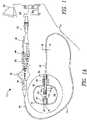
- FIG. 9shows a configuration in which the inner balloon 88 is asymmetrically positioned within the outer balloon 90.
- the proximal neck 96 of the outer balloon 90may be coupled only to an outer surface of the distal portion 22 of the elongate body 18, without being coupled to the proximal neck 94 of the inner balloon 88.
- the portion of interstitial space 92 proximal the proximal necks 94, 96 of the inner 88 and outer 90 balloonsmay be larger than the portion of interstitial space 92 proximate the distal necks 98, 100 of the inner 88 and outer 90 balloons.
- the size of the interstitial space 92 between the proximal necks 94, 96may be determined by the distance between the proximal seal 102 of the inner balloon 88 and the proximal seal 112 of the outer balloon 90.
- the continuously arcuate configuration of the distal portion of the medical devicegenerally provides the ability to deliver therapeutic treatment more precisely, because of the absence of a protruding distal tip enhances ease of navigating the device.
- shape and seal characteristics of the balloonsallow for a more even distribution of pressure exerted by the cryogenic fluid. Balloons with outward seals often experience delamination and bursting because all the pressure exerted within the balloon is pushing outward, essentially pulling the balloon away from the medical device.
- the seals of balloons as presented hereinare strengthened with increased pressure because the cryogenic fluid, as it is expelled in an outward direction and deflected from the balloon surface within the chamber of the balloon, presses against the inverted necks and reinforces the seals.
Landscapes
- Health & Medical Sciences (AREA)
- Life Sciences & Earth Sciences (AREA)
- Surgery (AREA)
- Engineering & Computer Science (AREA)
- Heart & Thoracic Surgery (AREA)
- Nuclear Medicine, Radiotherapy & Molecular Imaging (AREA)
- General Health & Medical Sciences (AREA)
- Veterinary Medicine (AREA)
- Public Health (AREA)
- Biomedical Technology (AREA)
- Animal Behavior & Ethology (AREA)
- Otolaryngology (AREA)
- Medical Informatics (AREA)
- Molecular Biology (AREA)
- Cardiology (AREA)
- Physics & Mathematics (AREA)
- Plasma & Fusion (AREA)
- Child & Adolescent Psychology (AREA)
- Biophysics (AREA)
- Pulmonology (AREA)
- Anesthesiology (AREA)
- Hematology (AREA)
- Media Introduction/Drainage Providing Device (AREA)
Description
- The present invention provides devices comprising catheters having balloons configured to reduce the distal length of the device and to reduce likelihood of delamination of the balloon from the catheter body.
- Tissue ablation is used in numerous medical procedures to treat a patient. Ablation can be performed to remove undesired tissue such as cancer cells. Ablation procedures may also involve the modification of the tissue without removal, such as to stop electrical propagation through the tissue in patients with an arrhythmia. The ablation is often performed by passing energy, such as electrical energy, through one or more electrodes causing the tissue in contact with the electrodes to heats up to an ablative temperature, but may also be performed by freezing the tissue with the use of a cryoablation catheter.
- Cryoablation catheters typically include an expandable element, such as a balloon, at the distal end. Although there are significant advantages of using balloons for cryoablation techniques, there are often associated disadvantages. First, to provide adequate attachment strength between a balloon and the catheter, the distal end of the balloon is often attached to a device distal tip, which may extend distally beyond the balloon. A balloon catheter with a distal tip can be difficult to position within the body, for example the right or left atrium of the heart. For a cryoablation technique to be effective, the distal end must be articulated with great accuracy to contact the balloon with the target tissue. Additionally, this technique is often performed in a very small space. A catheter with a long distal tip (one that extends past the distal neck of the balloon) or a balloon with extended distal and/or proximal necks can exaggerate steering problems.
- Second, there is the concern that the balloon will burst from the application of pressurized cryofluid within, or the seal between the balloon and the body or shaft of the catheter will come undone (delamination). For the typically shaped catheter balloon, a balloon with a conical or ellipsoidal body and two necks, the outward pressure exerted on the balloon pushes the balloon material away from the catheter body or shaft. Longer necks with more attachment surface area are needed to securely attach the balloon to the catheter and prevent delamination due to the forces of pressure. This, in turn, creates longer balloons at the catheter distal tip that are more difficult to steer and precisely contact with target tissue.
US2005203597 discloses a catheter for treating arrhythmia comprising a catheter shaft of a double-cylinder structure where an inner shaft is slidably inserted in an outer shaft, a balloon installed so as to straddle between the tip portion of the inner shaft and the tip portion of the outer shaft, a pair of high frequency current-carrying electrodes of which at least one electrode is provided inside the balloon, and a temperature sensor for monitoring the temperature in the balloon.US2010241070 discloses a balloon catheter that may include a catheter shaft having a proximal end and a distal end, the catheter shaft having a core having an outer surface, the core extending to the distal end of the catheter shaft, the catheter shaft having a tubular member disposed about the core, the tubular member having an inner surface and an outer surface, and an inflation lumen between the tubular member inner surface and the tubular member outer surface, and an inflatable member having a proximal cone, a distal cone and a central section therebetween, the proximal and distal cones defining an inflation cavity, the inflatable member further comprising a proximal waist affixing the proximal cone to the outer surface of the tubular member and a distal waist affixing the distal cone to the outer surface of the core.US 2011/152762 discloses a similar arrangement.- In light of the above, it is the object of the present invention to provide a cryoablation catheter with a shortened distal tip that not only is more easily manipulated within small spaces, but that also includes a balloon that is more resistant to delamination from the catheter body or shaft by making use of the balloon pressure to help reduce the tensile stress on the sealing or bonding agent. Currently used devices with balloons having everted necks experience the opposite effect, with the balloon pressure contributing to delamination. Additionally, glue joints are not particularly good at resisting tensile stress, unless in compression. It is another object to provide a method of using a cryoablation catheter with a shortened distal tip.
- The present invention advantageously provides a medical device as claimed in claim 1.
- A medical device for thermally affecting tissue includes an elongate body, a shaft that is movably disposed within the elongate body, a first balloon disposed within a second balloon, each balloon defining a chamber and having at least one proximal adhesive junction and at least one distal adhesive junction, the second balloon when expanded defining a substantially continuous surface with the distal end of the shaft. The at least one distal adhesive junction of the first balloon may be between the first balloon and the shaft and extend within the chamber of the first balloon, and the at least one distal adhesive junction of the second balloon may be between the second balloon and the first balloon and extend within the chamber of the first balloon. The first balloon may be asymmetrically positioned within the second balloon, with the at least one proximal adhesive junction of the first balloon being one proximal adhesive junction between the first balloon and the elongate body and extending within the chamber of the first balloon, and the at least one proximal adhesive junction of the second balloon being one proximal adhesive junction between the second balloon and the elongate body and extending proximally along the elongate body external to the chamber of the first balloon. The proximal adhesive junction of the first balloon may be located a distance along the elongate body from the proximal adhesive junction of the second balloon, the distance defining an interstitial space between the first balloon and the second balloon. Further, the at least one distal adhesive junction of the first balloon may define a length that is greater than the length defined by the at least one distal adhesive junction of the second balloon. Alternatively, the first balloon may be symmetrically positioned within the second balloon, with the at least one proximal adhesive junction of the first balloon including an adhesive junction between the first balloon and the elongate body and the second balloon, the at least one proximal adhesive junction of the first balloon and the at least one adhesive junction of the second balloon both extending within the chamber of the first balloon. Alternatively, the first balloon may be symmetrically positioned within the second balloon, the at least one proximal adhesive junction of the first balloon being one proximal adhesive junction between the first balloon and the elongate body and extending within the chamber of the first balloon, and the at least one proximal adhesive junction of the second balloon being one proximal adhesive junction between the second balloon and the elongate body and extending proximally along the elongate body external to the chamber of the first balloon. The at least one distal adhesive junction and the at least one proximal adhesive junction of the first balloon may extend within the chamber of the first balloon each define a length of approximately 10% to 30% of the total inflated balloon length. Further, the second balloon defines a distal face when inflated, and the shaft is coterminous with the distal face. The first, inner balloon may have a distal neck coupled to the distal portion of the shaft to form a distal seal that is substantially coterminous with the distal portion of the shaft; there may be a fluid injection conduit disposed within the chamber of the first balloon; the first balloon being symmetrically positioned within the second balloon, with the proximal seal of the first balloon comprising an adhesive junction between the first balloon and the distal portion of the catheter body and extending within the chamber of the first balloon, and the proximal seal of the second balloon comprising an adhesive junction between the second balloon and the distal portion of the catheter body at a distance proximal to the proximal seal of the first balloon, the proximal seal of the second balloon extending externally to the chamber of the first balloon; the at least one distal seal of the first balloon comprising an adhesive junction between the first balloon and the distal portion of the shaft and also comprising an adhesive junction between the first and second balloons, the distal seal of the first balloon extending within the chamber of the first balloon; and the proximal seal and the distal seal of the first balloon each defining a length of approximately 10% to 30% of the inflated balloon length. Furthermore, the second balloon defines a distal face when inflated, the shaft being coterminous with the distal face.
- A more complete understanding of the present invention, and the attendant advantages and features thereof, will be more readily understood by reference to the following detailed description when considered in conjunction with the accompanying drawings. It is noted that the devices illustrated in
figures 1-5 are not a part of the inventions and are shown for illustriative purposes only. FIG. 1A is an illustration of a generalized medical system constructed in accordance with the principles of the present disclosure;FIG. 1B is a cross-sectional view of the elongate body of a medical device;FIG. 2 is a perspective view of a first example of a medical device, in which both the proximal and distal necks are inverted;FIG. 3 is a perspective view of a second example of a medical device, in which the proximal neck is everted and the distal neck is inverted;FIG. 4 is a cross-sectional view of the first example of the medical device ofFIG. 2 , in which the both the proximal and distal necks are inverted;FIG. 5 is a cross-sectional view of the second example of the medical device ofFIG. 3 , in which the proximal neck is everted and the distal neck is inverted;FIG. 6 is a cross-sectional view of a first embodiment of a medical device, the device having two balloons with a first balloon symmetrically positioned within a second balloon and the proximal and distal necks of both balloons being inverted;FIG. 7 is a cross-sectional view of a second embodiment of a medical device, the device having two balloons with a first balloon asymmetrically positioned within a second balloon and the proximal and distal necks of both balloons being inverted;FIG. 8 is an illustration of a cross-sectional view of a third embodiment of a medical device, the device having two balloons with a first balloon symmetrically positioned within a second balloon and the distal necks of both balloons being inverted, the proximal neck of the first balloon being inverted, and the proximal neck of the second balloon being everted; andFIG. 9 is a cross-sectional view of a fourth embodiment of a medical device, the device having two balloons with a first balloon asymmetrically positioned within a second balloon and the distal necks of both balloons being inverted, the proximal neck of the first balloon being inverted, and the proximal neck of the second balloon being everted.- The present disclosure provides a medical system, specifically, a balloon catheter, that is more easily navigated within the body of a patient and that includes a balloon that is more resistant to bursting and delamination. Referring now to the drawing figures in which like reference designations refer to like elements, an embodiment of a medical system constructed in accordance with principles of the disclosure is shown in
FIG. 1A and generally designated as "10." Thesystem 10 generally includes amedical device 12 that may be coupled to acontrol unit 14 or operating console. Themedical device 12 may generally include one or more treatment regions, including at least oneballoon 16, for energetic or other therapeutic interaction between themedical device 12 and a treatment site. The treatment region(s) may deliver, for example, cryogenic therapy, radiofrequency energy, or other energetic transfer with a tissue area in proximity to the treatment region(s), including cardiac tissue. - The
medical device 12 may include anelongate body 18 passable through a patient's vasculature and/or proximate to a tissue region for diagnosis or treatment, such as a catheter, sheath, or intravascular introducer. Theelongate body 18 may define aproximal portion 20 and adistal portion 22, and may further include one or more lumens disposed within theelongate body 18 thereby providing mechanical, electrical, and/or fluid communication between the proximal portion of theelongate body 18 and the distal portion of theelongate body 18, as discussed in more detail below. - The
medical device 12 may include a rigid orsemi-rigid shaft 24 at least partially disposed within a portion of theelongate body 18. Theshaft 24 may extend or otherwise protrude from a distal end of theelongate body 18, and may be movable with respect to theelongate body 18 in longitudinal and rotational directions. That is, theshaft 24 may be slidably and/or rotatably moveable with respect to theelongate body 18. Theshaft 24 may further define alumen 26 therein for the introduction and passage of a guide wire. Theshaft 24 may comprise a plurality of sections, each section having a varying diameter, with the shaft terminating in or otherwise including an area having a larger diameter than the rest of theshaft 24, which may be referred to as adistal tip 28. Thedistal tip 28 may define an opening and passage therethrough that is in communication with theshaft lumen 26. As discussed in greater detail below, theballoon 16 may be attached to thedistal tip 28. However, it will be understood that theshaft 24 may have a single continuous diameter with theballoon 16 being attached to the shaft proximate the distal end of the shaft. - The
medical device 12 may further include afluid delivery conduit 30 traversing at least a portion of theelongate body 18 and towards thedistal portion 22. Thedelivery conduit 30 may be coupled to or otherwise extend from thedistal portion 22 of theelongate body 18 into theballoon 16. Thedelivery conduit 30 may, for example, be wrapped or coiled about at least a portion of theshaft 24 within the balloon, as shown inFIG. 1A . Alternatively, thedelivery conduit 30 may be otherwise coupled to theshaft 24 of themedical device 12, or may be disposed within theshaft 24 with the shaft defining one or more openings through which fluid may pass into the balloon (for example, as shown inFIG. 4 ). Alternatively, thefluid delivery conduit 30 may be flexible, constructed from a shape memory material (such as Nitinol), and/or include other controllably deformable materials that allow thefluid delivery conduit 30 to be manipulated into a plurality of different geometric configurations, shapes, and/or dimensions. Although a fluid delivery conduit is not expressly shown inFIGS. 5-9 for simplicity, it will be understood that the devices shown in all figures may have any suitable, fluid delivery conduit including those shown inFIGS. 1A and4 . - The
fluid delivery conduit 30 may define a lumen therein for the passage or delivery of a fluid from the proximal portion of theelongate body 18 and/or thecontrol unit 14 to the distal portion and/or treatment region of themedical device 12. Thefluid delivery conduit 30 may further include one or more apertures or openings therein to provide for the dispersion or directed ejection of fluid from the lumen to theinterior chamber 34 of theballoon 16. - The
medical device 12 may further include ahandle 44 coupled to theproximal portion 20 of theelongate body 18. Thehandle 44 can include circuitry for identification and/or use in controlling of themedical device 12 or another component of thesystem 10. For example, thehandle 44 may include one ormore pressure sensors 46 to monitor the fluid pressure within themedical device 12. Additionally, thehandle 44 may be provided with a fitting 48 for receiving a guide wire that may be passed into theguide wire lumen 26. Thehandle 44 may also includeconnectors 50 that are matable directly to a fluid supply/exhaust andcontrol unit 14 or indirectly by way of one or more umbilicals. Thehandle 44 may further include blood detection circuitry in fluid and/or optical communication with the injection, exhaust and/or interstitial lumens. Thehandle 44 may also include a pressure relief valve in fluid communication with thefluid delivery conduit 30 and/or exhaust lumen to automatically open under a predetermined threshold value in the event that value is exceeded. - The
handle 44 may also include one or more actuation or control features that allow a user to control, deflect, steer, or otherwise manipulate a distal portion of the medical device from the proximal portion of the medical device. For example, thehandle 44 may include one or more components such as a lever orknob 52 for manipulating theelongate body 18 and/or additional components of themedical device 12. For example, a pull wire with a proximal end and a distal end may have its distal end anchored to theelongate body 18 at or near thedistal portion 22. A proximal end of thepull wire 54 may be anchored to an element such as a cam in communication with and responsive to thelever 52. A distal end of thepull wire 54 may be attached or coupled to a portion ofelongate body 18 or theshaft 24. As a non-limiting example, thepull wire 54 may be coupled to acoupling element 55 that is, in turn, coupled to the shaft 24 (as shown in the figures). However, it will be understood that thepull wire 54 may be coupled to the device in any manner suitable to create at least one point of inflection (that is, a location at which the device may bend during navigation through the patient's vasculature) in a desired location on theelongate body 18 and/or the treatment element. Themedical device 12 may include anactuator element 56 that is movably coupled to the proximal portion of theelongate body 18 and/or thehandle 44. Theactuator element 56 may further be coupled to a proximal portion of theshaft 24 such that manipulating theactuator element 56 in a longitudinal direction causes theshaft 24 to slide towards either of the proximal or distal portions of theelongate body 18. Theactuator element 56 may include a thumb-slide, a push-button, a rotating lever, or other mechanical structure for providing a movable coupling to theelongate body 18, thehandle 44, and/or theshaft 24. Moreover, theactuator element 56 may be movably coupled to thehandle 44 such that the actuator element is movable into individual, distinct positions, and is able to be releasably secured in any one of the distinct positions. Thehandle 44 may also include one or more rotational actuator elements for rotating theshaft 24 and/or a guide wire. - The
control unit 14 may include one ormore computers 58 that include one or more processors for receiving signals from one or more sensors throughout thesystem 10, and or for the automatic, semi-automatic, and/or manual operation of the system. For example, thesystem 10 may include one ormore computers 58 having one or more user input devices by which a user can program system parameters such as the inflation and deflation of a balloon, circulation of coolant through the fluid delivery and recovery conduits, and/or the operation of one or more electrodes or other thermal delivery elements. Additionally, the user may use the user input devices to override the automatic operation of thesystem 10 either programmed into or predetermined by thecontrol unit 14. - The
system 10 may further include one or more sensors to monitor the operating parameters throughout the system, including for example, pressure, temperature, flow rates, volume, or the like in thecontrol unit 14 and/or themedical device 12, in addition to monitoring, recording or otherwise conveying measurements or conditions within themedical device 12 or the ambient environment at the distal portion of themedical device 12. The sensor(s) may be in communication with thecontrol unit 14 for initiating or triggering one or more alerts or therapeutic delivery modifications during operation of themedical device 12. One or more valves, controllers, or the like may be in communication with the sensor(s) to provide for the controlled dispersion or circulation of fluid through the lumens/fluid paths of themedical device 12. Such valves, controllers, or the like may be located in a portion of themedical device 12 and/or in thecontrol unit 14. - In an exemplary system, a
fluid supply 60 including a coolant, cryogenic refrigerant, or the like, an exhaust or scavenging system for recovering or venting expended fluid for re-use or disposal, as well as various control mechanisms for the medical system may be housed in thecontrol unit 14. In addition to providing an exhaust function for the catheter fluid supply, the console may also include pumps, valves, controllers or the like to recover and/or re-circulate fluid delivered to the handle, the elongate body, and/or the fluid pathways of themedical device 12. Avacuum pump 62 in thecontrol unit 14 may create a low-pressure environment in one or more conduits within themedical device 12 so that fluid is drawn into the conduit(s)/lumen(s) of theelongate body 18, away from the distal portion and towards the proximal portion of theelongate body 18. For example, thecontrol unit 14 may include afluid recovery reservoir 64 that is in fluid communication with afluid recovery conduit 66 that is, in turn, in fluid communication with theballoon 16. Thecontrol unit 14 may include one or more controllers, processors, and/or software modules containing instructions or algorithms to provide for the automated operation and performance of the features, sequences, or procedures described herein. - While the
medical device 12 may be in fluid communication with a cryogenic fluid source to cryogenically treat selected tissue, it is also contemplated that themedical device 12 may alternatively or additionally include one or more electrically conductive portions or electrodes thereon coupled to a radiofrequency generator or power source as a treatment or diagnostic mechanism. - Referring now to
FIG. 1B , a non-limiting cross-sectional view of theelongate body 18 of the device is shown. Theelongate body 18 may generally include aninner lumen 67, one or morepull wire lumens 68, and, optionally, one or moreouter lumens 70. Theinner lumen 67 may be sheathed by or defined by a layer of braided wire and/or a layer of Teflon (not shown for simplicity). Thesheath 24 andfluid delivery conduit 30 may be disposed within theinner lumen 67, and the space within theinner lumen 67 surrounding thesheath 24 may be in communication with thevacuum 62 for the removal of expanded coolant from the distal end of the device. One ormore pull wires 54 may be located within the one or morepull wire lumens 68 on the outside of theinner lumen 67, although thepull wire 54 is shown inFIGS. 1A and4-9 The one or moreouter lumens 70 may serve as conduits for additional fluids, wires, sensors, or the like. However, it will be understood that other suitable configurations of interior components and lumens may also be used. - Referring now to
FIGS. 1A through 9 , at least oneballoon 16 may be at the distal portion of themedical device 12. The at least oneballoon 16 may be coupled to a portion of theelongate body 18 and also coupled to a portion of theshaft 24 to contain a portion of thefluid delivery conduit 30 therein, as shown and discussed in more detail inFIGS. 2-9 . Eachballoon 16 may each define an interior chamber orregion 34. For example, coolant or fluid dispersed from thefluid delivery conduit 30 may circulate within theinterior chamber 34, and theinterior chamber 34 may be in fluid communication with thefluid recovery conduit 66 defined by or included in theelongate body 18 for the removal of dispersed coolant from theinterior chamber 34 of theballoon 16. In embodiments in which thedevice 12 includes more than one balloon, an additional fluid delivery conduit and/or fluid recovery conduit may fluidly connect the additional balloons to thecontrol unit 14. The at least oneballoon 16 may further include one or more material layers providing for puncture resistance, radiopacity, or the like. - As shown in
FIGS 2-9 , the distal end of theshaft 24, for example, thedistal tip 28, is rounded to match the curvature of aballoon 16 when inflated, such that theballoon 16 defines adistal face 72 having a substantially continuous surface, without theshaft 24 protruding beyond the balloondistal face 72. Further, thedistal tip 28 or distal end of theshaft 24 is manufactured with a curved distal surface that matches a curve in the balloondistal face 72, enhancing the continuity between theshaft 24 and thedistal face 72. The shaft is depicted inFIGS. 2 and3 as "24/28" to include embodiments in which theballoon 16 is generally coupled to the distal portion of theshaft 24 and embodiments in which theballoon 16 is coupled to adistal tip 28 in particular. Thedistal face 72 is slightly curved or arcuate, creating an atraumatic surface for safe navigation through the patient's vasculature and within the patient's heart. A substantially continuous arcuate surface without any projections facilitates steering of the distal end of the medical device within the patient, especially in small spaces such as the chambers of the heart or vasculature. Although the balloon is shown in the figures as having a substantially spherical or rounded cubic shape, it will be understood that the balloon may have any suitable shape that allows for the inclusion of a shortened distal tip. - The
medical device 12 may include asingle balloon 16, as seen inFIGS. 4 and5 ; this device, however, is not claimed. Theballoon 16 may have aproximal neck 80 at which theballoon 16 is coupled, by an adhesive junction or other joining means, to thedistal portion 22 of theelongate body 18, and may further have adistal neck 82 at which theballoon 16 is coupled, by an adhesive junction or other joining means, to a distal portion of theshaft 24, such as thedistal tip 28. Thedistal neck 80 of theballoon 16 may be turned inward (in a distal-to-proximal direction) extending within thechamber 34 of theballoon 16. This may be referred to as thedistal neck 80 being inverted. The inward extension of thedistal neck 80 may form adistal seal 84 that is substantially coterminous with theshaft 24, and may define a length of approximately 10% to 30% of the total length of theballoon 16 when the balloon is in an inflated state. The length of the inflated and uninflated balloon may be measured as a straightline distance between the proximalmost point and the distalmost point of theballoon 16. In the figures, all seals, which may also be referred to as "adhesive junctions," are stylistically depicted with hash marks for clarity. - As seen in
FIG. 4 , the expandable element may be substantially toroidal in shape, with theproximal neck 80 also being inverted (that is, turned inward, extending in a proximal-to-distal direction). In this configuration, an outer surface of theproximal neck 80 may be bonded, adhered, or otherwise in contact with and attached to an outer surface of thedistal portion 22 of theelongate body 18 to create aproximal seal 86 extending within the ballooninterior chamber 34. Theproximal seal 86 may define a length of approximately 10% to 30% of the total length of theballoon 16 when in an inflated state. Alternatively, as seen inFIG. 5 , theballoon 16 may include aproximal neck 80 that is everted (that is, turned outward, extending in a distal-to-proximal direction). In this configuration, an inner surface of theproximal neck 80 may be bonded, adhered, or otherwise in contact with and attached to an outer surface of thedistal portion 22 of theelongate body 18 to create aproximal seal 86 extending without (that is, being external to) the ballooninterior chamber 34 along an outer surface of thedistal portion 22 of theelongate body 18. Further, theproximal neck 80 may be coupled to thedistal portion 22 of theelongate body 18 such that the proximal neck 80 (proximate the balloon chamber 34) and theelongate body 18 are coterminous (for example, as shown inFIG. 4 ), or theproximal neck 80 may be coupled to thedistal portion 22 of theelongate body 18 such that a portion of theelongate body 18 extends within the chamber 34 (for example, as shown inFIG. 5 ). In all embodiments, theballoon 16 may define adistal face 72 that has a substantially continuous surface that facilitates navigation of the device within the patient. - The
medical device 12 includes two balloons.FIGS. 6-9 show amedical device 12 having aninner balloon 88 and anouter balloon 90. The inner 88 and outer 90 balloons together may comprise thetreatment element 91. Theinner balloon 88 may contain a portion of thefluid delivery conduit 30 therein, and theouter balloon 90 may be disposed about theinner balloon 88. The inner 88 and outer 90 balloons inFIGS. 6-9 may be substantially similar to thesingle balloon 16 shown and described in the other figures, in composition, function, attachment, etc. The inner 88 and outer 90 balloons may be located substantially adjacent to or in contact with each other, and may define aninterstitial space 92 between theballoons FIGS.6 and8 , theinterstitial space 92 may be very thin, even absent in some areas, especially when theinner balloon 88 is inflated and in contact with theouter balloon 90. In the embodiments shown inFIGS. 7 and9 , however, theinterstitial space 92 may be larger in at least a portion of the treatment element. The two-balloon configuration adds strength to the treatment element, in that a delamination force resulting from inflation of theinner balloon 88 would have to overcome the seals of both the inner and outer balloons for thetreatment element 91 to delaminate. - As shown in
FIGS. 6-9 , each of the inner 88 and outer 90 balloons have aproximal neck distal portion 22 of theelongate body 18, and adistal neck shaft 24, for example, thedistal tip 28. In all ofFIGS. 6-9 , theouter balloon 90 defines adistal face 72 that has a substantially continuous surface that facilitates navigation of the device within the patient. Theshaft 24 ordistal tip 28 is substantially coterminous with thedistal balloon 90. - Continuing to refer to
FIGS. 6-9 , theinner balloon 88 may be substantially toroidal in shape, with theproximal neck 94 being inverted (that is, turned inward, in a proximal-to-distal direction) to form a firstproximal seal 102 between an outer surface of theproximal neck 94 and an outer surface of thedistal portion 22 of theelongate body 18, and thedistal neck 98 being inverted (that is, turned inward, in a distal-to-proximal direction) to form a firstdistal seal 104 between an outer surface of thedistal neck 98 and a distal portion of the shaft 24 (for example, the distal tip 28), eachseal interior chamber 34 of theinner balloon 88. Although theseals second balloon 90, the description is limited to extension within theinterior chamber 34 of theinner balloon 88 for simplicity of reference. As is discussed in more detail below, the firstproximal seal 102 and the firstdistal seal 104 of theinner balloon 88 may be attached to theelongate body 18 andshaft 24, respectively. A second portion of eachneck outer balloon 90. As such, fluid leaking from theinner balloon 88 may more easily flow between the inner 88 and outer 90 balloons for detection by a leak-detection sensor disposed in theinterstitial space 92, such as a pressure or impedance sensor. Thedistal neck 98 andproximal neck 94 of theinner balloon 88 may each define a length of approximately 10% to 30% of the total length of theinner balloon 88 when theinner balloon 88 is in an inflated state, with the length of eachneck inner balloon 88. - The
distal neck 100 of theouter balloon 90 may also be inverted (that is, turned inward, in a distal-to-proximal direction), extending within theinterior chamber 34 of theinner balloon 88. An outer surface of thedistal neck 100 of theouter balloon 90 may be bonded, adhered, or otherwise in contact with and attached to an outer surface of a distal portion of the shaft 24 (for example, the distal tip 28) to create adistal seal 110 extending within theinterior chamber 34 of theinner balloon 88. An inner surface ofdistal neck 100 of theouter balloon 90 may also be in contact with or substantially in contact with, but not attached to, an outer surface of thedistal neck 98 of theinner balloon 88. At least a portion of thedistal neck 98 of theinner balloon 88 may overlap the inverteddistal neck 100 of theouter balloon 90. - Now referring in particular to
FIGS. 6 and7 , theproximal neck 96 of theouter balloon 90 may also be inverted (that is, turned inward, in a proximal-to-distal direction), extending within theinterior chamber 34 of theinner balloon 88. An outer surface of the outer balloonproximal neck 96 may be bonded, adhered, or otherwise in contact with and attached to an outer surface to thedistal portion 22 of theelongate body 18 to form aproximal seal 112. Theinner balloon 88 may be symmetrically or asymmetrically positioned within theouter balloon 90, depending on, for example, the desired maneuverability of the device, the procedure for which the device is used, and/or the desired cooling effect of the treatment element. For example, the device shown inFIG. 6 may have a more distal deflection point than the device shown inFIG. 7 , because the layeredproximal necks proximal necks elongate body 18. This more distal deflection point may allow the device to be navigated through tortuous vasculature more easily. Additionally, the asymmetrical configuration shown inFIG. 7 may affect the cooling capacity of thetreatment element 91. The largerinterstitial space 92 between the inner 88 and outer 90 balloons may provide thermal insulation of theinner balloon 88, particularly the proximal portion of theinner balloon 88, from the warming effect of the surrounding blood. This, in turn, may enhance the cooling effect of, at least, the distal portion of the treatment element through theouter balloon 90. That is, the limited heat transfer from tissue to the proximal portion of theinner balloon 88 may preserve and potentially concentrated the cooling capacity within the distal portion of thetreatment element 91.. The symmetrical configuration shown inFIG. 6 may allow cooling of both the proximal and distal portions of thetreatment element 91. In a non-limiting embodiment, this symmetrical configuration may be useful when the device is inserted into the left atrium through a pulmonary vein, and then retracted so that the proximal portion of thetreatment element 91 is in contact with the pulmonary vein ostium. In that case, the proximal portion, rather than the distal portion, of thetreatment element 91 may be used to thermally treat the pulmonary vein ostium. FIG. 6 shows a configuration in which theinner balloon 88 is symmetrically positioned within, and concentric with, theouter balloon 90. Both the inner 88 and outer 90 balloons inFIG. 6 may be toroidal in shape, with theproximal necks distal necks interior chamber 34 of theinner balloon 88. In such an embodiment, an inner surface of theproximal neck 96 of theouter balloon 90 may be in contact with or substantially in contact with, but not attached to, an outer surface of theproximal neck 94 of theinner balloon 88. At least a portion of theproximal neck 94 of theinner balloon 88 may overlap theproximal neck 96 of theouter balloon 90. In this manner, a double-layered adhesive junction may be formed, which may further prevent delamination or tearing from occurring when the balloons are inflated and burst pressure is exerted.FIG. 7 shows a configuration in which theinner balloon 88 may be asymmetrically positioned within theouter balloon 90. Both the inner 88 and outer 90 balloons may be toroidal in shape, but may not be concentric, unlike the configuration shown inFIG. 6 . In the configuration shown inFIG. 7 , theproximal neck 96 of theouter balloon 90 may be bonded, adhered, or otherwise in contact with and attached only to thedistal portion 22 of theelongate body 18, without being overlapped by and coupled to at least a portion of theproximal neck 94 of theinner balloon 88. Further, theproximal neck 96 of theouter balloon 90 may not extend within theinterior chamber 34 of theinner balloon 88, but may instead extend within theinterstitial space 92 between the inner 88 and outer 90 balloons. Defined another way, theproximal neck 96 of theouter balloon 90 may be inverted within thetreatment element 91 as a whole. As shown inFIG. 7 , the portion ofinterstitial space 92 proximate theproximal necks interstitial space 92 proximate thedistal necks interstitial space 92 proximal theproximal necks proximal seal 102 of theinner balloon 88 and theproximal seal 112 of theouter balloon 90.- Referring now to
FIGS. 8 and9 , theproximal neck 96 of theouter balloon 90 may be everted (that is, turned outward, in a distal-to-proximal direction), extending without or being external to both theinterior chamber 34 of theinner balloon 88 and theinterstitial space 92 between the inner 88 andouter balloons 90. Defined another way, theproximal neck 96 of theouter balloon 90 may be everted on the outside of thetreatment element 91 as a whole. An inner surface of theproximal neck 96 of theouter balloon 90 may be bonded, adhered, or otherwise in contact with and attached to thedistal portion 22 of theelongate body 18 to form a firstproximal seal 112. Theinner balloon 88 may be symmetrically or asymmetrically positioned within theouter balloon 90, with the advantages of each configuration being as discussed above regardingFIGS. 6 and7 . FIG. 8 shows a configuration in which theinner balloon 88 is symmetrically positioned within, and concentric with, theouter balloon 90. In such an embodiment, theproximal neck 96 of theouter balloon 90 may not be coupled to theproximal neck 94 of theinner balloon 88, but theproximal seal 112 of theouter balloon 90 and theproximal seal 102 of theinner balloon 88 may be substantially adjacent to each other, extending in opposite directions. For example, as shown inFIG. 8 , theproximal seal 112 of theouter balloon 90 may extend be everted (that is, external to the treatment element 91) in a distal-to-proximal direction, and theproximal seal 102 of theinner balloon 88 may be inverted and extend within the interior chamber 88 (and thetreatment element 91 as a whole) in a proximal-to-distal direction. Theinterstitial space 92 defined between the inner 88 and outer 90 balloons may only be wide enough to facilitate leak detection or leak containment within theouter balloon 90.FIG. 9 shows a configuration in which theinner balloon 88 is asymmetrically positioned within theouter balloon 90. In such an embodiment, theproximal neck 96 of theouter balloon 90 may be coupled only to an outer surface of thedistal portion 22 of theelongate body 18, without being coupled to theproximal neck 94 of theinner balloon 88. As shown inFIG. 9 , the portion ofinterstitial space 92 proximal theproximal necks interstitial space 92 proximate thedistal necks interstitial space 92 between theproximal necks proximal seal 102 of theinner balloon 88 and theproximal seal 112 of theouter balloon 90.- The continuously arcuate configuration of the distal portion of the medical device generally provides the ability to deliver therapeutic treatment more precisely, because of the absence of a protruding distal tip enhances ease of navigating the device. Further, shape and seal characteristics of the balloons allow for a more even distribution of pressure exerted by the cryogenic fluid. Balloons with outward seals often experience delamination and bursting because all the pressure exerted within the balloon is pushing outward, essentially pulling the balloon away from the medical device. In contrast, the seals of balloons as presented herein are strengthened with increased pressure because the cryogenic fluid, as it is expelled in an outward direction and deflected from the balloon surface within the chamber of the balloon, presses against the inverted necks and reinforces the seals. Although not expressly shown, it will be understood that a configuration may be presented in which the
distal necks proximal necks FIGS. 6-9 ). - The invention is defined in the following claims. Other embodiments, examples, equivalents and, in particular, surgical methods, are not a part of the invention.
Claims (12)
- A medical device (12) for thermally affecting tissue comprising:an elongate body (18);a shaft (24) disposed within the elongate body, the shaft including a distalmost end face (28);a first expandable element (16; 91) coupled to the elongate body and defining a chamber (34) therein and having a curvature when the first expandable element is expanded, the first expandable element having a proximal neck (80; 94, 96) coupled to the elongate body and forming a proximal seal (86; 112), the first expandable element further having a distal neck (82; 98, 100) coupled to the shaft at a location that is immediately proximate the distalmost end face of the shaft and forming a distal seal (84; 110) substantially coterminous with the shaft, the distal seal extending within the chamber of the first expandable element; whereinthe proximal neck and the distal neck each include an outer surface and an inner surface, the proximal seal is formed between the outer or inner surface of the proximal neck and a distal portion (22) of the elongate body,characterised in that:the distalmost end face (28) of the shaft being curved to match the curvature of a distal face (72) of the first expandable element such that the first expandable element defines the distal face with a substantially continuous surface; andthe device further includes a second expandable element (88) disposed within the first expandable element (90).
- The medical device of Claim 1, the distal seal being formed between the outer surface of the distal neck and a distal portion of the shaft.
- The medical device of Claim 2, wherein the proximal seal extends within the chamber of the first expandable element.
- The medical device of Claim 1, wherein the proximal seal is external to the chamber of the first expandable element and extends along the elongate body in a proximal direction from the chamber of the first expandable element.
- The medical device of Claim 4, further including a fluid injection conduit (30) in fluid communication with a coolant reservoir (60).
- The medical device of Claim 4, wherein the proximal seal and the distal seal each define a length of 10% to 30% of the total length of the first expandable element when the first expandable element is inflated.
- The medical device of Claim 4, wherein the distal seal defines a length of 10% to 30% of the total length of the first expandable element when the first expandable element is inflated.
- The medical device of Claim 1, wherein the second expandable element (88) defines a distal seal (104) with the shaft and a proximal seal (102) with the elongate body, and the distal seal of the second expandable element extends within the chamber of the second expandable element.
- The medical device of Claim 8, wherein the proximal seal (112) of the first expandable element is located a distance from the proximal seal (102) of the second expandable element, the distance defining an interstitial space (92) between the first expandable element and the second expandable element.
- The medical device of Claim 9, wherein the distal seal of the second expandable element defines a length that is greater than the length defined by the distal seal of the first expandable element.
- The medical device of Claim 9, wherein the second expandable element is symmetrically positioned within the first expandable element.
- The medical device of Claim 9, wherein the second expandable element is asymmetrically positioned within the first expandable element.
Priority Applications (1)
| Application Number | Priority Date | Filing Date | Title |
|---|---|---|---|
| EP22202024.0AEP4186452A1 (en) | 2014-03-21 | 2015-03-18 | Balloon design to reduce distal length |
Applications Claiming Priority (2)
| Application Number | Priority Date | Filing Date | Title |
|---|---|---|---|
| US14/221,763US9925359B2 (en) | 2014-03-21 | 2014-03-21 | Balloon design to reduce distal length |
| PCT/CA2015/000166WO2015139117A1 (en) | 2014-03-21 | 2015-03-18 | Balloon design to reduce distal length |
Related Child Applications (2)
| Application Number | Title | Priority Date | Filing Date |
|---|---|---|---|
| EP22202024.0ADivision-IntoEP4186452A1 (en) | 2014-03-21 | 2015-03-18 | Balloon design to reduce distal length |
| EP22202024.0ADivisionEP4186452A1 (en) | 2014-03-21 | 2015-03-18 | Balloon design to reduce distal length |
Publications (3)
| Publication Number | Publication Date |
|---|---|
| EP3119302A1 EP3119302A1 (en) | 2017-01-25 |
| EP3119302A4 EP3119302A4 (en) | 2018-02-14 |
| EP3119302B1true EP3119302B1 (en) | 2022-11-30 |
Family
ID=54141089
Family Applications (2)
| Application Number | Title | Priority Date | Filing Date |
|---|---|---|---|
| EP15764253.9AActiveEP3119302B1 (en) | 2014-03-21 | 2015-03-18 | Balloon design to reduce distal length |
| EP22202024.0AWithdrawnEP4186452A1 (en) | 2014-03-21 | 2015-03-18 | Balloon design to reduce distal length |
Family Applications After (1)
| Application Number | Title | Priority Date | Filing Date |
|---|---|---|---|
| EP22202024.0AWithdrawnEP4186452A1 (en) | 2014-03-21 | 2015-03-18 | Balloon design to reduce distal length |
Country Status (5)
| Country | Link |
|---|---|
| US (3) | US9925359B2 (en) |
| EP (2) | EP3119302B1 (en) |
| CN (1) | CN106456232B (en) |
| CA (1) | CA2942896C (en) |
| WO (1) | WO2015139117A1 (en) |
Families Citing this family (39)
| Publication number | Priority date | Publication date | Assignee | Title |
|---|---|---|---|---|
| US10695126B2 (en) | 2008-10-06 | 2020-06-30 | Santa Anna Tech Llc | Catheter with a double balloon structure to generate and apply a heated ablative zone to tissue |
| WO2015048806A2 (en) | 2013-09-30 | 2015-04-02 | Nidus Medical, Llc | Apparatus and methods for treating rhinitis |
| US9763743B2 (en) | 2014-07-25 | 2017-09-19 | Arrinex, Inc. | Apparatus and method for treating rhinitis |
| US12268433B2 (en) | 2015-05-12 | 2025-04-08 | National University Of Ireland, Galway | Devices for therapeutic nasal neuromodulation and associated methods and systems |
| WO2016183337A2 (en) | 2015-05-12 | 2016-11-17 | National University Of Ireland Galway | Devices for therapeutic nasal neuromodulation and associated methods and systems |
| EP3413822B1 (en) | 2016-02-11 | 2023-08-30 | Arrinex, Inc. | Device for image guided post-nasal nerve ablation |
| US12364537B2 (en) | 2016-05-02 | 2025-07-22 | Santa Anna Tech Llc | Catheter with a double balloon structure to generate and apply a heated ablative zone to tissue |
| US11331140B2 (en) | 2016-05-19 | 2022-05-17 | Aqua Heart, Inc. | Heated vapor ablation systems and methods for treating cardiac conditions |
| US10905329B2 (en) | 2016-06-09 | 2021-02-02 | Biosense Webster (Israel) Ltd. | Multi-function conducting elements for a catheter |
| CN109600988B (en) | 2016-06-15 | 2021-08-31 | 阿里内克斯股份有限公司 | Devices and methods for treating the lateral surface of the nasal cavity |
| US10939965B1 (en) | 2016-07-20 | 2021-03-09 | Arrinex, Inc. | Devices and methods for treating a nerve of the nasal cavity using image guidance |
| US11253312B2 (en) | 2016-10-17 | 2022-02-22 | Arrinex, Inc. | Integrated nasal nerve detector ablation-apparatus, nasal nerve locator, and methods of use |
| US11400205B2 (en) | 2016-11-23 | 2022-08-02 | Biosense Webster (Israel) Ltd. | Balloon-in-balloon irrigation balloon catheter |
| US20180242821A1 (en)* | 2017-02-28 | 2018-08-30 | Biosense Webster (Israel) Ltd. | Lens in balloon catheter |
| EP3614940B1 (en) | 2017-04-28 | 2024-11-20 | Arrinex, Inc. | Systems for locating blood vessels in the treatment of rhinitis |
| US12029545B2 (en) | 2017-05-30 | 2024-07-09 | Biosense Webster (Israel) Ltd. | Catheter splines as location sensors |
| CN107440781B (en)* | 2017-09-12 | 2020-04-28 | 康沣生物科技(上海)有限公司 | Cryoablation catheter with heat insulation protection at head end |
| US11090101B2 (en)* | 2018-05-02 | 2021-08-17 | Medtronic Cryocath Lp | Soft balloon device and system |
| US12102781B2 (en) | 2018-06-29 | 2024-10-01 | Biosense Webster (Israel) Ltd. | Reinforcement for irrigated electrophysiology balloon catheter with flexible-circuit electrodes |
| US11071585B2 (en) | 2018-09-14 | 2021-07-27 | Biosense Webster (Israel) Ltd. | Systems and methods of ablating cardiac tissue |
| US11547473B2 (en) | 2018-12-11 | 2023-01-10 | Neurent Medical Limited | Systems and methods for therapeutic nasal neuromodulation |
| US10828470B1 (en) | 2019-08-14 | 2020-11-10 | Vasoinnovations Inc. | Apparatus and method for advancing catheters or other medical devices through a lumen |
| US12048820B2 (en) | 2019-08-14 | 2024-07-30 | Vasoinnovations Inc. | Apparatus and method for advancing catheters or other medical devices through a lumen |
| US10792469B1 (en) | 2019-08-14 | 2020-10-06 | Vasoinnovations Inc. | Devices, systems, and methods for delivering catheters or other medical devices to locations within a patients body |
| US12369975B2 (en) | 2019-09-12 | 2025-07-29 | Biosense Webster (Israel) Ltd. | Balloon catheter with force sensor |
| US20210077185A1 (en)* | 2019-09-13 | 2021-03-18 | Biosense Webster (Israel) Ltd. | Seals and reinforcement for irrigated electrophysiology balloon catheter with flexible-circuit electrodes |
| US11633228B2 (en) | 2019-10-04 | 2023-04-25 | Biosense Webster (Israel) Ltd. | Identifying pulmonary vein occlusion by dimension deformations of balloon catheter |
| US12369974B2 (en) | 2019-10-10 | 2025-07-29 | Biosense Webster (Israel) Ltd. | Touch indication of balloon-catheter ablation electrode via balloon surface temperature measurement |
| US12137967B2 (en) | 2019-11-12 | 2024-11-12 | Biosense Webster (Israel) Ltd. | Accurate positioning and shape visualization of balloon catheter ablation tags |
| US11896818B2 (en) | 2020-04-09 | 2024-02-13 | Neurent Medical Limited | Systems and methods for therapeutic nasal treatment |
| WO2021205229A1 (en) | 2020-04-09 | 2021-10-14 | Neurent Medical Limited | Systems and methods for improving sleep with therapeutic nasal treatment |
| US12239364B2 (en) | 2020-10-07 | 2025-03-04 | Biosense Webster (Israel) Ltd. | Printed proximal electrodes of an expandable catheter for use as a common electrode |
| US11974803B2 (en) | 2020-10-12 | 2024-05-07 | Biosense Webster (Israel) Ltd. | Basket catheter with balloon |
| US11957852B2 (en) | 2021-01-14 | 2024-04-16 | Biosense Webster (Israel) Ltd. | Intravascular balloon with slidable central irrigation tube |
| US11849995B2 (en) | 2021-02-18 | 2023-12-26 | Biosense Webster (Israel) Ltd. | Detection of balloon catheter tissue contact using optical measurement |
| CN113318329B (en)* | 2021-07-06 | 2025-09-02 | 上海英诺伟医疗器械股份有限公司 | Double-balloon catheter |
| US12114905B2 (en) | 2021-08-27 | 2024-10-15 | Biosense Webster (Israel) Ltd. | Reinforcement and stress relief for an irrigated electrophysiology balloon catheter with flexible-circuit electrodes |
| US12114907B2 (en)* | 2021-11-01 | 2024-10-15 | Medtronic Cryocath Lp | Percutaneous coiled catheter design for gallbladder cryoablation |
| WO2025073438A1 (en)* | 2023-10-04 | 2025-04-10 | Medtronic Ireland Manufacturing Unlimited Company | Safety mechanism for balloon catheter |
Citations (1)
| Publication number | Priority date | Publication date | Assignee | Title |
|---|---|---|---|---|
| US20110152762A1 (en)* | 2009-12-23 | 2011-06-23 | Hershey Adrienne A | Enteral Feeding Catheter Assembly Incorporating An Indicator |
Family Cites Families (38)
| Publication number | Priority date | Publication date | Assignee | Title |
|---|---|---|---|---|
| US3833004A (en) | 1973-10-26 | 1974-09-03 | American Hospital Supply Corp | Balloon catheter having single ferrule support for balloon bindings |
| US4315512A (en)* | 1980-01-24 | 1982-02-16 | Fogarty Thomas J | Piston extension balloon dilatation catheter apparatus and method |
| US4690844A (en) | 1984-10-26 | 1987-09-01 | Saudagar Abdul S | Method for parting rubber and products formed thereby, and a method of making a blood vessel |
| US5108370A (en) | 1989-10-03 | 1992-04-28 | Paul Walinsky | Perfusion balloon catheter |
| US5766151A (en)* | 1991-07-16 | 1998-06-16 | Heartport, Inc. | Endovascular system for arresting the heart |
| US5571088A (en)* | 1993-07-01 | 1996-11-05 | Boston Scientific Corporation | Ablation catheters |
| US6186978B1 (en)* | 1996-08-07 | 2001-02-13 | Target Therapeutics, Inc. | Braid reinforced infusion catheter with inflatable membrane |
| US5868735A (en)* | 1997-03-06 | 1999-02-09 | Scimed Life Systems, Inc. | Cryoplasty device and method |
| CA2281885C (en) | 1997-04-07 | 2007-10-30 | Cook Urological Inc. | Back-up retention member drainage catheter |
| US6117101A (en) | 1997-07-08 | 2000-09-12 | The Regents Of The University Of California | Circumferential ablation device assembly |
| US5997503A (en) | 1998-02-12 | 1999-12-07 | Ballard Medical Products | Catheter with distally distending balloon |
| US6053913A (en) | 1998-09-10 | 2000-04-25 | Tu; Lily Chen | Rapid exchange stented balloon catheter having ablation capabilities |
| US7780628B1 (en) | 1999-01-11 | 2010-08-24 | Angiodynamics, Inc. | Apparatus and methods for treating congestive heart disease |
| US6468268B1 (en) | 1999-01-25 | 2002-10-22 | Cryocath Technologies Inc. | Cryogenic catheter system |
| US6432102B2 (en)* | 1999-03-15 | 2002-08-13 | Cryovascular Systems, Inc. | Cryosurgical fluid supply |
| US6280412B1 (en) | 1999-06-17 | 2001-08-28 | Scimed Life Systems, Inc. | Stent securement by balloon modification |
| US6575966B2 (en)* | 1999-08-23 | 2003-06-10 | Cryocath Technologies Inc. | Endovascular cryotreatment catheter |
| US6679861B2 (en) | 1999-10-04 | 2004-01-20 | K.K. Vayu | Occlusion catheter for the ascending aorta |
| US6391002B1 (en) | 1999-12-07 | 2002-05-21 | Advanced Cardiovascular Systems, Inc. | Balloon with the variable radial force distribution |
| US6551274B2 (en)* | 2000-02-29 | 2003-04-22 | Biosense Webster, Inc. | Cryoablation catheter with an expandable cooling chamber |
| US6746465B2 (en)* | 2001-12-14 | 2004-06-08 | The Regents Of The University Of California | Catheter based balloon for therapy modification and positioning of tissue |
| TWI235073B (en)* | 2002-08-20 | 2005-07-01 | Toray Industries | Catheter for treating cardiac arrhythmias |
| US7220252B2 (en) | 2003-07-18 | 2007-05-22 | Polyzen, Inc. | Inflatable dual balloon catheter |
| US7727191B2 (en)* | 2005-05-13 | 2010-06-01 | Medtronic Cryocath Lp | Compliant balloon catheter |
| US7442190B2 (en)* | 2005-05-13 | 2008-10-28 | Cryocath Technologies Inc. | Contact assessment of balloon catheters |
| US20070106320A1 (en) | 2005-11-10 | 2007-05-10 | John Blix | Balloon catheter for distal protection compatability |
| US8460240B2 (en) | 2006-08-07 | 2013-06-11 | W. L. Gore & Associates, Inc. | Inflatable toroidal-shaped balloons |
| DE102008056250A1 (en) | 2008-10-07 | 2010-04-15 | Fraunhofer-Gesellschaft zur Förderung der angewandten Forschung e.V. | Device for detecting at least one vital parameter of a person in a motor vehicle and device for monitoring at least one vital parameter of a person in a motor vehicle |
| TWI517833B (en) | 2009-03-31 | 2016-01-21 | 東麗股份有限公司 | Shaft for ablation catheter with balloon and ablation catheter system |
| WO2011036667A1 (en)* | 2009-09-23 | 2011-03-31 | Angioslide Ltd. | Balloon catheter and methods of use thereof |
| US8986293B2 (en) | 2010-01-27 | 2015-03-24 | Medtronic Cryocath Lp | Cryoballoon refrigerant dispersion control |
| WO2011141866A2 (en)* | 2010-05-13 | 2011-11-17 | Noel Elman | Stent devices for support, controlled drug delivery and pain management after vaginal surgery |
| US9539046B2 (en) | 2010-08-03 | 2017-01-10 | Medtronic Cryocath Lp | Cryogenic medical mapping and treatment device |
| US8911434B2 (en)* | 2010-10-22 | 2014-12-16 | Medtronic Cryocath Lp | Balloon catheter with deformable fluid delivery conduit |
| US9220555B2 (en) | 2010-10-28 | 2015-12-29 | Medtronic Ablation Frontiers Llc | Cryo-ablation device with deployable injection tube |
| US9387031B2 (en)* | 2011-07-29 | 2016-07-12 | Medtronic Ablation Frontiers Llc | Mesh-overlayed ablation and mapping device |
| US9750565B2 (en)* | 2011-09-30 | 2017-09-05 | Medtronic Advanced Energy Llc | Electrosurgical balloons |
| US9220556B2 (en) | 2012-01-27 | 2015-12-29 | Medtronic Cryocath Lp | Balloon design to enhance cooling uniformity |
- 2014
- 2014-03-21USUS14/221,763patent/US9925359B2/enactiveActive
- 2015
- 2015-03-18CACA2942896Apatent/CA2942896C/enactiveActive
- 2015-03-18EPEP15764253.9Apatent/EP3119302B1/enactiveActive
- 2015-03-18CNCN201580015096.1Apatent/CN106456232B/enactiveActive
- 2015-03-18WOPCT/CA2015/000166patent/WO2015139117A1/enactiveApplication Filing
- 2015-03-18EPEP22202024.0Apatent/EP4186452A1/ennot_activeWithdrawn
- 2017
- 2017-10-17USUS15/785,957patent/US10898694B2/enactiveActive
- 2020
- 2020-12-18USUS17/126,203patent/US11717651B2/enactiveActive
Patent Citations (1)
| Publication number | Priority date | Publication date | Assignee | Title |
|---|---|---|---|---|
| US20110152762A1 (en)* | 2009-12-23 | 2011-06-23 | Hershey Adrienne A | Enteral Feeding Catheter Assembly Incorporating An Indicator |
Also Published As
| Publication number | Publication date |
|---|---|
| US11717651B2 (en) | 2023-08-08 |
| CN106456232A (en) | 2017-02-22 |
| US20150265812A1 (en) | 2015-09-24 |
| US9925359B2 (en) | 2018-03-27 |
| CN106456232B (en) | 2020-09-29 |
| CA2942896C (en) | 2018-11-27 |
| WO2015139117A1 (en) | 2015-09-24 |
| US10898694B2 (en) | 2021-01-26 |
| US20210106798A1 (en) | 2021-04-15 |
| EP3119302A4 (en) | 2018-02-14 |
| EP3119302A1 (en) | 2017-01-25 |
| US20180036517A1 (en) | 2018-02-08 |
| EP4186452A1 (en) | 2023-05-31 |
| CA2942896A1 (en) | 2015-09-24 |
Similar Documents
| Publication | Publication Date | Title |
|---|---|---|
| US11717651B2 (en) | Balloon design to reduce distal length | |
| US10786296B2 (en) | Shape changing ablation balloon | |
| US11666369B2 (en) | Multifunctional ablation device | |
| US11986231B2 (en) | Multi-lobe balloon for cryoablation | |
| CA2804175C (en) | Device and method for pulmonary vein isolation |
Legal Events
| Date | Code | Title | Description |
|---|---|---|---|
| STAA | Information on the status of an ep patent application or granted ep patent | Free format text:STATUS: THE INTERNATIONAL PUBLICATION HAS BEEN MADE | |
| PUAI | Public reference made under article 153(3) epc to a published international application that has entered the european phase | Free format text:ORIGINAL CODE: 0009012 | |
| STAA | Information on the status of an ep patent application or granted ep patent | Free format text:STATUS: REQUEST FOR EXAMINATION WAS MADE | |
| 17P | Request for examination filed | Effective date:20160914 | |
| AK | Designated contracting states | Kind code of ref document:A1 Designated state(s):AL AT BE BG CH CY CZ DE DK EE ES FI FR GB GR HR HU IE IS IT LI LT LU LV MC MK MT NL NO PL PT RO RS SE SI SK SM TR | |
| AX | Request for extension of the european patent | Extension state:BA ME | |
| DAV | Request for validation of the european patent (deleted) | ||
| DAX | Request for extension of the european patent (deleted) | ||
| RIC1 | Information provided on ipc code assigned before grant | Ipc:A61B 18/02 20060101ALI20170925BHEP Ipc:A61B 18/14 20060101ALI20170925BHEP Ipc:A61M 25/10 20130101ALI20170925BHEP Ipc:A61B 18/00 20060101AFI20170925BHEP | |
| REG | Reference to a national code | Ref country code:DE Ref legal event code:R079 Ref document number:602015081792 Country of ref document:DE Free format text:PREVIOUS MAIN CLASS: A61B0018020000 Ipc:A61B0018000000 | |
| A4 | Supplementary search report drawn up and despatched | Effective date:20180117 | |
| RIC1 | Information provided on ipc code assigned before grant | Ipc:A61M 25/10 20130101ALI20180110BHEP Ipc:A61B 18/02 20060101ALI20180110BHEP Ipc:A61B 18/00 20060101AFI20180110BHEP Ipc:A61B 18/14 20060101ALI20180110BHEP | |
| STAA | Information on the status of an ep patent application or granted ep patent | Free format text:STATUS: EXAMINATION IS IN PROGRESS | |
| 17Q | First examination report despatched | Effective date:20210506 | |
| GRAP | Despatch of communication of intention to grant a patent | Free format text:ORIGINAL CODE: EPIDOSNIGR1 | |
| STAA | Information on the status of an ep patent application or granted ep patent | Free format text:STATUS: GRANT OF PATENT IS INTENDED | |
| INTG | Intention to grant announced | Effective date:20220630 | |
| GRAS | Grant fee paid | Free format text:ORIGINAL CODE: EPIDOSNIGR3 | |
| GRAA | (expected) grant | Free format text:ORIGINAL CODE: 0009210 | |
| STAA | Information on the status of an ep patent application or granted ep patent | Free format text:STATUS: THE PATENT HAS BEEN GRANTED | |
| AK | Designated contracting states | Kind code of ref document:B1 Designated state(s):AL AT BE BG CH CY CZ DE DK EE ES FI FR GB GR HR HU IE IS IT LI LT LU LV MC MK MT NL NO PL PT RO RS SE SI SK SM TR | |
| REG | Reference to a national code | Ref country code:CH Ref legal event code:EP Ref country code:GB Ref legal event code:FG4D | |
| REG | Reference to a national code | Ref country code:AT Ref legal event code:REF Ref document number:1534080 Country of ref document:AT Kind code of ref document:T Effective date:20221215 | |
| REG | Reference to a national code | Ref country code:IE Ref legal event code:FG4D | |
| REG | Reference to a national code | Ref country code:DE Ref legal event code:R096 Ref document number:602015081792 Country of ref document:DE | |
| REG | Reference to a national code | Ref country code:LT Ref legal event code:MG9D | |
| REG | Reference to a national code | Ref country code:NL Ref legal event code:MP Effective date:20221130 | |
| PG25 | Lapsed in a contracting state [announced via postgrant information from national office to epo] | Ref country code:SE Free format text:LAPSE BECAUSE OF FAILURE TO SUBMIT A TRANSLATION OF THE DESCRIPTION OR TO PAY THE FEE WITHIN THE PRESCRIBED TIME-LIMIT Effective date:20221130 Ref country code:PT Free format text:LAPSE BECAUSE OF FAILURE TO SUBMIT A TRANSLATION OF THE DESCRIPTION OR TO PAY THE FEE WITHIN THE PRESCRIBED TIME-LIMIT Effective date:20230331 Ref country code:NO Free format text:LAPSE BECAUSE OF FAILURE TO SUBMIT A TRANSLATION OF THE DESCRIPTION OR TO PAY THE FEE WITHIN THE PRESCRIBED TIME-LIMIT Effective date:20230228 Ref country code:LT Free format text:LAPSE BECAUSE OF FAILURE TO SUBMIT A TRANSLATION OF THE DESCRIPTION OR TO PAY THE FEE WITHIN THE PRESCRIBED TIME-LIMIT Effective date:20221130 Ref country code:FI Free format text:LAPSE BECAUSE OF FAILURE TO SUBMIT A TRANSLATION OF THE DESCRIPTION OR TO PAY THE FEE WITHIN THE PRESCRIBED TIME-LIMIT Effective date:20221130 Ref country code:ES Free format text:LAPSE BECAUSE OF FAILURE TO SUBMIT A TRANSLATION OF THE DESCRIPTION OR TO PAY THE FEE WITHIN THE PRESCRIBED TIME-LIMIT Effective date:20221130 | |
| REG | Reference to a national code | Ref country code:AT Ref legal event code:MK05 Ref document number:1534080 Country of ref document:AT Kind code of ref document:T Effective date:20221130 | |
| PG25 | Lapsed in a contracting state [announced via postgrant information from national office to epo] | Ref country code:RS Free format text:LAPSE BECAUSE OF FAILURE TO SUBMIT A TRANSLATION OF THE DESCRIPTION OR TO PAY THE FEE WITHIN THE PRESCRIBED TIME-LIMIT Effective date:20221130 Ref country code:PL Free format text:LAPSE BECAUSE OF FAILURE TO SUBMIT A TRANSLATION OF THE DESCRIPTION OR TO PAY THE FEE WITHIN THE PRESCRIBED TIME-LIMIT Effective date:20221130 Ref country code:LV Free format text:LAPSE BECAUSE OF FAILURE TO SUBMIT A TRANSLATION OF THE DESCRIPTION OR TO PAY THE FEE WITHIN THE PRESCRIBED TIME-LIMIT Effective date:20221130 Ref country code:IS Free format text:LAPSE BECAUSE OF FAILURE TO SUBMIT A TRANSLATION OF THE DESCRIPTION OR TO PAY THE FEE WITHIN THE PRESCRIBED TIME-LIMIT Effective date:20230330 Ref country code:HR Free format text:LAPSE BECAUSE OF FAILURE TO SUBMIT A TRANSLATION OF THE DESCRIPTION OR TO PAY THE FEE WITHIN THE PRESCRIBED TIME-LIMIT Effective date:20221130 Ref country code:GR Free format text:LAPSE BECAUSE OF FAILURE TO SUBMIT A TRANSLATION OF THE DESCRIPTION OR TO PAY THE FEE WITHIN THE PRESCRIBED TIME-LIMIT Effective date:20230301 | |
| PG25 | Lapsed in a contracting state [announced via postgrant information from national office to epo] | Ref country code:NL Free format text:LAPSE BECAUSE OF FAILURE TO SUBMIT A TRANSLATION OF THE DESCRIPTION OR TO PAY THE FEE WITHIN THE PRESCRIBED TIME-LIMIT Effective date:20221130 | |
| PG25 | Lapsed in a contracting state [announced via postgrant information from national office to epo] | Ref country code:SM Free format text:LAPSE BECAUSE OF FAILURE TO SUBMIT A TRANSLATION OF THE DESCRIPTION OR TO PAY THE FEE WITHIN THE PRESCRIBED TIME-LIMIT Effective date:20221130 Ref country code:RO Free format text:LAPSE BECAUSE OF FAILURE TO SUBMIT A TRANSLATION OF THE DESCRIPTION OR TO PAY THE FEE WITHIN THE PRESCRIBED TIME-LIMIT Effective date:20221130 Ref country code:EE Free format text:LAPSE BECAUSE OF FAILURE TO SUBMIT A TRANSLATION OF THE DESCRIPTION OR TO PAY THE FEE WITHIN THE PRESCRIBED TIME-LIMIT Effective date:20221130 Ref country code:DK Free format text:LAPSE BECAUSE OF FAILURE TO SUBMIT A TRANSLATION OF THE DESCRIPTION OR TO PAY THE FEE WITHIN THE PRESCRIBED TIME-LIMIT Effective date:20221130 Ref country code:CZ Free format text:LAPSE BECAUSE OF FAILURE TO SUBMIT A TRANSLATION OF THE DESCRIPTION OR TO PAY THE FEE WITHIN THE PRESCRIBED TIME-LIMIT Effective date:20221130 Ref country code:AT Free format text:LAPSE BECAUSE OF FAILURE TO SUBMIT A TRANSLATION OF THE DESCRIPTION OR TO PAY THE FEE WITHIN THE PRESCRIBED TIME-LIMIT Effective date:20221130 | |
| PG25 | Lapsed in a contracting state [announced via postgrant information from national office to epo] | Ref country code:SK Free format text:LAPSE BECAUSE OF FAILURE TO SUBMIT A TRANSLATION OF THE DESCRIPTION OR TO PAY THE FEE WITHIN THE PRESCRIBED TIME-LIMIT Effective date:20221130 Ref country code:AL Free format text:LAPSE BECAUSE OF FAILURE TO SUBMIT A TRANSLATION OF THE DESCRIPTION OR TO PAY THE FEE WITHIN THE PRESCRIBED TIME-LIMIT Effective date:20221130 | |
| REG | Reference to a national code | Ref country code:DE Ref legal event code:R097 Ref document number:602015081792 Country of ref document:DE | |
| PLBE | No opposition filed within time limit | Free format text:ORIGINAL CODE: 0009261 | |
| STAA | Information on the status of an ep patent application or granted ep patent | Free format text:STATUS: NO OPPOSITION FILED WITHIN TIME LIMIT | |
| PG25 | Lapsed in a contracting state [announced via postgrant information from national office to epo] | Ref country code:MC Free format text:LAPSE BECAUSE OF FAILURE TO SUBMIT A TRANSLATION OF THE DESCRIPTION OR TO PAY THE FEE WITHIN THE PRESCRIBED TIME-LIMIT Effective date:20221130 | |
| REG | Reference to a national code | Ref country code:CH Ref legal event code:PL | |
| 26N | No opposition filed | Effective date:20230831 | |
| GBPC | Gb: european patent ceased through non-payment of renewal fee | Effective date:20230318 | |
| PG25 | Lapsed in a contracting state [announced via postgrant information from national office to epo] | Ref country code:SI Free format text:LAPSE BECAUSE OF FAILURE TO SUBMIT A TRANSLATION OF THE DESCRIPTION OR TO PAY THE FEE WITHIN THE PRESCRIBED TIME-LIMIT Effective date:20221130 | |
| REG | Reference to a national code | Ref country code:BE Ref legal event code:MM Effective date:20230331 | |
| PG25 | Lapsed in a contracting state [announced via postgrant information from national office to epo] | Ref country code:LU Free format text:LAPSE BECAUSE OF NON-PAYMENT OF DUE FEES Effective date:20230318 | |
| PG25 | Lapsed in a contracting state [announced via postgrant information from national office to epo] | Ref country code:GB Free format text:LAPSE BECAUSE OF NON-PAYMENT OF DUE FEES Effective date:20230318 | |
| PG25 | Lapsed in a contracting state [announced via postgrant information from national office to epo] | Ref country code:LI Free format text:LAPSE BECAUSE OF NON-PAYMENT OF DUE FEES Effective date:20230331 Ref country code:GB Free format text:LAPSE BECAUSE OF NON-PAYMENT OF DUE FEES Effective date:20230318 Ref country code:CH Free format text:LAPSE BECAUSE OF NON-PAYMENT OF DUE FEES Effective date:20230331 | |
| PG25 | Lapsed in a contracting state [announced via postgrant information from national office to epo] | Ref country code:BE Free format text:LAPSE BECAUSE OF NON-PAYMENT OF DUE FEES Effective date:20230331 | |
| PG25 | Lapsed in a contracting state [announced via postgrant information from national office to epo] | Ref country code:IT Free format text:LAPSE BECAUSE OF FAILURE TO SUBMIT A TRANSLATION OF THE DESCRIPTION OR TO PAY THE FEE WITHIN THE PRESCRIBED TIME-LIMIT Effective date:20221130 | |
| PG25 | Lapsed in a contracting state [announced via postgrant information from national office to epo] | Ref country code:BG Free format text:LAPSE BECAUSE OF FAILURE TO SUBMIT A TRANSLATION OF THE DESCRIPTION OR TO PAY THE FEE WITHIN THE PRESCRIBED TIME-LIMIT Effective date:20221130 | |
| PG25 | Lapsed in a contracting state [announced via postgrant information from national office to epo] | Ref country code:BG Free format text:LAPSE BECAUSE OF FAILURE TO SUBMIT A TRANSLATION OF THE DESCRIPTION OR TO PAY THE FEE WITHIN THE PRESCRIBED TIME-LIMIT Effective date:20221130 | |
| PGFP | Annual fee paid to national office [announced via postgrant information from national office to epo] | Ref country code:DE Payment date:20250218 Year of fee payment:11 | |
| PGFP | Annual fee paid to national office [announced via postgrant information from national office to epo] | Ref country code:IE Payment date:20250220 Year of fee payment:11 | |
| PGFP | Annual fee paid to national office [announced via postgrant information from national office to epo] | Ref country code:FR Payment date:20250218 Year of fee payment:11 | |
| PG25 | Lapsed in a contracting state [announced via postgrant information from national office to epo] | Ref country code:CY Free format text:LAPSE BECAUSE OF FAILURE TO SUBMIT A TRANSLATION OF THE DESCRIPTION OR TO PAY THE FEE WITHIN THE PRESCRIBED TIME-LIMIT; INVALID AB INITIO Effective date:20150318 | |
| PG25 | Lapsed in a contracting state [announced via postgrant information from national office to epo] | Ref country code:HU Free format text:LAPSE BECAUSE OF FAILURE TO SUBMIT A TRANSLATION OF THE DESCRIPTION OR TO PAY THE FEE WITHIN THE PRESCRIBED TIME-LIMIT; INVALID AB INITIO Effective date:20150318 |