EP3119292B1 - Snare instrument with snare structure composed of a tubular piece - Google Patents
Snare instrument with snare structure composed of a tubular pieceDownload PDFInfo
- Publication number
- EP3119292B1 EP3119292B1EP15709151.3AEP15709151AEP3119292B1EP 3119292 B1EP3119292 B1EP 3119292B1EP 15709151 AEP15709151 AEP 15709151AEP 3119292 B1EP3119292 B1EP 3119292B1
- Authority
- EP
- European Patent Office
- Prior art keywords
- wire
- snare
- open
- axial slits
- tube section
- Prior art date
- Legal status (The legal status is an assumption and is not a legal conclusion. Google has not performed a legal analysis and makes no representation as to the accuracy of the status listed.)
- Active
Links
Images


Classifications
- A—HUMAN NECESSITIES
- A61—MEDICAL OR VETERINARY SCIENCE; HYGIENE
- A61B—DIAGNOSIS; SURGERY; IDENTIFICATION
- A61B17/00—Surgical instruments, devices or methods
- A61B17/22—Implements for squeezing-off ulcers or the like on inner organs of the body; Implements for scraping-out cavities of body organs, e.g. bones; for invasive removal or destruction of calculus using mechanical vibrations; for removing obstructions in blood vessels, not otherwise provided for
- A61B17/221—Gripping devices in the form of loops or baskets for gripping calculi or similar types of obstructions
- A—HUMAN NECESSITIES
- A61—MEDICAL OR VETERINARY SCIENCE; HYGIENE
- A61B—DIAGNOSIS; SURGERY; IDENTIFICATION
- A61B17/00—Surgical instruments, devices or methods
- A61B17/00234—Surgical instruments, devices or methods for minimally invasive surgery
- A—HUMAN NECESSITIES
- A61—MEDICAL OR VETERINARY SCIENCE; HYGIENE
- A61B—DIAGNOSIS; SURGERY; IDENTIFICATION
- A61B17/00—Surgical instruments, devices or methods
- A61B17/00234—Surgical instruments, devices or methods for minimally invasive surgery
- A61B2017/00358—Snares for grasping
- A—HUMAN NECESSITIES
- A61—MEDICAL OR VETERINARY SCIENCE; HYGIENE
- A61B—DIAGNOSIS; SURGERY; IDENTIFICATION
- A61B17/00—Surgical instruments, devices or methods
- A61B2017/00526—Methods of manufacturing
- A—HUMAN NECESSITIES
- A61—MEDICAL OR VETERINARY SCIENCE; HYGIENE
- A61B—DIAGNOSIS; SURGERY; IDENTIFICATION
- A61B17/00—Surgical instruments, devices or methods
- A61B2017/00831—Material properties
- A61B2017/00867—Material properties shape memory effect
- A—HUMAN NECESSITIES
- A61—MEDICAL OR VETERINARY SCIENCE; HYGIENE
- A61B—DIAGNOSIS; SURGERY; IDENTIFICATION
- A61B17/00—Surgical instruments, devices or methods
- A61B2017/00831—Material properties
- A61B2017/00902—Material properties transparent or translucent
- A—HUMAN NECESSITIES
- A61—MEDICAL OR VETERINARY SCIENCE; HYGIENE
- A61B—DIAGNOSIS; SURGERY; IDENTIFICATION
- A61B17/00—Surgical instruments, devices or methods
- A61B17/22—Implements for squeezing-off ulcers or the like on inner organs of the body; Implements for scraping-out cavities of body organs, e.g. bones; for invasive removal or destruction of calculus using mechanical vibrations; for removing obstructions in blood vessels, not otherwise provided for
- A61B17/221—Gripping devices in the form of loops or baskets for gripping calculi or similar types of obstructions
- A61B2017/2215—Gripping devices in the form of loops or baskets for gripping calculi or similar types of obstructions having an open distal end
- A—HUMAN NECESSITIES
- A61—MEDICAL OR VETERINARY SCIENCE; HYGIENE
- A61B—DIAGNOSIS; SURGERY; IDENTIFICATION
- A61B90/00—Instruments, implements or accessories specially adapted for surgery or diagnosis and not covered by any of the groups A61B1/00 - A61B50/00, e.g. for luxation treatment or for protecting wound edges
- A61B90/39—Markers, e.g. radio-opaque or breast lesions markers
- A61B2090/3954—Markers, e.g. radio-opaque or breast lesions markers magnetic, e.g. NMR or MRI
Definitions
- the inventionrelates to a safety wire instrument according to the preamble of claim 1.
- Such safety wire instrumentsare used in particular as medical safety wire instruments in order to be able to remove or intercept foreign bodies, blood clots, stones or other deposits from human or animal tissue, preferably using a corresponding catheter instrument.
- the unfolded capture portionis basket-shaped, ie it forms a basket which, when folded, can be received in the sheath and moved forwardly therefrom, thereby unfolding into its basket-shape. Stones and the like can then be caught in the wire basket transversely to the longitudinal axis of the wire basket in the area of its maximum diameter and thus maximum opening width. This is because in this area adjacent wire sections of the basket-forming catch wire structure have their maximum spacing, as a result of which corresponding catch openings are formed there on the basket periphery.
- By at least partially retracting the wire basket into the enclosureit is folded in until it snugly encloses and thereby holds the captured object.
- the wire basket, including the cover and the captured objectcan then be moved out of the relevant tissue channel. Stone trap or balloon catheter instruments of this type are, for example, in the patent EP 1 809 187 B1 and the disclosure document DE 197 22 429 A1 disclosed.
- safety wire instrumentsare so-called safety snare instruments, in which the safety wire structure is formed from one or more interacting wire loops that can be loose or gripped at the front, see, for example, the published application WO 02/078632 A2 .
- U.S. 2005/0165442 A1 and US 2005/0165441 A1discloses a filter wire structure designed to be permanently placed in a tissue channel, particularly a blood vessel, to trap particles or blood clots and thereby prevent embolism.
- a catheter tubein which the filter wire structure is folded, is inserted into the tissue canal, after which the filter wire structure is pushed out of the catheter tube by means of a push wire, which is then moved out of the tissue canal like the push wire.
- the filter wire structureis formed in one piece from a piece of tubing by slitting and bending and has a cup shape that terminates at the distal end with V-shaped tips pointing forward and slightly radially outward.
- This V-shaped pointed distal cup endsresult from the associated special slitting of the pipe section in its extreme distal end portion.
- Open axial slitsintroduced from the distal end of the tube piece alternate with intermediate, closed axial slits ending at a distance in front of the distal end of the tube piece, with the open and closed axial slits being approximately the same width and significantly narrower in an axially overlapping area pieces of wire formed between the slots from the piece of tubing.
- the open slitsextend forward with a conical widening, so that the radius of a curved region over which two of the wire pieces are connected at the distal end is at most approximately as large as the width of the wire pieces there.
- the inventionis based on the technical problem of providing a catch wire instrument of the type mentioned at the outset, which offers good catch functionality and high functional reliability and can be manufactured with comparatively little effort.
- the safety sectionhas a cup shape with a distal safety opening in the unfolded state.
- the catch openingis to be understood as meaning the area of maximum opening width of the catch wire structure, which is intended and set up to allow objects to be caught through it to enter the interior of the catch wire structure.
- axial slits of a suitable lengththat are open from the end of the tube piece and closed axial slits in between that end at a distance in front of the distal end of the tube piece are made in a distal end region of the tube piece used to produce the safety wire structure, with the closed axial slits being longer than the open axial slits and therefore extend proximally beyond the open axial slots.
- the remaining tubing portions between the open and closed axial slotsform lengths of wire which, as the tubing is bent up, form peripheral portions of the capture port. If required, the capture section can be completely folded or collapsed again from its unfolded, cup-shaped state into a shape corresponding to the tube piece when the capture wire structure is moved completely back into the sheath.
- the safety wire instrumentWith the safety wire instrument according to the invention, stones and other particles in body tissues can be trapped in an advantageous manner from the front, ie they come from forward through the distal catching opening in the axial direction into the cup-shaped catching section.
- the safety wire structurecan be advanced axially accordingly. In this way, particles that are close to a tissue wall in the distal direction can also be captured without any problems.
- the instrument according to the inventioncan also be used to remove or intercept foreign bodies from blood vessels and other body vessels in the manner of a filter or stent.
- the safety wire instrument according to the inventioncan be produced with relatively little effort in that its safety wire structure is formed in one piece from a piece of tubing which is slotted and bent open for this purpose in a manner known per se. Welds for connecting pieces of wire can be omitted.
- the slits opening open at the distal end of the tubing of a suitable lengththe pieces of wire formed from the tubing through the open and closed axial slits in their axial overlap region can form the perimeter of the catching opening, i.e. the distal edge of the cup shape of the unfolded catching section .
- the circumferential length and thus also the capture cross-section or the opening width of the capture cupcan thus be specified by the length of the open axial slots.
- the circumferential length and thus the capture cross-section of the capture cupcan be increased.
- the closed axial slitsextend proximally beyond the open axial slits, they divide the tubing in the proximal region behind the open axial slits into rear lengths of wire which, when unfolded, form a calyx body for the capture calyx, this calyx body at its distal end as mentioned, ends with the edge of the cup formed by the front pieces of wire.
- Each rear piece of wirebranches into two front pieces of wire.
- two adjacent front wire pieceswhich are formed from the pipe piece by the open and closed axial slots, are connected via a curved area whose radius R D is at least as large as two and a half times a width b D of the wire pieces in the curved area , i.e. R D ⁇ 2.5 ⁇ b D . It has been shown that this dimensioning measure allows the wire pieces to be bent up very advantageously to form the cup edge without the risk of breakage, with the cup edge areas tapering to a point being avoided, which could lead to the risk of tissue damage during use.
- a circumferential length U of the catching openingis 70% or more of the product of the number 2n of wire pieces formed by the open and closed axial slits in the tube piece multiplied by the length L of the open ones axial slots, ie U ⁇ 0.7 ⁇ 2nL.
- cup shapescan be achieved for the capture section in the unfolded state with areas in which the cup diameter increases linearly, progressively or degressively in the distal direction.
- a maximum cross section of the cup shape of the catching section in the unfolded stateis larger than a cross section of the catching opening. In certain applications, this can make it easier to hold a captured particle in the folded-in capture cup.
- the capture sectioncomprises further, second closed axial slots in the tube piece, which extend forwards with their distal end level between a distal and a proximal end of the first closed axial slots and backwards with their proximal end behind the proximal end of the first closed axial slots.
- the safety wire structure and/or the cover and/or the pull wire for the safety wire structurewhich is guided in an axially movable manner in the cover, is provided with a magnetic resonance (MR) marker material over the whole area or part of the area or at certain points.
- MRmagnetic resonance
- the safety wire instrument shownhas a safety wire structure 1 which, by slitting and bending open, is made in one piece from a 4 shown piece of pipe 2 is formed.
- the catch wire structure 1comprises a proximal, unslit base section 3 and a distal capture section 4 extending axially forward therefrom.
- the safety wire structure 1is coupled at its proximal end area to a distal end area of an actuating element 5 referred to as a pull wire, which is guided in an axially movable manner in a sheath 6 .
- the couplingis preferably implemented in such a way that the proximal end area of the safety wire structure 1 is permanently and axially connected to the distal end area of the actuating element 5 so that it cannot move, for example by means of an adhesive or welded connection.
- the safety wire structure 1can be moved both axially forwards and axially backwards by means of a corresponding axial actuating movement of the actuating element 5 .
- Pull wire 5 and sheath 6are preferably made of an elastically flexible material.
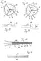
- FIG. 1shows the catch wire structure 1 in a scavenging position in which it is fully advanced out of the sheath 6 and the scavenging portion 4 is in a fully deployed condition.
- the catch wire structure 1By pulling back the puller wire 5 and/or advancing the sheath 6, the catch wire structure 1 can be pulled completely into the sheath 6, with its capture section 4 folding up, ie folding in up to the inner diameter of the sheath 6.
- the catching section 4is approximately in 4 shown, initial shape as it is after slitting and before bending the pipe section 3.
- the techniques for slitting and bending up the piece of pipe 3 in order to achieve the catch wire structure 1are familiar to a person skilled in the art.
- suitable materialsare used for the safety wire structure 1, which can be bent up elastically and fixed elastically in the bent-up state by a treatment process, such as baking or hardening.
- a treatment processsuch as baking or hardening.
- superelastic materialssuch as NiTi alloys are common for this purpose.
- this safety wire instrumentis used in medical applications, such as a stone catcher, for catching stones or other particles in a patient's body tissue from the front in the catching section 4 .
- FIG. 3illustrates such a capture of a particle 8, e.g. a kidney stone, from the front through the capture opening 7 in the proximal direction P parallel to a longitudinal axis 9 of the instrument and thus also of the cup-shaped capture section 4.
- a particle 8e.g. a kidney stone
- Thiscan improve the capture process compared to instruments with front and rear easier with a closed retrieval basket, since the instrument primarily only needs to be moved axially and not in the transverse direction for the retrieval process.
- thismay facilitate the capture of particles in cases where the particles are axially close in front of a vessel wall behind.
- the pipe section 2is provided with a special slit structure during slitting, which comprises open slots 10 opening out at the distal end of the pipe section and intermediate closed axial slits 11 ending at a distance in front of the distal end of the pipe section.
- the closed axial slits 11extend backwards in the proximal direction beyond the distally open slits 10 .
- first, front wire pieces 12 and second, rear wire pieces 13are formed from the relevant distal tube piece section.
- the front wire pieces 12are here in an axial area in which the open slots 10 and the closed slots 11 overlap, with the open and closed slots 10, 11 alternating in the circumferential direction.
- the trailing wire lengths 13are present in the axial region where the closed slots 11 extend proximally beyond the open slots 10 .
- Each rear piece of wire 13branches into two front pieces of wire 12 at the transition area.
- the distance at which the closed slots 11 terminate in front of the distal end of the tube piecedefines a wire piece width b D of a curved wire piece region 12a over which each leading wire piece 12 is connected to an adjacent leading wire piece 12 distally.
- the wire piece width b D of this semicircular curved wire connection area 12a in the example showncan, for example, correspond approximately to the width of the front wire pieces 12 connected thereto, as shown in FIG figure 5 is recognizable.
- a radius of curvature R D of this curved wire connection area 12ais significantly larger than the diameter or the width b D of the wire connection area 12a.
- the aforementioned slit structure of the pipe section 2means that the capture section 4 can be bent open in the desired manner to the aforementioned cup shape with the distal capture opening 7 .
- the rear wire pieces 13form a cup body
- the front wire pieces 12form a distal peripheral edge 14 of the capture cup 4, ie the edge of the distal capture opening 7.
- the length of the front wire pieces 12 and the number thereofdetermines or limits the maximum length of the distal edge of the capture cup 4.
- the distally open slits 10introduced into the tube piece 2 in a suitable length L, which is selected so that the capture section 4 can be bent into the desired cup shape, the length of the cup edge and thus also the circumference of the effective entry cross section of the entry opening 7 being determined by this length L of the open slots 10 and thus of the front wire pieces 12 and by the degree of bending up of the front wire pieces 12 at their wire connection area 12a.
- any number n of closed or distally open slotscan be provided, ie the number n can be any whole number greater than one.
- the cup rim 14lies in axial projection between an inner circle E I and an outer circle E A , with the outer circle E A determining the outer diameter of the capture cup 4 and the inner circle E I representing a capture opening circle, which represents the capture opening 7 bordered by the cup rim 14 in a good approximation .
- the circumferential length U of this effective capture opening circle E Iis only slightly smaller than the actual circumferential length of the cup edge 4, which is formed by the product 2nL of the number 2n of the wire pieces 12 , 13 multiplied by the length L of the open axial slots 10 plus the length contribution by the wire bonding portions 12a.
- the capture opening 7can be provided with a desired large capture cross section. If the front wire pieces 12 are bent up by an angle of less than 180° in their wire connection area 12a, the cup rim 4 becomes more wavy with a smaller bent-up angle, which means that the cup rim length increases slightly compared to the circumferential length U of the effective capture opening circle E I .
- the circumferential length U of the catch opening circle E Iis kept at a value of at least 70% of the product 2nL of the number 2n of front wire pieces 12 and their length L. This leads to favorable cup shapes of the catch section 4 with a comparatively large catch opening 7 and only moderately wavy course of the cup edge 14.
- any desired configurationscan be realized for the capture cup 4 by using a corresponding bending mold introduced into the slotted distal tubular piece area for bending open.
- the Figures 8 to 10show three representative examples.
- the catch wire structurehas a catch section 4a which widens degressively from the base section 3 in the distal direction, ie less than linearly. At a distance in front of the distal capture opening 7 , it then assumes a maximum diameter DE or cross section, from which it narrows to a somewhat smaller diameter D 0 or cross section of the capture opening 7 .
- the distal narrowing of the capture cup 4acan aid in securely holding a captured object.
- a capture cup 4bextends distally from the base portion 3 with a linear increase in its flare diameter.
- a capture goblet 4cextends from
- FIG. 11 to 16illustrate advantageous embodiments of the safety wire instrument according to the invention, which are particularly suitable for MR applications and are provided with an MR marker material in a manner known per se for this purpose.
- Fig.11 1shows an example in which the safety wire structure 1 is coated with an MR marker material 15 over its entire surface, as indicated by a puncturing of the coated outer surfaces of the safety wire structure 1.
- FIG 12shows a variant of the embodiment of FIG 11 , are provided with an MR marker material 16 in the part-area and punctiform areas of the catch wire structure 1 .
- the detail view of 13shows a partial surface coating of the rear wire pieces 13 by a row of spaced, elongate MR marker strips 16a arranged one behind the other.
- corresponding MR marker stripscan be provided on the front pieces of wire 12 .
- 14shows a detailed view of a punctiform MR marker spot 16b, which is attached in each case in the area of the branching point at which the rear piece of wire 13 branches into the two front pieces of wire 12.
- FIG. 15illustrates an embodiment variant in which the puller wire 5 is formed by a wire core 5a and a core sheath 5b surrounding it, rings 16c made of an MR marker material being applied to the wire core 5a at an axial distance from one another and embedded by the sheath 5b.
- 16shows a variant in which the tubular covering 6, in which the puller wire 5 is guided in an axially movable manner, is provided with an axially extending, line-shaped MR marker material 16d.
- the capture cuphas a more strongly branched structure in the area of its cup body.
- further closed slitsare introduced into the tube piece, these further closed slits overlapping axially with the closed slits already mentioned and extending beyond them in the proximal direction.
- the further closed axial slits in the overlapping areacan preferably in turn alternate with the other closed slits in the circumferential direction. This then results in a lattice-like, branched structure of the cup body.
- the inventionprovides a safety wire instrument that can be used in particular as a medical safety wire instrument, e.g. in MR applications, and allows foreign bodies, particles, etc. to be safely captured from the front.
- the safety wire structureis produced in one piece from a piece of tubing, which is advantageous in terms of production technology.
- wire connectionssuch as welds, to be specially made. Accordingly, there are no problems with breakage or other failure of corresponding welds or glues or other joints.
Landscapes
- Health & Medical Sciences (AREA)
- Life Sciences & Earth Sciences (AREA)
- Surgery (AREA)
- Heart & Thoracic Surgery (AREA)
- Public Health (AREA)
- Veterinary Medicine (AREA)
- Engineering & Computer Science (AREA)
- Biomedical Technology (AREA)
- General Health & Medical Sciences (AREA)
- Animal Behavior & Ethology (AREA)
- Molecular Biology (AREA)
- Medical Informatics (AREA)
- Nuclear Medicine, Radiotherapy & Molecular Imaging (AREA)
- Vascular Medicine (AREA)
- Orthopedic Medicine & Surgery (AREA)
- Surgical Instruments (AREA)
- Cardiology (AREA)
- Oral & Maxillofacial Surgery (AREA)
- Transplantation (AREA)
Description
Translated fromGermanDie Erfindung bezieht sich auf ein Fangdrahtinstrument nach dem Oberbegriff des Anspruchs 1.The invention relates to a safety wire instrument according to the preamble of
Derartige Fangdrahtinstrumente werden insbesondere als medizinische Fangdrahtinstrumente verwendet, um Fremdkörper, Blutklumpen, Steine, oder andere Ablagerungen aus menschlichen oder tierischen Geweben entfernen bzw. abfangen zu können, vorzugsweise unter Benutzung eines entsprechenden Katheterinstruments.Such safety wire instruments are used in particular as medical safety wire instruments in order to be able to remove or intercept foreign bodies, blood clots, stones or other deposits from human or animal tissue, preferably using a corresponding catheter instrument.
Bei einem bekannten Typ solcher Instrumente hat der aufgefaltete Einfangabschnitt eine Korbform, d.h. er bildet einen Fangkorb, der zusammengefaltet in der Umhüllung aufgenommen und aus dieser nach vorn herausbewegt werden kann, wodurch er sich zu seiner Korbform auffaltet. Steine und dergleichen können dann quer zur Längsachse des Drahtkorbs im Bereich von dessen maximalem Durchmesser und damit maximaler Öffnungsweite in den Drahtkorb eingefangen werden. Denn in diesem Bereich haben benachbarte Drahtabschnitte der korbbildenden Fangdrahtstruktur ihren maximalen Abstand, wodurch dort korbumfangsseitig entsprechende Einfangöffnungen gebildet sind. Durch wenigstens teilweises Zurückziehen des Drahtkorbs in die Umhüllung wird dieser eingefaltet, bis er das eingefangene Objekt eng umschließt und dieses dadurch festhält. Anschließend kann der Drahtkorb samt Umhüllung und eingefangenem Objekt aus dem betreffenden Gewebekanal herausbewegt werden. Steinfangkorb- bzw. Ballonkatheterinstrumente dieser Art sind z.B. in der Patentschrift
Ein weiterer bekannter Typ solcher Fangdrahtinstrumente sind sogenannte Fangschlingeninstrumente, bei denen die Fangdrahtstruktur aus einer oder mehreren zusammenwirkenden Drahtschlingen gebildet ist, die frontseitig lose oder gefasst sein können, siehe z.B. die Offenlegungsschrift
In den Offenlegungsschriften
Dokumente
Der Erfindung liegt als technisches Problem die Bereitstellung eines Fangdrahtinstruments der eingangs genannten Art zugrunde, das eine gute Fangfunktionalität und hohe Funktionszuverlässigkeit bietet und sich mit vergleichsweise geringem Aufwand fertigen lässt.The invention is based on the technical problem of providing a catch wire instrument of the type mentioned at the outset, which offers good catch functionality and high functional reliability and can be manufactured with comparatively little effort.
Die Erfindung löst dieses Problem durch die Bereitstellung eines Fangdrahtinstrumentes mit den Merkmalen des Anspruchs 1. Weitere bevorzugte Ausführungsformen werden in den Unteransprüchen dargelegt. Bei diesem erfindungsgemäßen Fangdrahtinstrument weist der Einfangabschnitt im aufgefalteten Zustand eine Kelchform mit distaler Einfangöffnung auf. Unter Einfangöffnung ist dabei vorliegend der Bereich maximaler Öffnungsweite der Fangdrahtstruktur zu verstehen, der dazu bestimmt und eingerichtet ist, durch ihn hindurch einzufangende Objekte in das Innere der Fangdrahtstruktur hineingelangen zu lassen. Zu diesem Zweck sind in einen distalen Endbereich des zur Herstellung der Fangdrahtstruktur verwendeten Rohrstücks vom Rohrstückende her offene axiale Schlitze geeigneter Länge sowie zwischenliegende, mit Abstand vor dem distalen Rohrstückende endende, geschlossene axiale Schlitze eingebracht, wobei die geschlossenen axialen Schlitze länger als die offenen axialen Schlitze sind und sich daher in proximaler Richtung über die offenen axialen Schlitze hinaus erstrecken. Die verbleibenden Rohrstückbereiche zwischen den offenen und geschlossenen axialen Schlitzen bilden Drahtstücke, die durch das Aufbiegen des Rohrstücks Umfangsabschnitte der Einfangöffnung bilden. Der Einfangabschnitt kann von seinem aufgefalteten, kelchförmigen Zustand bei Bedarf wieder vollständig in eine dem Rohrstück entsprechende Form eingefaltet bzw. zusammengefaltet werden, wenn die Fangdrahtstruktur vollständig in die Umhüllung zurückbewegt wird.The invention solves this problem by providing a safety wire instrument with the features of
Mit dem erfindungsgemäßen Fangdrahtinstrument können Steine und andere Partikel in Körpergeweben in einer vorteilhaften Weise von vorn eingefangen werden, d.h. sie gelangen von vorn durch die distale Einfangöffnung in axialer Richtung in den kelchförmig aufgefalteten Einfangabschnitt. Dazu kann die Fangdrahtstruktur entsprechend axial vorbewegt werden. Auf diese Weise lassen sich auch Partikel, die sich in distaler Richtung nahe einer Gewebewand befinden, problemlos einfangen. Das erfindungsgemäße Instrument kann auch dazu verwendet werden, nach Art eines Filters oder Stents Fremdkörper aus Blutbahnen und anderen Körpergefäßen zu entfernen bzw. abzufangen.With the safety wire instrument according to the invention, stones and other particles in body tissues can be trapped in an advantageous manner from the front, ie they come from forward through the distal catching opening in the axial direction into the cup-shaped catching section. For this purpose, the safety wire structure can be advanced axially accordingly. In this way, particles that are close to a tissue wall in the distal direction can also be captured without any problems. The instrument according to the invention can also be used to remove or intercept foreign bodies from blood vessels and other body vessels in the manner of a filter or stent.
Das erfindungsgemäße Fangdrahtinstrument lässt sich mit relativ geringem Aufwand herstellen, indem seine Fangdrahtstruktur einteilig aus einem Rohrstück gebildet wird, das zu diesem Zweck in an sich bekannter Weise geschlitzt und aufgebogen wird. Schweißstellen zum Verbinden von Drahtstücken können entfallen. Indem die am distalen Rohrstückende offen ausmündenden Schlitze eine geeignete Länge aufweisen, können die Drahtstücke, die aus dem Rohrstück durch die offenen und geschlossenen axialen Schlitze in deren axialem Überlappungsbereich gebildet sind, den Umfang der Einfangöffnung bilden, d.h. den distalen Rand der Kelchform des aufgefalteten Einfangabschnitts. Durch die Länge der offenen axialen Schlitze lässt sich somit die Umfangslänge und damit auch der Einfangquerschnitt bzw. die Öffnungsweite des Einfangkelches vorgeben. Mit größerer Länge der offenen axialen Schlitze kann die Umfangslänge und damit der Einfangquerschnitt des Einfangkelches erhöht werden. Da sich die geschlossenen axialen Schlitze proximal über die offenen axialen Schlitze hinaus erstrecken, teilen sie das Rohrstück in dem proximalen Bereich hinter den offenen axialen Schlitzen in hintere Drahtstücke, die im aufgefalteten Zustand einen Kelchkörper für den Einfangkelch bilden, wobei dieser Kelchkörper an seinem distalen Ende wie erwähnt mit den durch die vorderen Drahtstücke gebildeten Kelchrand abschließt. Dabei verzweigt sich jedes hintere Drahtstück in zwei vordere Drahtstücke.The safety wire instrument according to the invention can be produced with relatively little effort in that its safety wire structure is formed in one piece from a piece of tubing which is slotted and bent open for this purpose in a manner known per se. Welds for connecting pieces of wire can be omitted. By having the slits opening open at the distal end of the tubing of a suitable length, the pieces of wire formed from the tubing through the open and closed axial slits in their axial overlap region can form the perimeter of the catching opening, i.e. the distal edge of the cup shape of the unfolded catching section . The circumferential length and thus also the capture cross-section or the opening width of the capture cup can thus be specified by the length of the open axial slots. With a greater length of the open axial slits, the circumferential length and thus the capture cross-section of the capture cup can be increased. As the closed axial slits extend proximally beyond the open axial slits, they divide the tubing in the proximal region behind the open axial slits into rear lengths of wire which, when unfolded, form a calyx body for the capture calyx, this calyx body at its distal end as mentioned, ends with the edge of the cup formed by the front pieces of wire. Each rear piece of wire branches into two front pieces of wire.
In einer Weiterbildung der Erfindung hängen je zwei benachbarte vordere Drahtstücke, die aus dem Rohrstück durch die offenen und geschlossenen axialen Schlitze gebildet sind, über einen Krümmungsbereich zusammen, dessen Radius RD mindestens so groß ist wie das Zweieinhalbfache einer Breite bD der Drahtstücke im Krümmungsbereich, d.h. RD ≥ 2,5×bD. Es zeigt sich, dass sich die Drahtstücke durch diese Dimensionierungsmaßnahme sehr vorteilhaft unter Bildung des Kelchrandes aufbiegen lassen, ohne dass Bruchgefahr besteht, wobei spitz zulaufende Kelchrandbereiche vermieden werden, die im Gebrauch zu Gewebeverletzungsrisiken führen könnten.In a further development of the invention, two adjacent front wire pieces, which are formed from the pipe piece by the open and closed axial slots, are connected via a curved area whose radius RD is at least as large as two and a half times a width bD of the wire pieces in the curved area , i.e. RD ≥ 2.5×bD . It has been shown that this dimensioning measure allows the wire pieces to be bent up very advantageously to form the cup edge without the risk of breakage, with the cup edge areas tapering to a point being avoided, which could lead to the risk of tissue damage during use.
In einer Weiterbildung der Erfindung beträgt eine Umfangslänge U der Einfangöffnung 70% oder mehr des Produkts aus der Anzahl 2n der durch die offenen und geschlossenen axialen Schlitze aus dem Rohrstück gebildeten Drahtstücke multipliziert mit der Länge L der offenen axialen Schlitze, d.h. U ≥ 0,7×2nL. Diese Dimensionierungsmaßnahme ermöglicht die Bereitstellung eines vergleichsweise großen Einfangquerschnitts mit einem Kelchrand, der in axialer Richtung allenfalls stumpfwinklige und keine spitzwinkligen V-förmigen Abschnitte aufweist.In a development of the invention, a circumferential length U of the catching opening is 70% or more of the product of the number 2n of wire pieces formed by the open and closed axial slits in the tube piece multiplied by the length L of the open ones axial slots, ie U ≥ 0.7×2nL. This dimensioning measure makes it possible to provide a comparatively large capture cross-section with a cup edge which, in the axial direction, has at most obtuse-angled and no acute-angled V-shaped sections.
Je nach dem verwendeten Aufbiegevorgang lassen sich in Weiterbildung der Offenbarung unterschiedliche Kelchformen für den Einfangabschnitt im aufgefalteten Zustand mit Bereichen erzielen, in denen der Kelchdurchmesser in distaler Richtung linear, progressiv oder degressiv zunimmt.Depending on the bending process used, in a further development of the disclosure, different cup shapes can be achieved for the capture section in the unfolded state with areas in which the cup diameter increases linearly, progressively or degressively in the distal direction.
Entsprechend der Erfindung ist ein maximaler Querschnitt der Kelchform des Einfangabschnitts im aufgefalteten Zustand größer als ein Querschnitt der Einfangöffnung. Dies kann in bestimmten Anwendungsfällen das Festhalten eines eingefangenen Partikels im eingefalteten Einfangkelch erleichtern.According to the invention, a maximum cross section of the cup shape of the catching section in the unfolded state is larger than a cross section of the catching opening. In certain applications, this can make it easier to hold a captured particle in the folded-in capture cup.
In einer Weiterbildung der Erfindung umfasst der Einfangabschnitt weitere, zweite geschlossene axiale Schlitze im Rohrstück, die sich nach vorn mit ihrem distalen Ende auf Höhe zwischen einem distalen und einem proximalen Ende der ersten geschlossenen axialen Schlitze und nach hinten mit ihrem proximalen Ende hinter dem proximalen Ende der ersten geschlossenen axialen Schlitze erstrecken. Dies ermöglicht eine drahtverzweigende Konfiguration des in diesem Fall von den ersten und zweiten geschlossenen axialen Schlitzen gebildeten Kelchkörpers.In a further development of the invention, the capture section comprises further, second closed axial slots in the tube piece, which extend forwards with their distal end level between a distal and a proximal end of the first closed axial slots and backwards with their proximal end behind the proximal end of the first closed axial slots. This enables a wire-branching configuration of the cup body formed in this case by the first and second closed axial slots.
In einer Weiterbildung der Erfindung ist die Fangdrahtstruktur und/oder die Umhüllung und/oder der in der Umhüllung axial beweglich geführter Zugdraht für die Fangdrahtstruktur ganzflächig oder teilflächig oder punktuell mit einem Magnetresonanz(MR)-Markermaterial versehen. Dies ermöglicht eine vorteilhafte Verwendung des Fangdrahtinstrumentes in entsprechenden MR-Anwendungen, indem seine Fangdrahtstruktur MR-sichtbar ist.In a further development of the invention, the safety wire structure and/or the cover and/or the pull wire for the safety wire structure, which is guided in an axially movable manner in the cover, is provided with a magnetic resonance (MR) marker material over the whole area or part of the area or at certain points. This enables advantageous use of the safety wire instrument in corresponding MR applications, in that its safety wire structure is MR-visible.
Vorteilhafte Ausführungsformen der Erfindung sind in den Zeichnungen dargestellt und werden nachfolgend beschrieben. Hierbei zeigen:
- Fig. 1
- eine schematische Längsschnittansicht eines Fangdrahtinstruments mit kelchförmigem Einfangabschnitt,
- Fig. 2
- eine perspektivische Ansicht eines Einfangabschnitts einer Fangdrahtstruktur des Instruments von
Fig. 1 , - Fig. 3
- eine schematische Seitenansicht des Einfangabschnitts von
Fig. 2 zur Erläuterung eines Partikeleinfangvorgangs, - Fig. 4
- eine Abwicklungsdarstellung eines geschlitzten Rohrstücks für die Fangdrahtstruktur des Instruments von
Fig. 1 , - Fig. 5
- eine Detailansicht eines distalen Drahtstück-Verbindungsbereichs des geschlitzten Rohrstücks von
Fig. 4 , - Fig. 6
- die Ansicht von
Fig. 5 nach Aufbiegen des geschlitzten Rohrstücks zur Bildung des kelchförmigen Einfangabschnitts, - Fig. 7
- eine Draufsicht von vorn auf den kelchförmigen Einfangabschnitt,
- Fig. 8
- eine schematische Seitenansicht einer Fangdrahtstruktur mit in distaler Richtung degressiv zunehmendem Durchmesser des Einfangkelchs,
- Fig. 9
- eine Ansicht entsprechend
Fig. 8 für eine Fangdrahtstruktur mit in distaler Richtung linear zunehmendem Einfangkelchdurchmesser, - Fig. 10
- eine Ansicht entsprechend
Fig. 8 für eine Fangdrahtstruktur mit distaler Richtung progressiv zunehmendem Einfangkelchdurchmesser, - Fig. 11
- eine Draufsicht entsprechend
Fig. 7 auf einen anderen Einfangkelch mit drei statt vier hinteren Kelchkörper-Drahtstücken und mit ganzflächiger MR-Markerbeschichtung, - Fig. 12
- eine Ansicht entsprechend
Fig. 11 für eine Variante mit teilflächig und punktuell aufgebrachtem MR-Markermaterial, - Fig. 13
- eine Detailansicht von
Fig. 12 eines Bereichs mit teilflächigem MR-Markermaterial, - Fig. 14
- eine Detailansicht von
Fig. 12 mit punktuell aufgebrachtem MR-Markermaterial, - Fig. 15
- eine Detailschnittansicht des Instruments von
Fig. 1 mit MR-Markermaterial in einem Schaftbereich und - Fig. 16
- eine Seitenansicht einer Umhüllung mit MR-Markermaterial, wie sie für das Instrument von
Fig. 1 verwendbar ist.
- 1
- a schematic longitudinal sectional view of a safety wire instrument with a cup-shaped safety section,
- 2
- 14 is a perspective view of a capture portion of a capture wire structure of the instrument of FIG
1 , - 3
- a schematic side view of the capture portion of FIG
2 to explain a particle capture process, - 4
- Fig. 12 is a development view of a slotted length of tubing for the instrument's safety wire structure of Fig
1 , - figure 5
- FIG. 12 is a detailed view of a distal wire piece connection area of the slotted tubing of FIG
4 , - 6
- the view of
figure 5 after bending open the slotted piece of pipe to form the cup-shaped capture section, - 7
- a front plan view of the cup-shaped capture portion,
- 8
- a schematic side view of a catch wire structure with the diameter of the catch cup increasing degressively in the distal direction,
- 9
- a view accordingly
8 for a catch wire structure with a linearly increasing cup diameter in the distal direction, - 10
- a view accordingly
8 for a catch wire structure with a progressively increasing cup diameter in the distal direction, - 11
- a top view accordingly
7 to another capture goblet with three instead of four rear goblet body wire pieces and with a full-surface MR marker coating, - 12
- a view accordingly
11 for a variant with partial and selectively applied MR marker material, - 13
- a detailed view of
12 an area with partial MR marker material, - 14
- a detailed view of
12 with selectively applied MR marker material, - 15
- a detailed sectional view of the instrument from
1 with MR marker material in a shaft area and - 16
- a side view of an envelope with MR marker material, as for the instrument of
1 is usable.
Das in den
Die Fangdrahtstruktur 1 ist an ihrem proximalen Endbereich mit einem distalen Endbereich eines als Zugdraht bezeichneten Betätigungselements 5 gekoppelt, das in einer Umhüllung 6 axial beweglich geführt ist. Die Kopplung ist vorzugsweise dergestalt realisiert, dass der proximale Endbereich der Fangdrahtstruktur 1 bleibend und axial bewegungsstarr mit dem distalen Endbereich des Betätigungselements 5 verbunden ist, z.B. durch eine Klebe- oder Schweißverbindung. Dadurch kann die Fangdrahtstruktur 1 mittels entsprechender axialer Betätigungsbewegung des Betätigungselements 5 sowohl axial nach vorn als auch axial nach hinten bewegt werden. Zugdraht 5 und Umhüllung 6 sind vorzugsweise aus einem elastisch biegefähigen Material gefertigt. In
Wie insbesondere aus den
Wie insbesondere aus den
Der Abstand, mit dem die geschlossenen Schlitze 11 vor dem distalen Rohrstückende enden, definiert eine Drahtstückbreite bD eines gekrümmten Drahtstückbereichs 12a, über den jedes vordere Drahtstück 12 mit einem benachbarten vorderen Drahtstück 12 distal zusammenhängt. Die Drahtstückbreite bD dieses im gezeigten Beispiel halbkreisförmig gekrümmten Drahtverbindungsbereichs 12a kann z.B. in etwa der Breite der damit verbundenen vorderen Drahtstücke 12 entsprechen, wie dies aus
Die erwähnte Schlitzstruktur des Rohrstücks 2 führt dazu, dass sich der Einfangabschnitt 4 in gewünschter Weise zu der erwähnten Kelchform mit der distalen Einfangöffnung 7 aufbiegen lässt. Dabei bilden, wie aus
Im gezeigten Beispiel von
Die erwähnten Dimensionierungsverhältnisse lassen sich anhand der Draufsicht auf den Einfangkelch 4 bzw. dessen Einfangöffnung 7 näher erläutern, wie sie in
Wenn die vorderen Drahtstücke 12 an ihren Drahtverbindungsbereichen 12a um ca. 180° aufgebogen sind, wie im Beispiel von
Somit lässt sich durch Wahl einer genügend großen Länge L der distal offenen Schlitze 10 die Einfangöffnung 7 mit einem gewünscht großen Einfangquerschnitt bereitstellen. Wenn die vorderen Drahtstücke 12 in ihrem Drahtverbindungsbereich 12a um einen kleineren Winkel als 180° aufgebogen werden, ergibt sich mit kleinerem Aufbiegewinkel ein welligerer Verlauf des Kelchrandes 4, wodurch die Kelchrandlänge verglichen mit der Umfangslänge U des effektiven Einfangöffnungskreises EI etwas zunimmt. In vorteilhaften Ausführungsformen wird die Umfangslänge U des Einfangöffnungskreises EI auf einem Wert von mindestens 70% des Produkts 2nL aus der Anzahl 2n der vorderen Drahtstücke 12 und deren Länge L gehalten. Dies führt zu günstigen Kelchformen des Einfangabschnitts 4 mit vergleichsweise großer Einfangöffnung 7 und nur mäßig welligem Verlauf des Kelchrandes 14.Thus, by choosing a sufficiently large length L of the distally
Für den Einfangkelch 4 lassen sich durch Verwendung einer entsprechenden, zum Aufbiegen in den geschlitzten distalen Rohrstückbereich eingebrachten Biegeform beliebige gewünschte Gestaltungen realisieren. Die
erfindungsgemäßen Ausführungsvariante von
embodiment of the invention
Bei einer in
Basisabschnitt 3 in distaler Richtung mit einer progressiven, d.h. stärker als linearen, Zunahme seines Durchmessers. Es sei erwähnt, dass auch die Kelchvarianten der
Die
Im Beispiel von
In nicht gezeigten Ausführungsformen der Erfindung weist der Einfangkelch im Bereich seines Kelchkörpers eine stärker verzweigte Struktur auf. Dazu sind dann außer den distal offenen Schlitzen und den mit diesen in axialer Richtung überlappenden, geschlossenen Schlitzen weitere geschlossene Schlitze in das Rohrstück eingebracht, wobei diese weiteren geschlossenen Schlitze axial mit den bereits genannten geschlossenen Schlitzen überlappen und sich in proximaler Richtung über diese hinaus erstrecken. Dabei können sich vorzugsweise wiederum die weiteren geschlossenen axialen Schlitze im Überlappungsbereich in Umfangsrichtung mit den anderen geschlossenen Schlitzen abwechseln. Dies resultiert dann in einer gitterartig verzweigten Struktur des Kelchkörpers.In non-illustrated embodiments of the invention, the capture cup has a more strongly branched structure in the area of its cup body. For this purpose, in addition to the distally open slits and the closed slits overlapping with them in the axial direction, further closed slits are introduced into the tube piece, these further closed slits overlapping axially with the closed slits already mentioned and extending beyond them in the proximal direction. The further closed axial slits in the overlapping area can preferably in turn alternate with the other closed slits in the circumferential direction. This then results in a lattice-like, branched structure of the cup body.
Wie die obige Beschreibung vorteilhafter Ausführungsbeispiele deutlich macht, stellt die Erfindung ein Fangdrahtinstrument zur Verfügung, das sich insbesondere als medizinisches Fangdrahtinstrument z.B. auch in MR-Anwendungen verwenden lässt und ein sicheres Einfangen von Fremdkörpern, Partikeln etc. von der Frontseite her erlaubt. Dabei wird die Fangdrahtstruktur in fertigungstechnisch vorteilhafter Weise einstückig aus einem Rohrstück hergestellt. Es brauchen dazu keine Drahtverbindungen, wie Schweißstellen, eigens hergestellt werden. Dementsprechend gibt es keine Probleme mit einem Brechen oder einem sonstigen Ausfall entsprechender Schweißstellen oder Klebestellen oder anderweitiger Verbindungsstellen.As the above description of advantageous exemplary embodiments makes clear, the invention provides a safety wire instrument that can be used in particular as a medical safety wire instrument, e.g. in MR applications, and allows foreign bodies, particles, etc. to be safely captured from the front. In this case, the safety wire structure is produced in one piece from a piece of tubing, which is advantageous in terms of production technology. There is no need for wire connections, such as welds, to be specially made. Accordingly, there are no problems with breakage or other failure of corresponding welds or glues or other joints.
Claims (6)
- Snare instrument, in particular a medical snare instrument, with- a snare structure (1) which is formed in one piece from a tube section (2), by the latter being slit and bent open, and which has a proximal base portion (3) and, extending axially forward from the latter, a distal snaring portion (4), and which is movable between a snaring position, in which it is moved forward out of an enclosure (6) with the snaring portion folded open, and a securing position, in which it is moved back at least partially into the enclosure with the snaring portion folded in and providing a securing action, and- a pulling-wire actuation element (5) which is guided axially movably in the enclosure, wherein the proximal end region of the snare structure is coupled to a distal end region of the pulling-wire actuation element,
characterized in that- the snaring portion (4), in the folded-open state, has a cup shape with a distal snare opening (7), and, for this purpose, a distal end region of the tube section (2) is provided with open axial slits (10) of suitable length introduced from the direction of the distal end of the tube section, and, lying between these, with associated closed axial slits (11) which terminate at a distance in front of the distal end of the tube section and are of greater length than the open axial slits, wherein, by means of the open and closed axial slits, wire sections (12) are formed from the tube section and, when the tube section is bent open, the wire sections (12) form circumferential portions of the snare opening,- furthercharacterized in that a maximum diameter (DE) of the cup shape of the snaring portion in the folded-open state is greater than a diameter (Do) of the snare opening. - Snare instrument according to Claim 1, furthercharacterized in that two adjacent wire sections, formed from the tube section by the open and closed axial slits, are in each case joined together via a region of curvature (12a), of which the radius (RD) is at least as great as two and a half times a width (bD) of the wire sections in the region of curvature.
- Snare instrument according to Claim 1 or 2, furthercharacterized in that a circumferential length of an effective snare opening circle is 70% or more of the product (2nL) of a number (2n) of the wire sections (12) formed from the tube section by the open and closed axial slits, multiplied by the length (L) of the open axial slits.
- Snare instrument according to one of Claims 1 to 3, furthercharacterized in that the cup shape of the snaring portion in the folded-open state comprises one or more regions in which the cup diameter increases linearly, progressively or degressively in the distal direction.
- Snare instrument according to one of Claims 1 to 4, furthercharacterized in that the snaring portion comprises second closed axial slits in the tube section, which slits extend forward as far as a distal end at the level between a distal and a proximal end of the first closed axial slits and rearward as far as a proximal end behind the proximal end of the first closed axial slits.
- Snare instrument according to one of Claims 1 to 5, furthercharacterized in that the snare structure and/or the enclosure (6) and/or the pulling-wire actuation element (5) guided axially movably in the enclosure for the snare structure is provided across the whole surface or a partial surface, or at points, with a magnetic resonance (MR) marker material (16a, 16b, 16c, 16d).
Applications Claiming Priority (2)
| Application Number | Priority Date | Filing Date | Title |
|---|---|---|---|
| DE102014205366.8ADE102014205366B4 (en) | 2014-03-21 | 2014-03-21 | Catch wire instrument with catch wire structure made of tubular piece |
| PCT/EP2015/054894WO2015139998A1 (en) | 2014-03-21 | 2015-03-10 | Snare instrument with snare structure composed of a tubular piece |
Publications (3)
| Publication Number | Publication Date |
|---|---|
| EP3119292A1 EP3119292A1 (en) | 2017-01-25 |
| EP3119292B1true EP3119292B1 (en) | 2023-08-16 |
| EP3119292C0 EP3119292C0 (en) | 2023-08-16 |
Family
ID=52649017
Family Applications (1)
| Application Number | Title | Priority Date | Filing Date |
|---|---|---|---|
| EP15709151.3AActiveEP3119292B1 (en) | 2014-03-21 | 2015-03-10 | Snare instrument with snare structure composed of a tubular piece |
Country Status (6)
| Country | Link |
|---|---|
| US (1) | US10478203B2 (en) |
| EP (1) | EP3119292B1 (en) |
| JP (1) | JP6549609B2 (en) |
| CN (1) | CN106456199B (en) |
| DE (1) | DE102014205366B4 (en) |
| WO (1) | WO2015139998A1 (en) |
Families Citing this family (7)
| Publication number | Priority date | Publication date | Assignee | Title |
|---|---|---|---|---|
| DE102014208168A1 (en) | 2014-04-30 | 2015-11-19 | Epflex Feinwerktechnik Gmbh | Fangkelinstrument with distal Fangkelchstruktur |
| DE102017205725B4 (en) | 2017-04-04 | 2018-12-06 | Epflex Feinwerktechnik Gmbh | Medical claw instrument |
| EP4368156A3 (en) | 2017-11-09 | 2024-11-06 | ConvaTec Technologies Inc. | Ostomy monitoring system and method |
| USD893514S1 (en) | 2018-11-08 | 2020-08-18 | 11 Health And Technologies Limited | Display screen or portion thereof with graphical user interface |
| US12357494B2 (en) | 2020-10-15 | 2025-07-15 | Convatec Technologies Inc. | Ostomy systems and methods |
| KR102528715B1 (en)* | 2020-10-28 | 2023-05-04 | 사회복지법인 삼성생명공익재단 | Medical snare apparatus |
| DE102023109898A1 (en) | 2023-04-19 | 2024-10-24 | EPflex Feinwerktechnik GmbH. | Medical guidewire with twisted core wire |
Citations (3)
| Publication number | Priority date | Publication date | Assignee | Title |
|---|---|---|---|---|
| WO2003075793A1 (en)* | 2002-03-06 | 2003-09-18 | Boston Scientific Limited | Medical retrieval device |
| US20120116440A1 (en)* | 2004-09-10 | 2012-05-10 | Penumbra, Inc. | System and method for treating ischemic stroke |
| US20130289578A1 (en)* | 2012-04-13 | 2013-10-31 | Yawa-Med, Inc. | Blood clot extraction device |
Family Cites Families (21)
| Publication number | Priority date | Publication date | Assignee | Title |
|---|---|---|---|---|
| DE19722429A1 (en) | 1997-05-28 | 1998-12-03 | Optimed Medizinische Instr Gmb | Capturing or reducing gall stones and kidney stones in hollow organs |
| WO2002078632A2 (en) | 2001-04-02 | 2002-10-10 | Acmi Corporation | Retrieval basket for a surgical device and system and method for manufacturing same |
| US7101379B2 (en) | 2001-04-02 | 2006-09-05 | Acmi Corporation | Retrieval basket for a surgical device and system and method for manufacturing same |
| US20030181942A1 (en)* | 2002-01-25 | 2003-09-25 | Sutton Gregg S. | Atrial appendage blood filtration systems |
| US20030187495A1 (en) | 2002-04-01 | 2003-10-02 | Cully Edward H. | Endoluminal devices, embolic filters, methods of manufacture and use |
| WO2004100772A2 (en)* | 2003-05-12 | 2004-11-25 | University Of Florida | Devices and methods for disruption and removal of luninal occlusions |
| US7744604B2 (en) | 2003-11-13 | 2010-06-29 | Lawrence Livermore National Security, Llc | Shape memory polymer medical device |
| US7338512B2 (en)* | 2004-01-22 | 2008-03-04 | Rex Medical, L.P. | Vein filter |
| US7704266B2 (en) | 2004-01-22 | 2010-04-27 | Rex Medical, L.P. | Vein filter |
| US7166846B2 (en)* | 2004-06-30 | 2007-01-23 | Siemens Medical Solutions Usa, Inc. | Multi-pinhole collimation for nuclear medical imaging |
| DE102004055375B4 (en) | 2004-11-08 | 2007-12-06 | Epflex Feinwerktechnik Gmbh | Multi-wire unit and manufacturing method thereof |
| ATE480206T1 (en)* | 2006-03-03 | 2010-09-15 | Prescient Medical Inc | ENDOLUMINAL PROSTHESIS FOR THE TREATMENT OF SENSITIVE PLAQUE |
| US10123803B2 (en)* | 2007-10-17 | 2018-11-13 | Covidien Lp | Methods of managing neurovascular obstructions |
| EP2052688B1 (en)* | 2007-10-25 | 2012-06-06 | pfm medical ag | Snare mechanism for surgical retrieval |
| US20090192485A1 (en) | 2008-01-28 | 2009-07-30 | Heuser Richard R | Snare device |
| CN102186427B (en)* | 2008-09-22 | 2013-12-18 | 浩特斯博尔技术公司 | flow recovery system |
| US20120116496A1 (en)* | 2010-11-05 | 2012-05-10 | Chuter Timothy A | Stent structures for use with valve replacements |
| US8469970B2 (en)* | 2011-07-11 | 2013-06-25 | Great Aspirations Ltd. | Apparatus for entrapping and extracting objects from body cavities |
| US9861370B2 (en) | 2011-11-09 | 2018-01-09 | Boston Scientific Scimed Inc. | Occlusion device |
| EP2854700B1 (en) | 2012-05-31 | 2021-07-07 | Javelin Medical Ltd. | Devices for embolic protection |
| US9445828B2 (en)* | 2012-07-05 | 2016-09-20 | Cognition Medical Corp. | Methods, devices, and systems for postconditioning with clot removal |
- 2014
- 2014-03-21DEDE102014205366.8Apatent/DE102014205366B4/enactiveActive
- 2015
- 2015-03-10CNCN201580025972.9Apatent/CN106456199B/ennot_activeExpired - Fee Related
- 2015-03-10EPEP15709151.3Apatent/EP3119292B1/enactiveActive
- 2015-03-10JPJP2016559248Apatent/JP6549609B2/enactiveActive
- 2015-03-10USUS15/127,501patent/US10478203B2/enactiveActive
- 2015-03-10WOPCT/EP2015/054894patent/WO2015139998A1/enactiveApplication Filing
Patent Citations (3)
| Publication number | Priority date | Publication date | Assignee | Title |
|---|---|---|---|---|
| WO2003075793A1 (en)* | 2002-03-06 | 2003-09-18 | Boston Scientific Limited | Medical retrieval device |
| US20120116440A1 (en)* | 2004-09-10 | 2012-05-10 | Penumbra, Inc. | System and method for treating ischemic stroke |
| US20130289578A1 (en)* | 2012-04-13 | 2013-10-31 | Yawa-Med, Inc. | Blood clot extraction device |
Also Published As
| Publication number | Publication date |
|---|---|
| EP3119292A1 (en) | 2017-01-25 |
| JP2017512574A (en) | 2017-05-25 |
| CN106456199A (en) | 2017-02-22 |
| US20170143357A1 (en) | 2017-05-25 |
| DE102014205366A1 (en) | 2015-09-24 |
| DE102014205366B4 (en) | 2019-03-28 |
| JP6549609B2 (en) | 2019-07-24 |
| CN106456199B (en) | 2019-01-01 |
| EP3119292C0 (en) | 2023-08-16 |
| WO2015139998A1 (en) | 2015-09-24 |
| US10478203B2 (en) | 2019-11-19 |
Similar Documents
| Publication | Publication Date | Title |
|---|---|---|
| EP3119292B1 (en) | Snare instrument with snare structure composed of a tubular piece | |
| DE60035353T2 (en) | TEMPORARY BLOOD VESSEL FILTER | |
| DE102010045367B4 (en) | Medical device for removing concrements | |
| DE60037767T2 (en) | Medical laser-resistant barrel device | |
| DE69824431T2 (en) | MEDICAL CATCHER | |
| DE69931152T2 (en) | MINIMALLY INVASIVE APPARATUS FOR COLLECTING OBJECTS IN HOLLOWERS | |
| DE69821492T2 (en) | MEDICAL FOLDING FILTER BASKET | |
| DE69433774T2 (en) | SURGICAL EXTRACTOR | |
| DE69914190T2 (en) | MEDICAL EXTRACTION DEVICE | |
| DE60130497T2 (en) | DEVICE FOR RECEIVING FOREIGN BODIES | |
| DE69722758T2 (en) | Blood filter with improved permeability | |
| DE60124542T2 (en) | TOOL FOR REMOVING OBJECTS FROM THE BODY OF A PATIENT | |
| DE69022084T2 (en) | Pacemaker leader. | |
| DE102011011510A1 (en) | Medical device for removing concrements and system with such a medical device | |
| WO2012126905A1 (en) | Medical device for treating hollow organs of the body, system comprising such a device, and method for producing such a device | |
| DE102010010849A1 (en) | Medical device for removing concretions from hollow organs of the body and method for producing such a device | |
| DE202009018977U1 (en) | Foldable temporary embolic protection device with tissue protection unit | |
| WO2007054307A2 (en) | Device for eliminating thromboses | |
| DE102009052002A1 (en) | A medical device for recanalizing body cavities and set comprising such device | |
| DE102014208168A1 (en) | Fangkelinstrument with distal Fangkelchstruktur | |
| EP2667830B1 (en) | Medical device having a lattice structure and treatment system having such a lattice structure | |
| EP3215032A1 (en) | Medical snare instrument | |
| EP1809187B1 (en) | Multiwire unit and method for producing the same | |
| WO2009077203A2 (en) | Device for endovascular treatment, particularly for removing concretions from body vessels | |
| DE3545176C2 (en) |
Legal Events
| Date | Code | Title | Description |
|---|---|---|---|
| STAA | Information on the status of an ep patent application or granted ep patent | Free format text:STATUS: THE INTERNATIONAL PUBLICATION HAS BEEN MADE | |
| PUAI | Public reference made under article 153(3) epc to a published international application that has entered the european phase | Free format text:ORIGINAL CODE: 0009012 | |
| STAA | Information on the status of an ep patent application or granted ep patent | Free format text:STATUS: REQUEST FOR EXAMINATION WAS MADE | |
| 17P | Request for examination filed | Effective date:20161006 | |
| AK | Designated contracting states | Kind code of ref document:A1 Designated state(s):AL AT BE BG CH CY CZ DE DK EE ES FI FR GB GR HR HU IE IS IT LI LT LU LV MC MK MT NL NO PL PT RO RS SE SI SK SM TR | |
| AX | Request for extension of the european patent | Extension state:BA ME | |
| DAV | Request for validation of the european patent (deleted) | ||
| DAX | Request for extension of the european patent (deleted) | ||
| RAP1 | Party data changed (applicant data changed or rights of an application transferred) | Owner name:COLOPLAST A/S | |
| RAP1 | Party data changed (applicant data changed or rights of an application transferred) | Owner name:COLOPLAST A/S | |
| STAA | Information on the status of an ep patent application or granted ep patent | Free format text:STATUS: EXAMINATION IS IN PROGRESS | |
| 17Q | First examination report despatched | Effective date:20210514 | |
| GRAP | Despatch of communication of intention to grant a patent | Free format text:ORIGINAL CODE: EPIDOSNIGR1 | |
| STAA | Information on the status of an ep patent application or granted ep patent | Free format text:STATUS: GRANT OF PATENT IS INTENDED | |
| INTG | Intention to grant announced | Effective date:20230302 | |
| GRAS | Grant fee paid | Free format text:ORIGINAL CODE: EPIDOSNIGR3 | |
| GRAA | (expected) grant | Free format text:ORIGINAL CODE: 0009210 | |
| STAA | Information on the status of an ep patent application or granted ep patent | Free format text:STATUS: THE PATENT HAS BEEN GRANTED | |
| AK | Designated contracting states | Kind code of ref document:B1 Designated state(s):AL AT BE BG CH CY CZ DE DK EE ES FI FR GB GR HR HU IE IS IT LI LT LU LV MC MK MT NL NO PL PT RO RS SE SI SK SM TR | |
| REG | Reference to a national code | Ref country code:GB Ref legal event code:FG4D Free format text:NOT ENGLISH | |
| REG | Reference to a national code | Ref country code:CH Ref legal event code:EP Ref country code:DE Ref legal event code:R096 Ref document number:502015016546 Country of ref document:DE | |
| REG | Reference to a national code | Ref country code:IE Ref legal event code:FG4D Free format text:LANGUAGE OF EP DOCUMENT: GERMAN | |
| U01 | Request for unitary effect filed | Effective date:20230918 | |
| U07 | Unitary effect registered | Designated state(s):AT BE BG DE DK EE FI FR IT LT LU LV MT NL PT SE SI Effective date:20230922 | |
| PG25 | Lapsed in a contracting state [announced via postgrant information from national office to epo] | Ref country code:GR Free format text:LAPSE BECAUSE OF FAILURE TO SUBMIT A TRANSLATION OF THE DESCRIPTION OR TO PAY THE FEE WITHIN THE PRESCRIBED TIME-LIMIT Effective date:20231117 | |
| PG25 | Lapsed in a contracting state [announced via postgrant information from national office to epo] | Ref country code:IS Free format text:LAPSE BECAUSE OF FAILURE TO SUBMIT A TRANSLATION OF THE DESCRIPTION OR TO PAY THE FEE WITHIN THE PRESCRIBED TIME-LIMIT Effective date:20231216 | |
| PG25 | Lapsed in a contracting state [announced via postgrant information from national office to epo] | Ref country code:RS Free format text:LAPSE BECAUSE OF FAILURE TO SUBMIT A TRANSLATION OF THE DESCRIPTION OR TO PAY THE FEE WITHIN THE PRESCRIBED TIME-LIMIT Effective date:20230816 Ref country code:NO Free format text:LAPSE BECAUSE OF FAILURE TO SUBMIT A TRANSLATION OF THE DESCRIPTION OR TO PAY THE FEE WITHIN THE PRESCRIBED TIME-LIMIT Effective date:20231116 Ref country code:IS Free format text:LAPSE BECAUSE OF FAILURE TO SUBMIT A TRANSLATION OF THE DESCRIPTION OR TO PAY THE FEE WITHIN THE PRESCRIBED TIME-LIMIT Effective date:20231216 Ref country code:HR Free format text:LAPSE BECAUSE OF FAILURE TO SUBMIT A TRANSLATION OF THE DESCRIPTION OR TO PAY THE FEE WITHIN THE PRESCRIBED TIME-LIMIT Effective date:20230816 Ref country code:GR Free format text:LAPSE BECAUSE OF FAILURE TO SUBMIT A TRANSLATION OF THE DESCRIPTION OR TO PAY THE FEE WITHIN THE PRESCRIBED TIME-LIMIT Effective date:20231117 | |
| PG25 | Lapsed in a contracting state [announced via postgrant information from national office to epo] | Ref country code:PL Free format text:LAPSE BECAUSE OF FAILURE TO SUBMIT A TRANSLATION OF THE DESCRIPTION OR TO PAY THE FEE WITHIN THE PRESCRIBED TIME-LIMIT Effective date:20230816 | |
| PG25 | Lapsed in a contracting state [announced via postgrant information from national office to epo] | Ref country code:ES Free format text:LAPSE BECAUSE OF FAILURE TO SUBMIT A TRANSLATION OF THE DESCRIPTION OR TO PAY THE FEE WITHIN THE PRESCRIBED TIME-LIMIT Effective date:20230816 | |
| PG25 | Lapsed in a contracting state [announced via postgrant information from national office to epo] | Ref country code:SM Free format text:LAPSE BECAUSE OF FAILURE TO SUBMIT A TRANSLATION OF THE DESCRIPTION OR TO PAY THE FEE WITHIN THE PRESCRIBED TIME-LIMIT Effective date:20230816 Ref country code:RO Free format text:LAPSE BECAUSE OF FAILURE TO SUBMIT A TRANSLATION OF THE DESCRIPTION OR TO PAY THE FEE WITHIN THE PRESCRIBED TIME-LIMIT Effective date:20230816 Ref country code:ES Free format text:LAPSE BECAUSE OF FAILURE TO SUBMIT A TRANSLATION OF THE DESCRIPTION OR TO PAY THE FEE WITHIN THE PRESCRIBED TIME-LIMIT Effective date:20230816 Ref country code:CZ Free format text:LAPSE BECAUSE OF FAILURE TO SUBMIT A TRANSLATION OF THE DESCRIPTION OR TO PAY THE FEE WITHIN THE PRESCRIBED TIME-LIMIT Effective date:20230816 Ref country code:SK Free format text:LAPSE BECAUSE OF FAILURE TO SUBMIT A TRANSLATION OF THE DESCRIPTION OR TO PAY THE FEE WITHIN THE PRESCRIBED TIME-LIMIT Effective date:20230816 | |
| U20 | Renewal fee for the european patent with unitary effect paid | Year of fee payment:10 Effective date:20240402 | |
| REG | Reference to a national code | Ref country code:DE Ref legal event code:R097 Ref document number:502015016546 Country of ref document:DE | |
| PLBE | No opposition filed within time limit | Free format text:ORIGINAL CODE: 0009261 | |
| STAA | Information on the status of an ep patent application or granted ep patent | Free format text:STATUS: NO OPPOSITION FILED WITHIN TIME LIMIT | |
| 26N | No opposition filed | Effective date:20240517 | |
| REG | Reference to a national code | Ref country code:CH Ref legal event code:PL | |
| PG25 | Lapsed in a contracting state [announced via postgrant information from national office to epo] | Ref country code:MC Free format text:LAPSE BECAUSE OF FAILURE TO SUBMIT A TRANSLATION OF THE DESCRIPTION OR TO PAY THE FEE WITHIN THE PRESCRIBED TIME-LIMIT Effective date:20230816 | |
| PG25 | Lapsed in a contracting state [announced via postgrant information from national office to epo] | Ref country code:MC Free format text:LAPSE BECAUSE OF FAILURE TO SUBMIT A TRANSLATION OF THE DESCRIPTION OR TO PAY THE FEE WITHIN THE PRESCRIBED TIME-LIMIT Effective date:20230816 | |
| PG25 | Lapsed in a contracting state [announced via postgrant information from national office to epo] | Ref country code:IE Free format text:LAPSE BECAUSE OF NON-PAYMENT OF DUE FEES Effective date:20240310 | |
| PG25 | Lapsed in a contracting state [announced via postgrant information from national office to epo] | Ref country code:IE Free format text:LAPSE BECAUSE OF NON-PAYMENT OF DUE FEES Effective date:20240310 Ref country code:CH Free format text:LAPSE BECAUSE OF NON-PAYMENT OF DUE FEES Effective date:20240331 | |
| PGFP | Annual fee paid to national office [announced via postgrant information from national office to epo] | Ref country code:GB Payment date:20250327 Year of fee payment:11 | |
| U20 | Renewal fee for the european patent with unitary effect paid | Year of fee payment:11 Effective date:20250331 | |
| PG25 | Lapsed in a contracting state [announced via postgrant information from national office to epo] | Ref country code:CY Free format text:LAPSE BECAUSE OF FAILURE TO SUBMIT A TRANSLATION OF THE DESCRIPTION OR TO PAY THE FEE WITHIN THE PRESCRIBED TIME-LIMIT; INVALID AB INITIO Effective date:20150310 | |
| PG25 | Lapsed in a contracting state [announced via postgrant information from national office to epo] | Ref country code:HU Free format text:LAPSE BECAUSE OF FAILURE TO SUBMIT A TRANSLATION OF THE DESCRIPTION OR TO PAY THE FEE WITHIN THE PRESCRIBED TIME-LIMIT; INVALID AB INITIO Effective date:20150310 |