EP3118437B1 - Gas turbine engine fuel scheduling - Google Patents
Gas turbine engine fuel schedulingDownload PDFInfo
- Publication number
- EP3118437B1 EP3118437B1EP16175261.3AEP16175261AEP3118437B1EP 3118437 B1EP3118437 B1EP 3118437B1EP 16175261 AEP16175261 AEP 16175261AEP 3118437 B1EP3118437 B1EP 3118437B1
- Authority
- EP
- European Patent Office
- Prior art keywords
- high pressure
- fuel
- pressure spool
- engine
- metering valve
- Prior art date
- Legal status (The legal status is an assumption and is not a legal conclusion. Google has not performed a legal analysis and makes no representation as to the accuracy of the status listed.)
- Active
Links
Images


Classifications
- F—MECHANICAL ENGINEERING; LIGHTING; HEATING; WEAPONS; BLASTING
- F02—COMBUSTION ENGINES; HOT-GAS OR COMBUSTION-PRODUCT ENGINE PLANTS
- F02C—GAS-TURBINE PLANTS; AIR INTAKES FOR JET-PROPULSION PLANTS; CONTROLLING FUEL SUPPLY IN AIR-BREATHING JET-PROPULSION PLANTS
- F02C9/00—Controlling gas-turbine plants; Controlling fuel supply in air- breathing jet-propulsion plants
- F02C9/26—Control of fuel supply
- F02C9/28—Regulating systems responsive to plant or ambient parameters, e.g. temperature, pressure, rotor speed
- F—MECHANICAL ENGINEERING; LIGHTING; HEATING; WEAPONS; BLASTING
- F02—COMBUSTION ENGINES; HOT-GAS OR COMBUSTION-PRODUCT ENGINE PLANTS
- F02C—GAS-TURBINE PLANTS; AIR INTAKES FOR JET-PROPULSION PLANTS; CONTROLLING FUEL SUPPLY IN AIR-BREATHING JET-PROPULSION PLANTS
- F02C7/00—Features, components parts, details or accessories, not provided for in, or of interest apart form groups F02C1/00 - F02C6/00; Air intakes for jet-propulsion plants
- F02C7/22—Fuel supply systems
- F—MECHANICAL ENGINEERING; LIGHTING; HEATING; WEAPONS; BLASTING
- F02—COMBUSTION ENGINES; HOT-GAS OR COMBUSTION-PRODUCT ENGINE PLANTS
- F02C—GAS-TURBINE PLANTS; AIR INTAKES FOR JET-PROPULSION PLANTS; CONTROLLING FUEL SUPPLY IN AIR-BREATHING JET-PROPULSION PLANTS
- F02C7/00—Features, components parts, details or accessories, not provided for in, or of interest apart form groups F02C1/00 - F02C6/00; Air intakes for jet-propulsion plants
- F02C7/26—Starting; Ignition
- F02C7/262—Restarting after flame-out
- F—MECHANICAL ENGINEERING; LIGHTING; HEATING; WEAPONS; BLASTING
- F05—INDEXING SCHEMES RELATING TO ENGINES OR PUMPS IN VARIOUS SUBCLASSES OF CLASSES F01-F04
- F05D—INDEXING SCHEME FOR ASPECTS RELATING TO NON-POSITIVE-DISPLACEMENT MACHINES OR ENGINES, GAS-TURBINES OR JET-PROPULSION PLANTS
- F05D2220/00—Application
- F05D2220/30—Application in turbines
- F05D2220/32—Application in turbines in gas turbines
- F—MECHANICAL ENGINEERING; LIGHTING; HEATING; WEAPONS; BLASTING
- F05—INDEXING SCHEMES RELATING TO ENGINES OR PUMPS IN VARIOUS SUBCLASSES OF CLASSES F01-F04
- F05D—INDEXING SCHEME FOR ASPECTS RELATING TO NON-POSITIVE-DISPLACEMENT MACHINES OR ENGINES, GAS-TURBINES OR JET-PROPULSION PLANTS
- F05D2260/00—Function
- F05D2260/85—Starting
- F—MECHANICAL ENGINEERING; LIGHTING; HEATING; WEAPONS; BLASTING
- F05—INDEXING SCHEMES RELATING TO ENGINES OR PUMPS IN VARIOUS SUBCLASSES OF CLASSES F01-F04
- F05D—INDEXING SCHEME FOR ASPECTS RELATING TO NON-POSITIVE-DISPLACEMENT MACHINES OR ENGINES, GAS-TURBINES OR JET-PROPULSION PLANTS
- F05D2270/00—Control
- F05D2270/01—Purpose of the control system
- F05D2270/09—Purpose of the control system to cope with emergencies
- F05D2270/092—Purpose of the control system to cope with emergencies in particular blow-out and relight
- F—MECHANICAL ENGINEERING; LIGHTING; HEATING; WEAPONS; BLASTING
- F05—INDEXING SCHEMES RELATING TO ENGINES OR PUMPS IN VARIOUS SUBCLASSES OF CLASSES F01-F04
- F05D—INDEXING SCHEME FOR ASPECTS RELATING TO NON-POSITIVE-DISPLACEMENT MACHINES OR ENGINES, GAS-TURBINES OR JET-PROPULSION PLANTS
- F05D2270/00—Control
- F05D2270/30—Control parameters, e.g. input parameters
- F05D2270/304—Spool rotational speed
Definitions
- the present disclosureconcerns a gas turbine engine fuel scheduling. More specifically the disclosure concerns a method of controlling fuel flow for combustion in a gas turbine engine, a controller arranged to perform the method and a gas turbine engine comprising the controller.
- the disclosuremay have particular application to engine in-flight windmill start procedures but is not intended to be limited to such implementations. Indeed the disclosure may have further application in other circumstances, including for instance in fuel flow scheduling during normal operation.
- a windmill restartis typically attempted.
- Thisuses on-rushing air through which the aircraft is passing to windmill the compressors and deliver air to the combustor.
- a sufficient quantity of fuelmust also be delivered to the combustor in order for successful ignition.
- Fuelis typically pumped to the combustors by a fuel pump driven by a spool powered ancillary gearbox. Under certain flight conditions the windmilling effect of the on-rushing air may turn the relevant spool at a sufficient rate in order to pump sufficient fuel to the combustor for successful start.
- the problemmay be made worse where the fuel pump is deteriorated through in service use and/or fuel is used as a process fluid in other systems, e.g. fueldraulic control of turbine case cooling and/or air control valves.
- the lattermay increase the quantity of fuel 'leaked' to other systems (rather than delivered to the combustor) and reduce spare capacity of the fuel pump.
- Solutionssuch as increasing pump capacity and/or other structural changes such as valves for selective isolation of systems using the fuel as a process fluid may be costly and add complexity.
- EP2184466describes a relight method where a nominal fuel delivery setting is higher than a desired fuel delivery rate.
- a further known problem following a successful relightis an over-fuelling of the engine potentially giving rise to a compressor stall.
- a fuel metering valvemay, upon engine re-light, be scheduled more open than is best suited to stable and controlled acceleration towards idle without risk of compressor stall. It is known therefore to reduce over fuelling following light up by scheduling a partial closing of the fuel metering valve. Nonetheless such existing over fuel reduction scheduling is relatively unreliable and unrefined.
- EP 0 399 692describes a fuel control system compares the rate of change of a high speed spool with values contained in a datum light-up schedule.
- a method of controlling fuel flow for combustion in a gas turbine enginecomprising a low pressure spool, a high pressure spool and a fuel metering valve, the method comprising scheduling the fuel metering valve in dependence upon a lagged rate of change of the high pressure spool speed, whereby the lagged rate of change of the high pressure spool is calculated from measured high pressure spool speed, which is then lagged with an appropriate time constant, before being differentiated.
- the schedulingmay further depend on other factors.
- the schedulingmay depend upon high pressure spool speed only in particular circumstances (e.g. when the engine is operating in a particular manner or regime e.g. transient operation or during an engine start and initial acceleration procedure).
- Scheduling fuel metering in dependence upon the speed of the high pressure spoolmay help to prevent over fuelling of the engine and consequent increased risk of stall of a high pressure compressor of the high pressure spool.
- the schedulingmay for instance mean that additional fuel is delivered only when sufficient high pressure compressor stall margin is available. Further, it may be that a fuel pump of the engine is driven by an alternative spool to the high pressure spool. In such cases, scheduling in dependence on the speed of the high pressure spool rather than the speed of a spool driving the fuel pump may mean that there is no need to tailor the scheduling to the specific design and characteristics of the fuel pump. In this way, alterations to the fuel pump used may be immaterial in terms of the scheduling used and the scheduling may be applicable across different fleets of engines despite each fleet employing a fuel pump design having different characteristics.
- the methodcomprises scheduling the fuel metering valve to an over-fuelling position with respect to a fuel flow necessary for ignition of the engine prior to an attempted ignition during an engine in-flight windmill start procedure. It may be that the over-fuelling position of the fuel metering valve exceeds the fuel supply deliverable by the fuel pump at that time. This may in occur in particular because the engine is windmilling and so the fuel pump is driven only by a windmilling spool,With the fuel metering valve no longer giving rise to a pressure drop, the pressure in a fuel system for the engine may be reduced. Consequently any parasitic fuel losses to other systems which use the fuel as a process fluid may be reduced.
- the reduction in parasitic fuel lossesmay increase fuel flow to a combustor of the engine to (or nearer to) a nominal level of fuel that would be necessary in order to sustain combustion with the engine running at the windmill speed.
- this methodallows for a potential increase in fuel delivery to the combustor during an engine in-flight windmill start procedure for a given fuel pump capacity. Further this is achieved without the need for a structural/architectural change to the engine.
- the scheduling of the fuel metering valve to an over-fuelling positionis employed following a failed ignition attempt during the in-flight engine windmill start procedure. Additionally or alternatively the scheduling of the fuel metering valve to an over-fuelling position may be employed where the engine is operating in a particular regime (e.g. ambient airspeed and pressure meet particular criteria). Additionally or alternatively the elapse of a particular time (e.g. approximately 10 seconds) during which successful ignition has not occurred may be a criteria for employment of the over-fuelling position. Any of these conditions may be used as indicative of a requirement for an increase in fuel flow for successful ignition to occur.
- a particular regimee.g. ambient airspeed and pressure meet particular criteria
- the elapse of a particular timee.g. approximately 10 seconds
- the position of the fuel metering valveis scheduled such that the degree of over-fuelling corresponding thereto is increased over time. It may be for instance that the fuel metering valve is progressively opened (either in discrete steps or continuously) over a given period. As will be appreciated the rate of such a change may be constant or may vary. It may be that the rate of change is determined in accordance with the fuel metering valve position that will achieve the minimum combustor fuel flow required to attain ignition for an end of life fuel pump as well as a predetermined period in which this condition should be reached. As will be appreciated the ramping of the fuel metering valve may mean that fuel is delivered in increasing quantities only to a level that is necessary. This may help to avoid over fuelling and high pressure compressor stall following successful engine ignition.
- the rate of increaseis scheduled in dependence upon the speed of the high pressure spool, optionally more specifically the rate of change of the high pressure spool speed and optionally still more specifically a lagged rate of change of the high pressure spool speed. Factoring in the high pressure spool speed may allow better protection of the high pressure compressor stall margin whilst the fuel metering valve is scheduled for over-fuelling and before engine ignition.
- scheduling in dependence upon the speed of the high pressure spoolis employed during engine acceleration.
- the methodmay offer an advantageous solution for scheduling a controlled and stable acceleration and reducing the likelihood of a high pressure compressor stall.
- scheduling in dependence upon the speed of the high pressure spoolis employed during engine acceleration from ignition.
- scheduling in dependence upon the speed of the high pressure spoolis employed during engine acceleration from ignition occurring during an in-flight engine windmill start procedure.
- the enginemay be particularly vulnerable to high pressure compressor stall during initial engine acceleration following a windmill start procedure ignition, especially where the fuel metering valve is initially set to an over-fuelling position in order to increase fuel flow and assist ignition.
- scheduling of the fuel metering valve in dependence upon the speed of the high pressure spoolis more specifically in dependence upon the rate of change of the high pressure spool speed.
- the rate of change of the high pressure spool speedmay be a good indicator of high pressure compressor stall margin.
- the scheduling of the fuel metering valve in dependence upon the rate of change of the high pressure spool speedis in dependence upon a lagged rate of change of the high pressure spool speed.
- the introduction of the lagmay reduce the impact of noise and anomalies in a determined high pressure spool speed.
- the fuel metering valveis scheduled to move from a more open position to a more closed position, whereby the extent and/or rate of its closing is dependent on the lagged rate of change of the high pressure spool speed. Closing somewhat the fuel metering valve may reduce the rate of acceleration of the engine and may therefore prevent a high pressure compressor stall. By accounting for the lagged rate of change of the high pressure spool speed, a proportionate extent and/or rate of fuel metering valve closure may be selected.
- the methodcomprises scheduling the fuel metering valve such that there is a decreased or zero rate of closing where the lagged rate of change of the high pressure spool speed is below a threshold and an increased rate of closing when it is above the threshold.
- schedulingmay allow a relatively unhindered initial acceleration of the engine following an in-flight engine windmill start procedure ignition. This may allow the fuel delivered to reach more quickly a nominal delivery expected for the engine windmill rate had the engine been running normally at that rate. It may also reduce the likelihood of engine flameout shortly after ignition as a consequence of fuel starvation. Thereafter an increased rate of closing may prevent rapid acceleration caused by over-fuelling, particularly where the fuel metering valve has been scheduled to an over-fuel position to assist ignition.
- a gas turbine enginecomprising a low pressure spool, a high pressure spool, a fuel metering valve and a fuel flow controller, the controller being arranged in use to schedule the fuel metering valve in dependence upon the speed of the high pressure spool, whereby the lagged rate of change of the high pressure spool is calculated from measured high pressure spool speed, which is then lagged with an appropriate time constant, before being differentiated.
- a gas turbine engine fuel flow controllerarranged for use in a gas turbine engine having a low pressure spool, a high pressure spool and a fuel metering valve, the controller being arranged in use to schedule the fuel metering valve in dependence upon the speed of the high pressure spool, whereby the lagged rate of change of the high pressure spool is calculated from measured high pressure spool speed, which is then lagged with an appropriate time constant, before being differentiated.
- a gas turbine engineis generally indicated at 10, having a principal and rotational axis 11.
- the engine 10comprises, in axial flow series, an air intake 12, a propulsive fan 13, an intermediate pressure compressor 14, a high-pressure compressor 15, combustion equipment 16, a high-pressure turbine 17, an intermediate pressure turbine 18, a low-pressure turbine 19 and an exhaust nozzles 20.
- a nacelle 21generally surrounds the engine 10 and defines both the intake 12 and the exhaust nozzles 20.
- the gas turbine engine 10works in the conventional manner so that air entering the intake 12 is accelerated by the fan 13 to produce two air flows: a first air flow into the intermediate pressure compressor 14 and a second air flow which passes through a bypass duct 22 to provide propulsive thrust.
- the intermediate pressure compressor 14compresses the air flow directed into it before delivering that air to the high pressure compressor 15 where further compression takes place.
- the compressed air exhausted from the high-pressure compressor 15is directed into the combustion equipment 16 where it is mixed with fuel and the mixture combusted.
- the resultant hot combustion productsthen expand through, and thereby drive the high, intermediate and low-pressure turbines 17, 18, 19 before being exhausted through the nozzles 20 to provide additional propulsive thrust.
- the high 17, intermediate 18 and low 19 pressure turbinesdrive respectively the high pressure compressor 15, intermediate pressure compressor 14 and fan 13, each by suitable interconnecting shaft.
- the high pressure compressor 15, turbine 17 and interconnecting shaftform a high pressure spool
- the intermediate pressure compressor 14, turbine 18 and interconnecting shaftform an intermediate pressure spool and the fan 13
- low pressure turbine 19 and interconnecting shaftform a low pressure spool.
- the fuel system 30comprises a fuel tank 32, a fuel pump 34, a fuel metering valve 36, a fuel flow controller (in this case an engine electronic controller (EEC) 38 of a full authority digital engine control (FADEC)) and combustor fuel spray nozzles 40.
- the fuel tank 32, fuel pump 34, fuel metering valve 36 and nozzles 40are connected in series by fuel conduits 42.
- a fuel return loop 43is also provided to spill excess fuel back to the fuel tank 32.
- Additional fueldraulic conduit loops(not shown) branch off from the fuel conduits 42 upstream of the fuel metering valve 36 for delivery of fuel for use in additional engine 10 components.
- the fuel pump 34is connected to and in use is driven by the intermediate pressure spool (although in alternative embodiments the fuel pump is connected to and in use is driven by the high pressure spool).
- the connection between the fuel pump 34 and intermediate pressure spoolis via an ancillary gearbox (not shown).
- the fuel pump 34driven by the intermediate pressure spool, delivers fuel from the fuel tank 32 to the fueldraulic conduit loops as well as to the nozzles 40 via the fuel metering valve 36.
- the EEC 38controls the fuel metering valve 36 position (and so fuel delivery to the nozzles 40) in accordance with a thrust demand (selected for example via a cockpit power lever) and one or more fuel metering schedules. Fuel metering schedules are used to trim fuel metering, particularly where the engine is operating under certain conditions and/or in certain regimes.
- the EEC 38initiates an engine ignition attempt.
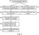
- the EEC 38monitors the engine to detect whether the ignition attempt has been successful and the engine is running. If within ten seconds of the ignition attempt the EEC 38 confirms successful ignition (step 52), normal engine acceleration is scheduled up to an idle speed before the engine in-flight windmill start procedure is ended (step 54) and normal engine running is resumed including standard fuel metering. If, on the other hand, the EEC 38 fails to confirm successful ignition within 10 seconds of the ignition attempt (step 56) a fuel metering valve ramp opening schedule is initiated (step 58).
- FIG. 4An exemplary fuel metering valve ramp opening schedule employed here is shown in Figure 4 .
- the scheduledemands a continuous opening of the fuel metering valve 36 over time.
- the opening of the valvegives rise to an ever increasing over-fuelling fuel metering valve 36 position with respect to a fuel flow necessary for ignition of the engine 10.
- the ever greater opening of the fuel metering valve 36is unlikely to give rise to a corresponding and proportional increase in fuel delivered to the nozzles 40. Nonetheless the ever greater opening of the fuel metering valve 36 tends to reduce the pressure in the fuel system 30 and consequently correspondingly reduce fuel losses to the fueldraulic conduit loops.
- the steady ramping of the opening of the fuel metering valve 36 and periodic ignition attemptsmay mean that the extent of the over-fuelling position is only as substantially great as is necessary in order to provide a sufficient increase in fuel for successful engine 10 ignition. This may be preferable to a rapid and complete opening of the fuel metering valve 36 followed by an engine ignition attempt, as this may unnecessarily increase the degree of over-fuelling subsequent to ignition.
- the shape of the fuel metering valve ramp opening schedulemay have a fixed predetermined shape or may be variable. In the event that the fuel metering valve ramp opening schedule is variable, its shape and particularly its gradient may be determined in accordance with the particular operating conditions of the engine 10. It may be for example that where the engine 10 has a slower airspeed and/or lower altitude, a fuel metering valve ramp opening schedule is calculated by the EEC 38 that requires a more rapid over-fuelling position increase in recognition of the greater likely extent of any shortfall in fuel necessary for ignition.
- a fuel metering pull-off scheduleis invoked (step 62) in place of the fuel metering valve ramp opening schedule.
- An exemplary fuel metering pull-off schedule employed hereis shown in Figure 5 .
- the fuel metering pull-off scheduledetermines the extent of the closing of the fuel metering valve 36 throughout the remainder of the engine in-flight windmill start procedure via EEC 38 control of the fuel metering valve 36.
- the fuel metering pull-off schedulevaries the position of the fuel metering valve 36 in dependence upon a lagged rate of change of the high pressure spool speed.
- the lagged rate of change of the high pressure spool speedis calculated from measured high pressure spool speed, which is then lagged with an appropriate time constant, before finally being differentiated.
- the lagis a convenient way to remove noise on the input signal and therefore provides some damping to avoid large oscillatory behaviour.
- the fuel metering pull-off schedulegenerally reduces fuel delivered as the lagged rate of change of the high pressure spool speed increases. Nonetheless where the lagged rate of change of the high pressure spool speed indicates a relatively slow acceleration of the engine 10 the fuel delivery reduction in accordance with the schedule is lower than where it indicates a relatively rapid acceleration.
- the action of the fuel metering pull-off scheduletends to counteract an over-fuelling condition otherwise tending to result from the over-fuelling position of the fuel metering valve 36 brought about by step 58. Such over-fuelling might otherwise give rise to rapid acceleration of the engine 10, potentially causing a high pressure compressor 15 stall.
- the use of the lagged rate of change of the high pressure spool speed rather than simply the rate of change of the high pressure spool speedhas the advantage that the impact of signal noise is reduced before differentiation of the signal is undertaken.
- the differentiationtends to amplify any oscillatory behaviour, so the pre-lagging of the signal is particularly advantageous.
- step 64The end of the engine in-flight windmill start procedure (step 64) occurs when the engine has accelerated to an idle speed. Thereafter scheduling in dependence upon the lagged rate of change of the high pressure spool speed is ceased (i.e. a delta associated with the fuel metering pull-off scheduling is removed) and standard scheduling is performed.
Landscapes
- Engineering & Computer Science (AREA)
- Chemical & Material Sciences (AREA)
- Combustion & Propulsion (AREA)
- Mechanical Engineering (AREA)
- General Engineering & Computer Science (AREA)
- Combined Controls Of Internal Combustion Engines (AREA)
Description
- The present disclosure concerns a gas turbine engine fuel scheduling. More specifically the disclosure concerns a method of controlling fuel flow for combustion in a gas turbine engine, a controller arranged to perform the method and a gas turbine engine comprising the controller. The disclosure may have particular application to engine in-flight windmill start procedures but is not intended to be limited to such implementations. Indeed the disclosure may have further application in other circumstances, including for instance in fuel flow scheduling during normal operation.
- If it is desired to start an aero gas turbine engine in flight, e.g. following a flameout, a windmill restart is typically attempted. This uses on-rushing air through which the aircraft is passing to windmill the compressors and deliver air to the combustor. A sufficient quantity of fuel must also be delivered to the combustor in order for successful ignition. Fuel is typically pumped to the combustors by a fuel pump driven by a spool powered ancillary gearbox. Under certain flight conditions the windmilling effect of the on-rushing air may turn the relevant spool at a sufficient rate in order to pump sufficient fuel to the combustor for successful start. Where however the flight conditions tend towards a lower airspeed and/or lower altitude (denser air) the rotation rate of the relevant spool as a consequence of windmilling will be lower, and may therefore be insufficient for the delivery of the required quantity of fuel. As will be appreciated this may undesirably mean that as an aircraft descends a pilot is chasing an ever higher airspeed (requiring an ever increasing rate of descent) in order to achieve engine start.
- The problem may be made worse where the fuel pump is deteriorated through in service use and/or fuel is used as a process fluid in other systems, e.g. fueldraulic control of turbine case cooling and/or air control valves. The latter may increase the quantity of fuel 'leaked' to other systems (rather than delivered to the combustor) and reduce spare capacity of the fuel pump. Solutions such as increasing pump capacity and/or other structural changes such as valves for selective isolation of systems using the fuel as a process fluid may be costly and add complexity.
EP2184466 describes a relight method where a nominal fuel delivery setting is higher than a desired fuel delivery rate. However, a further known problem following a successful relight is an over-fuelling of the engine potentially giving rise to a compressor stall. Specifically in order to provide an appropriate quantity of fuel for engine relight, a fuel metering valve may, upon engine re-light, be scheduled more open than is best suited to stable and controlled acceleration towards idle without risk of compressor stall. It is known therefore to reduce over fuelling following light up by scheduling a partial closing of the fuel metering valve. Nonetheless such existing over fuel reduction scheduling is relatively unreliable and unrefined.EP 0 399 692 describes a fuel control system compares the rate of change of a high speed spool with values contained in a datum light-up schedule.- According to a first aspect there is provided a method of controlling fuel flow for combustion in a gas turbine engine comprising a low pressure spool, a high pressure spool and a fuel metering valve, the method comprising scheduling the fuel metering valve in dependence upon a lagged rate of change of the high pressure spool speed, whereby the lagged rate of change of the high pressure spool is calculated from measured high pressure spool speed, which is then lagged with an appropriate time constant, before being differentiated. As will be appreciated the scheduling may further depend on other factors. Furthermore the scheduling may depend upon high pressure spool speed only in particular circumstances (e.g. when the engine is operating in a particular manner or regime e.g. transient operation or during an engine start and initial acceleration procedure).
- Scheduling fuel metering in dependence upon the speed of the high pressure spool may help to prevent over fuelling of the engine and consequent increased risk of stall of a high pressure compressor of the high pressure spool. The scheduling may for instance mean that additional fuel is delivered only when sufficient high pressure compressor stall margin is available. Further, it may be that a fuel pump of the engine is driven by an alternative spool to the high pressure spool. In such cases, scheduling in dependence on the speed of the high pressure spool rather than the speed of a spool driving the fuel pump may mean that there is no need to tailor the scheduling to the specific design and characteristics of the fuel pump. In this way, alterations to the fuel pump used may be immaterial in terms of the scheduling used and the scheduling may be applicable across different fleets of engines despite each fleet employing a fuel pump design having different characteristics.
- In some embodiments the method comprises scheduling the fuel metering valve to an over-fuelling position with respect to a fuel flow necessary for ignition of the engine prior to an attempted ignition during an engine in-flight windmill start procedure. It may be that the over-fuelling position of the fuel metering valve exceeds the fuel supply deliverable by the fuel pump at that time. This may in occur in particular because the engine is windmilling and so the fuel pump is driven only by a windmilling spool,With the fuel metering valve no longer giving rise to a pressure drop, the pressure in a fuel system for the engine may be reduced. Consequently any parasitic fuel losses to other systems which use the fuel as a process fluid may be reduced. The reduction in parasitic fuel losses may increase fuel flow to a combustor of the engine to (or nearer to) a nominal level of fuel that would be necessary in order to sustain combustion with the engine running at the windmill speed. As will be appreciated this method allows for a potential increase in fuel delivery to the combustor during an engine in-flight windmill start procedure for a given fuel pump capacity. Further this is achieved without the need for a structural/architectural change to the engine.
- In some embodiments the scheduling of the fuel metering valve to an over-fuelling position is employed following a failed ignition attempt during the in-flight engine windmill start procedure. Additionally or alternatively the scheduling of the fuel metering valve to an over-fuelling position may be employed where the engine is operating in a particular regime (e.g. ambient airspeed and pressure meet particular criteria). Additionally or alternatively the elapse of a particular time (e.g. approximately 10 seconds) during which successful ignition has not occurred may be a criteria for employment of the over-fuelling position. Any of these conditions may be used as indicative of a requirement for an increase in fuel flow for successful ignition to occur.
- In some embodiments the position of the fuel metering valve is scheduled such that the degree of over-fuelling corresponding thereto is increased over time. It may be for instance that the fuel metering valve is progressively opened (either in discrete steps or continuously) over a given period. As will be appreciated the rate of such a change may be constant or may vary. It may be that the rate of change is determined in accordance with the fuel metering valve position that will achieve the minimum combustor fuel flow required to attain ignition for an end of life fuel pump as well as a predetermined period in which this condition should be reached. As will be appreciated the ramping of the fuel metering valve may mean that fuel is delivered in increasing quantities only to a level that is necessary. This may help to avoid over fuelling and high pressure compressor stall following successful engine ignition.
- In some embodiments the rate of increase is scheduled in dependence upon the speed of the high pressure spool, optionally more specifically the rate of change of the high pressure spool speed and optionally still more specifically a lagged rate of change of the high pressure spool speed. Factoring in the high pressure spool speed may allow better protection of the high pressure compressor stall margin whilst the fuel metering valve is scheduled for over-fuelling and before engine ignition.
- In some embodiments scheduling in dependence upon the speed of the high pressure spool is employed during engine acceleration. In the context of engine acceleration the method may offer an advantageous solution for scheduling a controlled and stable acceleration and reducing the likelihood of a high pressure compressor stall.
- In some embodiments scheduling in dependence upon the speed of the high pressure spool is employed during engine acceleration from ignition.
- In some embodiments scheduling in dependence upon the speed of the high pressure spool is employed during engine acceleration from ignition occurring during an in-flight engine windmill start procedure. The engine may be particularly vulnerable to high pressure compressor stall during initial engine acceleration following a windmill start procedure ignition, especially where the fuel metering valve is initially set to an over-fuelling position in order to increase fuel flow and assist ignition.
- In some embodiments scheduling of the fuel metering valve in dependence upon the speed of the high pressure spool is more specifically in dependence upon the rate of change of the high pressure spool speed. The rate of change of the high pressure spool speed may be a good indicator of high pressure compressor stall margin.
- The scheduling of the fuel metering valve in dependence upon the rate of change of the high pressure spool speed is in dependence upon a lagged rate of change of the high pressure spool speed. The introduction of the lag may reduce the impact of noise and anomalies in a determined high pressure spool speed.
- In some embodiments the fuel metering valve is scheduled to move from a more open position to a more closed position, whereby the extent and/or rate of its closing is dependent on the lagged rate of change of the high pressure spool speed. Closing somewhat the fuel metering valve may reduce the rate of acceleration of the engine and may therefore prevent a high pressure compressor stall. By accounting for the lagged rate of change of the high pressure spool speed, a proportionate extent and/or rate of fuel metering valve closure may be selected.
- In some embodiments the method comprises scheduling the fuel metering valve such that there is a decreased or zero rate of closing where the lagged rate of change of the high pressure spool speed is below a threshold and an increased rate of closing when it is above the threshold. Such scheduling may allow a relatively unhindered initial acceleration of the engine following an in-flight engine windmill start procedure ignition. This may allow the fuel delivered to reach more quickly a nominal delivery expected for the engine windmill rate had the engine been running normally at that rate. It may also reduce the likelihood of engine flameout shortly after ignition as a consequence of fuel starvation. Thereafter an increased rate of closing may prevent rapid acceleration caused by over-fuelling, particularly where the fuel metering valve has been scheduled to an over-fuel position to assist ignition. Once the start procedure is complete, with an initial stable acceleration achieved, conventional scheduling of the fuel metering valve may be undertaken without the lagged rate of change of the high pressure spool speed acting as a control parameter. Alternatively the lagged rate of change of the high pressure spool speed may continue to be used as a parameter in scheduling of the fuel metering valve.
- According to a second aspect there is provided a gas turbine engine comprising a low pressure spool, a high pressure spool, a fuel metering valve and a fuel flow controller, the controller being arranged in use to schedule the fuel metering valve in dependence upon the speed of the high pressure spool, whereby the lagged rate of change of the high pressure spool is calculated from measured high pressure spool speed, which is then lagged with an appropriate time constant, before being differentiated.
- According to a third aspect there is provided a gas turbine engine fuel flow controller arranged for use in a gas turbine engine having a low pressure spool, a high pressure spool and a fuel metering valve, the controller being arranged in use to schedule the fuel metering valve in dependence upon the speed of the high pressure spool, whereby the lagged rate of change of the high pressure spool is calculated from measured high pressure spool speed, which is then lagged with an appropriate time constant, before being differentiated.
- Embodiments of the invention will now be described by way of example only, with reference to the Figures, in which:
Figure 1 is a sectional side view of a gas turbine engine;Figure 2 is a schematic view of a gas turbine engine fuel system;Figure 3 is flow diagram showing an engine in-flight windmill start procedure in accordance with an embodiment of the invention;Figure 4 is an exemplary fuel metering valve ramp opening schedule in accordance with an embodiment of the invention;Figure 5 is an exemplary fuel metering pull-off schedule in accordance with an embodiment of the invention.- With reference to
Figure 1 , a gas turbine engine is generally indicated at 10, having a principal androtational axis 11. Theengine 10 comprises, in axial flow series, anair intake 12, apropulsive fan 13, anintermediate pressure compressor 14, a high-pressure compressor 15,combustion equipment 16, a high-pressure turbine 17, anintermediate pressure turbine 18, a low-pressure turbine 19 and anexhaust nozzles 20. Anacelle 21 generally surrounds theengine 10 and defines both theintake 12 and theexhaust nozzles 20. - The
gas turbine engine 10 works in the conventional manner so that air entering theintake 12 is accelerated by thefan 13 to produce two air flows: a first air flow into theintermediate pressure compressor 14 and a second air flow which passes through abypass duct 22 to provide propulsive thrust. Theintermediate pressure compressor 14 compresses the air flow directed into it before delivering that air to thehigh pressure compressor 15 where further compression takes place. - The compressed air exhausted from the high-
pressure compressor 15 is directed into thecombustion equipment 16 where it is mixed with fuel and the mixture combusted. The resultant hot combustion products then expand through, and thereby drive the high, intermediate and low-pressure turbines nozzles 20 to provide additional propulsive thrust. The high 17, intermediate 18 and low 19 pressure turbines drive respectively thehigh pressure compressor 15,intermediate pressure compressor 14 andfan 13, each by suitable interconnecting shaft. Thehigh pressure compressor 15,turbine 17 and interconnecting shaft form a high pressure spool, theintermediate pressure compressor 14,turbine 18 and interconnecting shaft form an intermediate pressure spool and thefan 13,low pressure turbine 19 and interconnecting shaft form a low pressure spool. - Referring now to
Figure 2 , parts of a fuel system for theengine 10, generally shown at 30, are discussed. Thefuel system 30 comprises afuel tank 32, afuel pump 34, afuel metering valve 36, a fuel flow controller (in this case an engine electronic controller (EEC) 38 of a full authority digital engine control (FADEC)) and combustorfuel spray nozzles 40. Thefuel tank 32,fuel pump 34,fuel metering valve 36 andnozzles 40 are connected in series byfuel conduits 42. Afuel return loop 43 is also provided to spill excess fuel back to thefuel tank 32. Additional fueldraulic conduit loops (not shown) branch off from thefuel conduits 42 upstream of thefuel metering valve 36 for delivery of fuel for use inadditional engine 10 components. Thefuel pump 34 is connected to and in use is driven by the intermediate pressure spool (although in alternative embodiments the fuel pump is connected to and in use is driven by the high pressure spool). The connection between thefuel pump 34 and intermediate pressure spool is via an ancillary gearbox (not shown). In use of thefuel system 30, thefuel pump 34, driven by the intermediate pressure spool, delivers fuel from thefuel tank 32 to the fueldraulic conduit loops as well as to thenozzles 40 via thefuel metering valve 36. TheEEC 38 controls thefuel metering valve 36 position (and so fuel delivery to the nozzles 40) in accordance with a thrust demand (selected for example via a cockpit power lever) and one or more fuel metering schedules. Fuel metering schedules are used to trim fuel metering, particularly where the engine is operating under certain conditions and/or in certain regimes. - Referring now to
Figure 3 , an engine in-flight windmill start procedure suitable for an engine as previously discussed with respect toFigures 1 and 2 is explained. Under windmill conditions theengine 10 is not running. Nonetheless on-rushing air passing through theengine 10 turns the low, intermediate and high pressure spools. As a consequence of this windmill turning of the intermediate pressure spool, thefuel pump 34 is operated and can deliver fuel to thenozzles 40 under the control of thefuel metering valve 36 as well as to the fueldraulic conduit loops. As will be appreciated however the fuel deliverable by thepump 34 is relatively low as a consequence of the relatively slow windmill speed of the intermediate pressure spool. Furthermore as ambient air pressure increases (associated with lower altitude operation) and/orengine 10 airspeed drops, the windmill speed of the intermediate pressure spool will decrease, reducing further the fuel deliverable by thefuel pump 34 to thenozzles 40. - With sufficient altitude and/or airspeed, sufficient fuel may be deliverable to the
nozzles 40 for ignition and initial acceleration of theengine 10 without additional fuel delivery assistance. Thus as aninitial step 50 of the engine in-flight windmill start procedure, theEEC 38 initiates an engine ignition attempt. TheEEC 38 then monitors the engine to detect whether the ignition attempt has been successful and the engine is running. If within ten seconds of the ignition attempt theEEC 38 confirms successful ignition (step 52), normal engine acceleration is scheduled up to an idle speed before the engine in-flight windmill start procedure is ended (step 54) and normal engine running is resumed including standard fuel metering. If, on the other hand, theEEC 38 fails to confirm successful ignition within 10 seconds of the ignition attempt (step 56) a fuel metering valve ramp opening schedule is initiated (step 58). - An exemplary fuel metering valve ramp opening schedule employed here is shown in
Figure 4 . The schedule demands a continuous opening of thefuel metering valve 36 over time. The opening of the valve gives rise to an ever increasing over-fuellingfuel metering valve 36 position with respect to a fuel flow necessary for ignition of theengine 10. Because relatively slow operation of thefuel pump 34 is the principle limiting factor in the fuel deliverable to thenozzles 40, the ever greater opening of thefuel metering valve 36 is unlikely to give rise to a corresponding and proportional increase in fuel delivered to thenozzles 40. Nonetheless the ever greater opening of thefuel metering valve 36 tends to reduce the pressure in thefuel system 30 and consequently correspondingly reduce fuel losses to the fueldraulic conduit loops. This in turn increases the proportion of the fuel pumped by thefuel pump 34 that is delivered to thenozzles 40. As the fuel metering ramp opening schedule is invoked, successive engine ignition attempts are initiated at intervals until successful ignition is confirmed by the EEC 38 (step 60). It may therefore be that anywhere from one to several additional engine ignition attempts are necessary. - The steady ramping of the opening of the
fuel metering valve 36 and periodic ignition attempts may mean that the extent of the over-fuelling position is only as substantially great as is necessary in order to provide a sufficient increase in fuel forsuccessful engine 10 ignition. This may be preferable to a rapid and complete opening of thefuel metering valve 36 followed by an engine ignition attempt, as this may unnecessarily increase the degree of over-fuelling subsequent to ignition. - The shape of the fuel metering valve ramp opening schedule may have a fixed predetermined shape or may be variable. In the event that the fuel metering valve ramp opening schedule is variable, its shape and particularly its gradient may be determined in accordance with the particular operating conditions of the
engine 10. It may be for example that where theengine 10 has a slower airspeed and/or lower altitude, a fuel metering valve ramp opening schedule is calculated by theEEC 38 that requires a more rapid over-fuelling position increase in recognition of the greater likely extent of any shortfall in fuel necessary for ignition. - Once the
EEC 38 has confirmedsuccessful engine 10 ignition a fuel metering pull-off schedule is invoked (step 62) in place of the fuel metering valve ramp opening schedule. An exemplary fuel metering pull-off schedule employed here is shown inFigure 5 . The fuel metering pull-off schedule determines the extent of the closing of thefuel metering valve 36 throughout the remainder of the engine in-flight windmill start procedure viaEEC 38 control of thefuel metering valve 36. - The fuel metering pull-off schedule varies the position of the
fuel metering valve 36 in dependence upon a lagged rate of change of the high pressure spool speed. The lagged rate of change of the high pressure spool speed is calculated from measured high pressure spool speed, which is then lagged with an appropriate time constant, before finally being differentiated. The lag is a convenient way to remove noise on the input signal and therefore provides some damping to avoid large oscillatory behaviour. - The fuel metering pull-off schedule generally reduces fuel delivered as the lagged rate of change of the high pressure spool speed increases. Nonetheless where the lagged rate of change of the high pressure spool speed indicates a relatively slow acceleration of the
engine 10 the fuel delivery reduction in accordance with the schedule is lower than where it indicates a relatively rapid acceleration. The action of the fuel metering pull-off schedule tends to counteract an over-fuelling condition otherwise tending to result from the over-fuelling position of thefuel metering valve 36 brought about bystep 58. Such over-fuelling might otherwise give rise to rapid acceleration of theengine 10, potentially causing ahigh pressure compressor 15 stall. By linking thefuel metering valve 36 position during initial acceleration to the rate of change of the high pressure spool speed, high pressure compressor stall may be avoided whilst allowing theengine 10 to accelerate following ignition. Furthermore the relatively restrained closing of thefuel metering valve 36 dictated by the fuel metering pull-off schedule where theengine 10 is accelerating relatively slowly (e.g. immediately after ignition) may allow fuel delivered to reach more quickly a nominal delivery expected for the engine windmill rate had theengine 10 been running normally at that rate. - The use of the lagged rate of change of the high pressure spool speed rather than simply the rate of change of the high pressure spool speed has the advantage that the impact of signal noise is reduced before differentiation of the signal is undertaken. The differentiation tends to amplify any oscillatory behaviour, so the pre-lagging of the signal is particularly advantageous.
- The end of the engine in-flight windmill start procedure (step 64) occurs when the engine has accelerated to an idle speed. Thereafter scheduling in dependence upon the lagged rate of change of the high pressure spool speed is ceased (i.e. a delta associated with the fuel metering pull-off scheduling is removed) and standard scheduling is performed.
- It will be understood that the invention is not limited to the embodiments above-described and various modifications and improvements can be made without departing from the concepts described herein.
Claims (11)
- A method of controlling fuel flow for combustion in a gas turbine engine (10) comprising a low pressure spool (13,19), a high pressure spool (15, 17) and a fuel metering valve (36),characterised in that the method comprises scheduling the fuel metering valve in dependence upon a lagged rate of change of the high pressure spool speed, whereby the lagged rate of change of the high pressure spool is calculated from measured high pressure spool speed, which is then lagged with an appropriate time constant, before being differentiated.
- The method according to claim 1 further comprising scheduling the fuel metering valve (36) to an over-fuelling position with respect to a fuel flow necessary for ignition of the gas turbine engine (10) prior to an attempted ignition during an engine in-flight windmill start procedure.
- The method according to claim 2 where the scheduling of the fuel metering valve (36) to an over-fuelling position is employed following a failed ignition attempt during the engine in-flight windmill start procedure.
- The method according to claim 2 or claim 3 where the position of the fuel metering valve (36) is scheduled such that the degree of over-fuelling corresponding thereto is increased over time.
- The method according to any preceding claim where the scheduling in dependence upon the speed of the high pressure spool is employed during engine acceleration.
- The method according to any preceding claim where the scheduling in dependence upon the speed of the high pressure spool (15, 17) is employed during engine acceleration from ignition.
- The method according to any preceding claim where the scheduling in dependence upon the speed of the high pressure spool (15, 17) is employed during engine acceleration from ignition occurring during an in-flight engine windmill start procedure.
- The method according to any preceding claim where the fuel metering valve (36) is scheduled to move from a more open position to a more closed position, whereby the extent and/or rate of its closing is dependent on the lagged rate of change of the high pressure spool speed.
- The method according to any preceding claim where scheduling the fuel metering valve (36) such that there is a decreased or zero rate of closing where the lagged rate of change of the high pressure spool speed is below a threshold and an increased rate of closing when it is above the threshold.
- A gas turbine engine fuel flow controller arranged for use in a gas turbine engine having a low pressure spool, a high pressure spool and a fuel metering valve,characterised in that the fuel flow controller is arranged in use to schedule the fuel metering valve in dependence upon a lagged rate of change of the high pressure spool speed, whereby the lagged rate of change of the high pressure spool is calculated from measured high pressure spool speed, which is then lagged with an appropriate time constant, before being differentiated.
- A gas turbine engine having a gas turbine engine fuel flow controller according to claim 10.
Applications Claiming Priority (1)
| Application Number | Priority Date | Filing Date | Title |
|---|---|---|---|
| GBGB1512414.2AGB201512414D0 (en) | 2015-07-16 | 2015-07-16 | Gas turbine engine fuel scheduling |
Publications (2)
| Publication Number | Publication Date |
|---|---|
| EP3118437A1 EP3118437A1 (en) | 2017-01-18 |
| EP3118437B1true EP3118437B1 (en) | 2021-02-24 |
Family
ID=54014024
Family Applications (1)
| Application Number | Title | Priority Date | Filing Date |
|---|---|---|---|
| EP16175261.3AActiveEP3118437B1 (en) | 2015-07-16 | 2016-06-20 | Gas turbine engine fuel scheduling |
Country Status (3)
| Country | Link |
|---|---|
| US (1) | US20170016401A1 (en) |
| EP (1) | EP3118437B1 (en) |
| GB (1) | GB201512414D0 (en) |
Families Citing this family (7)
| Publication number | Priority date | Publication date | Assignee | Title |
|---|---|---|---|---|
| CN108146343B (en)* | 2016-12-02 | 2021-01-05 | 财团法人资讯工业策进会 | Early warning system and early warning method |
| US10801416B2 (en)* | 2017-05-03 | 2020-10-13 | Pratt & Whitney Canada Corp. | Method and system for setting fuel flow for engine start as a function of aircraft speed |
| GB201801704D0 (en) | 2018-02-02 | 2018-03-21 | Rolls Royce Plc | Fuel flow valve |
| US11578661B2 (en) | 2019-09-19 | 2023-02-14 | Pratt & Whitney Canada Corp. | Systems and methods for starting a gas turbine engine |
| US20220178544A1 (en)* | 2020-12-09 | 2022-06-09 | Pratt & Whitney Canada Corp. | Method of operating an aircraft engine and fuel system using multiple fuel types |
| US12000341B1 (en) | 2023-01-16 | 2024-06-04 | Pratt & Whitney Canada Corp. | Method for starting an auxiliary power unit |
| GB202319150D0 (en) | 2023-12-14 | 2024-01-31 | Rolls Royce Plc | Fueldraulic heat management system |
Citations (1)
| Publication number | Priority date | Publication date | Assignee | Title |
|---|---|---|---|---|
| US3811273A (en)* | 1973-03-08 | 1974-05-21 | United Aircraft Corp | Slaved fuel control for multi-engined aircraft |
Family Cites Families (8)
| Publication number | Priority date | Publication date | Assignee | Title |
|---|---|---|---|---|
| US4062185A (en)* | 1976-05-13 | 1977-12-13 | General Electric Company | Method and apparatus for windmill starts in gas turbine engines |
| GB8911806D0 (en)* | 1989-05-23 | 1989-07-12 | Rolls Royce Plc | Gas turbine engine fuel control system with enhanced relight capability |
| US5907949A (en)* | 1997-02-03 | 1999-06-01 | United Technologies Corporation | Starting fuel control method for a turbine engine |
| US6062016A (en)* | 1997-04-21 | 2000-05-16 | Capstone Turbine Corporation | Gas turbine engine fixed speed light-off method |
| GB9727157D0 (en)* | 1997-12-24 | 1998-02-25 | Lucas Ind Plc | Fuel system for a gas turbine engine |
| GB0401207D0 (en)* | 2004-01-21 | 2004-02-25 | Goodrich Control Sys Ltd | Fuel supply system |
| GB0820410D0 (en)* | 2008-11-07 | 2008-12-17 | Goodrich Control Sys Ltd | Engine relight method |
| GB201313142D0 (en)* | 2013-07-23 | 2013-09-04 | Rolls Royce Engine Control Systems Ltd | Engine Fuel Control System |
- 2015
- 2015-07-16GBGBGB1512414.2Apatent/GB201512414D0/ennot_activeCeased
- 2016
- 2016-06-20USUS15/186,805patent/US20170016401A1/ennot_activeAbandoned
- 2016-06-20EPEP16175261.3Apatent/EP3118437B1/enactiveActive
Patent Citations (1)
| Publication number | Priority date | Publication date | Assignee | Title |
|---|---|---|---|---|
| US3811273A (en)* | 1973-03-08 | 1974-05-21 | United Aircraft Corp | Slaved fuel control for multi-engined aircraft |
Also Published As
| Publication number | Publication date |
|---|---|
| EP3118437A1 (en) | 2017-01-18 |
| GB201512414D0 (en) | 2015-08-19 |
| US20170016401A1 (en) | 2017-01-19 |
Similar Documents
| Publication | Publication Date | Title |
|---|---|---|
| EP3118437B1 (en) | Gas turbine engine fuel scheduling | |
| EP3073122B1 (en) | Aero gas turbine engine with compressor and associated method | |
| EP3473842B1 (en) | Electric cruise pump system | |
| EP2884075B1 (en) | Aircraft engine system comprising a main engine, a starter and an auxiliary power unit | |
| US5235812A (en) | Integrated power unit | |
| EP2133537B1 (en) | Bi-modal air turbine starter assembly | |
| US11506128B2 (en) | Hydraulic starter assembly for a gas turbine engine | |
| US12018616B2 (en) | Systems and methods for purging a fuel manifold of a gas turbine engine | |
| EP2952719B1 (en) | A method of determining a fault within a flow divider | |
| US5097658A (en) | Integrated power unit control apparatus and method | |
| US20100121553A1 (en) | Engine Relight Method | |
| WO1991004397A1 (en) | Integrated power unit control apparatus and method | |
| EP3770404B1 (en) | Fuel delivery system and method | |
| EP3770406B1 (en) | Fuel delivery system and method | |
| US5161363A (en) | Integrated power unit | |
| EP3054124B1 (en) | Accumulator assisted gas turbine engine start system and methods therefor | |
| EP3770405B1 (en) | Fuel delivery system and method | |
| US20230057599A1 (en) | Start-up sequence for gaseous fuel engine | |
| US5160069A (en) | Integrated power unit combustion apparatus and method | |
| US9926848B2 (en) | Turbomachine fuel delivery method and assembly | |
| GB2192670A (en) | Fuel control system for gas turbine engines |
Legal Events
| Date | Code | Title | Description |
|---|---|---|---|
| PUAI | Public reference made under article 153(3) epc to a published international application that has entered the european phase | Free format text:ORIGINAL CODE: 0009012 | |
| STAA | Information on the status of an ep patent application or granted ep patent | Free format text:STATUS: THE APPLICATION HAS BEEN PUBLISHED | |
| AK | Designated contracting states | Kind code of ref document:A1 Designated state(s):AL AT BE BG CH CY CZ DE DK EE ES FI FR GB GR HR HU IE IS IT LI LT LU LV MC MK MT NL NO PL PT RO RS SE SI SK SM TR | |
| AX | Request for extension of the european patent | Extension state:BA ME | |
| STAA | Information on the status of an ep patent application or granted ep patent | Free format text:STATUS: REQUEST FOR EXAMINATION WAS MADE | |
| 17P | Request for examination filed | Effective date:20170710 | |
| RBV | Designated contracting states (corrected) | Designated state(s):AL AT BE BG CH CY CZ DE DK EE ES FI FR GB GR HR HU IE IS IT LI LT LU LV MC MK MT NL NO PL PT RO RS SE SI SK SM TR | |
| STAA | Information on the status of an ep patent application or granted ep patent | Free format text:STATUS: EXAMINATION IS IN PROGRESS | |
| 17Q | First examination report despatched | Effective date:20191216 | |
| RAP1 | Party data changed (applicant data changed or rights of an application transferred) | Owner name:ROLLS-ROYCE PLC | |
| GRAP | Despatch of communication of intention to grant a patent | Free format text:ORIGINAL CODE: EPIDOSNIGR1 | |
| STAA | Information on the status of an ep patent application or granted ep patent | Free format text:STATUS: GRANT OF PATENT IS INTENDED | |
| INTG | Intention to grant announced | Effective date:20201215 | |
| GRAS | Grant fee paid | Free format text:ORIGINAL CODE: EPIDOSNIGR3 | |
| GRAA | (expected) grant | Free format text:ORIGINAL CODE: 0009210 | |
| STAA | Information on the status of an ep patent application or granted ep patent | Free format text:STATUS: THE PATENT HAS BEEN GRANTED | |
| AK | Designated contracting states | Kind code of ref document:B1 Designated state(s):AL AT BE BG CH CY CZ DE DK EE ES FI FR GB GR HR HU IE IS IT LI LT LU LV MC MK MT NL NO PL PT RO RS SE SI SK SM TR | |
| REG | Reference to a national code | Ref country code:CH Ref legal event code:EP | |
| REG | Reference to a national code | Ref country code:AT Ref legal event code:REF Ref document number:1364716 Country of ref document:AT Kind code of ref document:T Effective date:20210315 | |
| REG | Reference to a national code | Ref country code:IE Ref legal event code:FG4D | |
| REG | Reference to a national code | Ref country code:DE Ref legal event code:R096 Ref document number:602016052981 Country of ref document:DE | |
| REG | Reference to a national code | Ref country code:LT Ref legal event code:MG9D | |
| REG | Reference to a national code | Ref country code:NL Ref legal event code:MP Effective date:20210224 | |
| PG25 | Lapsed in a contracting state [announced via postgrant information from national office to epo] | Ref country code:NO Free format text:LAPSE BECAUSE OF FAILURE TO SUBMIT A TRANSLATION OF THE DESCRIPTION OR TO PAY THE FEE WITHIN THE PRESCRIBED TIME-LIMIT Effective date:20210524 Ref country code:PT Free format text:LAPSE BECAUSE OF FAILURE TO SUBMIT A TRANSLATION OF THE DESCRIPTION OR TO PAY THE FEE WITHIN THE PRESCRIBED TIME-LIMIT Effective date:20210624 Ref country code:GR Free format text:LAPSE BECAUSE OF FAILURE TO SUBMIT A TRANSLATION OF THE DESCRIPTION OR TO PAY THE FEE WITHIN THE PRESCRIBED TIME-LIMIT Effective date:20210525 Ref country code:HR Free format text:LAPSE BECAUSE OF FAILURE TO SUBMIT A TRANSLATION OF THE DESCRIPTION OR TO PAY THE FEE WITHIN THE PRESCRIBED TIME-LIMIT Effective date:20210224 Ref country code:FI Free format text:LAPSE BECAUSE OF FAILURE TO SUBMIT A TRANSLATION OF THE DESCRIPTION OR TO PAY THE FEE WITHIN THE PRESCRIBED TIME-LIMIT Effective date:20210224 Ref country code:LT Free format text:LAPSE BECAUSE OF FAILURE TO SUBMIT A TRANSLATION OF THE DESCRIPTION OR TO PAY THE FEE WITHIN THE PRESCRIBED TIME-LIMIT Effective date:20210224 Ref country code:BG Free format text:LAPSE BECAUSE OF FAILURE TO SUBMIT A TRANSLATION OF THE DESCRIPTION OR TO PAY THE FEE WITHIN THE PRESCRIBED TIME-LIMIT Effective date:20210524 | |
| REG | Reference to a national code | Ref country code:AT Ref legal event code:MK05 Ref document number:1364716 Country of ref document:AT Kind code of ref document:T Effective date:20210224 | |
| PG25 | Lapsed in a contracting state [announced via postgrant information from national office to epo] | Ref country code:LV Free format text:LAPSE BECAUSE OF FAILURE TO SUBMIT A TRANSLATION OF THE DESCRIPTION OR TO PAY THE FEE WITHIN THE PRESCRIBED TIME-LIMIT Effective date:20210224 Ref country code:NL Free format text:LAPSE BECAUSE OF FAILURE TO SUBMIT A TRANSLATION OF THE DESCRIPTION OR TO PAY THE FEE WITHIN THE PRESCRIBED TIME-LIMIT Effective date:20210224 Ref country code:PL Free format text:LAPSE BECAUSE OF FAILURE TO SUBMIT A TRANSLATION OF THE DESCRIPTION OR TO PAY THE FEE WITHIN THE PRESCRIBED TIME-LIMIT Effective date:20210224 Ref country code:RS Free format text:LAPSE BECAUSE OF FAILURE TO SUBMIT A TRANSLATION OF THE DESCRIPTION OR TO PAY THE FEE WITHIN THE PRESCRIBED TIME-LIMIT Effective date:20210224 Ref country code:SE Free format text:LAPSE BECAUSE OF FAILURE TO SUBMIT A TRANSLATION OF THE DESCRIPTION OR TO PAY THE FEE WITHIN THE PRESCRIBED TIME-LIMIT Effective date:20210224 | |
| PG25 | Lapsed in a contracting state [announced via postgrant information from national office to epo] | Ref country code:IS Free format text:LAPSE BECAUSE OF FAILURE TO SUBMIT A TRANSLATION OF THE DESCRIPTION OR TO PAY THE FEE WITHIN THE PRESCRIBED TIME-LIMIT Effective date:20210624 | |
| PG25 | Lapsed in a contracting state [announced via postgrant information from national office to epo] | Ref country code:CZ Free format text:LAPSE BECAUSE OF FAILURE TO SUBMIT A TRANSLATION OF THE DESCRIPTION OR TO PAY THE FEE WITHIN THE PRESCRIBED TIME-LIMIT Effective date:20210224 Ref country code:EE Free format text:LAPSE BECAUSE OF FAILURE TO SUBMIT A TRANSLATION OF THE DESCRIPTION OR TO PAY THE FEE WITHIN THE PRESCRIBED TIME-LIMIT Effective date:20210224 Ref country code:AT Free format text:LAPSE BECAUSE OF FAILURE TO SUBMIT A TRANSLATION OF THE DESCRIPTION OR TO PAY THE FEE WITHIN THE PRESCRIBED TIME-LIMIT Effective date:20210224 Ref country code:SM Free format text:LAPSE BECAUSE OF FAILURE TO SUBMIT A TRANSLATION OF THE DESCRIPTION OR TO PAY THE FEE WITHIN THE PRESCRIBED TIME-LIMIT Effective date:20210224 | |
| REG | Reference to a national code | Ref country code:DE Ref legal event code:R097 Ref document number:602016052981 Country of ref document:DE | |
| PG25 | Lapsed in a contracting state [announced via postgrant information from national office to epo] | Ref country code:ES Free format text:LAPSE BECAUSE OF FAILURE TO SUBMIT A TRANSLATION OF THE DESCRIPTION OR TO PAY THE FEE WITHIN THE PRESCRIBED TIME-LIMIT Effective date:20210224 Ref country code:DK Free format text:LAPSE BECAUSE OF FAILURE TO SUBMIT A TRANSLATION OF THE DESCRIPTION OR TO PAY THE FEE WITHIN THE PRESCRIBED TIME-LIMIT Effective date:20210224 Ref country code:RO Free format text:LAPSE BECAUSE OF FAILURE TO SUBMIT A TRANSLATION OF THE DESCRIPTION OR TO PAY THE FEE WITHIN THE PRESCRIBED TIME-LIMIT Effective date:20210224 Ref country code:SK Free format text:LAPSE BECAUSE OF FAILURE TO SUBMIT A TRANSLATION OF THE DESCRIPTION OR TO PAY THE FEE WITHIN THE PRESCRIBED TIME-LIMIT Effective date:20210224 | |
| PLBE | No opposition filed within time limit | Free format text:ORIGINAL CODE: 0009261 | |
| STAA | Information on the status of an ep patent application or granted ep patent | Free format text:STATUS: NO OPPOSITION FILED WITHIN TIME LIMIT | |
| PG25 | Lapsed in a contracting state [announced via postgrant information from national office to epo] | Ref country code:MC Free format text:LAPSE BECAUSE OF FAILURE TO SUBMIT A TRANSLATION OF THE DESCRIPTION OR TO PAY THE FEE WITHIN THE PRESCRIBED TIME-LIMIT Effective date:20210224 Ref country code:AL Free format text:LAPSE BECAUSE OF FAILURE TO SUBMIT A TRANSLATION OF THE DESCRIPTION OR TO PAY THE FEE WITHIN THE PRESCRIBED TIME-LIMIT Effective date:20210224 | |
| REG | Reference to a national code | Ref country code:CH Ref legal event code:PL | |
| 26N | No opposition filed | Effective date:20211125 | |
| PG25 | Lapsed in a contracting state [announced via postgrant information from national office to epo] | Ref country code:SI Free format text:LAPSE BECAUSE OF FAILURE TO SUBMIT A TRANSLATION OF THE DESCRIPTION OR TO PAY THE FEE WITHIN THE PRESCRIBED TIME-LIMIT Effective date:20210224 | |
| REG | Reference to a national code | Ref country code:BE Ref legal event code:MM Effective date:20210630 | |
| PG25 | Lapsed in a contracting state [announced via postgrant information from national office to epo] | Ref country code:LU Free format text:LAPSE BECAUSE OF NON-PAYMENT OF DUE FEES Effective date:20210620 | |
| PG25 | Lapsed in a contracting state [announced via postgrant information from national office to epo] | Ref country code:LI Free format text:LAPSE BECAUSE OF NON-PAYMENT OF DUE FEES Effective date:20210630 Ref country code:IT Free format text:LAPSE BECAUSE OF FAILURE TO SUBMIT A TRANSLATION OF THE DESCRIPTION OR TO PAY THE FEE WITHIN THE PRESCRIBED TIME-LIMIT Effective date:20210224 Ref country code:IE Free format text:LAPSE BECAUSE OF NON-PAYMENT OF DUE FEES Effective date:20210620 Ref country code:CH Free format text:LAPSE BECAUSE OF NON-PAYMENT OF DUE FEES Effective date:20210630 | |
| PG25 | Lapsed in a contracting state [announced via postgrant information from national office to epo] | Ref country code:IS Free format text:LAPSE BECAUSE OF FAILURE TO SUBMIT A TRANSLATION OF THE DESCRIPTION OR TO PAY THE FEE WITHIN THE PRESCRIBED TIME-LIMIT Effective date:20210624 | |
| PG25 | Lapsed in a contracting state [announced via postgrant information from national office to epo] | Ref country code:BE Free format text:LAPSE BECAUSE OF NON-PAYMENT OF DUE FEES Effective date:20210630 | |
| PG25 | Lapsed in a contracting state [announced via postgrant information from national office to epo] | Ref country code:HU Free format text:LAPSE BECAUSE OF FAILURE TO SUBMIT A TRANSLATION OF THE DESCRIPTION OR TO PAY THE FEE WITHIN THE PRESCRIBED TIME-LIMIT; INVALID AB INITIO Effective date:20160620 | |
| PG25 | Lapsed in a contracting state [announced via postgrant information from national office to epo] | Ref country code:CY Free format text:LAPSE BECAUSE OF FAILURE TO SUBMIT A TRANSLATION OF THE DESCRIPTION OR TO PAY THE FEE WITHIN THE PRESCRIBED TIME-LIMIT Effective date:20210224 | |
| P01 | Opt-out of the competence of the unified patent court (upc) registered | Effective date:20230528 | |
| PG25 | Lapsed in a contracting state [announced via postgrant information from national office to epo] | Ref country code:MK Free format text:LAPSE BECAUSE OF FAILURE TO SUBMIT A TRANSLATION OF THE DESCRIPTION OR TO PAY THE FEE WITHIN THE PRESCRIBED TIME-LIMIT Effective date:20210224 | |
| PG25 | Lapsed in a contracting state [announced via postgrant information from national office to epo] | Ref country code:TR Free format text:LAPSE BECAUSE OF FAILURE TO SUBMIT A TRANSLATION OF THE DESCRIPTION OR TO PAY THE FEE WITHIN THE PRESCRIBED TIME-LIMIT Effective date:20210224 | |
| PG25 | Lapsed in a contracting state [announced via postgrant information from national office to epo] | Ref country code:MT Free format text:LAPSE BECAUSE OF FAILURE TO SUBMIT A TRANSLATION OF THE DESCRIPTION OR TO PAY THE FEE WITHIN THE PRESCRIBED TIME-LIMIT Effective date:20210224 | |
| PGFP | Annual fee paid to national office [announced via postgrant information from national office to epo] | Ref country code:DE Payment date:20250626 Year of fee payment:10 | |
| PGFP | Annual fee paid to national office [announced via postgrant information from national office to epo] | Ref country code:GB Payment date:20250617 Year of fee payment:10 | |
| PGFP | Annual fee paid to national office [announced via postgrant information from national office to epo] | Ref country code:FR Payment date:20250624 Year of fee payment:10 |