EP3118124B1 - Landing device for a low gravity lander - Google Patents
Landing device for a low gravity landerDownload PDFInfo
- Publication number
- EP3118124B1 EP3118124B1EP15002096.4AEP15002096AEP3118124B1EP 3118124 B1EP3118124 B1EP 3118124B1EP 15002096 AEP15002096 AEP 15002096AEP 3118124 B1EP3118124 B1EP 3118124B1
- Authority
- EP
- European Patent Office
- Prior art keywords
- rods
- landing
- landing device
- lander
- main body
- Prior art date
- Legal status (The legal status is an assumption and is not a legal conclusion. Google has not performed a legal analysis and makes no representation as to the accuracy of the status listed.)
- Active
Links
- 230000005484gravityEffects0.000titleclaimsdescription53
- 239000000463materialSubstances0.000claimsdescription7
- 230000002028prematureEffects0.000claimsdescription5
- 230000007246mechanismEffects0.000claimsdescription3
- 238000000034methodMethods0.000claimsdescription3
- 230000008569processEffects0.000claimsdescription2
- 230000006870functionEffects0.000description5
- 238000010521absorption reactionMethods0.000description4
- 229910001285shape-memory alloyInorganic materials0.000description3
- 238000013459approachMethods0.000description2
- 230000006399behaviorEffects0.000description2
- 238000005452bendingMethods0.000description2
- 230000008901benefitEffects0.000description2
- 238000001816coolingMethods0.000description2
- 238000013461designMethods0.000description2
- 238000011156evaluationMethods0.000description2
- 230000003746surface roughnessEffects0.000description2
- 238000012360testing methodMethods0.000description2
- 235000015842HesperisNutrition0.000description1
- 235000012633Iberis amaraNutrition0.000description1
- 230000032683agingEffects0.000description1
- 239000002775capsuleSubstances0.000description1
- 238000006243chemical reactionMethods0.000description1
- 230000001419dependent effectEffects0.000description1
- 230000006872improvementEffects0.000description1
- 230000001939inductive effectEffects0.000description1
- 230000007257malfunctionEffects0.000description1
- 239000002184metalSubstances0.000description1
- 229910001092metal group alloyInorganic materials0.000description1
- 230000000149penetrating effectEffects0.000description1
- 230000002265preventionEffects0.000description1
- 238000012545processingMethods0.000description1
- 230000000135prohibitive effectEffects0.000description1
- 239000000725suspensionSubstances0.000description1
- 238000012549trainingMethods0.000description1
- 230000001131transforming effectEffects0.000description1
Images

Classifications
- B—PERFORMING OPERATIONS; TRANSPORTING
- B64—AIRCRAFT; AVIATION; COSMONAUTICS
- B64G—COSMONAUTICS; VEHICLES OR EQUIPMENT THEREFOR
- B64G1/00—Cosmonautic vehicles
- B64G1/22—Parts of, or equipment specially adapted for fitting in or to, cosmonautic vehicles
- B64G1/222—Parts of, or equipment specially adapted for fitting in or to, cosmonautic vehicles for deploying structures between a stowed and deployed state
- B64G1/2228—Parts of, or equipment specially adapted for fitting in or to, cosmonautic vehicles for deploying structures between a stowed and deployed state characterised by the hold-down or release mechanisms
- B—PERFORMING OPERATIONS; TRANSPORTING
- B64—AIRCRAFT; AVIATION; COSMONAUTICS
- B64G—COSMONAUTICS; VEHICLES OR EQUIPMENT THEREFOR
- B64G1/00—Cosmonautic vehicles
- B64G1/22—Parts of, or equipment specially adapted for fitting in or to, cosmonautic vehicles
- B64G1/62—Systems for re-entry into the earth's atmosphere; Retarding or landing devices
- B64G1/625—Landing devices; Undercarriages
- B—PERFORMING OPERATIONS; TRANSPORTING
- B64—AIRCRAFT; AVIATION; COSMONAUTICS
- B64G—COSMONAUTICS; VEHICLES OR EQUIPMENT THEREFOR
- B64G1/00—Cosmonautic vehicles
- B64G1/10—Artificial satellites; Systems of such satellites; Interplanetary vehicles
- B64G1/105—Space science
- B64G1/1064—Space science specifically adapted for interplanetary, solar or interstellar exploration
- B64G1/1071—Planetary landers intended for the exploration of the surface of planets, moons or comets
- B—PERFORMING OPERATIONS; TRANSPORTING
- B64—AIRCRAFT; AVIATION; COSMONAUTICS
- B64G—COSMONAUTICS; VEHICLES OR EQUIPMENT THEREFOR
- B64G1/00—Cosmonautic vehicles
- B64G1/22—Parts of, or equipment specially adapted for fitting in or to, cosmonautic vehicles
- B64G1/222—Parts of, or equipment specially adapted for fitting in or to, cosmonautic vehicles for deploying structures between a stowed and deployed state
- B64G1/2221—Parts of, or equipment specially adapted for fitting in or to, cosmonautic vehicles for deploying structures between a stowed and deployed state characterised by the manner of deployment
- B64G1/2222—Folding
Definitions
- the landing devicemay comprise an activatable launch lock to prevent premature deployment, the launch lock being a time release device which enables a deployment of the number of rods from their stowage position to their deployment position upon a triggering event. Deployment of the number of rods has to be avoided before the ejection of the low gravity lander from a mother spacecraft.
- the launch lockensures the prevention of the premature deployment.
- the launch lockmay be opened immediately prior to the ejection from the mother spaceship.
- a time release devicemay be used to secure the number of rods for a predetermined time, e.g. in the order of some minutes.
- the time release devicemay be a bimetallic or shape memory alloy which is preheated (in the mother spaceship) before ejection and then frees the number of rods after cooling down.
Landscapes
- Engineering & Computer Science (AREA)
- Remote Sensing (AREA)
- Aviation & Aerospace Engineering (AREA)
- Physics & Mathematics (AREA)
- Astronomy & Astrophysics (AREA)
- General Physics & Mathematics (AREA)
- Life Sciences & Earth Sciences (AREA)
- Sustainable Development (AREA)
- Toys (AREA)
Description
- The present invention relates to a landing device for a low gravity lander having a main body, wherein the low gravity lander comprises a number of legs. Furthermore, the invention relates to a low gravity lander.
- Landing on a small body, like a comet, is particularly challenging. Even a very small impact velocity can lead to a rebound of the low gravity lander which might move the low gravity lander possibly back into deep space. Miniaturized landers cannot embark a reaction control system or a harpoon, as it was used by the low gravity lander Philae. Neither can miniaturized landers accommodate a full system of landing legs with a suspension as Philae had when landing on a comet. A simplified momentum absorption system would therefore be desirable.
- Known landers have used airbags in the past. These need to be inflated at the right altitude. Hence, those landers require an altimeter. However, such altimeters are prone to malfunction. Airbags for use in space applications are also not trivial to test. For testing purposes, a vacuum chamber is required. The materials of the airbag are prone to aging and gas generators have a limited lifetime. The cost, mass and complexity are prohibitive, particularly for small landers, like low gravity landers.
- Other landers have used a system of retro rockets and a sky crane lowering device. This system has a high complexity, resulting in a significant potential for contaminating a landing site.
- To avoid a rebound upon landing on the landing site, the final impact velocity without having a momentum absorption device should be less than the local escape velocity. For small bodies, like low gravity landers, the velocity is in the order of several cm/s, i.e. a velocity already reached by a free fall from a small altitude. As a result, a landing device for the low gravity lander has to be deployed from a mother spacecraft extremely close to the surface of the landing site. This is inherently risky for the success of the low gravity lander or even the success of a whole mission because of the risk of the collision with the surface of the landing site. Thunder Tiger (thundertiger.com) offers a training gear for toy helicopters to be attached to the skid thereof with rubber band (XP55237275).
- Document
US 5 265 829 A discloses an apparatus and a method for decelerating and absorbing impact of a re-entry vehicle. The apparatus includes four inflatable legs which are displaced equidistantly from each other around a capsule or housing containing a payload. Connected between each of the four legs are drag inducing surfaces that deploy as the legs inflate. The legs may bend upon impact. The present disclosure, on the other hand, contemplates rods attached to a common first side surface of the main body. - The same solution is also discussed in the following article: "CARBON-BASED ELECTRONICS", POPULAR MECHANICS, HEARST COMMUNICATIONS INC., NEW YORK, NY, US, Vol: 175, No. 4, 1 April 1998 (1998-04-01), Page: 24, XP000765650, ISSN: 0032-4558.
- It is therefore an object of the present invention to provide a simplified landing device for a low gravity lander which enables secure and easy absorption of a momentum during landing on a landing site.
- This object is solved by a landing device according to
claim 1. Preferred embodiments are set out in the dependent claims. - A landing device for a low gravity lander having a main body comprises a number of leg-like rods attached to the main body. In a deployment position of the rods, each of the number of rods is inclined with regard to a plane of a first side surface of the main body such that the rods substantially extend in a direction of movement of the low gravity lander. The number of rods is made such that they bend or buckle under forces within a predetermined range by an impact due to a landing on a landing surface (landing site), thereby absorbing an impact momentum.
- A low gravity lander according to this description is a lander, which does not need to move after having landed on its target. The purpose of a low gravity lander is, for example, to measure data, collect and send them for evaluation purposes to an evaluation processing device (e.g. a satellite or a ground station). The target may be a comet. However, it may be any other planet or spacecraft device as well.
- The landing device according to the invention is a simple, purely passive momentum absorption device. It consists of deployable rods that bend or buckle under the forces generated by the impact, thereby absorbing the momentum. In other words, the number of rods is transforming kinetic energy of the low gravity lander into heat. The landing device is vastly simpler, lighter and less costly than alternative landing devices as described above. The landing device may be implemented even on miniaturized landers. It tolerates all surface properties and most surface topologies.
- Spacecrafts deploying such low gravity landers are no longer required to approach dangerously close to the target bodies.
- According to a preferred embodiment, the number of rods is greater than three. In particular, the number of rods equals four. However, the number of rods can be greater than four as well.
- The number of rods is attached to the first side surface of the main body. However, depending on a deployment mechanism, they may be attached to a sidewall adjacent to the first side surface as well.
- Having at least three rods assigned to the first side surface, it can be assured that the low gravity lander can stand on his rods after having landed on the landing surface.
- According to a further preferred embodiment, the length of the rods is determined as a function of the inclination angle with regard to the plane of the first side surface and an expected roughness of the landing surface such that no part of the landing surface is supposed to contact the main body. The expected surface roughness of the landing site can be determined before a mission of the low gravity lander. The feature "no part of the landing surface is supposed to contact the main body" is to be understood in that sense that no part of the surface is supposed to contact the body of the lander before the number of rods have bent or buckled.
- The length of the rods may be determined as a function of the stowage space such that, in a stowage position, the rods do not extend beyond the first side surface of the main body. In particular, the length of the rods should be made such that each of the rods can be made from one piece, i.e. does not need a hinge to have the desired length of the rod.
- According to a further improvement, the inclination angle of the number of rods is in a range between 120° and 150°, in particular 135°. It is preferred that the number of rods extends, in the deployment position, beyond the lateral edges of the first side surface.
- The first side surface of the main body of the low gravity lander can be regarded as the front side of the low gravity lander which is directed to the landing side during a landing process.
- The number of rods may be hollow. As an advantage, the total mass of the low gravity lander can be reduced. The lower the total mass of the low gravity lander is, the smaller is the impact momentum which is advantageous with regard to the rebound during landing.
- The thickness and/or material of the number of rods may be determined as a function of the expected impact momentum. The expected impact momentum is the product of the total mass of the low gravity lander and the impact velocity. The higher the expected impact momentum is, the stiffer and/or thicker the number of rods should be made.
- According to a further embodiment, a free end of at least some of the number of rods may be bent (i.e. may have the shape of a bow). Alternatively or in addition a free end of at least some of the number of rods may be fitted with a disc. These embodiments are in particular helpful where the expected landing surface consists of a soft terrain. However, in the case where the number of rods penetrates the soft terrain, this would absorb as much momentum as the rods are buckling or bending. Hence, the design of the number of rods can be made compliant with various surface properties.
- According to a further preferred embodiment, in the stowing position, the number of rods is stowed above each other such that they substantially extend parallel to the plane of the first side surface. The number of rods may be assigned to a number of pairs of rods. By folding down one set (pair) of rods over the other, the space needed for stowage of the number of rods is small.
- The number of rods may be deployable by a swiveling mechanism. The deployment may be made using the resilience of the rods themselves. In an alternative embodiment, the deployment may be made by an actuation member, such as a spring. Attachment of the number of rods to the main body of the low gravity lander may be made with help of a hinge. It is sufficient if a respective hinge has only one degree of freedom.
- By folding down one set of rods over the other, all rods on the side surface of the main body of the low gravity lander can be secured or held down or locked by a single hold down device.
- The landing device may comprise an activatable launch lock to prevent premature deployment, the launch lock being a time release device which enables a deployment of the number of rods from their stowage position to their deployment position upon a triggering event. Deployment of the number of rods has to be avoided before the ejection of the low gravity lander from a mother spacecraft. Here, the launch lock ensures the prevention of the premature deployment. The launch lock may be opened immediately prior to the ejection from the mother spaceship. In an embodiment, a time release device may be used to secure the number of rods for a predetermined time, e.g. in the order of some minutes. The time release device may be a bimetallic or shape memory alloy which is preheated (in the mother spaceship) before ejection and then frees the number of rods after cooling down.
- The triggering event in this embodiment is the forthcoming ejection of the low gravity lander from the mother spacecraft.
- According to a further preferred embodiment the main body comprises a second side surface being arranged opposite to the first side surface of the main body wherein a further number of leg-like rods is assigned to or attached to the second side surface. In this embodiment it is preferred if the inclination angle of all number of rods is 135° with regard to their assigned side surface. As a result, no knowledge about the impact direction of the low gravity lander has to be known since any side surface of a substantially cubic low gravity lander will be "protected" by a sufficient number of rods on which the low gravity lander can land.
- The invention will be described in more detail by reference to the accompanying figures.
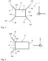
Fig. 1 shows a schematic view on a first side surface of a low gravity lander according to the invention.Fig. 2 shows a schematic view of the low gravity lander ofFig. 1 viewed from its right side.Fig. 3 shows a schematic view of the low gravity lander ofFig. 1 viewed from its top side seen inFig. 1 and illustrating the determination of the length of the number of rods with regard to an expected surface roughness.Fig. 4 shows a schematic view of a low gravity lander according to the invention where the number of rods is in a stowing position.Fig. 1 shows alow gravity lander 1, comprising a substantially rectangularmain body 10 and alanding device 20 having a number of leg-like rods main body 10 illustrated inFig. 1 is afirst side surface 11 corresponding to a front of thelow gravity lander 1. Thefirst side surface 11 has a substantially rectangular shape. However, it is to be understood that the rectangular shape of thefirst side surface 11 is by way of example only. Thelanding device 20 comprises fourrods respective end side surface 11 or an adjacent area of a side wall extending orthogonal to thefirst side surface 11. As can be seen fromFig. 2 which shows thelow gravity lander 1 ofFig. 1 from its right side, an inclination angle α between eachrod landing device 20, therods side surface 11. The extension of therods Figs. 1 and 2 .- Each of the
rods rods landing surface 40, thereby absorbing an impact momentum. Hence, the material of therods - The length L of the
rods Figs. 1 to 3 in which rods are depicted with length L and inclination angle α with regard to the first side surface 11) and an expected roughness of the landing surface such that no part of the landing surface is supposed to contact the main body of thelow gravity lander 1 before therods Fig. 3 which illustrates thelow gravity lander 1 in a landing position on alanding surface 40, thelanding surface 40 has one ormore elevations 41 which are directed to thefirst side surface 11. Thelanding surface 40 can be determined in front of a mission of a low gravity lander. - The smaller the inclination angle α is the bigger the distance between the
first side surface 11 and thelanding surface 40 can be achieved. However, due to the resulting geometry of the landing device, the behavior of therods landing surface 40 gets. Thus, the danger of a contact of themain body 10 and anelevation 41 of thelanding surface 40 rises. However, the stiffness of thelanding device 20 and itsrods - The length of the rods is further determined as a function of the stowage space such that, in a stowage position as illustrated in
Fig. 4 , the rods do not extend beyond thefirst side surface 11 of themain body 10. - The thickness and material of the
rods low gravity lander 1 and its impact velocity. The thicker therods Hollow rods - Where a soft terrain of the
landing surface 40 is expected, respective free ends 21E, 22E, 23E and 24E can be bent or fitted with a disc (not shown) to increase the area of contact. However, in the case of therods rods Fig. 4 shows thelow gravity lander 1 with thelanding device 20 in a stowing position of itsrods rods rods rods first side surface 11 of themain body 10 can be secured by a single hold downpoint 30. The hold down point may be a launch lock which is able to prevent premature deployment of the rods from its stowing position inFig. 4 to its deployment position inFigs. 1 to 3 . Premature deployment of therods low gravity lander 1 from a mother spacecraft. Thelaunch lock 30 may be opened immediately prior to the ejection of the low gravity lander. A time release device such as a bimetallic or shape memory alloy may be used which secures the rods for a predetermined time (on the order of minutes) upon a triggering event. Upon triggering the bimetallic or shape memory alloy may be preheated before ejection which then frees therods - The
rods respective end main body 10 with a hinge with only one degree of freedom. - If the
low gravity lander 1 needs to self-right itself after the impact of thelanding surface 40 it may jettison therods rods - The landing device described is vastly simpler, lighter and less costly than alternative landing systems. The landing device can be fitted even on miniaturized landers. It tolerates all surface properties and most topologies.
- As an advantage, spacecrafts deploying a low gravity lander as described are no longer required to approach dangerously close to the target bodies, such as a comet or a planet.
- Reference list
- 1
- low gravity lander
- 10
- main body
- 11
- first side surface
- 12
- second side surface (being arranged opposite to the first side surface)
- 20
- landing device
- 21
- rod of a first pair of rods
- 22
- rod of a second pair of rods
- 23
- rod of a second pair of rods
- 24
- rod of a first pair of rods
- 21E
- free end of
rod 21 - 22E
- free end of
rod 22 - 23E
- free end of
rod 23 - 24E
- free end of
rod 24 - 21A
- to
main body 10 attached end ofrod 21 - 22A
- to
main body 10 attached free end ofrod 22 - 23A
- to
main body 10 attached free end ofrod 23 - 24A
- to
main body 10 attached free end ofrod 24 - 30
- launch lock
- 40
- landing surface
- 41
- elevation
- L
- length of
rods - α
- Inclination angle
Claims (14)
- A landing device for a low gravity lander (1) having a main body (10), the landing device comprising a number of leg-like rods (21, 22, 23, 24) , the number of leg-like rods (21, 22, 23, 24) being attachable to a common first side surface (11) of the main body (10), wherein, in the deployment position of the rods (21, 22, 23, 24), each of the number of rods (21, 22, 23, 24) is inclined with regard to a plane of the first side surface (11) of the main body (10) such that the rods substantially extend in a direction of movement of the low gravity lander (1), and wherein the number of rods (21, 22, 23, 24) is made such that they bend or buckle under forces within a predetermined range by an impact due to a landing on a landing surface (40), thereby absorbing an impact momentum,characterised in that the number of leg-like rods is deployable from a stowage position to a deployment position during a landing process.
- The landing device according to claim 1, wherein the number of rods (21, 22, 23, 24) is greater than 3, and in particular equals 4.
- The landing device according to claim 1 or 2, wherein the length of the rods (21, 22, 23, 24) is determined as a function of the stowage space such that, in the stowage position, the rods (21, 22, 23, 24) do not extend beyond the first side surface (11) of the main body, wherein, in the stowage position, the number of rods (21, 22, 23, 24) are stowed above each other such that they substantially extend parallel to the plane of the first side surface (11).
- The landing device according to one of the preceding claims, wherein the inclination angle of the number of rods is in a range between 120° and 150°, in particular 135°.
- The landing device according to claim 4, wherein the number of rods (21, 22, 23, 24) extends, in the deployment position, beyond the lateral edges of the first side surface (11).
- The landing device according to one of the preceding claims, wherein the number of rods (21, 22, 23, 24) is hollow.
- The landing device according to one of the preceding claims, wherein the thickness and/or material of the number of rods (21, 22, 23, 24) is determined as a function of the expected impact momentum.
- The landing device according to one of the preceding claims, wherein a free end of at least some of the number of rods (21, 22, 23, 24) is bent.
- The landing device according to one of the preceding claims, wherein a free end of at least some of the number of rods (21, 22, 23, 24) is fitted with a disc.
- The landing device according to one of the preceding claims, wherein the number of rods (21, 22, 23, 24) is deployable by a swiveling mechanism.
- The landing device according to one of the preceding claims, wherein, in the stowing position, the number of rods (21, 22, 23, 24) is held/locked by a single hold down device.
- The landing device according to one of the preceding claims, wherein the landing device comprises an activatable launch lock to prevent premature deployment, the launch lock being a time release device which enables a deployment of the number of rods (21, 22, 23, 24) from their stowage position to their deployment position upon a triggering event.
- The landing device according to one of the preceding claims, wherein the main body (10) comprises a second side surface (12) being arranged opposite to the first side surface (11) of the main body (10), wherein a further number of leg-like rods is assigned to or attached to the second side surface (11).
- A low gravity lander (1) comprising a main body (10) and a landing device according to one of the preceding claims.
Priority Applications (2)
| Application Number | Priority Date | Filing Date | Title |
|---|---|---|---|
| EP15002096.4AEP3118124B1 (en) | 2015-07-15 | 2015-07-15 | Landing device for a low gravity lander |
| US15/209,316US10179663B2 (en) | 2015-07-15 | 2016-07-13 | Landing device for a low gravity lander |
Applications Claiming Priority (1)
| Application Number | Priority Date | Filing Date | Title |
|---|---|---|---|
| EP15002096.4AEP3118124B1 (en) | 2015-07-15 | 2015-07-15 | Landing device for a low gravity lander |
Publications (2)
| Publication Number | Publication Date |
|---|---|
| EP3118124A1 EP3118124A1 (en) | 2017-01-18 |
| EP3118124B1true EP3118124B1 (en) | 2021-05-12 |
Family
ID=53673718
Family Applications (1)
| Application Number | Title | Priority Date | Filing Date |
|---|---|---|---|
| EP15002096.4AActiveEP3118124B1 (en) | 2015-07-15 | 2015-07-15 | Landing device for a low gravity lander |
Country Status (2)
| Country | Link |
|---|---|
| US (1) | US10179663B2 (en) |
| EP (1) | EP3118124B1 (en) |
Families Citing this family (10)
| Publication number | Priority date | Publication date | Assignee | Title |
|---|---|---|---|---|
| DK3151582T3 (en)* | 2015-09-30 | 2020-10-12 | Apple Inc | HEADPHONE WITH CHARGING SYSTEM CASE |
| CN111114850B (en)* | 2018-10-30 | 2022-09-13 | 哈尔滨工业大学 | Three-leg support asteroid surface anchoring device based on impact type ultrasonic drill |
| CN112046775A (en)* | 2019-06-06 | 2020-12-08 | 宋延军 | A kind of vertical soft landing auxiliary system and landing method of jet aircraft |
| JP7349838B2 (en)* | 2019-07-18 | 2023-09-25 | 三菱電機株式会社 | Exploration vehicle, fall prevention method, and fall prevention control device |
| CN111891409B (en)* | 2020-06-28 | 2022-04-12 | 北京控制工程研究所 | A rigid-flex dual-mode reusable landing buffer device |
| CN113776394B (en)* | 2021-08-20 | 2023-05-09 | 北京精密机电控制设备研究所 | Arrow-spliced type adjustable tenon lock pressing and unlocking device and method |
| CN115743609B (en)* | 2022-10-18 | 2024-10-18 | 中国石油大学(北京) | Star table fixing components based on shape memory alloy |
| CN115783306B (en)* | 2022-12-28 | 2024-05-28 | 北华大学 | Single motor rope driven slide rail direct swing lifting transfer mechanism and transfer method |
| JP7366328B1 (en)* | 2023-03-06 | 2023-10-20 | 三菱電機株式会社 | Fall risk detection method, fall risk detection device, flying object and program |
| CN118723124B (en)* | 2024-06-25 | 2025-09-30 | 哈尔滨工业大学 | Deployable flexible landing device for asteroid exploration satellite and use method thereof |
Family Cites Families (6)
| Publication number | Priority date | Publication date | Assignee | Title |
|---|---|---|---|---|
| US5265829A (en)* | 1993-02-03 | 1993-11-30 | The United States Of America As Represented By The Administrator Of The National Aeronautics And Space Administration | Tetrahedral lander |
| JP3870257B2 (en)* | 2002-05-02 | 2007-01-17 | 独立行政法人 宇宙航空研究開発機構 | Robot with offset rotary joint |
| US7748486B2 (en)* | 2005-06-09 | 2010-07-06 | Honeywell International, Inc. | Landing gear for a hovercraft |
| US7628353B2 (en)* | 2006-11-14 | 2009-12-08 | Raytheon Company | Delayed tail fin deployment mechanism and method |
| FR2946323B1 (en)* | 2009-06-04 | 2012-12-21 | Astrium Sas | SYSTEM FOR LANDING A BODY AND SPATIAL PROBE EQUIPPED WITH SUCH A SYSTEM |
| WO2011096942A1 (en)* | 2010-02-08 | 2011-08-11 | Raymond George Carreker | Variable surface landing platform (varslap) |
- 2015
- 2015-07-15EPEP15002096.4Apatent/EP3118124B1/enactiveActive
- 2016
- 2016-07-13USUS15/209,316patent/US10179663B2/enactiveActive
Non-Patent Citations (1)
| Title |
|---|
| None* |
Also Published As
| Publication number | Publication date |
|---|---|
| US10179663B2 (en) | 2019-01-15 |
| EP3118124A1 (en) | 2017-01-18 |
| US20170015442A1 (en) | 2017-01-19 |
Similar Documents
| Publication | Publication Date | Title |
|---|---|---|
| EP3118124B1 (en) | Landing device for a low gravity lander | |
| JP6813997B2 (en) | Small aircraft with airbag device | |
| US5814753A (en) | Device for the nonlethal combating of aircraft | |
| US8469314B2 (en) | Technique for de-orbiting small debris from the near-earth space environment | |
| Ragab et al. | Launch vehicle recovery and reuse | |
| US20160046372A1 (en) | Rocket Morphing Aerial Vehicle | |
| US8292232B1 (en) | Deployable decelerator based microsatellite recovery | |
| US6726153B1 (en) | Photon momentum transfer plane for asteroid, meteoroid, and comet orbit shaping | |
| EP1917495A2 (en) | Ejectable aerodynamic stability and control | |
| US20160272333A1 (en) | Autonomous airbag system for unmanned aerial vehicles | |
| US5456427A (en) | Air-launchable gliding sonobuoy | |
| US9296470B1 (en) | Deployable apparatus for use with air vehicles | |
| CN105940237B (en) | Collision buffer | |
| KR101356554B1 (en) | Deploying and folding mechanism of wing for a portable guided missile | |
| US11623730B2 (en) | Canopy separation systems and methods for an aircraft | |
| KR20120056123A (en) | Protective cover of missile, missile having the same and impact relief method of missile | |
| US11155354B2 (en) | Airbag systems | |
| EP3805099B1 (en) | Emergency landing device | |
| Schmidt et al. | Kentucky Re-Entry Universal Payload System (KRUPS): Overview of flight test via high-altitude balloon | |
| Otsuki et al. | Development of hybrid landing gear for OMOTENASHI surface probe | |
| Marraffa et al. | IRDT-Inflatable Re-entry and Descent Technology | |
| Lingard et al. | Supersonic parachute testing using a MAXUS sounding rocket piggy-back payload | |
| US20040124313A1 (en) | De-orbit instrument package | |
| Stamminger et al. | Sounding rockets as a real flight platform for Aerothermodynamic CFD validation of hypersonic experiments | |
| Annavarapu | Conceptual Design of Mars Lander with Novel Impact Intriguing System |
Legal Events
| Date | Code | Title | Description |
|---|---|---|---|
| PUAI | Public reference made under article 153(3) epc to a published international application that has entered the european phase | Free format text:ORIGINAL CODE: 0009012 | |
| STAA | Information on the status of an ep patent application or granted ep patent | Free format text:STATUS: THE APPLICATION HAS BEEN PUBLISHED | |
| AK | Designated contracting states | Kind code of ref document:A1 Designated state(s):AL AT BE BG CH CY CZ DE DK EE ES FI FR GB GR HR HU IE IS IT LI LT LU LV MC MK MT NL NO PL PT RO RS SE SI SK SM TR | |
| AX | Request for extension of the european patent | Extension state:BA ME | |
| STAA | Information on the status of an ep patent application or granted ep patent | Free format text:STATUS: REQUEST FOR EXAMINATION WAS MADE | |
| 17P | Request for examination filed | Effective date:20170713 | |
| RBV | Designated contracting states (corrected) | Designated state(s):AL AT BE BG CH CY CZ DE DK EE ES FI FR GB GR HR HU IE IS IT LI LT LU LV MC MK MT NL NO PL PT RO RS SE SI SK SM TR | |
| RAP1 | Party data changed (applicant data changed or rights of an application transferred) | Owner name:AIRBUS DEFENCE AND SPACE GMBH | |
| STAA | Information on the status of an ep patent application or granted ep patent | Free format text:STATUS: EXAMINATION IS IN PROGRESS | |
| 17Q | First examination report despatched | Effective date:20190514 | |
| RIC1 | Information provided on ipc code assigned before grant | Ipc:B64G 1/10 20060101ALN20201028BHEP Ipc:B64G 1/62 20060101AFI20201028BHEP | |
| GRAP | Despatch of communication of intention to grant a patent | Free format text:ORIGINAL CODE: EPIDOSNIGR1 | |
| STAA | Information on the status of an ep patent application or granted ep patent | Free format text:STATUS: GRANT OF PATENT IS INTENDED | |
| INTG | Intention to grant announced | Effective date:20201207 | |
| GRAS | Grant fee paid | Free format text:ORIGINAL CODE: EPIDOSNIGR3 | |
| GRAA | (expected) grant | Free format text:ORIGINAL CODE: 0009210 | |
| STAA | Information on the status of an ep patent application or granted ep patent | Free format text:STATUS: THE PATENT HAS BEEN GRANTED | |
| AK | Designated contracting states | Kind code of ref document:B1 Designated state(s):AL AT BE BG CH CY CZ DE DK EE ES FI FR GB GR HR HU IE IS IT LI LT LU LV MC MK MT NL NO PL PT RO RS SE SI SK SM TR | |
| REG | Reference to a national code | Ref country code:GB Ref legal event code:FG4D | |
| REG | Reference to a national code | Ref country code:CH Ref legal event code:EP | |
| REG | Reference to a national code | Ref country code:DE Ref legal event code:R096 Ref document number:602015069173 Country of ref document:DE | |
| REG | Reference to a national code | Ref country code:IE Ref legal event code:FG4D | |
| REG | Reference to a national code | Ref country code:AT Ref legal event code:REF Ref document number:1392048 Country of ref document:AT Kind code of ref document:T Effective date:20210615 | |
| REG | Reference to a national code | Ref country code:LT Ref legal event code:MG9D | |
| REG | Reference to a national code | Ref country code:AT Ref legal event code:MK05 Ref document number:1392048 Country of ref document:AT Kind code of ref document:T Effective date:20210512 | |
| REG | Reference to a national code | Ref country code:NL Ref legal event code:MP Effective date:20210512 | |
| PG25 | Lapsed in a contracting state [announced via postgrant information from national office to epo] | Ref country code:HR Free format text:LAPSE BECAUSE OF FAILURE TO SUBMIT A TRANSLATION OF THE DESCRIPTION OR TO PAY THE FEE WITHIN THE PRESCRIBED TIME-LIMIT Effective date:20210512 Ref country code:FI Free format text:LAPSE BECAUSE OF FAILURE TO SUBMIT A TRANSLATION OF THE DESCRIPTION OR TO PAY THE FEE WITHIN THE PRESCRIBED TIME-LIMIT Effective date:20210512 Ref country code:LT Free format text:LAPSE BECAUSE OF FAILURE TO SUBMIT A TRANSLATION OF THE DESCRIPTION OR TO PAY THE FEE WITHIN THE PRESCRIBED TIME-LIMIT Effective date:20210512 Ref country code:AT Free format text:LAPSE BECAUSE OF FAILURE TO SUBMIT A TRANSLATION OF THE DESCRIPTION OR TO PAY THE FEE WITHIN THE PRESCRIBED TIME-LIMIT Effective date:20210512 Ref country code:BG Free format text:LAPSE BECAUSE OF FAILURE TO SUBMIT A TRANSLATION OF THE DESCRIPTION OR TO PAY THE FEE WITHIN THE PRESCRIBED TIME-LIMIT Effective date:20210812 | |
| PG25 | Lapsed in a contracting state [announced via postgrant information from national office to epo] | Ref country code:LV Free format text:LAPSE BECAUSE OF FAILURE TO SUBMIT A TRANSLATION OF THE DESCRIPTION OR TO PAY THE FEE WITHIN THE PRESCRIBED TIME-LIMIT Effective date:20210512 Ref country code:GR Free format text:LAPSE BECAUSE OF FAILURE TO SUBMIT A TRANSLATION OF THE DESCRIPTION OR TO PAY THE FEE WITHIN THE PRESCRIBED TIME-LIMIT Effective date:20210813 Ref country code:IS Free format text:LAPSE BECAUSE OF FAILURE TO SUBMIT A TRANSLATION OF THE DESCRIPTION OR TO PAY THE FEE WITHIN THE PRESCRIBED TIME-LIMIT Effective date:20210912 Ref country code:ES Free format text:LAPSE BECAUSE OF FAILURE TO SUBMIT A TRANSLATION OF THE DESCRIPTION OR TO PAY THE FEE WITHIN THE PRESCRIBED TIME-LIMIT Effective date:20210512 Ref country code:NO Free format text:LAPSE BECAUSE OF FAILURE TO SUBMIT A TRANSLATION OF THE DESCRIPTION OR TO PAY THE FEE WITHIN THE PRESCRIBED TIME-LIMIT Effective date:20210812 Ref country code:PL Free format text:LAPSE BECAUSE OF FAILURE TO SUBMIT A TRANSLATION OF THE DESCRIPTION OR TO PAY THE FEE WITHIN THE PRESCRIBED TIME-LIMIT Effective date:20210512 Ref country code:PT Free format text:LAPSE BECAUSE OF FAILURE TO SUBMIT A TRANSLATION OF THE DESCRIPTION OR TO PAY THE FEE WITHIN THE PRESCRIBED TIME-LIMIT Effective date:20210913 Ref country code:SE Free format text:LAPSE BECAUSE OF FAILURE TO SUBMIT A TRANSLATION OF THE DESCRIPTION OR TO PAY THE FEE WITHIN THE PRESCRIBED TIME-LIMIT Effective date:20210512 Ref country code:RS Free format text:LAPSE BECAUSE OF FAILURE TO SUBMIT A TRANSLATION OF THE DESCRIPTION OR TO PAY THE FEE WITHIN THE PRESCRIBED TIME-LIMIT Effective date:20210512 | |
| PG25 | Lapsed in a contracting state [announced via postgrant information from national office to epo] | Ref country code:NL Free format text:LAPSE BECAUSE OF FAILURE TO SUBMIT A TRANSLATION OF THE DESCRIPTION OR TO PAY THE FEE WITHIN THE PRESCRIBED TIME-LIMIT Effective date:20210512 | |
| PG25 | Lapsed in a contracting state [announced via postgrant information from national office to epo] | Ref country code:DK Free format text:LAPSE BECAUSE OF FAILURE TO SUBMIT A TRANSLATION OF THE DESCRIPTION OR TO PAY THE FEE WITHIN THE PRESCRIBED TIME-LIMIT Effective date:20210512 Ref country code:EE Free format text:LAPSE BECAUSE OF FAILURE TO SUBMIT A TRANSLATION OF THE DESCRIPTION OR TO PAY THE FEE WITHIN THE PRESCRIBED TIME-LIMIT Effective date:20210512 Ref country code:CZ Free format text:LAPSE BECAUSE OF FAILURE TO SUBMIT A TRANSLATION OF THE DESCRIPTION OR TO PAY THE FEE WITHIN THE PRESCRIBED TIME-LIMIT Effective date:20210512 Ref country code:SM Free format text:LAPSE BECAUSE OF FAILURE TO SUBMIT A TRANSLATION OF THE DESCRIPTION OR TO PAY THE FEE WITHIN THE PRESCRIBED TIME-LIMIT Effective date:20210512 Ref country code:SK Free format text:LAPSE BECAUSE OF FAILURE TO SUBMIT A TRANSLATION OF THE DESCRIPTION OR TO PAY THE FEE WITHIN THE PRESCRIBED TIME-LIMIT Effective date:20210512 Ref country code:RO Free format text:LAPSE BECAUSE OF FAILURE TO SUBMIT A TRANSLATION OF THE DESCRIPTION OR TO PAY THE FEE WITHIN THE PRESCRIBED TIME-LIMIT Effective date:20210512 | |
| REG | Reference to a national code | Ref country code:DE Ref legal event code:R097 Ref document number:602015069173 Country of ref document:DE | |
| REG | Reference to a national code | Ref country code:CH Ref legal event code:PL | |
| PLBE | No opposition filed within time limit | Free format text:ORIGINAL CODE: 0009261 | |
| STAA | Information on the status of an ep patent application or granted ep patent | Free format text:STATUS: NO OPPOSITION FILED WITHIN TIME LIMIT | |
| PG25 | Lapsed in a contracting state [announced via postgrant information from national office to epo] | Ref country code:MC Free format text:LAPSE BECAUSE OF FAILURE TO SUBMIT A TRANSLATION OF THE DESCRIPTION OR TO PAY THE FEE WITHIN THE PRESCRIBED TIME-LIMIT Effective date:20210512 | |
| REG | Reference to a national code | Ref country code:BE Ref legal event code:MM Effective date:20210731 | |
| 26N | No opposition filed | Effective date:20220215 | |
| PG25 | Lapsed in a contracting state [announced via postgrant information from national office to epo] | Ref country code:LI Free format text:LAPSE BECAUSE OF NON-PAYMENT OF DUE FEES Effective date:20210731 Ref country code:CH Free format text:LAPSE BECAUSE OF NON-PAYMENT OF DUE FEES Effective date:20210731 | |
| PG25 | Lapsed in a contracting state [announced via postgrant information from national office to epo] | Ref country code:IS Free format text:LAPSE BECAUSE OF FAILURE TO SUBMIT A TRANSLATION OF THE DESCRIPTION OR TO PAY THE FEE WITHIN THE PRESCRIBED TIME-LIMIT Effective date:20210912 Ref country code:LU Free format text:LAPSE BECAUSE OF NON-PAYMENT OF DUE FEES Effective date:20210715 Ref country code:AL Free format text:LAPSE BECAUSE OF FAILURE TO SUBMIT A TRANSLATION OF THE DESCRIPTION OR TO PAY THE FEE WITHIN THE PRESCRIBED TIME-LIMIT Effective date:20210512 | |
| PG25 | Lapsed in a contracting state [announced via postgrant information from national office to epo] | Ref country code:IT Free format text:LAPSE BECAUSE OF FAILURE TO SUBMIT A TRANSLATION OF THE DESCRIPTION OR TO PAY THE FEE WITHIN THE PRESCRIBED TIME-LIMIT Effective date:20210512 Ref country code:IE Free format text:LAPSE BECAUSE OF NON-PAYMENT OF DUE FEES Effective date:20210715 Ref country code:BE Free format text:LAPSE BECAUSE OF NON-PAYMENT OF DUE FEES Effective date:20210731 | |
| PG25 | Lapsed in a contracting state [announced via postgrant information from national office to epo] | Ref country code:HU Free format text:LAPSE BECAUSE OF FAILURE TO SUBMIT A TRANSLATION OF THE DESCRIPTION OR TO PAY THE FEE WITHIN THE PRESCRIBED TIME-LIMIT; INVALID AB INITIO Effective date:20150715 | |
| PG25 | Lapsed in a contracting state [announced via postgrant information from national office to epo] | Ref country code:CY Free format text:LAPSE BECAUSE OF FAILURE TO SUBMIT A TRANSLATION OF THE DESCRIPTION OR TO PAY THE FEE WITHIN THE PRESCRIBED TIME-LIMIT Effective date:20210512 | |
| PG25 | Lapsed in a contracting state [announced via postgrant information from national office to epo] | Ref country code:MK Free format text:LAPSE BECAUSE OF FAILURE TO SUBMIT A TRANSLATION OF THE DESCRIPTION OR TO PAY THE FEE WITHIN THE PRESCRIBED TIME-LIMIT Effective date:20210512 | |
| PG25 | Lapsed in a contracting state [announced via postgrant information from national office to epo] | Ref country code:TR Free format text:LAPSE BECAUSE OF FAILURE TO SUBMIT A TRANSLATION OF THE DESCRIPTION OR TO PAY THE FEE WITHIN THE PRESCRIBED TIME-LIMIT Effective date:20210512 | |
| PG25 | Lapsed in a contracting state [announced via postgrant information from national office to epo] | Ref country code:MT Free format text:LAPSE BECAUSE OF FAILURE TO SUBMIT A TRANSLATION OF THE DESCRIPTION OR TO PAY THE FEE WITHIN THE PRESCRIBED TIME-LIMIT Effective date:20210512 | |
| PGFP | Annual fee paid to national office [announced via postgrant information from national office to epo] | Ref country code:DE Payment date:20240719 Year of fee payment:10 | |
| PGFP | Annual fee paid to national office [announced via postgrant information from national office to epo] | Ref country code:GB Payment date:20240723 Year of fee payment:10 | |
| PGFP | Annual fee paid to national office [announced via postgrant information from national office to epo] | Ref country code:FR Payment date:20240730 Year of fee payment:10 |