EP3117788A1 - Uni-planar bone fixation assembly - Google Patents
Uni-planar bone fixation assemblyDownload PDFInfo
- Publication number
- EP3117788A1 EP3117788A1EP16162864.9AEP16162864AEP3117788A1EP 3117788 A1EP3117788 A1EP 3117788A1EP 16162864 AEP16162864 AEP 16162864AEP 3117788 A1EP3117788 A1EP 3117788A1
- Authority
- EP
- European Patent Office
- Prior art keywords
- anchor
- bone
- collet
- bone fixation
- subassembly
- Prior art date
- Legal status (The legal status is an assumption and is not a legal conclusion. Google has not performed a legal analysis and makes no representation as to the accuracy of the status listed.)
- Granted
Links
- 210000000988bone and boneAnatomy0.000titleclaimsabstractdescription410
- 125000006850spacer groupChemical group0.000description29
- 238000000034methodMethods0.000description10
- 238000003780insertionMethods0.000description8
- 230000037431insertionEffects0.000description8
- 241001274197Scatophagus argusSpecies0.000description6
- 230000000712assemblyEffects0.000description4
- 238000000429assemblyMethods0.000description4
- 239000012530fluidSubstances0.000description2
- 239000000463materialSubstances0.000description2
- 230000000717retained effectEffects0.000description2
- 239000007787solidSubstances0.000description2
- 229910001257Nb alloyInorganic materials0.000description1
- 238000013459approachMethods0.000description1
- 239000011324beadSubstances0.000description1
- 230000008901benefitEffects0.000description1
- 238000005422blastingMethods0.000description1
- 230000008859changeEffects0.000description1
- 230000006835compressionEffects0.000description1
- 238000007906compressionMethods0.000description1
- 238000000605extractionMethods0.000description1
- 239000007943implantSubstances0.000description1
- 238000002513implantationMethods0.000description1
- 230000008676importEffects0.000description1
- 238000002347injectionMethods0.000description1
- 239000007924injectionSubstances0.000description1
- 230000014759maintenance of locationEffects0.000description1
- 238000004519manufacturing processMethods0.000description1
- 230000013011matingEffects0.000description1
- 230000008569processEffects0.000description1
- 230000004044responseEffects0.000description1
- 206010039722scoliosisDiseases0.000description1
- 239000010935stainless steelSubstances0.000description1
- 229910001220stainless steelInorganic materials0.000description1
- 230000003746surface roughnessEffects0.000description1
- 210000000115thoracic cavityAnatomy0.000description1
- -1titanium-aluminum-niobiumChemical compound0.000description1
Images


Classifications
- A—HUMAN NECESSITIES
- A61—MEDICAL OR VETERINARY SCIENCE; HYGIENE
- A61B—DIAGNOSIS; SURGERY; IDENTIFICATION
- A61B17/00—Surgical instruments, devices or methods
- A61B17/56—Surgical instruments or methods for treatment of bones or joints; Devices specially adapted therefor
- A61B17/58—Surgical instruments or methods for treatment of bones or joints; Devices specially adapted therefor for osteosynthesis, e.g. bone plates, screws or setting implements
- A61B17/68—Internal fixation devices, including fasteners and spinal fixators, even if a part thereof projects from the skin
- A61B17/70—Spinal positioners or stabilisers, e.g. stabilisers comprising fluid filler in an implant
- A61B17/7001—Screws or hooks combined with longitudinal elements which do not contact vertebrae
- A61B17/7035—Screws or hooks, wherein a rod-clamping part and a bone-anchoring part can pivot relative to each other
- A61B17/7038—Screws or hooks, wherein a rod-clamping part and a bone-anchoring part can pivot relative to each other to a different extent in different directions, e.g. within one plane only
- A—HUMAN NECESSITIES
- A61—MEDICAL OR VETERINARY SCIENCE; HYGIENE
- A61B—DIAGNOSIS; SURGERY; IDENTIFICATION
- A61B17/00—Surgical instruments, devices or methods
- A61B17/56—Surgical instruments or methods for treatment of bones or joints; Devices specially adapted therefor
- A61B17/58—Surgical instruments or methods for treatment of bones or joints; Devices specially adapted therefor for osteosynthesis, e.g. bone plates, screws or setting implements
- A61B17/68—Internal fixation devices, including fasteners and spinal fixators, even if a part thereof projects from the skin
- A61B17/70—Spinal positioners or stabilisers, e.g. stabilisers comprising fluid filler in an implant
- A61B17/7001—Screws or hooks combined with longitudinal elements which do not contact vertebrae
- A61B17/7032—Screws or hooks with U-shaped head or back through which longitudinal rods pass
- A—HUMAN NECESSITIES
- A61—MEDICAL OR VETERINARY SCIENCE; HYGIENE
- A61B—DIAGNOSIS; SURGERY; IDENTIFICATION
- A61B17/00—Surgical instruments, devices or methods
- A61B17/56—Surgical instruments or methods for treatment of bones or joints; Devices specially adapted therefor
- A61B17/58—Surgical instruments or methods for treatment of bones or joints; Devices specially adapted therefor for osteosynthesis, e.g. bone plates, screws or setting implements
- A61B17/68—Internal fixation devices, including fasteners and spinal fixators, even if a part thereof projects from the skin
- A61B17/70—Spinal positioners or stabilisers, e.g. stabilisers comprising fluid filler in an implant
- A61B17/7001—Screws or hooks combined with longitudinal elements which do not contact vertebrae
- A61B17/7035—Screws or hooks, wherein a rod-clamping part and a bone-anchoring part can pivot relative to each other
- A61B17/7037—Screws or hooks, wherein a rod-clamping part and a bone-anchoring part can pivot relative to each other wherein pivoting is blocked when the rod is clamped
- A—HUMAN NECESSITIES
- A61—MEDICAL OR VETERINARY SCIENCE; HYGIENE
- A61B—DIAGNOSIS; SURGERY; IDENTIFICATION
- A61B17/00—Surgical instruments, devices or methods
- A61B17/56—Surgical instruments or methods for treatment of bones or joints; Devices specially adapted therefor
- A61B17/58—Surgical instruments or methods for treatment of bones or joints; Devices specially adapted therefor for osteosynthesis, e.g. bone plates, screws or setting implements
- A61B17/68—Internal fixation devices, including fasteners and spinal fixators, even if a part thereof projects from the skin
- A61B17/70—Spinal positioners or stabilisers, e.g. stabilisers comprising fluid filler in an implant
- A61B17/7049—Connectors, not bearing on the vertebrae, for linking longitudinal elements together
- A—HUMAN NECESSITIES
- A61—MEDICAL OR VETERINARY SCIENCE; HYGIENE
- A61B—DIAGNOSIS; SURGERY; IDENTIFICATION
- A61B17/00—Surgical instruments, devices or methods
- A61B17/56—Surgical instruments or methods for treatment of bones or joints; Devices specially adapted therefor
- A61B17/58—Surgical instruments or methods for treatment of bones or joints; Devices specially adapted therefor for osteosynthesis, e.g. bone plates, screws or setting implements
- A61B17/68—Internal fixation devices, including fasteners and spinal fixators, even if a part thereof projects from the skin
- A61B17/84—Fasteners therefor or fasteners being internal fixation devices
- A61B17/86—Pins or screws or threaded wires; nuts therefor
- A61B17/8685—Pins or screws or threaded wires; nuts therefor comprising multiple separate parts
Definitions
- Pedicle screw assembliesinclude a plurality of pedicle screws joined by a rod that extends through rod slots formed in the pedicle screws.
- Uni-planar pedicle screwsprovide one degree of freedom. That is, the bone anchor retained within the anchor seat and, in some systems, the collet, is free to move with respect to the anchor seat in only one plane, e.g., the sagittal plane. Motion of the bone anchor is limited to this sagittal plane in conventional pedicle screws by a pinning or staking process during manufacture of the assemblies to create a pivot in the sagittal plane.
- the height of the bone screwis limited by the orientation of the rod slot.
- the anchor seatmust be turned, which results in either advancing or withdrawing the screw toward and away from the bone surface.
- a bone fixation subassemblyis configured to receive a fixation rod and a locking cap.
- the bone fixation subassemblyincludes an anchor seat and a collet.
- the anchor seatincludes an anchor seat body extending along a central axis and defining an upper end and a lower end.
- the upper endincludes a pair of opposing fixation rod-receiving gaps therebetween that are spaced along a longitudinal axis, and a bore disposed between the rod-receiving gaps.
- the colletincludes a collet body disposed in the anchor seat. The collet body is configured to attach to a bone anchor that extends along an axis of rotation.
- a bone anchor attached to the colletis permitted to rotate about the axis of rotation relative to the anchor seat, and the bone anchor is further permitted to pivot relative to the anchor seat along a desired plane.
- the bone anchoris prevented from pivoting in another plane that includes the central axis and is angularly offset with respect to the desired plane.
- a bone fixation assembly 20includes one or more bone fixation elements 22, and four bone fixation elements 22A-D as illustrated in Fig. 1A .
- each bone fixation element 22extends vertically along an axial direction A, and generally horizontally along a radial direction R extends perpendicular to the axial direction A.
- the radial direction Rincludes a longitudinal direction L and a lateral direction LA that extends perpendicular to the longitudinal direction L.
- the directional termsare used herein with reference to the orientation of the bone fixation assembly 20 and its components as illustrated, and that the actual orientation of the bone fixation assembly 20 and its components may change during use.
- the axial directionis illustrated as extending along a vertical direction
- the radial directionis illustrated as extending along a horizontal direction, however the directions that encompass the various directions may differ during use, depending, for instance, on the desired orientation of the bone fixation assembly 20 during use.
- the directional termsare used herein merely for the purposes of clarity and convenience only, in a non-limiting manner.
- the bone anchor 30is configured as a bone screw, or pedicle screw, that includes an externally threaded shaft 31 coupled at its upper end to an enlarged curved head 33.
- the shaft 31extends axially along a central axis B of rotation, and can define any suitable diameter, length, and thread design so as to engage the underlying bone, such as a vertebra 27.
- the shaft 31can be unthreaded so as to define a pin or a nail if desired.
- the bone anchor 30is not limited to any particular type of shaft 31.
- the bone anchor 30may also be cannulated and fenestrated such that openings extend radially outward from a central hollow channel in a cannulated shaft to urge fluid out of the bone anchor 30 during injection or draw fluid into the central hollow channel from the radial sides of the anchor during extraction of material adjacent the anchor if desired.
- the head 33can define a semi-spherical curvature, or can alternatively define any suitable curvature as desired to facilitate rotation with respect to the collet 28 as is described in more detail below.
- the head 33defines a pivot location that extends along a lateral pivot axis of rotation LAp that extends through the head in a direction parallel to the lateral axis LA.
- the head 33further defines a pivot location that extends along a longitudinal axis of rotation L P that extends through the head in a direction parallel to the longitudinal axis L.
- the head 33also includes a drive surface 39 configured to receive a corresponding tip of a drive tool, such as a screw driver configured to rotate the bone anchor 30 into engagement with the vertebrae 27 or other underlying bone surface.
- the drive surface 39can define a hexagon, a star drive pattern, a Phillips head pattern, a slot for a screw driver, threads configured to receive corresponding threads of a threaded drive post, or any suitable drive tool engaging structure as desired.
- a gap Gextends circumferentially between adjacent circumferentially outer ends of the arms 42.
- the opposing gaps Gare in alignment with the axial bore 54.
- the arms 42can be disposed radially opposite each other such that the gaps G, in combination with the aligned portion of the axial bore 54, define a rod-receiving channel 36 that is sized and configured to receive the fixation rod 24 such that the fixation rod 24 extends through the bone fixation element 22.
- the gaps Gare aligned in the longitudinal direction.
- the fixation rod 24can thus extend through the opposing gaps G and the axial bore 54.
- the arms 42define radially inner and outer surfaces 60 and 62, respectively.
- the inner surfaces 60define threads 62, and are configured to threadedly receive the locking cap 34, as will now be described.
- the saddle 66can be coupled to the set screw 64 in any desired manner, including adhesion, mechanical fastening, and the like.
- the saddle 66includes a stem 78 extending centrally upward from the saddle body 72.
- the stem 78is configured to be received in a central bore 32 extending vertically into the lower end of the set screw body 65, and can be fastened within the central bore with a rivet 80 or other like fastener.
- the saddle 66is rotatable relative to the set screw 64, such that the saddle 66 can self-align with the fixation rod 24 as the set screw 64 is being rotated with respect to the anchor seat 26, for instance when the locking cap 34 is being tightened against the fixation rod 24.
- the support walls 56each define opposing inner and outer surfaces 86 and 88, respectively.
- the support walls 56flare inward toward axis A in a downward direction from the arms 42, and terminate at respective lower ends 90.
- the inner surfaces 86 of each support wall 56 at the lower end 90define a distance D therebetween that is less than the distance between opposing radially opposing inner surfaces 60 of the arms 42, and greater than the diameter of the head 33 of the bone anchor 30.
- the inner surfaces 86flare radially inward toward the central axis A, and toward each other, along a downward direction, and are each connected to bottommost, and innermost, surfaces that define respective longitudinal guide walls 92.
- each guide wall 92defines respective inner guide surfaces 93 that extend in a desired plane through which the bone anchor 30 is permitted to pivot relative to the anchor seat 26.
- the desired planeis the sagittal plane SP.
- the anchor seat 26can be constructed such that the guide walls 92 extend in any desired alternative plane, such as a plane defined by the medial-lateral and anterior-posterior directions.
- the guide walls 92can be spaced apart a distance greater than the diameter of the neck 35, but disposed within close proximity of the bone anchor 30, so as to limit pivotal movement of the bone anchor 30 relative to the anchor seat 34 in the first direction D in a plane that is perpendicular to the desired (e.g., sagittal plane), for instance about the longitudinal pivot axis L P .
- the bone anchor 30can pivot about the longitudinal pivot axis L P through a range of angles defined by the central anchor axis B and the central anchor seat axis A that is less than 10°, for instance less than 5°, such as 0°.
- the distance between the opposing guide walls 92is less than the diameter of the head 33 of the bone anchor 30, while the inner surfaces 86 define a distance therebetween that is slightly greater than the diameter of the anchor head 33.
- the bone anchorcan pivot more in the second direction E than in the first direction D.
- the bone anchor 30can pivot such that the central axis B of the bone anchor can be angularly offset with respect to the central axis A of the anchor seat 26 through a range of angles +/- between 0° and 90° with respect to the vertical, such as between 5° and 45°, including between 15° and 35°, for instance 25° in the sagittal plane before the neck 35 abuts the lower ends 82.
- the neck 35 of the anchor 30can ride along the guide wall 92 as it pivots in the sagittal plane SP.
- the collet 28includes a collet body 45 that defines a first or upper end 47 sized and configured to contact or support at least a portion of the fixation rod 24 when the rod is received within the rod-receiving channel 36, and a second or lower end 49 sized and configured to contact or otherwise engage, directly or indirectly, a portion of the bone anchor head 33.
- the collet body 45is annular, and thus defines an axial bore 53 extending between and through the upper and lower ends 47 and 49. The axial bore 53 is aligned with the axial bore 54 when the collet 28 is installed in the anchor seat 26.
- the upper end 47defines radially opposing upwardly facing seat portions 51 having a curvature or semi-spherical shape corresponding to the outer surface of the fixation rod 24, and is therefore configured to receive or otherwise support at least a portion (e.g., a lower portion) of the rod 24.
- the lower end 49defines an inner surface 55 defining a curvature or semi-spherical shape corresponding to the outer surface of the anchor head 33, and is therefore configured to receive or otherwise engage at least a portion of the head 33, so that the head can rotate with respect to the collet 28 and the anchor seat 26, and can further pivot with respect to the collet 28 as permitted by the anchor seat 26.
- the collet 28further includes a pair of flanges 57 extending up from the upper end 47 of the collet body 45 at a location radially between the seat portions 51.
- a locking lip 59extends radially out from each flange 57.
- the anchor seat 26defines a pair of opposing recesses 61 formed radially in the opposing inner surfaces 86 of the support walls 56 at a location below the threaded inner surfaces 60 of the arms 42.
- the collet 28can be inserted down into the anchor seat 26, thereby causing the flanges 57 to flex inwardly past the threaded inner surfaces 60, until the lips 59 clear the upper ends 63 of the recesses 61, at which point the flanges 57 snap back out so that the lips 59 are disposed in the recesses 61. Interference between the lips 59 and the upper ends 63 prevent the collet 28 from backing out through the upper end of the anchor scat 26.
- the recesses 61further define a circumferential length substantially equal to that of the flanges 57 and locking lips 59, such that the collet 28 is rotationally fixed with respect to the anchor seat 26 in a position whereby the upper surface 47 is aligned with the fixation rod 24 when the fixation rod 24 is inserted into the anchor seat 26.
- the lower end 49 of the collet 28defines an outer diameter that is greater than the inner distance between the guide walls 92. Accordingly, the collet 28 is unable to pass axially down through the lower end of the anchor body 26.
- the lower end 49includes one or more slots 67 (illustrated as a plurality of slots) extending radially therethrough so as to define opposing pluralities of fingers 69A and 69B.
- the fingers 69A and 69Bwhen the collet 28 and anchor 30 are installed in the anchor seat 24, the fingers 69A and 69B radially expand to conform with the outer surface of the anchor head 33 and the inner surfaces of the support walls 56 and spacer walls 58, respectively, as illustrated in Figs. 7A-B .
- the inner diameters defined by the opposing fingers 69A and 69Bare less than the outer diameter of the anchor head 33 to prevent the anchor 30 from being removed from the anchor seat 26 in an axially downward direction.
- the lower ends of the fingers 69Aterminate at a location above the guide walls 92, and the lower ends of the fingers 69B terminate at a location above the lower ends 82. Accordingly, the fingers 69A and 69B do not interfere with the engagement between the anchor neck 35 and the guide walls 92 and lower ends 82, and thus do not interfere with the permissible movement of the bone anchors 30 relative to the anchor seat 26.
- one or both of the pluralities of fingers 69A-Bcould extend below the anchor seat 26, and thus abut the anchor 30 in the manner described above with respect to the guide 92 and stop surface 82 so as to direct movement of the bone anchor 30 in a desired direction (e.g., pivot in the sagittal plane).
- a method for assembling a bone fixation subassembly 75includes at step 1, inserting the bone anchor 30 vertically down through the axial bore 54, such that the shaft 31 extends through the lower opening 52 of the lower end 50 of the anchor scat 26.
- the collet 28is inserted into the axial bore 54 to a location whereby the locking lips 59 can engage the lowermost threads 62 of the inner surface 60 of the arms 42.
- an upward forcecan be applied to the bone anchor 30 so as to insert the anchor head 33 into the lower end 49 of the collet 28.
- the locking lips 59 of the collet 28brace against the anchor seat 26 inside the threads 62 to prevent the upward force applied by the screw 28 from causing the collet 28 to back out of the upper opening of the anchor seat 26.
- a downward forceis applied to the collet 28, thereby inserting the locking lips 59 into the recesses 61 in the manner described above, and locking the anchor 30 and collet 28 in the anchor seat 26.
- the subassembly 75can include the collet 28 installed in the anchor seat 26, and the bone anchor 30 installed in the collet 28.
- a subassemblycan be provided include the collet installed in the anchor seat without a bone anchor installed in the collet.
- the bone anchorcan be implanted into underlying bone before the anchor head is inserted into the collet.
- the anchor 30can comprise a pin or nail, or a screw as desired.
- bone fixation subassembly 75 and the alternative bone fixation subassemblies described hereincan likewise be referred to as spine fixation subassemblies when, for instance, they are configured for implantation into one or more vertebrae for vertebral fixation.
- a driving toolcan engage the drive surface 39 of the head 33 so as to insert the threaded shaft 31 into the underlying bone, as shown in Fig. 1A .
- the anchor seat 26can be rotated about axis A in the direction of Arrow R about the full 360° range of angles so as to align the rod-receiving channel 36 with the longitudinal axis of the fixation rod 24.
- the fixation rod 24can be inserted into the subassembly 75.
- the fixation rod 24is inserted into the axial bore 54 either horizontally through the gaps G, or vertically down into the axial bore 54. It should be appreciated that the fixation rod 24 will be seated in the upper end 47 of the collet 28.
- the locking cap 34can be attached to the subassembly 75 so as to fully assembly the anchor assembly 22.
- the subassembly 75can further include the fixation rod 24 and/or the locking cap 34.
- the external threads 68 of the set screw 64are rotated within the inner threads 62 of the anchor seat arms 42, thereby causing the set screw and saddle 66 to move axially down in the axial bore 54.
- the saddle 66is rotated with respect to the set screw 64 so as to bring the rod-contacting surface 76 into alignment with the fixation rod 24.
- the set screw 64is continuously threadedly inserted into the bone anchor 26, such that the locking cap 34 can be tightened against the rod 24, thereby applying a downward axial force to the rod 24.
- the locking cap 34can be said to be in an initial position when installed in the locking cap 34 but before applying an axial force against the fixation rod 24.
- the axial force applied to the rod 24 by the locking cap 34is transmitted to the collet 28, which causes the fingers 69A to ride along the inner surfaces 86 of the support wall 56, and fingers 69B to ride along the radially inner surfaces of the spacer walls 58.
- the locking cap 34is configured to transmit a locking force onto the collet 28 and bone anchor 30 to fix or lock the position of the bone anchor 30 relative to the anchor scat 26 and fixation rod 24. Furthermore, when the locking cap 34 is in the locked position, the fixation rod 24 is captured between the saddle 66 and the upper surface of the collet 28 such that the anchor seat 26 is prevented from movement relative to the fixation rod 24.
- the locking cap 34can be tightened against the rod to an intermediate position that sufficiently radially compresses the fingers 69A-B against the bone anchor 30 that prevents the bone anchor 30 from freely pivoting in the sagittal plane, for instance under gravitational forces, while allowing a surgeon to pivotally adjust the angular position of the bone anchor 30 in from an initial position in a desired plane to a desired position in the desired plane by applying a force to the bone anchor 30 that overcomes the friction between the bone anchor 30 and the fingers 69A-B.
- the desired planeis the sagittal plane
- the locking cap 34can be further tightened to a locked position whereby the bone anchor 30 is locked in place in the desired angular position in the desired plane. It should be appreciated that the end cap 34 can be unthreaded from the locked position into the intermediate position or the initial position if it is desired to further adjust the angular position of the bone anchor 30.
- the above-described method stepscan be performed for each bone fixation element of the bone fixation assembly 20 as desired. Furthermore, the method steps described above need not be performed in the order described, and it should be appreciated that that one or more of the steps can be omitted if desired. It should be further appreciated that while the guide walls 92 prevent the bone anchor 30 from pivoting in a first plane that intersects the sagittal plane relative to the anchor seat 26 and fixation rod 24, the guide walls 92 could alternatively be slightly spaced with respect to the neck 35, such that the anchor 30 can pivot about a first plane that intersects the second sagittal plane within an angular range that is less than the angular range that the anchor 30 can pivot in the sagittal plane.
- one or more bone fixation assemblies 20can be provided as one or more bone fixation elements 22 provided as a bone fixation kit.
- the kitcan include at least one of the following components: one or more bone anchors 30, one or more locking caps 34, one or more collets 28, one or more fixation rods 24, one or more anchor seats 26, and/or one or more preassembled bone fixation subassemblies 75, including a bone anchor 30 and collet 28 pre-installed in the anchor seat 26 in the manner described above.
- the surgeoncan implant the bone anchor 30 of a plurality of subassemblies in an underlying bone, such as a vertebra, and the anchor seats of the subassemblies can be coupled to a fixation rod 24 in the manner described above.
- the components included in the kitmay vary by at least one characteristic.
- the components included in the kitcan vary in size and shape, and/or they can be constructed in accordance with alternative embodiments as described herein, or they could be identically constructed with the same size and shape.
- fixation rods 24 and bone anchors 30can be provided having different diameters and lengths, and the bone anchors 30 can be provided as screws and nails or pins.
- several kitscan be provided, each individual kit including components corresponding to a particular size, and shape, and embodiment, wherein the size, shape, and/or embodiment of the components of the kits can vary from kit to kit.
- a bone fixation subassembly 175constructed in accordance with an alternative embodiment is illustrated including reference numerals corresponding to like elements of the bone fixation subassembly 75 incremented by 100.
- the bone fixation subassembly 175can be constructed as described with respect to the bone fixation subassembly 75 except as otherwise noted.
- one or more up to all of the bone fixation elements of the bone fixation assembly 20can include the bone fixation elements 22 or alternative bone fixation elements as described herein, one or more of which can include the bone fixation subassembly 75, the bone fixation subassembly 175, or any alternative bone fixation subassembly as described herein.
- the bone fixation subassembly 175includes an anchor seat 126, and a collet 128 preinstalled in the anchor seat 126.
- the subassembly 175can further include a bone anchor 30 preinstalled in the collet 128, which in turn is preinstalled in the anchor seat 126.
- the subassembly 175can include the collet 128 preinstalled in the anchor seat 126, and the bone anchor 30 can be later installed as desired.
- the arms 142extend up from respective support walls 156, and the opposing spacer walls 158 are connected between the support walls 156.
- the arms 142define internal threads 162 that are configured to engage the external threads 68 of the locking cap 34 as described above.
- the arms 142further define gaps G therebetween that are configured to receive the fixation rod 24 as described above.
- the support walls 156flare radially inward toward axis A in a downward direction from the arms 142 toward the lower end 150.
- the lower ends 150in combination with the collet 128, limit pivotal movement of the bone anchor 30 to a single plane, such as the sagittal plane, as described above.
- the bone anchor 30can also rotate about its central axial axis B relative to the collet 128 and anchor seat 126 in the manner described above.
- the collet 128includes a collet body 145 that defines a first or upper end 147 sized and configured to contact or support at least a portion of the fixation rod 24 when the rod is received within the rod-receiving channel 136, and a second or lower end 149 sized and configured to contact or otherwise engage, directly or indirectly, a portion of the bone anchor head 33.
- the upper and lower ends 147 and 149are constructed as described above, except the collet body 145 includes a finger extension 173 defining the bottom end of each of the fingers 169A.
- the bone fixation subassembly 175is constructed by inserting the collet 128 down through the top of the anchor seat 126 until the locking lips 59 extend in the corresponding recesses 161.
- the fingers 169A and extensions 173, along with the fingers 169B,are placed over the head 33 of the bone anchor 30, and a downward force is applied until the fingers 169A-B and extensions 173 expand radially outward to capture the head 33 of the bone anchor 30 therein.
- the threaded shaft 31 of the bone anchor 30may already be implanted into bone prior to popping the collet 128 over the head 33 of the bone anchor 30. It should be appreciated that the diameter of the anchor shaft 31 is not limited by the diameter of the opening 152 of the base 140.
- the radially inner ends of the lower ends of the finger extensions 173define guide walls 192 that are spaced apart a distance substantially equal to the cross-sectional dimension of the anchor neck 35.
- the guide walls 192therefore abut the neck 35 when the head 33 is captured in the collet 128. Accordingly, the guide walls 192 permit the anchor 33 to pivot only in a desired plane that is parallel to the guide walls 192, or about the lateral pivot axis LA P (e.g., the sagittal plane).
- the permitted angulation in the sagittal planeis limited by contact between the neck 35 and the lower ends of the spacer walls 158 in the manner described above with respect to the bone fixation element 22.
- a bone fixation subassembly 275constructed in accordance with an alternative embodiment is illustrated including reference numerals corresponding to like elements of the bone fixation subassembly 75 incremented by 200.
- the bone fixation subassembly 275can be constructed as described above with respect to one or both of the bone fixation subassemblies except as otherwise described. It should be appreciated that one or more up to all of the bone fixation elements of the bone fixation assembly 20 can include the bone fixation elements 22 or alternative bone fixation elements as described herein, one or more of which can include the bone fixation subassembly 275 as will now be described.
- the anchor seat body 238includes a recess 285 extending in the support walls 256 and one of the spacer walls 258 sized to receive the anchor seat extension 277.
- the recess 285is keyed to receive the posts 281 in the support walls 256, such that the circumferential collar extends along one longitudinal end of the collar body but not the other longitudinal end.
- the outer diameter of the anchor seat extension 277is substantially equal to the outer diameter of the lower end 250 of the anchor seat body 238, such that the outer circumferential surface of the extension 277 is flush with the outer circumferential surface of the anchor seat body 238 when the extension 277 is disposed in the recess 285.
- the outer diameter defined by the tabs 283is substantially equal to the inner diameter of the support walls 256.
- the collar 279can be disposed at the inferior end of the anchor seat 226 when the bone fixation element is implanted, such that the anchor 230 can pivot along a greater angular range toward the superior end in the sagittal plane than toward the inferior end.
- the collar 279can be disposed at the superior end of the anchor seat 226 when the bone fixation element is implanted, such that the anchor 230 can pivot along a greater angular range toward the superior end in the sagittal plane than toward the inferior end.
- the locking cap 34can be locked in the subassembly 275 in the manner described above.
- a bone fixation subassembly 375constructed in accordance with an alternative embodiment is illustrated including reference numerals corresponding to like elements of the bone fixation subassembly 75 incremented by 300.
- the bone fixation subassembly 375can be constructed as described with respect to one or all of the bone fixation subassemblies described above, except as otherwise noted. It should be appreciated that one or more up to all of the bone fixation elements of the bone fixation assembly 20 can include the bone fixation elements 22 or alternative bone fixation elements as described herein, one or more of which can include the bone fixation subassembly 375 as will now be described.
- the bone fixation subassembly 375includes an anchor seat 326, and a collet 328 preinstalled in the anchor seat 326.
- the subassembly 375can further include a bone anchor 330 preinstalled in the collet 328, which in turn is preinstalled in the anchor seat 326.
- the subassembly 375be provided with the collet 328 preinstalled in the anchor seat 326, such that the bone anchor 330 can be later installed as desired.
- the collet 328includes a collet extension 387 that is separate from the collet body 345.
- the extension 387is configured to fasten to the bone anchor 330 after the bone anchor 330 has been attached to the collet 328.
- the extension 387is provided as a clip that can be snapped onto the neck 335 of the bone anchor 330.
- the bone anchor 330is illustrated as a nail or a pin, it should be appreciated that the anchor 330 could alternatively comprise a screw.
- the collet extension 387includes a circumferential collar 389 and a pair of opposing posts 391 extending out (or vertically up in the illustrated orientation) from the collar 389.
- the posts 391also flare radially outward along a vertically upward direction of travel.
- the collar 389extends circumferentially greater than 180° but less than 360°, defines an inner diameter substantially equal to the inner diameter of the collet body 345, and an outer diameter substantially equal to the outer diameter of the collet body 345
- the subassembly 375is constructed using a method that begins at step 1) wherein the collet 328 is installed in the anchor seat 326 by inserting the collet 328 vertically upward into the lower opening 352 of the anchor seat body 338, in the manner described above.
- the kitcan include the subassembly 375 as including the anchor seat 326 and the installed collet 328.
- the anchor body 338is brought down onto the anchor head 333 (or the anchor head 333 is brought up into the anchor body 338), thereby causing the collet fingers 169A-B to expand radially over the head 333 and snap down over the head 333 to secure the anchor therein.
- Fig. 16illustrates the subassembly as including the anchor seat 326 and the collet 328 installed in the anchor seat 326, the collet extension 387 clipped onto the bone anchor 330, and the bone anchor 330 and collet extension 387 attached to the anchor seat 326 and collet 328.
- the subassembly 375can include the anchor seat and the collet 328 without the anchor 330 and extension 387 installed.
- the anchor 330can be implanted into the underlying bone (e.g., vertebra) before or after the collet extension 387 is clipped onto the neck, and prior to or after the anchor 330 is attached to the collet 328.
- the anchor 330is freely rotatable within the collet 328 and extension 387 with respect to the anchor seat 326.
- the bottom surface of the posts 381abut the neck 333, and therefore provide a laterally extending guide 392 that allows the anchor 330 to pivot in the sagittal plane, while preventing the anchor 330 from pivoting in any other angle that intersects the sagittal plane.
- the extension 377does not extend entirely around the anchor neck 335, and thus defines a gap that is disposed on one longitudinal side of the anchor 330.
- the anchor 330is free to pivot toward that longitudinal side in the sagittal plane until the anchor 330 abuts the lower end of the respective spacer wall 338, which provides a stop for the anchor 330 in the sagittal plane.
- the collar 379extends along the opposing longitudinal side of the anchor 330, and can be vertically flush with or above the bottom surface of the corresponding spacer wall 338 such that the spacer wall provides a stop with respect to angular movement of the anchor 330 in the sagittal plane.
- the collar 379could be disposed below the bottom surface of the corresponding spacer wall 338 such that the collar 379 provides a stop with respect to angular movement of the anchor 330 in the sagittal plane.
- the collar 379can limit pivotal movement in one direction in the pivotal plane.
- the radially inner surface of the collar 379could be radially outwardly displaced with respect to the radial inner surface of the posts 381, such that the collar 379 does not abut the neck 335 and thus permits pivotal movement in the sagittal plane toward the collar 379.
- the collar 379can be disposed at the inferior end of the anchor seat 326 when the bone fixation element is implanted, such that the anchor 330 can pivot along a greater angular range toward the superior end in the sagittal plane than toward the inferior end.
- the collar 379can be disposed at the superior end of the anchor seat 326 when the bone fixation element is implanted, such that the anchor 330 can pivot along a greater angular range toward the superior end in the sagittal plane than toward the inferior end.
- the locking cap 34can be locked in the subassembly 375 in the manner described above.
- a bone fixation subassembly 475constructed in accordance with an alternative embodiment is illustrated including reference numerals corresponding to like elements of the bone fixation subassembly 75 incremented by 400.
- the bone fixation subassembly 475can be constructed as described with respect to one or all of the bone fixation subassemblies, except as otherwise noted.
- one or more up to all of the bone fixation elements of the bone fixation assembly 20can include the bone fixation elements 22 or alternative bone fixation elements as described herein, one or more of which can include the bone fixation subassembly 475 as will now be described.
- the bone fixation subassembly 475includes an anchor seat 426, and a collet 428 preinstalled in the anchor seat 426.
- the subassembly 475can further include a bone anchor 430 that can be preinstalled in the collet 428 as part of the subassembly 475 provide in the kit, or the bone anchor 430 can be provided separately, and later installed in the subassembly 475, for instance before or after being implanted in an underlying bone.
- the anchorcan comprise a pin or nail, or a screw as desired.
- the anchor seat 426includes an anchor seat body 438 extending centrally along the central axis A.
- the body 438includes a base 440 and a pair of spaced opposing arms 442 extending up from the base 440.
- the base 440defines a lower end 450 that is also the lower end of the body 438, and defines a lower opening 452.
- the body 438defines an axial bore 454 extending from the lower opening 452 to the upper opening 448.
- the arms 442extend up from respective support walls 456, and the opposing spacer walls 458 are connected between the support walls 456.
- the arms 442define gaps G therebetween that are configured to receive the fixation rod 24 as described above.
- the arms 442further define internal threads 462 that are configured to engage the external threads 68 of the locking cap 34 as described above.
- the collet 428includes a collet body 445 that defines a first or upper end 447 sized and configured to contact or support at least a portion of the fixation rod 24 when the rod is received within the rod-receiving channel 436, and a second or lower end 449 sized and configured to contact or otherwise engage, directly or indirectly, a portion of the bone anchor head 33.
- the upper and lower ends 447 and 449are generally constructed as described above, with respect to the collet 28, except the collet body includes fingers 469 of the same vertical length. Of course, it should be appreciated that one or more of the fingers 469 can extend down a greater or lesser difference than one or more of the other fingers.
- the collet 428further includes a pair of radially opposing protrusions 493 projecting radially inward from the upper ends of the collet flanges 457.
- the flanges 457are located in the recesses 461 such that the protrusion 493 is disposed radially centrally with respect to the arms 442 when the collet 428 is installed in the anchor seat.
- Each protrusion 493defines a lower vertex 495 and upwardly angled walls 497 extending longitudinally out from the vertex 495.
- the protrusion 493permits the anchor 430 to pivot in a desired plane (e.g., the sagittal plane) relative to the collet 428 and anchor seat 426, while interference between the vertex 495 and the anchor head 433 prevents the anchor 430 from pivoting in any plane that intersects the sagittal plane.
- the anchor 430can pivot in the desired plane through an angular range defined by the axis A and pivoted axes of rotation B' of the bone anchor 430.
- the protrusions 493provide a guide that permits the anchor 430 to pivot in the desired plane while preventing pivotal movement of the bone anchor in all other planes that intersect the sagittal plane.
- the anchor 430can freely rotate about its axis B with respect to the collet 428 and the anchor 426 in the manner described above.
- the bone fixation subassembly 475is constructed by inserting the collet 428 down through the top of the anchor seat 426 until the flanges 457 are locked in the corresponding recesses 461.
- the fingers 469Aare placed over the head 33 of the bone anchor 30, and a downward force is applied against the anchor 430 until the fingers 169 expand radially outward to capture the head 433 of the bone anchor 430 therein.
- the threaded shaft 431 of the bone anchor 430may already be implanted into bone prior to popping the collet 428 over the anchor head 433.
- the locking cap 34can be locked in the subassembly 475 in the manner described above.
- a bone fixation subassembly 575constructed in accordance with an alternative embodiment is illustrated including reference numerals corresponding to like elements of the bone fixation subassembly 75 incremented by 500.
- the bone fixation subassembly 575can be constructed as described above with respect to one or all of the bone fixation subassemblies, except as otherwise noted. It should be appreciated that one or more up to all of the bone fixation elements of the bone fixation assembly 20 can include the bone fixation elements 22 or alternative bone fixation elements as described herein, one or more of which can include the bone fixation subassembly 575 as will now be described.
- the bone fixation subassembly 575includes an anchor seat 526, and a collet 528 preinstalled in the anchor seat 526.
- the subassembly 575can further include a bone anchor 530 that can be preinstalled in the collet 528 as part of the subassembly 575 provide in the kit, or the bone anchor 530 can be provided separately, and later installed in the subassembly 575, for instance before or after being implanted in an underlying bone.
- the anchor 530is illustrated as a pin or nail, though the anchor 530 could alternatively be constructed as a screw.
- the anchor scat 526includes an anchor scat body 538 extending centrally along the central axis A.
- the body 538includes a base 540 and a pair of spaced opposing arms 542 extending up from the base 540.
- the base 540defines a lower end 550 that is also the lower end of the body 538, and defines a lower opening 552.
- the body 538defines an axial bore 554 extending from the lower opening 552 to the upper opening 548.
- the arms 542extend up from respective support walls 556, and the opposing spacer walls 558 are connected between the support walls 556.
- the arms 542define gaps G therebetween that are configured to receive the fixation rod 24 as described above.
- the arms 542further define internal threads 562 that are configured to engage the external threads 68 of the locking cap 34 as described above.
- the collet 528includes a collet body 545 that defines a first or upper end 547 sized and configured to contact or support at least a portion of the fixation rod 24 when the rod is received within the rod-receiving channel 536, and a second or lower end 549 sized and configured to contact or otherwise engage, directly or indirectly, a portion of the bone anchor head 33.
- the upper and lower ends 547 and 549are generally constructed as described above, with respect to the collet 428, except the collet body defines a U-shaped recess 599 extending radially inward into the radially outer surface of each flange 557.
- the recess 599is configured to engage mating structure of the anchor seat 226 that prevents the collet 528 from inadvertently backing out of the anchor seat 226 during use.
- the collet 528further includes an interior threaded surface 601 disposed axially above the protrusion 593, which can receive corresponding threads of an insertion tool when assembling the subassembly 575.
- the protrusionextends radially inward with respect to the protrusion 493, such that it engages the upper surface of a flat ledge 603 extending circumferentially about the anchor head 533.
- the flat ledge 603defines a pair of opposing abutment surfaces that extend along a lateral axis that extends perpendicular to the longitudinal axis L defined by the opposing gaps G.
- the anchor 530can therefore pivot in a desired (e.g., sagittal) plane about the protrusion 593 as described above. Additionally, as described above, the bone anchor 530 is free to rotate within the collet 528 relative to the anchor seat 526 as described above.
- the bone fixation subassembly 575is constructed by inserting the collet 528 down through the top of the anchor seat 526 until the flanges 557 are locked in the corresponding recesses 561.
- the fingers 569are placed over the head 33 of the bone anchor 30, and a downward force is applied against the anchor 530 until the fingers 169 expand radially outward to capture the head 533 of the bone anchor 530 therein.
- the threaded shaft 531 of the bone anchor 530may already be implanted into bone prior to popping the collet 528 over the anchor head 533.
- the bone anchor 530can be installed in the collet 528, and subsequently implanted into underlying bone.
- the internal threading 601 of the collet 528allows for the use of a special driver instrument having an engagement feature, e.g., a T25 feature, which can mate with the screwdriver to further stabilize the bone anchor 530 as it is implanted into the underlying bone.
- a special driver instrumenthaving an engagement feature, e.g., a T25 feature, which can mate with the screwdriver to further stabilize the bone anchor 530 as it is implanted into the underlying bone.
- the locking cap 34can be locked in the subassembly 575 in the manner described above.
- a bone fixation subassembly 675constructed in accordance with an alternative embodiment is illustrated including reference numerals corresponding to like elements of the bone fixation subassembly 75 incremented by 600.
- the bone fixation subassembly 675can be constructed as described above with respect to one or all of the bone fixation subassemblies, except as otherwise noted.
- one or more up to all of the bone fixation elements of the bone fixation assembly 20can include the bone fixation elements 22 or alternative bone fixation elements as described herein, one or more of which can include the bone fixation subassembly 675 as will now be described.
- the bone fixation subassembly 675includes an anchor seat 626, and a collet 628 preinstalled in the anchor seat 626.
- the subassembly 675can further include a bone anchor 630 that can be preinstalled in the collet 628 as part of the subassembly 675 provide in the kit, or the bone anchor 630 can be provided separately, and later installed in the subassembly 675, for instance before or after being implanted in an underlying bone.
- the anchor 630is illustrated as a pin or nail, though the anchor 530 could alternatively be constructed as a screw.
- the anchor seat 626extends centrally along the central axis A, and includes a pair of spaced opposing arms 642 extending up from respective support walls 656.
- the opposing spacer walls 658are connected between the support walls 656.
- the anchor seat 626defines a lower end 650 that defines a lower opening 652.
- An axial bore 654extends from the lower opening 652 to the upper opening 648.
- the arms 642define gaps G therebetween that are configured to receive the fixation rod 24 as described above.
- the arms 642further define internal threads 662 that are configured to engage the external threads 68 of the locking cap 34 in the manner described above.
- the collet 628includes a collet body 645 that defines a first or upper end 647 sized and configured to contact or support at least a portion of the fixation rod 24 when the rod is received within the rod-receiving channel 636, and a second or lower end 649 sized and configured to contact or otherwise engage, directly or indirectly, a portion of the bone anchor head 33.
- the upper and lower ends 647 and 649are generally constructed as described above, with respect to the collet 528, except each flange 657 includes a pair of opposing vertical ribs 707 spaced apart a distance by a gap 709.
- the outer circumferential edges of the ribs 707are spaced apart substantially the same distance as the circumferential edges of the recess 661 formed in the inner surface of the support walls 656. As a result, when the collet 628 is inserted into the anchor seat 626, the ribs 707 become disposed in the recess 661.
- the collet 628further includes an inner threaded surface 701, and protrusions 693 disposed below the threaded surface 701.
- the protrusions 693define a guide that allows the bone anchor 30 to pivot relative to the anchor seat in the sagittal plane, in the manner described above.
- the bone anchor 630includes a pair of opposing flat ledges 703 extending circumferentially around the anchor head 633 in the manner described above.
- the remainder of the anchor head 633can be round in the manner described above.
- the ledges 703are configured to abut the lower end of the protrusions 693 when the collet 628, anchor 630, and fixation rod 24 are installed in the anchor seat 626, as will now be described with respect to Figs. 24-25 .
- the bone fixation subassembly 675is constructed by inserting the collet 628 down through the top of the anchor seat 626 to an initial insertion position at step 1, until the flanges 657 are disposed in the corresponding recesses 661 in the manner described above.
- the upper end 647 of the colletcan be aligned with the gaps G.
- the bone anchor 630is inserted into the lower end 652 of the anchor seat 626, thereby popping the fingers 669 over the anchor head 633 so as to attach the anchor 630 to the collet 628.
- the bone anchor 630can be inserted into the anchor seat 626 and collet 628 when assembling the subassembly 675, or after the subassembly 675 has been assembled, for instance interoperatively (e.g., after the bone anchor 630 has been affixed in a vertebrae).
- the upper ends 647 of the collet 628are angularly offset with respect to the rod-receiving channel 636.
- the upper ends 647are oriented perpendicular with respect to the channel 636.
- a downward forceis applied on the anchor 630 relative to the anchor seat 626 at step 3, which brings the collet 628 to an intermediate insertion position, whereby the fingers 669 bear against the support walls 656 and spacer walls 658.
- the intermediate insertion positionthe lower ends of the fingers 669 are aligned with the lower ends of the support walls 656 and spacer walls 658.
- the flanges 657flare radially inward out of engagement with the recesses 661, and bear against the radially inner surfaces of the support walls 656.
- the flanges 657 of the collet 628are disposed in the rod-receiving channel 636, and thus positioned to interfere with the fixation rod 24 when the fixation rod is inserted. Because the flanges ledges 703 are not disposed in the recess 661, the collet 628, and thus the bone anchor 633, is unimpeded with respect to pivotal movement about any radial axis about a 360° range with respect to the anchor seat 626, and therefore along any corresponding plane as desired, including the sagittal plane and any other plane angularly offset with respect to the sagittal plane.
- the anchor 630is further able to freely rotate about its central axis B relative to the collet 628 and the anchor seat 626.
- the collet 628is rotated in the direction of Arrow A about axis A, until the flanges 657 are brought into alignment with the corresponding recesses 661.
- the anchor scat 626includes a retention dimple 711 extending radially inward from each support wall 656 at a location circumferentially centrally disposed in the corresponding recess 661.
- the collet 628is rotated in the direction of Arrow A, one of each pair of ribs 707 cams over the dimple 711. Until each dimple 711 is disposed in the corresponding gap 709. Interference between the dimple 711 and the ribs 707 therefore resists rotation of the collet 628 relative to the anchor seat 626.
- the collet 628is unable to freely rotate or pivot relative to the anchor seat 626. Because the protrusions 693 are aligned with, and abut, the ledges 703 of the anchor 630, the protrusions 693 provide a guide that prevents pivotal movement of the anchor 630 relative to the anchor seat 626 in all planes other than the sagittal plane as described above.
- the upper ends 647 of the collet 626are aligned with the rod-receiving channel 636, thereby providing a seat for the fixation rod 24 in the manner described above.
- interference between the dimples 711 and the flanges 707prevent inadvertent rotation of the collet 628 relative to the anchor seat 626 that would bring the flange out of the recess 661.
- deliberate rotation of the collet 628 about axis A relative to the anchor seatfor instance with a tool that engages the internal threads 701, can cause the flange 657 to flex radially inward as the ribs 707 cam over the dimples 71 1. Once the flange 657 flexes inward, the dimple 711 is no longer disposed in the gap 709.
- the flange 657rotates to a position circumferentially between recesses 661, whereby the collet 628 and bone anchor 630 can freely pivot and rotate relative to the anchor seat 626 as described above.
- a surgical instrumentcould rotate the collet 628 between its locked position whereby the dimples 711 are disposed in the gaps 709 and its unlocked position whereby the flanges 657 are disposed outside of the recesses 661.
- the bone anchor 630When the collet 628 is in the unlocked position, the bone anchor 630 is permitted to pivot both in the sagittal plane and in any other plane angularly offset with respect to the sagittal plane about a 360° range. When the collet 628 is in the locked position, the bone anchor 630 is permitted to pivot only in the sagittal plane relative to the anchor seat 626. Once the anchor seat 626 has been aligned with the fixation rod 24, and the position of the bone anchor 630 has been located as desired, the locking cap 34 can be locked in the subassembly 675 in the manner described above.
Landscapes
- Health & Medical Sciences (AREA)
- Orthopedic Medicine & Surgery (AREA)
- Life Sciences & Earth Sciences (AREA)
- Surgery (AREA)
- Neurology (AREA)
- Heart & Thoracic Surgery (AREA)
- Engineering & Computer Science (AREA)
- Biomedical Technology (AREA)
- Nuclear Medicine, Radiotherapy & Molecular Imaging (AREA)
- Medical Informatics (AREA)
- Molecular Biology (AREA)
- Animal Behavior & Ethology (AREA)
- General Health & Medical Sciences (AREA)
- Public Health (AREA)
- Veterinary Medicine (AREA)
- Surgical Instruments (AREA)
Abstract
Description
- This claims the benefit of
U.S. Patent Application Serial No. 61/110,704, filed November 3, 2008 PCT Patent Application Serial No. PCT/US2008/070670 , having an international filing date of July 21, 2008, the disclosure of which is hereby incorporated by reference as if set forth in its entirety herein. - Conventional bone fixation elements, such as pedicle screws, include a bone anchor retained within an anchor seat and captured by a collet. Pedicle screw assemblies include a plurality of pedicle screws joined by a rod that extends through rod slots formed in the pedicle screws. Uni-planar pedicle screws provide one degree of freedom. That is, the bone anchor retained within the anchor seat and, in some systems, the collet, is free to move with respect to the anchor seat in only one plane,e.g., the sagittal plane. Motion of the bone anchor is limited to this sagittal plane in conventional pedicle screws by a pinning or staking process during manufacture of the assemblies to create a pivot in the sagittal plane. As a result, the height of the bone screw is limited by the orientation of the rod slot. Unfortunately, if the rod slot isn't in line with the trajectory of the rod, the anchor seat must be turned, which results in either advancing or withdrawing the screw toward and away from the bone surface.
- It is therefore desirable to provide a bone fixation element that allows the screw head to angulate in a desired plane while also allowing the bone anchor to rotate freely with respect to the anchor seat without advancing or withdrawing the screw toward or away from the bone surface.
- In one embodiment, a bone fixation subassembly is configured to receive a fixation rod and a locking cap. The bone fixation subassembly includes an anchor seat and a collet. The anchor seat includes an anchor seat body extending along a central axis and defining an upper end and a lower end. The upper end includes a pair of opposing fixation rod-receiving gaps therebetween that are spaced along a longitudinal axis, and a bore disposed between the rod-receiving gaps. The collet includes a collet body disposed in the anchor seat. The collet body is configured to attach to a bone anchor that extends along an axis of rotation. A bone anchor attached to the collet is permitted to rotate about the axis of rotation relative to the anchor seat, and the bone anchor is further permitted to pivot relative to the anchor seat along a desired plane. The bone anchor is prevented from pivoting in another plane that includes the central axis and is angularly offset with respect to the desired plane.
- The foregoing summary, as well as the following detailed description of the preferred embodiments of the application, will be better understood when read in conjunction with the appended drawings. For the purposes of illustrating the sagittal pedicle screw systems of the present application, there is shown in the drawings preferred embodiments. It should be understood, however, that the application is not limited to the precise arrangements and instrumentalities shown. In the drawings:
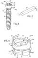
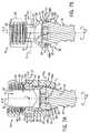
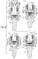
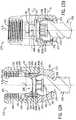
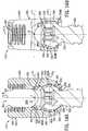
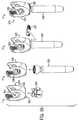
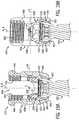
Fig. 1A is a perspective view of a bone fixation assembly constructed in accordance with one embodiment including a plurality of bone fixation elements connected by a bone fixation rod, and illustrated schematically as each being affixed to a vertebra;Fig. 1B is a perspective view of one of the bone fixation elements illustrated inFig. 1A constructed in accordance with one embodiment, including an anchor seat, a bone anchor, a collet, and a locking cap;Fig. 2 is a perspective view of the bone fixation rod illustrated inFig. 1A ;Fig. 3 is a perspective view of the bone anchor illustrated inFig. 1B ;Fig. 4A is a perspective view of the anchor seat illustrated inFig. 1B ;Fig. 4B is an enlarged portion of a guide provided by the anchor seat illustrated inFig. 4A ;Fig. 5A is an exploded perspective view of the locking cap illustrated inFig. 1B ;Fig. 5B is a top plan view of the locking cap illustrated inFig. 5A ;Fig. 5C is a sectional side elevation view of the locking cap illustrated inFig. 5B ;Fig. 6 is a perspective view of the collet illustrated inFig. 1B ;Fig. 7A is a sectional side elevation view of the bone fixation element illustrated inFig. 1B taken alongline 7A-7A, with the locking cap removed, to illustrate a bone fixation subassembly;Fig. 7B is a sectional side elevation view of the bone fixation subassembly illustrated inFig. 7A , and taken alongline 7B-7B ofFig. 1B ;Fig. 7C is a sectional side elevation view similar toFig. 7A , but showing the bone fixation element including a fixation rod extending through the anchor seat, and a locking cap affixed to the anchor seat;Fig. 7D is a sectional side elevation view similar toFig. 7B , but showing the bone fixation element illustrated inFig. 7C ;Fig. 8 is a schematic view illustrating a method for assembling the bone fixation element illustrated inFig. 1A ;Fig. 9A is a sectional side elevation view of a bone fixation subassembly constructed in accordance with an alternative embodiment, taken from the same orientation asFig. 7A ;Fig. 9B is a sectional side elevation view of the bone fixation illustrated inFig. 9A , taken from the same orientation asFig. 7B ;Fig. 10A is a top perspective view of a collet of the bone fixation subassembly illustrated inFigs. 9A-B ;Fig. 10B is a bottom perspective view of the collet illustrated inFig. 10A ;Fig. 11A is a perspective view of a bone fixation subassembly including an anchor seat extension constructed in accordance with an alternative embodiment;Fig. 11B is a perspective view of the anchor seat extension illustrated inFig. 11A ;Fig. 11C is a perspective view of the bone fixation subassembly illustrated inFig. 11A , with a potion cut away;Fig. 12A , is a sectional side elevation view of the bone fixation subassembly illustrated inFig. 11A , taken alongline 12A-12A;Fig. 12B , is a sectional side elevation view of the bone fixation subassembly illustrated inFig. 11A , taken alongline 12B-12B;Fig. 13 is a schematic view illustrating a method for assembling the bone fixation subassembly illustrated inFig. 11 ;Fig. 14A is a sectional side elevation view similar toFig. 12A , but of a bone fixation subassembly constructed in accordance with another embodiment including a collet extension;Fig. 14B is a sectional side elevation view similar toFig. 12A , but of the bone fixation subassembly illustrated inFig. 14A ;Fig. 15 is a perspective view of the collet extension illustrated inFig. 14A ;Fig. 16 is a schematic view illustrating a method for assembling the bone fixation subassembly illustrated inFigs. 14A-B ;Fig. 17 is a perspective view of a bone anchor installed in a collet in accordance with another alternative embodiment;Fig. 18 is a perspective view a bone fixation subassembly constructed in accordance with another embodiment, including the anchor and collet ofFig. 17 installed in an anchor seat, with a portion cut away;Fig. 19A is a sectional side elevation view of the bone fixation subassembly illustrated inFig. 18 , taken alongline 19A-19A;Fig. 19B is a sectional side elevation view of the bone fixation subassembly illustrated inFig. 18 , taken alongline 19B-19B;Fig. 20 is a sectional side elevation view similar the bone fixation subassembly ofFig. 19B , showing pivotal movement of the anchor seat relative to the bone anchor in the sagittal plane;Fig. 21A is a sectional side elevation view similar toFig. 19A , but of a bone fixation subassembly constructed in accordance with another alternative embodiment;Fig. 21B is a sectional side elevation view similar toFig. 19B , but of the bone fixation subassembly illustrated inFig. 21 A;Fig. 22 is a perspective view of a collet of the bone fixation subassembly illustrated inFig. 21 A;Fig. 23 is a perspective view of a collet of a bone fixation subassembly constructed in accordance with another embodiment;Fig. 24 is a schematic view illustrating a method for assembling the bone fixation subassembly illustrated inFig. 23 ; andFig. 25 is a sectional top plan view of the bone fixation subassembly illustrated at step 5 ofFig. 24 .- Certain terminology may be used in the following description for convenience only and should not be considered as limiting in any way. For instance, a
bone fixation assembly 20 includes one or morebone fixation elements 22, and fourbone fixation elements 22A-D as illustrated inFig. 1A . As shown inFig. 1B , eachbone fixation element 22 extends vertically along an axial direction A, and generally horizontally along a radial direction R extends perpendicular to the axial direction A. Thus, the radial direction R includes a longitudinal direction L and a lateral direction LA that extends perpendicular to the longitudinal direction L. It should be appreciated that the directional terms "longitudinal," "lateral," can likewise apply to thebone fixation assembly 20 as extending horizontally, and the directional term "transverse" can refer to a vertical direction. Thebone fixation element 22 defines anupper end 21 and alower end 23, such that the directional terms "upper" and "lower" and derivatives thereof refer to a direction from thelower end 23 towards theupper end 21, and from theupper end 21 towards thelower end 23, respectively. - The words "inward," "outward," "upper," "lower," "distal," and "proximal," refer to directions toward or away from, respectively, the geometric center of the
bone fixation assembly 20 and its components. The words, "anterior", "posterior", "superior," "inferior" and related words and/or phrases designate preferred positions and orientations in the human body to which reference is made and are not meant to be limiting. It should further be appreciated that while round structures define diameters as described herein, the round structures could be replaced with alternative (e.g., polygonal) structures which would define alternative cross-sectional dimensions opposed to diameters. The term "diameter" as used herein is intended to include all such alternatives unless otherwise specified. The terminology includes the above-listed words, derivatives thereof and words of similar import. - It should be appreciated that the directional terms are used herein with reference to the orientation of the
bone fixation assembly 20 and its components as illustrated, and that the actual orientation of thebone fixation assembly 20 and its components may change during use. For instance, the axial direction is illustrated as extending along a vertical direction, and the radial direction is illustrated as extending along a horizontal direction, however the directions that encompass the various directions may differ during use, depending, for instance, on the desired orientation of thebone fixation assembly 20 during use. Accordingly, the directional terms are used herein merely for the purposes of clarity and convenience only, in a non-limiting manner. - Referring now to
Fig. 1A , thebone fixation assembly 20 includes a plurality of bone fixation elements, such asbone fixation elements 22A-D, connected by afixation rod 24 that extends along a longitudinal axis L. Thebone fixation elements 22A-D each include abone anchor 30 that is implanted (e.g., screwed) into acorresponding vertebra 27A-D. Unless otherwise specified, thebone fixation assembly 20 and its components can be made from titanium-aluminum-niobium alloy (TAN), implant-grade 316L stainless steel, or any suitable alternative implant-grade material. - With continuing reference to
Fig. 1A , thebone fixation elements 22A-D will be described as and may be generally implanted in the spine, for instance at the pedicle portion of a lumbar, thoracic, or cervical vertebral body. In this regard, when thebone fixation elements 22A-D are joined by therod 24, theassembly 20 fixes the relative position of the vertebrae (illustrated schematically at 27A-D). Accordingly, thebone fixation elements 22A-D can be referred to as spine fixation elements or pedicle screw assemblies, thefixation rod 24 can be referred to as a spinal rod, and thebone fixation assembly 20 can be referred to as a spine fixation assembly. However, it should be appreciated that thebone fixation assembly 20 can also be used for fixation of other parts of the body, such as joints, long bones, or bones in the hands, face, feet, extremities, cranium, and the like. - As shown in
Fig. 2 , thefixation rod 24 is elongate along a longitudinal axis L, and includes abody 25 that is cylindrical or tubular in shape. The longitudinal axis L extends generally in a cranial-caudal direction, or in the sagittal plane, when the bone fixation assembly is affixed to the spine. Therod body 25 may include, but is not limited to, a solid body, a non-solid body, a flexible or dynamic body, or the like, and can assume any alternative shape as desired. It should thus be appreciated that thebone fixation assembly 20 is not limited in use to anyparticular fixation rod 24. - Referring now to
Fig. 1B , thebone fixation elements 22A-D of thebone fixation assembly 20 will now be described with respect to thebone fixation element 22. In particular, thebone fixation element 22 generally includes abone fixation subassembly 75, and a lockingcap 34. Thesubassembly 75 is illustrated as including abone anchor seat 26, acollet 28 disposed inside theanchor seat 26, a bone anchor 30 (shown as a threaded bone screw) having a head portion 33 (seeFig. 3 ) attached to thecollet 28. The lockingcap 34 is installed in theanchor seat 26 at a location above thecollet 28, such that thefixation rod 24 is located in arod slot 36 that is disposed, and as illustrated defined, between thecollet 28 and the lockingcap 34. As will be appreciated from the description below, thebone anchor 30 is free to pivot with respect to theanchor seat 26 in a desired plane, which can be the sagittal plane, and can further freely rotate relative to theanchor seat 26. Because pivotal motion of the bone anchor is limited to the desired plane, thebone fixation elements 22 can be referred to as a uni-planar bone fixation element, and the bone fixation assembly can be referred to as a uni-planar bone fixation assembly. - Referring also to
Fig. 3 , thebone anchor 30 is configured as a bone screw, or pedicle screw, that includes an externally threadedshaft 31 coupled at its upper end to an enlargedcurved head 33. Theshaft 31 extends axially along a central axis B of rotation, and can define any suitable diameter, length, and thread design so as to engage the underlying bone, such as a vertebra 27. Alternatively, theshaft 31 can be unthreaded so as to define a pin or a nail if desired. Thus, one skilled in the art will appreciate that thebone anchor 30 is not limited to any particular type ofshaft 31. Thebone anchor 30 may also be cannulated and fenestrated such that openings extend radially outward from a central hollow channel in a cannulated shaft to urge fluid out of thebone anchor 30 during injection or draw fluid into the central hollow channel from the radial sides of the anchor during extraction of material adjacent the anchor if desired. - The
bone anchor 30 further includes a vertically extendingneck 35 connected between theshaft 31 and thehead 33. Theneck 35 is illustrated as extending axially in a direction parallel to axis B, and includes anouter neck surface 37 that defines a neck diameter, which is less than the diameter of thehead 33. - The
head 33 can define a semi-spherical curvature, or can alternatively define any suitable curvature as desired to facilitate rotation with respect to thecollet 28 as is described in more detail below. Thehead 33 defines a pivot location that extends along a lateral pivot axis of rotation LAp that extends through the head in a direction parallel to the lateral axis LA. Thehead 33 further defines a pivot location that extends along a longitudinal axis of rotation LP that extends through the head in a direction parallel to the longitudinal axis L. Thehead 33 also includes adrive surface 39 configured to receive a corresponding tip of a drive tool, such as a screw driver configured to rotate thebone anchor 30 into engagement with the vertebrae 27 or other underlying bone surface. Thedrive surface 39 can define a hexagon, a star drive pattern, a Phillips head pattern, a slot for a screw driver, threads configured to receive corresponding threads of a threaded drive post, or any suitable drive tool engaging structure as desired. - Referring now to
Fig. 4A , theanchor seat 26 includes ananchor seat body 38 that can be described as a generally cylindrical tubular body extending centrally along an axial axis A that extends generally in the anterior-posterior direction in the sagittal plane when the bone fixation element is implanted in the underlying vertebra. Thus, as known by those having ordinary skill in the art, the longitudinal axis L and the axis A extend substantially in the sagittal plane when thebone fixation assembly 20 is fixed in the vertebrae 27. Thebody 38 includes abase 40 and a pair of spaced opposingarms 42 extending out (up in illustrated the orientation) from thebase 40. Thearms 42 can be substantially identically or identically constructed. Thearms 42 define corresponding upper ends 46 that are also the upper ends of thebody 38, and define anupper opening 48. Thebase 40 defines alower end 50 that is also the lower end of thebody 38, and defines alower opening 52. Thebody 38 defines anaxial bore 54 extending from thelower opening 52 to theupper opening 48. - The
body 38 includes a pair of spaced opposingsupport walls 56 and a pair of spaced opposingspacer walls 58 connected between thesupport walls 56. Thesupport walls 56 can be substantially identically or identically constructed, and thespacer walls 58 can likewise be substantially identically or identically constructed. Thearms 42 extend up fromrespective support walls 56, and can be shaped as desired. As illustrated, thearms 42 are arc-shaped with the axis of the arc passing through the plane of symmetry that bisects theanchor seat 26. Eacharm 42 extends circumferentially about its axis less than 180°, such as between 60° and 150°, for instance approximately 90 °. In one highly preferred embodiment, eacharm 42 extends circumferentially 90.5° about its axis. Accordingly, a gap G extends circumferentially between adjacent circumferentially outer ends of thearms 42. The opposing gaps G are in alignment with theaxial bore 54. Thearms 42 can be disposed radially opposite each other such that the gaps G, in combination with the aligned portion of theaxial bore 54, define a rod-receivingchannel 36 that is sized and configured to receive thefixation rod 24 such that thefixation rod 24 extends through thebone fixation element 22. Thus, the gaps G are aligned in the longitudinal direction. Thefixation rod 24 can thus extend through the opposing gaps G and theaxial bore 54. Thearms 42 define radially inner andouter surfaces inner surfaces 60 definethreads 62, and are configured to threadedly receive the lockingcap 34, as will now be described. - In particular, referring to
Figs. 5A-C , the lockingcap 34 is illustrated as aset screw 64 and asaddle 66 operatively coupled to theset screw 64. Theset screw 64 includes a generally cylindricalset screw body 65 havingexternal threads 68 configured to threadedly engage thethreads 62 formed on theinner surfaces 60 of thearms 42. In accordance with one embodiment, thethreads bone fixation element 22. The load flanks may converge so that the top surface of the thread and the bottom surface of the thread converge. The angle may be between 0 degrees (0°) and 30 degrees (30°), and in one embodiment can be about five degrees (5°). One skilled in the art will appreciate that the threads may take on any alternative form as desired, including negative load threads, perpendicular threads, buttress threads, or the like. - The externally threaded set
screw 64 generally provides flexibility when inserting thefixation rod 24 into theanchor seat body 38 such that thefixation rod 24 need not be completely reduced or seated within thebody 38 prior to engagement of the lockingcap 34. Theset screw 64 is configured to be tightened within theanchor seat 26 against thefixation rod 24. The lockingcap 34 may be constructed as desired for this purpose including, but not limited to, an externally threaded cap, a quarter-turn or partial-turn locking cap, a two-piece screw set, or the like. - The
set screw 64 is illustrated as including adrive surface 70 provided as an internal recess extending vertically down into the upper end of thescrew 64. The drive surface has any suitable shape configured to cooperate with a corresponding drive tool for threadedly securing theset screw 64 onto theanchor seat body 38. Thedrive surface 70 can define any shape as desired, for instance an external hexagon, a star drive pattern, a Phillips head pattern, a slot for a screw driver, a threading for a correspondingly threaded post, or the like. - With continuing reference to
Figs. 5A-C , thesaddle 66 includes asaddle body 72 having atransverse recess 74 extending up into the bottom end of thesaddle body 72. Therecess 74 can define a round surface that extends about a longitudinally extending axis, such that therecess 74 is configured to receive thefixation rod 24 at a rod-contactingsurface 76. The rod-contactingsurface 76 can include a desired surface finish that adds roughness, such as, for example, a knurl, bead blasting, grooves, or other textured finish that increases surface roughness and enhances rod push through strength. - The
saddle 66 can be coupled to theset screw 64 in any desired manner, including adhesion, mechanical fastening, and the like. In the illustrated embodiment, thesaddle 66 includes astem 78 extending centrally upward from thesaddle body 72. Thestem 78 is configured to be received in acentral bore 32 extending vertically into the lower end of theset screw body 65, and can be fastened within the central bore with a rivet 80 or other like fastener. Accordingly, thesaddle 66 is rotatable relative to theset screw 64, such that thesaddle 66 can self-align with thefixation rod 24 as theset screw 64 is being rotated with respect to theanchor seat 26, for instance when the lockingcap 34 is being tightened against thefixation rod 24. - Referring again to
Fig. 4A , and as described above, theanchor seat body 38 includes a pair of spaced opposingsupport walls 56 and a pair of spaced opposingspacer walls 58 connected between thesupport walls 56. Thearms 42 extend up fromrespective support walls 56, such that thespacer walls 58 are disposed between thearms 42. Each of thespacer walls 58 defines opposing upper ends 84 and lower ends 82 that can be shaped as desired. The upper ends 84 are round in accordance with the illustrated embodiment, such that the upper ends 84 and the circumferentially outer ends of thearms 42 are adjoined to generally define a U-shape from a horizontal view through the gaps G. Thus, the upper ends 84 define the lower end of the gaps G. - The upper ends 84 can be shaped to conform generally with the outer surface of the
fixation rod 24, such that the upper ends 84 receive and engage thefixation rod 24 during use. Alternatively, the upper ends 84 can be spaced slightly below the upper surface of thecollet 28, such that thecollet 28 supports thefixation rod 24 during use, as will be described in more detail below. - The
support walls 56 each define opposing inner andouter surfaces support walls 56 flare inward toward axis A in a downward direction from thearms 42, and terminate at respective lower ends 90. Theinner surfaces 86 of eachsupport wall 56 at thelower end 90 define a distance D therebetween that is less than the distance between opposing radially opposinginner surfaces 60 of thearms 42, and greater than the diameter of thehead 33 of thebone anchor 30. Theinner surfaces 86 flare radially inward toward the central axis A, and toward each other, along a downward direction, and are each connected to bottommost, and innermost, surfaces that define respectivelongitudinal guide walls 92. - Referring also to
Fig. 4B , eachguide wall 92 defines respective inner guide surfaces 93 that extend in a desired plane through which thebone anchor 30 is permitted to pivot relative to theanchor seat 26. In the illustrated embodiment, the desired plane is the sagittal plane SP. It should be appreciated in alternative embodiments that theanchor seat 26 can be constructed such that theguide walls 92 extend in any desired alternative plane, such as a plane defined by the medial-lateral and anterior-posterior directions. - Referring also to
Fig. 7A , the opposingguide walls 92 define a distance therebetween that is substantially equal to the diameter of theneck 35, such that theguide walls 92 are configured to abut opposing abutment surfaces of the bone anchor, which are illustrated as opposing sides of theouter neck surface 37 when thebone anchor 30 is disposed in theanchor seat 26. The opposing sides of theouter neck surface 37 are spaced along a lateral axis that is perpendicular to the longitudinal axis L. Accordingly, theguide walls 92 prevent thebone anchor 30 from pivoting along a first direction D toward eitherguide wall 92 with respect to theanchor seat 26, for instance about the longitudinal pivot axis LP. Thus, theguide walls 92 provide a guide or track that permits thebone anchor 30 to pivot along the guide or track only in a desired plane that is defined by the guide wall 92 (e.g., sagittal plane) and includes the axis A, and prevents thebone anchor 30 from pivoting in any other plane that 1) includes the axis A, and 2) intersects the desired plane. When theanchor 30 pivots in the desired (e.g., sagittal) plane, the axis of rotation B becomes angularly offset with respect to the central axis A of thesubassembly 75. - Alternatively, the
guide walls 92 can be spaced apart a distance greater than the diameter of theneck 35, but disposed within close proximity of thebone anchor 30, so as to limit pivotal movement of thebone anchor 30 relative to theanchor seat 34 in the first direction D in a plane that is perpendicular to the desired (e.g., sagittal plane), for instance about the longitudinal pivot axis LP. Thebone anchor 30 can pivot about the longitudinal pivot axis LP through a range of angles defined by the central anchor axis B and the central anchor seat axis A that is less than 10°, for instance less than 5°, such as 0°. The distance between the opposingguide walls 92 is less than the diameter of thehead 33 of thebone anchor 30, while theinner surfaces 86 define a distance therebetween that is slightly greater than the diameter of theanchor head 33. - Referring now to
Figs. 4 and7B , the lower ends 82 of thespacer walls 58 are connected between the outer ends of the opposingsupport walls 56, and extend in a direction substantially perpendicular to the guide walls and perpendicular to the longitudinal axis L. Furthermore, the lower ends 82 are upwardly displaced with respect to theguide walls 92. Accordingly, the lower ends 82 are positioned to permit thebone anchor 30 to pivot in a second direction E about the lateral pivot axis LAP along a second plane (e.g., the sagittal plane) relative to theanchor seat 26 until theneck 35 of thebone anchor 30 abuts one of the lower ends 82. In this regard, the lower ends 82 can be referred to as stops. Because the lower ends 82 are displaced above theguide walls 92, the bone anchor can pivot more in the second direction E than in the first direction D. For instance, as illustrated, thebone anchor 30 can pivot such that the central axis B of the bone anchor can be angularly offset with respect to the central axis A of theanchor seat 26 through a range of angles +/- between 0° and 90° with respect to the vertical, such as between 5° and 45°, including between 15° and 35°, forinstance 25° in the sagittal plane before theneck 35 abuts the lower ends 82. Theneck 35 of theanchor 30 can ride along theguide wall 92 as it pivots in the sagittal plane SP. - Referring now to
Fig. 6 , thecollet 28 includes acollet body 45 that defines a first orupper end 47 sized and configured to contact or support at least a portion of thefixation rod 24 when the rod is received within the rod-receivingchannel 36, and a second orlower end 49 sized and configured to contact or otherwise engage, directly or indirectly, a portion of thebone anchor head 33. Thecollet body 45 is annular, and thus defines anaxial bore 53 extending between and through the upper and lower ends 47 and 49. Theaxial bore 53 is aligned with theaxial bore 54 when thecollet 28 is installed in theanchor seat 26. - Referring to
Figs. 6 and7A-B , theupper end 47 defines radially opposing upwardly facingseat portions 51 having a curvature or semi-spherical shape corresponding to the outer surface of thefixation rod 24, and is therefore configured to receive or otherwise support at least a portion (e.g., a lower portion) of therod 24. Thelower end 49 defines aninner surface 55 defining a curvature or semi-spherical shape corresponding to the outer surface of theanchor head 33, and is therefore configured to receive or otherwise engage at least a portion of thehead 33, so that the head can rotate with respect to thecollet 28 and theanchor seat 26, and can further pivot with respect to thecollet 28 as permitted by theanchor seat 26. Because thebone anchor 30 can freely rotate about its axis of rotation B relative to theanchor seat 26, and thus theanchor seat 26 can likewise rotate about thebone anchor 30, the rod-receivingchannel 36 can be aligned with thefixation rod 24 without advancing or withdrawing thebone anchor 30 in or out of the underlying bone. Thus, thebone anchor 30 can maintain a constant insertion depth in the underlying bone (e.g., vertebra 27) while adjusting the orientation of the rod-receivingchannel 36. - The
collet 28 further includes a pair offlanges 57 extending up from theupper end 47 of thecollet body 45 at a location radially between theseat portions 51. A lockinglip 59 extends radially out from eachflange 57. As best shown inFig. 7A , theanchor seat 26 defines a pair of opposingrecesses 61 formed radially in the opposinginner surfaces 86 of thesupport walls 56 at a location below the threadedinner surfaces 60 of thearms 42. During operation, thecollet 28 can be inserted down into theanchor seat 26, thereby causing theflanges 57 to flex inwardly past the threadedinner surfaces 60, until thelips 59 clear the upper ends 63 of therecesses 61, at which point theflanges 57 snap back out so that thelips 59 are disposed in therecesses 61. Interference between thelips 59 and the upper ends 63 prevent thecollet 28 from backing out through the upper end of theanchor scat 26. Therecesses 61 further define a circumferential length substantially equal to that of theflanges 57 and lockinglips 59, such that thecollet 28 is rotationally fixed with respect to theanchor seat 26 in a position whereby theupper surface 47 is aligned with thefixation rod 24 when thefixation rod 24 is inserted into theanchor seat 26. - The
lower end 49 of thecollet 28 defines an outer diameter that is greater than the inner distance between theguide walls 92. Accordingly, thecollet 28 is unable to pass axially down through the lower end of theanchor body 26. Thelower end 49 includes one or more slots 67 (illustrated as a plurality of slots) extending radially therethrough so as to define opposing pluralities offingers collet 28 is disposed in theanchor seat 26 such that thelips 59 are disposed in therespective recesses 61, thefingers 69A are axially aligned with theguide walls 92, and thefingers 69B are axially aligned with the lower ends 82 of thespacer walls 58. Thus, as shown inFigs. 7A-B , when thecollet 28 andanchor 30 are installed in theanchor seat 24, thefingers anchor head 33 and the inner surfaces of thesupport walls 56 andspacer walls 58, respectively, as illustrated inFigs. 7A-B . The inner diameters defined by the opposingfingers anchor head 33 to prevent theanchor 30 from being removed from theanchor seat 26 in an axially downward direction. - The lower ends of the
fingers 69A terminate at a location above theguide walls 92, and the lower ends of thefingers 69B terminate at a location above the lower ends 82. Accordingly, thefingers anchor neck 35 and theguide walls 92 and lower ends 82, and thus do not interfere with the permissible movement of the bone anchors 30 relative to theanchor seat 26. Alternatively, one or both of the pluralities offingers 69A-B could extend below theanchor seat 26, and thus abut theanchor 30 in the manner described above with respect to theguide 92 and stopsurface 82 so as to direct movement of thebone anchor 30 in a desired direction (e.g., pivot in the sagittal plane). - Referring now to
Fig. 8 , a method for assembling abone fixation subassembly 75 includes atstep 1, inserting thebone anchor 30 vertically down through theaxial bore 54, such that theshaft 31 extends through thelower opening 52 of thelower end 50 of theanchor scat 26. Next, atstep 2, thecollet 28 is inserted into theaxial bore 54 to a location whereby the lockinglips 59 can engage thelowermost threads 62 of theinner surface 60 of thearms 42. Next, atstep 3, an upward force can be applied to thebone anchor 30 so as to insert theanchor head 33 into thelower end 49 of thecollet 28. The lockinglips 59 of thecollet 28 brace against theanchor seat 26 inside thethreads 62 to prevent the upward force applied by thescrew 28 from causing thecollet 28 to back out of the upper opening of theanchor seat 26. At step 4, a downward force is applied to thecollet 28, thereby inserting the lockinglips 59 into therecesses 61 in the manner described above, and locking theanchor 30 andcollet 28 in theanchor seat 26. - It should thus be appreciated that the
subassembly 75 can include thecollet 28 installed in theanchor seat 26, and thebone anchor 30 installed in thecollet 28. In alternative embodiments, a subassembly can be provided include the collet installed in the anchor seat without a bone anchor installed in the collet. In these embodiments, the bone anchor can be implanted into underlying bone before the anchor head is inserted into the collet. Theanchor 30 can comprise a pin or nail, or a screw as desired. It should be appreciated that thebone fixation subassembly 75 and the alternative bone fixation subassemblies described herein can likewise be referred to as spine fixation subassemblies when, for instance, they are configured for implantation into one or more vertebrae for vertebral fixation. - During use, because the
bone anchor 30 is rotatable with respect to thecollet 28 and theanchor seat 26, a driving tool can engage thedrive surface 39 of thehead 33 so as to insert the threadedshaft 31 into the underlying bone, as shown inFig. 1A . Next, as shown inFigs. 7A-D , theanchor seat 26 can be rotated about axis A in the direction of Arrow R about the full 360° range of angles so as to align the rod-receivingchannel 36 with the longitudinal axis of thefixation rod 24. Once thebone anchor 30 has reached a desired depth in the underlying vertebra, thefixation rod 24 can be inserted into thesubassembly 75. In particular, thefixation rod 24 is inserted into theaxial bore 54 either horizontally through the gaps G, or vertically down into theaxial bore 54. It should be appreciated that thefixation rod 24 will be seated in theupper end 47 of thecollet 28. - With continuing reference to
Figs. 7A-D , once therod 24 is installed in thesubassembly 75, the lockingcap 34 can be attached to thesubassembly 75 so as to fully assembly theanchor assembly 22. In this regard, it should be appreciated that thesubassembly 75 can further include thefixation rod 24 and/or the lockingcap 34. In the illustrated embodiment, theexternal threads 68 of theset screw 64 are rotated within theinner threads 62 of theanchor seat arms 42, thereby causing the set screw and saddle 66 to move axially down in theaxial bore 54. As thesaddle 66 approaches thefixation rod 24, thesaddle 66 is rotated with respect to theset screw 64 so as to bring the rod-contactingsurface 76 into alignment with thefixation rod 24. Once thesaddle 66 is aligned with thefixation rod 24, theset screw 64 is continuously threadedly inserted into thebone anchor 26, such that the lockingcap 34 can be tightened against therod 24, thereby applying a downward axial force to therod 24. The lockingcap 34 can be said to be in an initial position when installed in the lockingcap 34 but before applying an axial force against thefixation rod 24. The axial force applied to therod 24 by the lockingcap 34 is transmitted to thecollet 28, which causes thefingers 69A to ride along theinner surfaces 86 of thesupport wall 56, andfingers 69B to ride along the radially inner surfaces of thespacer walls 58. - As the
fingers 69A ride along theinner surfaces 86, they become radially inwardly displaced due to the inward flare of theinner surfaces 86, thereby radially biasing, or radially compressing, thefingers 69A against theanchor head 33. Likewise, as thefingers 69B ride axially down along the radially inner surfaces of thespacer walls 58, thefingers 69B become disposed between theanchor head 33 and thespacer walls 58, thereby radially compressing thefingers 69B against theanchor head 33. Increasing radial compression of thefingers 69A-B against theanchor head 33 causes frictional forces between thefingers 69A-B and theanchor head 33 that resist both rotation of theanchor 30 about the axis A relative to theanchor seat 26,collet 28, andfixation rod 24, and also resist pivoting of the anchor, for instance in the sagittal plane. When the locking cap is fully tightened to a locked position, the resulting frictional forces prevent theanchor 30 from movement relative to theanchor seat 26,collet 28, andfixation rod 24. Thus, the lockingcap 34 is configured to transmit a locking force onto thecollet 28 andbone anchor 30 to fix or lock the position of thebone anchor 30 relative to theanchor scat 26 andfixation rod 24. Furthermore, when the lockingcap 34 is in the locked position, thefixation rod 24 is captured between thesaddle 66 and the upper surface of thecollet 28 such that theanchor seat 26 is prevented from movement relative to thefixation rod 24. - It should be appreciated that any time after the
bone anchor 30 installed in theanchor seat 26 and before thebone anchor 30 is locked in place, thebone anchor 30 can be pivoted in the sagittal plane SP about the lateral pivot axis LAP in the manner described above, while thebone anchor 30 is prevented from pivoting in all other planes. Because theguide walls 92 prevent thebone anchor 30 from pivoting about an axis that is angularly offset with respect to the lateral pivot axis LAP in the illustrated embodiment, the surgeon is assured that theanchor 30 can only pivot in the sagittal plane SP, and will not cause the vertebrae 27 to become misaligned due to movement of thebone anchor 30 in a direction other than in the sagittal plane. Accordingly, thebone fixation assembly 20 incorporating thebone fixation elements 22 has particular utility in addressing spinal misalignments such as the rotational component of a scoliosis deformity. - In one particular method, the locking
cap 34 can be tightened against the rod to an intermediate position that sufficiently radially compresses thefingers 69A-B against thebone anchor 30 that prevents thebone anchor 30 from freely pivoting in the sagittal plane, for instance under gravitational forces, while allowing a surgeon to pivotally adjust the angular position of thebone anchor 30 in from an initial position in a desired plane to a desired position in the desired plane by applying a force to thebone anchor 30 that overcomes the friction between thebone anchor 30 and thefingers 69A-B. In the illustrated embodiment, the desired plane is the sagittal plane Once thebone anchor 30 is in the desired angular position in the sagittal plane, the lockingcap 34 can be further tightened to a locked position whereby thebone anchor 30 is locked in place in the desired angular position in the desired plane. It should be appreciated that theend cap 34 can be unthreaded from the locked position into the intermediate position or the initial position if it is desired to further adjust the angular position of thebone anchor 30. - It should be appreciated that the above-described method steps can be performed for each bone fixation element of the
bone fixation assembly 20 as desired. Furthermore, the method steps described above need not be performed in the order described, and it should be appreciated that that one or more of the steps can be omitted if desired. It should be further appreciated that while theguide walls 92 prevent thebone anchor 30 from pivoting in a first plane that intersects the sagittal plane relative to theanchor seat 26 andfixation rod 24, theguide walls 92 could alternatively be slightly spaced with respect to theneck 35, such that theanchor 30 can pivot about a first plane that intersects the second sagittal plane within an angular range that is less than the angular range that theanchor 30 can pivot in the sagittal plane. - Referring to
Figs. 1-8 generally, one or morebone fixation assemblies 20 can be provided as one or morebone fixation elements 22 provided as a bone fixation kit. The kit can include at least one of the following components: one or more bone anchors 30, one or more locking caps 34, one ormore collets 28, one ormore fixation rods 24, one or more anchor seats 26, and/or one or more preassembledbone fixation subassemblies 75, including abone anchor 30 andcollet 28 pre-installed in theanchor seat 26 in the manner described above. Thus, the surgeon can implant thebone anchor 30 of a plurality of subassemblies in an underlying bone, such as a vertebra, and the anchor seats of the subassemblies can be coupled to afixation rod 24 in the manner described above. It should further be appreciated that the components included in the kit may vary by at least one characteristic. For example, the components included in the kit can vary in size and shape, and/or they can be constructed in accordance with alternative embodiments as described herein, or they could be identically constructed with the same size and shape. For instance,fixation rods 24 and bone anchors 30 can be provided having different diameters and lengths, and the bone anchors 30 can be provided as screws and nails or pins. Alternatively, several kits can be provided, each individual kit including components corresponding to a particular size, and shape, and embodiment, wherein the size, shape, and/or embodiment of the components of the kits can vary from kit to kit. - While the
bone fixation element 22 has been illustrated and described in accordance with one embodiment, it should be appreciated that bone fixation elements, a bone fixation assembly incorporating the bone fixation elements, and bone fixation kits can be constructed in accordance with several alternative embodiments. - For instance, referring to
Figs. 9-10 , abone fixation subassembly 175 constructed in accordance with an alternative embodiment is illustrated including reference numerals corresponding to like elements of thebone fixation subassembly 75 incremented by 100. Thus, thebone fixation subassembly 175 can be constructed as described with respect to thebone fixation subassembly 75 except as otherwise noted. It should be appreciated that one or more up to all of the bone fixation elements of thebone fixation assembly 20 can include thebone fixation elements 22 or alternative bone fixation elements as described herein, one or more of which can include thebone fixation subassembly 75, thebone fixation subassembly 175, or any alternative bone fixation subassembly as described herein. - The
bone fixation subassembly 175 includes an anchor seat 126, and acollet 128 preinstalled in the anchor seat 126. Thesubassembly 175 can further include abone anchor 30 preinstalled in thecollet 128, which in turn is preinstalled in the anchor seat 126. Alternatively, thesubassembly 175 can include thecollet 128 preinstalled in the anchor seat 126, and thebone anchor 30 can be later installed as desired. - The anchor seat 126 includes an anchor seat body 138 extending centrally along the central axis A. The body 138 includes a
base 140 and a pair of spaced opposingarms 142 extending up from thebase 140. Thebase 140 defines alower end 150 that is also the lower end of the body 138, and defines a lower opening 152. The body 138 defines anaxial bore 154 extending from the lower opening 152 to theupper opening 148. - The
arms 142 extend up fromrespective support walls 156, and the opposingspacer walls 158 are connected between thesupport walls 156. Thearms 142 defineinternal threads 162 that are configured to engage theexternal threads 68 of the lockingcap 34 as described above. Thearms 142 further define gaps G therebetween that are configured to receive thefixation rod 24 as described above. Thesupport walls 156 flare radially inward toward axis A in a downward direction from thearms 142 toward thelower end 150. The lower ends 150, in combination with thecollet 128, limit pivotal movement of thebone anchor 30 to a single plane, such as the sagittal plane, as described above. Thebone anchor 30 can also rotate about its central axial axis B relative to thecollet 128 and anchor seat 126 in the manner described above. - The
collet 128 includes acollet body 145 that defines a first orupper end 147 sized and configured to contact or support at least a portion of thefixation rod 24 when the rod is received within the rod-receivingchannel 136, and a second orlower end 149 sized and configured to contact or otherwise engage, directly or indirectly, a portion of thebone anchor head 33. The upper and lower ends 147 and 149 are constructed as described above, except thecollet body 145 includes afinger extension 173 defining the bottom end of each of thefingers 169A. - Accordingly, when the
collet 128 is installed in the anchor seat 126 to provide the preassembledbone fixation subassembly 175, thefinger extensions 173 extend through the lower opening 152 of thebase 140. Thefingers 169A andfinger extensions 173 defineinner surfaces 155 that in combination define a curvature or semi-spherical shape corresponding to the outer surface of theanchor head 33, and is therefore configured to receive or otherwise engage at least a portion of thehead 33. The lower ends of thefingers 169B terminate at a location displaced above the lower ends of theextensions 173, and are disposed above the lower opening 152 of the base 140 when thecollet 128 is installed in the anchor seat 126. - The
bone fixation subassembly 175 is constructed by inserting thecollet 128 down through the top of the anchor seat 126 until the lockinglips 59 extend in the corresponding recesses 161. Thefingers 169A andextensions 173, along with thefingers 169B, are placed over thehead 33 of thebone anchor 30, and a downward force is applied until thefingers 169A-B andextensions 173 expand radially outward to capture thehead 33 of thebone anchor 30 therein. The threadedshaft 31 of thebone anchor 30 may already be implanted into bone prior to popping thecollet 128 over thehead 33 of thebone anchor 30. It should be appreciated that the diameter of theanchor shaft 31 is not limited by the diameter of the opening 152 of thebase 140. Thus, the diameter of theanchor shaft 31 can be greater than the opening 152 of thebase 140. Alternatively, the diameter of theanchor shaft 31 can be smaller than that of the opening 152, such that thebone anchor 30 can be inserted down through the upper opening of the anchor seat 126 and installed in thecollet 128 in the manner described above with respect to thebone fixation element 22. - The radially inner ends of the lower ends of the
finger extensions 173 defineguide walls 192 that are spaced apart a distance substantially equal to the cross-sectional dimension of theanchor neck 35. Theguide walls 192 therefore abut theneck 35 when thehead 33 is captured in thecollet 128. Accordingly, theguide walls 192 permit theanchor 33 to pivot only in a desired plane that is parallel to theguide walls 192, or about the lateral pivot axis LAP (e.g., the sagittal plane). The permitted angulation in the sagittal plane is limited by contact between theneck 35 and the lower ends of thespacer walls 158 in the manner described above with respect to thebone fixation element 22. Once thebone anchor 30 has been installed in thesubassembly 175, thebone anchor 30 is free to rotate with respect to thecollet 128 and the anchor seat 126 about the central axis B as described above, which can be coincident with the central axis A of the anchor seat 126, or angularly offset in the sagittal plane. Once the gaps G are aligned with the longitudinal axis L of thefixation rod 24, thefixation rod 24 and lockingcap 34 can be installed in thesubassembly 175 in the manner described above. - Referring now to
Figs. 11-13 , abone fixation subassembly 275 constructed in accordance with an alternative embodiment is illustrated including reference numerals corresponding to like elements of thebone fixation subassembly 75 incremented by 200. Thus, thebone fixation subassembly 275 can be constructed as described above with respect to one or both of the bone fixation subassemblies except as otherwise described. It should be appreciated that one or more up to all of the bone fixation elements of thebone fixation assembly 20 can include thebone fixation elements 22 or alternative bone fixation elements as described herein, one or more of which can include thebone fixation subassembly 275 as will now be described. - The
bone fixation subassembly 275 includes ananchor seat 226, and acollet 228 preinstalled in theanchor seat 226. Thesubassembly 275 can further include abone anchor 230 preinstalled in thecollet 228, which in turn is preinstalled in theanchor seat 226. Alternatively, the subassembly can include thecollet 228 preinstalled in theanchor seat 226, such that thebone anchor 230 can be later installed as desired. For instance, thebone anchor 230 can be installed into thesubassembly 275 interoperatively (e.g., after thebone anchor 630 has been affixed in a vertebrae). - The
anchor seat 226 includes ananchor seat body 238 extending centrally along the central axis A. Thebody 238 includes abase 240 and a pair of spaced opposingarms 242 extending up from thebase 240. Thebase 240 defines alower end 250 that is also the lower end of thebody 238, and defines a lower opening 252. Thebody 238 defines anaxial bore 254 extending from the lower opening 252 to the upper opening 248. Thearms 242 extend up fromrespective support walls 256, and the opposingspacer walls 258 are connected between thesupport walls 256. Thearms 242 defineinternal threads 262 that are configured to engage theexternal threads 68 of the lockingcap 34 as described above. Thearms 242 further define gaps G therebetween that are configured to receive thefixation rod 24 as described above. - The
anchor seat 226 includes ananchor seat extension 277 that is separate from theanchor seat body 238. Theextension 277 is configured to fasten to thebone anchor 230 prior to attaching thebone anchor 230 to thecollet 228. As will be appreciated below, theextension 277 is provided as a clip that can be snapped onto theneck 235 of thebone anchor 230. Theanchor seat extension 277 includes acircumferentially extending collar 279 and a pair of opposingposts 281 extending out (or vertically up, in the illustrated embodiment, from thecollar 279. Thecollar 279 extends circumferentially greater than 180° but less than 360°, and defines an inner diameter substantially equal to the outer diameter of the anchor neck 237. A pair oftabs 283 extend up from the radially inner ends of theposts 281. - The
anchor seat body 238 includes arecess 285 extending in thesupport walls 256 and one of thespacer walls 258 sized to receive theanchor seat extension 277. Therecess 285 is keyed to receive theposts 281 in thesupport walls 256, such that the circumferential collar extends along one longitudinal end of the collar body but not the other longitudinal end. The outer diameter of theanchor seat extension 277 is substantially equal to the outer diameter of thelower end 250 of theanchor seat body 238, such that the outer circumferential surface of theextension 277 is flush with the outer circumferential surface of theanchor seat body 238 when theextension 277 is disposed in therecess 285. The outer diameter defined by thetabs 283 is substantially equal to the inner diameter of thesupport walls 256. - As shown in
Fig. 13 , thesubassembly 275 is constructed atstep 1A by installing thecollet 228 in theanchor seat 226 in the manner described above. Separately, atstep 1B, theanchor seat extension 277 is attached to thebone anchor 230 by clipping thecollar 279 over theanchor neck 235. Next, atstep 2, theanchor body 238 is brought down onto theanchor head 233, which causes theanchor seat extension 277 to be inserted into therecess 285. Therecess 285 is keyed such that the extension posts 281 are aligned with thearms 242. As theanchor body 238 is brought down onto theanchor head 233, thecollet fingers 169B radially expand over theanchor head 233, and pop onto thehead 233. Thecollet fingers 169B are disposed circumferentially between the extension posts 281, and thecollet fingers 169A are shorter than thefingers 169B as shown inFigs. 12A-B . - In one embodiment, the
subassembly 275 is constructed after the completion ofstep 1A, and thebone anchor 230 andanchor extension 277 can be installed into thesubassembly 275 at a later time, for instance before or after thebone anchor 230 has been implanted in a bone, such as a vertebra. In another embodiment, thesubassembly 275 is constructed after the completion ofstep 2, whereby thebone anchor 230 is attached to thecollet 228. It should further be appreciated thatstep 1 A can be completed prior to step 1B or thatstep 1B can be completed prior to step 1 A. - Once the
bone anchor 230 has been installed in theanchor seat 226, theanchor 230 is free to rotate relative to theanchor seat 226 about the axis of rotation B in the manner described above. The bottom surface of theposts 281 abut theneck 233, and therefore provide a laterally spaced guide members, or a laterally extending guide, 292 that allows theanchor 230 to pivot in the sagittal plane, while preventing theanchor 230 from pivoting in any other angle that intersects the sagittal plane. When theanchor 230 pivots in the sagittal plane, the axis of rotation B is angularly offset with respect to the central axis A of thesubassembly 275. Theextension 277 does not extend entirely around theanchor neck 235, and thus defines a gap that is disposed on one longitudinal side of theanchor 230. Thus, theanchor 230 is free to pivot toward that longitudinal side in the sagittal plane until theanchor 230 abuts the lower end of therespective spacer wall 238, which provides a stop for theanchor 230. Thecollar 279 extends along the opposing longitudinal side of theanchor 230, and can be vertically flush with or above the bottom surface of the correspondingspacer wall 238 such that the spacer wall provides a stop with respect to angular movement of theanchor 230 in the sagittal plane. Alternatively, thecollar 279 could be disposed below the bottom surface of the correspondingspacer wall 238 such that thecollar 279 provides a stop with respect to angular movement of theanchor 230 in the sagittal plane. Thus, thecollar 279 can limit pivotal movement in one direction in the pivotal plane. Alternatively still, the radially inner surface of thecollar 279 could be radially outwardly displaced with respect to the radial inner surface of theposts 281, such that thecollar 279 does not abut theneck 235 and thus permits pivotal movement in the sagittal plane toward thecollar 279. - The
collar 279 can be disposed at the inferior end of theanchor seat 226 when the bone fixation element is implanted, such that theanchor 230 can pivot along a greater angular range toward the superior end in the sagittal plane than toward the inferior end. Alternatively, thecollar 279 can be disposed at the superior end of theanchor seat 226 when the bone fixation element is implanted, such that theanchor 230 can pivot along a greater angular range toward the superior end in the sagittal plane than toward the inferior end. - Once the
anchor seat 226 has been aligned with thefixation rod 24, and the position of the bone anchor has been located in the sagittal plane as desired, the lockingcap 34 can be locked in thesubassembly 275 in the manner described above. - Referring now to
Figs. 14-16 , abone fixation subassembly 375 constructed in accordance with an alternative embodiment is illustrated including reference numerals corresponding to like elements of thebone fixation subassembly 75 incremented by 300. Thus, thebone fixation subassembly 375 can be constructed as described with respect to one or all of the bone fixation subassemblies described above, except as otherwise noted. It should be appreciated that one or more up to all of the bone fixation elements of thebone fixation assembly 20 can include thebone fixation elements 22 or alternative bone fixation elements as described herein, one or more of which can include thebone fixation subassembly 375 as will now be described. - The
bone fixation subassembly 375 includes ananchor seat 326, and acollet 328 preinstalled in theanchor seat 326. Thesubassembly 375 can further include abone anchor 330 preinstalled in thecollet 328, which in turn is preinstalled in theanchor seat 326. Alternatively, thesubassembly 375 be provided with thecollet 328 preinstalled in theanchor seat 326, such that thebone anchor 330 can be later installed as desired. - The
anchor seat 326 includes ananchor seat body 338 extending centrally along the central axis A. Thebody 338 includes a base 340 and a pair of spaced opposingarms 342 extending up from the base 340. The base 340 defines alower end 350 that is also the lower end of thebody 338, and defines alower opening 352. Thebody 338 defines anaxial bore 354 extending from thelower opening 352 to the upper opening 348. Thearms 342 extend up fromrespective support walls 356, and the opposingspacer walls 358 are connected between thesupport walls 356. Thearms 342 define gaps G therebetween that are configured to receive thefixation rod 24 as described above. Thearms 342 further defineinternal threads 362 that are configured to engage theexternal threads 68 of the lockingcap 34 as described above. - The
collet 328 includes acollet extension 387 that is separate from thecollet body 345. Theextension 387 is configured to fasten to thebone anchor 330 after thebone anchor 330 has been attached to thecollet 328. As will be appreciated below, theextension 387 is provided as a clip that can be snapped onto theneck 335 of thebone anchor 330. While thebone anchor 330 is illustrated as a nail or a pin, it should be appreciated that theanchor 330 could alternatively comprise a screw. Thecollet extension 387 includes acircumferential collar 389 and a pair of opposingposts 391 extending out (or vertically up in the illustrated orientation) from thecollar 389. Theposts 391 also flare radially outward along a vertically upward direction of travel. Thecollar 389 extends circumferentially greater than 180° but less than 360°, defines an inner diameter substantially equal to the inner diameter of thecollet body 345, and an outer diameter substantially equal to the outer diameter of thecollet body 345. - The
collet body 345 is keyed to receive thecollet extension 387 in a predetermined orientation. In particular, thefingers 369A that are aligned with thearms 342 are shorter than the remainingfingers 369B. Accordingly, thecollet extension 387 can be inserted into theanchor seat 326 such that theposts 391 are circumferentially aligned with, and located between, thefingers 369B. The circumferential collar extends along one longitudinal end of the collar body but not the other longitudinal end. - The
subassembly 375 is constructed using a method that begins at step 1) wherein thecollet 328 is installed in theanchor seat 326 by inserting thecollet 328 vertically upward into thelower opening 352 of theanchor seat body 338, in the manner described above. In one embodiment, the kit can include thesubassembly 375 as including theanchor seat 326 and the installedcollet 328. Next, atstep 2, theanchor body 338 is brought down onto the anchor head 333 (or theanchor head 333 is brought up into the anchor body 338), thereby causing thecollet fingers 169A-B to expand radially over thehead 333 and snap down over thehead 333 to secure the anchor therein. Atstep 3, thecollet extension 387 is clipped around theneck 335, such that theposts 391 extend into a gap between the lower ends ofadjacent fingers 369A. Thus, thecollet body 345 is keyed such that theposts 391 are vertically aligned with thearms 342. Thesubassembly 375 is thus provided at step 4. - Thus,
Fig. 16 illustrates the subassembly as including theanchor seat 326 and thecollet 328 installed in theanchor seat 326, thecollet extension 387 clipped onto thebone anchor 330, and thebone anchor 330 andcollet extension 387 attached to theanchor seat 326 andcollet 328. In an alternative embodiment, thesubassembly 375 can include the anchor seat and thecollet 328 without theanchor 330 andextension 387 installed. Theanchor 330 can be implanted into the underlying bone (e.g., vertebra) before or after thecollet extension 387 is clipped onto the neck, and prior to or after theanchor 330 is attached to thecollet 328. In this regard it should be appreciated that theanchor 330 is freely rotatable within thecollet 328 andextension 387 with respect to theanchor seat 326. - The bottom surface of the posts 381 abut the
neck 333, and therefore provide a laterally extendingguide 392 that allows theanchor 330 to pivot in the sagittal plane, while preventing theanchor 330 from pivoting in any other angle that intersects the sagittal plane. The extension 377 does not extend entirely around theanchor neck 335, and thus defines a gap that is disposed on one longitudinal side of theanchor 330. Thus, theanchor 330 is free to pivot toward that longitudinal side in the sagittal plane until theanchor 330 abuts the lower end of therespective spacer wall 338, which provides a stop for theanchor 330 in the sagittal plane. The collar 379 extends along the opposing longitudinal side of theanchor 330, and can be vertically flush with or above the bottom surface of the correspondingspacer wall 338 such that the spacer wall provides a stop with respect to angular movement of theanchor 330 in the sagittal plane. Alternatively, the collar 379 could be disposed below the bottom surface of the correspondingspacer wall 338 such that the collar 379 provides a stop with respect to angular movement of theanchor 330 in the sagittal plane. Thus, the collar 379 can limit pivotal movement in one direction in the pivotal plane. Alternatively still, the radially inner surface of the collar 379 could be radially outwardly displaced with respect to the radial inner surface of the posts 381, such that the collar 379 does not abut theneck 335 and thus permits pivotal movement in the sagittal plane toward the collar 379. - The collar 379 can be disposed at the inferior end of the
anchor seat 326 when the bone fixation element is implanted, such that theanchor 330 can pivot along a greater angular range toward the superior end in the sagittal plane than toward the inferior end. Alternatively, the collar 379 can be disposed at the superior end of theanchor seat 326 when the bone fixation element is implanted, such that theanchor 330 can pivot along a greater angular range toward the superior end in the sagittal plane than toward the inferior end. - Once the
anchor seat 326 has been aligned with thefixation rod 24, and the position of thebone anchor 330 has been located in the sagittal plane as desired, the lockingcap 34 can be locked in thesubassembly 375 in the manner described above. - Referring now to
Figs. 17-20 , abone fixation subassembly 475 constructed in accordance with an alternative embodiment is illustrated including reference numerals corresponding to like elements of thebone fixation subassembly 75 incremented by 400. Thus, thebone fixation subassembly 475 can be constructed as described with respect to one or all of the bone fixation subassemblies, except as otherwise noted. It should be appreciated that one or more up to all of the bone fixation elements of thebone fixation assembly 20 can include thebone fixation elements 22 or alternative bone fixation elements as described herein, one or more of which can include thebone fixation subassembly 475 as will now be described. - The
bone fixation subassembly 475 includes ananchor seat 426, and acollet 428 preinstalled in theanchor seat 426. Thesubassembly 475 can further include abone anchor 430 that can be preinstalled in thecollet 428 as part of thesubassembly 475 provide in the kit, or thebone anchor 430 can be provided separately, and later installed in thesubassembly 475, for instance before or after being implanted in an underlying bone. The anchor can comprise a pin or nail, or a screw as desired. - The
anchor seat 426 includes ananchor seat body 438 extending centrally along the central axis A. Thebody 438 includes abase 440 and a pair of spaced opposingarms 442 extending up from thebase 440. Thebase 440 defines alower end 450 that is also the lower end of thebody 438, and defines alower opening 452. Thebody 438 defines anaxial bore 454 extending from thelower opening 452 to the upper opening 448. Thearms 442 extend up fromrespective support walls 456, and the opposingspacer walls 458 are connected between thesupport walls 456. Thearms 442 define gaps G therebetween that are configured to receive thefixation rod 24 as described above. Thearms 442 further defineinternal threads 462 that are configured to engage theexternal threads 68 of the lockingcap 34 as described above. - The
collet 428 includes acollet body 445 that defines a first orupper end 447 sized and configured to contact or support at least a portion of thefixation rod 24 when the rod is received within the rod-receivingchannel 436, and a second orlower end 449 sized and configured to contact or otherwise engage, directly or indirectly, a portion of thebone anchor head 33. The upper and lower ends 447 and 449 are generally constructed as described above, with respect to thecollet 28, except the collet body includesfingers 469 of the same vertical length. Of course, it should be appreciated that one or more of thefingers 469 can extend down a greater or lesser difference than one or more of the other fingers. - The
collet 428 further includes a pair of radially opposingprotrusions 493 projecting radially inward from the upper ends of thecollet flanges 457. Whencollet 428 is installed in theanchor seat 426, theflanges 457 are located in the recesses 461 such that theprotrusion 493 is disposed radially centrally with respect to thearms 442 when thecollet 428 is installed in the anchor seat. Eachprotrusion 493 defines alower vertex 495 and upwardlyangled walls 497 extending longitudinally out from thevertex 495. Whenanchor head 333 is in thecollet fingers 469, thevertex 495 abuts the upper end of theanchor head 433, which can be flat in a radial direction perpendicular to the axis of rotation B. - As illustrated in
Fig. 20 , theprotrusion 493 permits theanchor 430 to pivot in a desired plane (e.g., the sagittal plane) relative to thecollet 428 andanchor seat 426, while interference between thevertex 495 and theanchor head 433 prevents theanchor 430 from pivoting in any plane that intersects the sagittal plane. In particular, theanchor 430 can pivot in the desired plane through an angular range defined by the axis A and pivoted axes of rotation B' of thebone anchor 430. Thus, theprotrusions 493 provide a guide that permits theanchor 430 to pivot in the desired plane while preventing pivotal movement of the bone anchor in all other planes that intersect the sagittal plane. Theanchor 430 can freely rotate about its axis B with respect to thecollet 428 and theanchor 426 in the manner described above. - The
bone fixation subassembly 475 is constructed by inserting thecollet 428 down through the top of theanchor seat 426 until theflanges 457 are locked in the corresponding recesses 461. The fingers 469A are placed over thehead 33 of thebone anchor 30, and a downward force is applied against theanchor 430 until the fingers 169 expand radially outward to capture thehead 433 of thebone anchor 430 therein. The threaded shaft 431 of thebone anchor 430 may already be implanted into bone prior to popping thecollet 428 over theanchor head 433. - Once the
anchor seat 426 has been aligned with thefixation rod 24, and the position of thebone anchor 430 has been located in the sagittal plane as desired, the lockingcap 34 can be locked in thesubassembly 475 in the manner described above. - Referring now to
Figs. 21-22 , abone fixation subassembly 575 constructed in accordance with an alternative embodiment is illustrated including reference numerals corresponding to like elements of thebone fixation subassembly 75 incremented by 500. Thus, thebone fixation subassembly 575 can be constructed as described above with respect to one or all of the bone fixation subassemblies, except as otherwise noted. It should be appreciated that one or more up to all of the bone fixation elements of thebone fixation assembly 20 can include thebone fixation elements 22 or alternative bone fixation elements as described herein, one or more of which can include thebone fixation subassembly 575 as will now be described. - The
bone fixation subassembly 575 includes ananchor seat 526, and acollet 528 preinstalled in theanchor seat 526. Thesubassembly 575 can further include abone anchor 530 that can be preinstalled in thecollet 528 as part of thesubassembly 575 provide in the kit, or thebone anchor 530 can be provided separately, and later installed in thesubassembly 575, for instance before or after being implanted in an underlying bone. Theanchor 530 is illustrated as a pin or nail, though theanchor 530 could alternatively be constructed as a screw. - The
anchor scat 526 includes ananchor scat body 538 extending centrally along the central axis A. Thebody 538 includes abase 540 and a pair of spaced opposingarms 542 extending up from thebase 540. Thebase 540 defines alower end 550 that is also the lower end of thebody 538, and defines alower opening 552. Thebody 538 defines anaxial bore 554 extending from thelower opening 552 to theupper opening 548. Thearms 542 extend up fromrespective support walls 556, and the opposingspacer walls 558 are connected between thesupport walls 556. Thearms 542 define gaps G therebetween that are configured to receive thefixation rod 24 as described above. Thearms 542 further defineinternal threads 562 that are configured to engage theexternal threads 68 of the lockingcap 34 as described above. - The
collet 528 includes acollet body 545 that defines a first orupper end 547 sized and configured to contact or support at least a portion of thefixation rod 24 when the rod is received within the rod-receivingchannel 536, and a second orlower end 549 sized and configured to contact or otherwise engage, directly or indirectly, a portion of thebone anchor head 33. The upper and lower ends 547 and 549 are generally constructed as described above, with respect to thecollet 428, except the collet body defines aU-shaped recess 599 extending radially inward into the radially outer surface of eachflange 557. Therecess 599 is configured to engage mating structure of theanchor seat 226 that prevents thecollet 528 from inadvertently backing out of theanchor seat 226 during use. - The
collet 528 further includes an interior threadedsurface 601 disposed axially above theprotrusion 593, which can receive corresponding threads of an insertion tool when assembling thesubassembly 575. The protrusion, however, extends radially inward with respect to theprotrusion 493, such that it engages the upper surface of aflat ledge 603 extending circumferentially about theanchor head 533. It should thus be appreciated that theflat ledge 603 defines a pair of opposing abutment surfaces that extend along a lateral axis that extends perpendicular to the longitudinal axis L defined by the opposing gaps G. Theanchor 530 can therefore pivot in a desired (e.g., sagittal) plane about theprotrusion 593 as described above. Additionally, as described above, thebone anchor 530 is free to rotate within thecollet 528 relative to theanchor seat 526 as described above. - The
bone fixation subassembly 575 is constructed by inserting thecollet 528 down through the top of theanchor seat 526 until theflanges 557 are locked in the corresponding recesses 561. Thefingers 569 are placed over thehead 33 of thebone anchor 30, and a downward force is applied against theanchor 530 until the fingers 169 expand radially outward to capture thehead 533 of thebone anchor 530 therein. The threaded shaft 531 of thebone anchor 530 may already be implanted into bone prior to popping thecollet 528 over theanchor head 533. Alternatively, thebone anchor 530 can be installed in thecollet 528, and subsequently implanted into underlying bone. Theinternal threading 601 of thecollet 528 allows for the use of a special driver instrument having an engagement feature,e.g., a T25 feature, which can mate with the screwdriver to further stabilize thebone anchor 530 as it is implanted into the underlying bone. - Once the
anchor seat 526 has been aligned with thefixation rod 24, and the position of thebone anchor 530 has been located in the sagittal plane as desired, the lockingcap 34 can be locked in thesubassembly 575 in the manner described above. - Referring now to
Figs. 23-25 , abone fixation subassembly 675 constructed in accordance with an alternative embodiment is illustrated including reference numerals corresponding to like elements of thebone fixation subassembly 75 incremented by 600. Thus, thebone fixation subassembly 675 can be constructed as described above with respect to one or all of the bone fixation subassemblies, except as otherwise noted. It should be appreciated that one or more up to all of the bone fixation elements of thebone fixation assembly 20 can include thebone fixation elements 22 or alternative bone fixation elements as described herein, one or more of which can include thebone fixation subassembly 675 as will now be described. - The
bone fixation subassembly 675 includes ananchor seat 626, and acollet 628 preinstalled in theanchor seat 626. Thesubassembly 675 can further include abone anchor 630 that can be preinstalled in thecollet 628 as part of thesubassembly 675 provide in the kit, or thebone anchor 630 can be provided separately, and later installed in thesubassembly 675, for instance before or after being implanted in an underlying bone. Theanchor 630 is illustrated as a pin or nail, though theanchor 530 could alternatively be constructed as a screw. - The
anchor seat 626 extends centrally along the central axis A, and includes a pair of spaced opposingarms 642 extending up fromrespective support walls 656. The opposingspacer walls 658 are connected between thesupport walls 656. Theanchor seat 626 defines alower end 650 that defines alower opening 652. An axial bore 654 extends from thelower opening 652 to theupper opening 648. Thearms 642 define gaps G therebetween that are configured to receive thefixation rod 24 as described above. Thearms 642 further defineinternal threads 662 that are configured to engage theexternal threads 68 of the lockingcap 34 in the manner described above. - The
collet 628 includes acollet body 645 that defines a first orupper end 647 sized and configured to contact or support at least a portion of thefixation rod 24 when the rod is received within the rod-receivingchannel 636, and a second orlower end 649 sized and configured to contact or otherwise engage, directly or indirectly, a portion of thebone anchor head 33. The upper and lower ends 647 and 649 are generally constructed as described above, with respect to thecollet 528, except eachflange 657 includes a pair of opposingvertical ribs 707 spaced apart a distance by agap 709. The outer circumferential edges of theribs 707 are spaced apart substantially the same distance as the circumferential edges of therecess 661 formed in the inner surface of thesupport walls 656. As a result, when thecollet 628 is inserted into theanchor seat 626, theribs 707 become disposed in therecess 661. Thecollet 628 further includes an inner threadedsurface 701, andprotrusions 693 disposed below the threadedsurface 701. Theprotrusions 693 define a guide that allows thebone anchor 30 to pivot relative to the anchor seat in the sagittal plane, in the manner described above. - The
bone anchor 630 includes a pair of opposingflat ledges 703 extending circumferentially around theanchor head 633 in the manner described above. The remainder of theanchor head 633 can be round in the manner described above. Thus, theledges 703 are configured to abut the lower end of theprotrusions 693 when thecollet 628,anchor 630, andfixation rod 24 are installed in theanchor seat 626, as will now be described with respect toFigs. 24-25 . - As illustrated, the
bone fixation subassembly 675 is constructed by inserting thecollet 628 down through the top of theanchor seat 626 to an initial insertion position atstep 1, until theflanges 657 are disposed in the correspondingrecesses 661 in the manner described above. When thecollet 628 is in the initial insertion position, theupper end 647 of the collet can be aligned with the gaps G. Next, atstep 2, thebone anchor 630 is inserted into thelower end 652 of theanchor seat 626, thereby popping thefingers 669 over theanchor head 633 so as to attach theanchor 630 to thecollet 628. Interference between thefingers 669 and the upper end of thesupport walls 656 prevents thecollet 628 from backing out of theanchor seat 626 in response to the upwardly directed force applied by theanchor 630. Thebone anchor 630 can be inserted into theanchor seat 626 andcollet 628 when assembling thesubassembly 675, or after thesubassembly 675 has been assembled, for instance interoperatively (e.g., after thebone anchor 630 has been affixed in a vertebrae). In the position illustrated inFig. 2 , the upper ends 647 of thecollet 628 are angularly offset with respect to the rod-receivingchannel 636. As illustrated, the upper ends 647 are oriented perpendicular with respect to thechannel 636. - Once the
anchor head 633 is captured in thefingers 669, a downward force is applied on theanchor 630 relative to theanchor seat 626 atstep 3, which brings thecollet 628 to an intermediate insertion position, whereby thefingers 669 bear against thesupport walls 656 andspacer walls 658. In the intermediate insertion position the lower ends of thefingers 669 are aligned with the lower ends of thesupport walls 656 andspacer walls 658. As thecollet 628 moves to the intermediate insertion position, theflanges 657 flare radially inward out of engagement with therecesses 661, and bear against the radially inner surfaces of thesupport walls 656. - It should be appreciated that in the intermediate insertion position, the
flanges 657 of thecollet 628 are disposed in the rod-receivingchannel 636, and thus positioned to interfere with thefixation rod 24 when the fixation rod is inserted. Because theflanges ledges 703 are not disposed in therecess 661, thecollet 628, and thus thebone anchor 633, is unimpeded with respect to pivotal movement about any radial axis about a 360° range with respect to theanchor seat 626, and therefore along any corresponding plane as desired, including the sagittal plane and any other plane angularly offset with respect to the sagittal plane. Theanchor 630 is further able to freely rotate about its central axis B relative to thecollet 628 and theanchor seat 626. - At step 4, the
collet 628 is rotated in the direction of Arrow A about axis A, until theflanges 657 are brought into alignment with the corresponding recesses 661. As shown inFig. 25 , theanchor scat 626 includes aretention dimple 711 extending radially inward from eachsupport wall 656 at a location circumferentially centrally disposed in thecorresponding recess 661. As thecollet 628 is rotated in the direction of Arrow A, one of each pair ofribs 707 cams over thedimple 711. Until eachdimple 711 is disposed in thecorresponding gap 709. Interference between thedimple 711 and theribs 707 therefore resists rotation of thecollet 628 relative to theanchor seat 626. As shown in step 5 ofFig. 24 , once thecollet 628 is positioned radially such that thedimples 711 are disposed in thegaps 709, thecollet 628 is unable to freely rotate or pivot relative to theanchor seat 626. Because theprotrusions 693 are aligned with, and abut, theledges 703 of theanchor 630, theprotrusions 693 provide a guide that prevents pivotal movement of theanchor 630 relative to theanchor seat 626 in all planes other than the sagittal plane as described above. Furthermore, when thedimples 711 are disposed in thegaps 709, the upper ends 647 of thecollet 626 are aligned with the rod-receivingchannel 636, thereby providing a seat for thefixation rod 24 in the manner described above. - In certain embodiments, when the
dimples 711 are disposed in thegaps 709, interference between thedimples 711 and theflanges 707 prevent inadvertent rotation of thecollet 628 relative to theanchor seat 626 that would bring the flange out of therecess 661. However, deliberate rotation of thecollet 628 about axis A relative to the anchor seat, for instance with a tool that engages theinternal threads 701, can cause theflange 657 to flex radially inward as theribs 707 cam over the dimples 71 1. Once theflange 657 flexes inward, thedimple 711 is no longer disposed in thegap 709. As thecollet 628 is further rotated, theflange 657 rotates to a position circumferentially betweenrecesses 661, whereby thecollet 628 andbone anchor 630 can freely pivot and rotate relative to theanchor seat 626 as described above. - In this manner, in instances where the
bone anchor 630 is inserted into the underlying vertebra, and thesubassembly 675 including theanchor seat 626 andcollet 628 are attached to thebone anchor 630 interoperatively, a surgical instrument could rotate thecollet 628 between its locked position whereby thedimples 711 are disposed in thegaps 709 and its unlocked position whereby theflanges 657 are disposed outside of therecesses 661. - When the
collet 628 is in the unlocked position, thebone anchor 630 is permitted to pivot both in the sagittal plane and in any other plane angularly offset with respect to the sagittal plane about a 360° range. When thecollet 628 is in the locked position, thebone anchor 630 is permitted to pivot only in the sagittal plane relative to theanchor seat 626. Once theanchor seat 626 has been aligned with thefixation rod 24, and the position of thebone anchor 630 has been located as desired, the lockingcap 34 can be locked in thesubassembly 675 in the manner described above. - It should be appreciated that the illustrations and discussions of the embodiments shown in the figures are for exemplary purposes only, and should not be construed limiting the disclosure. One skilled in the art will appreciate that the present disclosure contemplates various embodiments. It should be further appreciated that the features and structures described and illustrated in accordance one embodiment can apply to all embodiments as described herein, unless otherwise precluded. For instance, while the collet provides a guide in certain embodiments and the anchor seat comprises a guide in other embodiments, it should be appreciated that the above-described features of the collet could be combined with those of the anchor seat such that at least one, or both, of the collet and anchor seat provide a guide that prevents angular movement of the bone anchor is all planes other than the desired plane. It should be understood that the concepts described above with the above-described embodiments may be employed alone or in combination with any of the other embodiments described above.
- Preferred Embodiments of the invention are defined in
paras 1 to 20 - 1. A bone fixation subassembly configured to receive a fixation rod and a locking cap,the bone fixation subassembly comprising:
- an anchor seat including an anchor seat body extending along a central axis and defining an upper end and a lower end, wherein the upper end comprises a pair of opposing fixation rod-receiving gaps therebetween that are spaced along a longitudinal axis, and a bore disposed between the rod-receiving gaps; and a collet including a collet body disposed in the anchor seat, the collet body configured to attach to a bone anchor that extends along an axis of rotation, wherein a bone anchor attached to the collet is permitted to rotate about the axis of rotation relative to the anchor seat, and the bone anchor is further permitted to pivot relative to the anchor seat along a desired plane and prevented from pivoting in another plane that includes the central axis and is angularly offset with respect to the desired plane.
- 2. The bone fixation subassembly as recited in
para 1, wherein the bone anchor is permitted to pivot about an axis that is perpendicular to the longitudinal axis. - 3. The bone fixation subassembly as recited in
para 1, wherein the collet defines an expandable lower end comprising a plurality of fingers separated by slits, the fingers are sized to capture a head of the bone anchor therein. - 4. The bone fixation subassembly as recited in
para 3, wherein the fingers comprise extensions that extend below the anchor seat body. - 5. The bone fixation subassembly as recited in
para 1, further comprising a guide configured to engage an abutment surface of the bone anchor so as to direct pivotal movement of the bone anchor relative to the anchor seat in the desired plane. - 6. The bone fixation subassembly as recited in para 5, wherein the guide is configured to abut opposing abutment surfaces of the bone anchor that are separated along an axis that is perpendicular to the longitudinal axis.
- 7. The bone fixation subassembly as recited in para 6, wherein the upper end of the anchor seat body comprises a pair of opposing arms extending up from the lower end of the anchor seat body, the gaps are disposed between the arms, and the guide comprises the lower end of the anchor body at a location aligned with the arms.
- 8. The bone fixation subassembly as recited in para 7, wherein the lower end of the anchor body are configured to be displaced from the abutment surfaces at locations between the guides when the guides abut the abutment surfaces.
- 9. The bone fixation subassembly as recited in para 6, wherein the guide comprises a pair fingers of the collet.
- 10. The bone fixation assembly as recited in para 7, further comprising the bone anchor including an anchor body configured to be implanted in an underlying bone, an anchor head captured in the collet, and an anchor neck disposed between the anchor body and the anchor head, wherein the opposing abutment surfaces comprise the anchor neck.
- 11. The bone fixation subassembly as recited in para 10, further comprising an extension configured to attach to the neck, the extension including a pair of spaced posts connected by a collar, wherein the guide comprises the spaced posts.
- 12. The bone fixation subassembly as recited in para 11, wherein the extension clip attaches to the neck prior to capturing the head in the collet.
- 13. The bone fixation assembly as recited in para 6, further comprising the bone anchor including an anchor body configured to be implanted in an underlying bone, an anchor head captured in the collet, and an anchor neck disposed between the anchor body and the anchor head, wherein the opposing abutment surfaces comprise a flat ledge formed in the anchor head.
- 14. The bone fixation assembly as recited in para 13, wherein the guide comprises a projection extending down from the collet body.
- 15. The bone fixation assembly as recited in para 13, wherein the collet is configured to be installed in the anchor seat in an unlocked position whereby the anchor can pivot relative to the anchor seat about an axis angularly offset from the desired plane, and the collet is configured to be moved to a locked position whereby the anchor can only pivot in the desired plane.
- 16. The bone fixation assembly as recited in
para 1, wherein the bone fixation assembly is a spine fixation assembly comprising the anchor screw configured to be implanted in a vertebra. - 17. A bone fixation assembly comprising:
- a plurality of bone fixation subassemblies, each subassembly including:
- an anchor seat including an anchor seat body defining a base and a pair of opposing arms extending out from the base, wherein the arms define rod-receiving gaps therebetween disposed along a longitudinal axis; a collet including a collet body disposed in the anchor seat;
- a bone anchor extending along an axis of rotation, wherein the bone anchor is configured to be attached to the collet body such that the bone anchor can rotate about the axis of rotation relative to the anchor seat; and a guide that permits the bone anchor to pivot along a desired plane relative to the anchor seat while preventing the bone anchor from pivoting in another plane angularly offset with respect to the desired plane relative to the anchor seat; a fixation rod configured to extend through the rod-receiving gaps of the anchor seat; and a locking cap configured to attach to the arms, wherein the locking cap is movable to a locked position whereby the collet body is biased against the bone anchor so as to lock the bone anchor with respect to at least one of rotation about the axis of rotation and pivotal movement in the desired plane.
- a plurality of bone fixation subassemblies, each subassembly including:
- 18. A bone fixation kit comprising;
a bone anchor extending along an axis of rotation;
an anchor seat including an anchor seat body defining an upper end and a lower end, wherein the upper end comprises a pair of opposing fixation rod-receiving gaps therebetween that are spaced along a longitudinal axis, and a bore disposed between the rod-receiving gaps; and a collet including a collet body disposed in the anchor seat, the collet body configured to attach to the bone anchor, such that the bone anchor can rotate about the axis of rotation relative to the anchor seat, and the bone anchor can pivot in the sagittal plane about an axis that is perpendicular to the longitudinal axis. - 19. The bone fixation kit as recited in para 18, wherein the collet is attached to the bone anchor.
- 20. The bone fixation kit as recited in para 18, further comprising a bone fixation rod configured to be extend through the fixation rod-receiving gaps, and a locking cap configured attached to the end cap body so as to lock the screw with respect to rotational and pivotal movement with respect to the anchor seat.
Claims (14)
- A bone fixation subassembly configured to receive a fixation rod and a locking cap, the bone fixation subassembly comprising:an anchor seat including an anchor seat body extending along a central axis and defining an upper end and a lower end, wherein the upper end comprises a pair of opposing fixation rod-receiving gaps therebetween that are spaced along a longitudinal axis, and a bore disposed between the rod-receiving gaps;a collet including a collet body configured to be disposed in the anchor seat, the collet body defining an upper end and an expandable lower end, the expandable lower end comprising a plurality of fingers separated by slots; anda bone anchor that extends along an axis of rotation and is configured to attach to the collet such that the bone anchor is permitted to rotate about the axis of rotation relative to the collet, the bone anchor is further permitted to pivot relative to the collet along a desired plane, and the bone anchor is prevented from pivoting in another plane that includes the central axis and is angularly offset with respect to the desired plane.
- The bone fixation subassembly of claim 1, wherein the bone anchor can pivot only along the desired plane about an axis that is perpendicular to the longitudinal axis.
- The bone fixation subassembly of claim 1 or 2, further comprising a guide configured to engage an abutment surface of the bone anchor so as to direct pivotal movement of the bone anchor in the desired plane.
- The bone fixation subassembly of claim 3, wherein the guide is configured to abut opposing abutment surfaces of the bone anchor that are separated along an axis that is perpendicular to the longitudinal axis.
- The bone fixation subassembly of claim 3 or 4, wherein the lower end of the anchor seat body defines a pair of inner guide surfaces that define the guide.
- The bone fixation subassembly of claim 5, wherein the inner guide surfaces extend along the desired plane.
- The bone fixation subassembly of claim 5 or 6, wherein the bone anchor defines a head, a shaft, and a neck that extends between the head and the shaft, the neck having a neck diameter that is less than a diameter of the head, and the opposing guide surfaces define a distance therebetween that is substantially equal to the neck diameter, such that the guide surfaces are configured to abut opposing abutment surfaces of the neck.
- The bone fixation subassembly of claim 7, wherein the distance is less than the diameter of the head.
- The bone fixation subassembly of any one of claims 5 to 8, wherein the lower end defines at least one lower end surface that extends in a direction substantially perpendicular to the guide surfaces, the at least one lower end surface being upwardly displaced with respect to the guide surfaces so as to provide a stop that limits pivoting of the bone anchor along the desired plane.
- The bone fixation subassembly of any one of claims 5 to 9, wherein the lower end defines a pair of spaced lower end surfaces that extend in a direction substantially perpendicular to the guide surfaces, the lower end surfaces being upwardly displaced with respect to the guide surfaces so as to provide stops that limit pivoting of the bone anchor along the desired plane on either side of the central axis.
- The bone fixation subassembly of any one of claims 1 to 10, wherein the plurality of fingers of the collet include a first plurality of fingers disposed on either side of the desired plane and a second plurality of fingers extending between adjacent ones of the first plurality of fingers, the second plurality of fingers having lower ends that terminate above lower ends of the first plurality of fingers.
- The bone fixation subassembly of any one of claims 1 to 11, wherein the collet body defines at least one locking lip extending radially out from the collet body, and the anchor seat body defines at least one corresponding recess configured to receive the at least one locking lip so as to prevent the collet from backing out through the upper end of the anchor seat.
- The bone fixation subassembly of any one of claims 1 to 12, wherein the upper end of the collet body includes a pair of radially opposing, upwardly facing seat portions and a pair of flanges extending from the upper end of the collet body at locations radially between the seat portions, wherein the seat portions are configured to support at least a portion of the fixation rod between the flanges.
- The bone fixation subassembly of any one of claims 1 to 13, wherein the collet body defines an axial bore extending through the upper and expandable lower ends of the collet body.
Priority Applications (2)
| Application Number | Priority Date | Filing Date | Title |
|---|---|---|---|
| EP20162237.0AEP3682828B1 (en) | 2008-11-03 | 2009-11-03 | Uni-planar bone fixation assembly |
| EP24152971.8AEP4335395A3 (en) | 2008-11-03 | 2009-11-03 | Uni-planar bone fixation assembly |
Applications Claiming Priority (3)
| Application Number | Priority Date | Filing Date | Title |
|---|---|---|---|
| US11070408P | 2008-11-03 | 2008-11-03 | |
| EP09745263.5AEP2376005B1 (en) | 2008-11-03 | 2009-11-03 | Uni-planar bone fixation assembly |
| PCT/US2009/063056WO2010062736A1 (en) | 2008-11-03 | 2009-11-03 | Uni-planar bone fixation assembly |
Related Parent Applications (2)
| Application Number | Title | Priority Date | Filing Date |
|---|---|---|---|
| EP09745263.5ADivisionEP2376005B1 (en) | 2008-11-03 | 2009-11-03 | Uni-planar bone fixation assembly |
| EP09745263.5ADivision-IntoEP2376005B1 (en) | 2008-11-03 | 2009-11-03 | Uni-planar bone fixation assembly |
Related Child Applications (2)
| Application Number | Title | Priority Date | Filing Date |
|---|---|---|---|
| EP20162237.0ADivisionEP3682828B1 (en) | 2008-11-03 | 2009-11-03 | Uni-planar bone fixation assembly |
| EP24152971.8ADivisionEP4335395A3 (en) | 2008-11-03 | 2009-11-03 | Uni-planar bone fixation assembly |
Publications (2)
| Publication Number | Publication Date |
|---|---|
| EP3117788A1true EP3117788A1 (en) | 2017-01-18 |
| EP3117788B1 EP3117788B1 (en) | 2020-04-01 |
Family
ID=41503738
Family Applications (4)
| Application Number | Title | Priority Date | Filing Date |
|---|---|---|---|
| EP20162237.0AActiveEP3682828B1 (en) | 2008-11-03 | 2009-11-03 | Uni-planar bone fixation assembly |
| EP24152971.8APendingEP4335395A3 (en) | 2008-11-03 | 2009-11-03 | Uni-planar bone fixation assembly |
| EP16162864.9AActiveEP3117788B1 (en) | 2008-11-03 | 2009-11-03 | Uni-planar bone fixation assembly |
| EP09745263.5AActiveEP2376005B1 (en) | 2008-11-03 | 2009-11-03 | Uni-planar bone fixation assembly |
Family Applications Before (2)
| Application Number | Title | Priority Date | Filing Date |
|---|---|---|---|
| EP20162237.0AActiveEP3682828B1 (en) | 2008-11-03 | 2009-11-03 | Uni-planar bone fixation assembly |
| EP24152971.8APendingEP4335395A3 (en) | 2008-11-03 | 2009-11-03 | Uni-planar bone fixation assembly |
Family Applications After (1)
| Application Number | Title | Priority Date | Filing Date |
|---|---|---|---|
| EP09745263.5AActiveEP2376005B1 (en) | 2008-11-03 | 2009-11-03 | Uni-planar bone fixation assembly |
Country Status (8)
| Country | Link |
|---|---|
| US (5) | US8628558B2 (en) |
| EP (4) | EP3682828B1 (en) |
| JP (1) | JP2012508038A (en) |
| KR (1) | KR20110081875A (en) |
| CN (1) | CN102202589A (en) |
| BR (1) | BRPI0920181A2 (en) |
| CA (1) | CA2742399A1 (en) |
| WO (1) | WO2010062736A1 (en) |
Families Citing this family (109)
| Publication number | Priority date | Publication date | Assignee | Title |
|---|---|---|---|---|
| US8353932B2 (en) | 2005-09-30 | 2013-01-15 | Jackson Roger P | Polyaxial bone anchor assembly with one-piece closure, pressure insert and plastic elongate member |
| US6716214B1 (en) | 2003-06-18 | 2004-04-06 | Roger P. Jackson | Polyaxial bone screw with spline capture connection |
| US8366753B2 (en) | 2003-06-18 | 2013-02-05 | Jackson Roger P | Polyaxial bone screw assembly with fixed retaining structure |
| US8444681B2 (en) | 2009-06-15 | 2013-05-21 | Roger P. Jackson | Polyaxial bone anchor with pop-on shank, friction fit retainer and winged insert |
| US9980753B2 (en) | 2009-06-15 | 2018-05-29 | Roger P Jackson | pivotal anchor with snap-in-place insert having rotation blocking extensions |
| US7875065B2 (en) | 2004-11-23 | 2011-01-25 | Jackson Roger P | Polyaxial bone screw with multi-part shank retainer and pressure insert |
| US8100946B2 (en) | 2005-11-21 | 2012-01-24 | Synthes Usa, Llc | Polyaxial bone anchors with increased angulation |
| US8636783B2 (en)* | 2006-12-29 | 2014-01-28 | Zimmer Spine, Inc. | Spinal stabilization systems and methods |
| WO2008082836A1 (en)* | 2006-12-29 | 2008-07-10 | Abbott Spine Inc. | Spinal stabilization systems and methods |
| US8979904B2 (en) | 2007-05-01 | 2015-03-17 | Roger P Jackson | Connecting member with tensioned cord, low profile rigid sleeve and spacer with torsion control |
| PL2170192T3 (en)* | 2007-07-20 | 2011-07-29 | Synthes Gmbh | Polyaxial bone fixation element |
| US9439681B2 (en) | 2007-07-20 | 2016-09-13 | DePuy Synthes Products, Inc. | Polyaxial bone fixation element |
| EP2211742A4 (en) | 2007-10-24 | 2012-12-19 | Nuvasive Inc | Surgical fixation system and related methods |
| US9060813B1 (en) | 2008-02-29 | 2015-06-23 | Nuvasive, Inc. | Surgical fixation system and related methods |
| AU2010260521C1 (en) | 2008-08-01 | 2013-08-01 | Roger P. Jackson | Longitudinal connecting member with sleeved tensioned cords |
| EP2355725B1 (en) | 2008-09-05 | 2017-03-08 | Synthes GmbH | Bone fixation assembly |
| JP5815407B2 (en) | 2008-09-12 | 2015-11-17 | ジンテス ゲゼルシャフト ミット ベシュレンクテル ハフツング | Spinal stabilization and guided fixation system |
| KR20110081208A (en) | 2008-09-29 | 2011-07-13 | 신세스 게엠바하 | Multi-Axis Bottom-Loading Screw and Rod Assemblies |
| CA2742399A1 (en) | 2008-11-03 | 2010-06-03 | Dustin M. Harvey | Uni-planar bone fixation assembly |
| ES2548580T3 (en) | 2009-02-20 | 2015-10-19 | Biedermann Technologies Gmbh & Co. Kg | Receiving part for housing a rod for coupling to a bone anchoring element and bone anchoring device that includes such receiving part |
| KR20120013312A (en) | 2009-04-15 | 2012-02-14 | 신세스 게엠바하 | Orthodontic Connectors for Spinal Structures |
| US8998959B2 (en)* | 2009-06-15 | 2015-04-07 | Roger P Jackson | Polyaxial bone anchors with pop-on shank, fully constrained friction fit retainer and lock and release insert |
| CN103826560A (en) | 2009-06-15 | 2014-05-28 | 罗杰.P.杰克逊 | Polyaxial Bone Anchor with Socket Stem and Winged Inserts with Friction Fit Compression Collars |
| US11229457B2 (en)* | 2009-06-15 | 2022-01-25 | Roger P. Jackson | Pivotal bone anchor assembly with insert tool deployment |
| US11464549B2 (en) | 2009-06-15 | 2022-10-11 | Roger P. Jackson | Pivotal bone anchor assembly with horizontal tool engagement grooves and insert with upright arms having flared outer portions |
| CA2764841A1 (en) | 2009-06-17 | 2010-12-23 | Synthes Usa, Llc | Revision connector for spinal constructs |
| EP2283786B1 (en)* | 2009-08-12 | 2015-06-17 | Biedermann Technologies GmbH & Co. KG | A receiving part for receiving a rod for coupling the rod to a bone anchoring element |
| EP2286748B1 (en) | 2009-08-20 | 2014-05-28 | Biedermann Technologies GmbH & Co. KG | Bone anchoring device |
| EP2485654B1 (en) | 2009-10-05 | 2021-05-05 | Jackson P. Roger | Polyaxial bone anchor with non-pivotable retainer and pop-on shank, some with friction fit |
| ES2525046T3 (en)* | 2009-12-21 | 2014-12-16 | Biedermann Technologies Gmbh & Co. Kg | Bone anchoring device |
| US8740945B2 (en)* | 2010-04-07 | 2014-06-03 | Zimmer Spine, Inc. | Dynamic stabilization system using polyaxial screws |
| US12383311B2 (en) | 2010-05-14 | 2025-08-12 | Roger P. Jackson | Pivotal bone anchor assembly and method for use thereof |
| US9084634B1 (en) | 2010-07-09 | 2015-07-21 | Theken Spine, Llc | Uniplanar screw |
| US10603083B1 (en) | 2010-07-09 | 2020-03-31 | Theken Spine, Llc | Apparatus and method for limiting a range of angular positions of a screw |
| WO2012030712A1 (en) | 2010-08-30 | 2012-03-08 | Zimmer Spine, Inc. | Polyaxial pedicle screw |
| AU2011324058A1 (en) | 2010-11-02 | 2013-06-20 | Roger P. Jackson | Polyaxial bone anchor with pop-on shank and pivotable retainer |
| US9044274B2 (en)* | 2010-12-01 | 2015-06-02 | Amendia, Inc. | Bone screw system |
| EP2460484A1 (en)* | 2010-12-01 | 2012-06-06 | FACET-LINK Inc. | Variable angle bone screw fixation assembly |
| ES2436067T3 (en)* | 2010-12-13 | 2013-12-26 | Biedermann Technologies Gmbh & Co. Kg | Bone anchoring device |
| EP2659845A1 (en)* | 2010-12-27 | 2013-11-06 | Biedermann Technologies GmbH & Co. KG | Polyaxial bone anchoring device |
| US9387013B1 (en) | 2011-03-01 | 2016-07-12 | Nuvasive, Inc. | Posterior cervical fixation system |
| US8337530B2 (en)* | 2011-03-09 | 2012-12-25 | Zimmer Spine, Inc. | Polyaxial pedicle screw with increased angulation |
| JP5865479B2 (en)* | 2011-03-24 | 2016-02-17 | ロジャー・ピー・ジャクソン | Multiaxial bone anchor with compound joint and pop-mounted shank |
| US9603630B2 (en)* | 2011-04-29 | 2017-03-28 | Warsaw Orthopedic, Inc. | Rotatable base multi-axial screw assembly |
| US9993269B2 (en)* | 2011-07-15 | 2018-06-12 | Globus Medical, Inc. | Orthopedic fixation devices and methods of installation thereof |
| ES2546157T3 (en) | 2011-10-27 | 2015-09-21 | Biedermann Technologies Gmbh & Co. Kg | Wide angle polyaxial bone anchoring device |
| EP2606841B1 (en)* | 2011-12-23 | 2016-03-09 | Biedermann Technologies GmbH & Co. KG | Polyaxial bone anchoring device |
| US8911479B2 (en)* | 2012-01-10 | 2014-12-16 | Roger P. Jackson | Multi-start closures for open implants |
| KR101199458B1 (en)* | 2012-02-17 | 2012-11-09 | 고려대학교 산학협력단 | Apparatus for fixation of spine |
| ES2527766T3 (en)* | 2012-05-29 | 2015-01-29 | Biedermann Technologies Gmbh & Co. Kg | Receiver piece for receiving and housing a bar in order to couple it with a bone anchoring element, and bone anchoring device with such a receiving piece |
| WO2013184946A1 (en)* | 2012-06-06 | 2013-12-12 | Medivest, Llc | Expandable tissue spacer implant and method of use |
| EP2687171B1 (en) | 2012-07-18 | 2015-04-22 | Biedermann Technologies GmbH & Co. KG | Polyaxial bone anchoring device |
| US9179957B2 (en) | 2012-08-09 | 2015-11-10 | Spinecraft, LLC | Systems, assemblies and methods for spinal derotation |
| US9572598B2 (en) | 2012-08-09 | 2017-02-21 | Spine Craft, LLC | Uniplanar surgical screw assembly |
| US9358046B2 (en)* | 2012-12-31 | 2016-06-07 | Globus Medical, Inc. | Rod coupling system and devices and methods of making and using the same |
| US9579125B2 (en)* | 2013-02-09 | 2017-02-28 | Vertiscrew, Llc | Bone screw |
| EP2764840B1 (en)* | 2013-02-11 | 2017-05-03 | Biedermann Technologies GmbH & Co. KG | Coupling assembly for coupling a rod to a bone anchoring element and bone anchoring device with such a coupling assembly |
| WO2014169189A1 (en)* | 2013-04-12 | 2014-10-16 | Alphatec Spine, Inc. | Uniplanar screw assembly and methods of use |
| US20150073488A1 (en)* | 2013-09-09 | 2015-03-12 | James A. Rinner | Spinal stabilization system |
| EP2851021B1 (en)* | 2013-09-19 | 2016-12-14 | Biedermann Technologies GmbH & Co. KG | Coupling assembly for coupling a rod to a bone anchoring element, polyaxial bone anchoring device and modular stabilization device |
| JP5799066B2 (en)* | 2013-09-27 | 2015-10-21 | 株式会社ロバート・リード商会 | Spine fixation device and spinal fixation system |
| US12016595B2 (en)* | 2013-11-22 | 2024-06-25 | Spinal Balance, Inc. | Poly-axial pedicle screw assembly and packaging therefor |
| US10918419B2 (en)* | 2014-04-01 | 2021-02-16 | K2M, Inc. | Spinal fixation device |
| EP2932929B1 (en) | 2014-04-15 | 2017-02-08 | Biedermann Technologies GmbH & Co. KG | A screw element for use in spinal, orthopedic or trauma surgery and a system of such a screw element and a screw driver adapted thereto |
| US10064658B2 (en) | 2014-06-04 | 2018-09-04 | Roger P. Jackson | Polyaxial bone anchor with insert guides |
| US11219471B2 (en) | 2014-10-21 | 2022-01-11 | Roger P. Jackson | Pivotal bone anchor receiver having an insert with post-placement tool deployment |
| US10543021B2 (en)* | 2014-10-21 | 2020-01-28 | Roger P. Jackson | Pivotal bone anchor assembly having an open ring positioner for a retainer |
| WO2016077606A1 (en) | 2014-11-12 | 2016-05-19 | Medivest, Llc | Spinal spacing implant, spinal spacer assembly, expander and insertion instrument, kit and methods of assembly and use |
| EP3023064B1 (en) | 2014-11-20 | 2019-01-09 | Biedermann Technologies GmbH & Co. KG | Receiving part for coupling a bone anchor to a rod and bone anchoring device with such a receiving part |
| US9717541B2 (en)* | 2015-04-13 | 2017-08-01 | DePuy Synthes Products, Inc. | Lamina implants and methods for spinal decompression |
| US9707013B2 (en)* | 2015-04-30 | 2017-07-18 | Warsaw Orthopedic, Inc. | Spinal implant system and methods of use |
| DE102015008036A1 (en)* | 2015-06-09 | 2016-12-15 | Signus Medizintechnik Gmbh | Pedicle screw with tulip |
| US10130395B2 (en) | 2015-08-17 | 2018-11-20 | Globus Medical, Inc. | Modular uniplanar pedicle screw assembly for use with a polyaxial bone fastener |
| US9956003B2 (en)* | 2015-09-18 | 2018-05-01 | Warsaw Orthopedic, Inc | Spinal implant system and methods of use |
| WO2017058965A1 (en)* | 2015-09-28 | 2017-04-06 | Regenimmune, Inc. | Improved modular bone screw for surgical fixation to bone |
| US10070895B2 (en)* | 2015-09-30 | 2018-09-11 | Amendia, Inc. | Dual tulip assembly |
| US10034691B1 (en)* | 2015-12-03 | 2018-07-31 | Nuvasive, Inc. | Bone anchor |
| US10485594B2 (en)* | 2016-10-04 | 2019-11-26 | Amendia, Inc. | Modular tulip assembly |
| US11154331B2 (en)* | 2016-10-04 | 2021-10-26 | Spinal Elements, Inc. | Modular tulip assembly |
| US12127765B2 (en) | 2017-04-10 | 2024-10-29 | Life Spine, Inc. | Bottom loading polyaxial screw |
| US12144523B2 (en) | 2017-04-10 | 2024-11-19 | Life Spine, Inc. | Head over head connector assembly |
| WO2018191131A1 (en) | 2017-04-10 | 2018-10-18 | Life Spine, Inc. (A Delaware Corporation) | Modular bone screw |
| US10299843B2 (en)* | 2017-06-02 | 2019-05-28 | Bret Michael Berry | Tulip head and collet for a poly axial screw |
| EP3441028B1 (en) | 2017-08-08 | 2021-10-06 | Biedermann Technologies GmbH & Co. KG | Receiving part and instrument for holding the receiving part |
| US10507043B1 (en) | 2017-10-11 | 2019-12-17 | Seaspine Orthopedics Corporation | Collet for a polyaxial screw assembly |
| WO2019195347A1 (en)* | 2018-04-02 | 2019-10-10 | Life Spine, Inc. | Modular pedicle screw with multi-part cam lock structure |
| WO2019216852A2 (en)* | 2018-04-02 | 2019-11-14 | Atici Fatih | Orthodontic palatal anchorage screw |
| US11596449B2 (en) | 2018-09-13 | 2023-03-07 | Roger P. Jackson | Pivotal bone anchor assembly with modular receiver and universal shank head |
| WO2020102787A1 (en) | 2018-11-16 | 2020-05-22 | Surber, James L. | Pivotal bone anchor assembly having a deployable collet insert with internal pressure ring |
| US11219472B2 (en)* | 2019-01-28 | 2022-01-11 | Nexxt Spine. LLC | Poly-axial implant fixation system |
| US12082848B2 (en) | 2019-02-27 | 2024-09-10 | Orthopediatrics Corp. | Bone anchors with cord retention features |
| US20200281629A1 (en)* | 2019-03-08 | 2020-09-10 | Gregory Poulter | Spinal Implant System and Method |
| US11571244B2 (en)* | 2019-05-22 | 2023-02-07 | Nuvasive, Inc. | Posterior spinal fixation screws |
| DE102019006963A1 (en) | 2019-10-07 | 2021-04-08 | Signus Medizintechnik Gmbh | IMPLANT, IN PARTICULAR SPINE IMPLANT |
| WO2021127251A1 (en) | 2019-12-17 | 2021-06-24 | Jackson Roger P | Bone anchor assembly with closed ring retainer and internal snap ring |
| EP3878386B1 (en)* | 2020-03-12 | 2023-08-30 | Biedermann Technologies GmbH & Co. KG | Coupling device for use with a bone anchoring element and bone anchoring device with such a coupling device |
| WO2021263088A1 (en) | 2020-06-26 | 2021-12-30 | K2M, Inc. | Modular head assembly |
| WO2022108875A1 (en) | 2020-11-19 | 2022-05-27 | K2M, Inc. | Modular head assembly for spinal fixation |
| CN113303893B (en)* | 2021-05-14 | 2025-04-29 | 上海协拓铂医疗科技有限公司 | A fixing screw, a locking device and a locking system |
| EP4111992B1 (en)* | 2021-07-01 | 2024-01-31 | Biedermann Technologies GmbH & Co. KG | Bone anchoring device |
| US11751915B2 (en) | 2021-07-09 | 2023-09-12 | Roger P. Jackson | Modular spinal fixation system with bottom-loaded universal shank heads |
| EP4129220B1 (en)* | 2021-08-04 | 2024-07-03 | Biedermann Technologies GmbH & Co. KG | Coupling device for coupling a rod to a bone anchoring element and method of manufacturing the same |
| US20250186088A1 (en)* | 2021-08-26 | 2025-06-12 | Orthopediatrics Corp. | Guided growth spinal implants |
| US12329421B2 (en)* | 2021-12-29 | 2025-06-17 | Zimmer Biomet Spine, Inc. | Rotating rod connectors for spine stabilization |
| US12053209B2 (en) | 2022-01-18 | 2024-08-06 | Roger P. Jackson | Spinal fixation systems with modular receiver and ring retainer sub-assemblies for connecting with universal shank heads |
| US20230363802A1 (en)* | 2022-05-16 | 2023-11-16 | Warsaw Orthopedic, Inc. | Spinal implant system and method |
| DE102022002763A1 (en) | 2022-07-29 | 2024-02-01 | Taurus Gmbh & Co. Kg | Instrument set and tulip same |
| US12414801B2 (en) | 2022-11-03 | 2025-09-16 | Roger P. Jackson | Spinal fixation system with modular receiver sub-assemblies for connecting with bi-spherical universal shank heads |
| FR3149489A1 (en)* | 2023-06-07 | 2024-12-13 | Clariance | Pedicle fixation device, its installation method and tools |
Citations (5)
| Publication number | Priority date | Publication date | Assignee | Title |
|---|---|---|---|---|
| US20050283157A1 (en)* | 2004-06-17 | 2005-12-22 | Coates Bradley J | Multi-axial bone attachment assembly |
| US20070118123A1 (en)* | 2005-11-21 | 2007-05-24 | Strausbaugh William L | Polyaxial bone anchors with increased angulation |
| WO2008048953A2 (en)* | 2006-10-16 | 2008-04-24 | Innovative Delta Technology Llc | Bone screw and associated assembly and methods of use thereof |
| WO2008089096A2 (en)* | 2007-01-12 | 2008-07-24 | Lanx, Inc. | Bone fastener assembly |
| US20080243185A1 (en)* | 2006-09-27 | 2008-10-02 | Felix Brent A | Spinal stabilizing system |
Family Cites Families (434)
| Publication number | Priority date | Publication date | Assignee | Title |
|---|---|---|---|---|
| US527678A (en) | 1894-10-16 | Compression-tank | ||
| US513630A (en) | 1894-01-30 | Detachable electric-wire-holding device | ||
| US405546A (en) | 1889-06-18 | Insulator | ||
| US802896A (en) | 1904-11-01 | 1905-10-24 | Nicholas W Webb | Electric lock. |
| US2005348A (en) | 1932-05-23 | 1935-06-18 | Anthony G M Michell | Nut, screw, and like article |
| US2396925A (en) | 1942-08-01 | 1946-03-19 | Adel Prec Products Corp | Subassembly conduit clip |
| US2338659A (en) | 1942-10-24 | 1944-01-04 | Adel Prec Products Corp | Conduit clip and supporting bracket |
| GB820252A (en) | 1957-10-04 | 1959-09-16 | Standard Telephones Cables Ltd | Semiconductor device |
| US3173987A (en) | 1963-03-04 | 1965-03-16 | Lumidor Products Corp | Terminal box with yoke and clip supporting means for cables |
| US3463427A (en) | 1967-08-07 | 1969-08-26 | Illinois Tool Works | Cable strap |
| US4447934A (en) | 1982-06-07 | 1984-05-15 | National Molding Corporation | Cable harness |
| US4601491A (en) | 1983-10-19 | 1986-07-22 | Vetco Offshore, Inc. | Pipe connector |
| US4719905B1 (en) | 1985-11-01 | 1995-10-31 | Acromed Corp | Apparatus and method for maintaining vertebrae in a desired relationship |
| DE3614101C1 (en) | 1986-04-25 | 1987-10-22 | Juergen Prof Dr Med Harms | Pedicle screw |
| US4805602A (en) | 1986-11-03 | 1989-02-21 | Danninger Medical Technology | Transpedicular screw and rod system |
| US4846614A (en) | 1986-12-08 | 1989-07-11 | Rolf Steinbock | Differential thread for transfer of screw thread forces |
| DE3708638A1 (en) | 1987-03-17 | 1988-09-29 | Grafelmann Hans L | SELF-CUTTING SCREW-IN BONE IMPLANT FOR DENTAL PURPOSES |
| JPH051947Y2 (en) | 1987-09-04 | 1993-01-19 | ||
| US5468241A (en) | 1988-02-18 | 1995-11-21 | Howmedica Gmbh | Support device for the human vertebral column |
| FR2633177B1 (en) | 1988-06-24 | 1991-03-08 | Fabrication Materiel Orthopedi | IMPLANT FOR A SPINAL OSTEOSYNTHESIS DEVICE, ESPECIALLY IN TRAUMATOLOGY |
| US4936851A (en) | 1988-08-26 | 1990-06-26 | Colin Electronics Co., Ltd. | Analytic bone implant |
| FR2642643B1 (en) | 1989-02-09 | 1991-05-10 | Vignaud Jean Louis | SPINAL INSTRUMENTATION FOR UNIVERSAL PEDICULAR FIXATION WITH MICROMETRIC ADJUSTMENT DIAPASON SCREW |
| CH678803A5 (en) | 1989-07-12 | 1991-11-15 | Sulzer Ag | |
| DE3923996A1 (en) | 1989-07-20 | 1991-01-31 | Lutz Biedermann | RECORDING PART FOR JOINTLY CONNECTING TO A SCREW FOR MAKING A PEDICLE SCREW |
| WO1991016020A1 (en) | 1990-04-26 | 1991-10-31 | Danninger Medical Technology, Inc. | Transpedicular screw system and method of use |
| DE4115959C1 (en) | 1991-05-13 | 1993-04-15 | Eberle Medizintechnische Elemente Gmbh, 7131 Wurmberg, De | |
| US5116337A (en) | 1991-06-27 | 1992-05-26 | Johnson Lanny L | Fixation screw and method for ligament reconstruction |
| DE9112176U1 (en) | 1991-09-30 | 1991-11-14 | Howmedica GmbH, 2314 Schönkirchen | Vertebral body spacer |
| US5242446A (en) | 1992-01-02 | 1993-09-07 | Acromed Corporation | Connector for a spinal column corrective device |
| DE9202745U1 (en) | 1992-03-02 | 1992-04-30 | Howmedica Gmbh, 2314 Schoenkirchen | Device for bracing vertebrae of the human spine |
| US5270678A (en) | 1992-03-06 | 1993-12-14 | Walker Magnetics Group, Inc. | Magnetic rail chuck |
| US5304178A (en) | 1992-05-29 | 1994-04-19 | Acromed Corporation | Sublaminar wire |
| DE59301618D1 (en) | 1992-06-04 | 1996-03-28 | Synthes Ag | Osteosynthetic fastener |
| JP3308271B2 (en) | 1992-06-25 | 2002-07-29 | ジンテーズ アクチエンゲゼルシャフト,クール | Osteosynthesis fixation device |
| DE59305375D1 (en) | 1992-08-12 | 1997-03-20 | Synthes Ag | Spine fixation element |
| GB9217578D0 (en) | 1992-08-19 | 1992-09-30 | Surgicarft Ltd | Surgical implants,etc |
| DE4228909C2 (en) | 1992-08-28 | 1994-06-09 | Ethicon Gmbh | Endoscopic instrument for the application of ligature binders and ligature binders |
| US5312410A (en) | 1992-12-07 | 1994-05-17 | Danek Medical, Inc. | Surgical cable tensioner |
| DE4243951C2 (en) | 1992-12-23 | 1997-07-03 | Plus Endoprothetik Ag | Device for stiffening a spinal column section consisting of at least two vertebrae |
| US5498262A (en) | 1992-12-31 | 1996-03-12 | Bryan; Donald W. | Spinal fixation apparatus and method |
| US5306275A (en) | 1992-12-31 | 1994-04-26 | Bryan Donald W | Lumbar spine fixation apparatus and method |
| US5413576A (en) | 1993-02-10 | 1995-05-09 | Rivard; Charles-Hilaire | Apparatus for treating spinal disorder |
| FR2702362B3 (en) | 1993-02-24 | 1995-04-14 | Soprane Sa | Fixator for osteosynthesis of the lumbosacral spine. |
| DE9302700U1 (en) | 1993-02-25 | 1993-04-08 | Howmedica GmbH, 2314 Schönkirchen | Device for setting up a spine |
| DE4307576C1 (en) | 1993-03-10 | 1994-04-21 | Biedermann Motech Gmbh | Bone screw esp. for spinal column correction - has U=shaped holder section for receiving straight or bent rod |
| AU6405994A (en) | 1993-03-11 | 1994-09-26 | Wilson Greatbatch Ltd. | Laparoscopic surgical grasper |
| JP2559098B2 (en) | 1993-03-15 | 1996-11-27 | ジンテーズ アクチエンゲゼルシャフト,クール | Hook with screw for spinal deformity treatment |
| US5540698A (en) | 1993-04-21 | 1996-07-30 | Amei Technologies Inc. | System and method for securing a medical cable |
| US5449361A (en) | 1993-04-21 | 1995-09-12 | Amei Technologies Inc. | Orthopedic cable tensioner |
| US5306285A (en) | 1993-04-30 | 1994-04-26 | Komet Medical | Surgical saw blade |
| EP0650344B1 (en) | 1993-05-11 | 1998-02-18 | Synthes AG, Chur | Osteo-synthetic securing component and manipulation aid therefor |
| DE4316542C1 (en) | 1993-05-18 | 1994-07-21 | Schaefer Micomed Gmbh | Osteosynthesis device |
| US5282825A (en) | 1993-06-02 | 1994-02-01 | Muck Kin C | Surgical ligaturing and animal restraining device |
| US6077262A (en) | 1993-06-04 | 2000-06-20 | Synthes (U.S.A.) | Posterior spinal implant |
| US5527183A (en) | 1993-08-18 | 1996-06-18 | Collaborative Enterprises, Inc. | Endosseous implant system |
| FR2709246B1 (en) | 1993-08-27 | 1995-09-29 | Martin Jean Raymond | Dynamic implanted spinal orthosis. |
| DE4329220A1 (en) | 1993-08-31 | 1995-03-09 | Volkmar Dipl Ing Dr Me Jansson | Medical wire-twisting forceps |
| US5395374A (en) | 1993-09-02 | 1995-03-07 | Danek Medical, Inc. | Orthopedic cabling method and apparatus |
| DE9314297U1 (en) | 1993-09-22 | 1994-04-14 | Schäfer micomed GmbH, 73614 Schorndorf | Bone surgery holding device |
| US5466237A (en) | 1993-11-19 | 1995-11-14 | Cross Medical Products, Inc. | Variable locking stabilizer anchor seat and screw |
| WO1995013755A1 (en) | 1993-11-19 | 1995-05-26 | Cross Medical Products, Inc. | Rod anchor seat having sliding closure member |
| AU1967095A (en) | 1994-02-17 | 1995-09-04 | Surgical Accessories, Inc. | Fastener and tensioner for bone securing cable |
| DE9402839U1 (en) | 1994-02-22 | 1994-04-14 | Howmedica GmbH, 24232 Schönkirchen | Device for setting up a spine with damaged vertebrae |
| US5536270A (en) | 1994-02-24 | 1996-07-16 | Pioneer Laboratories, Inc. | Cable system for bone securance |
| US5545168A (en) | 1994-03-11 | 1996-08-13 | Burke; Dennis W. | Apparatus for both tensioning and crimping a surgical wire |
| AU689846B2 (en) | 1994-03-29 | 1998-04-09 | Zimmer Gmbh | Screw made of biodegradable material for bone surgery purposes, and screwdriver suitable therefor |
| WO1998008454A1 (en) | 1994-05-25 | 1998-03-05 | Jackson Roger P | Apparatus and method for spinal fixation and correction of spinal deformities |
| DE9409123U1 (en) | 1994-06-04 | 1994-09-01 | Howmedica GmbH, 24232 Schönkirchen | Device for stabilizing or compressing or distracting sections of the spine |
| JP3267451B2 (en) | 1994-07-29 | 2002-03-18 | 株式会社パイオラックス | Band clip |
| FR2724553B1 (en) | 1994-09-15 | 1996-12-20 | Tornier Sa | EXTERNAL OR INTERNAL FIXER FOR THE REPAIR OF FRACTURES OR ARTHROPLASTIES OF THE SKELETON |
| CA2156027C (en) | 1994-10-04 | 2006-07-18 | Keith Ratcliff | Surgical retractor |
| JPH08112291A (en) | 1994-10-17 | 1996-05-07 | Terumo Corp | Screw fixing system |
| US5620443A (en) | 1995-01-25 | 1997-04-15 | Danek Medical, Inc. | Anterior screw-rod connector |
| US5605457A (en) | 1995-02-13 | 1997-02-25 | Crystal Medical Technology, A Division Of Folsom Metal Products, Inc. | Implant connector |
| US5643260A (en) | 1995-02-14 | 1997-07-01 | Smith & Nephew, Inc. | Orthopedic fixation system |
| FR2731344B1 (en) | 1995-03-06 | 1997-08-22 | Dimso Sa | SPINAL INSTRUMENTATION ESPECIALLY FOR A ROD |
| US5605458A (en) | 1995-03-06 | 1997-02-25 | Crystal Medical Technology, A Division Of Folsom Metal Products, Inc. | Negative load flank implant connector |
| US5562661A (en) | 1995-03-16 | 1996-10-08 | Alphatec Manufacturing Incorporated | Top tightening bone fixation apparatus |
| US5882350A (en) | 1995-04-13 | 1999-03-16 | Fastenetix, Llc | Polyaxial pedicle screw having a threaded and tapered compression locking mechanism |
| US6780186B2 (en) | 1995-04-13 | 2004-08-24 | Third Millennium Engineering Llc | Anterior cervical plate having polyaxial locking screws and sliding coupling elements |
| US5669911A (en) | 1995-04-13 | 1997-09-23 | Fastenetix, L.L.C. | Polyaxial pedicle screw |
| US5888204A (en) | 1996-04-15 | 1999-03-30 | Fastenetix, Llc | Acetabular cup having capped polyaxial locking screws |
| US5520690A (en) | 1995-04-13 | 1996-05-28 | Errico; Joseph P. | Anterior spinal polyaxial locking screw plate assembly |
| US5607304A (en) | 1995-04-17 | 1997-03-04 | Crystal Medical Technology, A Division Of Folsom Metal Products, Inc. | Implant connector |
| US5586984A (en)* | 1995-07-13 | 1996-12-24 | Fastenetix, L.L.C. | Polyaxial locking screw and coupling element assembly for use with rod fixation apparatus |
| US5609594A (en) | 1995-07-13 | 1997-03-11 | Fastenetix Llc | Extending hook and polyaxial coupling element device for use with side loading road fixation devices |
| US5584834A (en) | 1995-07-13 | 1996-12-17 | Fastenetix, L.L.C. | Polyaxial locking screw and coupling element assembly for use with side loading rod fixation apparatus |
| US5554157A (en) | 1995-07-13 | 1996-09-10 | Fastenetix, L.L.C. | Rod securing polyaxial locking screw and coupling element assembly |
| ES2211964T3 (en) | 1995-07-13 | 2004-07-16 | Fastenetix, L.L.C. | MECHANISMS OF POLIAXIAL LOCK. |
| US5733285A (en) | 1995-07-13 | 1998-03-31 | Fastenetix, Llc | Polyaxial locking mechanism |
| US5578033A (en) | 1995-07-13 | 1996-11-26 | Fastenetix, L.L.C. | Advanced polyaxial locking hook and coupling element device for use with side loading rod fixation devices |
| US5549608A (en) | 1995-07-13 | 1996-08-27 | Fastenetix, L.L.C. | Advanced polyaxial locking screw and coupling element device for use with rod fixation apparatus |
| US5609593A (en) | 1995-07-13 | 1997-03-11 | Fastenetix, Llc | Advanced polyaxial locking hook and coupling element device for use with top loading rod fixation devices |
| US5575792A (en) | 1995-07-14 | 1996-11-19 | Fastenetix, L.L.C. | Extending hook and polyaxial coupling element device for use with top loading rod fixation devices |
| US5601429A (en) | 1995-08-11 | 1997-02-11 | Blacklock; Gordon D. | Dental implant anchor |
| US5645544A (en) | 1995-09-13 | 1997-07-08 | Danek Medical, Inc. | Variable angle extension rod |
| US6273914B1 (en) | 1995-09-28 | 2001-08-14 | Sparta, Inc. | Spinal implant |
| US5683392A (en) | 1995-10-17 | 1997-11-04 | Wright Medical Technology, Inc. | Multi-planar locking mechanism for bone fixation |
| US5810818A (en) | 1995-10-23 | 1998-09-22 | Fastenetix, Llc | Spinal hook implant having a low blade and S swivel hook |
| US5688273A (en) | 1995-10-23 | 1997-11-18 | Fastenetix, Llc. | Spinal implant apparatus having a single central rod and plow hooks |
| DE29600879U1 (en) | 1996-01-19 | 1996-03-28 | Howmedica GmbH, 24232 Schönkirchen | Spinal implant |
| US5704939A (en) | 1996-04-09 | 1998-01-06 | Justin; Daniel F. | Intramedullary skeletal distractor and method |
| US5667508A (en) | 1996-05-01 | 1997-09-16 | Fastenetix, Llc | Unitary locking cap for use with a pedicle screw |
| FR2748387B1 (en) | 1996-05-13 | 1998-10-30 | Stryker France Sa | BONE FIXATION DEVICE, IN PARTICULAR TO THE SACRUM, IN OSTEOSYNTHESIS OF THE SPINE |
| US5683404A (en) | 1996-06-05 | 1997-11-04 | Metagen, Llc | Clamp and method for its use |
| DE19627864C2 (en) | 1996-07-11 | 2003-05-08 | Aesculap Ag & Co Kg | Surgical jig |
| US5694760A (en) | 1996-07-19 | 1997-12-09 | General Electric Company | Cumbustor lean flameout control |
| US5797911A (en) | 1996-09-24 | 1998-08-25 | Sdgi Holdings, Inc. | Multi-axial bone screw assembly |
| US5879350A (en) | 1996-09-24 | 1999-03-09 | Sdgi Holdings, Inc. | Multi-axial bone screw assembly |
| US5885286A (en) | 1996-09-24 | 1999-03-23 | Sdgi Holdings, Inc. | Multi-axial bone screw assembly |
| US5964760A (en) | 1996-10-18 | 1999-10-12 | Spinal Innovations | Spinal implant fixation assembly |
| US5863293A (en) | 1996-10-18 | 1999-01-26 | Spinal Innovations | Spinal implant fixation assembly |
| US5782831A (en) | 1996-11-06 | 1998-07-21 | Sdgi Holdings, Inc. | Method an device for spinal deformity reduction using a cable and a cable tensioning system |
| US5728098A (en) | 1996-11-07 | 1998-03-17 | Sdgi Holdings, Inc. | Multi-angle bone screw assembly using shape-memory technology |
| ES2191775T3 (en) | 1996-12-12 | 2003-09-16 | Synthes Ag | DEVICE FOR CONNECTING A LONGITUDINAL SUPPORT WITH A PEDICULAR SCREW. |
| US5782833A (en) | 1996-12-20 | 1998-07-21 | Haider; Thomas T. | Pedicle screw system for osteosynthesis |
| US6001098A (en) | 1997-01-17 | 1999-12-14 | Howmedica Gmbh | Connecting element for spinal stabilizing system |
| US6371957B1 (en) | 1997-01-22 | 2002-04-16 | Synthes (Usa) | Device for connecting a longitudinal bar to a pedicle screw |
| US5899940A (en) | 1997-02-11 | 1999-05-04 | Carchidi; Joseph Edward | Maxillofacial anchoring system for alveolar and small bone skeletal distraction |
| US5951287A (en) | 1997-04-17 | 1999-09-14 | Hawkinson; Roy T. | Dental implant failed fastener recovery systems, devices and methods |
| US6248105B1 (en) | 1997-05-17 | 2001-06-19 | Synthes (U.S.A.) | Device for connecting a longitudinal support with a pedicle screw |
| DE19720782B4 (en) | 1997-05-17 | 2004-12-09 | Synthes Ag Chur, Chur | Device for connecting a side member to a pedicle screw |
| US6738527B2 (en) | 1997-06-09 | 2004-05-18 | Seiko Epson Corporation | Image processing apparatus, an image processing method, a medium on which an image processing control program is recorded, an image evaluation device, and image evaluation method and a medium on which an image evaluation program is recorded |
| DE29710484U1 (en) | 1997-06-16 | 1998-10-15 | Howmedica GmbH, 24232 Schönkirchen | Receiving part for a holding component of a spinal implant |
| US5961329A (en) | 1997-07-02 | 1999-10-05 | Stucki-Mccormick; Suzanne U. | Combination distraction dental implant and method of use |
| US5891145A (en) | 1997-07-14 | 1999-04-06 | Sdgi Holdings, Inc. | Multi-axial screw |
| FR2767263B1 (en) | 1997-08-13 | 1999-10-01 | Aesculap Jbs | CLAMPS FOR VERTEBRAL OSTEOSYNTHESIS SYSTEM |
| US6217331B1 (en) | 1997-10-03 | 2001-04-17 | Implant Innovations, Inc. | Single-stage implant system |
| US6017177A (en) | 1997-10-06 | 2000-01-25 | Mcgard, Inc. | Multi-tier security fastener |
| US6010503A (en) | 1998-04-03 | 2000-01-04 | Spinal Innovations, Llc | Locking mechanism |
| DE29806563U1 (en) | 1998-04-09 | 1998-06-18 | Howmedica GmbH, 24232 Schönkirchen | Pedicle screw and assembly aid for it |
| DE19822802C2 (en) | 1998-05-20 | 2001-11-08 | Medicon Eg Chirurgiemechaniker | Device for distraction of bone segments, especially in the jaw area |
| DE29810798U1 (en) | 1998-06-17 | 1999-10-28 | SCHÄFER micomed GmbH, 73035 Göppingen | Osteosynthesis device |
| US6565565B1 (en) | 1998-06-17 | 2003-05-20 | Howmedica Osteonics Corp. | Device for securing spinal rods |
| WO2000015125A1 (en) | 1998-09-11 | 2000-03-23 | Synthes Ag Chur | Variable angle spinal fixation system |
| PT1117336E (en) | 1998-09-29 | 2004-10-29 | Synthes Ag | DEVICE FOR CONNECTING A LONGITUDINAL SUPPORT TO A BONUS FIXATION MEANS |
| US6126662A (en) | 1998-10-09 | 2000-10-03 | Carmichael; Robert P. | Bone implant |
| CA2249948C (en) | 1998-10-09 | 2006-04-04 | Donald R. Johnson | Bone implant |
| US6296642B1 (en) | 1998-11-09 | 2001-10-02 | Sdgi Holdings, Inc. | Reverse angle thread for preventing splaying in medical devices |
| US6482208B1 (en) | 1998-11-25 | 2002-11-19 | Alliance Orthopedic, Inc. | Fracture reduction clamp |
| CA2352185C (en) | 1998-11-26 | 2008-04-15 | Synthes (U.S.A.) | Bone screw having a constant diameter thread |
| FR2789886B1 (en) | 1999-02-18 | 2001-07-06 | Dimso Sa | DISTRACTION / CONTRACTION DEVICE FOR A SPINAL OSTEOSYNTHESIS SYSTEM |
| DE29903342U1 (en) | 1999-02-24 | 1999-06-02 | Grzibek, Egbert, 97534 Waigolshausen | Fixing element for holding elements of spinal implants |
| DE19912364B4 (en) | 1999-03-19 | 2004-10-07 | Peter Brehm | pedicle screw |
| FR2796545B1 (en) | 1999-07-22 | 2002-03-15 | Dimso Sa | POLY-AXIAL LINK FOR OSTEOSYNTHESIS SYSTEM, ESPECIALLY FOR THE RACHIS |
| DE19936286C2 (en) | 1999-08-02 | 2002-01-17 | Lutz Biedermann | bone screw |
| ES2153331B1 (en) | 1999-08-05 | 2001-09-01 | Traiber S A | INTERVERTEBRAL FIXING SYSTEM FOR COLUMN TREATMENTS. |
| US6280442B1 (en) | 1999-09-01 | 2001-08-28 | Sdgi Holdings, Inc. | Multi-axial bone screw assembly |
| US6378289B1 (en) | 1999-11-19 | 2002-04-30 | Pioneer Surgical Technology | Methods and apparatus for clamping surgical wires or cables |
| DE50007759D1 (en) | 1999-11-25 | 2004-10-21 | Sulzer Orthopedics Ltd | Surgical instrument for tensioning a cable-like tensioning element |
| CN1191791C (en) | 2000-01-13 | 2005-03-09 | 库尔斯恩蒂斯股份公司 | Device for detachably clamping a longitudinal carrier in a surgical implant |
| WO2001058336A2 (en) | 2000-02-03 | 2001-08-16 | Alphatec Manufacturing, Inc. | Intramedullary interlock screw |
| DE10005385A1 (en) | 2000-02-07 | 2001-08-09 | Ulrich Gmbh & Co Kg | Pedicle screw |
| US6443953B1 (en) | 2000-02-08 | 2002-09-03 | Cross Medical Products, Inc. | Self-aligning cap nut for use with a spinal rod anchor |
| US6224598B1 (en) | 2000-02-16 | 2001-05-01 | Roger P. Jackson | Bone screw threaded plug closure with central set screw |
| US6514255B1 (en) | 2000-02-25 | 2003-02-04 | Bret Ferree | Sublaminar spinal fixation apparatus |
| US20050209592A1 (en) | 2000-05-11 | 2005-09-22 | Fridolin Schlapfer | Plug-type connection for releasably connecting two bodies |
| US6440132B1 (en) | 2000-05-24 | 2002-08-27 | Roger P. Jackson | Open head bone screw closure with threaded boss |
| AU2001270720B2 (en) | 2000-06-30 | 2007-02-08 | Henry Graf | Intervertebral linking device |
| US6482207B1 (en) | 2000-07-13 | 2002-11-19 | Fastenetix, Llc | Efficient assembling modular locking pedicle screw |
| EP1174092A3 (en) | 2000-07-22 | 2003-03-26 | Corin Spinal Systems Limited | A pedicle attachment assembly |
| US7833250B2 (en) | 2004-11-10 | 2010-11-16 | Jackson Roger P | Polyaxial bone screw with helically wound capture connection |
| US6554831B1 (en) | 2000-09-01 | 2003-04-29 | Hopital Sainte-Justine | Mobile dynamic system for treating spinal disorder |
| US6533226B2 (en) | 2000-09-14 | 2003-03-18 | Hellermanntyton Corporation | Saddle mount |
| US6485491B1 (en) | 2000-09-15 | 2002-11-26 | Sdgi Holdings, Inc. | Posterior fixation system |
| US6755829B1 (en) | 2000-09-22 | 2004-06-29 | Depuy Acromed, Inc. | Lock cap anchor assembly for orthopaedic fixation |
| EP1192908A3 (en) | 2000-10-02 | 2004-05-26 | Howmedica Osteonics Corp. | System and method for spinal reconstruction |
| DE20018390U1 (en) | 2000-10-27 | 2001-01-18 | Wenzler Medizintechnik GmbH, 78665 Frittlingen | Cutting pliers |
| DE10055888C1 (en) | 2000-11-10 | 2002-04-25 | Biedermann Motech Gmbh | Bone screw, has connector rod receiving part with unsymmetrically arranged end bores |
| US6524311B2 (en) | 2000-12-01 | 2003-02-25 | Robert W. Gaines, Jr. | Method and apparatus for performing spinal procedures |
| US6368321B1 (en) | 2000-12-04 | 2002-04-09 | Roger P. Jackson | Lockable swivel head bone screw |
| US6454768B1 (en) | 2000-12-05 | 2002-09-24 | Roger P. Jackson | Removable gripping set screw |
| US6454772B1 (en) | 2000-12-08 | 2002-09-24 | Roger P. Jackson | Set screw for medical implant with gripping side slots |
| US6726687B2 (en) | 2000-12-08 | 2004-04-27 | Jackson Roger P | Closure plug for open-headed medical implant |
| EP1219255B1 (en) | 2000-12-27 | 2003-10-15 | BIEDERMANN MOTECH GmbH | Screw for connection to a rod |
| JP2004524887A (en) | 2001-01-12 | 2004-08-19 | デピュイ スパイン、インコーポレイテッド | Multi-axis screw with improved fixation |
| US6558387B2 (en) | 2001-01-30 | 2003-05-06 | Fastemetix, Llc | Porous interbody fusion device having integrated polyaxial locking interference screws |
| US6451021B1 (en) | 2001-02-15 | 2002-09-17 | Third Millennium Engineering, Llc | Polyaxial pedicle screw having a rotating locking element |
| WO2002068741A2 (en) | 2001-02-26 | 2002-09-06 | Federal-Mogul Powertrain, Inc. | Rigidized protective sleeving |
| FR2822053B1 (en) | 2001-03-15 | 2003-06-20 | Stryker Spine Sa | ANCHORING MEMBER WITH SAFETY RING FOR SPINAL OSTEOSYNTHESIS SYSTEM |
| US6802844B2 (en) | 2001-03-26 | 2004-10-12 | Nuvasive, Inc | Spinal alignment apparatus and methods |
| DE10115014A1 (en) | 2001-03-27 | 2002-10-24 | Biedermann Motech Gmbh | anchoring element |
| US6641588B2 (en) | 2001-05-08 | 2003-11-04 | Medtronic, Inc. | Surgical tool for tensioning a cranial-flap clamp |
| US6770075B2 (en) | 2001-05-17 | 2004-08-03 | Robert S. Howland | Spinal fixation apparatus with enhanced axial support and methods for use |
| EP1269929A1 (en) | 2001-06-20 | 2003-01-02 | Copf jun., Franz | Connection system for the spinal fusion of the lumbar column |
| FR2827499B1 (en) | 2001-07-20 | 2004-05-07 | Henry Graf | INTERVERTEBRAL LINK DEVICE |
| US6520963B1 (en) | 2001-08-13 | 2003-02-18 | Mckinley Lawrence M. | Vertebral alignment and fixation assembly |
| US6932597B2 (en) | 2001-09-12 | 2005-08-23 | Norbert Abels | Self-ligating orthodontic brackets including a metal ligation cover hingedly connected to a bracket base |
| US6974460B2 (en) | 2001-09-14 | 2005-12-13 | Stryker Spine | Biased angulation bone fixation assembly |
| FR2830433B1 (en) | 2001-10-04 | 2005-07-01 | Stryker Spine | ASSEMBLY FOR OSTEOSYNTHESIS OF THE SPINACH COMPRISING AN ANCHORING MEMBER HEAD AND A TOOL FOR HEAD FIXING |
| US6800079B2 (en)* | 2002-03-15 | 2004-10-05 | Lock-N-Stitch, Inc. | Orthopedic stabilization device and method |
| US6783527B2 (en) | 2001-10-30 | 2004-08-31 | Sdgi Holdings, Inc. | Flexible spinal stabilization system and method |
| US6695852B2 (en) | 2001-10-31 | 2004-02-24 | Spineology, Inc. | Tension tools for tension band clip |
| US20060079892A1 (en) | 2001-10-31 | 2006-04-13 | Suranjan Roychowdhury | Adjustable tandem connectors for corrective devices for the spinal column and other bones and joints |
| US7766947B2 (en) | 2001-10-31 | 2010-08-03 | Ortho Development Corporation | Cervical plate for stabilizing the human spine |
| DE10157814B4 (en) | 2001-11-27 | 2004-12-02 | Biedermann Motech Gmbh | Closure device for securing a rod-shaped element in a holding element connected to a shaft |
| DE10157969C1 (en) | 2001-11-27 | 2003-02-06 | Biedermann Motech Gmbh | Element used in spinal and accident surgery comprises a shaft joined to a holding element having a U-shaped recess with two free arms having an internal thread with flanks lying at right angles to the central axis of the holding element |
| FR2832620B1 (en) | 2001-11-27 | 2004-01-23 | Eurosurgical | CONNECTOR FOR VERTEBRAL ANCHORAGE SYSTEM |
| US6887275B2 (en) | 2001-12-15 | 2005-05-03 | Ace Surgical Supply Co., Inc. | Maxillofacial anchoring system for alveolar and small bone skeletal distraction |
| DE10164323C1 (en) | 2001-12-28 | 2003-06-18 | Biedermann Motech Gmbh | Bone screw has holder element joined to shaft and possessing two free arms , with inner screw, slot, external nut, cavity and shoulder cooperating with attachment |
| US6641586B2 (en) | 2002-02-01 | 2003-11-04 | Depuy Acromed, Inc. | Closure system for spinal fixation instrumentation |
| US7163538B2 (en) | 2002-02-13 | 2007-01-16 | Cross Medical Products, Inc. | Posterior rod system |
| US7066937B2 (en) | 2002-02-13 | 2006-06-27 | Endius Incorporated | Apparatus for connecting a longitudinal member to a bone portion |
| US20040006342A1 (en) | 2002-02-13 | 2004-01-08 | Moti Altarac | Posterior polyaxial plate system for the spine |
| US7008227B2 (en) | 2002-03-04 | 2006-03-07 | Carmichael Robert P | Self-drilling implant |
| DE10213855A1 (en) | 2002-03-27 | 2003-10-16 | Biedermann Motech Gmbh | Bone anchoring device for stabilizing bone segments and receiving part of a bone anchoring device |
| US7842073B2 (en) | 2002-04-18 | 2010-11-30 | Aesculap Ii, Inc. | Screw and rod fixation assembly and device |
| US6740086B2 (en) | 2002-04-18 | 2004-05-25 | Spinal Innovations, Llc | Screw and rod fixation assembly and device |
| AUPS226402A0 (en) | 2002-05-13 | 2002-06-13 | Advanced Metal Coatings Pty Limited | An ablation catheter |
| DE20207785U1 (en) | 2002-05-17 | 2003-09-25 | GEOMED Medizin-Technik GmbH & Co., 78532 Tuttlingen | Surgical cutter, has cavities in opposing cutting edges forming locating cavity for object being cut |
| EP1364622B1 (en) | 2002-05-21 | 2005-07-20 | Spinelab GmbH | Elastical system for stabilising the spine |
| DE20207851U1 (en)* | 2002-05-21 | 2002-10-10 | Metz-Stavenhagen, Peter, Dr.med., 34537 Bad Wildungen | Anchoring element for fastening a rod of a device for setting up a human or animal spine to a vertebral bone |
| WO2003099148A2 (en) | 2002-05-21 | 2003-12-04 | Sdgi Holdings, Inc. | Vertebrae bone anchor and cable for coupling it to a rod |
| US7306603B2 (en) | 2002-08-21 | 2007-12-11 | Innovative Spinal Technologies | Device and method for percutaneous placement of lumbar pedicle screws and connecting rods |
| DE10246177A1 (en) | 2002-10-02 | 2004-04-22 | Biedermann Motech Gmbh | Anchor element consists of screw with head, bone-thread section on shank and holder joining rod-shaped part to screw. with cavities in wall, and thread-free end of shank |
| US7131467B2 (en) | 2002-10-24 | 2006-11-07 | Pilling Weck Incorporated | Instrument for applying a tie to two items and method of making same |
| AU2003287273C1 (en) | 2002-10-30 | 2010-01-07 | Zimmer Spine, Inc. | Spinal stabilization system insertion and methods |
| US8162989B2 (en) | 2002-11-04 | 2012-04-24 | Altus Partners, Llc | Orthopedic rod system |
| SE522397C2 (en) | 2002-11-05 | 2004-02-03 | Volvo Lastvagnar Ab | Cable duct for a vehicle and method for mounting a cabling on a vehicle |
| US20040199169A1 (en) | 2002-11-20 | 2004-10-07 | Koons Kirk C. | Cable clamp tool for surgical applications |
| DE10256095B4 (en) | 2002-12-02 | 2004-11-18 | Biedermann Motech Gmbh | Element with a shaft and an associated holding element for connecting to a rod |
| JP4307388B2 (en) | 2002-12-06 | 2009-08-05 | ジンテーズ ゲゼルシャフト ミト ベシュレンクテル ハフツング | Bone stabilization device |
| US20040111088A1 (en) | 2002-12-06 | 2004-06-10 | Picetti George D. | Multi-rod bone attachment member |
| US6843791B2 (en) | 2003-01-10 | 2005-01-18 | Depuy Acromed, Inc. | Locking cap assembly for spinal fixation instrumentation |
| US20040162558A1 (en) | 2003-02-18 | 2004-08-19 | Hegde Sajan K. | Spinal plate having an integral rod connector portion |
| DE10310540B3 (en) | 2003-03-11 | 2004-08-19 | Biedermann Motech Gmbh | Anchoring element for bone or spinal column surgery has threaded shaft and cylindrical reception part for coupling with rod having U-shaped seating with screw threads at ends of its arms |
| US20040186473A1 (en) | 2003-03-21 | 2004-09-23 | Cournoyer John R. | Spinal fixation devices of improved strength and rigidity |
| US20060200128A1 (en) | 2003-04-04 | 2006-09-07 | Richard Mueller | Bone anchor |
| US20070016200A1 (en) | 2003-04-09 | 2007-01-18 | Jackson Roger P | Dynamic stabilization medical implant assemblies and methods |
| US6964666B2 (en) | 2003-04-09 | 2005-11-15 | Jackson Roger P | Polyaxial bone screw locking mechanism |
| US6716214B1 (en) | 2003-06-18 | 2004-04-06 | Roger P. Jackson | Polyaxial bone screw with spline capture connection |
| EP1470790B1 (en) | 2003-04-24 | 2006-04-05 | Zimmer GmbH | Instrumentsystem for pedicle screw |
| US7615068B2 (en) | 2003-05-02 | 2009-11-10 | Applied Spine Technologies, Inc. | Mounting mechanisms for pedicle screws and related assemblies |
| US7354442B2 (en) | 2003-05-05 | 2008-04-08 | Warsaw Orthopedic, Inc. | Bone anchor and methods of using the same |
| US7377923B2 (en) | 2003-05-22 | 2008-05-27 | Alphatec Spine, Inc. | Variable angle spinal screw assembly |
| US7270665B2 (en) | 2003-06-11 | 2007-09-18 | Sdgi Holdings, Inc. | Variable offset spinal fixation system |
| US8137386B2 (en) | 2003-08-28 | 2012-03-20 | Jackson Roger P | Polyaxial bone screw apparatus |
| US7322981B2 (en)* | 2003-08-28 | 2008-01-29 | Jackson Roger P | Polyaxial bone screw with split retainer ring |
| US7087057B2 (en) | 2003-06-27 | 2006-08-08 | Depuy Acromed, Inc. | Polyaxial bone screw |
| AU2003304415A1 (en) | 2003-07-25 | 2005-03-07 | Traiber, S.A. | Vertebral fixation device for the treatment of spondylolisthesis |
| US6981973B2 (en) | 2003-08-11 | 2006-01-03 | Mckinley Laurence M | Low profile vertebral alignment and fixation assembly |
| AU2004266737B2 (en) | 2003-08-20 | 2010-05-13 | Warsaw Orthopedic, Inc. | Multi-axial orthopedic device and system, e.g. for spinal surgery |
| JP4146316B2 (en) | 2003-09-02 | 2008-09-10 | 矢崎総業株式会社 | Protector |
| US20050080415A1 (en) | 2003-10-14 | 2005-04-14 | Keyer Thomas R. | Polyaxial bone anchor and method of spinal fixation |
| DE10349046A1 (en) | 2003-10-17 | 2005-06-02 | Newfrey Llc, Newark | Holder for elongated objects, in particular cables |
| US7645282B2 (en) | 2003-11-20 | 2010-01-12 | Osseus, Llc | Method and device for cutting surgical wire or cable |
| US7527638B2 (en) | 2003-12-16 | 2009-05-05 | Depuy Spine, Inc. | Methods and devices for minimally invasive spinal fixation element placement |
| WO2005065397A2 (en)* | 2003-12-30 | 2005-07-21 | Depuy Spine Sarl | Bone anchor assemblies |
| US20050143737A1 (en) | 2003-12-31 | 2005-06-30 | John Pafford | Dynamic spinal stabilization system |
| US7678137B2 (en) | 2004-01-13 | 2010-03-16 | Life Spine, Inc. | Pedicle screw constructs for spine fixation systems |
| US20050177179A1 (en) | 2004-02-10 | 2005-08-11 | Baynham Bret O. | Surgical cable system |
| US8562649B2 (en) | 2004-02-17 | 2013-10-22 | Gmedelaware 2 Llc | System and method for multiple level facet joint arthroplasty and fusion |
| US7993373B2 (en) | 2005-02-22 | 2011-08-09 | Hoy Robert W | Polyaxial orthopedic fastening apparatus |
| US7862594B2 (en) | 2004-02-27 | 2011-01-04 | Custom Spine, Inc. | Polyaxial pedicle screw assembly |
| US7163539B2 (en) | 2004-02-27 | 2007-01-16 | Custom Spine, Inc. | Biased angle polyaxial pedicle screw assembly |
| US7819902B2 (en) | 2004-02-27 | 2010-10-26 | Custom Spine, Inc. | Medialised rod pedicle screw assembly |
| DE102004010380A1 (en) | 2004-03-03 | 2005-09-22 | Biedermann Motech Gmbh | Anchoring element and stabilizing device for the dynamic stabilization of vertebrae or bones with such an anchoring element |
| DE102004010382B4 (en) | 2004-03-03 | 2006-04-20 | Biedermann Motech Gmbh | Bone anchoring element for anchoring in a bone or in a vertebra and its use in a stabilizing device |
| US7491221B2 (en) | 2004-03-23 | 2009-02-17 | Stryker Spine | Modular polyaxial bone screw and plate |
| US7717939B2 (en) | 2004-03-31 | 2010-05-18 | Depuy Spine, Inc. | Rod attachment for head to head cross connector |
| US8236028B2 (en) | 2004-03-31 | 2012-08-07 | Depuy Spine Sarl | Spinal rod connector |
| US8475495B2 (en) | 2004-04-08 | 2013-07-02 | Globus Medical | Polyaxial screw |
| US7503924B2 (en) | 2004-04-08 | 2009-03-17 | Globus Medical, Inc. | Polyaxial screw |
| JP4845344B2 (en) | 2004-04-14 | 2011-12-28 | ユニ・チャーム株式会社 | Disposable diapers |
| US7648520B2 (en) | 2004-04-16 | 2010-01-19 | Kyphon Sarl | Pedicle screw assembly |
| US7678139B2 (en) | 2004-04-20 | 2010-03-16 | Allez Spine, Llc | Pedicle screw assembly |
| GB2414674B (en) | 2004-06-04 | 2009-08-12 | John Burke | Apparatus for the correction of skeletal deformities |
| US7935135B2 (en) | 2004-06-09 | 2011-05-03 | Zimmer Spine, Inc. | Spinal fixation device |
| US7857834B2 (en) | 2004-06-14 | 2010-12-28 | Zimmer Spine, Inc. | Spinal implant fixation assembly |
| US7744634B2 (en) | 2004-06-15 | 2010-06-29 | Warsaw Orthopedic, Inc. | Spinal rod system |
| WO2006005198A1 (en) | 2004-07-12 | 2006-01-19 | Synthes Gmbh | Device for the dynamic fixation of bones |
| US7186255B2 (en) | 2004-08-12 | 2007-03-06 | Atlas Spine, Inc. | Polyaxial screw |
| US20060149265A1 (en) | 2004-09-07 | 2006-07-06 | Anthony James | Minimal thickness bone plate locking mechanism |
| US20060052818A1 (en) | 2004-09-08 | 2006-03-09 | Drake Daniel H | Surgical clamp and cutting blade |
| US8469966B2 (en) | 2004-09-23 | 2013-06-25 | Smith & Nephew, Inc. | Systems, methods, and apparatuses for tensioning an orthopedic surgical cable |
| US7896906B2 (en) | 2004-12-30 | 2011-03-01 | Depuy Spine, Inc. | Artificial facet joint |
| US8267969B2 (en) | 2004-10-20 | 2012-09-18 | Exactech, Inc. | Screw systems and methods for use in stabilization of bone structures |
| US20080154277A1 (en) | 2004-10-26 | 2008-06-26 | Scott Machalk | Tool apparatus for locking a spinal rod in an anchoring device therefor |
| US8926672B2 (en) | 2004-11-10 | 2015-01-06 | Roger P. Jackson | Splay control closure for open bone anchor |
| US20060111779A1 (en) | 2004-11-22 | 2006-05-25 | Orthopedic Development Corporation, A Florida Corporation | Minimally invasive facet joint fusion |
| US9168069B2 (en) | 2009-06-15 | 2015-10-27 | Roger P. Jackson | Polyaxial bone anchor with pop-on shank and winged insert with lower skirt for engaging a friction fit retainer |
| US9216041B2 (en) | 2009-06-15 | 2015-12-22 | Roger P. Jackson | Spinal connecting members with tensioned cords and rigid sleeves for engaging compression inserts |
| US8444681B2 (en) | 2009-06-15 | 2013-05-21 | Roger P. Jackson | Polyaxial bone anchor with pop-on shank, friction fit retainer and winged insert |
| US8308782B2 (en) | 2004-11-23 | 2012-11-13 | Jackson Roger P | Bone anchors with longitudinal connecting member engaging inserts and closures for fixation and optional angulation |
| JP4573163B2 (en) | 2004-11-29 | 2010-11-04 | 株式会社ニコン | Autofocus device and autofocus adjustment method |
| US7306606B2 (en) | 2004-12-15 | 2007-12-11 | Orthopaedic Innovations, Inc. | Multi-axial bone screw mechanism |
| US7744636B2 (en) | 2004-12-16 | 2010-06-29 | Aesculap Ii, Inc. | Locking mechanism |
| ES2302173T3 (en) | 2005-01-18 | 2008-07-01 | Synthes Gmbh | DEVICE WITH ANGULAR STABILITY FOR THE MUTUAL FIXATION OF A LONGITUDINAL SUPPORT TO AN ELEMENT TO FIX BONES. |
| US7445627B2 (en) | 2005-01-31 | 2008-11-04 | Alpinespine, Llc | Polyaxial pedicle screw assembly |
| WO2006088452A2 (en) | 2005-02-11 | 2006-08-24 | Innovative Spinal Design | Surgical cable system |
| US7476239B2 (en) | 2005-05-10 | 2009-01-13 | Jackson Roger P | Polyaxial bone screw with compound articulation |
| US7951172B2 (en) | 2005-03-04 | 2011-05-31 | Depuy Spine Sarl | Constrained motion bone screw assembly |
| US20060217717A1 (en) | 2005-03-24 | 2006-09-28 | Dale Whipple | Methods and devices for stabilizing a bone anchor |
| US20060229611A1 (en) | 2005-03-30 | 2006-10-12 | Sdgi Holdings, Inc. | Spinal rod connector |
| US20060235385A1 (en) | 2005-03-31 | 2006-10-19 | Dale Whipple | Low profile polyaxial screw |
| US7708762B2 (en) | 2005-04-08 | 2010-05-04 | Warsaw Orthopedic, Inc. | Systems, devices and methods for stabilization of the spinal column |
| JP2006288864A (en) | 2005-04-13 | 2006-10-26 | Padoru:Kk | Bone fixture for surgical operation |
| TWI375545B (en) | 2005-04-25 | 2012-11-01 | Synthes Gmbh | Bone anchor with locking cap and method of spinal fixation |
| DE102005019362A1 (en) | 2005-04-26 | 2006-11-02 | Deere & Company, Moline | Electric interface device for transmitting electric power between vehicle and implement has measuring apparatus that is allocated to vehicle interface or actuator which is assigned to vehicle interface |
| CA2614898C (en) | 2005-04-27 | 2014-04-22 | Trinity Orthopedics, Llc | Mono-planar pedilcle screw method, system, and kit |
| US20060247668A1 (en) | 2005-04-28 | 2006-11-02 | Park Kee B | Surgical tool |
| JP3721189B1 (en) | 2005-05-02 | 2005-11-30 | アルフレッサファーマ株式会社 | Tightening device for bone fastening cable |
| DE102005021879B4 (en) | 2005-05-04 | 2007-04-12 | Aesculap Ag & Co. Kg | Orthopedic anchoring element and osteosynthesis device |
| US20060282080A1 (en) | 2005-06-08 | 2006-12-14 | Accin Corporation | Vertebral facet stabilizer |
| US7547319B2 (en) | 2005-06-15 | 2009-06-16 | Ouroboros Medical | Mechanical apparatus and method for artificial disc replacement |
| JP4950519B2 (en) | 2005-06-30 | 2012-06-13 | キヤノン株式会社 | Optical wavelength conversion device, optical wavelength conversion method, and image forming apparatus using the same |
| EP1741396B1 (en) | 2005-07-08 | 2009-09-23 | BIEDERMANN MOTECH GmbH | Bone anchoring device |
| WO2007011431A2 (en) | 2005-07-18 | 2007-01-25 | Dong Myung Jeon | Bi-polar bone screw assembly |
| JP4988735B2 (en) | 2005-07-19 | 2012-08-01 | リットランド、ステファン | Rod extension for elongating fusion structures |
| US7628799B2 (en) | 2005-08-23 | 2009-12-08 | Aesculap Ag & Co. Kg | Rod to rod connector |
| JP4417307B2 (en) | 2005-08-26 | 2010-02-17 | 理研ビタミン株式会社 | Dessert mix |
| FR2890850B1 (en) | 2005-09-20 | 2009-04-17 | Abbott Spine Sa | VERTEBRAL FASTENING SYSTEM |
| FR2890851B1 (en) | 2005-09-21 | 2008-06-20 | Abbott Spine Sa | ANCILLARY TO TENSION A FLEXIBLE LINK. |
| EP1926443B1 (en) | 2005-09-23 | 2013-04-03 | Synthes GmbH | Bone support apparatus |
| CN101316559A (en) | 2005-09-30 | 2008-12-03 | 帕拉迪格脊骨有限责任公司 | Hinged polyaxial screw and methods of use |
| JP4861422B2 (en) | 2005-10-07 | 2012-01-25 | アルファテック スパイン, インコーポレイテッド | Adjustable occipital plate |
| USD527678S1 (en) | 2005-10-13 | 2006-09-05 | Exhart Environmental Systems, Inc. | Fanciful fish novelty |
| US8075599B2 (en)* | 2005-10-18 | 2011-12-13 | Warsaw Orthopedic, Inc. | Adjustable bone anchor assembly |
| US8002806B2 (en) | 2005-10-20 | 2011-08-23 | Warsaw Orthopedic, Inc. | Bottom loading multi-axial screw assembly |
| US7722651B2 (en) | 2005-10-21 | 2010-05-25 | Depuy Spine, Inc. | Adjustable bone screw assembly |
| GB0521582D0 (en) | 2005-10-22 | 2005-11-30 | Depuy Int Ltd | An implant for supporting a spinal column |
| US7803174B2 (en) | 2005-11-04 | 2010-09-28 | Warsaw Orthopedic, Inc. | Dorsal adjusting multi-rod connector |
| US20070135817A1 (en)* | 2005-12-08 | 2007-06-14 | Ensign Michael D | Percutaneous screw assembly |
| US8029546B2 (en) | 2005-12-15 | 2011-10-04 | Warsaw Orthopedic, Inc. | Variable angle offset spinal connector assembly |
| DE102005061074A1 (en) | 2005-12-21 | 2007-06-28 | Mahle International Gmbh | Piston for combustion engine e.g. diesel engine, has radially outward oriented wall zone of cooling channel formed by ring carrier |
| GB0600662D0 (en) | 2006-01-13 | 2006-02-22 | Depuy Int Ltd | Spinal support rod kit |
| US20070191844A1 (en) | 2006-01-31 | 2007-08-16 | Sdgi Holdings, Inc. | In-series, dual locking mechanism device |
| EP1815812B1 (en) | 2006-02-03 | 2009-07-29 | Spinelab AG | Spinal implant |
| US8029545B2 (en) | 2006-02-07 | 2011-10-04 | Warsaw Orthopedic Inc. | Articulating connecting member and anchor systems for spinal stabilization |
| US20070233091A1 (en) | 2006-02-23 | 2007-10-04 | Naifeh Bill R | Multi-level spherical linkage implant system |
| CA2647026A1 (en) | 2006-03-22 | 2008-08-28 | Pioneer Surgical Technology, Inc. | Low top bone fixation system and method for using the same |
| US7867255B2 (en) | 2006-04-07 | 2011-01-11 | Warsaw Orthopedic, Inc. | Spinal rod connector system and method for a bone anchor |
| DE202006006347U1 (en) | 2006-04-19 | 2006-06-14 | Veritas Ag | Holding device for at least one line |
| US7862573B2 (en) | 2006-04-21 | 2011-01-04 | Darois Roger E | Method and apparatus for surgical fastening |
| US20070270817A1 (en) | 2006-04-24 | 2007-11-22 | Sdgi Holdings, Inc. | Connector apparatus |
| US8435267B2 (en) | 2006-04-24 | 2013-05-07 | Spinefrontier Inc | Spine fixation method and apparatus |
| US20070270820A1 (en) | 2006-04-26 | 2007-11-22 | Sdgi Holdings, Inc. | Revision fixation plate and method of use |
| US8979903B2 (en) | 2006-04-26 | 2015-03-17 | Warsaw Orthopedic, Inc. | Revision fixation plate and method of use |
| US20070270880A1 (en) | 2006-04-28 | 2007-11-22 | Lindemann Gary S | Bone screw revision tools and methods of use |
| US7909854B2 (en) | 2006-04-29 | 2011-03-22 | Warsaw Orthopedic, Inc. | Variable connector |
| US7806895B2 (en) | 2006-05-08 | 2010-10-05 | Device Evolutions Llc | Thoracic closure device and methods |
| EP2078506A4 (en) | 2006-06-05 | 2011-11-09 | Traiber S L | Device for vertebral attachment and tool for fitting of the said device |
| ATE505145T1 (en) | 2006-06-07 | 2011-04-15 | Disc Motion Technologies Inc | PEDICLE SCREW |
| CA2658418A1 (en) | 2006-07-13 | 2008-01-17 | Mass Modular Spine System | Modular spinal fixation system |
| US20080021456A1 (en) | 2006-07-21 | 2008-01-24 | Depuy Spine, Inc. | Sacral or iliac cross connector |
| US20080021455A1 (en) | 2006-07-21 | 2008-01-24 | Depuy Spine, Inc. | Articulating Sacral or Iliac Connector |
| US20080039843A1 (en) | 2006-08-11 | 2008-02-14 | Abdou M S | Spinal motion preservation devices and methods of use |
| US20080058805A1 (en) | 2006-08-28 | 2008-03-06 | Microdexterity Systems, Inc. | Spinal fusion implant |
| US7922746B2 (en) | 2006-08-31 | 2011-04-12 | Warsaw Orthopedic, Inc. | Spinal rod extenders and methods of use |
| EP2063795A1 (en) | 2006-08-31 | 2009-06-03 | Warsaw Orthopedic, Inc. | Spinal rod extenders and methods of use |
| CA2664591C (en) | 2006-09-26 | 2014-12-02 | Synthes Usa, Llc | Transconnector |
| US7976567B2 (en) | 2006-10-18 | 2011-07-12 | Warsaw Orthopedic, Inc. | Orthopedic revision connector |
| KR100829338B1 (en) | 2006-12-07 | 2008-05-13 | 김수경 | Spinal fixture |
| US9867640B2 (en) | 2006-12-07 | 2018-01-16 | Nexus Spine, LLC | Press-on pedicle screw assembly |
| US20080154308A1 (en) | 2006-12-21 | 2008-06-26 | Warsaw Orthopedic, Inc. | Spinal fixation system |
| US20080188260A1 (en) | 2007-02-02 | 2008-08-07 | Motorola, Inc. | Method and apparatus for uplink power control in a communication system |
| US8097022B2 (en) | 2007-02-20 | 2012-01-17 | Warsaw Orthopedic, Inc. | Flexible coupling members for spinal stabilization members |
| EP2301456B1 (en) | 2007-02-23 | 2013-04-17 | Biedermann Technologies GmbH & Co. KG | Rod connector for stabilizing vertebrae |
| US7967849B2 (en)* | 2007-04-06 | 2011-06-28 | Warsaw Orthopedic, Inc. | Adjustable multi-axial spinal coupling assemblies |
| WO2008128105A1 (en) | 2007-04-12 | 2008-10-23 | Texas Scottish Rite Hospital For Children | Orthopedic fastener for stabilization and fixation |
| US8337527B2 (en) | 2007-04-18 | 2012-12-25 | Ebi, Llc | Spinal connector |
| US7922725B2 (en) | 2007-04-19 | 2011-04-12 | Zimmer Spine, Inc. | Method and associated instrumentation for installation of spinal dynamic stabilization system |
| US8979904B2 (en) | 2007-05-01 | 2015-03-17 | Roger P Jackson | Connecting member with tensioned cord, low profile rigid sleeve and spacer with torsion control |
| US8016832B2 (en) | 2007-05-02 | 2011-09-13 | Zimmer Spine, Inc. | Installation systems for spinal stabilization system and related methods |
| US8197517B1 (en) | 2007-05-08 | 2012-06-12 | Theken Spine, Llc | Frictional polyaxial screw assembly |
| US8353937B2 (en) | 2007-05-22 | 2013-01-15 | Warsaw Orthopedic, Inc. | Spinal stabilization systems and methods |
| DK200700157U3 (en) | 2007-05-27 | 2008-09-12 | Hede Simon Christian | Plastic cable ties (cable ties) fitted with longitudinally extending metal wire / wires. This is to make radiological detection of possible. broken strips possible after implantation in animals or humans. Furthermore, to increase the mechanical strength of the strips. |
| US8048128B2 (en) | 2007-06-05 | 2011-11-01 | Spartek Medical, Inc. | Revision system and method for a dynamic stabilization and motion preservation spinal implantation system and method |
| US8313515B2 (en) | 2007-06-15 | 2012-11-20 | Rachiotek, Llc | Multi-level spinal stabilization system |
| KR100896043B1 (en) | 2007-06-22 | 2009-05-11 | 주식회사 지에스메디칼 | Rod clamp |
| PL2170192T3 (en) | 2007-07-20 | 2011-07-29 | Synthes Gmbh | Polyaxial bone fixation element |
| US9439681B2 (en) | 2007-07-20 | 2016-09-13 | DePuy Synthes Products, Inc. | Polyaxial bone fixation element |
| FR2921248A1 (en) | 2007-09-25 | 2009-03-27 | Abbott Spine Sa | DEVICE FOR TIGHTENING TWO PORTIONS OF A BRAID AND INTERVERTEBRAL IMPLANT COMPRISING A BILGE, A BRAID AND A SUCH TIGHTENING DEVICE |
| US8096998B2 (en) | 2007-09-26 | 2012-01-17 | Ebi, Llc | External fixation tensioner |
| US20090088803A1 (en) | 2007-10-01 | 2009-04-02 | Warsaw Orthopedic, Inc. | Flexible members for correcting spinal deformities |
| US8147519B2 (en) | 2007-10-09 | 2012-04-03 | Warsaw Orthopedic, Inc. | Variable angle rod connectors and the methods of use |
| US8038701B2 (en)* | 2007-10-22 | 2011-10-18 | K2M, Inc. | Uni-planar, taper lock bone screw |
| US8398683B2 (en)* | 2007-10-23 | 2013-03-19 | Pioneer Surgical Technology, Inc. | Rod coupling assembly and methods for bone fixation |
| ATE536824T1 (en) | 2007-10-23 | 2011-12-15 | Zimmer Spine | FASTENING DEVICES AND STABILIZATION SYSTEMS WITH THESE FASTENING DEVICES |
| WO2009055026A1 (en) | 2007-10-23 | 2009-04-30 | Alphatec Spine, Inc. | Systems and methods for spinal fixation |
| GB0720762D0 (en)* | 2007-10-24 | 2007-12-05 | Depuy Spine Sorl | Assembly for orthopaedic surgery |
| US8864798B2 (en) | 2008-01-18 | 2014-10-21 | Globus Medical, Inc. | Transverse connector |
| US8298266B2 (en) | 2008-04-11 | 2012-10-30 | Warsaw Orthopedic, Inc. | Connectors for elongated surgical members and methods of use |
| US9504494B2 (en) | 2008-04-28 | 2016-11-29 | DePuy Synthes Products, Inc. | Implants for securing spinal fixation elements |
| AU2009257412B2 (en) | 2008-06-11 | 2014-08-14 | K2M, Inc. | Rod reduction device |
| WO2010002466A1 (en) | 2008-07-01 | 2010-01-07 | Alphatec Spine, Inc. | A screw assembly |
| US8398684B2 (en) | 2008-07-29 | 2013-03-19 | Aflatoon Kamran | Bone anchoring member |
| US8257367B2 (en) | 2008-08-12 | 2012-09-04 | Pioneer Surgical Technology, Inc. | Surgical cable tensioning apparatus and method |
| US8252025B2 (en) | 2008-09-03 | 2012-08-28 | Zimmer Spine, Inc. | Vertebral fixation system |
| EP2355725B1 (en) | 2008-09-05 | 2017-03-08 | Synthes GmbH | Bone fixation assembly |
| JP5815407B2 (en) | 2008-09-12 | 2015-11-17 | ジンテス ゲゼルシャフト ミット ベシュレンクテル ハフツング | Spinal stabilization and guided fixation system |
| KR20110081208A (en) | 2008-09-29 | 2011-07-13 | 신세스 게엠바하 | Multi-Axis Bottom-Loading Screw and Rod Assemblies |
| US20100087864A1 (en) | 2008-10-03 | 2010-04-08 | Assaf Klein | Fastener assembly that fastens to polyaxial pedicle screw |
| US20100191286A1 (en) | 2008-10-03 | 2010-07-29 | Butler Jesse P | Facet compression system and related surgical methods |
| CA2742399A1 (en) | 2008-11-03 | 2010-06-03 | Dustin M. Harvey | Uni-planar bone fixation assembly |
| GB2465156B (en) | 2008-11-05 | 2012-09-26 | Dalmatic Lystrup As | Bone fixation system |
| EP2355727A4 (en) | 2008-11-24 | 2013-01-09 | Simpirica Spine Inc | Methods and devices for restricting flexion and extension of a spinal segment |
| US8172772B2 (en) | 2008-12-11 | 2012-05-08 | Ethicon Endo-Surgery, Inc. | Specimen retrieval device |
| US8137356B2 (en) | 2008-12-29 | 2012-03-20 | Zimmer Spine, Inc. | Flexible guide for insertion of a vertebral stabilization system |
| US8998961B1 (en) | 2009-02-26 | 2015-04-07 | Lanx, Inc. | Spinal rod connector and methods |
| US8911470B2 (en) | 2012-09-04 | 2014-12-16 | A.M. Surgical, Inc. | Compact endoscopic surgical blade assembly and method of use thereof |
| US20100241172A1 (en) | 2009-03-23 | 2010-09-23 | Ashok Biyani | Pedicle screw including stationary and movable members for facilitating the surgical correction of spinal deformities |
| US9351767B2 (en) | 2009-03-24 | 2016-05-31 | Life Spine, Inc. | Supplementary spinal fixation/stabilization apparatus with dynamic inter-vertebral connection |
| US8882803B2 (en) | 2009-04-01 | 2014-11-11 | Globus Medical, Inc. | Orthopedic clamp and extension rod |
| KR20120013312A (en) | 2009-04-15 | 2012-02-14 | 신세스 게엠바하 | Orthodontic Connectors for Spinal Structures |
| US8231626B2 (en) | 2009-05-12 | 2012-07-31 | Synthes Usa, Llc | Self-retaining cable tie |
| US20100292736A1 (en) | 2009-05-15 | 2010-11-18 | Warsaw Orthopedic, Inc. | Linkage for Connection of Fusion and Non-Fusion Systems |
| US8382805B2 (en) | 2009-06-02 | 2013-02-26 | Alphatec Spine, Inc. | Bone screw assembly for limited angulation |
| US8430913B2 (en) | 2009-06-10 | 2013-04-30 | Spine Wave, Inc. | Devices and methods for adding an additional level of fixation to an existing construct |
| US20100313428A1 (en) | 2009-06-12 | 2010-12-16 | Osteomed L.P. | Multifunctional Plate Cutter |
| US8998959B2 (en) | 2009-06-15 | 2015-04-07 | Roger P Jackson | Polyaxial bone anchors with pop-on shank, fully constrained friction fit retainer and lock and release insert |
| CN103826560A (en) | 2009-06-15 | 2014-05-28 | 罗杰.P.杰克逊 | Polyaxial Bone Anchor with Socket Stem and Winged Inserts with Friction Fit Compression Collars |
| CA2764841A1 (en) | 2009-06-17 | 2010-12-23 | Synthes Usa, Llc | Revision connector for spinal constructs |
| EP2279707A1 (en) | 2009-07-31 | 2011-02-02 | Zimmer Spine | Bone fixing system |
| EP2283786B1 (en) | 2009-08-12 | 2015-06-17 | Biedermann Technologies GmbH & Co. KG | A receiving part for receiving a rod for coupling the rod to a bone anchoring element |
| EP2485654B1 (en) | 2009-10-05 | 2021-05-05 | Jackson P. Roger | Polyaxial bone anchor with non-pivotable retainer and pop-on shank, some with friction fit |
| US9814493B2 (en) | 2009-10-12 | 2017-11-14 | Globus Medical, Inc. | Trans-iliac connector |
| US8216245B2 (en) | 2009-10-30 | 2012-07-10 | Warsaw Orthopedic | Apparatus and method for applying sustained tension on a tether |
| GB0922614D0 (en) | 2009-12-23 | 2010-02-10 | Butterfield Forbes | Device |
| US20110276051A1 (en) | 2010-03-09 | 2011-11-10 | Vot, Llc | Tether and apparatus for performing a bone resection and method of use |
| US20130012955A1 (en) | 2010-03-17 | 2013-01-10 | Dean Lin | System and Method for Pedicle Screw Placement in Vertebral Alignment |
| US9486296B2 (en) | 2010-07-08 | 2016-11-08 | Warsaw Orthopedic, Inc. | Surgical assembly with flexible arm |
| WO2012048131A2 (en) | 2010-10-06 | 2012-04-12 | Simpirica Spine, Inc. | Device and accessories for limiting flexion |
| US8834540B2 (en) | 2010-10-20 | 2014-09-16 | Alphatec Spine, Inc. | Polyaxial bone screw with lateral connector |
| FR2968739B1 (en) | 2010-12-08 | 2012-12-28 | Implanet | DEVICE FOR TENSIONING A FLEXIBLE STRIP |
| WO2012154772A2 (en) | 2011-05-11 | 2012-11-15 | Babikian George | Cerclage wire insertion device |
| US9649136B2 (en) | 2011-07-15 | 2017-05-16 | Globus Medical, Inc. | Coupling devices and methods of using the same |
| US8932296B2 (en) | 2011-09-27 | 2015-01-13 | Oak Tree Engineering Llc | Spinal rod persuader |
| US8758411B1 (en) | 2011-10-25 | 2014-06-24 | Nuvasive, Inc. | Implants and methods for treating spinal disorders |
| US8911479B2 (en) | 2012-01-10 | 2014-12-16 | Roger P. Jackson | Multi-start closures for open implants |
| US8870881B2 (en) | 2012-04-06 | 2014-10-28 | Warsaw Orthopedic, Inc. | Spinal correction system and method |
| US8911478B2 (en) | 2012-11-21 | 2014-12-16 | Roger P. Jackson | Splay control closure for open bone anchor |
| US9717533B2 (en) | 2013-12-12 | 2017-08-01 | Roger P. Jackson | Bone anchor closure pivot-splay control flange form guide and advancement structure |
| US9451993B2 (en) | 2014-01-09 | 2016-09-27 | Roger P. Jackson | Bi-radial pop-on cervical bone anchor |
- 2009
- 2009-11-03CACA2742399Apatent/CA2742399A1/ennot_activeAbandoned
- 2009-11-03EPEP20162237.0Apatent/EP3682828B1/enactiveActive
- 2009-11-03EPEP24152971.8Apatent/EP4335395A3/enactivePending
- 2009-11-03JPJP2011534871Apatent/JP2012508038A/ennot_activeAbandoned
- 2009-11-03BRBRPI0920181Apatent/BRPI0920181A2/ennot_activeIP Right Cessation
- 2009-11-03EPEP16162864.9Apatent/EP3117788B1/enactiveActive
- 2009-11-03WOPCT/US2009/063056patent/WO2010062736A1/enactiveApplication Filing
- 2009-11-03KRKR1020117012101Apatent/KR20110081875A/ennot_activeWithdrawn
- 2009-11-03USUS12/611,286patent/US8628558B2/enactiveActive
- 2009-11-03EPEP09745263.5Apatent/EP2376005B1/enactiveActive
- 2009-11-03CNCN2009801433784Apatent/CN102202589A/enactivePending
- 2013
- 2013-12-30USUS14/143,489patent/US9326796B2/enactiveActive
- 2016
- 2016-04-05USUS15/090,752patent/US10405892B2/enactiveActive
- 2019
- 2019-07-31USUS16/527,247patent/US11484348B2/enactiveActive
- 2022
- 2022-09-26USUS17/935,241patent/US20230018198A1/enactivePending
Patent Citations (5)
| Publication number | Priority date | Publication date | Assignee | Title |
|---|---|---|---|---|
| US20050283157A1 (en)* | 2004-06-17 | 2005-12-22 | Coates Bradley J | Multi-axial bone attachment assembly |
| US20070118123A1 (en)* | 2005-11-21 | 2007-05-24 | Strausbaugh William L | Polyaxial bone anchors with increased angulation |
| US20080243185A1 (en)* | 2006-09-27 | 2008-10-02 | Felix Brent A | Spinal stabilizing system |
| WO2008048953A2 (en)* | 2006-10-16 | 2008-04-24 | Innovative Delta Technology Llc | Bone screw and associated assembly and methods of use thereof |
| WO2008089096A2 (en)* | 2007-01-12 | 2008-07-24 | Lanx, Inc. | Bone fastener assembly |
Also Published As
| Publication number | Publication date |
|---|---|
| JP2012508038A (en) | 2012-04-05 |
| EP3682828A1 (en) | 2020-07-22 |
| US20100145394A1 (en) | 2010-06-10 |
| EP4335395A2 (en) | 2024-03-13 |
| US10405892B2 (en) | 2019-09-10 |
| US20160220284A1 (en) | 2016-08-04 |
| US9326796B2 (en) | 2016-05-03 |
| CA2742399A1 (en) | 2010-06-03 |
| KR20110081875A (en) | 2011-07-14 |
| EP2376005A1 (en) | 2011-10-19 |
| EP3117788B1 (en) | 2020-04-01 |
| CN102202589A (en) | 2011-09-28 |
| US20190350624A1 (en) | 2019-11-21 |
| WO2010062736A1 (en) | 2010-06-03 |
| EP3682828B1 (en) | 2024-01-24 |
| US8628558B2 (en) | 2014-01-14 |
| EP2376005B1 (en) | 2016-05-18 |
| BRPI0920181A2 (en) | 2015-12-29 |
| US20140163619A1 (en) | 2014-06-12 |
| EP4335395A3 (en) | 2024-05-29 |
| US11484348B2 (en) | 2022-11-01 |
| US20230018198A1 (en) | 2023-01-19 |
Similar Documents
| Publication | Publication Date | Title |
|---|---|---|
| US20230018198A1 (en) | Uni-planer bone fixation assembly | |
| US12064145B2 (en) | Revision connector for spinal constructs | |
| US12089877B2 (en) | Revision connector for spinal constructs | |
| US20190247094A1 (en) | Orthopedic fixation devices and methods of installation thereof | |
| JP7430531B2 (en) | Bone anchor with resistance features | |
| US20140142634A1 (en) | Bone fixation assembly | |
| US12318120B2 (en) | Bone anchoring device | |
| JP2023143859A (en) | Stabilizing bones using screws and rods |
Legal Events
| Date | Code | Title | Description |
|---|---|---|---|
| PUAI | Public reference made under article 153(3) epc to a published international application that has entered the european phase | Free format text:ORIGINAL CODE: 0009012 | |
| STAA | Information on the status of an ep patent application or granted ep patent | Free format text:STATUS: THE APPLICATION HAS BEEN PUBLISHED | |
| AC | Divisional application: reference to earlier application | Ref document number:2376005 Country of ref document:EP Kind code of ref document:P | |
| AK | Designated contracting states | Kind code of ref document:A1 Designated state(s):AT BE BG CH CY CZ DE DK EE ES FI FR GB GR HR HU IE IS IT LI LT LU LV MC MK MT NL NO PL PT RO SE SI SK SM TR | |
| RIN1 | Information on inventor provided before grant (corrected) | Inventor name:DEC, BRIAN Inventor name:HARVEY, DUSTIN M. Inventor name:KEYER, TOM | |
| STAA | Information on the status of an ep patent application or granted ep patent | Free format text:STATUS: REQUEST FOR EXAMINATION WAS MADE | |
| 17P | Request for examination filed | Effective date:20170707 | |
| RBV | Designated contracting states (corrected) | Designated state(s):AT BE BG CH CY CZ DE DK EE ES FI FR GB GR HR HU IE IS IT LI LT LU LV MC MK MT NL NO PL PT RO SE SI SK SM TR | |
| STAA | Information on the status of an ep patent application or granted ep patent | Free format text:STATUS: EXAMINATION IS IN PROGRESS | |
| 17Q | First examination report despatched | Effective date:20180316 | |
| GRAP | Despatch of communication of intention to grant a patent | Free format text:ORIGINAL CODE: EPIDOSNIGR1 | |
| STAA | Information on the status of an ep patent application or granted ep patent | Free format text:STATUS: GRANT OF PATENT IS INTENDED | |
| INTG | Intention to grant announced | Effective date:20191024 | |
| GRAS | Grant fee paid | Free format text:ORIGINAL CODE: EPIDOSNIGR3 | |
| GRAA | (expected) grant | Free format text:ORIGINAL CODE: 0009210 | |
| STAA | Information on the status of an ep patent application or granted ep patent | Free format text:STATUS: THE PATENT HAS BEEN GRANTED | |
| AC | Divisional application: reference to earlier application | Ref document number:2376005 Country of ref document:EP Kind code of ref document:P | |
| AK | Designated contracting states | Kind code of ref document:B1 Designated state(s):AT BE BG CH CY CZ DE DK EE ES FI FR GB GR HR HU IE IS IT LI LT LU LV MC MK MT NL NO PL PT RO SE SI SK SM TR | |
| REG | Reference to a national code | Ref country code:GB Ref legal event code:FG4D | |
| REG | Reference to a national code | Ref country code:CH Ref legal event code:EP Ref country code:CH Ref legal event code:NV Representative=s name:E. BLUM AND CO. AG PATENT- UND MARKENANWAELTE , CH Ref country code:AT Ref legal event code:REF Ref document number:1250343 Country of ref document:AT Kind code of ref document:T Effective date:20200415 | |
| REG | Reference to a national code | Ref country code:DE Ref legal event code:R096 Ref document number:602009061630 Country of ref document:DE | |
| REG | Reference to a national code | Ref country code:IE Ref legal event code:FG4D | |
| PG25 | Lapsed in a contracting state [announced via postgrant information from national office to epo] | Ref country code:BG Free format text:LAPSE BECAUSE OF FAILURE TO SUBMIT A TRANSLATION OF THE DESCRIPTION OR TO PAY THE FEE WITHIN THE PRESCRIBED TIME-LIMIT Effective date:20200701 | |
| REG | Reference to a national code | Ref country code:NL Ref legal event code:MP Effective date:20200401 | |
| REG | Reference to a national code | Ref country code:LT Ref legal event code:MG4D | |
| PG25 | Lapsed in a contracting state [announced via postgrant information from national office to epo] | Ref country code:NL Free format text:LAPSE BECAUSE OF FAILURE TO SUBMIT A TRANSLATION OF THE DESCRIPTION OR TO PAY THE FEE WITHIN THE PRESCRIBED TIME-LIMIT Effective date:20200401 Ref country code:SE Free format text:LAPSE BECAUSE OF FAILURE TO SUBMIT A TRANSLATION OF THE DESCRIPTION OR TO PAY THE FEE WITHIN THE PRESCRIBED TIME-LIMIT Effective date:20200401 Ref country code:PT Free format text:LAPSE BECAUSE OF FAILURE TO SUBMIT A TRANSLATION OF THE DESCRIPTION OR TO PAY THE FEE WITHIN THE PRESCRIBED TIME-LIMIT Effective date:20200817 Ref country code:LT Free format text:LAPSE BECAUSE OF FAILURE TO SUBMIT A TRANSLATION OF THE DESCRIPTION OR TO PAY THE FEE WITHIN THE PRESCRIBED TIME-LIMIT Effective date:20200401 Ref country code:CZ Free format text:LAPSE BECAUSE OF FAILURE TO SUBMIT A TRANSLATION OF THE DESCRIPTION OR TO PAY THE FEE WITHIN THE PRESCRIBED TIME-LIMIT Effective date:20200401 Ref country code:IS Free format text:LAPSE BECAUSE OF FAILURE TO SUBMIT A TRANSLATION OF THE DESCRIPTION OR TO PAY THE FEE WITHIN THE PRESCRIBED TIME-LIMIT Effective date:20200801 Ref country code:GR Free format text:LAPSE BECAUSE OF FAILURE TO SUBMIT A TRANSLATION OF THE DESCRIPTION OR TO PAY THE FEE WITHIN THE PRESCRIBED TIME-LIMIT Effective date:20200702 Ref country code:NO Free format text:LAPSE BECAUSE OF FAILURE TO SUBMIT A TRANSLATION OF THE DESCRIPTION OR TO PAY THE FEE WITHIN THE PRESCRIBED TIME-LIMIT Effective date:20200701 Ref country code:FI Free format text:LAPSE BECAUSE OF FAILURE TO SUBMIT A TRANSLATION OF THE DESCRIPTION OR TO PAY THE FEE WITHIN THE PRESCRIBED TIME-LIMIT Effective date:20200401 | |
| REG | Reference to a national code | Ref country code:AT Ref legal event code:MK05 Ref document number:1250343 Country of ref document:AT Kind code of ref document:T Effective date:20200401 | |
| PG25 | Lapsed in a contracting state [announced via postgrant information from national office to epo] | Ref country code:LV Free format text:LAPSE BECAUSE OF FAILURE TO SUBMIT A TRANSLATION OF THE DESCRIPTION OR TO PAY THE FEE WITHIN THE PRESCRIBED TIME-LIMIT Effective date:20200401 Ref country code:HR Free format text:LAPSE BECAUSE OF FAILURE TO SUBMIT A TRANSLATION OF THE DESCRIPTION OR TO PAY THE FEE WITHIN THE PRESCRIBED TIME-LIMIT Effective date:20200401 | |
| REG | Reference to a national code | Ref country code:DE Ref legal event code:R097 Ref document number:602009061630 Country of ref document:DE | |
| PG25 | Lapsed in a contracting state [announced via postgrant information from national office to epo] | Ref country code:RO Free format text:LAPSE BECAUSE OF FAILURE TO SUBMIT A TRANSLATION OF THE DESCRIPTION OR TO PAY THE FEE WITHIN THE PRESCRIBED TIME-LIMIT Effective date:20200401 Ref country code:ES Free format text:LAPSE BECAUSE OF FAILURE TO SUBMIT A TRANSLATION OF THE DESCRIPTION OR TO PAY THE FEE WITHIN THE PRESCRIBED TIME-LIMIT Effective date:20200401 Ref country code:DK Free format text:LAPSE BECAUSE OF FAILURE TO SUBMIT A TRANSLATION OF THE DESCRIPTION OR TO PAY THE FEE WITHIN THE PRESCRIBED TIME-LIMIT Effective date:20200401 Ref country code:AT Free format text:LAPSE BECAUSE OF FAILURE TO SUBMIT A TRANSLATION OF THE DESCRIPTION OR TO PAY THE FEE WITHIN THE PRESCRIBED TIME-LIMIT Effective date:20200401 Ref country code:SM Free format text:LAPSE BECAUSE OF FAILURE TO SUBMIT A TRANSLATION OF THE DESCRIPTION OR TO PAY THE FEE WITHIN THE PRESCRIBED TIME-LIMIT Effective date:20200401 Ref country code:EE Free format text:LAPSE BECAUSE OF FAILURE TO SUBMIT A TRANSLATION OF THE DESCRIPTION OR TO PAY THE FEE WITHIN THE PRESCRIBED TIME-LIMIT Effective date:20200401 Ref country code:IT Free format text:LAPSE BECAUSE OF FAILURE TO SUBMIT A TRANSLATION OF THE DESCRIPTION OR TO PAY THE FEE WITHIN THE PRESCRIBED TIME-LIMIT Effective date:20200401 | |
| PLBE | No opposition filed within time limit | Free format text:ORIGINAL CODE: 0009261 | |
| STAA | Information on the status of an ep patent application or granted ep patent | Free format text:STATUS: NO OPPOSITION FILED WITHIN TIME LIMIT | |
| PG25 | Lapsed in a contracting state [announced via postgrant information from national office to epo] | Ref country code:SK Free format text:LAPSE BECAUSE OF FAILURE TO SUBMIT A TRANSLATION OF THE DESCRIPTION OR TO PAY THE FEE WITHIN THE PRESCRIBED TIME-LIMIT Effective date:20200401 Ref country code:PL Free format text:LAPSE BECAUSE OF FAILURE TO SUBMIT A TRANSLATION OF THE DESCRIPTION OR TO PAY THE FEE WITHIN THE PRESCRIBED TIME-LIMIT Effective date:20200401 | |
| 26N | No opposition filed | Effective date:20210112 | |
| PG25 | Lapsed in a contracting state [announced via postgrant information from national office to epo] | Ref country code:SI Free format text:LAPSE BECAUSE OF FAILURE TO SUBMIT A TRANSLATION OF THE DESCRIPTION OR TO PAY THE FEE WITHIN THE PRESCRIBED TIME-LIMIT Effective date:20200401 | |
| PG25 | Lapsed in a contracting state [announced via postgrant information from national office to epo] | Ref country code:MC Free format text:LAPSE BECAUSE OF FAILURE TO SUBMIT A TRANSLATION OF THE DESCRIPTION OR TO PAY THE FEE WITHIN THE PRESCRIBED TIME-LIMIT Effective date:20200401 | |
| PG25 | Lapsed in a contracting state [announced via postgrant information from national office to epo] | Ref country code:LU Free format text:LAPSE BECAUSE OF NON-PAYMENT OF DUE FEES Effective date:20201103 | |
| REG | Reference to a national code | Ref country code:BE Ref legal event code:MM Effective date:20201130 | |
| PG25 | Lapsed in a contracting state [announced via postgrant information from national office to epo] | Ref country code:IE Free format text:LAPSE BECAUSE OF NON-PAYMENT OF DUE FEES Effective date:20201103 Ref country code:FR Free format text:LAPSE BECAUSE OF NON-PAYMENT OF DUE FEES Effective date:20201130 | |
| PG25 | Lapsed in a contracting state [announced via postgrant information from national office to epo] | Ref country code:TR Free format text:LAPSE BECAUSE OF FAILURE TO SUBMIT A TRANSLATION OF THE DESCRIPTION OR TO PAY THE FEE WITHIN THE PRESCRIBED TIME-LIMIT Effective date:20200401 Ref country code:MT Free format text:LAPSE BECAUSE OF FAILURE TO SUBMIT A TRANSLATION OF THE DESCRIPTION OR TO PAY THE FEE WITHIN THE PRESCRIBED TIME-LIMIT Effective date:20200401 Ref country code:CY Free format text:LAPSE BECAUSE OF FAILURE TO SUBMIT A TRANSLATION OF THE DESCRIPTION OR TO PAY THE FEE WITHIN THE PRESCRIBED TIME-LIMIT Effective date:20200401 | |
| PG25 | Lapsed in a contracting state [announced via postgrant information from national office to epo] | Ref country code:MK Free format text:LAPSE BECAUSE OF FAILURE TO SUBMIT A TRANSLATION OF THE DESCRIPTION OR TO PAY THE FEE WITHIN THE PRESCRIBED TIME-LIMIT Effective date:20200401 | |
| PG25 | Lapsed in a contracting state [announced via postgrant information from national office to epo] | Ref country code:BE Free format text:LAPSE BECAUSE OF NON-PAYMENT OF DUE FEES Effective date:20201130 | |
| PGFP | Annual fee paid to national office [announced via postgrant information from national office to epo] | Ref country code:DE Payment date:20241001 Year of fee payment:16 | |
| PGFP | Annual fee paid to national office [announced via postgrant information from national office to epo] | Ref country code:GB Payment date:20241001 Year of fee payment:16 | |
| PGFP | Annual fee paid to national office [announced via postgrant information from national office to epo] | Ref country code:CH Payment date:20241201 Year of fee payment:16 |