EP3117170B1 - Heat exchanger for low temperatures - Google Patents
Heat exchanger for low temperaturesDownload PDFInfo
- Publication number
- EP3117170B1 EP3117170B1EP15717524.1AEP15717524AEP3117170B1EP 3117170 B1EP3117170 B1EP 3117170B1EP 15717524 AEP15717524 AEP 15717524AEP 3117170 B1EP3117170 B1EP 3117170B1
- Authority
- EP
- European Patent Office
- Prior art keywords
- heat exchanger
- tube
- exchanger according
- heat
- pack
- Prior art date
- Legal status (The legal status is an assumption and is not a legal conclusion. Google has not performed a legal analysis and makes no representation as to the accuracy of the status listed.)
- Not-in-force
Links
- 239000000463materialSubstances0.000claimsdescription19
- 239000007788liquidSubstances0.000claimsdescription14
- XLYOFNOQVPJJNP-UHFFFAOYSA-NwaterSubstancesOXLYOFNOQVPJJNP-UHFFFAOYSA-N0.000claimsdescription11
- 239000000126substanceSubstances0.000claimsdescription10
- 239000004033plasticSubstances0.000claimsdescription9
- 229920003023plasticPolymers0.000claimsdescription9
- -1polyethylenePolymers0.000claimsdescription6
- 229920000098polyolefinPolymers0.000claimsdescription6
- 239000000945fillerSubstances0.000claimsdescription4
- 239000003351stiffenerSubstances0.000claimsdescription4
- 239000004698PolyethyleneSubstances0.000claimsdescription3
- 239000004743PolypropyleneSubstances0.000claimsdescription3
- 229920000573polyethylenePolymers0.000claimsdescription3
- 229920001155polypropylenePolymers0.000claimsdescription3
- 238000005192partitionMethods0.000claimsdescription2
- 239000002861polymer materialSubstances0.000claimsdescription2
- 238000004519manufacturing processMethods0.000description12
- 238000010276constructionMethods0.000description9
- 238000012423maintenanceMethods0.000description5
- 229910052751metalInorganic materials0.000description4
- 239000002184metalSubstances0.000description4
- 238000003466weldingMethods0.000description4
- 238000001816coolingMethods0.000description3
- 238000007689inspectionMethods0.000description3
- 239000003507refrigerantSubstances0.000description3
- 239000010865sewageSubstances0.000description3
- LFQSCWFLJHTTHZ-UHFFFAOYSA-NEthanolChemical compoundCCOLFQSCWFLJHTTHZ-UHFFFAOYSA-N0.000description2
- 229910000831SteelInorganic materials0.000description2
- ATJFFYVFTNAWJD-UHFFFAOYSA-NTinChemical compound[Sn]ATJFFYVFTNAWJD-UHFFFAOYSA-N0.000description2
- 239000002253acidSubstances0.000description2
- TZCXTZWJZNENPQ-UHFFFAOYSA-Lbarium sulfateChemical compound[Ba+2].[O-]S([O-])(=O)=OTZCXTZWJZNENPQ-UHFFFAOYSA-L0.000description2
- 239000002131composite materialSubstances0.000description2
- 230000000875corresponding effectEffects0.000description2
- 238000005516engineering processMethods0.000description2
- 239000003673groundwaterSubstances0.000description2
- 238000010438heat treatmentMethods0.000description2
- 238000009413insulationMethods0.000description2
- 150000003839saltsChemical class0.000description2
- 239000013535sea waterSubstances0.000description2
- 239000010959steelSubstances0.000description2
- OKTJSMMVPCPJKN-UHFFFAOYSA-NCarbonChemical compound[C]OKTJSMMVPCPJKN-UHFFFAOYSA-N0.000description1
- RYGMFSIKBFXOCR-UHFFFAOYSA-NCopperChemical compound[Cu]RYGMFSIKBFXOCR-UHFFFAOYSA-N0.000description1
- WHXSMMKQMYFTQS-UHFFFAOYSA-NLithiumChemical compound[Li]WHXSMMKQMYFTQS-UHFFFAOYSA-N0.000description1
- 150000007513acidsChemical class0.000description1
- 239000000654additiveSubstances0.000description1
- 238000004873anchoringMethods0.000description1
- 238000004364calculation methodMethods0.000description1
- 238000004140cleaningMethods0.000description1
- 229910052802copperInorganic materials0.000description1
- 239000010949copperSubstances0.000description1
- 230000007423decreaseEffects0.000description1
- 230000001419dependent effectEffects0.000description1
- 238000007710freezingMethods0.000description1
- 230000008014freezingEffects0.000description1
- 239000013505freshwaterSubstances0.000description1
- 239000010439graphiteSubstances0.000description1
- 229910002804graphiteInorganic materials0.000description1
- 229930195733hydrocarbonNatural products0.000description1
- 150000002430hydrocarbonsChemical class0.000description1
- 238000009434installationMethods0.000description1
- SZVJSHCCFOBDDC-UHFFFAOYSA-Niron(II,III) oxideInorganic materialsO=[Fe]O[Fe]O[Fe]=OSZVJSHCCFOBDDC-UHFFFAOYSA-N0.000description1
- 229910052744lithiumInorganic materials0.000description1
- 239000002905metal composite materialSubstances0.000description1
- 229910001092metal group alloyInorganic materials0.000description1
- 239000007769metal materialSubstances0.000description1
- 238000000034methodMethods0.000description1
- 239000002990reinforced plasticSubstances0.000description1
- 239000011347resinSubstances0.000description1
- 229920005989resinPolymers0.000description1
- 239000004071sootSubstances0.000description1
- 239000000454talcSubstances0.000description1
- 229910052623talcInorganic materials0.000description1
- 238000005406washingMethods0.000description1
Images


Classifications
- F—MECHANICAL ENGINEERING; LIGHTING; HEATING; WEAPONS; BLASTING
- F28—HEAT EXCHANGE IN GENERAL
- F28D—HEAT-EXCHANGE APPARATUS, NOT PROVIDED FOR IN ANOTHER SUBCLASS, IN WHICH THE HEAT-EXCHANGE MEDIA DO NOT COME INTO DIRECT CONTACT
- F28D7/00—Heat-exchange apparatus having stationary tubular conduit assemblies for both heat-exchange media, the media being in contact with different sides of a conduit wall
- F28D7/08—Heat-exchange apparatus having stationary tubular conduit assemblies for both heat-exchange media, the media being in contact with different sides of a conduit wall the conduits being otherwise bent, e.g. in a serpentine or zig-zag
- F28D7/082—Heat-exchange apparatus having stationary tubular conduit assemblies for both heat-exchange media, the media being in contact with different sides of a conduit wall the conduits being otherwise bent, e.g. in a serpentine or zig-zag with serpentine or zig-zag configuration
- F28D7/085—Heat-exchange apparatus having stationary tubular conduit assemblies for both heat-exchange media, the media being in contact with different sides of a conduit wall the conduits being otherwise bent, e.g. in a serpentine or zig-zag with serpentine or zig-zag configuration in the form of parallel conduits coupled by bent portions
- F28D7/087—Heat-exchange apparatus having stationary tubular conduit assemblies for both heat-exchange media, the media being in contact with different sides of a conduit wall the conduits being otherwise bent, e.g. in a serpentine or zig-zag with serpentine or zig-zag configuration in the form of parallel conduits coupled by bent portions assembled in arrays, each array being arranged in the same plane
- F—MECHANICAL ENGINEERING; LIGHTING; HEATING; WEAPONS; BLASTING
- F28—HEAT EXCHANGE IN GENERAL
- F28F—DETAILS OF HEAT-EXCHANGE AND HEAT-TRANSFER APPARATUS, OF GENERAL APPLICATION
- F28F9/00—Casings; Header boxes; Auxiliary supports for elements; Auxiliary members within casings
- F28F9/001—Casings in the form of plate-like arrangements; Frames enclosing a heat exchange core
- F—MECHANICAL ENGINEERING; LIGHTING; HEATING; WEAPONS; BLASTING
- F28—HEAT EXCHANGE IN GENERAL
- F28D—HEAT-EXCHANGE APPARATUS, NOT PROVIDED FOR IN ANOTHER SUBCLASS, IN WHICH THE HEAT-EXCHANGE MEDIA DO NOT COME INTO DIRECT CONTACT
- F28D7/00—Heat-exchange apparatus having stationary tubular conduit assemblies for both heat-exchange media, the media being in contact with different sides of a conduit wall
- F28D7/16—Heat-exchange apparatus having stationary tubular conduit assemblies for both heat-exchange media, the media being in contact with different sides of a conduit wall the conduits being arranged in parallel spaced relation
- F28D7/163—Heat-exchange apparatus having stationary tubular conduit assemblies for both heat-exchange media, the media being in contact with different sides of a conduit wall the conduits being arranged in parallel spaced relation with conduit assemblies having a particular shape, e.g. square or annular; with assemblies of conduits having different geometrical features; with multiple groups of conduits connected in series or parallel and arranged inside common casing
- F28D7/1653—Heat-exchange apparatus having stationary tubular conduit assemblies for both heat-exchange media, the media being in contact with different sides of a conduit wall the conduits being arranged in parallel spaced relation with conduit assemblies having a particular shape, e.g. square or annular; with assemblies of conduits having different geometrical features; with multiple groups of conduits connected in series or parallel and arranged inside common casing the conduit assemblies having a square or rectangular shape
- F—MECHANICAL ENGINEERING; LIGHTING; HEATING; WEAPONS; BLASTING
- F25—REFRIGERATION OR COOLING; COMBINED HEATING AND REFRIGERATION SYSTEMS; HEAT PUMP SYSTEMS; MANUFACTURE OR STORAGE OF ICE; LIQUEFACTION SOLIDIFICATION OF GASES
- F25B—REFRIGERATION MACHINES, PLANTS OR SYSTEMS; COMBINED HEATING AND REFRIGERATION SYSTEMS; HEAT PUMP SYSTEMS
- F25B30/00—Heat pumps
- F25B30/06—Heat pumps characterised by the source of low potential heat
- F—MECHANICAL ENGINEERING; LIGHTING; HEATING; WEAPONS; BLASTING
- F28—HEAT EXCHANGE IN GENERAL
- F28D—HEAT-EXCHANGE APPARATUS, NOT PROVIDED FOR IN ANOTHER SUBCLASS, IN WHICH THE HEAT-EXCHANGE MEDIA DO NOT COME INTO DIRECT CONTACT
- F28D7/00—Heat-exchange apparatus having stationary tubular conduit assemblies for both heat-exchange media, the media being in contact with different sides of a conduit wall
- F28D7/16—Heat-exchange apparatus having stationary tubular conduit assemblies for both heat-exchange media, the media being in contact with different sides of a conduit wall the conduits being arranged in parallel spaced relation
- F—MECHANICAL ENGINEERING; LIGHTING; HEATING; WEAPONS; BLASTING
- F28—HEAT EXCHANGE IN GENERAL
- F28F—DETAILS OF HEAT-EXCHANGE AND HEAT-TRANSFER APPARATUS, OF GENERAL APPLICATION
- F28F19/00—Preventing the formation of deposits or corrosion, e.g. by using filters or scrapers
- F28F19/006—Preventing deposits of ice
- F—MECHANICAL ENGINEERING; LIGHTING; HEATING; WEAPONS; BLASTING
- F28—HEAT EXCHANGE IN GENERAL
- F28F—DETAILS OF HEAT-EXCHANGE AND HEAT-TRANSFER APPARATUS, OF GENERAL APPLICATION
- F28F19/00—Preventing the formation of deposits or corrosion, e.g. by using filters or scrapers
- F28F19/02—Preventing the formation of deposits or corrosion, e.g. by using filters or scrapers by using coatings, e.g. vitreous or enamel coatings
- F—MECHANICAL ENGINEERING; LIGHTING; HEATING; WEAPONS; BLASTING
- F28—HEAT EXCHANGE IN GENERAL
- F28F—DETAILS OF HEAT-EXCHANGE AND HEAT-TRANSFER APPARATUS, OF GENERAL APPLICATION
- F28F21/00—Constructions of heat-exchange apparatus characterised by the selection of particular materials
- F28F21/06—Constructions of heat-exchange apparatus characterised by the selection of particular materials of plastics material
- F28F21/062—Constructions of heat-exchange apparatus characterised by the selection of particular materials of plastics material the heat-exchange apparatus employing tubular conduits
- F—MECHANICAL ENGINEERING; LIGHTING; HEATING; WEAPONS; BLASTING
- F28—HEAT EXCHANGE IN GENERAL
- F28F—DETAILS OF HEAT-EXCHANGE AND HEAT-TRANSFER APPARATUS, OF GENERAL APPLICATION
- F28F9/00—Casings; Header boxes; Auxiliary supports for elements; Auxiliary members within casings
- F28F9/22—Arrangements for directing heat-exchange media into successive compartments, e.g. arrangements of guide plates
- F28F2009/222—Particular guide plates, baffles or deflectors, e.g. having particular orientation relative to an elongated casing or conduit
- F28F2009/226—Transversal partitions
- F—MECHANICAL ENGINEERING; LIGHTING; HEATING; WEAPONS; BLASTING
- F28—HEAT EXCHANGE IN GENERAL
- F28F—DETAILS OF HEAT-EXCHANGE AND HEAT-TRANSFER APPARATUS, OF GENERAL APPLICATION
- F28F2225/00—Reinforcing means
- F28F2225/02—Reinforcing means for casings
- F—MECHANICAL ENGINEERING; LIGHTING; HEATING; WEAPONS; BLASTING
- F28—HEAT EXCHANGE IN GENERAL
- F28F—DETAILS OF HEAT-EXCHANGE AND HEAT-TRANSFER APPARATUS, OF GENERAL APPLICATION
- F28F2255/00—Heat exchanger elements made of materials having special features or resulting from particular manufacturing processes
- F28F2255/14—Heat exchanger elements made of materials having special features or resulting from particular manufacturing processes molded
- F—MECHANICAL ENGINEERING; LIGHTING; HEATING; WEAPONS; BLASTING
- F28—HEAT EXCHANGE IN GENERAL
- F28F—DETAILS OF HEAT-EXCHANGE AND HEAT-TRANSFER APPARATUS, OF GENERAL APPLICATION
- F28F2280/00—Mounting arrangements; Arrangements for facilitating assembling or disassembling of heat exchanger parts
- F28F2280/02—Removable elements
- Y—GENERAL TAGGING OF NEW TECHNOLOGICAL DEVELOPMENTS; GENERAL TAGGING OF CROSS-SECTIONAL TECHNOLOGIES SPANNING OVER SEVERAL SECTIONS OF THE IPC; TECHNICAL SUBJECTS COVERED BY FORMER USPC CROSS-REFERENCE ART COLLECTIONS [XRACs] AND DIGESTS
- Y02—TECHNOLOGIES OR APPLICATIONS FOR MITIGATION OR ADAPTATION AGAINST CLIMATE CHANGE
- Y02P—CLIMATE CHANGE MITIGATION TECHNOLOGIES IN THE PRODUCTION OR PROCESSING OF GOODS
- Y02P80/00—Climate change mitigation technologies for sector-wide applications
- Y02P80/10—Efficient use of energy, e.g. using compressed air or pressurized fluid as energy carrier
Definitions
- the inventionrelates to a heat exchanger for recovering energy from energy sources that are at low temperatures. Such are, for example, watercourses, sewage reservoirs, and similar.
- low-temperaturerefers to temperatures in the order of +0.5 °C... +10 °C.
- the energy produced using heat pumpsis usually used for heating or to produce domestic hot water.
- Heat pumpscan also be used for cooling, heat from the object to be cooled, for example an apartment block, being transferred to an object at a low temperature.
- a collector circuitis placed in the ground or watercourse, and is connected either directly to the heat pump or is connected to it through a heat exchanger, in such a way that the heat-exchanging medium of the heat exchanger's secondary circuit circulates in the collector circuit and the heat pump's working heat-exchange medium in the primary circuit.
- the present inventionrelates to a heat exchanger operating at low temperatures, one application of which is energy-collection and/or cooling systems based on heat pumps.
- metal- tube heat exchangersfor instance, can be used.
- the most usual manufacturing materials for metal heat exchangersare acid-resistant (HST) or stainless (RST) steel or copper.
- HSTacid-resistant
- RSTstainless
- the applicationlimits the choice of the metal or metal alloy to be used and the tube diameter is often small, being less than 30 mm. Due to the small tube size and the labyrinthine construction, they are difficult to clean.
- WO 201167457discloses a type of heat exchanger, in which a larger diameter tube is formed from a hollow tube profile. In it, one heat-transfer medium is circulated in the inner hole of the tube profile while another medium can flow inside the larger tube formed from the profile. Alternatively, two coaxial-tube spirals are used, which are situated at a distance from each other, to that the heat-transfer medium can also circulate between the coaxial spirals. In this solution, one problem becomes the pressure resistance of the tube profile, which restricts its use in applications in which the pressure head is great.
- Chinese utility model CN2715090discloses a heat exchanger, in which a spiral heat-exchanger tube is used.
- tubular heat exchangersthere is usually a cylindrical tubular body, inside which a tube pack, consisting of several smaller tubes, is fitted longitudinally.
- a tube packconsisting of several smaller tubes
- Examples of such constructionsare in publications US 3 426 841 and DE 10 2010 000421 .
- the installation of the tube pack inside the round external tubeis difficult and servicing and repairing the tubes is extremely laborious, or even impossible.
- freezingoften becomes a problem. Ice blocks the heat exchanger and prevents thermal transfer and can damage the structures.
- thermal expansions problemsrelate, for example, to steel-plastic constructions, due to the different coefficients of thermal expansion.
- the inventionis intended to create a more highly developed heat exchanger than previously for transferring energy between mediums at low temperatures.
- One intention of one embodiment of the inventionis to create a heat exchanger, which can be manufactured entirely from plastic materials.
- the intention of one embodiment of the inventionis to create a heat exchanger, which is easy to manufacture and maintain.
- the intention of one embodimentis to create a heat exchanger, which is easy to keep clean.
- the intention of one embodiment of the inventionis to create a heat exchanger, which has a good heat transfer capability.
- the inventionis based on an heat exchanger with the features of claim 1.
- At least the body and the sheet tube profilesare manufactured from polyolefins, such as polyethylene or polypropylene.
- the profile sheetsare made from cavity profiles.
- the cavities of such cavity-profile sheetscan be filled at least partly with a filler, for example, a thermally-insulating substance or a substance heavier than water.
- a stiffeneris fitted to at least one side of the body of the heat exchanger.
- the body of the heat exchangercomprises a bottom sheet, which is in at least one direction wider than the casing formed by the body.
- At least one tube pack of the thermal-transfer circuitcomprises at least two parallel tube rows consisting of elongated tubes arranged on top of each other, which tubes on top of each other are connected alternately at their ends, in order to form one liquid channel.
- the parallel tube rowsare connected to two manifolds, through which the liquid circulation of the tube rows is arranged.
- the manifoldsare located at each end of the tube pack.
- the heat exchanger according to the inventionis characterized by what is stated in the characterizing portion of the independent Claim.
- the temperature of the medium coming to the primary circuiti.e., for example, the circuit circulating from a heat pump
- Tin-5 °C...-3 °C
- Tin2.0 °C...0.5 °C.
- the exchangercan be placed, for instance, in seawater, or in various industrial process flows, liquors, and liquids.
- the exchangeris particularly suitable as the energy source of a heatpump system, both for heating and for cooling.
- Polyolefinsare especially suitable for cold conditions, because ice does not easily form on structures made from them.
- the possibility of rapid cleaning/washinghas been taken into account in the construction.
- the tube packcan be easily lifted out from inside the body for the replacement of individual tubes or rows of tubes. If the speed of repair is important, the tube pack can be simply lifted out and replaced with a new one. This feature is especially advantageous in the manufacture of the heat exchanger, because the tube pack used for heat transfer can simply be lifted ready-assembled into the body from above.
- the properties of the body assembled from cavity-profile sheetscan be varied by filling the cavities with suitable filler. For example, if a good thermal insulation capacity is required the cavities can be filled with thermal insulation. If, on the other hand, it is necessary to compensate for the buoyancy acting on the exchanger due to groundwater or open water, the cavities can be filled with a filler that is heavier than water, such as concrete.
- the external shape of the casingcan be used to anchor the heat exchanger in the ground.
- the heat exchanger according to the example of Figure 1is constructed in a parallelepiped-shaped box-like casing, which is referred to hereinafter as the body 1.
- the bodyis assembled from rectangular cavity-profile sheet, from which the exchanger's bottom 2 ends 3, 4, side walls 5, 6, and cover 7 are formed.
- the bottom 2, side walls 5, 6, and cover 7are parallel and form the long sides of the body and their direction defines the longitudinal axis of the body.
- a cavity-profile sheetconsists of cavities, in this case rectangular, separated by partitions, and two opposing surfaces.
- the shape of the cavitiescan naturally vary, what is important is that by means of the cavity structure a light, but relatively rigid sheet is obtained. Thus, the material's stiffness and strength are sufficient for manufacturing the body of the heat exchanger.
- the body 1is assembled on top of the sheet forming the bottom 2, in such a way that the end and side walls 3, 4, 5, 6 are attached vertically on top of the bottom 2 a short distance from the edges of the bottom 2.
- the edges of the bottom 2form an anchor when the heat exchanger is placed inside the ground.
- the ends 3, 4 and side walls 5, 6are attached, for example by welding, to the bottom 2 and to each other at the corners.
- the side walls 5, 6are additionally supported vertically by vertical supports 8 running transversely to the walls, which are here rectangular in cross-section and set at right angles to the cavities of the walls.
- the cavities of the side walls 5, 6run horizontally.
- the tube 9can be used as an attachment point when moving the heat exchanger and also acts as vertical anchoring, for instance, against the possible buoyancy of groundwater when the heat exchanger is sunk into the ground.
- a cover 7is formed on the opposite side of the body 1 to the bottom 2.
- the cavities in the coverare transverse to the longitudinal direction of the body and stiffeners with a rectangular cross-section are fitted to the edges of the cover 7 on its long sides.
- One essential feature of the inventionis precisely the cover 7 closing the upper part of the body.
- the opening closed by the cover 7is now formed by a rectangle delimited by the side walls 5, 6 and the ends. Because the tube pack 12 of the heat exchanger must fit inside the space delimited by the walls 5, 6 and ends, it will fit through an opening delimited by them.
- the opening closed by the cover 7must large enough and shaped in such a way that the tube pack 12, preferably with its attachments, will fit through it. The cover 7 closes this opening.
- the cover 7can be attached permanently in place after the assembling of the heat exchanger, for instance by welding, but preferably the cover is openable, so that the tube pack 12 can be more easily cleaned in place or lifted out of the box or container-like body 1 for maintenance or repair.
- the tube pack 12fills the space inside the body and it is mainly only inspections, but not really maintenance operations that can be made through the openings 11.
- To attach the cover 7, for example, bolted joints, hinge and lock structures, or, for instance, locking wedgescan be used.
- the joint between the cover 7 and the body 1must naturally be sealed, either structurally or by using a seal.
- the equipment of the body 1further includes, for instance, water inlet and outlet connections 13, which are located at the ends 3, 4 of the body 1, as well as some other accessories that do not particularly relate to the invention.
- a tube pack 12consisting of heat-exchange pipework, which is formed of several parallel tube rows 15 assembled from several tubes 14 arranged on top of each other, is fitted inside the body 1.
- the tubes of the tube packare parallel to the longitudinal axis of the body 1.
- FIG 10shows a side view of one such tube pack.
- Each of the tubes 14 on top of each otheris connected at its ends to the end of an upper or corresponding lower tube by a butt or electrically welded reversing piece 16, in such a way that the other end of the upper tube 17 and lower tube 18 is open.
- a long, meandering liquid channelis formed, in which the direction of travel of the liquid always changes at the ends of the tubes 14.
- the free open end of the lower tube 18 of each tube row 15is connected by a connector tube 19 to the lower manifold 20 and the free open end of the upper tube 17 by a connector tube 21 to the upper manifold 22.
- the tube rows 15are placed in parallel, in such a way that the open ends of the lower 18 and upper 17 tubes of one tube row 15 are on one side of the tube pack 12, then in the parallel tube rows all the ends are blocked by a reversing piece 16 and the open ends on the opposite side.
- every second tube row 15connects to the manifolds 20, 22 at the first end of the tube pack 12 and every other tube row 15 parallel to them is, in turn, connected to the manifolds 20, 22 at the other end.
- the liquid circulating in the tube packis fed from the manifolds to the tubes 14 and removed after circulating through the tube row 15 through the second manifold.
- Each of the manifolds 20, 22runs through the side wall 5 or 6 of the body 1, thus forming inlet and outlet connections for the circulating liquid.
- the circulating liquidcan be, for example, a generally used ethanol-based liquid.
- Seven rectangular baffle plates 23are located along the length of the tube pack 12, which at the same time support and stiffen the tube pack and, for their part, also increase the strength of the body 1.
- the baffle platesare intended to create mixing in the heat-transfer medium and thus to transfer heat as efficiently as possible between the heat-transfer medium flowing in the tubes 15 and the heat-transfer medium surrounding them.
- the baffle plates 23also support the heat-transfer tube pack 12 on the inner surface of the body 1. If rectangular baffle plates 23 covering half of the tube pack are used, the distance between them should be at least 1/5 of the inner dimension of the body, however at least 50 mm.
- the maximum distanceshould not exceed the internal dimension of the body 1 and, when the baffle plates 23 act as support plates for the heat-transfer tubes, their mechanical stresses, such as strength and vibrations must be taken into account. More detailed instructions for the design of the heat exchanger in this connection are available from the handbooks and dimensioning guides of the sector.
- the heat exchangeris dimensioned according to the application. It is preferable to use polyolefins, such as polyethylene and polypropylene, as the material of the body and other parts of the heat exchanger, on account of their good ice-formation-preventing properties.
- polyolefinssuch as polyethylene and polypropylene
- the manufacturing material of the tubes 14 of the tube packis preferably a material, which has essentially the same thermal expansion coefficient and chemical resistance as the corresponding properties of the body and other parts of the heat exchanger.
- the said same polyolefin materialsare one advantageous example.
- the shape of the cross-section of the tubesis preferably a circle, due to ease of manufacture, but it can also be a simple equal-walled rectangle, or an oval, or there can be longitudinal or transverse finning or other protrusions in its internal or external surfaces or in both, in order to increase the heat-transfer surface.
- the shape of the tube profilecan be chosen as desired, but in terms of manufacturing technique the manufacture of a standard-shape profile in the longitudinal direction is easiest.
- the surface of the tube profileis preferably smooth and the internal surface of the profile can be surfaced or mixed with a substance that decreases dirtying.
- the internal surface of the tube profileis also preferably smooth, in order to minimize pressure losses.
- the tube profileis manufactured from a composite material of two or more layers, if the operating conditions demand this.
- the layers of the layer structurecan consist of the same or different materials.
- One exampleis a plastic-metal composite tube, and other example reinforced plastic tubes, in which are generally an inner and outer layer of a resin-rich material, and between them a reinforced layer to reinforce the strong structure.
- Plastic materialsgenerally have a good chemical resistance, so that with their aid the heat exchanger can be designed to operate in chemically demanding applications, in which, for example, salt content and pH set limits to the choice of materials.
- the number of tubes 14 of the heat-transfer tube pack 12 and their placing inside the body 1can vary. However, in order that the heat-transfer capacity of the heat exchanger will be sufficient, the tube rows 15 should be several, at least more than 5 and preferably more than 10 rows. The number of course varies according to the size of the heat exchanger. The basic rule is that the distance between the outer walls of the heat-transfer tubes should be at least 0.25 times the tube diameter.
- the liquid of the secondary circuit of the inventionis preferably water, which can be seawater, freshwater, sewage, or industrial process water.
- the liquid of the primary circuitcan also be water, especially when the heat exchanger is used as a cooler. If the heat exchanger is used with a heat pump or some other device that circulates a refrigerant, then of course a refrigerant suitable for the purpose must be used. The refrigerant will then determine its suitability for the device being used.
- the cross-section of the body 1is rectangular, cylindrical, polygonal, or some other cross-section.
- a straight parallelogramis, however, often the cheapest to manufacture and will sufficiently withstand an external load.
- the main components of the heat exchangerare preferably made from polyolefin plastics, but naturally other materials can be used as required, for example seals, screws, bolts, hinge pins, and similar made from steel, without deviating from the basic idea of the invention.
- the bodyis the aforementioned cavity-profile sheet. If only weldable plastic is used as the manufacturing material, the heat exchanger can advantageously be manufactured by welding. If different materials are used and welding is not possible, other construction alternatives can be used, such as flange joints.
- the entire body 1 (i.e. casing) of the heat exchangeris manufactured from such profile sheets.
- Their wall thicknessis generally about 10 - 200 mm, especially about 20 - 100 mm.
- the plastic materialscan be mixed with soot, graphite, talc, lithium, magnetite, barium sulphate, and metallic-derivative additives.
- Heat exchangers according to the present technologyare manufactured mainly for use on an industrial scale.
- the length of a single heat exchangeris generally about 500 - 10 000 mm, especially about 1000 - 7500 mm, most suitably about 1000 - 5000 mm; with a width of about 100 - 5000 mm, especially about 250 - 3000 mm, and a height of about 100 - 5000 mm, especially about 500 - 3000 mm.
- the diameter of the heat-transfer tubes of heat exchangersis usually about 10 - 500 mm, especially about 25 - 300 mm, most suitably about 30 - 200 mm.
Landscapes
- Engineering & Computer Science (AREA)
- Physics & Mathematics (AREA)
- Thermal Sciences (AREA)
- Mechanical Engineering (AREA)
- General Engineering & Computer Science (AREA)
- Geometry (AREA)
- Heat-Exchange Devices With Radiators And Conduit Assemblies (AREA)
Description
- The invention relates to a heat exchanger for recovering energy from energy sources that are at low temperatures. Such are, for example, watercourses, sewage reservoirs, and similar.
- With the aid of heat pumps, thermal energy even at low temperatures, such as the heat of the ground or the heat of watercourses, can be exploited. Other large water masses too, such as sewage reservoirs, can be used as sources of energy. In this connection, the term low-temperature refers to temperatures in the order of +0.5 °C... +10 °C. The energy produced using heat pumps is usually used for heating or to produce domestic hot water.
- Heat pumps can also be used for cooling, heat from the object to be cooled, for example an apartment block, being transferred to an object at a low temperature. In order to collect thermal energy, a collector circuit is placed in the ground or watercourse, and is connected either directly to the heat pump or is connected to it through a heat exchanger, in such a way that the heat-exchanging medium of the heat exchanger's secondary circuit circulates in the collector circuit and the heat pump's working heat-exchange medium in the primary circuit.
- The present invention relates to a heat exchanger operating at low temperatures, one application of which is energy-collection and/or cooling systems based on heat pumps. In these applications, metal- tube heat exchangers, for instance, can be used. The most usual manufacturing materials for metal heat exchangers are acid-resistant (HST) or stainless (RST) steel or copper. In metal heat exchangers, the application limits the choice of the metal or metal alloy to be used and the tube diameter is often small, being less than 30 mm. Due to the small tube size and the labyrinthine construction, they are difficult to clean.
- Sufficiently durable metallic materials are often also expensive. For these reasons, the life-cycle costs of metal heat exchangers become high.
- Publication
WO 201167457 CN2715090 discloses a heat exchanger, in which a spiral heat-exchanger tube is used. - Several different heat-exchanger constructions are known. Different construction have their own advantages and weaknesses, but a problem particularly in heat exchangers operating at low temperatures is a small heat-transfer surface area, the importance of which is emphasized when the temperature differences are small. The flow resistance of the secondary circuit increases excessively when the diameter of the heat exchanger increases, which significantly limits the length of the heat exchanger. The heat-transferring elements dirty easily and, when using several circuits, each circuit needs to be separately adjusted.
- In tubular heat exchangers, there is usually a cylindrical tubular body, inside which a tube pack, consisting of several smaller tubes, is fitted longitudinally. Examples of such constructions are in publications
US 3 426 841 andDE 10 2010 000421 . Particularly in long heat exchangers the installation of the tube pack inside the round external tube is difficult and servicing and repairing the tubes is extremely laborious, or even impossible. At low temperatures, freezing often becomes a problem. Ice blocks the heat exchanger and prevents thermal transfer and can damage the structures. - If several materials are used in the construction, thermal expansions problems relate, for example, to steel-plastic constructions, due to the different coefficients of thermal expansion.
- Document
GB-A-241384 - The invention is intended to create a more highly developed heat exchanger than previously for transferring energy between mediums at low temperatures.
- One intention of one embodiment of the invention is to create a heat exchanger, which can be manufactured entirely from plastic materials.
- The intention of one embodiment of the invention is to create a heat exchanger, which is easy to manufacture and maintain.
- The intention of one embodiment is to create a heat exchanger, which is easy to keep clean.
- Further, the intention of one embodiment of the invention is to create a heat exchanger, which has a good heat transfer capability.
- The invention is based on an heat exchanger with the features of
claim 1. - According to one embodiment of the invention, at least the body and the sheet tube profiles are manufactured from polyolefins, such as polyethylene or polypropylene.
- According to one embodiment of the invention, the profile sheets are made from cavity profiles. The cavities of such cavity-profile sheets can be filled at least partly with a filler, for example, a thermally-insulating substance or a substance heavier than water.
- According to one embodiment, a stiffener is fitted to at least one side of the body of the heat exchanger.
- According to one embodiment, the body of the heat exchanger comprises a bottom sheet, which is in at least one direction wider than the casing formed by the body.
- According to one embodiment, at least one tube pack of the thermal-transfer circuit comprises at least two parallel tube rows consisting of elongated tubes arranged on top of each other, which tubes on top of each other are connected alternately at their ends, in order to form one liquid channel.
- According to one embodiment, the parallel tube rows are connected to two manifolds, through which the liquid circulation of the tube rows is arranged.
- According to one embodiment, the manifolds are located at each end of the tube pack.
- More specifically, the heat exchanger according to the invention is characterized by what is stated in the characterizing portion of the independent Claim.
- Preferred embodiments of the invention are described in the dependent Claims.
- Considerable advantages are gained with the aid of the applications and embodiments of the invention.
- With the aid of the invention, a heat exchanger is created, which operates at low temperatures, in which the temperature of the medium coming to the primary circuit, i.e., for example, the circuit circulating from a heat pump, is Tin = -5 °C...-3 °C and the temperature of the medium coming to the secondary circuit is Tin = 2.0 °C...0.5 °C. When polymer materials, plastics, are used as the materials, good chemical resistance is achieved, and, by means of a suitable construction, good ring stiffness, so that the exchanger can be located, for example, underground. The chemical resistance permits energy transfer in demanding conditions, in which there are salts, acids, hydrocarbons, and alkalis. Thus, the exchanger can be placed, for instance, in seawater, or in various industrial process flows, liquors, and liquids. The exchanger is particularly suitable as the energy source of a heatpump system, both for heating and for cooling. Polyolefins are especially suitable for cold conditions, because ice does not easily form on structures made from them.
- The possibility of rapid cleaning/washing has been taken into account in the construction. There is preferably an openable cover in the body casing of the heat exchanger, through which the internal part of the exchanger and the heat-transfer tubes can be cleaned and serviced. If necessary, the tube pack can be easily lifted out from inside the body for the replacement of individual tubes or rows of tubes. If the speed of repair is important, the tube pack can be simply lifted out and replaced with a new one. This feature is especially advantageous in the manufacture of the heat exchanger, because the tube pack used for heat transfer can simply be lifted ready-assembled into the body from above.
- The properties of the body assembled from cavity-profile sheets can be varied by filling the cavities with suitable filler. For example, if a good thermal insulation capacity is required the cavities can be filled with thermal insulation. If, on the other hand, it is necessary to compensate for the buoyancy acting on the exchanger due to groundwater or open water, the cavities can be filled with a filler that is heavier than water, such as concrete. The external shape of the casing can be used to anchor the heat exchanger in the ground.
- Known calculation models can be used as a point of departure in the design of the heat exchanger.
- In the following, a preferred embodiment of the present technology is examined with the aid of examples and with reference to the accompanying drawings.
- Figure 1
- shows a side cross-section of one heat exchanger according to the invention.
- Figure 2
- shows the heat exchanger according to
Figure 1 seen from the first end. - Figure 3
- shows a side view of the heat exchanger according to
Figure 1 . - Figure 4
- shows the heat exchanger according to
Figure 1 seen from the second end. - Figure 5
- shows a top view of the heat exchanger according to
Figure 1 . - Figure 6
- shows an end view of the heat-transfer tube pack of the embodiment of
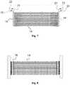
Figure 1 . - Figure 7
- shows a side view of the tube pack of
Figure 6 . - Figure 8
- shows a top view of the tube pack of
Figure 6 . - Figure 9
- shows a perspective view of the tube pack of
Figure 6 . - Figure 10
- shows a side view of the tube pack in greater detail.
- The heat exchanger according to the example of
Figure 1 is constructed in a parallelepiped-shaped box-like casing, which is referred to hereinafter as thebody 1. The body is assembled from rectangular cavity-profile sheet, from which the exchanger's bottom 2 ends 3, 4,side walls cover 7 are formed. Thebottom 2,side walls cover 7 are parallel and form the long sides of the body and their direction defines the longitudinal axis of the body. A cavity-profile sheet consists of cavities, in this case rectangular, separated by partitions, and two opposing surfaces. The shape of the cavities can naturally vary, what is important is that by means of the cavity structure a light, but relatively rigid sheet is obtained. Thus, the material's stiffness and strength are sufficient for manufacturing the body of the heat exchanger. Thebody 1 is assembled on top of the sheet forming thebottom 2, in such a way that the end andside walls bottom 2. Thus, the edges of thebottom 2 form an anchor when the heat exchanger is placed inside the ground. The ends 3, 4 andside walls bottom 2 and to each other at the corners. Theside walls vertical supports 8 running transversely to the walls, which are here rectangular in cross-section and set at right angles to the cavities of the walls. Here, the cavities of theside walls tube 9, which is in addition attached to the wall by anattachment plate 10, acts as a longitudinal stiffener and is fitted through thevertical supports 8 at more or less the centre of the wall. Thetube 9 can be used as an attachment point when moving the heat exchanger and also acts as vertical anchoring, for instance, against the possible buoyancy of groundwater when the heat exchanger is sunk into the ground. - A
cover 7 is formed on the opposite side of thebody 1 to thebottom 2. The cavities in the cover are transverse to the longitudinal direction of the body and stiffeners with a rectangular cross-section are fitted to the edges of thecover 7 on its long sides. In addition, there are maintenance/inspection openings 11 in the cover. One essential feature of the invention is precisely thecover 7 closing the upper part of the body. The opening closed by thecover 7 is now formed by a rectangle delimited by theside walls tube pack 12 of the heat exchanger must fit inside the space delimited by thewalls cover 7 must large enough and shaped in such a way that thetube pack 12, preferably with its attachments, will fit through it. Thecover 7 closes this opening. When the heat exchanger is assembled, the tube pack is lifted, ready assembled, through the opening and into the body, into which it can now be easily fitted. - The
cover 7 can be attached permanently in place after the assembling of the heat exchanger, for instance by welding, but preferably the cover is openable, so that thetube pack 12 can be more easily cleaned in place or lifted out of the box or container-like body 1 for maintenance or repair. Though there aremaintenance openings 11 in the tube heat exchanger, as in this example, thetube pack 12 fills the space inside the body and it is mainly only inspections, but not really maintenance operations that can be made through theopenings 11. Thus, it is preferable to attach thecover 7 to the rest of thebody 1 in such a way that the cover can be opened. To attach thecover 7, for example, bolted joints, hinge and lock structures, or, for instance, locking wedges can be used. The joint between thecover 7 and thebody 1 must naturally be sealed, either structurally or by using a seal. - The equipment of the
body 1 further includes, for instance, water inlet andoutlet connections 13, which are located at theends body 1, as well as some other accessories that do not particularly relate to the invention. - A
tube pack 12 consisting of heat-exchange pipework, which is formed of severalparallel tube rows 15 assembled fromseveral tubes 14 arranged on top of each other, is fitted inside thebody 1. The tubes of the tube pack are parallel to the longitudinal axis of thebody 1. Figure 10 shows a side view of one such tube pack. Each of thetubes 14 on top of each other is connected at its ends to the end of an upper or corresponding lower tube by a butt or electrically welded reversingpiece 16, in such a way that the other end of theupper tube 17 andlower tube 18 is open. In this way a long, meandering liquid channel is formed, in which the direction of travel of the liquid always changes at the ends of thetubes 14. The free open end of thelower tube 18 of eachtube row 15 is connected by aconnector tube 19 to thelower manifold 20 and the free open end of theupper tube 17 by aconnector tube 21 to theupper manifold 22. Thetube rows 15 are placed in parallel, in such a way that the open ends of the lower 18 and upper 17 tubes of onetube row 15 are on one side of thetube pack 12, then in the parallel tube rows all the ends are blocked by a reversingpiece 16 and the open ends on the opposite side. Thus, everysecond tube row 15 connects to themanifolds tube pack 12 and everyother tube row 15 parallel to them is, in turn, connected to themanifolds tubes 14 and removed after circulating through thetube row 15 through the second manifold. Each of themanifolds side wall body 1, thus forming inlet and outlet connections for the circulating liquid. The circulating liquid can be, for example, a generally used ethanol-based liquid.- Seven
rectangular baffle plates 23 are located along the length of thetube pack 12, which at the same time support and stiffen the tube pack and, for their part, also increase the strength of thebody 1. The baffle plates are intended to create mixing in the heat-transfer medium and thus to transfer heat as efficiently as possible between the heat-transfer medium flowing in thetubes 15 and the heat-transfer medium surrounding them. Thebaffle plates 23 also support the heat-transfer tube pack 12 on the inner surface of thebody 1. Ifrectangular baffle plates 23 covering half of the tube pack are used, the distance between them should be at least 1/5 of the inner dimension of the body, however at least 50 mm. The maximum distance should not exceed the internal dimension of thebody 1 and, when thebaffle plates 23 act as support plates for the heat-transfer tubes, their mechanical stresses, such as strength and vibrations must be taken into account. More detailed instructions for the design of the heat exchanger in this connection are available from the handbooks and dimensioning guides of the sector. - The heat exchanger is dimensioned according to the application. It is preferable to use polyolefins, such as polyethylene and polypropylene, as the material of the body and other parts of the heat exchanger, on account of their good ice-formation-preventing properties.
- The manufacturing material of the
tubes 14 of the tube pack is preferably a material, which has essentially the same thermal expansion coefficient and chemical resistance as the corresponding properties of the body and other parts of the heat exchanger. The said same polyolefin materials are one advantageous example. The shape of the cross-section of the tubes is preferably a circle, due to ease of manufacture, but it can also be a simple equal-walled rectangle, or an oval, or there can be longitudinal or transverse finning or other protrusions in its internal or external surfaces or in both, in order to increase the heat-transfer surface. The shape of the tube profile can be chosen as desired, but in terms of manufacturing technique the manufacture of a standard-shape profile in the longitudinal direction is easiest. If the heat-transfer liquid easily dirties, the surface of the tube profile is preferably smooth and the internal surface of the profile can be surfaced or mixed with a substance that decreases dirtying. The internal surface of the tube profile is also preferably smooth, in order to minimize pressure losses. It can, of course, be envisaged that the tube profile is manufactured from a composite material of two or more layers, if the operating conditions demand this. In composite tubes, the layers of the layer structure can consist of the same or different materials. One example is a plastic-metal composite tube, and other example reinforced plastic tubes, in which are generally an inner and outer layer of a resin-rich material, and between them a reinforced layer to reinforce the strong structure. - Plastic materials generally have a good chemical resistance, so that with their aid the heat exchanger can be designed to operate in chemically demanding applications, in which, for example, salt content and pH set limits to the choice of materials.
- The number of
tubes 14 of the heat-transfer tube pack 12 and their placing inside thebody 1 can vary. However, in order that the heat-transfer capacity of the heat exchanger will be sufficient, thetube rows 15 should be several, at least more than 5 and preferably more than 10 rows. The number of course varies according to the size of the heat exchanger. The basic rule is that the distance between the outer walls of the heat-transfer tubes should be at least 0.25 times the tube diameter. - The liquid of the secondary circuit of the invention is preferably water, which can be seawater, freshwater, sewage, or industrial process water. The liquid of the primary circuit can also be water, especially when the heat exchanger is used as a cooler. If the heat exchanger is used with a heat pump or some other device that circulates a refrigerant, then of course a refrigerant suitable for the purpose must be used. The refrigerant will then determine its suitability for the device being used.
- Within the scope of the invention, it is also possible to envisage solutions differing from the embodiments described above. For example, it can be envisaged that the cross-section of the
body 1 is rectangular, cylindrical, polygonal, or some other cross-section. A straight parallelogram is, however, often the cheapest to manufacture and will sufficiently withstand an external load. - The main components of the heat exchanger are preferably made from polyolefin plastics, but naturally other materials can be used as required, for example seals, screws, bolts, hinge pins, and similar made from steel, without deviating from the basic idea of the invention.
- One advantageous implementation alternative for the body is the aforementioned cavity-profile sheet. If only weldable plastic is used as the manufacturing material, the heat exchanger can advantageously be manufactured by welding. If different materials are used and welding is not possible, other construction alternatives can be used, such as flange joints.
- Instead of cavity-profile sheet, on at least one side compact profile sheets can be used. In one embodiment, the entire body 1 (i.e. casing) of the heat exchanger is manufactured from such profile sheets. Their wall thickness is generally about 10 - 200 mm, especially about 20 - 100 mm.
- The plastic materials can be mixed with soot, graphite, talc, lithium, magnetite, barium sulphate, and metallic-derivative additives.
- Heat exchangers according to the present technology are manufactured mainly for use on an industrial scale. Thus, the length of a single heat exchanger is generally about 500 - 10 000 mm, especially about 1000 - 7500 mm, most suitably about 1000 - 5000 mm; with a width of about 100 - 5000 mm, especially about 250 - 3000 mm, and a height of about 100 - 5000 mm, especially about 500 - 3000 mm.
- The diameter of the heat-transfer tubes of heat exchangers is usually about 10 - 500 mm, especially about 25 - 300 mm, most suitably about 30 - 200 mm. There are generally 10 - 200 heat-transfer tubes to a heat exchanger, especially 10 - 100 to a heat exchanger.
- 1
- body
- 2
- bottom
- 3, 4
- end walls
- 5, 6
- side walls
- 7
- cover
- 8
- vertical supports
- 9
- tube
- 10
- attachment plate
- 11
- maintenance/inspection openings
- 12
- tube pack
- 13
- water inlet and outlet connections
- 14
- tubes
- 15
- parallel tube rows
- 16
- reversing pieces
- 17
- upper tube
- 18
- lower tube
- 19,21
- connector tube
- 20, 22
- manifold
- 23
- baffle plates
WO 201167457 CN2715090 US 3 426841DE 10 2010 000421
Claims (15)
- Heat exchanger for low temperatures, which heat exchanger comprises:- a body (1) manufactured from planar profile sheet,forming the exchanger's bottom (2), ends (3, 4), side walls (5, 6) and a cover (7),characterized in that the the body is assembled from rectangular cavity-profile sheet consisting of cavities separated by partitions and two opposing surfaces.,- a tube pack (12) fitted inside the body (1) for circulating a first heat-exchange medium in the heat exchanger, connections (20, 22) to lead the heat-transfer medium to the tube pack (12) and from the tube pack,- an opening arranged in at least one long side (7) of the body (1), which is dimensioned to be large enough that the tube pack (12) forming at least one circuit of the heat exchanger can be fitted inside the body (1) through the opening,- a cover (7) arranged to close the opening, and- a further connection (13) for leading the heat-transfer medium inside the body,wherein- at least the body is manufactured from plastic material, and- the heat exchanger comprises a further connection (13) for leading the heat-transfer medium from the body,
- Heat exchanger according to Claim 1,characterized in that the tube pack is formed of tube profiles, which are made from plastic material.
- Heat exchanger according to Claim 1 or 2,characterized in that the body (1) and tube profiles are made from polyolefins, such as polyethylene or polypropylene or a combination of these.
- Heat exchanger according to Claim 1 or 2,characterized in that the cover (7) is openable.
- Heat exchanger according to any of the above Claims,characterized in that the body (1) of the heat exchanger is made from planar cavity-profile sheet.
- Heat exchanger according to Claim 5,characterized in that the cavities of the cavity-profile sheet are filled at least partly with a filler, for example, a thermally insulating substance or a substance that is heavier than water.
- Heat exchanger according to any of the above Claims,characterized in that there are protrusions on the surface of the profiles of the tubes (14) of at least one tube pack (12).
- Heat exchanger according to any of the above Claims,characterized the inner surface of the tubes (14) of the tube pack (12) is smooth.
- Heat exchanger according to any of the above Claims,characterized in that at least the inner surface of the tubes (14) of the tube pack (12) is surfaced or mixed with a substance that prevents dirtying.
- Heat exchanger according to any of the above Claims,characterized by a longitudinal stiffener (9) fitted to at least one long side of the body (1).
- Heat exchanger according to any of the above Claims,characterized in that at least one tube pack (12) of the heat exchanger comprises parallel tube rows (15) consisting of at least two elongated tubes (14) arranged on top of each other, in which the tubes (14, 17, 18) on top of each other are connected alternately at their ends in order to form a liquid channel.
- Heat exchanger according to Claim 11,characterized in that the parallel tube rows (15) are connected to two manifolds (20, 22), through which the liquid circulation of the tube rows (15) is arranged.
- Heat exchanger according to Claim 11 or 12,characterized in that manifolds (20, 22) are situated at both ends of the tube pack (15) and the parallel tube rows (15) are connected alternately to the manifolds (20, 22) at different ends.
- Heat exchanger according to any of the above Claims,characterized in that the body (1) comprises a bottom plate (2), which is wider in at least one direction than the casing formed on top of the bottom plate (2) of the body (1).
- Heat exchanger according to any of the above Claims,characterized in that the heat exchanger is manufactured from a weldable polymer material.
Applications Claiming Priority (2)
| Application Number | Priority Date | Filing Date | Title |
|---|---|---|---|
| FI20145206AFI126014B (en) | 2014-03-04 | 2014-03-04 | Low temperature heat exchanger |
| PCT/FI2015/050136WO2015132468A1 (en) | 2014-03-04 | 2015-03-04 | Heat exchanger for low temperatures |
Publications (2)
| Publication Number | Publication Date |
|---|---|
| EP3117170A1 EP3117170A1 (en) | 2017-01-18 |
| EP3117170B1true EP3117170B1 (en) | 2020-04-29 |
Family
ID=52991752
Family Applications (1)
| Application Number | Title | Priority Date | Filing Date |
|---|---|---|---|
| EP15717524.1ANot-in-forceEP3117170B1 (en) | 2014-03-04 | 2015-03-04 | Heat exchanger for low temperatures |
Country Status (7)
| Country | Link |
|---|---|
| US (1) | US20170067692A1 (en) |
| EP (1) | EP3117170B1 (en) |
| CN (1) | CN105308407A (en) |
| CA (1) | CA2941094A1 (en) |
| EA (1) | EA031914B1 (en) |
| FI (1) | FI126014B (en) |
| WO (1) | WO2015132468A1 (en) |
Families Citing this family (5)
| Publication number | Priority date | Publication date | Assignee | Title |
|---|---|---|---|---|
| ES2652517B1 (en)* | 2015-04-30 | 2019-01-22 | Madrid Fly S L | EXCHANGER FOR WIND TUNNEL |
| RU172248U1 (en)* | 2016-04-04 | 2017-07-03 | Дмитрий Леонидович Грохольский | Shell-and-tube heat exchanger with a composite tube sheet |
| RU203048U1 (en)* | 2020-09-07 | 2021-03-19 | Семен Александрович Араканцев | UNIVERSAL FLOW HEAT EXCHANGER |
| CN112747500A (en)* | 2021-01-21 | 2021-05-04 | 青岛海信建筑设计院有限公司 | Sewage source heat pump in building plumbing |
| FI20225776A1 (en) | 2022-09-05 | 2024-03-06 | Uponor Infra Oy | Heat exchanger and method for its production |
Family Cites Families (78)
| Publication number | Priority date | Publication date | Assignee | Title |
|---|---|---|---|---|
| US1875142A (en)* | 1930-11-26 | 1932-08-30 | Griscomrussell Company | Heat exchanger |
| US1935066A (en)* | 1931-12-31 | 1933-11-14 | Superheater Co Ltd | Heat exchanger |
| US1962362A (en)* | 1933-02-28 | 1934-06-12 | Lummus Co | Two pass heat exchanger |
| US2311190A (en)* | 1942-03-19 | 1943-02-16 | American Locomotive Co | Heat exchanger |
| US2514797A (en)* | 1946-01-24 | 1950-07-11 | Raytheon Mfg Co | Heat exchanger |
| US2615687A (en)* | 1948-01-03 | 1952-10-28 | American Blower Corp | Heat exchanger |
| US2656157A (en)* | 1950-02-16 | 1953-10-20 | Eugene W Wasielewski | Heat transfer element supported against external or internal pressures |
| US2938712A (en)* | 1955-05-03 | 1960-05-31 | Svenska Flaektfabriken Ab | Air preheater |
| US2877000A (en)* | 1955-09-16 | 1959-03-10 | Int Harvester Co | Heat exchanger |
| US3153446A (en)* | 1960-08-12 | 1964-10-20 | United Aircraft Corp | Heat exchanger |
| NL273035A (en)* | 1960-12-29 | |||
| US3183969A (en)* | 1962-02-28 | 1965-05-18 | Foster Wheeler Corp | Heat exchangers |
| FR1351602A (en)* | 1962-12-29 | 1964-02-07 | Babcock & Wilcox France | Improvements to recovery heat exchangers |
| FR1238173A (en)* | 1965-02-06 | 1960-08-05 | Ford | Carburetor heater |
| US3426841A (en) | 1966-05-18 | 1969-02-11 | Herbert G Johnson | Heat exchangers having plastic components |
| US3804160A (en)* | 1970-05-26 | 1974-04-16 | Du Pont | Fluid heat exchange system |
| US3863712A (en)* | 1970-08-14 | 1975-02-04 | Frank T Smith | Liquid heat exchange system |
| US3805881A (en)* | 1971-08-17 | 1974-04-23 | Du Pont | Fluid heat exchange system |
| US4054980A (en)* | 1972-04-20 | 1977-10-25 | Square S.A. | Process for manufacturing modular elements and a tube nest for heat exchangers |
| US4138969A (en)* | 1977-07-08 | 1979-02-13 | Applied Engineering Co. | Heat exchanger and economizer |
| US4342359A (en)* | 1977-12-12 | 1982-08-03 | Baker Jack T | Universal flue stack heat exchanger |
| US4354546A (en)* | 1980-07-17 | 1982-10-19 | Bio-Energy Systems, Inc. | Header pair and double tube mat connection |
| US4872504A (en)* | 1982-09-13 | 1989-10-10 | Plascore, Inc. | Modular heat exchanger housing |
| JPS60159596A (en)* | 1984-01-30 | 1985-08-21 | Agency Of Ind Science & Technol | Prevention of stain by living organism |
| US4693302A (en)* | 1984-12-28 | 1987-09-15 | Leonard Oboler | Heat exchanging apparatus for cooling and condensing by evaporation |
| US4596285A (en)* | 1985-03-28 | 1986-06-24 | North Atlantic Technologies, Inc. | Heat exchanger with resilient corner seals |
| US4899814A (en)* | 1986-12-31 | 1990-02-13 | Price Richard C | High pressure gas/liquid heat exchanger |
| MY110237A (en)* | 1987-05-25 | 1998-03-31 | Dunham Bush International Cayman Ltd | Improved method of manufacturing heat exchangers |
| JPH01157960U (en)* | 1988-04-25 | 1989-10-31 | ||
| US4966230A (en)* | 1989-01-13 | 1990-10-30 | Modine Manufacturing Co. | Serpentine fin, round tube heat exchanger |
| US5001906A (en)* | 1989-05-04 | 1991-03-26 | Chicago Bridge & Iron Technical Services Company | High pressure heat exchanger for cooling high fouling liquids |
| CA2030577C (en)* | 1990-11-23 | 1994-10-11 | Mircea Dinulescu | Plate type heat exchanger |
| US5248454A (en)* | 1992-04-10 | 1993-09-28 | Munters Corporation | Algae resistant edge coating |
| US5944089A (en)* | 1994-05-26 | 1999-08-31 | Roland; Russel Anthony | Thermal storage systems for buildings |
| US5579650A (en)* | 1994-12-05 | 1996-12-03 | Cleland; Robert K. | Heat exchanger |
| US5725047A (en)* | 1995-01-13 | 1998-03-10 | Lytron Incorporated | Heat exchanger |
| JP3059393B2 (en)* | 1996-11-26 | 2000-07-04 | 日本ピラー工業株式会社 | Heat exchanger |
| US5875837A (en)* | 1998-01-15 | 1999-03-02 | Modine Manufacturing Company | Liquid cooled two phase heat exchanger |
| US6113782A (en)* | 1998-07-28 | 2000-09-05 | Terumo Cardiovascular Systems Corporation | Potting of tubular bundles in housing |
| JP3946459B2 (en)* | 2001-05-02 | 2007-07-18 | リンナイ株式会社 | Water heater liquid-liquid heat exchanger |
| DE10219127A1 (en)* | 2002-04-29 | 2003-11-06 | Inst Neue Mat Gemein Gmbh | Substrates with a biofilm-inhibiting coating |
| US20040069470A1 (en)* | 2002-09-10 | 2004-04-15 | Jacob Gorbulsky | Bent-tube heat exchanger |
| KR100502514B1 (en)* | 2003-03-04 | 2005-07-25 | 정아라 | Heat exchanger for wasted heat |
| US6988532B2 (en)* | 2003-10-27 | 2006-01-24 | Denso Corporation | Heat exchanger |
| US20070251091A1 (en)* | 2003-12-24 | 2007-11-01 | Showa Denko K.K. | Heat Exchanger And Method For Manufacturing The Same |
| US6820685B1 (en)* | 2004-02-26 | 2004-11-23 | Baltimore Aircoil Company, Inc. | Densified heat transfer tube bundle |
| GB2413842B (en)* | 2004-05-07 | 2006-06-21 | Matthew Rutherford | Heat-exchange units |
| US6899169B1 (en)* | 2004-07-02 | 2005-05-31 | Richard D. Cox | Plastic heat exchanger |
| CN2715090Y (en) | 2004-07-20 | 2005-08-03 | 成都希望电子研究所 | A heat exchange structure for tube bundle type heat exchanger |
| US7406957B2 (en)* | 2006-02-17 | 2008-08-05 | Phillips & Temro Industries Inc. | Air heater with one-piece housing |
| US20080016901A1 (en)* | 2006-07-24 | 2008-01-24 | Leary Wilson M | Heat exchanger |
| DE102006050922A1 (en)* | 2006-10-28 | 2008-04-30 | Hans Huber Ag Maschinen- Und Anlagenbau | Transmitting heat between wastewater e.g. domestic wastewater located in sand trap and fluid e.g. oil by heat exchanger, comprises producing convective flow that moves the wastewater along outer surface of the exchanger, in the wastewater |
| PL1985909T3 (en)* | 2007-04-25 | 2011-08-31 | Oy Kwh Pipe Ab | Method and apparatus for coating pipes |
| DE102008002746A1 (en)* | 2007-07-11 | 2009-02-12 | Visteon Global Technologies Inc., Van Buren | Heat exchanger for the exhaust system of a motor vehicle, method for producing a heat exchanger and assembly tool for this purpose |
| EP2015017A1 (en)* | 2007-07-12 | 2009-01-14 | Hexion Specialty Chemicals Research Belgium S.A. | Heat exchanger |
| AU2009205434B2 (en)* | 2008-01-14 | 2013-06-20 | The Babcock & Wilcox Company | Heat exchanger |
| EP2298455A1 (en)* | 2009-09-17 | 2011-03-23 | Borealis AG | Method of coating pipes or pipe sections |
| DE102009055715A1 (en)* | 2009-11-26 | 2011-06-01 | Behr Gmbh & Co. Kg | Intake manifold with integrated intercooler |
| FI20096291A0 (en)* | 2009-12-04 | 2009-12-04 | Mateve Oy | Earth circuit in a low energy system |
| DE102010000421B4 (en) | 2010-02-15 | 2012-08-09 | Polytetra Gmbh | Tube bundle heat exchanger |
| CN102235828A (en)* | 2010-04-27 | 2011-11-09 | 张爱新 | Teflon cold and heat exchanger |
| IT1400944B1 (en)* | 2010-07-01 | 2013-07-02 | Cipriani | CONFINEMENT GROUP OF A PLATE HEAT EXCHANGER, METHOD FOR ITS ACHIEVEMENT AS A METHOD OF ABSORPTION OF EFFORTS IN A CONFINEMENT GROUP FOR PLATFORM HEAT EXCHANGERS. |
| CN201772812U (en)* | 2010-07-26 | 2011-03-23 | 济南西斯普换热系统有限公司 | Corrosion-resistant plastic heat exchanger |
| US9127897B2 (en)* | 2010-12-30 | 2015-09-08 | Kellogg Brown & Root Llc | Submersed heat exchanger |
| US20120168137A1 (en)* | 2011-01-03 | 2012-07-05 | Osvaldo Del Campo | Compressed natural gas (cng) sub-cooling system for cng-filling stations |
| FR2977307B1 (en)* | 2011-06-30 | 2013-08-09 | Valeo Systemes Thermiques | STACKED PLATE EXCHANGER HOUSING AND EXCHANGER COMPRISING SUCH A HOUSING |
| FR2980837B1 (en)* | 2011-10-04 | 2015-06-26 | Valeo Systemes Thermiques | HEAT EXCHANGER WITH STACKED PLATES. |
| FI126176B (en)* | 2011-10-17 | 2016-07-29 | Uponor Infra Oy | A method for manufacturing a sheet structure |
| DK2597412T3 (en)* | 2011-11-28 | 2014-08-11 | Alfa Laval Corp Ab | BLOCK-TYPE PLATE HEAT EXCHANGERS WITH ANTI-FAVORING PROPERTIES |
| FI124230B (en)* | 2012-05-28 | 2014-05-15 | Vahterus Oy | PROCEDURES AND ARRANGEMENTS FOR REPAIRING A HEAT EXCHANGE PLATE PACKAGE AND PLATE HEAT EXCHANGER |
| DE102012211857A1 (en)* | 2012-07-06 | 2014-01-09 | Behr Gmbh & Co. Kg | Heat exchanger |
| DE102012106782A1 (en)* | 2012-07-26 | 2014-01-30 | Halla Visteon Climate Control Corporation | Heat exchanger for exhaust gas cooling in motor vehicles |
| CN202793099U (en)* | 2012-09-24 | 2013-03-13 | 珠海格力电器股份有限公司 | heat exchanger and water source heat pump multi-connected unit |
| CN202895794U (en)* | 2012-12-03 | 2013-04-24 | 温州天瑞新材料科技有限公司 | Hollow plastic plate |
| CN103115506A (en)* | 2013-02-26 | 2013-05-22 | 广东保迪环保电镀设备有限公司 | Electroless Nickel Plating Solution Cooler |
| EP2981782A1 (en)* | 2013-04-04 | 2016-02-10 | Brentwood Industries, Inc. | Polymeric coil assembly and method of making the same |
| CN103557722B (en)* | 2013-10-28 | 2015-04-15 | 杭州沈氏节能科技股份有限公司 | Heat exchanger with double-shell structure |
| KR102538941B1 (en)* | 2014-12-12 | 2023-06-01 | 코닌클리케 필립스 엔.브이. | Cooling apparatus for cooling a fluid by means of surface water |
- 2014
- 2014-03-04FIFI20145206Apatent/FI126014B/enactiveIP Right Grant
- 2015
- 2015-03-04CNCN201580000777.0Apatent/CN105308407A/enactivePending
- 2015-03-04WOPCT/FI2015/050136patent/WO2015132468A1/enactiveApplication Filing
- 2015-03-04CACA2941094Apatent/CA2941094A1/ennot_activeAbandoned
- 2015-03-04USUS15/122,639patent/US20170067692A1/ennot_activeAbandoned
- 2015-03-04EAEA201691545Apatent/EA031914B1/ennot_activeIP Right Cessation
- 2015-03-04EPEP15717524.1Apatent/EP3117170B1/ennot_activeNot-in-force
Non-Patent Citations (1)
| Title |
|---|
| None* |
Also Published As
| Publication number | Publication date |
|---|---|
| CN105308407A (en) | 2016-02-03 |
| EP3117170A1 (en) | 2017-01-18 |
| EA201691545A1 (en) | 2017-02-28 |
| US20170067692A1 (en) | 2017-03-09 |
| EA031914B1 (en) | 2019-03-29 |
| WO2015132468A1 (en) | 2015-09-11 |
| FI20145206A7 (en) | 2015-09-05 |
| FI126014B (en) | 2016-05-31 |
| CA2941094A1 (en) | 2015-09-11 |
Similar Documents
| Publication | Publication Date | Title |
|---|---|---|
| EP3117170B1 (en) | Heat exchanger for low temperatures | |
| CN103649666A (en) | Thermal energy storage and plant, method and use thereof | |
| KR20000035105A (en) | Heat exchange members for thermal storage apparatus | |
| EP2844941B1 (en) | Heat exchanger | |
| CN101929811A (en) | A shell-and-tube heat exchanger with multi-shell-side countercurrent speed-up | |
| CN102353185A (en) | Micro-channel condenser for heat pump water heater | |
| CN104412059A (en) | Heat exchanger | |
| CN203731913U (en) | Energy storage heat exchanger | |
| CN104990438B (en) | A kind of phase-change type heat-storing device with inner water-tank | |
| US20140216701A1 (en) | Heat exchanger and heat management system having such a heat exchanger | |
| CN201811611U (en) | A shell-and-tube heat exchanger with multi-shell-side countercurrent speed-up | |
| CN210602930U (en) | Heat pipe and heat exchanger | |
| JP2009014260A (en) | Underground heat collection tank | |
| CN204461156U (en) | Waste water heat reclaim unit | |
| CN209623188U (en) | A kind of cold storage refrigerating system water storage pool | |
| CN208296647U (en) | A kind of petroleum pipeline heat-exchanger rig | |
| JP4921952B2 (en) | Thermal storage tank and thermal storage air conditioning system | |
| CN205279822U (en) | High temperature heat pipe exchanger is taken a fancy to to gas -liquid | |
| CN203824375U (en) | Inner fin plate heat exchanger | |
| CN218955167U (en) | Energy storage device and air conditioning system | |
| CN219015047U (en) | Efficient heat exchanger | |
| KR102584145B1 (en) | a structure which preventing freezing with contraction tube | |
| RU150772U1 (en) | COLD BATTERY | |
| CN212408950U (en) | Cold radiation air conditioner | |
| CN201837009U (en) | Nano heat-conducting composite ice storage device with coil pipes |
Legal Events
| Date | Code | Title | Description |
|---|---|---|---|
| STAA | Information on the status of an ep patent application or granted ep patent | Free format text:STATUS: THE INTERNATIONAL PUBLICATION HAS BEEN MADE | |
| PUAI | Public reference made under article 153(3) epc to a published international application that has entered the european phase | Free format text:ORIGINAL CODE: 0009012 | |
| STAA | Information on the status of an ep patent application or granted ep patent | Free format text:STATUS: REQUEST FOR EXAMINATION WAS MADE | |
| 17P | Request for examination filed | Effective date:20160922 | |
| AK | Designated contracting states | Kind code of ref document:A1 Designated state(s):AL AT BE BG CH CY CZ DE DK EE ES FI FR GB GR HR HU IE IS IT LI LT LU LV MC MK MT NL NO PL PT RO RS SE SI SK SM TR | |
| AX | Request for extension of the european patent | Extension state:BA ME | |
| DAV | Request for validation of the european patent (deleted) | ||
| DAX | Request for extension of the european patent (deleted) | ||
| GRAP | Despatch of communication of intention to grant a patent | Free format text:ORIGINAL CODE: EPIDOSNIGR1 | |
| STAA | Information on the status of an ep patent application or granted ep patent | Free format text:STATUS: GRANT OF PATENT IS INTENDED | |
| INTG | Intention to grant announced | Effective date:20190920 | |
| GRAS | Grant fee paid | Free format text:ORIGINAL CODE: EPIDOSNIGR3 | |
| GRAA | (expected) grant | Free format text:ORIGINAL CODE: 0009210 | |
| STAA | Information on the status of an ep patent application or granted ep patent | Free format text:STATUS: THE PATENT HAS BEEN GRANTED | |
| AK | Designated contracting states | Kind code of ref document:B1 Designated state(s):AL AT BE BG CH CY CZ DE DK EE ES FI FR GB GR HR HU IE IS IT LI LT LU LV MC MK MT NL NO PL PT RO RS SE SI SK SM TR | |
| REG | Reference to a national code | Ref country code:GB Ref legal event code:FG4D | |
| REG | Reference to a national code | Ref country code:CH Ref legal event code:EP | |
| REG | Reference to a national code | Ref country code:DE Ref legal event code:R096 Ref document number:602015051606 Country of ref document:DE | |
| REG | Reference to a national code | Ref country code:AT Ref legal event code:REF Ref document number:1263946 Country of ref document:AT Kind code of ref document:T Effective date:20200515 | |
| REG | Reference to a national code | Ref country code:IE Ref legal event code:FG4D | |
| REG | Reference to a national code | Ref country code:NL Ref legal event code:MP Effective date:20200429 | |
| REG | Reference to a national code | Ref country code:LT Ref legal event code:MG4D | |
| PG25 | Lapsed in a contracting state [announced via postgrant information from national office to epo] | Ref country code:IS Free format text:LAPSE BECAUSE OF FAILURE TO SUBMIT A TRANSLATION OF THE DESCRIPTION OR TO PAY THE FEE WITHIN THE PRESCRIBED TIME-LIMIT Effective date:20200829 Ref country code:FI Free format text:LAPSE BECAUSE OF FAILURE TO SUBMIT A TRANSLATION OF THE DESCRIPTION OR TO PAY THE FEE WITHIN THE PRESCRIBED TIME-LIMIT Effective date:20200429 Ref country code:NO Free format text:LAPSE BECAUSE OF FAILURE TO SUBMIT A TRANSLATION OF THE DESCRIPTION OR TO PAY THE FEE WITHIN THE PRESCRIBED TIME-LIMIT Effective date:20200729 Ref country code:PT Free format text:LAPSE BECAUSE OF FAILURE TO SUBMIT A TRANSLATION OF THE DESCRIPTION OR TO PAY THE FEE WITHIN THE PRESCRIBED TIME-LIMIT Effective date:20200831 Ref country code:SE Free format text:LAPSE BECAUSE OF FAILURE TO SUBMIT A TRANSLATION OF THE DESCRIPTION OR TO PAY THE FEE WITHIN THE PRESCRIBED TIME-LIMIT Effective date:20200429 Ref country code:LT Free format text:LAPSE BECAUSE OF FAILURE TO SUBMIT A TRANSLATION OF THE DESCRIPTION OR TO PAY THE FEE WITHIN THE PRESCRIBED TIME-LIMIT Effective date:20200429 Ref country code:GR Free format text:LAPSE BECAUSE OF FAILURE TO SUBMIT A TRANSLATION OF THE DESCRIPTION OR TO PAY THE FEE WITHIN THE PRESCRIBED TIME-LIMIT Effective date:20200730 | |
| REG | Reference to a national code | Ref country code:AT Ref legal event code:MK05 Ref document number:1263946 Country of ref document:AT Kind code of ref document:T Effective date:20200429 | |
| PG25 | Lapsed in a contracting state [announced via postgrant information from national office to epo] | Ref country code:BG Free format text:LAPSE BECAUSE OF FAILURE TO SUBMIT A TRANSLATION OF THE DESCRIPTION OR TO PAY THE FEE WITHIN THE PRESCRIBED TIME-LIMIT Effective date:20200729 Ref country code:HR Free format text:LAPSE BECAUSE OF FAILURE TO SUBMIT A TRANSLATION OF THE DESCRIPTION OR TO PAY THE FEE WITHIN THE PRESCRIBED TIME-LIMIT Effective date:20200429 Ref country code:LV Free format text:LAPSE BECAUSE OF FAILURE TO SUBMIT A TRANSLATION OF THE DESCRIPTION OR TO PAY THE FEE WITHIN THE PRESCRIBED TIME-LIMIT Effective date:20200429 Ref country code:RS Free format text:LAPSE BECAUSE OF FAILURE TO SUBMIT A TRANSLATION OF THE DESCRIPTION OR TO PAY THE FEE WITHIN THE PRESCRIBED TIME-LIMIT Effective date:20200429 | |
| PG25 | Lapsed in a contracting state [announced via postgrant information from national office to epo] | Ref country code:AL Free format text:LAPSE BECAUSE OF FAILURE TO SUBMIT A TRANSLATION OF THE DESCRIPTION OR TO PAY THE FEE WITHIN THE PRESCRIBED TIME-LIMIT Effective date:20200429 Ref country code:NL Free format text:LAPSE BECAUSE OF FAILURE TO SUBMIT A TRANSLATION OF THE DESCRIPTION OR TO PAY THE FEE WITHIN THE PRESCRIBED TIME-LIMIT Effective date:20200429 | |
| PG25 | Lapsed in a contracting state [announced via postgrant information from national office to epo] | Ref country code:EE Free format text:LAPSE BECAUSE OF FAILURE TO SUBMIT A TRANSLATION OF THE DESCRIPTION OR TO PAY THE FEE WITHIN THE PRESCRIBED TIME-LIMIT Effective date:20200429 Ref country code:AT Free format text:LAPSE BECAUSE OF FAILURE TO SUBMIT A TRANSLATION OF THE DESCRIPTION OR TO PAY THE FEE WITHIN THE PRESCRIBED TIME-LIMIT Effective date:20200429 Ref country code:DK Free format text:LAPSE BECAUSE OF FAILURE TO SUBMIT A TRANSLATION OF THE DESCRIPTION OR TO PAY THE FEE WITHIN THE PRESCRIBED TIME-LIMIT Effective date:20200429 Ref country code:CZ Free format text:LAPSE BECAUSE OF FAILURE TO SUBMIT A TRANSLATION OF THE DESCRIPTION OR TO PAY THE FEE WITHIN THE PRESCRIBED TIME-LIMIT Effective date:20200429 Ref country code:IT Free format text:LAPSE BECAUSE OF FAILURE TO SUBMIT A TRANSLATION OF THE DESCRIPTION OR TO PAY THE FEE WITHIN THE PRESCRIBED TIME-LIMIT Effective date:20200429 Ref country code:ES Free format text:LAPSE BECAUSE OF FAILURE TO SUBMIT A TRANSLATION OF THE DESCRIPTION OR TO PAY THE FEE WITHIN THE PRESCRIBED TIME-LIMIT Effective date:20200429 Ref country code:SM Free format text:LAPSE BECAUSE OF FAILURE TO SUBMIT A TRANSLATION OF THE DESCRIPTION OR TO PAY THE FEE WITHIN THE PRESCRIBED TIME-LIMIT Effective date:20200429 Ref country code:RO Free format text:LAPSE BECAUSE OF FAILURE TO SUBMIT A TRANSLATION OF THE DESCRIPTION OR TO PAY THE FEE WITHIN THE PRESCRIBED TIME-LIMIT Effective date:20200429 | |
| REG | Reference to a national code | Ref country code:DE Ref legal event code:R097 Ref document number:602015051606 Country of ref document:DE | |
| PG25 | Lapsed in a contracting state [announced via postgrant information from national office to epo] | Ref country code:PL Free format text:LAPSE BECAUSE OF FAILURE TO SUBMIT A TRANSLATION OF THE DESCRIPTION OR TO PAY THE FEE WITHIN THE PRESCRIBED TIME-LIMIT Effective date:20200429 Ref country code:SK Free format text:LAPSE BECAUSE OF FAILURE TO SUBMIT A TRANSLATION OF THE DESCRIPTION OR TO PAY THE FEE WITHIN THE PRESCRIBED TIME-LIMIT Effective date:20200429 | |
| PLBE | No opposition filed within time limit | Free format text:ORIGINAL CODE: 0009261 | |
| STAA | Information on the status of an ep patent application or granted ep patent | Free format text:STATUS: NO OPPOSITION FILED WITHIN TIME LIMIT | |
| 26N | No opposition filed | Effective date:20210201 | |
| PG25 | Lapsed in a contracting state [announced via postgrant information from national office to epo] | Ref country code:SI Free format text:LAPSE BECAUSE OF FAILURE TO SUBMIT A TRANSLATION OF THE DESCRIPTION OR TO PAY THE FEE WITHIN THE PRESCRIBED TIME-LIMIT Effective date:20200429 | |
| REG | Reference to a national code | Ref country code:DE Ref legal event code:R119 Ref document number:602015051606 Country of ref document:DE | |
| PG25 | Lapsed in a contracting state [announced via postgrant information from national office to epo] | Ref country code:MC Free format text:LAPSE BECAUSE OF FAILURE TO SUBMIT A TRANSLATION OF THE DESCRIPTION OR TO PAY THE FEE WITHIN THE PRESCRIBED TIME-LIMIT Effective date:20200429 | |
| REG | Reference to a national code | Ref country code:CH Ref legal event code:PL | |
| GBPC | Gb: european patent ceased through non-payment of renewal fee | Effective date:20210304 | |
| REG | Reference to a national code | Ref country code:BE Ref legal event code:MM Effective date:20210331 | |
| PG25 | Lapsed in a contracting state [announced via postgrant information from national office to epo] | Ref country code:DE Free format text:LAPSE BECAUSE OF NON-PAYMENT OF DUE FEES Effective date:20211001 Ref country code:IE Free format text:LAPSE BECAUSE OF NON-PAYMENT OF DUE FEES Effective date:20210304 Ref country code:GB Free format text:LAPSE BECAUSE OF NON-PAYMENT OF DUE FEES Effective date:20210304 Ref country code:FR Free format text:LAPSE BECAUSE OF NON-PAYMENT OF DUE FEES Effective date:20210331 Ref country code:LI Free format text:LAPSE BECAUSE OF NON-PAYMENT OF DUE FEES Effective date:20210331 Ref country code:LU Free format text:LAPSE BECAUSE OF NON-PAYMENT OF DUE FEES Effective date:20210304 Ref country code:CH Free format text:LAPSE BECAUSE OF NON-PAYMENT OF DUE FEES Effective date:20210331 | |
| PG25 | Lapsed in a contracting state [announced via postgrant information from national office to epo] | Ref country code:BE Free format text:LAPSE BECAUSE OF NON-PAYMENT OF DUE FEES Effective date:20210331 | |
| PG25 | Lapsed in a contracting state [announced via postgrant information from national office to epo] | Ref country code:HU Free format text:LAPSE BECAUSE OF FAILURE TO SUBMIT A TRANSLATION OF THE DESCRIPTION OR TO PAY THE FEE WITHIN THE PRESCRIBED TIME-LIMIT; INVALID AB INITIO Effective date:20150304 | |
| PG25 | Lapsed in a contracting state [announced via postgrant information from national office to epo] | Ref country code:CY Free format text:LAPSE BECAUSE OF FAILURE TO SUBMIT A TRANSLATION OF THE DESCRIPTION OR TO PAY THE FEE WITHIN THE PRESCRIBED TIME-LIMIT Effective date:20200429 | |
| PG25 | Lapsed in a contracting state [announced via postgrant information from national office to epo] | Ref country code:MK Free format text:LAPSE BECAUSE OF FAILURE TO SUBMIT A TRANSLATION OF THE DESCRIPTION OR TO PAY THE FEE WITHIN THE PRESCRIBED TIME-LIMIT Effective date:20200429 | |
| PG25 | Lapsed in a contracting state [announced via postgrant information from national office to epo] | Ref country code:TR Free format text:LAPSE BECAUSE OF FAILURE TO SUBMIT A TRANSLATION OF THE DESCRIPTION OR TO PAY THE FEE WITHIN THE PRESCRIBED TIME-LIMIT Effective date:20200429 | |
| PG25 | Lapsed in a contracting state [announced via postgrant information from national office to epo] | Ref country code:MT Free format text:LAPSE BECAUSE OF FAILURE TO SUBMIT A TRANSLATION OF THE DESCRIPTION OR TO PAY THE FEE WITHIN THE PRESCRIBED TIME-LIMIT Effective date:20200429 |